


cdrusn89
-
Posts
1,573 -
Joined
-
Last visited
Content Type
Profiles
Forums
Gallery
Events
Posts posted by cdrusn89
-
-
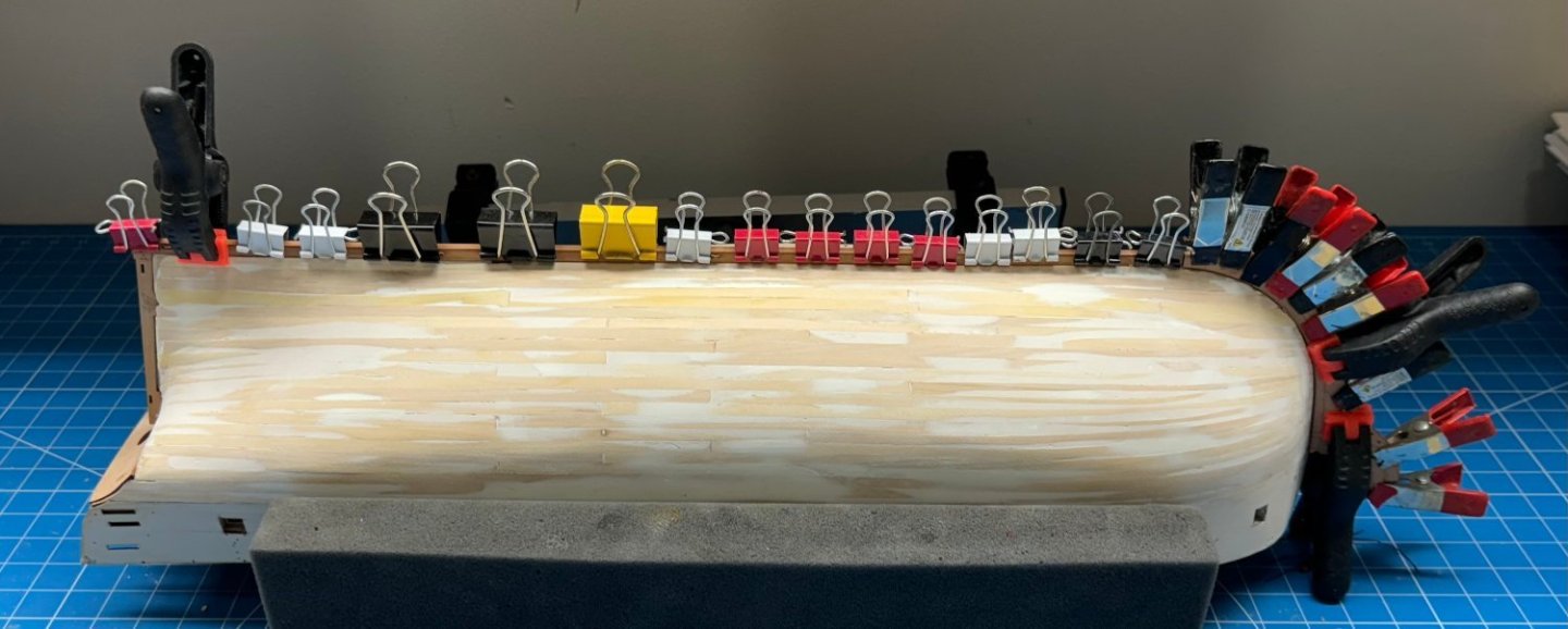
One side of the stem and keel outer "patterns" in place and clamped while the glue (60/40 PVA/Water) sets.
Did I mention you can't have too many clamps?
FYI - I have to sand down the location pegs a bit to get them into the slots. Took the laser char off the edges and rounded one side and they fit in without undue pressure. I used my parallel jaw pliers to push them in until one side was flush then pushed them through the rest of the way with regular pliers.
-
Back to the hull.
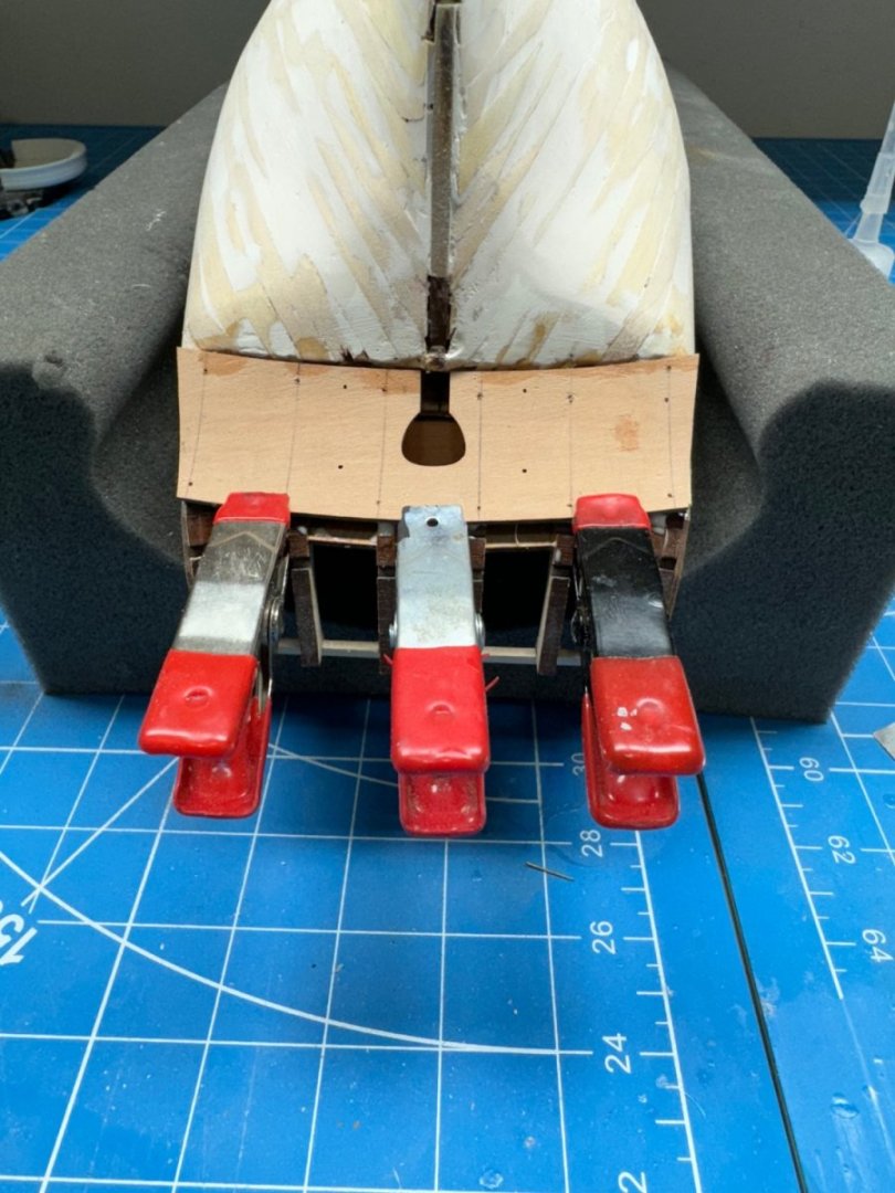
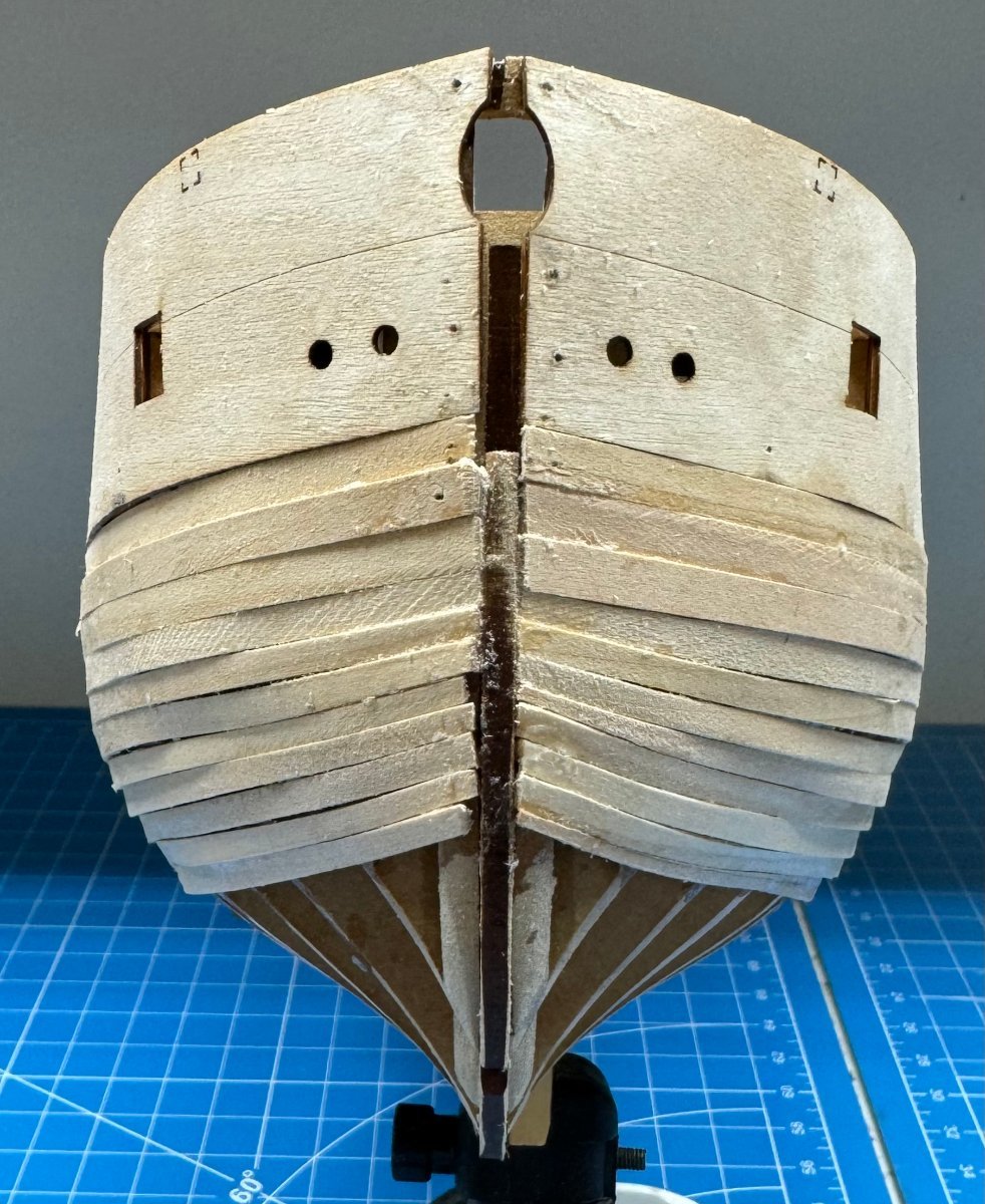
I got the stern transom pattern in place. I did soak and used rubber bands to hold it against something curved. After cleaning up the planking edges I glued the bottom to the hull and held it in place with pins.
When that was dry I added more PVA to the upper parts of the stern timbers and used clamps to bring the counter in contact with the timbers.
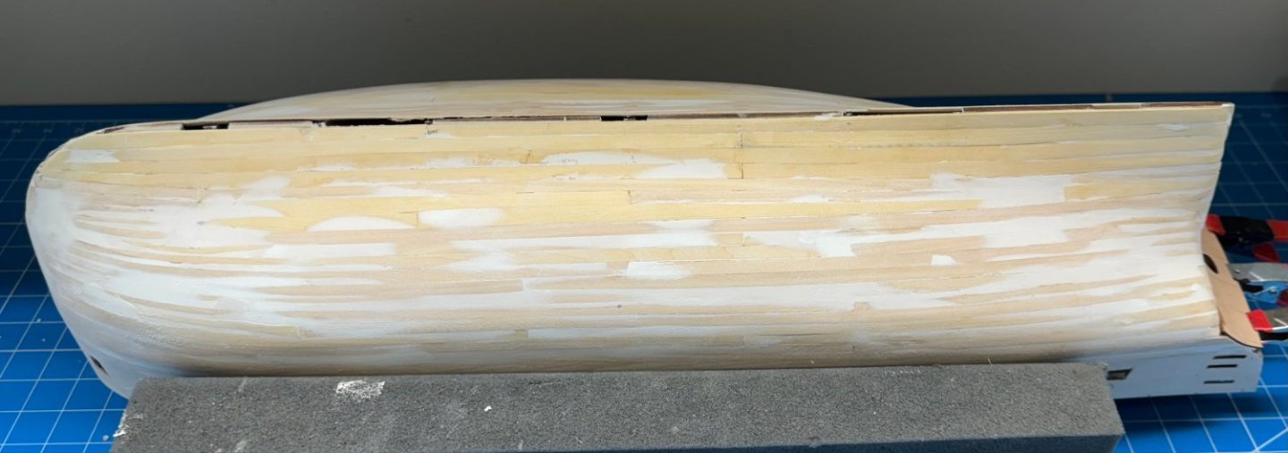
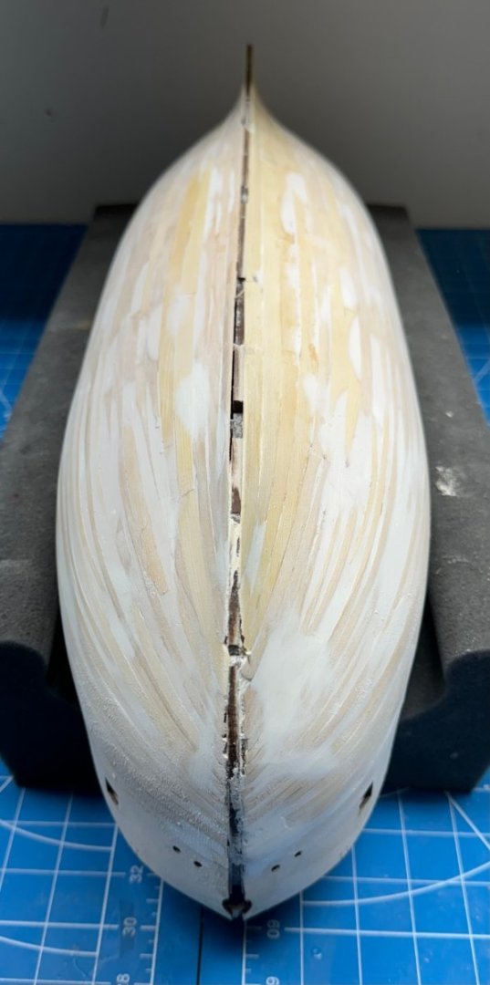
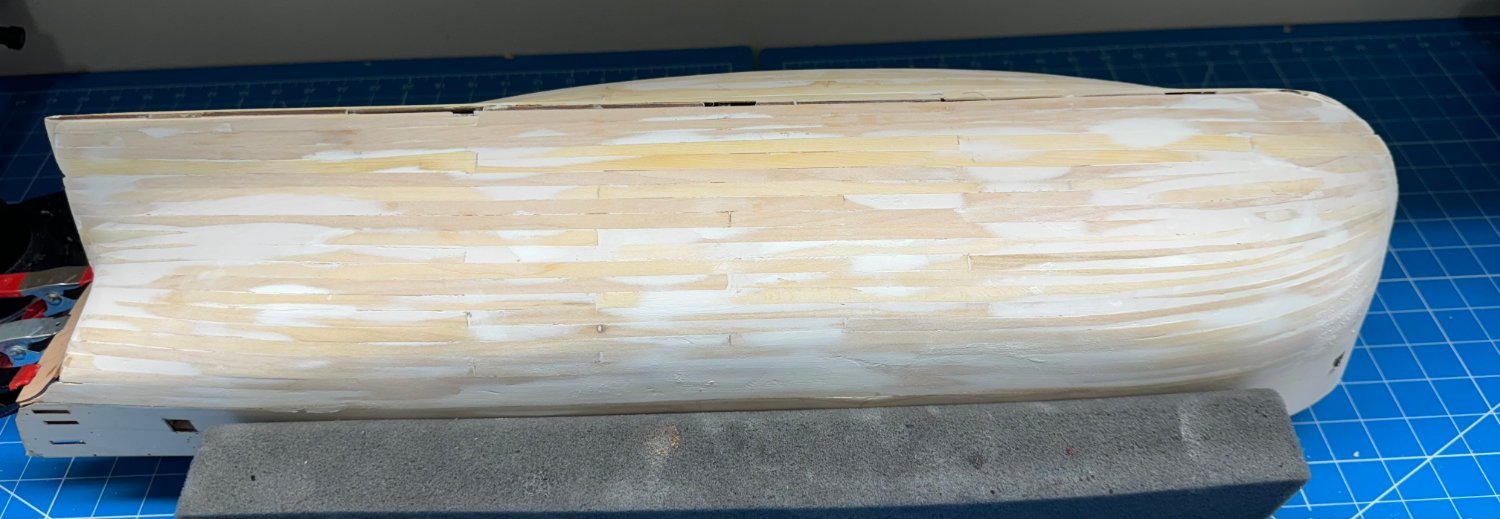
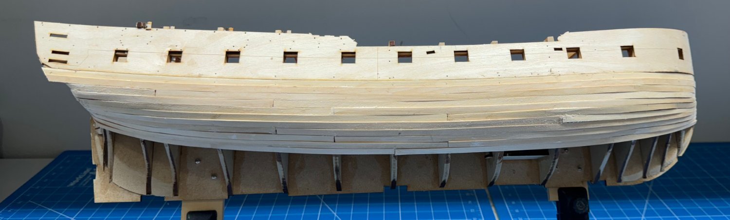
I have decided that the first layer of planking is at the "good enough" stage and am going to proceed with preps for layer two.
Here is what it looks like now - clearly not the best planking job as evidenced by the considerable amount of filler present. Hopefully I will be able to do a better job on the "finish layer "- at least where it will "shows".

- chris watton, mugje, schooner and 2 others
-
 5
5
-
When I get the Vanguard blocks (Monday hopefully) I will post pictures of the Vanguard "standard" and pearwood as well as the Model Expo "Premier" and the Syren blocks.
You can judge for yourself but it will be awhile before you can see them "in use" except for those attached to yards and masts.
FYI - according to the Vanguard website I got the last Sphinx pearwood block set (the site said they had one in stock when I ordered them).
- mugje and Thukydides
-
1
-
 1
1
-
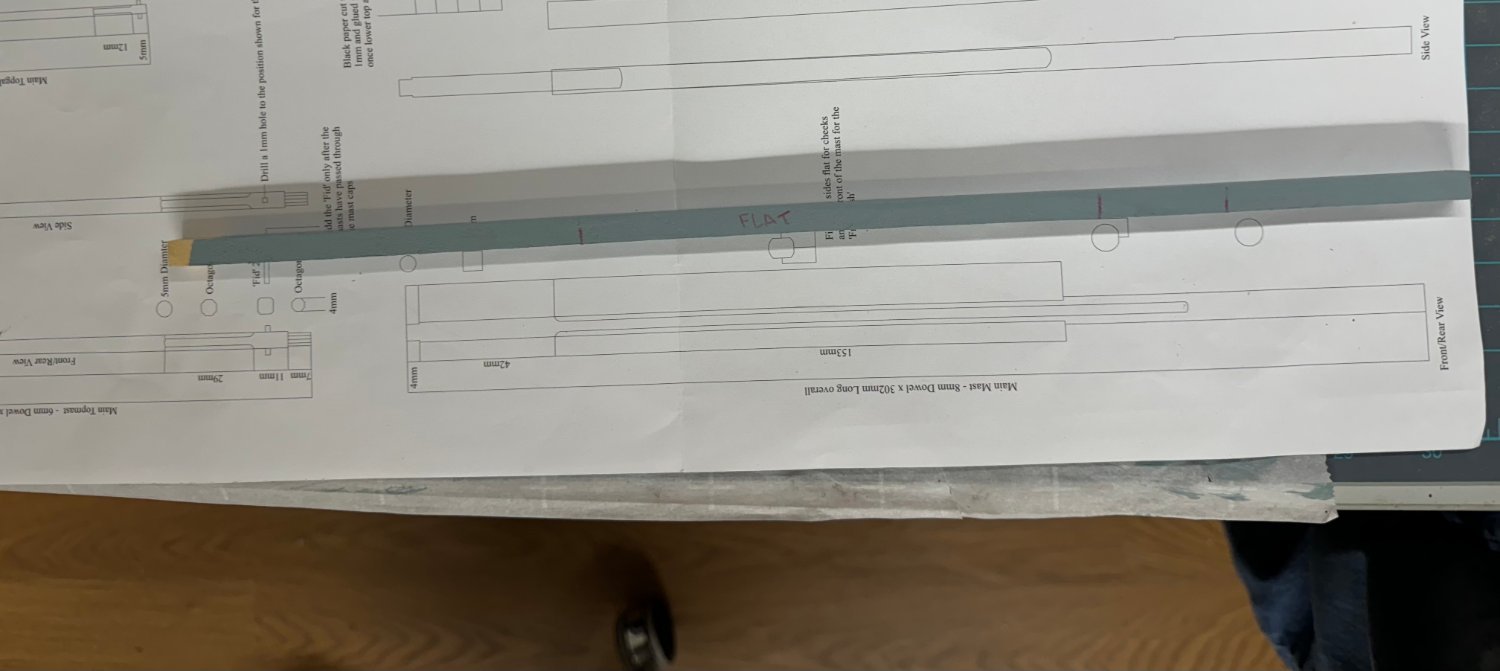
I finally broke down and ordered the Vanguard pear wood block set. It will be here Monday (so says UPS) So I am working the hull (fitfully) and now the Main mast.
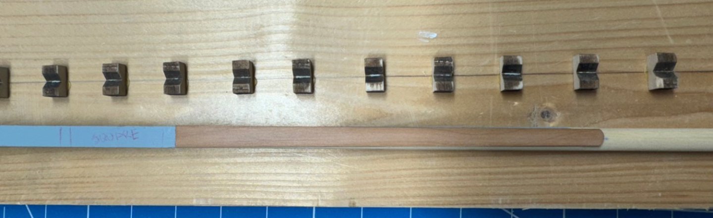
Looking at the drawing I noticed that much of it is flat sided for the "Front Fish" and the cheeks. While the instructions provide a methodology for making the long flat sides on a dowel I thought it might be easier (for me) to start with a square piece and then make it round where necessary.
Unfortunately I did not have a basswood piece 8mm square (or larger) so I cut a piece of Alaskan Yellow Cedar to 8mm square and marked it according to the plans.
 98504568-6DB4-44D6-84FF-7954EADBF3E7_1_201_a.heic
Then I took the easy part - I made the bottom round the same way I did the yards - make eight sided then sand and sand.

Yes it is a little bigger at the bottom but that will be corrected when I do the 220 finish sanding. I measured and it is 7.7mm in diameter at the bottom. Close enough to 8mm (I hope).
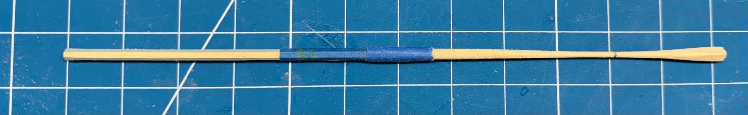
Then on to the front and the flat for the front fish. I used the same technique just only "eighthed" the two corners on the front. It took some finesse but I got the flat mostly just wide enough for the fish. The paint really helps (me) see where has already been sanded.

Now the section of the mast between the bottom of the fish and the bottom of the cheeks needs to be rounded. I put some masking tape over the "fish flat" and then rounded the other sides as usual.

On to the sides and the first "issue". The plans seem to show that the pole is rounded somewhat the entire length of the cheeks. However, the cheeks are nearly 8mm wide at the top making me wonder how I would flatten an 8mm dowel to support the cheeks which are nearly 8mm wide.
Here are the cheeks sitting on the unmodified side of the square mast.
I am tempted to just round off the lower portions on each side of the mast but this will leave the back almost flat as well.
I rounded off the edges on each side enough to make the back not completely flat and then sanded off all the gray paint below the square section so there is no chance of it bleeding out when the finish is applied.
Here is the mast with the cheeks and fish clamped on - no glue yet.
Now on to the square section and cap.
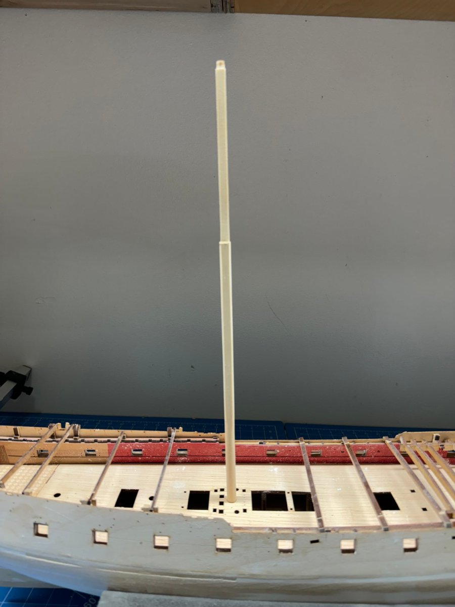
And here is the completed Main mast less the fish face and cheeks.

I am in a quandary about the color of the masts. The dowels provided are of several colors, mostly pretty dark. I already have the Mizzen "done" so I can't redo that without risking destroying some (maybe all) of the other pieces (trestle trees etc.) so I need to stain the Main (and presumably the Fore since it is very similar in shape/construction to the Main) lower section to match the dowel color I used on the Mizzen. May take some experimentation but I have more AYC in the "parts bin".
- KurtH, Thukydides and GrandpaPhil
-
3
-
I have moved the spars to 'storage" since it appears that 4 and 5mm rigging blocks are hard to get from either Syren or Model Shipways.
So back to working the hull and working on the main and fore masts until my "ship (rigging blocks) comes in".
- Theodosius, Mr Whippy and GrandpaPhil
-
3
-
Thanks Thukyides - I made a cursory examination of the pear wood planks this morning and the half dozen I grabbed at random were only off by .05mm from the thickest to the thinnest. I will look themm all over before I start planking.
Since all but the top half dozen (or so) rows are going to be painted (albeit white) I think i can find enough of similar color (and hopefully the same as the two rows supplied in the kit) to cover that area. If not I have a fairly large collection of pear wood I could cut my own planks from although I would hope that would not be necessary on a kit that cost close to $1000.
- Mr Whippy, Theodosius, mtaylor and 1 other
-
4
-
The first layer of the hull planking is done.
I won't bore you with pictures as the planking is mostly covered with filler in preparation for generating a considerable amount of sawdust in the coming days.
Given the experience I am considering doing the whole tick strip planking fan "stuff" for the second planking. I had to take some steps on this round that will not "do" on the next round in spite of much of the second layer is going to be painted. I want to assure myself that I CAN do a credible job when the chips are down.
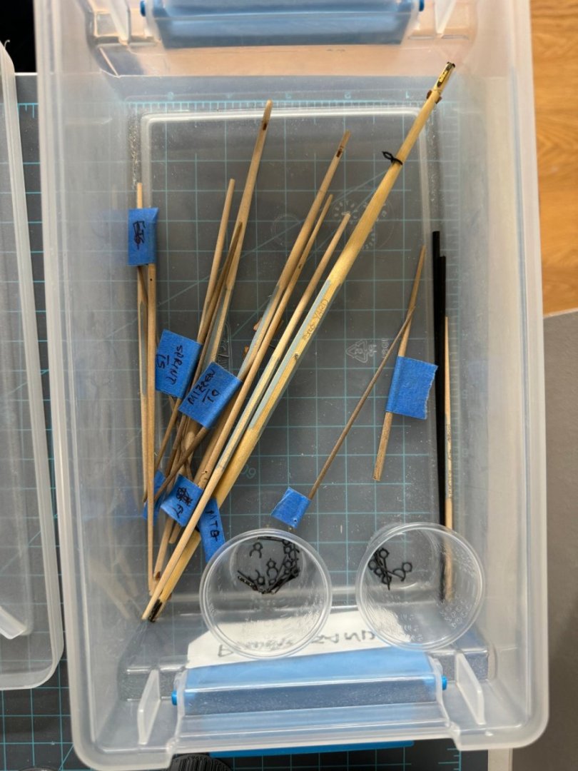
I got all the yard arms tapered and cut to size so in my spare time (sanding is hard work) I can start outfitting the yard arms and just for fun start building the other two masts and bowsprit.
- Theodosius, mtaylor, Thukydides and 2 others
-
5
-
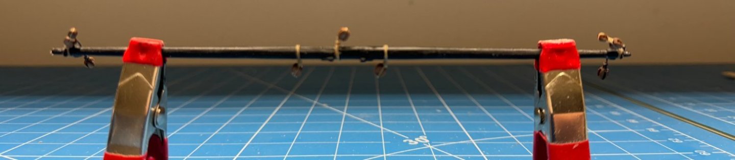
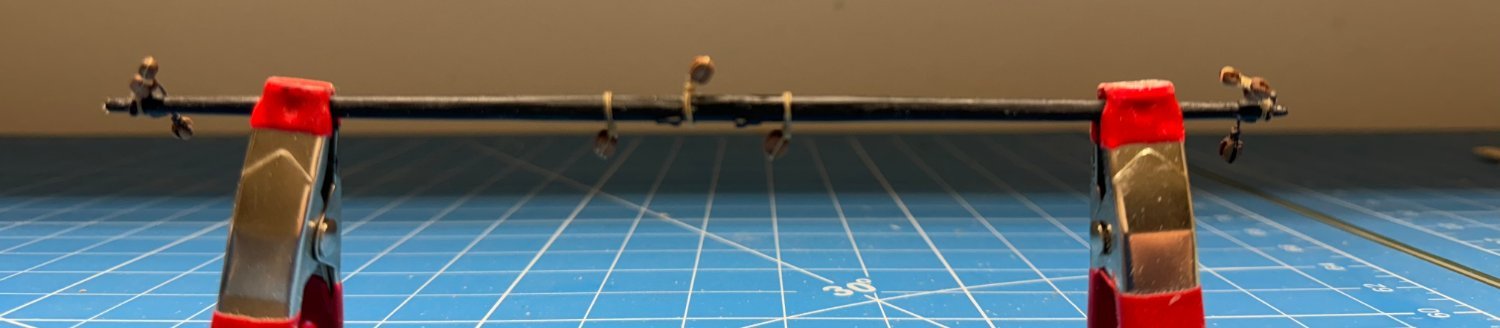
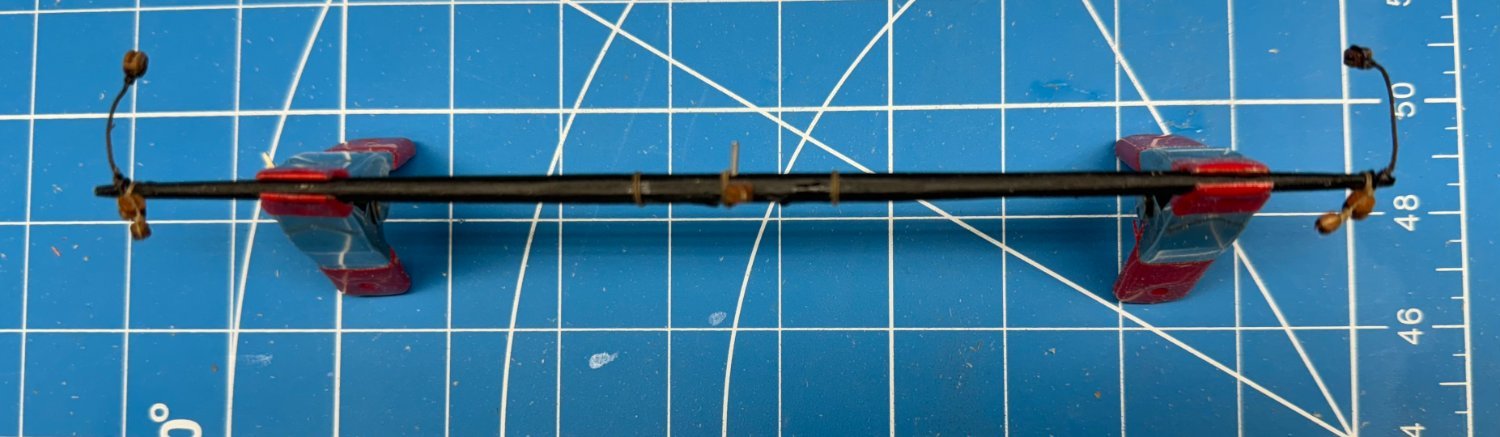
As a test of my material and technique I went and completed the Crossjack yard arm.
on the mizzen mast I used Syren blocks but I do ot have enough of them (and according to Chuck it will be months until he replenishes his inventory) to do all the masts and yard arms so I switched to Model Expo "premium" pear wood blocks for the yard arms.
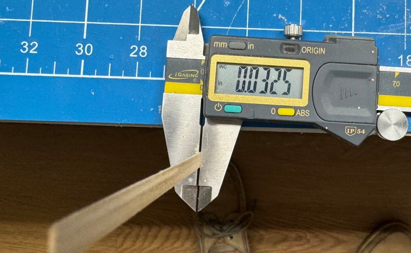
So here is the Crossjack yard with the nine blocks attached and the hole (.039") and wire to pin it to the mast. The wire is not glued in yet - I plan to do all the yards at once using 30 minute epoxy glue so I am reasonably sure the pins will not come out.

- Theodosius, GrandpaPhil, KurtH and 1 other
-
4
-
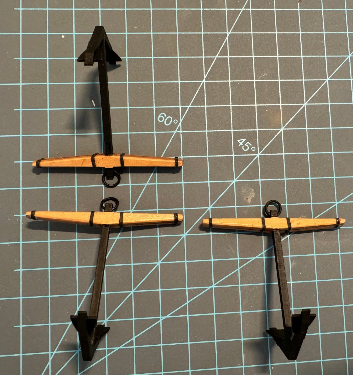
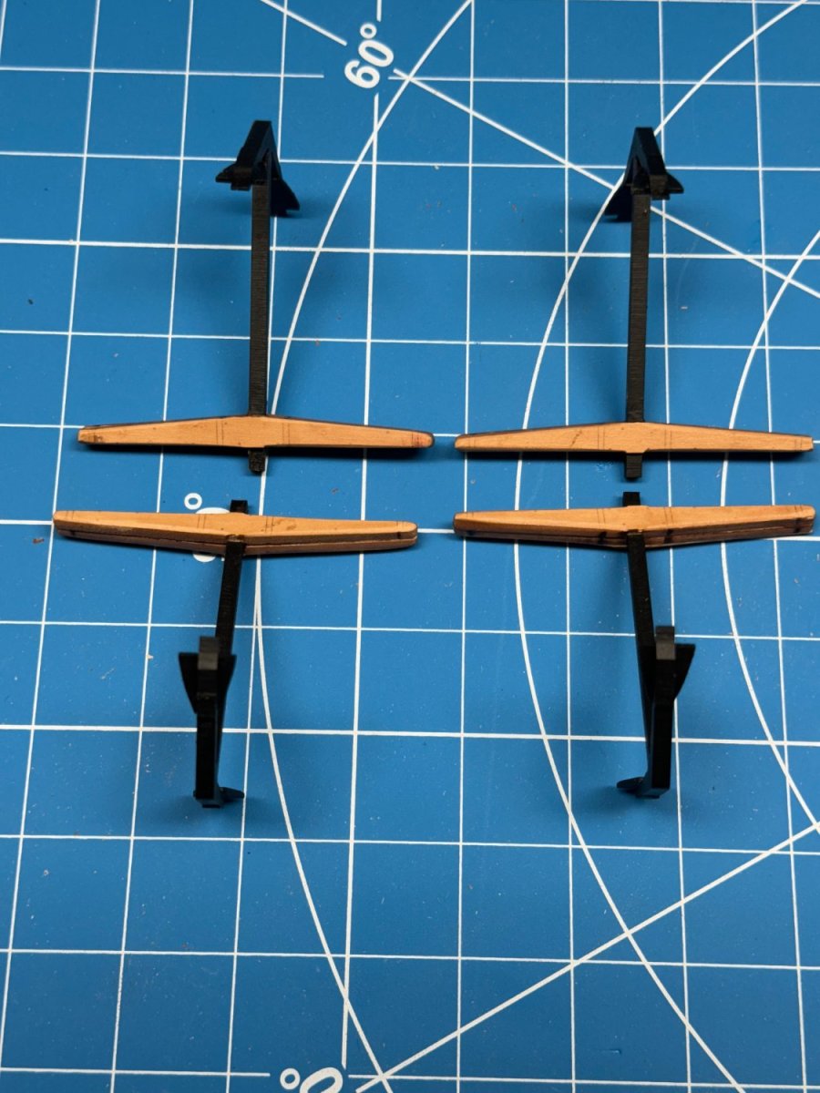
The anchors are finished but not without some drama.
There are no rings supplied for the anchors, the instructions say to use brass wire to form the anchor rings.
I had 5/32 split rings which seemed easier than making new ones. however, the hole in the supplied anchor shank is too small for the 5/16 split ring to fit. It took a #56 drill bit to get the ring in and then the curve of the ring was too sharp to make it out the other side without some effort.
Don't ask me how I know but the MFD material that the anchor shank is made of does not take kindly to being twisted. I believe the issue all started with my making up the anchors. The stock is made of four pieces, two inner that enclose the shank, and two outer finish pieces. As delivered the "slots" in the inner stock pieces are too shallow to allow the two stock pieces to completely enclose the shank without a gap showing near the shank. To get around this I deepened the slot in the inner stocks and narrowed the shank where it fits through the stock. Probably should have just worked on the inner stock pieces and left the shank alone.
Anyway, the fourth anchor is having its upper shank (above the stock) replaced with a custom manufactured piece and will join these in storage shortly.

- KurtH, GrandpaPhil and Mr Whippy
-
3
-
As I mentioned there was considerable difference in the thickness of the material provided - for the record here are two that turned up as I was shaping two more planks at the stern.
-
Thanks Schooner
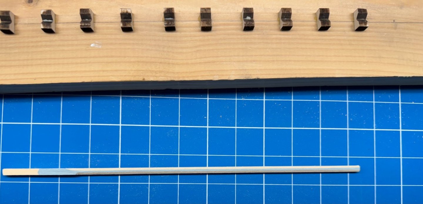
To complete the cross jack yard story
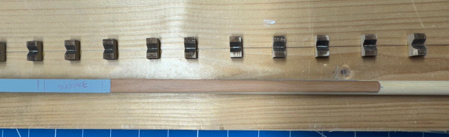
Here is the piece after one side has been rounded and tapered. I used a 120 grit sanding stick to do most of the tapering then switched to 220 for the final. I plan on putting some sanding sealer on before painting. The basswood grain can go crazy if painted bare.
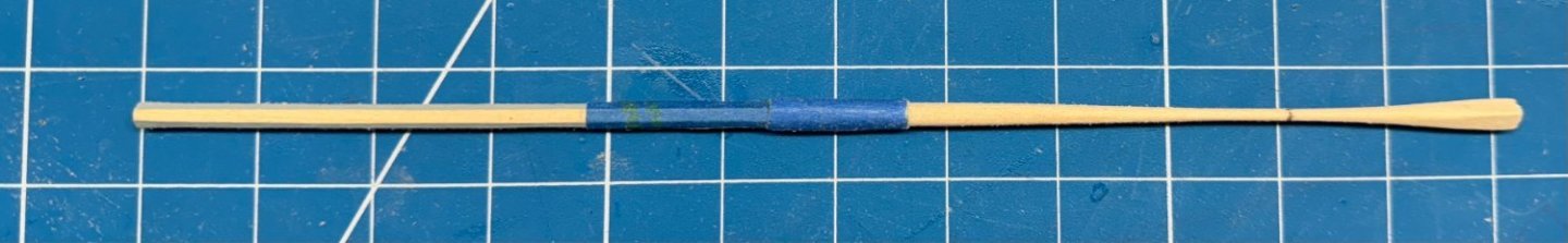
I should have left some "extra" on both ends as I find it hard to not excessively round off the end of the taper if it it also the end of the piece.
And here is the completed yard against the drawing
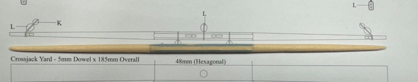
Probably needs some meat off in the middle of the taper but getting a "straight line taper (which is what the drawing shows) takes practice and patience.
- GrandpaPhil, KurtH, mugje and 1 other
-
4
-
More on the yard arms.
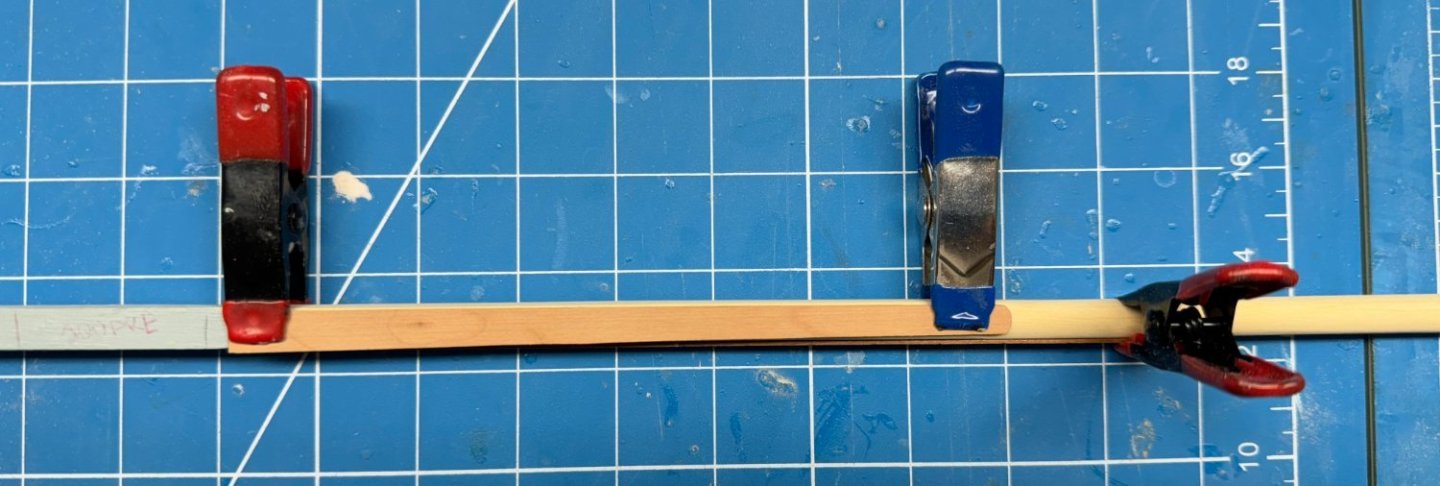
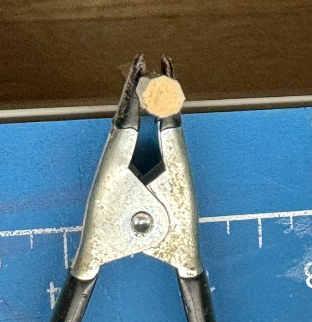
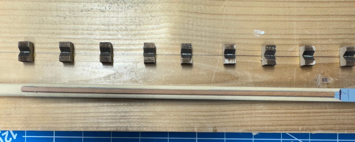
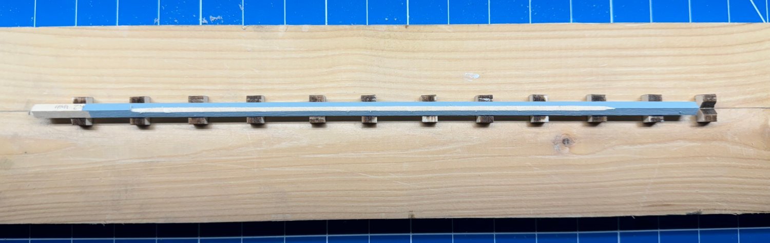
Here is the 4.2mm square "billet in the holder to make it octagonal.
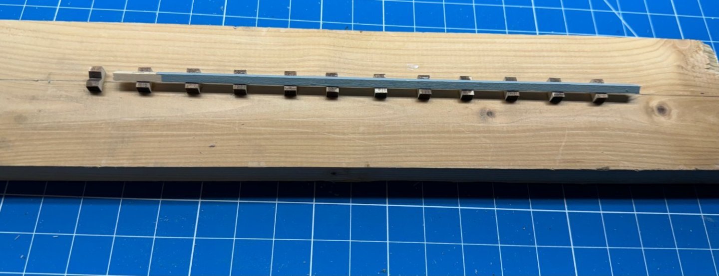
After one pass - the gray helps to know when "enough is enough" and whether the width is consistent from end to end. I make the billet long enough so I can leave a couple of inches at each end untouched. It helps keep the billet in the holder especially when three sides have been done.

And all four sides done.
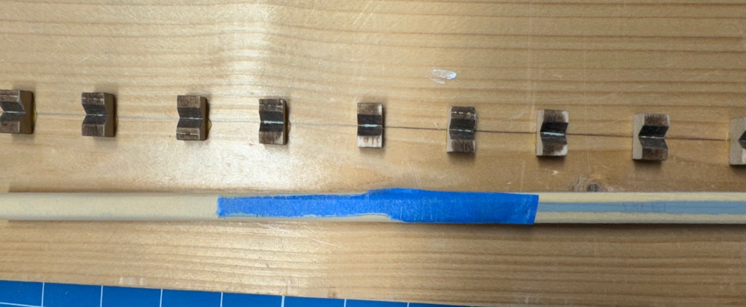
I cut the end off to show that the billet is now pretty c;lose to octagonal. Hopefully it is this way from end to end.
Now I will mask off the center part that will remain octagonal and round and taper the two ends per the drawing.
-
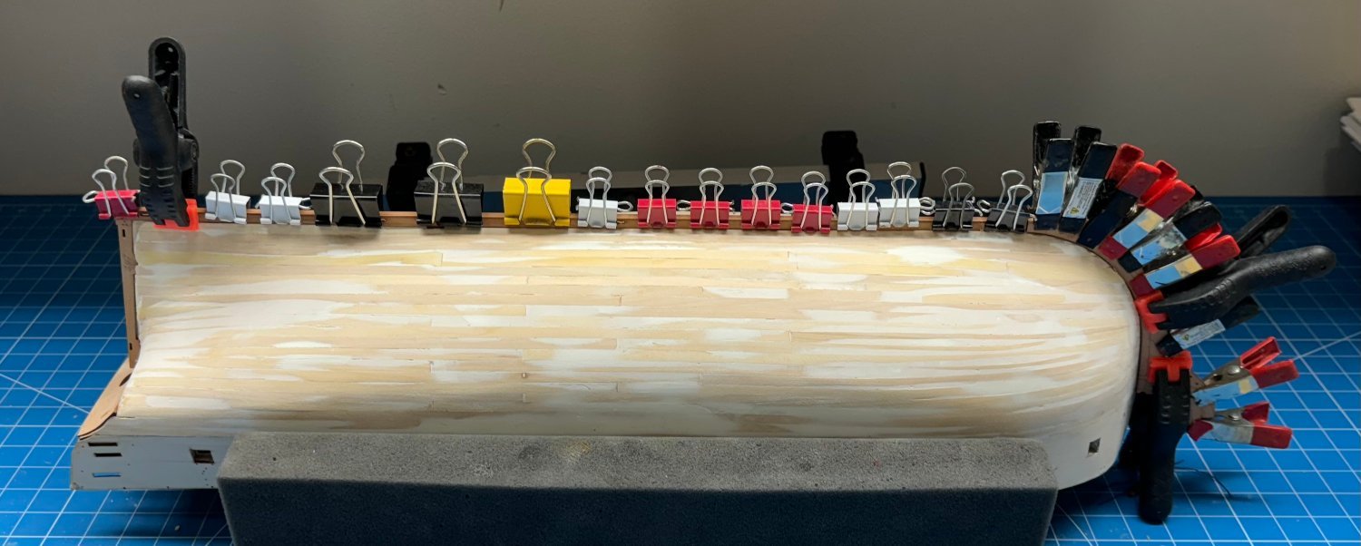
I have no been idle these last few days just not a lot of progress beyond adding more planks.
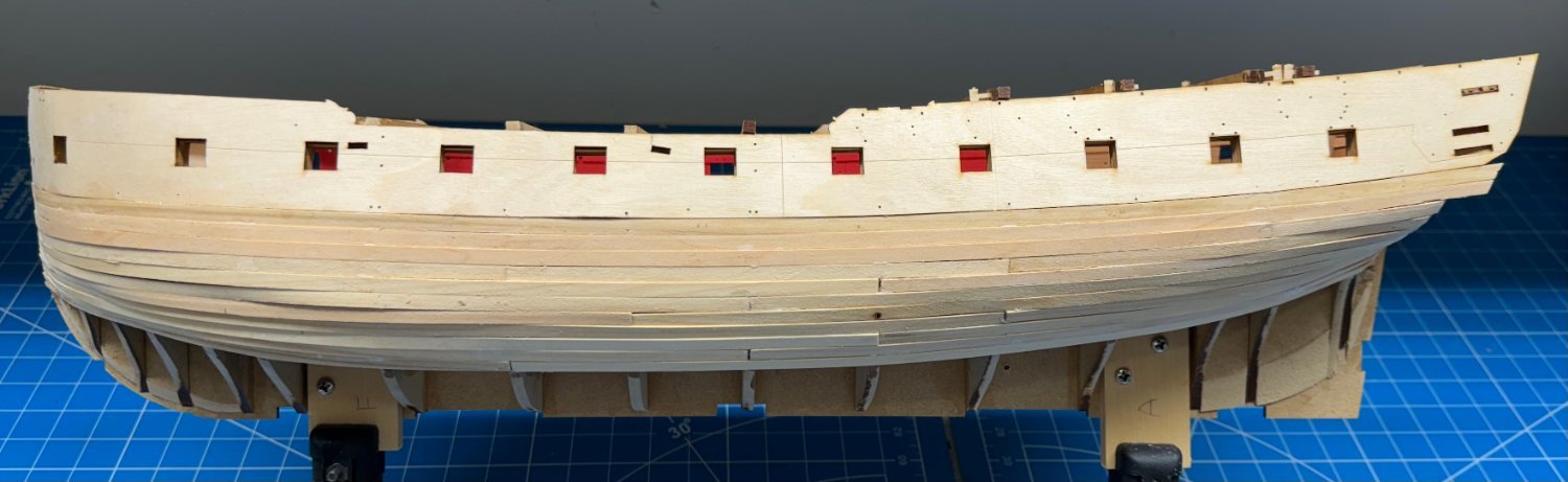
I have 11 on each side now but I think there are at least that many more to go.
Here is how it looks - not the best planking job ever but as the instructions note more than once this does not have to be "pretty" just cover the surface without lumps and bumps, or more correctly in my case no lumps and bumps that can't be sanded out or filled over.


I would note that there is considerable variation in the thickness of the provided material. not that is going to be a problem (I hope) but it does make the job look worse that it might have been with more consistent material thickness.
Any way new subject - yard arms
Since I have the Mizzen Mast almost completed I decided to look at the yard arms to have a new project to work while I continue planking for the foreseeable future.
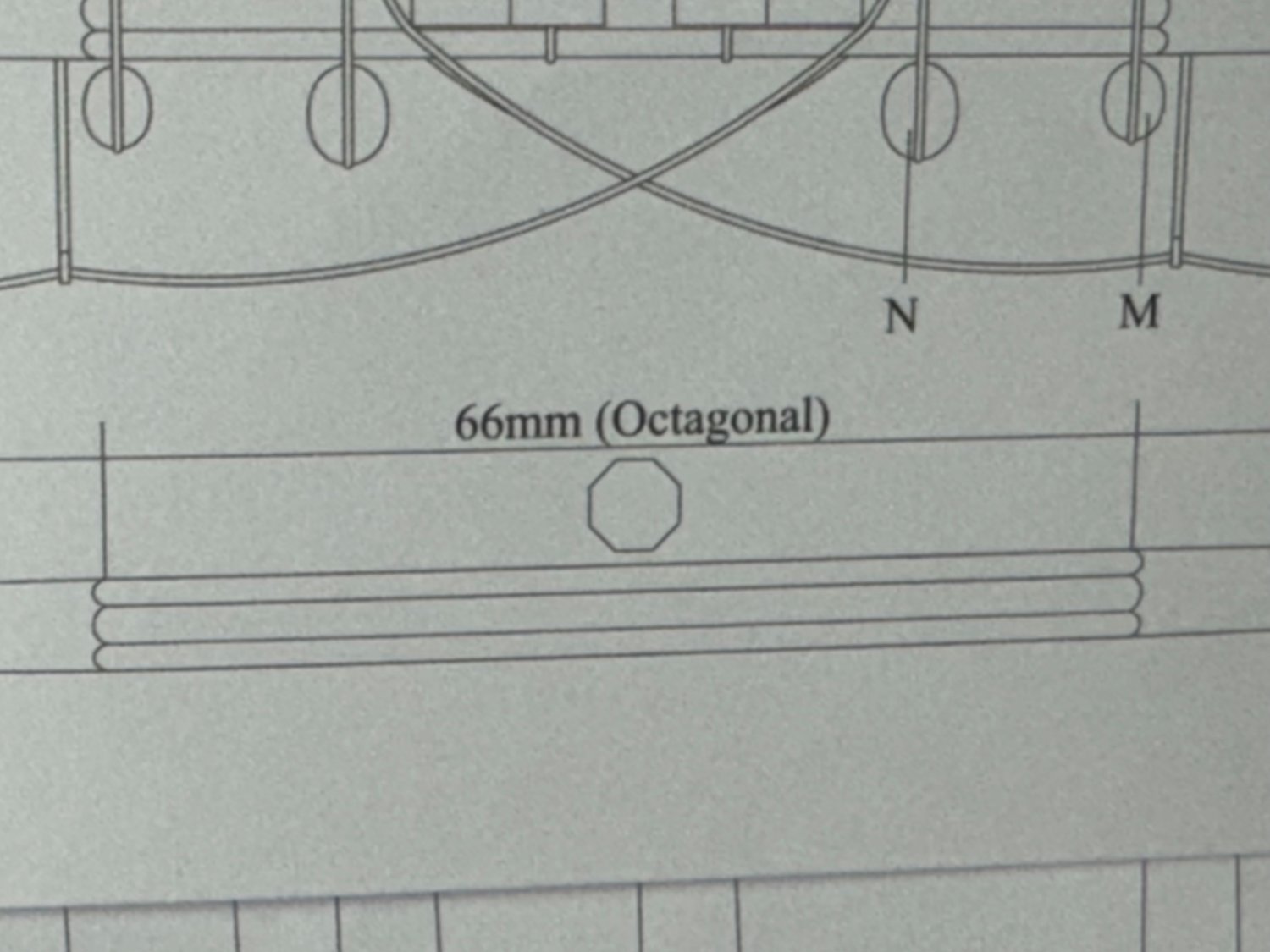
For some reason known only to the shipwrights of that era, the main and fore yards are octagonal in the center while the mizzen are hexagonal. On this model they will all be octagonal - I do not have a methodology for making something hexagonal.
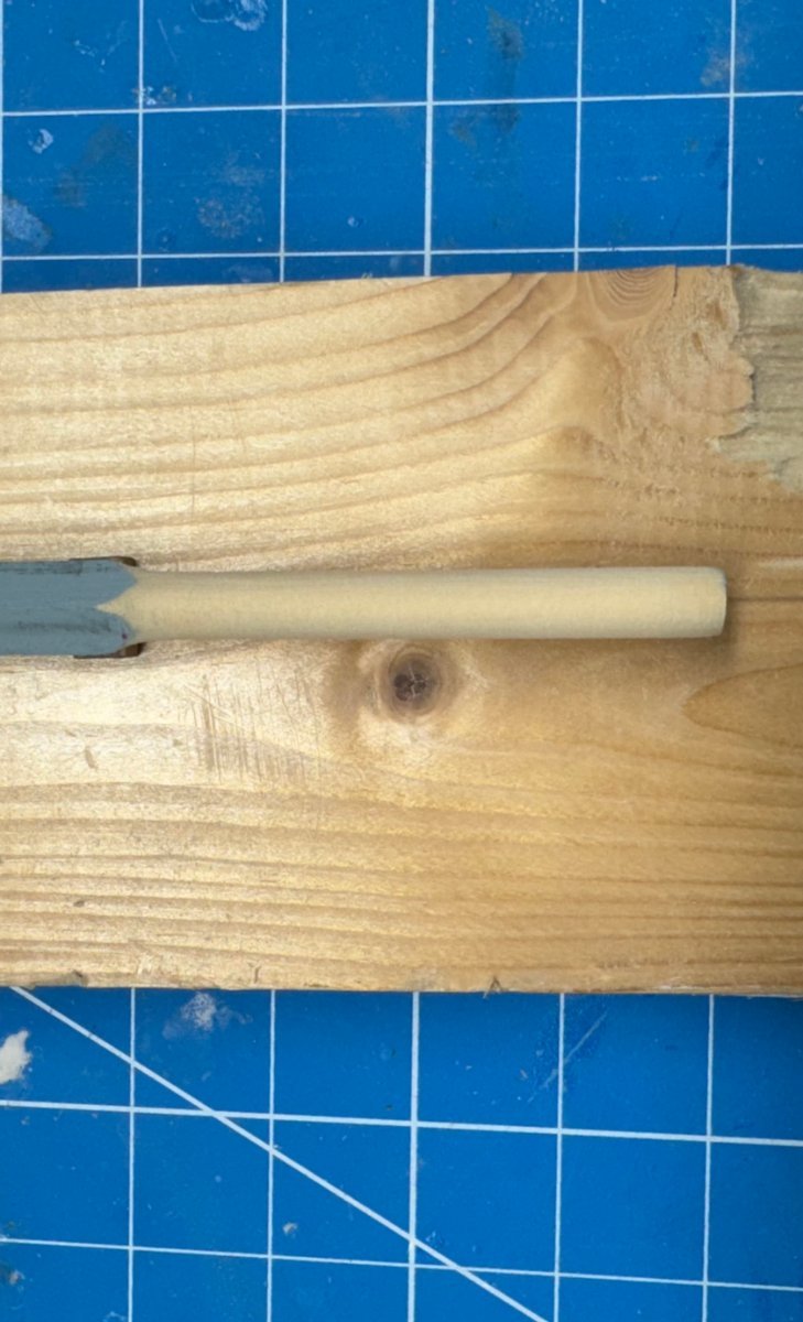
Here the main yard as an example. The starting point, per the instructions is an 8mm dowel. This is to be reduced to an 6.6mm (an obvious mistake on the drawing) octagon.
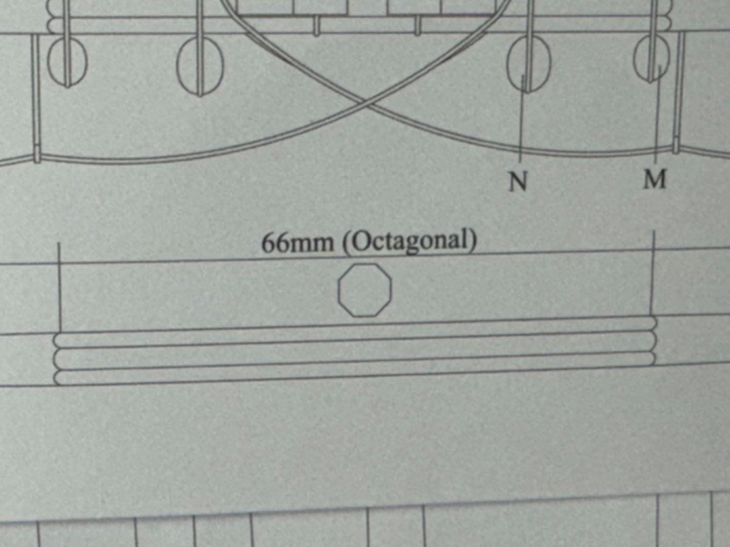
I am not sure I am capable of creating an octagon 1.4mm smaller than the starting dowel and keep all eight sides approximately the same size. I am sure some people can do this but I am pretty sure I am not one of them.
So my solution is to make the yard arms starting with square section basswood (the dowels are pretty hard to boot) thickness sanded to just over the desired octagonal measurement - 6.7mm (or there abouts in this case). I chose basswood because I have it in the "surplus stuff cabinet" and since all the yards are painted black there does not appear to be any advantage dealing with harder woods.
I paint the square section material with gray primer to help show the width of the section being worked better than just the bare wood.
More on this is i get tired of planking.
-
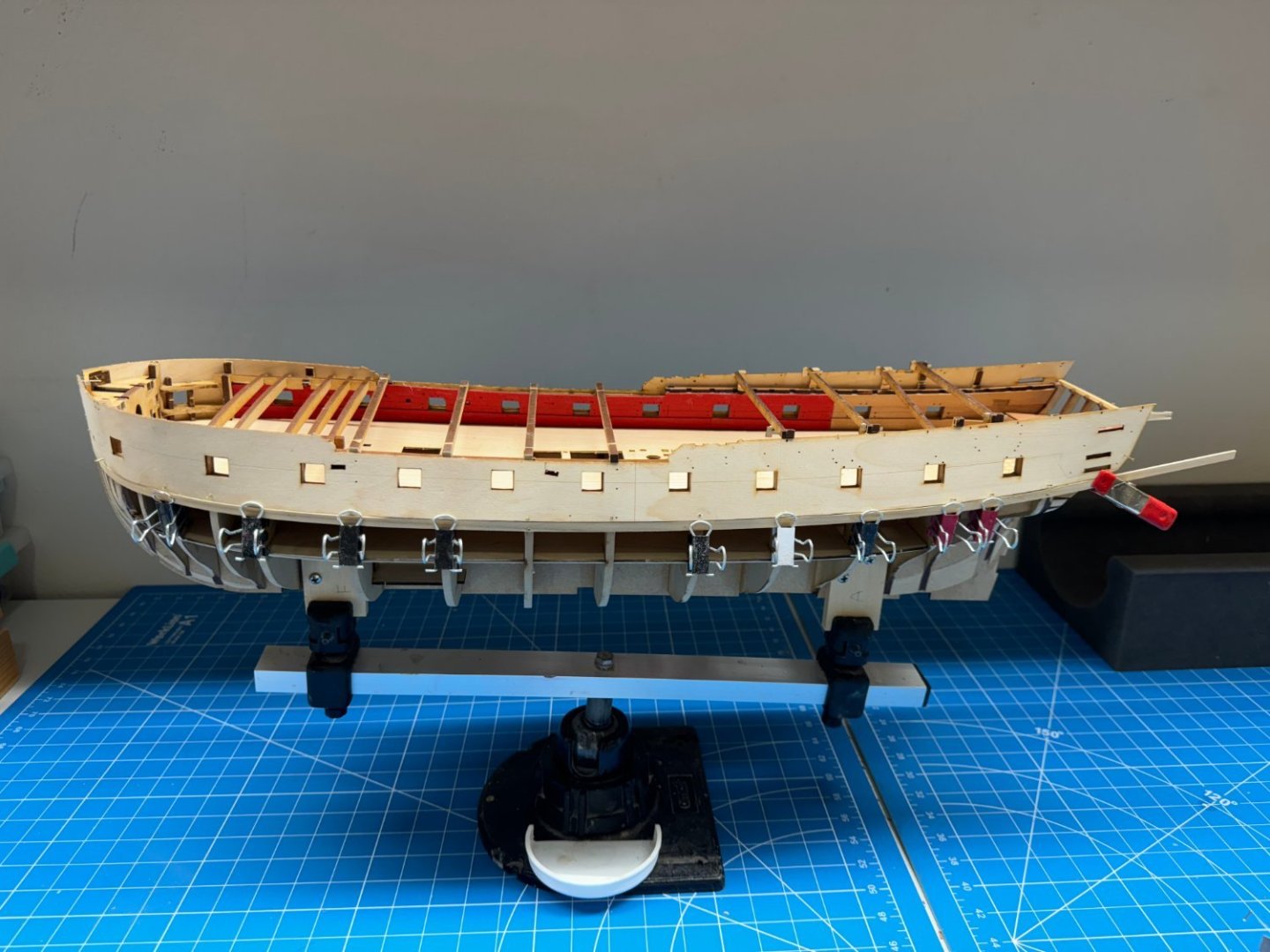
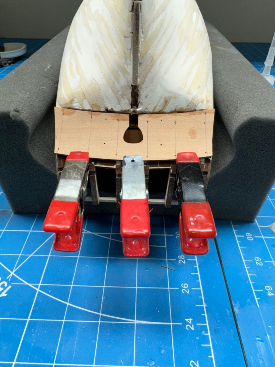
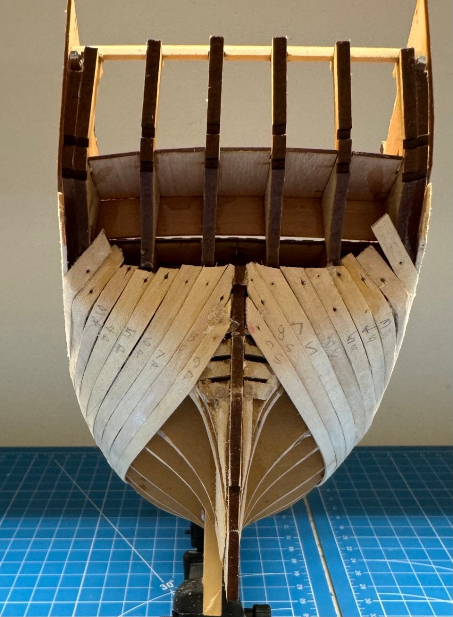
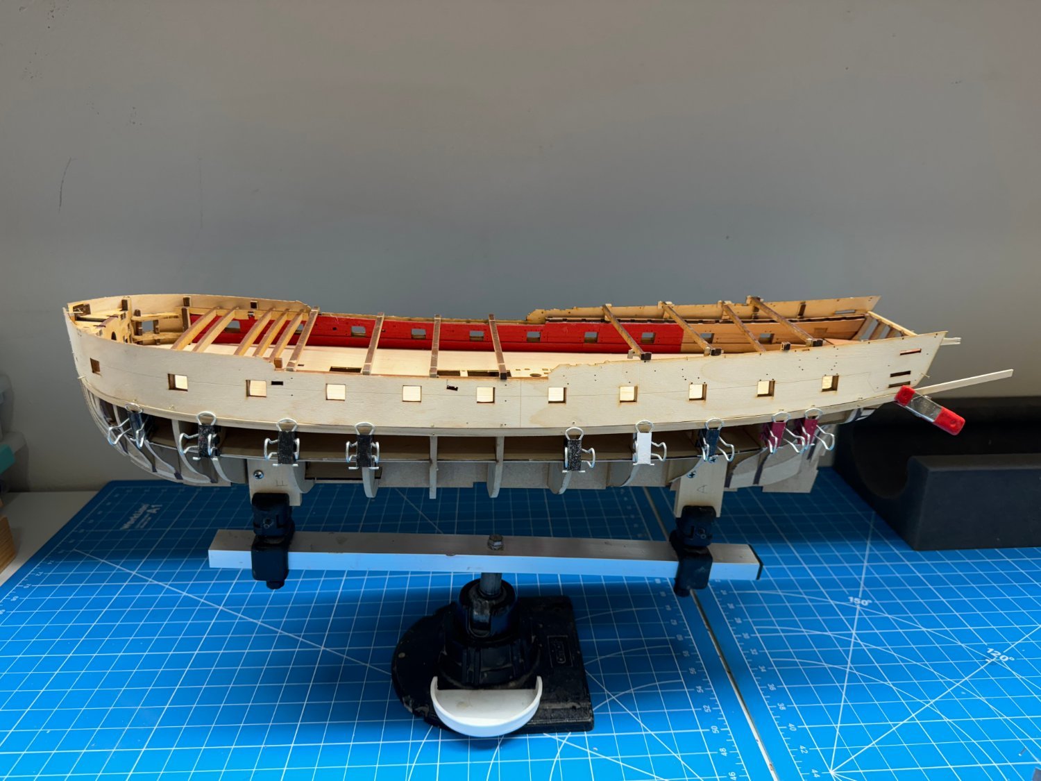
So I decided to use the tried and true water soaking to get the planks "around the curve" at the stern.
Here are planks 3 - 7 on each side wrapping around the stern drying. One by one after they are dry, they are glued (medium CA and dilute PVA) onto the hull and when one stern plank is done I move on to the corresponding plank for the bow. No soaking needed at the bow, at least so far.

Looks like two more planks on each side and then I will be at the stern post where I think the bending gets easier.
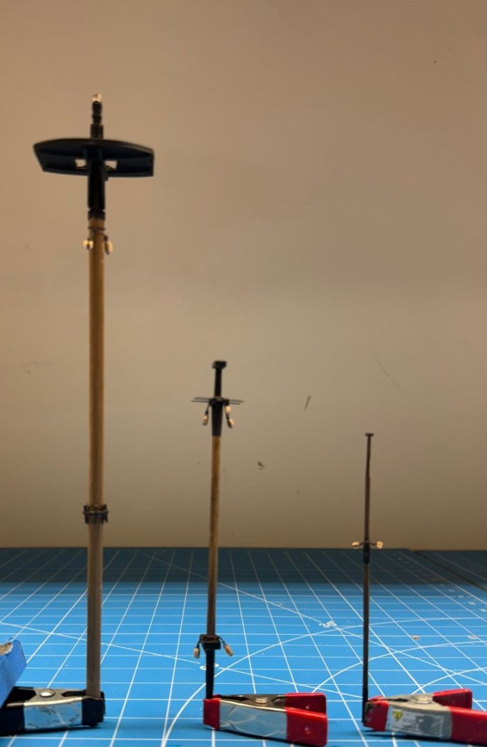
To while away the soaking/drying time I worked on the mizzen mast.
It is now completed, including the blocks but not the railing or stanchions (too easily damaged). I will leave the three pieces unassembled for now as together they make it hard to find a place safe enough to store.
-
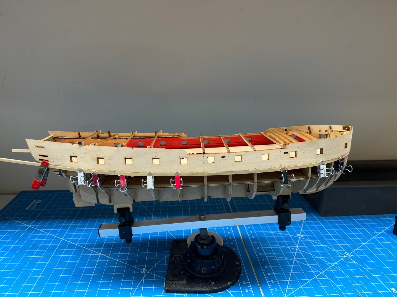
Three rows on each side.
I noticed that in spite of my best effort I did not get the two upper patterns on exactly lined up vertically. hopefully this is not a big deal since this is only the first layer but it will bear careful watching as the next layer is added.
I switched to 60/40 dilute white glue (easier to apply) on the edges and medium CA at the bulkheads for attaching the planks. It is really easy and reduces (almost eliminates) the use of pins.

I have been working the anchors in parallel with the planking.
The instructions say to use black cartridge paper (not sure what that is in "US -speak") but I have some 1/32" (.8mm) black striping tape due for delivery tomorrow which I will at least try to use for the metal bands, here and on the masts and elsewhere the cartridge paper is called for in the instructions.
-
One row of planks on each side.
Using PVA , nails and clamps to keep the planks in place. Am considering goes to medium CA on the bulkheads and PVA on the seams as I did on Winnie.
Plan to do three rows untappered unless something goes awry. Then taper as required. Will do full length planks for these rows then go to half lengths (staggered butts) for the rest.
- KurtH, schooner, Bryan Woods and 1 other
-
4
-
Thanks Don - I opted for the "natural" cabin although the color combo you suggest sounds very interesting for the next project (whatever that might be). While on the subject of cabins I was thinking about redoing the floor using a TBD design printed on some thin but still opaque paper (don't want the kit provided design showing through) and gluing that down like was done with the friezes on Winchelsea. I heard/read somewhere that the real cabin floors (at least on the 6th rates) were painted sail cloth rather than inlaid wood.
-
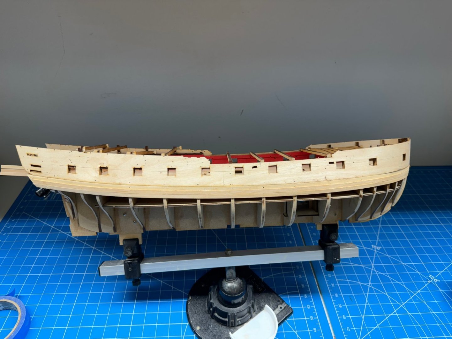
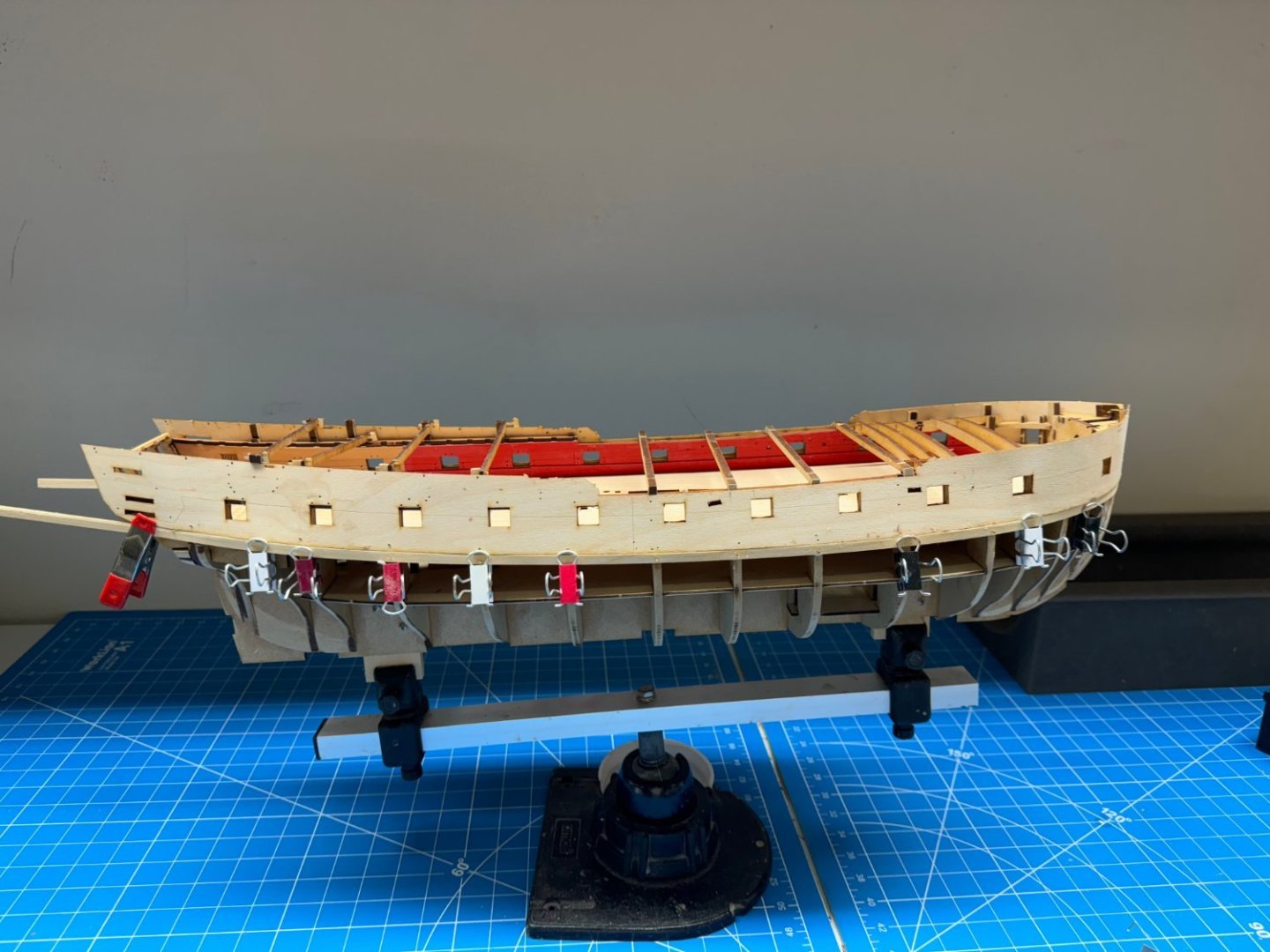
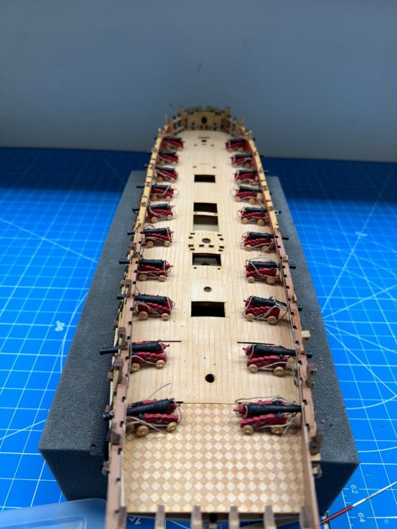
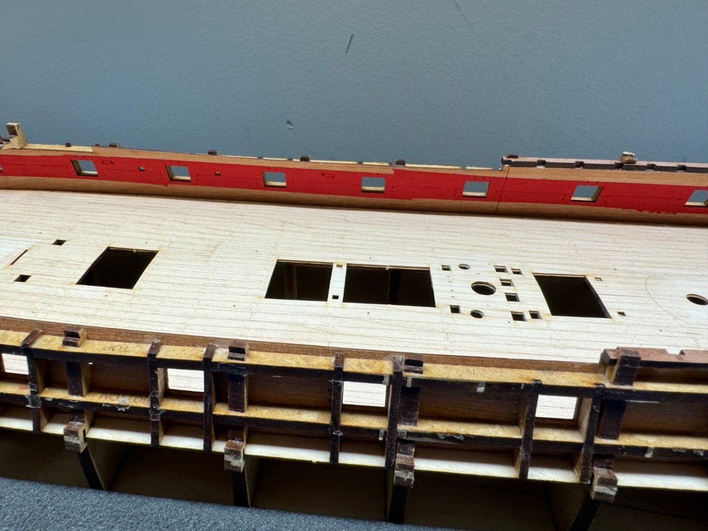
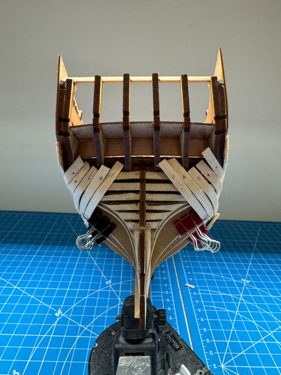
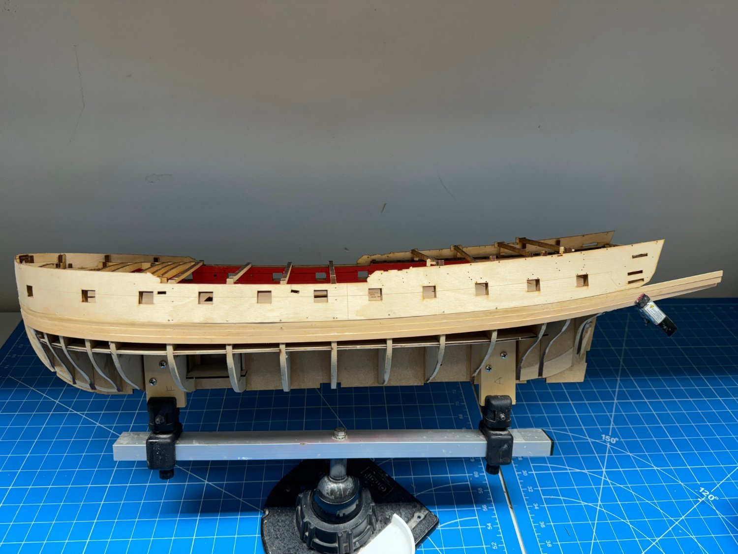
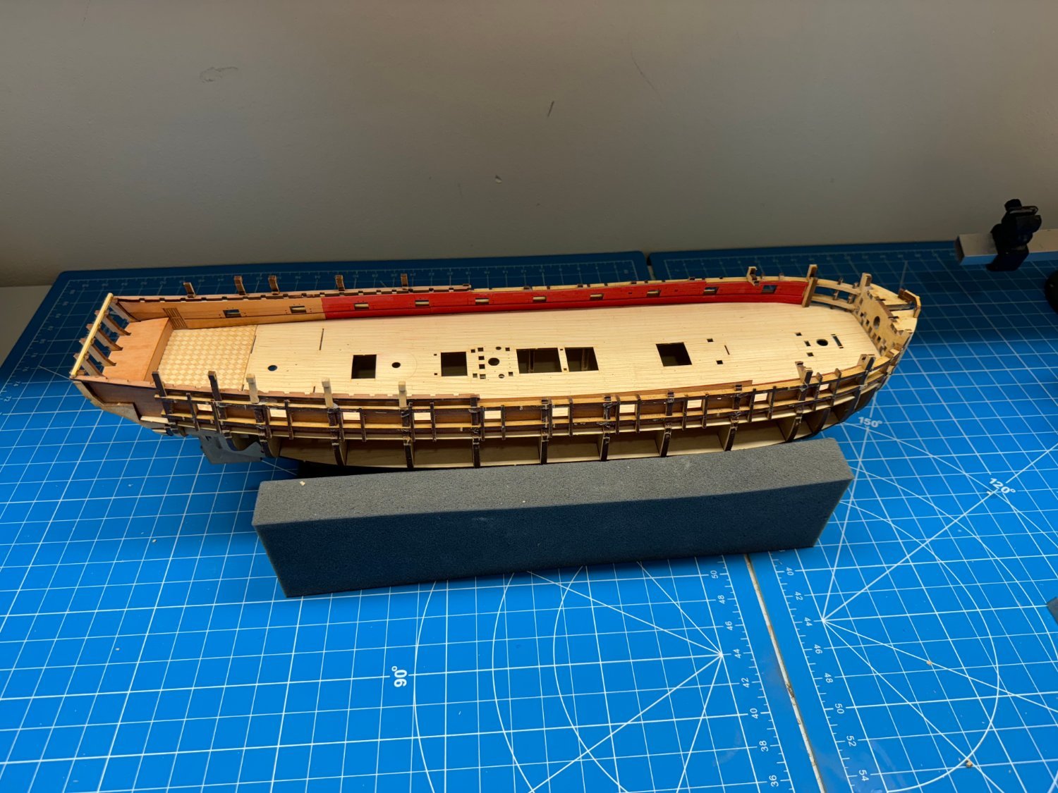
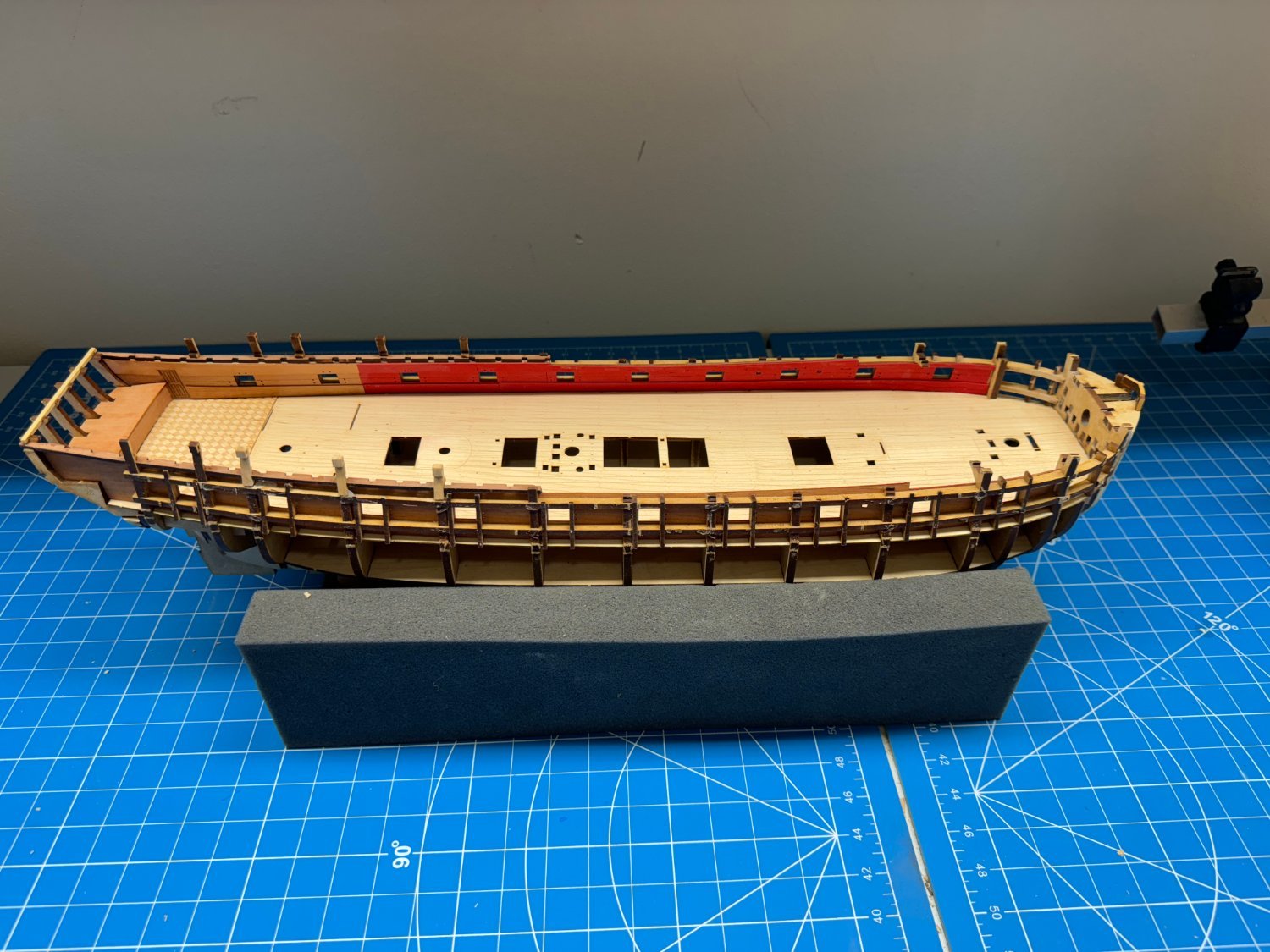
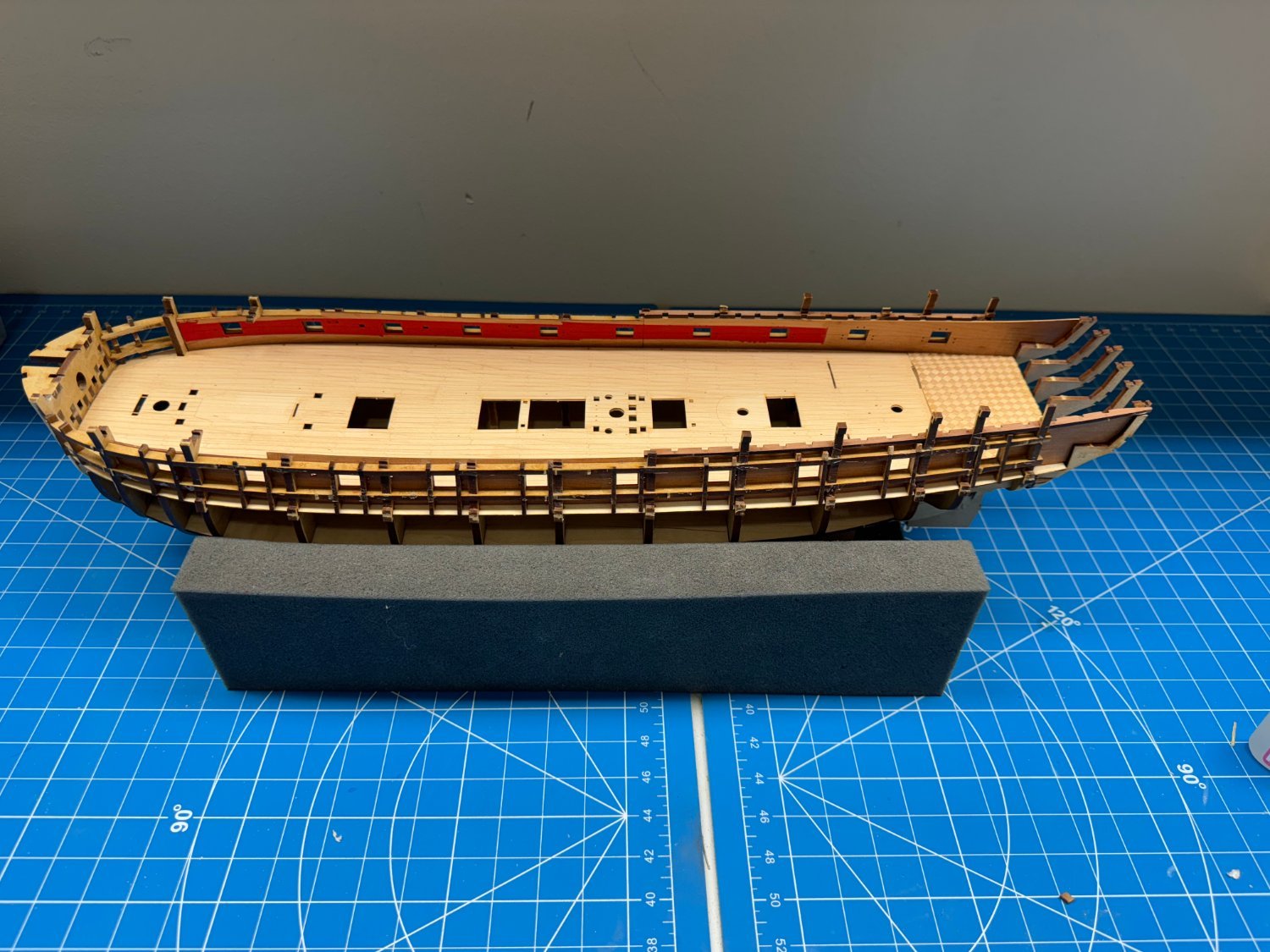
Time to make dust according to the instructions.
All the jigs for supporting for maintaining the hull spacing are ready and all the interior features have been added.
The sharp eyed may notice that there is no spirketting pattern in the great cabin. I got mixed up and painted the rear lower pieces entirely red. Given they are only .6mm thick sanding them would make them paper thin and probably still not get all the red out of the spirketting groves; I decided to make new pieces out of some thin cherry I had. I morn the lose of detail but have no one to blame but myself.


- KurtH, Glenn-UK, Bryan Woods and 2 others
-
5
-
Sometimes it takes (me) several attempts to finally arrive at a modest;y successful approach.
I had to replace three (not two as previously stated - I flunked kindergarten math) of the bulkhead ears on the starboard side.
The first two times I started at the "ear" and worked my way down - this does work, eventually m- I think it took five attempts to get something that could be construed as being "close" to what it replaced.
For the third attempt I started at the bottom, where the bulkhead meets the upper gun port frame and worked up. Turns out this is the way I should have done it from the beginning.
I used the port side bulkhead 9 ear as the template and first cut the slot where the "ear" fits onto the QD beam spacing pattern. Then I traced the outline of the existing ear onto the new piece and shaped it to match. It took more fitting and sanding and fitting and sanding than I care to remember but in the end it came very close to replicating what was on the port side.
Here is the piece I fashioned along side the port side BH 9 ear.
On the inboard side I tried to replicate the "ledge" that sticks out from the ear but did not get it placed correctly and in trying to fix that managed to cut the entire protrusion off.
I decided that rather than start all over I would fashion a separate piece to become this ledge and then glue it on separately.
Here are the two pieces - the "ear" and the "ledge" glued on to the starboard side BH 9 above the upper gun port frame.
- mugje, Bryan Woods, Gregory and 1 other
-
4
-
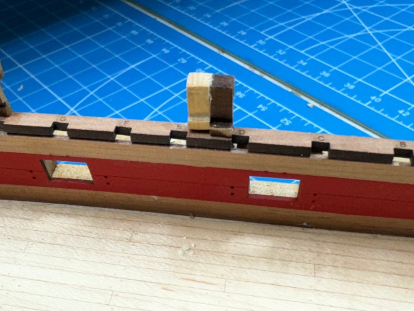
So to "fix" the two bulkhead "ears" that were broken I decided to try and make an entire new "ear" from the top of the upper gun port frame rather than try a glue the missing piece onto what remained. As you would expect it broke at the narrowest point thus making getting any kind of glue to "hold" a challenge.
As with the stern timber spacer I used boxwood which I sanded down from 7/16 X 5/16 to about 5/16 square although I used the dimensions of the remaining piece as the "benchmark".
Here it is glued into the gun port framing and the bulwark. maybe not as straight as I would like but I think it serviceable.

I clamped a ruler on top of the two "ears" fore and aft of this one to set the height.
Here is the view from forward.
I drilled out the center rather than trying to get to the rectangle because I was beginning to get nervous about stressing the piece. If I had been smart(er) I would have created the opening before forming the rest of the piece. I will do that on the next one which is two bulkheads forward of this one. I do not know what purpose that opening serves but will find out eventually.
On the good news front now that the gun deck is in place I pulled out my already made (although slightly taller and longer than the vanguard versions) of the cannons and they will fit through the gun ports, without any wheel sanding. Back in the box they go along side the ships boats for use somewhere in the distance future.
-
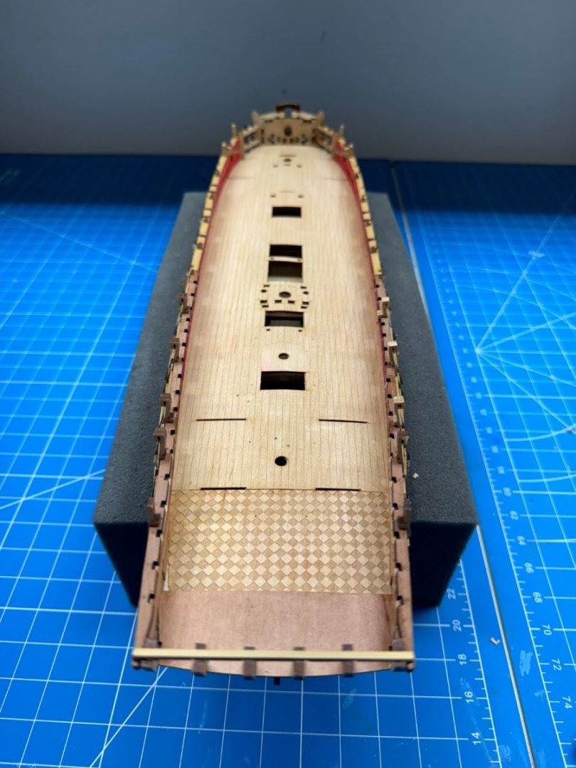
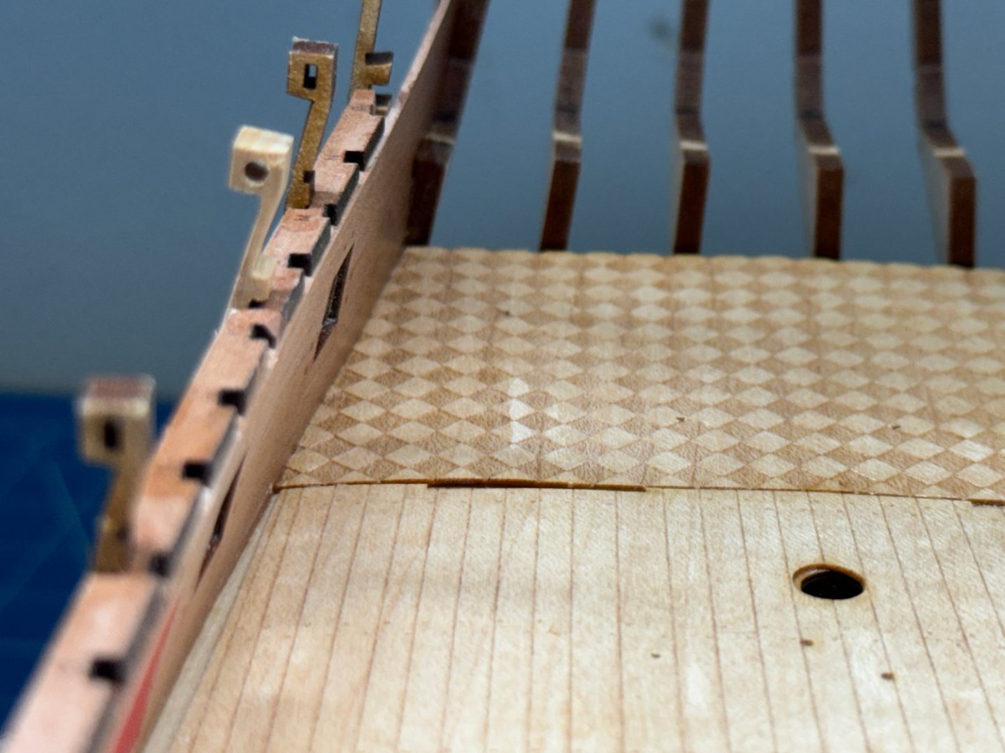
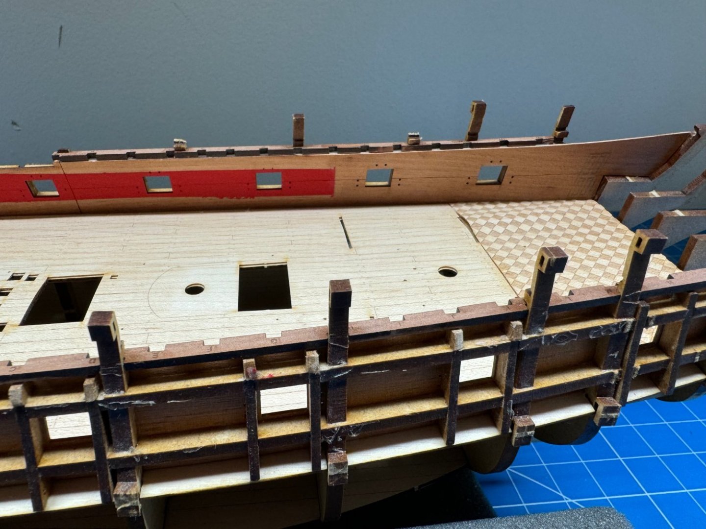
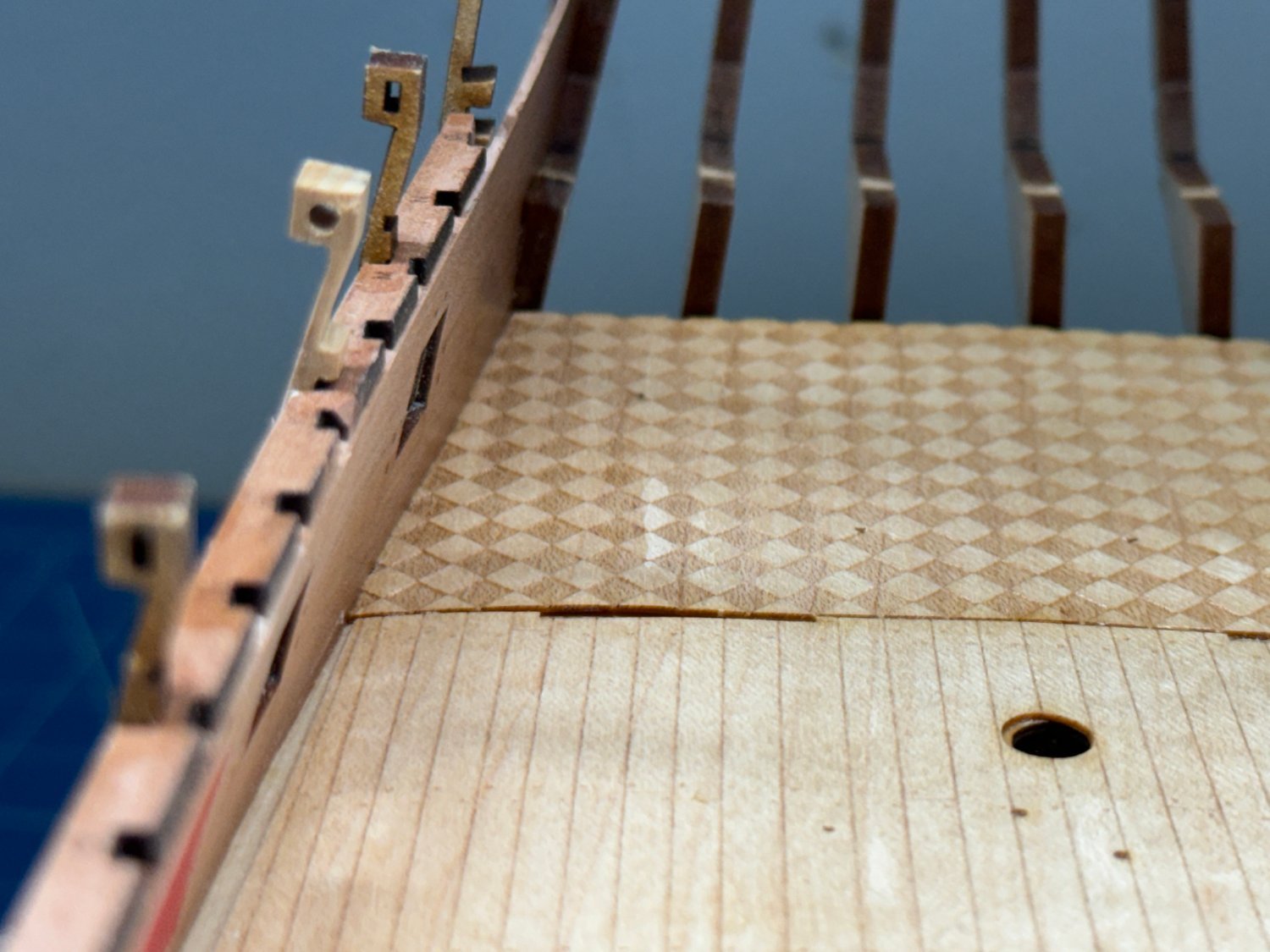
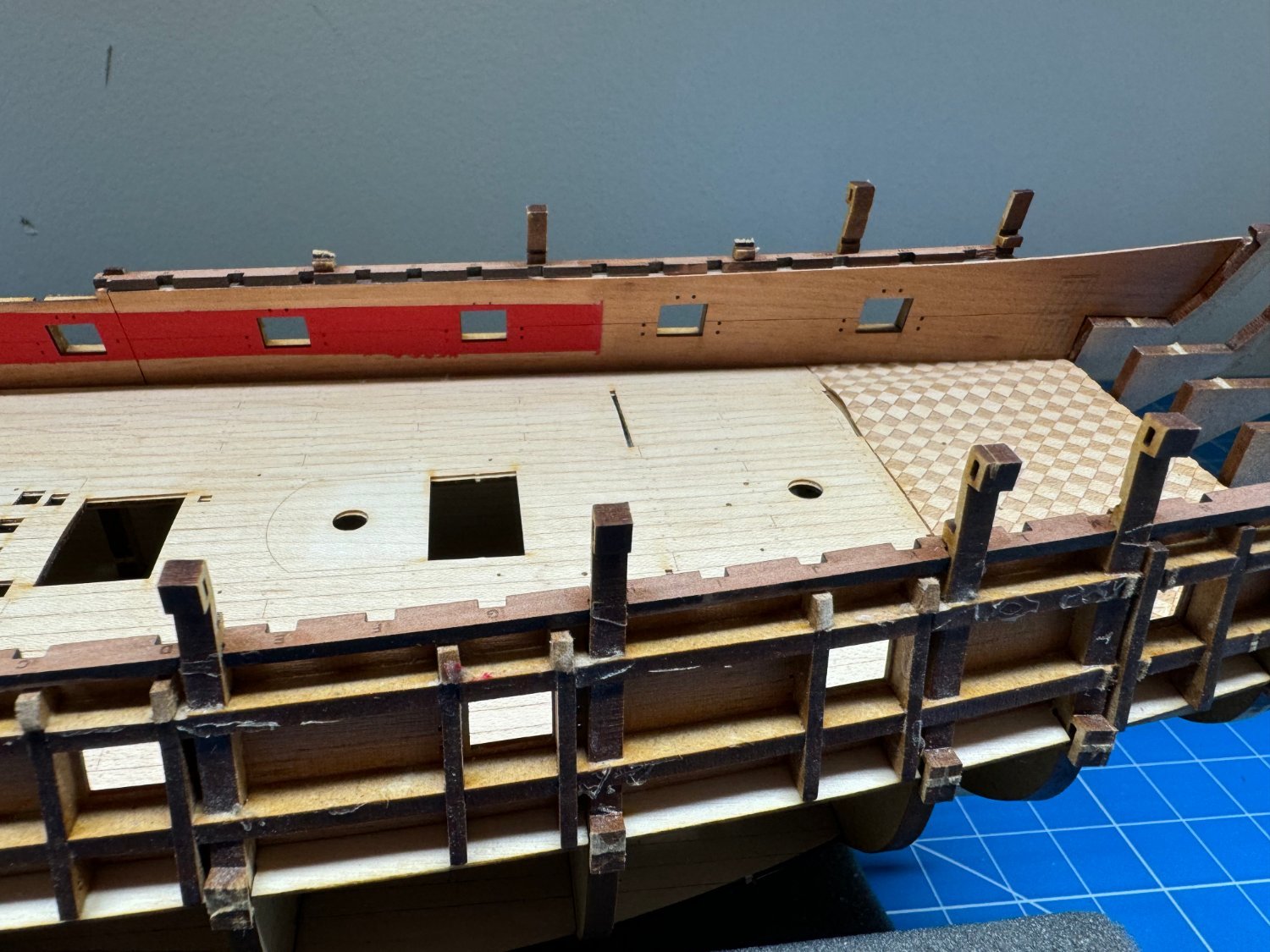
Deck completed although I did have to re-glue both outside edges. I guess my glue painting party was not all that successful.
After I painted the bulwarks I added the checkered floor and then put a coat of Polycrylic Clear Matte (PCCM) on.
I am going to add another coat of PCCM and then install the new stern timber connector and the missing piece of the QD Beam Spacing Pattern.
And then on to the spriketting and deck clamps; which have also been painted.


-
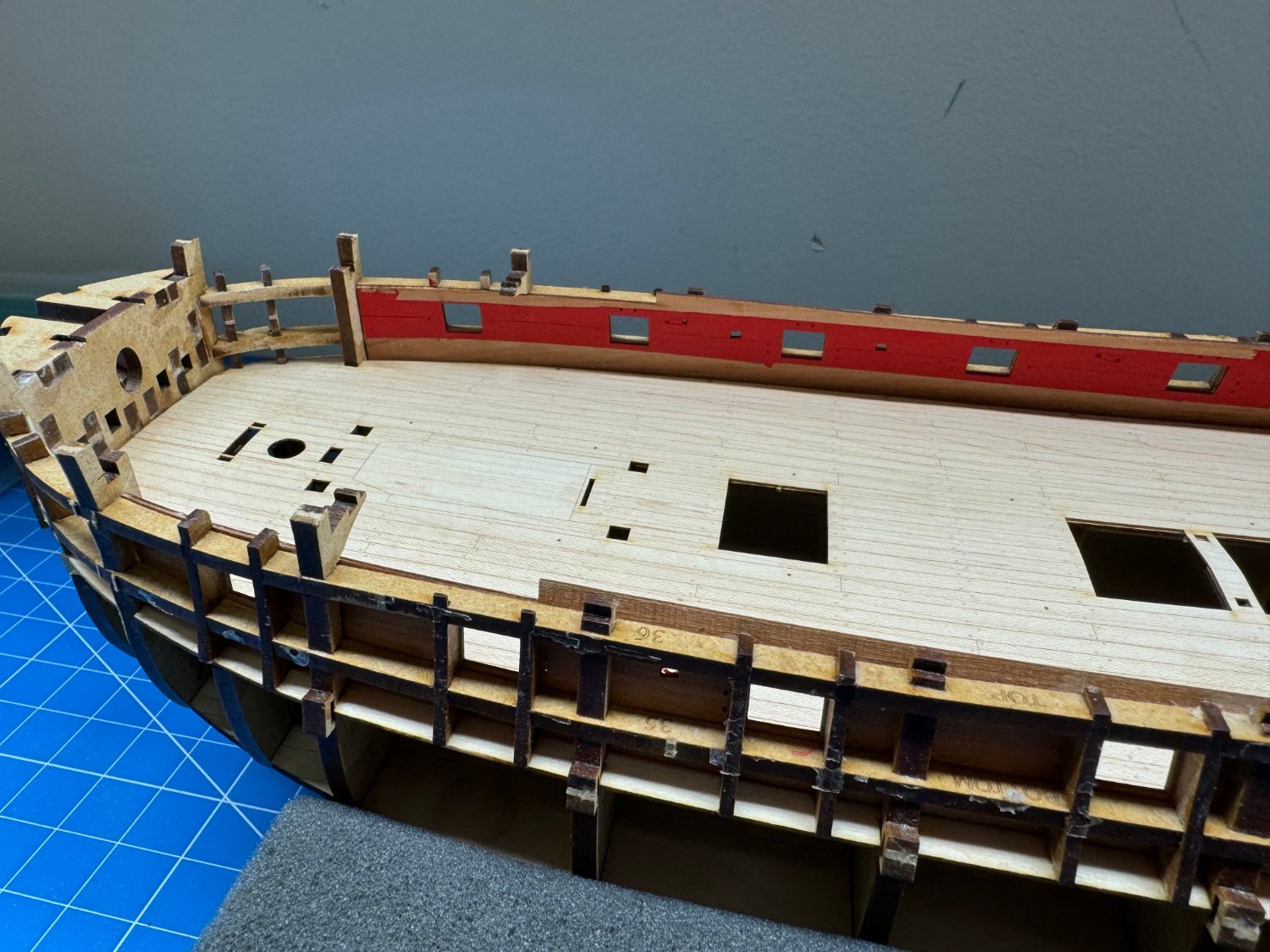
I did not mention it at the time but the switch back to the foam cradle was the result of the Amati clamp actually falling over as the mechanism the provides the swivel feature was not designed to handle the load of four machinist blocks if they are not very carefully balanced.
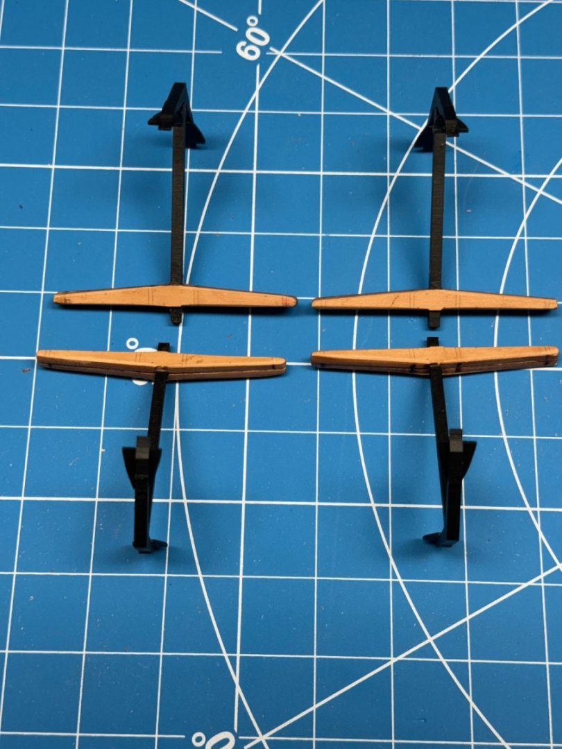
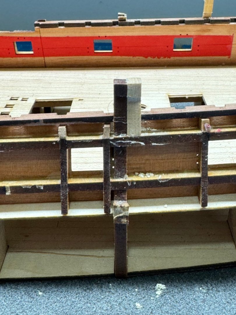
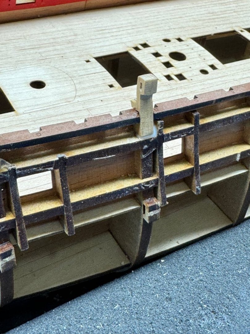
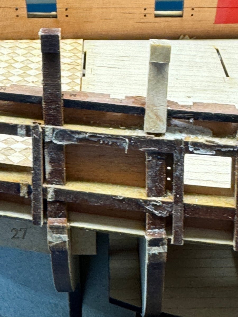
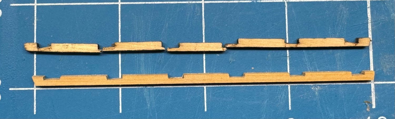
The fall was not very far but it was not without damage. Principal among those was it broke the connector that runs across the top of the stern timbers (part #41 for those following along).
I assume based on my experience with Winchelsea that this is an important piece keeping the stern timbers properly spaced and proceeding without it is probably not a good idea.
I measured one of the pieces and took a piece of boxwood and sanded it down to the same dimensions.
Then I carefully filed the slots into the boxwood using the surviving pieces as the template. Luckily one of the fragments had two slots in it so I used that to get the spacing.
Here is the finished product and the "template".
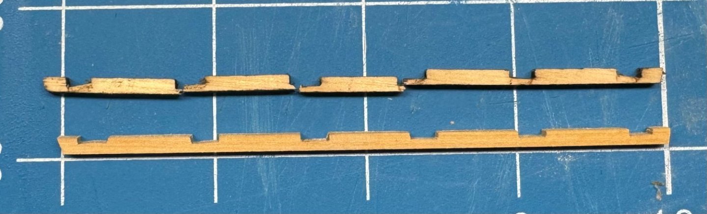
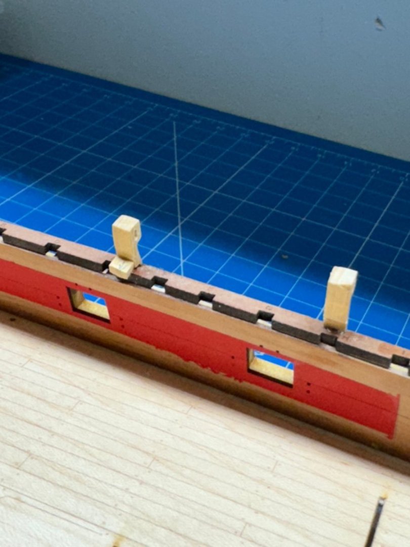
I am waiting until I get the bulwarks masked and painted before I install the new piece and proceed with the other repairs that are necessary (several inches of the QD Beam Spacing Pattern broke off as well as the "ears" on bulkheads 9 and 11).
Gluing back the QD Beam Spacing pattern piece is no problem but the ears I do not have a solution in hand. Luckily they do not come into play for a good bit yet.
-
-
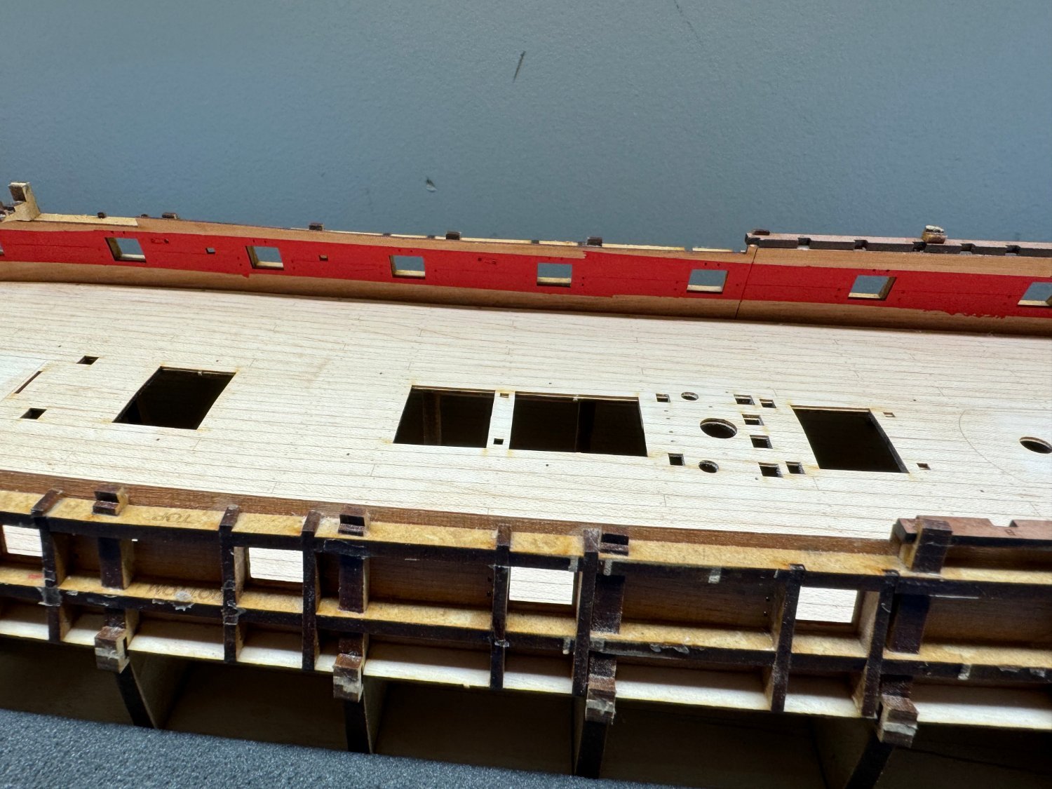
With the deck it ism getting time to paint the bulwarks.
I am generally a "Badger Paint Guy" but of late have been know to use other brands/types.
So I took a piece of carrier sheet similar to what the bulwarks came on and ran a test with the barious "reds" that I have "on the shelf".
Below from left to right: Tru-color Burlington Red; Tru-color Soo Line Red; Badger Windjammer Red; Testors 11500 Red; Vallejo 70.957 Red
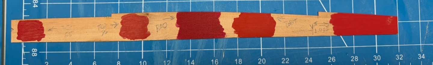
To my eye it is a tie between the Burlington Red and the Vallejo.
I am going to go with the Vallejo since it is water based and the Tru-color is not.


HMS Sphinx 1775 by cdrusn89 - Vanguard Models - 1/64
in - Kit build logs for subjects built from 1751 - 1800
Posted
If I am to use masts fabricated of Alaskan Yellow Cedar (at least the lower and topsail masts - the jury is still out on the Top Gallant masts) then I need to figure out what color they need to be. I am not sure I would like the "bright yellow (which is what AYC looks like after a coat or two of WoP) since much of the mast is covered with the cheeks and front fish which are provided in pearwood. I suppose I could fabricate them out of AYC but they have a pretty particular shape and while not impossible I do n ot want to tackle that as well as fabricating the masts.
So I assembled all the cans of stain in the "paint locker", a piece of AYC (from the same billet I cut the mast pieces from) and a section of the kit's carrier sheet that held the cheeks.
I put a sample of the stain on the AYC then, when dry a coat of WoP and well as a coat of WoP on the kit carrier sheet.
Here are the results.
As can be seen the Minwax Red Oak stain comes the closet to matching the kit's pearwood so I will stain the mast sections with that before assembling the lower masts. And the WoP makes a real difference darkening the pearwood.