HOLIDAY DONATION DRIVE - SUPPORT MSW - DO YOUR PART TO KEEP THIS GREAT FORUM GOING! (Only 68 donations so far out of 49,000 members - Can we at least get 100? C'mon guys!)
×


cdrusn89
-
Posts
1,915 -
Joined
-
Last visited
Content Type
Profiles
Forums
Gallery
Events
Everything posted by cdrusn89
-
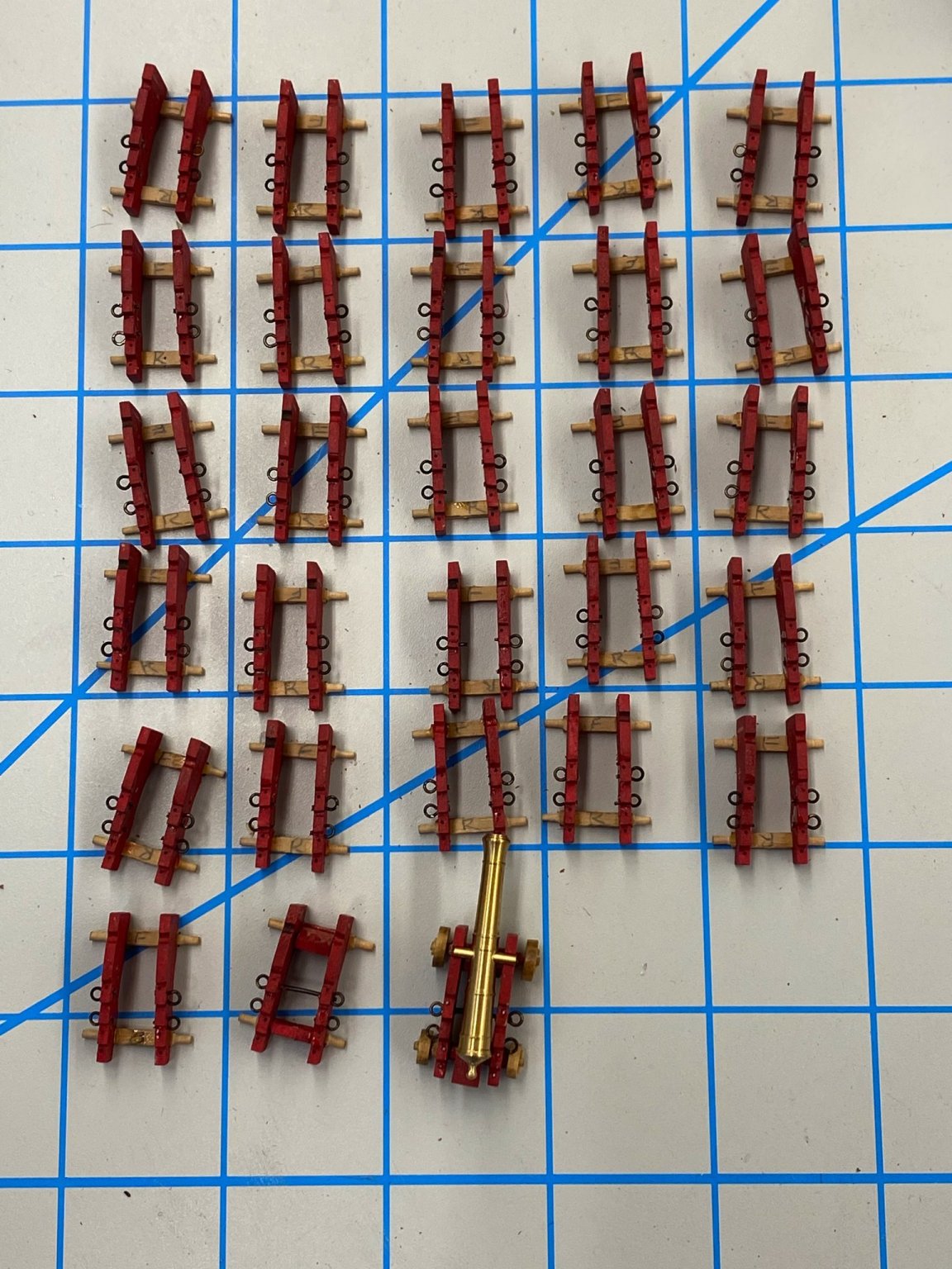
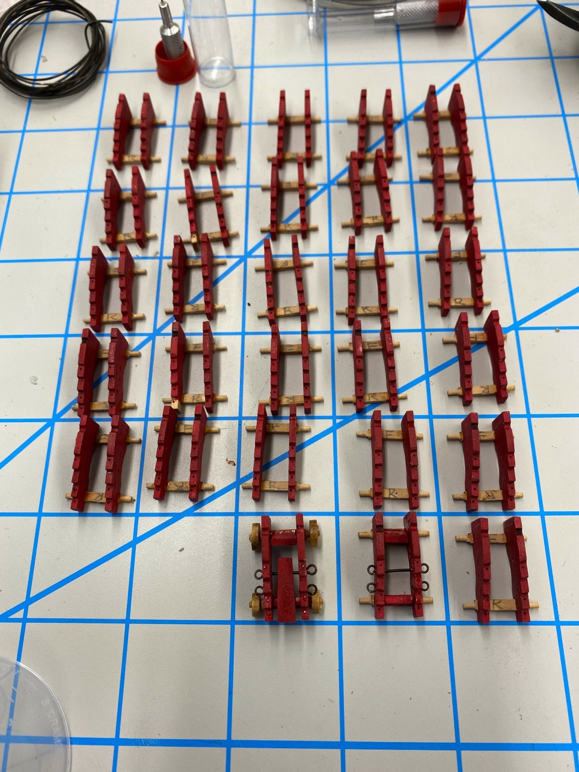
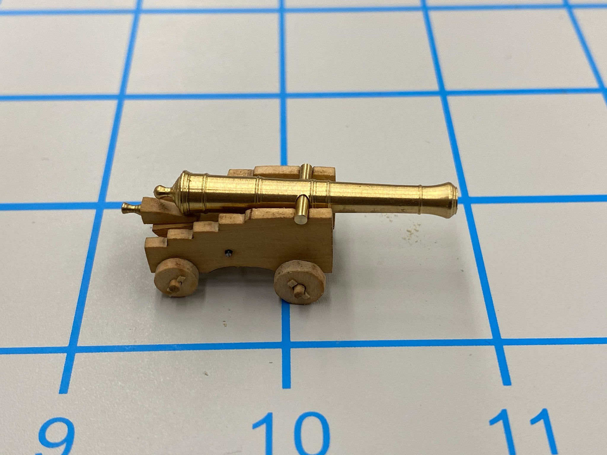
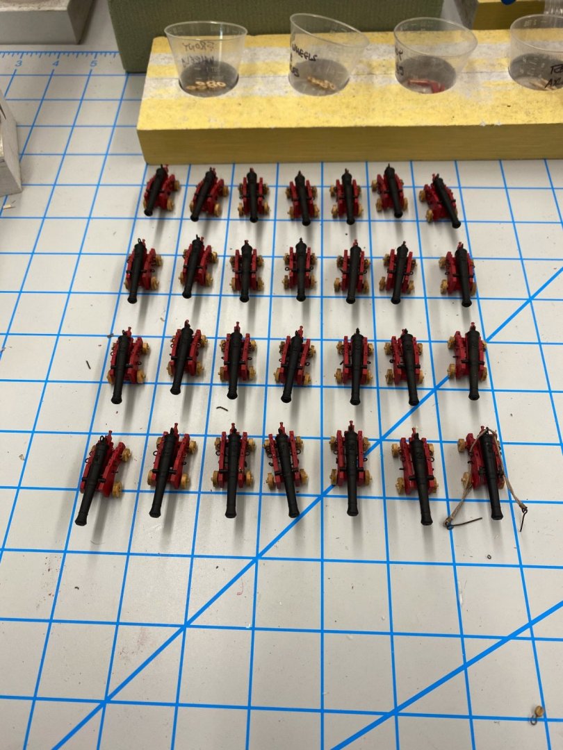
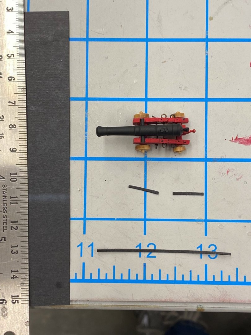
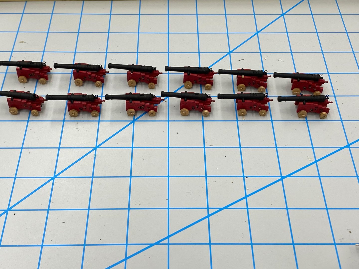
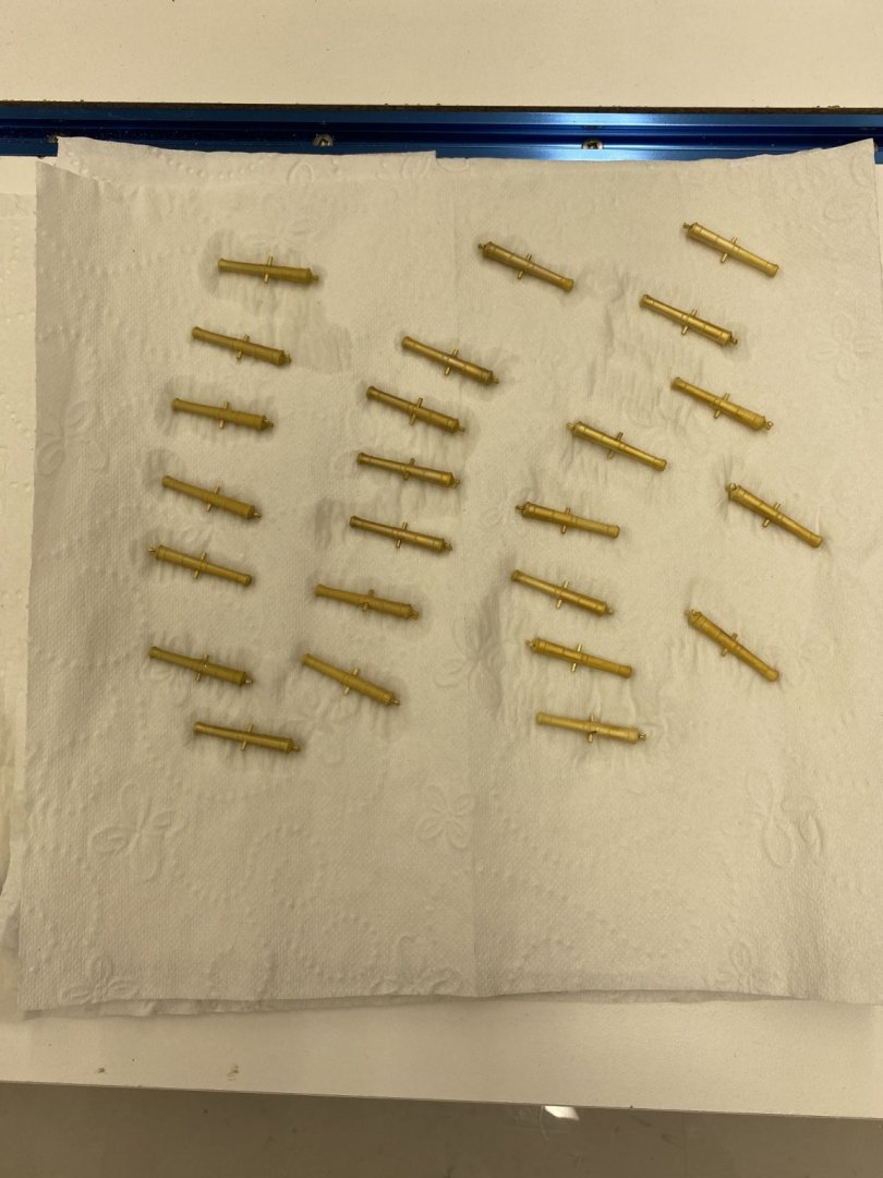
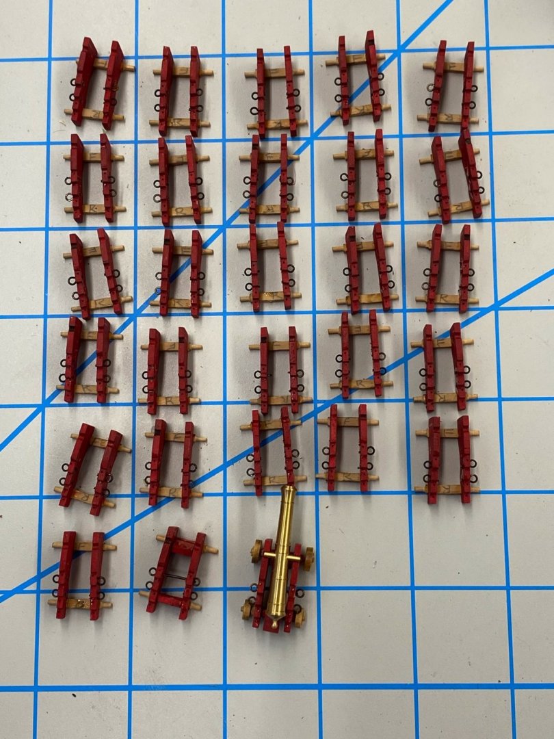
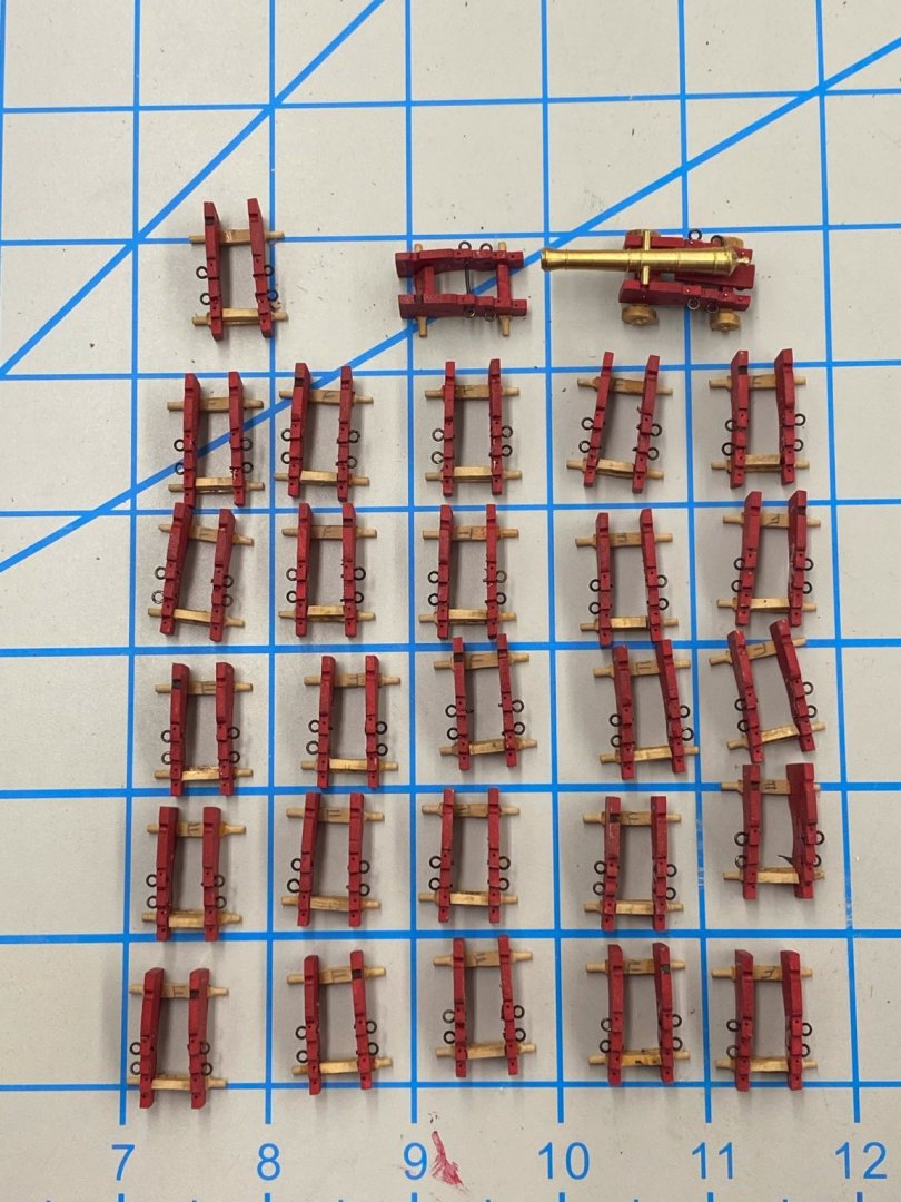
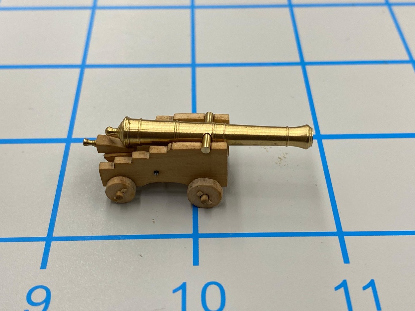
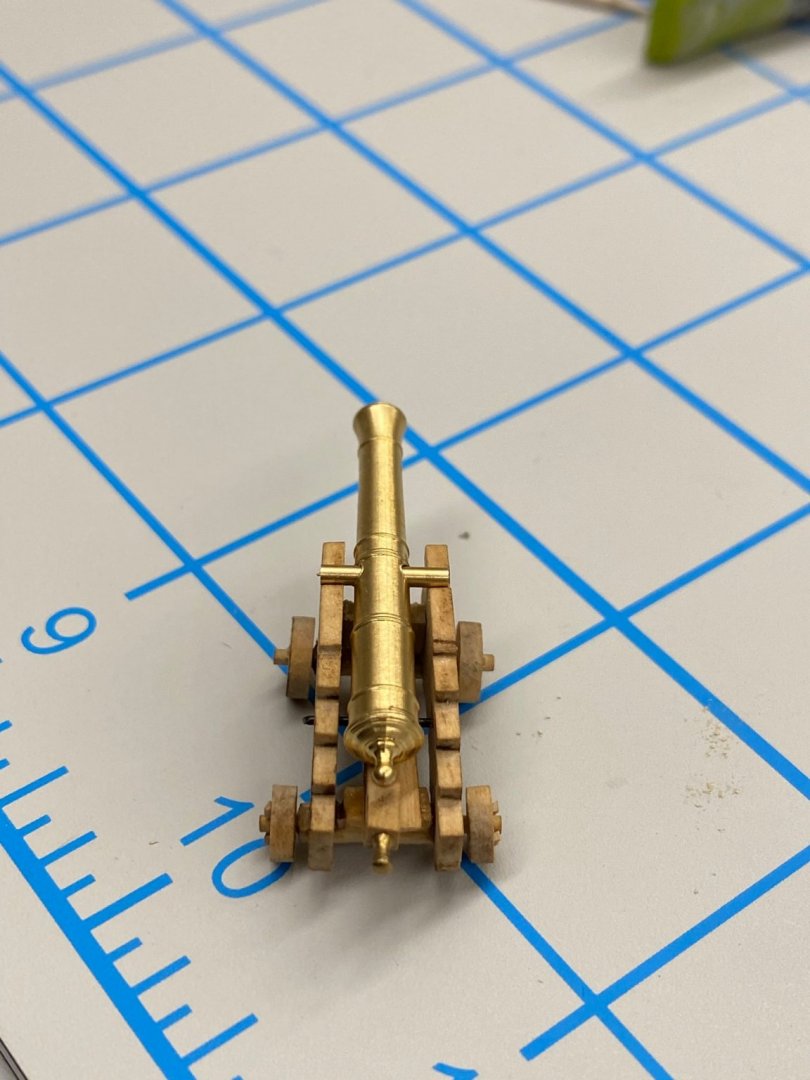
 Thanks Bossman. I finally got all the 12 pounder gun barrels painted (kept having air brush problems, think I have them resolved, at least for now) and now have them all mounted on their carriages. Glued the quions to the bed and added the rear eyebolt. Here are the 28 12 pounders mounted on their carriages Currently working getting the trunnion caps on the carriages. For the cap material I am using a black "laserboard" that is .010" thick. Probably too thick at this scale but.... I use a Xacto knife and steel ruler to cut off slices just under 1/16" wide - at least that is what I try for, not as easy (for me) as it seems it should be. I cut this into 1/2" pieces to form the caps. Using medium CA I glue a strip onto the carriage behind the trunnion trying to keep the amount of laserboard behind the trunnion consistent (at least from side to side if not exactly from gun to gun). I try and press the laserboard against the carriage/trunnion junction so it will form a curve over the trunnion. When the medium CA is dry I glue the forward section to the carriage again pushing the laserboard down against the carriage/trunnion junction as the CA dries. I try not to worry about the glue soaking through the laserboard as I am going to paint the top of the trunnion caps when I touch up the barrels and eyebolts before the breeching rigging. Using a chisel balded Xacto knife I trim the laserboard forward of the trunnion to match the length behind (at least that is my objective, not always achieved). The last step is to drill a #77 hole on each side of each cap and insert a short length of 28 ga wire to simulate the bolt head that holds the trunnion cap down - similar to the other simulated bolts in the top and sides of the carriage. Thus the need for black paint on the trunnion caps. I will have all these finished this weekend (I hope) and then will start work on the 6 pounders. I pal on building all 8 even though it is likely at only four will be included with the model. I will cross that bridge a little further down the road (okay a lot further) and if I do not assemble the extra four now I doubt I would be inclined to do it then. At least now I am in the gun building "rhythm".
- 370 replies
-
- 5
-

-
- Model Shipways
- Confederacy
- (and 1 more)
-
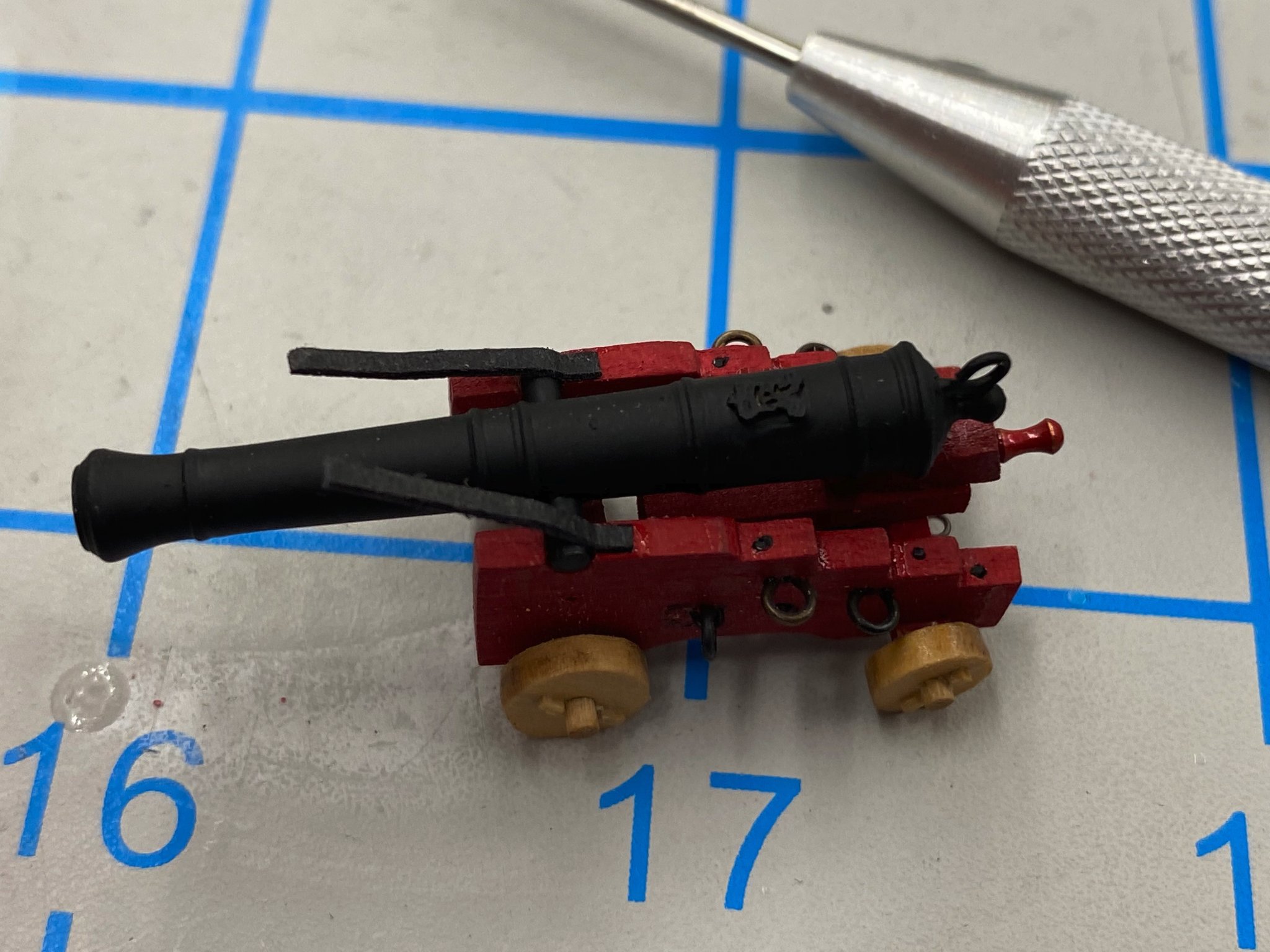
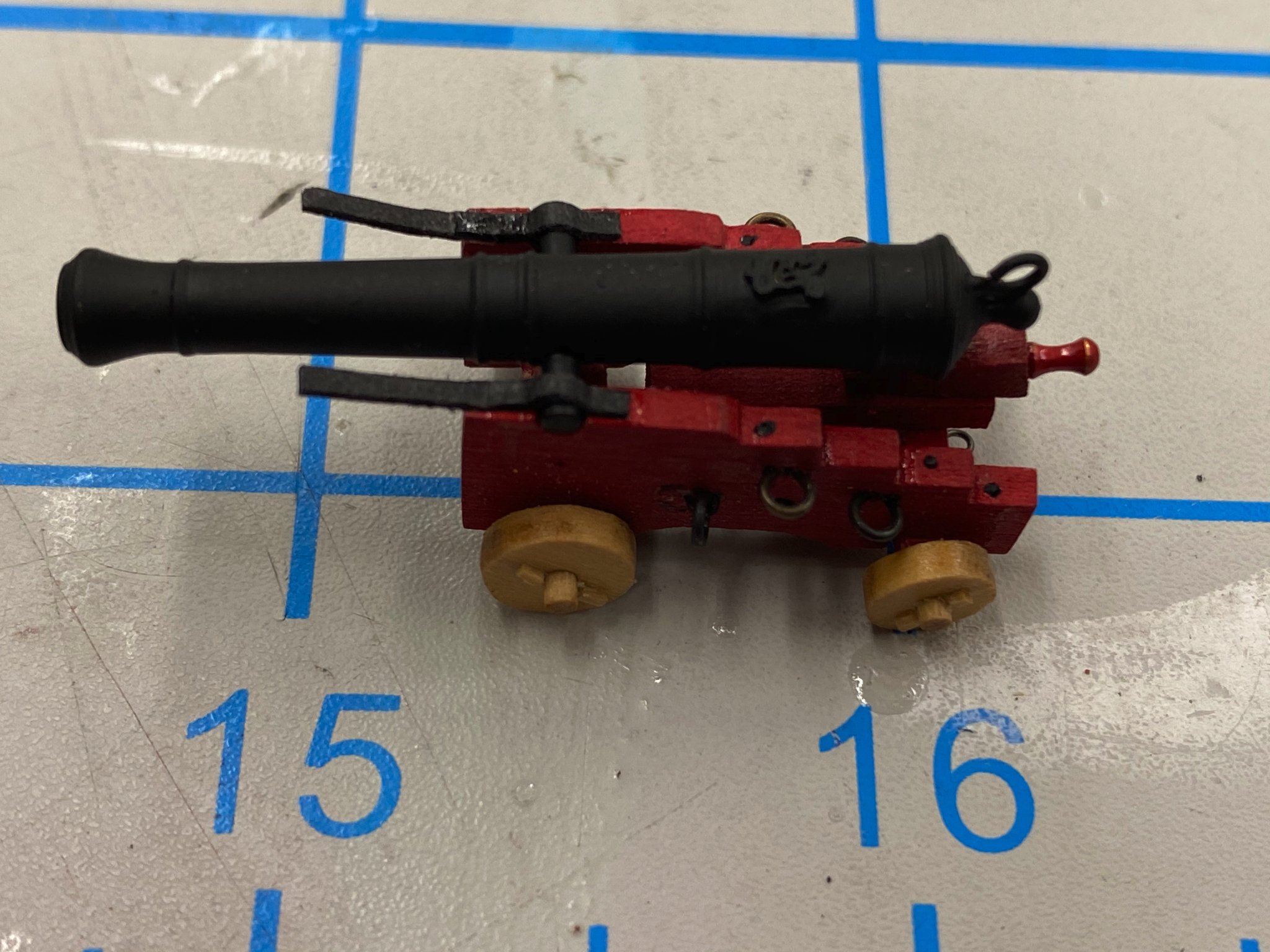
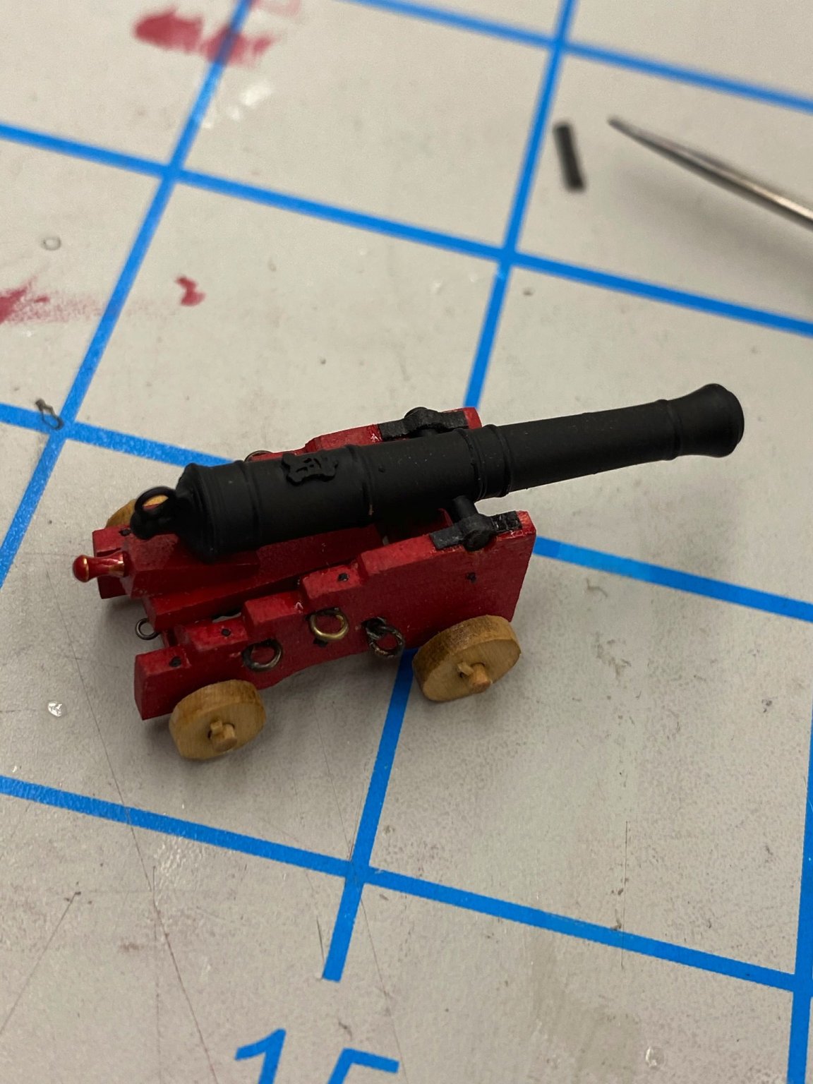
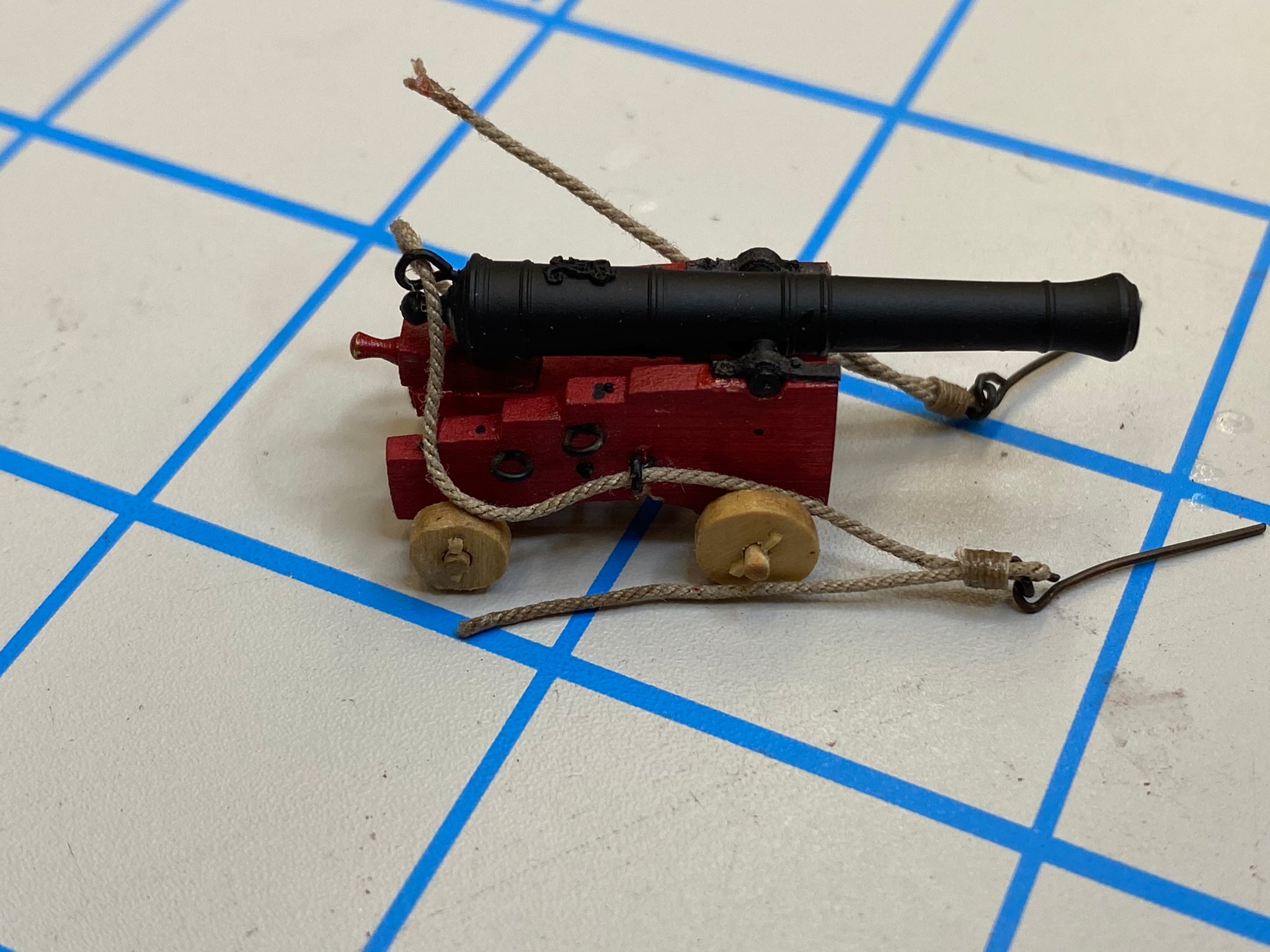
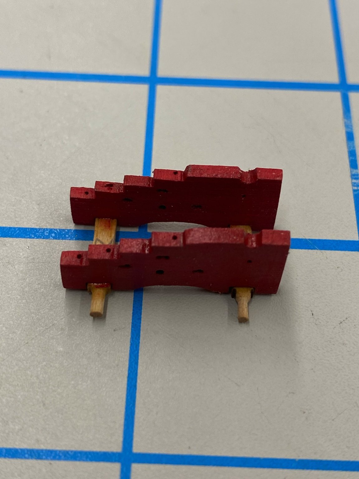
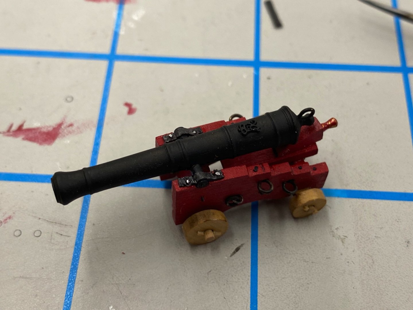
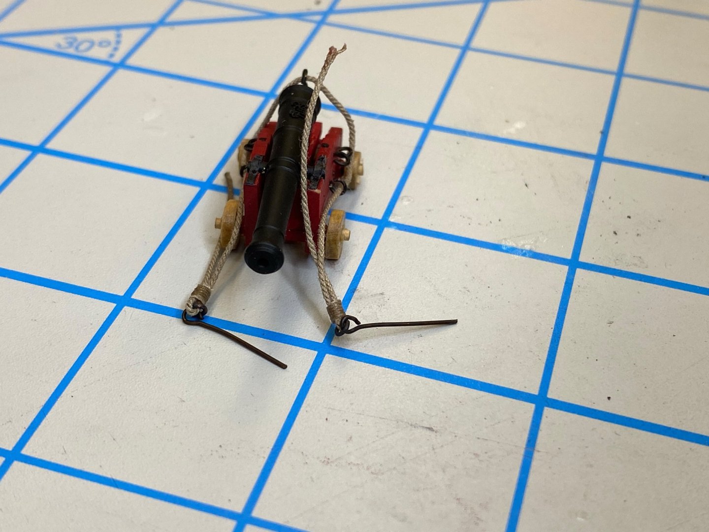
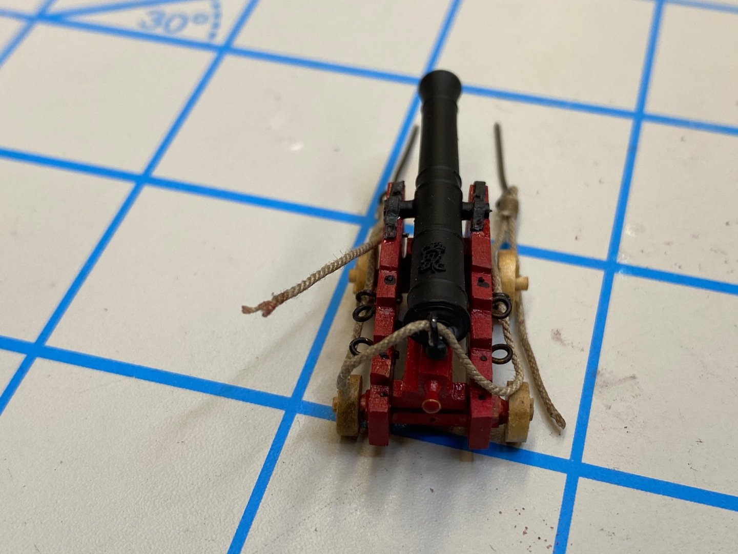
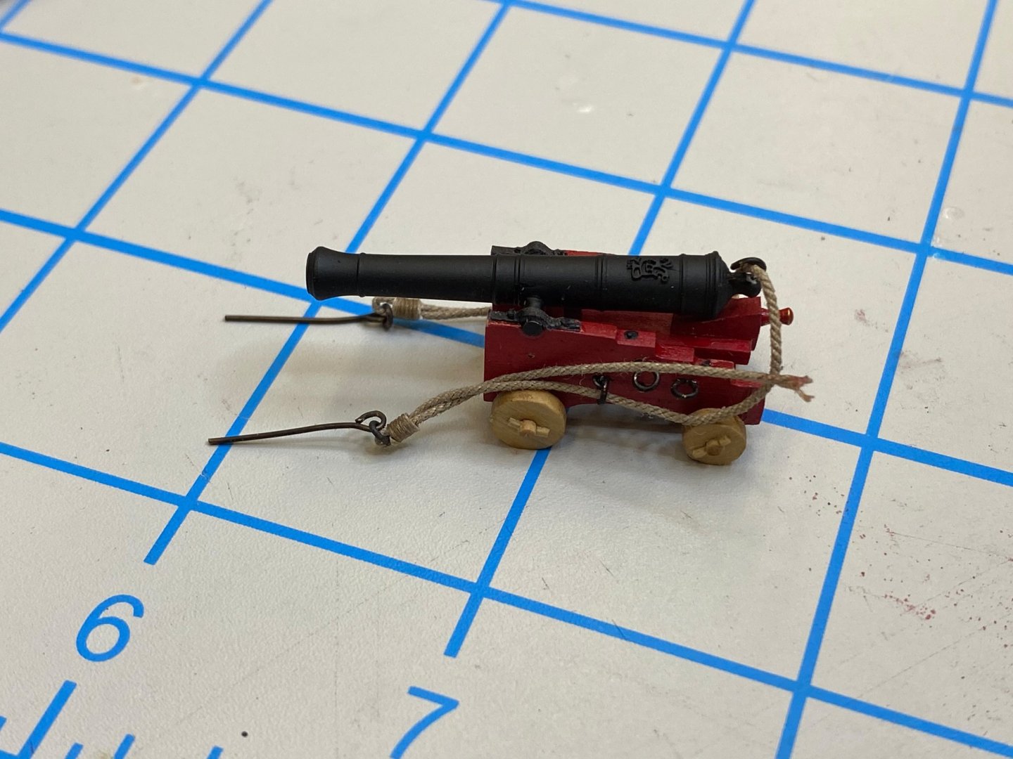
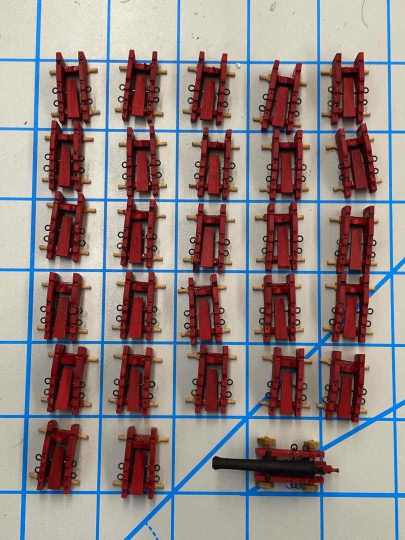
Continuing the saga of building the Confederacy's armament I added the eyebolt and split rings for the breeching tackle to the sides of the carriages. The instructions say not to add these until the breeching tackle as been assembled but I choose to do it now. I used the 3/32" split rings (although given the size of the eyebolts I used for the outhaul tackle I probably could have used 1/8") and 32 ga annealed wire to make an "eyebolt" around the split ring. It was important (don't ask me how I know) to grip the split ring with the "split" inside the grip of the pliers used to hold the split ring while wrapping the 32 ga wire around the split ring. It takes longer than it seems it should since you only need a half dozen or so "wraps" to get a shaft long enough to fit through the carriage side and be secured. i used medium CA to create a bond around the shaft of the eyebolt and the carriage inside to hold the split ring. On several I had to pry the split ring off the carriage side since some of the CA had leaked through the hole and bonded the split ring to the carriage side. After getting the breech tackle taken care of the next step is to glue the barrel and quion into place. No big deal here except I filed out the half circle that the trunnion sits in on the carriage to help grip the trunnion. Here are twelve of the carriages with the barrels mounted. I decided to take one of these and add the trunnion caps and the breeching tackle. For the trunnion caps I used black laserboard cut to just under 1/16" width. I used medium CA to glue first one side, then the other using an awl to keep the laserboard in contact with the carriage and trunnion so it would form a nice semicircle around the trunnion. I used the 28 ga annealed wire to simulate the bolt heads holding the trunnion cap to the carriage sides. The instructions call for .028 tan rigging line for the breeching tackle. I am a big fan of the Syren rigging line and the closest I can come to .028 in that material is .025 so I used that (and will use .018 instead of .021 for the 6-pounders). I have been using the "zip tie" method of securing lines (see Wooden Ship Models for Dummies") so am able to rig the breeching line while allowing for each end to be adjusted to its final length after the carriage/gun assembly is mounted onboard. Here are four shots of a single carriage with the breeching tackle ready for mounting onboard the ship. When mounted onboard and final adjustments to length are complete I will attempt to get the breeching line to lie in a more "sailor-like" manner and am not ruling out glue as a method for achieving this.

- 370 replies
-
- 4
-
-
- Model Shipways
- Confederacy
- (and 1 more)
-
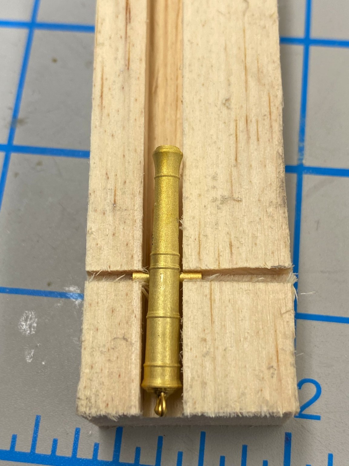
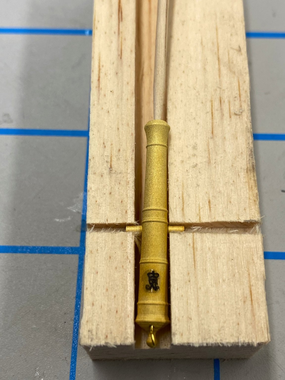
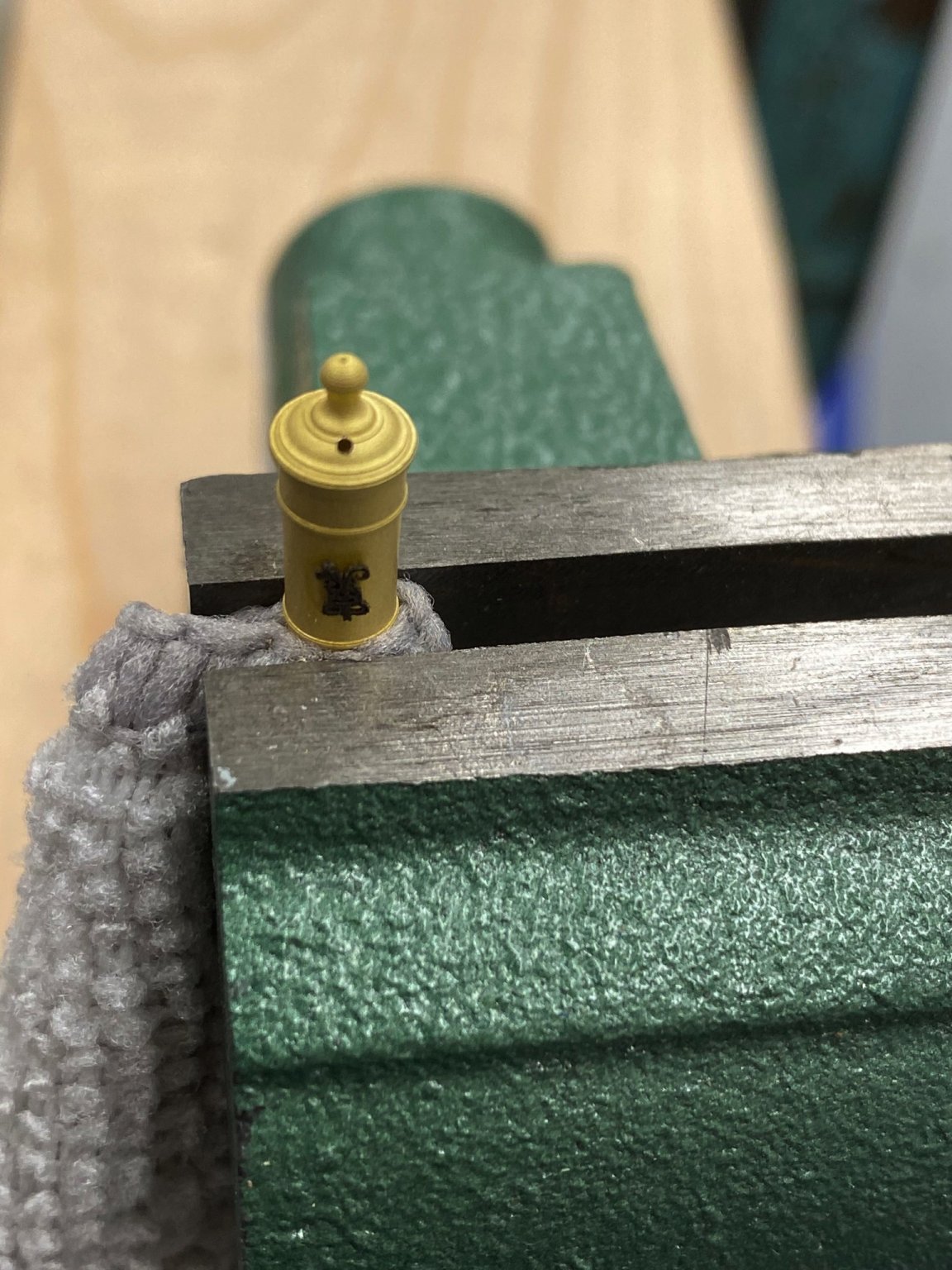
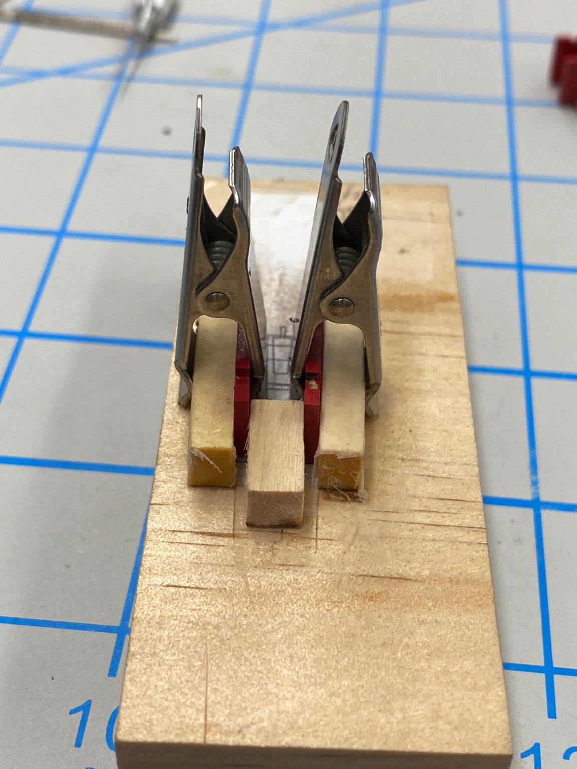
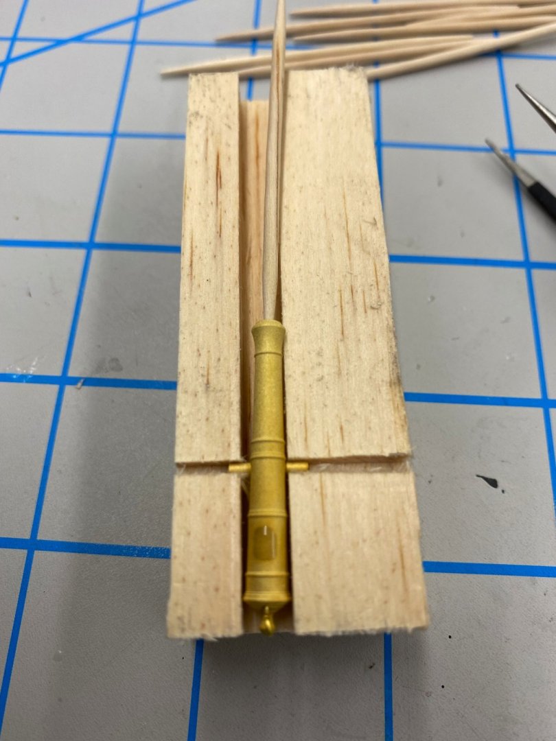
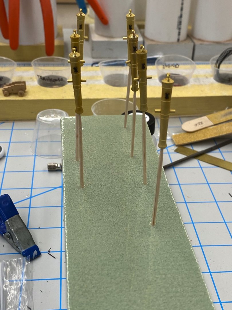
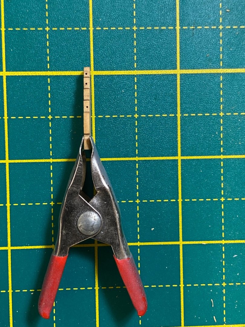
With the cannon chemically cleaned now comes the application of the "Royal Monogram". Since there are 24 of these yet to be done, I decided that I needed a jig to hold the barrels so they didn't move around while the monogram is glued on. I cut a groove in a scrap to hold the barrel and then a slot for the trunnion. Here is the jig with a barrel inserted. I used a toothpick in the barrel so I could stick them into a floral block for painting. Here is a barrel with medium CA applied to the area where the monogram will be applied. And here it is with the monogram applied. And here is the floral block with several barrels inserted.


- 370 replies
-
- 4
-
-
- Model Shipways
- Confederacy
- (and 1 more)
-
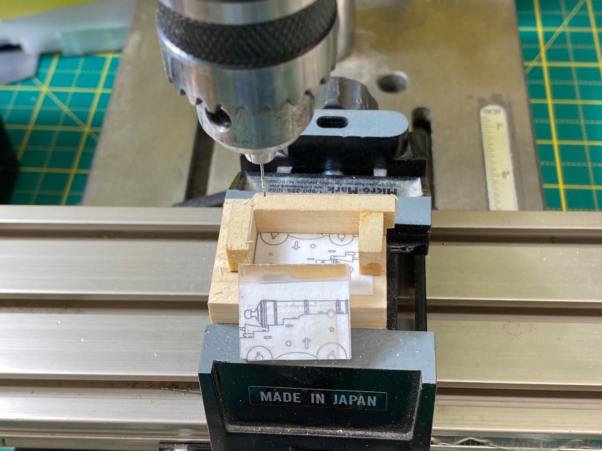
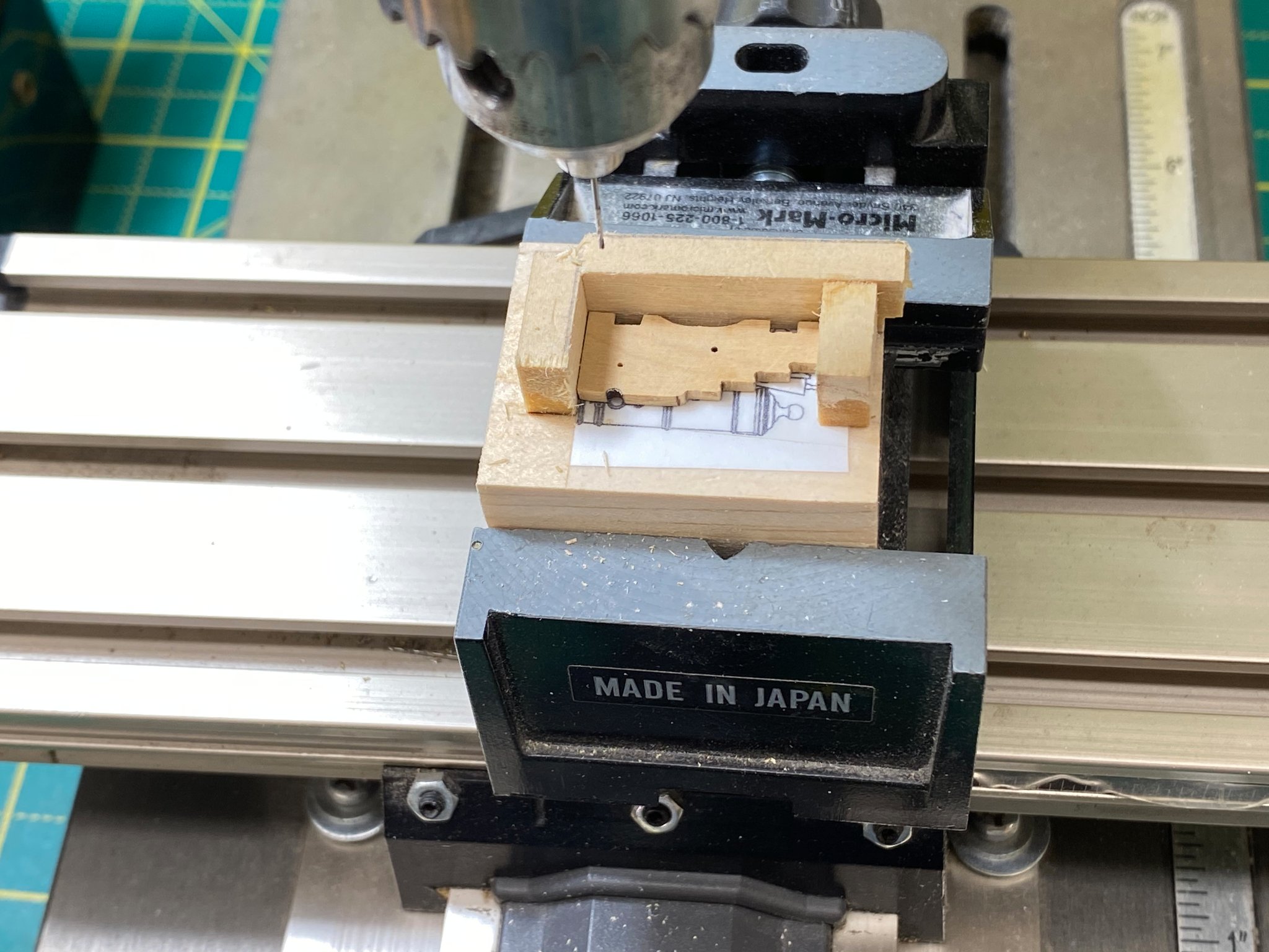
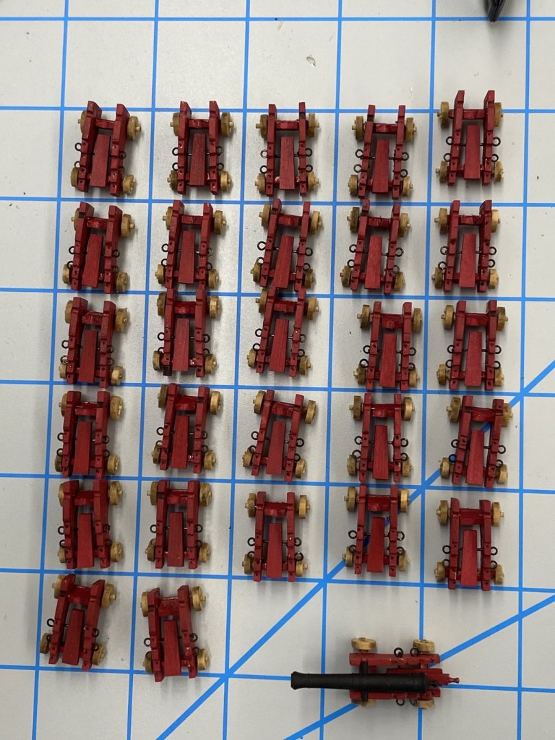
With the stool bed added the last item before the cannon are the wheels. I had kept them separated throughout the assembly process so it was and easy task to get the correct wheel on the correct axle. Here is the rogues gallery of the 28 carriages for the 12 pounder cannon. I decided to get the remaining 24 cannon barrels for the 12 pounders ready now. I have not decided exactly how I will mount the barrels (tape, card stock, laserboard, brass) so this will give me some more time to figure that out. I could also assemble the carriages for the six pounders and configure those too if I need more time. The set of barrels that I used to establish my process are in good enough shape to go onboard so I will keep my spare set "in reserve" for now. Anyway, here is what comes from Syren - each package is four cannon. Generally speaking the trunnion pin slides easily into the hole in the barrel. I think there were two or three where I had to hammer the pin in. On the rest I used thin CA to glue the pin into the barrel. IMHO it is important to get the pin in the barrel as the first step as this makes it much easier (at least for me) to make sure I knew which side was "up" and when the barrel was level. The next task is to drill the hole for the eyebolt at the rear for the breeching rope to pass through. I had a hard time drilling a #74 hole (the smallest that will accommodate the eyebolts I plan to use) directly so I started with a #76 and then enlarged it to #74. The real trick was figuring out how to mount the barrel so it would not move while drilling. (This is where I used my variable speed drill press and x-y table to get the drill where I wanted it and a foot switch so I had both hands free while drilling. After the hole is drilled I used medium CA to glue in the eyebolt after cutting the shaft short enough to the eyebolt is very close to the barrel. Next step is to chemically clean the barrels (and as a bonus the eyebolts too). Luckily the chemical cleaner does not appear to attack the CA so the eyebolts and pins stay in place. Here are the 24 barrels after cleaning. Next applying the monograms and then the paint booth.


- 370 replies
-
- 6
-
-
- Model Shipways
- Confederacy
- (and 1 more)
-
After the brief sojourn into cannon barrels above I returned to the carriages and added the 22ga wire that supports the forward end of the stool bed and the 28ga wires that simulate the transom attachment and then painted the cut ends of the annealed wire flat black. I found that just touching the end of a sharpened awl to the paint that sticks to the bottle cap captured just enough paint to do the two wires on one side. Only 57 more to do. Here is an example side with the wires painted. With that done next was to add the stool bed. I used medium CA on the rear axle bolster and the 22ga wire to secure the stool bed. I tried to get them all to end just inside the end of the carriage sides (per drawings) so that the quoin will not overly depress the barrel. Having the barrel slightly higher in the carriage (trunnion is just below the barrel centerline) helps something I may not have discovered when I built Niagara. Anyway here is the rouges gallery of the 27 carriages and the one example, now with a black gun barrel.
- 370 replies
-
- 3
-
-
- Model Shipways
- Confederacy
- (and 1 more)
-
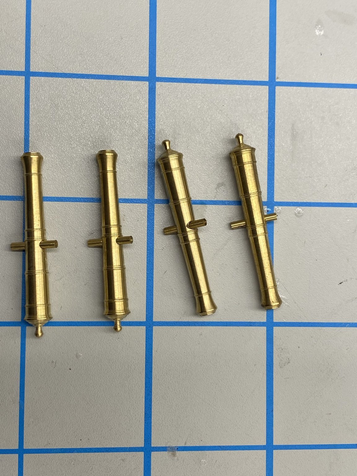
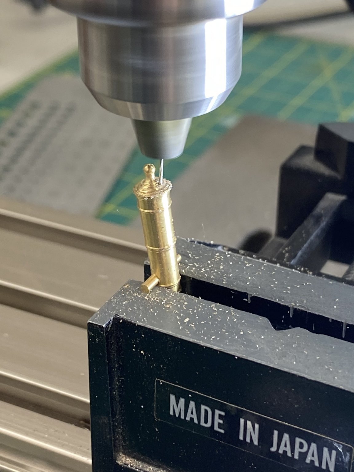
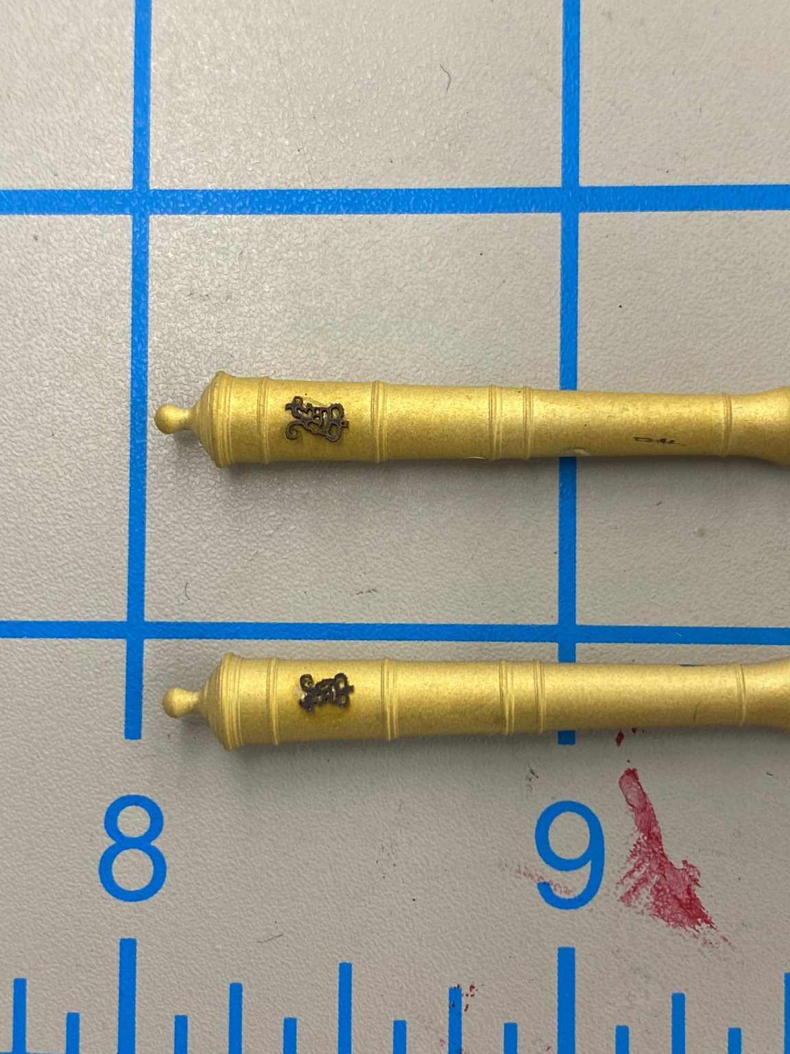
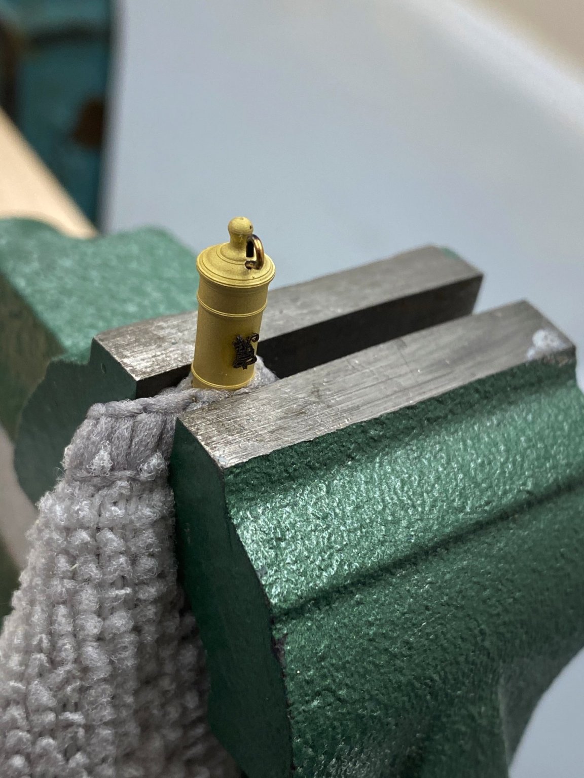
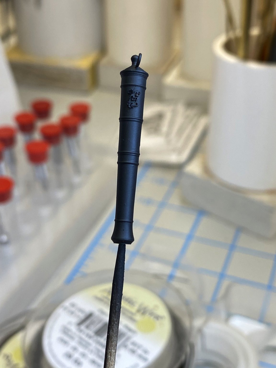
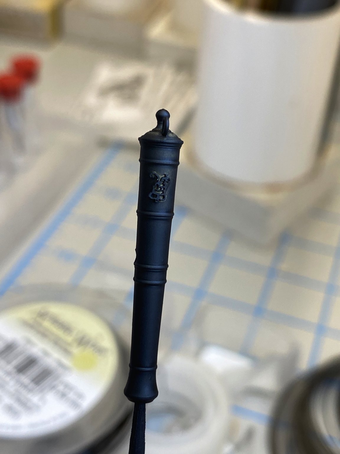
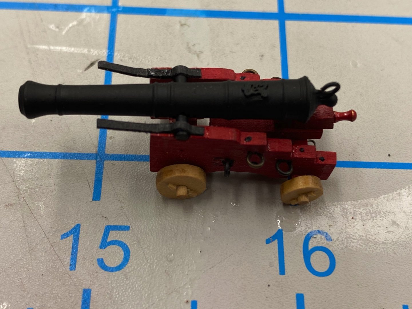
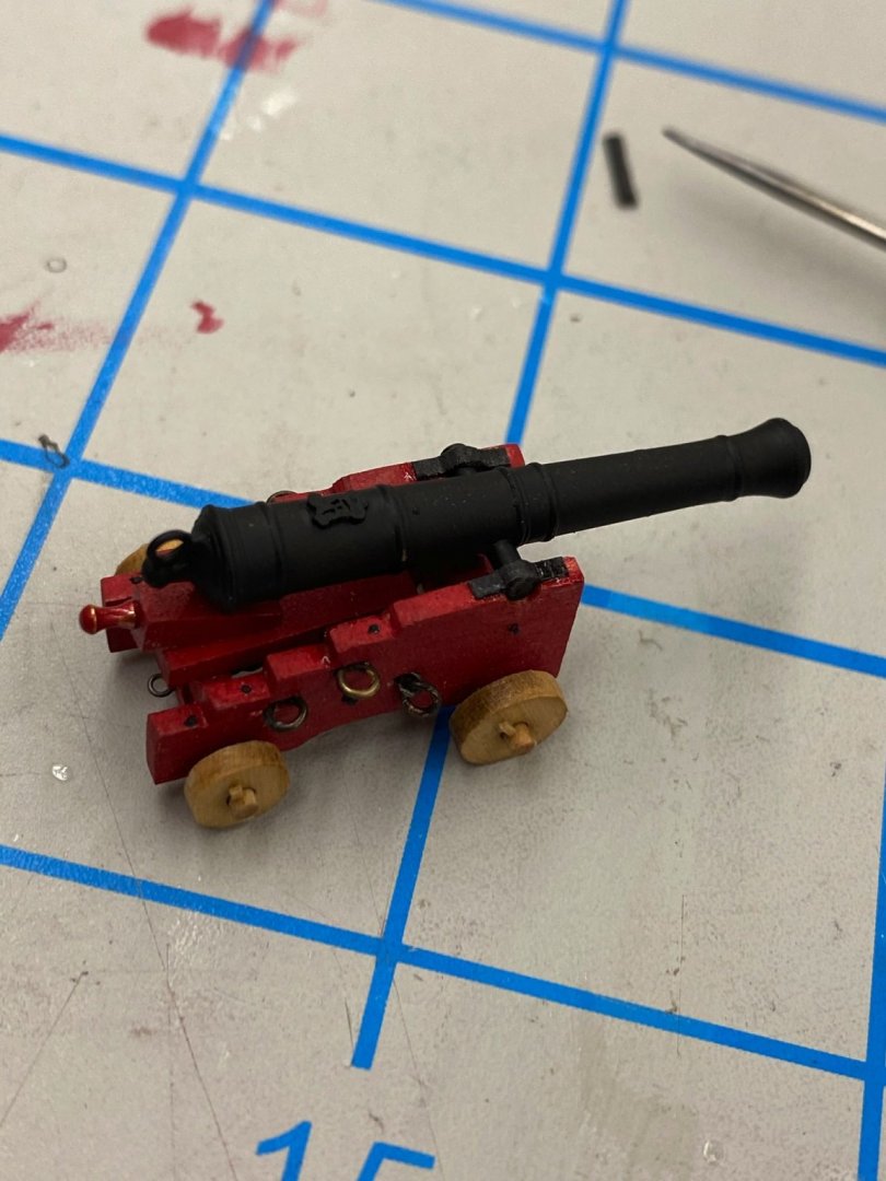
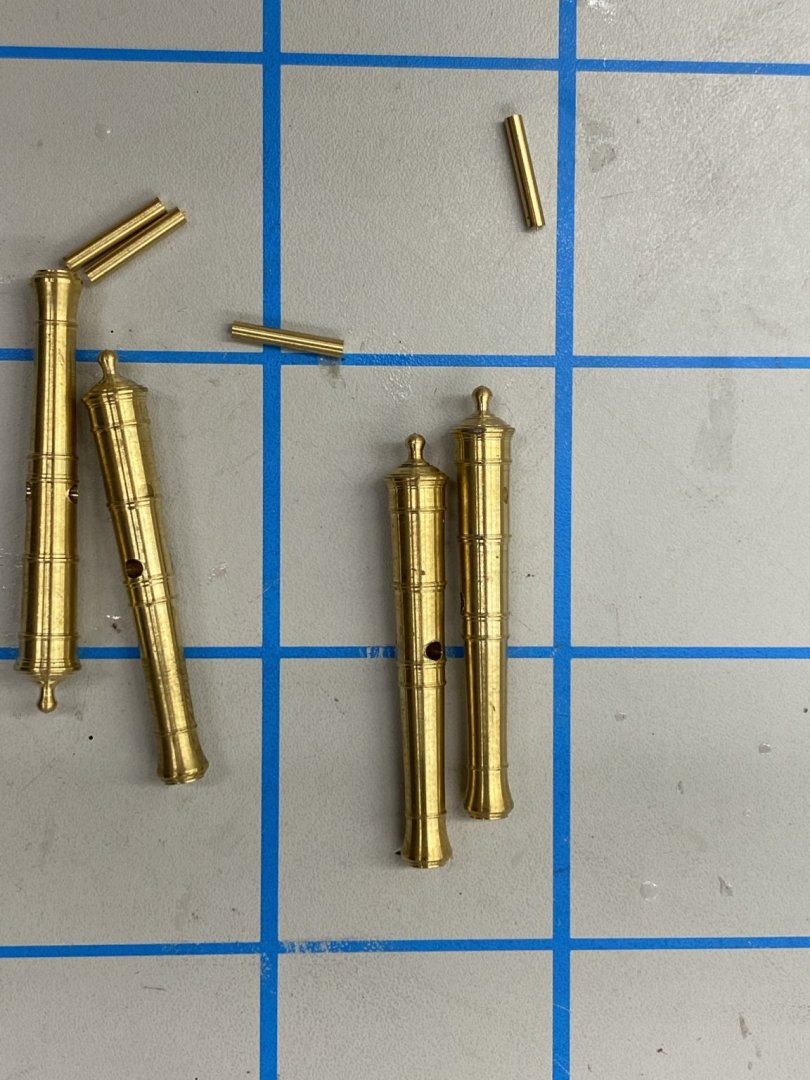
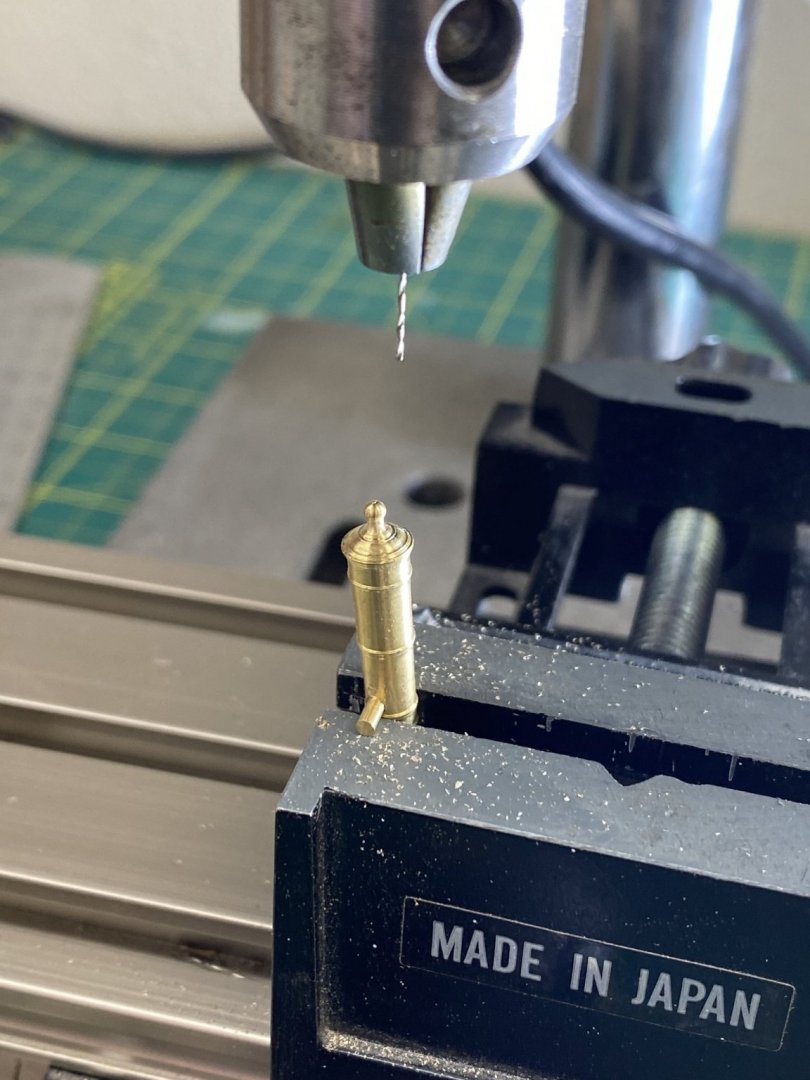
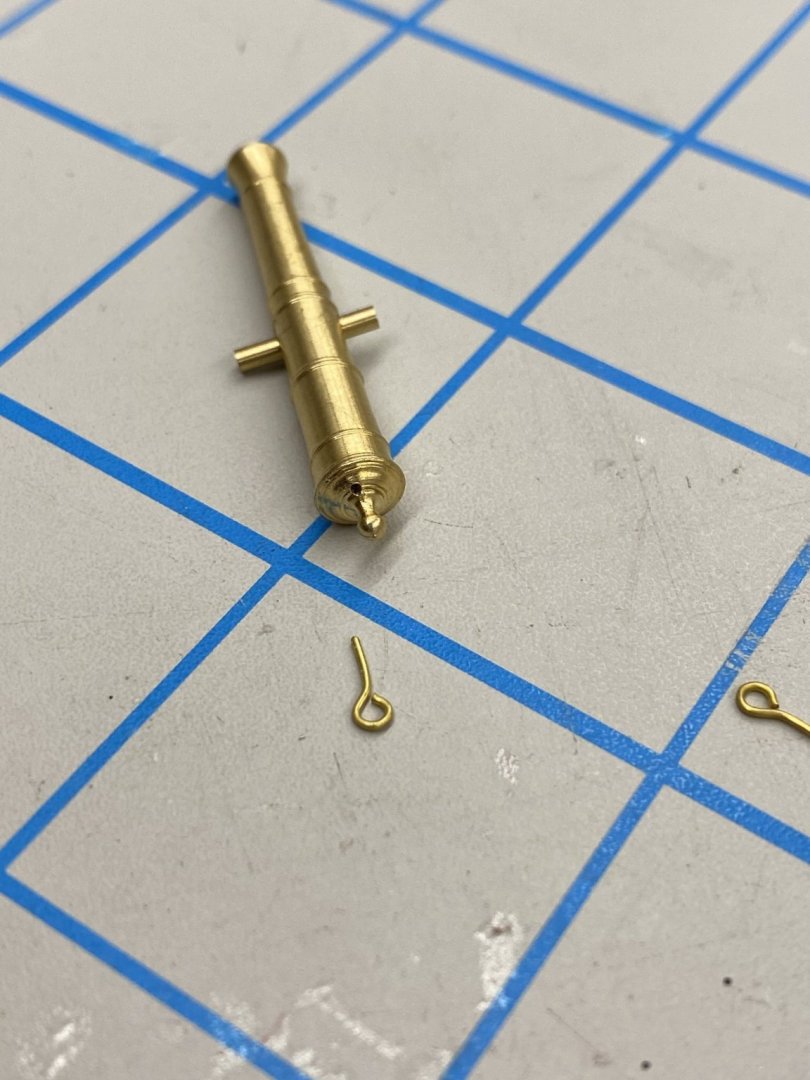
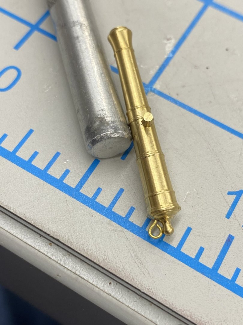
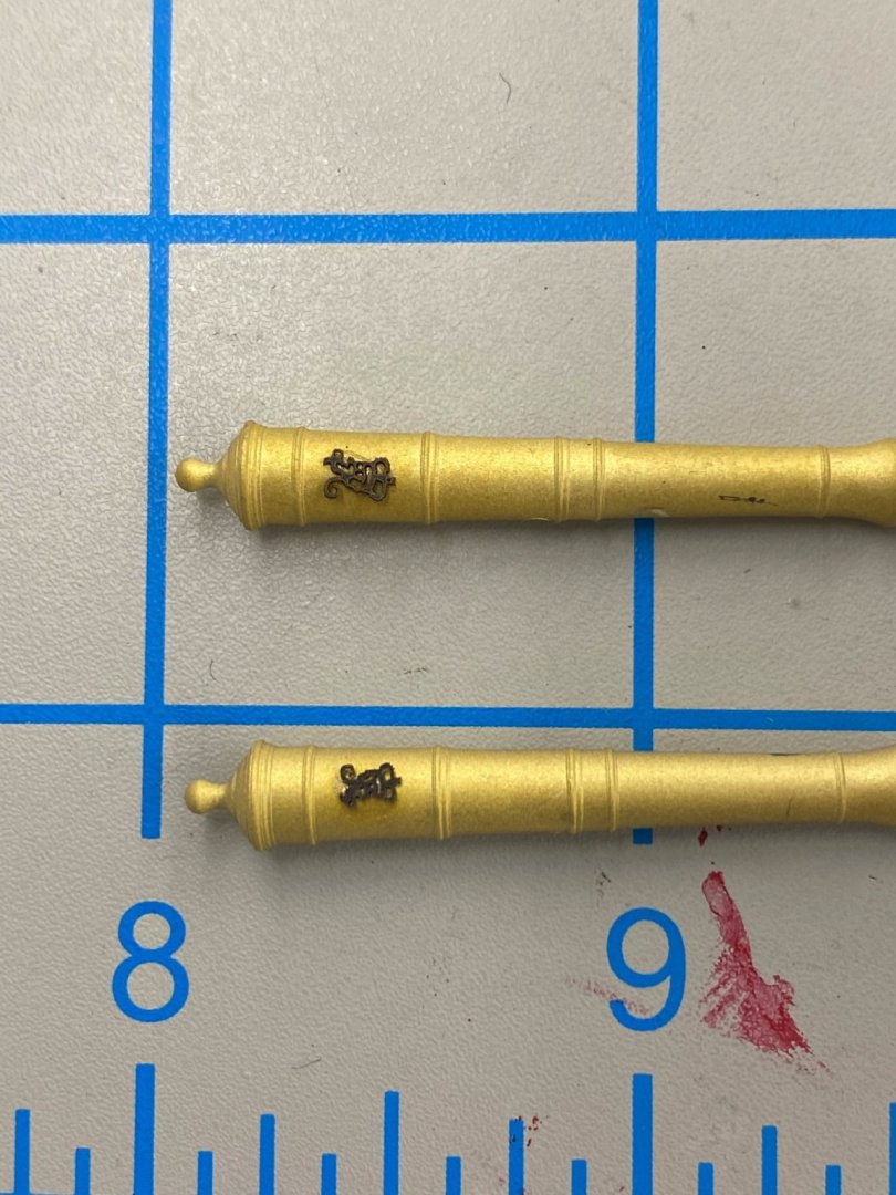
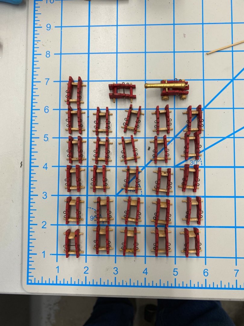
While fiddling around with the gun carriages I decided to make a foray into the cannon. I have the 1 29/64" Syren brass guns that are for these carriages and was trying to decide whether to paint or chemically blacken them. I have looked at various blogs, forums and the NRG journal (which had a shop tip on the subject last quarter or the one before) and none of these techniques seem to yield a really black finish that does not rub off to some degree when handled - which will of course be necessary to some degree just getting them on the carriages to say nothing of rigging them. So I think I am going to paint them (Badger Black (1943) - 16-454) which is a flat finish. I bought a spare set of four barrels so I have some latitude to experiment. I took two of them and cleaned them using JAX Instant copper and brass cleaner. I put them in a small container, covered them in cleaner and then used the ultrasonic cleaner to make sure I got them good and clean. They are not the shiny brass that I thought I was going to get but maybe that is okay. I really want some texture to the finish to give the paint something to which to stick. Too smooth is not good. We will see how this goes. The next thing I figured out is that the barrels have a top and bottom. The hole for the trunion is not located in the center of the barrel. Close examination of the drawing shows that the "top" is the side with the larger part of the barrel above the hole. This will be important as the next two steps make additions to the barrel on the "top" side. The next project was to apply the monograms (also from Syren). These are located on the top of the barrel just above what would be the breech if it were not a muzzle loader. They are supplied in three sizes so I tried the two larger. Here are the cleaned barrels with the two monograms applied (thin CA). I think the smaller and may try the smallest one on the next "experiment". I also need to look more carefully at which side of the monogram is "up". Have to check the Syren site to see how they should go. The next item is an eyebolt for the breeching rope to pass through. This requires a hole drilled into the top center of the barrel between the knob and the top. I used my power screwdriver and a #76 bit to drill this hole but will use the drill press for the next one as the slow speed screwdriver takes forever and a day to drill even as shallow hole in the brass. Also, I used a center punch to mark where the hole should go to keep the drill bit from wandering. Here is the barrel showing the hole and with the eyebolt installed (thin CA again). Now for the paint. I used my Badger Talon airbrush and thinned down the Badger 16-454 about 1:1 from what came in the bottle. I will have to touch-up the barrel where the toothpick was used to hold it . I am starting to wonder if the monograms are worth the effort. Especially since these guns are not going to be all that easy to see as they are under the forecastle, quarterdeck or boat storage. I will probably go ahead with them, it only takes a minute or two and I already have the monograms. Will definitely use the smallest ones on the 6 pounders that go on the upper decks. It also appears that I need to carefully spray the monogram as the second one below appears to not have been covered completely. Now back to the carriages.


- 370 replies
-
- 3
-
-
- Model Shipways
- Confederacy
- (and 1 more)
-
Thunder, Thanks but I think, based on the extensive list of models you have built that your experience base is as extensive as mine. I have tried to avoid square rigged vessels since I did Niagara. All those yards and rigging is still intimidating me.
-
Greg and Seahawk, Thanks for the info I will give the primers a try.
-
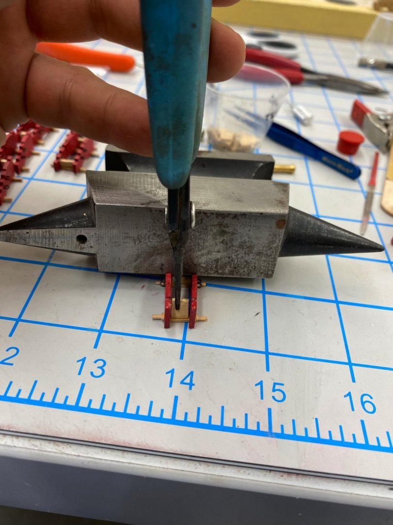
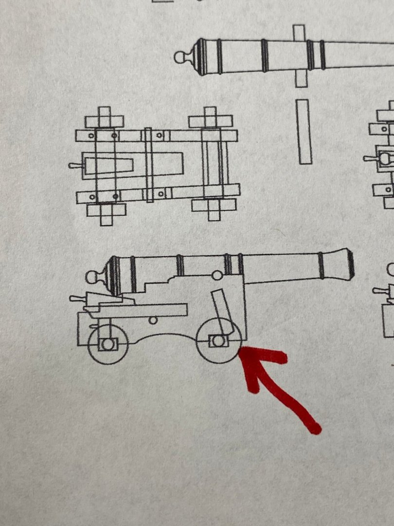
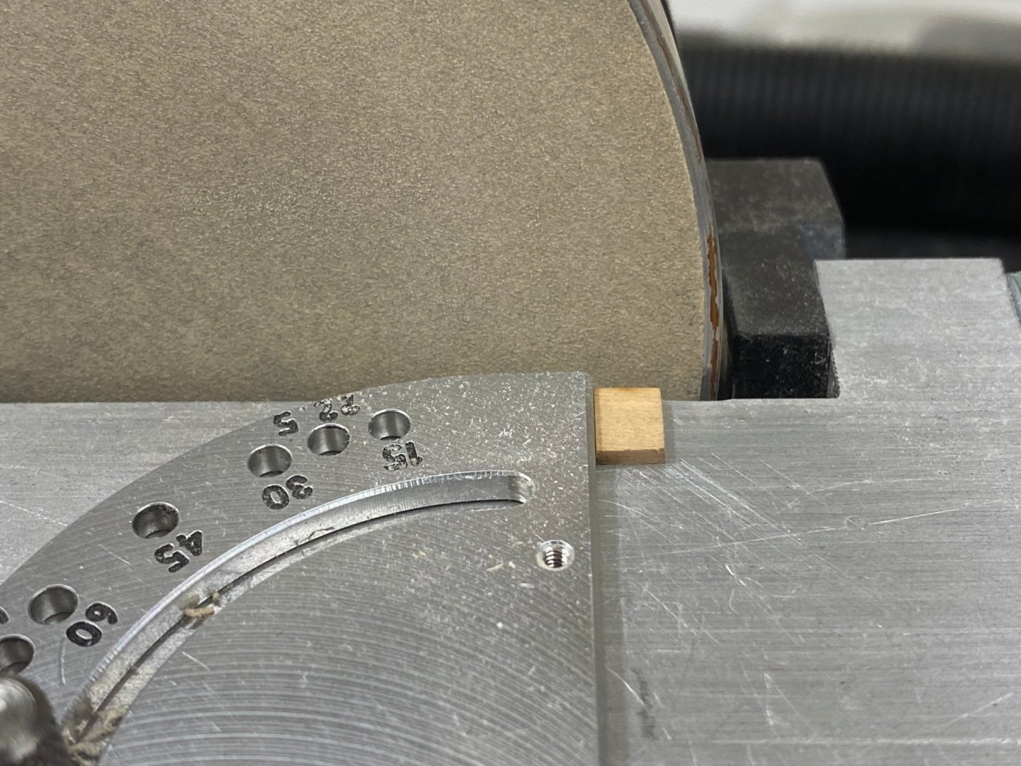
The next step (at least as I see it) is to install the transom above the front axle. As shown in the drawing below (this is the drawing from the Syren web site which is for the carriage kits sold there but this is essentially identical to the drawing included on Sheet Four the Confederacy plans - just easier to photograph) the transom should go just forward of the front axle and is tiled toward the rear of the carriage by about 15 degrees. I took the cowards way out and decided to mount the transom on top of the front axle instead of in front of it. To get the rear tilt I used the disk sander to put a 15 degree slope on one end of the transom. I then used thin CA to glue it to the front axle. I used the anvil to hold the carriage assembly steady while applying the glue. Here is the rouges gallery now with the transom installed. With the transom installed it is time to paint the carriages again - trying to leave a clear spot on top of the rear bolster to which to glue the stool bed. Here are the 26 carriages (upside down) with the paint drying. I decided to paint the bottom of the axles too - just for completeness - it is not likely anyone will ever see them once they are installed.
- 370 replies
-
- 5
-
-
- Model Shipways
- Confederacy
- (and 1 more)
-
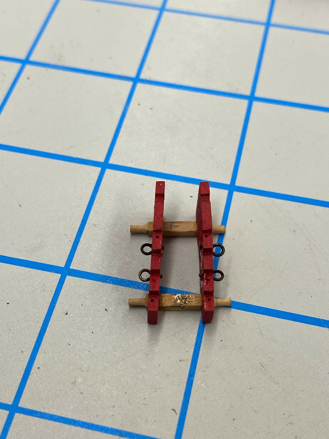
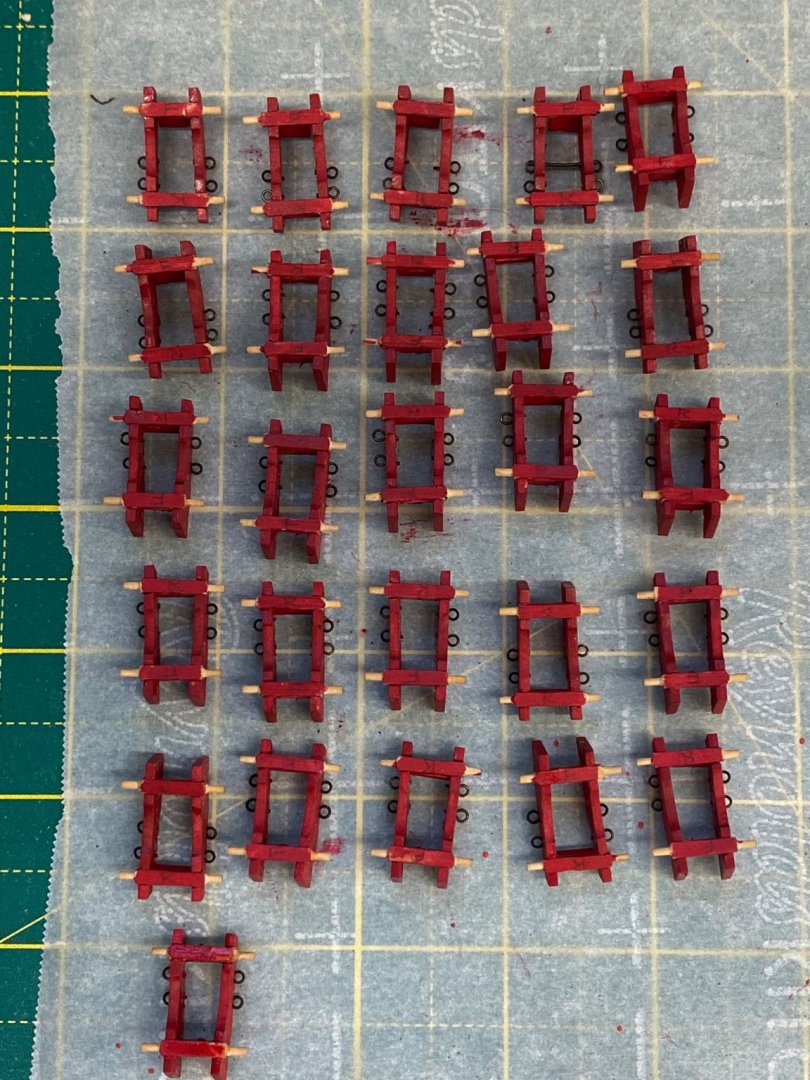
Two additional items added to all 26 (I haven't caught up with the two prototypes yet) gun carriages. Two eyebolts added to each side of each carriage. I used 3/32" brass eyebolts that have been chemically blackened. I tried to handle them with my hands as little as possible to keep them as black as possible. I did one side at a time put a drop of medium CA on the inside of the carriage. When the glue was dry I clipped off the excess shank inside the carriage. Here is the "rogues gallery" of the 28 carriages with eyebolts installed. Here is one carriage with the eyebolts installed. With the eyebolts installed the next step is the rear axle bolster. Looking at the laser cut part and the drawing shows that the laser cut part is about 1/16" too long to fit between the carriages over the rear axle. So each needs to be "custom fit" to the carriages. Somewhat of a pain but I suspect the extra material was provided on purpose to allow for some variation in the spacing of the carriage sides at the rear. Here are the carriages with the rear bolster installed. Next up is the transom at the front of the carriage.

- 370 replies
-
- 2
-
-
- Model Shipways
- Confederacy
- (and 1 more)
-
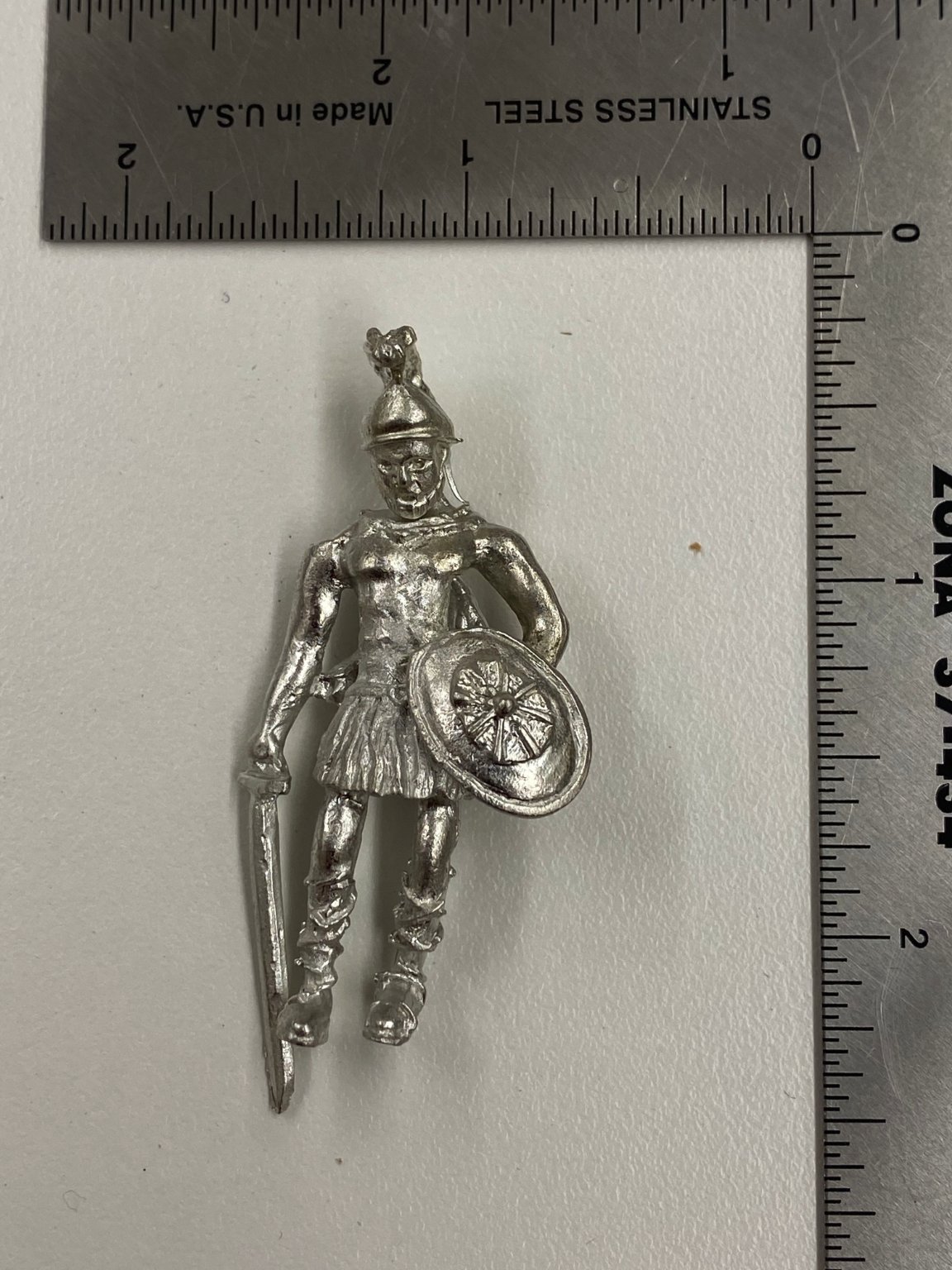
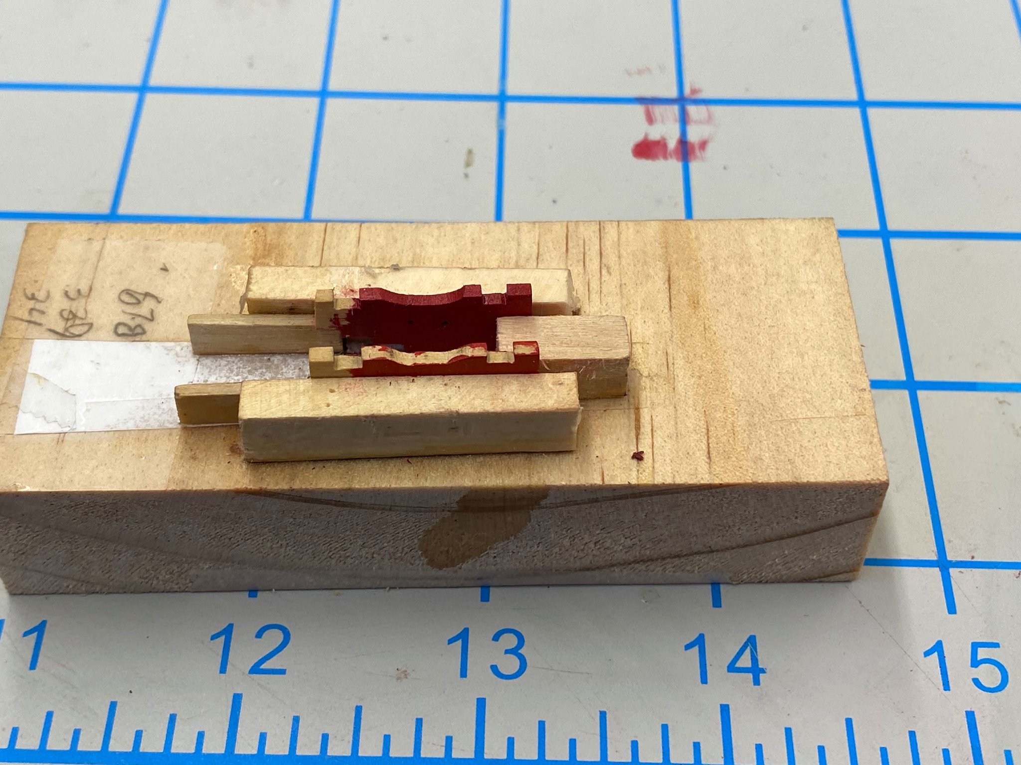
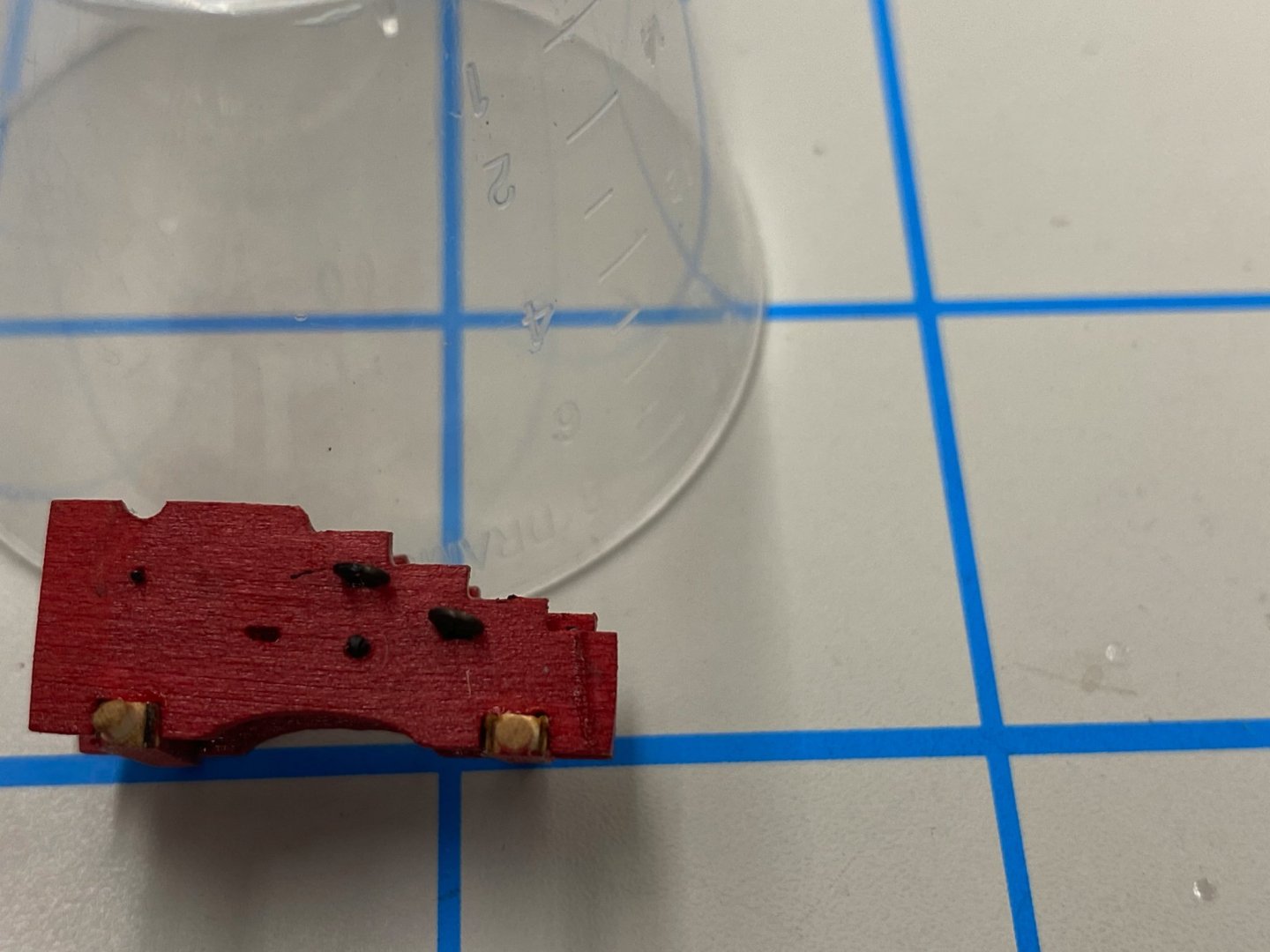
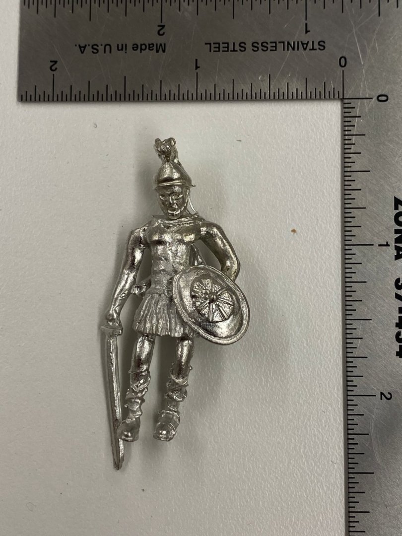
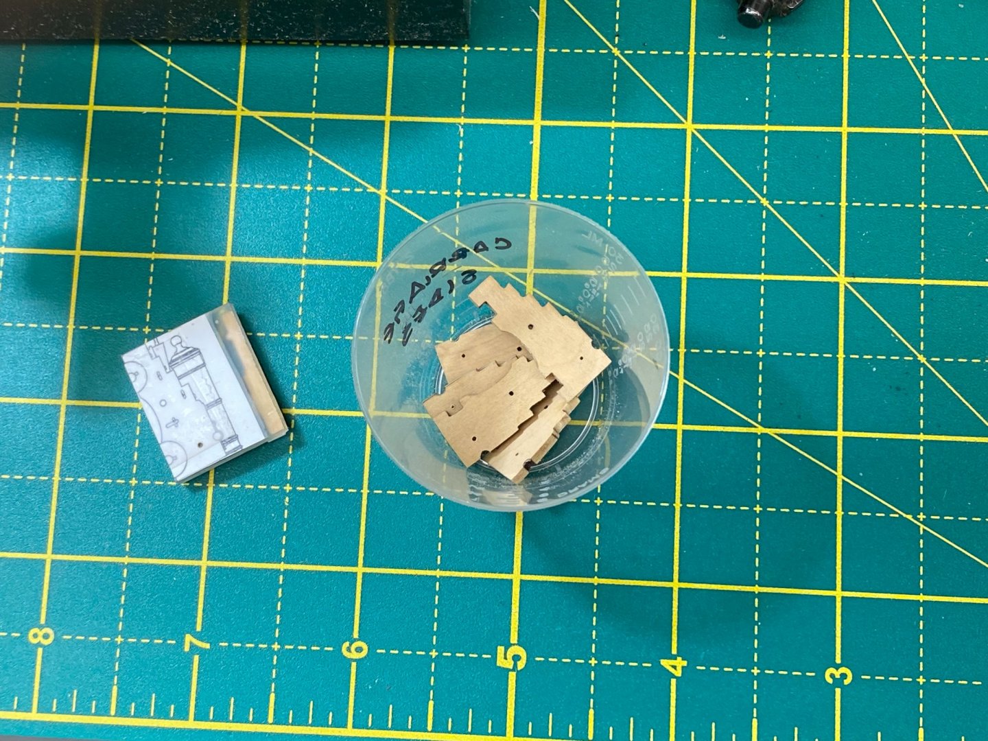
I am starting the Model Expo Confederacy kit and am struggling with painting the figurehead - picture below (and other Britannia metal decorations). The instructions say these decorations should be painted to look like wood. I also understand that early on (2009-2010) there were resin versions of these decorations but these are no longer available. So I am stuck with the Britannia metal versions. I have never had much luck painting Britannia metal parts. The paint (and I have tried oil and water based paints) does not seem to want to adhere to the edges of the item. Does anyone have experience painting items like this and have a "tips" that I should follow?
-
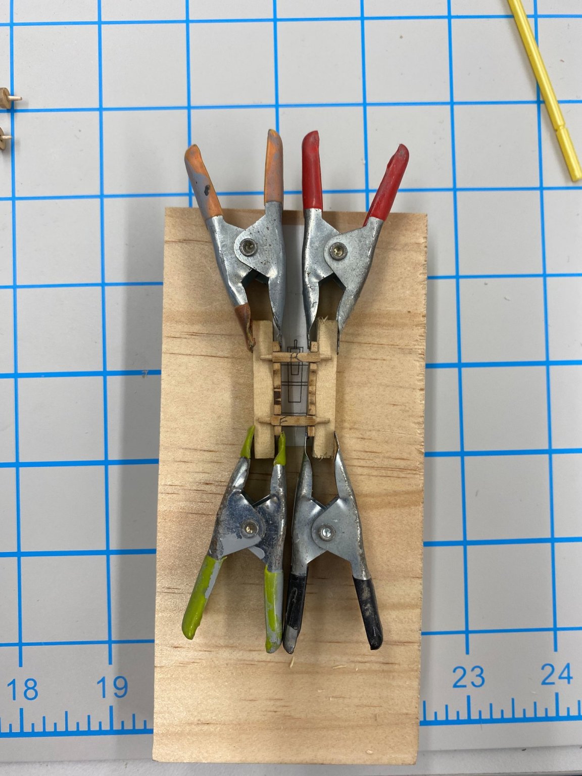
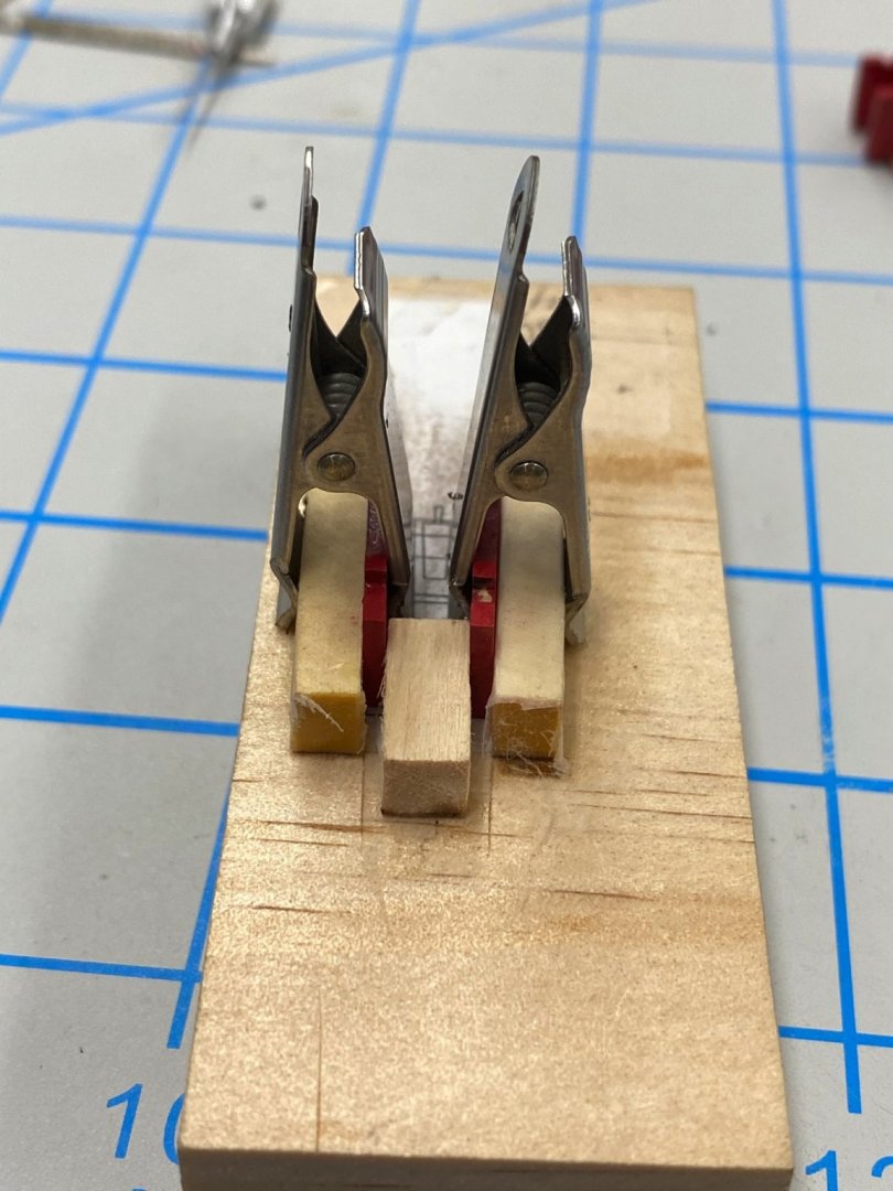
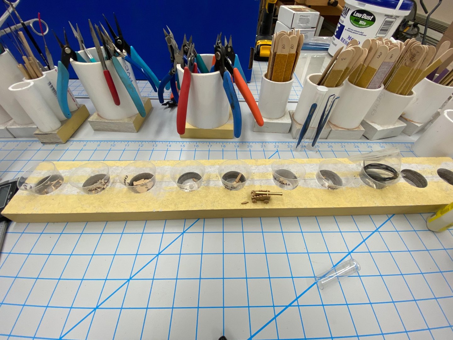
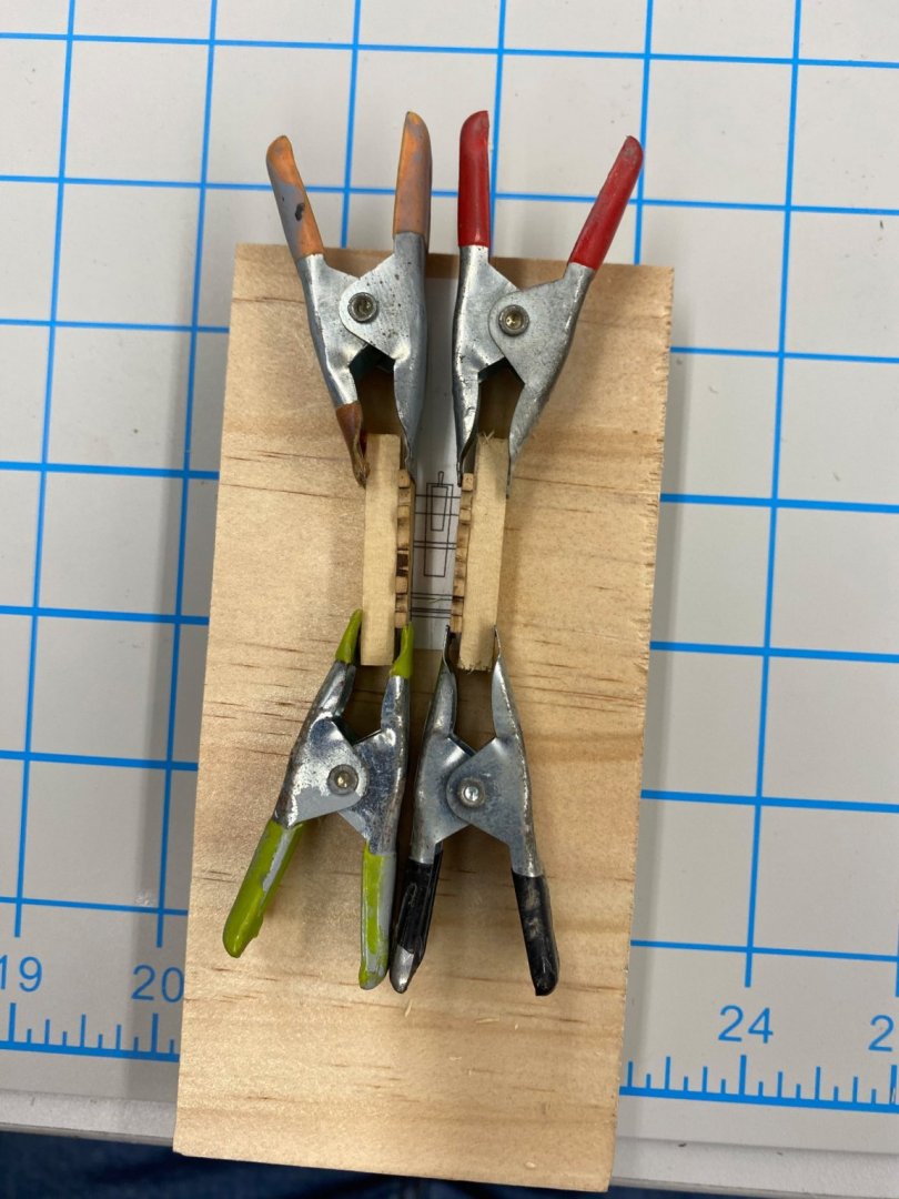
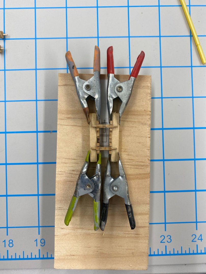
I have the cannon assembly line in "full operation. Since I showed it previously I have made a few changes to my carriage assembly "jig". Experience is always a teacher. I added supports at the rear of the jig to hold the rear of the carriage level with the lowest level of the carriage resting on the support. I also added a block at the front to hold the forward end of the carriage upright and snug to the outer jig support. Here is what it looks like with two carriage sides inserted. To keep the sides from moving I clamped them to the outer jig supports using some clamps I modified so they were narrow enough to not block the axle locations. Using medium CA I glued the front and rear axles into the slots in the carriage sides being as careful as I could to get the axle centered. If I had to do it again I would find some way to include a centerline marker and have marked the axle centerlines to make lining them up easier. In any event here is what comes out of this jig. So here are the 28 12-pounders - 26 empty carriages and two that I am using to proof out the next steps. While waiting for paint to dry I started construction of a build board. So far I have a 48" X 16" X 3/4" laminated lined shelf that I cut grooves in to mount two strips of "universal T-Track". I have not yet built the fixtures to go in the tracks or a method for holding the keel but it will be awhile before I need to use this.


- 370 replies
-
- 5
-
-
- Model Shipways
- Confederacy
- (and 1 more)
-
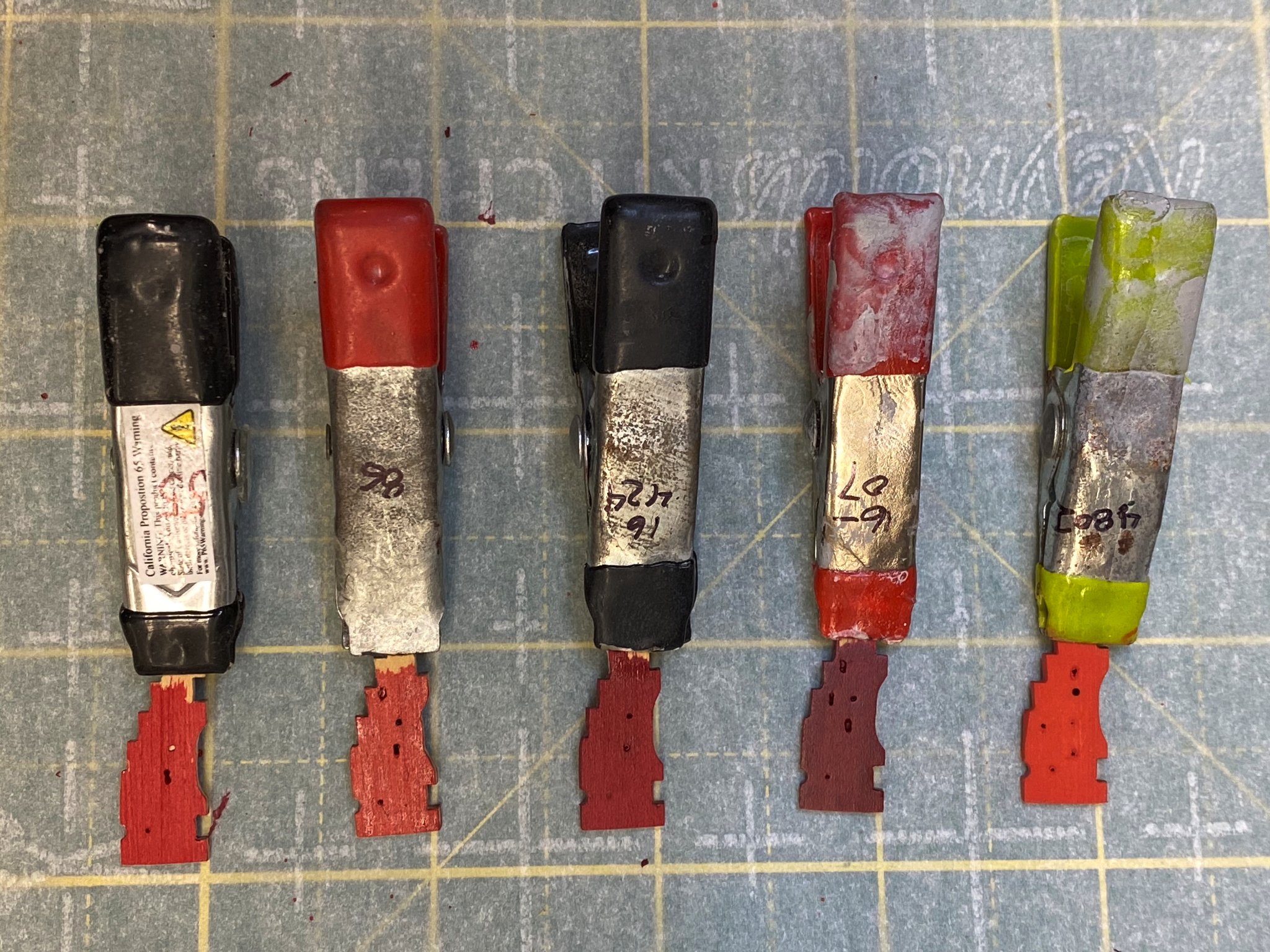
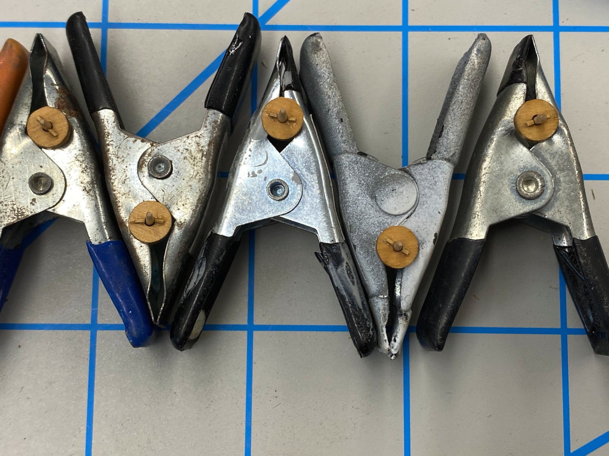
While taking a break from handling little, tiny pieces of wood I painted some of the "extra" carriage sides to try and see what "shade" of red to use for the guns and bulwarks. Here are five of the choices. The paints are a combination of Model Shipways, Badger and tru-color. Have pretty much narrowed the choice down to one of the two darker ones numbers 3 and four counting from the left (both are Badger paints, Windjammer Red and Signal Red). The left-most two (both tru-color paints) are "too red" and the right most has a bit of orange (much more obvious in real life than in the photo). I have one bottle of the Windjammer (and another on the way) and two of the Signal so that is not going to be a factor. I am leaning toward the Windjammer since it is between the "red red" of the far left and the closer to burgundy of the Signal Red. No need to decide today as I still have the rear carriage wheels to "key to their axles". Speaking of wheels here are the front wheels drying after a coat of tru-color flat. Did I mention you can never have too many clamps? I will leave the clamps in place to hold the rear wheels as that assemble/paint moves forward.

- 370 replies
-
- 3
-
-
- Model Shipways
- Confederacy
- (and 1 more)
-
And I thought drilling 350+ holes in the carriage sides was a challenge. That was child's play compared with adding the simulated wooden keys (or whatever the proper term is) that hold the wheels onto the axles. There are two per wheel and just over 100 wheels. The instructions for assembling the carriages refer to using "the smallest of wood shavings" glued to the axles (after the wheels are installed. I took a different route and glued my simulated keys to the wheels so I could do it before assembly. Since I have not put one together yet we will see if this makes a difference although I suspect there will be cases where my methodology does not serve as well as Chuck's. To make the simulated keys I started with a 1/32 X 1/32 boxwood strip and reduced the thickness on one side to about 1/64". I used an chisel blade on an Xacto knife to split the 1/32 side roughly in half so ended up with a series of short (the width of the Xacto blade) 1/64 X 1/64 pieces which I then cut (using the same chisel blade into short lengths using the width of one of the dividing lines on the cutting mat as the "standard". The trick was getting a small enough spot of glue on the wheel so the key would stick but not "swim" around in the bubble of glue. I finally used a small detail brush to get any bubbles out and spread the glue thinly on the wheel since there is no load on the joint - just gravity trying to pull the key down off the wheel. I started using WEldbond glue but switched to straight up white glue after I had none a half dozen or so as the Weldbond is a little thicker and dries quicker so I had to keep adding a fresh blob from which to get a small drop. I used four different sets of tweezers to handle the keys as I kept getting glue on the tips and the keys would stick to the tweezers not the wheel. A pair of tweezers were good for one to three wheels and then by the time I cycled through three more sets the glue on the first set had dried enough that they were again usable. Here are a few of the "keys" and a front wheel with the keys installed. I intend to leave the wheels their natural color (no stain) but apply a coat of clear flat so hopefully any dried glue residue will not be terribly noticeable.
- 370 replies
-
- 3
-
-
- Model Shipways
- Confederacy
- (and 1 more)
-
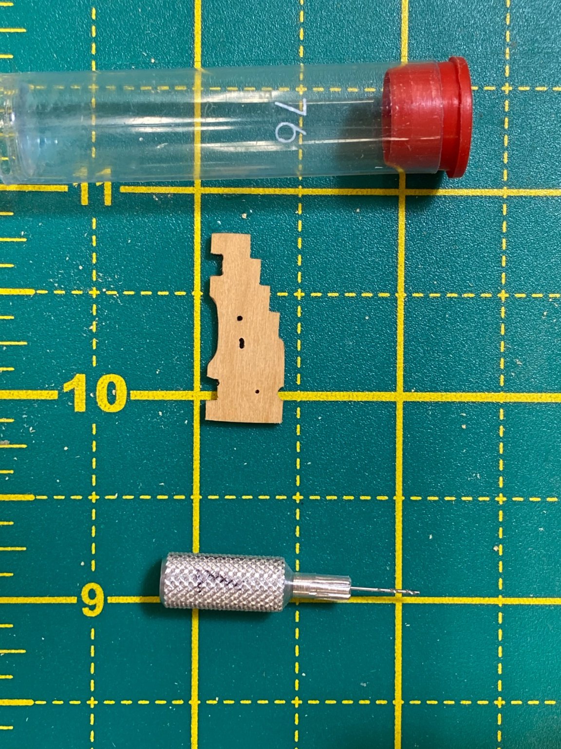
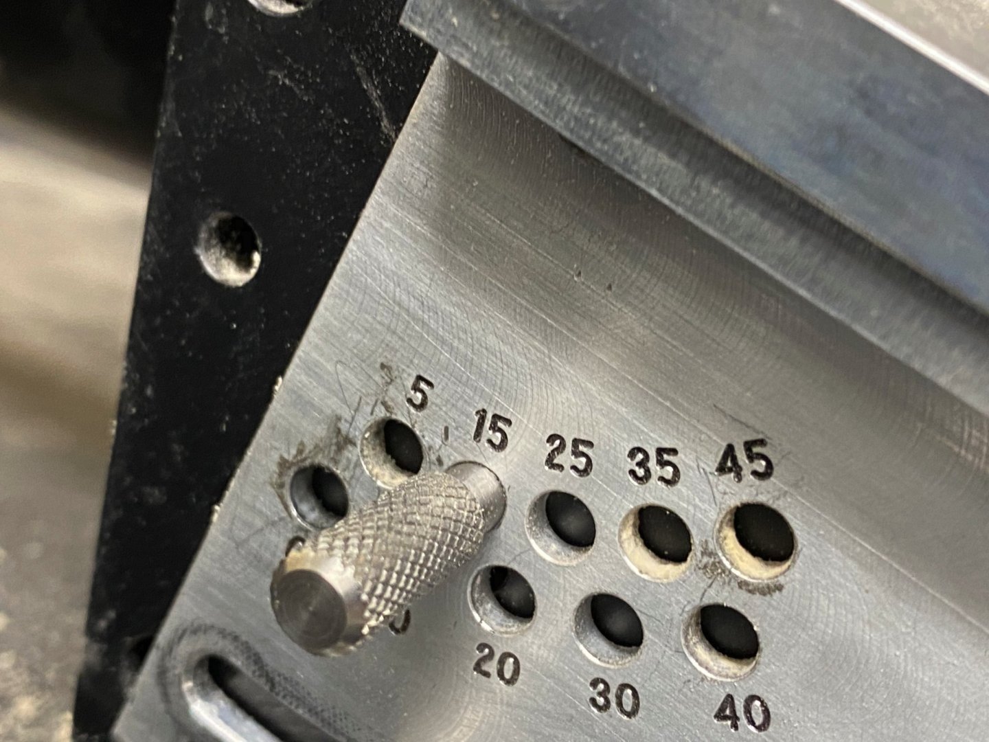
It was worse than I had thought. After several false starts on getting the eyebolt holes to allow the eyebolt to be recessed a small amount in the carriage side I finally decided to drill two holes as close as possible with a #76 drill bit and then use a #76 bit to remove the bit of wood between the two holes to make a slot. The x-y axis adjustments on the drill press are marked with a total of 50 increments (units not specified, possibly .001" but...). By trial and error I found that about 30 "units" was as close as I could drill two separate holes. Any closer and the drill bit (in spite of having less than 1/2" exposed outside the chuck) would wander into the hole already drilled. I decided that I did not have to be overly exacting about getting the sides of the slot completely straight since the eyebolt is going to hide most of the slot (hopefully). Here is my first acceptable "slot". This eyebolt would hold the ring that the breeching line runs through. Also shown is the #76 hand drill bit I used to remove the wood between the two holes. So, rather than one hole for each of the three eyebolts on each carriage side I had to drill two and they had to be a specific distance apart. Much fun was had by all. So here is what a carriage side looks like with all the holes drilled, the two round holes are for rods that hold the gun carriage and transom and the three slots are for the three eyebolts on each side (even though only two of them are used - at least according to the instructions). After all that "fun" drilling the holes for the simulated bracket bolts was a piece of cake. Here is one carriage side with the three bracket bolt holes completed. Now it is time to assemble some carriages - I think, better check the instructions again.

- 370 replies
-
- 4
-
-
- Model Shipways
- Confederacy
- (and 1 more)
-
Chuck & Bossman - thanks I will try and provide a "gem" of a model.
-
Since this is supposed to be an "Admiralty" model I decided to try and make things as consistent as I am capable of. So I made another jig to locate the holes to be drilled for the eyebolts in the carriage sides. The jig holds the carriage side securely and is held in the drill press vise. I taped a copy of the drawing to a piece of thin plexiglass then used the disc sander to get it aligned with the jig in the drill press. Using the x-y table on the drill press I lined the drill over the hole that is just under the cannon barrel. Here are some pictures of the jig and template. The "bad" news is that there are four holes that need to be drilled in each carriage side so each of the 56 carriage sides has to go through the jig four times. And that is before we consider the three bracket blots in the top of each carriage side. I will made a jig for that too but until I get the 224 holes drilled in the sides.


- 370 replies
-
- 5
-
-
- Model Shipways
- Confederacy
- (and 1 more)
-
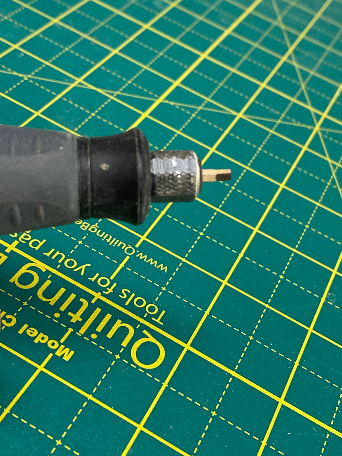
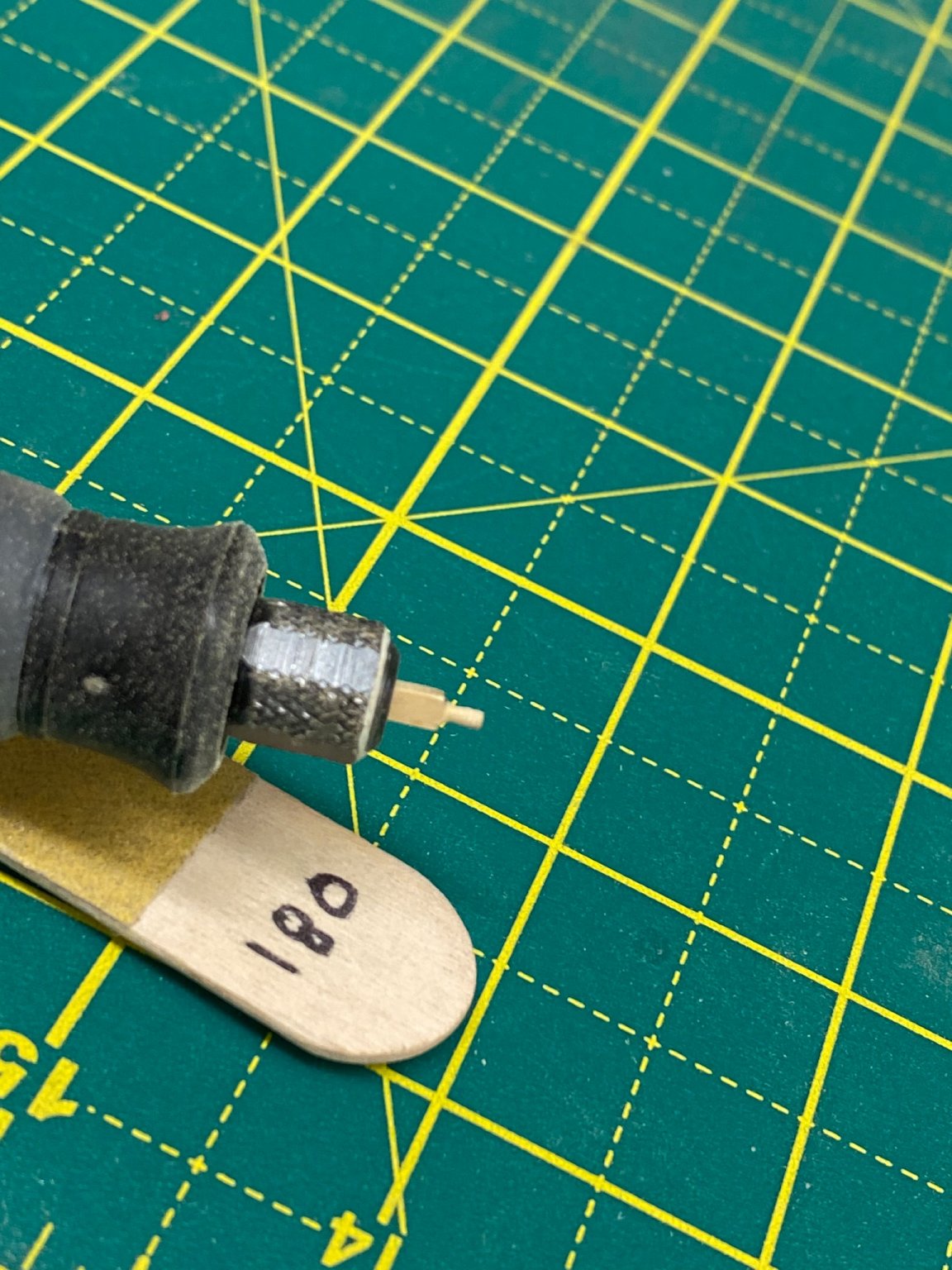
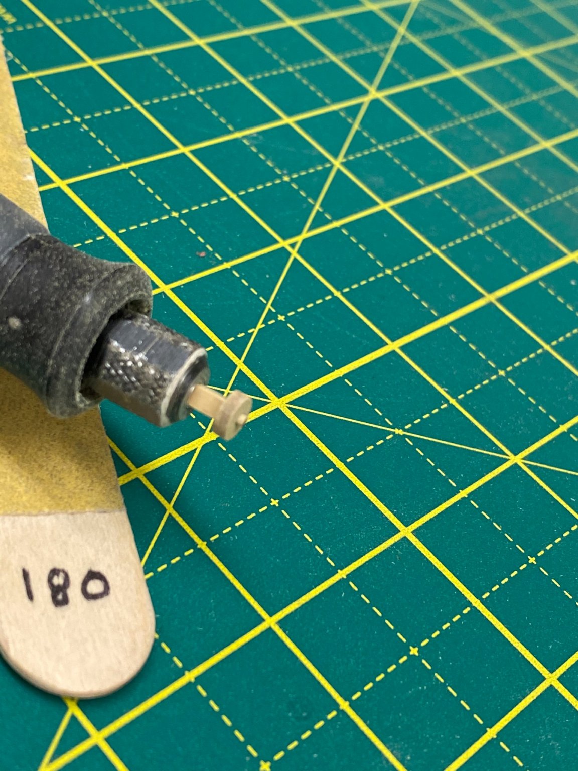
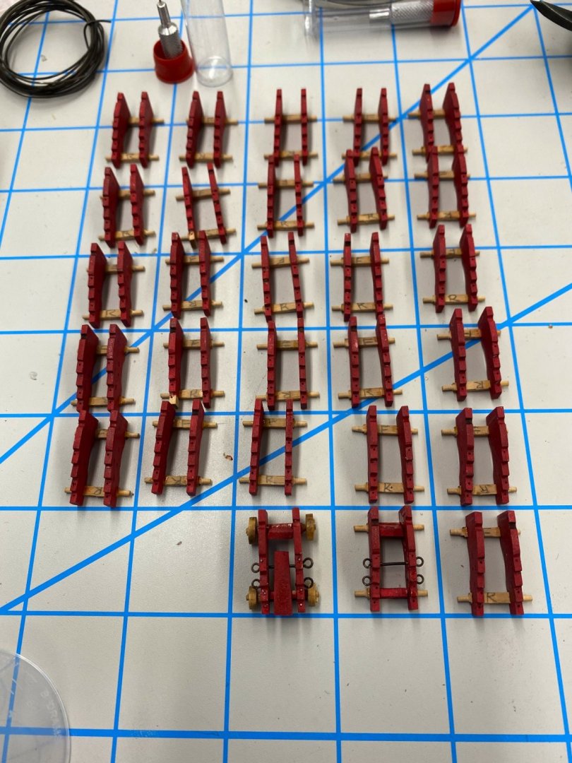
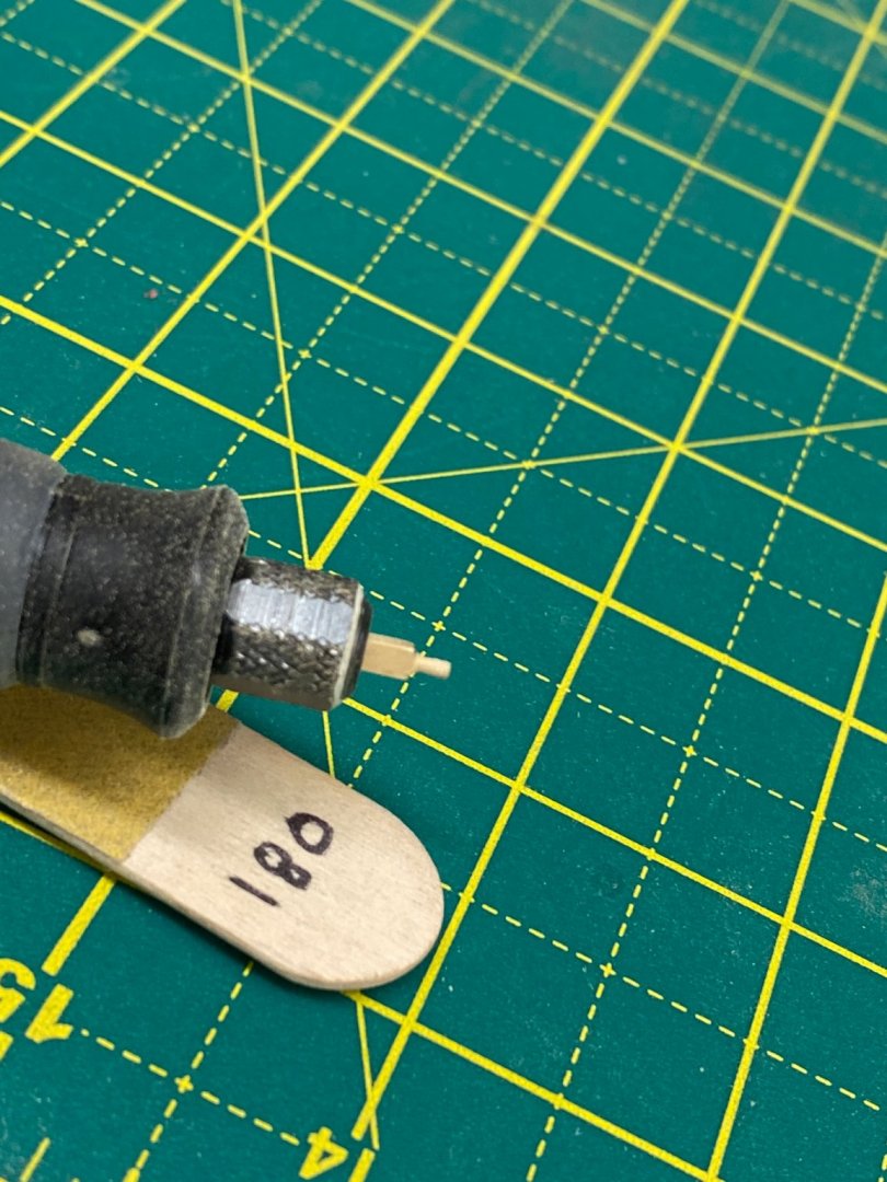
I decided that I should probably set up some kind of "production line" to get the 28 12 pounder carriages built and outfitted per the instructions. Since I have a few spare carriage kits (and am sure Chuck will sell me more) I completed the first as a prototype, less all the outfitting (bolt heads, eyebolts, etc.) Here is my prototype - the cannon is just sitting there but all the carriage elements are glued together. I used a previously created jig I usually use for holding rigging blocks and such to "bin" the pieces from the laser carry sheets after the laser char has been removed and the axles turned to round. Here is my "production bins" with the other three sets of components from the first set of four. For the quion handle I used a small brass belaying pin with most of the pin cut off. I had to drill a #68 size hole in the back of the quion to fit the belaying pin but it does not have to be very deep. I did not even have to use any glue, at least so far. For those who may not have understood my method for turning the axles round here are some pictures of the square axle in the Dremel handpiece, the same axle after rounding and with the wheel (a rear wheel in this case) on the axle. I used the 180 grit sanding stick to round the axle. It took about 20 seconds of fairly light pressure to get it down enough to fit the wheel.


- 370 replies
-
- 6
-
-
- Model Shipways
- Confederacy
- (and 1 more)
-
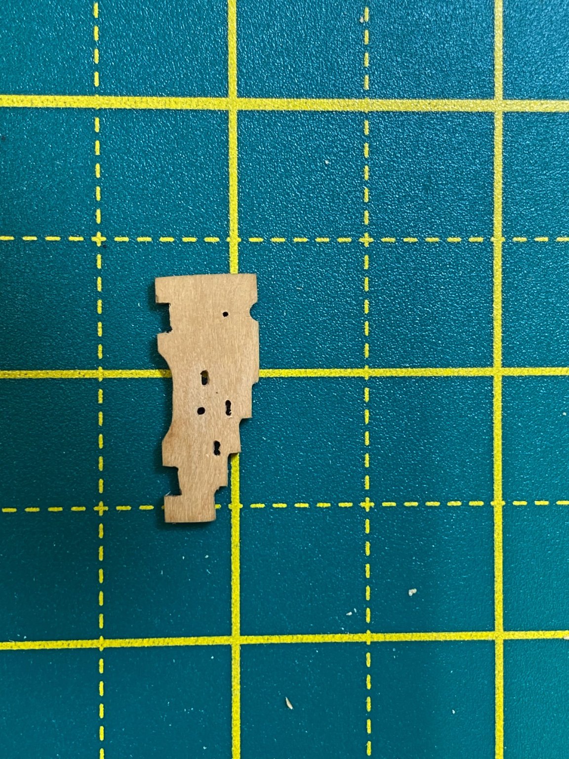
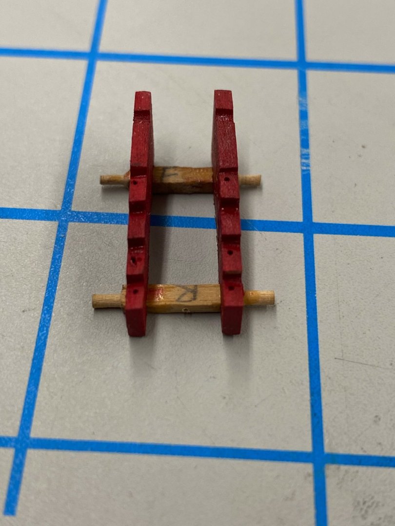
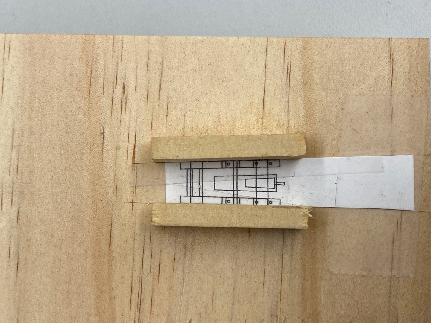
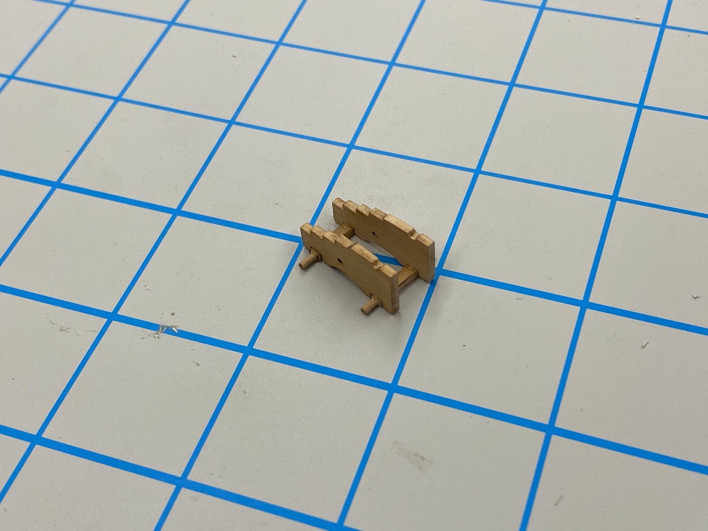
So decided to get started on the gun carriages since there are 36 of them (28 12 pounders and 8 6 pounders). That and over 100 sets of gun tackles. I am using the cannon and carriages from Syren Ship Models rather than the kit provided ones as the Britannia metal cannon are quite rough and even though they are going to be painted I wanted to have the carriages made from boxwood instead of basswood. So I downloaded and printed the plans (you get the plans for all three carriages they supply on one sheet) from Syren for the gun carriages. I took the pieces for one 12 pounder carriage from the laser cut sheet and cleaned off the laser char. I decided since were so many of these (I thought the guns on the Niagara were a challenge) that I would need a jig to help with assembly. The Syren instructions would have you paint all the pieces before assembly but I think I will get the basic carriage assembly together before I start painting. I taped the top view of the carriage plans to a small piece of pine and carefully cut along the outer edge of the carriage sides and glued a piece of scrap wood that did not extend above the axle notches on each side. This is what it looks like. I used four small clamps to hold the two carriage sides against the sides of the jig. Getting the carriage exactly on the drawing and at the correct height (only the rear portion of the carriage is at full height - it is easy to get it in sloping forward) took some practice but eventually here is what I had. I took the two axles (and marked which was which since the rear one is slightly longer than the front) and using a minimum of glue attached them to the carriage sides in the notches provided. Before gluing them in I chucked the axles in my Dremel handpiece and used a small file to round the outboard portion of the axle so the wheels will fit on. You have to remove almost half the material on the axle so this is much faster than trying to do it by hand. Here are the axles glued on. Before I do the next carriage I will put some scotch tape along the inside and outside of the jig sides to reduce the likelihood of gluing the carriage to the jig. So here is the basic carriage sides and axles as a unit. I think I will get them all to this state and then paint them.
- 370 replies
-
- 3
-
-
- Model Shipways
- Confederacy
- (and 1 more)
-
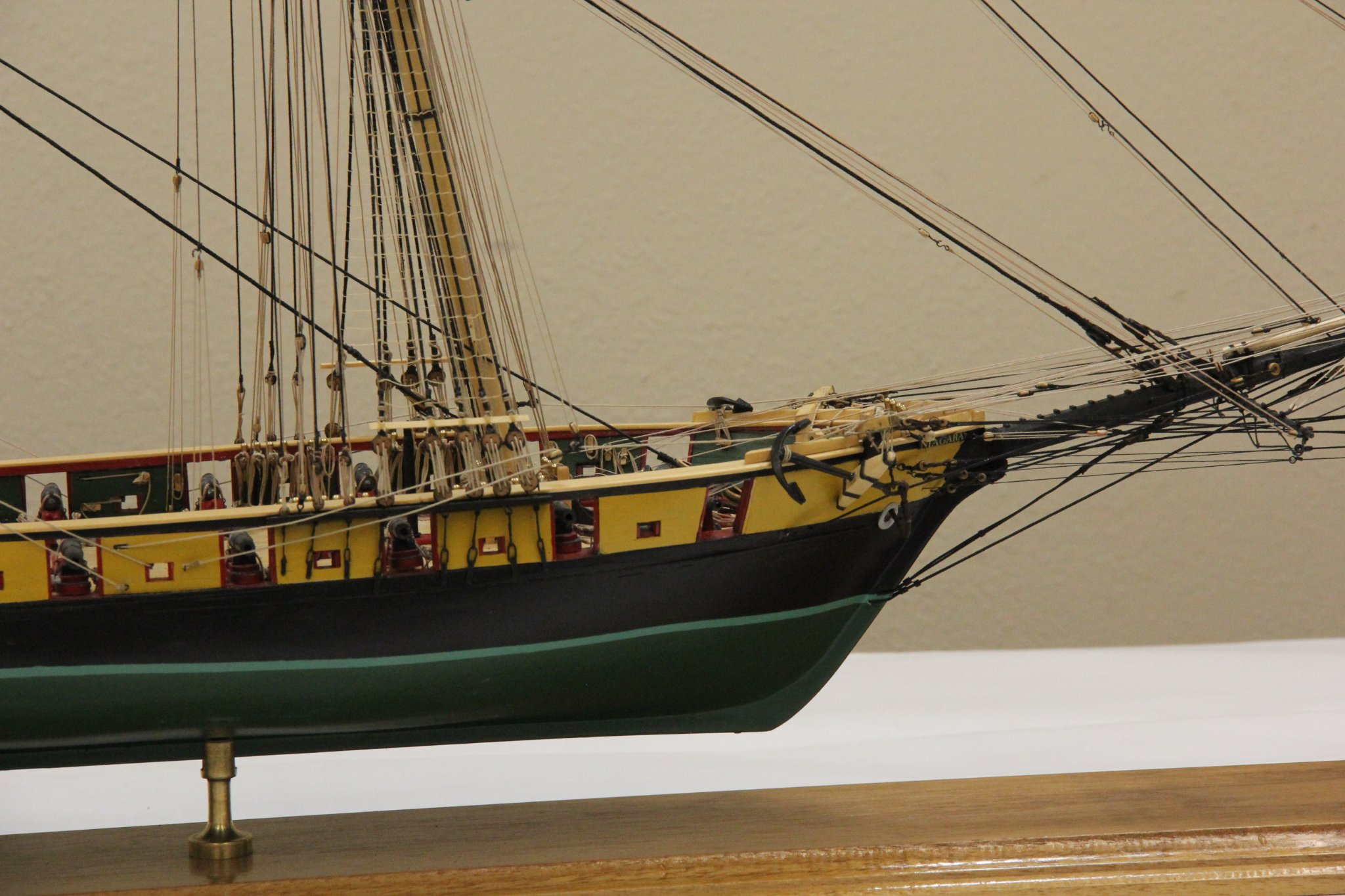
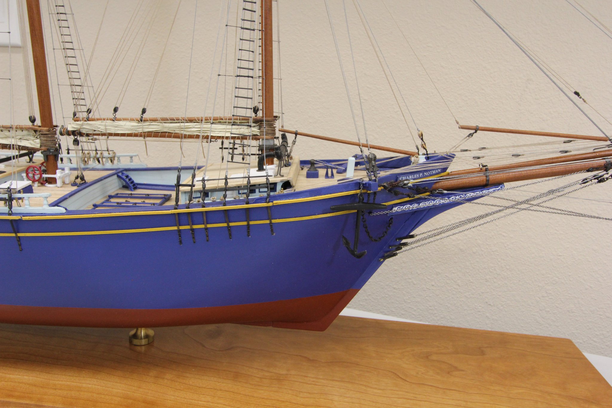
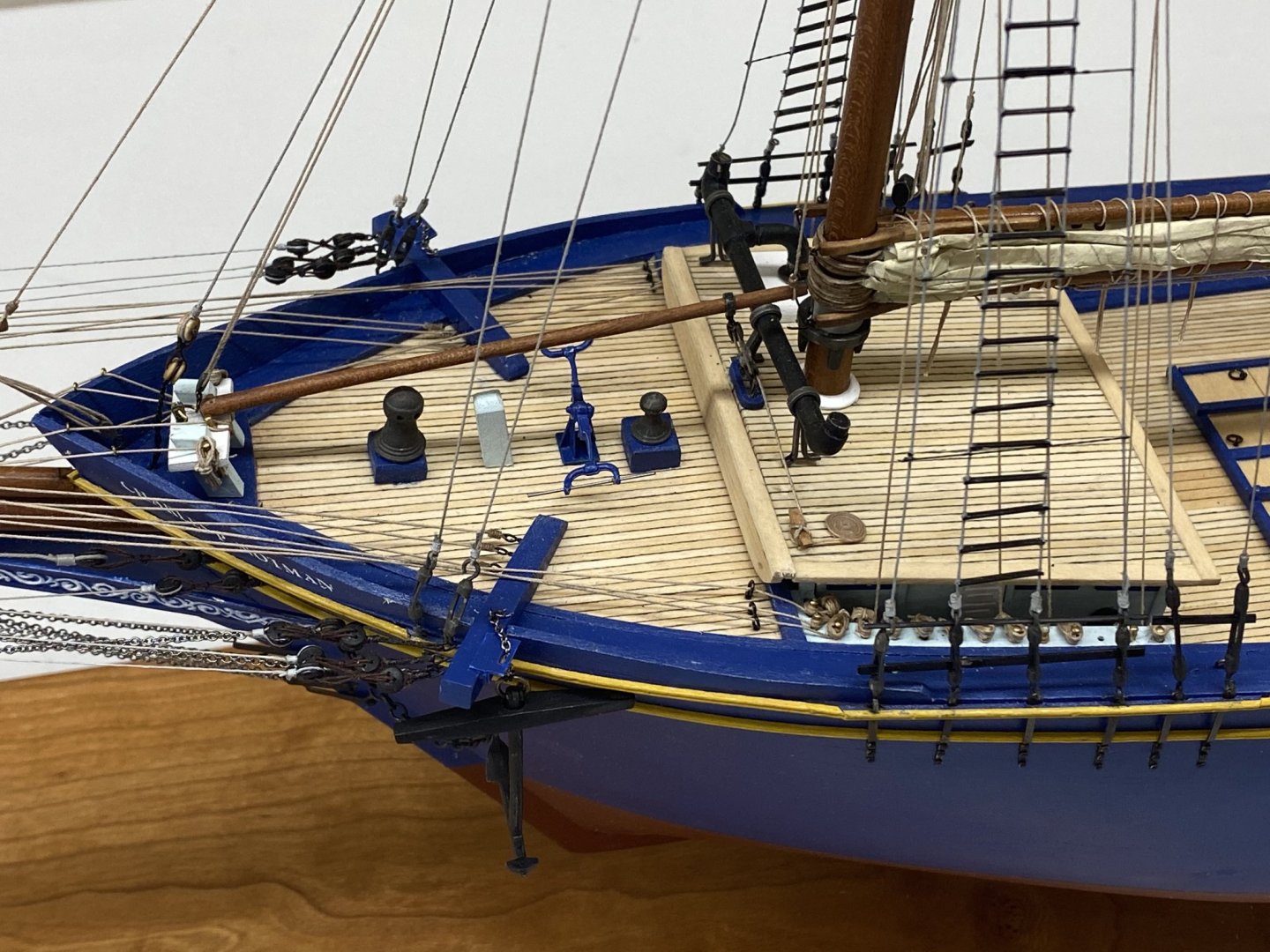
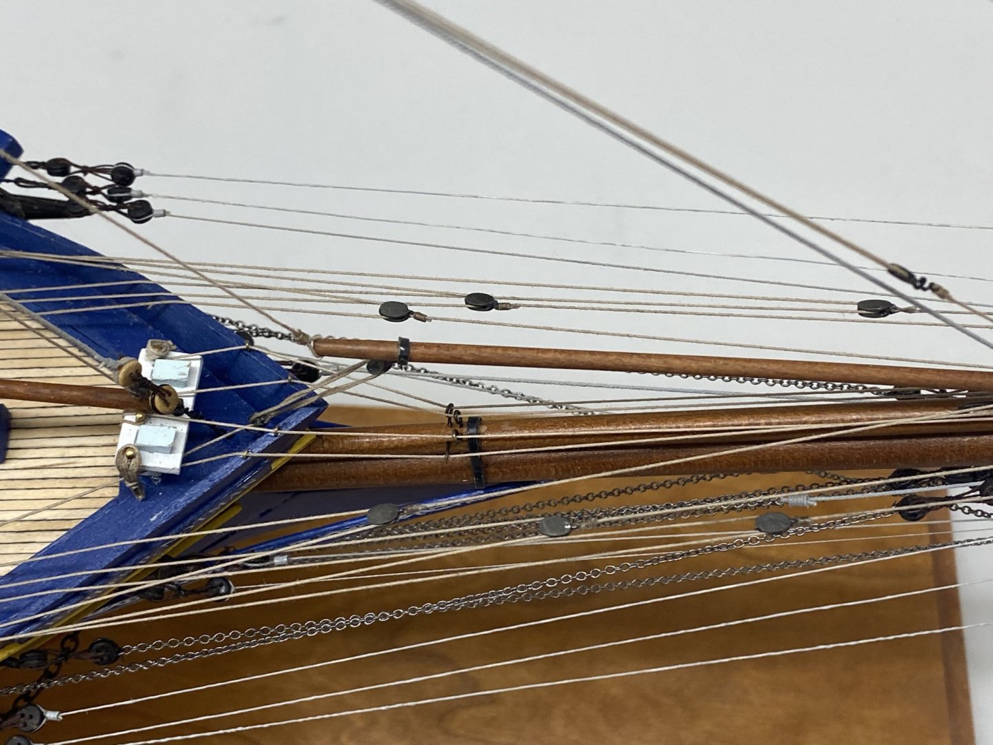
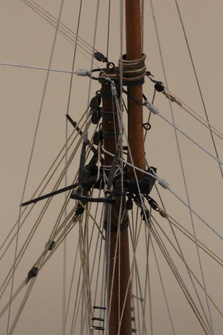
The anchors would not be hanging free if the ship were underway. The drawing provided do not show the mechanism which would "house" the anchors. At the very least there would be a cleat somewhere inboard that would secure a line that would be secured around the anchor shaft generally just above where the flukes are. There would also probably be a thicker main rail under where the shaft of the anchor sat on the rail. Here is a picture showing the anchor on my model of Niagara. I thought about including something similar on the Notman but was "in a hurry" to start the next project so maybe in its first refit.

- 144 replies
-
- 3
-
-
- charles p notman
- finished
- (and 1 more)
-
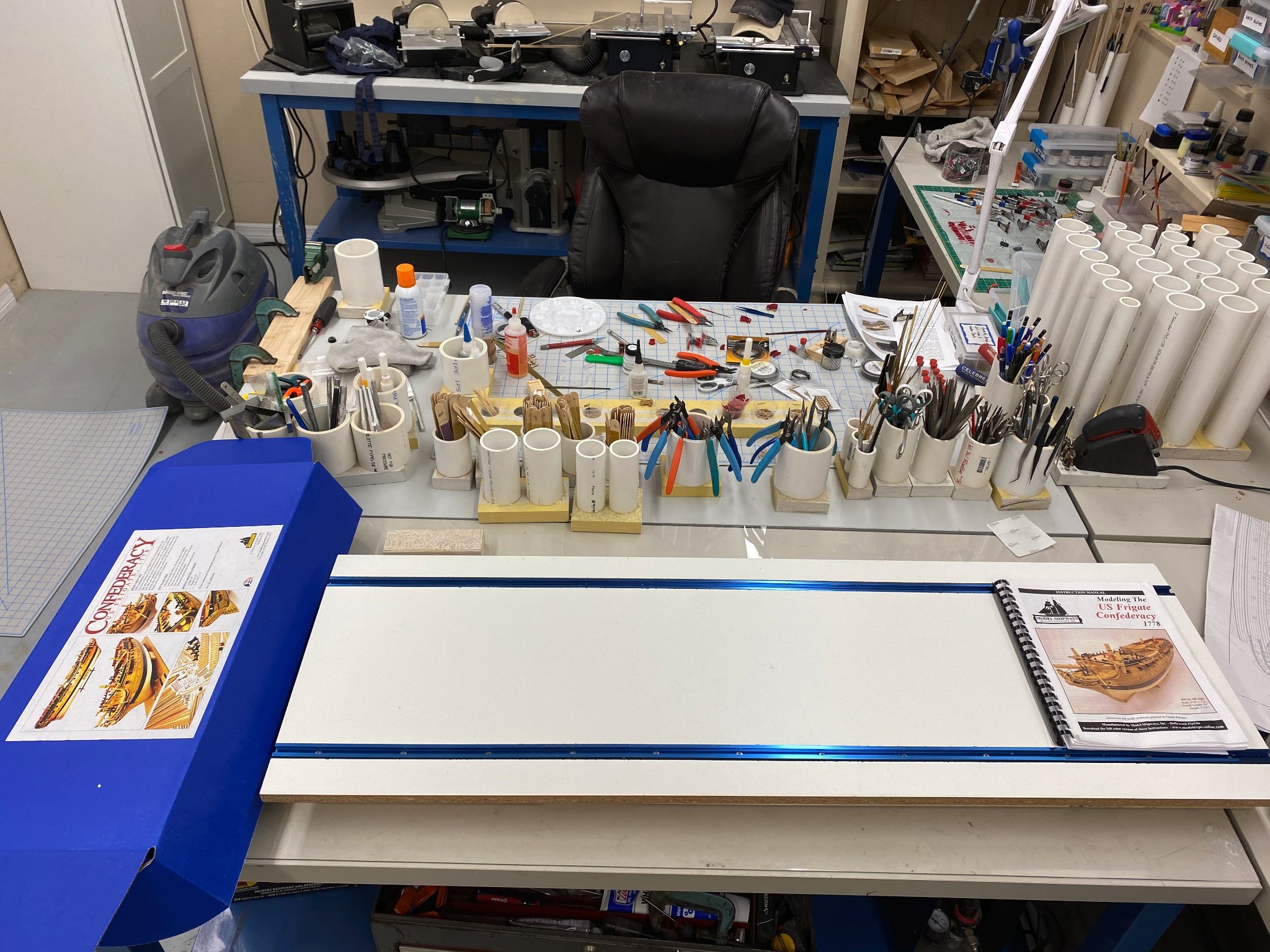
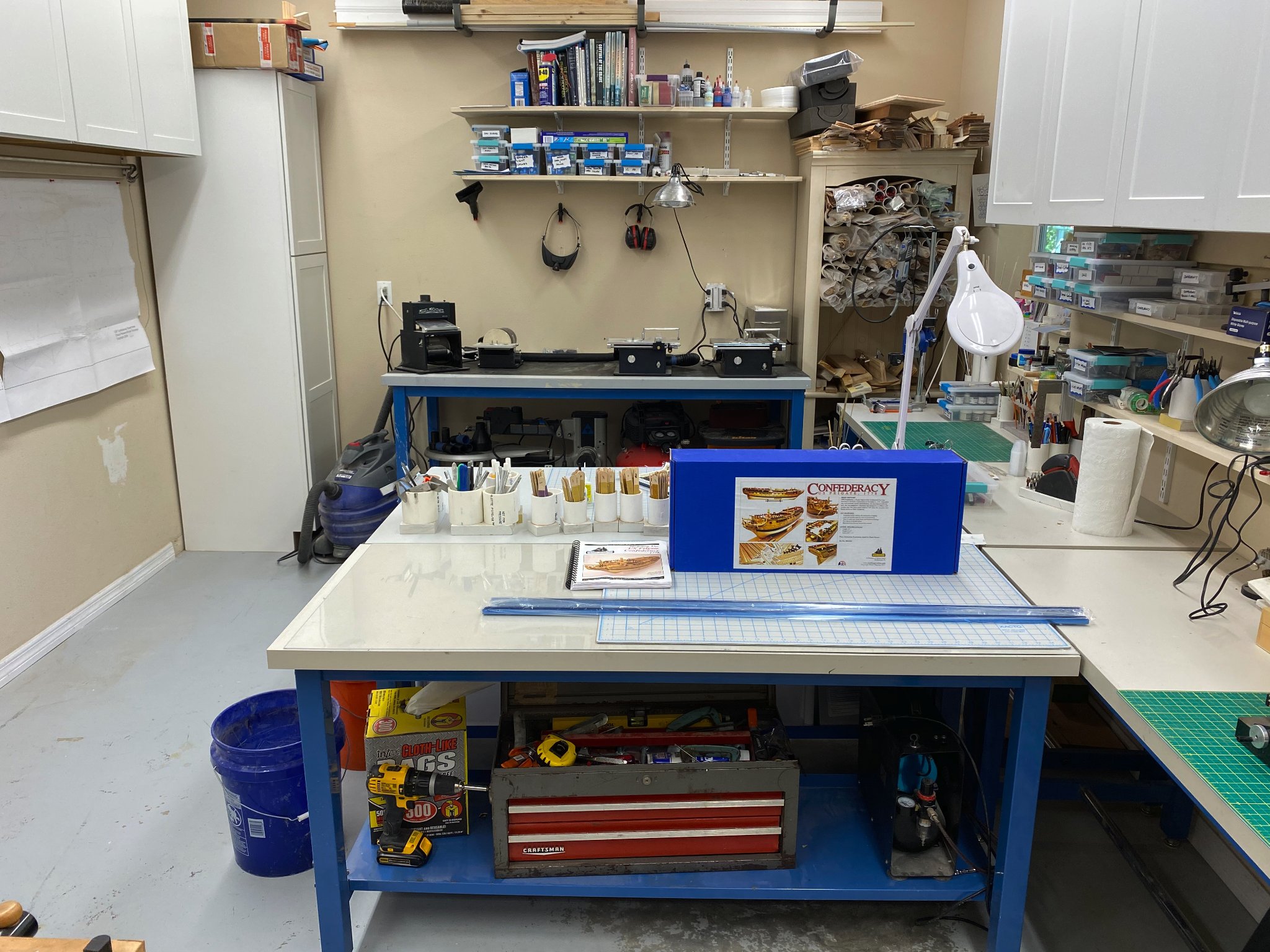
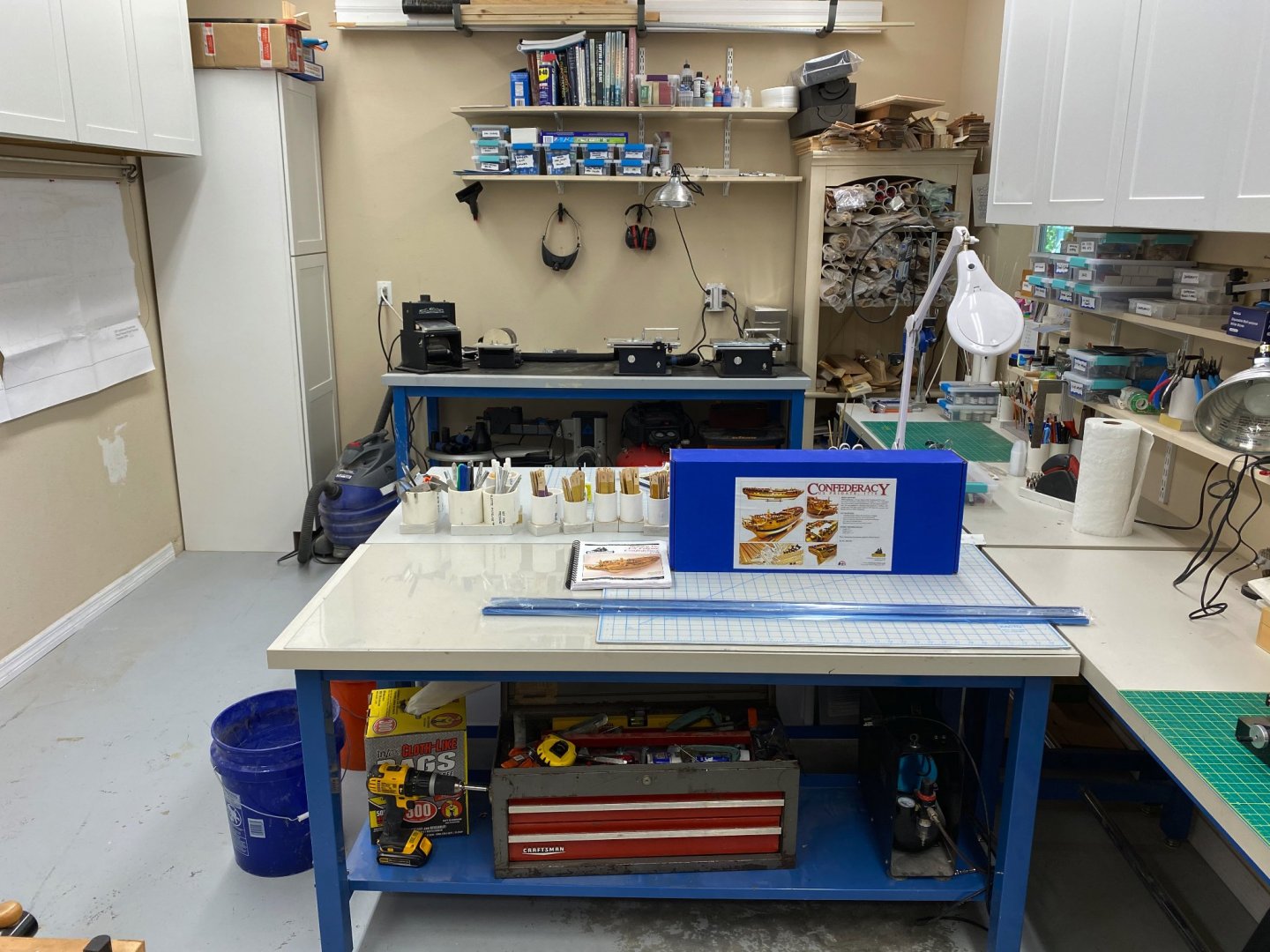
I am starting the Model expo Confederacy but plan on incorporating some (maybe all) of the Swiss Pear framing and other material supplied by the Lumberyard. The Lumberyard materiel will not be here for a couple of weeks so I plan on starting either the ship's boats or the guns (using Syren Ship Modeling cannon and carriages) or maybe so outside "house" work (it IS getting cooler here in Florida) until it arrives. In any event here is the obligatory work bench and kit box picture. The two blue "things" are the "T-Tracks" that go on the build board that I have yet to fabricate.
- 370 replies
-
- 5
-
-
- Model Shipways
- Confederacy
- (and 1 more)
-
Bruce, I am going to start my Confederacy shortly and am going to review your log in great detail as I get started. Hope I can do as good a job as you have done. I have never planked a hull that was not painted and thus have used Bondo and wood putty to "cover my sins". Hopefully I will be able to at least "do better" on the Confederacy.
-
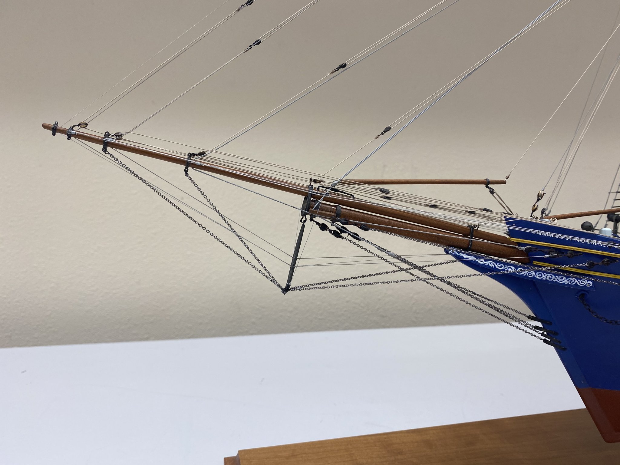
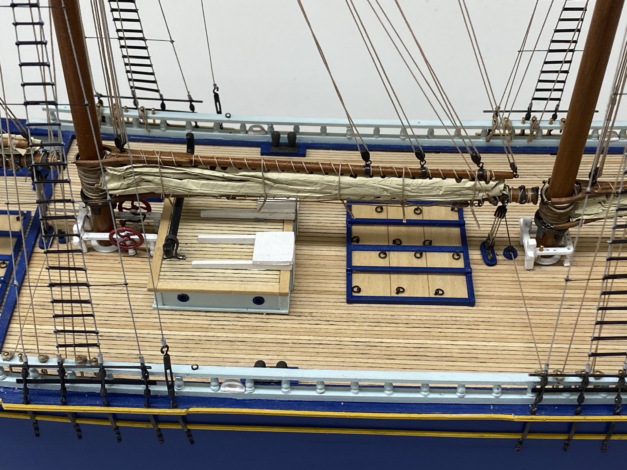
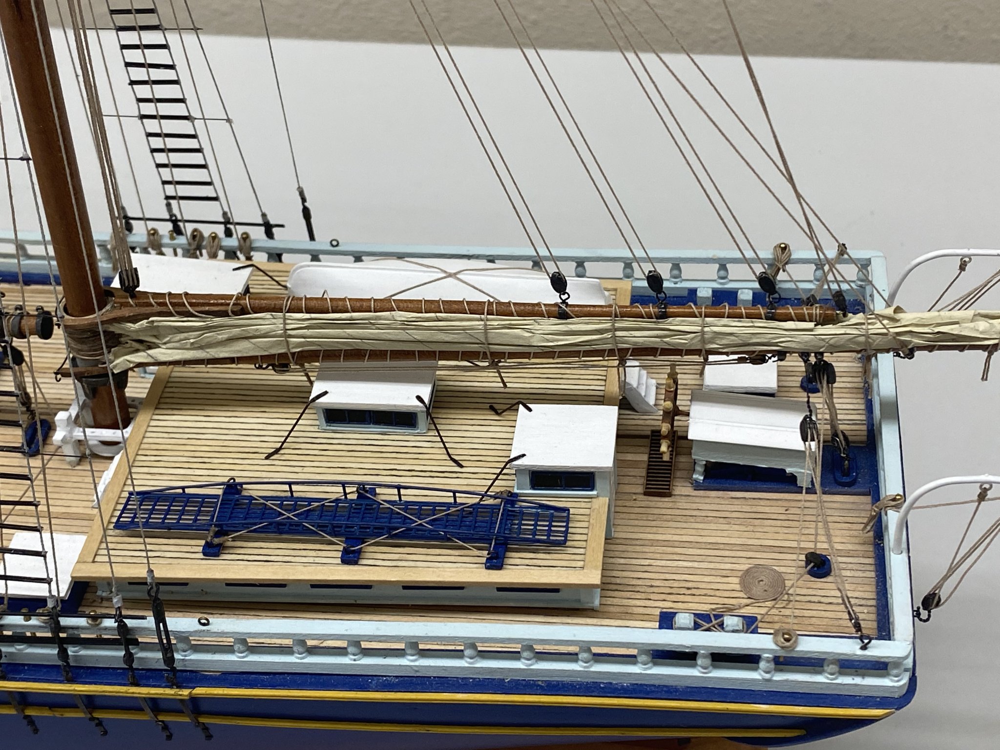
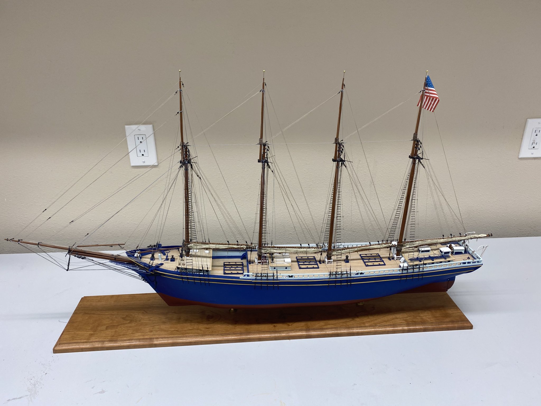
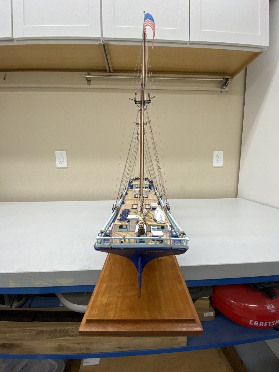
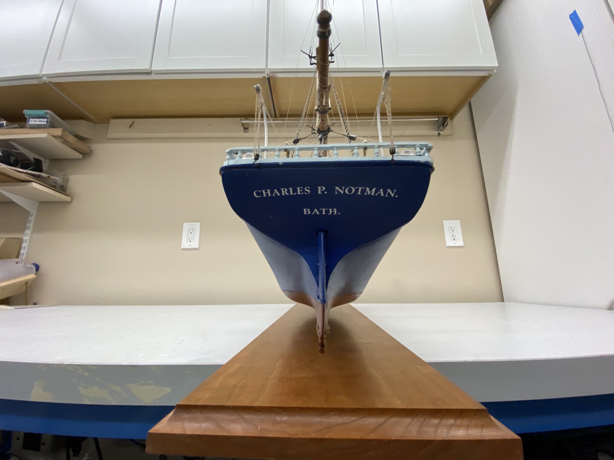
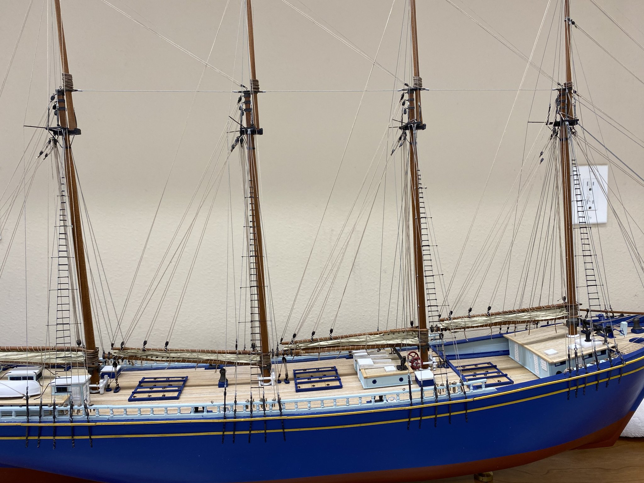
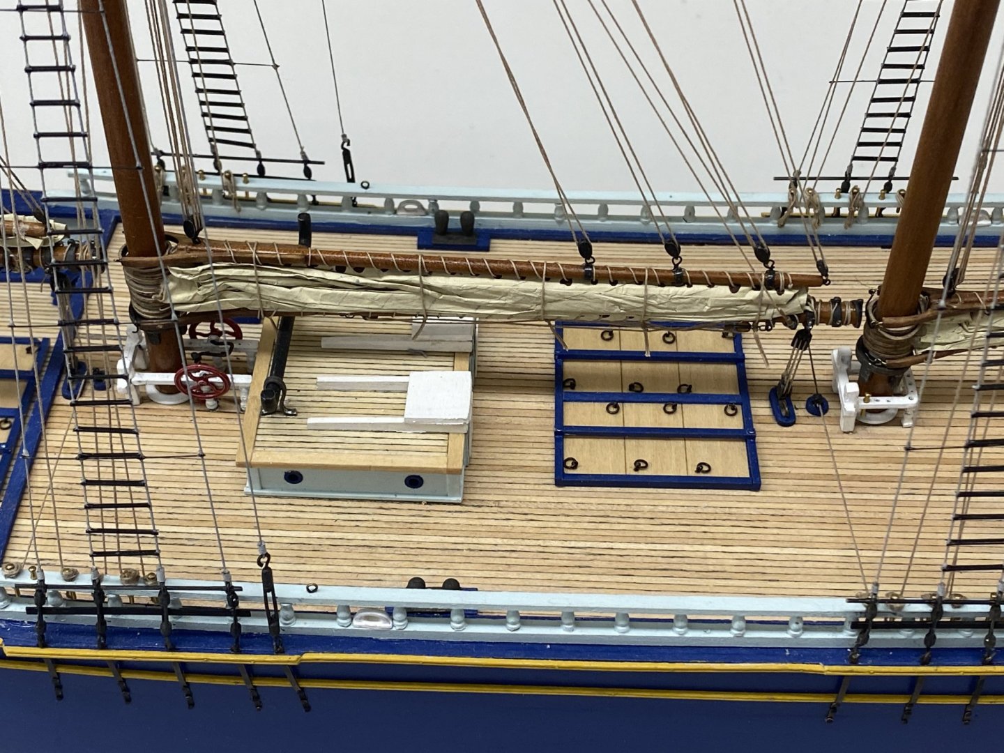
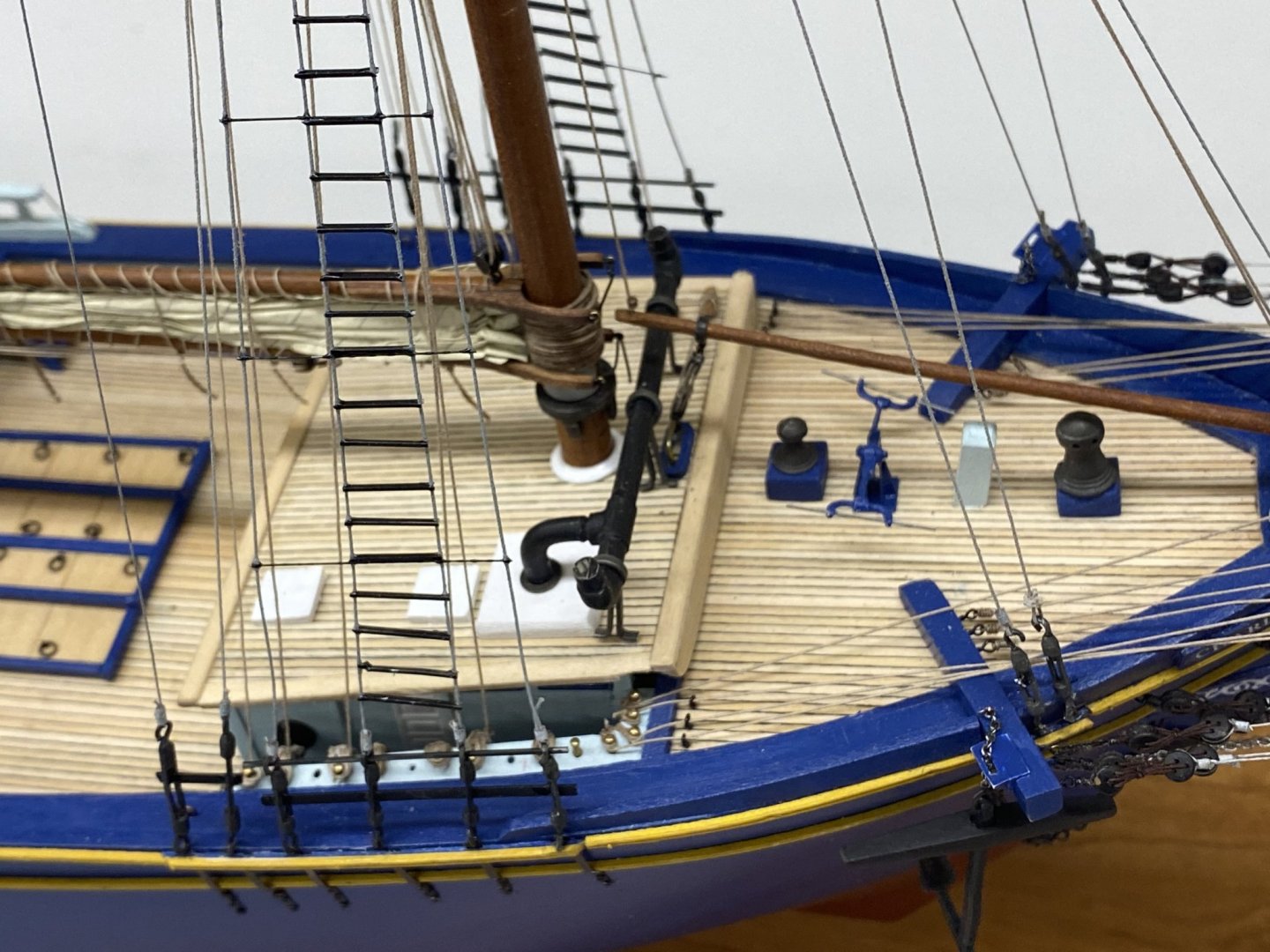
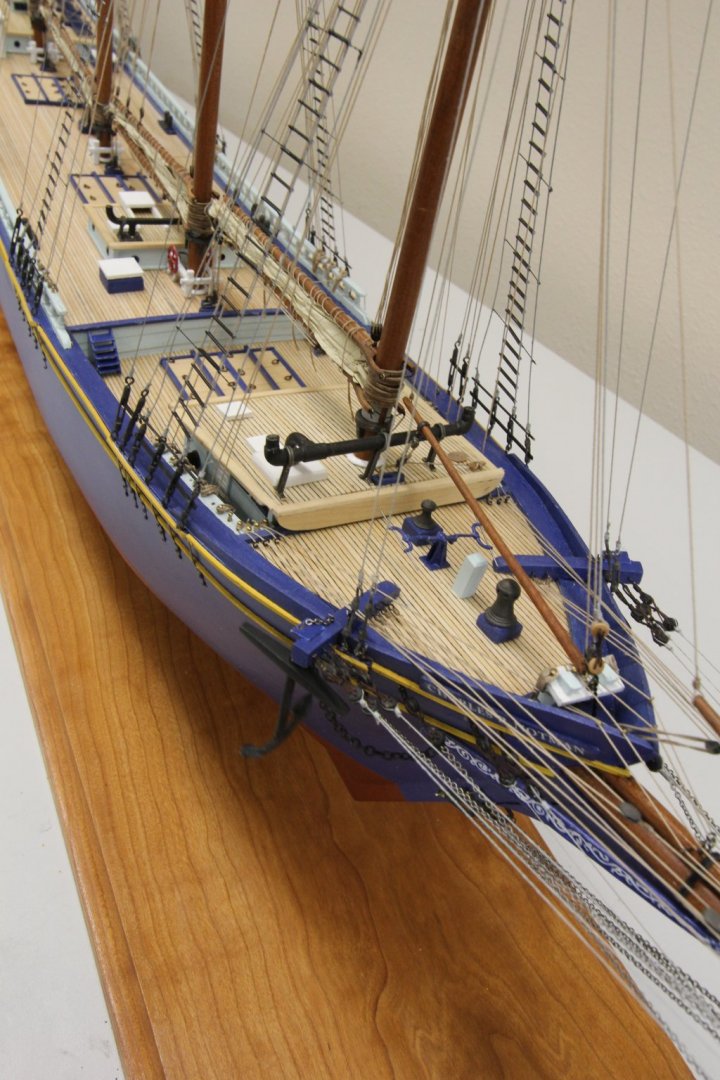
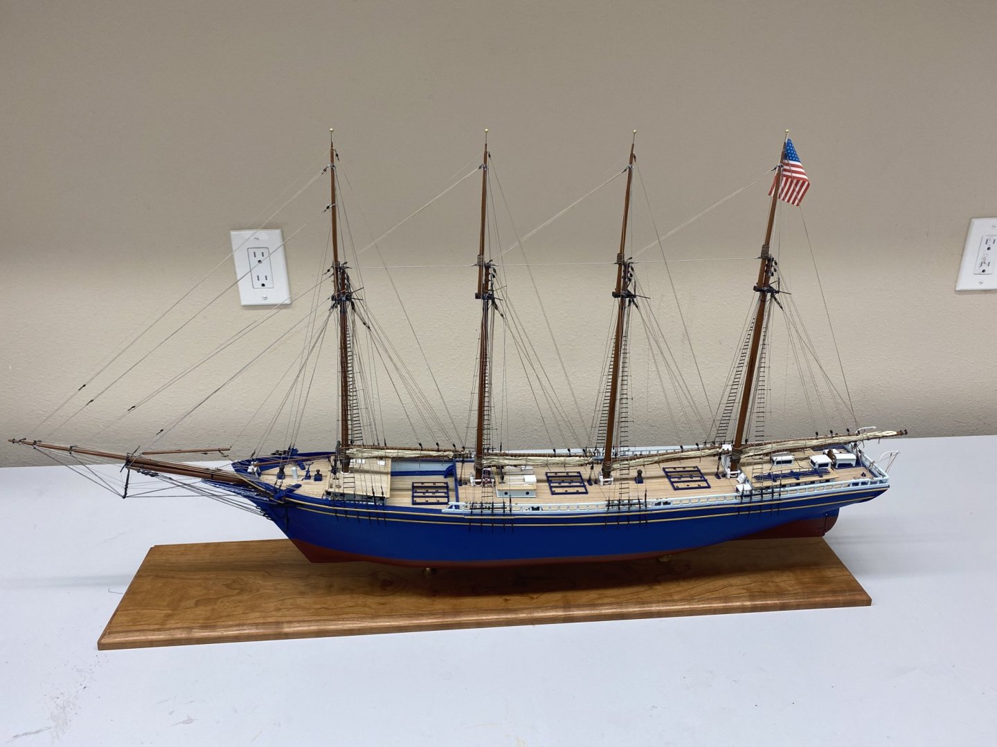
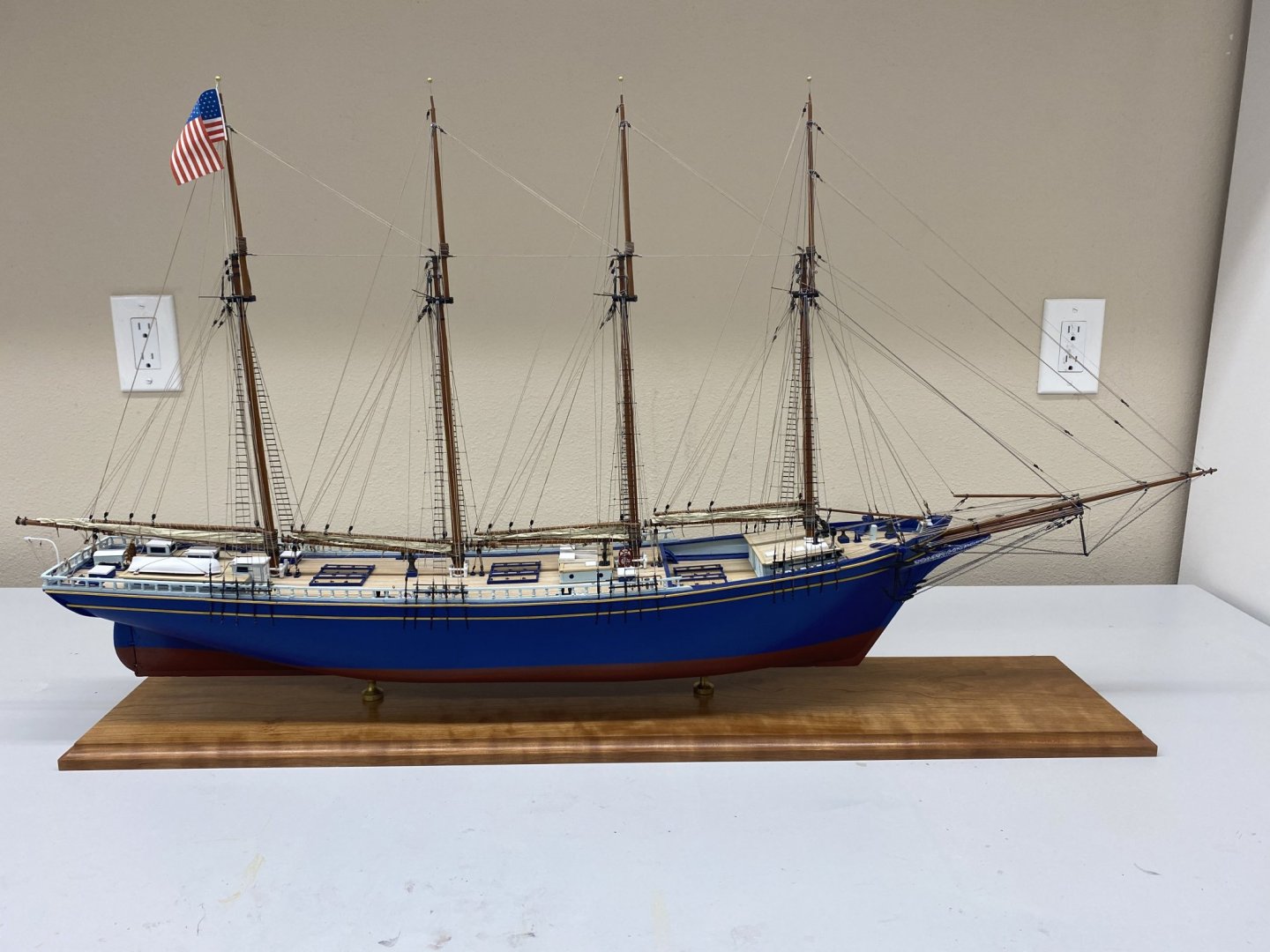
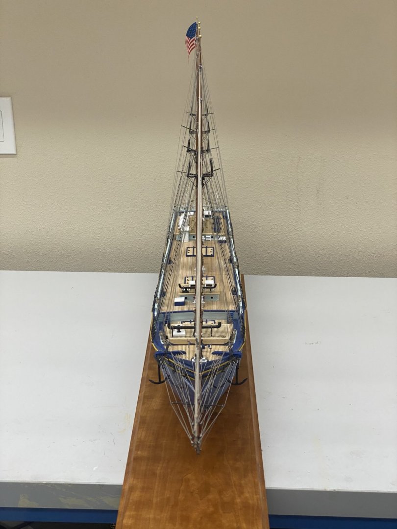
John, Clare, Mike, Bob - thanks for the kind words. As promised here are some more pictures of the completed Charles P. Notman. If anyone wants a shot of something specific or info on what or how some feature was fabricated just reply and I will attempt to provide whatever I am able.


- 144 replies
-
- 8
-
-
- charles p notman
- finished
- (and 1 more)
-
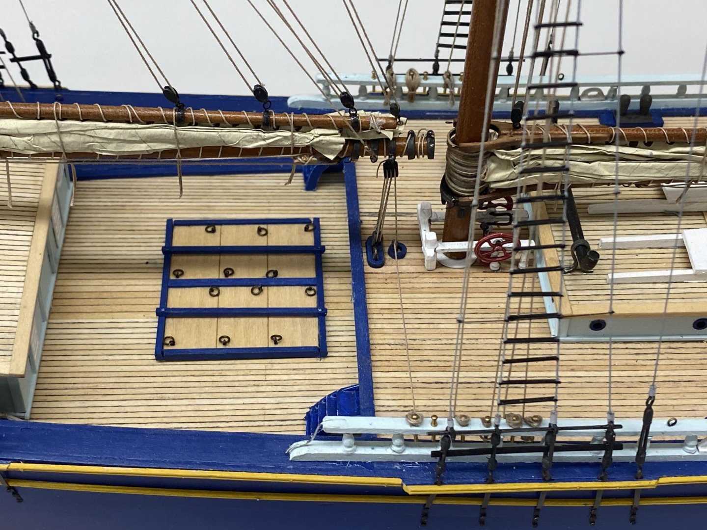
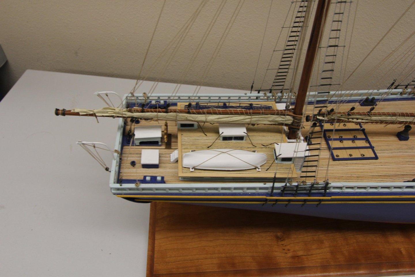
I finally got all the "steps" installed and the anchors attached to the cat heads. The "barky" is just about as done as I am capable of making it. I am going to do a bit of paint touch-up and then declare it "DONE". Here are some "overall" shots of the completed model. I will post some more pictures when the paint touch-up is done, hopefully tomorrow.


- 144 replies
-
- 8
-
-
- charles p notman
- finished
- (and 1 more)
-
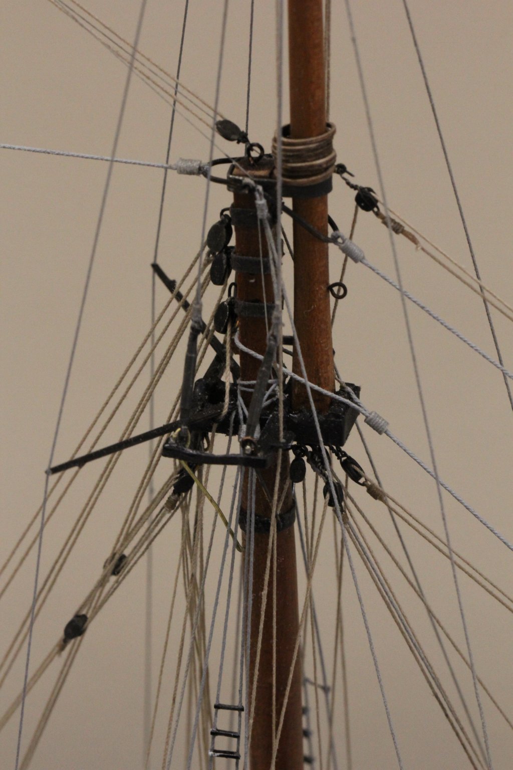
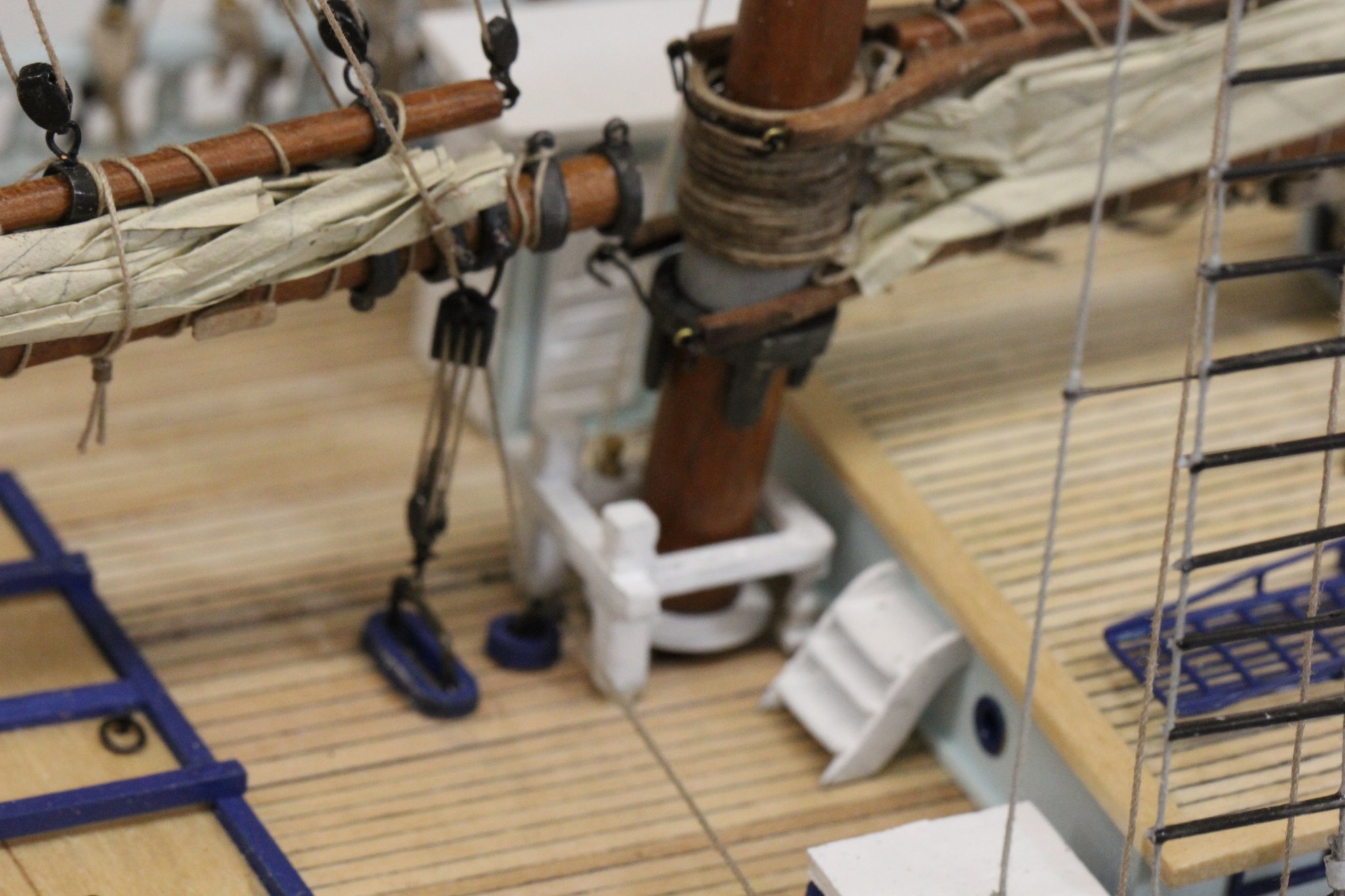
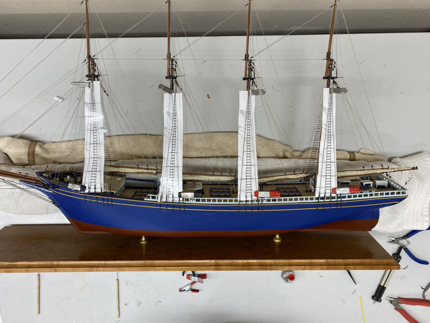
I finished the starboard side. And I have the port side "in position" and am working the wire "ratlines" on each mast before tackling the "steps". To try and get all the "wire ratlines" lined up parallel with the waterline I used the laser level to align the templates as I was clipping them in place. Then I decided to do the wires across each mast rather than one mast at a time. This gives plenty of time for the medium CA to set up on the first mast before I come back to add the next wire. Don't ask me how I came to this realization. So here is the port side "under construction"; the towels are (in theory) protecting the starboard side while I work on the port.

- 144 replies
-
- 2
-
-
- charles p notman
- finished
- (and 1 more)