cdrusn89
-
Posts
1,915 -
Joined
-
Last visited
Content Type
Profiles
Forums
Gallery
Events
Everything posted by cdrusn89
-
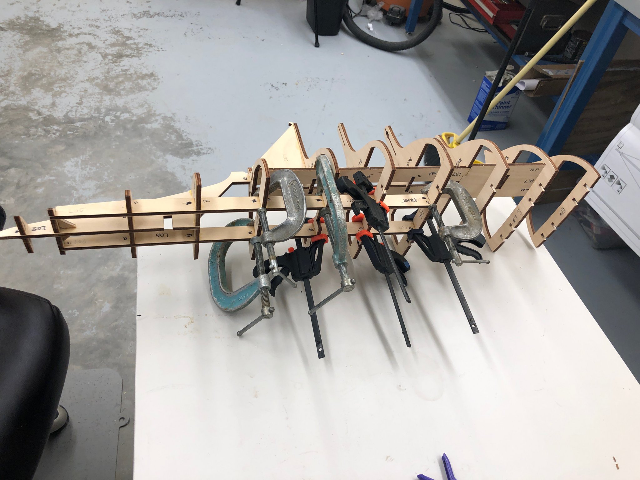
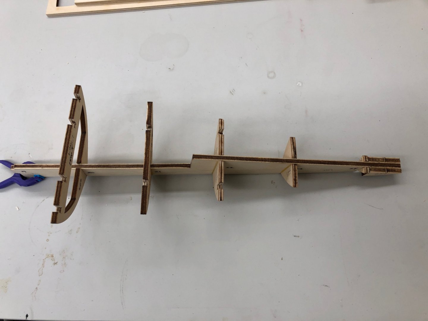
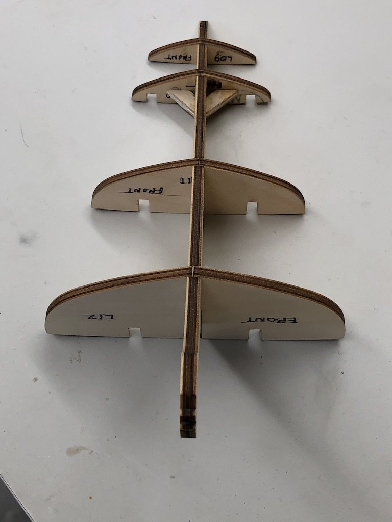
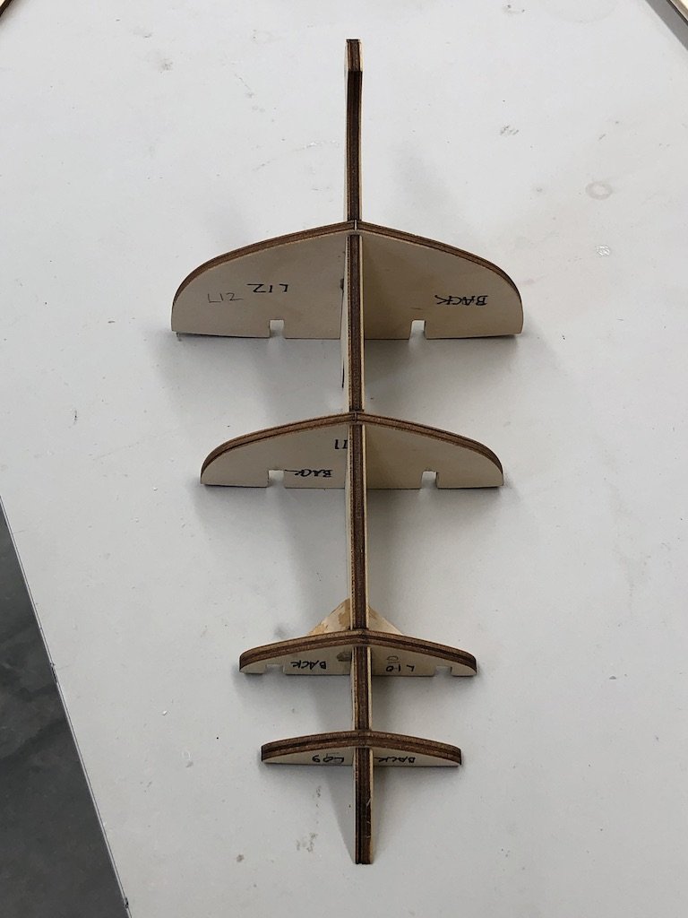
 Thanks Jim I have found two errors in the pictorial instructions (so far). For those who may tackle this kit in the future, In Figure 08 on the first page of the pictorial instructions what is called out as item L.10 should be L.09 (the last bulkhead aft). In Figure 15 on the second page of the pictorial instructions what is called out as L.47 should be L.49 (one of the two reinforcement pieces which fit between the bulkheads). While assembling the the fore, aft and midships sections together used both CA and Titebond glue depending on the circumstances. At some points getting all the grooves and notches lined up and seated home (to hold the correct deck curve) required clamping every intersection between a bulkhead and a longitudinal. When everything was where it was supposed to be I hit every side of every joint with thin CA. When that dried I put a bead of Titebond on each side of each seam. I am n ot sure that will make the joint any stronger but it makes me feel better. Here is a picture of the aft and midships assemblies going together.
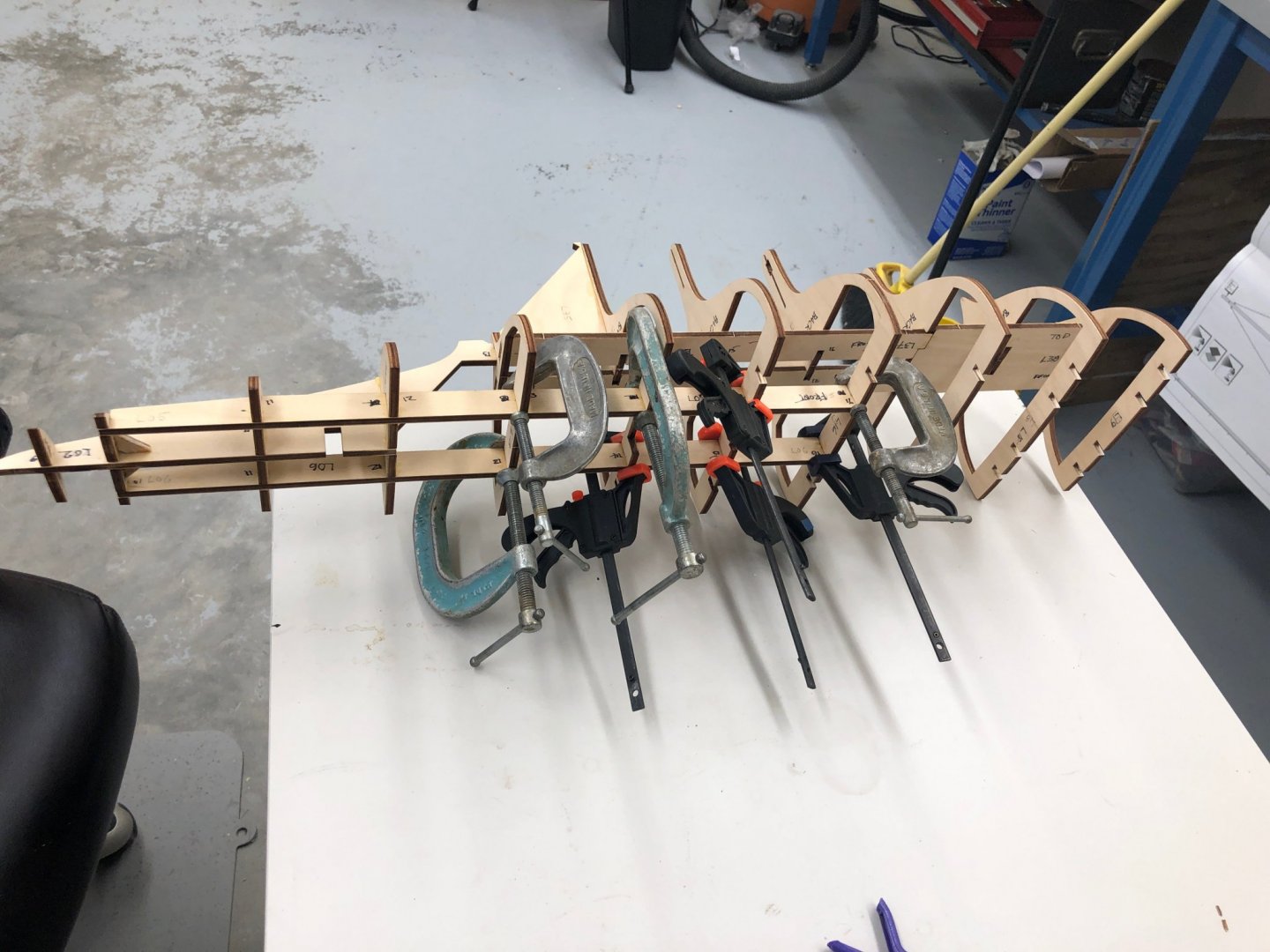
-
Stern section (less the pieces required to form the stern counter - I haven't decided whether to use the pieces supplied (plywood) or the balsa wood I have) completed.Endeavour Build Log photos

-
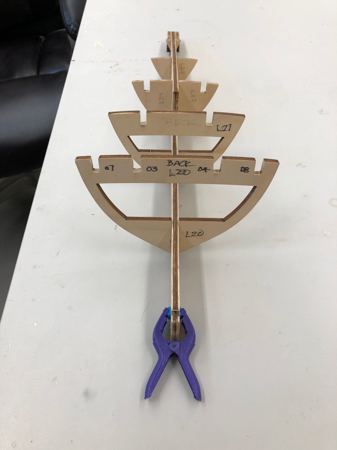
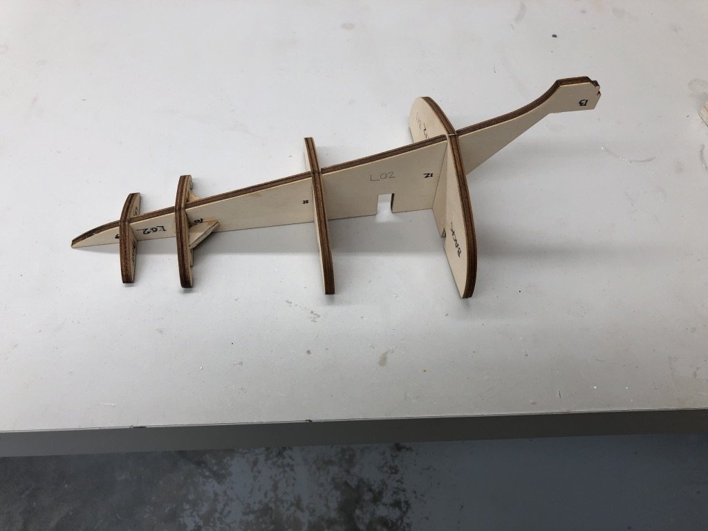
Welcome aboard Yves. I passed by Raleigh on Thursday heading back to Florida to prepare for Hurricane Dorian. Now it will be Monday before anything significant happens here outsie Orlando. Oh well, better prepared than not. So I got the stern section together. I had to add the two support members to get bulkhead 10 square with the longitudinal. I had it clamped square but it really looked out of square when I pulled the clamp off. Working on the bow and center, one bulkhead at a time.
-
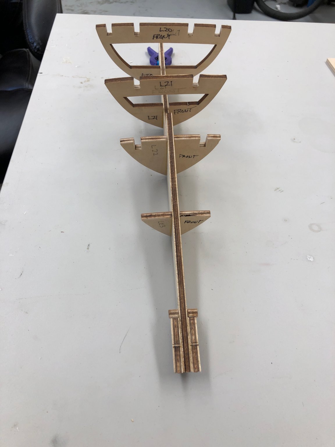
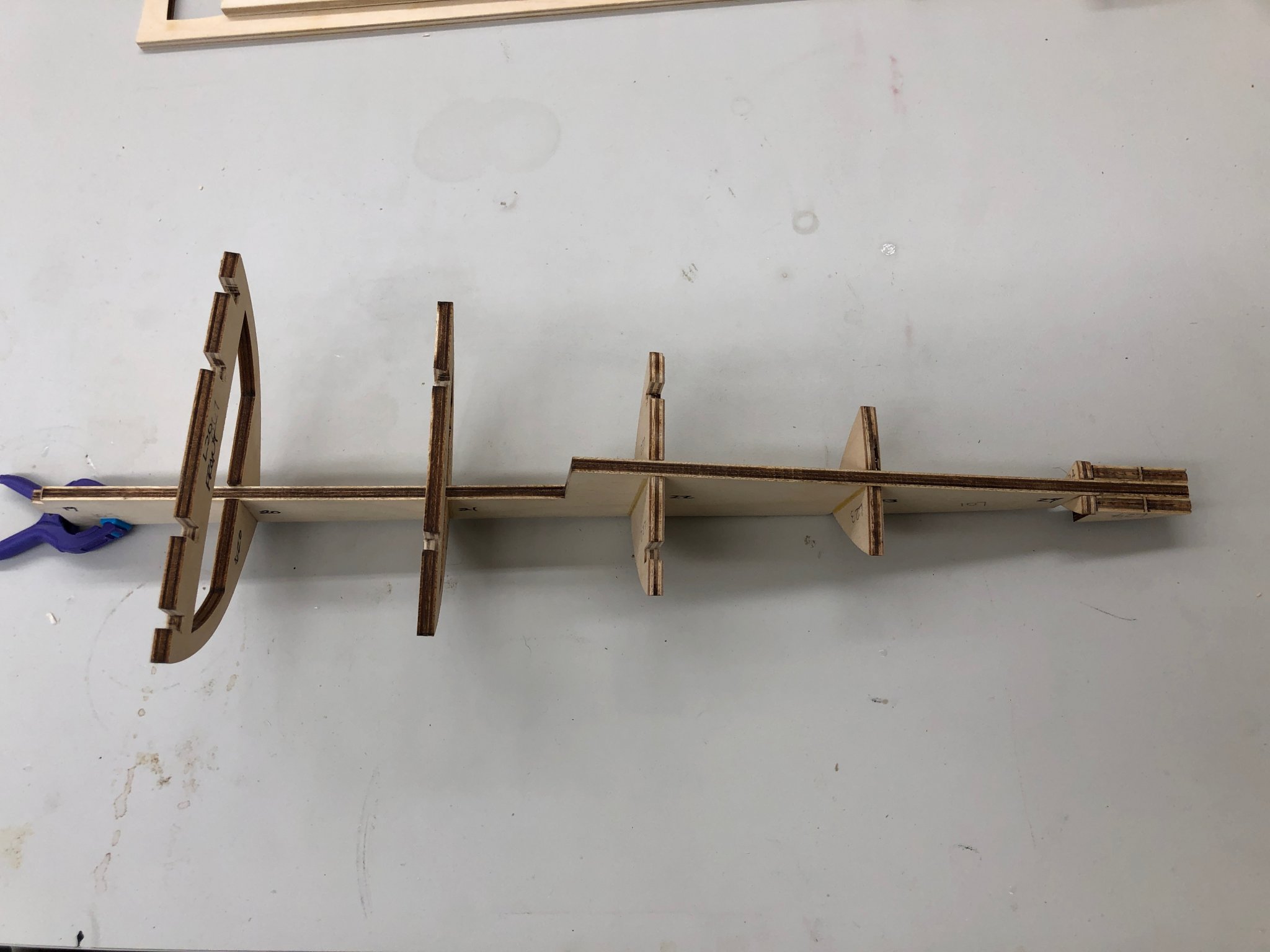
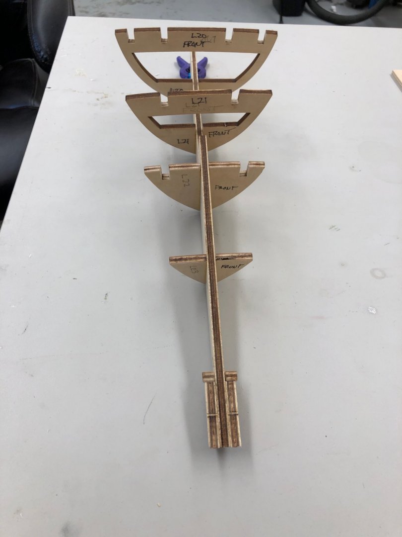
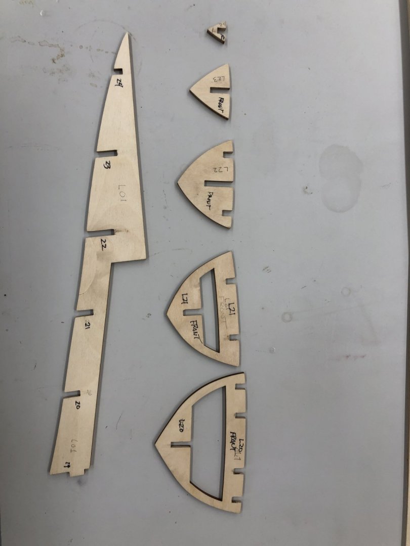
So I labeled all the pieces (then relabeled them to identify front and back and which end goes forward on the longitudinal pieces. Here are the pieces for the bow section ready for assembly. I plan to put the sections together (after carefully sanding/filing out the slots and dry fitting everything) in several stages using my set of metal "squares" to keep the "frames" square to the longitudinal pieces.
-
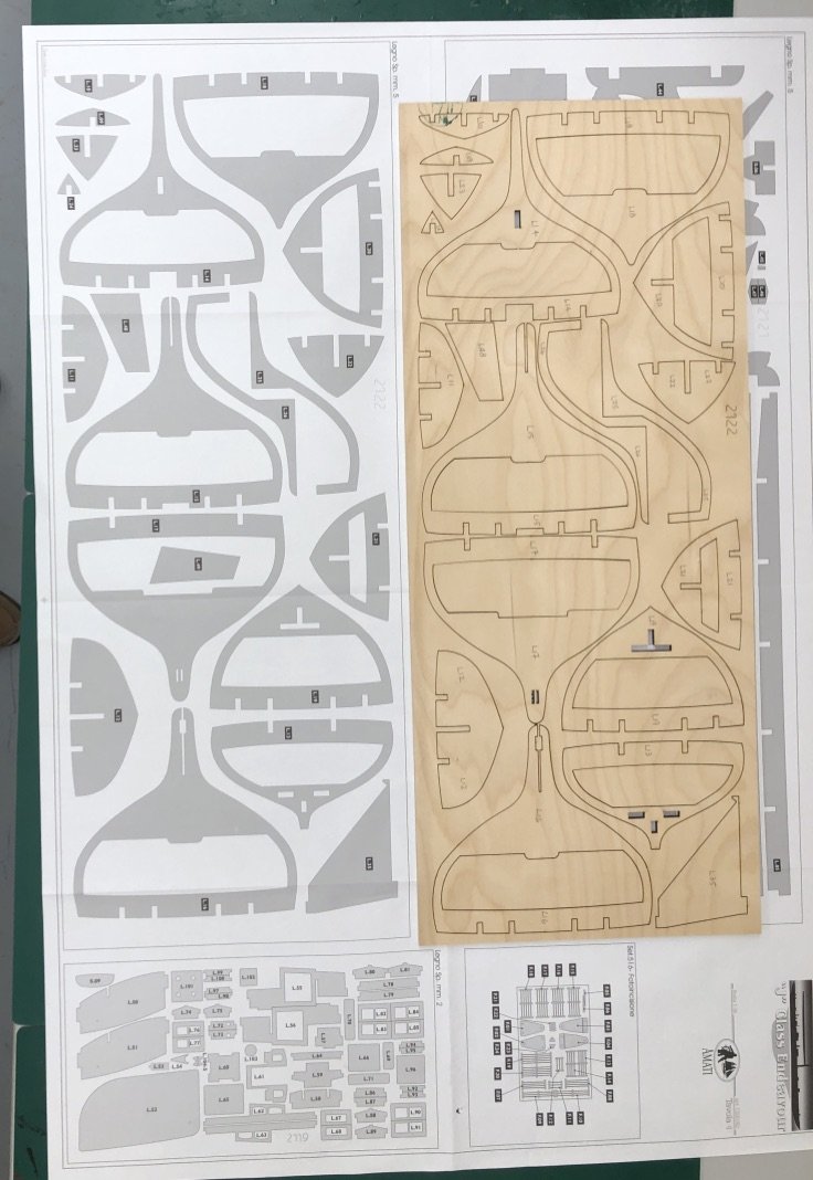
First job is to mark all the pieces according to the full size plans provided and get all the other pieces organized (or at out of the kit box).
-
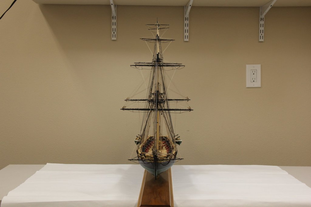
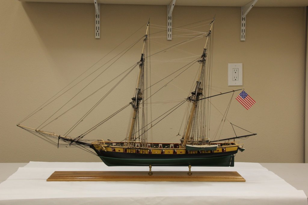
After completing (except getting it in the case) the US Brig Niagara I decided I was "done" with square riggers (and square rigging) for awhile. I had intended to build this one to go over the fireplace in my house in Virginia (it would have replaced a "cheap" model of the 1934 Endeavour that was purchased from a model home) that is about the same size. But that house is gone and finding a home for this one will be a challenge but I will press on anyway. So here is the box on the relocated (from Niagara days) workbench

-
Thanks Ric - on to the Endeavour
-
Thanks everyone - I know that reading through the build logs of others was a great help to me. Hopefully others will find some help (and maybe inspiration) from mine. On to Endeavour! But first a two week road trip to see the "real" Niagara (and the other tall ships touring the Great Lakes this summer).
- 367 replies
-
- 2
-

-
- model shipways
- niagara
- (and 1 more)
-
Thanks guys - here are some more pictures. At one point I had intended on moving next to the US Brig Syren but I think I am done with square rigging for awhile so my next build is Endeavour (the 1/35 scale one) by Amati. Lots of hull and only a little rigging. Also a chance to put my girlfriend the quilter to work making the sails. Getting sails that do not look terribly out of scale should be easier at 1/35.


- 367 replies
-
- 5
-
-
- model shipways
- niagara
- (and 1 more)
-
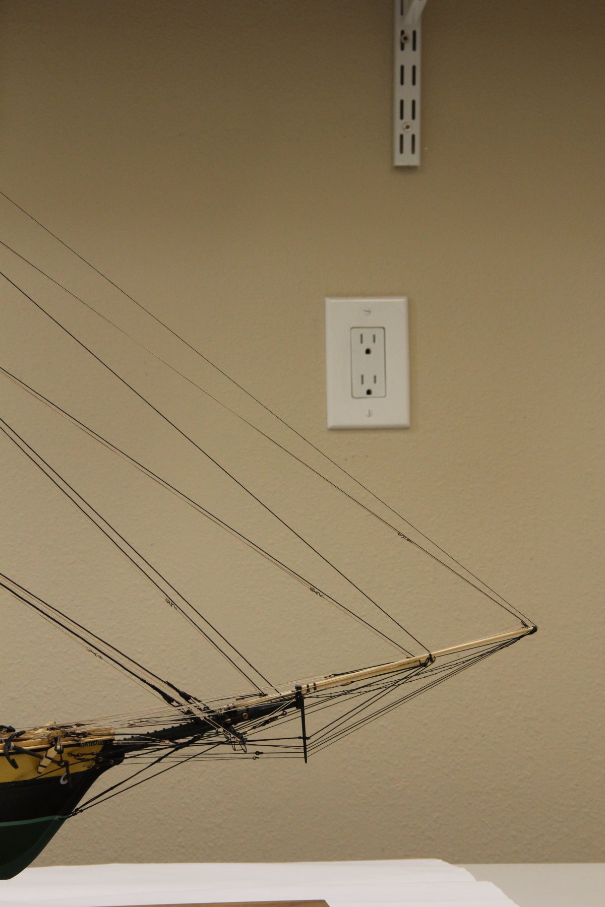
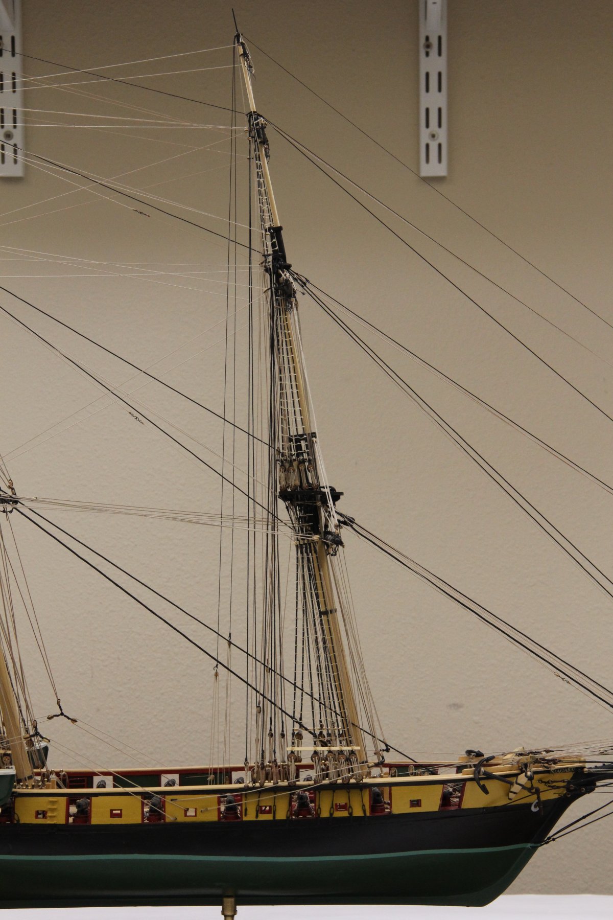
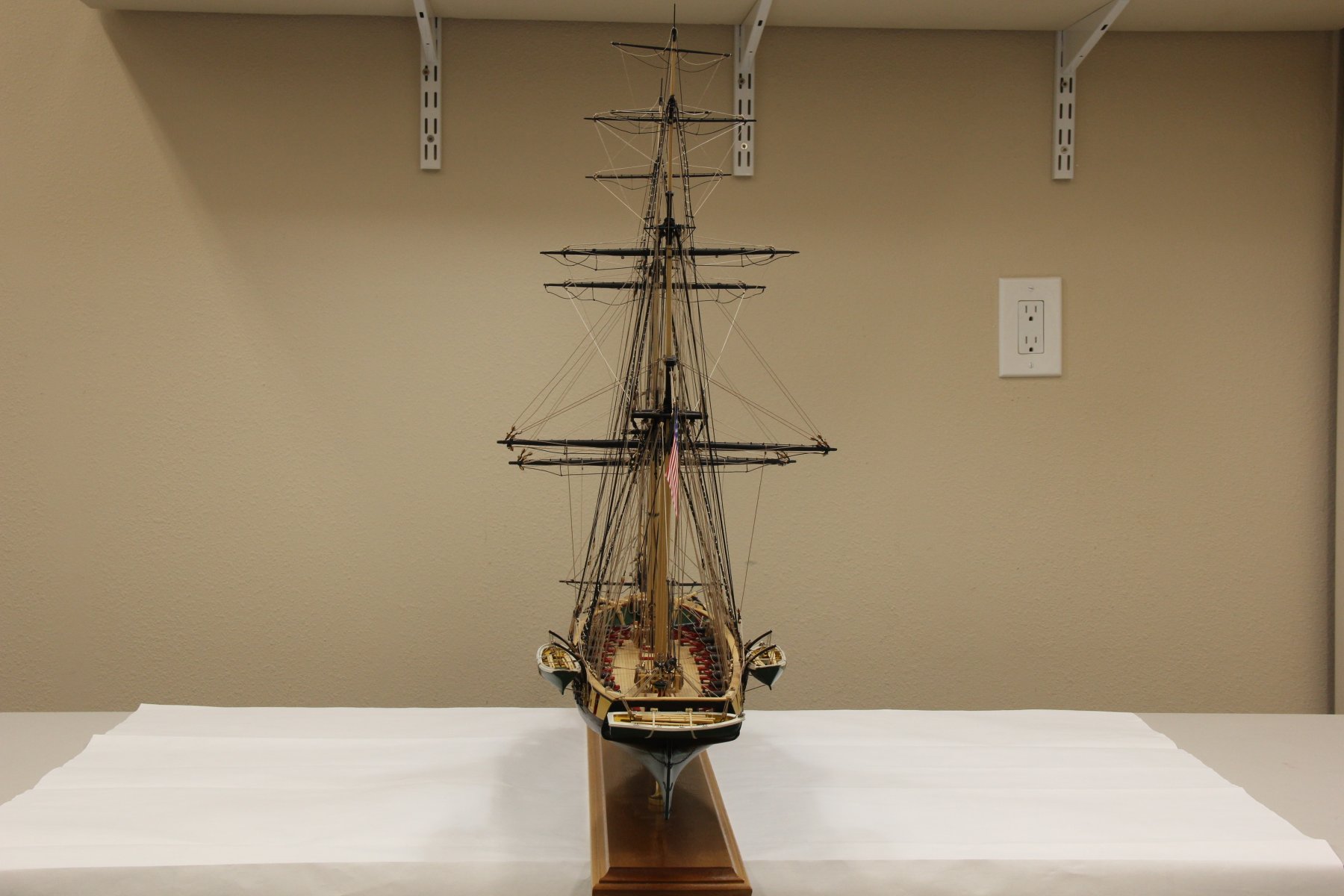
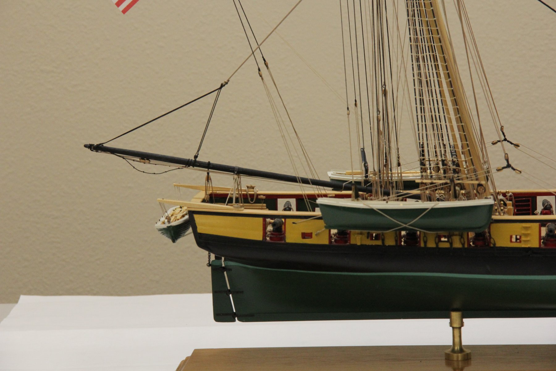
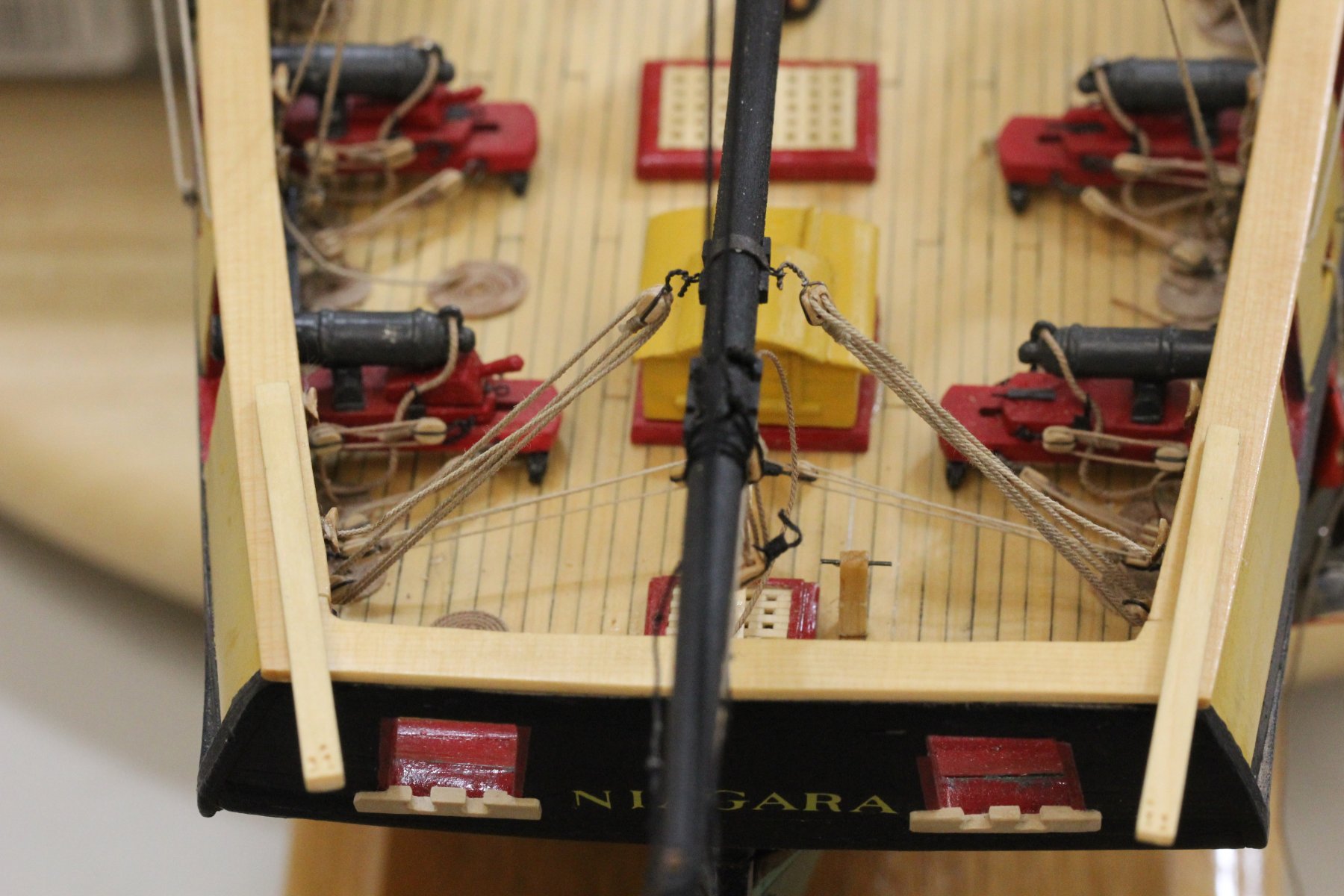
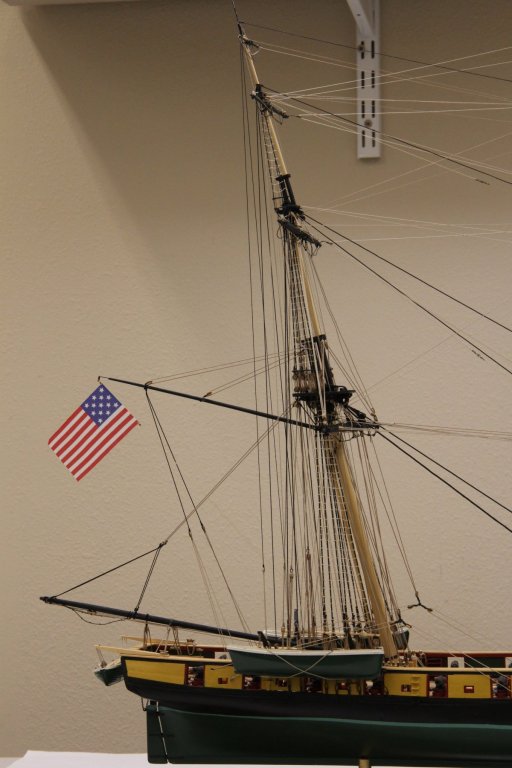
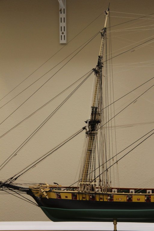
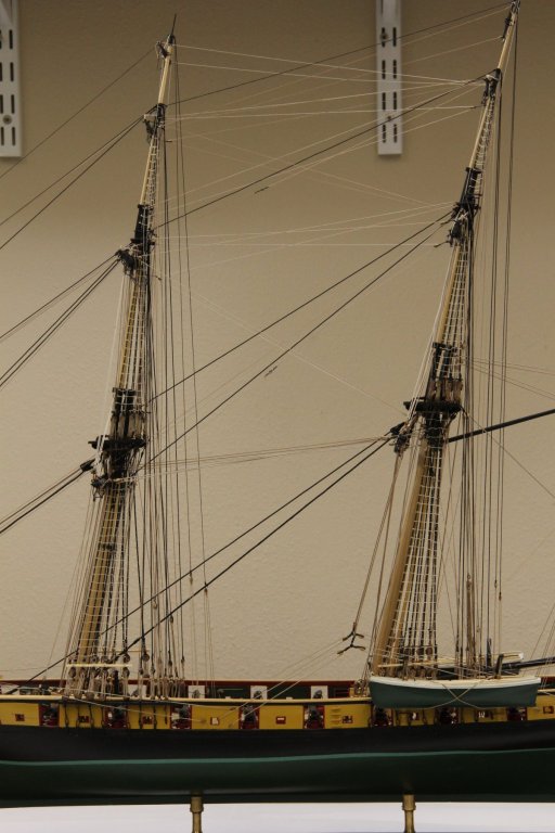
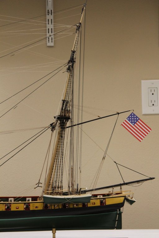
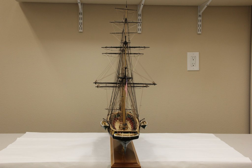
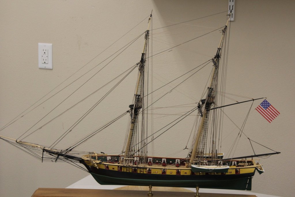
My Niagara is FINISHED! And before anyone points it out; i know that is not the correct flag (should have 15 stars and stripes) but us poor backwoods types, stuck in the wilds of western Pennsylvania never managed to get the correct flag from those responsible for such things back at the "seat of Government" so we used what we had - like many items used in the actual construction of Niagara (and Lawrence) - they used what they had. In all seriousness this is my first try at rigging a flag so I took the cowards way out and bought one that was as close as the correct one as I could find. I did try the Chuck Passaro method explained in the Cheerful monograph but could not get a satisfactory result - I probably do not have the "correct" tissue paper - I tried three different types and then resorted to a commercial one from Model Expo. Here are some pictures of Niagara before she goes in the case which I don't have just yet. I will get some more pictures after I clean up the shop and find a more presentable background (assuming there is one).

- 367 replies
-
- 6
-
-
- model shipways
- niagara
- (and 1 more)
-
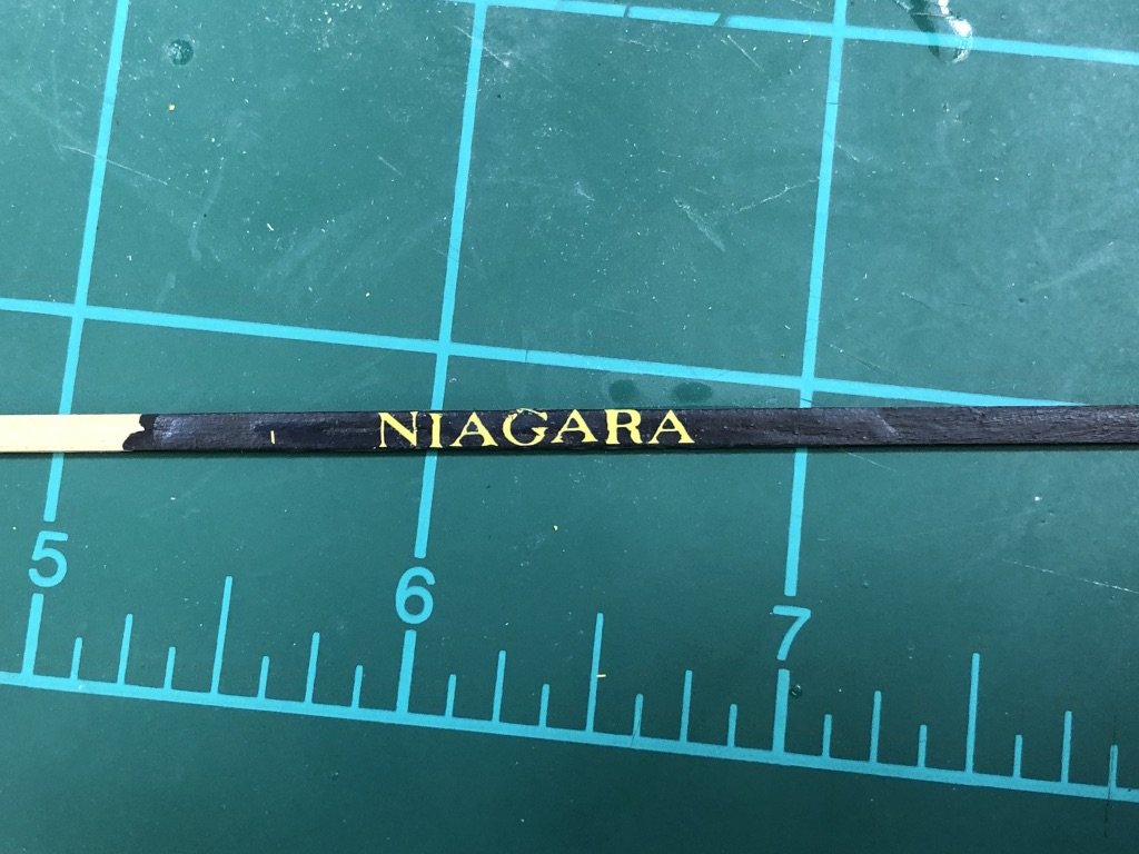
Thanks Kevin - she is almost "DONE". Got one of the forward name boards completed. Hopefully I get the next one without errors as my dry transfer sheet only has three more "A's" and I need every one of them. Messed up the "G" some but I don't think it will be too noticeable among all the rigging up on the bow. A word of caution to those using the dry transfer letters - be careful how you hold the letter sheet down. On more than one occasion I transferred all or part of a letter other than the one I was working on to an area where I had already transferred one. I does not take as much effort as you might think to get a letter transferred.
-
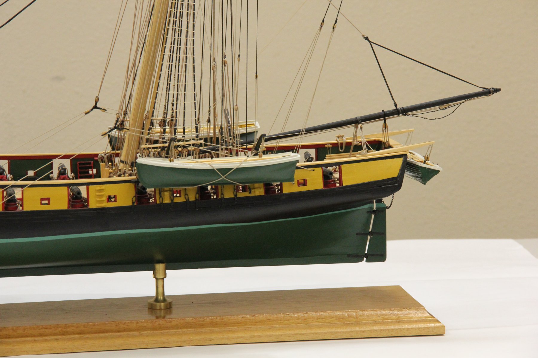
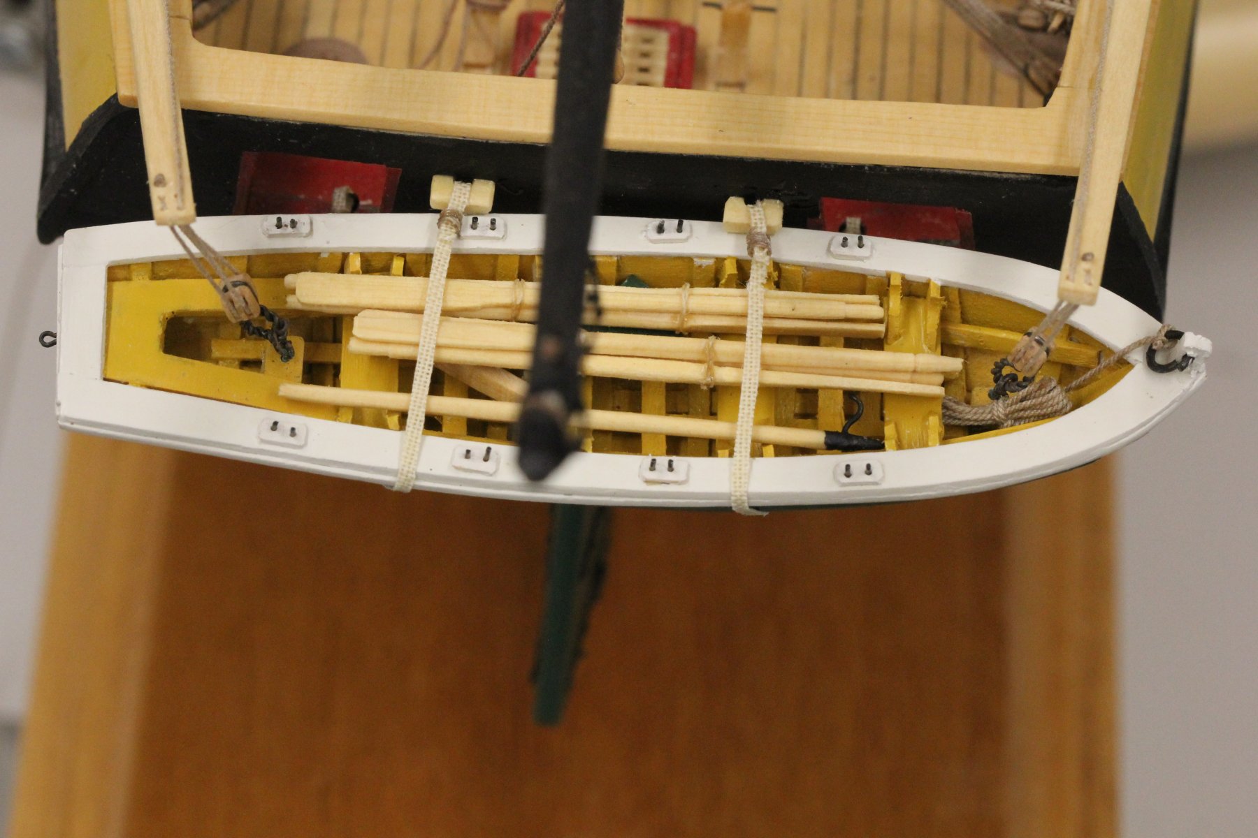
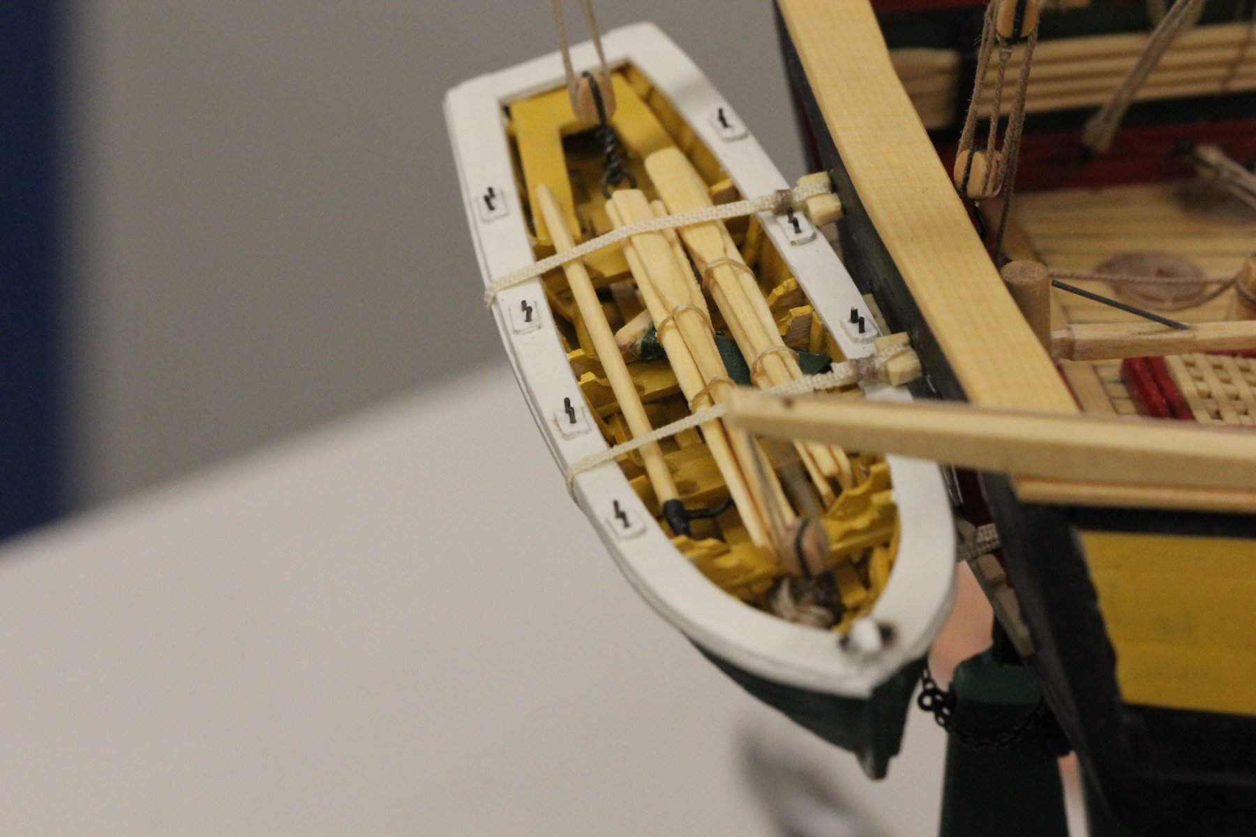
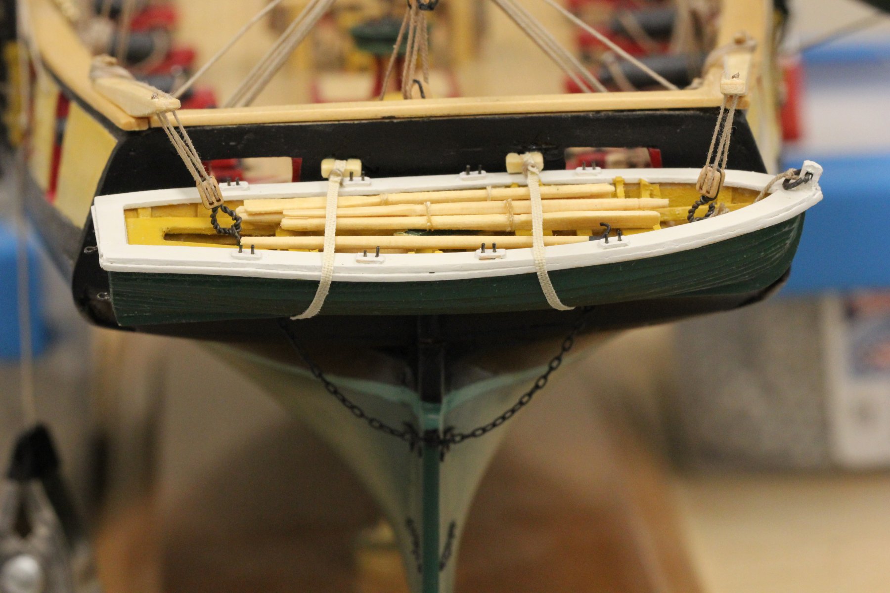
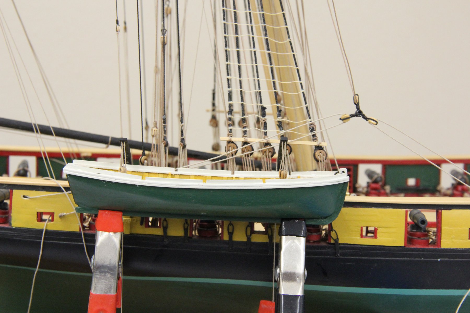
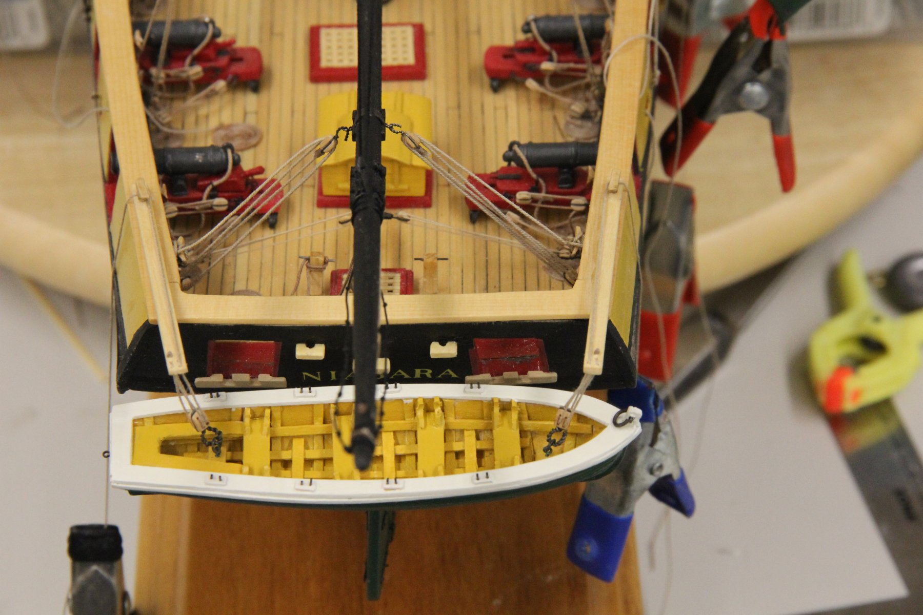
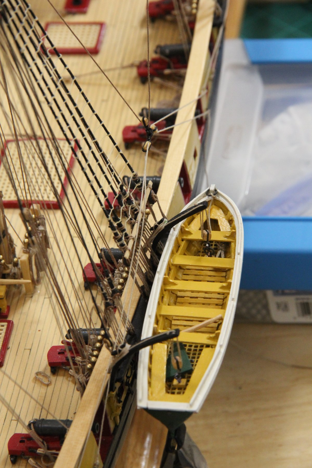
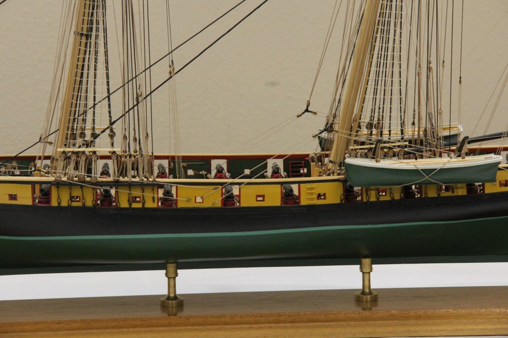
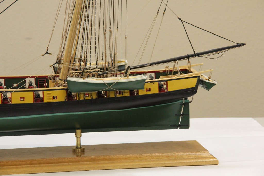
The Stern Yawl is "aboard". Working the port side cutter now. Used a strip of thin material from my girlfriends store of quilting material for the straps. Coated with 50/50 glue/water then used her cutter to cut narrow strip. Probably a little wider than the 3/64s called for in the plans, more like 1/16 but it does not look terribly out of scale, at least to me. Not that with the Stern Yawl in place all that work getting the name on the stern is pretty much gone now. You have to look really hard to see the name.


- 367 replies
-
- 4
-
-
- model shipways
- niagara
- (and 1 more)
-
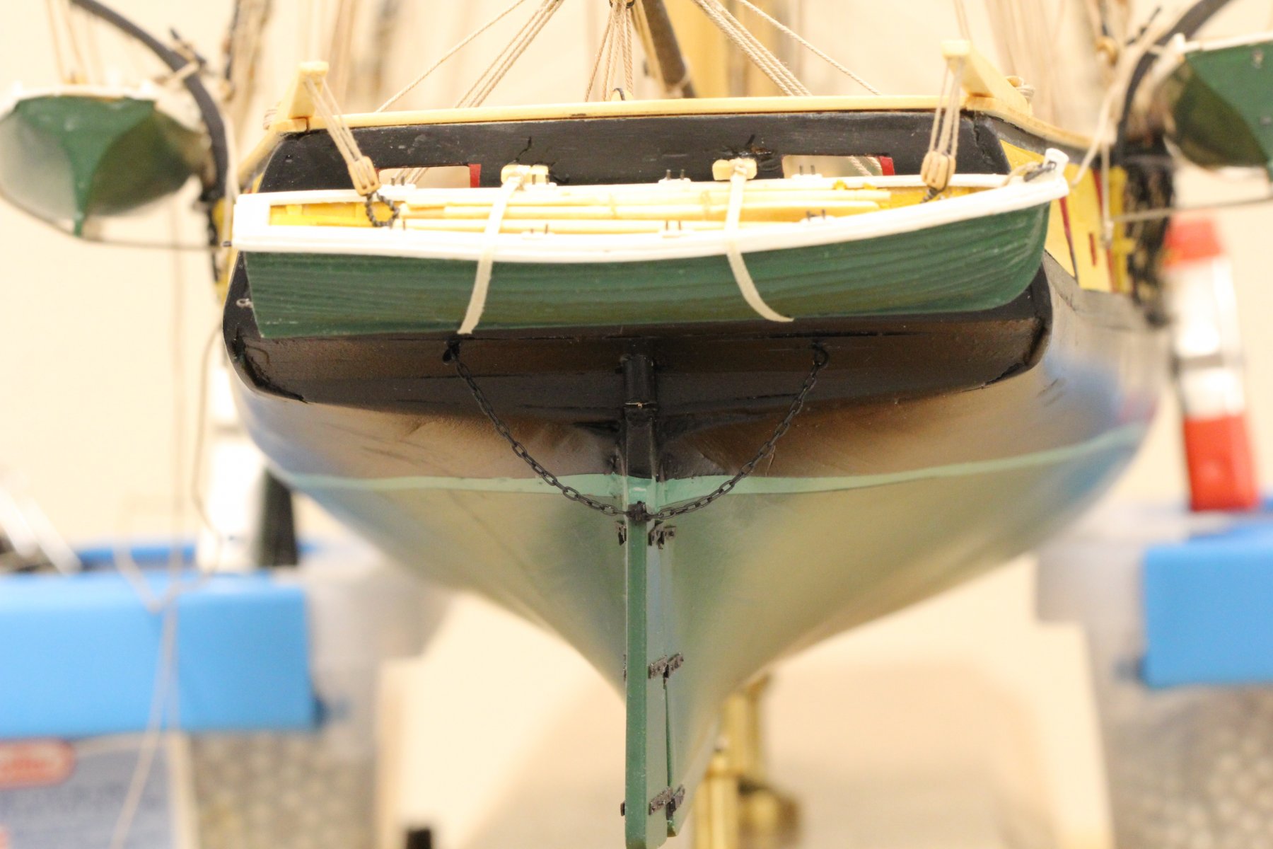
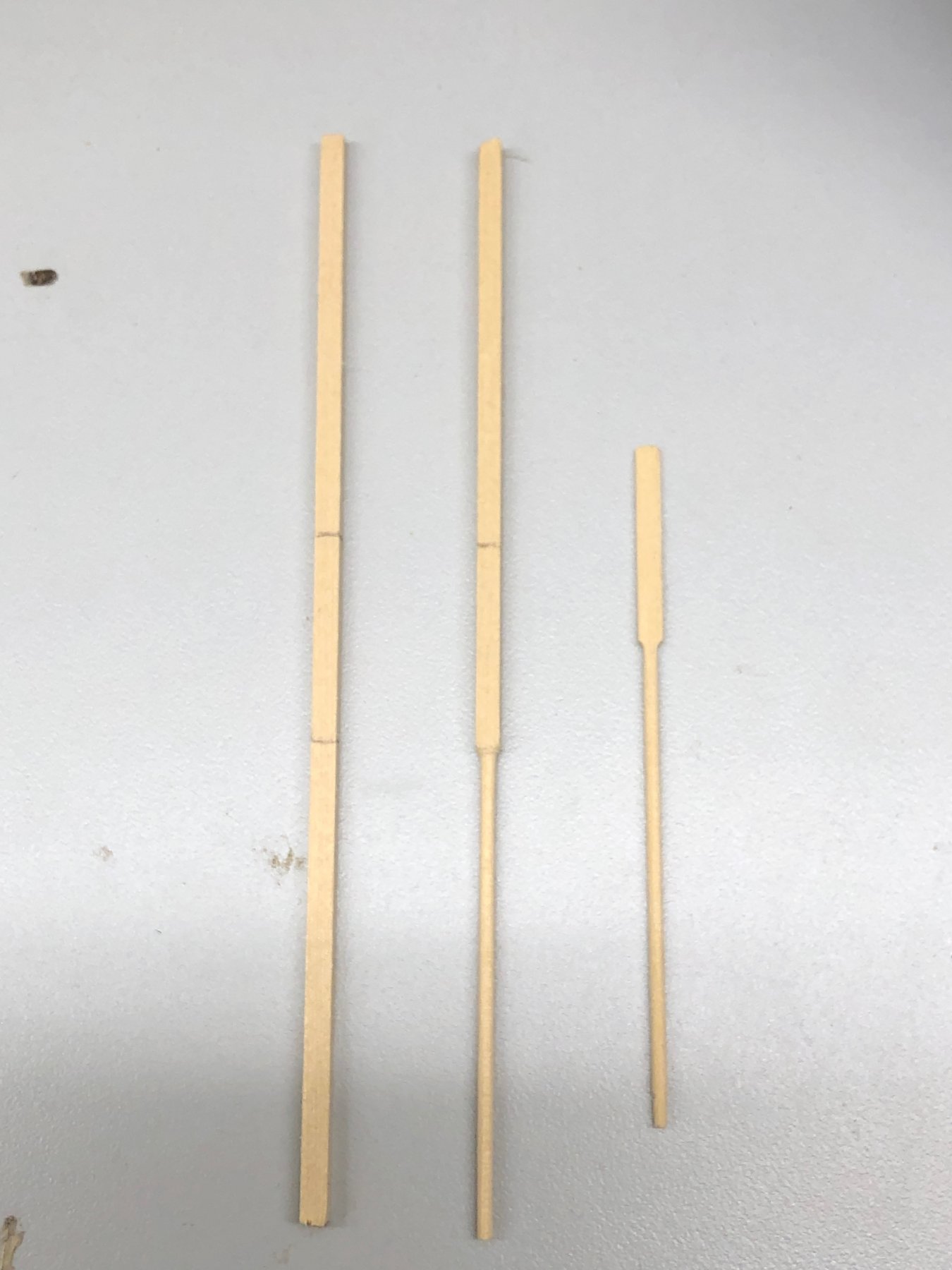
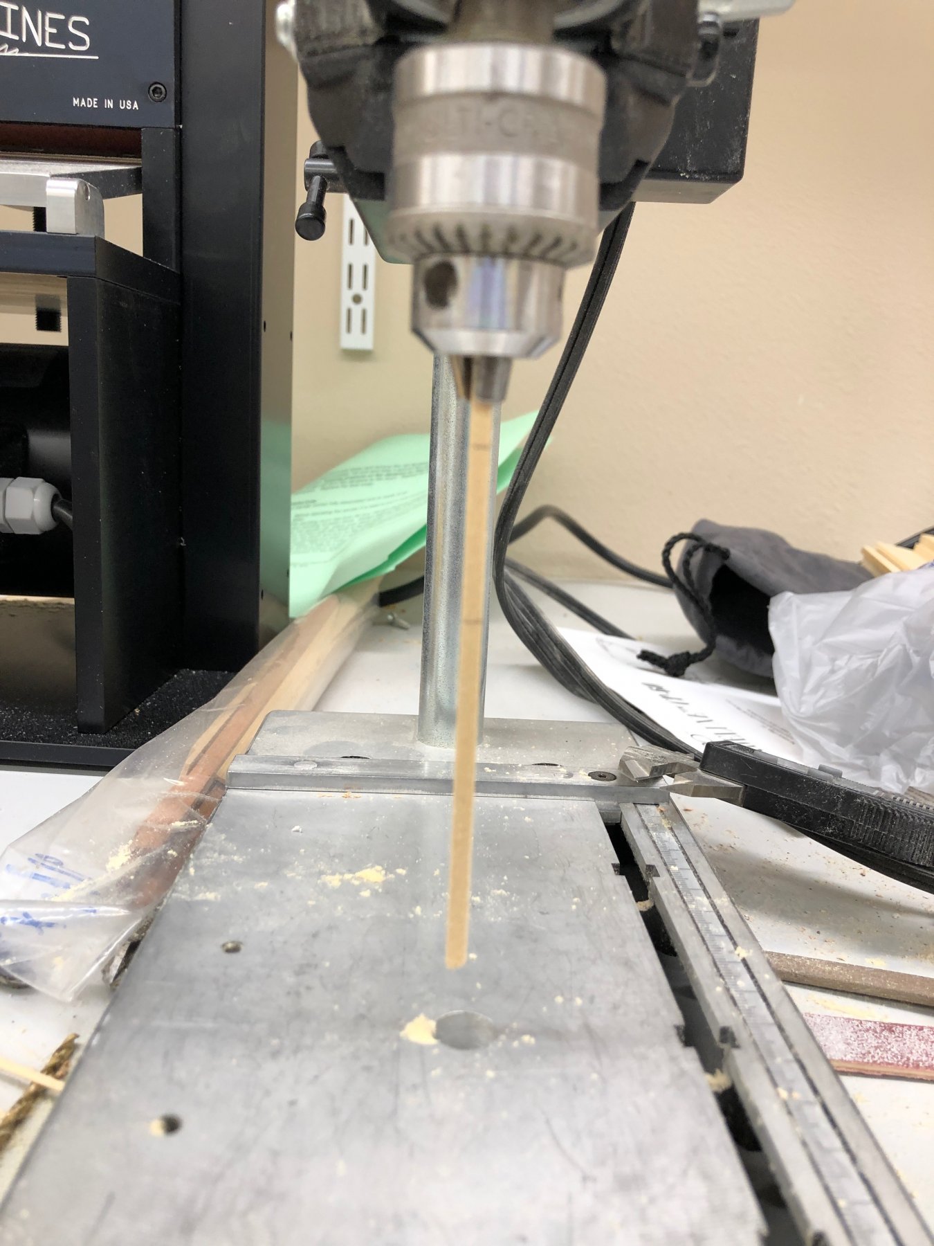
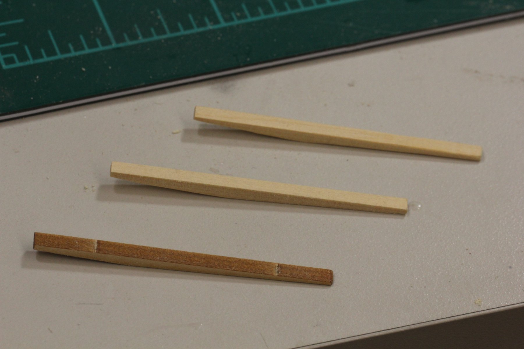
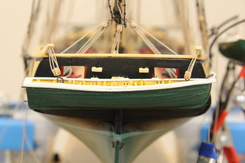
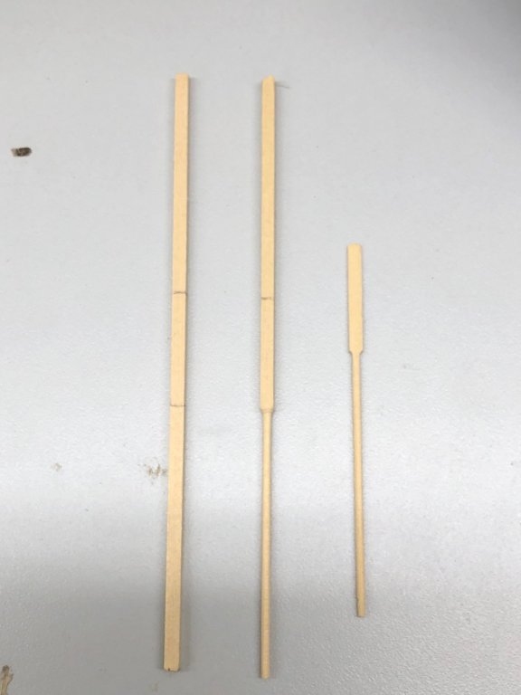
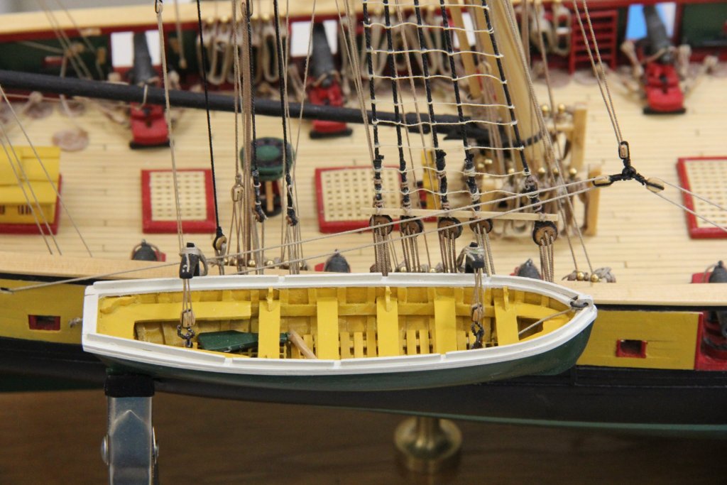
Thanks Phil. Hopefully it will only be a few more days. So, after two broken davits I finally got the stbd cutter hung on the davits. If I had it to do again I would probably put some weights in the bottom under the floor boards. As. it stands they are very sensitive to exactly where the rings are located and how the hooks on the falls contact the rings. If I left off the gripes this one would list to port about 25 degrees. I used some clamps attached to the boat keel to keep it level for the pictures. Speaking of gripes, the plans say they are 3/64" canvas straps but I am n ot sure how I would model that. I am no good with cloth so my intent is to use .025 Syren tan line instead. After that experience the stern yawl went much smoother. I would recommend that the holes in the davit ends to simulate the sheaves be as large as is reasonable (I used a #70 drill) to make adjusting the length of the fall easier. I also used .012 line instead of the .018 (which I would normally have used in place of the .016 called for in the plans). So here are pictures of the two boats hanging in their davits. So I have the boats, what about boat equipment. I have the rudders stored in the boat, a painter line attached to the ring in the "nose" but still need oars. I have some Bluejacket, Britannia metal oars that are the right length for the stern yawl but nothing for the cutters. Wanting to stay with my choice of yellow cedar for the bright work I used 3/32 x 3/32 square stock that I had left over from something to fashion oars for the cutter. Here is a picture of the blank, the shaped piece and the final product - before flat clear finish. I turned to square stock round on my poor mans lathe. I took about 8 minutes to turn the handle from 3/32 square to 1/16 round. And I only broke every third one so 8 minutes time 12 oars + 4 "extras" equals a little over two hours. Seems like a lot of work for a few "accessories".


- 367 replies
-
- 5
-
-
- model shipways
- niagara
- (and 1 more)
-
Thanks Tom - not done yet but getting real close. I'll have to figure out how to edit the build log title to get "Finished" included.
- 367 replies
-
- 2
-
-
- model shipways
- niagara
- (and 1 more)
-
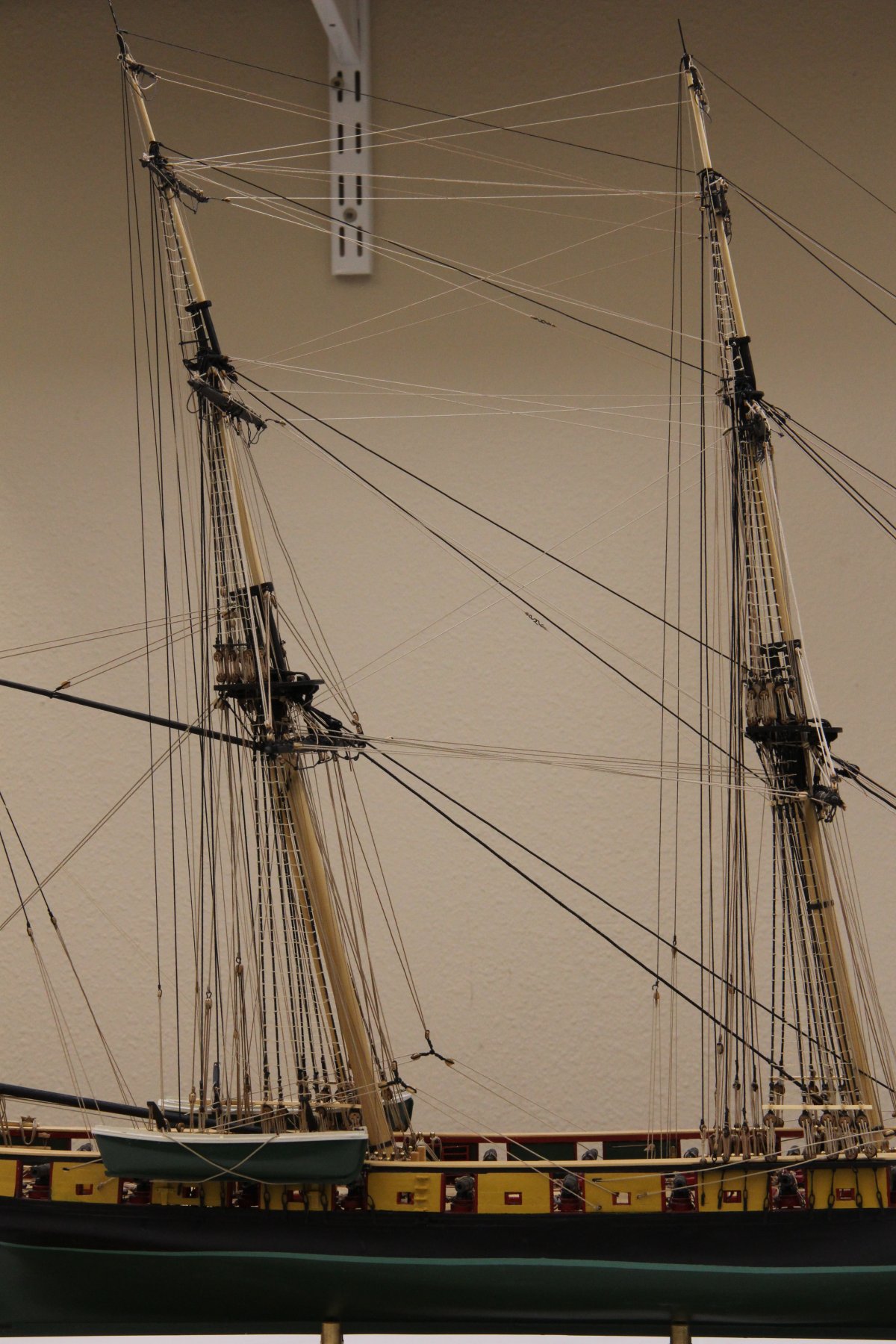
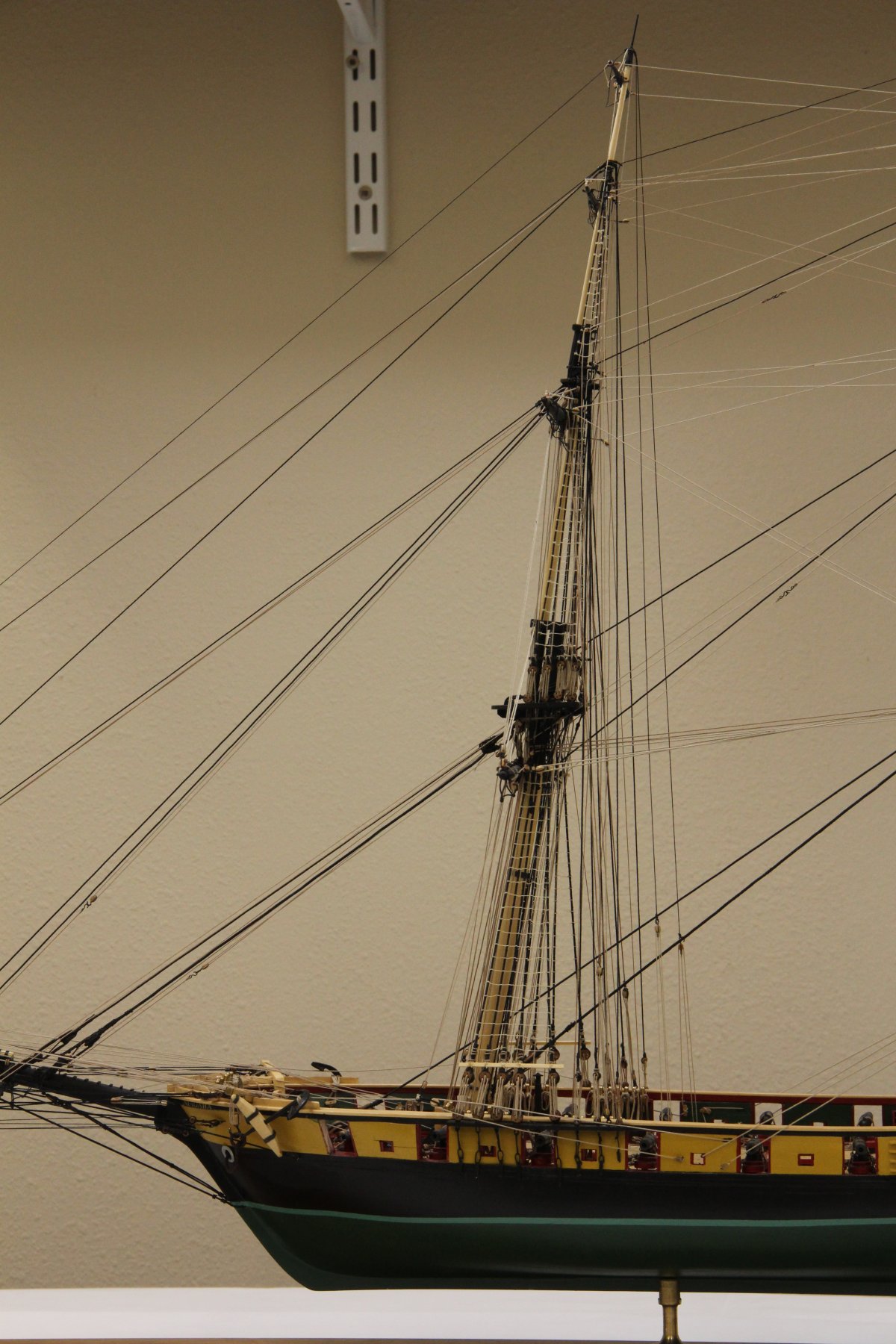
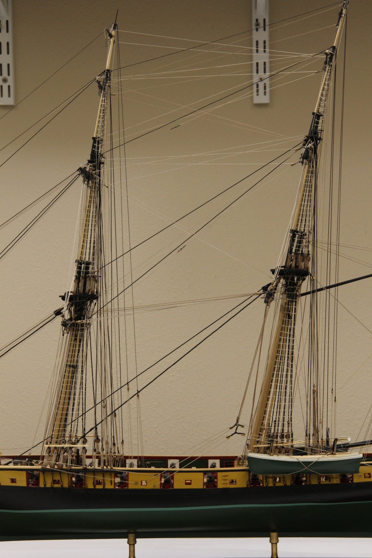
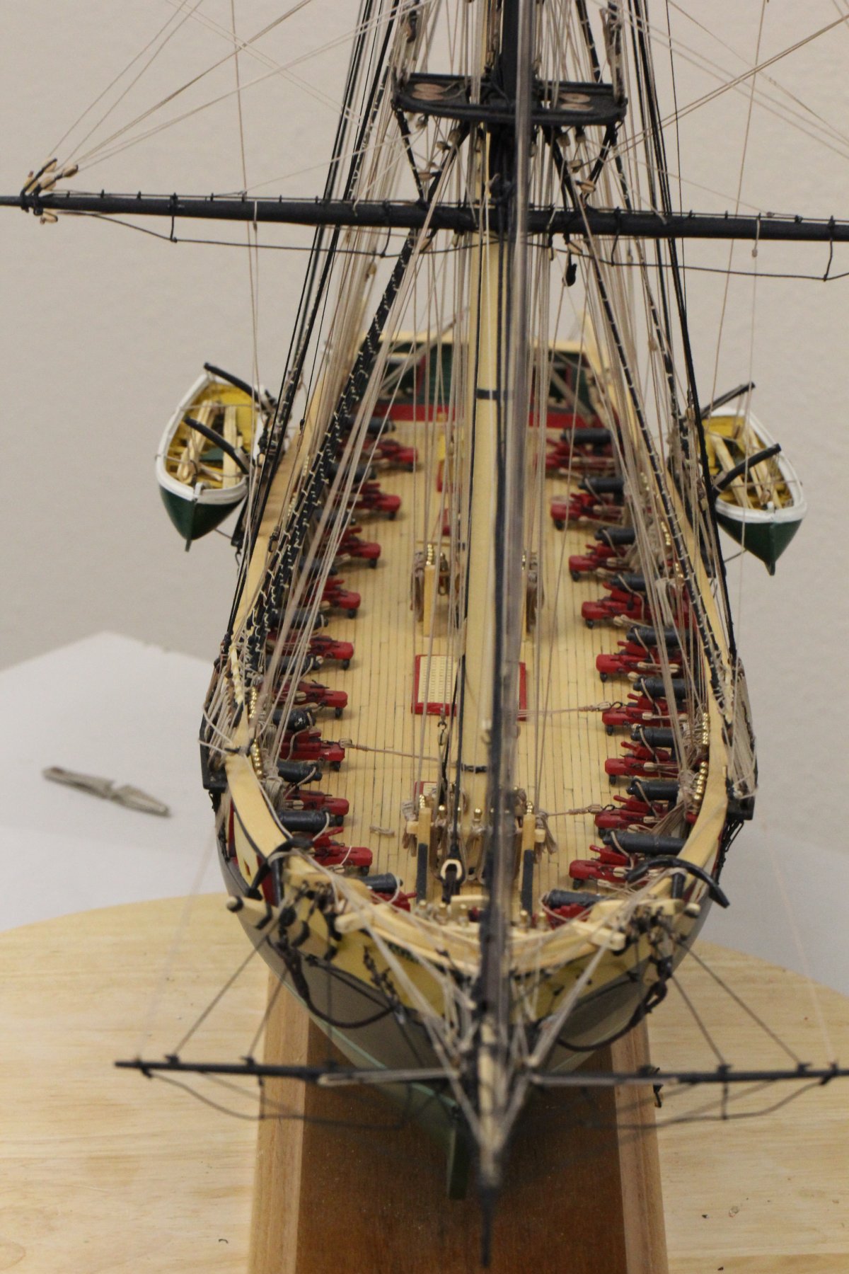
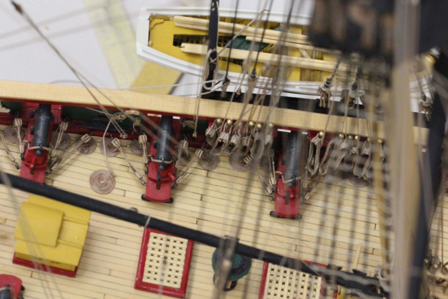
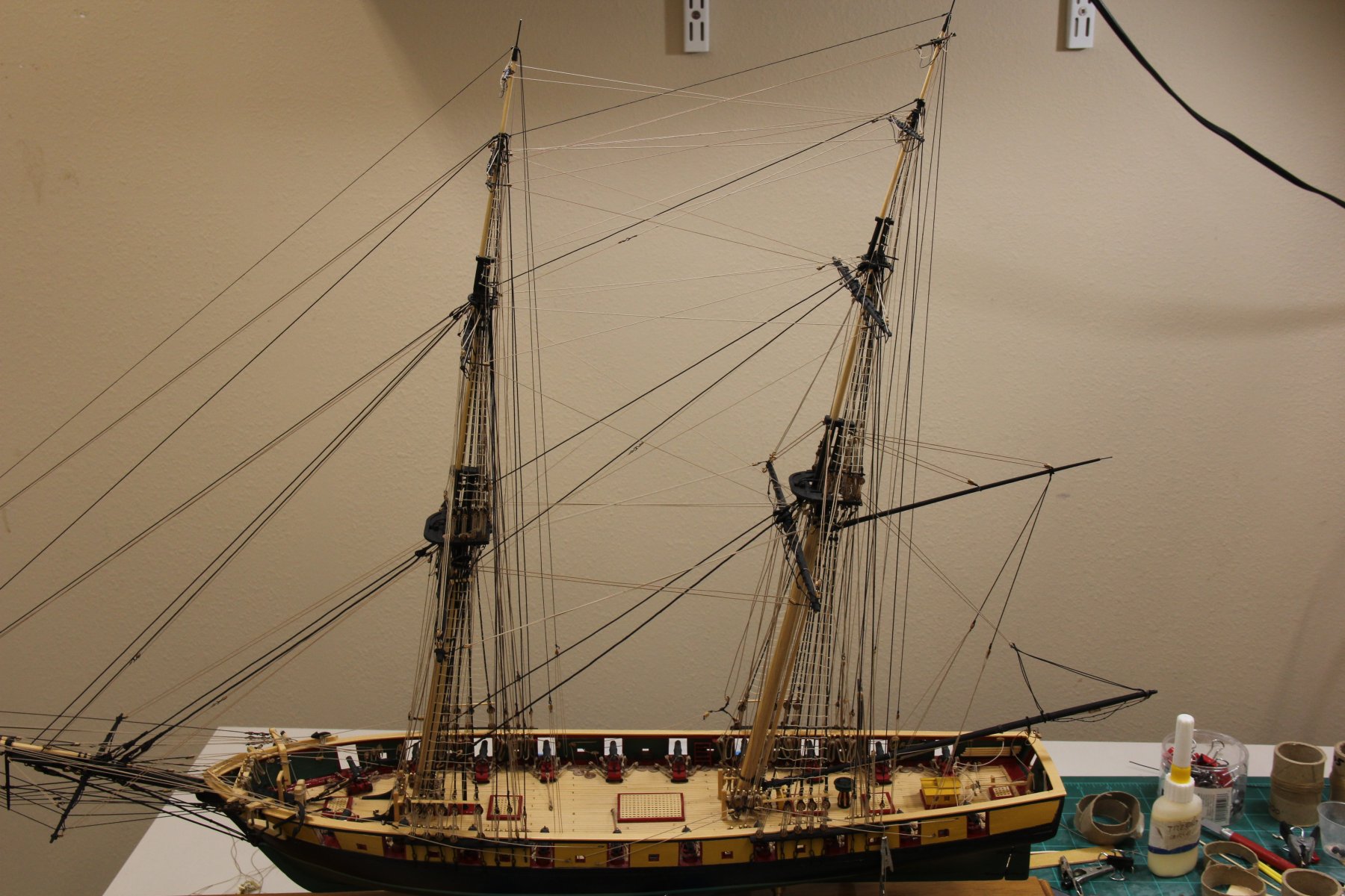
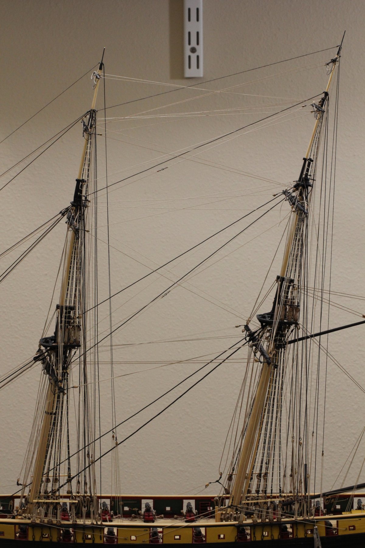
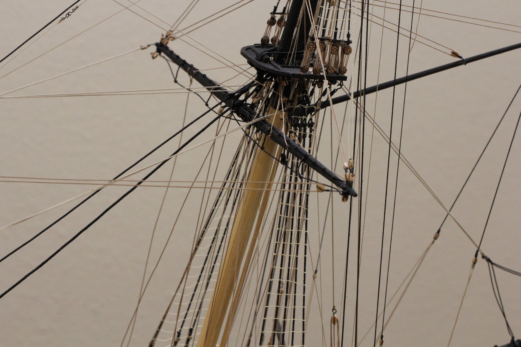
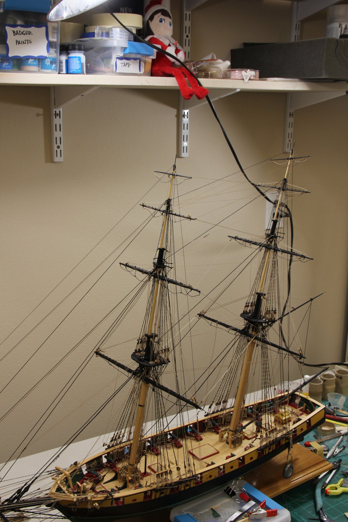
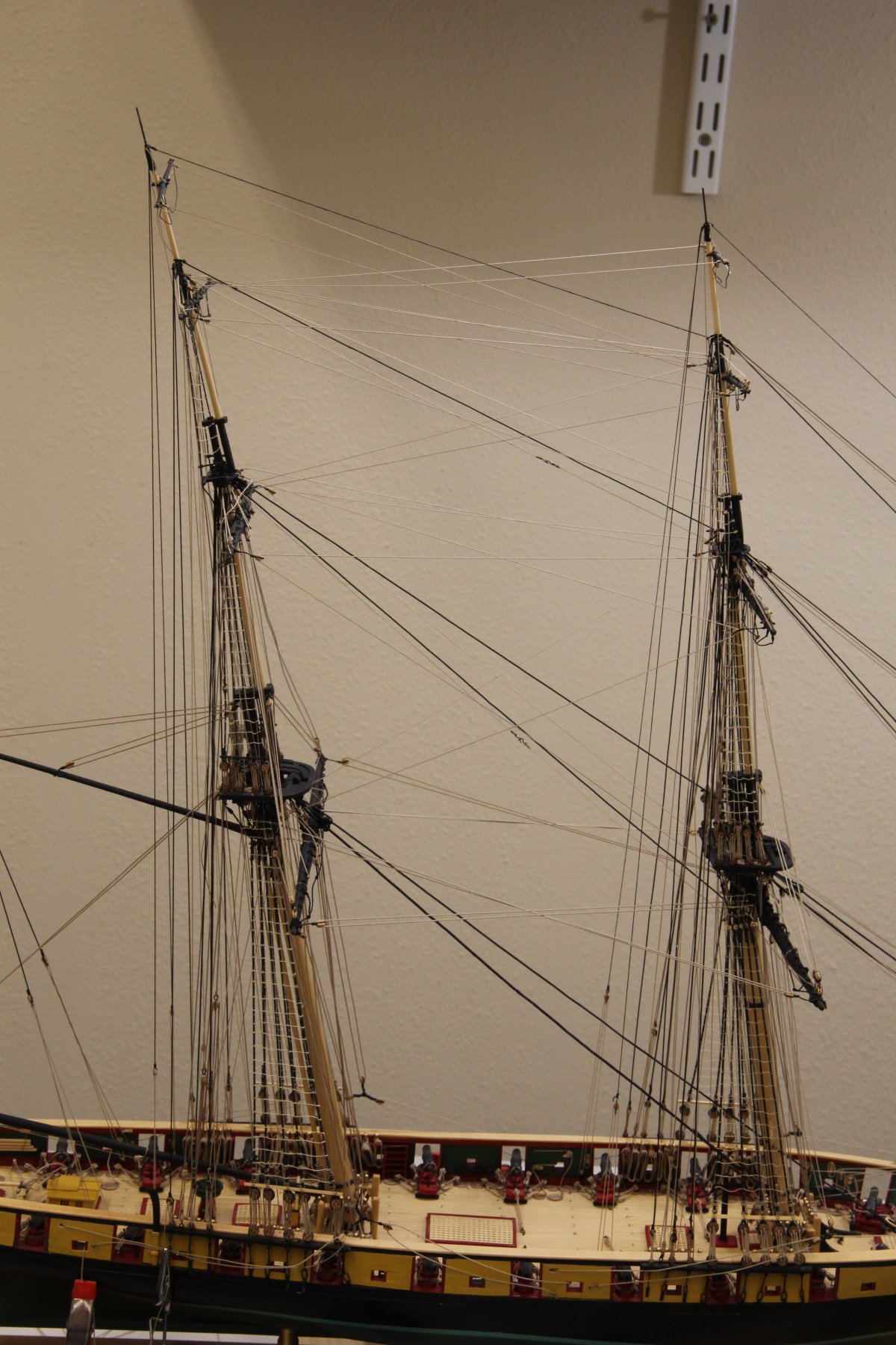
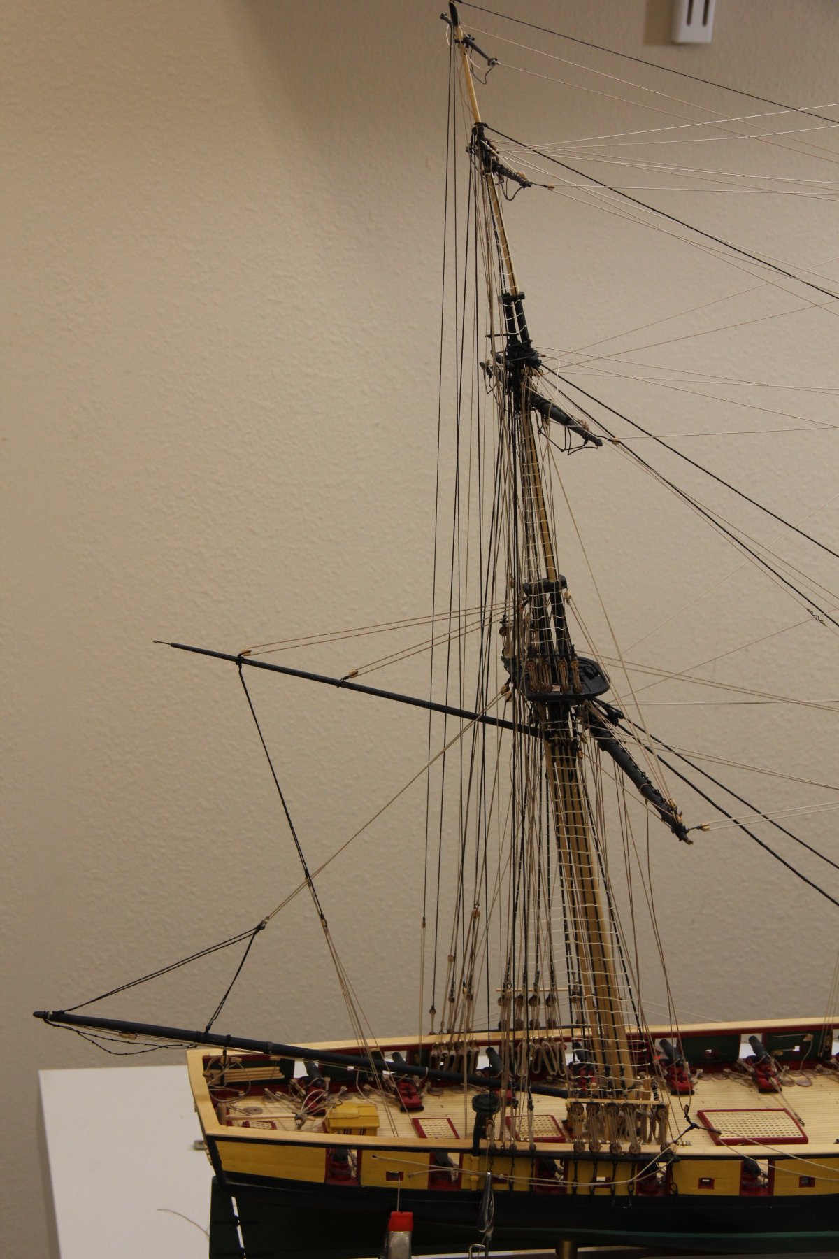
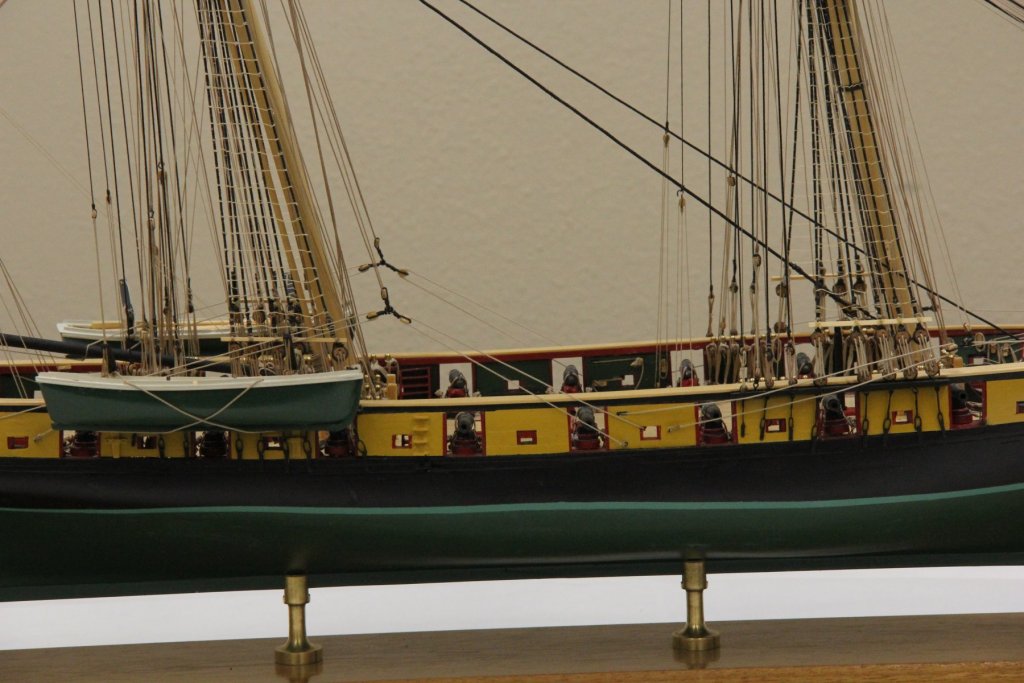
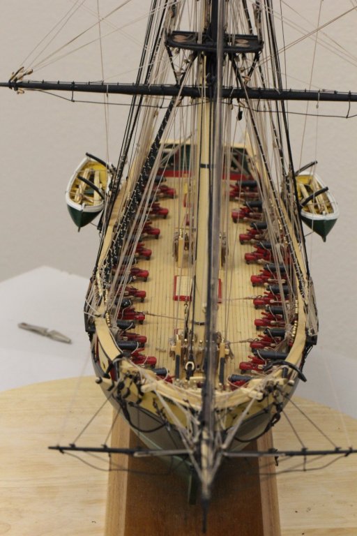
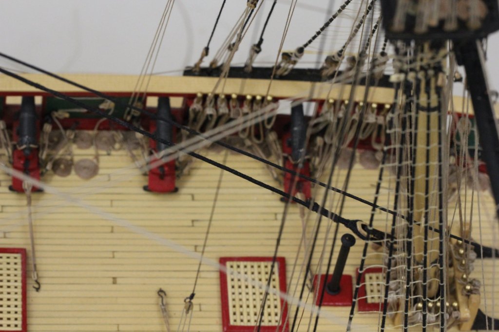
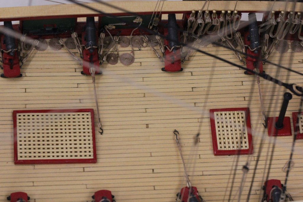
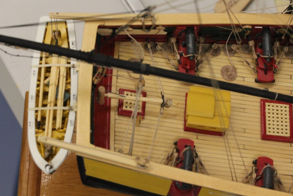
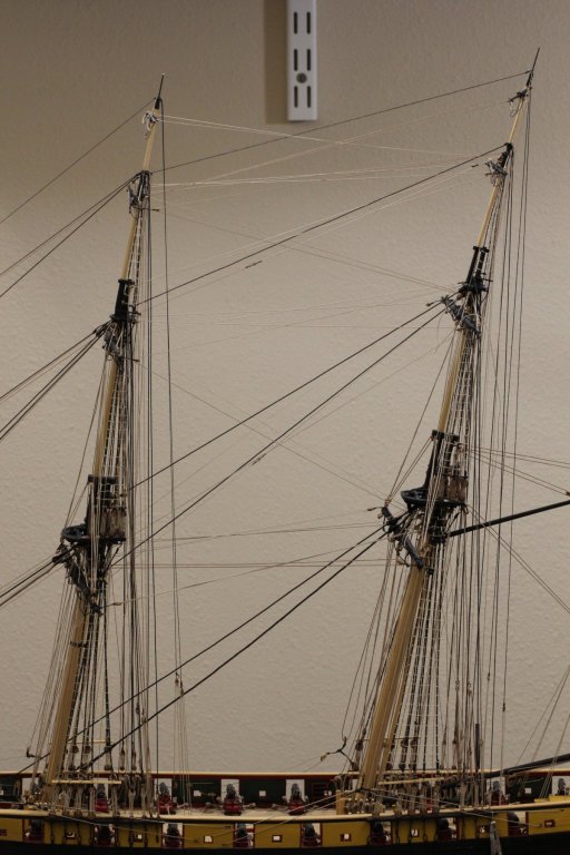
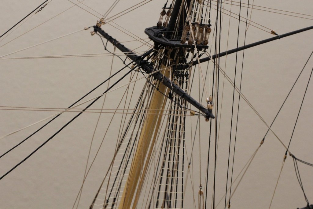
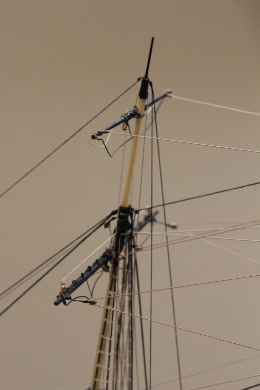
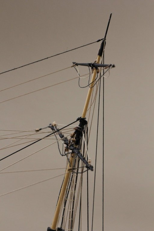
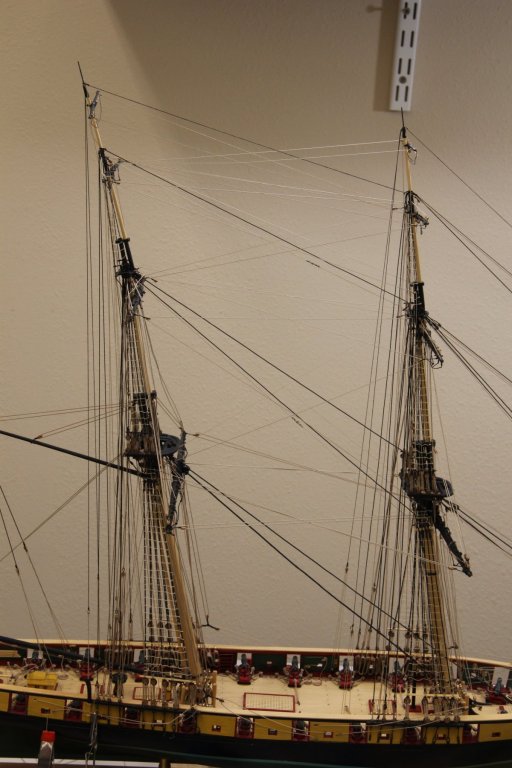
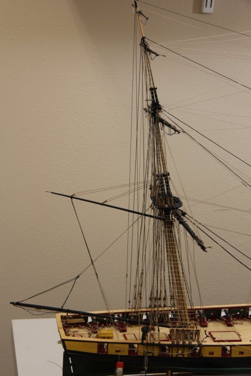
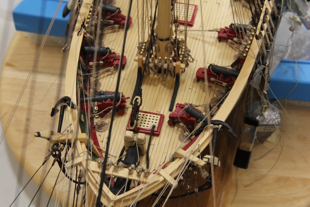
The rigging (except for the boat davit falls and the other ones I have forgotten (I am sure there must be some) is complete. I got all the braces rigged tightened (but not too tight - it is possible to loosen the standing rigging in places if you are not careful - don't ask me how I know. So here are so general shots of the rigging. If anyone wants to see something specific I will be glad to get some closer shots. It is really hard to get a good overall shot.


- 367 replies
-
- 5
-
-
- model shipways
- niagara
- (and 1 more)
-
A word on assembly sequencing. Do not leave the boat davits (the ones on the port and starboard sides - stern davits are not the problem) sitting on the laser sheet until the end. One of each has to slide down between the main channel and the rail/bulwarks and it will be much easier (and better) to widen the opening in the channel before the deadeyes and shroud lanyards are in place. In fact with them in place widening the opening is nearly impossible. The alternative in the thin down the life boat davits so that they will slide down into place. Thinning the boat davits will lead to davit breakage while trying to rig the lifeboat falls or install the life boats - do not ask me how I know. Here is a picture of the problem area. The forward davit broken while I was trying to rig the fall - for the second time! Luckily I have the set for the other side to use as a template for making a new one. If this were the last one being installed I would only have the empty laser cutout to go on. Anyway - my advice, get the davits (at least the two forward ones out while you are installing the channels an make sure you have enough room to get them where they need to be.
- 367 replies
-
- 3
-
-
- model shipways
- niagara
- (and 1 more)
-
While working up the courage to finalize the positions of the Fore and Main braces I found the boat davits and starting getting them ready for installation. In keeping with my previous decision to have as much of the topside material as possible made from yellow cedar I took this opportunity to use my new Byrnes thickness sander to take a piece of 5/32 X 5/32 cedar that I had down to the 1/8" thickness of the stern boat davits. That went very smoothly so I marked the profile from the kit piece and used the disc sander (also a Byrnes) to get close to the desired profile then finished up with sanding sticks. I laid out and drilled the holes for the tackle - dug out the wood between the two sets of holes on the top to keep the line from showing above the top and put two coats of flat varnish on them and placed them on the main rail aft. Here is they look like. I am still working the other davits as well as the metal straps that help hold them to the sides.


- 367 replies
-
- 2
-
-
- model shipways
- niagara
- (and 1 more)
-
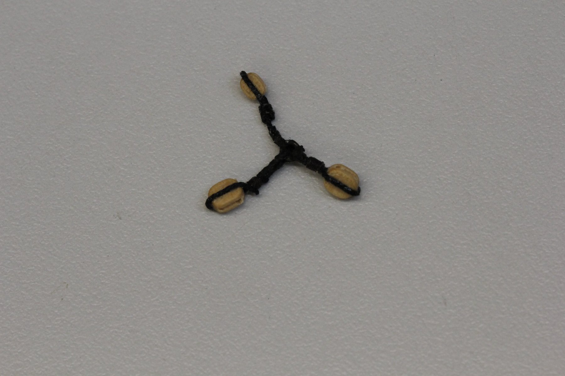
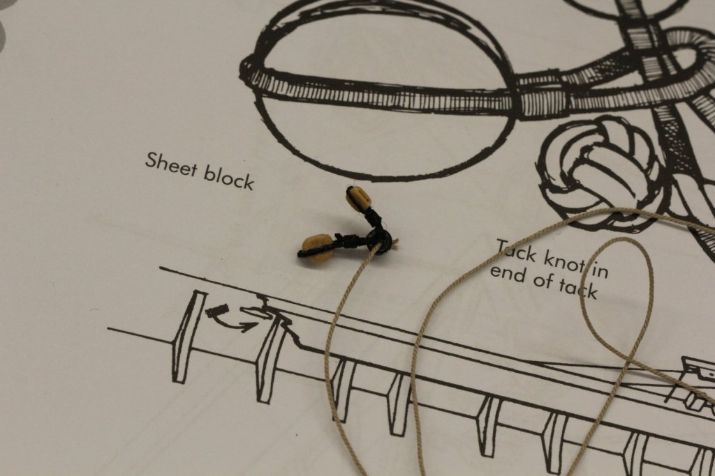
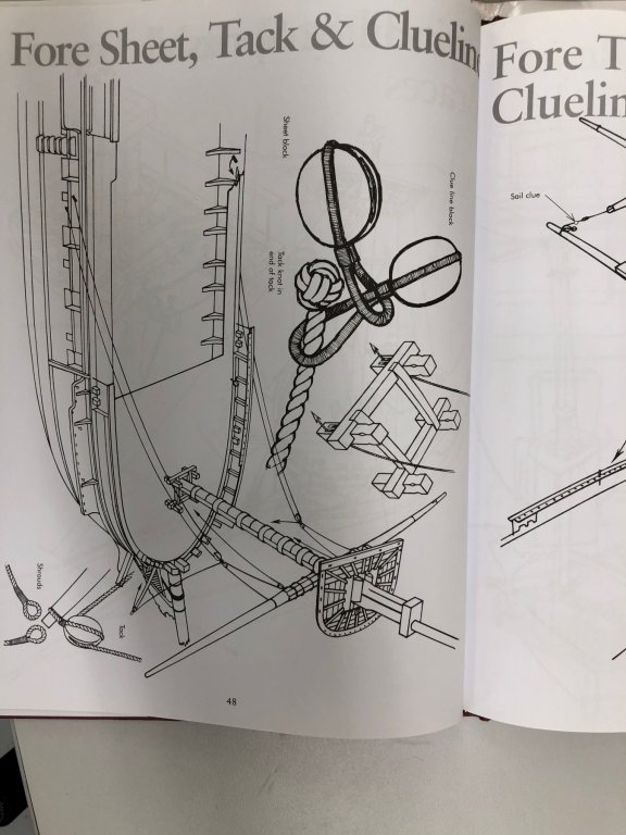
So after some fiddling around here are the Fore and Main Clew/Sheet/Tack combination blocks. I am still getting them secured and run to rope coils on deck. Letting the 50/50 mix dry between each movement. Starting to run the braces for the Fore Mast yards and looking for the boat davits as that is next after the braces. That a few odds and ends (chains on rudder, sea steps on the hull - I am sure there are others. Better reactivate my "To Do" list.
- 367 replies
-
- 4
-
-
- model shipways
- niagara
- (and 1 more)
-
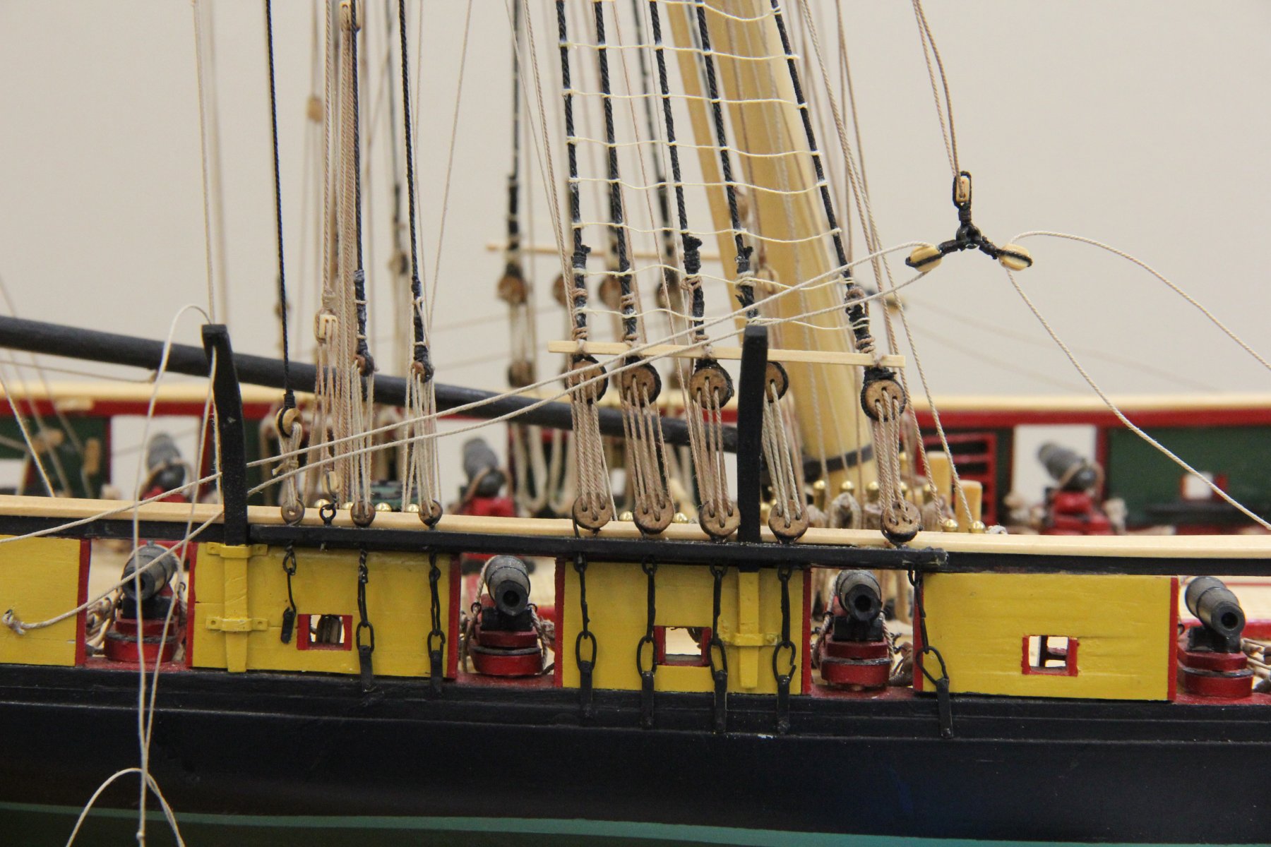
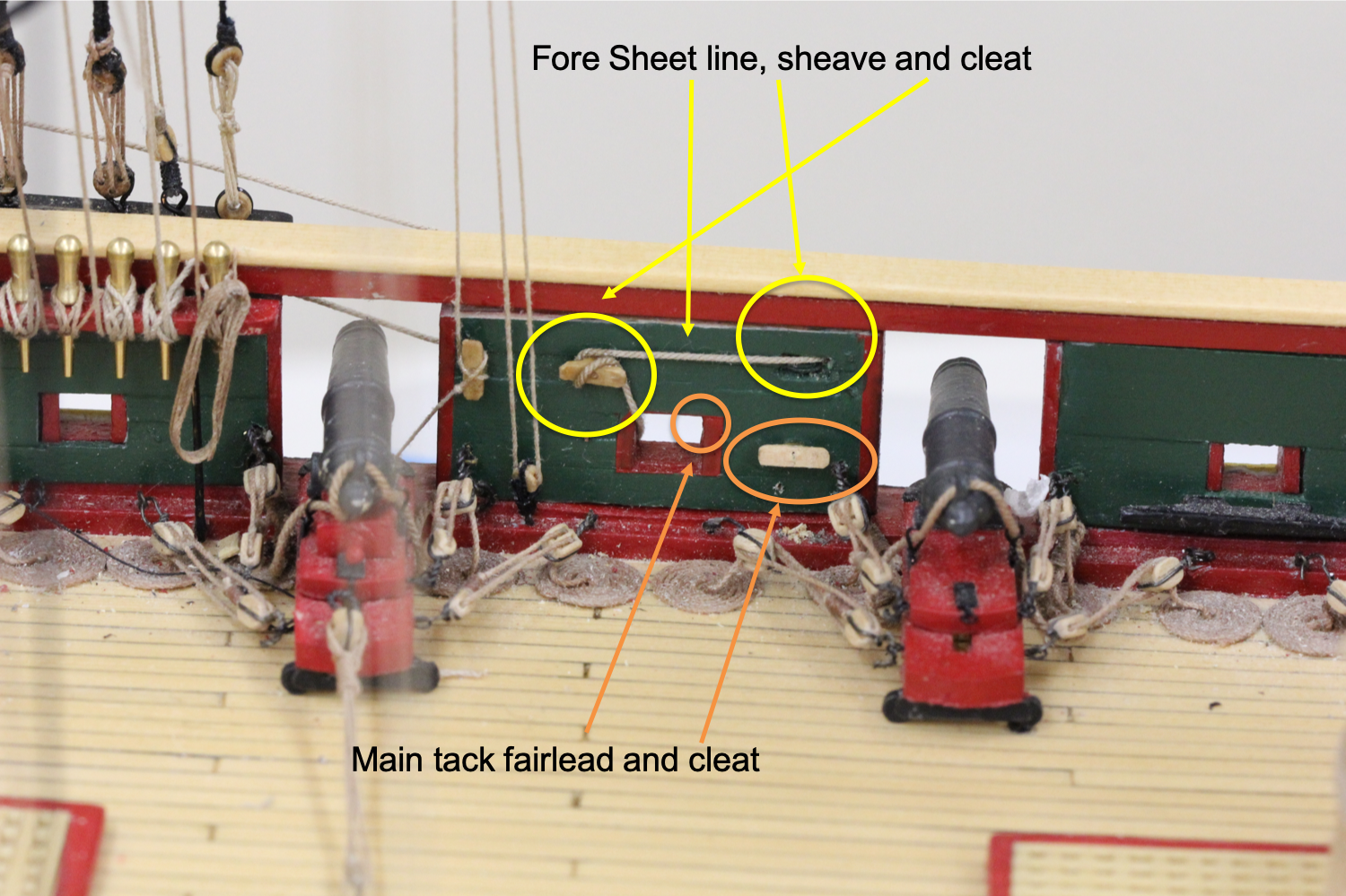
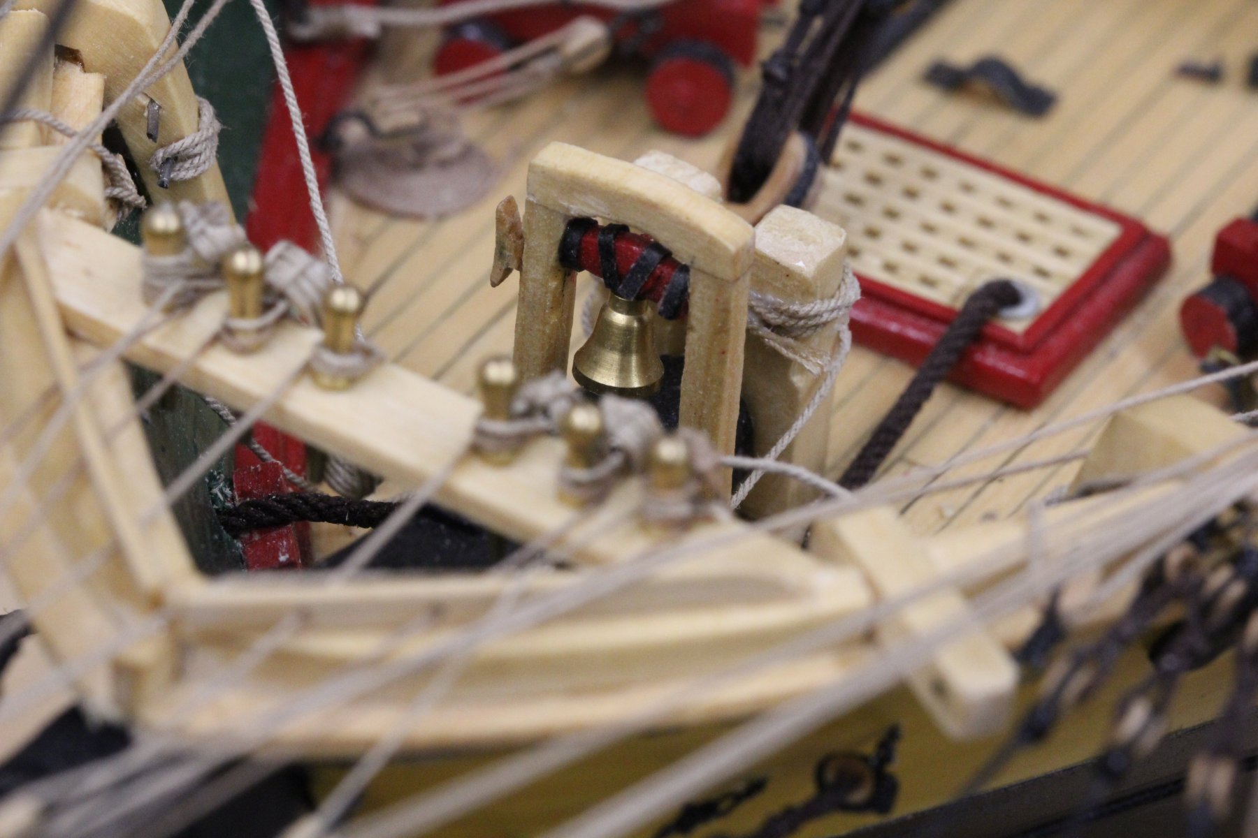
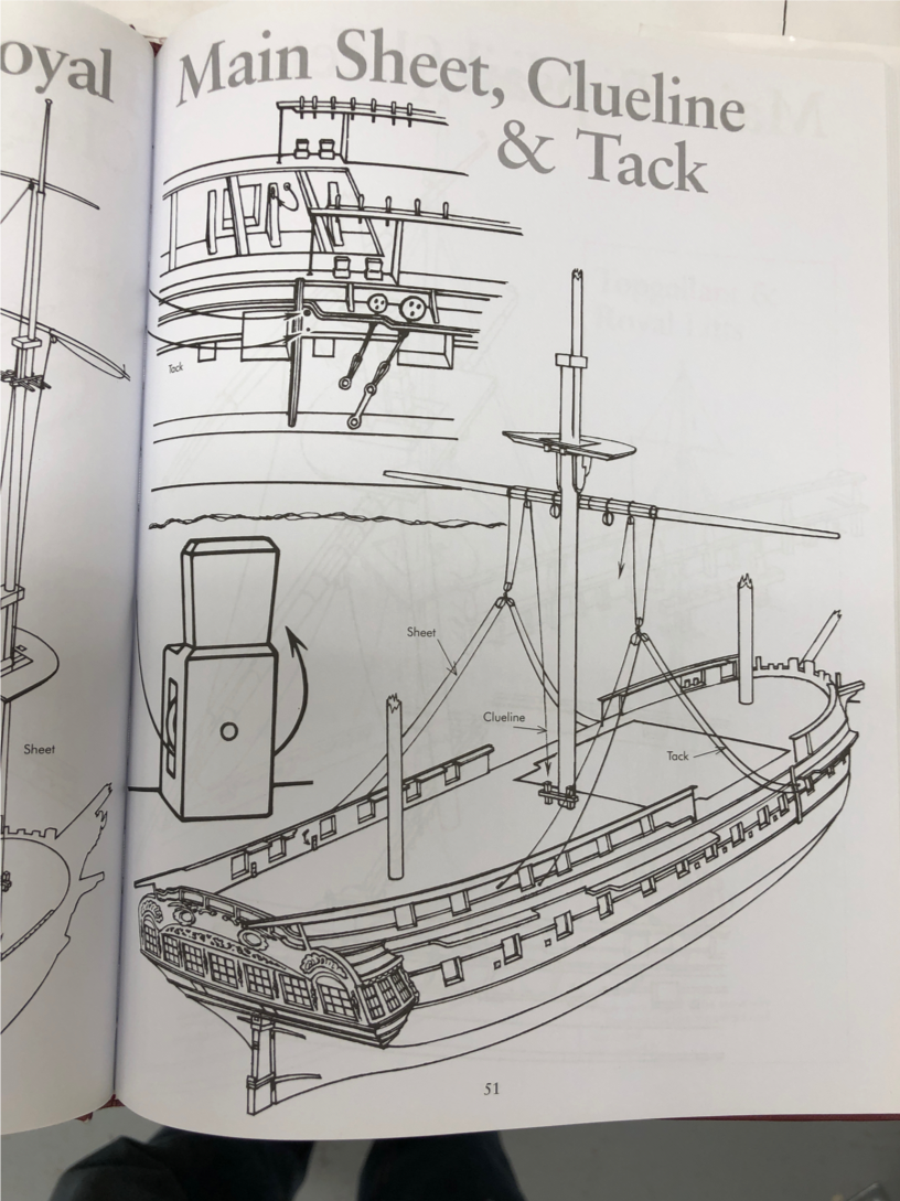
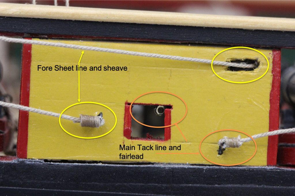
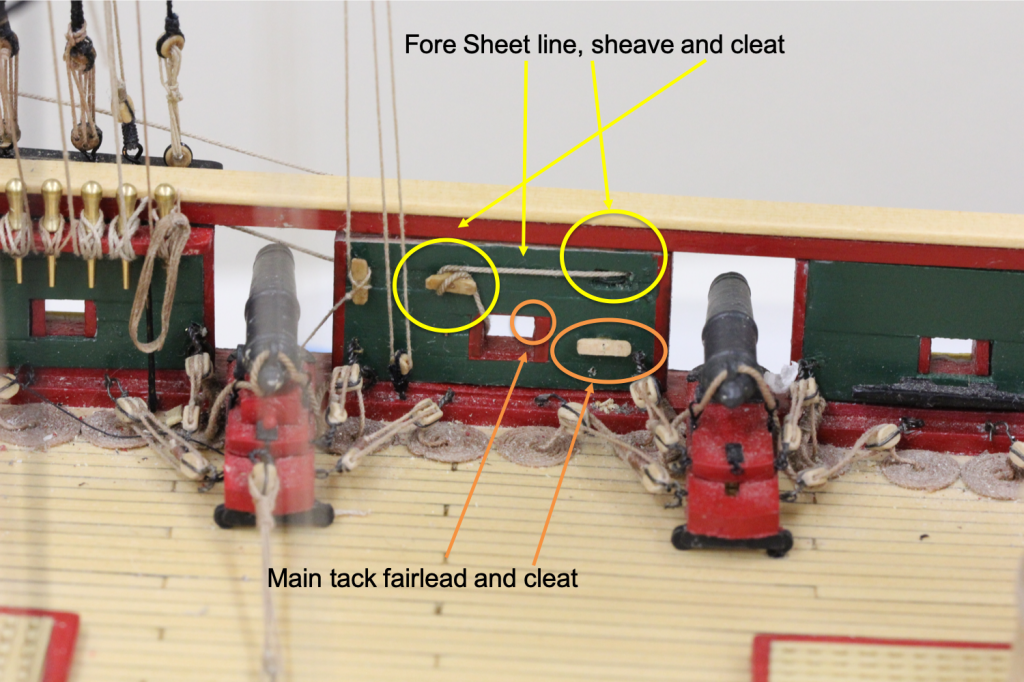
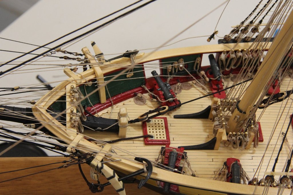
Thanks Jim. I have been "messing around" with the tack and sheet lines for the main and fore courses. I already bit the bullet and installed bumkins for the fore course tacks. The sheaves and cleats for the fore and main sheet lines are already in place so I don't have to do anything there except install the eyebolts on the exterior and run the lines. So with the bumpkins installed the fore course tacks and sheets are ready to go. For the main course the sheets are ready (eyebolts installed) but the tacks are a question. The plans say that the main course was "seldom used" but if used "hook the tack to any convenient place on the fore channels". I decided to at least partially replicate for the main tack what is present for the fore sheets. I was not ready to cut into the bulkheads to put sheaves in so decided to put a fairlead in the sweep port and add a cleat to the bulkhead for the main tack. Using the same distance as from the fore mast to the bumkin for the main mast to tack location puts it very close to where the fore sheet in belayed so I added the fairlead and cleat in the same area (between gunports 4 and 5). I also went to my "to be installed" box and found the ship's belfry and since the fo'c'sle is "done" decided now was as good a time as any to install the belfry. And looking forward to the braces I did a trial run of the main braces.

- 367 replies
-
- 6
-
-
- model shipways
- niagara
- (and 1 more)
-
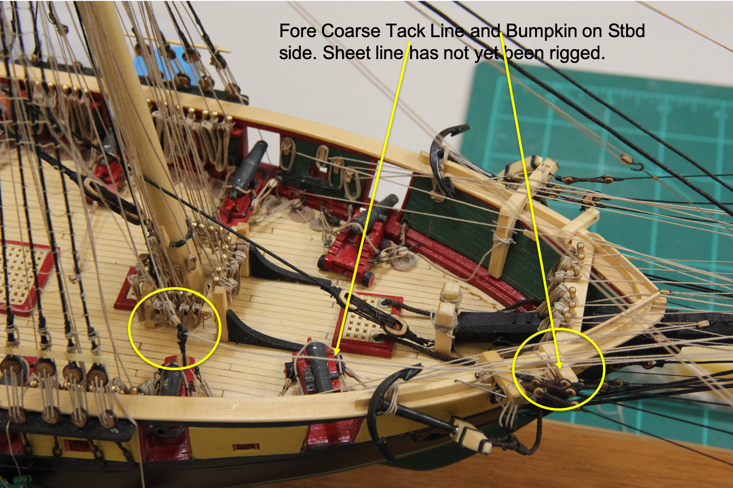
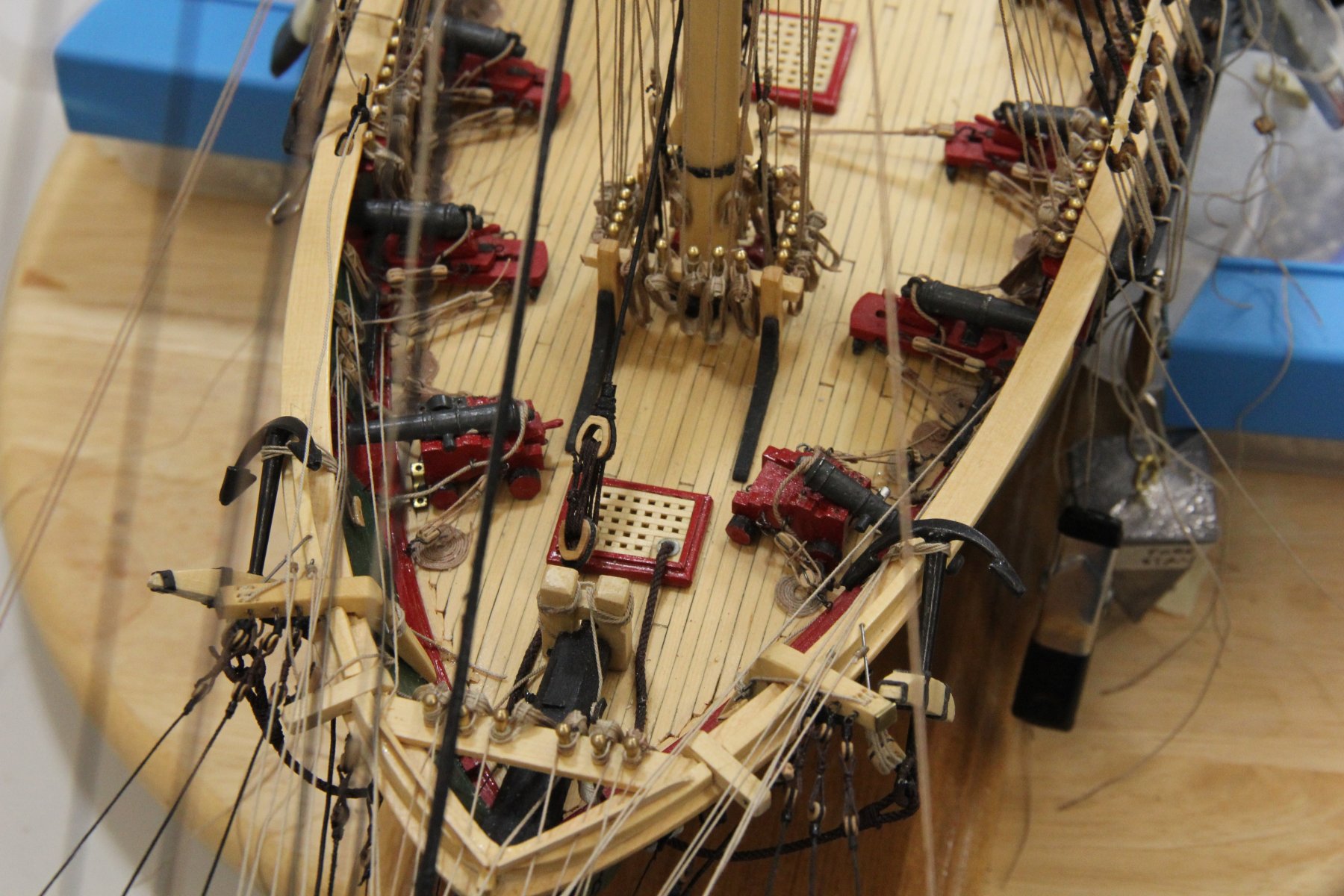
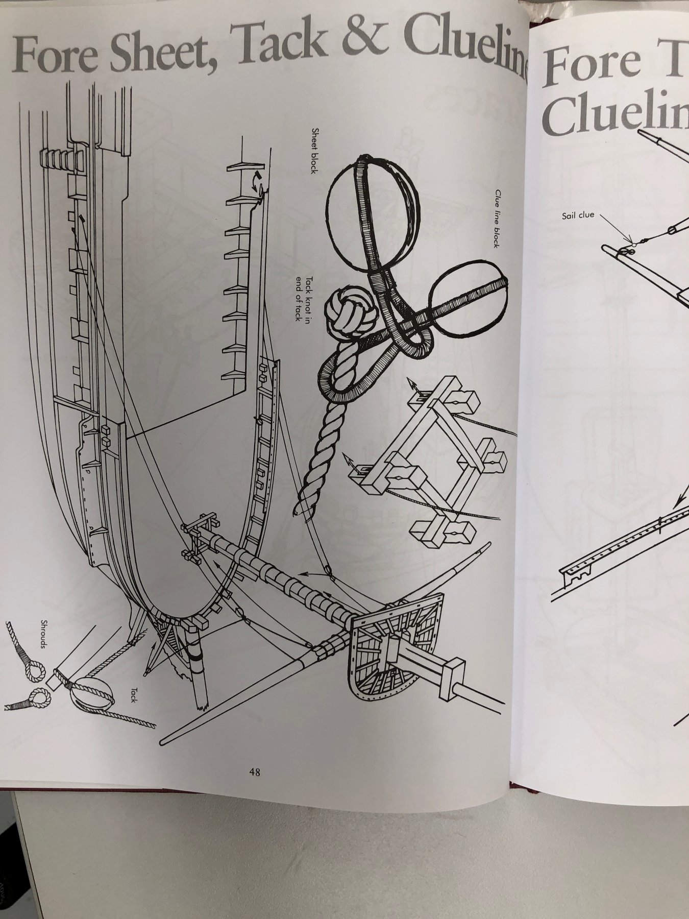
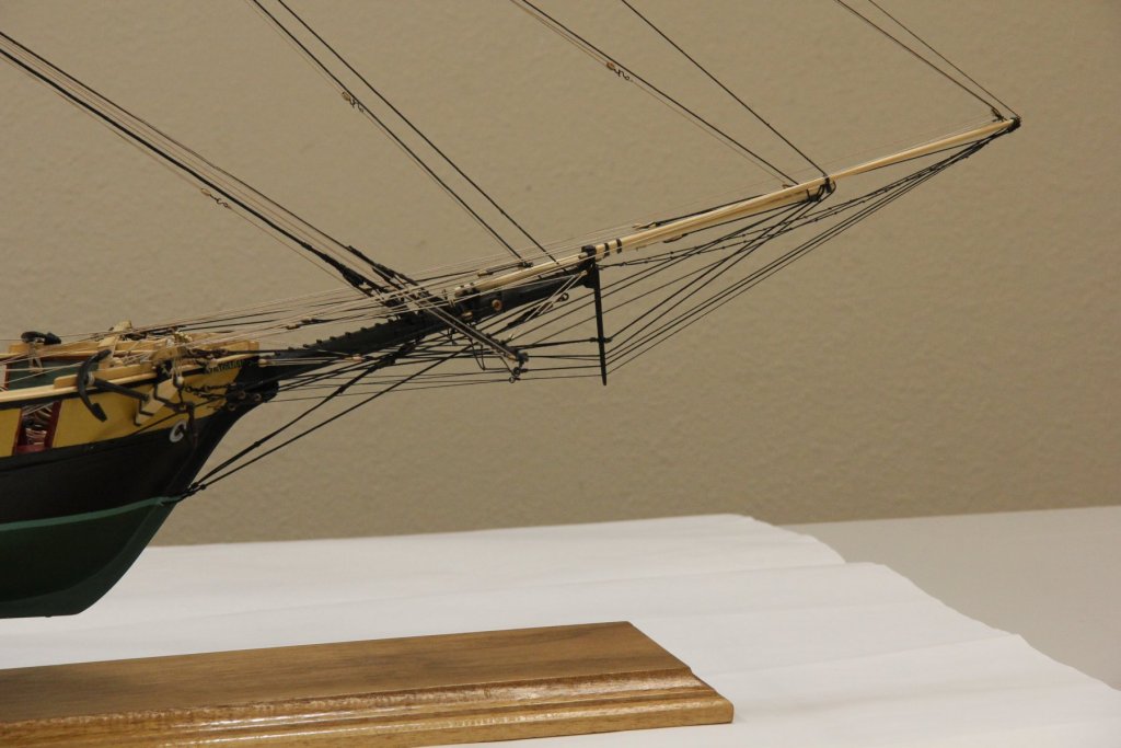
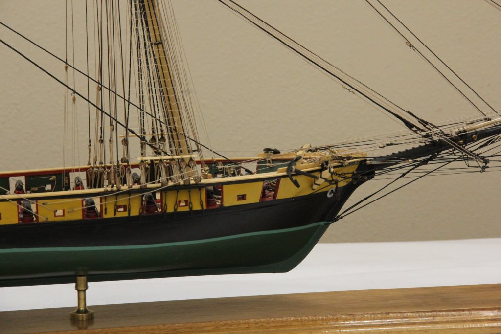
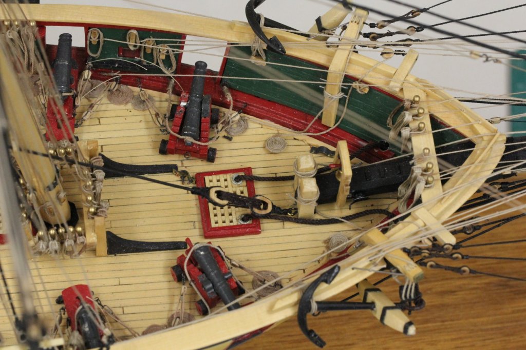
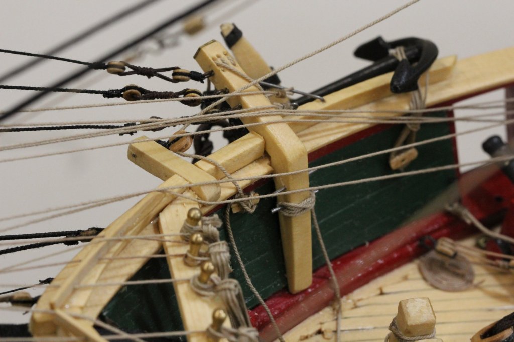
I got the fo'c'sle almost finished. When I added the bumpkins I also added a new cleat on the upper bulwark just inboard of the bumpkin for the Fore Coarse Tack Line to belay. I rigged my version of the tack/sheet/clew tackle shown in Petersson. I used a 1/8" Bluejackets plain bullseye to hold the two blocks and provide a place for the bitter end of the tack line. And it works pretty well although I have not rigged the sheet line yet. There is shot below of the tack line/bumpkin as they stand for now - I think I need to reroute the tack line either over or under all of the head sail sheet lines that are running over the boiw area there. Making steady progress elsewhere. I think I have the rats nest depopulated and am working the pin rails making things tight and putting coils on the belaying pins. I also got the ratlines completed on the stbd side. Port side tomorrow - I promise. Here are some shots of the fo'c'sle as well as the port side fwd pin rail. The goal of getting everything done by the 18th (three week road trip starts then) still seems feasible.

- 367 replies
-
- 6
-
-
- model shipways
- niagara
- (and 1 more)
-
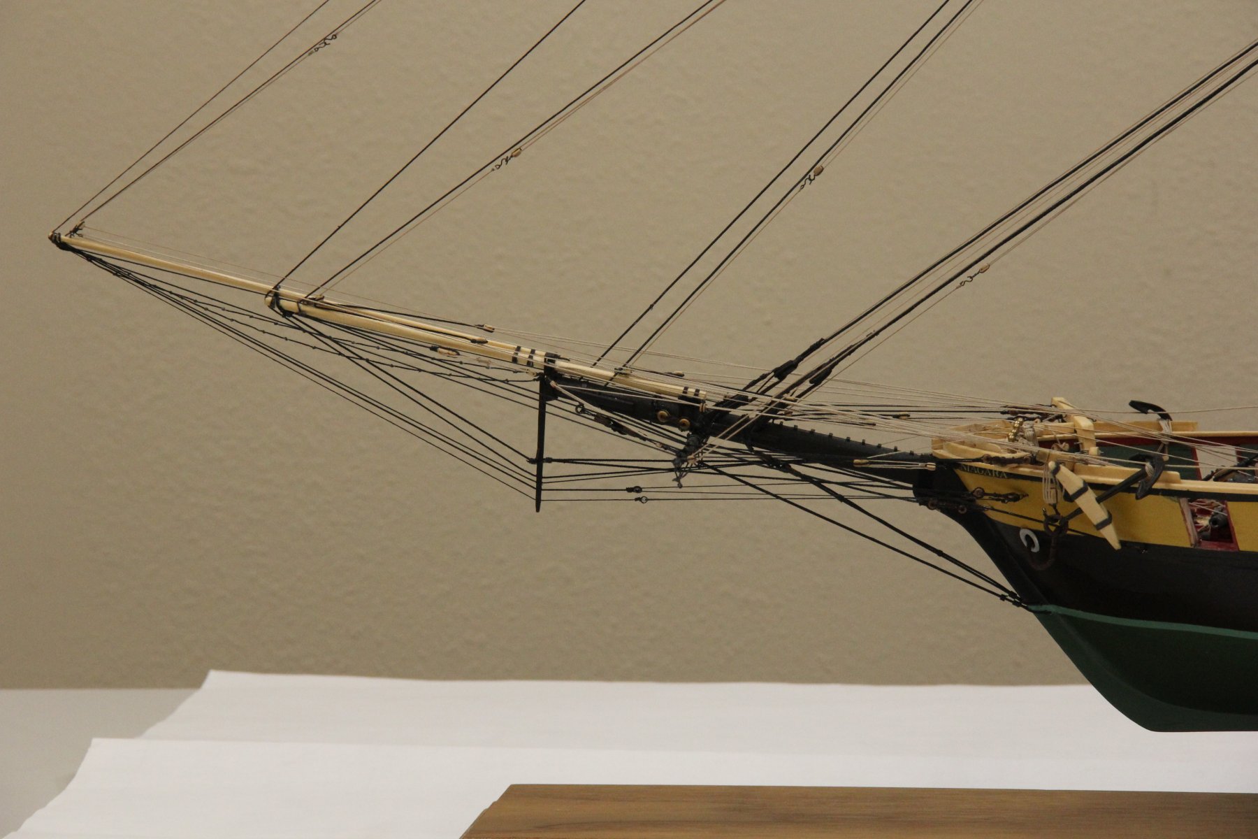
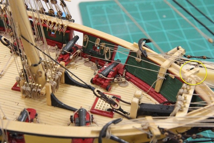
Except for some rope coils on deck for the anchor tackle, the fore deck and forward fife rail are complete (as far as I can tell at this point). I have both anchors "catted" and lashed over the rail. All the lines terminating at the forward pin and fife rail have been secured and rope coils added (where I could - in some cases the pins are so close together I can't get a coil on every pin without having them too bunched up IMHO. Now it is on to my favorite task (NOT) - ratlines. I still have to connect the Top Mast, Top Gallant and Royal stays forward and tighten and secure the lines at the forward pin rails then it will be on to the braces and course tack and sheet lines. I did decide to add the bumpkins for the Fore Course Tack lines, much as Darrel (6Ohiocav) did. You can see the port one in the yellow circle in the photo below. Still working the stbd side so I will hold off further pictures of the fo'c'sle until that is finished.
- 367 replies
-
- 6
-
-
- model shipways
- niagara
- (and 1 more)
-
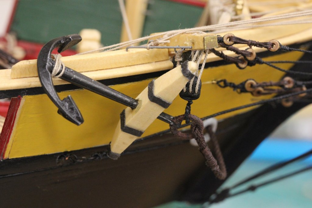
Working on getting to area forward of the Fore Mast complete. This includes the anchors one of which I got done last night. I painted the entire anchor lifting block black since I had to paint the "hook" black after I mused solder to try and smooth out the "shank" made from winding the strouping wire around itself. I am not sure I like the look. May try something different (like leaving the block natural) on the other side.
- 367 replies
-
- 3
-
-
- model shipways
- niagara
- (and 1 more)
-
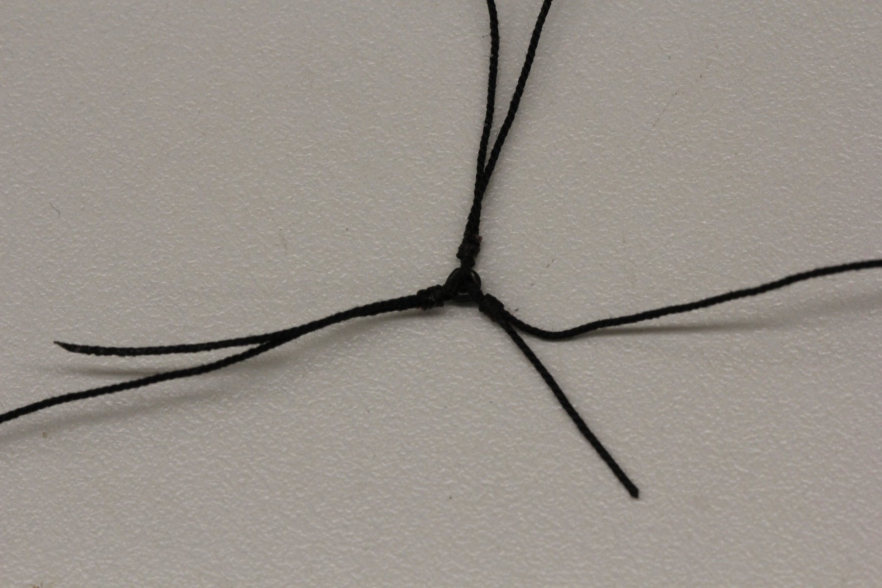
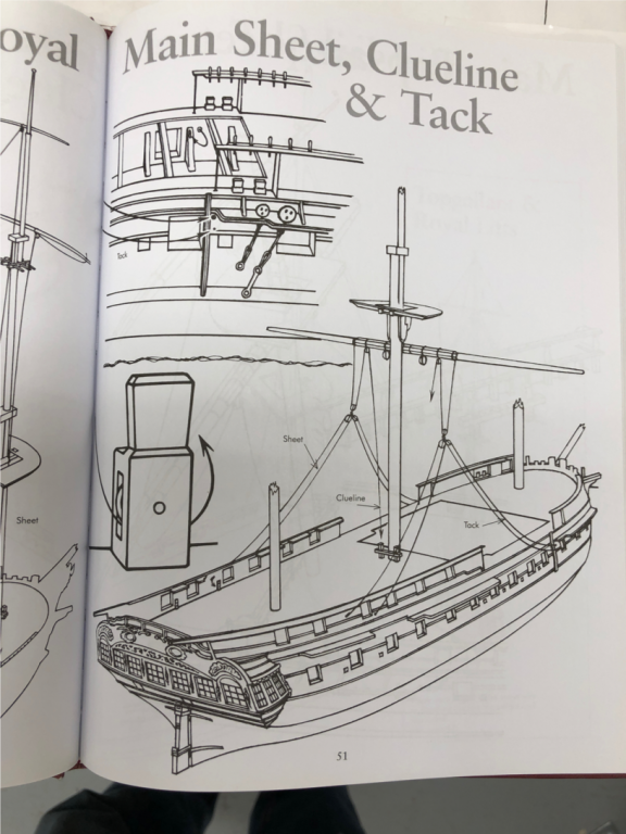
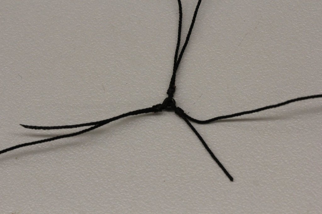
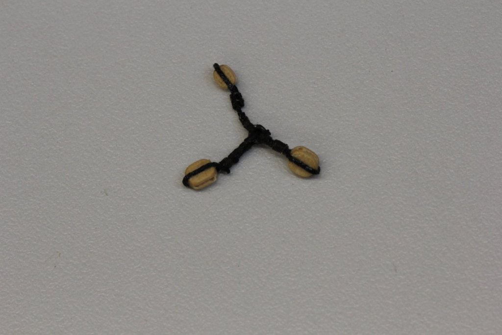
I thought I had the photo order correct but I guess not - I corrected the photo numbers below to correspond with how the came out - sorry. While waiting around for glue to dry and looking back on the Main Mast rigging I saw the note on the sail plan about the Fore Tack and Sheet and that the Main Tack was seldom used. I know I had included the sheaves just forward of gunport 10 for the Main Sheet so thought I might as well use them. I looked in Petersson's "Rigging Period Ship Models" (photo 4) and it shows a version from a somewhat earlier period (1780s). So to rig the Main Sheet and Tack I need a "triple header" tackle with two 5/32 S and one 1/8 S blocks (sheet, tack and clew in that order). I saw how this was done on Darrel's (60hiocav) build log but thought I would try something I thought would be easier (if probably less "authentic"). I started with a 1/16" Britannia metal plain (i.e. no "teeth") bullseye from Bluejackets. I then attached three "strouping lines to the bullseye (photo 3). I also painted the bullseye flat black. Now I added the three blocks (order does not matter) to the strouping lines and you have the "triple header" block set for the Main Sheet, Tack and Clew (photo 2). How the Clew is rigged is different in Petersson than on the plans. On the plans the bitter end of the Clew is attached to the base of the clew block on the yard. In Petersson it is attached further out on the yard. I think I Petersson is probably correct as this would seem to give a better direction of effort when using the clew to furl the Main Course. Fore the Fore Course Petersson is quite different from the plans (photo 1). The tack goes to a "bumpkin" (the pole fwd of the cathead) which is no where on the Niagara plans but does exist on the replica ship in Eire. Darrel (6Ohiocav) added the bumpkin to his Niagara - I am thinking of doing the same but have not committed to that course yet. In any event I need to fabricate two additional block combinations for the Fore Sheet/Tack/Clew as well although these only have two blocks (sheet and clew) and a "hole" for the tack line. The tack block goes on the bumpkin or on a "bridle seized in a hole in forward chock rail. Belay to rod in cathead" according to the plans. I will build the block combos and think about the tack.
- 367 replies
-
- 3
-
-
- model shipways
- niagara
- (and 1 more)
-
Very nice Tom. Much cleaner than mine at the moment. There seems to be no end to the debris that finds it was onto the deck. And the closer you to finishing the harder it gets to "clean house".
-
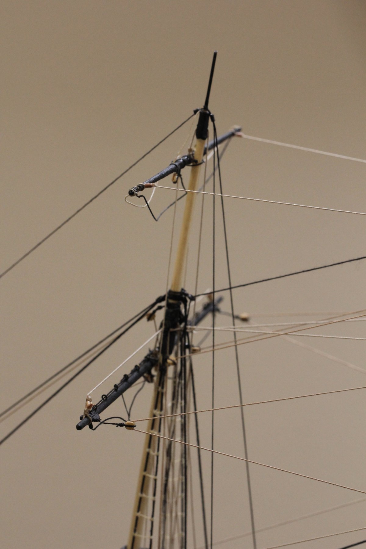
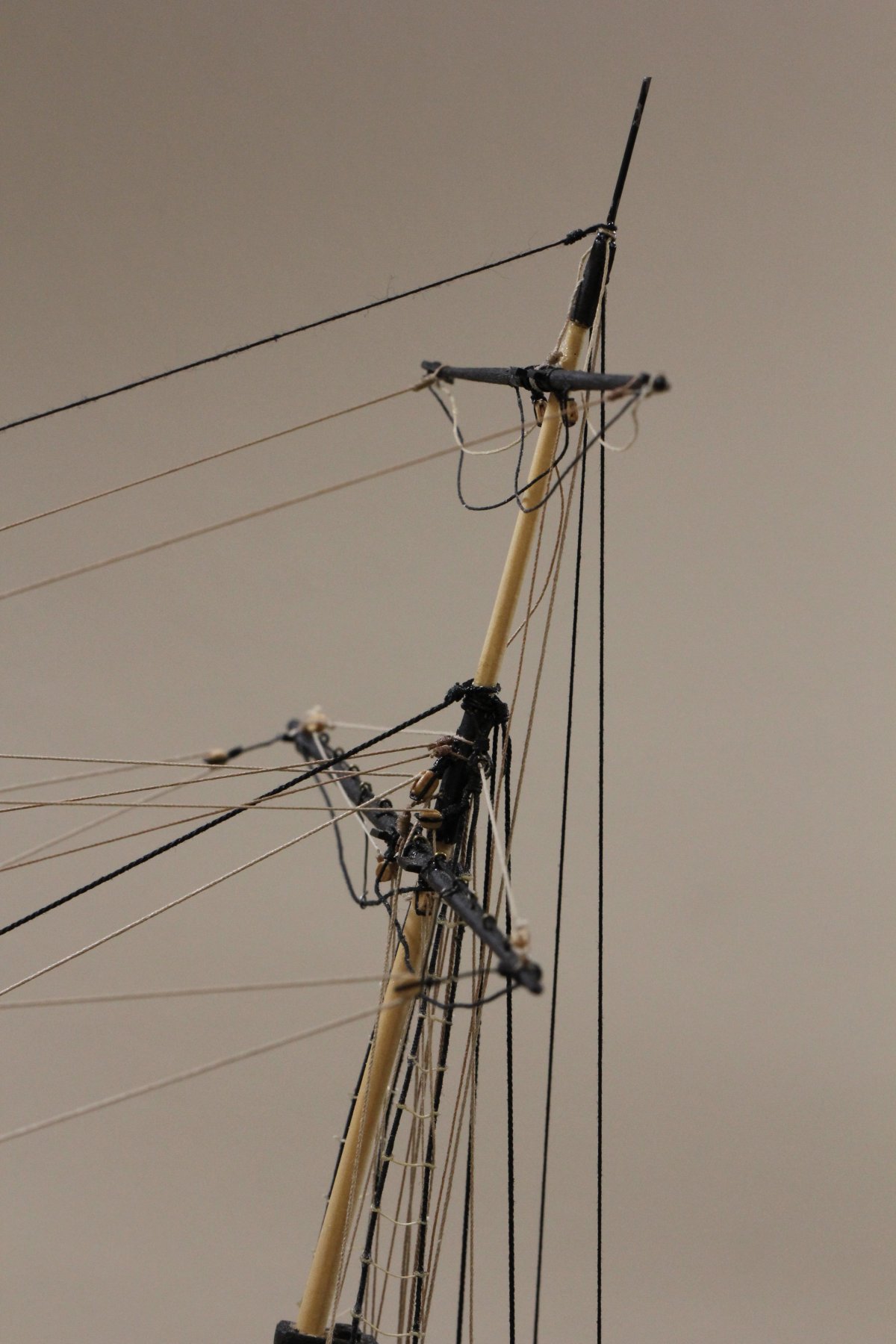
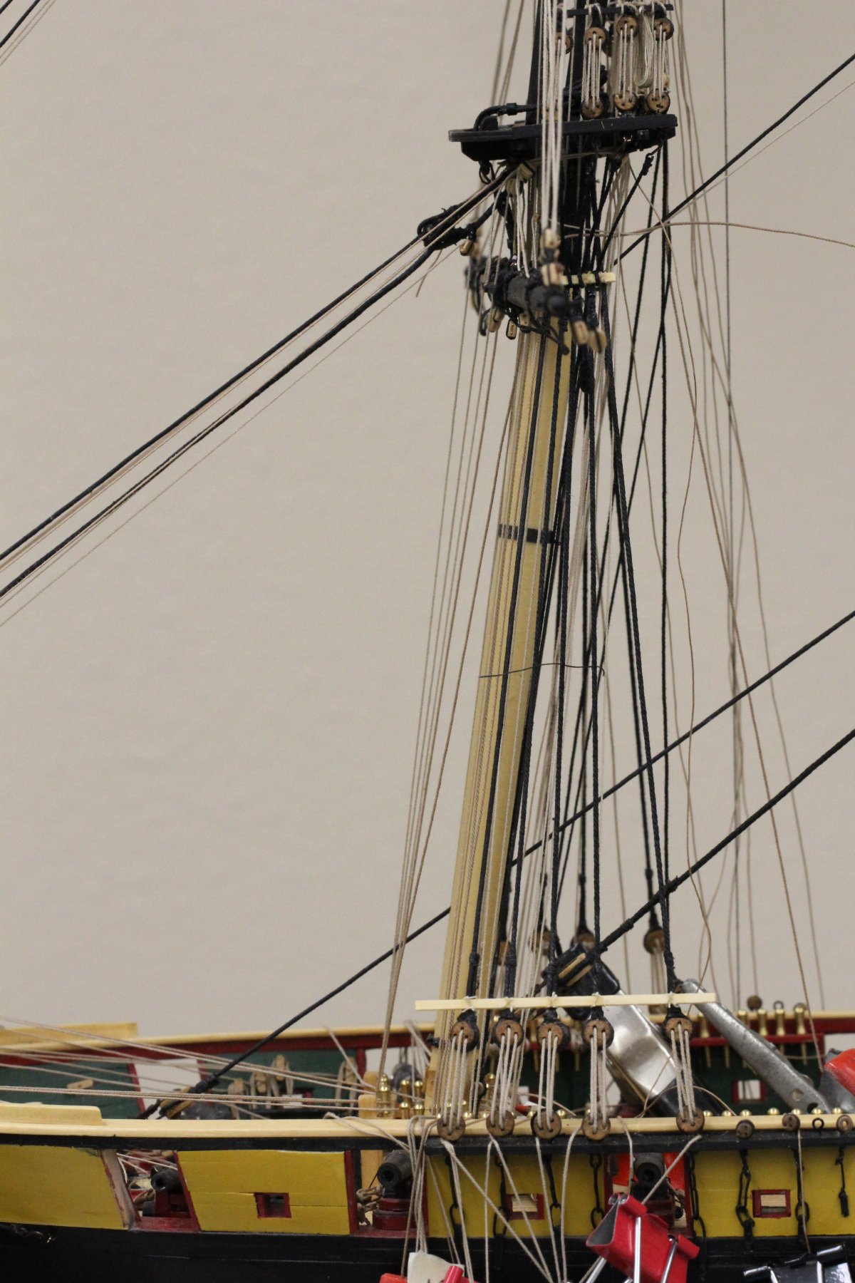
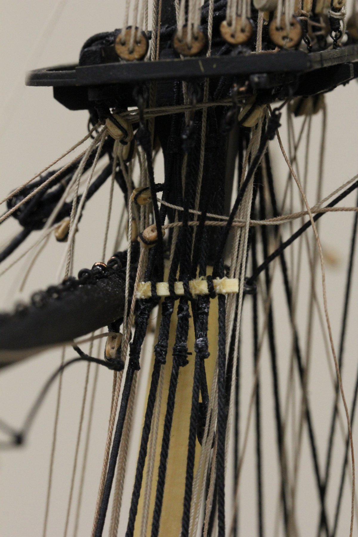
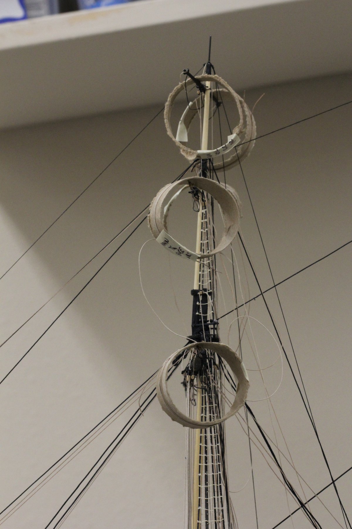
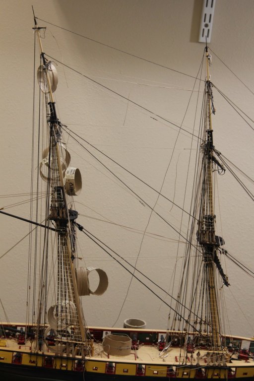
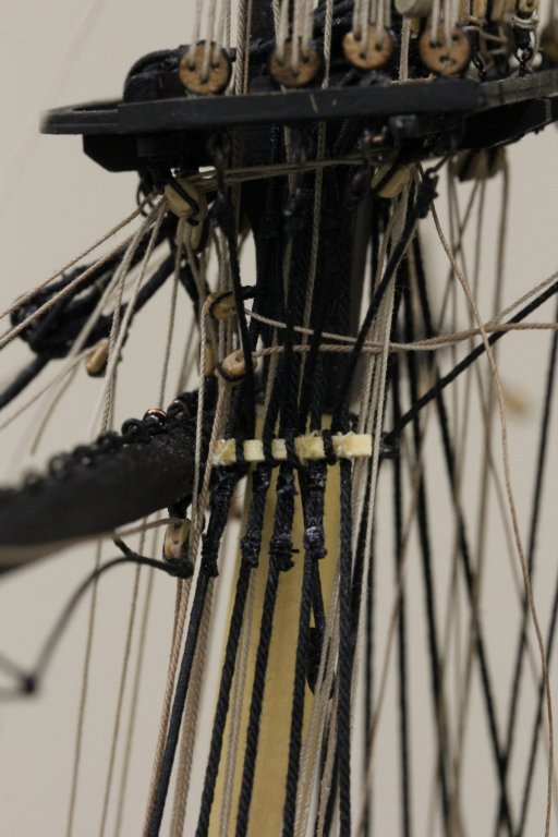
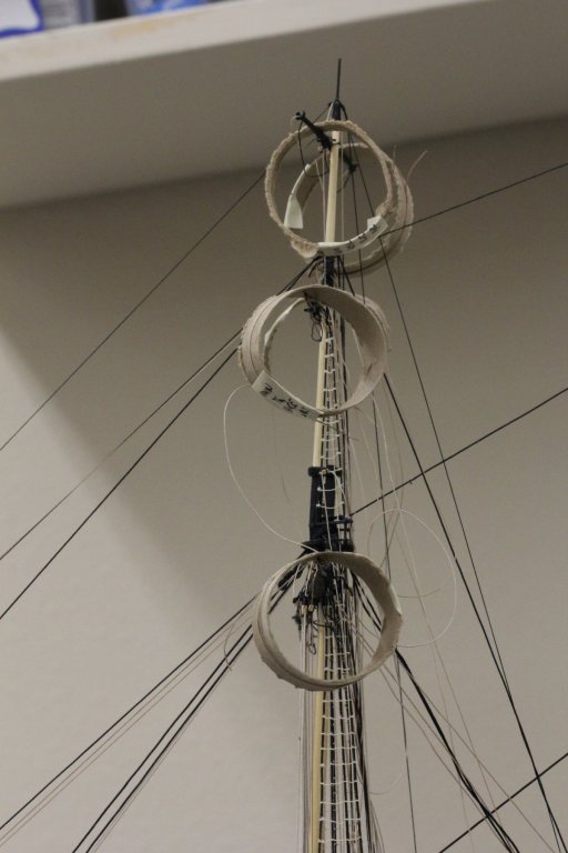
With mast now stabilized fore and aft I went ahead and installed the lanyards on the rest of the Fore Mast shrouds. I added the sheer poles (not really poles but...). I cheated and used slightly larger stock than the plans call for - 1/32 X 1/16 for both upper and lower sheer poles. With the upper sheer pole installed I added the futtock shrouds on that side. I think this looks better than the aft set and this time I actually looked at the plans for the futtock shrouds are lashed to the forward four of the lower shrouds as they should be. On the Main Mast I used the aft four shrouds for some reason I can't remember. I think I started aft and worked forward - maybe it was just happenstance. Anyway the futtocks are done on one side. I looked at the plans (again those damn plans) and decide to rig the Main Mast braces to their belaying pins now and adjust to the required length on the "other end". The toilet paper tubes on the Fore Mast hold the remaining line for the Main Mast braces (at least the three upper yard arms - the course yard tubes are on deck). I now have all the braces (Fore and Main Masts) accounted for. These will be the last lines to be rigged. I have most of the other running rigged belayed and will finish what I have rigged tomorrow. Then I will make a final check for blocks that need stropping, lines that are missing (I know at least the Fore Course sheet lines have yet to be rigged, I am sure there are others) and other odds and ends (like the anchor tackle). I want to make a final push to completion next week before we depart on a three week road trip up and down the east coast.

- 367 replies
-
- 4
-
-
- model shipways
- niagara
- (and 1 more)