cdrusn89
-
Posts
1,919 -
Joined
-
Last visited
Content Type
Profiles
Forums
Gallery
Events
Everything posted by cdrusn89
-
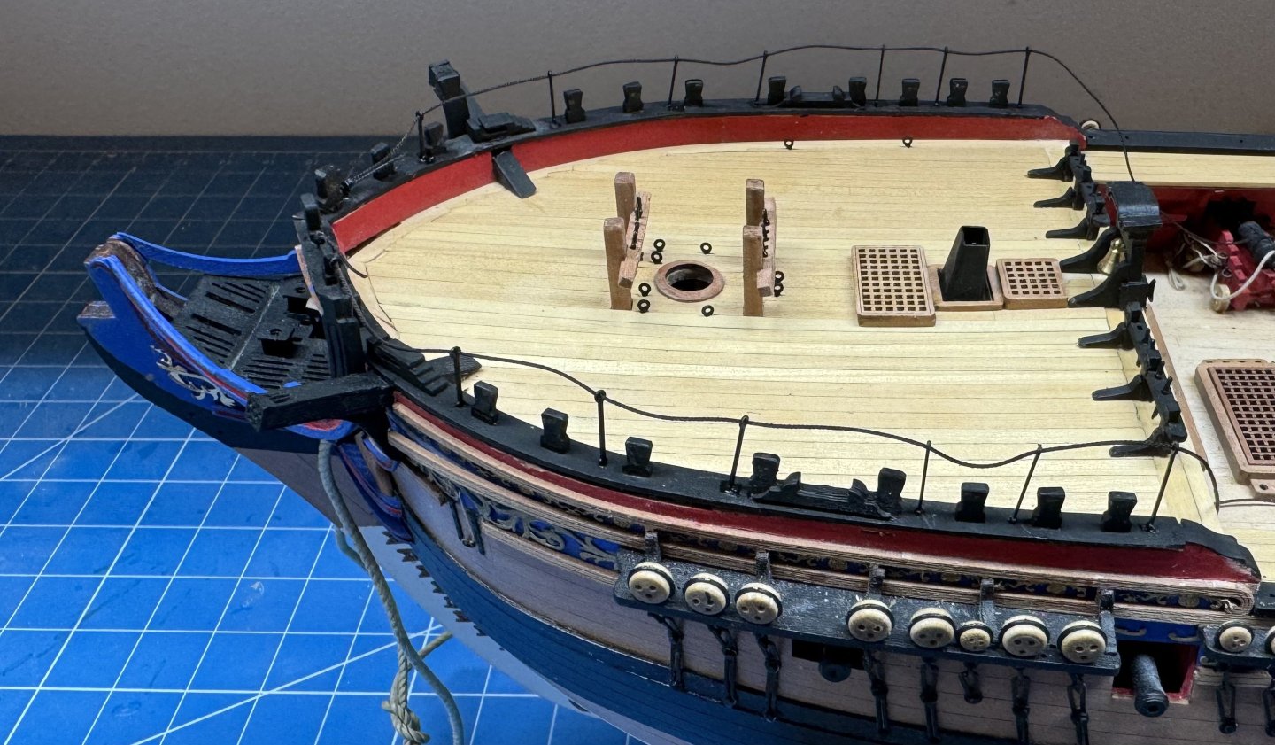
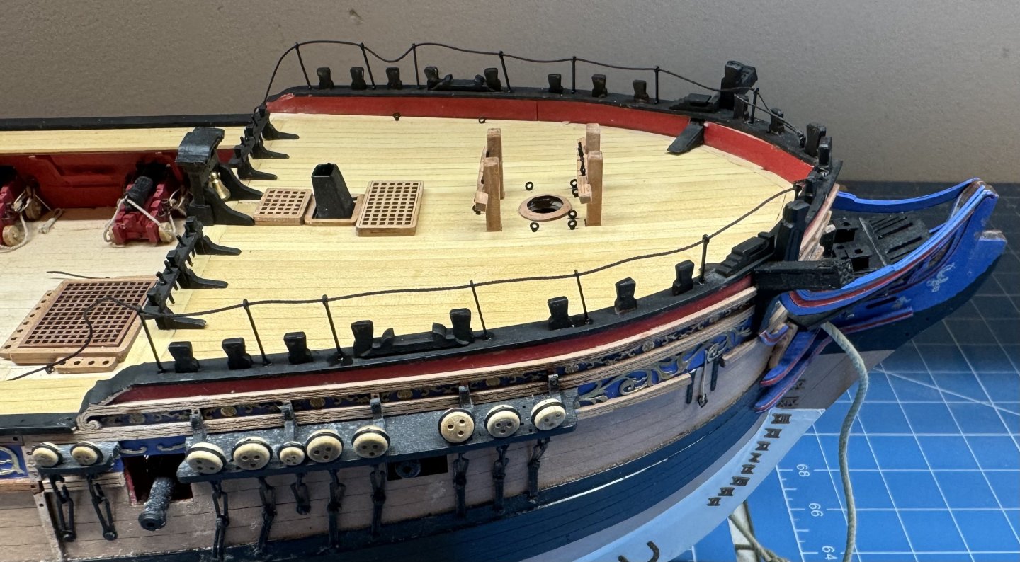
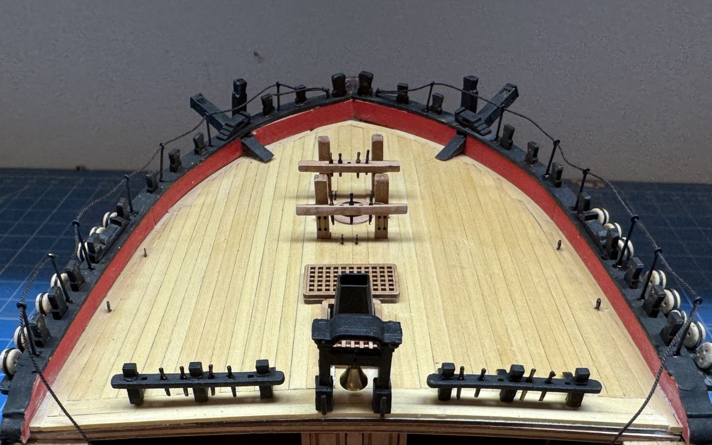
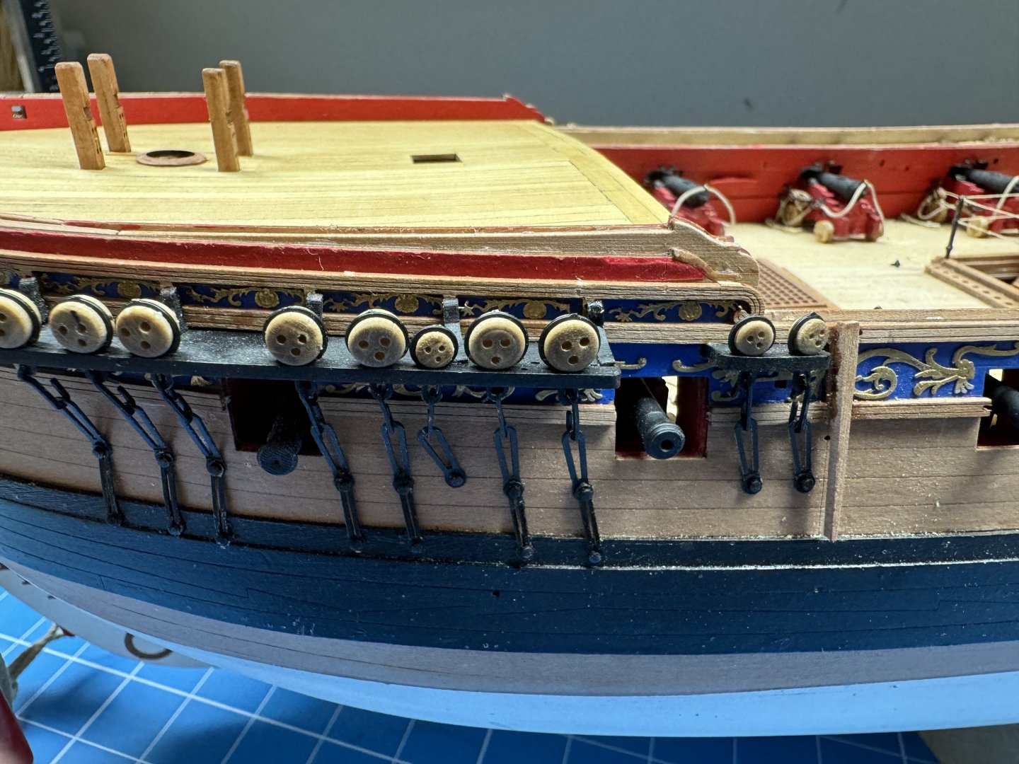
 I only "thought" I was done with the forecastle. When I moved to the q-deck I thought it appropriate that before I started the timberheads, etc. that I should add the various eyebolts and cleats that are shown on the drawing (Sheet 15). As I looked over that drawing I noted a bunch of eyebolts that are on the forecastle too. Hmm, I guess when planking the deck yourself you loose all the markings on the maple deck and (at least in my case) reminders that "something goes here". So I went back to the forecastle and added the eyebolts shown on the drawing. While I was at it I checked the rigging plans and added the belaying pins required to the pin racks. Then I reconsidered the stanchions and lifelines. My original thought was to leave these off for now as they are pretty vulnerable to errant elbows, shirt sleeves, etc. On second thought most of the stanchions are behind the shrouds and will be harder to get at once they are in place, and they will be the first items added once the masts are in place (more or less the next step after the q-deck is "populated"). So I added the stanchions and rigged the lifeline but left plenty of extra line so I can run it below the stanchions and hopefully keep it out of the way until needed. FYI - I used .018" Syren ultra Dark Brown line and with the end dipped in thin CA the line was a near interference fit through the stanchions. Not sure what would have happened if I used the kit provided .5mm (.0196") line but if that is used care is required to thread it through the stanchions. Maybe the primer and paint I used restricted the stanchion opening more than I realized. Anyway here is the now (hopefully) really completed forecastle.
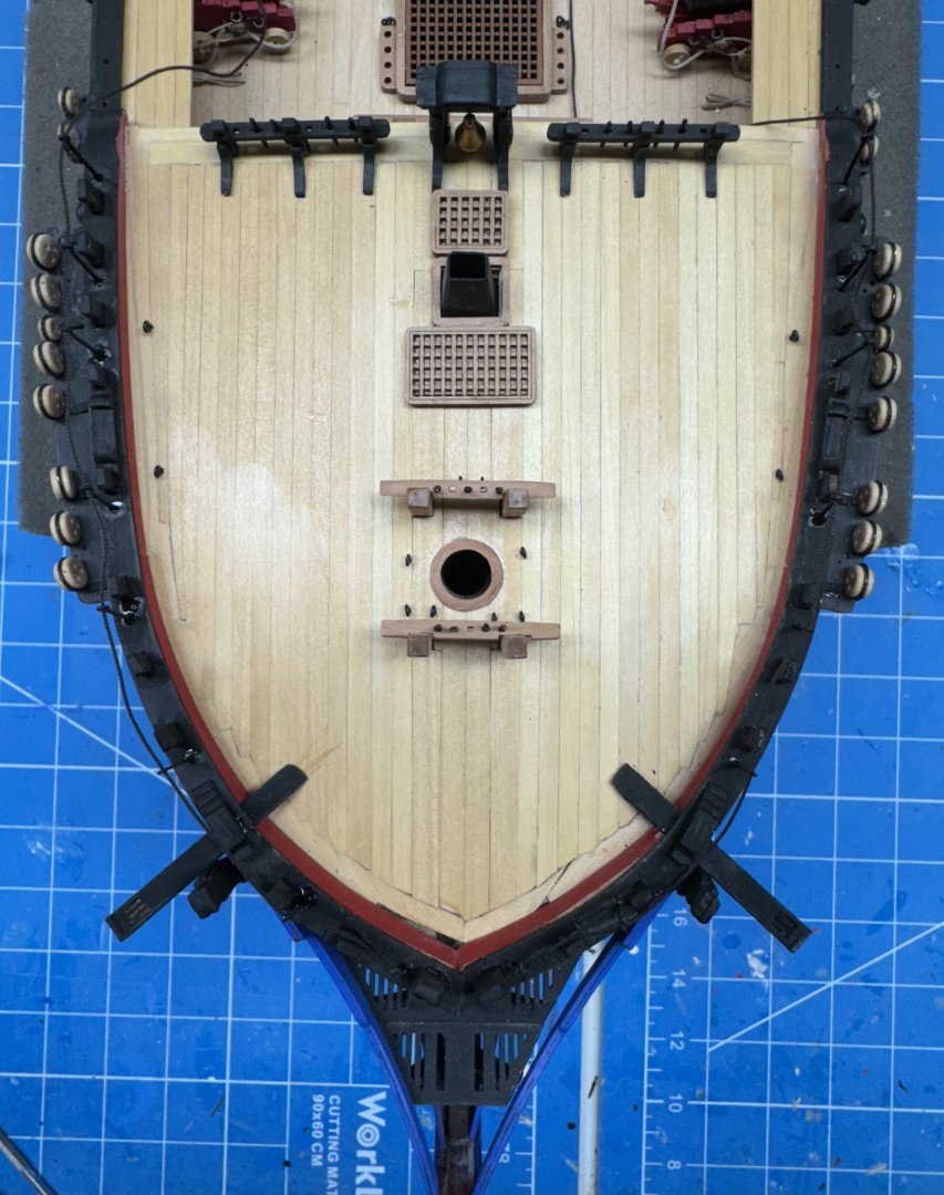
- 422 replies
-
- 5
-

-
- Vanguard Models
- Sphinx
- (and 1 more)
-
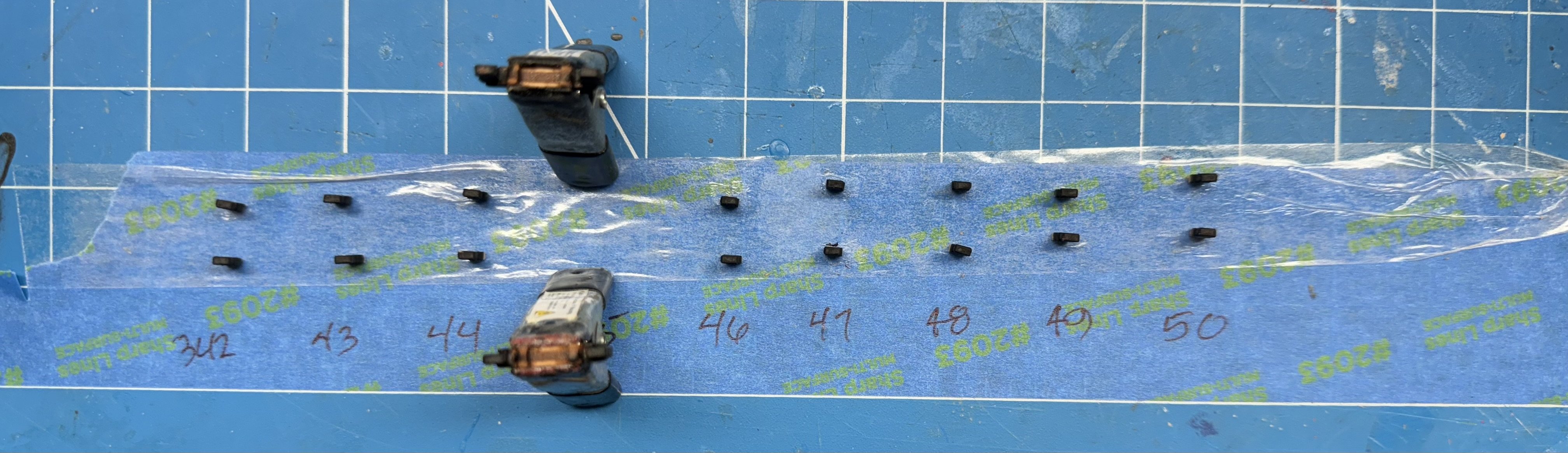
Forward timber heads are next. Since Vanguard went to the trouble of numbering each timberhead individually I am assuming it would be a good idea to keep track of them during the subsequent "processing". Here they are (less the two very most forward which will join the fun shortly) after having the carrier tabs removed, the edges softened, the "tab" tapered a tad to ease installation. and a first coat of flat black. I tried fitting them "unaltered" and it was a struggle so hopefully I have not done too good a job and now they are "unsteady" in the slot.

- 422 replies
-
- 4
-
-
- Vanguard Models
- Sphinx
- (and 1 more)
-
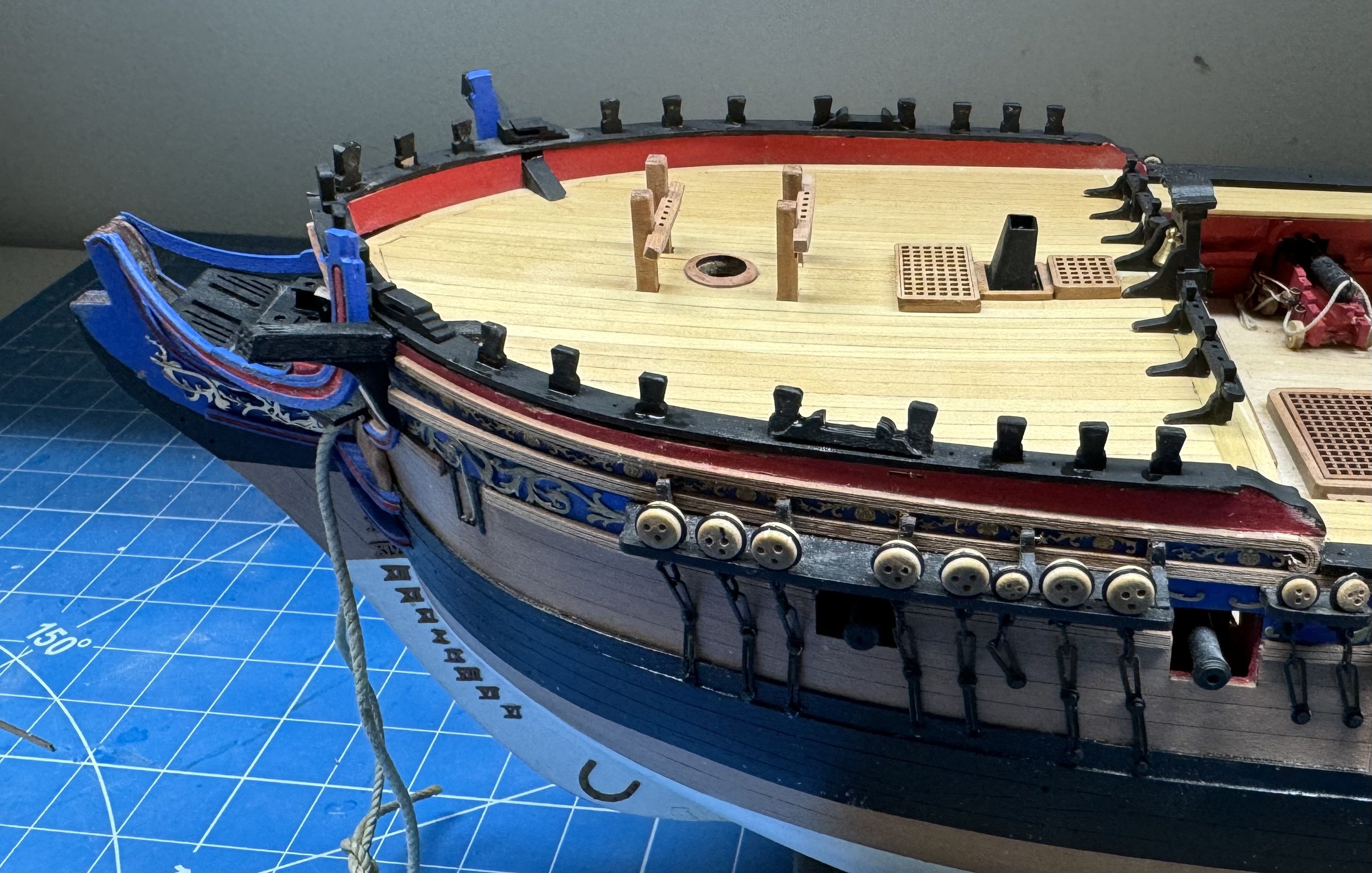
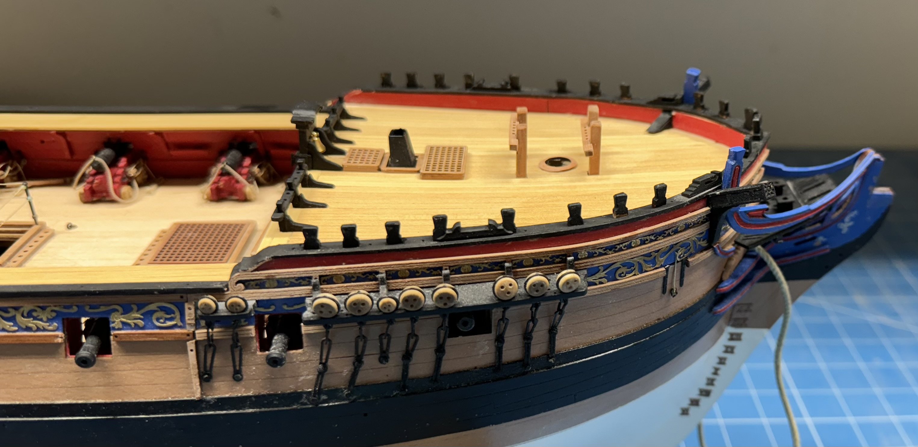
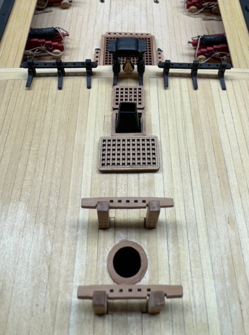
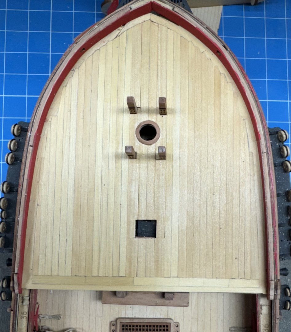
While "messing around" with the transom I also decided to work the bow "to completion" rather than moving forward to aft and back again. Seems better (to me) to get one end "done" before working on the other end. So here is the belfry and the forward pin rail in place and glued down. along with the hatch coamings and stove flue. I tried to get a picture lookung forwad from the waist but I can't seem to get the camera (iPhone) to cooperate. Have to save that for the next time i get my "big" camera out. I used epoxy to glue down the pin rail as there are rigging lines that belay here. Don't ask me how I know but it is never good to have a belay point come unglued during rigging.
- 422 replies
-
- 5
-
-
- Vanguard Models
- Sphinx
- (and 1 more)
-
Clearly (to me) I must have made another error somewhere, probably I did not get the sub deck or maple deck all the way down on the framing. That would seem to account for the inner bulwark pieces coming out higher than the existing bulwarks. I probably should have trimmed down the interior bulwark pieces rather than adding more material to the existing bulwarks - live and learn. Anyway I am working on a filler piece to bring the various pieces together at the stern. It is not what should be there but I think it will not be all that terrible looking.
- 422 replies
-
- 1
-
-
- Vanguard Models
- Sphinx
- (and 1 more)
-
Before I forget - IMHO it is much easier to cut out the openings for the cat heads BEFORE the cap rail is installed. I got so frustrated I took the cap rails off on both sides (and did some damage in the process) but deem it easier to fix that than spend several, hours trying to file away three layers of bulwark keeping it straight and square. Using a Xacto saw then a #11 blade took less than 10 minutes and made a much cleaner job.
- 422 replies
-
- 2
-
-
- Vanguard Models
- Sphinx
- (and 1 more)
-
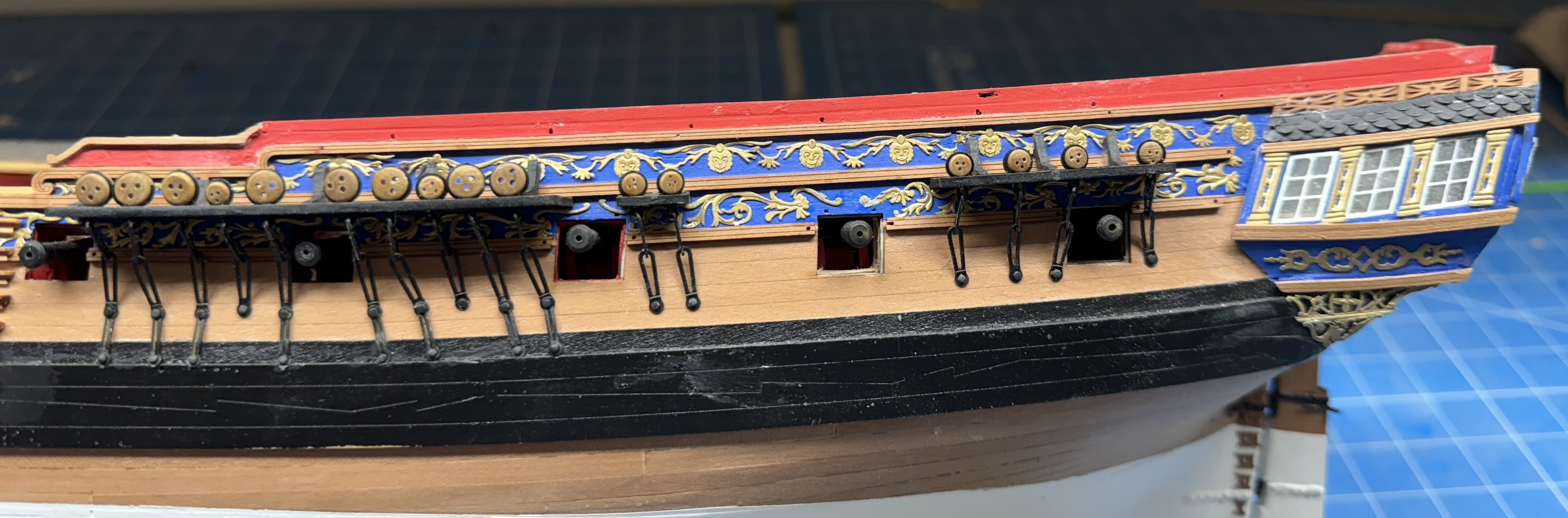
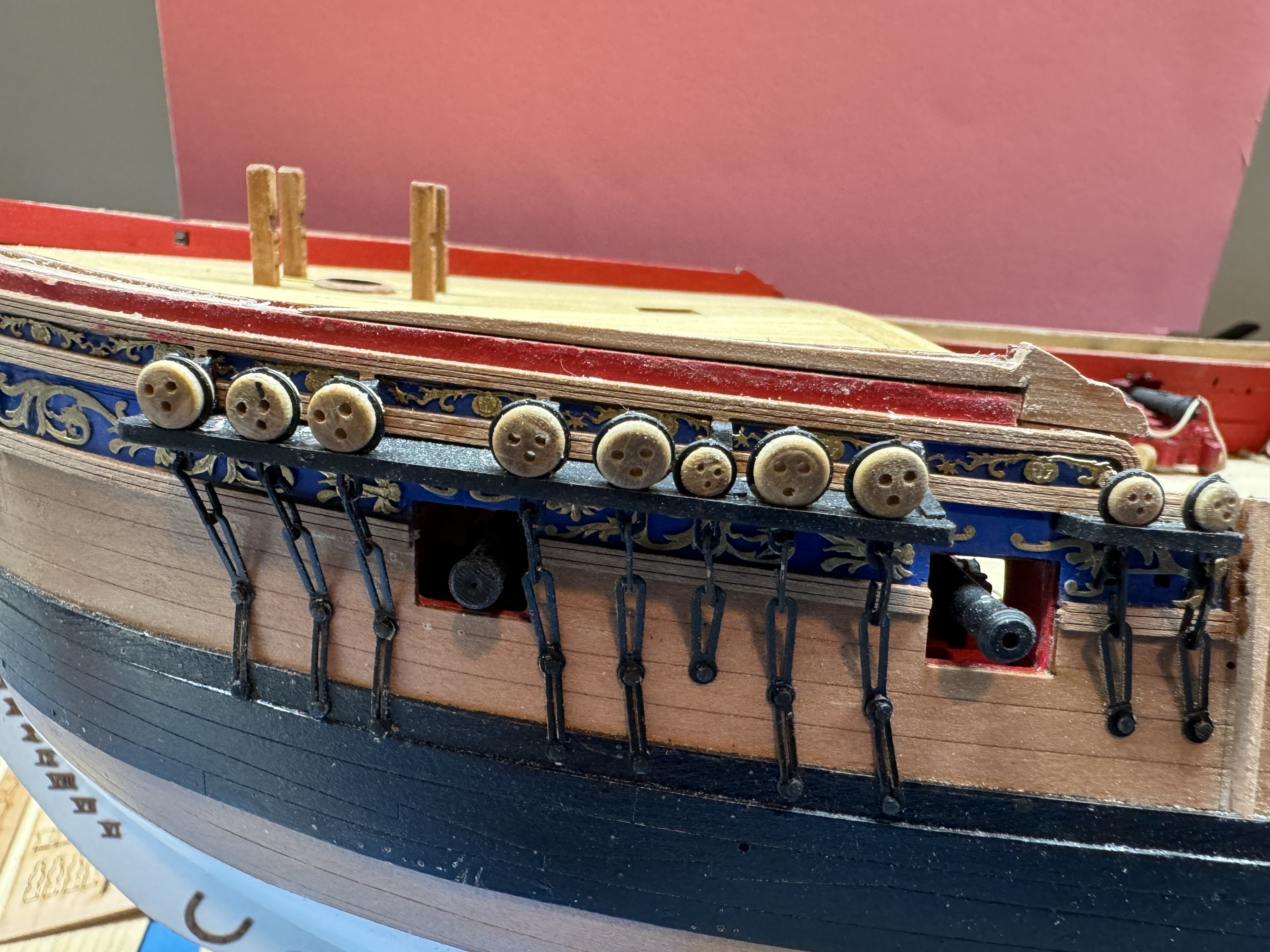
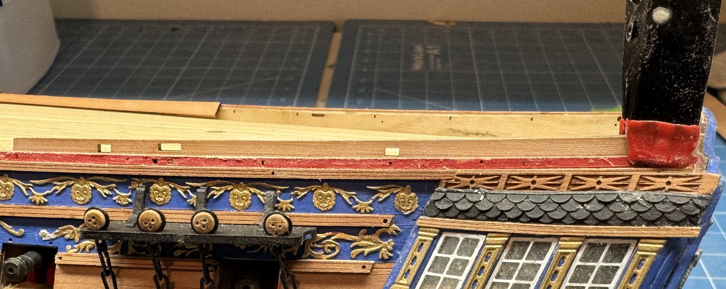
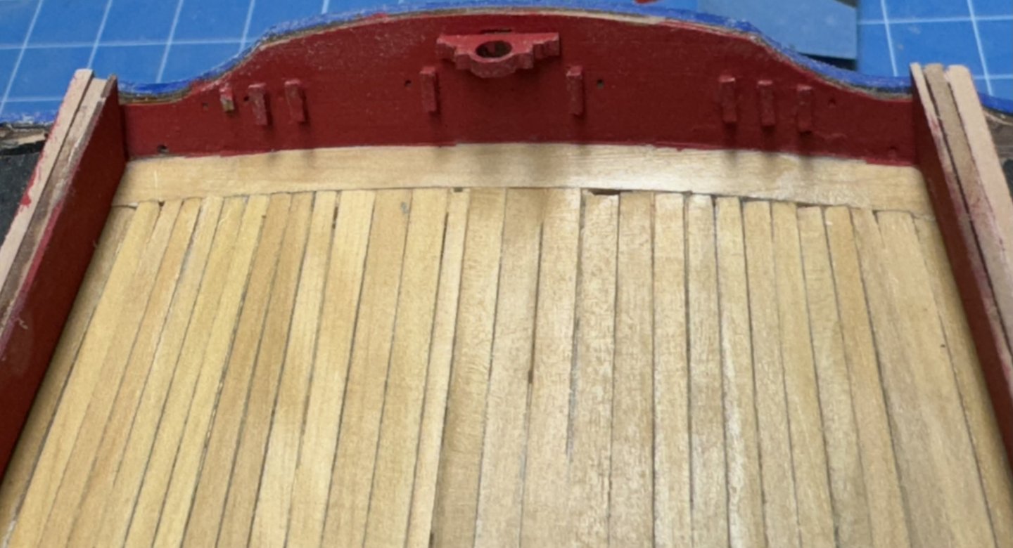
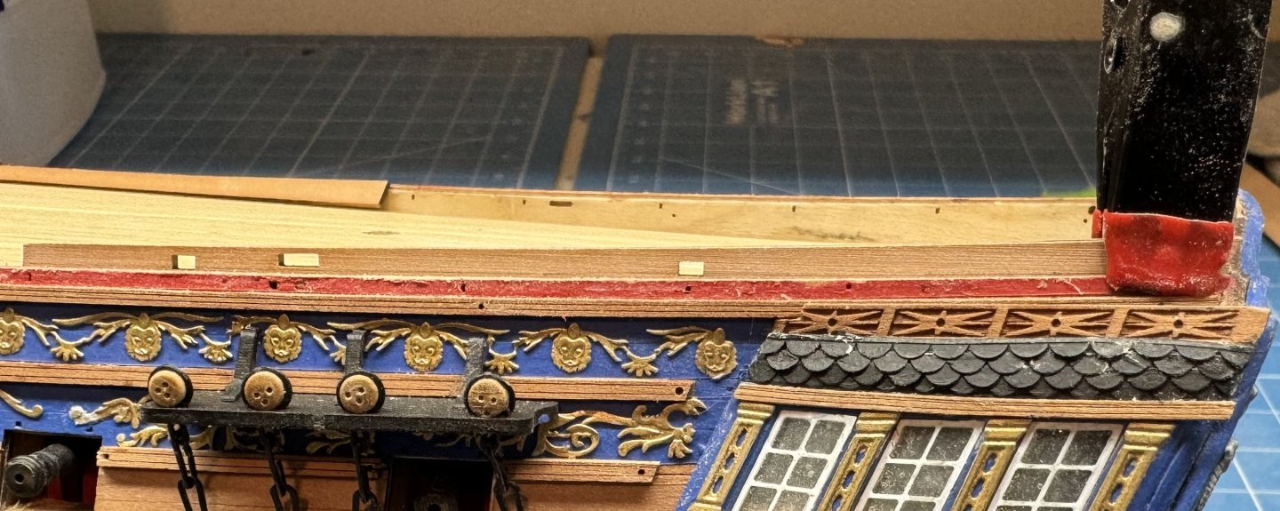
Some progress. I worked on getting the q-deck bulwarks up to the correct (at least for this model) height I was not as successful in filling in the seam between the pieces but at least they are even side to side (I think). Here is what they look like now. Sorry it is hard to tell one side from the other in this shot. I still have to add a divider to the sheave port above the mizzen channel, some more touch up painting and the seam is too obvious but that is after two sets of filler so I will adhere to Adm Groshkov's (Head of Soviet Navy in the 80's) saying "better is the enemy of good enough". I added the cleats to the transom (I just noticed I broke one off already 🤐) and painted it red. I planked the gangway decks and added the (previously assembled) ladders to the gun deck. I have the steps going from the q-deck to the gangway "in assembly" using boxwood for the step. And now the next "problem". It appears that now the entire stern is too low. I am not sure how these are all supposed to fit together (I better make an exhaustive search of the supplemental drawings - the instruction manual is pretty light on this (IMHO)). Here is the stern now. The bulwarks stick up about 4mm (at least it is the same on both sides). Considering my options at this point. It may come down to making a "transom extension" to fair in the bulwarks to the transom. Sounds like almost as much fun as fashioning the bulwark extension although at least everything there was flat and straight lines.

- 422 replies
-
- 2
-
-
- Vanguard Models
- Sphinx
- (and 1 more)
-
Forward area with "scabbed in" piece filled and painted. I checked the cross hull heights and they are all within .3mm of each other so I judge that to be "close enough". Now to the aft "issues".
- 422 replies
-
- 7
-
-
- Vanguard Models
- Sphinx
- (and 1 more)
-
Back at the bow I got a piece "scabbed in" to even out the two sides. I will add some filler and try and hide the seam. I probably will not make more two attempts at filling in the seam. It is after all under the cap rail and mostly behind the fore shrouds.
- 422 replies
-
- 5
-
-
- Vanguard Models
- Sphinx
- (and 1 more)
-
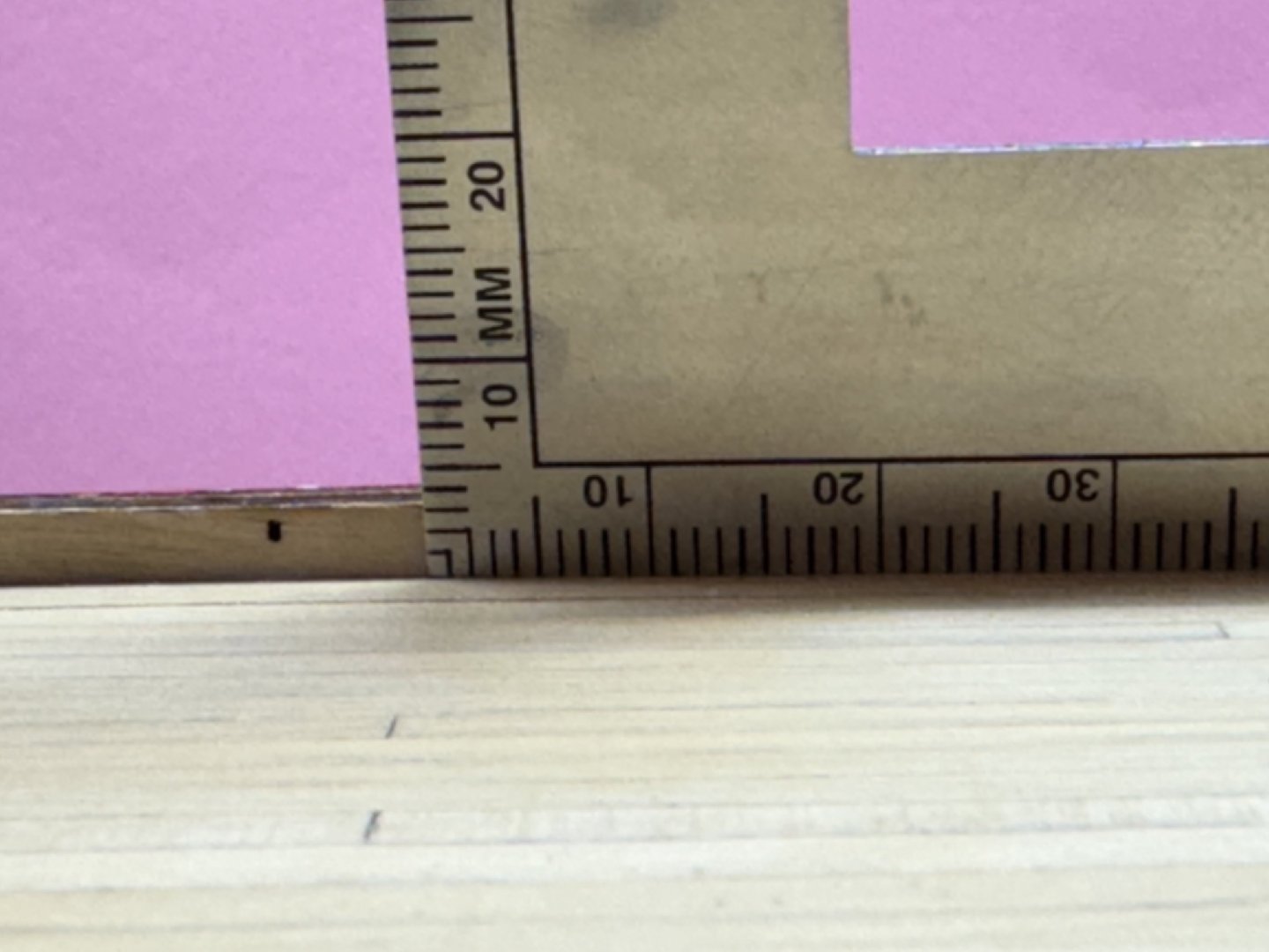
Some research appears to be in order. Plans (Sheet 10 in board profile) shows that the aft end of the q-deck bulwark should be 8.5mm above the deck. And at the upper capstan (the easiest place to measure since that little blip in the bulwark is not shown on the inboard profile) the bulwark is 3mm above the deck. Measurements on the model show the starboard side aft is currently at 7mm at the lower inner layer. And forward the starboard side is maybe just a bit high (?) at 3.5mm but really only 3mm if the outer and inner bulwarks were trimmed to match (which they have to be to evenly support the cap rail). And the port side aft is at 5mm. And port side forward is at 2.5mm or probably 2mm when bulwarks are evened. So on the starboard side I need "addition" 1.5mm high at the aft end and tapering down to zero even with the upper capstan . On the port side a similar addition 3.5mm high aft and 1mm even with the capstan the tapering to zero at the forward end. Now on to creating the "piece that binds" so to speak.


- 422 replies
-
- 3
-
-
- Vanguard Models
- Sphinx
- (and 1 more)
-
And I thought I had an "alignment" problem at the forecastle - much worse, approx 5mm too low at the extreme aft end if the external and internal bulwarks are supposed to line up - and everything I have says they should. And back here it is not just the .8mm external layer that is too low, the entire side (approx 2mm thick) is too low. Back to the drawing board to figure out how to "fix" this - clearly I have to add an additional piece (approx 2mm thick) on top of the existing bulwark. Same problem on the other side just not quite so far off, 3mm or so at the extreme aft end. I am going to put the WOP on the q-deck and go try and "fix" this problem on the bow (port side only) and hopefully learn something about how to tackle the stern.
- 422 replies
-
- 2
-
-
- Vanguard Models
- Sphinx
- (and 1 more)
-
Quarterdeck planking completed. Obviously some trimming, sanding and WOP yet to be accomplished. Here is the forecastle after three coats of WOP Getting close to adding the topside "details".

- 422 replies
-
- 6
-
-

-
- Vanguard Models
- Sphinx
- (and 1 more)
-
Thanks Ronald - that was my choice as well. I seem to remember painting the joint between the inner and out planking with dilute PVA and getting the existing part off without doing more harm seems unlikely. Still working the q-deck planking. Here i have the all the edges completed and the "king plank" (actually two planks) down the centerline. is poised awaiting some detailed measurement to ensure it is actually on the centerline.
- 422 replies
-
- 5
-
-
- Vanguard Models
- Sphinx
- (and 1 more)
-
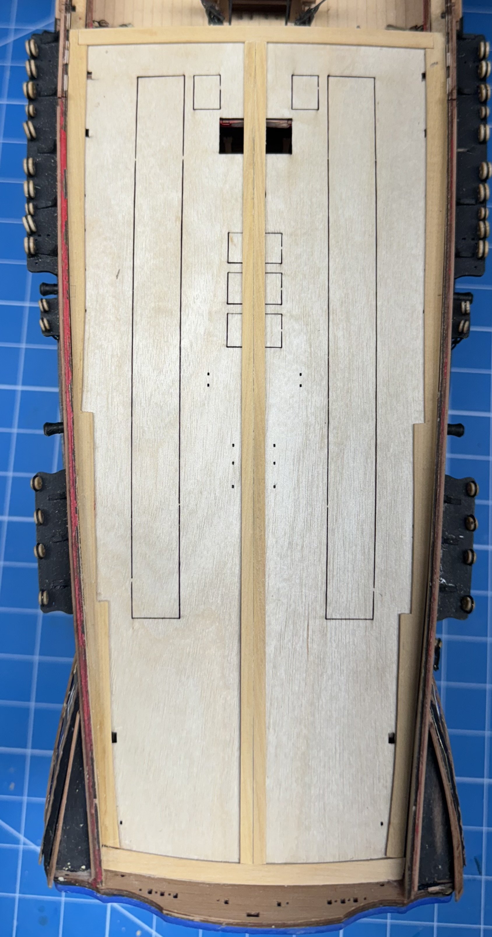
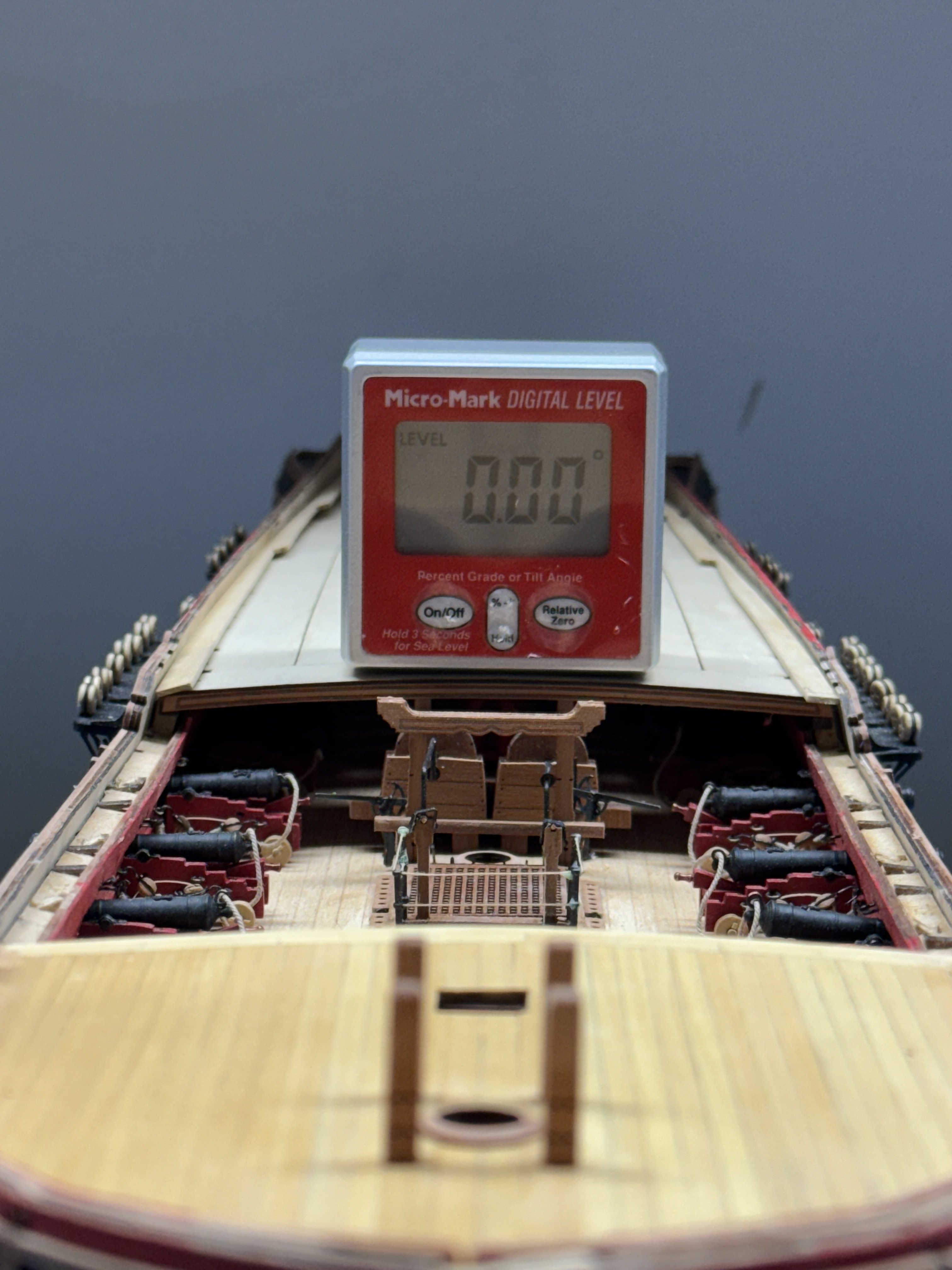
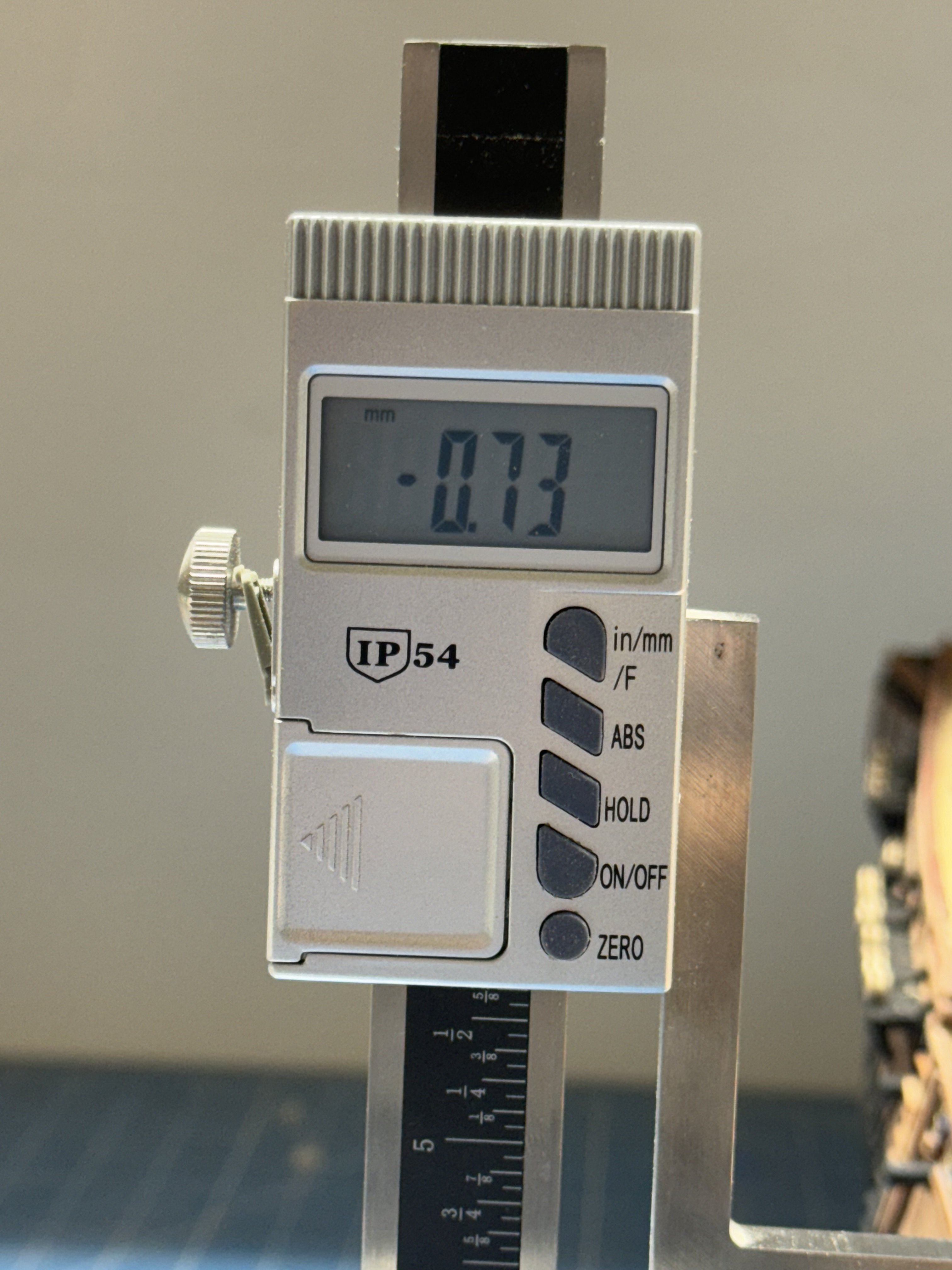
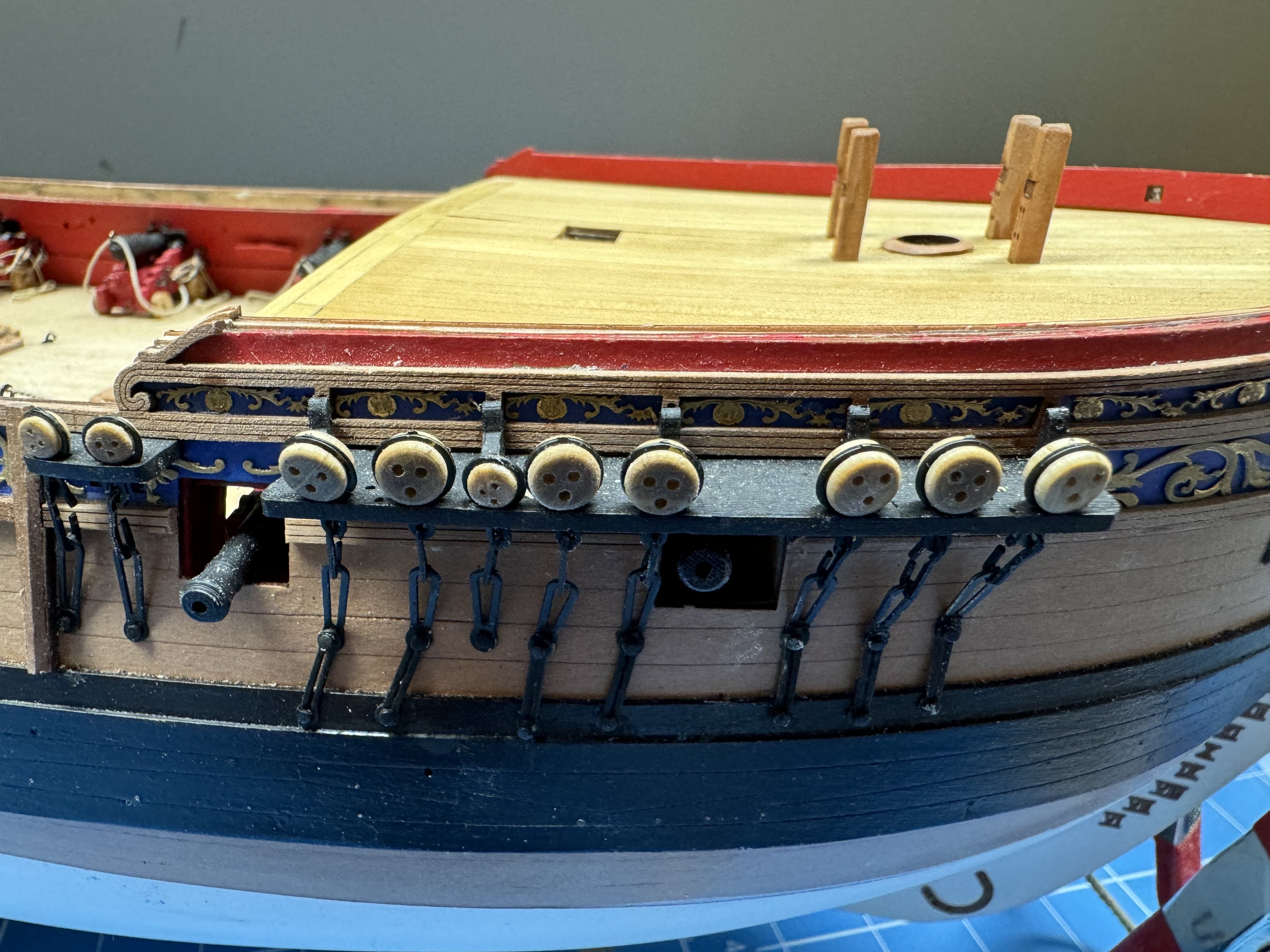
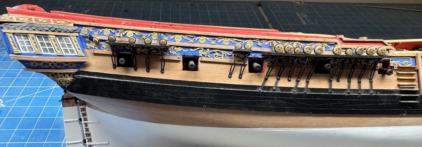
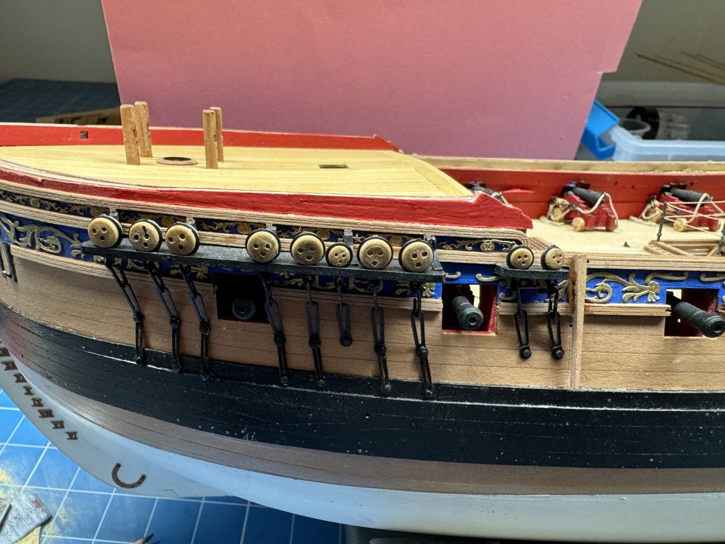
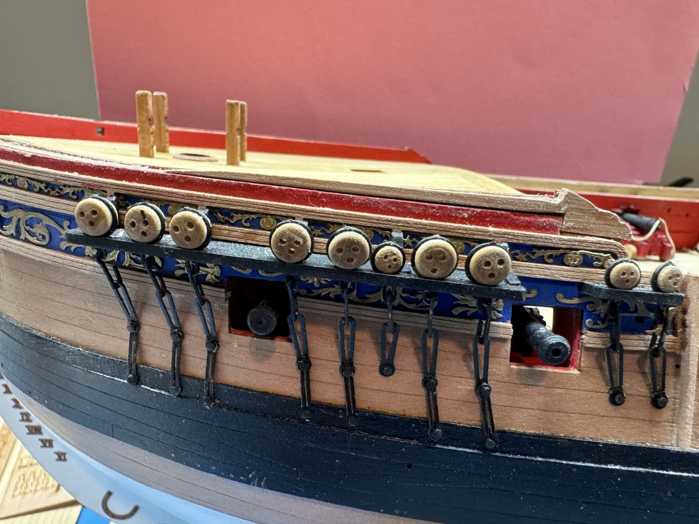
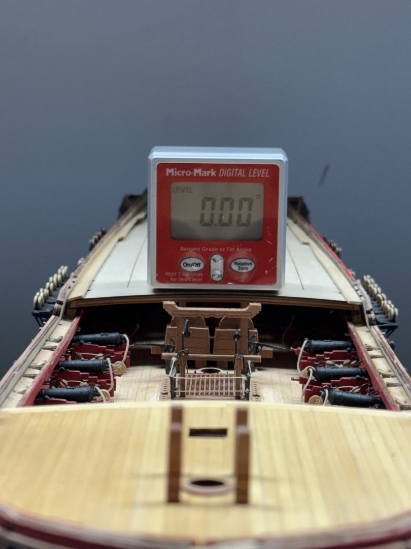
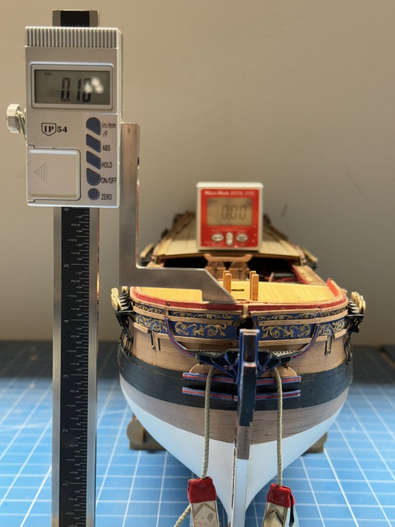
I have known this day was coming but it did not make any sense (to me) to address it before now. I got the outer "skin" (the .08mm thick, engraved pear) on the starboard side a little too low, especially near the back of the forecastle. It is pretty obvious as you can see below. Port side: Starboard side: I wondered if it was just the outer skin or was there some underlying problem. So I set out to measure the bulwark height at the bow. I put the hull in the cradle and used my handy-dandy electronic level to at least attempt to get the hull level. I put the level as close to the center of the front of the q-deck and low and behold it came up level without me having to touch anything. So far so good. Then I took the height measuring "device" and zeroed it resting on the aft end of the starboard bulwark just forward of the little "ear" that sticks up. Then I moved it to the port side and found that at the aft end the port side is .073mm lower than the starboard. Then I checked the bow Port side is .1mm higher. From this I conclude that there is no "underlying" problem, I just got the starboard side "skin" on too low. somehow (most likely inadequate attention to detail) Now what to do about it? I think I have four options: 1. Ignore it, no one will notice, especially with the cap rail and blizzard of rigging above and shrouds/ratlines in front (mostly). 2. Just paint the part of the inner bulwark that shows red. 3. Remove the entire part of the skin currently showing and replace it with a new .8mm thick section that matches the height of the inner bulwark and paint red. 4. Add a piece of .8mm pear above the existing to the height of the inner bulwark and paint red. Anyone see another path? I am going to plank the q-deck while I consider these options and any others that are provided.


- 422 replies
-
- 2
-
-
- Vanguard Models
- Sphinx
- (and 1 more)
-
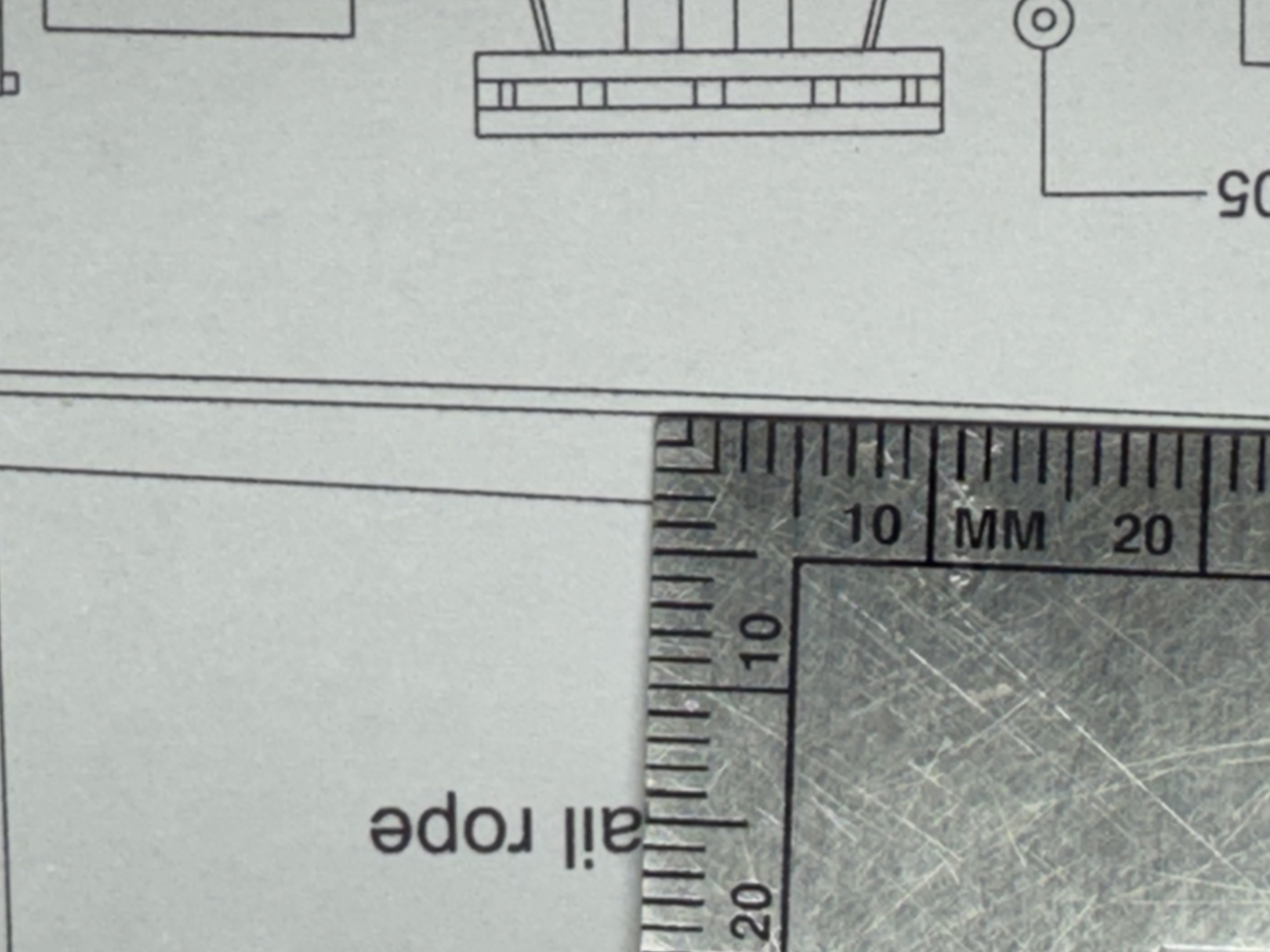
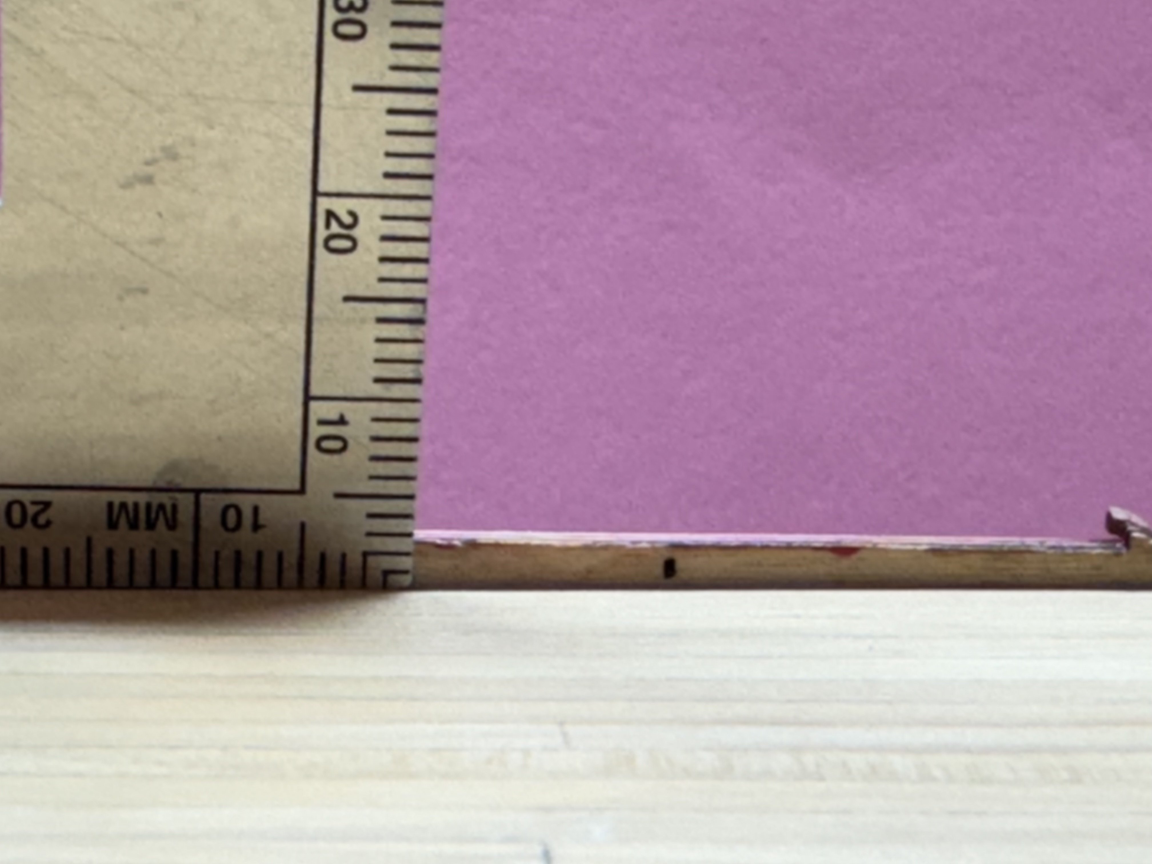
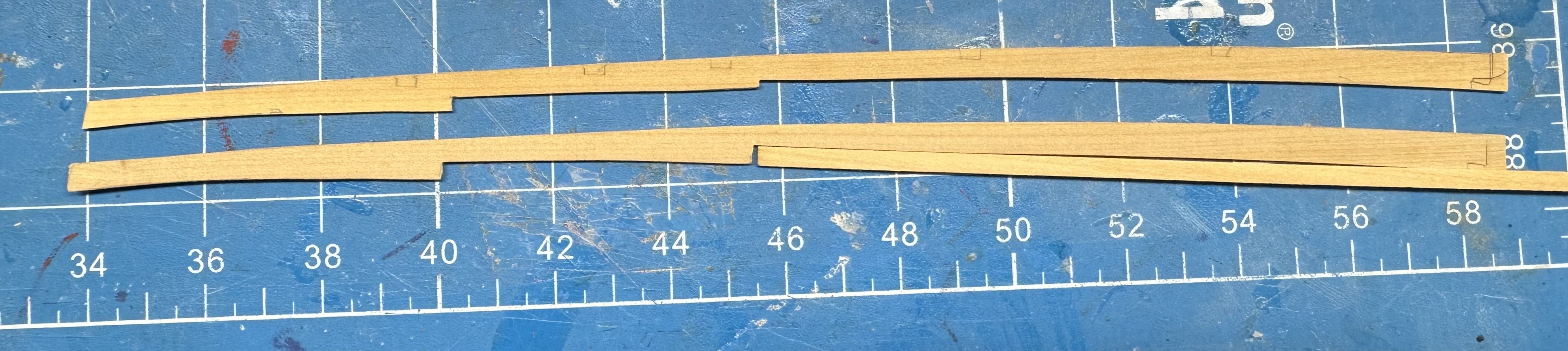
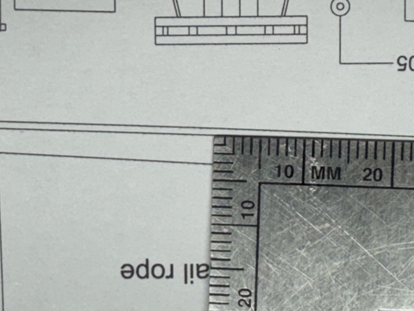
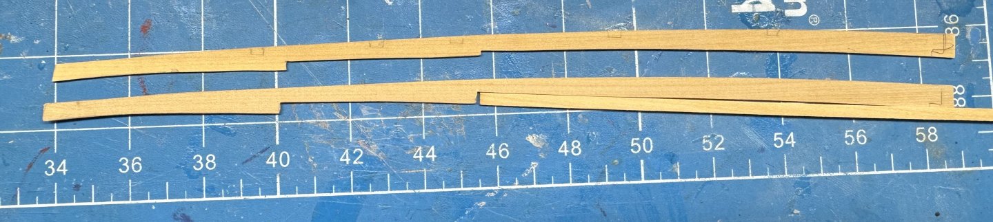
My boxwood shipment arrived and a quick check of the dimensions look good 3/64 X 1/8" X 15". Having learned my lesson on the forecastle I took the outboard planks which I had copied from the equivalent plank on the maple deck and modified them so that a 1/8" wide plank will fit. The top plank is what I copied from the maple deck. Below is the modified plank that a 1/8" wide plank will "fit" in the open "slot". Have to modify the other outboard plank, pick some matching boxwood strips and get on with planking the q-deck.
- 422 replies
-
- 2
-
-
- Vanguard Models
- Sphinx
- (and 1 more)
-
That would certainly make these easier for the Captain. Did a 6th rate have three LTs or just two? Three could probably share the port side cabin since one is presumably always on watch or on deck.
-
Yes, it looks great. Where is the captain's hammock going to go? Looks like the cabin would have to be rearranged for sleeping or the hammock will block the entrance to one of the q-galleries. Maybe they hung the hammock athwartships above the locker (or whatever its is called) at the transom - not the current custom in the USN (almost all bunks run fore/aft).
-
Ronald - I also noted the varying dimensions on the hull planking. Next time (Indy) I am going to find the thinnest plank and use the thickness sander to get them all as close to that thickness as I can. Different widths are easier to deal with and many of the planks are not a constant width anyway. Thickness differences can really complicate trying to sand the hull smooth. Although by the appearance of your hull you overcame (and then some) whatever eccentricities the hull planking threw at you. At least there is a "deck planking plan" on the maple decking although I think it used 3.5mm planks - at least on the forecastle. brunnels - this is not my "first rodeo" planking decks. In fact this is the first time I had a "pre-planked" deck to use which I did on the gun deck - too many openings for my taste but the q-deck and forecastle are more my speed.
- 422 replies
-
- 2
-
-
- Vanguard Models
- Sphinx
- (and 1 more)
-
Thanks Ronald 😀 I would not recommend the approach I took unless you have the ability to generate planks of essentially any width. I started planking from the bitt posts out to the edges where I had the "pre-cut" nibbling strake. That went okay until I got close to the edge where I needed to create planks with widths that would allow them to fit within what had become "per-determined" (by the planks already in place) dimensions. Without a miniature (4") table saw that would have meant a good deal of sanding and shaping. Plus I have to create some planks wider than what was my standard here (1/8"). Between the bitt posts was even more challenging because of having to plank around the stove flue opening and the bitt posts. Again wider than "standard" planks were necessary. I have more boxwood coming tomorrow for the quarterdeck. Hopefully I can get a more consistent color match there. I did notice that on the maple deck there is at least one plank (third one in on starboard side) that runs all the way from one end to the other without a joint. That would be a really long plank (approx 50')
- 422 replies
-
- 1
-
-
- Vanguard Models
- Sphinx
- (and 1 more)
-
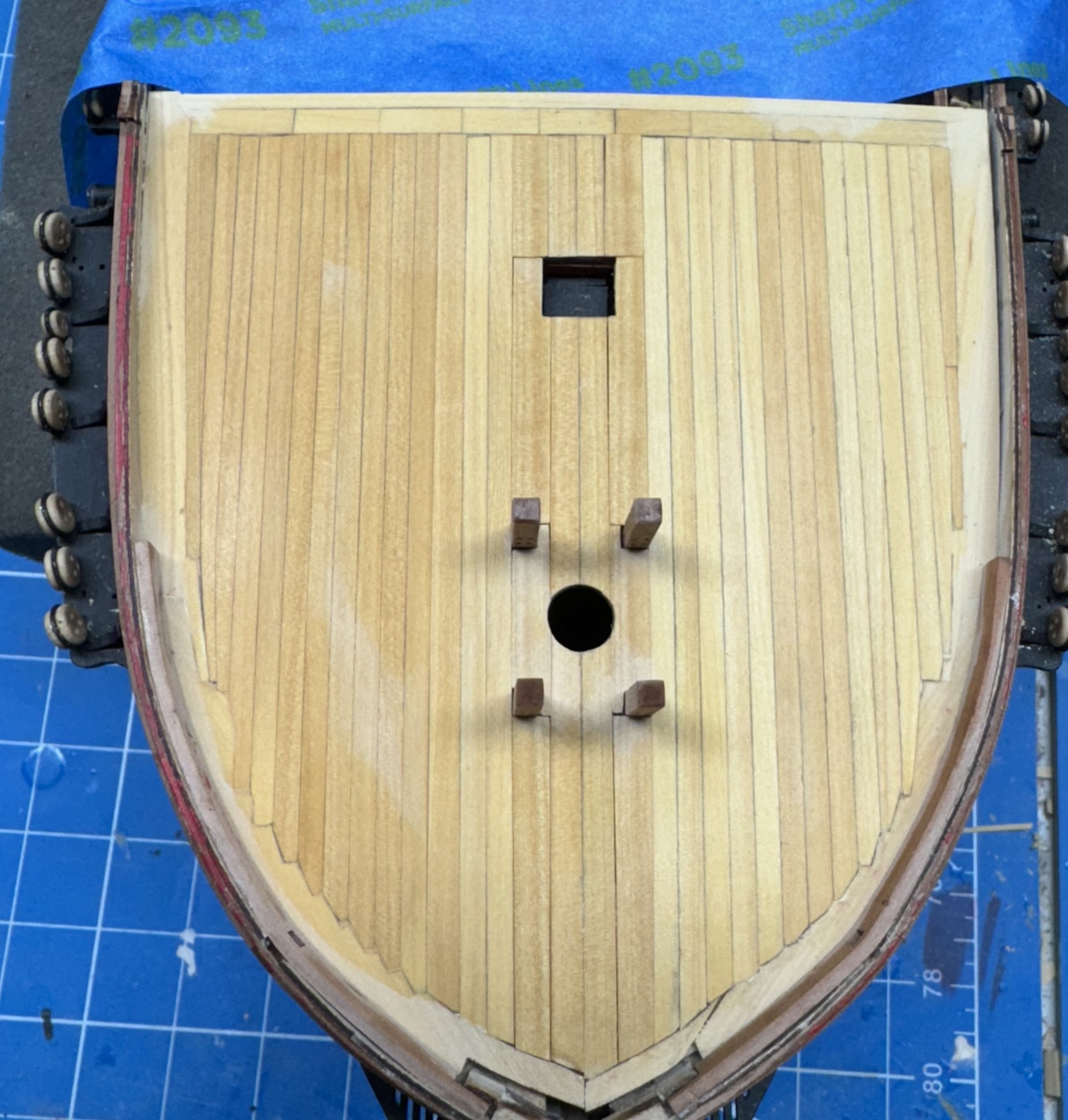
A big jigsaw puzzle indeed. The forecastle planked over in box wood. Not the greatest job of color matching (although there is still a bit of clean-up water on the wood in places) but I find it difficult to discern the various shades of boxwood unless it is obvious to the casual observer. I did not bother to plank around the hatches as they just sat on the maple deck - with the stove flue as I guide I can get the hatches located without the deck marking. There are a single piece after all. A few coats of WOP and I can add the furniture, what there is of it. I also need to figure out what to do about the very front - I apparently did not get the various parts together per the instructions. need a "filler" piece of some kind.

- 422 replies
-
- 6
-
-
- Vanguard Models
- Sphinx
- (and 1 more)
-
Ronald - what are you using for adhesive on the decking? I am about to start the forecastle decking and am torn between carpenter and PVA. I might have been tempted to plank over hatches rather than plank around them (carefully marking where thew go of course). You won't really be able to tell, especially if you paint the planks black under the hatch grating.
-
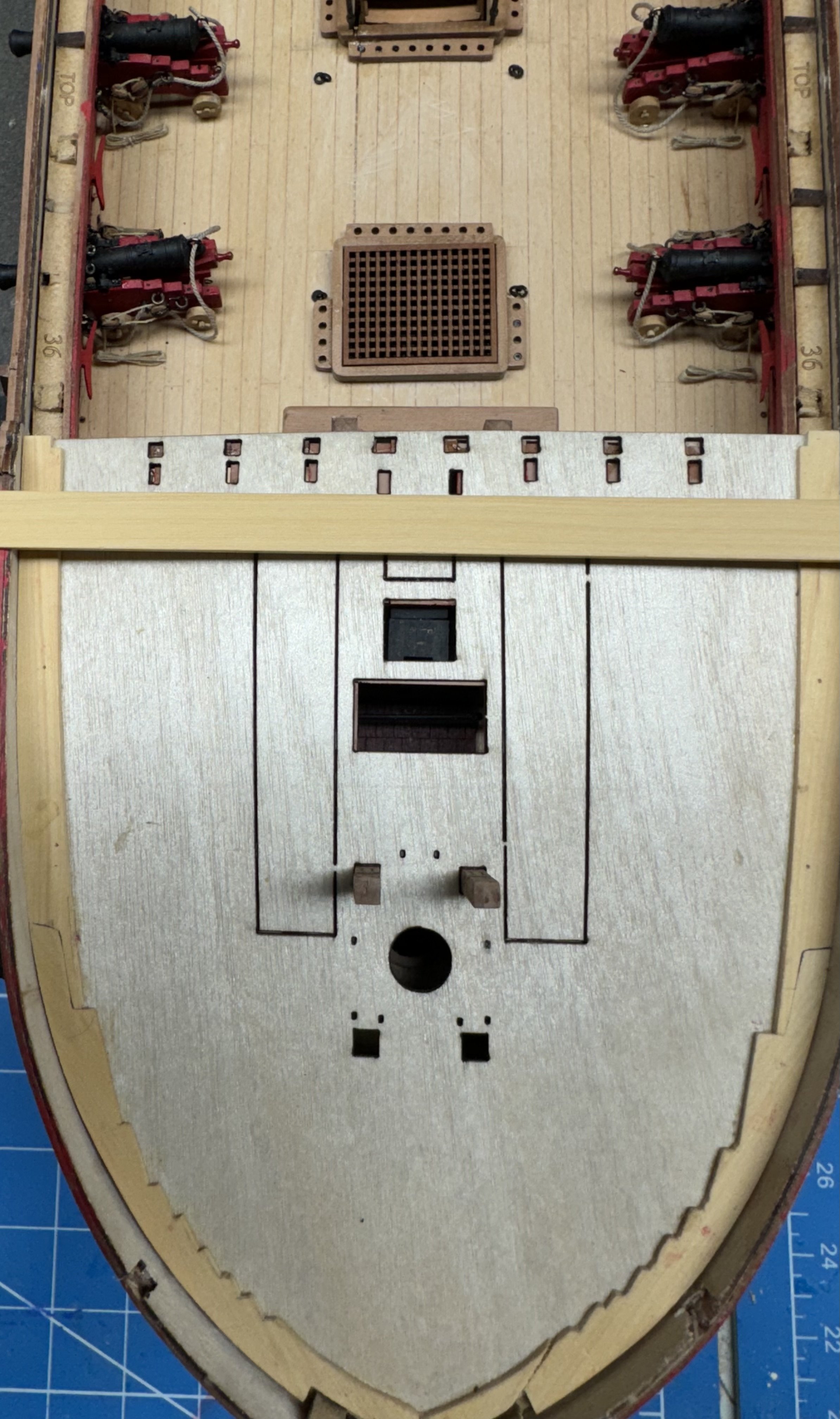
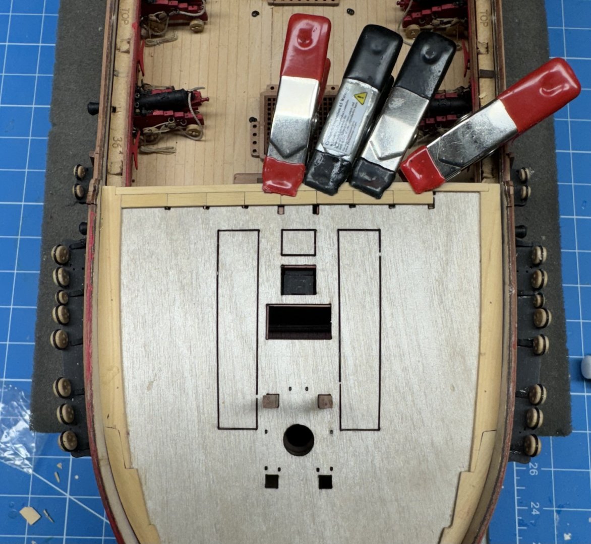
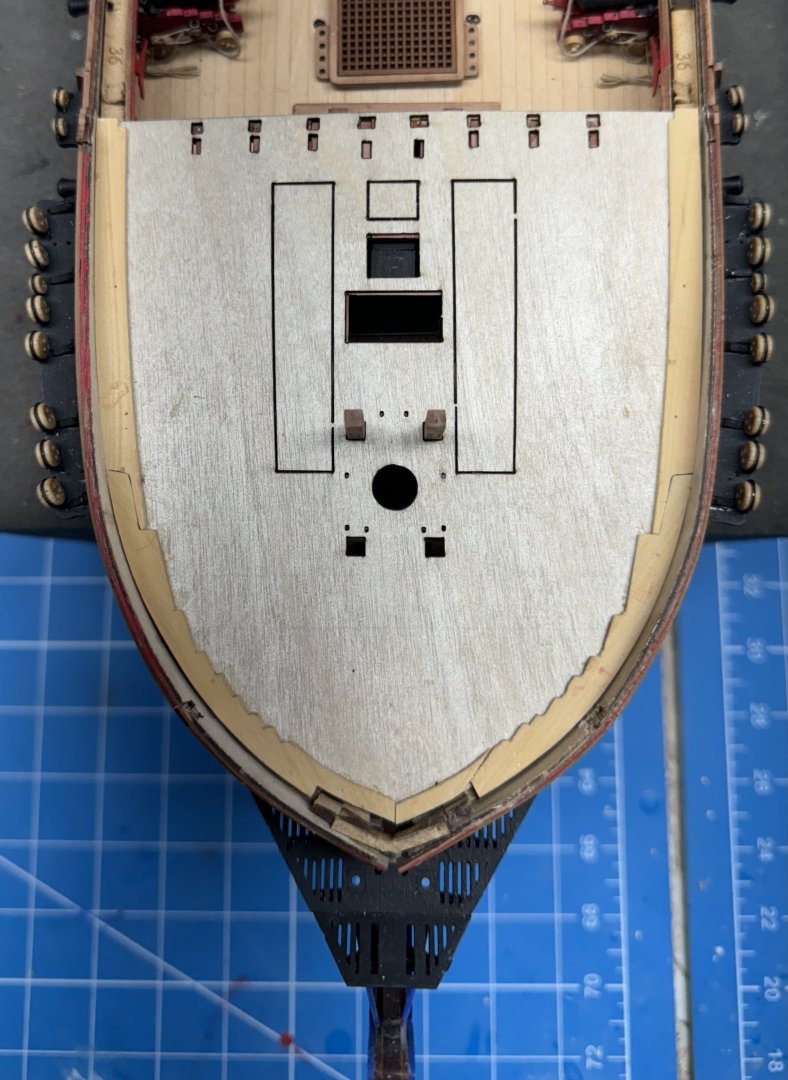
Having considered the "problem" again I changed tactics (slightly). Instead of cutting pieces that would cover the entire area between the "tabs" I cut a narrow piece to fit across the very aft edge of the deck. And then cut pieces to cover the area between the tabs so that the seam between each set of pieces would mark the center of the "tab" and thus where the railing/belfry supports should land give or take a small bit - since the railing sections are already made up with fixed distances between the posts I can't be too picky about where all three posts fall as long as it "looks good". Here is the deck with the penultimate pieces glued in place. I am waiting until they are fixed in place before cutting the final piece. Trust me trying to keep more than 3 or 4 of those small pieces in place while you measure for the next one can be a challenge. From here I am considering running pieces along the outside of the posts (after adding the other two) and then working towards the bulwark. Planking the inner section may require planks of varying width so as not to complicate things with "notched planks". I also need to keep track of where the markings for eyebolts are located.
- 422 replies
-
- 5
-
-
- Vanguard Models
- Sphinx
- (and 1 more)
-
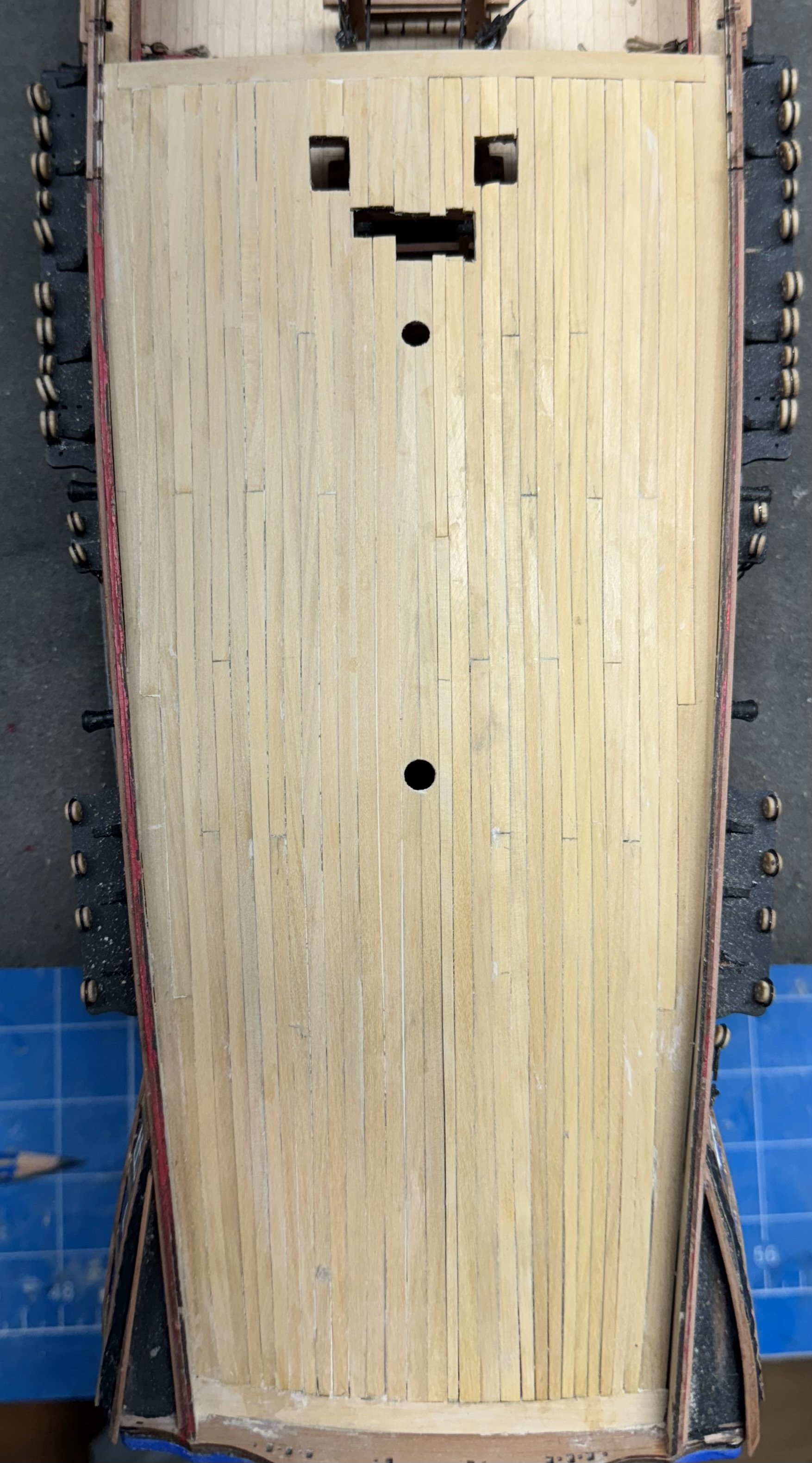
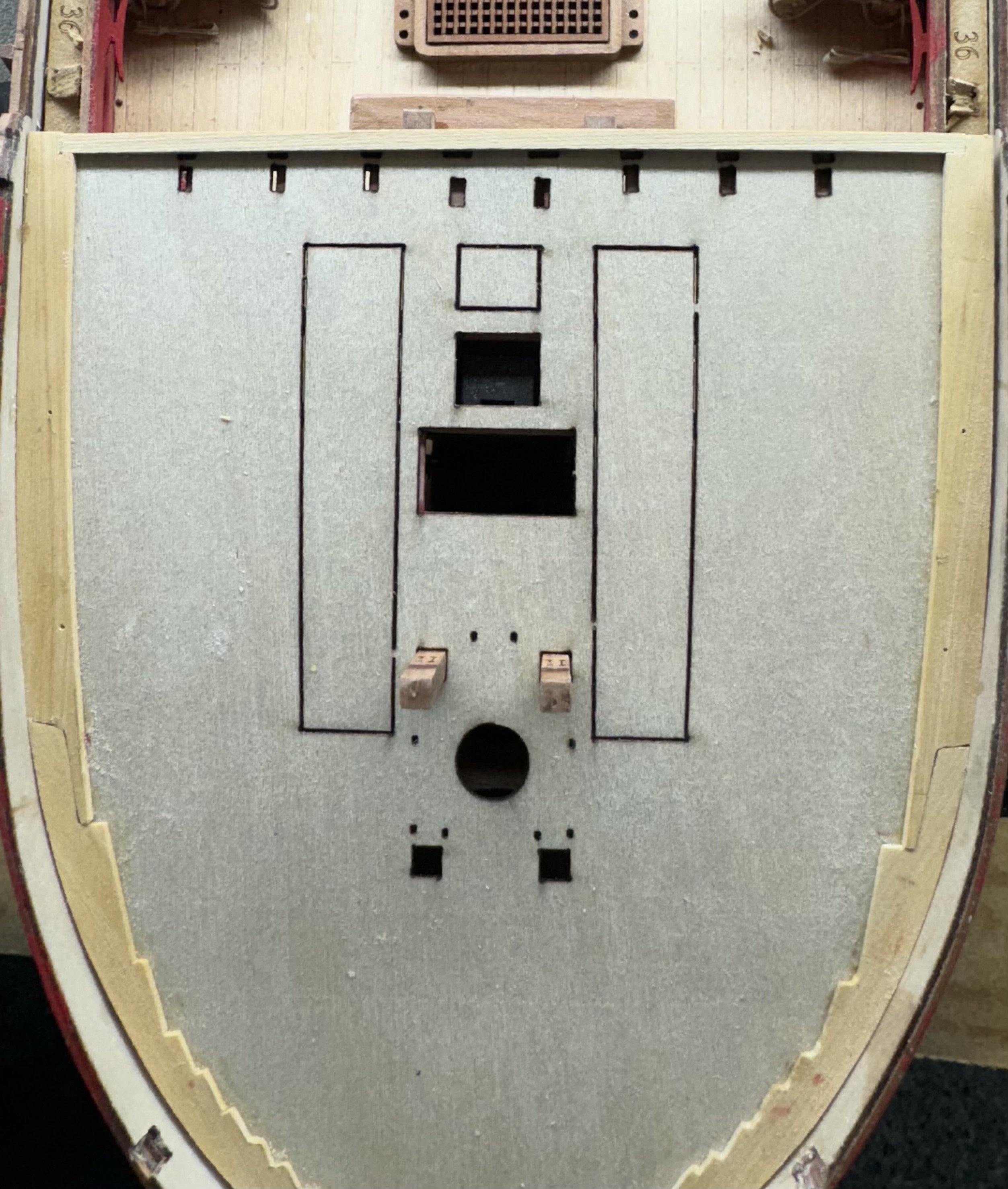
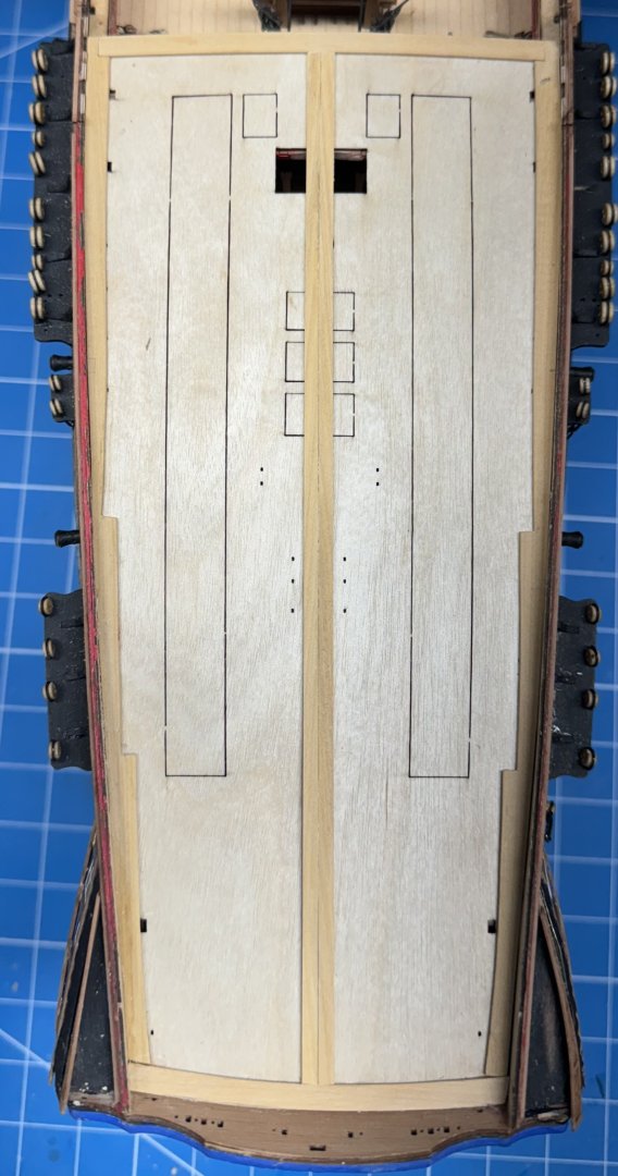
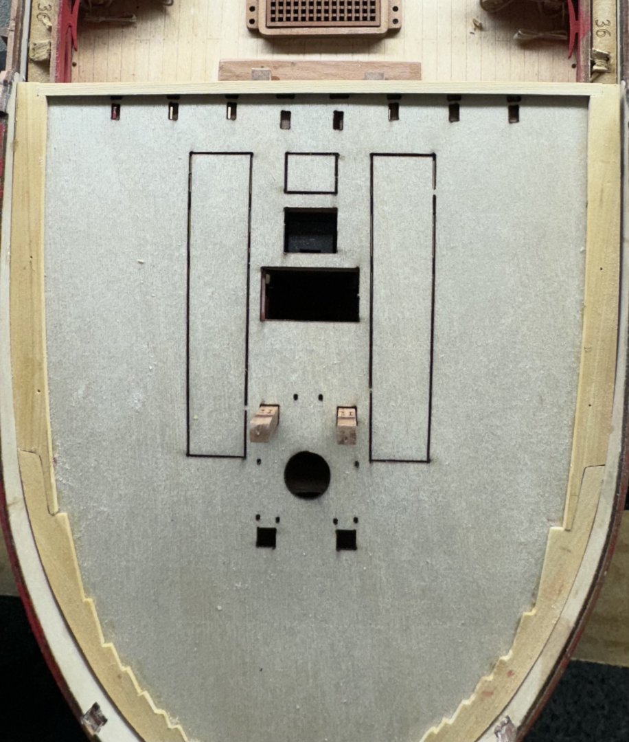
Ronald - I am pretty much committed to this approach, at least for now. I will look at the BE Sphinx build as I am not familiar with what he did but may use it on my Indy build coming "soon" after i finish Sphinx. I will have to "pay attention" to joints at the front of each plank where they meet the waterway or whatever the outboard plank is called in this case. With the planking scheme established at the bulwarks it is time to figure out what to do at the back (stern end). This is here I think the extra deck thickness is going to be an issue. If you just use the maple deck then the belfry and railing sit flush with the top of that deck (assuming you get the tabs on the supports into the slots in the deck. My first thought was to cut a series of small pieces of boxwood to fit in between the areas where the railing/belfry will go. However doing that would put them about 1mm lower than would be the case with just the maple deck unless I fill in the holes in the ply deck first. Given that the railing is a belaying point I do not want to do anything to reduce the clearance between the deck and the railing as it will be hard enough to belay a line to the railing with the "standard" spacing. So I cut a piece of boxwood as wide as the two sets of slots. My first thought was to cut and fit this between the two waterways, mark where the railing/belfry go and "move on". I would have to file the tabs off the supports and probably pin the railing legs to the deck as I have little faith in just a glue joint for items under rigging tension. Then I thought maybe I could cut pieces of the plank so the joint falls in the middle of each set of slots. That way no marking is required and it should be easier to locate the belfry/railing when the time comes. That is how I think (subject to unforeseen "difficulties") I am going to proceed.

- 422 replies
-
- 7
-
-
- Vanguard Models
- Sphinx
- (and 1 more)
-
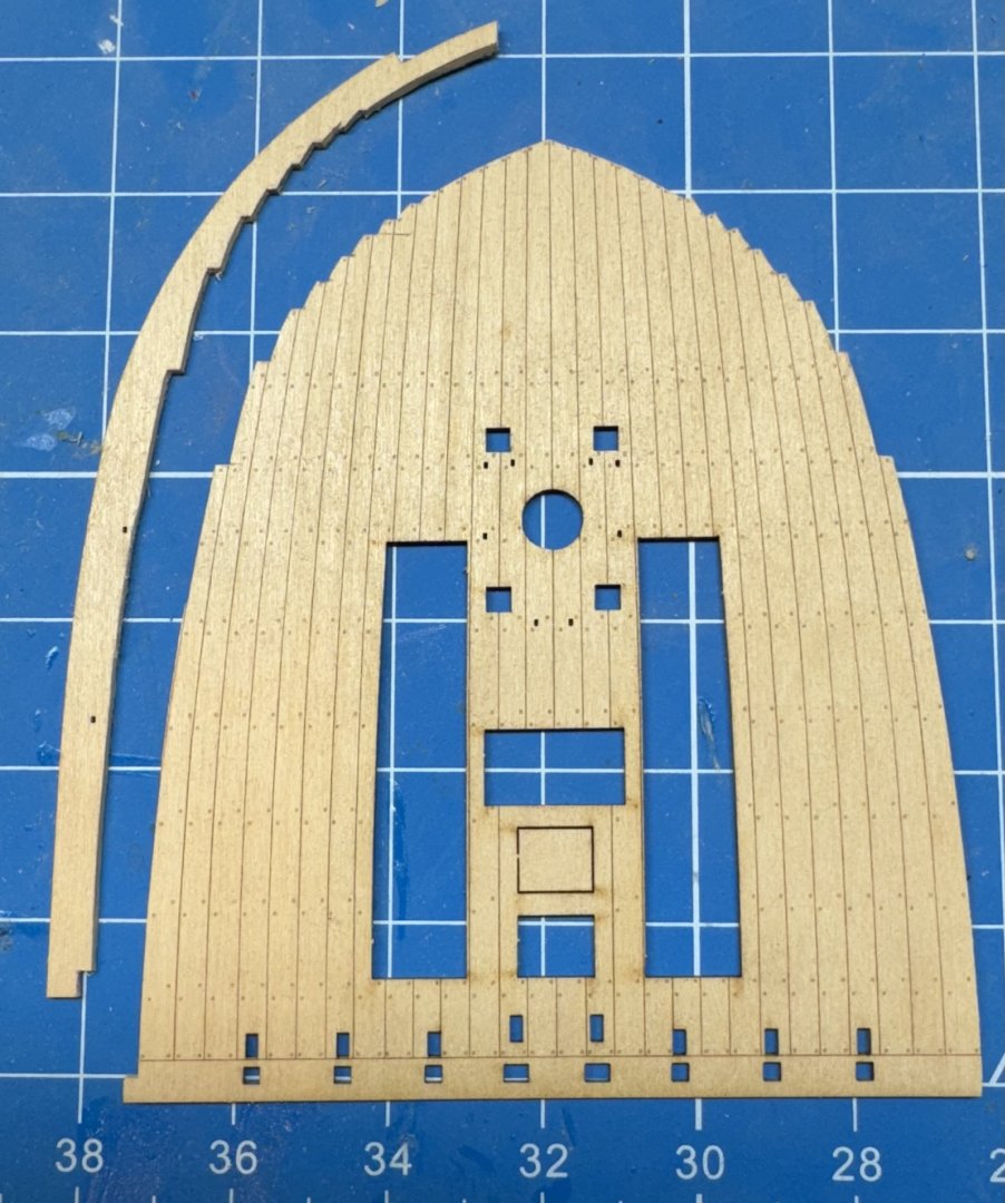
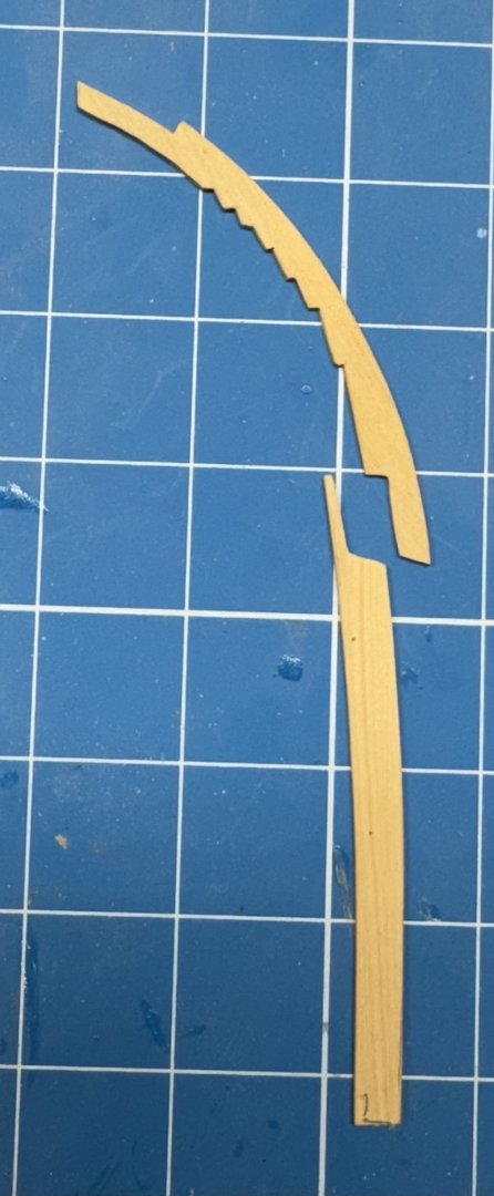
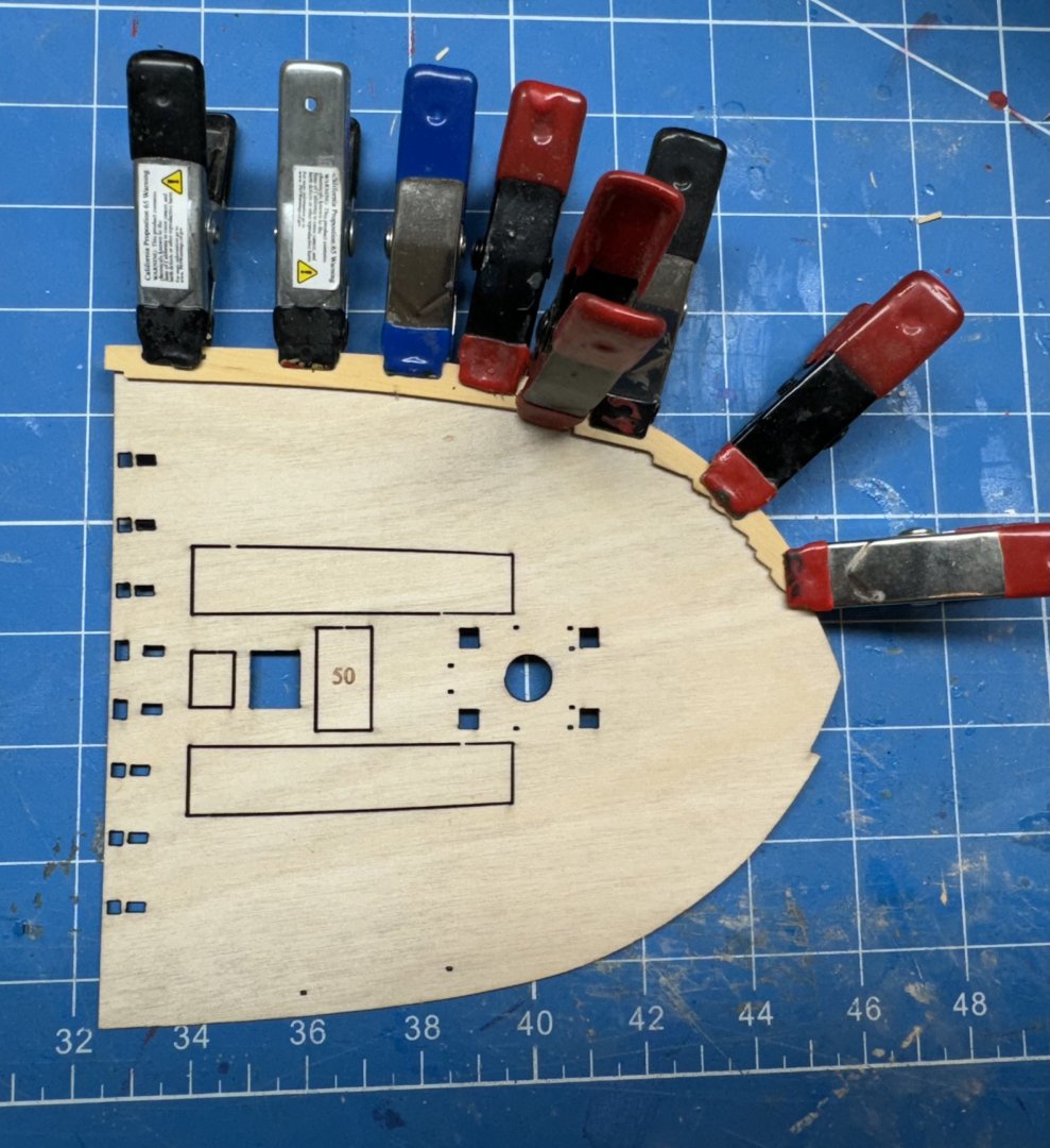
How to approach planking the forecastle?? My experience with deck planking usually starts at the center with the "king" plank(s) and using constant width planks move outward until you hit the bulwark and then nibble the ends of the planks until you have filled all the area. Looking at the maple deck and its planking scheme it appears that many of the planks were tapered as they neared the bow and ended at a wider, continuous "nibbing" plank at the bulwark. I decided to try and replicate the maple planking scheme (less the trenails). To affect this I carefully cut the nibbing strake from the maple deck - It was pretty easy to follow the engraved line, but not that easy since I had to do it twice to get an acceptable "sample". That piece is also quite fragile so I decided to split it into two parts with my approximation of a scarf joint. These are the starboard side pieces now in boxwood. I had trimmed the plywood deck to fit but thought I should glue the nibbing starkes to the deck and then the deck to the hull (after installing the fore jeer bitts - I almost forgot). Here is the ply deck with the port side nibbing strake glued and clamped. Starboard side next then the deck goes on the hull. The one nagging worry is that now I will have a deck twice (maybe a bit more than twice) as thick as if I had just put the maple deck down. We are only talking about 1mm or so but....
- 422 replies
-
- 5
-
-
- Vanguard Models
- Sphinx
- (and 1 more)
-
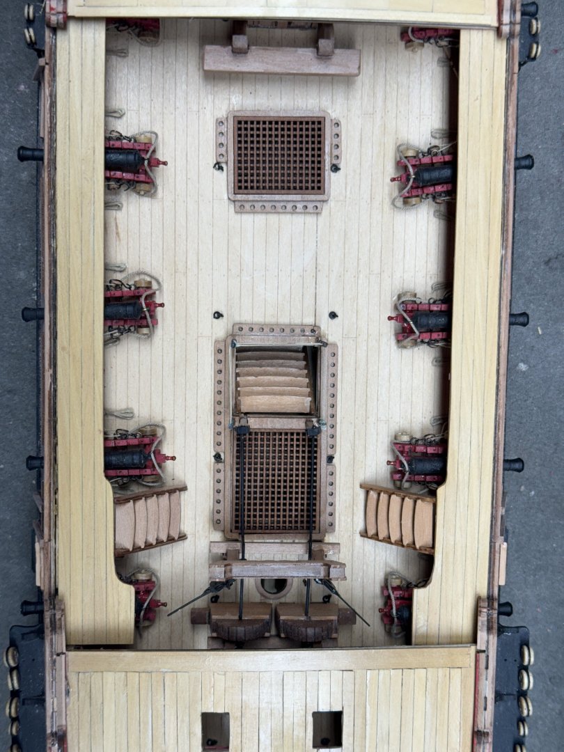
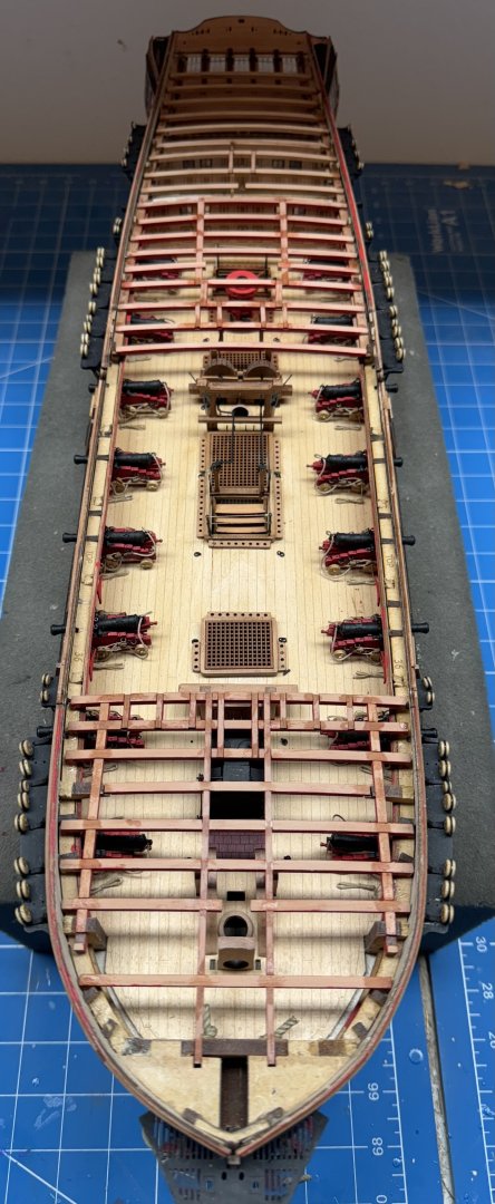
Thanks Brunnels - it will go slower now as i have decided to try and plank the forecastle and q-deck in boxwood. Forecastle and q-deck beams and carlings in place. I have decided to completely plank the forecastle and q-deck - no "inspection ports". I intend to full rig the model which will make seeing much through the openings very hard so I will (sadly) cover up all the details inside the cabin areas except what can be seen through the gun ports or stern windows. With the three ship's boats in the waist and the blizzard of rigging above there will be poor visibility of what is on the gun deck so I am not sure why I spent all that time rigging the cannon. Oh well, it is a "hobby" after all. Anyway I am waiting for some boxwood strips and planks I ordered to plank the "upper" decks which will be much more visible than the gun deck. In the meantime I am trying to replicate the waterway on the forecastle using some boxwood planks I have "on hand".
- 422 replies
-
- 4
-
-
- Vanguard Models
- Sphinx
- (and 1 more)