


EdT
-
Posts
2,210 -
Joined
-
Last visited
Content Type
Profiles
Forums
Gallery
Events
Posts posted by EdT
-
-
1:60 HMS Naiad 1797
Part 22 – Structural Plates
Posted 11/15/10
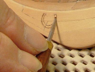
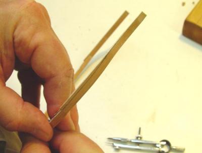
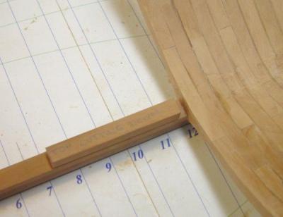
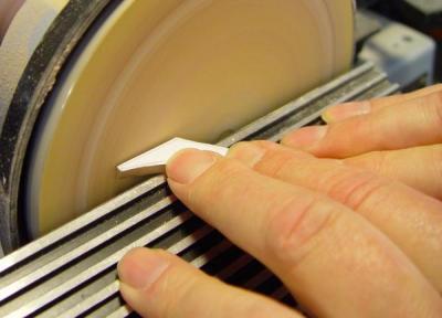
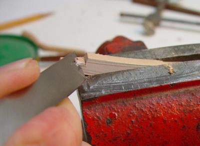
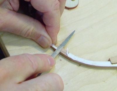
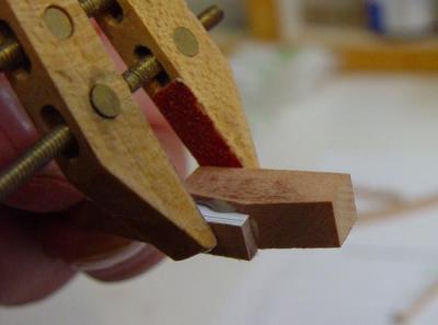
The following pictures describe how the horseshoe and dovetail plates were made and installed.
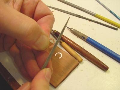
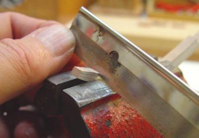
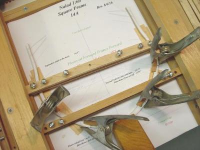
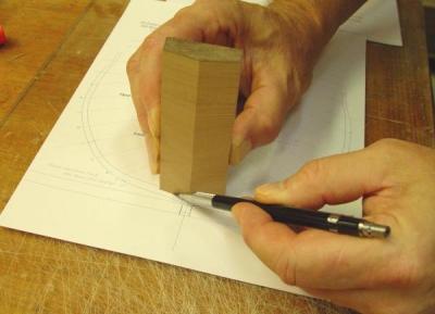
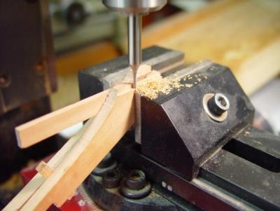
Surprisingly the roughly 3/8 inch diameter horseshoes turned out to be the easier. Both type plates are quite small and it seemed harder to get the dovetails symmetrical than it was to make concentric circles. In the above picture the outside diameter of the second plate is being filed to shape. The bolt holes were drilled first, before any cutting. A hole large enough for a round file was then drilled in the center and the center diameter filed out. Finally the OD was cut and filed off. The first plate is actually embedded into the scrap wood above – for practice before cutting into the real keel.
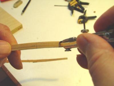
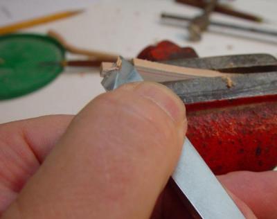
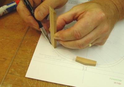
The plates were made from .020” copper sheet, much thicker than needed, to allow it to be more easily shaped. It was then filed down to about half this thickness as shown in the above picture. A tab at the bottom was left to secure this until being cut off in the final step.

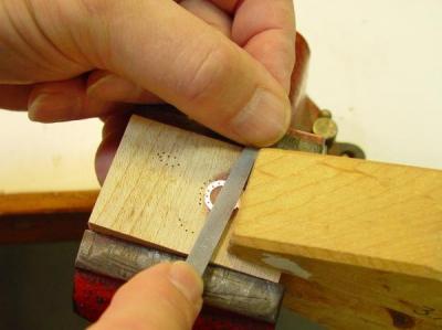
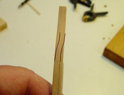
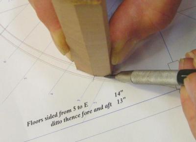
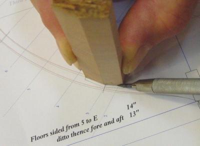
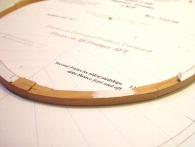
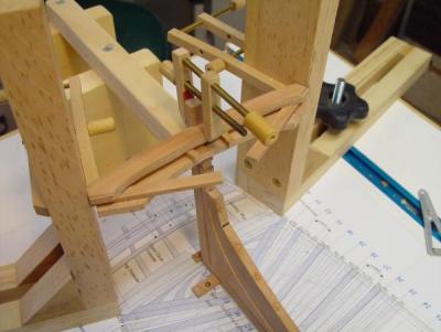
In the next picture the starboard horseshoe has been pinned to the keel and its outline being scribed on with a very sharp 6H pencil.
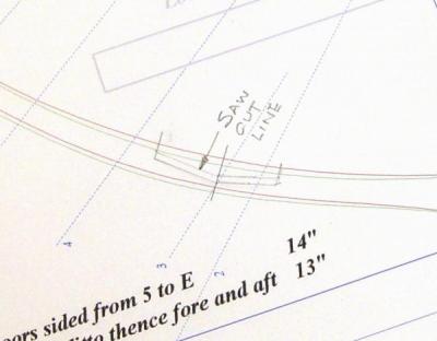
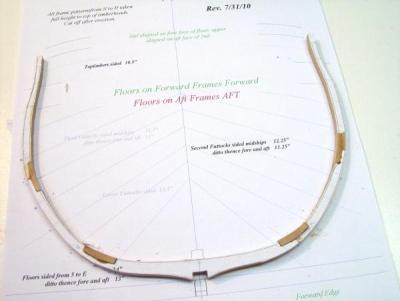
The marked out shape is shown below.

In these pictures the model is resting on foam carpet underlay. This cushions the hull and also keeps it from sliding around, while at the same time allows it to be repositioned easily as needed.
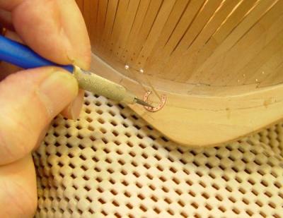
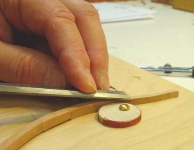
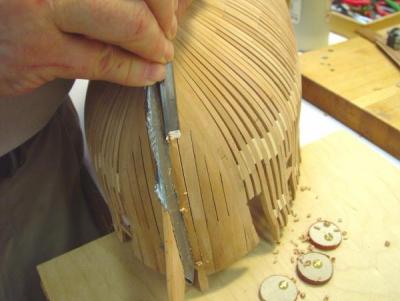
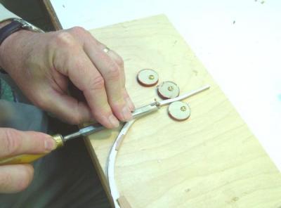
The following two pictures show the process of chiseling out the recess for the plate.
The first vertical chisel cuts were made inside the lines.
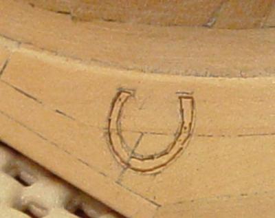
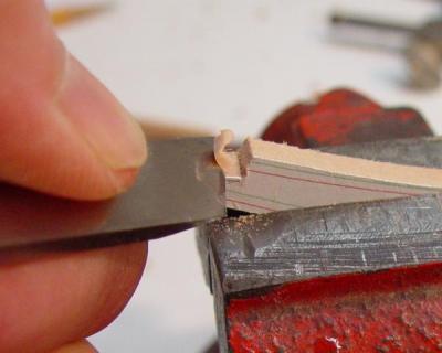
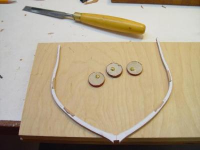
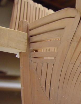
The inner part was then cut back with a 1/32” chisel and the edges finished to the line. The picture below shows the embedded plate.
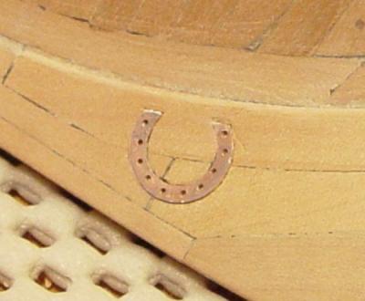
The final steps were be to CA glue it in, level it off with a file, drill shallow holes into the wood, insert and glue short bolt ends and then file those down. The dovetail plates at the keel were made and installed in exactly the same way.
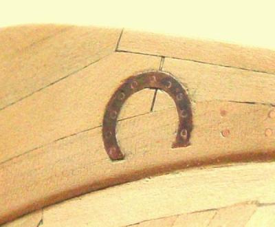
After filing the bolt heads down the plates were polished with fine steel wool, brushed with acetone to remove any residual CA or oil from the steel wool or my hands. They were then brushed with a solution of potassium sulfide (liver of sulfur) to darken them to a more “bronzy” hue. Liver of sulfur is very effective for darkening copper and colors from dark copper to steely black can be obtained by varying the concentration of solution or time of exposure. It could also be used after embedding the copper in the wood because it does not effect or discolor the wood, unlike selenious blackening solutions. When the right darker hue was reached the whole area was brushed liberally with clean water to stop the reaction and flush away the solution.
The following picture shows the result. These ultra close up pictures are scary because they show imperfections that my eyes at least, can’t normally see, but here it is.
After doing all this work upside down on the bench, it was clear that more strength was needed along the tops of the frames, so in the next part I will discuss the installation of temporary ribbands to fix that problem.
Ed
- Jeronimo, billocrates, aviaamator and 2 others
-
 5
5
-
1:60 HMS Naiad 1797
Part 21 –Lower Hull Finishing
Posted 11/12/10
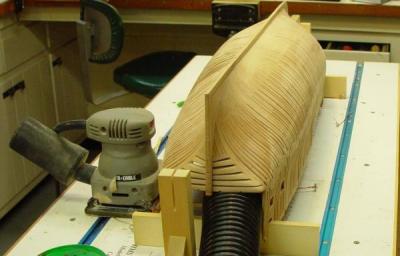
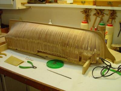
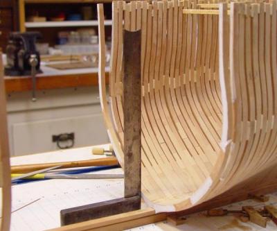
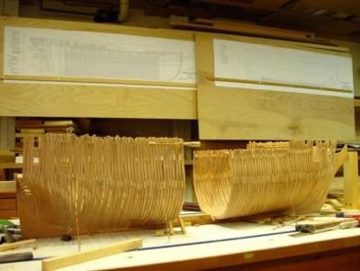
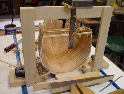
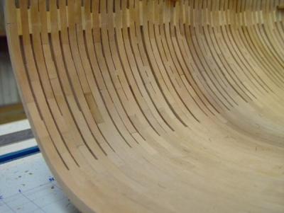
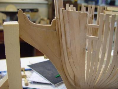
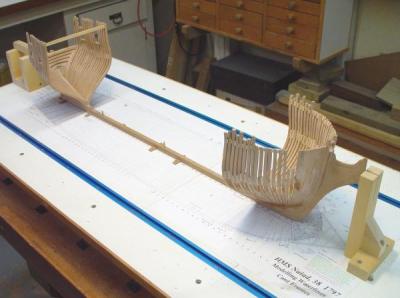
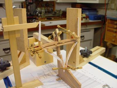
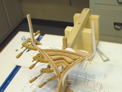
With the installation of the last of the frames, the next step was to fair the bottom of the hull. To provide a stable support for the hull in an upside down position a temporary fixture was made and fitted as shown below.

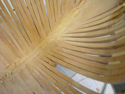
The hull was then faired, first with a cabinet rasp where needed, but mostly with the pad sander shown below, with progressively, 80, 120 and finally 220 paper. The flexible hose inserted under the hull in the following picture was connected to the new dust collection system and picked up virtually all the dust made in the sanding operation – a major change from previous sanding experience.
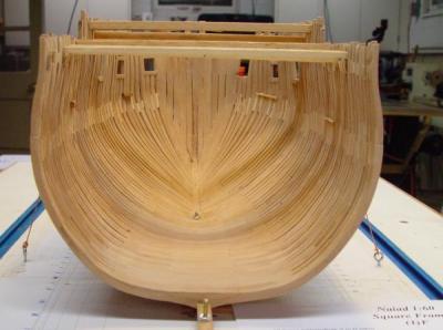
 The following picture shows the final faired lower hull. This process took about one hour per side.
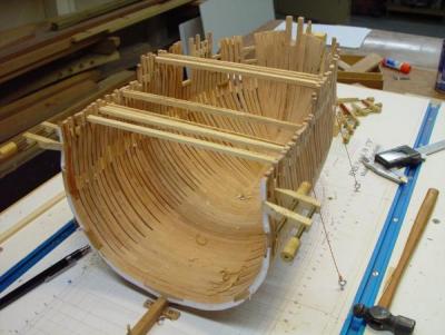
Below is another view of the faired hull.

The plan at this stage was to completely finish the lower hull, which would include installing all the copper joint bolts, installing permanent spacers in the main frame bends, making and fitting the horseshoe and dovetail plates, installing ribbands and final sanding and polishing. I had not decided yet when to install the rudder fastenings – pending a decision on how to plank under these – or not.
For these steps, the hull was moved to the workbench, as pictured below.
Main Frame Bend Spacers
According to Goodwin, Sailing Man of War, after about 1750, once the stronger chocked joints were used, additional steps could be taken to separate the upper timbers of the main frame bends to help reduce rot and structural topside weight. This was accomplished by bolting the halves through spacers above the lower futtocks, instead of directly bolting timbers all the way up. These spacers were bored vertically on either side of the bolt to permit airflow. This frame separation is shown clearly on the disposition of frames draft, but without Goodwin’s explanation I was initially confused by the drawing.
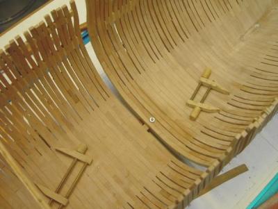
The following picture shows some of these spacers installed on the model.
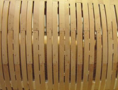
In this upside down picture the spacers have been glued between timbers of the mainframe bends only. The lower (upper in the picture) parts of these frames are glued together directly. Two spacers have been set between joints. A ribband will eventually go between these at the halfway point between joints. The spacers are not bolted on the model, but if I were to do this again, I believe I would install the bolts and the spacers before erecting the complete bend in one assembly. At this stage spacers are only installed on the lower hull. They will be added later in the topside areas that are not framed.
The above picture also shows the copper bolts through the chocks.
Copper Bolts
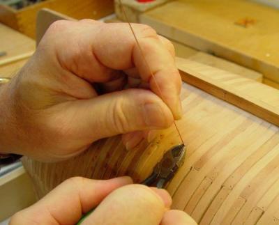
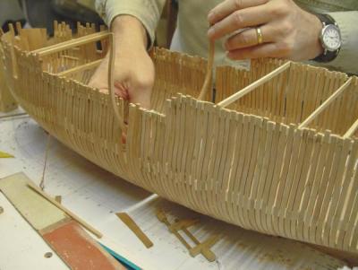
Copper bolts were installed on all the futtock joints of the lower hull at this time. They were made by stretching 22 gauge copper wire to the breaking point, dipping the end of a length of this in medium viscosity CA, inserting it through a predrilled hole, moving it back and forth to distribute the glue, then snipping it off. This is shown below.
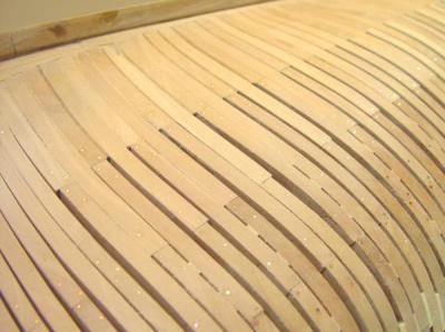
The next picture shows some of these bolts before filing and sanding.

After the CA was cured, the copper tips were filed down and the hull bottom completely sanded with 220 grit paper, with the grain. The result of some of this is shown below.
One other chore that had to be done at the stage was the cleaing up of the fore and aft frames surfaces. As can be seen in the photo some still had paper remnants or other roughness. This between–the-frames finishing was done with a thin file.
The next step was to make the horseshoe and dovetail plates.
Stay tuned,
Ed
- daHeld, Jeronimo, billocrates and 1 other
-
4
-
1:60 HMS Naiad 1797
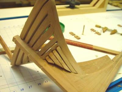
Part 20 –Curved Upper Timbers
Posted 11/10/10
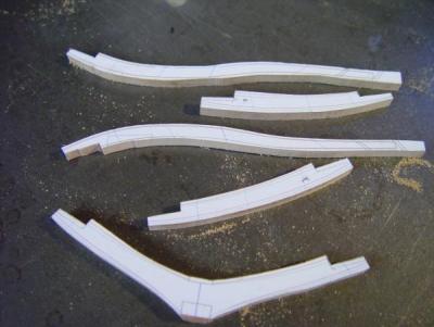
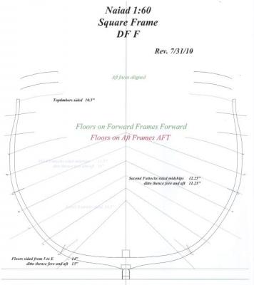
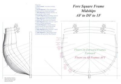
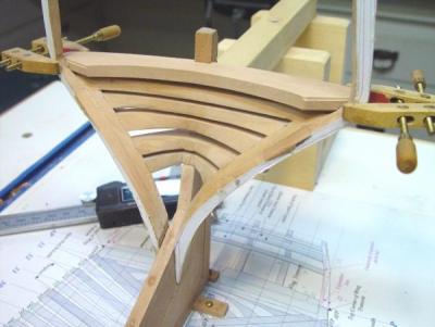
In the image below, taken from the CAD Frames drawing, a few of the timbers are curved in the fore and aft direction to provide support at the proper spacing for gun and sweep ports. As I mentioned earlier, all these timber spacings and offsets were taken from the original disposition of frames draft and I wanted to duplicate that as closely as possible.
The following series of pictures illustrate the steps I used to make the curved upper timbers.
The first step was to determine the width of timber (the siding) needed to cut out the curve. To determine this, a measurement was taken from the drawing of the total width of the final curved piece – the distance between its extreme verticals. A toptimber of this width, instead of the normal siding, was then cut out and assembled into the frame. The lower edge of this timber that would not require any cutting was set to the correct offset from the edge of the timber below.
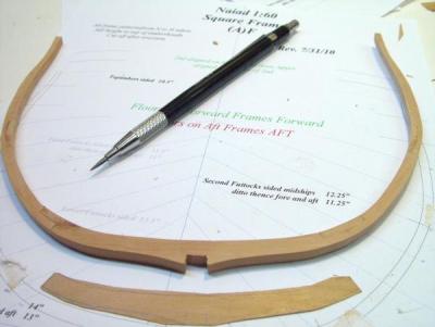
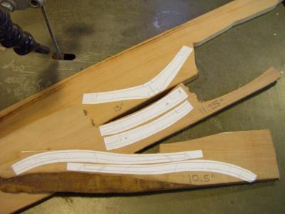
After assembly, the upper timbers were marked as shown below.
Here, using a compass with the point leg extended as a guide and set to the normal 10.5 inch toptimber siding, two lines were drawn on the piece – one marking the lower part to be removed and the other marking the top part to be removed. The result is shown below.

The height of the top and bottom of the ports was marked on the frame and also two lines spanning the distance of the curved part. Lines were then sketched of the curve roughly as shown. I roughly accented these on the image because the pencil lines are not completely clear.
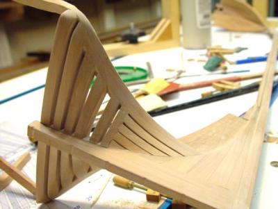
The next picture shows the top part being pared back in a smooth curve.
Note in this picture that the bottom side of the toptimer lies outside the edge of the timber below – for now. With one side of the curve formed, the other was traced in with the same compass setup.

The next picture shows the final line to be cut.
This part was then pared back to the new line. The picture below shows the result. Except for a few missing frames, this is exactly the area shown in the first image.
The next part of the narrative will cover the fairing and some finishing work on the lower hull.
Ed
- Jeronimo, billocrates and daHeld
-
3
-
1:60 HMS Naiad 1797
Part 19 – Aft Square Framing
Posted 11/8/1
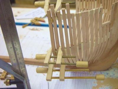
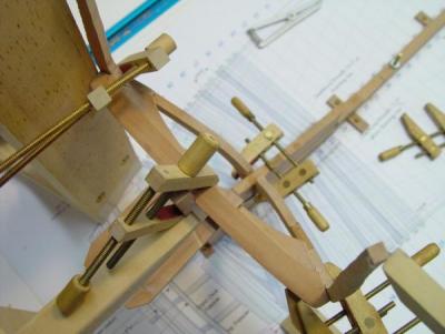
With the forward square frames installed back past the dead flat, all that remained was the 40 plus frames of the after body. The picture below shows one of the first of these being installed.
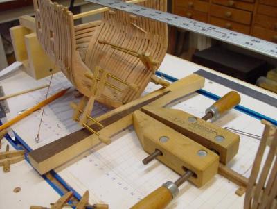
This picture illustrates a little better the various clamps and wedges used to assure tight glue joints at the base of the frame. The large (3/0?) Jorgensen Clamp is fastened to the keel to act as a stop for the long wedges.

Nothing special here – just me fitting up a frame to the rising wood. One improvement I believe I would make next time would be to glue and bolt together the two sections of the main frame bends before installation. Apart from following historical practice more closely, this would also assure a tight joint at the floor. Also, by bolting through the permanent spacers above the floors, the step of wedging them in later would be eliminated. At the upper timbers these could be bolted with treenails to avoid later drilling into metal for planking nails. On this model every frame half was installed separately.
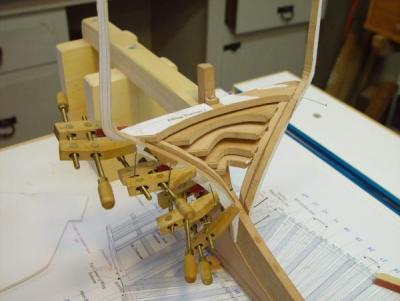
In the following picture a square is being used to place the timber right on its proper line. This placement set the thickness of the floor fillings.
In the next picture the sandwich of frames and fillings is being clamped together with glue. The wetness is the result of brushing excess glue off with water. This saves scraping later.

Another possible improvement for next time would be to surface off the filling on the milling machine after it is glued to the floor, instead of sanding it down as was done on this model. That would assure very parallel faces at the floor level and make the joints easier to keep uniform.
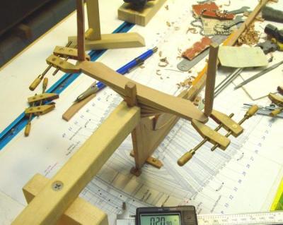
In the picture below a wood gauge cut to the thickness of the height of the cutting down above the rising wood (the space between the rising wood and the keelson), is being used to make sure the bed for the keelson is at the right height.
The next picture, taken toward mid-October shows the end in site.
Finally, only one left.
In the last picture, the final frame is being slipped into place. It was in and out many times as the filling was carefully sanded until it fit tightly. It was then glued in, the final few spacers were placed and glued, and the framing was finished – a major milestone.
In the next part, we will go back a few steps and discuss how the curved upper futtocks and toptimbers were made to accurately accommodate ports while matching the framing draft.
Ed
- Jeronimo, billocrates, daHeld and 1 other
-
4
-
1:60 HMS Naiad 1797
Part 18 – Forward Square Framing
Posted 11/7/10
When the forward cant frames were all installed, work on the forward body continued with the erection of the square frames. Throughout the framing work, frames were installed as they completed fabrication, so there were no piles of frames or parts, no labeling issues and less tedious repetition. In an average workday of 3 to 4 hours, the standard rate was 2 frames per day, from the printing of the patterns to installation on the keel. The beveled frames took a little longer, the unbeveled less time.
Below is a picture of one of the first forward square frames being installed. In this case, since it was the first square frame, I wanted to be sure everything was quite correct, so a cross member was installed at the top with the frame on its pattern to assure a match. A centerline was put on the cross piece and in this picture it is being used to square up the frame for gluing to the keel – actually to the rising wood. To assure a tight fit between the floor filling and the previous frame a wood block is wedged against a full size woodworking clamp that is tightened to the keel.

The next picture shows a variation on this process. Here two tapered wedges are being used for the same purpose. Small clamps are also being used to assure that the floor heads are tight to the filling pieces. I mentioned earlier that all the square frames have the floors or lower futtocks glued together – either directly in the case of main frame sections or with fillings for the joints with intermediate frames. This results in a continuous floor the whole length of the square framed hull.
Once the first few of these frames were installed, I used the cross pieces less and relied more on squaring up the frame with a square or triangle from the lines on the base drawing. This was simpler and faster and did not sacrifice accuracy.
Below spacers are being inserted and glued between frames. These spacers helped with the rough alignment of the upper timbers but their primary purpose was to space the timbers correctly forward and aft – at roughly the height of breadth and at the top. Later they would be removed as ribbands were added. This will be discussed later.
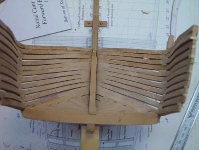
Below is a view into the forward body when most of the fore square frames had been installed. In both these pictures the solid floor is evident.
Below is another view of this. In both these pictures copper guy wires and small eyebolts can be seen. These were used to secure the hull to the board more firmly and also to maintain the position of the hull. Without body jigs it is necessary to make sure the hull is not leaning or twisting as new frames are added. These little guy wires are just 20 or 22 gauge copper wire looped through an eyebolt and around a toothpick inside the hull. When then are twisted up they put tension on the hull and restrain it from moving. When they become loose, they are just retightened. This is done with a square held to the height of breadth line to assure the correct position of the hull at each wire connection – both sides.

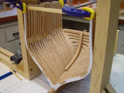
In the view below, the shape of the forward body is emerging. Frames were faired progressively, but at this stage still have a rough sanded (120 grit) appearance.

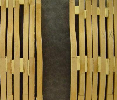
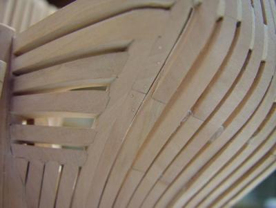
The next picture was taken with black paper inside the hull to show the spacing of the timbers and also some of the curved upper futtocks.
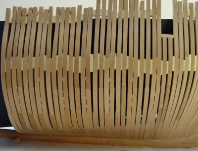
Close up photographic distortion aside, this picture illustrates some of the features I wanted to model realistically – the irregular spacings, the diminishing sidings of the upper timbers, the spacers between main frames, and the curved upper timbers to accommodate gun and sweep ports – which have not been cut yet except for a few. All this is as close a duplication of the original frames draft as I could manage. The permanent spacers are the small pear pieces toward the bottom. The lighter pine spacers will be removed.
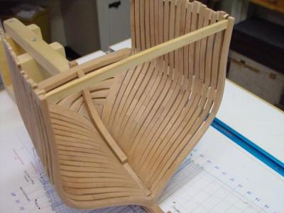
Finally, one more picture showing the inside of the forebody.
In this picture all the chocks are visible - another feature I took pains to model accurately. Much of this will be obscured in the final model. This picture also shows the inside fairing and the still rough and dusty looking 120 grit finish. I’m getting impatient to see the final polish on all this wood and the beautiful shades of the pear.
In the next part I will go through the progress on the aft square framing.
Ed
- Jeronimo, daHeld, billocrates and 1 other
-
4
-
1:60 HMS Naiad 1797
Part 17 – Some Backward Steps
Posted 11/6/10
The next phase, the installation of the square frames, took from mid July through to mid-October 2010, interrupted only by a week of vacation and a week of ugly rework, which I will describe before going to the more pleasant work on the frames.
Rework
This was by no means the first work to be redone. I keep a scrap box of rejected parts to remind me to be more careful and you will recall that two complete stern transom assemblies were made before getting one good one, but this was different because it involved a portion of the hull that I thought was complete – the bow timbers.
After erecting the first several square frames aft of the forward cants, I decided to do a waterline check on that part of the hull. Gauges were made for the 3, 6, 9, 12, and 15 foot waterlines for the forward third of the hull. These were set up horizontally at their respective heights and brought into contact with the stem and the first square frame, which was correct from top to bottom. I was amazed and pleased at how accurately these gauges matched the hull on both sides – except for the same two timbers on each side of the stem – the bollard timbers and the first hawse pieces. These revealed a hollowness of about 1/64 inch between the 6 and 15 foot waterlines. Small perhaps, but it was clear that any planking or ribbands crossing this area in the curve from the rabbet to the second hawse timber would be off the frames by that amount. The four timbers clearly had to be replaced. Anything else would be a patch job.
Apart from the potential risk of removing and replacing these, this also meant scrapping all the work at the top of the bollards, the bowsprit chock and the shaped timberheads – not a happy prospect.
To remove the two timbers on each side, I first cut down the middle of the first hawse piece with a jeweler’s saw down the air space on both sides. This was then only held in place by the end grain glue joint with the first fashion piece, so this was easily popped out. The bollards were removed by sawing down vertically just outside the glue joint then paring the joint off with a chisel. I felt there was just too much joint and too many other joints in the picture to try and soften all this glue with ethanol. I did use this on the beveled joint with the apron at the base of the bollards. I did not want to damage that part of the apron. This was all done without damage to the surrounding timbers. New replacement parts were then made.
I hope you will understand that I was not in a mood to take a lot of pictures of this, but I did take a couple when I began to see my way out of the woods.
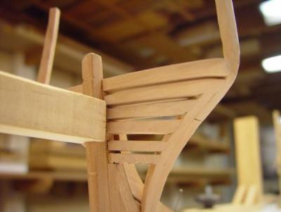
The above picture was taken after the new timbers were fit into place and glued. Not too bad. In the next picture the rough fairing to the correct profile has begun using a paring chisel. The layers of duct tape are there to protect the stem. This work was done very slowly with very light cuts.
The following picture shows the inside after rough fairing. The knightheads at the top have been neither sized nor squared yet.

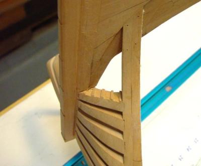
The next pictures show the outside at this stage.


The silver lining here was that I now felt confident enough about this kind of surgery that I began to look for other areas of improvement. The picture below shows a cant frame in the process of being replaced and there were a few more of these that were redone where they had been over thinned by fairing, or where fairing had exposed chock joints.
At the end of these unpleasant tasks, I felt a lot better about the quality of the model and a lot more sensitive to making sure work was right the first time before moving on. This is an important lesson and a good reason for dragging out all this dirty linen.
In the next part we will get back on track and discuss the installation of the square framing.
Ed
- billocrates, Jeronimo, fatih79 and 1 other
-
4
-
1:60 HMS Naiad 1797
Part 16 – Fore Cant Framing
Posted MSW 11/5/10
Like the aft cant framing, the installation of the forward cants took about a month. I found this part to be somewhat more difficult. Perhaps it was the pronounced curvature of the bluff bow of the ship, requiring more radical frame bevels. The odd discontinuous curves where the timbers project at the top may have contributed. The process described earlier was followed for these frames.
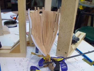
Here the pair of YF frames is being installed. These were the first to be topped with forecastle timberheads. The large clamped square to the right is being used in this case to set the frame at its correct spacing – serving the same purpose as the combination square seen in previous pictures.
Here the a starboard frame, perhaps VA, is being glued and clamped at its base, while on the other side a pair of spacers is being glued in between VF and XA. The profile gauge, which had been used to horn VF by its aft edge, as discussed earlier, is still lying around to the left. In using these gauges, the alignment for gluing at the base was done as accurately as possible. With the clamps in place this sometimes required the lower end of the gauge to be clipped out to clear the clamps – but always leaving the keel bearing edge intact. Later this alignment would be further refined and adjusted when the addition of the spacers again using the gauge.
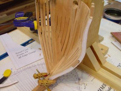
In this picture, the last of the cant frames, PA on the port side, is being glued and clamped. On the right its partner is getting its spacers glued in. The temporary spacer strip on the port side can be seen clamped in place temporarily while the foot joint is being glued.

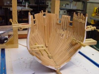
This picture shows the faired forward cants with their joint bolts installed. The floor of frame OF, the first forward square frame is being test fit on the rising wood. The floors of the square frames, at 13 inch siding, shows much thicker here than the 10 ½ inch cants.
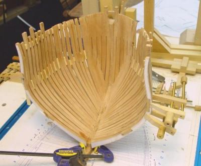
Here, that first square frame has been assembled, its joints finished and it is being test fitted with spacers just before being glued into place.
By mid July the cant framing was finished, and again, a celebratory cleanup of the shipyard was done for this picture.
In the next part our euphoric advance will take some backward steps. Stay tuned.
Ed
- Jeronimo and billocrates
-
2
-
1:60 HMS Naiad 1797
Part 15 – Aft Cant Framing
Posted MSW 11/3/10
In the last part the process used for erecting cant frames was discussed. This part will trace the progress of the aft cant frame installation from the middle of May to the middle of June 2010.
I believe I discussed earlier that all the framing is to be installed in accordance with the original spacing as far as that could be determined. The governing factor here is the spacing of the gun deck (upper deck) ports, which, except for one near midship, have equidistant spacing of 6’9” between them. The locations of these are of course on the original sheer plan and all are centered precisely on alternating intermediate frames lines – except for the one near midship. That odd single section frame (1) is always causing exceptions..
Based on the locations at the side, the timbers on either side of the ports could be fixed precisely. The cant frame plan on the half breadth plan and White’s drawings of Diana were used as a guide in spacing those in between. The spacing is thus somewhat irregular, more so at the bow. Different thicknesses of soft pine temporary spacers were used to set and hold this spacing as each frame was installed. Later as longitudinal members are installed they will be removed.
In this first picture the first starboard cant frame ahead of the forward fashion piece has been installed and attached to that piece with the temporary pine spacers. The port partner of that frame is glued and being clamped.

This picture shows starboard cant 31F being squared up from the board for placing of spacers. On the port side the paper pattern has been wetted for removal. The use of Elmers water soluble Glue Sticks was discussed earlier.
In the above picture installation has progressed to frame 28F – six pairs to go. In this picture the unfinished sternson knee has been pinned in place temporarily.
Some rough exterior fairing that has been done at this point. Until some wood has been removed there is always a question of the frames being set correctly. So far they were.
A pencil line has been sketched in at the top of the side to indicate the location of the bottom of the quarterdeck rail, where these frames will eventually be cut off. Some pattern paper remnants can be seen between some frames. These were later removed with water.
The above picture shows some of the first copper bolts installed.
This view from above illustrates the way the frames are spaced as the work approaches the beginning of the aft square frames.

In this picture the fairing has progressed well and copper bolts have been installed
Finally the first square frame is installed against the feet of cant frame pair 25F. The large clamped squares are being used to horn the frame in its proper place. A cross brace was also installed on this one to fix the topside spacing and make sure that the centerline on the brace was on the centerline of the keel. Protruding ends of some copper joint bolting can also be seen here. These will be clipped off and filed back. I will discuss bolting later.
Above is the final aft cant frame assembly - with a fair amount of sanding and some polishing done on the inside of the frames.

With the end of the aft cant frame installation, the shipyard was cleaned up in anticipation of the next phase – the forward cant frames.
The narrative is now running about 4 months behind construction but I’m catching up.
Ed
- billocrates, Jeronimo, fatih79 and 1 other
-
4
-
Thank you all for your comments. They will definately help keep me going as I put up the remaining 160 Naiad posts. Please be patient.
Danny, writng the posts in a word processor has advantages especially in disaster recovery - obviously. I used to write the posts in MS Word, inserting pictures into the .doc. Then I renamed the pictures with the number of the post and the number in the sequence, for example N16 02.jpg, then loaded the pics in the old member upload area and pasted the urls under the pictures in Word, then copied and pasted the whole doc into the reply editor, which ignored the actual jpgs in the doc and read only the url. Any editng was also done in the word doc, then saved. With the new site it is slightly different. Same process for writing and inserting pics, but after numbering the pics bulk load them using ctrl or shift using the attachment feature, adding the address code to the doc between the text. When previewed and finished I then copy the text out of the editor and paste it into a word doc, saving the final text, its formatting and the attachment addresses in the new system.
As far as pdfs are concerned, if you have Adobe Acrobat, you can save pdfs into MS Word documents. I just ried it on one of my posts - works great.
Cheers,
Ed
-
1:60 HMS Naiad 1797
Part 14 – Installing Cant Frames
Posted 11/2/10
This part will discuss the general process used to erect the cant frames. The next two parts will cover the progress of the installation of the aft and then the forward cant frames.
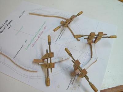
Beginning with the cant frames just ahead of the stern transom assembly, the first of these was installed in mid-May and the cant framing was completed at both ends of the ship by mid-July 2010. At both ends the work progressed toward the middle. Below is a picture of a cant frame clear of pattern paper, which in itself should illustrate some of the considerations in installing these.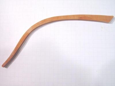
First they are in individual halves, which means they must be supported when fit up to keep them from falling over. Then, the only point of attachment to the backbone structure is the beveled foot at the bottom, which can be difficult to clamp in place. Although they are all the same thickness, or siding, the fact that the bevel angle diminishes as the center of the ship is approached means they take up decreasing space on the deadwood – but the full set must terminate at exactly the location of the first square frame. Finally, their upper spacing is not regular, but varies so that the aft end of a 2’11” wide gun port will be correctly spaced at the forward edge of every eighth frame with two closely spaced frames on either side of it. The spacing on the plan on the board helps with this last issue.
The process adopted for installing these frames developed as I scaled the learning curve. The pictures below will describe the key aspects of the process as it ultimately evolved. This first picture shows the use of a profile gauge to align the port side of frame SA.
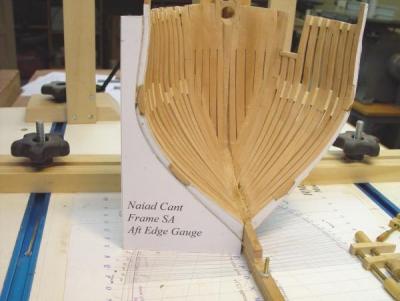
All of the forward frames were aligned by the aft edge and all of the aft frames by the forward edge. In this way I could use the profile line on the pattern on the exposed face for accurate alignment, even before fairing of the frame or even before trimming this face back to this reference line. To support this approach, patterns for profile gauges with the appropriate edge were put on the pattern sheets when the frames were lofted The frame patterns were marked starboard and port so the pattern would be on the exposed face when installed.
The patterns for the gauges have the bottom line coinciding with the bottom of the keel so they can rest on the board. The inside vertical edge coincides with the side of the deadwood at the bearding line. These patterns were mounted on illustration board with artist’s spray adhesive, the critical straightedges cut with a knife, and the curve cut out on the scroll saw.
The next picture shows how alignment in the fore and aft direction at the breadth was done using a combination square.
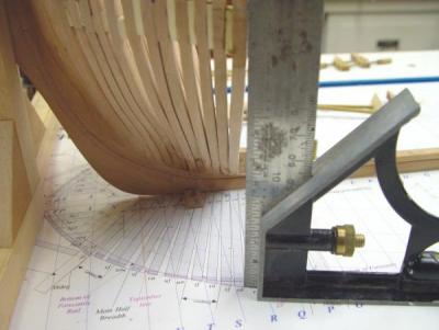
In the above picture, the square is set on the aft face of the frame on the drawing at the breadth on the frame. Based on this position, a spacer of soft pine was selected which would fit the space between this and the previous frame. One of the large clamped squares shown earlier could also be used for this step.
The picture below shows a port cant frame being glued at its base only, but with a spacer clamped at the breadth to keep the right spacing. The soft jaws of the Irwin clamp help with this awkward clamping problem. Several other clamping methods were also used. Whatever worked.
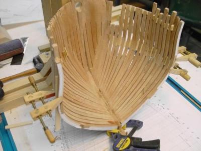
On the starboard side in the above picture a spacer is being glued in place to space the same frame’s starboard partner correctly against its forward mate. After fastening at the foot, installing the temporary spacers was the next step.
The picture below shows two of these being glued at the same time on a different frame.
These are temporary spacers, cut from soft white pine and will be removed later as longitudinal members are installed to maintain the spacing and strengthen the structure. Since these spacings vary, a variety of pine strips are kept on hand, so the right size can be selected easily while the alignment is being done.
Many of these spacers have already been removed and replaced to make adjustments in spacing and to put the gun port sides precisely in position and at the right width. Because they are soft, the spacers can be split with a single edge razor blade tapped with a hammer, then sliced out. Frame faces can then be cleaned up with a file. A new different spacer can then be fit. A thin Revlon metal finger nail file is very useful cleaning up faces that are closely spaced. Eventually, all the spacers will come out.
Below is a close up of the foot of the port SA frame.

This picture shows the pencil lines that have been put on the upper deadwood to aid in frame spacing. These were squared up from the drawing below. The goal is to end up with the aft face of frame PA exactly at the fore face of the first square frame OF. The faint green vertical line on the frame right next to the deadwood is the line of the forward face, which was beveled back earlier. The outboard lines can also be seen running down to intersect with the deadwood at the bearding line.
The next step in this process is shown below. In this picture a skew chisel is being used to pare the aft inboard side of the frame to the aft line on the pattern before removing the pattern. This is useful in setting the next frame, since the next frame’s aft edge should be close to this line.

Finally, the paper patterns were removed and the chocks leveled down to the frame face with a sanding board or file if needed. Then on to the next frame, which by this time should have been ready to come out of the assembly jig.
Further fairing was done on these frames as they progressed. First the lower inner edges of the frame were trimmed to the height of the top of deadwood, then paring, rasping, and/or filing, then sanding were done to provide a rough fair inboard surface. This was done in concert with outside rough fairing, keeping an eye on the sidings of the timbers at each level.
Final finish sanding and buffing will be done after all the bolts and permanent spacers in the mainframe bends are installed.
In the next part we will look at the progress made in erecting the aft cant frames.
Ed
- fatih79, flying_dutchman2, druxey and 3 others
-
6
-
1:60 HMS Naiad 1797
Part 13 – Cant Frames – Lofting and Fabrication
Posted MSW 10/31/10
Cant frames are half frames that bolt to the vertical surface of the deadwood above the bearding line at the fore and aft ends of the hull. They are angled forward at the fore end and aft at the after end. If square frames were used in these areas the bevels would be severe and the timber wastage would be huge. Each cant frame is at a different angle, which approaches 90 degrees to the keel toward the center of the hull as the first square frames are reached. The cant frames also get longer in this progression as the bearding lines, both fore and aft, drop down in height. Below is a picture of the aft cant frames taken later in the construction.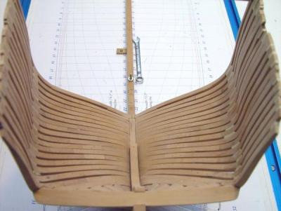
All these features mentioned above need to be accounted for in the frame lofting process, however, the most significant factor to be addressed in the lofting of these frames is the fact that on the body plans the views of these frame profiles are distorted, actually condensed horizontally, because they are viewed parallel to the line of the keel, at an angle to their true shape.
Below is a typical cant frame pattern sheet, in this case for UF, one of the forward cant frames.
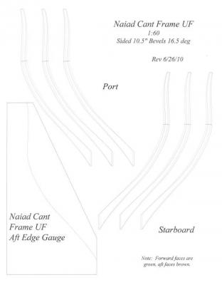
The cant frame patterns are different than the others described earlier. First, they contain three patterns each for the starboard and port frames. One is for cutting out segment patterns, another for assembly and a third in case of mistakes.
The pattern sheet also contains a pattern for a gauge that can be pasted to cardboard, cut out and used to set and check the frame position when being erected. The bottom edge of this will rest on the building board and the inside against the keel. These gauge patterns were added to cant frame patterns after the erection process was finalized because they are important tools for that process, which will be described later.
Like the square frame patterns, profiles are shown for fore and aft edges. Joint lines are shown as a single line only. All the cant frames are 10.5 inches thick, top to bottom, and this reminder is on every sheet.
The last important data on the sheet, different for every frame, is the bevel angle of the bottom face that mates up to the deadwood. Also the locations of the bottom squared off edges that will rest on the bearding line ledge are shown.
Like the square frames, separate worksheets were made to loft the forward and aft sets of these. The worksheet for UF is shown below.
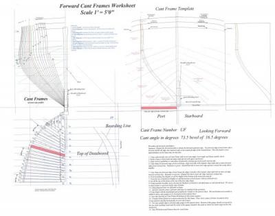
This worksheet contains much of the information included on the square frame worksheets – plan view of frames, body plan with frame profiles, a template area for developing the frame, and sheer plane views of the bearding line and the top of the deadwood. I will only summarize how this worksheet is used. The detailed procedure is given in a note on the worksheet.
On this example worksheet, the frame in question has been colored red, both in its position on the framing and in its rotated position on the development template - to help the explanation. Also, the two profiles needed for the lofting are colored and accented on the body plan.
The first step in this process is to copy the plan view of the frame, note its angle to the keel, rotate it to the horizontal, then place its inside aft edge in a vertical line with the deadwood. Vertical lines are then placed at the extreme edges, inside and out, for both faces.
To develop the true outboard profiles for UF, the UF profile, which was taken at its forward edge when drafting the body plan, will be used for the forward edge, and the next profile aft will be used for the after edge. They are copied, pasted and aligned as before. To develop their true shapes they are expanded by the CAD object handles out to the lines which were set up above at the edges of the rotated frame object – one at the forward and one aft ends of the rotated frame. The same is done at the inside.
Using the profile of the next frame aft for the aft edge is an approximation, but expanding it only to the actual aft edge of the frame makes it a more accurate representation of the actual aft profile. I won’t say any more about this to avoid being too confusing. But if there are questions…
Heights of the bearding line and the top of keel for both faces of the frame are then transferred to the template by means of the red diagonal line. Excess frame profile is erased below the bearding line for each face and the height of deadwood is used to terminate the lower end of the inboard edges. Inboard profiles are developed in the same way as for the square frames – using the red circles to set points. The frame components are then copied and transferred to the pattern sheet as before.
The standardized CAD worksheet greatly simplifies and speeds up the accurate lofting of these complicated frames. I hope this short version of the steps in this process is somewhat clear, but if not, the procedure note on the worksheet describes it thoroughly, for those with a keen interest.
The picture below shows some cant frame segments ready to be cut out from 10.5 inch thick pear stock. For some reason the patterns below do not include pencil lines for the chocks. For some of the earliest frames, I marked these out after placing the segments on the assembly pattern, but later found it to be more efficient and accurate to do this before cutting up the pattern.

The steps to fabricate these frames were identical to previous examples, but with a couple of additions. First, the bevel has to be cut on the mating face with the deadwood at the bottom of the frame. That was done on a disk sander using the tilt table set to the bevel angle given on the pattern sheet as shown below.
The last minor item is shaping the foot of the frame to match the bearding line curve. This was done as part of the erection process.
With the conclusion of this part, the discussion of the use of CAD for lofting frames is complete. I hope this has been helpful to those who CAD draft and loft their own plans or who might consider doing so in the future. The principles are conventional, but I found it challenging to look for ways to ease the repetitive processes – of which the frame lofting was foremost.
In the next several installments I will discuss the installation of all these frames.Ed
-
1:60 HMS Naiad 1797
Part 12 – Beveled Square Frames
Posted 10/29/10
Below is a pattern sheet and a pdf for frame 20A, one of the more highly beveled square frames - a few frames forward of the aft cant frames.
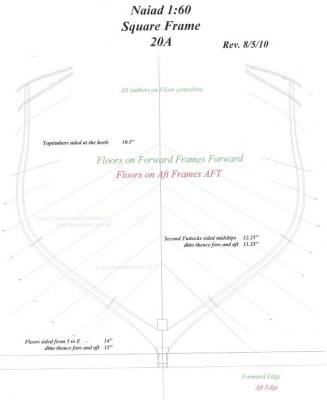
This pattern sheet contains all the information in the pattern for the deadflat frame example discussed in part 11, but there are some differences.
Because this frame is beveled to account for increased curvature of the hull in this section of the ship, two sets of profile lines are shown. The green lines describe the forward face and the brown lines describe the aft face. Also, the keelson is higher at this frame as is the top of the rising wood at this location. Finally, on this particular frame, all the timbers are centered fore and aft on the floor, unlike the previous example, in which all the aft faces were aligned. All these fore and aft alignments were taken from the disposition of frames drawing. These alignments varied to provide adequate air space and to place gun port sides at their proper spacing. This adds an assembly complication, which will be discussed below.
Following is an image of the worksheet used to develop this pattern.
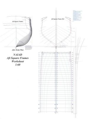
This worksheet was used like the worksheet in Part 11, with additional steps. This worksheet includes a plan of the aft frame locations and to the right of that a sheer plane view of the lines describing the top of the rising and the bottom of the keelson. These are needed to set these locations on frame patterns toward the ends of the hull.
Profiles from the left view are copied and pasted on the right view as before, but now there are two profiles because the fore and aft faces are different. Also, because the aft square frames are on the right side of the body plan they are placed on the right side of the pattern template.
Because this is the aft frame of the pair, the number 20 frame line profile is used for the forward face. The dashed line between profiles 20 and 21 is used for the aft face. The use of these additional dashed lines for frames that have significant beveling improves the accuracy of the pattern. The primary benefit of this, besides reducing the amount of fairing needed, is that it helps set the bevels of the chocks accurately, which reduces the chances of cutting into a chock joint when fairing, either inside or out. It also improves the accuracy of the aft inboard profile which is a saw cut line.
To set the heights of the rising wood and keelson bottom, points are set on the bottom right view, then transferred to the pattern view by way of the diagonal line, using the red transfer lines. These heights are different for the fore and aft faces, so four lines need to be set.
The inboard lines are then drawn as before, joint lines are set, all these lines are copied, pasted and flipped, and as before all the objects are transferred to the pattern sheet.
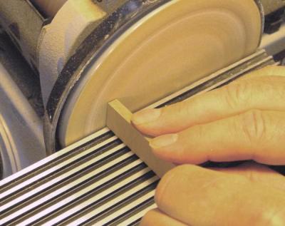
With the lofted pattern in hand, the next step is to mark out the chocks as before. However, because the frame is beveled this procedure needs to be modified. The picture below shows the first step in this process for beveled frames.

Because the frame is beveled, the chock joint surface must be beveled as well, which means that a chock joint line must be put on the pattern for both the fore and aft faces to define this surface. However, because the chock will be angled in the frame it must angled before tracing, because tilting the chock changes the apex angle on the face of the frame. The above picture shows how the chock blank is marked for beveling to get the right angle for tracing. If the chock blank thickness is close to the thickness of the frame, the amount to be removed from the apex side is about equal to the distance between the fore and aft profiles at that point. This approximation is adequate to yield a good joint and is being marked with a pencil in the above picture..
Below a chock blank is being beveled back to the mark made above before marking the frame.
Now the blank can be used to mark out both fore and aft joint lines and this is shown in the next two pictures. The beveled face should be held down flat on the pattern for this. The next picture shows tracing of the joint line for the forward face and the following picture for the aft face.
The next picture shows the beveled chock joint lines and notes the line to be cut out on the saw.
The paper patterns are now cut out and pasted to the appropriate size wood stock exactly as described in Part 11 and the segments are cut out and finished on their ends in the same way.
When cutting the chock joint line, however, the cut should be made on the innermost line as shown above, in this case the aft joint line. The next picture shows a set of these after cutting out.
Once cut out, each sawed chock joint face is dressed with a file to bring it even and square with the pencil line used for the cut. It is then beveled to the line on the other face as shown in the following series of pictures.
First, using a fine toothed saw, an angled cut is made down to the forward chock joint line, while not cutting into the back face.
Now, please do not be confused by the fact that while the last picture showed an aft frame with a smaller aft profile, the next three show a forward frame with a smaller forward profile. These example pictures are not all the same frame, but the process is the same. Sorry for this.
So, in this next picture, the first paring cut on the deeper (in this case the aft) chock line is being made. I use a skew chisel for this because I find it easier to control than a square chisel. The idea here is to pare down the corner of this edge to the pencil line.
In the next picture the corner is being removed in the opposite direction. Care is needed here to watch the grain direction and avoid chipping off the end of the piece. Small cuts and a very sharp chisel are in order here.
In the last paring step, shown below, the ridge left in the center is pared back leaving a flat surface for the chock. As a final step this is dressed smooth and flat with a file.
The chock is then fit as shown below and then glued and clamped.

When the glue has dried the bottom surface is sanded flat as before and the frame assembled on the pattern exactly as before, but before fitting up additional segments the joint surfaces of each needs to be pared and fitted to their mates as described above.
As noted on the pattern sheet, this frame has all its timbers aligned on the centerline of the floor. To do this, shims, which have been cut to the thickness of the offsets are placed under the upper futtocks to hold them at the correct fore and aft placement in the assembly jig. Otherwise the frame assembly and finishing off process is exactly like that described in Part 11. A variety of these shims ranging from 1 inch up to 3 inches are kept on hand for this.In the case of this frame, with its upper segments on the floor center, there will be offset joints to pare back on both sides of the frame in the finishing process.
In the next segment, the lofting and fabrication of the cant frames will be discussed.Cheers,
Ed
2013 Copyright Edward J Tosti
-
1:60 HMS Naiad 1797
Part 11 – Frame Assembly
Posted MSW 10/27/10
Frame Assembly Jig
With eighty-three square frame sections and seventy-eighty cant frames to be made, some sort of assembly jig was certainly appropriate. A picture of the basic jig developed for this is shown below.

The work surface is a piece of melamine-coated particleboard with the center area sized to fit a letter sized pattern sheet. Slotted wood assemblies on the sides hold down clamping strips, which will hold frame segments in position on the assembly pattern sheet. The side trays hold clamp parts. Below is a picture of this jig in use on the glue up of a cant frame.

Hardwood cross members are drilled and tapped to take tightening screws at a variety of locations. These tighten down onto hardwood strips below, which bear on the frame pieces. The ends of the cross pieces are held down by the side slots. Each clamp also has two screws, which fit loosely through the top members and screw into the bottom strips to hold the assembly together.
Having described the assembly jig, we will pick up where we left off in Part 10.
Frame Assembly
After chocks have been glued to the heads of their segments and their backs leveled off on the disk sander, as described in the last part, the lower pieces are clamped down on the assembly pattern. The adjoining segments are then fit up to it. Usually some file dressing is needed to get a precise fit. The clamps hold the timbers in place so any adjustments can be checked easily. When the joint fits well and the parts match the pattern, they are glued together. The hold-down clamps are applied first to assure the parts stay on pattern. Then clamps are put over the joints. This is shown in the picture below.
This picture also shows shims under the upper futtocks to provide the correct offsets in the fore and aft direction. This particular frame has all the forward faces aligned, so progressively thicker shims are needed under the upper segments so all the top (fore) faces are aligned.
Finishing Assembled Frames
The picture below shows a square frame ready for the last finishing steps.
A this stage the frame has been removed from the jig, the inside of the chocks have been cut back to the inboard profile on the scroll saw. The frame has been sanded down very close to the outboard and inboard profiles on a vertical drum sander, but no beveling is done at this stage. The notch to fit over the rising wood has been cut out and filed to fit. In this picture the frame is being matched up to the assembly pattern for a last check.
The next step is to pare down the excess chock widths on the front face and to finish off these joints in preparation for erection of the frame.The simple clamping device below was helpful in the paring process. It also helps avoids chiseling into fingers.
To make this, a 1inch dowel has slices cut off, just less than the frame thickness. Holes in these for screws are drilled off-center. Sandpaper is glued around their perimeters to help grab the work. They are then screwed loosely to a piece of plywood, which has a bench stop under its front side. The curved frame can then be pushed between the off-center discs and the cam action of the disks will hold it in various positions for paring.
The next few pictures illustrate finishing off of joints to the smaller siding of the upper piece, and if necessary, for any other jogging called for. This is done with a paring chisel and then dressed off with a small file.
.
.
.

.
.
As mentioned earlier, I leave the paper on until it absolutely has to be removed, to help in alignment and, on beveled frames, for rough faring of the inboard face after erection. In the above picture, paper has been filed off at the joints in the finishing process. When doing this, a file card is kept handy to remove paper residue from the file.
Floor Fillings
The picture below shows a final step for certain frames.
In this picture a filling piece of cherry has been cut which will be glued to this particular frame to match its floor. In practice these fillers were inserted between floors after erection to provide a continuous surface to help prevent bilge water from filling the spaces between frames. On the model these add authenticity and are very helpful in spacing floors correctly. Since floors of main-frame bends are bolted tightly together, these are used only in spaces adjacent to intermediate frame floors. There are three such spaces for each pair, one between intermediate frame sections and one each between these and their adjacent main-frame bends.
These fillers vary in thickness based on the disposition of frames drawing, averaging a little over 2 inches thick. They were glued to the frame before erection and then sanded off as necessary to match the required spacing. These fillers also add a lot of strength to the model in this area.
In the next part I will discuss how the preceding lofting and assembly process was modified to handle square frames with bevels.
Stay tuned…Ed
2013 Copyright Edward J Tosti
- billocrates, fatih79, druxey and 1 other
-
4
-
1:60 HMS Naiad 1797
Part 10 – Frame Lofting and Fabrication
Posted 10/25/10
With the completion of the stern timbers, work could begin on the hull framing, starting with the cant frames then working toward midship with the square frames. As I said earlier, this put the difficult work first and gradually progressed toward the easiest framing work – the unbevelled midship timbers.
However, I want to do the discussion of the lofting and fabrication of the frames in the reverse order, starting with the easy midship frames and ending with the more complicated cant frames. After that I will discuss the erection of the frames on the keel in the order I followed. I believe this will make the lofting discussion, in particular, a lot easier to follow.
Midship Timber lofting and Fabrication
On Naiad, the square frames, those that rest perpendicular to the keel, ran from frame Q in the forward body to frame 24 aft. Each frame line, except for one, had two frame sections.
For the main frames (2,4,6...B,D,F etc) two sections were bolted together to form frame bends. On these, floors were bolted directly to the lower futtocks, but above the floor heads bolts passed through spacers to maintain air space. On the original ships these spacers were bored vertically on either side of the bolts to allow air circulation to the lower regions.
Intermediate frames, odd numbered and lettered, stood alone with space between them. Altogether there were 83 square frame sections. Each is identified by its letter or number and by the letters A or F to designate whether it is the aft or forward section of the pair. Very few, if any of these are completely identical, although several at midship have identical profiles.
Here is the pattern for the forward frame of the Deadflat bend and a pdf version, which will be more readable. A letter sized pattern sheet like this was made for every frame section.
Each pattern has identity information and a revision date. Since this is the first use of these drawings, corrections are being made and the revision date keeps these straight.The pattern obviously includes the inboard and outboard profiles of the timber, but also some additional information to assist in constructing the frame:
All the diagonals, based on the original draft are shown. Each of these has a defined purpose, which is explained in a note on the worksheet below.
Joint lines are shown cutting through the profile at the appropriate diagonal for this section. In this case the floor heads and the heads of the second futtocks are marked at diagonals 3 and 7.
The siding (fore and aft width) of each component is given so it can be cut from the right size stock.
A large standard reminder of which frames have floors (vs. lower futtocks) is on every sheet.
Finally a notation, in this case “Aft faces aligned” tells how this frame is to be assembled. In this case it’s simple. All the aft faces are in a line.
Below is a simplified version of the worksheet used to loft this frame. Four worksheet templates were developed to loft frames of the following types: fore cant frames, aft cant frames, fore square frames, aft square frames. A copy was then made of each of these to develop a particular frame section then saved in case revisions or checking of that section were needed later.
This worksheet is used as follows to develop the pattern:
First the appropriate profile is selected from the partial body plan to the left. It is copied and pasted in the correct spot on the view at the right, which has all the basic construction lines on it.
The red circles on the left side of the right view are then used to set points which will be connected with a curve to define the inboard shape. The diameters of these circles are taken from the scantlings for each location up the frame. The red text indicates the molded breadth at each point, which is the basis for the red circles. Circles were adopted because in CAD they make placement of the inboard points very easy when placed tangential to the outboard profile at each point. The inboard point can then be placed on the inside circle tangent, eliminating angled measurements.
The lowest inboard point is set at the bottom corner of the keelson. The points are then connected with a curve and this defines the inboard profile.
The joint lines are added at the correct diagonal. A description of the diagonals is in blue text.
Once one side is formed, it is copied, pasted, flipped and positioned on the opposite side. Both sides, the keelson and the keel assembly are then copied and transferred to the pattern sheet as one object, where it is positioned on the basic frame reference lines – top of keel, centerline, diagonals and other key lines.
Midship Frame Fabrication
Two copies of each pattern were made. The first was used for marking chocks, then cutting and pasting patterns for each part on the wood stock. The second was used as a template for assembly.
All frame components are joined together with chocks like the original. I started out showing chocks on the patterns, cutting out the timbers, then making chocks to fit. This involved precisely cutting the seat for the chocks and then doing the same for the chocks themselves.
The simpler process I adopted is shown below. It obviated the need to draw all the chocks on the patterns and reduced the amount of fitting work. This approach saved even more time when it came time to do beveled chocks. So, based on this approach, the frame pattern drafting was changed to show only the joint line – no chocks.
In the improved process blanks from which chocks can be sliced off are shaped. One approach is shown below.

I soon adopted other approaches. These blanks can be made by tilting the table on the disk sander and beveling with the disk – making a lot of dust. Another way is to hand plane down the rough shape then clean it up on the disk. This is my current approach. Blanks with a few slightly different angles were made to fit different frame curvatures. Once these were beveled, the shaped face could be ripped off on a band saw for use.
The blanks are then used as shown below.
In this picture I am marking the chock joint line on the pattern. This is the first step in making a frame by this process. In this case it is the large chock between lower futtocks. The chock should be placed so its ends are about 1/3 into the frame.
The chock joint line for the head of the first futtock is being marked out in the picture below. The chocks blank selected should allow the apex of the chock to be positioned about one-third of the frame thickness from the outer edge and about the same from the inner. This is the reason for making a few slightly different shapes.
In the above picture the large center chock has been sliced off the blank. Before cutting this off, I marked the bottom side and then sliced it off on a circular saw. It is important to cut the chock from the end used for marking and make sure one side is identified, so it will fit its frame correctly. This procedure also avoids having to make chocks perfectly symmetrical.
Individual timber patterns are then cut out and pasted to the correct thickness wood stock as follows:
First, using a sharp X-Acto type knife and a straightedge, cuts are made along each of the pattern joint lines. This defines a precise mating joint between timber segments. The pattern segments are then cut out and pasted to the pear stock of the appropriate thickness. Some of these are shown ready for cutting out below.
Timbers were cut out leaving about 1/32” excess around the pattern lines, including the cut off end of the joint line. The joint lines were then sanded back precisely to the cut paper line as shown below. Once I settled on this approach for trimming the ends of the timbers, I could get by with one unexploded frame pattern for all the cutouts.

If this sanding step is done carefully, right up to where the paper was cut, the pieces of the frame will line up pretty well with the profile when butted together. The next step is to cut the chock joint lines. This is shown in the next picture.

The cuts are made just inside the pencil lines, then dressed with a file. Chocks are then fit and glued to the heads of each frame segment, making sure the chock is oriented correctly to the way it was traced. If care is taken to this point the chock should fit pretty well.

It is then glued to the futtock and clamped.
 ]
]Chocks are fitted and glued to all the futtock heads and set aside to dry as shown below. This is usually the time to start marking chocks on the next pattern.
When the glue has dried, the bottom side is sanded off flush on the disk sander as shown below.

At this stage the frame is ready for assembly. I will cover that in the next part.
Ed
2013 Copyright Edward J Tosti
- billocrates, fatih79, fangknight and 2 others
-
5
-
Thank you, Colin. Stay tuned. I will do what I can to get the log up soon.
Ed
-
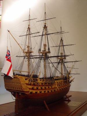
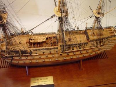
The log for this build was posted in mid-2010. I will be reposting it in between reposts of the Naiad log. The model was built between 1976 and 2009 - a long time, with many breaks in the work. To start this off, I attach a few pictures taken of the finished model for the 2011 NRG Contest.
-
1:60 HMS Naiad 1797
Part 9 – Stern Transoms Wrap Up
Once the transoms had been finally secured to their fashion pieces the assembly could be glued to both the sternpost and the deadwood, bringing to conclusion a challenging and interesting piece of work.
Here is a picture taken at this stage and after some tidying up of the work space.

This stage was reached at the beginning of May. The transoms were very roughly faired both inside and out. The sternson knee is also shown here pinned in place to help with the fairing.
The next step was to do some further fairing of the outside and install the four vertical filling pieces under the lowest transom. The following picture shows the lower transoms still largely unfaired, but the mortises have been cut in the lowest transom for the vertical filling pieces.
Here is a view of these mortises on the port side.
In the following picture some additional fairing has been done and the four starboard fillers have been rough cut without patterns, tenoned and fit into place on the starboard side.
These were installed on both sides and were faired as shown in the next picture.
The way was now clear to begin work on the aft cant frames. I will cover that in the next part and insert a section here on miniature woodworking clamps that have greatly facilitated much of my model making work.
Clamps
In the last section I mentioned the need for special clamps. A lot of my homemade clamps were in previous pictures. There are two types, one is just a miniature version of the Jorgensen style woodworking clamps that I have used a lot and find to be extremely flexible in a variety of situations. The other type is a simpler version and quite easy to make. The Jorgensen type are more involved. I will describe the easy ones first. Here is a picture of some of these.
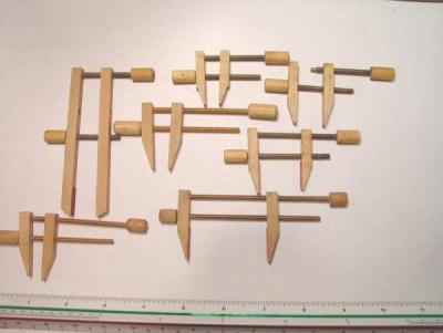
Most of the jaws are made of maple about ¼ inch square. The ends are tapered down so they will get into tight places, like between frames. Brass 6-32 threaded rod is used for the screws. The clamps are all oriented the same way in the picture for ease of explanation. In all these the top rod is threaded (in the wood) through the top end of the right jaw piece. The upper right hand clamp shows how the end of the upper rods are turned down to fit a hole in the top of the left piece so the rod can push against it. The bottom rod slides through a slightly oversized hole, unthreaded, in the middle of the left jaw piece and is threaded through the right jaw piece in the middle. Holes are of course all lined up. Sometimes gluing sandpaper between the jaws helps them grab at an angle. The knobs are turned, drilled, threaded and then screwed and epoxied onto the rods.
This has probably been confusing enough so I will not try to describe how to use these. They take some getting used to, but briefly tightening either knob will tighten the clamp if the left hand knob is in contact with the left jaw and the turned down end of the upper rod is in the hole in the right jaw. They can apply a lot of pressure. Some with long jaws or long rods, have a tendency to twist if not well aligned.
The second type is more complicated and more versatile. Some are shown below in an older picture with some miniature London pattern paring chisels.
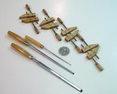
These are more complicated and making them requires some investment in both right and left hand 4-40 taps and dies. The jaws are also maple. The rods are threaded to the middle - at one end with a right hand thread and at the other end with a left hand thread so that turning one knob either tightens or loosens one end of the jaws. The rods are threaded through 1/8 inch diameter brass rod segments, which can rotate freely in the holes through the jaws. The holes in the jaws for the rods are really slots so the jaws can angle in different ways. Handles are threaded into the ends and epoxied. The brass ferrules are a little unnecessary extravagance. The handle end of the rod in the middle is right-handed. The handle end at the back end is threaded left-handed. Also, I later enlarged the slots that the threaded rods pass through to allow them to angle more freely. I have larger ones of these with jaw sizes rom three inch to twelve inch.
These do well in clamping non-parallel surfaces. They can also clamp parallel surfaces that are not aligned and of course they can clamp parallel aligned surfaces. These also benefit with sandpaper glued to the jaws. . These are very flexible clamps, which again, take some getting used to.
In the next part I will discuss lofting and fabrication of frames.
Ed Tosti
2013 Copyright Edward J Tosti
- bk01eeh, billocrates, daHeld and 3 others
-
6
-
1:60 HMS Naiad 1797
Part 8 – Stern Transoms
The stern transoms were the next step in my plan from difficult to easier. Because of some careless drafting of a couple of the supplementary waterlines at the aft end of the ship – the butt of the hull - the first completed transom assembly included some transoms that were too small and it had to be scrapped, adding to the growing pile in the scrap box. I would happily have hidden this fact, but I used a different process for the second assembly than the one I devised for the first and I believe both may be of interest, so I will describe both.
First, a picture of the finished version 2 assembly – the final version.
This picture was taken in June, so a lot more work had been done by that time, but it shows the features of the stern transom assembly pretty well. By the time of this picture many of the aft cant frames had been installed, but I will ignore that for the time being and stick to the transoms. There are six of these. The lower four filling transoms are tenoned into the after fashion piece (AFP). The third one from the bottom is a deck transom, so it is rounded up to match its deck. The topmost filling transom rests on the top of the AFP and both it and the wing transom are tenoned into the forward fashion piece (FFP). All the transoms are fit into mortises on the inner post, which were shown in earlier pictures. The four vertical filling pieces are tenoned into the bottom of the lowest transom with their feet resting on the upper end of the bearding line ledge. It is a fairly complicated structure.
Some may have noticed a slight anomaly in this picture. I will point it out later. It is easier to find than to explain. So if anyone can explain it, they will have my admiration. It was an interesting problem.
Lofting and Making the Transoms
To help define the shapes of upper and lower surfaces of the transoms, additional waterlines were drawn from the final body plan at 1 foot intervals in this stern area of the Full Breadth Plan – the one pasted to the board. The heights of these lines approximated the upper and lower edges of the transoms so were used to loft the transom shapes. Once the initial errors in these waterlines were corrected, this worked out fine, as long as some excess was provided when cutting the shapes. The tenoned faces for the transoms were of course, defined by the after edges of their respective fashion pieces.
With the patterns in hand the transoms were cut out, very roughly beveled and fitted snuggly into the mortises in the inner post. The next step was to cut the tenons and fit these into mortises on the fashion pieces – some complicated joinery at 1:60 scale.
Assembly Version 1
This next picture shows how I approached this the first time through.
The first step was to set up the upper two transoms, which would be tenoned into the forward fashion piece (FFP), in their correct final position. Spacers of the precise thickness of the space between them were then temporarily glued to them on either side of the stern post. Then spacers of the same thickness but of a longer length were glued between them exactly on the line of the aft face of the (FFP). Triangles were used to set these angled pieces from the drawing on the base. Note that the corners of the clamped squares are set on the corner of the FFP on the drawing and on the piece. This picture was actually taken a bit later after the wing transom tenons were cut. The next picture shows the tenon milling set up.

In this picture a dial indicator is being used to assure that the milling cut will follow the correct angle precisely, defined by the edge of the long spacer. The piece is adjusted in the vise until the indicator remains at zero as the vise is traversed. The long length of the spacer reduces error in these measurements. The next picture shows a tenon being milled. [
In this picture the tenon is deeper than needed and will be trimmed back to fit snuggly into the mortise after that is cut. In all cases the depth of the tenon was cut to the shoulder line defined by the long spacer and the width was set by the calibrations in the cross feed so that every tenon was precisely the same width.
To cut the mortises in the fashion pieces, they were first set up against the squared up transom assembly after the tenons had been cut. The frame was then marked with the tenon locations using a very sharp pencil. The mortises were then cut with a very small hand chisel. The next picture shows the assembly ready to be glued up.
It was important at this stage not to fasten the fashion piece permanently to the deadwood or the transoms to the post. This would prevent the addition of the lower transoms and their fashion pieces.
This is another view showing the glue up of the top two transoms.
The next picture shows the final assembly of the lower transoms and their fashion piece. This was made using a slightly different process that I ultimately adopted for the final assembly version.

When these two assemblies were fit up and fastened, there were two problems. One I mentioned above. The other was that there were some small gaps where the transoms joined the inner post, which could not be easily corrected. Either one of these problems would be sufficient reason to scrap this work and that is what I did.
Assembly Version 2
The main difference in this final, and I believe better, process is that it is much more incremental, allowing final fit up at each step of the assembly. Here is how it was done.
The picture below shows how each transom was marked for machining of its tenons.

In this set up, the transom, in this case the wing transom, was set in final position on the post and squared up. Two very flat pieces of plywood were set up with the clamped squares so that the aft side of the plywood coincided with the forward face of the fashion piece, in this case the FFP, to which that transom is joined. When this was done, a small strip of wood, equal in thickness to the fashion piece was held against the plywood and a line was made on the transom along this strip. This line is where the transom will join the fashion piece – the shoulder of the tenon. After marking, the transom was removed and a second line was drawn on each end to show the end of the tenon. The piece was then trimmed back to this second line on the disk sander.
The next picture shows a lower filling transom set up for machining.

In this picture the dial indicator is used as before but this time with less length to traverse. There are other ways to do this. A strip of wood could be set on the vice and the tenon face aligned with it. All these approaches seem to yield sufficient precision.
Once each transom was tenoned, it was set up on the post and a line was drawn on the fashion piece to mark the top of the transom. When removed, mortise lines were added. The mortises were then cut by hand as before. The fashion piece was then fit up to the transom and everything checked for alignment and tightness of all three joints – one transom at a time, starting at the bottom. This approach assured a good fit at each transom fit up.
The following pictures show these transoms being glued up, one at a time from the bottom – to the fashion pieces only – not to the post. Again the fashion pieces are only pinned temporarily to the deadwood until the whole assembly is finished.

In this picture the second lowest transom was being glued. First, the previous assembly had been moved forward, the new transom set on the post and then the assembly brought back into position and the fashion piece glued and clamped. These things were difficult to clamp. There are two variations of clamps that I had made years ago and those, plus some new ones, came in handy for this. I will describe these clamps in the next chapter.
The next picture shows the (conservatively sized) upper deck transom being glued.

Because of the round up, the fitting of the deck transom required some special handling. First, it was, of course, made from thicker stock measuring precisely the thickness of the timber plus the round up. Before fitting to the post the center part only was cut back on the bottom by the amount of the round up so the notch into the post could be fit. The ends needed to be left unshaped so they would be square in the milling vice. The tenons were then cut from the bottom edge, leaving excess to be removed from the top, which was then done. Both bottom and top were then rounded to the correct profile. The wing transom, which is also rounded up, was handled in the same manner.
One point worth mentioning regarding deck round up is that it is specified at mid ship. At the ends the deck is less wide, so round up of the transom needs to be reduced accordingly.
The next picture shows the top filling transom being glued to the tops of both AFPs, and also to the starboard FFP, which is also being glued to the starboard AFP. The port FFP was glued later.
Below is another view of this step. Note the tenon on top of the inner post. It was about to be removed. Why?
Finally the attachment of the wing transom. Like its predecessors, it was set on the post and the assembly, still not glued to the deadwood, brought up to meet it so it could be glued to the FFP. This is why the tenon at the top of the post had to go. Otherwise the assembly could not be removed. An alternative would have been to glue the fashion pieces to the deadwood and all the transoms to the post at this step, but I wanted to take this slow and make sure everything fit. The post tenon is hidden, anyway – but now you all know its not there.
These last two pictures show how conservative I was in sizing this last rendition of the wing transom.
I will wrap up these stern transoms in the next part and discuss clamps.
Has anyone found the anomaly in the first picture? It has something to do with the last two pictures.
Ed Tosti
2013 Copyright Edward J Tosti
- billocrates, fatih79, daHeld and 1 other
-
4
-
1:60 HMS Naiad 1797
Part 7 – Hawse Timbers
Posted MSW 10/20/10
Once the basic centerline backbone of the ship was in place, I elected to tackle the forward timbers that fill the space between the stem and the first cant frames. I then planned to do the stern transoms, then the stern cant frames, then the fore cant frames, then the fore square frames and finally the aft square frames in that order working toward midship. I did not appreciate at the time that this plan started with the most difficult work then proceeded with steadily decreasing difficulty to the easiest work last. So, right into the deep end. . . .
The forward timbers sent me directly back to the computer to draft profiles and to loft the patterns from which they could be cut. Since the hawse timbers are butted together with the vertical joints essentially parallel to the keel, profiles for the outside edge of these joints could be constructed by transferring points from longitudinal body curves (waterlines, heights of breadth, etc.) on the plan view, down to their corresponding lines on the vertical, or sheer plane, view, then joining these points with curves. There are five of these joint lines on the outboard faces of these timbers. The first describes the outboard inside edge of the first timber, the second the outboard outside edge. The second also describes the inside edge of the second, the third its outside edge, and so on. Below is a picture of the patterns for these timbers showing how the numbered profiles form outside and inside edges of each outboard face.
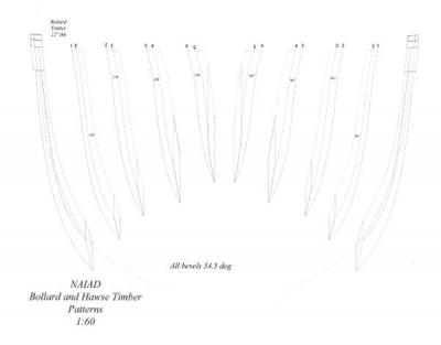
The inboard edges presented a more difficult problem, and frankly, a more complex drafting solution, which I decided to skip. Instead, I conservatively estimated the shape of the inside edge, and decided to finalize these inside shapes during construction. The dotted lines in the above drawing represent these estimated lines.
The hawse timber profiles were cut out on the scroll saw and their forward outside edges roughly beveled. Inboard faces were even more roughly beveled leaving most of the work until after assembly. The 34.5 degree bevels at the foot of the timbers were done on the disk sander with the table set to that angle. This left a very accurate, flat, glass-smooth surface. I normally use 220 grit on the disk.
Before the first hawse pieces could be installed, it was necessary to make and erect the forward fashion pieces and the first cant frame, which the hawse timber feet butt against. The port assembly of these three timbers is shown below.

This part of the Admiralty framing draft was not well drawn and it is somewhat unclear how these pieces were to be arranged. With some help from the White book on Diana and some interpretation, I concluded that the bollards and first two hawse timers butt against the first fashion piece, the third against the second, and the fourth against the first cant frame. The fifth is really just a small triangular filling piece. This arrangement can be seen in some of the later pictures.
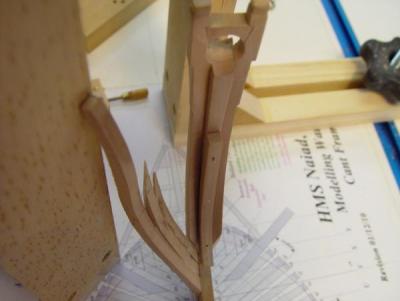
I will go into some detail on the drafting and making of cant frames later in the story, but these were the first to be made. Note in the above picture that the large clamped square at the left has its corner set at the corner of the first cant frame on the drawing and the top of that frame set at the same point on the corner of the square. This is one way that cant frames were positioned.
The vertical beveled faces of the two fashion pieces needed to be carefully surfaced and set up parallel to the keel so that they would match up to their correct hawse timber faces.
Unfortunately, I did not take pictures of each step of this construction, but below are some pictures taken after all were installed and rough faired, inside and out.
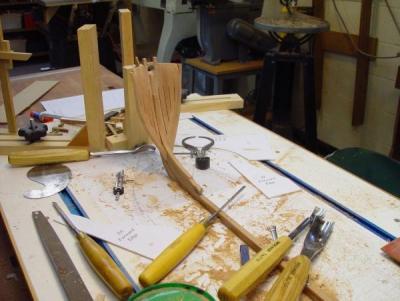
In the above picture and the next few, all the hawse timbers, the fashion pieces and the first cant frames have been installed and rough faired inside and out using some of the tools lying about in these pictures and also a rotary tool. The outside profile was faired first. Then based on the scantlings at each height, measured with the calipers lying on the board just off the starboard bow, the inside surface was shaped back.

This picture shows how these timbers fit together against their respective fashion pieces and the first cant frame. Before attaching each one to its neighbor, the air gap of about 2” was created by paring back each adjoining face from the foot up to a point somewhat below where the hawse holes will eventually be bored. When gluing adjoining pieces together and at their feet, temporary 2” spacers were inserted to maintain this gap.
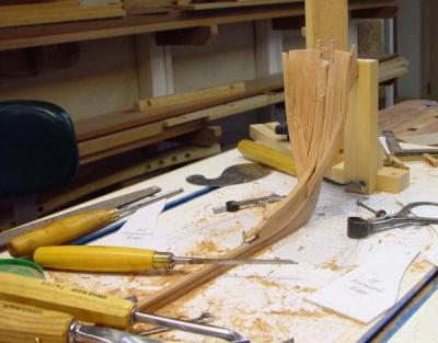
The picture below is a closer view, showing a few things worth mentioning. The forward extension of the keelson is shown pinned in place temporarily, mainly to help bring the forward fairing to a neat closure with it. Also shown is the sturdy pine support, which will keep the fore part of the hull vertical throughout construction. A few little faults are also apparent. The burn marks from the rotary tool on the starboard side will eventually be covered with internal planking, after which they will no longer irritate me. There are a few exposed holes drilled for locating pins that can be seen, reflecting the difficulty I had in visualizing the final limits of these timbers. All in all, I was pretty happy when I reached this point.

The last picture shows the whole assembly on the starboard side after the addition of the second cant frame, which was directly bolted to the first to reinforce this whole front structure. The joints between futtocks in both these frames can be seen clearly here. They are chocked on the inboard side and will be strengthened with copper bolts.

It would be untrue to say all this went smoothly, and my box of scrapped parts will confirm this, but now that I’ve done it once, I think I understand the structure and it will be a lot easier next time.
This stage was reached in the middle of March 2010.
Ed
2013 Copyright Edward J. Tosti
-
Thank you, all for these comments. It will take me some time to repost all the parts, so I hope you will be patient.
As to the question on the Victory log. Victory was my first model, built between the years of 1976 and 2009, years when there were other priorities in my life - like family and work. I posted the log as a retrospective build when I first joined the forum. Although I took copious pictures at the end, early photos are sparse and the blog has fewer parts than Naiad. However, I will be reposting it, but right now I'm focusing on getting the Naiad log back. I will try to get some of the early posts back up soon.
Ed
-

The Frigate Naiad was published by Seawatch Books in September 2012. I am starting this topic to capture reviews, questions or comments on the book. I will also use this space to post any updates or corrections to the content. I am sure there will be some, but hopefully they will be minor.
The content of the book is entirely different than the build log on this site. It is very oriented toward how-to-do-it subjects, whereas the build log is more of a day by day progress update.
Please feel free to add comments here. I will be glad to address questions as well.
Thanks,
Ed
-
1:60 HMS Naiad 1797
Part 6 – Stern and Stem Construction
Original post 10/18/10
Stern Deadwood
After the timbers of the aft deadwood had been fayed and glued together, the next step was to reduce the deadwood above the bearding line to the final width of 14 ½ inches. This width is equal to the full breadth of the deadwood, 18 ½ inches, minus the 4 inches required for the two 2 inch ledges to support the cant frames. These ledges follow a curve on each side of the hull called the bearding line. On Naiad, this was a continuous curve, not stepped.
The bearding line needs to be located accurately so that when the hull is faired the feet of the cant frames remain at roughly their 2 inch thickness (.033” at 1:60) and do not get faired down to less or, in the worst case, nothing. The bearding line can be copied from the original draft and put on the CAD version, but I think it is preferable to develop this line directly from the CAD body plan profiles, which are being used for all the other lofting.
The bearding line passes through all the points on the hull at which the moulded breadth of the hull is equal to the deadwood thickness - 18 ½ inches. Placing a vertical line on the body plan at half this breadth from the middle line, allows heights to be taken off at each frame line to plot the bearding line in the sheer plane. This was the approach used to plot the forward and aft bearding lines on the Naiad CAD drawings. The bearding line was a bit of a mystery to me until I visualized it in this way.
With a pattern for the aft bearding line in hand, the line was then marked out on the stern timber assembly, which was then set up in the milling machine as shown below.

The next picture shows a closer view of this setup.
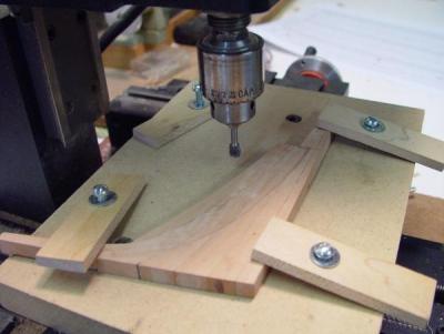
I will not walk through all the steps of this milling process, but only touch on a few points. First, the work, of course, must be horizontal when milling both faces, so the assembly, which when finished will be narrower at the bottom, was not tapered until after this process was complete. Second, the machining was only carried up to within, say 1/16 inch of the bearding line, leaving the final cutting to be done with hand chisels. Finally, with the top deadwood machined to its final width, the centerline of the assembly was then determined from this and marked on all edges of the piece.
After this machining, the sternpost and inner post assembly was attached and the whole fastened to the keel. In the following picture this assembly is shown shored up by one of the clamped squares discussed in Part 4.

Again, at this stage I was taking few pictures. Cutting out and shaping the sternpost assembly was fairly straightforward. Heights and sizes of the mortises for the transoms were taken from the large Centerline Structures drawing.
The stem, apron and forward deadwood assembly was made and attached to the keel in much the same way as its aft counterpart. Here is an image of the pattern sheet for the forward structure.
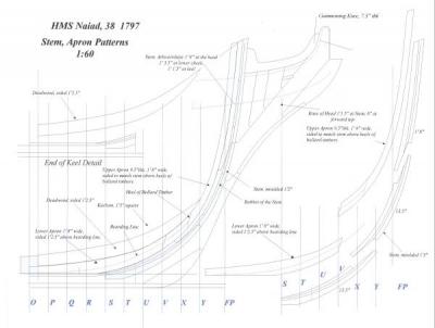
There are more complicated components here, but the process is essentially the same. A separate pattern sheet was made for the knee-of- the-head parts. When all these parts were assembled and attached to the keel, the entire assembly was set up as shown below.
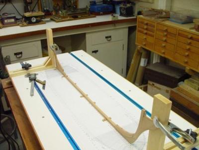
Permanent supports for the beakhead and sternpost were added later to replace the temporary clamped squares shown in this picture holding the ends vertical. The keel was maintained on center with the small wood blocks screwed into the base with another placed just behind the sternpost.
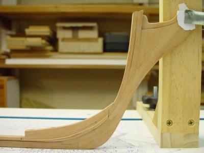
In the above closer side view, the bearding line still needs a little trimming and the stem rabbet has only been cut at the top, leaving the section down to the keel rabbet still to be done. The “rising wood,” that is, the deadwood in the center section of the hull is also visible in these pictures.
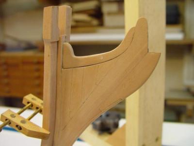
This picture shows the details of the beakhead assembly with the gammoning knee in place and also the initial fitting up of the bollard timbers. The picture below shows another view of this.

In the following picture the bollard timbers have been installed, the knightheads shaped and the bowsprit chock installed. Also the first forward cant frames on the port side are being positioned, but I will save the cant frame discussion for later.

The bollard timbers have a complex shape. The inside faces are curved to match the curvature of the sides of the stem, which expands in breadth as it rises from the keel. The fore surface matches up to the curved rabbet of the stem, then curves aft matching the hull profile. The aft (inside) surfaces are curved to maintain the correct molded breadth at each height. The aft foot is beveled 34.5 degrees vertically with its edge fitting into a relief cut at the same angle in the apron piece above the bearding line. The outside edge, which is thankfully flat, is cut back about 1 inch over most of its length to give an air space when the first hawse timber gets butted up against it. Finally, there is a complicated bit of fancy joinery needed to get the bowsprit retaining chock to fit neatly between the upper parts, called the knightheads, which get their own little bit of shaping. The next picture is a closer view of all this.

These bollard timbers turned out to be simple forerunners of what was to come with the modeling of their neighbors, the hawse timbers, which will be covered in the next part.
Hold Down Bolts
At this stage it was necessary to bolt the keel down securely to the building board, and it was a relief to turn to some work I could get my mind around. For the hold down bolts, special threaded studs were machined in brass as shown below.
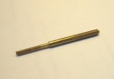
Three of these were made and were spaced out on the keel. Eventually they will be the permanent mounting bolts for the model. The idea behind this design is that the smaller diameter threaded part of this (4-40) will come up through the keel. The shoulder of the larger diameter will be stopped at the bottom of the false keel. Three small (4-40) nuts from above and three larger nuts from below will hold the keel down, initially. Eventually a small nut will be embedded just below the keelson. With the shoulder screwed up against the keel bottom, the top of the small section will be cut off flush with the top of the nut. This will prevent the keelson from being popped off by over-tightening this bolt from below later. The larger size nut under the building board or the base of the case will then hold the model down.
All this work was completed by the end of February 2010.
Ed Tosti
]2013 Copyright Edward J Tosti
- billocrates, Saburo, JerryTodd and 7 others
-
10
-
1:60 HMS Naiad 1797
Part 4 – Devices and Tools
Special Devices
The first items to be constructed were the building board and some measuring tools. The building board is shown below, clamped to a woodworking bench top.

The board itself is a piece of ¾ inch medium density fiberboard (MDF) with some pine stripping around the sides. MDF was chosen because it is very flat and smooth. Two slots were dadoed into the top to take lengths of T-track. The board was then mounted on the 2” X ¾” pine framing salvaged from the Victory building board and screwed down along the sides and near the middle. It was checked for flatness and shimmed underneath in a few spots to make it perfectly flat and well supported by the frame. Before assembly the top and bottom were given two coats of white shellac to seal its porous surface. The top was then sanded and given two coats of flat acrylic latex paint. The centerline for the keel was scribed into the top midway between the two T-slots and a print of the full breadth plan, described in the last part, was then pasted to the top using artist’s spray adhesive. The plan was then sprayed with Krylon Protective Spray. This spray allows glue drips and blobs to be peeled off and protects the drawing from moisture.
Mounting this drawing on the building board is a key enabler in the way the ship is to be built. Positions of frames and points along the frame profiles, like main half-breadth or the toptimber line, can be squared up from the board to assure correct placement. This was particularly important in setting cant frames and in marking out tenons on the transoms, which I will discuss later. I prefer this approach to the use of whole-hull jigs for the “horning” of frames, but that’s just a personal preference.
Revisions are inevitable when drawings are used for the first time, and I had to make some important changes to some of the profiles. The sections of the drawing can be removed from the board pretty easily with mineral spirits and replaced with revised sheets as needed.
So far, all this has worked out very well. One improvement I would make on the board based on its use so far, would be to use an oil based alkyd finish on the top – matte or semi-gloss white. This is a harder finish than the latex. Another approach would be to use melamine coated particleboard. I use this on my bench tops. It is very durable and anything can be scraped off with a razor blade. It would also eliminate the painting steps. Next time.
The “gantry” device in the top picture is shown close up below.

This device is similar to one I made and used on the Victory model, but with some improvements. The T- track allows easy clamping at any at any point along the ship. The edges of the two base parts align with one side of the top cross piece, so that placing the bases on a joint line, for example, aligns the top with that line. The T-track knobs allow the base to be clamped very firmly in position. Of course, in making this it was important to square it up well in all directions. The top crosspiece is scored with the centerline. A device for transferring vertical points to the inside of the hull will be added to slide on the top rail. This will be made later when needed. It will be similar to the device described below for transferring external hull heights from the drawings.
In addition to this, the two sturdy squares shown in the picture below were made. This picture was taken somewhat later in construction.
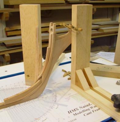
These squares also clamp into the T-track and are made strong enough for clamping parts or shoring up frame sides. They were carefully squared in both directions so that the face and the sides of the vertical members are accurate.
A device for transferring vertical external measurements from the drawings to the model was also made and is shown below.

This device, made from boxwood, is used to take vertical measurements from the bottom of keel line on the drawing and transfer them to the work. The horizontal base and the upper horizontal arm are tapered to a sharp edge. They are also held in position and made exactly parallel when the adjusting screw is tightened. This 4-40 knurled screw is threaded directly into the hard boxwood and puts pressure on a concealed brass plate when tightened. The confined brass plate prevents screw damage to the vertical wood post. Below is a picture of this device in use.
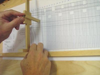
The various sheer plane (elevation) views of the ship are mounted on ¼” plywood, which are hung nearby. A straight strip of pine is screwed down on the drawing so its top is just on the datum line for measurements, in this case the bottom of the keel, which corresponds to the base of the building board. Dimensions can then be transferred quickly to the work.
Other devices and jigs made to support the construction will be discussed as part of the specific construction steps.
Tools
This is probably a good point to mention the tools for this work. As far as full sized machinery is concerned, some typical woodworking tools are being used. They include a 10” table saw with a thin kerf, carbide tipped blade, a 14” Rockwell band saw usually fitted with a ½” Woodslicer Blade, a tabletop drill press, a scroll saw, and a disk/belt sander. A reciprocating spindle sander would be nice, but the drill press fitted with a sanding drum lowered into a hole on the baseplate has been serving very well so far. The usual hand power tools, including a pad sander and a detail sander have been useful for fairing and finish sanding.
Model sized machinery includes a vintage Unimat SL (lathe/ mill/ drill press/ tablesaw/ etc.), a Sherline milling machine, a Preac miniature table saw, a 4” industrial model making table saw, and a (brand new) Hogg thickness sander. This last item is essential for producing the variety of timber thicknesses called for in the scantlings.
As this is being written, I am in the process of installing central dust collection. This will be a major improvement, especially for the sanders.
Hand tools of many sizes and varieties are of course needed, as are the right tools for keeping them sharp. A variety of measurement tools, like dividers, squares, triangles, digital calipers, etc. are essential.
A variety of special clamps have been made or acquired over the years to handle the unique demands of ship modeling. I will discuss these later when they appear in the actual work.
In the next part, we will enter into the actual construction work – at last.
Ed Tosti
2013 Copyright Edward J Tosti
- daHeld, Alex B., Captain Poison and 9 others
-
12
-
1:60 HMS Naiad 1797
Part 3 –Additional Drawings
In addition to the sheer plan, three other large drawings were made to support the early stages in construction of the Naiad model and to be used later for lofting. The main portions of these drawings are shown below. The full drawings also include end views, more notes and other detail.
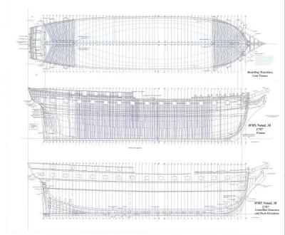
I will describe below each of the three views shown above.
Modeling Waterlines and Cant Frames
The top view is labeled “Modeling Waterlines and Cant Frames.” It is, among other things, a full breadth plan. It includes, all the frame lines (including intermediates), a plan view of all the cant frames, plans of the bow and stern framing, etc.
This view also includes what I have called “modeling waterlines.” These are not the original draft waterlines, which were not keel-parallel, because the ship rode deeper at the aft end. I put the actual waterlines on a separate view and used them only to check the CAD Body Plan. Then I added keel parallel waterlines based on the that Body Plan. The reason for this was that the actual waterlines are actually curved in the body plan, especially near midship where the profiles are closer together. This introduces complexity and potential error when trying to work with them to generate other profiles. Keel-parallel lines are much easier to use and this justified creating two complete sets of waterlines.
So, the waterlines on this drawing are parallel to the keel at 3-foot intervals above the top of keel, plus some additional ones above the heights of breadth and some at closer intervals around the stern transoms.
Other key longitudinal lines are also shown on this plan, including the height of breadth line, the sheer line (or toptimber line) and bottoms of the fore and aft top rails. All these lines were drawn from points on the CAD Body Plan. After fairness checking of all these longitudinal lines, they were used to add additional body plan lines, including: all the intermediate frame profiles, additional lines between these near the fore and aft ends of the ship where the frame bevels are pronounced, and all the fore and aft cant frame profiles. The way these additional lines were used to efficiently loft frames will be discussed later.
A print of this top drawing has been pasted to the top of the building board as a construction template and for this purpose a lot of other detail and text, readable from both sides, was added to it.
Frames
The middle drawing in the above image is the “Frames” drawing. It is a duplicate of the original disposition of frames draft with some details added. It shows the location of these frames on the keel and how the room and space requirements were met by the spacing of these and their components fore and aft, while maintaining the correct distance between gun ports. The sidings (thicknesses) of the frame components for this drawing were taken from the Shipbuilders Repository 1788 and these were consistent with measurements on the original draft.
Centerline Structures
The bottom view is titled “Centerline Structures and Deck Elevations. (Actually the deck elevations, including beams and details, will be done on separate plan and sheer plane views, not on this drawing, so it will be renamed.) This view details the sternpost/deadwood/keelson structure and the forward counterparts to these. Patterns for all these components were made from the objects that make up this drawing.
Frame Profile Development
The following image shows the way the many additional body plan profiles were drawn and how the use of CAD simplified this process.
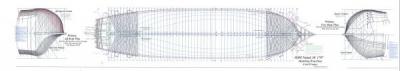
Normally body plans are drawn in the vertical position to facilitate transfer of points from the sheer draft to create longitudinal lines in the body plan view. Then waterline breadths, for instance, need to be picked off and transferred to the body plan to create more profiles. In CAD the body plans can be easily split and rotated. Also, once a waterline is drawn, it can be copied, pasted and flipped vertically to show an exact duplicate on the other side of the ship. In the above view the fore body plan is shown at the fore end of the ship and has been rotated to the horizontal. The aft body plan has been similarly rotated placed aft. In these positions points from the longitudinal lines can be directly placed on the body plan by the use of a long movable horizontal line. This eliminates picking off points, so is much faster and more accurate. By this means, profiles for the intermediate frames (on the upper half of these views) and the all the cant frames (on the bottom halves) were drawn. The final body plans could then be copied, pasted, rotated and used as desired.
Following is a vertical image the final aft body plan.

On this drawing the cant frames are shown on the left and all of the square frame lines to the right. Dotted lines between frames are intermediate lines, which will be used later in the frame lofting process to show frame bevels. I will describe this later when we discuss how the frames were made. Also, note that the cant frames are shown from directly aft. These are not true views. These views will have to be rotated to obtain a true view. This will be done in the lofting process for cant frames, which will also be covered as part of the discussion about making those frames.
The other information on this drawing includes, the waterlines (in green) including additional ones at 18 feet and above, straight versions of some of the actual waterlines (in purple), the diagonals with their description in a note (in blue), stern post/keel shape, etc.
If you have persevered to this point with all this drafting discussion, relief is at hand.
I will move on to the construction in the next part. Additional drafting and lofting will be covered with specific construction topics.
So, off to the shipyard….
Ed Tosti
2013 Copyright Edward J Tosti
- daHeld, Captain Poison, billocrates and 5 others
-
8

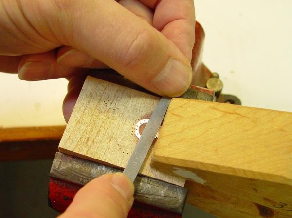
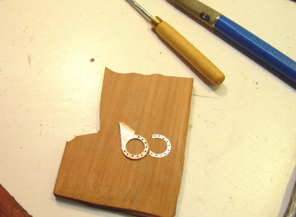

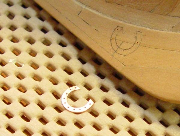
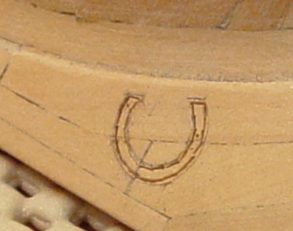

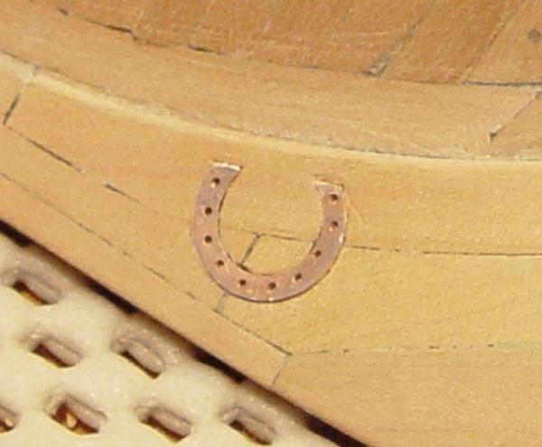
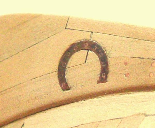
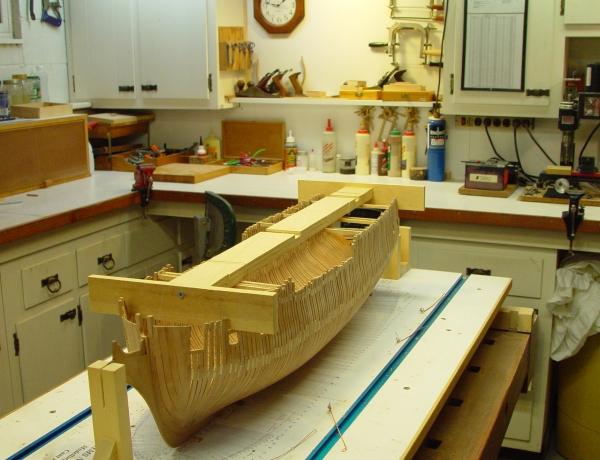

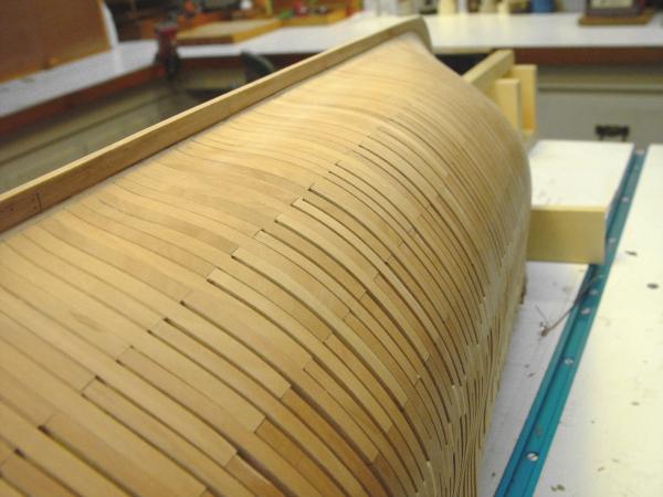
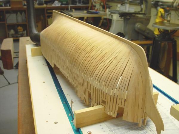
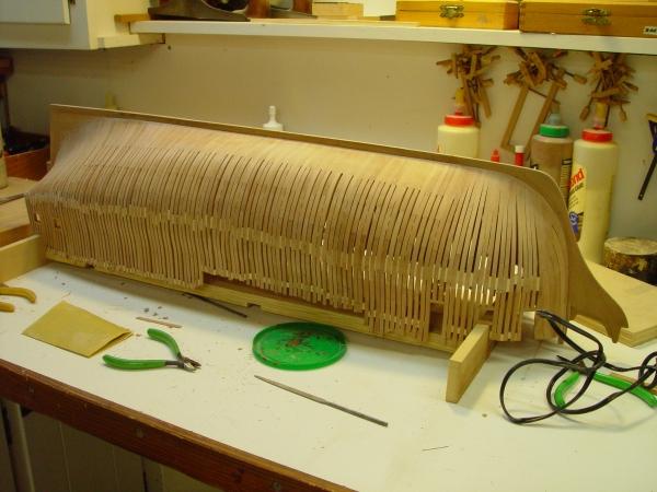
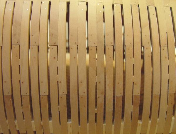

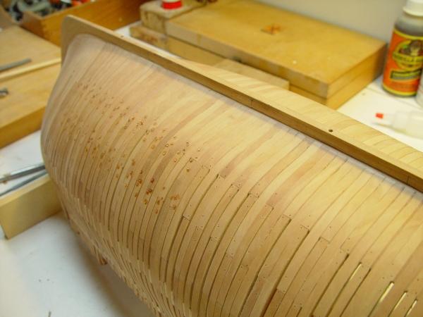
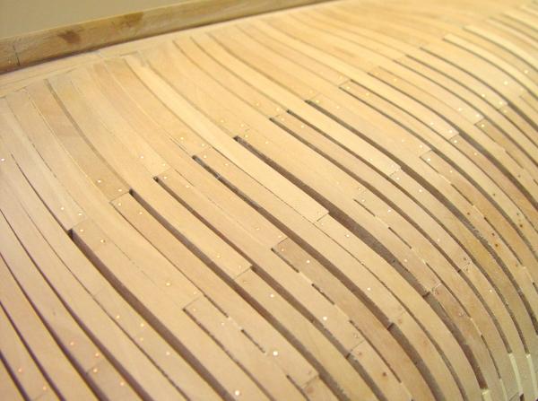
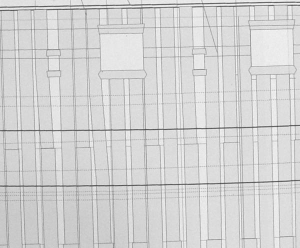

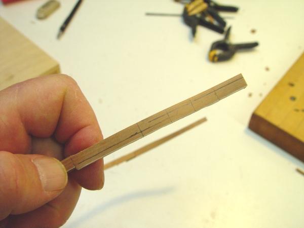


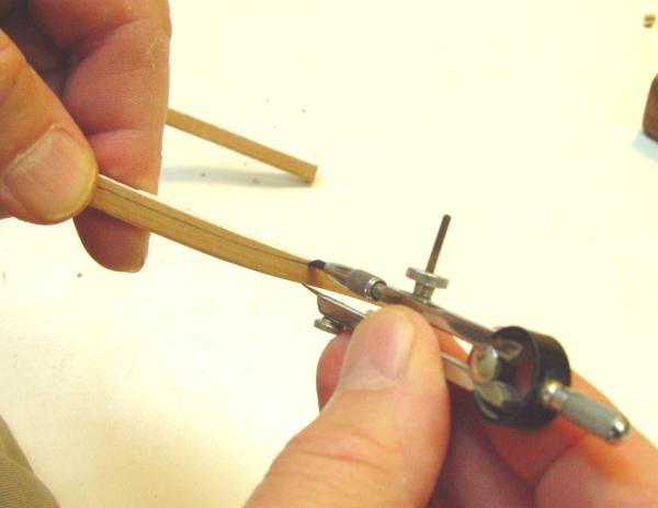

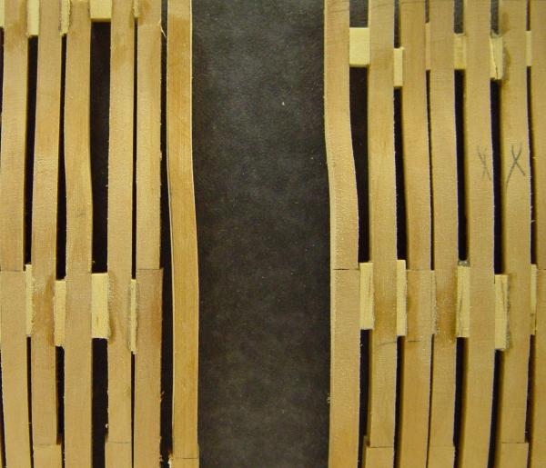

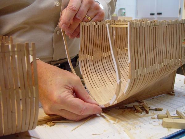

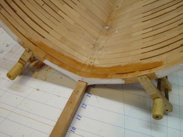
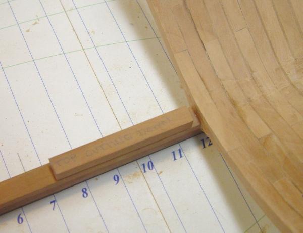


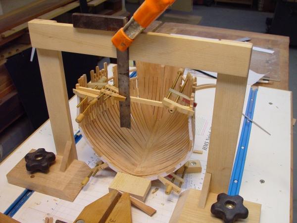


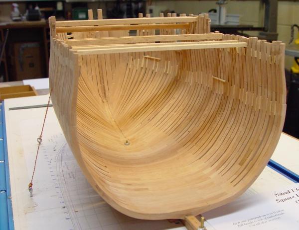
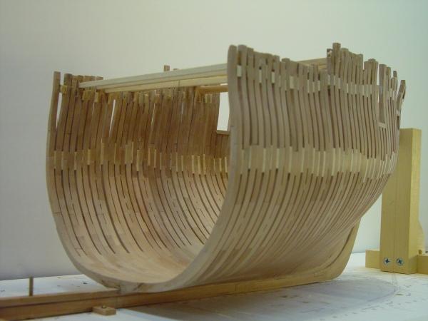

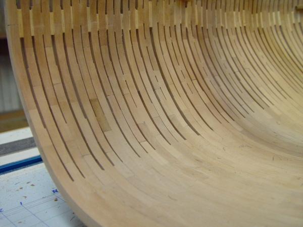


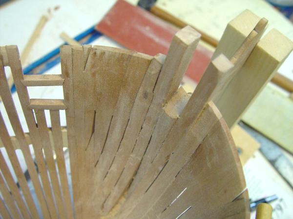
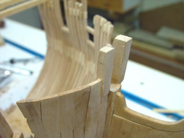
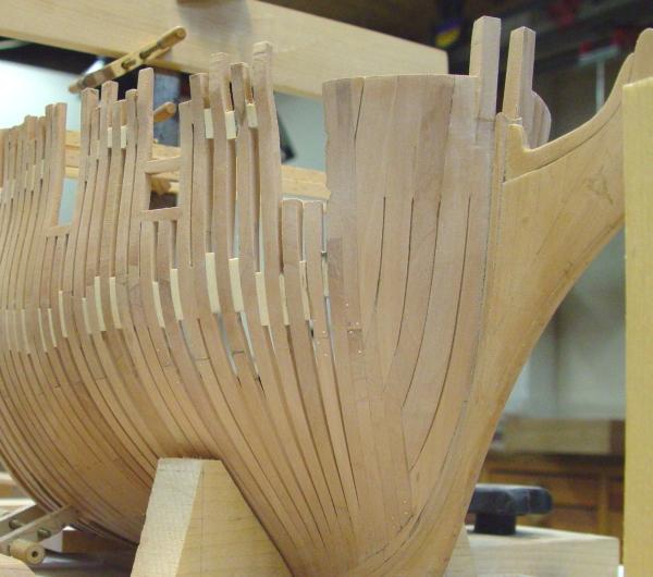
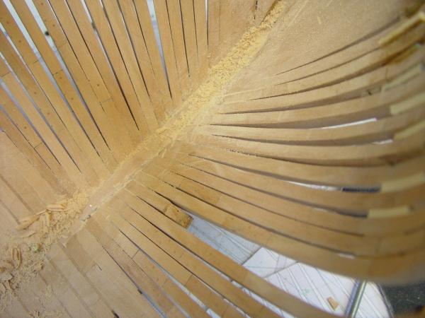
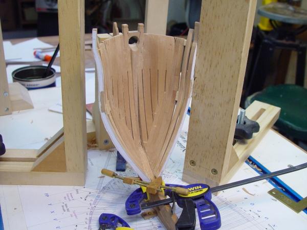


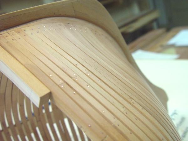


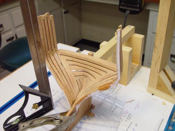

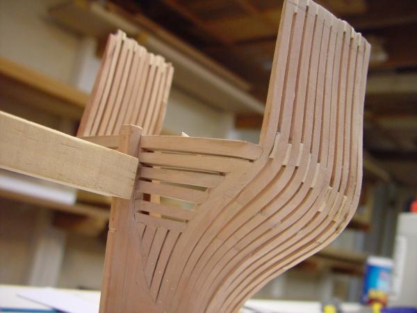
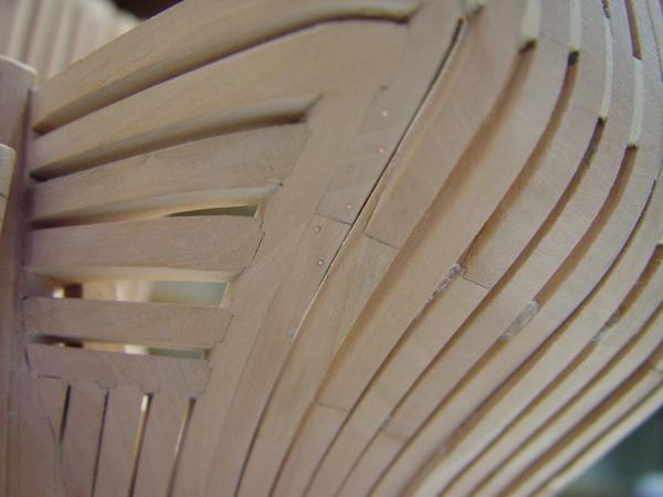

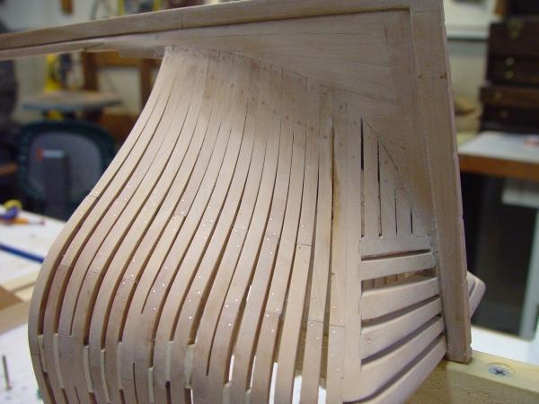

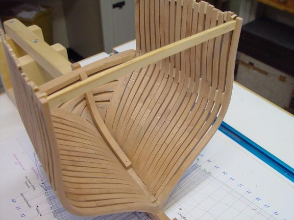
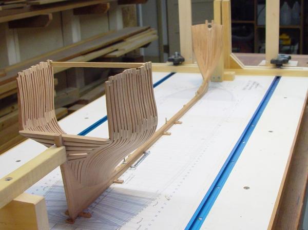

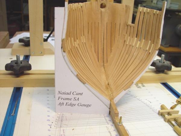


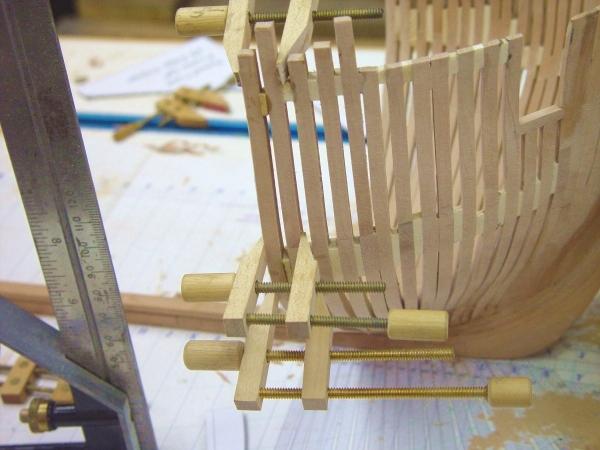
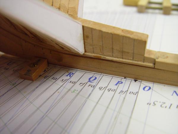
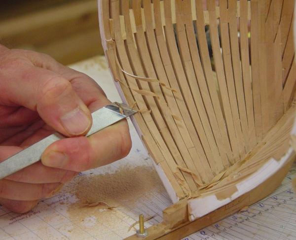

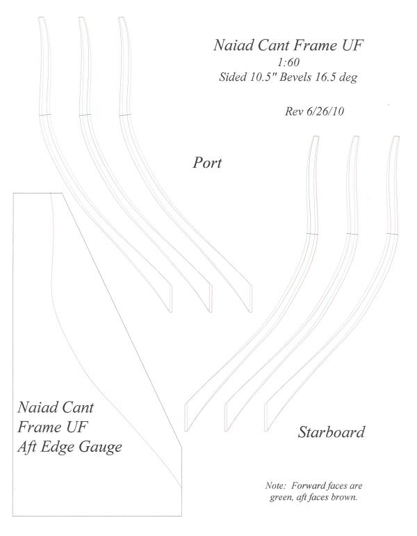

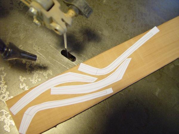
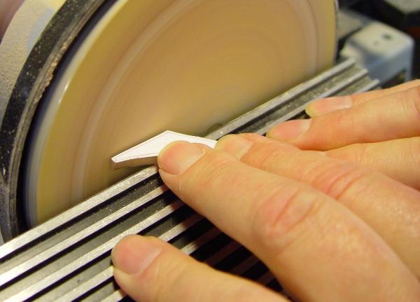
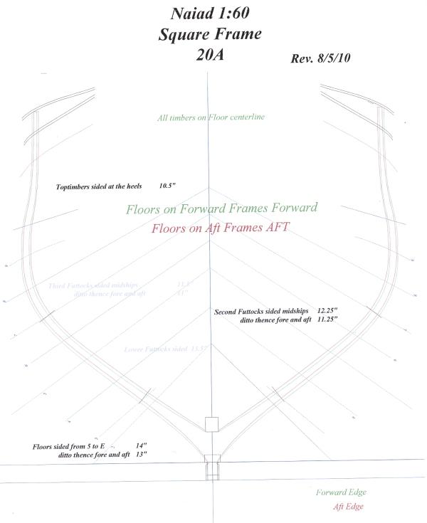
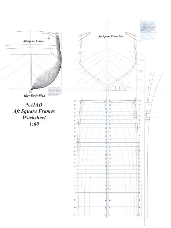
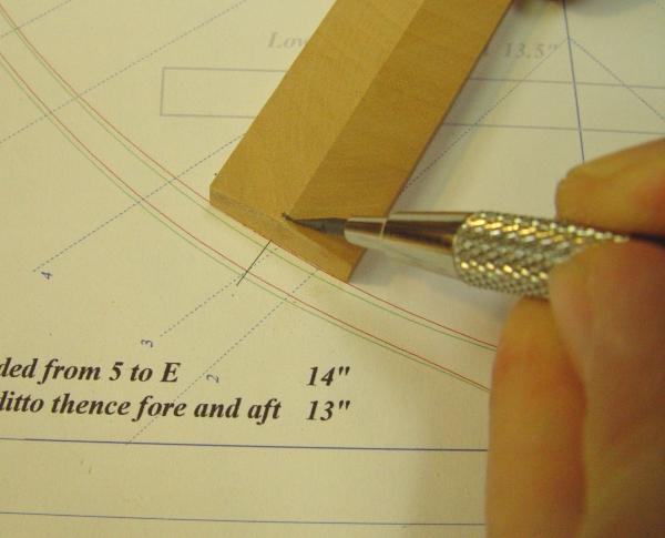


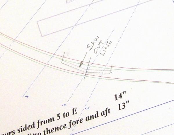


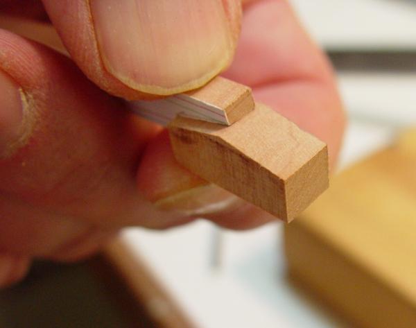
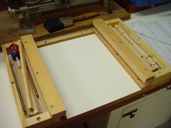
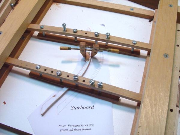


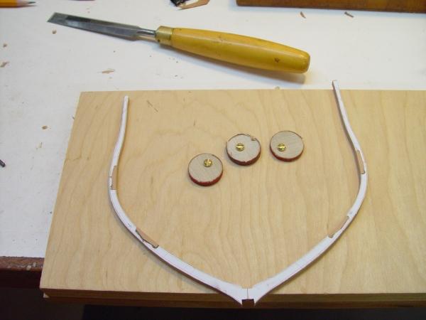

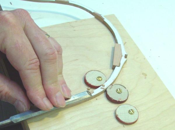
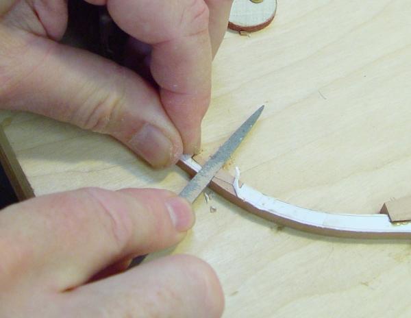
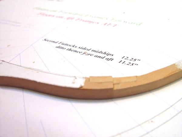
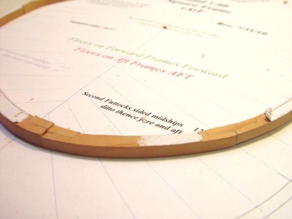

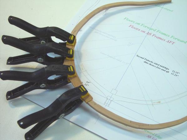
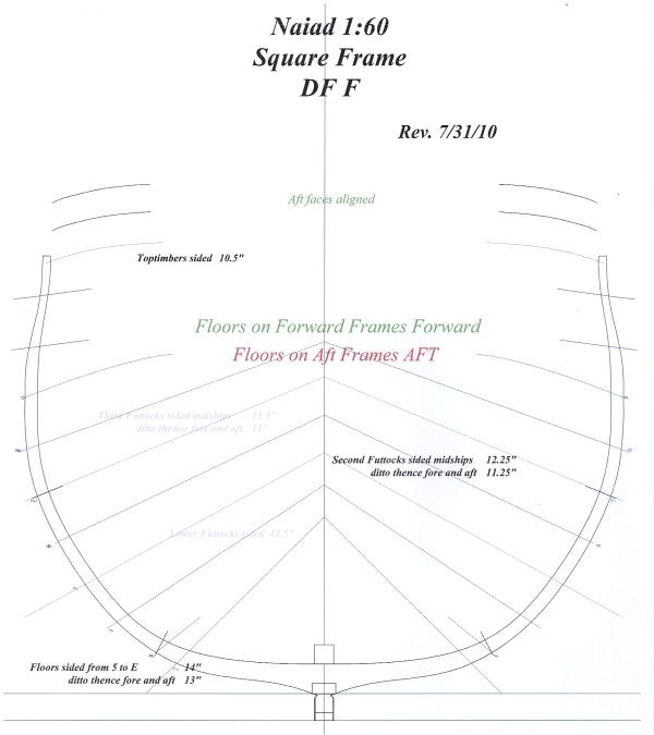

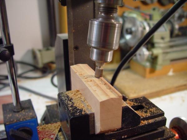

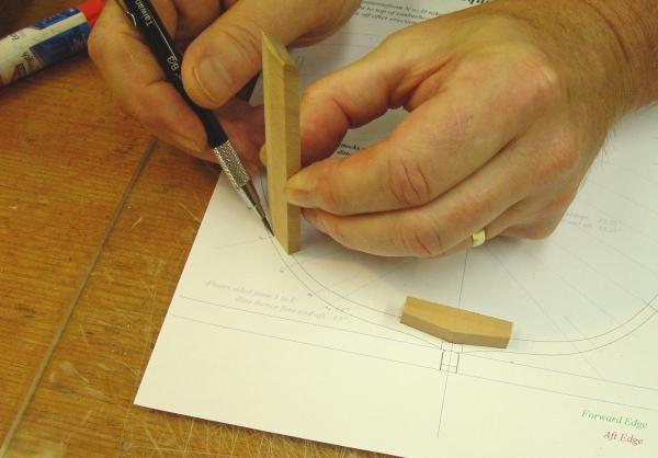

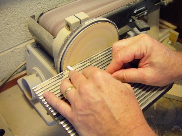
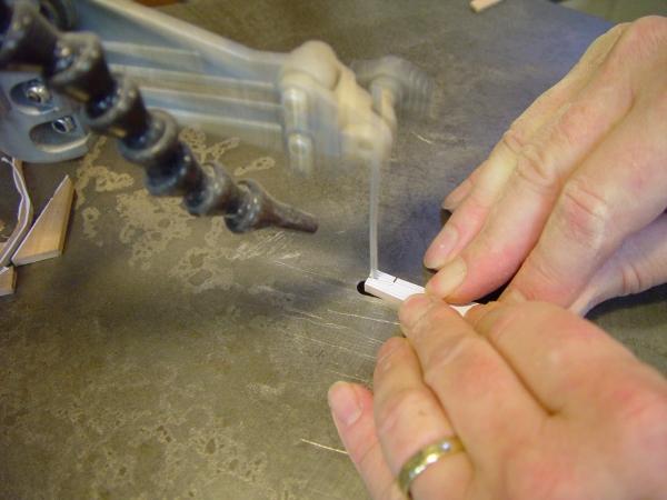
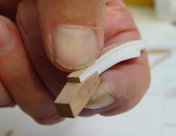


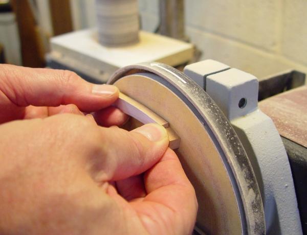


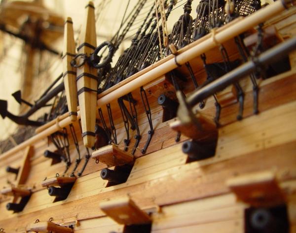

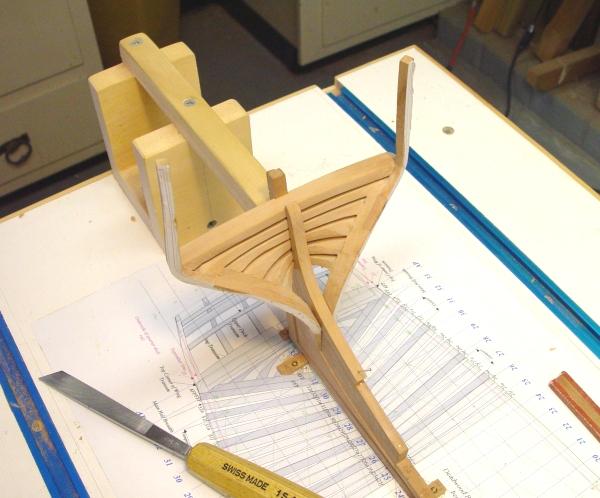
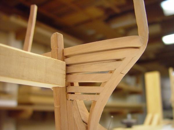


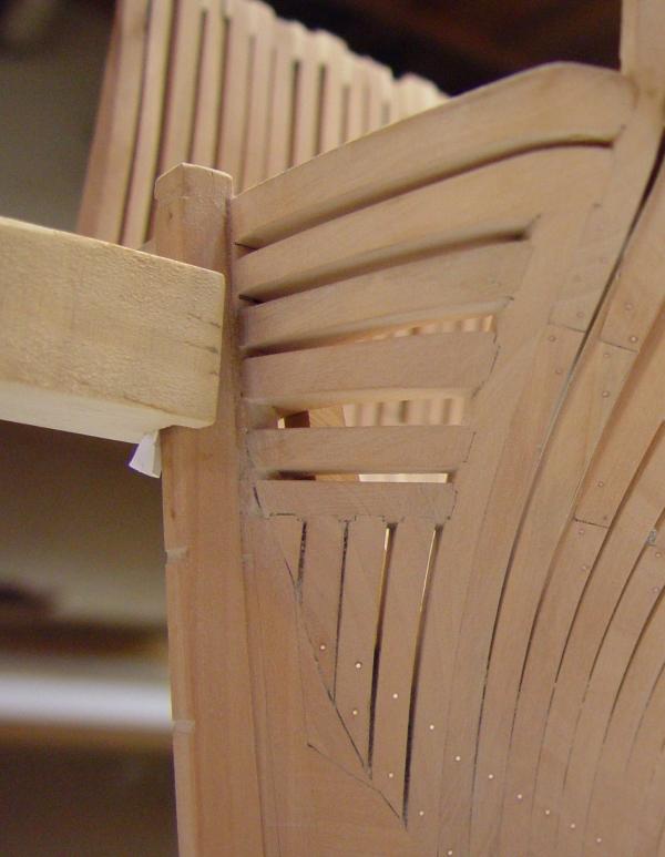

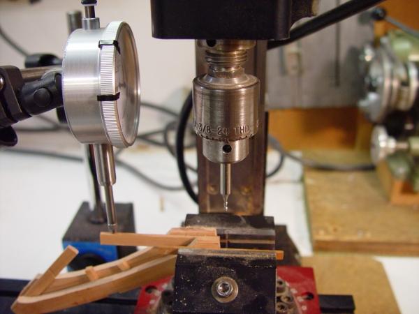

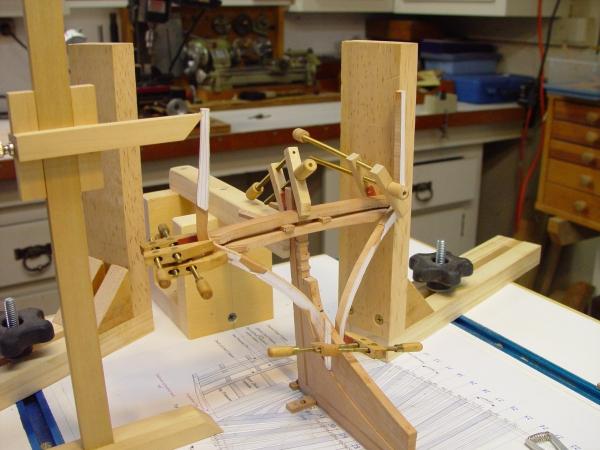
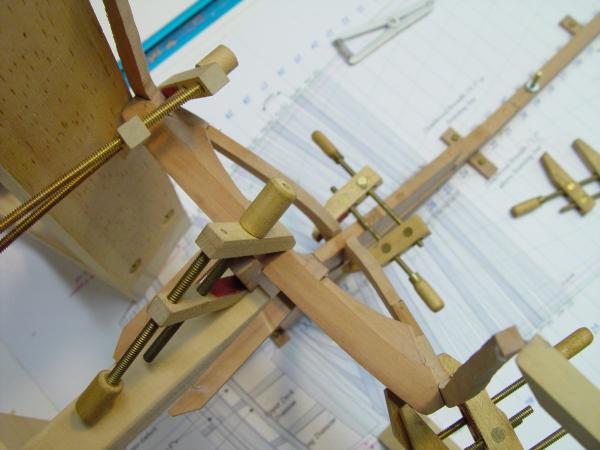
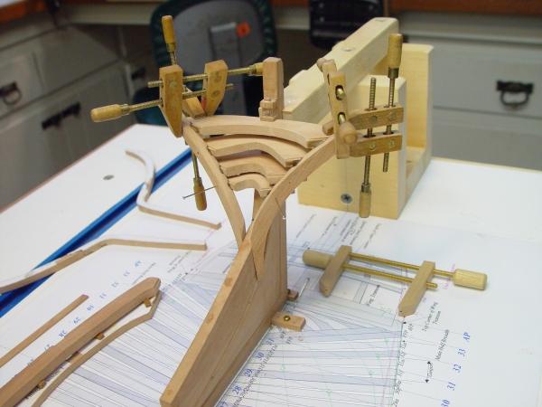
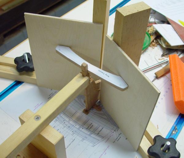
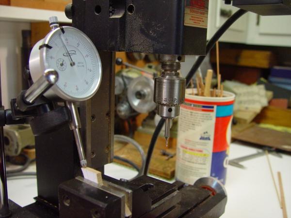
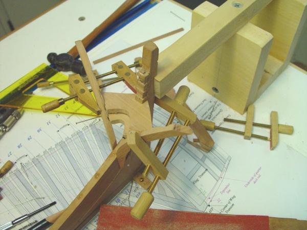
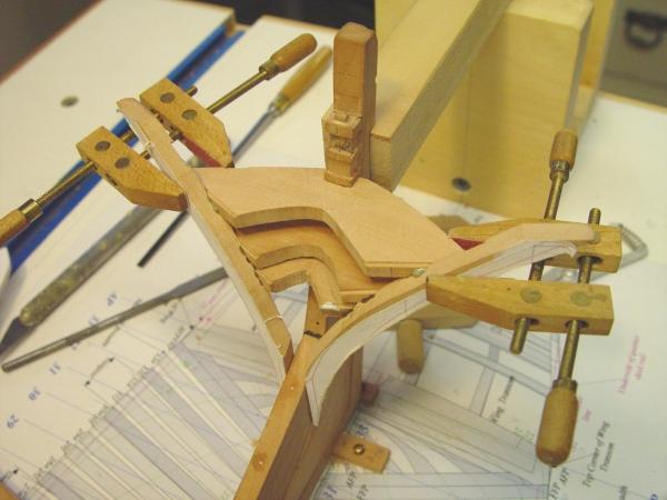


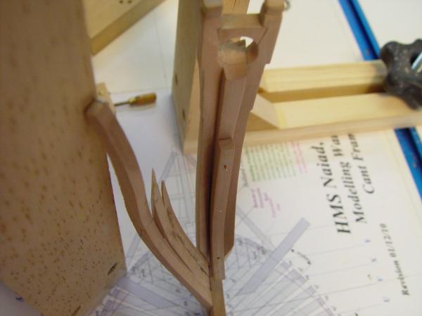


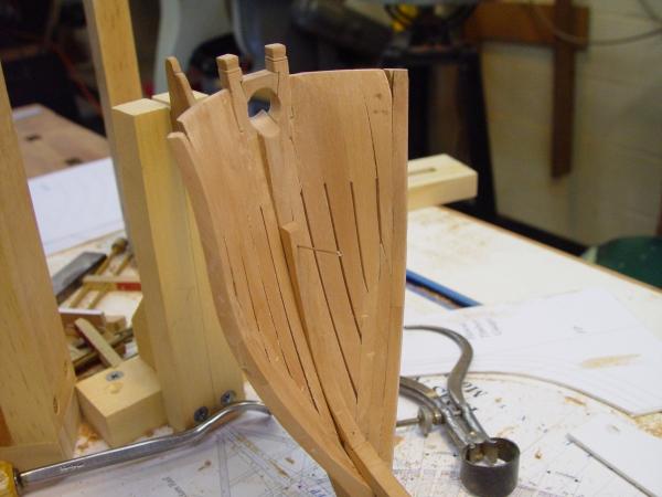
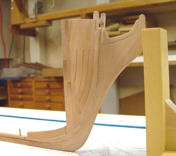

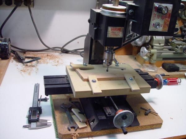

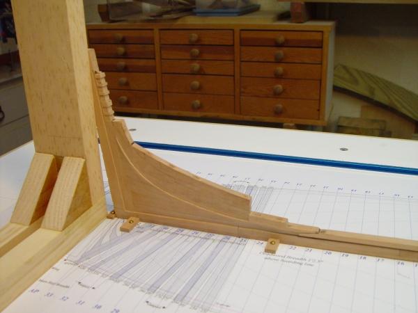


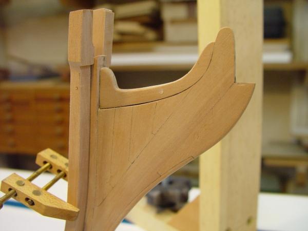
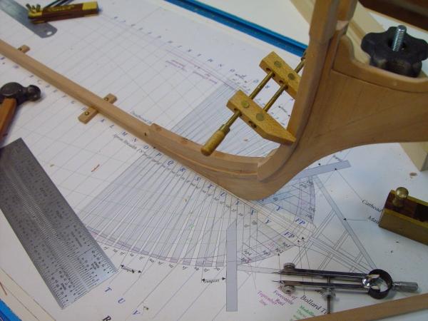
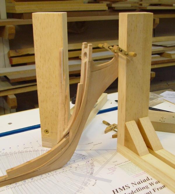
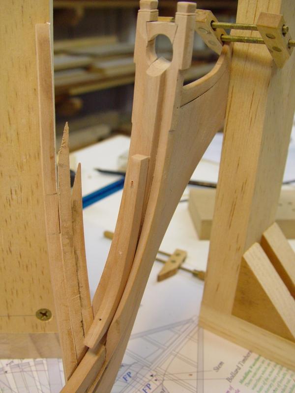
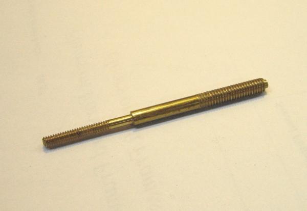
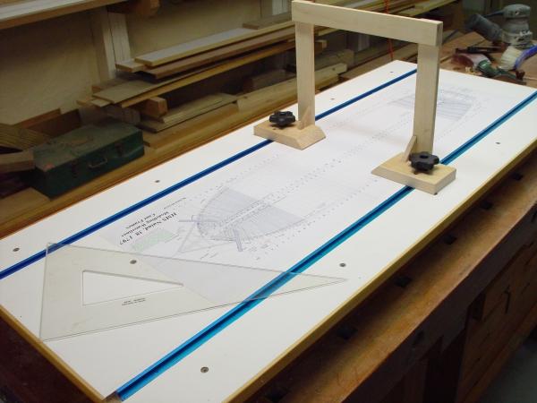
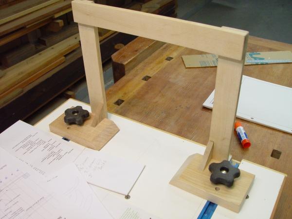

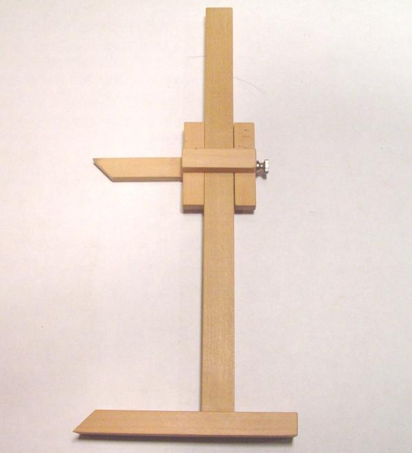

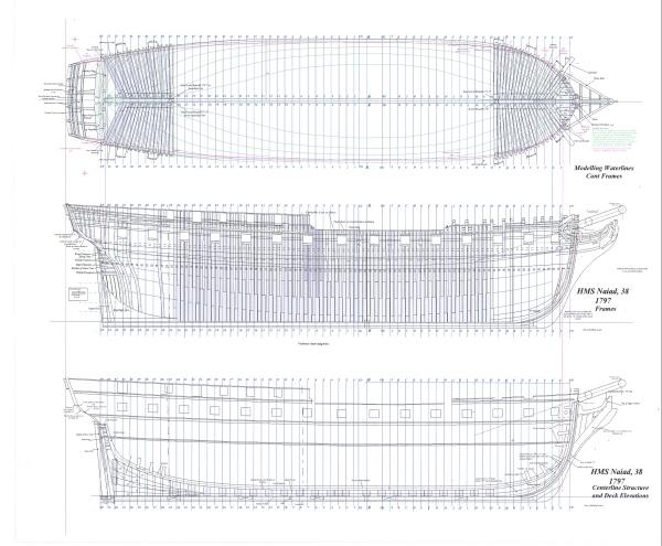
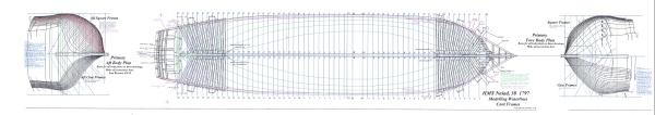
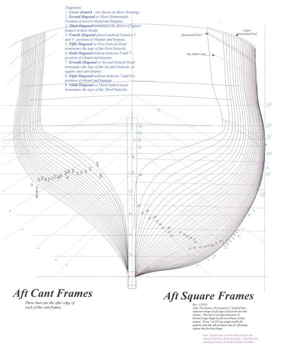
HMS Victory by EdT - FINISHED - 1:96 - POB
in - Build logs for subjects built 1751 - 1800
Posted
Thanks for the comments. Its good to see people are interested in this one again.
Robert: a ribbon, no medal.
Ed