Pete Jaquith
-
Posts
343 -
Joined
-
Last visited
Content Type
Profiles
Forums
Gallery
Events
Everything posted by Pete Jaquith
-
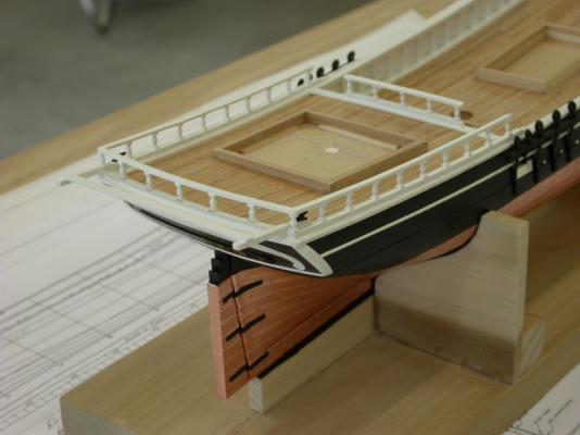
 Welcome to the "Eagle" 1847 build log, Next steps address installation of deadeyes and poop rails. Key points include: >>> Deadeyes were Bluejacket castings >>> Poop rails fabricated from bass strip wood (counter rails fabricated from sheet stock) >>> Poop rail stanctions were Bluejacket castings >>> Rooster tails (boat davit) fabricated from bass strip wood >>> Poop front rail was an addition to original plans Pete Jaquith Shipbuilder
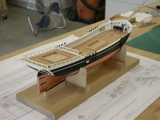
- 82 replies
-
- 15
-

-
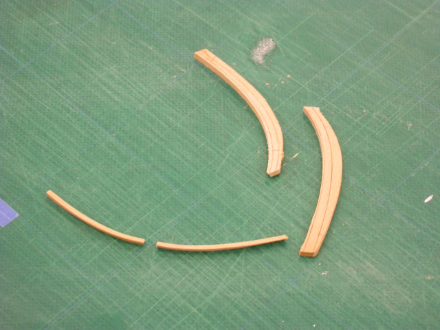
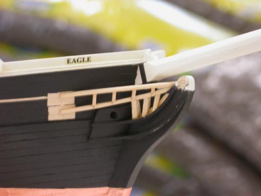
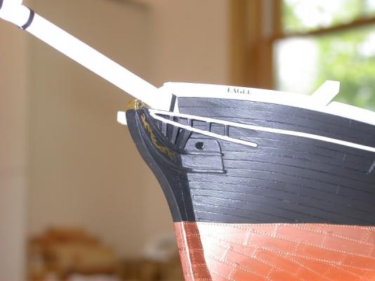
Welcome to the "Eagle" 1847 build log, Next steps include the head rails. Key points include: >>> Head structure fabricated from basswood stock >>> Stem scroll work done with fine gold paint pens >>> LESSON LEARNED - FIT HEAD STRUCTURE BEFORE HULL PAINTING Pete Jaquith Shipbuilder
- 82 replies
-
- 10
-
-
Floyd, It good to hear from old friends! Regards, Pete
-
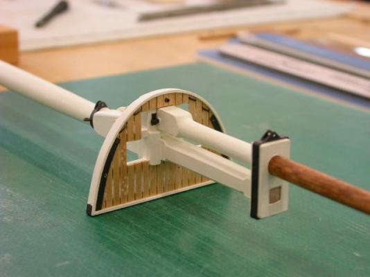
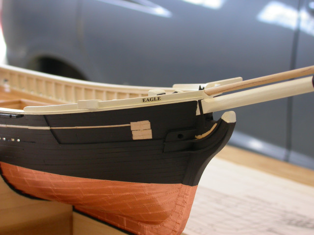
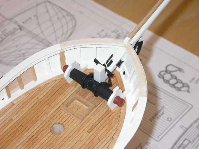
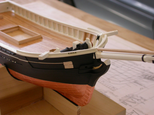
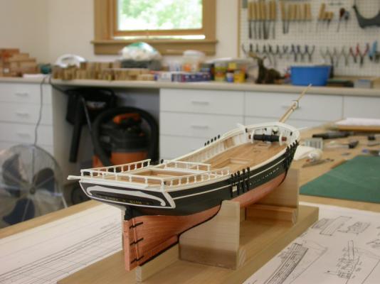
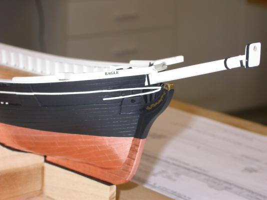
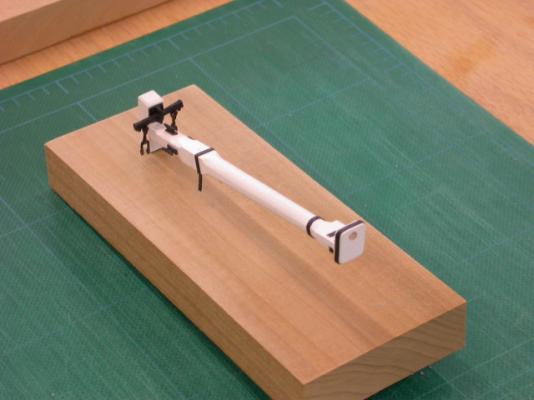
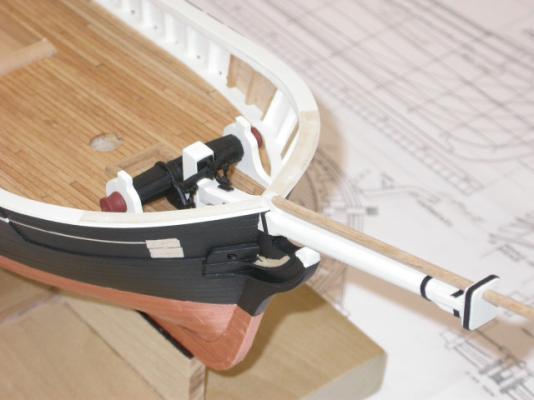
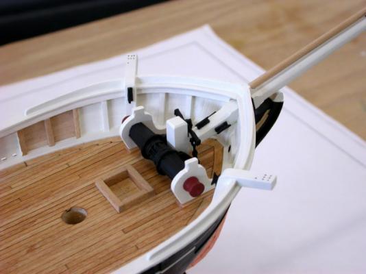
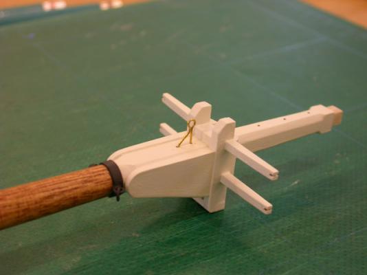
Welcome to the "Eagle" 1847 build log, Next steps include installing the bowsprit, Samson post, anchor windlass, spray rails, etc. Key points include: >>> Bowsprit setup with cap bands, cleats, etc. >>> Bowsprit sub-assembled with Sampson post and anchor windlass components >>> Bowsprit sub-assembly fitted >>> Anchor windlass fitted >>> Foward cap rail sections fitted >>> Catheads fitted >>> Spray rails fabricated / fitted from basswood sheet stock >>> Ship's name fitted on spray rails Pete Jaquith Shipbuilder


-
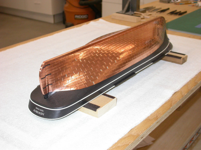
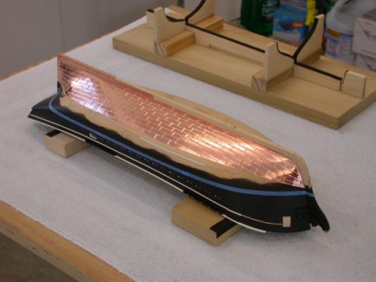
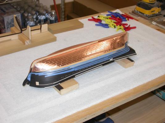
Welcome to the "Eagle" 1847 build log, Continuing with copper sheathing installation. Pete Jaquith Shipbuilder


- 82 replies
-
- 14
-
-
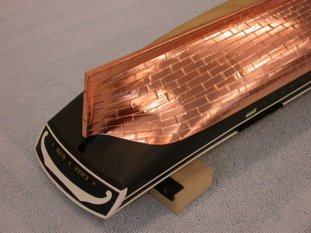
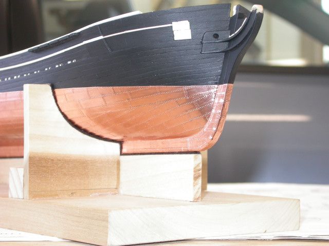
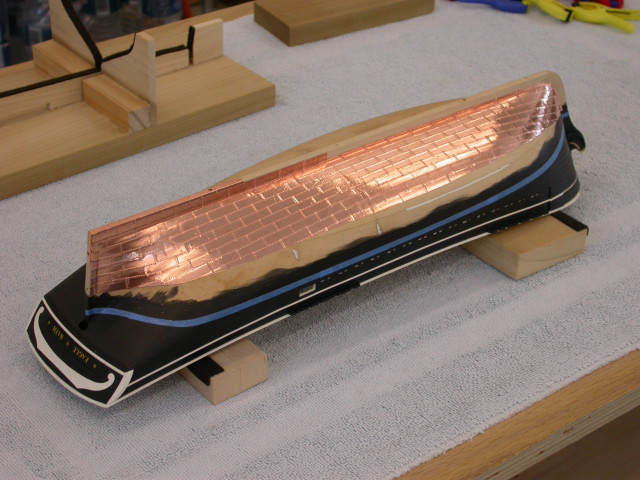
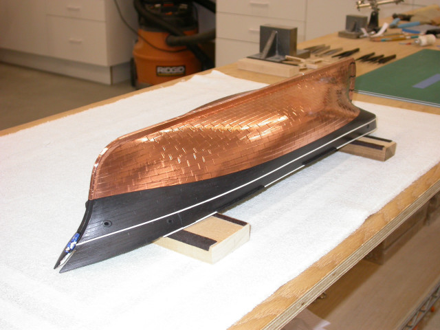
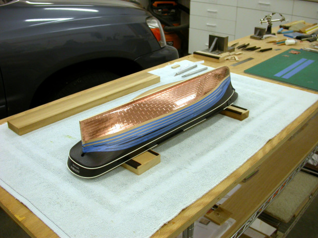
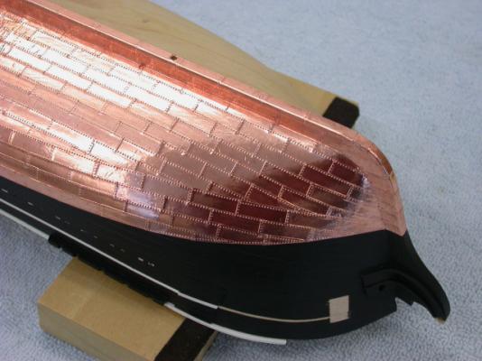
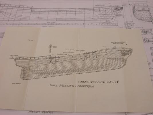
Welcome to the "Eagle" 1847 build log, Next steps include the design and installation of copper sheathing. Key points include: >>> Copper layout includes upper/lower gore strakes with no WL dressing belt (typical of small trading and whaling vessels) >>> Copper layout similar to whaling Brig "Cate Cory" >>> Copper plates 1/4" x 3/4" (16" x 4' 0") copper tape cut on rotary card cutter >>> Copper plates embossed on two edges with fine pounce wheel >>> Waterline located with use of surface guage >>> Blue painters tape strips used to layout/guide plate installation >>> Plates cut to shape at gore and waterlines >>> Some trimming of plates required at WL under counter >>> LESSON LEARNED - Brigantine "Newsboy" 1854 COPPERED WITH PLAIN PLATES; I PREFER THAT LOOK OVER EMBOSSED PLATES Pete Jaquith Shipbuilder
-
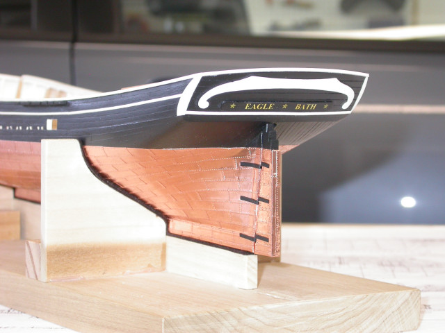
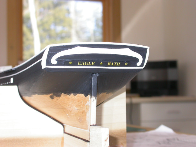
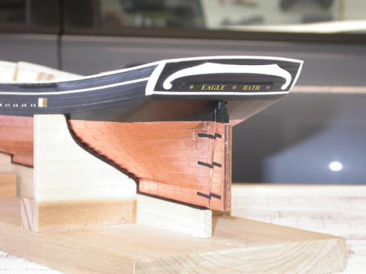
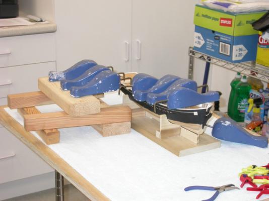
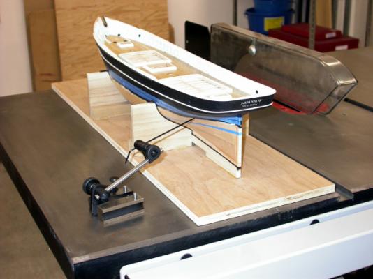
Thank you for your interest in "Eagle" 1847, Work continues on bulwark/hull painting, cap rails, trim pieces, etc. Key points include: >>> Inner bulwarks painted (unpainted areas left for fore staysail horse and catheads) >>> Exterior bulwarks/upper hull painted >>> Cap rails/poop planksheer painted/fitted >>> Forward caprail pieces left loose for bowsprit installation >>> Thick pads for rooster tails (boat davits) fitted >>> Bulwark molding trim painted/fitted >>> Transom molding trim/fancy piece painted/fitted >>> Ships name/hailing port installed on transom >>> LESSONS LEARNED - FUTURE BUILDS, HEAD RAILS SHOULD BE FITTED PRIOR TO HULL PAINT >>> LESSONS LEARNED - FUTURE BUILDS, WHITE FOR SHIP's NAME/HAILING PORT WOULD STAND OUT BETTER Pete Jaquith Shipbuilder

- 82 replies
-
- 17
-
-
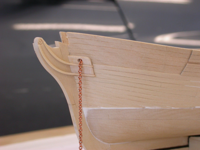
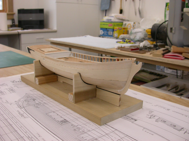
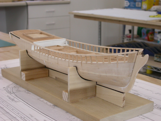
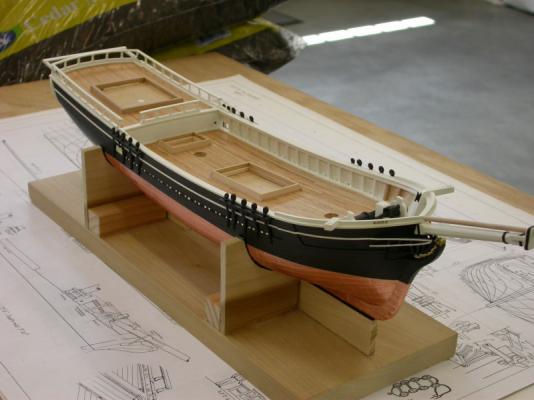
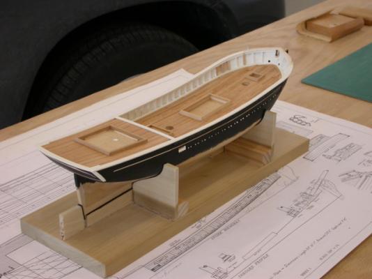
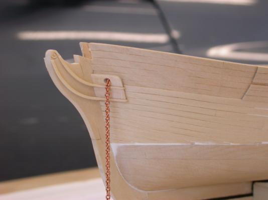
Welcome to the Topsail Schooner "Eagle" 1847 build log, Continuing with hull planking; key points include: >>> Double timberheads fitted in way of catheads >>> Bulwark and upper hull planking continued to below copper line >>> Joint between planking and hull block faired with wood filler >>> Anchor stowage pad installed on forward bulwarks (note gap for trim molding) >>> Anchor bolsters/inner pads fitted >>> Trim moldings fitted from stem to anchor bolsters >>> Hause pipes drilled out >>> Chain plates fitted with assistance of temporary mast Pete Jaquith Shipbuilder

- 82 replies
-
- 12
-
-
Thank you for your interest in "Eagle" 1847, Additional pictures of bulwark and upper hull planking. Key points include: >>> Forward bulwark/hull planks have a significant downward curve when expanded >>> Curved planks cut with a single edge razor blade and ships curves >>> Hull planking extends ~1/8" below the waterline (copper line) >>> 1/32" bulwark and 3/64" hull planks leave a slight ledge at the deck at side (typical of the period) >>> Allowance made for 3/64" half round white bulwark molding (to be added after painting) >>> Lower bulwark plank include slots for scuppers Regards, Pete Jaquith


- 82 replies
-
- 12
-
-
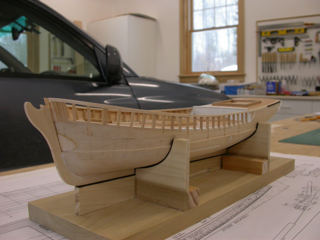
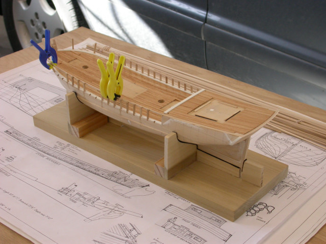
Thank you for your interest in "Eagle" 1847, With deck planking complete, next steps are transom planking, bulwark framing, and upper hull planking. Key points include: Transom Planking >>> Transom planking was cut from 3/64" sheet stock to provide the expanded shape >>> Fancy pieces were final shaped in place >>> Transom planking was sequenced prior to hull/bulwark planking Bulwark Framing >>> Planksheer/covering boards were fabricated with slots for timberheads >>> Every 3rd timberhead was slotted into hull block; slots were easly cut with a sharp razor blade and fine chisel >>> A single inner plank and upper bulwark plank were used to fair the timberheads >>> Space between above planks filled with sq stock to provide a solid base for cap rails >>> Bulwark planks 1/32" x 3/32" >>> Hull planks 3/64" x 1/8" >>> LESSONS LEARNED - SLOT EVERY TIMBERHEAD INTO THE HULL BLOCK (every 2nd will work on side) >>> LESSONS LEARNED - LEAVE ADDED MATERIAL ON THE FORWARD TIMBERHEADS TO FAIR IN PLACE Pete Jaquith Shipbuilder


- 82 replies
-
- 11
-
-
Sal, Once you have the copper sheathing designed, copper plating actually goes quite quickly. If you are satisfied with copper tape, the above process works well for me. I would anticipate that "Phantom" would have a similar layout to "Newsboy" but adjust your plate size for the scale. Pete Jaquith Shipbuilder
-
Thank you for your interest in "Newsboy" 1854, As you have likely noticed. I enjoy the hobby and I have enjoyed My "Newsboy" 1854 build. In response to your questions: >>> I am currently using Floquil acrylic paints. I apply them directly over Floquil's acrylic primer (either white or gray as the color dictates). I prepared a number of test pieces to evaluate various paints and colors for my projects. >>> I prepared the ship's name and hailing port with Adobe Photo Shop (I have also used Word). I do a series of trials to get the appropriate expanded shape and then to get the background to match the warm white and engine black paint I am using. I print the names on fine printer paper, seal them with Krylon spray, and glue them in place with white glue. Finally, I seal them with wiping varnish. As you have likely found, you need a fair amount of curve (camber) on your stern lettering to look correct on the raked / curved transom. >>> Reference material for mid-1800 sailing vessels: >>>>>> Approximately 24 plan sets/instruction manuals for vessels of the period (Model Shipways, Bluejacket, A.J. Fisher, Maine Maritime Museum, Mystic Seaport Museum, New Bedford Whaling Museum, etc.) >>>>>> Crother's book on the Americal Clipper Ship Design >>>>>> Harold Underhill's book on Plank on Frame Ship Models (somewhat later period) >>>>>> Various rigging books (some from an earlier period but they help in identifying the range and approximate size of rigging lines) Thanks for your interest, Pete Jaquith Shipbuilder
-
Mike, Very nice work. I will look you up when I am back in San Diego. I am currently working on a 1:1 scale shipbuilding project in North Vancouver, BC Canada. Pete Jaquith Shipbuilder
- 55 replies
-
- 1
-
-
- 18th century longboat
- model shipways
- (and 1 more)
-
Brett, I use Minwax's oil based wipe on varnish (satin finish) for sealing the exterior hull planking/copper sheathing after all attachments are complete. I use a somewhat thicker Bartley's oil based gell wiping varnish for sealing/finishing decks. I tried the water based products and was dissatsified with the results. I do, however, use water based acrylic paints. Pete Jaquith Shipbuilder
-
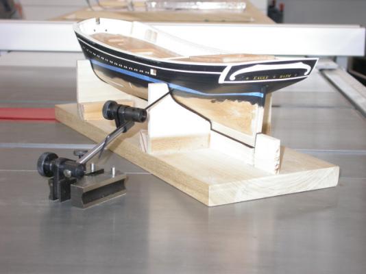
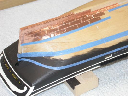
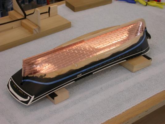
Various techniques including copper paint, individual copper plates, photo etched plates, and self adhesive copper tape have been used by ship modelers to simulate the copper sheathing used for under water hull protection on both naval and merchant ships from the late 1700’s thru the late 1800’s. The following notes describe the technique selected for my Topsail Schooner "Eagle" of 1847 build. Test Pieces – Test pieces were prepared to evaluate the installation process and appearance of various methods including individual plates, individual plates cut from self adhesive tape, strips of copper tape, and both plain and embossed plates. The selected approach was individual plates cut from self adhesive copper tape with embossed nail heads on the exposed plate edges only. Copper Material – The material used for copper sheathing was .0015” x ¼” wide self adhesive copper tape purchased from Blue Jacket Ship Crafters. Plate Fabrication – The individual copper plates were cut from self adhesive copper tape using a Carl Rotary Trimmer from Staples Office Supply. The plates were ¼” x ¾” (16” x 48” full size at 1:64 scale). The individual plates were then embossed from the back side using a fine pounce wheel. Hull Preparation – After filling and sanding any minor dings, holes, etc. on the lower hull and completion of topside painting (acrylic paints); the topside and bare lower hull were sealed with three coats of Minwax Wipe-On-Poly (oil based wiping varnish). A hard smooth surface is necessary for tape adhesion, and a smooth surface is important as any defects will show through the thin copper foil. Hull Layout – With the model resting in its building cradle, the waterline was laid out using a surface gauge. The gore line was then located using the copper sheathing layout taken from a similar size merchant hull plans (whaler "Kate Cory"). The plate layout consists of upper and lower gore strakes with no dressing belt. The individual copper plate strakes were laid out using a tick strip working up from the keel. The water line, gore line, and individual plate strakes were then marked on the model hull using narrow strips of blue masking tape. Note that properly locating the waterline and gore line are critical as I have seen models where they dip down badly in the stern area. Plate Installation – Individual copper plates were applied using the masking tape strips as a guide and working from the keel up and the stern post forward. The plates were overlapped approximately 1/32” and butts were staggered like brick work. A fair amount of fitting was required in the upper stern area due to the hull shape, and the upper corners of the plates were cut off for those plates that crossed the gore line and waterline. After installation, all copper foil plates were rubbed down with a soft rag. Protective Finish – After installation, I cleaned the copper plates with denatured alcohol and applied three coats of Minwax Wipe-On-Poly to seal and protect the copper surface. After approximately 10 months, the copper sheathing is beginning to show some tarnish under the varnish finish. On future builds, I may just choose to clean the copper plates and let them tarnish naturally. While the above technique is only an approximation of full size practice as the nail pattern would have covered the complete plate and would hardly be visible at this scale, I was pleased with the overall effect. As noted; critical items in the application include having a smooth hard surface, layout of the waterline/gore line, and holding the plate strakes straight. Brigantine "Newsboy" 1854 Installation – Following completion of the Topsail Schooner "Eagle", my next ship model was the Brigantine "Newsboy" of 1854 (also in 1:64 scale). The copper sheathing installation on "Newsboy" was similar to "Eagle" with the following exceptions: 1. Due to her finer hull lines, I chose to model the copper sheathing layout after the clipper ship "Flying Fish" of 1851. The copper sheathing layout consisted of an upper and lower gore with a single dressing strake at the water line. 2. The copper plate fabrication and installation was similar to "Eagle". Based on the recommendation of friends at the USS Constitution Model Shipwrights Guild, I elected not to emboss the copper plates with simulated nails. I was pleased with the result, and plan to follow this practice on future models of American Merchant Sail from the mid 1800’s. The following pictures illustrate copper sheathing installation on the Maine Topsail Schooner "Eagle" 1847 and Brigantine "Newsboy" of 1854. Pete Jaquith Shipbuilder


- 24 replies
-
- 28
-
-

-
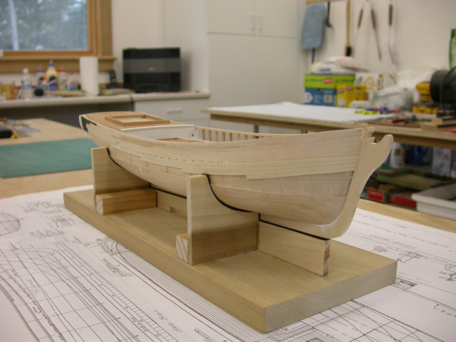
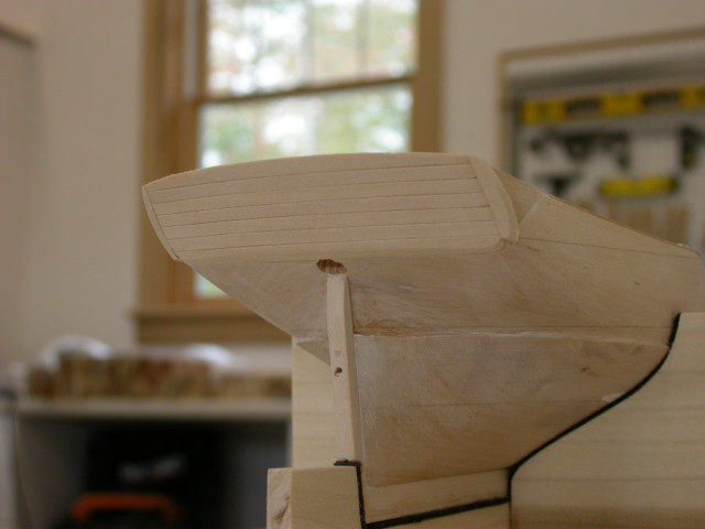
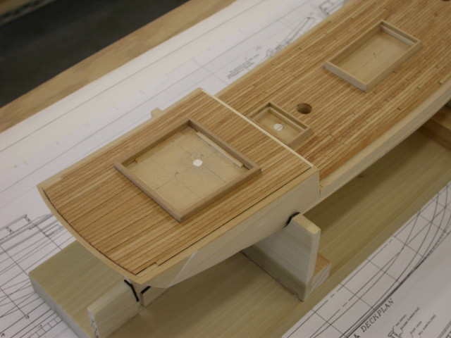
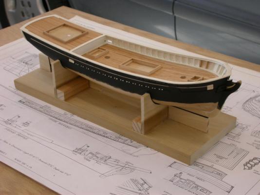
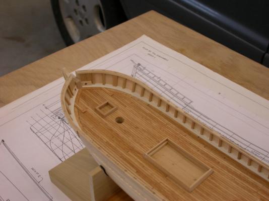
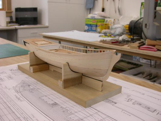
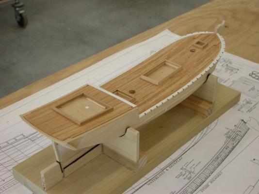
Continuing the "Eagle" 1847 build log, With the main deck planking fitted, I continued with the poop bulkhead and poop deck planking. Key points include: >>> Poop deck planking was fitted with a tapered king plank (planking parallel to deck at side and house coaming, change from the model plans as this was typical of the period) >>> Provision made for poop deck margin planks and thick planks for rooster tails (boat davits) >>> Deck planking stained with oil stain and finished with wiping varnish >>> After painting, poop bulkhead coaming and planksheers were installed >>> Poop bulkhead was planked and painted >>> Poop deck scuppers were fitted (fine brass tubing) Next steps will include planking the transom and constructing the built up bulwarks. Then the construction sequence will be similar to "Newsboy" 1854. Pete Jaquith Shipbuilder

- 82 replies
-
- 13
-
-
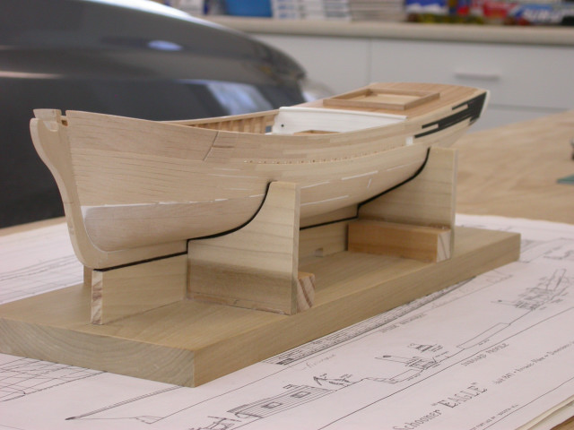
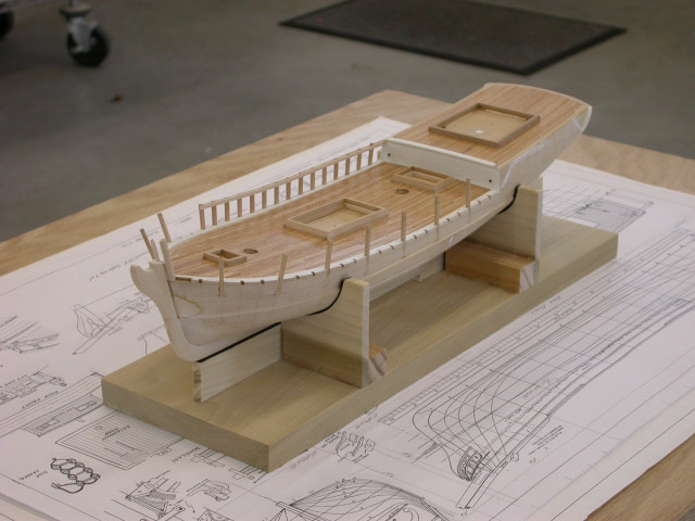
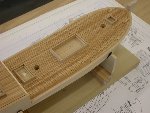
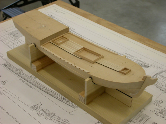
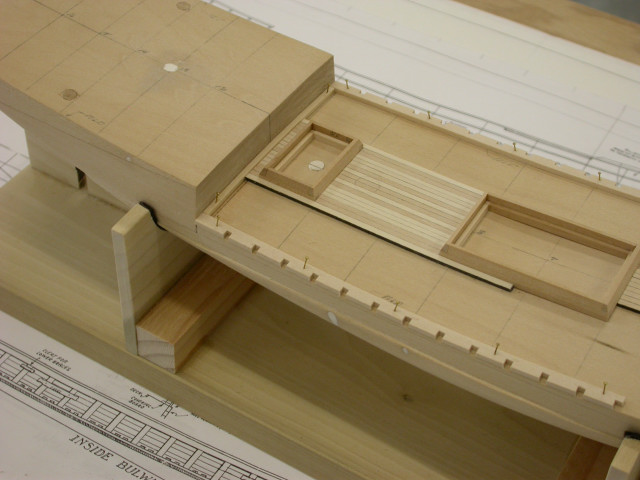
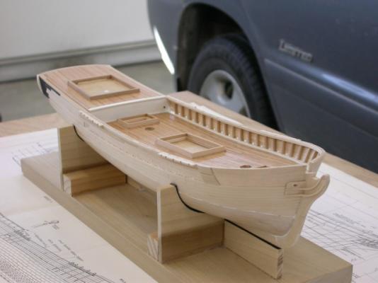
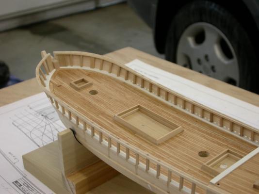
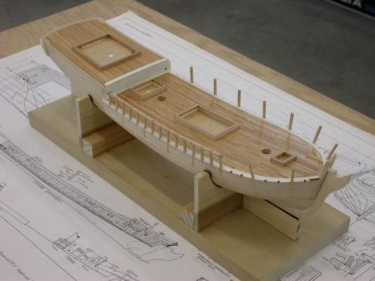
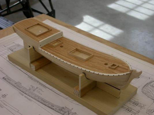
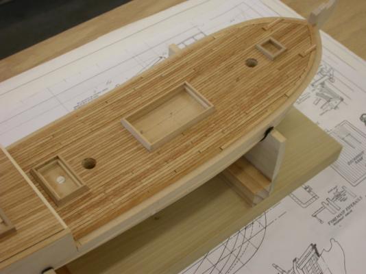
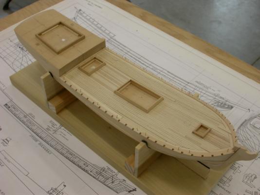
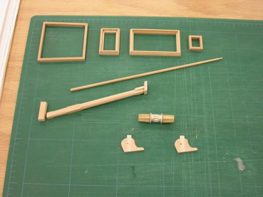
Welcome to the Topsail Schooner "Eagle" 1847 build log, With the hull block prepared, next step is the deck planking. Key points include: >>> Hatch/house coamings, bowsprit, jibboom, and anchor windlass were fabricated 1st as they control the deck planking layout >>> House/hatch coamings were constructed with 1/2 lapped corners >>> Anchor windlass kitbashed from Bluejacket windlass casting kit >>> Deck planking fitted to coamings, poop bulkhead coaming, and planksheer >>> Deck planking nibbed into margin/nibbing strake >>> Thick plank fitted to support anchor windlass >>> Coamings, planksheer, and poop bulkhead coaming will be removed for finishing/paint Note that this sequence is somewhat different than "Newsboy" because of the built up bulwarks. Pete Jaquith Shipbuilder

- 82 replies
-
- 11
-
-
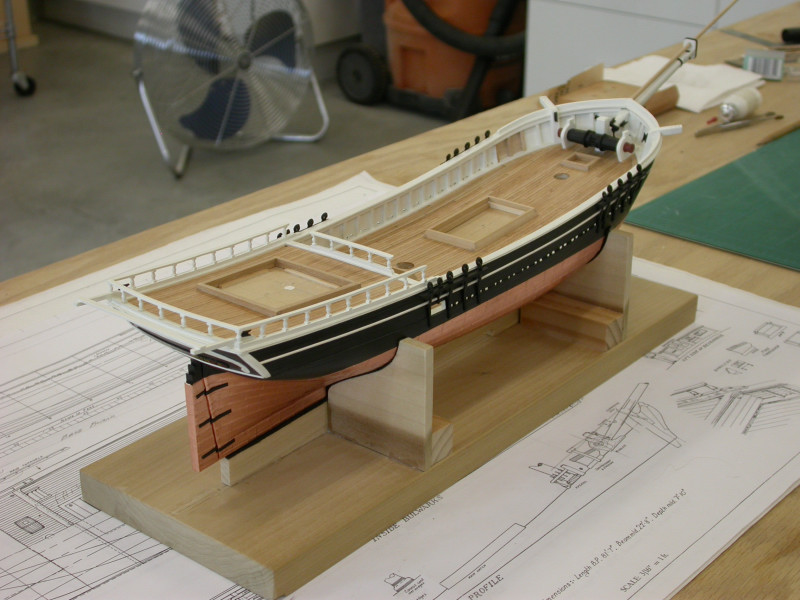
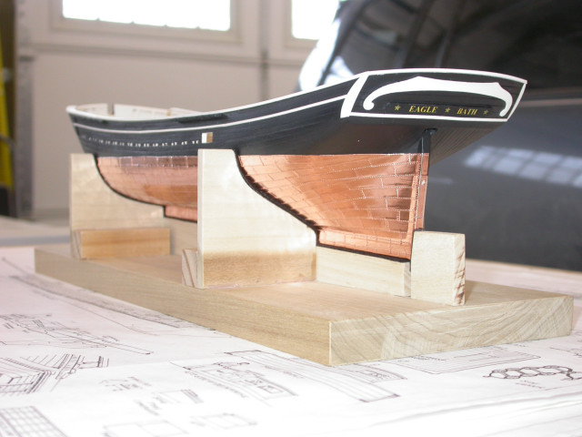
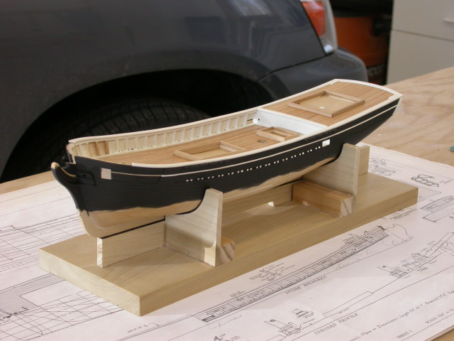
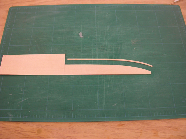
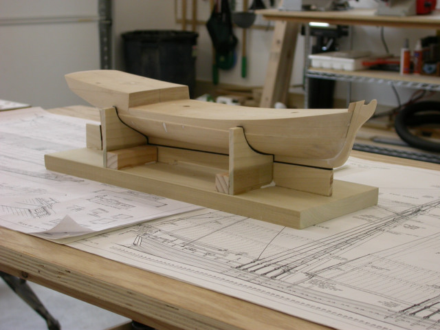
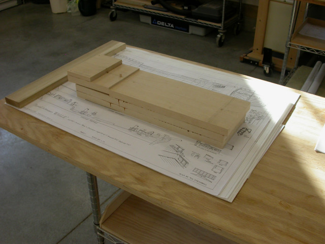
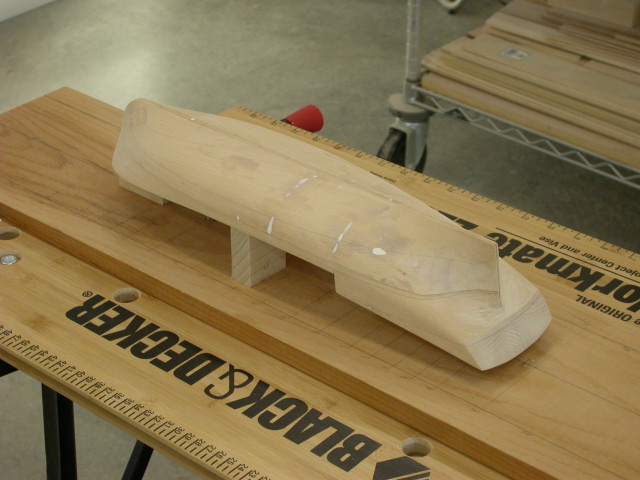
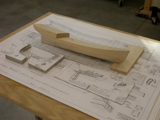
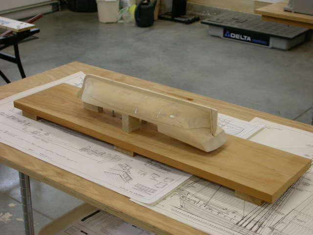
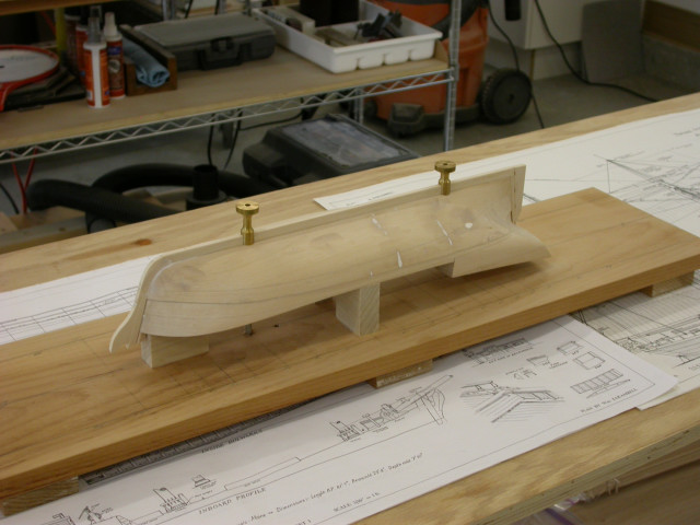
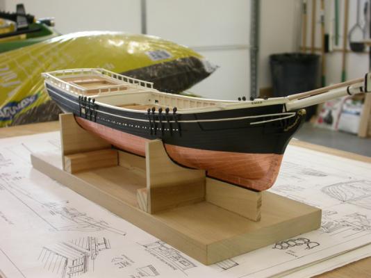
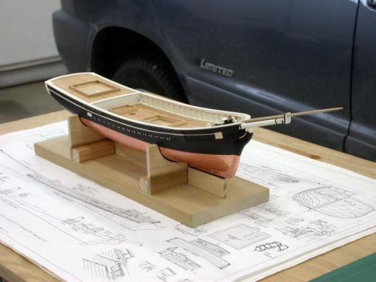
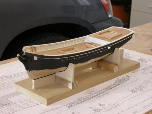
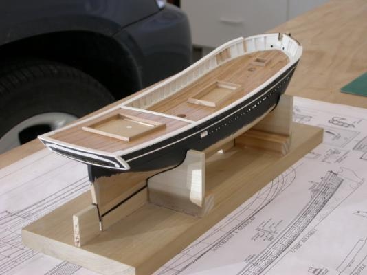
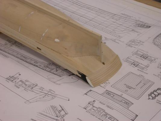
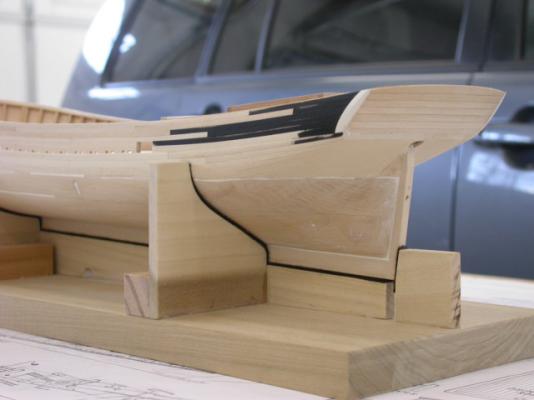
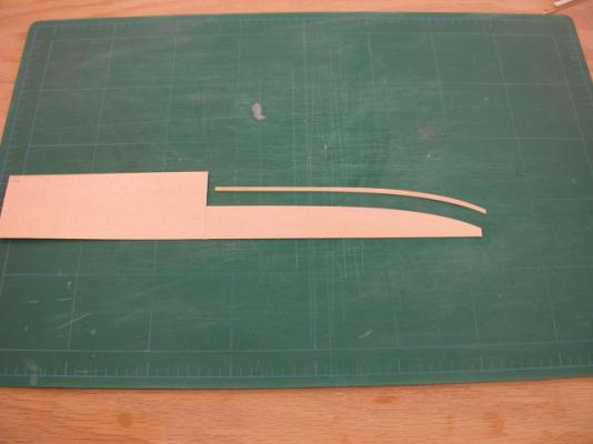
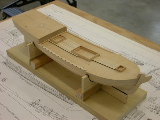
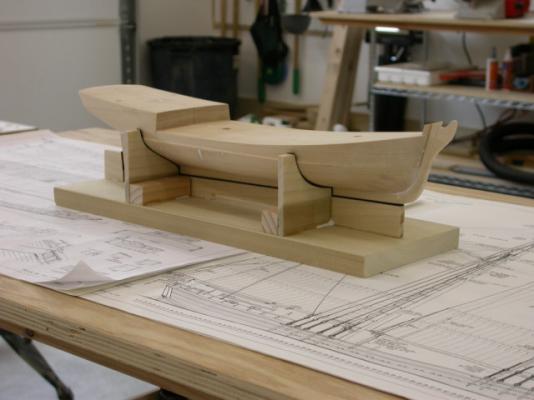
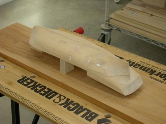
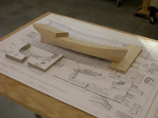
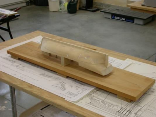
Welcome to Topsail Schooner "Eagle" 1847 build log, The Topsail Schooner "Eagle" 1847 is a 3/16" scale plank on solid scratch build. The construction sequence is similar to my "Newsboy" 1854 build. The hull was carved from basswood laminations. Key Points include: >>> Laminations were glued (dark wood glue) and doweled together >>> Deck shear and camber was carved 1st >>> Poop deck lifts were left loose until the fore deck was complete >>> Inverted hull was attached to a building board giving a common base for hull templates >>> Upper hull was recessed 3/64" for hull planking (lower hull will be coppered) >>> Stem, keel, stern post, and rudder were fitted >>> Mounting pedestals were fitted and mounting holes drilled Pete Jaquith Shipbuilder

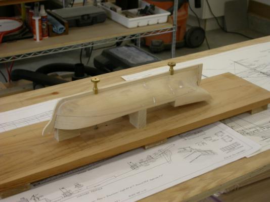
- 82 replies
-
- 11
-
-
Kurt, You could always scale up the drawings and scratch build her in 3/16" scale. I will be posting a plank on solid scratch build for the Topsail Schooner "Eagle" 1847 in the In Process Scratch Build Forum. Except for the built up bulwark, I used the same technique and assembly process as "Newsboy". Pete Jaquith Shipbuilder
-
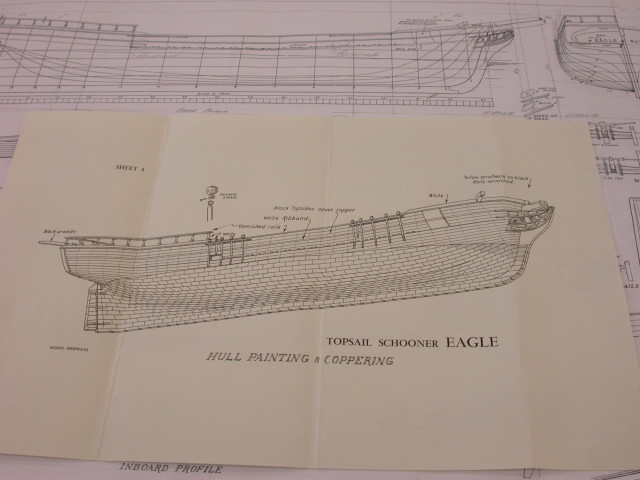
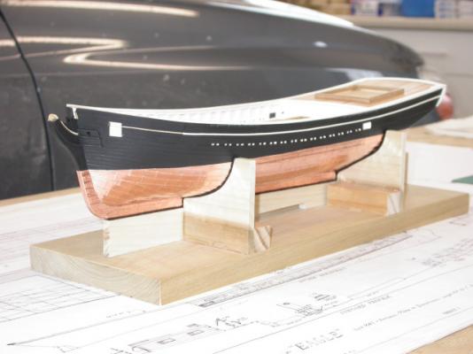
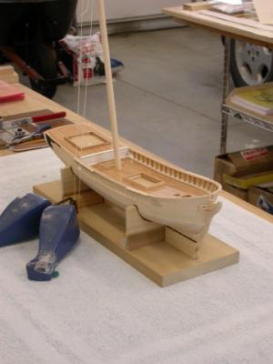
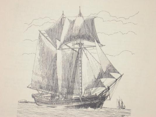
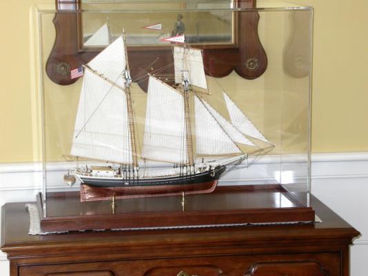
The Topsail Schooner “Eagle” had a length of 81’ 7”, beam of 22’ 8”, depth of 7’ 10”, and tonnage of 140 tons. Both the “Eagle” and her sistership “Arrowsic” were built in Arrowsic Island on the Kennebec River (near the present shipbuilding city of Bath, ME) in 1847 for the lumber and ice trade by builder Samuel Pattee. During the mid-19th century small schooners of this sort were widely employed in the East Coast trade; their schooner rigs an easy adaption to the prevailing westerly winds and economy in crew size. The model was scratch built to a scale of 3/16” to the foot (1:64) using old Model Shipways plans by William Zakambell. Additional research was conducted at the Maine Maritime Museum in Bath, ME where a large scale model of the “Arrowsic” is on display. The model is plank on solid construction, with built up bulwarks, planked decks and topsides, coppered bottom, and scratch built deck furniture/fittings. Limited commercial fittings were utilized where appropriate, and the rigging is proportional linen line with Warner Woods’ blocks. The Topsail Schooner “Eagle” is my 3rd wooden ship model and my 1st scratch build. Pete Jaquith Shipbuilder
- 82 replies
-
- 16
-
-
Thank you for your interest in "Newsboy" 1854, The above posts address my Brigantine "Newsboy" 1854 construction through February 2014. "Newsboy 1854 is now in storage until I complete my current 1:1 scale shipbuilding project in North Vancouver, BC Canada. "Newsboy" has been an interesting build and she is a beautiful ship model with clipper ship like lines. When I restart construction, key activities will include: >>> Assemble masts and complete mast rigging setup >>> Complete hull rigging setup >>> Set masts and complete standing rigging >>> Fit spars and complete running rigging >>> Fit rigging coils and final touchup >>> Build case and fit model for display As time permits, I will post pictures of my Maine Topsail "Eagle" 1847 and 14 Gun Brig "Fair American", circa 1780 builds. Pete Jaquith Shipbuilder
-
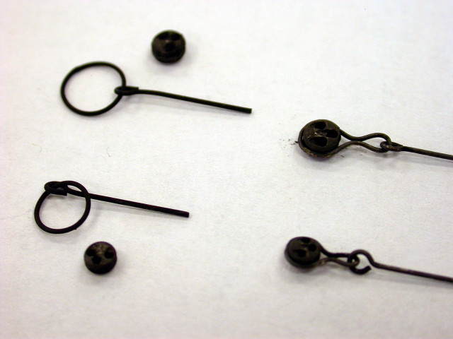
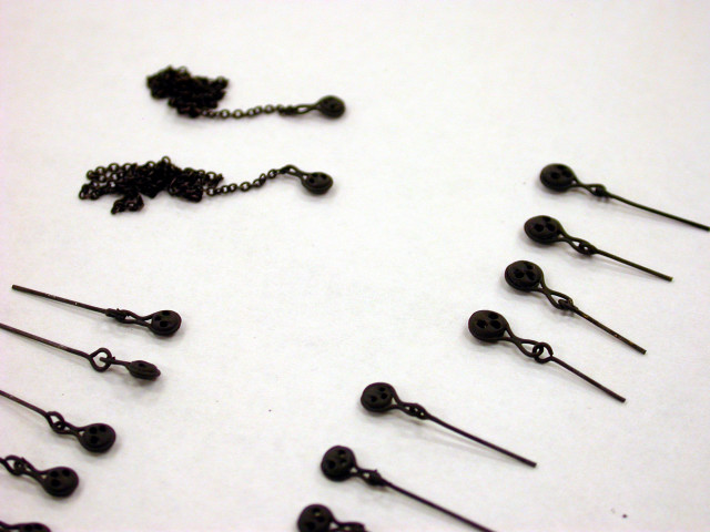
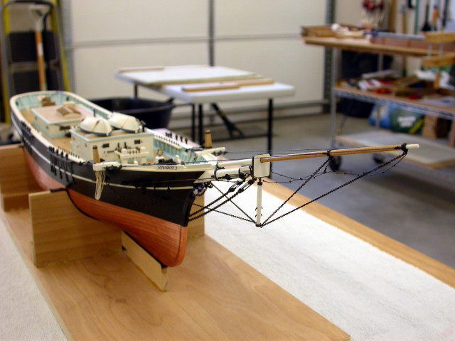
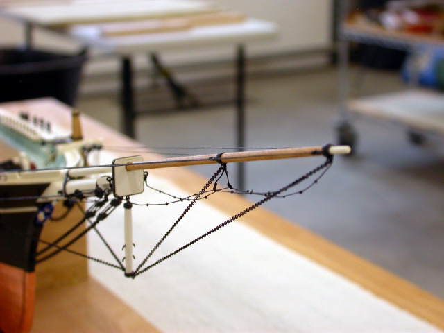
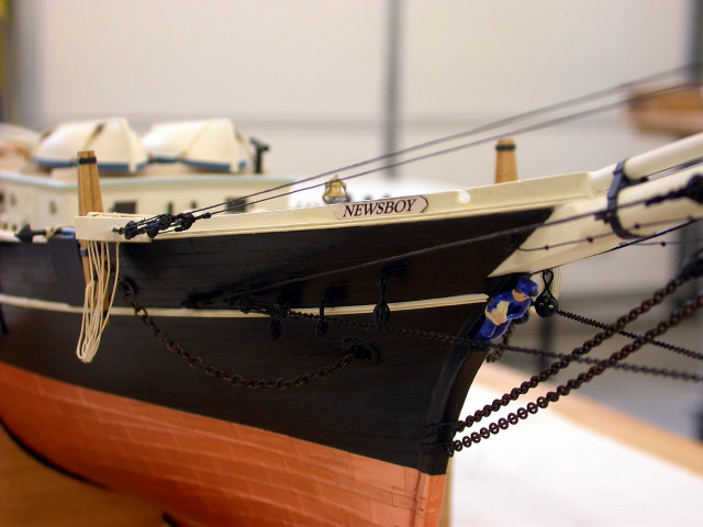
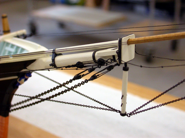
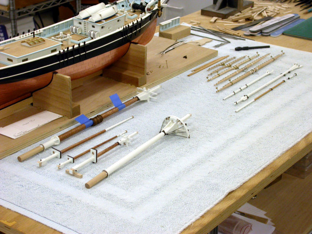
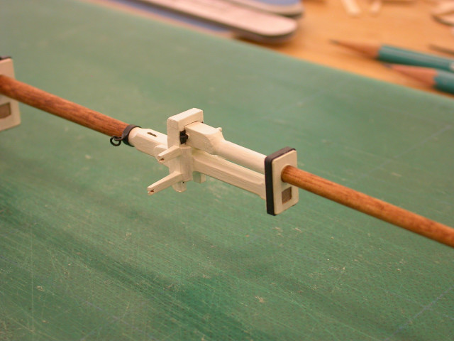
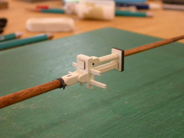
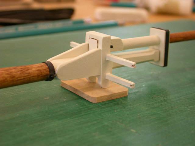
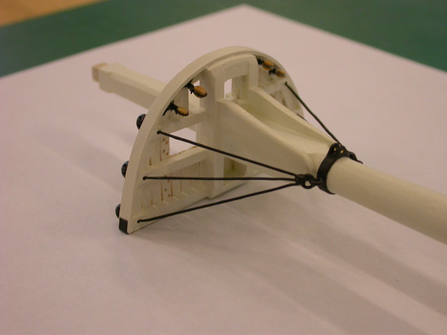
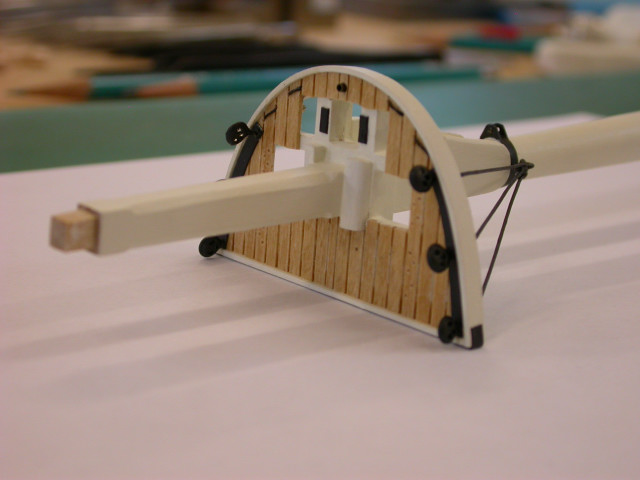
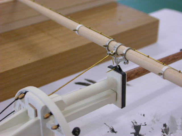
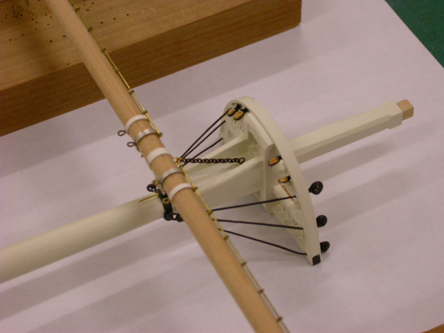
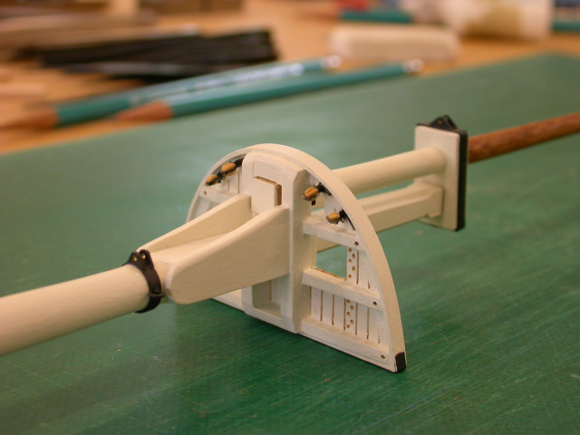
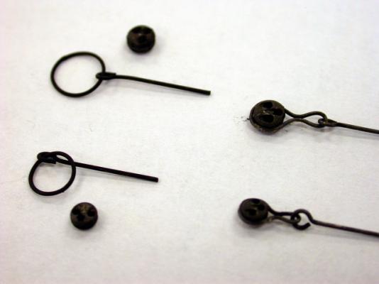
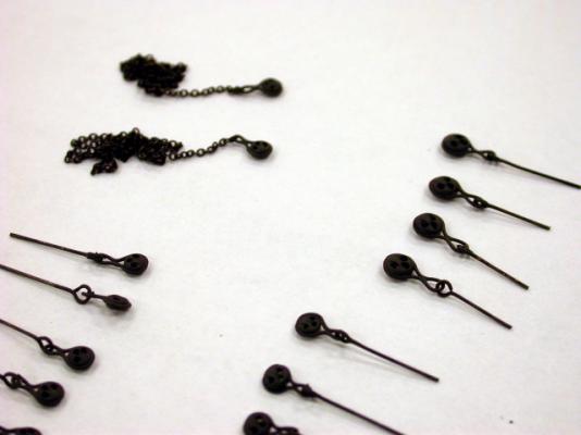
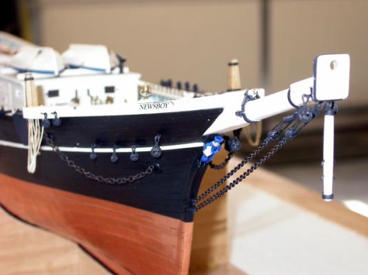
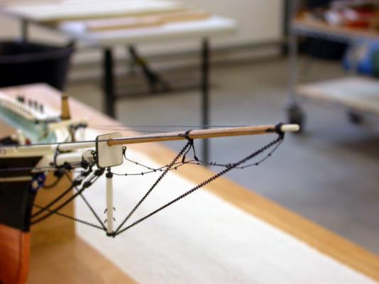
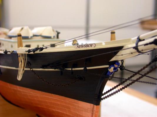
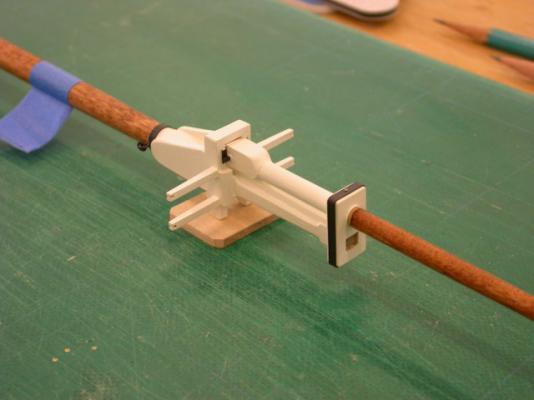
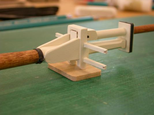
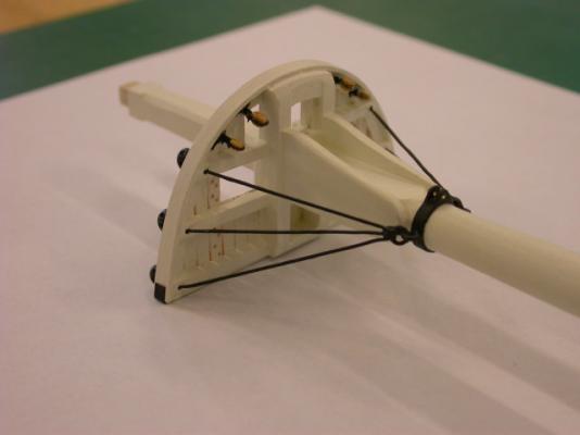
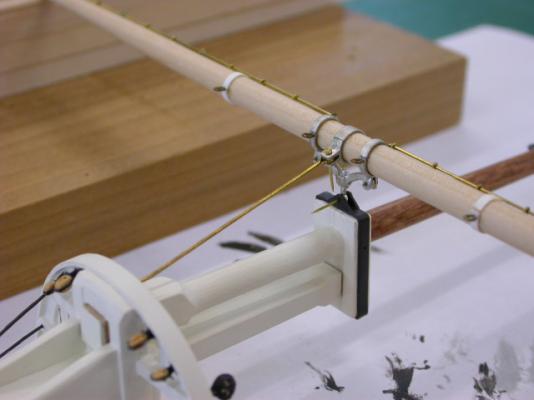
Thank you for your interest in "Newsboy" 1854, Next step is fitting the jibboom and associated head rigging. Key points include: >>> Deadeye assemblies prepared with silver soldered rings >>> Deadeye assemblies fitted to bow >>> Jibboom / dolphin striker outfitted with eyebands >>> Jibboom / dolphan striker fitted and head rigging installed >>> Martingale stays and backstays fabricated from 27 links/in brass chain >>> Balance of head rigging installation consists of tieing off the fore stays that pass down through the bowsprit bees and jibboom sheeves (following foremast installation) Pete Jaquith Shipbuilder


-
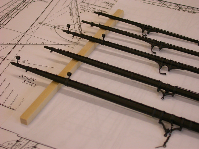
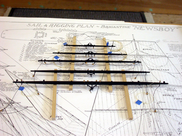
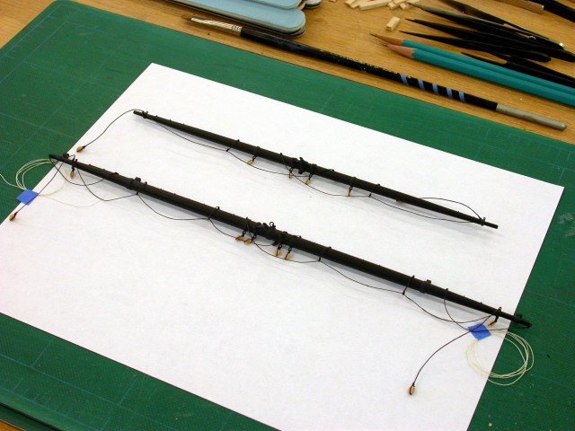
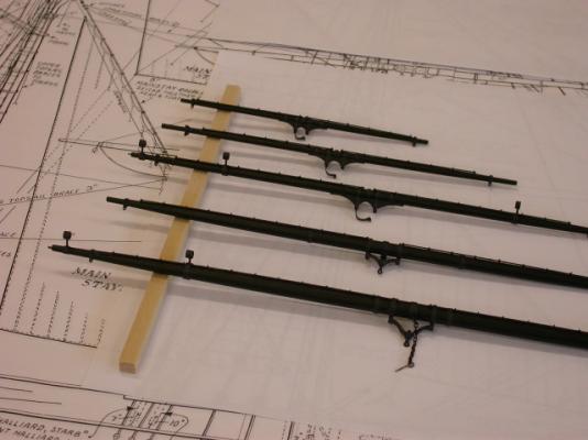
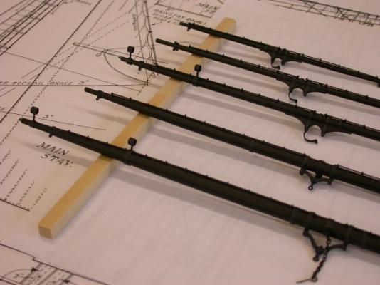
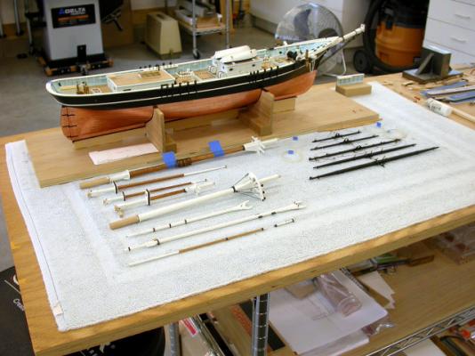
Thanks for your interest in "Newsboy" 1854, Next step is complete metal outfit, paint, and rigging setup of spars. Key points include: >>> Metal outfit, bands, sheeve holes, etc. per Rigging Setup Lists >>> Paint per Paint Schedule >>> Rigging blocks, rigging lines, and fittings per Rigging Set Up Lists Peter Jaquith Shipbuilder

-
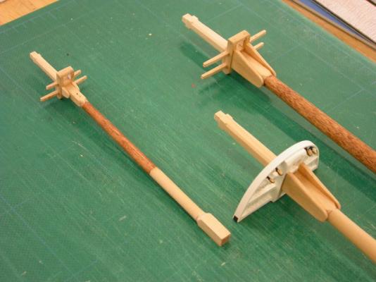
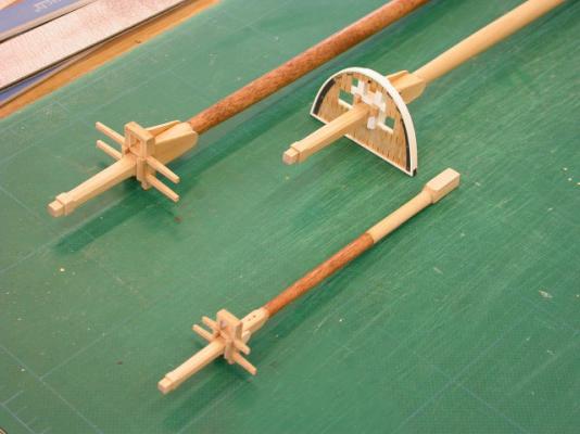
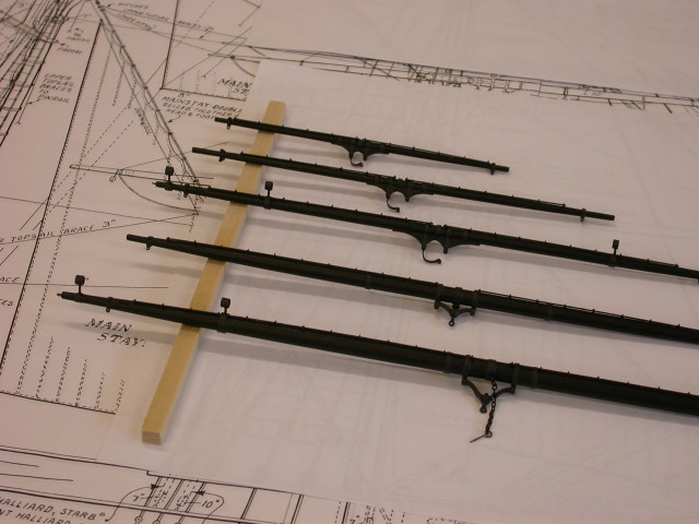
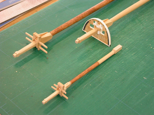
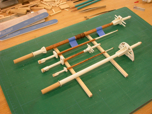
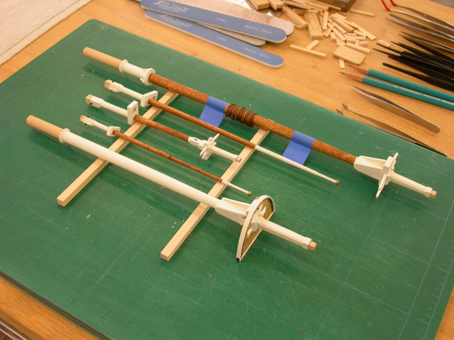
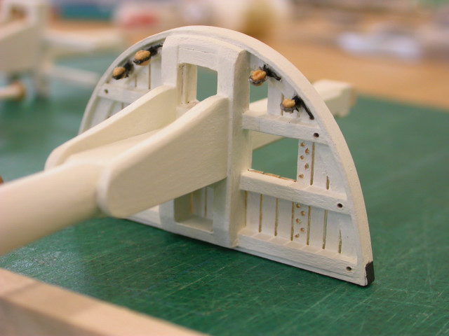
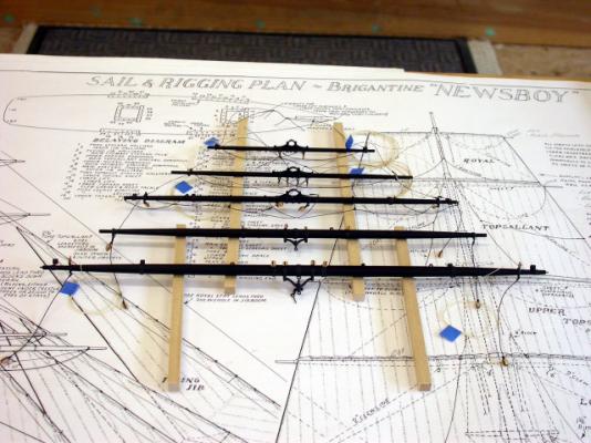
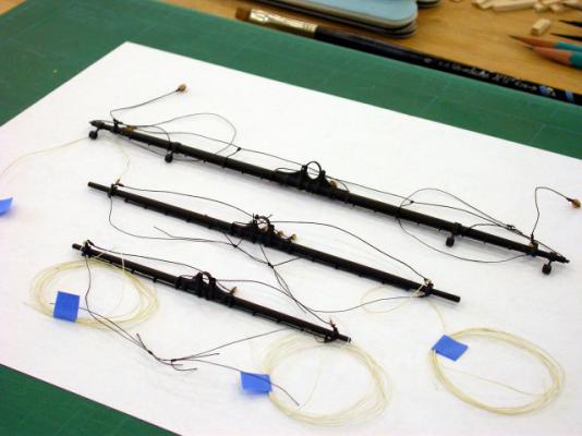
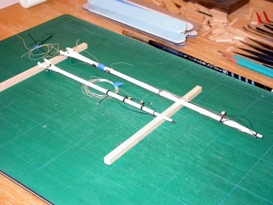
Thank you for your interest in "Newsboy" 1854, Additional mast assembly and outfit fittings. A list of special "Newsboy" rigging fittings typical of the mid 1800's is listed below: Spar Setup (1) Royal yard parrel assembly (special fabrication) (1) Topgallant yard parrel assembly (special fabrication) (1) Upper topsail yard parrel assembly (special fabrication) (2) Upper topsail yard studding boom quarter iron (special fabrication) (2) Upper topsail yard studding boom iron (special fabrication) (2) Lower yard studding boom quarter iron (special fabrication) (2) Lower yard studding boom iron (special fabrication) (1) Lower topsail yard clevis assembly (Britannia casting) (1) Lower topsail yard truss assembly (Britannia castings) (1) Lower yard truss assembly (Britannia castings) (1) Boom sheet assembly (special fabrication) Mast Setup (1) Main mast crane (special fabrication) (1) Fore mast cap clevis assembly (special assembly) (1) Fore mast clevis assembly (special fabrication) (1) Iron stay assembly (lower topsail yard stay) (special fabrication) This post completes mast fabrication and the fitting of mast ironwork. When construction resumes, mast sections will be assembled and outfitted with blocks and rigging lines per Rigging Setup Lists. Pete Jaquith Shipbuilder


-
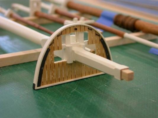
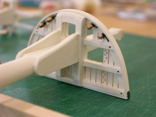
Thank you for your interest in "Newsboy" 1854, Next step is assembly of mast sections and fitting mast ironwork. Key points include: >>> Cross trees & fore top fitted >>> Upper masts dry fitted and caps installed >>> Mast / cap ironwork, bands, and clevis bands fitted >>> Special fittings fabricated (silver soldered) from brass strip, tube, and channel sections >>> Mast hoops fabricated from .020" x 1/16" basswood wrapped around larger dowel, cut to length, and glued Pete Jaquith Shipbuilder