


kruginmi
-
Posts
630 -
Joined
-
Last visited
Content Type
Profiles
Forums
Gallery
Events
Everything posted by kruginmi
-
 Druxey, the conundrum is that I need the above waterline version to reflect that seen at the museum. This will include the addition of gun on the centerline of the boat, which can be rotated port or starboard - though this feature will be removable. It is for their public excursions (pirates, for the kids/adults). They sail/motor 3 - 4 times a day 1-2 hours. The railing supports, but more specifically the step up found to the stern are all perpendicular to the waterline. It did push me to the enclosed POB version. Who knows, might create a second one that is more accurate, I will have all the data to do so. It is an interesting exercise. -Mark
 -
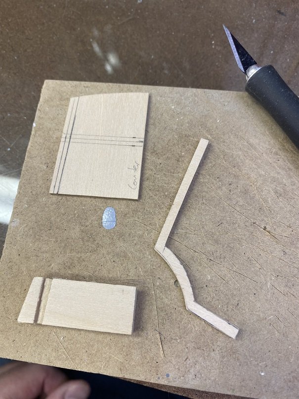
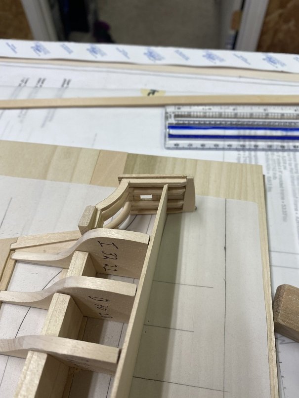
Pretty productive day - take them when I can get them. Focused on the stern aft of the wing transom. This is currently being setup as a bulkhead prototype but the intent is to also get the information for a POF set of plans. I worked with the prototype and generated the key transom set pieces (can't remember the name of these things). Trip down memory lane with the Druid. The problem here is that the wood is 1/8" thick (6" scale). This will snap in multiple pieces if you look at it wrong. So back to original construction techniques - laminate. I used 2 pieces of 1/16" thick wood and glued together rotated 90 degrees with respect to grain. Then there was a lot of measuring, cutting, sanding, frowning - repeat. Worked through all of the required things to consider (like the window and carving a slot into the transom for them to fit. I sit back and am happy with the progress today. Thanks for dropping by and taking a look. -Mark
-
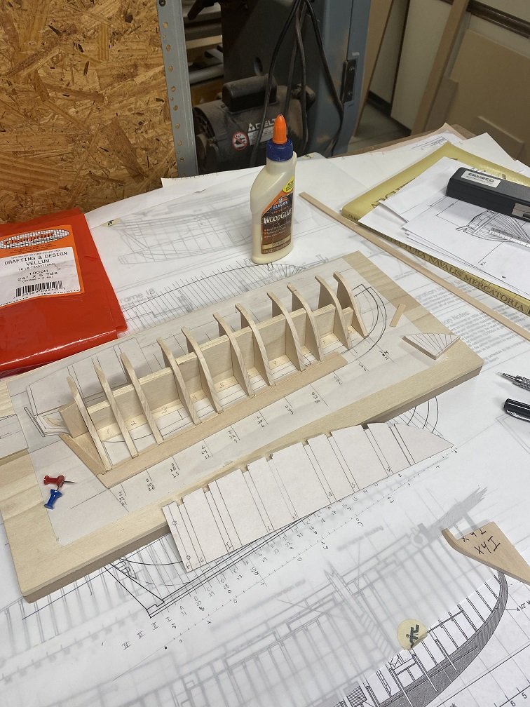
A host of clean up tasks to bring everything up to spec: - Redid first bulkhead. Somewhere this thing mutated. Now makes sense and looks right. - Lower false deck edges sanded flush with frames. - Upper bulkheads cut to allow for false deck - Upper false deck deck to shape - Rearmost bulkhead cut out Now actually looks like something. I did laugh at myself (you have to in ship modeling). When I removed all the paper templates from the frames there was some slop in the alignment slop (to be expected). I cut some wedges to firm things up. Half way through sanding I realized I had left the left side of the slot filler (ship to edge of board) tight but not affixed to allow for this correction. Remove all wedges and push in my adjuster. Job done. The Building Board is getting a little crazy (I glue on another bench). If I didn't know any better I look like I know what I am doing LOL. Thinking of adding another bulkhead forward. Since I am going to make a full POB this would be in line with this process. The rest will be a basswood block shaped. I want to get the stern buttoned up so that will continue. Then the Bow. All the masts, spars and such are all drawn out and correct (same as used on actual boat). The key is to get the frankenstein hull complete enough so I can make accurate plans that I trust. -Mark

-
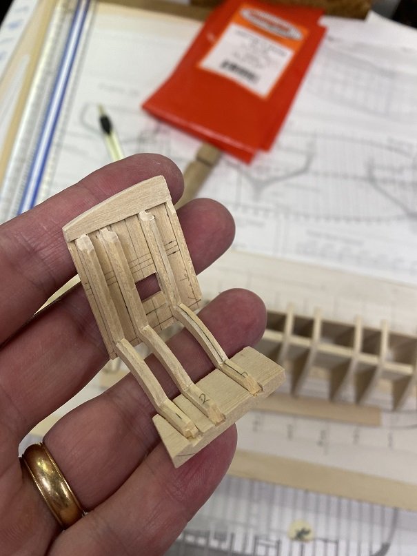
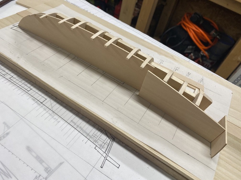
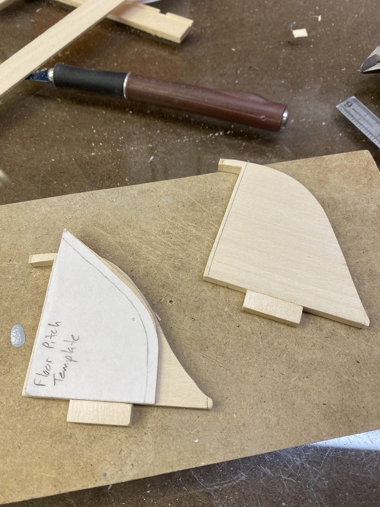
Decided to tackle the false deck next. This was not straightforward for a number of reasons but I thought the stability a false deck would bring would help so there you go. I did bevel the upper part of each bulkhead to allow a smooth transition fore and aft. Figuring out the false deck dimensions are not necessarily straight forward. Yes, there is an outline defined but the dimensions extend to the widest part of the ship at each frame, which may (or may) not be found at the deck level depending on the tumble home (but it is a start). So the first thing I did was take each bulkhead and scribe the deck level on the inner edge. I whipped up a Deck camber guide and drew in the deck extending to each bulkhead edge. Then, I drew in the rails that projected up to to hold the railing. Of course, doing some quality control checks showed the railing posts were too short and had to have small pieces added to achieve the necessary dimension. Here was my first dunder head moment: I had carefully measured, cut and sanded to the precise level just below the planks.....BUT did not include the space required for the false deck. MORE measuring, cutting and sanding (I had good tunes going so that was ok). I checked the resultant widths against the outline drawing. Above the false deck there was quite a bit of difference, below not too bad. I decided to cut out the deck as defined and sand any excess off later. Each bulkhead was measured against the deck to accurately place the railing post. This was cut out and verified. Finally the bulkheads were put back into their respective stations and all the pieces put on. (Seemingly the the first time) everything worked and I could look at this stage as being done. Still need to sand the little excess off of the false deck and actually put the bevels in below the false deck but calling this as milestone done. Now looking hard at the bow. That first bulkhead just doesn't look right. I need to re-verify and get that area so it makes sense. THEN sand the bulkheads to correct bevels. Stay Building My Friends. -Mark
-
I am posting today as a warning to others......Man, have I made stupid quality issues throughout! Attention to detail. This has almost become like work (ok, not really, and I am making progress). First up the stern. Remade the stern post to look more tidy and took a wack at a wing transom (or two or three wacks). The thing I keep forgetting is that the measurements can't solely be taken off of the as built plans, that the lower hull is from Chapman. Sigh. Finally got there in the end. Still need to cut the slots for the rear bulkhead supports (three per side). Still some tweaking to go there.. Bow: BIG ISSUE (okay, found out not so bad). I cut the template for the area between the foreward most bulkhead and the stern post (from the as built plans - the deck should be spot on so easy peasy). WRONG. The frame and template did not match up at all. I thought bad thoughts and swore the as built plans had issues. So frustrated I almost tore my plans in two. Deep breath. After cooling off and rationally looking at it I finally figured out I had mapped the frames wrong (ME). I had used frame W when I had labeled everything X. Luckily X was smaller in profile than W so with some quick measuring I cut the frame correctly and everything lined up. Phew. Bow: Another Issue. The drawn template laid down on the forward edge of the stem post (can't even remember the right lingo right now) as opposed to the bearding line. After more head scratching figured I had taken the as built deck dimensions (good job), but the as built layout did not include the protrusion of the stem past the planking. The as built ship is an unsinkable Coast Guard approved tub and really doesn't need or have this. So......I redrew the front of the ship to extend it out. Now the deck is the same as the as built (kudos) and I have the stem to seat my bowsprit on - Win Win. So lots of issues to work through but solutions found that didn't involve starting from scratch. Again, so glad I decided to do this 1/2 hull mock up to get through these things. Next up is to finish the rear bulkhead then cut out a false deck for strengthening the bulkheads but also to validate the deck perimeter and sand correctly. Wish me luck. -Mark
-
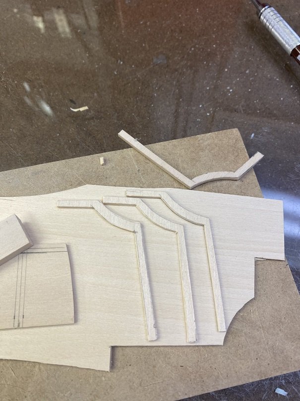
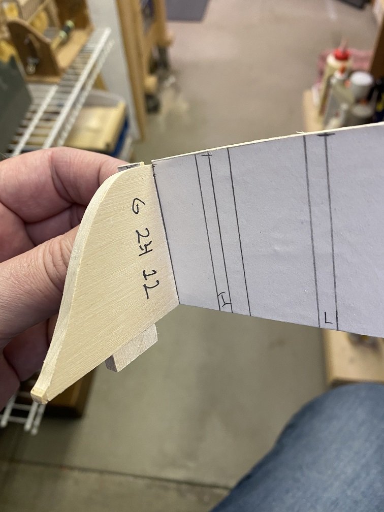
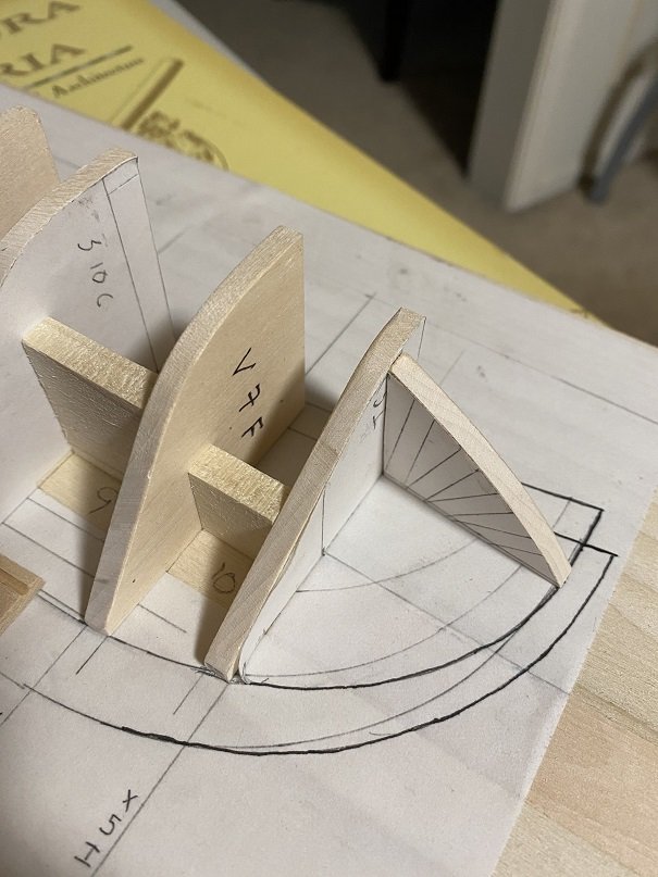
What a noob. I have been away from this hobby too long LOL. Thinking about what I had been doing (largely on automatic) and specifically the stern and realized a couple of facts: 1. I still need to cut the bearding line which would reset the planks into the keel but ALSO setup up for flush mount on the stern post (at least for the garboard strake). 2. The lines I had used from the Chapman I had forced to be the OUTSIDE of the planks. Duh. So the frames used on the stern were a plank width too wide on the bottom. Take the combination of the two and you have a much more organized stern that actually fits together. You have to laugh at yourself sometimes. The frames still have not been beveled so that will also help a lot. I do pat my back that this 1/2 hull is to prove out dimensions prior to investing in a bigger build so I take solace. The wing transom will be next to finalize this stern build area. Also the final stern post will have a dado into the keel. I also decided I didn't like the amount of keel above the frames, so I sliced down to an 1/8" total. Looks better. Pictured alongside is a 1/16" thick plank (3" scale), 1/4" wide (12" scale). Stay Building (and learning) my Friends, -Mark
-
On wards and upwards. The ends of the frames (near the keel) were a little hacked up. So, I cut a bit off and reconstructed to clean them up. I cut out a basic keel shape and also cut the frame slots out. The frames stick a 1/4" into the keel. An 1/8" of this will be a 1/8" slot for the frames to sit on and insure they are centered. Might cut the total slot to 3/16". The beauty of a 1:1 1/2 hull prototype. The bow is soon to come. Need to reacquaint myself on how to terminate the planks on the stern (below the waterline) for a Bermuda Sloop like design. No room to curve into the stem at all, has to have a bulkhead like piece to land on. Above the waterline need to also identify the wing transom and related architecture. Have to dig out my books. -Mark
-
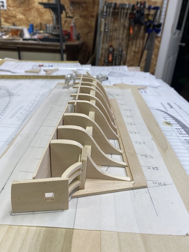
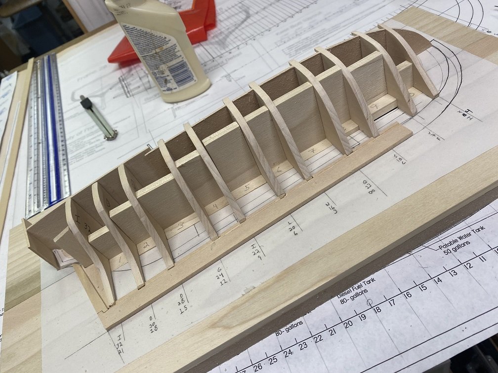
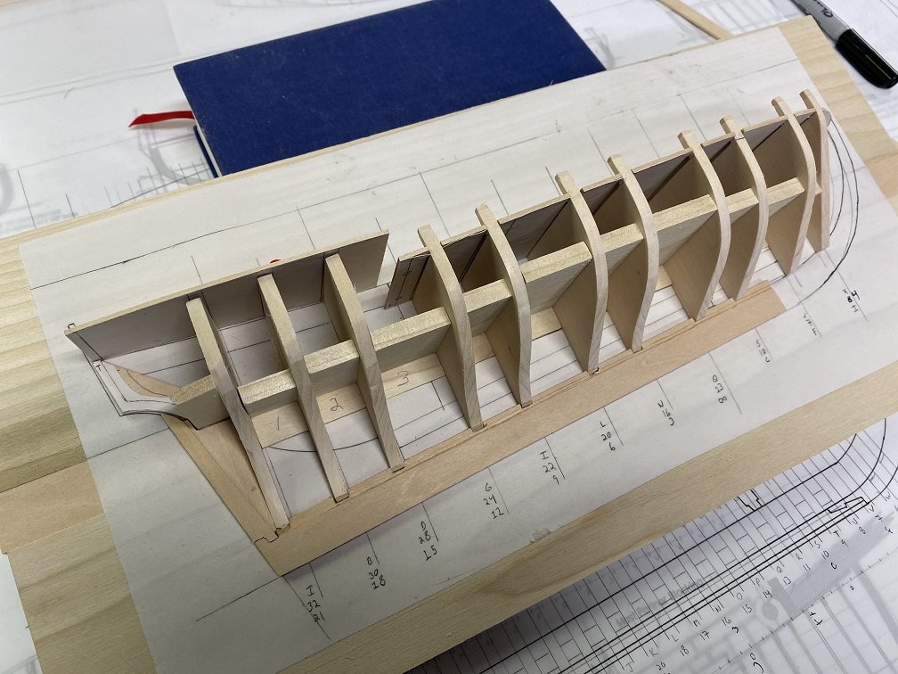
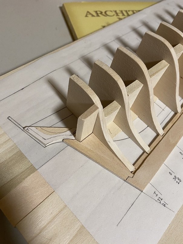
With a good fair wind I added the braces tonight. Everything still removable and all bulkheads lay flat to easily transfer to vellum when everything done. Next up is to clean up the bottom edges to the bearding line and work on getting the 1/2 keel added for strength. Also need to cutout a false deck to get that sizing correct. - Mark
-
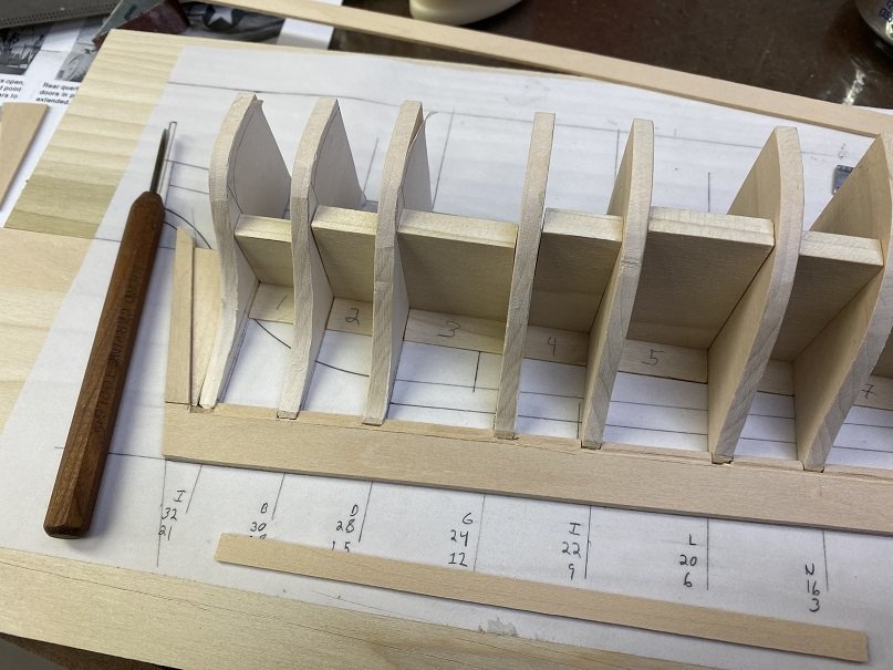
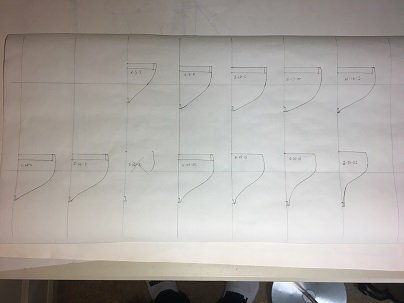
One note of caution (I think most understand this): When determining frame or bulkhead locations down the keel you cannot just measure from frame to next frame to next frame. Any measuring missteps will compound themselves over the entire length. With a 3/16ths inch width frame and 1/4 inch spacing these distances are not 'obvious.' So I have my handy dandy cheat sheet close by (partial shown below). All frames are identified with their respective size (3/16). I then (for ease of calculations) do a running total of how may 1/16ths inch each frame is from the stern starting point. This then is converted to the US method of measuring (metric would have been easier lol). So frame 'D' starts 1/16 of an inch smaller than 2 inches from the start line. The orange numbers denotes frames in the current half hull build. I include the dimensions of spacers to build between these frames (tonight's job). By using this any measuring issue is restricted to a single frame and not compounded across the whole. A lot more piece of mind. Stay Building My Friends, Mark
-
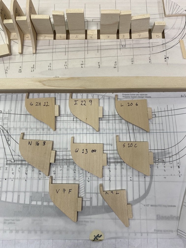
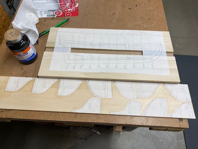
Hey, Progress! Visions of Druid dances in my head LOL. Long time since I have sniffed Rubber Cement. Got everything rough cut. Next up is to add the tabs for the backboard, then the spacers to solidify. A keel (1/2 width) also to be made to solidify it all and then......sanding. Always sanding. The three values shown per frame are the # frame I have drawn, frame from original FGW ship plans used to define top hull and finally the Chapman line used to derive bottom hull.
-
With all this down time (stay safe everyone), made some progress on the FGW. Got the 1/2 hull proto board setup and the confirmation frames drawn up and glued to a 3/16 basswood board (1/4" frame spacing). The notch for the board will be added later. Got to love the smell of rubber cement. I did a lot of off board quality checks on the drawn up frames (top 1/3 is equivalent to FGW, bottom 2/3 from Chapman plans). Given my hull depth and waterline adopted some issues arose which had to be corrected. Upon confirmation of these frames on the board, they will be used to create the master set of profiles. Currently thinking the initial build will be a full bulkhead one for speed of construction. I will see what the next week brings (did get a partial furlough from work so more time!). My other issue is I have recently taken up guitar. Competing hobbies LOL. Mark
-
Hey, Phantasm - sorry for delay. The Intellectual Property of the rigging diagrams is owned by the Michigan Maritime Museum. They currently have no plans to make them available (much to my chagrin and astonishment). I am hoping that this attitude will change. Mark
-
Hey Spellapeaka and Martin, Not dead yet! (haha). This thing called life has certainly flipped things upside down for me. I appreciate the comments and the nudge. The Lady Anne sits at arms length still ready for the rigging (laying in ordinary). Maybe it is time. Still love the hobby. Mark
- 128 replies
-
- 1
-

-
- artesania latina
- Finished
- (and 2 more)
-
This evening drafted my Frankenstein frames for a second time. It didn't take long and the first time drawing them refreshed my memory on a lot of things to think about and incorporate - not wasted time. Next goal is to get them affixed to 3/16" basswood and cut them out for the trial half hull. I got the wood for the baseboard so that will be done in concert. I believe they will be very close. That's it. Need to clean the area up and think about tomorrow. Cheers, Mark
-
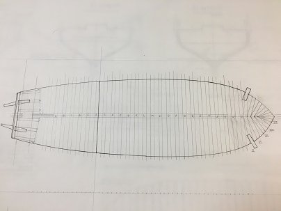
Alright, talking a bit with myself but trying to get myself 'centered' on a solution. I happened to pull out Hahn's plans for the Hannah (fishing schooner). Besides the fact that it has two masts, the hull length is consistent with the Friends Good Will (60 feetish). Looking at the profile pic it is evident that the the keel sinks ~4' over the length of the vessel given it that Bermuda Sloop look. When I look at the frame-up, it is also plain that the frames are perpendicular to the keel (and not the waterline). The visible bulkhead separating the main 3' higher aft deck is at an angle (as are all the frames) when resting on the water. I went back to Chapman and the Bermuda Sloop plan. The frame station lines as drawn are not perpendicular to the keel, but actually also are not totally perpendicular to the defined waterline (but are closer). They seem to split the difference. Things that make you go hmmm. It is why I love building from scratch HaHa. My currently drawn frame lines are done perpendicular to the water line. My thought is to continue in this vein. Again, it was a commercial vessel with no currently existing documentation so there is no specifically wrong selection among the choices. The boat in South Haven also has a bulkhead from main to aft deck that is perpendicular to the waterline so this will jive. I guess my decision is made. Perfect. Decision 32 done of 4,358 (estimated) total. BTW: Asked the spouse about this and she gave me a funny look. Cheers -Mark
-
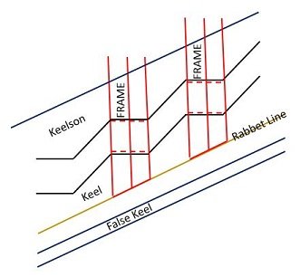
On thinking of it - this is a better graphic of my intention: The frames having insets into the keel
-
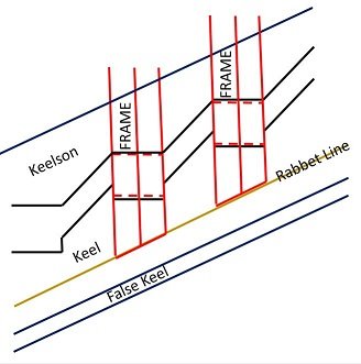
The Bermuda Sloop has a deadrise on the keel. Question for my esteemed colleagues: 1. My current thought is that the keel and keelson should be stepped for each frame. 2. The bottom of each frame would be angled to match the needed rabbet line 3. The 'assumption' is that each frame is perpendicular to the waterline. The following graphic (deadrise exaggerated for effect) illustrates my going in position: Any issues with this? An extension of this question would be the interior columns and bulkhead supports having the same effect on the topside of the keelson. Cheers -Mark
-
So, as I get back into the swing of things had a A-HA moment last night. My next step is now to make a half hull model using 1/2 bulkheads to the frames drawn, one that can be taken apart. The targeted problem to solve is to get the hull lines for the frames in between each defined Frankenstein frame (FGW above water line, Chapman below) corresponding to the Chapman station lines which this will do much easier and quicker. I can get close by drafting but actual physical ones would be great. I will add a 'key' block to each frame (waterline to 1/2" below) on each frame on the bulkhead centerline that will lock into a similar sized slot in the main board. The 1/4" spacers will be just that: 1/4" thick wood also keyed to fit into the same slot. Sounds more complicated than it is. This will allow me to finish sand all frame profiles prior to implementing as futtocks. I should finish up the final frame drafts today for the 11 Chapman frame stations - around 2-3 more frames will be required between each pair. Sounds more complicated than it is. When I get started and have pics it will be much clearer. Picked up the basswood yesterday so checked that box. I have thin OSB laying around which can act as the baseboard. Hope to start cutting in the next week or so. Good to be back. Stay Building My Friends, Mark
-
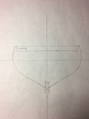
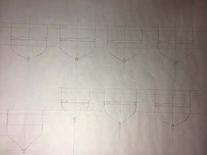
This post is describing how I am designing the 1812 period frames. I have opted for 3/16" frames with 1/4" frame spacing (9" frames, 12" spacing actual). This was built as a commercial vessel and no specific information remains on her so I am free to choose. The issue is the hull as built now is an unsinkable Molly Brown, built to Coast Guard specs for carrying passengers. If you squint hard you can sort of think of a Bermuda Sloop. My intent is to produce a model that is more period but still retains the known views on deck and above. 1. I first took the deck outline and laid down the frames and spacing as identified. My anchor point was the slight step rise between the main deck and the aft deck. I put this as a frame then went forward and aft from this. This resulted in 25 full frames identified. 2. Then I defined these frames onto the ship as built currently. This allowed me to identify the associated frames (thin laminates) that were associated to each of my frames. 3. I then drew the updated profile view spacing the 11 drawn Chapman frame slices at similar locations. I also added a three part identified for each frame: My frame #, the original plan equivalent, the Chapman frame line equivalent. 4. I scanned in the Chapman lines and duplicated them to allow full forward and aft frame lines. 5. On the actual frame views, I drew in a centerline and the newly defined waterline for my boat at that location. 6. On my drafting table I drew crosshairs to align the centerline and waterline of each frame. I put the existing frame drawing under the velum and copied only the lines above the waterline. 7. I then defined the bottom of the frame measuring from my profile view. I then slid in the Chapman Bermuda Sloop lines that I had scaled to as close as possible to the targeted size. I was happy to find a relatively close match at the waterline for intersecting. I traced in the resulting lines below the waterline to the keel. 8. When I pull away the Chapman lines I am left with a pretty good shell of the frame at that station. 9. I then added the building board location (Hahn style build), frame extensions, keel, etc. It didn't take too long to make 7 of the 11 targeted frames. My intent is to make bulkheads of these 11 frames using 3/16" basswood and use them to verify all is well. Eventually full frames using 3/32" wood will be created for the final framing. I believe this will result in a true Bermuda Sloop shaped hull of the period that will allow the deck as currently exists to be also created. I am open to suggestions for improvement but will hold the final say on implementation LOL. Cheers, Mark
-
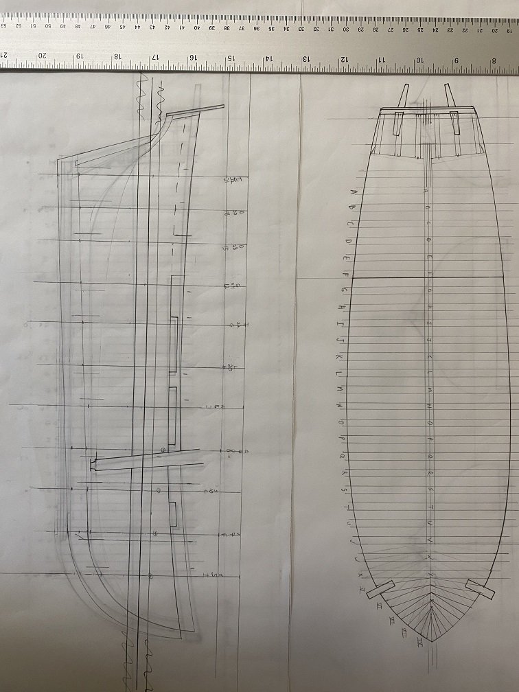
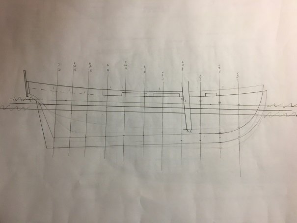
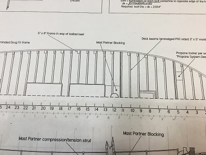
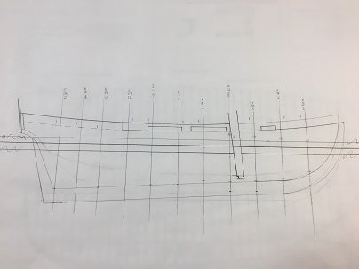
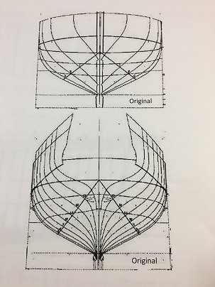
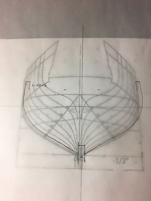
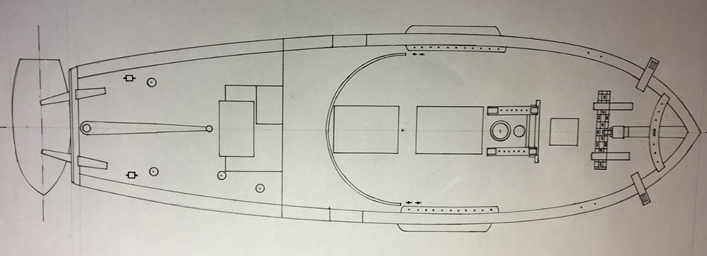
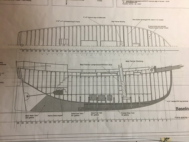
Good to be back. Rehashing some basics I have done previously, I focused on the deck and hull side profile: This is a drawn deck, but equivalent to the current ship (some mods from original plans). The arc in the middle is a track for a gun that sits center ship and is able to be pivoted to either side. Not historically accurate I believe (used on their pirate sail). One of the thinking points is how to handle such things. More on that later. The hull profile (as built) shows an unsinkable Molly Brown. It is triple laminated planked (second layer at 45 degrees) along with crumple zones etc. Forward keel is lead, aft keel is water tank. Not very 1812 construction LOL. After a lot of work, and deciding to base the hull on Frederik Chapman (Plate LVII, #15) the following hull profile was defined: This is a merging of the ship as built (primarily above water) with the Chapman layout (primarily below water). I had to adjust the water line to get a happy medium a couple of times but I am pretty happy with this Frankenstein mix. The distortions you see are from the camera angle used to take the pic. All drawn frame reference lines are perpendicular to the water line (reference lines directly align with Chapman reference lines provided). Stay Building My Friends - Mark

-
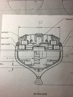
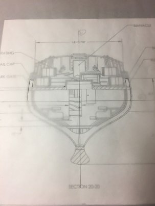
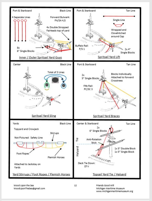
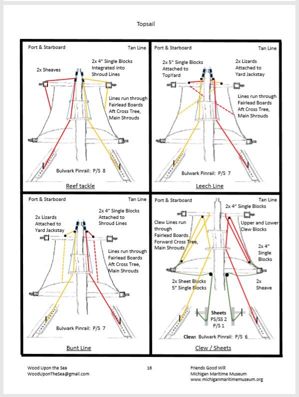
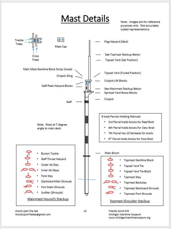
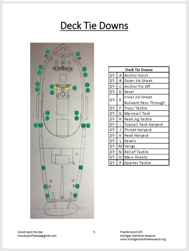
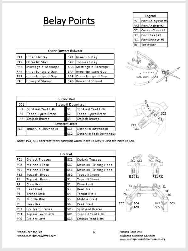
I spent a lot of time with the ship master going over every aspect of how the boat was rigged. It is unrigged every winter for maintenance. This gave me a lot of close up and personal time with each and every piece, being able to categorize every connection point and examine closely everything (except the mast). I produced a 27 page rigging booklet that the museum is VERY happy to have. I learned a lot, made friends and had fun. Attached find some excerpts from this endeavor (all my work):


-
Well, it has been awhile but the wood always waits. Good to see a lot of familiar names (and faces!). Summary: I am working to build a 1:48 scale model of the 'Friends Good Will' by access to replica build plans and lots of one on one discussions with the ship master. The Michigan Maritime Museum sails a recreation of the 'Friends Good Will' - a Bermuda Sloop that participated in the War of 1812 on the Great Lakes (both sides). My family went there one day and I was very interested in what I saw. Several inaccuracies were very apparent for the sake of safety and the ability to host guests (sails 3 times a day for 1 1/2 hours) but it felt great to see an actual wooden ship in action. At the gift shop I inquired about ship plans, hull lines, etc and was met with a blank stare. I finally was referred to the museum historian and asked about wanting to make a model of the ship. Apparently I was the first to ask such a thing so next thing I know I had full access to the build plans and unfettered access to the ship master. Things to make you go hmmmm: 1. The rigging in its short life has been drastically altered since delivery. There was no accurate documentation of the current rigging setup other than in the ship master's head. 2. The hull (especially underwater) only very crudely resembled a Bermuda Sloop. 3. How to represent the topside deck - as built or more like it would have been. The work before me was large, but I looked forward to the challenge. Join me on a journey from drafting model plans to construction (using the Harold Hahn method). -Mark

-
I just got this book for Father's Day from my son and I wanted to add my very favorable impressions from page 1 to page 197. Incredible, just simply incredible. I read half the book last night, finishing it up today. The pictures are numerous, spot on and just simply go on and on. As a builder of a plank on frame model I found this insight into an original 3 decker build very informative and will help me going forward. For example it is okay to simplify some structures (the one piece after cistern as an example), or have a non functioning tiller. It is okay to use 'SWOPEM' (Situation Where One Part Equals Many). Great to see was the presentation of 'Nobody's Perfect.' A pictorial of things found on the model that were obvious mistakes or modifications made to account for fit by the original builder was awesome. They happen to everyone and glad to see (once again) it is okay to keep them on the model. My only 'regret' (maybe too harsh) is that the middle deck memory board (picture taken form directly above) is only one page in size, whereas the rest are a full two pages in size. I would LOVE to have access to these pics in a digital format. SO much to take in and learn from. I expect to pick this book up many times. When things are going slow, when I need some inspiration or I am figuring out how to advance my build in a particular area. A wonderful resource, a wonderful read and a book that I will keep close at hand. I highly recommend, especially those that are either in a PoF build, or have one under their belt. So much information about the internals of a ship model. Mark
-
Rigging Instructions 1/96 Revell Constitution
kruginmi replied to kruginmi's topic in Masting, rigging and sails
I will add a pic of something this is a better thing added in the newer instructions - Belaying pin identification. The older instructions just have numbers shown on which pin to attach to. The new ones have the same, but a separate breakout that identifies by name what is what. There are two pin out diagrams for the upper works. The above shows one of each. There are a total of 219 attachment points identified between the two diagrams. -Mark.JPG.fd23ea6b7fa64d3496da73fb7e00eebd.JPG)
-
Rigging Instructions 1/96 Revell Constitution
kruginmi replied to kruginmi's topic in Masting, rigging and sails
I agree they are newer versions. Just interesting that they occupy really the same real estate (same size paper) but for some reason it was decided to modify how presented. I believe the instructions are adequate for the model as built. Giving a heads up to people getting this kit of the differences out there.
