HOLIDAY DONATION DRIVE - SUPPORT MSW - DO YOUR PART TO KEEP THIS GREAT FORUM GOING! (Only 75 donations so far out of 49,000 members - C'mon guys!)
×


popeye the sailor
-
Posts
16,007 -
Joined
-
Last visited
Content Type
Profiles
Forums
Gallery
Events
Everything posted by popeye the sailor
-
 this is quite a kit you have here KEVIN........and a real neat subject to boot very nice progress so far.......don't envy you with the PE though
 -
now that would be an interesting thought to check out. it's known that biplanes had their wings removed during shipment {or most of them}. we had the foldable wing planes.......does make one wonder resin gun bays......yup you picked a unique one. very nice job so far
-
Fokker D.VII by RGL - Eduard - 1/72 - PLASTIC
popeye the sailor replied to RGL's topic in Completed non-ship models
I saw a page of the decal diagrams on your U boat project I was going to ask, but I thought I'd check here Raben's Ravens......Jasta 18......I have the Revell 1:24 scale model. super job ! -
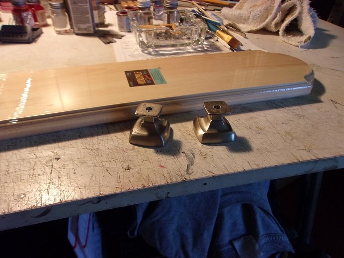
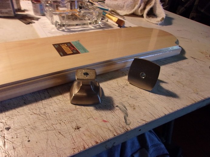
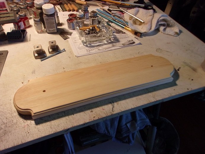
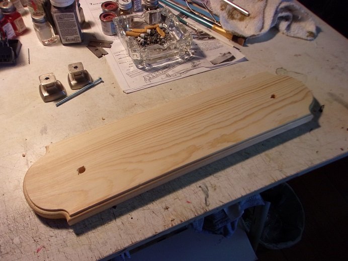
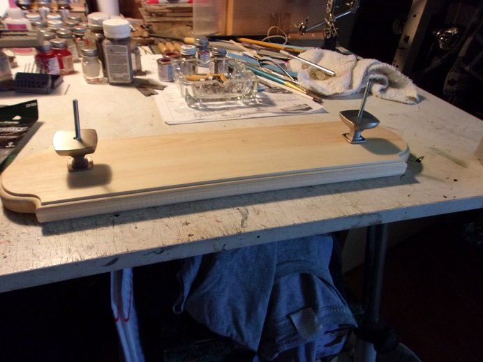
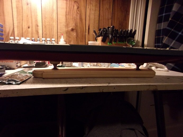
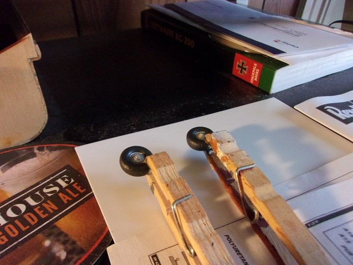
thought I'd put some movement on this log.......not huge, but a humble step foreword. earlier this summer, I went to Home depot and picked out a suitable pair of finials........a pair of draw pulls {knobs}. I was going to drill out the holes.......I need to drill all the way through them. distracted, I put them somewhere, and when I decided to do them, I couldn't find 'em! I looked in all the probable places I could have put them with no luck. I did another search recently with the same result.........can't blame the carpet monster for this one folks! so I went out and bought two more........these seem better suited. this is likely what prompted me to complete the task..........all in one fal swoop! I also bought the machine screws for them......#8.......and #10 X 3" with nuts.....two sizes in case I needed to go larger. I had to go slow with the drilling ......kinda tough to drill through. with the plastic still on the wood base, the center line was drawn, and the holes were marked out. the holes were drilled with the plastic still on the wood. the plastic was removed........the exit holes on the underside was chamfered to allow the screw heads to sink into the wood. I may need to change this up in case a washer is needed........I'll cross that bridge when I see how this goes. so, with the screws in place......as well as the finials, this is what it looks like the wood needs to be stained and sealed...........later. with the hardware removed, the base was placed on the hull and the holes were marked. these were drilled out. I found that 3" is a little too long..........but there is sufficient room in the hull, that they don't interfere { I can always cut them down too}. drum roll.................looks pretty darn good for a first time doing it usually, I use the stands that come with the model. this one is large enough to be an exception now I can stain it!
- 48 replies
-
- 10
-

-
- New Jersey
- Tamiya
- (and 1 more)
-
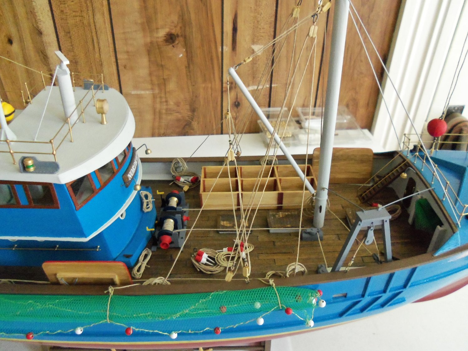
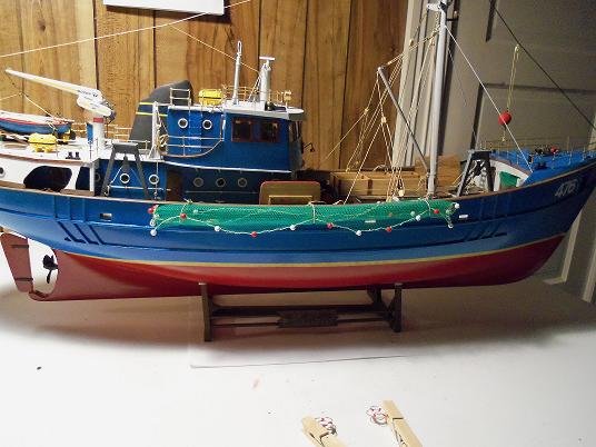
hello Sandy.....so sorry not to have seen your post sooner these boats are cool........I quite agree! as the log stated this comes from an older kit of the Billing Nordkap......older than the first Nordkap I built. I forget who built the boat that I'm emulating from.......I got them from a site called the Hull motor boat group. this site has closed down some time ago.......I was an active member. I haven't done any RC boats, but it was still cool to see what others across the pond were building the Progress was an actual kit that Billings produced, along with the Nordkap back in the day. being sort of a clone of the Nordkap kit, it's very easy to modify it. I have been thinking of this project lately...........I've been dabbling with plastic and I'm to the point where I'm beginning to scratch build things from plastic sheet. the itch may be returning I started to think over the bow cabin.........at one time, I was thinking of simply doing a foredeck instead. the idea has crossed my mind again and I'm beginning to like it more. I may also redo the anchor hawse holes........size looks an issue, but that's how they were also shown on the Nordkap. Robin's egg blue is what we call that color over here...........I have some too so.....at the moment, there has been no further progress on the Progress. I was getting ready to plank the deck........already made the margins as I did for the Nordkap. I hope to get back to her soon.......your inquiry may have lit a fire under my butt to get a move on...we'll see! here is a picture of my Nordkap, in case you haven't seen it alright........two of them. no one said I could count

-
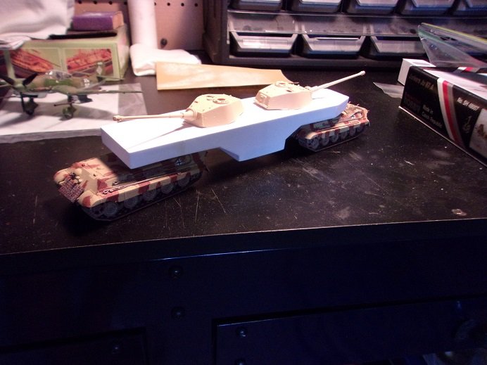
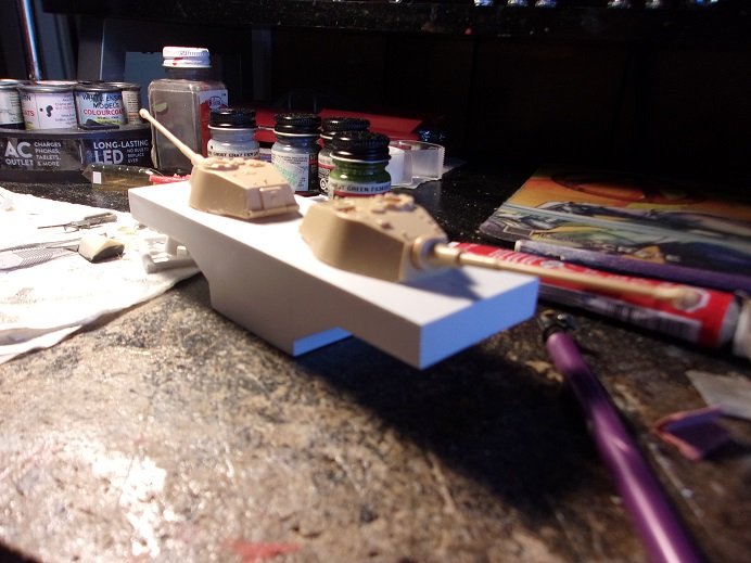
thanks gents.........it didn't want the turrets to go to waste.........or in a bin to be forgotten. I had the chassis already done, so it's a good way to make use of them. old model kits had anther Leopold kit in their listings, but I bit my tongue....too many expenditures this month. I also tinkered with scratch building a battle ship turret {the smaller ones}.......either that or a really good start on an AT walker trying to get back to this one........soon I hope!
-
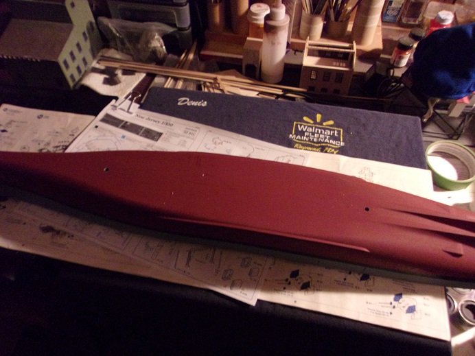
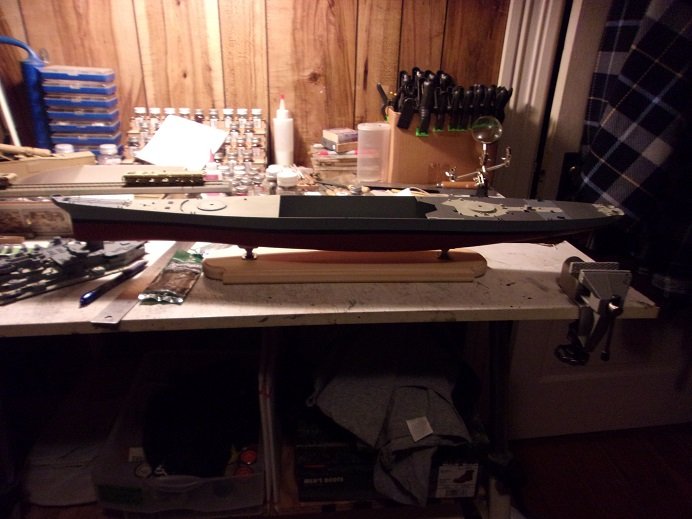
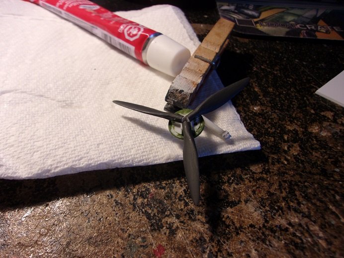
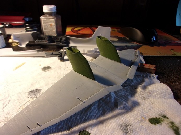
I was messing with the stand for the U.S.S. New Jersey today, and got the pictures from the camera. these are the prop........I mimicked the pitch from the revell kit prop and hand painted it. I tried to mask the yellow / green, but it was to much of a bother......and did it by eye. I also noticed that I need to do the yellow on the underside wing tips too.....more to come!
- 32 replies
-
- 12
-
-
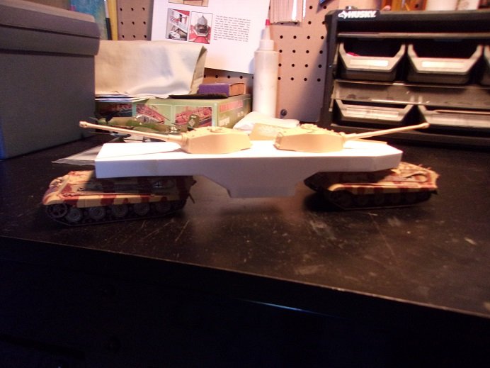
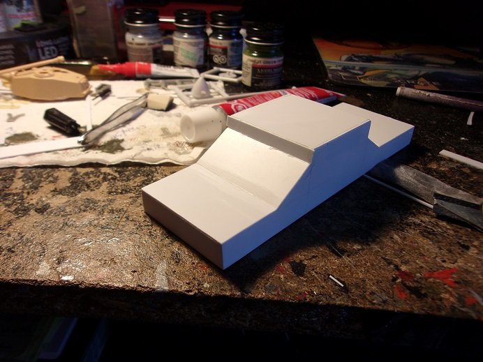
when the sanding dust cleared, it revealed a smooth looking gondola. it was dry fitted to see the results. hmmmmmmm......looks a bit odd. I wonder if the concept can be reversed? I found that it could without any problems..........the tapered end looks better in the front too it needs more to it........railings and such {i'll see what I have} I decanted the rust primer for the camo........more to come
- 104 replies
-
- 10
-
-
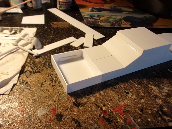
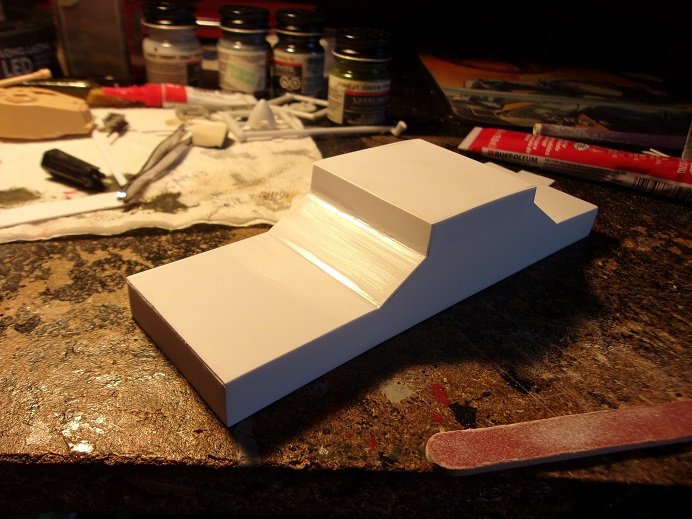
starting with what is to be the aft end, the parts for the add on was cut and assembled. I gave it a tapered look. with this end roughed out, work began on elongating the other end. this end was left as a flat end...squared. it then was closed up, and when dry, sanding and fill in gaps took place. lines were redrawn to remark the centers. when set onto the chassis, it looked more promising...the pintle and the hole could be set and drilled. all the while..........more sanding
-
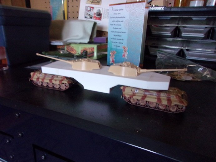
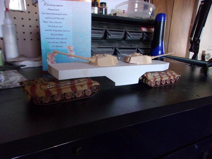
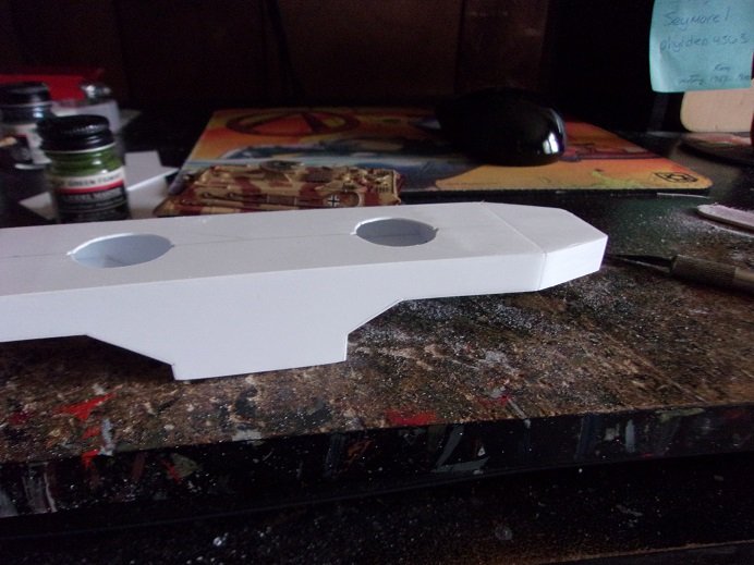
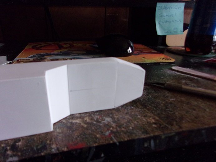
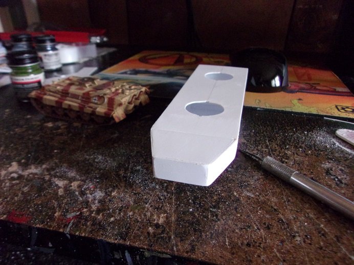
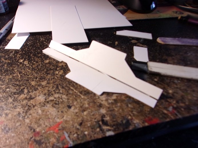
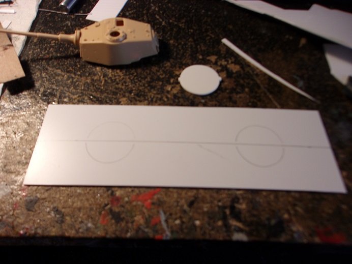
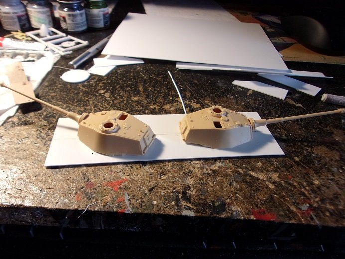
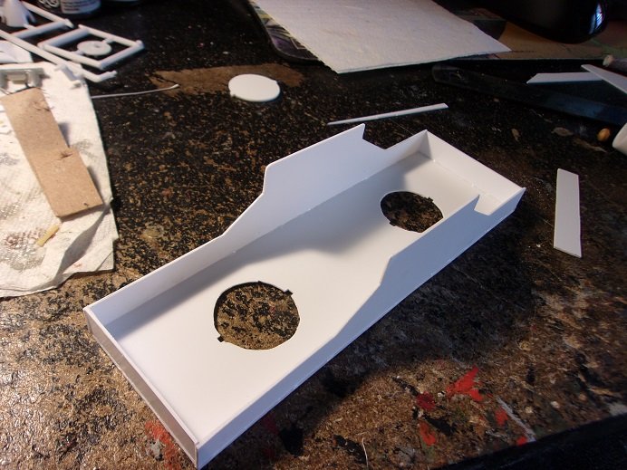
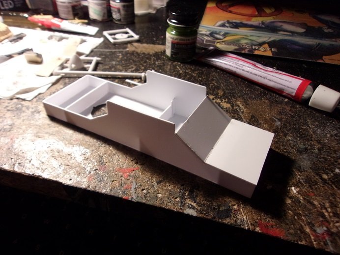
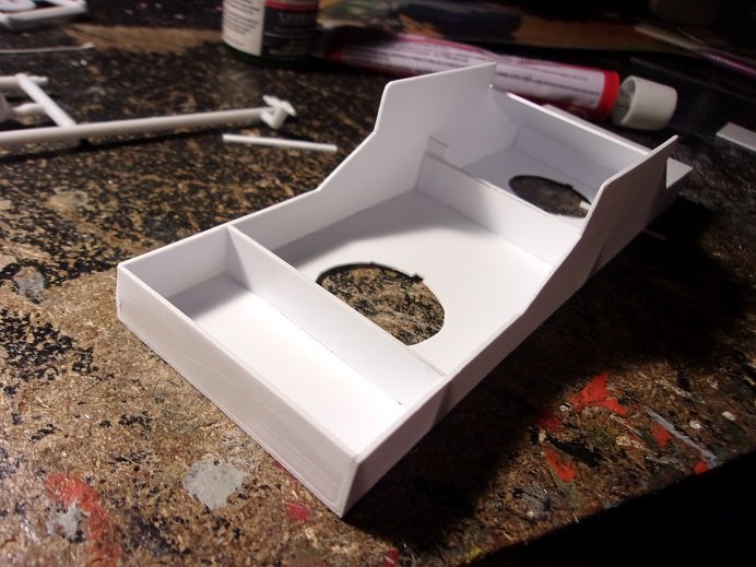
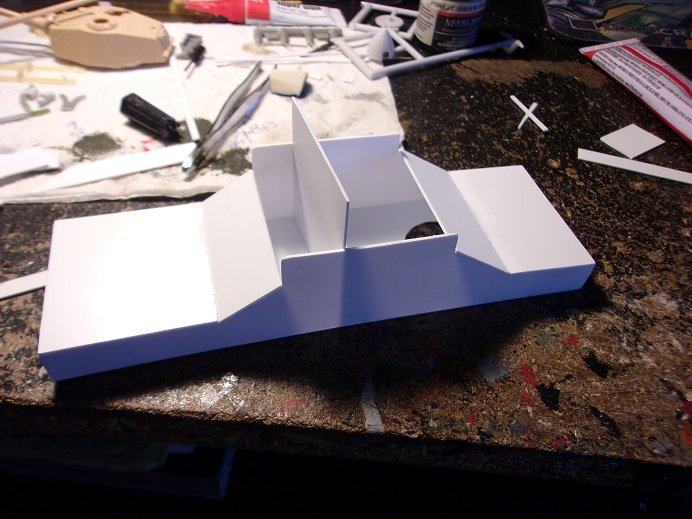
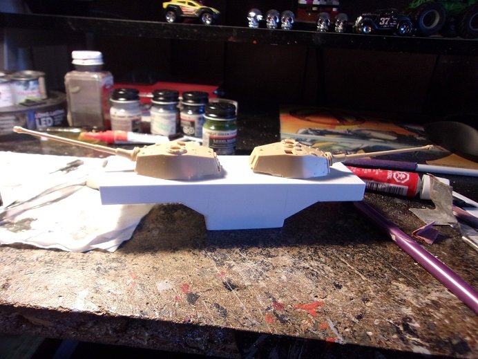
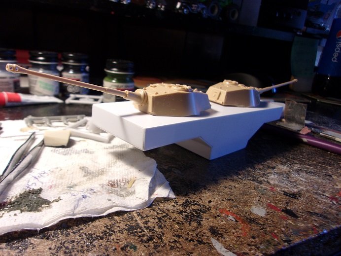
it's been a while..........I'm trying to revive and continue...please bear with me I did see a rail car like this in my searches.......so my 'what if' got the best of me. I knew the admiral won't allow me to get another Leopold kit to show both versions. so.......in my way of nonchalantly kick'in a can down the road, with enough sheet plastic on the desk, I set off tinkering. my early form of turret use wouldn't utilize both turrets, so I embarked on a small scratch build project that would. first would be to create a gondola that will host both turrets....the armored artillery vehicle begins. I'm glad I didn't toss out the cast off part for the turret plug....when I closed off the openings on the chassis. I used it to trace the openings on the deck. now to add the sides to the deck..... there was a lot of sanding to do. I didn't want the 'body' to be too thick on the coupler ends. braces were added to make the body stronger, while in the process of closing the body up. the sanding was constantly being done........I can't leave things looking rough for too long. filling in seams too....... the bottom area was closed up....seams sealed and of course, more sanding. fine sandpaper was used to smooth out the heavier sandpaper strokes. it should look quite smooth for when it's time for paint. the turrets were snapped back on to see how it looks. the next plan is to couple it up to the chassis.....from there will be the add ons and paint. it was disheartening to see that both cut aways weren't long enough to allow coupling.......I had miscalculated. pondering over the situation, it was decided to add on to the ends, rather than throw it out.
-
I have some progress to show on this project, although it's not much. spent more time tinkering than anything else........an addition to the Leopold project. added the gunner position and glass for it........and decaling. I managed to lose one of the fuselage pilot tubes....fell off and is lost....I may have to scratch build something to replace it. I painted the undersides of the ailerons to complete the yellow. I hope to have more to show soon
- 89 replies
-
- 10
-
-

-
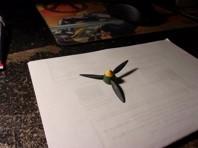
duly noted Mike..........please excuse my lag here. life has been busy of late.........life, work, and the satirical vehicle we own. just when I think I have the problem licked, it comes back. I just turned 66 the other day........the claim to fame of the day, was that I ate 3.4 LBS of steamers in 19 mins .......topped it off with a mega stein of beer and a seven piece shrimp cocktail! awesome day! during this stall in progress, only a little was made. I did a dry fit of what is done so far......... I have painted and assembled the prop and spinner......the pictures must still be in the camera. hope to have more on this project soon
-
old airfix kits.........closest I've come to them were the old MPC profile series kits look'in good Craig.....keep in mind though, some of the projects that don't look good in the beginning, sometimes look best when finished. it may be better to use the open version bomb bay doors, than the filler part.........it will look more realistic, and you won't feel like you need to scribe the door seams more to achieve the realism clear plastic parts can be terrible to work with. you could try buffing it to bring down the 'scratch' and then touch it up with window maker
-
nice start on the diorama Grant interesting use of chalk as a stain. are you going to use any sort of sealer afterwards?
-
thanks Ken......fitting the other radiator face. also experimenting with the cockpit glass.
-
look'in really good so far
-
very nice progress! the cockpit looks sweet! the admiral complained about play'in the lottery a few weeks ago, so I told her to play..........the darn ticket is still sitting on the fridge!
-
Cant Z.501 by RGL - 1/72 Suspended
popeye the sailor replied to RGL's topic in Non-ship/categorised builds
gives new meaning to 'strap in'! .....more permanent than the old fashioned 'jet lag' do you still have the kit Chris? -
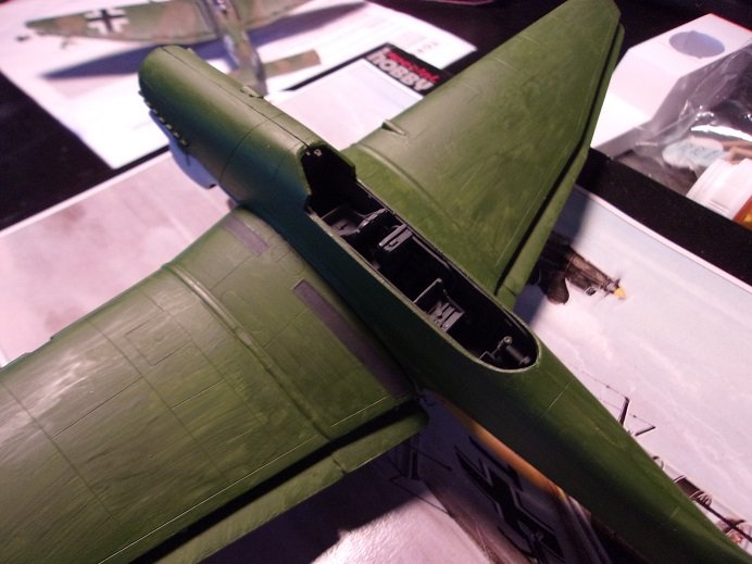
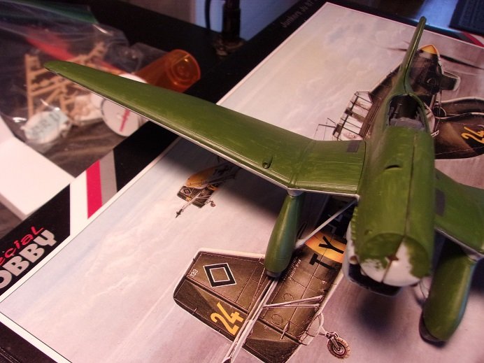
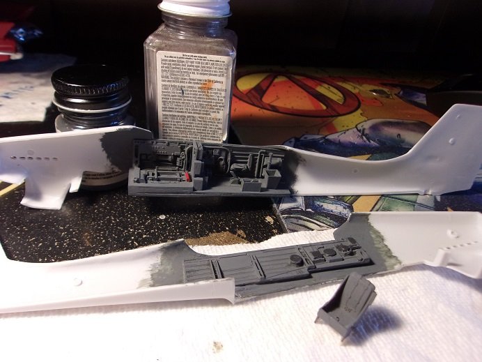
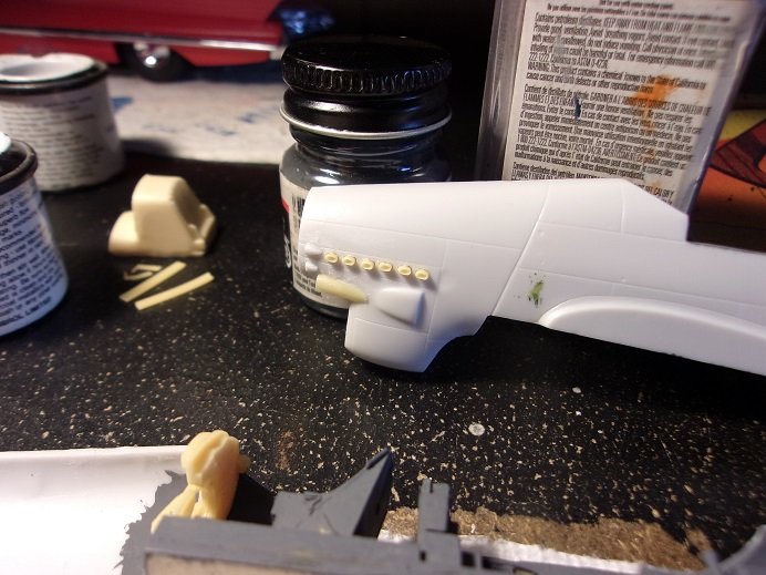
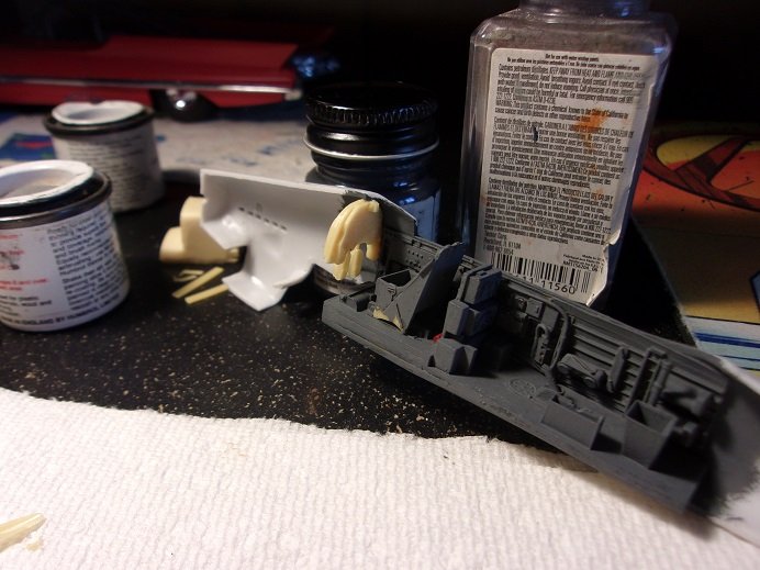
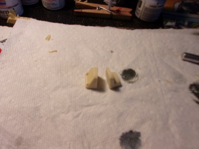
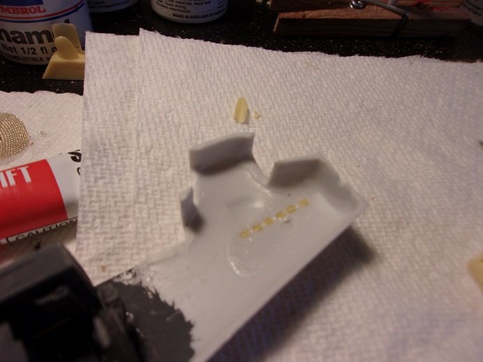
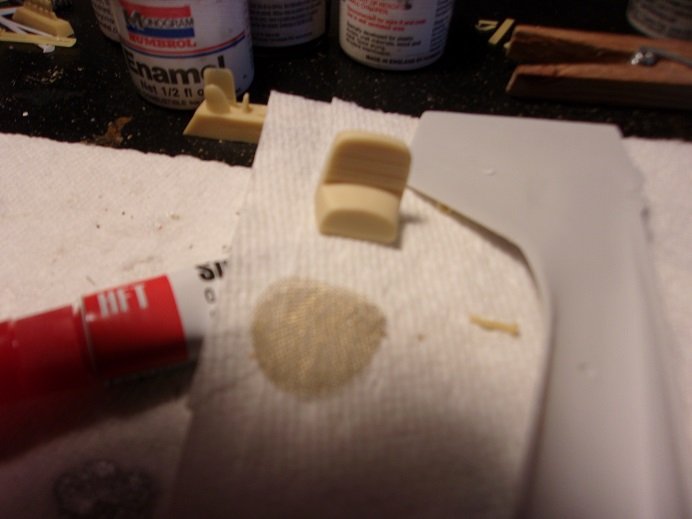
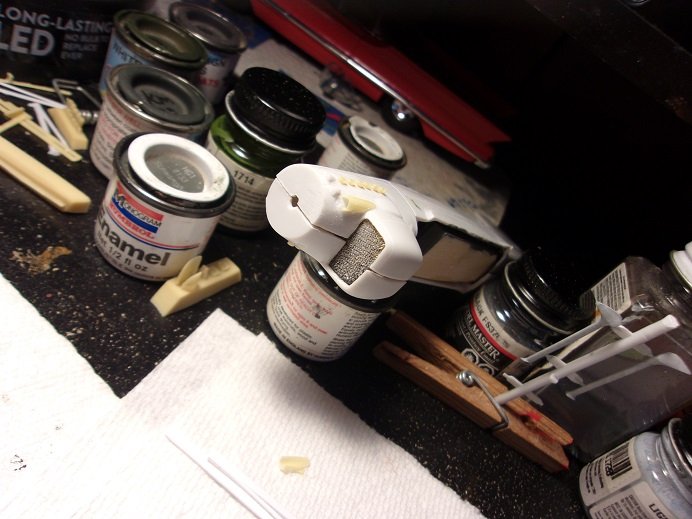
the next day, I repainted the cockpit interior....looks better gray. I added some of the added detail........there's more. the tires were also painted. I'm not finding any trouble using enamels. with the boots modified and painted, they were added to the underside of the wings. the exhaust are resin parts.......time to add them to the fuselage halves, along with other bits of detail. as can be seen, the instrument panel has been cemented in place. two pedals were added before this took place. it was sanded and trimmed down to fit. I also started to work on the radiators. together {the 'plug' as a whole} it did not fit the cavity......it sat back too far. I want to bring them more to the outer edges of the radiator box. taking the plug to the scroll saw, it was cut in half. the front radiator face looked kind of bland......it needs a grill like look to it. I recalled that I still had a couple of pipe screens. painted, it might do the trick. there was some cleaning out to do on the inside of the fuselage.......need to trim the part as well I did miscalculate and the result was a nasty gap. it took quite a bit more sanding and trimming to get me where I'm at....I still have the other plug to do. hopefully I can keep what I have. if I press it together, it becomes much less. still need to add the detail bits to the other half of the fuselage....still a work in progress more soon!
- 32 replies
-
- 10
-
-
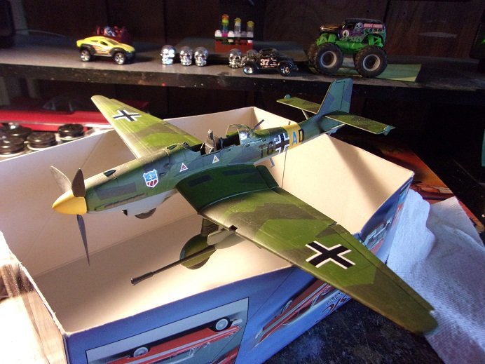
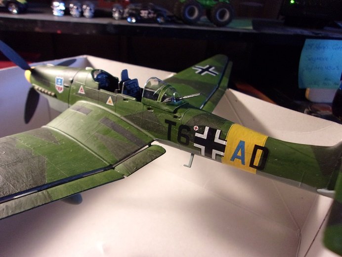
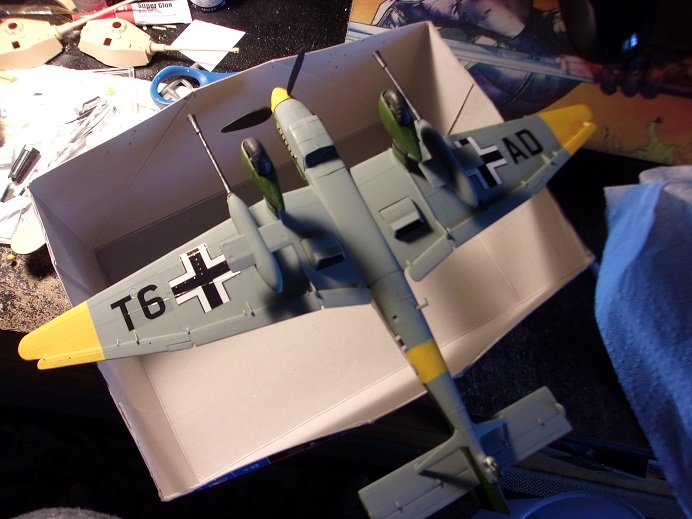
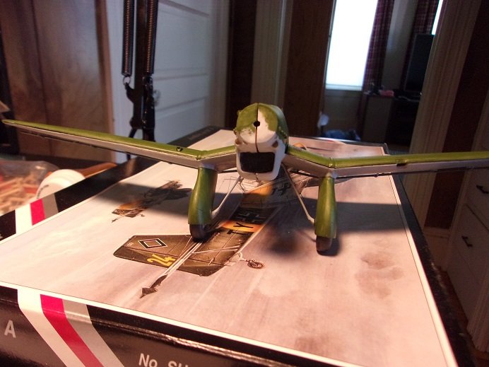
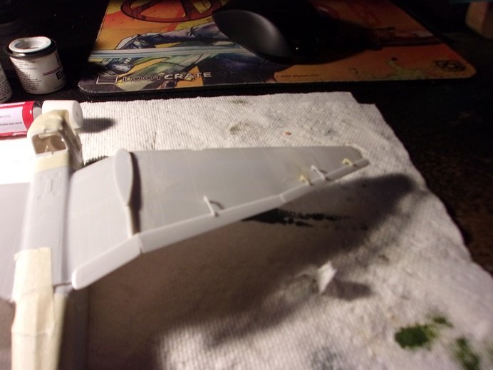
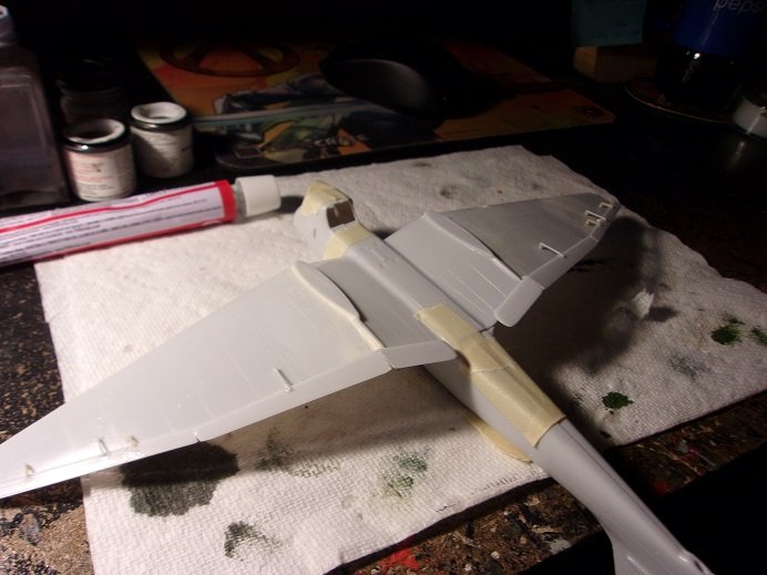
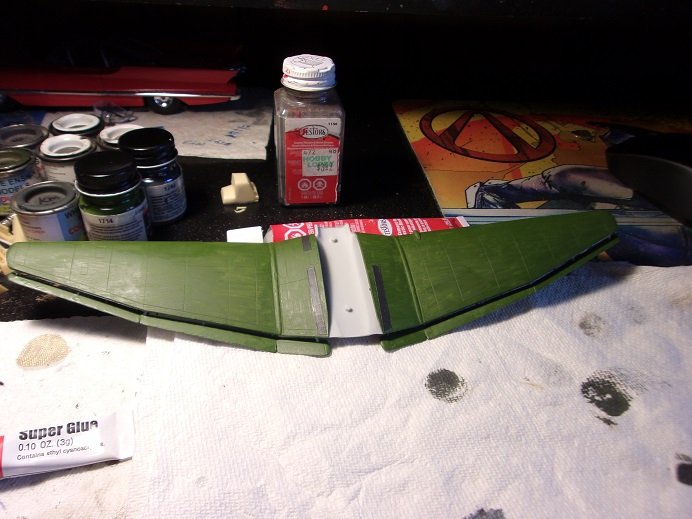
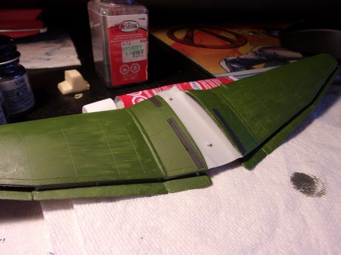
now.........barring any more interruptions......I can proceed! first off.....I got a good scare. taking Jav's advice, I put the canopy {the good one} in a window that gets quite a bit of sun. bad thing is......I forgot about it. we had a wedding to go to today, so I took a half day off to go {wished I didn't}. got home........made supper on the grill.......watched some boob tube..........and after enduring shows with little intelligence, I decided to finally post the updates. this is when I realized what I had done with the canopy..........whenever it was suggested was when I put it in the window! rushing to the window, I was startled to find that it had disappeared! I ran to get a flash light, since the only light in the room is set up for the fan at the moment. thankfully, the wind blew it out of the window, because I found it behind the speaker by the TV stand so.......yellow or not, it's getting painted and used! OK......at last post, I had added the ailerons to the wings.........I added all of the actuator rods. one set was resin, and none of them broke! once dry, the underside was painted a light Ghost gray the top halves of the wings were cemented in place at this time. they had already been painted........I stuck with the Forest Green as I did with the JU87G 1 the walkways have also been painted. the camo is the same as the JU87G 1.........I want to do something different. this will be the base colors. there is another update....more that I did on the next day. another bit of news that I got today. I came home around noon today...the admiral was play'in with her phone at the table. on the table was a model kit...........odd???? I ignored it for the moment and caught up on what she had done in the morning.......she wanted to go out with our younger son to Walmart, and buy another dress for the wedding. then I asked about the model.........she told me she got it from Walmart in the whole time I've worked for them {18 years Sept 20th}, I have never seen a model kit in their stores! ..........maybe somewhere else, but not 'round these parts! it's an old AMT {Round 2 production} of a '57 chevy Bel Air Hardtop....I asked her why this particular model.......and she replied because she liked it {she who think I have too many models} I have come to the conclusion, that she is an enabler

-
oh heck no Dan........these logs are designed to gather information. if anyone decides to build this particular plane, all he need do is look up this log, and he would have more info that he ever needed! not to mention the insane ideas to finish a great looking model. it's all around good stuff! I do have an update to report, but I'm told that we need to get on with the errands. so....I guess I'll just bite the bullet and get them over with. I'll see you all when I get back
-
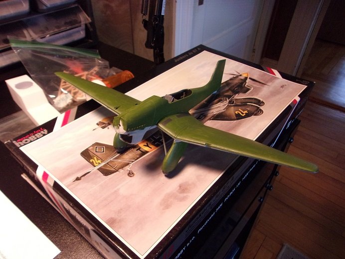
I'm doing alright......I have my days........still get the tired legs and the usual aches and pains, but that nasty sore is gone on my heel. it doesn't stop me though........ I forgot to congrat you Egilman.........glad to hear that your diagnosis is tipping in your favor I hope more goes your way! the JU 87A is more labor intensive than I thought..........I have only finishing touches to do to the JU 87G 1. the canopy is a pain.......the frame detail is nothing but raised lines, and I'm making a dog's ear out of it. I'm just going to even it out and be done with it. next one I do, I think I will go by way of the mask!
-
yep......decals can be a problem. either they are too glossy or flat, or they are thick or thin........thin making them more prone to cracking. you could paint the yellow and then source out black pinstripe decaling to finish it off. you can also print black stripe decal on your computer. I have a decal program as well. there are thing at your disposal that you can do. super silver job overall.........I think you succeeded quite well!