


Elia
-
Posts
539 -
Joined
-
Last visited
Reputation Activity
-

 Elia reacted to LMDAVE in Endeavour by LMDAVE - FINISHED - Amati - 1:80 - J-Class Yacht
Thanks guys, I want to get some better pictures in better light to show the colors better.
The clearcoat used was Polycrylic, a water based polyurethane, in the hopes that it wouldn't yellow the white lines, and it's held up so far. But, I probably should have let the basecoat blue cure fully before going over it, and by fully cure, I mean like 3 days to a week, I waited a day and a half, and a few of the spots cracked a little when the poly was dry, but I was able to sand it out inbetween poly coats.
-
 Elia got a reaction from Gerald Spargo in Charles W Morgan by Gerald Spargo - Model Shipways
Hey Gerald,
I'm very glad to see you back at Model Ship World, and very happy that you're continuing this super fine build.
Cheers,
Elia
-
Elia reacted to EdT in Young America 1853 by EdT - FINISHED - extreme clipper
Young America - extreme clipper 1853
Part 70 – Waterways
In the last post I mentioned the bolt density on the outside of the frames. This can be seen in the first picture.
The nails are part of the clamps being used to secure a section of waterway inside for gluing. The pins are markers for some of the through bolt holes drilled for this section. There will be more – one in each frame pair. The lower deck hanging knee bolts have not yet been installed. These will be dummy bolts only and dummy bolts will only be installed where the frames will be left exposed – lower hull on this side. It was not practical to drill for through knee bolts. All of the bolts for the ironwork lattice have been installed on this side plus of course many others for the members installed earlier.
The next picture shows the aft starboard section of waterway being fitted.
The outboard face has to be beveled to fit against the frames. The next picture shows a copper wire bolt for this piece being clipped on the outside.
I had a bit of rework to do on the main deck clamps aft of midship. For some reason – perhaps I neglected to plumb the hull before marking some of them – their fairness was off on both sides. I saw this on one of those deck-level camera shots. Since they were bolted on, removing them was a chore, but the new clamps are much better.
In this picture a batten has been clamped to the side under the deck clamp to help keep the sections aligned at the scarph joints where it is easy to get a kink in the line.
Although the main deck does not extend aft of frame 36, I decided to extend the deck clamps right through the cabin, joining it to a half-hook at the stern. The half-hook on the starboard side is shown in the next picture.
This hook is interrupted by the sternpost. Its wide breadth is dictated by the bevel required to fit on to the frames. There will be a deck full-width hook for the cabin deck about 4 feet below this – just at the top of the inner post. The cabin deck is a sort of mezzanine between the middle deck and the main deck.
The last picture shows the first section of 12” x 10” standing strake installed atop the he forward waterway.
The second section is clamped and glued in this picture. This strake has vertical hook scarphs.
Ed
-
Elia reacted to EdT in Young America 1853 by EdT - FINISHED - extreme clipper
Well, lets put it this way, David. Its not going to come apart.
Ed
-
Elia reacted to EdT in Young America 1853 by EdT - FINISHED - extreme clipper
Young America - extreme clipper 1853
Part 68 – Lower deck framing continued
In the first picture the beams around the opening for the main mast have been installed.
The forward beams and half-beams around this opening have double pillars – one on each side - set on the base timbers on the hold planking.
Making and setting these pillars, with their four knees each, is a large portion of the work involved with these beams. The next picture shows a monofilament bolt being installed in an upper knee that has already been glued into an assembly.
The next picture shows the three parts of a pillar assembly ready for installation.
The lower knees will be installed after the top assembly is set in place and glued. In the next picture the final beam – a half beam – is ready to be installed.
Unlike the other pillars, this one has been pre-installed since there will be insufficient space to do it later. The hanging knee has also been pre-attached to the half beam for this reason. The pillar is pinned to the base with a piece of wire.
The next picture shows the final beams installed.
Copper wire bolts have been installed through the tops of the beams to help secure the them, their hanging knees and each of the pillars these are glued with epoxy that has not yet been sanded off the tops of the beams.
The next picture is another view of this area.
All of the work below the beams has been finished with beeswax solution before installing the ledges. Missing lodging knees, carlings, ledges and a lot of monofilament bolts still need to be installed to complete the lower deck framing.
The last picture shows most of the lower deck at this stage.
Ed
-
Elia reacted to EdT in Young America 1853 by EdT - FINISHED - extreme clipper
Young America - extreme clipper 1853
Part 69 – Final lower deck framing/
Waterways
In the first picture the last ledge of the lower deck framing is being marked for cutting.
Once all of the beams and carlings were set, the remaining ledges went quickly – a morning’s work. These are 9” wide and 7” deep – hard pine on the original like the rest of the deck framing – except for the hanging knees – white or live oak.
The next picture shows the completed framing – looking aft.
Sometimes it is hard to decide from which direction these pictures were taken. The fore and aft ends of this deck are very similar. The next picture shows the area around the main hatch and main mast.
At this stage the deck members – beams, carlings, ledges – have been sanded flat and finish sanded. All traces of the bolt glue are gone. Below is a picture taken above the foremast area.
No time to celebrate - on to the waterways. These monsters are 15” square – hard pine on the original – as long a log as possible. The first picture shows the foremost section on the starboard side.
The outboard face has to be beveled back to fit tight against the frames and flat on the deck beams. There is a slight gap between the waterway and the tops of the lodging kneses. This was discussed earlier. The next picture shows a closer view..
In this picture the section has been glued in and clamped. As many copper wire bolts as the interference with the clamps would allow were then inserted and epoxy-glued from both ends. When the clamps are removed the remaining bolts will be installed down into the beams and through the frames. The hook scarph connecting this piece to the next section was fit before installing the forward piece. I wish I had made this piece longer to get the joint into a straighter area. It was hard to close on the curve. The next picture shows a wire beam bolt being inserted in the next section.
The pin coming through in the lower left corner is a marker for the hole drilled from the outside so I can find it to fill it with a bolt. The outsides of the frames are becoming “bolt-dense.” The air gaps above the lodging knees between the beams and ledges show clearly in this picture.
The last picture shows the second section of waterway after filing off the bolt heads and epoxy.
The waterway has been sanded smooth. A 12” wide by 10” deep “standing strake” will be installed along the top of the waterway. A thick “binding strake” – the outer strake of planking will butt against the side of the waterway and bolted horizontally through it as well as into the deck beams. I believe a “margin plank” was installed inboard of the binding strake, but I am still researching this.
Ed
-
Elia reacted to Jim Lad in Francis Pritt by Jim Lad - FINISHED - Scale 1:48 - Australian Mission Ship
Well, after another long silence - finally an update!
I'm continuing to make and fit hull frames, and am finally starting look like that job will be finished soon; only a few more to go now. The next job after that will be to fair up the inside of the hull as needed and fit some stiffening in the form of stringers before I start to fair up the external hull for planking.
Here are a few photos of the current situation.
John
-
Elia reacted to Rick020763 in Grand Banks Fishing Schooner by Rick020763 - FINISHED - RESTORATION
Here are some close-up shots of the various sails as well as the current state of the whole rig taken in indirect early-morning light. Given the fine work so evident on MSW, I put these up with some trepidation and with the reminder that I'm aiming for the overall effect of the rig, viewed from a distance of eight feet or more.
Comments, observations and suggestions all welcome.
Rick
-
Elia reacted to russ in Biloxi schooner by Russ - FINISHED - 1/48 scale - POB
The main deadeyes and chainplates have been fabricated. I still need to make the cap over the edge of the railing. I am not sure if I will stick with these assemblies or give it another try. I am concerned about the inconsistent height of the deadeyes. Once the assemblies are painted, they will look okay, but....
Late tonight I decided to make a few more deadeyes and broke two consecutive pieces while making them. That told me to walk away and try again tomorrow.
Russ
-
Elia reacted to threebs in Pennsylvania by threebs - 1/72 scale
Here are photos of the bow shaped cross trees. Not certain how to run shrouds form the cross trees at the top of the photos to the bow structure. Not sure if there even are any. Lee's book does not show or say.
-
Elia reacted to threebs in Pennsylvania by threebs - 1/72 scale
Here are some photos of the yards, yard tackle, and stirrups. At 1/72 scale I think this is about as small as I would like to attempt making the stirrups this way. If you coat the assembly with super glue it makes a nice stiff stirrup that hangs from the yard nicely. That is my self made serving machine the yard tackle is laying on.
-
Elia reacted to threebs in Pennsylvania by threebs - 1/72 scale
I thought I should expand on the ratline situation. I am not sure if there is a hard and fast rule as to their spacing. The Anatomy of Nelson's Ships makes a note that they are 13 inches apart. However several photos that I have of the USS Constitution that have Marines clinging to them show they run from the sole of the foot to just under the knee cap. Of course the guy could be only five feet tall, but I do not think so. That puts their spacing closer to 16 inches apart. I cut all of the ratlines off of the starboard side. I clove hictched to every shroud so that means I had to redo over one thousand knots!! I was pretty bummed. However the new spacing looks better visually and more like some of the other finished models I have seen. The first photo is spacing every "13" inches, or about 4.5 mm, second photo is spacing 5.5mm. Not much, but over all the whole asswmbly looks so much better.
I have all the yards done, all the tackle made for them, (photos later), and am starting to install the horsses on them.
-
Elia reacted to Rick020763 in Grand Banks Fishing Schooner by Rick020763 - FINISHED - RESTORATION
Hello Again:
Having only joined MSW a couple of weeks ago, I don't have many pictures of the build up to that point. However, here are a few which show the partially-painted hull, the masts with topmasts added, gaff temporarily in place in order to begin the process of deciding the size and shape of the main, the mainsail temporarily in place, and the main and foresail, which was progress to early January. Late January through to the present was a process of designing, making and temporarily rigging, adjusting and fixing, the rest of the sails, the current state of which can be seen in the last two pictures.
Not knowing if the builder had intended it to be a scale model of an actual vessel (but believing he had not) and not having any plans was, in a sense, liberating: I could simply try to design the most attractive rig possible. So what you see in the pictures of its current state reflects my own sense of the Grand Banks fishing schooner rig, a bit of Bluenose (which we Canadians grow up with because it's on our ten-cent piece), Gertrude Thebaud, Columbia, and other attractive schooners of which I could find pictures. Thanks to our PVR, I also stumbled upon a great source of actual film footage of the Gloucester fishing fleet in the 1935 production of Kipling's Captains Courageous: it's filled with absolutely wonderful shots of these beautiful schooners on all points of sail, with many different sail combinations, and in different weather conditions (it's also a great story and film!).
While my sense of the boat evolved as I made progress, right from the outset I've been trying to achieve the look of a working boat with beaten-up sails; this also harmonized with the look of the hull after almost 50 years in a garage, even after repair and painting. Hence, six of the sails were made from an old piece of sailcloth, and I'm working on the main and foresail (made from cloth in a kit) to give them more of a weathered look. The last two pictures above, both of which are partially backlit, show the overall effect with the varied colours and imperfections.
I've now started shrouds and ratlines -- a daunting prospect, on which I'll be seeking help -- and there are still many, many other small things to adjust, fix and add.
Suggestions and comments welcome.
Rick
-
Elia reacted to EdT in Young America 1853 by EdT - FINISHED - extreme clipper
Young America - extreme clipper 1853
Part 67 – Lower deck framing continued
I had my small camera in the shop so I took this first picture with it. It shows one of my more important tools. No one would design this contraption this way from scratch. It was first just a simple fixture to allow me to take overhead sequential shots during Naiad’s magazine construction. It has since evolved into the adjustable mount shown below. You can get seasick looking at some of the pictures taken with this but they can easily be rotated in post processing. I take very many pictures including lots of in-hull close-ups and could not do without this thing.
I take all the photos in available light using aperture priority so the camera is stopped down to increase depth of field. Thus, the shutter speeds are quite slow requiring a mount. Most of the pictures are still taken using an almost-normal tripod.
Pardon the digression, but I thought it might be of interest, since we cannot build ships any more without photography.
Back to the work. In the next picture the beams are progressing forward.
The large opening is for the larger of the two rectangular, vertical fresh water tanks. The half-beams and headers are pinned in place at this point. The next picture shows a hanging knee glued to one of the half-beams.
This knee was fit before the knee on the beam forward was in the way, but it will be glued in after that beam is installed. The difficulty in holding these knees under the beams for fitting dictates some preplanning.
In the next picture all is installed on the starboard side and a pillar assembly is being marked for sizing under the beam.
In the next picture both pillars with their knees have been installed on the starboard side.
Next is a picture of the same area from further back.
In the next picture the beam forward of the smaller water tank has been glued in and the headers on either side are being installed with the help of a clamp..
The pillars on the port side have also been installed in this picture. These last three beams all require lodging knees and ledges. The last picture shows the current status of the framing.
Two full beams and two pair of half-beams remain to be installed to fill the void.
Ed
-
Elia reacted to Omega1234 in Ingomar by Omega1234 - FINISHED - 1/278 - Hereshoff designed schooner
Hi everyone. Well, progress continues; albeit slowly!
I've started on the internal floors of the cabins/accommodation. The floors are individually planked and once sanded, they should look a treat! I then started marking the locations of the bulkheads, furniture, etc on the hull and the floors.
I also started to build the deck using a jig with the correct deck camber. The deck's fully planked on one side, whilst partially unplanked on the other side. This is done deliberately to allow the internal accommodation to be viewed. Both the deck and the floors are individually planked using strips of birch and wattyl respectively.
Admittedly, there's still a lot of finishing to get a good fit between the hull and deck, etc, but, that's all part of the fun of building, isn't it?
The hull has also been puttied and sanded, but I won't paint it until all the rough stuff is done. There's no point doing it now, only to find that I've accidentally damaged the paint during the building phase.
Hope you enjoy the photos.
-
Elia reacted to DWright in Bluenose by DWright - Model Shipways - 1:64
Haven't quite got the hang of the picture thing!
If anyone out there can tell me how I can narrate an individual picture with a caption either before or after I would appreciate it.
Thanks,
Darrel
-
Elia reacted to russ in Biloxi schooner by Russ - FINISHED - 1/48 scale - POB
And another small step forward.
The hatch has been fitted. You can also see the alignment runners on its underside. These align the hatch cover on the rails.
Russ
-
Elia reacted to russ in Biloxi schooner by Russ - FINISHED - 1/48 scale - POB
Another small update. I have decided on how to handle the deadeyes and chainplates. I am not yet happy with the results, but I will try to improve on them as I go along. In my defense, I can only say that the deadeyes are 1/16" diameter and the chainplates are .005" thick. It is all very SMALL.
The cap for the assembly is only held in place with a strip of bamboo right now.
All of what you see will get painted white.
One deadeye still needs to be rotated a bit counter clockwise, but I will take care of that in due course.
Russ
-
Elia reacted to fnkershner in J Boat Endeavour by fnkershner - Amati - 1:35
Ok folks here is an update. she is all planked and I have applied putty. I am waiting for the putty to completely dry then it will be Sanding time. Since my local club will be meeting tomorrow and we will be starting on the club build of the Long Boat I may be slowed a bit.
-
Elia reacted to fnkershner in J Boat Endeavour by fnkershner - Amati - 1:35
Ok so here is a progress report and a couple of questions. Just so you don't think I am not working on her.
-
Elia reacted to Nirvana in J Boat Endeavour by fnkershner - Amati - 1:35
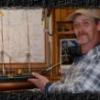
During the "house call" at Floyd's Shipyard I was able to catch the man in the action...... sort off
In the background his lovely dog Willow but also the J-yacht Endeavour.
This picture is good to give the idea of the sheer size of the yacht.
Floyd in action adding planks to the bulb and first two flush with deck.
The bulb planks measure 2x2mm while the regular planks are 1x4mm, that will result with a lot of sanding to get a uniformed side.
-
Elia reacted to fnkershner in J Boat Endeavour by fnkershner - Amati - 1:35
So here is an update on my progress.
First a couple of comments -
1. I decided to dispense with the drop keel. It only detracts form the wonderful lines.
2. As discussed in Sailor's log the instructions are very unclear about the first row of planking. but it appears we both agree that it should be flush with the false deck. There is a double wide strip that lays on the edge of the deck that will cover the seam.
3. I had a slight wow in the keel. And thanks to a house call from Dr. Per I discovered the problem before it was difficult to fix.
4. I had to add material to both sides of 5 bulkheads so that the first plank was flush.
5. I should also mention I plan to paint all of the hull. and there will be no 2nd layer of planking. Easy Peasy.
So without further delay -
-
Elia reacted to pete48 in Herreshoff Buzzards Bay 14' by pete48 - FINISHED - 3/4" = 1' - SMALL
First, I have to say that this has been one of those Builds that is hard to put down, Today I decided to make and install the decks, First I sealed up the forward compartments , Then I cut out the Decks and the Camber strips for on top of the bulkheads wich the deck will sit on, that way the deck will flow properly. Once the deck pieces fit to satisfaction they were glued into posistion . I then faired the deck with the Hull , and did a final Fairing . Now the exterior and deck are ready to be sealed with West System epoxy . I then dry fit the Coamings that were made yesterday , I still have not cut the sheer into them yet, The Coamings will be installed when I get to the finishing stage and at that time I will cut in the sheer . I wedged a peice of scrap to hold the Coamings snug and in place. Here are the results
-
Elia reacted to pete48 in Herreshoff Buzzards Bay 14' by pete48 - FINISHED - 3/4" = 1' - SMALL
Today I worked on making the cockpit coamings . First I finished installing the cockpit coaming backing on the fore and aft bulkheads. I then cut out the rear deck bracing ( as per plan ) Now the coaming's are the tricky part, there is no detail on the construction plan . ( other than the sheer profile ) I first made a template out of card board with the measurement s that were provided to me by the construction plan. I decided that my coamings would also act as the seat back, so my board would have to be wide . once the template was close I transfered it on 1/16" ( wich scales out perfect ) Material, soaked them in alcohol for 2 hours and bent them close to there location.( The coamings will be installed after the deck is on ) I left the top of the coamings tall, so that when the deck is on it will be easier to scribe the sheer ( because of forward deck camber makes it tricky at the transition point )Here are the results
-
Elia reacted to pete48 in Herreshoff Buzzards Bay 14' by pete48 - FINISHED - 3/4" = 1' - SMALL
Thank you David, Its been challanging and fun to build, shes right on the numbers so thats pleasing
Best Regards,
Pete