

.jpg.f26acc9a74319261612561bfa7da1303.jpg)
vaddoc
-
Posts
1,579 -
Joined
-
Last visited
Reputation Activity
-

 vaddoc got a reaction from Colin B in Hercules by vaddoc - 1:64 - Steam Tugboat
Thanks Mark and Jim and all that hit the like button.
A bit too early for an update but It's exciting seeing the shape of the hull slowly emerging.
Boats are such beautiful things!
Vaddoc
-
 vaddoc got a reaction from FriedClams in Hercules by vaddoc - 1:64 - Steam Tugboat
Thanks Mark and Jim and all that hit the like button.
A bit too early for an update but It's exciting seeing the shape of the hull slowly emerging.
Boats are such beautiful things!
Vaddoc
-
 vaddoc got a reaction from mcb in Hercules by vaddoc - 1:64 - Steam Tugboat
Thanks Mark and Jim and all that hit the like button.
A bit too early for an update but It's exciting seeing the shape of the hull slowly emerging.
Boats are such beautiful things!
Vaddoc
-
 vaddoc got a reaction from wefalck in Hercules by vaddoc - 1:64 - Steam Tugboat
Thanks Mark and Jim and all that hit the like button.
A bit too early for an update but It's exciting seeing the shape of the hull slowly emerging.
Boats are such beautiful things!
Vaddoc
-
vaddoc got a reaction from Colin B in Hercules by vaddoc - 1:64 - Steam Tugboat
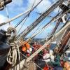
Time for a wee update!
I did lots of work but have little to show, planking is a slow, labour intensive process. I need to cut the plank patterns for each side separately as the port and starboard planks are very close but not identical. I try to fit the edges reasonably close but I am not too fussed, with a bit of sanding and filler it will be fine. Also, I really should have hollowed the planks where they meet the frames at the turn of the bilge but it will be fine. The plank scarfing is a bit wonky but this will also be ok with some sanding.
I realised that to progress further I had to mark all the remaining planks. One of the aft frames looked (and still looks) a bit wrong so I cut some of it off and overall I am not sure how the stern will end up, so some head scratching there is needed. Also, the sheer plank will continue as gunwales so this also needs some more thought.
I am not sure I have enough pear to finish the planking, I ve managed so far not to waste any wood but today I made two wrong planks - this is a lot of waste!
5 planks are in and the run of all the remaining planks marked. Of course the width of the planks is all way off scale but Hercules had a metal hull and I just want to plank the hull - there is no reason though not to do it nicely!
I think the planks so far run reasonably fair. The sheer also looks ok.
Please do excuse the huge mess in the yard!
Now, I may have a £200 gift card to spend and some money to add to it - I may get a milling machine! (Proxxon MF-70?)
Best wishes to all
Vaddoc
-
 vaddoc got a reaction from Ras Ambrioso in USS Cape (MSI-2) by Dr PR - 1:48 - Inshore Minesweeper
This was very interesting Phill (and very well done!). I also had never heard of sacrificial sheathing before.
Somehow though, I kind of think that, even though the expertise existed to properly spill and bend planks, it would be unlikely to spend time and effort in a military vessel, especially for a sacrificial layer that would not contribute to hull strength or water tightness. I think they just screwed the timber in, any way it seemed more time and material efficient, not far of what you ve done.
Vaddoc
-
vaddoc got a reaction from FriedClams in USS Cape (MSI-2) by Dr PR - 1:48 - Inshore Minesweeper
This was very interesting Phill (and very well done!). I also had never heard of sacrificial sheathing before.
Somehow though, I kind of think that, even though the expertise existed to properly spill and bend planks, it would be unlikely to spend time and effort in a military vessel, especially for a sacrificial layer that would not contribute to hull strength or water tightness. I think they just screwed the timber in, any way it seemed more time and material efficient, not far of what you ve done.
Vaddoc
-
 vaddoc got a reaction from Canute in USS Cape (MSI-2) by Dr PR - 1:48 - Inshore Minesweeper
This was very interesting Phill (and very well done!). I also had never heard of sacrificial sheathing before.
Somehow though, I kind of think that, even though the expertise existed to properly spill and bend planks, it would be unlikely to spend time and effort in a military vessel, especially for a sacrificial layer that would not contribute to hull strength or water tightness. I think they just screwed the timber in, any way it seemed more time and material efficient, not far of what you ve done.
Vaddoc
-
 vaddoc got a reaction from Valeriy V in Hercules by vaddoc - 1:64 - Steam Tugboat
Thank you all for your likes and replies and taking the time to visit.
@Jim Lad Jim it really makes a big difference, having the extra real estate around the saw but figuring out how to make the bench was a pain!
@Bedford I could and should have used 0.8 ply but I had already finished the CAD design, it would need more frames and most importantly true 0.8 mm seems to have disappeared - most of it apparently comes from Russia. Good to know though that Scissors can cut it cleanly - never thought of it. Def one to remember.
Now, lets talk Planking!
I cut both garboards and steamed them in place. I ve never steamed pear wood but it responded superbly. I used my steam box to heat the planks - worked really well.
I then scarfed the ends and secured in place with screws, The ends however had to be glued as the hull is not thick enough. Due to uneven surfaces I used epoxy - very messy solution but I do not think there is another. I think they came out alright!
I really like planking. For this boat, I did not really spend much time planning, I just eyeballed it a bit. I have only marked half of the hull but I feel pretty
confident. So let me share my method of spilling planks.
First I use 1mm (or 1.5 I am not sure) cardboard to make a pattern. I am only interested in the side of the plank that meets the plank already installed.
The foreword part of the plank has a lot of twist along its axis.
To get the correct shape of the edge, cut a strip of cardboard roughly the correct shape and run dividers along the edge of the plank already installed.
Then cut along the line with a knife
Fitting the pattern, it is a bit off - mark the high spots
Lightly sand the high spots, fit again, sand again etc. Now it fits fine
Connect with the previous plank using cardboard and glue and move on to next segment.
For the aft segment, the process is repeated - it just happened my rough cut pattern was spot on here!
The plank is now completed - the upper edge that is
Usually, I would just cut the plank as a single very long one but I would like to reduce wastage of wood.
So now lets cut the individual segments. First we transfer the shape of the upper edge to wood, making sure we mark the positions of the frames.
Then we measure the distances from edge of previous plank to line on frame and transfer over to wood
Using a baten, we connect the marks making sure the line is fair
Our plank segment is ready
Next cut the plank, test fit, mark and sand any high spots, fit again etc. Later on we will need to also take into account bevels and also curvature of frames - either sand concave the inner surface of planks or sand flat the frames.
Same process for middle and aft segments
All segments are ready, just the scarfs are needed.
The plank on the other side needs to be again cut individually as it is a close but not exact fit.
On a different boat I would have spent more time arranging the run of the planks but for Hercules, I think this will work well - the plank shape so far does not seem horrible.
I hope this was interesting!
Till next time
Vaddoc
-
.thumb.jpg.6fd4c1b78768bb3efd745ab810936005.jpg) vaddoc reacted to Jim Lad in Hercules by vaddoc - 1:64 - Steam Tugboat
vaddoc reacted to Jim Lad in Hercules by vaddoc - 1:64 - Steam Tugboat
Worth the time its taking, Vaddoc. That planking looks really good.
John
-
vaddoc reacted to Mark Pearse in Hercules by vaddoc - 1:64 - Steam Tugboat
Hi Vaddoc
That's looking very good. The line of the planks looks lovely, a difficult thing to get right.
Mess = busy
-
vaddoc got a reaction from FriedClams in Hercules by vaddoc - 1:64 - Steam Tugboat
Time for a wee update!
I did lots of work but have little to show, planking is a slow, labour intensive process. I need to cut the plank patterns for each side separately as the port and starboard planks are very close but not identical. I try to fit the edges reasonably close but I am not too fussed, with a bit of sanding and filler it will be fine. Also, I really should have hollowed the planks where they meet the frames at the turn of the bilge but it will be fine. The plank scarfing is a bit wonky but this will also be ok with some sanding.
I realised that to progress further I had to mark all the remaining planks. One of the aft frames looked (and still looks) a bit wrong so I cut some of it off and overall I am not sure how the stern will end up, so some head scratching there is needed. Also, the sheer plank will continue as gunwales so this also needs some more thought.
I am not sure I have enough pear to finish the planking, I ve managed so far not to waste any wood but today I made two wrong planks - this is a lot of waste!
5 planks are in and the run of all the remaining planks marked. Of course the width of the planks is all way off scale but Hercules had a metal hull and I just want to plank the hull - there is no reason though not to do it nicely!
I think the planks so far run reasonably fair. The sheer also looks ok.
Please do excuse the huge mess in the yard!
Now, I may have a £200 gift card to spend and some money to add to it - I may get a milling machine! (Proxxon MF-70?)
Best wishes to all
Vaddoc
-
 vaddoc got a reaction from Bedford in Hercules by vaddoc - 1:64 - Steam Tugboat
Time for a wee update!
I did lots of work but have little to show, planking is a slow, labour intensive process. I need to cut the plank patterns for each side separately as the port and starboard planks are very close but not identical. I try to fit the edges reasonably close but I am not too fussed, with a bit of sanding and filler it will be fine. Also, I really should have hollowed the planks where they meet the frames at the turn of the bilge but it will be fine. The plank scarfing is a bit wonky but this will also be ok with some sanding.
I realised that to progress further I had to mark all the remaining planks. One of the aft frames looked (and still looks) a bit wrong so I cut some of it off and overall I am not sure how the stern will end up, so some head scratching there is needed. Also, the sheer plank will continue as gunwales so this also needs some more thought.
I am not sure I have enough pear to finish the planking, I ve managed so far not to waste any wood but today I made two wrong planks - this is a lot of waste!
5 planks are in and the run of all the remaining planks marked. Of course the width of the planks is all way off scale but Hercules had a metal hull and I just want to plank the hull - there is no reason though not to do it nicely!
I think the planks so far run reasonably fair. The sheer also looks ok.
Please do excuse the huge mess in the yard!
Now, I may have a £200 gift card to spend and some money to add to it - I may get a milling machine! (Proxxon MF-70?)
Best wishes to all
Vaddoc
-
 vaddoc got a reaction from JacquesCousteau in Hercules by vaddoc - 1:64 - Steam Tugboat
Time for a wee update!
I did lots of work but have little to show, planking is a slow, labour intensive process. I need to cut the plank patterns for each side separately as the port and starboard planks are very close but not identical. I try to fit the edges reasonably close but I am not too fussed, with a bit of sanding and filler it will be fine. Also, I really should have hollowed the planks where they meet the frames at the turn of the bilge but it will be fine. The plank scarfing is a bit wonky but this will also be ok with some sanding.
I realised that to progress further I had to mark all the remaining planks. One of the aft frames looked (and still looks) a bit wrong so I cut some of it off and overall I am not sure how the stern will end up, so some head scratching there is needed. Also, the sheer plank will continue as gunwales so this also needs some more thought.
I am not sure I have enough pear to finish the planking, I ve managed so far not to waste any wood but today I made two wrong planks - this is a lot of waste!
5 planks are in and the run of all the remaining planks marked. Of course the width of the planks is all way off scale but Hercules had a metal hull and I just want to plank the hull - there is no reason though not to do it nicely!
I think the planks so far run reasonably fair. The sheer also looks ok.
Please do excuse the huge mess in the yard!
Now, I may have a £200 gift card to spend and some money to add to it - I may get a milling machine! (Proxxon MF-70?)
Best wishes to all
Vaddoc
-
vaddoc reacted to Jim Lad in Hercules by vaddoc - 1:64 - Steam Tugboat
You're making excellent progress.
John
-
vaddoc reacted to Dr PR in USS Cape (MSI-2) by Dr PR - 1:48 - Inshore Minesweeper
I have almost completed the sheathing on the starboard side. I am waiting to see if this works out before continuing on the port side.
CAUTION! This planking pattern is speculative. The blueprints say the entire hull below the boot topping had an extra planking of 3/4 inch red oak planks that were spaced 1/4 inch apart, with nothing in the gap between them. Other than that there are no instructions how this sheathing was to be installed. As noted above these planks were not tapered at the ends. So this is my best guess (and only a guess) as to how to apply these planks!
In the photo above you can see that when the planking parallel to the top of the boot topping is extended below the bilge keels it comes together at an angle. And there is planking parallel to the keel and garboard strake that also intersects the upper planking at an angle.
You can see in this photo the sheathing does angle downward at the bow, just like in the photos of the modern day Cape. The lower planking has a bit of an upward curve as it comes to the bow. It was apparent that something had to give, and some of the planks must be cut at an angle to join with the others.
But how? After thinking about this for a while I came up with the idea of joining them in a herringbone pattern, alternating between the upper an lower planking.
Here you can see the junctions between the planking (left) with red lines to outline the herringbone pattern (right).
If you look closely in the photos above you can also see I have planked the garboard strake and the keel with sheathing. But as instructed in the blueprints I didn't sheath the worm shoe at the bottom of the keel.
This section of a blueprint shows how the sheathing fit around the garboard strake and keel. The more or less horizontal planks were installed first, and the vertical side trim was applied next. Cutting and fitting these pieces was tedious and tricky!
The real problem is shaping up at the stern along the skeg/deadwood and stern frame (propeller and rudder frame).
The blueprints show clearly that the sheathing planks on the skeg were parallel to the bottom of the keel. It was easy to fair the sheathing on the garboard strake into the sheathing above and below it, carrying the planks straight out to the stern frame. But as these planks come out onto the body of the hull they develop a significant curve (requiring wet heat for bending).
The planks laid parallel to the boot topping are bending inward toward the center line near the stern. But the curvature is not as great as the planking meeting the skeg. The gap at the narrowest point (arrows) is three planks wide, so the upper and lower planking will come together nicely, except for a triangular space that will require a filler/stealer.
The upper and lower planks come together at an angle, so they will have to be trimmed in a herringbone pattern like I have done at the bow. But it is a very narrow angle, requiring the planks to be cut to a sharp point. And as we all know, this is supposed to be a no-no! But I really don't know what else to do given the constraints on the sheathing planks.
Is this a perfect solution? How can it be when I don't even know what it was supposed to be!? Is it a good solution? Maybe, maybe not. But it does allow me to move on past this part of the build and get on with all the complex deck houses and minesweeping gear. I have already started on the CAD drawings!
-
 vaddoc reacted to FriedClams in Pelican 1943 by FriedClams - 1:48 - Eastern-Rig Dragger
Thank you, Keith A, Paul, Jacques, and Keith B, for your comments and support! And thanks to all for the "thumbs up".
I’ve begun work on the Pelicans’ four gallows frames and this post describes some of the preliminary work.
The purpose of these frames is to hang the heavy tow blocks slightly over the side of the boat at about 4 to 5 feet above the main rail. The blocks function as tow points for the trawl and are also used to deploy and retrieve the gear with the main winch.
The screenshot below shows one of the frames outlined in blue. The green lines point out three braces that structurally secures the frame to the boat.
There are no details of these frames provided on the plans, so I drew up my own from a few basic dimensions I pulled from the plans and from photos of period boats.
I took the drawing apart to provide cutting templates for the individual components. The main legs are Evergreen styrene “H” columns, and the top plates were cut from .010”(.25mm) styrene sheet.
The pieces were arranged on the assembly templates and solvent cemented together.
There are several different types of brackets required for each frame and I made them all from brass. After drawing them in CAD, I began by slicing brass sheet into strips of the required widths. In the past I’ve made strips using shears (which curls and deforms them), or by scoring and bending until it fatigue breaks. I’ve even used a guillotine style paper cutter that in certain situations works fairly well. But these methods are not very precise and with some of these strips being quite narrow (.073”(1.8mm)), I wanted to try something a little different.
I used a stainless steel sheet (cutting surface), a carpet knife, a stout straight edge, and 2” wide double sided masking tape (sticky on both sides.)
The secret sauce is the heavy duty masking tape. One piece of tape holds the brass to the stainless and a second piece holds the straight edge to the brass. The tape holds everything very tightly in place to the extent that the straight edge is quite difficult to remove and reposition for the next cut. One could easily bend and ruin a thin metal straight edge doing this.
The setup below is ready for slicing off a quarter inch strip, and as you see from the score marks in the stainless, I’ve already cut several strips of various widths.
The carpet knife is sharp, hard and stands up to abuse like this far better than a hobby knife blade. And due to its geometry, the blade is less likely to chip off, but needless to say I wore proper eye protection. I found repeated light cuts produces a better edge than trying to blast through it with only a few. The brass here is .008” (.2mm) thick, so it only took about seven passes to free the strip from the sheet. The passes feel sticky until the stainless is reached at which time the blade glides easily through. This does leave a bur along the cut edge, but a few swipes with a fine flat diamond file licks them right off.
First to be made are the six bracket pairs (12 total) that secure the gallows frame bracing to the whaleback or pilothouse structures.
The strip is stuck to the template with two-sided cellophane tape and the fold and cut lines are scratched on.
The bracket is clipped from the strip with flush-cut diagonals and the edges are eased with a diamond file.
A bolt hole is drilled through with a pin vise.
The piece is placed into a photo etch bender.
Positioned and squared up.
Then bent.
The gallows have brackets at their feet to allow them to tilt out over the rail.
Eight pairs (16 total) of these will be needed. Holes for the bolt shanks will be drilled later.
A pair of brace brackets on the back side of the frame.
A total of eight brackets are needed.
Each frame gets two chain cleats. Soldered phosphor bronze.
The rod that extends from the center of the cleat will be clipped to length once installed.
And the rod loop which the tow blocks will hang from.
More prep work to be done on these frames, but that's it for now.
Thanks for looking. Stay well.
Gary
-
vaddoc reacted to FriedClams in Pelican 1943 by FriedClams - 1:48 - Eastern-Rig Dragger
Keith B, Paul, Chris, Druxey, Bowwild, Glen, Keith A, Andy, Marc and Rick - I thank you very much for the compliments and support. And thanks for all the "thumbs up" and to those watching quietly.
A brief update.
The wave break diverter that I installed in the last post has been removed and replaced with one of a different design. The original one is something that might have been installed on a metal hull boat, but never on a wooden fishing vessel of this era. The Pelican’s plan set shows a side view of the diverter, but no details or even a top view and what I ended up building was simply wrong. Further research showed the wave breaks on these wooden draggers were built directly onto the deck and not constructed in a shop and then bolted on.
The images below show the before and after.
Creating the new wave break was the easy part. Fixing the deck after tearing off the old one was the hard part because chunks of the “rubber membrane” tissue came off with it. Heavy sigh.
Moving on, I built the galley stove stack and the only info I have on it is the outboard profile. I lifted dimensions from the drawing but placed an alternative cap on top instead of the conical diamond shaped one shown on the drawing. The lower half of the stack has a double wall which allows hot air to travel up between the two pipes and exit at the beveled cap where the outer wall terminates. This helps protect the crew from burns when brushing against it.
It's made from brass and two modified plastic pieces from a Grandt Line boiler stack.
Solder and glue.
Once I knew how it would stand above the deck, I soldered on a deck collar. Then blackened, oil paints and pigment powders.
A hole was cut through the deck and the stack inserted. It still needs a support bracket off the doghouse and some butyl or tar at the deck. But deck wear patterns around it and deck weathering in general will be done after all other objects and details are in place. Meaning, not for a while.
Thanks for stopping and take care.
Gary
-
vaddoc reacted to FriedClams in Pelican 1943 by FriedClams - 1:48 - Eastern-Rig Dragger
Greetings Fellow Modelers,
Thank you Valeriy for your kind words, and thanks to all for the "likes."
Here’s an update on the Pelican’s whaleback. First, the toerails along the P/S edges of the deck are cut to shape then heat bent.
Next, the ventilator and its mounting/rotation flange got some color. I used a product on the cowl from AK Interactive that I’ve not tried before called True Metal. This paint was recommended to me by @TOM G and it works great although I haven’t yet mastered how to apply and polish it for best results. It’s a wax based colorant similar to Rub’n Buff, but whereas that product is more of an architectural hardware restorer, True Metal paint is produced for the model hobby and comes in a dozen or so colors that modelers can use. An interesting product that so far, I like – thanks Tom.
The cowl below is a mixture of TM “steel” and “iron” applied with a colour shaper. Almost looks galvanized.
A beveled coaming/plinth is added.
The “wave break” is a diverter whose purpose is to keep water coming over the bow from flowing aft onto the main deck. It’s made from .03” (.76mm) sheet styrene which scales to about 1.4” (36mm) thickness.
It’s dirtied up a bit and holes were drilled at each bolt-down location. The unit was temporarily located on the whaleback and selected bolt-down holes were drilled through into the deck.
Leaving some of the bolt shanks provided a foolproof way to affix it without concern of getting glue smear on the deck surface. Bolts are Grandt Line 5113.
The stemhead fitting is brass with a scale thickness of about .5” (13mm) and the eyes are flattened wire. One of the wires will be clipped flush on the backside and the other will penetrate the wood stem.
A port side deck ladder is made of .035” (.9mm) brass rod and finished with Jax Flemish Gray.
The ladder receives two styrene mounting brackets and weathering pigment.
Two 40” (102cm) tie off cleats will be primed then painted with True Metal on top. I drilled into the bottoms and glued in stubs of brass wire for deck attachment.
Then all of the above was glued to the model.
Trim pieces were added here and there. All of it is basswood except for the half-round styrene on the right.
A wider strip of half-round styrene was added as a rub rail just below the deck surface. This strip also secures the rubber membrane flap that folds over the deck edge.
Thanks for stopping by for a look.
Be safe and stay well.
Gary
-
vaddoc reacted to FriedClams in Pelican 1943 by FriedClams - 1:48 - Eastern-Rig Dragger
Paul, Keith, John and Dan, thank you for your kind and generous comments and to all for the "likes".
3D modeling seems to be popping up everywhere in scale model building so it’s time to give a try. I’ve always enjoyed the process of hand scratching detail parts, and I have no intention of giving that up. But I’m also aware of my limitations and previous projects have suffered from some ham-handed constructions and 3D modeling will help solve this problem. So, the Pelican will be a mix of printed and handmade details. I designed all the printed parts used in this model specifically for the Pelican. It is solid modeling done with FreeCAD.
I created the files but didn’t do the actual printing myself. I don’t see myself using a 3D printer enough to justify owning one, but that could change as consumer units continue to improve and drop in price. Anyway, I uploaded all my STL files to a commercial printer (Print a Thing) and the parts were delivered in less than a week. The total cost for these printings was around $33 US including shipping, tax and setup fees. I ordered extra copies of each part thinking some might be deformed due to their tiny size and fragility, but this was unnecessary. These are likely all the parts I’ll be printing for this model unless I run into trouble scratching something.
So here they are and just as I received them. No cleanup has been done to them. Stereolithography (SLA), opaque white resin.
Below are the deck mounted winch cable guides. It would have been an effort to scratch one of these from styrene let alone four of them identically. I left off the bolt-down washers and hex heads because they wouldn’t have printed well in this scale. Instead, I’ll place injection molded bolt heads from either Grandt Line or Tichy Train.
Here they are on an actual dragger (circled on the right).
Above on the left is a different cable guide under one of the four gallows frames.
There are three different warping/gypsy heads.
I have about 14 cleats of several different sizes. The two largest shown here are monsters (40” (102cm)) that bolt to the deck on top of the whaleback. I didn’t realize cleats were made that large. This is another example where making two precisely the same would be a challenge – as least for me it would.
The main winch cable drums, brake drums, pinion and bull gears. I only need one each of the gears, but I created different width versions because I haven’t thought through the details of the winch yet. The spooling drum diameter is very large in relation to its flanges, and I did this to reduce the amount of cable I’ll have to wind.
And finally, the air intake cowls. The forward cowl has an integral mounting and rotation flange, but for the engine room intake I created the flange separately so I can adjust the height as need be. It’s the same cowl with a longer duct pipe. I added hex bolts to these flanges and with the naked eye they look alright, but under magnification look more like rivets.
My initiation into 3D modeling design was a positive experience and only left a few minor scars. It is rewarding to create parts unique to a project that could have been a real pain to make or at least to make well. There is certainly a learning curve with 3D modeling and at times I was perplexed. But eventually all the loose marbles in my head found holes to drop into and the light bulb turned on. It’s easier than you might think.
Now back to the boat model.
Thanks for looking.
Gary
-
vaddoc reacted to FriedClams in Pelican 1943 by FriedClams - 1:48 - Eastern-Rig Dragger
Greetings friends. Thanks to all for your visits, the kind comments and the "likes". It is great to be able to share a hobby with such folks as you and I hope you all have a great 2025.
@Keith Black - please forgive my negligence in thanking you for your holiday wishes. You are very thoughtful, and I sincerely wish you and Maggie a happy and healthy new year.
Whaleback Continued
Well, I haven’t accomplished a great deal on the Pelican since the last posting a month ago, but here’s what I have got done.
Continuing on with the bow whaleback, I’ve enclosed the structure with side planking and roofing. But before I was able to do that, I first needed to install the main rail for it to sit on. The rail is made of two wood strips laminated together which together scale to 9” in width by 3”. Even though this lamination creates a seam down the rail’s center, it will eventually be covered buy additional rail, caps or in the case of the whaleback, planking.
I cut profiles of the forward rails from corrugated cardboard and glued them to a larger flat piece of corrugated. The wood strips were glued together with PVA and pinned against the cardboard profiles.
They were then attached to the boat. In the photo below the aft wall of the whaleback is already in place but getting it in there was an unanticipated fight.
Before the rail, the section simply dropped straight down in.
After the rail was attached, one end of the wall had to be fitted around it and then the other end swung into place.
But the opposite end could not swing into place because it couldn’t clear the bulwark stanchions no matter how I tried to bend and wedge the wall past it. I ended up breaking the wall into two pieces, fitting the opposite end in and then gluing it back together. The break can be seen below in the vertical siding.
Next, the P/S side planking.
Each was made of three individual planks edge glued together, then cut to shape and finally heat bent.
Four roof/deck beams were bent and cut. I added gussets to the longest two so the bend can’t relax.
The roof is outlined in red in the drawing below. Note that it overhangs the front of the companionway doghouse and extends to (and partially surrounds) the forward mast.
This roofing structure was made off the model and in two pieces. The main section of roof/deck is scale 3” x 2” boards glued to paper but not to each other.
The doghouse section is made of thinner material of the same width. The flat overhanging portion is edge glued and will eventually have visible underside structure.
The sections are glued to the boat with generous amounts of PVA and the main roof is trimmed and sanded flush to the side planking. Wood that was bent to match the slight arc of the roof was attached to the square cut boards to extend the overhang and provide structure for the fascia and other trim that will be added in the future. Below, the ends are still untrimmed.
In the era this boat was built, there were three ways wooden boat roofs were typically waterproofed. One was to mop hot tar or pitch on it. A second method was a covering of canvas tarps treated with oil-based paints. And finally with sheets of thin rubber membrane. I don’t know for certain how the Pelican’s roofs were done, but I’m going with rubber for its durable and also because the other two methods seem antiquated this late in the period. But what do I know?
I began by painting everything flat black. Once that was dry, I smeared a 50/50 water/PVA mix on and then laid down three strips of tissue paper (gift wrapping type) before it had a chance to dry. To be accurate, I actually did this in three sections. I painted on glue to the port side and then laid a single tissue strip over it. Then I did the starboard side and finally a strip down the middle and over the doghouse. I might have been able to lay it all in one go, but this process gave me the time to fuss with the tissue paper and obtain the consistency of wrinkle I was after.
Letting it sit overnight, I then painted the tissue a charcoal black acrylic followed by a faint and heavily diluted wash of dirty white pigments. The waist edges were then trimmed off with a razor blade. Some of the roof boards telegraph through the tissue and the overlapping seams are obvious yet don’t look out of scale to my eye. This image also shows the quarter circle roof corners that I didn’t think to photograph when I installed them earlier.
There is much more to do on this whaleback - many details and finishes - lots more.
Thanks for taking a look. Be safe and stay well.
Gary
-
vaddoc reacted to FriedClams in Pelican 1943 by FriedClams - 1:48 - Eastern-Rig Dragger
Greetings Fellow Modelers. Thanks for the "thumbs up" and for stopping by.
Hey Keith - no I don't turn them on very often at all. And actually, once I finish a model, I rarely even look it again except in passing. The fun was in the building, and I don't need to see things I wish I'd done differently. A few years ago, I started building small shadowbox scenes where lighting is important, and I've carried some of that over into fishing boats. It's pretty quick and easy to do so - why not. And I have noticed that casual model viewers seem to really get a kick out of it.
Whaleback -part 1
In the context of an Eastern-rig dragger, the whaleback is an elevated bow structure that provides a measure of protection for the crew when working the open deck in heavy weather. The structure also adds storage space on the main deck for spare gear such as netting, chafing and roller gear, twine, cable, etc. A whaleback was typically only built on larger draggers and sometimes mid-sized boats like the Pelican. In the drawing below, the perimeter of the whaleback is high-lighted in blue. The aft wall sections (darker blue) are what I'll be modeling in this post along with the companionway doghouse outlined in green.
I began with the small walled in section that extends aft of the main storage space and butts up to the backside of the companionway doghouse. There is no passage between these two structures. Entry into this space is through the main storage area of the whaleback only. It is a rather curious little space where the crew stored the deck chairs and chilled bottles of chardonnay – or not. Joking aside, in subsequent years this spot held the fuel tank for the galley below, presumably kerosene. I'm a bit surprised that this boat in the mid 1940s was still using coal for this purpose.
Anyway, I drew up the wall sections and glued pre-stained siding to the template and cut them free.
Like all things in boat model building, nothing is square, level or straight. This structure leans toward the bow mirroring the sheer.
The main wall framing is drawn up with its lower edge conforming to the crown of the deck. The top of the wall will be a landing spot for the roof and is more severely domed.
The wall is constructed and the previous assembly glued to it.
The partition needs planking.
And the walls need doors. These doorways are short and potential head bangers, about 4’4” (132cm).
The doors (and everything else) were brush painted with Tamiya flat white acrylic with a touch of red and yellow to warm it just a bit. The hinges came out of my junk box without packaging but are undoubtedly from Grandt Line. They're painted with Testors “flat steel” enamel and rust colored pigment powder was daubed on while still wet. The latch bracket is blackened .01” (.25mm) brass.
Painted and glued together.
Someone left the starboard door unlatched.
The companionway doghouse is drawn and assembled using up wood strip scraps.
The structure has two small portholes with 8” dia. openings made from slide fit brass tubing slices.
The outer tubing has a thicker sidewall and pretends to be a mounting flange. The holes in the siding that accept the lights were drilled through first and expanded with a tapered file, then test fit.
The doorway threshold stands 12” (30.5cm) above deck to keep storm water from cascading down the companionway. The structure has 12” wide vertical boards attached to the doorway corners at an angle of about 45 degrees. Their purpose is unknown to me, but because it’s a two-piece center opening door, I suspect they act as stops and keep the hinges from being torn off in windy conditions. Also, they are tapered at the bottom to reduce trip hazard. Speaking of trip hazard, the wire rope cables leading to the forward gallows frames cross inches from these boards about ten inches above the deck (see drawing at top of post.)
The structure gets paint, the portholes are glued in, and a small piece of microscope cover slip glass is attached to the backside for glazing. The glass is 0.13mm thick. The brass portholes were only blackened long enough to take the shine off, and the outer ring was left a little proud to represent a surface mounted flange.
The door is constructed. It is 26” (66cm) wide by 58” (147cm) tall.
Grab irons are made from .02” (.5mm) phosphor bronze wire treated with Jax Flemish Grey. The pipe flange wall mounts are injection molded washer/nut sets from TichyTrain. I filed most of the nut off and drilled them out. Chrome enamel paint.
The chipped and missing paint on the siding is achieved by applying cellophane tape and then ripping it off like an old bandage. I burnish the tape down with a fingernail in areas where I want more of the paint removed. By staining all the wood prior to painting, this process reveals wood that looks aged.
Soldered railings. Again, phosphor bronze wire. This stuff won’t sag as easily as brass will.
Placed on but not glued to the boat.
After it is permanently attached, I’ll add base trim.
Next comes the roof (or would that be deck?) and a bunch of other stuff.
Thanks for looking.
Be safe and stay well.
Gary
-
vaddoc reacted to FriedClams in Pelican 1943 by FriedClams - 1:48 - Eastern-Rig Dragger
Greetings
After several months of doing little on this model, I'm moving forward again.
The covering boards have been installed forward of midships. They are pieced together between the top timbers and the inside margin is a single strip. I did it this way because the thick deck planks were difficult to cut crisply around the top timbers. But I would not do it this way again.
The top timbers are irregularly spaced in this area to accommodate the freeing ports as per the plans.
Airbrushed with thinned Tamiya flat white – 2:1. It looks gray below, but it is white. Later I added a little dirt with pigment powder.
Coamings for the fish hold hatches were made from 12” x 3” material. From the side they are parallelograms to compensate for the deck sheer. These are only the lower portions of the coamings, and they will eventually be heightened to 21” above deck.
The 12” king plank was placed and a hole for the forward mast was cut. The hole was first pilot drilled then carefully enlarged with a 1/4” burr chucked into a pin vice. The burr cuts too aggressively, so I turned it counterclockwise into the wood. The burr is abrasive enough that even being rotated in the opposite direction still burrows a smooth and perfectly round hole into the soft wood.
The plank was painted white on top of gray then scraped with the edge of a safety razor set almost perpendicular to the plank.
The deck planks are stained a natural wood color as a base.
Then gray paint was scrubbed on top. I added about 10 percent yellow to shift it away from blue. I applied the paint heavier is some areas and practically dry-brushed on in others.
I began adding deck planks from the center outward. The planks are 4” wide by 3” thick and were painted black on bottom and sides to help keep the fish hold lighting from escaping. This is not the final deck finish. After all the planking is installed, it will be repaired as needed, scraped, wear patterns added and weathered.
This section of deck has four bunker plates and two smaller deck inlet plates. The lids for the bunker plates have already been made and the process that I used is shown back on post #124. They were made from polymer clay and enclosed by a perimeter brass ring.
Similar to a manhole cover, these lids fit into ring frames. The frames are made of three slide fit brass tubes that combined provide the wall thickness required.
Soldered.
Cut from the tube and treated with Jax Flemish Gray.
The lids are epoxied into the frames – one will be left open.
The deck inlet plates are considerably smaller and have 10” dia. openings. The plans label the port side plate "ice" and is positioned over a walk-in refrigerator. The starboard plate passes coal to a bin in the galley next to the cook stove.
The plates are made from brass tube, wire and styrene.
I made a section of deck for each side of the boat and cut holes for the deck plates off model. I did this to avoid getting wood chips and sawdust down in the fish hold.
I began by creating a positioning template in CAD.
I glued planks directly to the template. I could have glued them to a blank sheet of paper, but this insured the edges were straight and the combined width was correct from end to end.
I then printed the same drawing on laser transparency and used it to locate the cutouts.
The bunker plate holes were drilled through then enlarged with a tapered reamer twisted counterclockwise. The edges were cleaned up with a diamond needle file.
With a tapered round file, the same was done for the smaller inlet plates.
Plates glued into place.
The other side was done the same way.
Thanks for looking.
Be safe and stay well.
Gary
-
vaddoc reacted to FriedClams in Pelican 1943 by FriedClams - 1:48 - Eastern-Rig Dragger
Greetings friends.
Thanks to all for the comments and "thumbs up".
Bulwark planking, scuppers and freeing ports.
I expected to have the covering boards and rail stringers on by now, but . . .
This fishing boat has a total of 104 scuppers and 8 freeing ports. The scuppers are 2” (5cm) in height and their width varies from 3” to 8”. There are three sizes of freeing ports, with the largest being 16” (40.6cm) wide by 9.5” (24cm) tall.
The bulwark planking above the deck is the same thickness as the hull strakes and the waist strakes just below the rail are significantly thinner.
Below is a closer look at the scuppers and ports at the forward deck. The cutouts are parallelograms that conform to the sweep of the sheer and their tilt angle is steeper the further forward they are positioned. The scupper cutouts below the gallows frame are almost as wide as the distance between the top timbers. Eventually they will be fitted with extensions that reach out through the vertical sheet steel that protects the hull from the heavy otter boards. Also, note the small freeing port in the sheet steel that has vertical bars instead of a hinged door.
I made up the bulwark planking in four sections – P/S above the forward deck and P/S above the aft deck. I began with the forward port and made myself a template for the cutout positioning between the top timbers. As per the drawings, the top timbers are set to 18” centers except in the areas where the freeing ports are placed, which require added width.
I printed out the template and checked registration against the “as built” top timber spacing by shadowing the timbers onto the drawing. I tweaked the drawing until it matched.
I initially tried cutting out the scuppers/ports from a single wide plank using a scalpel and safety razor. Bad idea - crooked, sloppy and inconsistent. The majority of the cutouts are 2” x 3” which in 1:48 equates to approximately 1mm x 1.5mm and getting a uniform look was difficult. So rather than subtracting material from a wide plank, I added the material to a "header" plank between the cutouts to build up the plank width needed.
The scuppers are of equal height, so the header plank provides for a nice even top edge. Many of the distances between cutouts are the same, so once I cut a wood strip of the correct dimensions to butt against the header plank, it could be used multiply times. I simply butt glued the strip to the header, chopped it to length with a razor blade and then moved it to the next location requiring that same width. Also, using the butt strips meant the vertical edges are always parallel and uniform. And to achieve the proper parallelogram tilt, I simply beveled the butt end of the strip as required.
The freeing ports were enlarged with a scalpel and needle files. I rough cut the area out then hardened the basswood with “super thin” CA and file finished it.
Next, the aft scuppers were done in a similar way, but because I cut them from thinner material and there are no freeing ports, I simply segmented a strip of wood and added back the spacing distances. Also, there is little or no parallelogram cutting needed.
I added the lower waist strake and then glued on the scupper strips.
At the stem, the waist strakes are sistered to increase the plank thickness for fitting into the rabbet.
Thanks for stopping by.
Take care and stay well.
Gary
-
vaddoc reacted to FriedClams in Pelican 1943 by FriedClams - 1:48 - Eastern-Rig Dragger
Greetings all,
Thanks so much for the wonderful comments, the thumbs-ups and for finding the time to visit this build.
Bulwark Stanchions
Before work could begin on the stanchions for the bulwark, I first had to finish up from the last post by adding five more deck beams where the span between existing beams was too great.
With that done, I started on the stanchions which the drawings refer to as the “top timbers.” This boat has 106 top timbers and are spaced about every 18” (45.7cm). In full disclosure, there are several details of these timbers that I didn't model because I felt there would be little return on the effort invested. First of these details is a taper of the timbers from 4.75” (12cm) at the deck to 4” (10cm) at the underside of the rail. In 1:48 that's a difference of .016” (.39mm), so I used wood that doesn't taper and scales to 4.5” square instead. Also, the drawings call for chamfered edges on the inside facing corners - very nice, but no. The most glaring omission is that I didn't bevel the outside and inside faces as they approached the stem and stern. In the image below, the top timbers below the red line are obvious enough that I should have beveled them, but I didn't. Forward of the blue line will be a raised “whaleback”, so those extremely beveled timbers are all hidden.
This is the profile of the whaleback (green) visible above the main rail (red).
And the same thing aft, but there are no beveled timbers as they round the stern and there is little discernible bevel moving forward through midships. If it sounds like I'm constructing a justification for not beveling any of the top timbers, you're onto something.
I made four off-model stanchion bulwark assemblies. One each for the port and starboard bulwarks forward of station #7 and two more for P/S aft of station #7. I created a template for each assembly based on the distance between bottom of deck at side and bottom of main rail.
The top timbers are at a right angle to the waterline, not the rail.
The angle of bend at each body plan station is found.
The upper waist strake for the bulwark section is bent to the proper arc and then attached to the template with double-sided tape. The top timbers are then glued to it.
The section of top timbers is affixed to the hull. Note that a strip of wood equal to the deck thickness has been glued to the upper most hull strake. The bottoms of all the top timbers are glued to its inside edge.
The final eight timbers at the stern were placed individually.
The scant number of timbers in the bow area were placed willy-nilly to temporarily hold the waist strake in its proper orientation until the bulwark is complete and the whaleback structure starts taking shape.
Next up – finish planking the bulwark, installing the inside rail stringer and fitting the covering boards (oh boy!).
Be safe and stay well.
Gary