

.jpg.f26acc9a74319261612561bfa7da1303.jpg)
vaddoc
-
Posts
1,605 -
Joined
-
Last visited
Reputation Activity
-

 vaddoc got a reaction from Colin B in Hercules by vaddoc - 1:64 - Steam Tugboat
Dear all
Time to revive this log!
@KeithAug Lol, no, no long vacation, just very limited time and almost all of it taken up by Tally Ho!
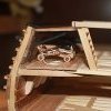
Ok, so I did a bit of work on Hercules.
I managed to finish the timber guard at the stern which was a bit tricky, I am not used to work at such small scales. I then installed the lower timber guard
Then I started work on the first level of the superstructure, lots of things going on there. I made the doors and drilled (very carefully!) the holes for the portholes- it was at that time I realised there is a staircase. After a bit of trial and error I managed to come up with something that painted black will look ok ish I think.
For the portholes I just bought cheap brass plumbing thingies that come in all dimensions. I experimented with Micro Kristal Clear for the glazing - excellent results.
I then made the cap rails, I used mahogany which is the wrong wood for the job but did not have anything else in 1.5 mm thickness and I am not ready to put in the massive wood order for Tally Ho. Everything will be painted black though so should be OK. I also made the stern structures and roller - All need to be painted and screws replaced with wood nails.
I then made the quarter bitts - still need a bit more work though
Really now it is time to paint the hull and make and paint the rudder so I know where exactly the steering mechanism at the stern needs to be placed. It is too cold though in the garage to spray primers and I do not really have permission from the Admiral for indoor modelling activities - or actually the time.
Still Hercules seems to be on the right track steaming along side Tally Ho.
Many thanks for visiting
Vaddoc
-
.thumb.jpg.6fd4c1b78768bb3efd745ab810936005.jpg) vaddoc reacted to Jond in Elizabeth Howard by Jond - 1:48 - The White Ghost - Schooner
vaddoc reacted to Jond in Elizabeth Howard by Jond - 1:48 - The White Ghost - Schooner
Phil
Nearly 10 years ago I made my second visit to Lunenberg to sail on Bluenose II. The day before our sail, they were rained out and I got to spend a good hour or more on deck with the crew taking a million photos and asking lots of questions. I also bought a copy of the book sharing all the detail of her design.
On one of the pages [copy below] there is a description of rigging that sail, the four corners do the following
• Peak halyard is continuous line that goes through a snatch block either port or starboard rail depending on the tack
• Throat halyard goes to pin rail
• The sheet leads down to aftermost dead eye…..I believe that means another deck snatch block to make it easier to handle, and again it would be either rail based on tack
• The tack is the most interesting and not possible to model. There is a hook that is lashed to the tack and secured to either of the foresail halyards. It is meant to slide up or down the foresail halyard and thus to flatten the staysail at mid point. The tack itself is belayed at the outer rails, again port or starboard.
In my studies I have found many similarities between The Bluenose information and new England Gloucester fishing schooners. There are a few differences as well. I will likely follow this wonderful detail as we all know outside of the Howard Chappell Fishing schooner book, there is little other information. If there is more out there, I would love to read it even it comes too late for my work.
Thanks for pointing our this issue.
Merry Christmas too
Jon
-
vaddoc reacted to Jond in Elizabeth Howard by Jond - 1:48 - The White Ghost - Schooner
15 reset the top masts with missing rigging, as sails go through early production.
1 this view shows me carrying on from the last update, I have added the missing foremast bands and blocks for the foresail and the hoops for the fore topsail. She is back together there at least. 2 shows the main top mast disassembled for the same treatment 3-4 these views show us all back together.
Going forward, I have reached the time when I need to set the stage as to how I would like to display this model. Surely as she was racing.
5-7 show three views of her that influence the intent. One option I have considered is to show the historical event where she lost her top formast in the first elimination race against henry Ford. I have researched that incident and learned that the mast did not fail but came unstepped. They rerigged it on the fly to to set horizontal but loosing both he top ails and the fisherman sail they had to retire. I will not try to do that but simply refer to the story of her closeness to glory. 8-10 these views show the production line of sails and spars. 11 this view shows an interesting option. I included the three racing photos also to document that no anchors were present while these guys raced. Thus, I may lash one to the deck, but will not hang one over the side. a final question will be how many crew do I need......I am not sure the typical collection of 4 or 5 will be enough. cheers
-
vaddoc reacted to Jond in Elizabeth Howard by Jond - 1:48 - The White Ghost - Schooner
14 getting all the spars ready for sails
Over the next month I hope the 8 sails will get made. In a parallel effort they need the spars for lashing and all the running rigging lines that need to go on before installation. Example would be the boom tackles or topsail clewlines, that are much harder to install on board, should go onto sails before they are rigged. A halyard could go on the sail or the gaff before but I find it easier after for the peak halyards to a gaff.
During the holiday, the sail patterns were made, and dry fit for adjustment. Since dimensions were taken from scaling photos, I was not surprised that every sail needed something trimmed; usually cut down.
1-2 show the patterns all made and after adjusting held in place for a look see. They were taken off as soon as the photo was taken. 3 -4 show that the top masts need to come back off [cutting and removal of dead eye lashing on top mast shrouds and other stay lashing needed. Dressing of the masts include bands and blocks at the top of the lower masts, hoops for the upper masts and more running rigging needed to be done before reassembly. This effort was understood to allow the timing for the sail making process that my daughter likes to do when she comes for vacation. Otherwise, the complete dressing of the spars would have been completed first. 5,6 ,7 show my selected process to make top mast hoops. I like to use 1/64 birch plywood strips for larger hoops, but found coiled packing tape over saran wrap on a Dowel of the selected diameter works well. I use a simple razor blade to trim off say 10 or 12 hoops. They then get coated in varnish and some need a little AC glue to tighten up the ends. This roil of tape will outlast my work by a century. The uncut tape stays on the dowel so I have about 4 diffewrne sizes waiting for the next job......sound familiar? 8,9,10 show my low-tech use of a mini mill to drill more accurate holes. Three images are the pear wood I chose for the jaws getting drilled for monofilament simulated bolts and the gaff band holes. View 4 is a foresail mast peal halyard ring getting drilled to hold a halyard block. all for now...first snow is predicted, let's see if it happens
-
vaddoc reacted to Jond in Elizabeth Howard by Jond - 1:48 - The White Ghost - Schooner
13B Standing rigging done
I have been working to get the standing rigging and spars all done, so as my daughter comes for Thanksgiving, we might have fun making sails. Her friend flew in from Arizona, so we have two helpers…oh boy.
1-3. The first three images are overall views just to record we are done. The main back stay on starboard is aft as we will display the schooner sailing on starboard tack. Without any sails up and sheets and preventers holding things down, it is the only line holding it all rigid. 4 -5 show the foremast starboard side all secured. next up of course are the ratlines. 6-7 show the bow sprit. This sprit was only added for racing. The foot ropes need to be completed. I have the furling tie offs. A detail I learned about while visiting Bluenose II. The planks to catch the sail and the preset lanyards to secure the sail make lots of sense. This rig is a racing rig as the scene to be set is the first elimination race against the Henry Ford , October 13,1922 When not racing the bowsprit was not even rigged as she was launched to be a knockabout schooner. 8. just a tease as the first sail is progressing through the assembly line. I need to finish up all the spars, so they are ready when the sails get done.
This sequence of rushing to secure and fasten everything is not a great sequence if rework is to be avoided. Once the patterns are done and test fitted for adjustments to allow sail making, there will be some disassembly needed. that will come in the next update.
cheers
-
vaddoc reacted to Jond in Elizabeth Howard by Jond - 1:48 - The White Ghost - Schooner
13a deck work and standing rigging moving along
As I now divide my time between this build and the 1872 Norwegian ship Gjoa, things are not so fast. It is fun though, as Gjoa is in the hull stage as this build is into deck furniture and starting the rigging. This is a partial update.
For most of my guidance I refer to the age-old favorite book o fishing schooners by Howard Chapelle. Several similar scale schooners in the past and the detail I learned building a bigger scale bluenose several years ago. One difference from Bluenose is, from the photos of Elizabeth, lashed dead eyes were used instead of turnbuckles. Perhaps the 5 years between 1916 and 1921 made the difference. I am therefore using lashed bullseyes for many of the fixed stays that surely would have needed adjustment.
To work
1-3 these images show my low-tech approach to building the sliding goose neck for the jumbo boom. I took a brass channel drilled a hole on top. Then I set a tiny rivet upside down and put a cut off brass eye with system through the rivet and the hole in the channel and soldered it up. I then soldered a clevis on the end of a rod to sink into the fore end of the jumbo boom. I also added some handles to control the winch [ imagined anyway] and some chain. I am not proud of the mechanism but is represents that something would have been there.
4-6 these images show progress making up the hardware and stringing the running rigging aloft. It is all left untied for now. When it is all in place I will have some extra hands here over the next holiday and we’ll square it all up, tighten and then lash all.
7 This image shows from the bow, the bowsprit and fore stay rigging is taking shape as well. I even put in all the belying pins -
vaddoc reacted to Jond in Elizabeth Howard by Jond - 1:48 - The White Ghost - Schooner
10 oops rework the deck based on review of photos
I mentioned above a dumb move / oops. I was in a hurry and somehow laid out both masts incorrectly. Based on that layout, I shaped the rails and included the pin rails. I took the model to the garage, so I could peck away each day a bit while summer guests made working in the shop not convenient. I posted the installed decking. I should have just waited.
Here is the sequence…..
01 returning to the shop, I proceeded to carry on and installed all the chain plates. Dumb!
Back at my shop computer, which coincidentally I replaced my long-gone computer at this same time. We all know that resetting a new computer means another week that I should have waited. I finally resumed studying all the available images to figure out how the deck was laid out. As I mentioned earlier through the net I found the several collections in both Gloucester and Boston Library collections. I “borrowed thumbnails” and blew them up, scaled spars etc. I had previously shared the sail plan that I did in cad months ago based on a broadside racing image. Why did I not use that drawing when I located the Mast? Who knows
02-05 In these photos one can see the relocated masts and re-laid decking. The foremast wrong hole is amazingly close enough to the round fish loading hatch with which I will plug the hole. The main mast hole was plugged and covered in new decking. The pin rails and chain plates were all relocated and are back together. At some point I need to do more remedial work, especially the outer hull where the chain plates were removed. The pin rails will be mostly covered with coiled lines so they will work out.
Going forward
Photos 6-8 To plan the deck work, here are two cropped images that come from different internet images and sites. When blown up, they give a reasonable sense of what was on deck and where. I also have one of our Historical Society photos of the sister schooner Louise Howard. The similarities carry through after scaling and measuring the sail plan. So they both confirmed the error made and after the fix I am ready to move forward.
cheers
-
vaddoc reacted to Jond in Elizabeth Howard by Jond - 1:48 - The White Ghost - Schooner
9 the deck
As I move forward into the deck work, I am fully dependent on just a few photos to understand the layout. Fortunately, a couple of photos showed me the lay of the decking followed the waterway inward. As to the furniture we will get to those assumptions later. Before I share a progress update, I would like to revisit the history of the two sisters. Elizabeth and Louise Howard were both built one after the other. As discussed, Elizabeth was extended about 6 feet in the bow for that little push of speed. Louise apparently retained the McManus 1908 Oriel design length of 126 feet.
1 this view is one of the better views of the Adams shipyard. It was taken in 1903 with the four masted schooner Eleanor Bartram in the shipways.
2-3 Here are two views of Louise sitting on the shipway with the harbor frozen in
4 here we see Louise just after launching. In the background we see The Rice brothers’ yard with their 1918 steel hull dragger Alden Mills. That dragger was one of 6 that they built. Last year I built a model of the 6th one Harvard.
Back to progress
6,7
I like to share my oops moments. In these two progress images we see that the predrilling of the main mast hole needed relocation. An advantage to running the planking inward from the waterways is one finds the real center. I stretched a thread bow to stern as the center became more evident, and that guided me in confirming the king planks location and the need to relocate the Mast hole. I dowelled the wrong hole and redrilled in the center. The benefit of 3/16” plywood under deck covered with about 1/8” poplar made this an easy fix.
7,8
here the decking is complete, and the sanding partly done. I progressively advanced in grits up through 320. There really isn’t grain to bring out in Alaska Cedar, but a rich color and shine that is hard to see in the photo. It is all amusing as the real decks of fishing schooners were really a mess. Also the summer invaders have gone and I am back to the model shop.
8-11
here are four images of the decking with two coats of hand rub Poly. I chose the poly because I find it more resilient to the abuse than the tung oil of my recent builds, which will occur while building out the deck. I also have started playing with the masts.
all for now
-
vaddoc reacted to Jond in Elizabeth Howard by Jond - 1:48 - The White Ghost - Schooner
8 time to get some white paint on her.
As we are in the peak of summer, I am moving the work from my shop to the garage. Before moving, I was under a time crunch to get the bulwarks done with as much detail as time would allow, so that after painting there would be less disturbance. I also want the move to follow a change in activity, so I am taking only one box of stuff with me and not my whole shop or worse running back and forth. First up is that preparation.
Then after the move yesterday out came the low-tech spray paint cans, “rattle cans” as I have heard them called. One coat of primer outside them three light coats of white. Inside just the white. I am studying the old photos to see if I need to repaint the waterways gray.
Things that I would have liked to have done first include the chain plates, lips on the hawse pipe, perhaps forward cavils and more dental work to get all the fuzzy edges all gone. I added a trim strip as found in the launch photo.
I will let it all sit for a day to harden up. Hopefully the enamel will last. My previous builds all needed much touch up. I want to learn how best to avoid that added process. While outside I will add the cedar deck and build a working cradle to hold her during that process. I am not sure how to mount her ultimately. She is not heavy but with the masts she will be over three feet tall. Brass pins drilled into the keel and then into a base I think is not wise for this build. I would love to figure out how to use acrylic to hold her as to me it is all about the ghost image. I don’t want a stained wooden cradle and I do not plan a diorama approach as i did on the Schooner Bowdoin.
I will add some shots after removing all the tape.
All for now…enjoy this brief summer.
-
vaddoc reacted to Jond in Elizabeth Howard by Jond - 1:48 - The White Ghost - Schooner
7 Bulwarks progress
Occasionally, something serendipity happens. One of my many projects continues as we are digitizing our local historical society documents and photographs. I am overlooking the photos. We are up to finding 16,000 so far. What I mean finding is that as one opens a storage sleeve marked with a label, we find just one or several prints negatives etc. As views are different, the index grows accordingly. At the beginning of this build I shared the image of the EH as she hit the water during, her 1916 launch. Some details are in the photo, but not with a lot of clarity. Last week I found the following image that I have annotated for this build. The print was sitting in sleeve marked East Boothbay waterfront. I was thrilled to find it. I am not sure how to make the little trim strips, but I will try.
Here are some progress images. I first secured a plank outside the raised deck, inserted the stanchions on one side at a time. I secured them with clamps on future plank stock. This process repeated four times and then the water ways went in. I filled in cut pieces between stanchions and then marked, drilled and set the scupper planks in place. Finally, I added the upper bulwark planks.
I end this progress piece showing I have now cut the stanchions back to the underside of the future rails. Just for fun I share the image of the new cedar deck planking that just came from the Sawmill. I love their material. There quite a bit of work before I get that that stage, but it is fun to look ahead. The first of our crew has shown up too.
Lots to clean up and then I need to complete the rails. The transom and bow need attention. I also want to lay out basic rigging so the side pin rails, cavits etc. can all be done before painting the topsides and the bullwarks.
All for now
-
vaddoc reacted to Jond in Elizabeth Howard by Jond - 1:48 - The White Ghost - Schooner
6 launch the hull and install under decking
I am doing a few new things in this build. Some steps may help, and some may not. We just must wait and see. First up there were about three more cycles of touch up putty, some more primer and sanding. Eventually at 800 grit, I called uncle. I took her back outside and gave her a new view of the water, before leaving on my second Canada adventure this summer.
Next was to paint the bottom and launch her. I followed some advice and bought some “frog tape” that says it gives a sharp line. Here we see my low tech set up for marking the water line. I also decided to build and add the rudder now. I think the waterline is better than previous…yeh for Frog tape.
To launch, I found an old RC sailboat sling in the shop to use. Before cutting off the bulkhead stands, I measured and marked a line 1 inch below the future rail at each bulkhead. There will be 4 stanchions between each mark. Then off with the stands. I then cut up the soft Luan plywood stand material to fill in for a complete under deck. A few extra hours here instead of figuring out where blocking will be needed for rigging eyes etc. The Holes for the stanchions are in as well. Finally, I am now in the process of the smooth under decking. This process means instead of perhaps 1/16 decking over many more hours off effort to get the under deck really nice, I use, 1/32 plywood and I ordered precut 3/64” cedar from the sawmill website. So, expecting a little sanding I am close to the 1/16th inch scale for the decking material. For the raised after deck I am adding 5/32 poplar. It will get sanded as well before decking. The cross beam at the step is cut down Alaskan Cedar. It is high now but i will sand it closer before decking.
We’ll have to see how this under deck and stanchions comes out. Once all is in place and sanded to clean up. I will install all the stanchions and bulwarks. Then I hope to paint all before moving on to the decking.
All for now
-
vaddoc reacted to Jond in Elizabeth Howard by Jond - 1:48 - The White Ghost - Schooner
2 First up are the sources for drawings.
I went to the Smithsonian catalogue and ordered the McManus design for both Oriole and Elizabeth Howard as prepared by Howard Chapelle. Note this is actually very easy to do once you have hold of their catalogue. It is unfortunate that it is not on line….[I think].
1. Here are the hull plans they shipped. They are basically at 1:32 scale just off a hair.
Before we get to the hull let’s gather all the other info we plan to use. There are no surviving drawings of the on-deck configuration nor sail plans, but artistic license should warrant a “close enough: / generic finishing above deck. So let’s find some photos. Here is before bowsprit and racing with a bowsprit.
2. this view is one of two images I am after….note there is no bowsprit in the image. This shows the working vessel.
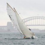
3 here we are racing in all her glory….the likely choice. The other option having no deck plans could have been to use the great hull drawings and do all the in between framing and show it in the yard under construction. I chose not to follow that approach for the "White Ghost" of Maine. I think it is the sailing image of such a short lived thoroughbred racer to be the better way to go, so off we go.
To complete my outreach at this point for the above deck, I will use two photo documents and will annotate them. Once again, I have taken a broadside photo and embedded it in cad and scaled it. I found it strange with the subtle roll to starboard of the hull in this image, the masts are absolutely plum. I will add a bit of a rake as can be seen above.
4 . here is screen shot.
5 by example of the next steps, here is the spar plan.
6 here is the first sail plan. I will later do one for each sail. Where like this mainsail where they are larger than tabloid 11”x17” my printer limits, I have added coordinates to lay out the pattern manually. Smaller sails will simply be printed. To place furniture on deck I will use the 1919 photo of her in the water swamped to give running on deck dimensions for the cabins that are visible. There are also a few online images for Bulwarks etc.
7 Here is the partially annotated photo of on deck.
8 here is sample of online deck views . Yes that is Columbia with I assume Captain Ben Pine ahead of us.
I will then use Gertrude Theobald and Columbia plans that I have rolled up somewhere [ the once upon a time to build list] for added guidance. More on that when we get there.
Cheers
-
vaddoc reacted to Jond in Elizabeth Howard by Jond - 1:48 - The White Ghost - Schooner
1 The beginning
This part of a build tends to take the longest time. I have been mulling over modeling this schooner for at least 5 years. Where to begin? My introduction to her was seeing two pictures at our local Boothbay Region Historical Society. One view was of her launch and a second of an accident later in the same home harbor.
1 launch day
2 oops inexperienced crew perhaps better said " from away" anchored over a ledge, and we have 10-foot tide.
The story and other images are in our local newspaper as a history article. It was January 1919, and she was full of fish. They pumped her out, took her to town, unloaded the fish, and raised her on the railway. All was well so then back to work. She was more of a hauler of mackerel than a fisherman in those days.
Having recently completed my big Bluenose I moved onto other builds. Then a few years later I learned about her racing history….wow and from Maine too!
3. great view as she completed the Lipton Cup race in 1923 with Ben Pine at the wheel. this image came from Facebook site for the Fisherman Festival in Gloucester
I then fell into an article from NRJ vol 46 starting on page 12. A member, Daniel Turner, did yeoman’s work to uncover the story of her mysterious length. Unfortunately, there are no surviving records from the Adams Shipyard here in Boothbay. Paul Adams, a grandson to the last builder is past 95. Sharp as a tack, he came to my talk a few years back on the history of the Boothbay Shipyards and sat in the front row. He corrected a spelling in one of my slides but alas when talking after he had nothing to do with the yards. As a matter of record, they had closed by 1921.
Back to the story of why this build. I am trying to build things for each of our yards. The Adams family shipbuilding started about 1810 and ended 110 years later. Pinky schooners first and then many schooners, a few brigs, a ship, and other vessels ending with some tugboats and a motor yacht in 1920. Their last sailing vessel was the 3-masted schooner, Priscilla Alden. launched in 1918. I started to build a model of that schooner a few years back, but the records here showed a discrepancy in length of the Priscilla Alden, that I documented there and had to make a choice of who to follow. I chose to defer and build another schooner, the Ada Cliff built across town.
Having recently built two steel hulled vessels I felt it time to go back in time a bit and take on another Schooner. I have about 5 of them on my to-build list and the White Ghost looks like a fun place to start. I highly recommend any schooner lovers out there, especially any Mainers or Bluenose people to chase down the NRJ article The Schooner Elizabeth Howard and enjoyed it. Ten years ago, I built a big Bluenose [ 1:24 scale]. I went to Lunenburg twice over that build and fell in love with the saga of the Fisherman’s Cup Races.
In several books they talk about the challenger, but some focus was given to the field of contenders. More so when like the Starling Burgess designed Schooner Mayflower owners tried to enter. What they had built was truly a racing machine that only looked like a fisherman. She was kept out of the races due primarily to the small volume below decks set up to race and not to collect fish. It is interesting to note that one of the schooner Elizabeth Howard’s options was to be sold to the schooner Mayflower owners to use as a match boat if Mayflower ever would be qualified for the Fisherman Cup.
There is a bit of fate to this story too. The Schooner Elizabeth Howard was bult in 1916 and was quickly followed by her 126-foot sister the Louise Howard in 1917. To satisfy her owner, Thomas McManus took is 1908 design for the schooner Oriole and extended her bow. As said above…she had to be fast! In her early years she was known for speedy long runs full of fish that she typically bought in Nova Scotia to race south. She was reported to do 16 knots in a good blow. When the Fisherman Cup races became popular in 1920, her owner wanted to get involved.
The problem she had at first was that she was not associated with the Gloucester in-crowd. With a New York owner, and having been built in Maine, she was not accepted to enter the races. After the 1921 loss to Bluenose the Americans were scrambling for the next year rematch. The top two schooners to contend amongst four were Henry Ford and Puritan. The Puritan, designed by Starling Burgess, was launched in March 1922. As part of her prequalification, she was off to the grand banks to fish. Disaster struck and she was lost in her first summer. Ben Pine [ future Columbia and Gertrude Theobald skipper] was preparing to race her so now he was looking for help. After Elizabeth made a reported amazing fast sailing return trip to Boston from the banks and the schooner Puritan was lost, Ben Pine, made arrangement to get Elizabeth qualified. He then took her on and in 1922. In the best 2 of 3 series, she raced but broke a topmast on the first day and was beaten by the schooner Henry Ford in light air on the second day. The Schooner Henry Ford competed for the Fisherman’s Cup but lost to Bluenose.
Elizabeth won the Lipton Cup races in 1923 but after that win, Ben Pine moved on to the new Starling Burgess designed Columbia. There is a large collection of photo images of these races on the Boston Library website. Elizabeth’s distinct white hull surely makes an impression, and it is easy to see how she got her name…the White Ghost. The unfortunate end of her story connects her fate to the schooner Puritan. It was later in the fall of 1923 when just like Puritan, she was lost off the coast of Nova Scotia.
What was her length?
Let’s look at her lines for a moment. Daniel’s NRJ article touches on the racing and then proposes a solution to the length mystery saga of the Elizabeth Howard. She was designed by the renown Thomas F. McManus. Howard Chapelle includes the lines of Elizabeth Howard shown annotated over the lines of an earlier 1908 schooner Oriole. The schooner Oriole was 127 feet at the rail. The only change was to push the bow forward [ in scale] 6.5 feet. The only reason to do this would be for speed. she started as a knockabout [ no bowsprit]. The confusion comes from a note on the Chapelle document stating the length at the rail being 148.
The short version of Daniels work is a follows.
• A Fisherman Cup racing vessel must be less than 150 feet.
• The reported bowsprit added to Elizabeth was 14 feet long.
• If one scaled the Chapelle drawing showing the extension one gets 133’6”
• Add the bowsprit and you are under 150 at the recorded 148 feet.
Go with the 133’6”. I think that is more than good enough and it is what I will try to build.
All for now
-

 vaddoc got a reaction from mbp521 in Caroline N by mbp521 - FINISHED - Scale 1:64 - Mississippi River Towboat
What a beautiful model Brian! Indeed an inspiring journey, Cairo was also a great source of ideas. Very well done, your logs are a joy to read.
Vaddoc
-
 vaddoc got a reaction from Canute in Caroline N by mbp521 - FINISHED - Scale 1:64 - Mississippi River Towboat
What a beautiful model Brian! Indeed an inspiring journey, Cairo was also a great source of ideas. Very well done, your logs are a joy to read.
Vaddoc
-
 vaddoc got a reaction from mandolinut in 21' Fisherman's Launch by vaddoc - FINISHED - Scale 1:10 - Plans from Howard Chapelle's "Boatbuilding"
Dear all
Many thanks for your comments and likes.
@Dr PR You are right re: epoxy Phil, but I ve used beech wood - couldn't have made a worse choice!
I ve lost count how many times I have had to go back to the hull. It keeps on changing shape, new cracks appearing, planks shifting, it follows the change of seasons and when it reaches equilibrium with the ambient moisture the planks go walkabout. I am waiting for the weather to get warmer so I can paint and varnish it and then leave it to cycle through its moods. For now, I ve just used some more filler - Ill sand it smooth tomorrow.
I am using Osmo filler which is wonderfull stuff, run out of beech colour so using colourless but I ll prime the hull so it does not matter.
I finished the inner planking and sand it smooth - ish. I ve been scratching my head for some time now, not sure how the floorboards should be arranged. There is a substantial curve at the sides where the floor meets the side planking. Not sure how this would have been made
In the meantime, I made another model with my 7 year old daughter - a school project. The photos are terrible but you may just make out the cotton at the top of the chimneys. We really enjoyed the juice previously contained in the hull.
Till next time
Vaddoc
-
vaddoc got a reaction from mandolinut in 21' Fisherman's Launch by vaddoc - FINISHED - Scale 1:10 - Plans from Howard Chapelle's "Boatbuilding"
Ok, I think it is done
Next photo shows the new surface and how off frame 2 and to a lesser degree frame 3 was. I had to keep frame 1 as removing it I was getting a very wrong surface and I am absolutely not keen to re-loft the boat. I hope it will be fine, bit of sanding, bit of shimming...
This are the new frame templates ready to be glued to the nasty plywood.
This does not mean the hull will be fair, the frames need to be replaced and fairness to be rechecked with a batten
Regards
Vaddoc
-
vaddoc got a reaction from mandolinut in 21' Fisherman's Launch by vaddoc - FINISHED - Scale 1:10 - Plans from Howard Chapelle's "Boatbuilding"
I think another update is in order.
Box, many thanks but actually the frames on the photo were roughly cut , they were later finished to the exact pattern.
Keith, it was actually very easy to glue the mirror pattern on the back. I am pretty sure there are already significant tolerances in the build, a bit more to the left or to the right will make no difference I think!
I just managed to scrape a few moments here and there to work on the boat. I first finished all the frames to the exact pattern using the disc sander and mostly diamond files, which remove a lot of wood quickly. This took a while as the plywood at 6 mm is pretty thick.
Then, I printed mirror patterns for all frames and with scissors cut the outline. Then I simply glued the frames to the back of the pattern. It actually worked pretty well.
I could not resist aligning the frames, nice curves I must say... The straight parts that ruin the poetry will later be cut off, they are there just to help to set up the frames.
However, this was the easier part. I now need to cut the bevels, both for the outer and the inner planking. This is pretty challenging.
The diamond files are not useful here. The disc sander is far too aggressive and far too large. What actually made the task easier was to attach round sand paper to the Dremel. I like this trick, it sands not too aggressively but also is flexible and can fit in tight spaces.
A mountain of work left, I ve only sanded the bevels for two frames.
I also printed the patterns for the keel and stem. I think I will cut the deadwood en block instead of building it up.
I am not 100% certain how the boat will be assembled, probably the right side up as the frames will be permanent so need to somehow be well attached to the keel. We ll see.
Regards
Vaddoc
-
 vaddoc got a reaction from KennyH78 in Tally Ho by vaddoc - scale 1:12 (maybe) - as rebuilt by Leo
Dear all
Many thanks for visiting, for your likes and comments.
I ve done a lot of work on Tally Ho - shed buckets of digital sweat. The deeper I dig into the boat, the bigger respect I have for Leo and his crew for pulling this off - the complexity of building something like this does not really come out fully from his videos.
So where to start...
First a correction regarding the missing beam at the bow: Leo explains that there was actually a notch at the beam self that was however filled in - so the builders decided not to install this beam, probably to allow more space at the bow for activities.
I also fixed a ripple in the hull midships that is visible at the previous photos - one of the frames was wrong.
Now, no matter how much I tried I could not make the stem and sternpost as narrow as Leo's without deviating a lot from the plans and table of offsets. However, for the sternpost this is a problem. If I make it too wide, the frames will ride very high and the sternpost knee will be huge. If I make it as narrow as Leos, there is a tiny area at the stern were planking will be unsupported. So either I make the sternpost wide and trim almost all of it away which will be a huge job or add a very small filler piece - the second solution is much better and even a lot of this will be trimmed.
With this sorted I arranged the bow and stern timbers.
I followed Leo closely in his arrangement, almost all frames will be notched into the keel. All keel pockets will be milled before the keel goes in - I hope I will be able to pull this off as the keel will be monumentally huge. And it will have a 1 degree slope - somehow must be made.
I then made the transom timbers and the transom itself - this took some head scratching. Note the aft most half beams - these will be fun to make...
Then I made all the beams and carlings, including the one that is offset from the midline at the bow. There is a bit more work that needs to be done but they are mostly ready.
I also made all the stanshions, I followed Leos arrangement pretty close but not quite - I arranged them to lie next to beams to help with placement during the build.
I now need to make the beam self and figure out how far from the underside of deck it should be placed.
This was a massive piece of work but I think now we should be ok to move on to the next stage.
So now each frame needs to be extended and the deck slope marked - this will be where they will be trimmed in the end. All the frames need to be arranged on wood sheet patterns 1000 x 100 mm to figure out how much wood I ll need - times 2 as each frame is a double one.
The deck beams will also need to be arranged in the same way. Same with bow and stern timbers. Same with hull that will be built up in several layers.
The covering boards, bulwarks and deck planking will need to be calculated and of course the hull planking, the Transom as well.
Adding wastage and considering the actual length of 1.2 m, this will be a massive quantity of wood, in multiple thicknesses.
I will be using pear and cherry for the keel and frames, perhaps maple for the hull planking - or pear. I would like to use Alaskan yellow cedar for the deck but I do not think I can get this in the UK - perhaps Castelo then if I can get it in 1000mm strips/sheets. Perhaps mahogany for the deck structures. I do not think there is a modelling alternative for teak - I ll use cherry maybe.
Considering how thick the timber will be, I thought a new toy is needed.
It works great - highly recommended but no doubt I will also need the very expensive Proxon thicknesser - if I can get the Admiral to authorise the investment.
Many thanks for visiting and
Merry Christmas!
Vaddoc
-
 vaddoc got a reaction from Mark Pearse in Tally Ho by vaddoc - scale 1:12 (maybe) - as rebuilt by Leo
Dear all
Many thanks for visiting, for your likes and comments.
I ve done a lot of work on Tally Ho - shed buckets of digital sweat. The deeper I dig into the boat, the bigger respect I have for Leo and his crew for pulling this off - the complexity of building something like this does not really come out fully from his videos.
So where to start...
First a correction regarding the missing beam at the bow: Leo explains that there was actually a notch at the beam self that was however filled in - so the builders decided not to install this beam, probably to allow more space at the bow for activities.
I also fixed a ripple in the hull midships that is visible at the previous photos - one of the frames was wrong.
Now, no matter how much I tried I could not make the stem and sternpost as narrow as Leo's without deviating a lot from the plans and table of offsets. However, for the sternpost this is a problem. If I make it too wide, the frames will ride very high and the sternpost knee will be huge. If I make it as narrow as Leos, there is a tiny area at the stern were planking will be unsupported. So either I make the sternpost wide and trim almost all of it away which will be a huge job or add a very small filler piece - the second solution is much better and even a lot of this will be trimmed.
With this sorted I arranged the bow and stern timbers.
I followed Leo closely in his arrangement, almost all frames will be notched into the keel. All keel pockets will be milled before the keel goes in - I hope I will be able to pull this off as the keel will be monumentally huge. And it will have a 1 degree slope - somehow must be made.
I then made the transom timbers and the transom itself - this took some head scratching. Note the aft most half beams - these will be fun to make...
Then I made all the beams and carlings, including the one that is offset from the midline at the bow. There is a bit more work that needs to be done but they are mostly ready.
I also made all the stanshions, I followed Leos arrangement pretty close but not quite - I arranged them to lie next to beams to help with placement during the build.
I now need to make the beam self and figure out how far from the underside of deck it should be placed.
This was a massive piece of work but I think now we should be ok to move on to the next stage.
So now each frame needs to be extended and the deck slope marked - this will be where they will be trimmed in the end. All the frames need to be arranged on wood sheet patterns 1000 x 100 mm to figure out how much wood I ll need - times 2 as each frame is a double one.
The deck beams will also need to be arranged in the same way. Same with bow and stern timbers. Same with hull that will be built up in several layers.
The covering boards, bulwarks and deck planking will need to be calculated and of course the hull planking, the Transom as well.
Adding wastage and considering the actual length of 1.2 m, this will be a massive quantity of wood, in multiple thicknesses.
I will be using pear and cherry for the keel and frames, perhaps maple for the hull planking - or pear. I would like to use Alaskan yellow cedar for the deck but I do not think I can get this in the UK - perhaps Castelo then if I can get it in 1000mm strips/sheets. Perhaps mahogany for the deck structures. I do not think there is a modelling alternative for teak - I ll use cherry maybe.
Considering how thick the timber will be, I thought a new toy is needed.
It works great - highly recommended but no doubt I will also need the very expensive Proxon thicknesser - if I can get the Admiral to authorise the investment.
Many thanks for visiting and
Merry Christmas!
Vaddoc
-
 vaddoc got a reaction from yvesvidal in Hercules by vaddoc - 1:64 - Steam Tugboat
Dear all
Time to revive this log!
@KeithAug Lol, no, no long vacation, just very limited time and almost all of it taken up by Tally Ho!
Ok, so I did a bit of work on Hercules.
I managed to finish the timber guard at the stern which was a bit tricky, I am not used to work at such small scales. I then installed the lower timber guard
Then I started work on the first level of the superstructure, lots of things going on there. I made the doors and drilled (very carefully!) the holes for the portholes- it was at that time I realised there is a staircase. After a bit of trial and error I managed to come up with something that painted black will look ok ish I think.
For the portholes I just bought cheap brass plumbing thingies that come in all dimensions. I experimented with Micro Kristal Clear for the glazing - excellent results.
I then made the cap rails, I used mahogany which is the wrong wood for the job but did not have anything else in 1.5 mm thickness and I am not ready to put in the massive wood order for Tally Ho. Everything will be painted black though so should be OK. I also made the stern structures and roller - All need to be painted and screws replaced with wood nails.
I then made the quarter bitts - still need a bit more work though
Really now it is time to paint the hull and make and paint the rudder so I know where exactly the steering mechanism at the stern needs to be placed. It is too cold though in the garage to spray primers and I do not really have permission from the Admiral for indoor modelling activities - or actually the time.
Still Hercules seems to be on the right track steaming along side Tally Ho.
Many thanks for visiting
Vaddoc
-
 vaddoc got a reaction from druxey in Hercules by vaddoc - 1:64 - Steam Tugboat
Dear all
Time to revive this log!
@KeithAug Lol, no, no long vacation, just very limited time and almost all of it taken up by Tally Ho!
Ok, so I did a bit of work on Hercules.
I managed to finish the timber guard at the stern which was a bit tricky, I am not used to work at such small scales. I then installed the lower timber guard
Then I started work on the first level of the superstructure, lots of things going on there. I made the doors and drilled (very carefully!) the holes for the portholes- it was at that time I realised there is a staircase. After a bit of trial and error I managed to come up with something that painted black will look ok ish I think.
For the portholes I just bought cheap brass plumbing thingies that come in all dimensions. I experimented with Micro Kristal Clear for the glazing - excellent results.
I then made the cap rails, I used mahogany which is the wrong wood for the job but did not have anything else in 1.5 mm thickness and I am not ready to put in the massive wood order for Tally Ho. Everything will be painted black though so should be OK. I also made the stern structures and roller - All need to be painted and screws replaced with wood nails.
I then made the quarter bitts - still need a bit more work though
Really now it is time to paint the hull and make and paint the rudder so I know where exactly the steering mechanism at the stern needs to be placed. It is too cold though in the garage to spray primers and I do not really have permission from the Admiral for indoor modelling activities - or actually the time.
Still Hercules seems to be on the right track steaming along side Tally Ho.
Many thanks for visiting
Vaddoc
-
 vaddoc got a reaction from Keith Black in Hercules by vaddoc - 1:64 - Steam Tugboat
Many thanks all!
@wmherbert have a look Bill
https://www.amazon.co.uk/dp/B0BYT3J89B?ref_=ppx_hzsearch_conn_dt_b_fed_asin_title_2&th=1
-
 vaddoc got a reaction from iMustBeCrazy in Tally Ho by vaddoc - scale 1:12 (maybe) - as rebuilt by Leo
Dear all
Many thanks for visiting, for your likes and comments.
I ve done a lot of work on Tally Ho - shed buckets of digital sweat. The deeper I dig into the boat, the bigger respect I have for Leo and his crew for pulling this off - the complexity of building something like this does not really come out fully from his videos.
So where to start...
First a correction regarding the missing beam at the bow: Leo explains that there was actually a notch at the beam self that was however filled in - so the builders decided not to install this beam, probably to allow more space at the bow for activities.
I also fixed a ripple in the hull midships that is visible at the previous photos - one of the frames was wrong.
Now, no matter how much I tried I could not make the stem and sternpost as narrow as Leo's without deviating a lot from the plans and table of offsets. However, for the sternpost this is a problem. If I make it too wide, the frames will ride very high and the sternpost knee will be huge. If I make it as narrow as Leos, there is a tiny area at the stern were planking will be unsupported. So either I make the sternpost wide and trim almost all of it away which will be a huge job or add a very small filler piece - the second solution is much better and even a lot of this will be trimmed.
With this sorted I arranged the bow and stern timbers.
I followed Leo closely in his arrangement, almost all frames will be notched into the keel. All keel pockets will be milled before the keel goes in - I hope I will be able to pull this off as the keel will be monumentally huge. And it will have a 1 degree slope - somehow must be made.
I then made the transom timbers and the transom itself - this took some head scratching. Note the aft most half beams - these will be fun to make...
Then I made all the beams and carlings, including the one that is offset from the midline at the bow. There is a bit more work that needs to be done but they are mostly ready.
I also made all the stanshions, I followed Leos arrangement pretty close but not quite - I arranged them to lie next to beams to help with placement during the build.
I now need to make the beam self and figure out how far from the underside of deck it should be placed.
This was a massive piece of work but I think now we should be ok to move on to the next stage.
So now each frame needs to be extended and the deck slope marked - this will be where they will be trimmed in the end. All the frames need to be arranged on wood sheet patterns 1000 x 100 mm to figure out how much wood I ll need - times 2 as each frame is a double one.
The deck beams will also need to be arranged in the same way. Same with bow and stern timbers. Same with hull that will be built up in several layers.
The covering boards, bulwarks and deck planking will need to be calculated and of course the hull planking, the Transom as well.
Adding wastage and considering the actual length of 1.2 m, this will be a massive quantity of wood, in multiple thicknesses.
I will be using pear and cherry for the keel and frames, perhaps maple for the hull planking - or pear. I would like to use Alaskan yellow cedar for the deck but I do not think I can get this in the UK - perhaps Castelo then if I can get it in 1000mm strips/sheets. Perhaps mahogany for the deck structures. I do not think there is a modelling alternative for teak - I ll use cherry maybe.
Considering how thick the timber will be, I thought a new toy is needed.
It works great - highly recommended but no doubt I will also need the very expensive Proxon thicknesser - if I can get the Admiral to authorise the investment.
Many thanks for visiting and
Merry Christmas!
Vaddoc
-
 vaddoc got a reaction from Some Idea in Tally Ho by vaddoc - scale 1:12 (maybe) - as rebuilt by Leo
Dear all
Many thanks for visiting, for your likes and comments.
I ve done a lot of work on Tally Ho - shed buckets of digital sweat. The deeper I dig into the boat, the bigger respect I have for Leo and his crew for pulling this off - the complexity of building something like this does not really come out fully from his videos.
So where to start...
First a correction regarding the missing beam at the bow: Leo explains that there was actually a notch at the beam self that was however filled in - so the builders decided not to install this beam, probably to allow more space at the bow for activities.
I also fixed a ripple in the hull midships that is visible at the previous photos - one of the frames was wrong.
Now, no matter how much I tried I could not make the stem and sternpost as narrow as Leo's without deviating a lot from the plans and table of offsets. However, for the sternpost this is a problem. If I make it too wide, the frames will ride very high and the sternpost knee will be huge. If I make it as narrow as Leos, there is a tiny area at the stern were planking will be unsupported. So either I make the sternpost wide and trim almost all of it away which will be a huge job or add a very small filler piece - the second solution is much better and even a lot of this will be trimmed.
With this sorted I arranged the bow and stern timbers.
I followed Leo closely in his arrangement, almost all frames will be notched into the keel. All keel pockets will be milled before the keel goes in - I hope I will be able to pull this off as the keel will be monumentally huge. And it will have a 1 degree slope - somehow must be made.
I then made the transom timbers and the transom itself - this took some head scratching. Note the aft most half beams - these will be fun to make...
Then I made all the beams and carlings, including the one that is offset from the midline at the bow. There is a bit more work that needs to be done but they are mostly ready.
I also made all the stanshions, I followed Leos arrangement pretty close but not quite - I arranged them to lie next to beams to help with placement during the build.
I now need to make the beam self and figure out how far from the underside of deck it should be placed.
This was a massive piece of work but I think now we should be ok to move on to the next stage.
So now each frame needs to be extended and the deck slope marked - this will be where they will be trimmed in the end. All the frames need to be arranged on wood sheet patterns 1000 x 100 mm to figure out how much wood I ll need - times 2 as each frame is a double one.
The deck beams will also need to be arranged in the same way. Same with bow and stern timbers. Same with hull that will be built up in several layers.
The covering boards, bulwarks and deck planking will need to be calculated and of course the hull planking, the Transom as well.
Adding wastage and considering the actual length of 1.2 m, this will be a massive quantity of wood, in multiple thicknesses.
I will be using pear and cherry for the keel and frames, perhaps maple for the hull planking - or pear. I would like to use Alaskan yellow cedar for the deck but I do not think I can get this in the UK - perhaps Castelo then if I can get it in 1000mm strips/sheets. Perhaps mahogany for the deck structures. I do not think there is a modelling alternative for teak - I ll use cherry maybe.
Considering how thick the timber will be, I thought a new toy is needed.
It works great - highly recommended but no doubt I will also need the very expensive Proxon thicknesser - if I can get the Admiral to authorise the investment.
Many thanks for visiting and
Merry Christmas!
Vaddoc