HOLIDAY DONATION DRIVE - SUPPORT MSW - DO YOUR PART TO KEEP THIS GREAT FORUM GOING! (89 donations so far out of 49,000 members - C'mon guys!)
×

catopower
-
Posts
1,896 -
Joined
-
Last visited
Content Type
Profiles
Forums
Gallery
Events
Everything posted by catopower
-
 Hi Tim, I'm already treating the sails with something other than starch in order to give them the existing shaping, so they already have a lot of body. I actually sprayed them again, lightly, and it started to undo some of the shaping I'd already done. I'm hoping that a little bit of the hot air will allow me to shape the sail just a bit, so that when it cools, the stuff will hold it in shape.
 -
Thanks Tim, Druxey. I'm not there yet and may have to redo the sail build yet again, but it is a small sail I'm doing the testing with, so it's not THAT much work. Druxey, I think you're right in that I'm going to have to rig up the mast and sail to see if that will help things out. The hairdryer is probably a good idea – I'll try that.
-
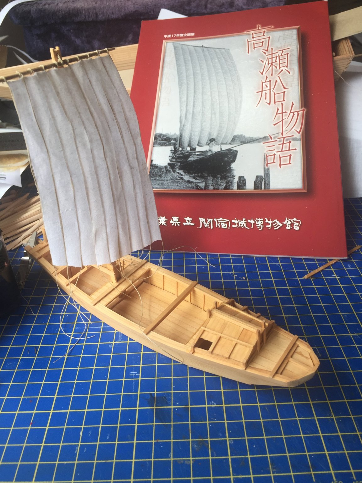
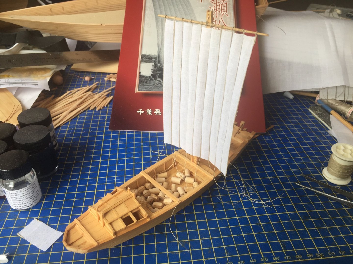
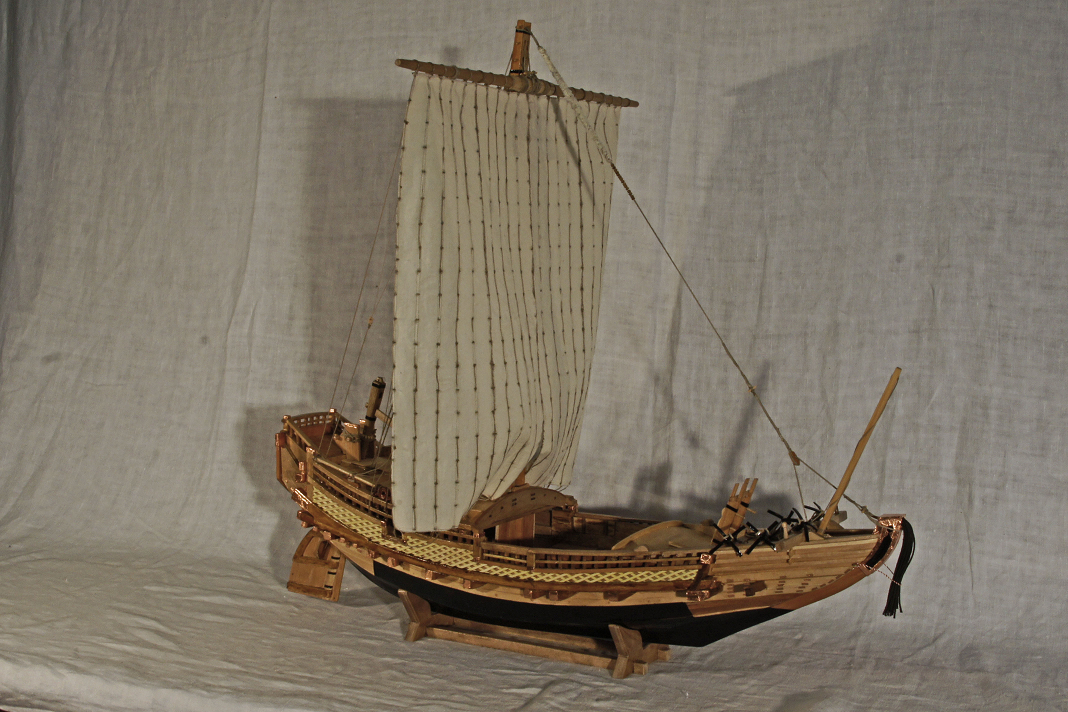
Wasn't really happy with the number of strips having to get cut down to 22. The largest Kitamaebune, which this model represents, had 24. In fact, you could generally tell the cargo capacity of a transport by how many of these panels make up the ship's sail. So, I went back and I prepped and cut a new piece of sail material. But, then I thought I might do better if I experiment a bit with the sail on the Tonegawa cargo boat that I posted about a little while back. It's the same scale, and the sails would have been made the same way, but with only 9 shorter sail panels instead of 24 long panels of the Kitamaebune. One thing about these Japanese sails because of the way the individual panels are sheeted, they have a very distinct, ruffled look. So, I decided to focus on that this time. I basically cut the strips to length, bent them around a small dowel, then glued them together at a slight angle, forming a kind of v-shaped valley between adjacent panels. I also cut the top and bottom edges of each panel to impart a slight curve, to give a sense of the panel hanging down of its own weight. It's not bad, but it doesn't billow the way the real sail should. As you can see below, they hang straight down. At the bottom of the sail, the edges tend to curve forward just a little. I'm working on ways to solve this issue now. But, I do like the way each panel billows just slightly. Next step is for the whole thing to look more natural. The sheets will tie off to a heavy rope that runs across the hull. Note the jumble of simulated rice bales. I'm not sure what to do with these, now that I'm working on a sail. These ships would only need to mount the sail if they are heading up river. Upriver basically means away from the big city toward the farm lands. In that direction, they would not be carrying rice bales. If I want the rice bales, the mast would most likely be lowered as the sail wouldn't be necessary. But, realistically, if I have any rice bales at all, it would probably be full, having loaded up at one location and sailing down to unload them at a dock in old Edo. But, for a representative model, some bales would look nice and so would the sail. So, I'm figuring I'll stack some in the hold in a manner than balances out the load a bit. So, the next step is to try to create a sail that billows a little AND has ruffles. My first and simplest attempt doesn't look too good. I tried treating the sail material again with Terial Magic. The stuff that stiffens the sail material nicely. But, I'm not done with this yet. I got a little more billow out of it, but the sail now needs some touch ups to even out the surface. Behind the model here, you can see one of the books I located on these boats. It's called Takasebune Monagatari or the Takasebune Story. On the cover, you can see a photo showing an example of how the sail looked in operation. Of course, after I get this all figured out, I still need to apply what I learned to the Kitamaebune model. Clare
-
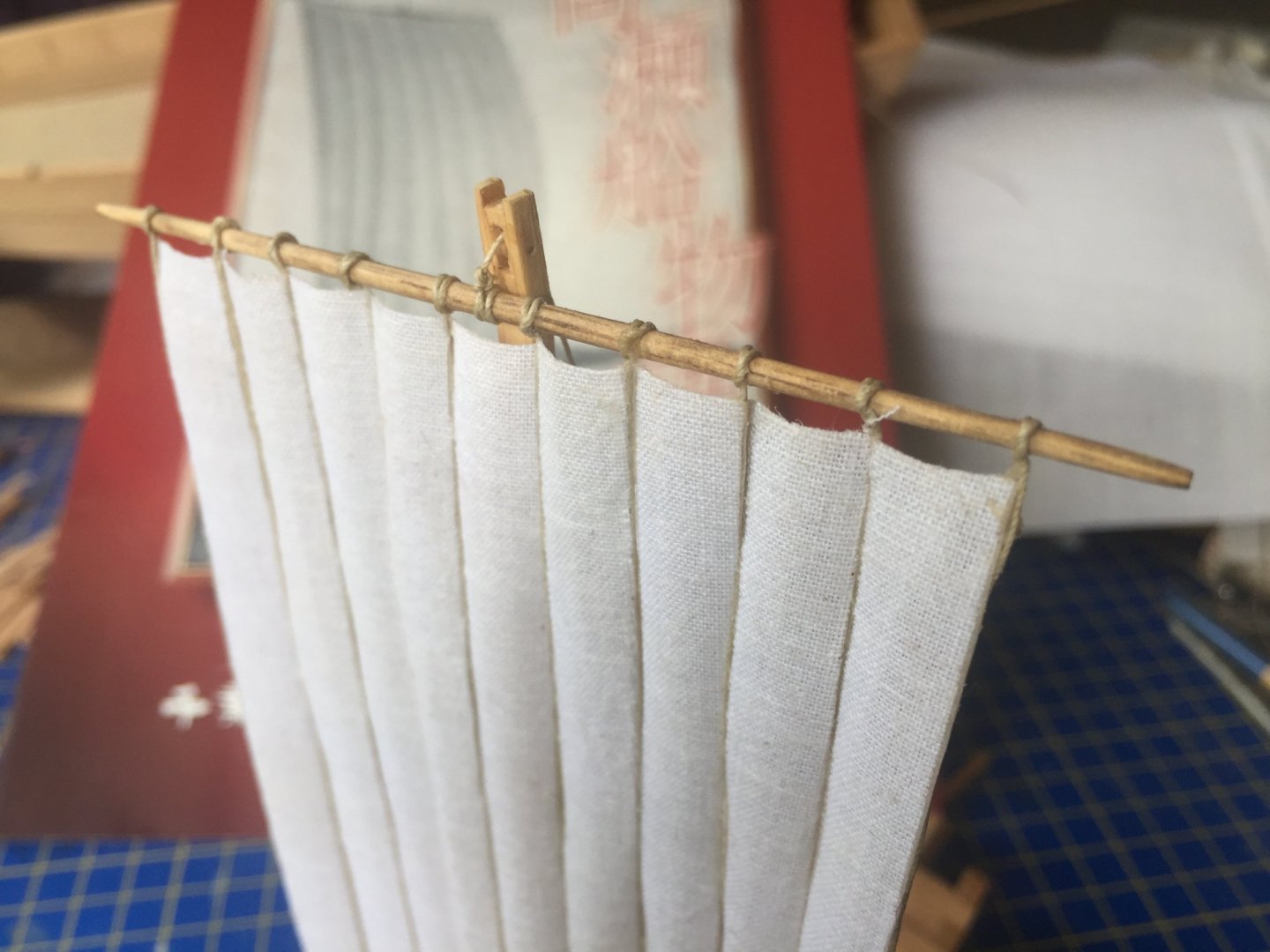
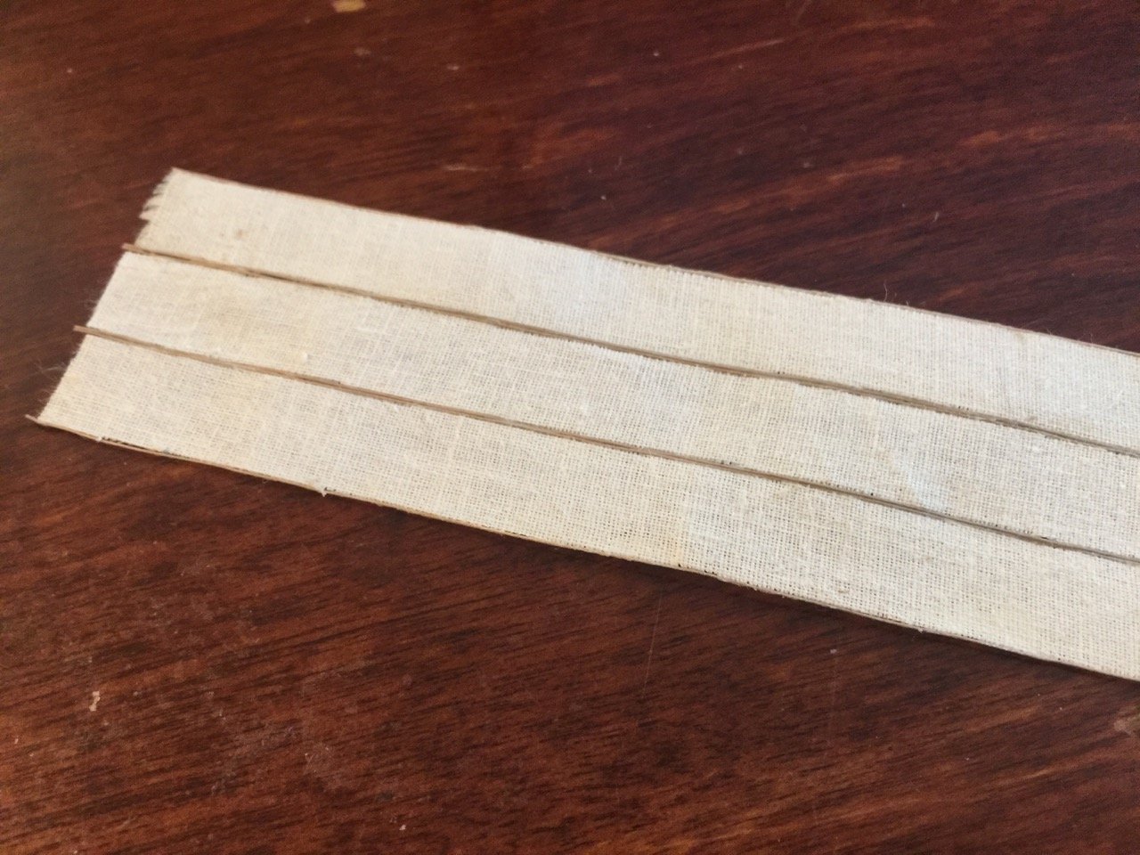
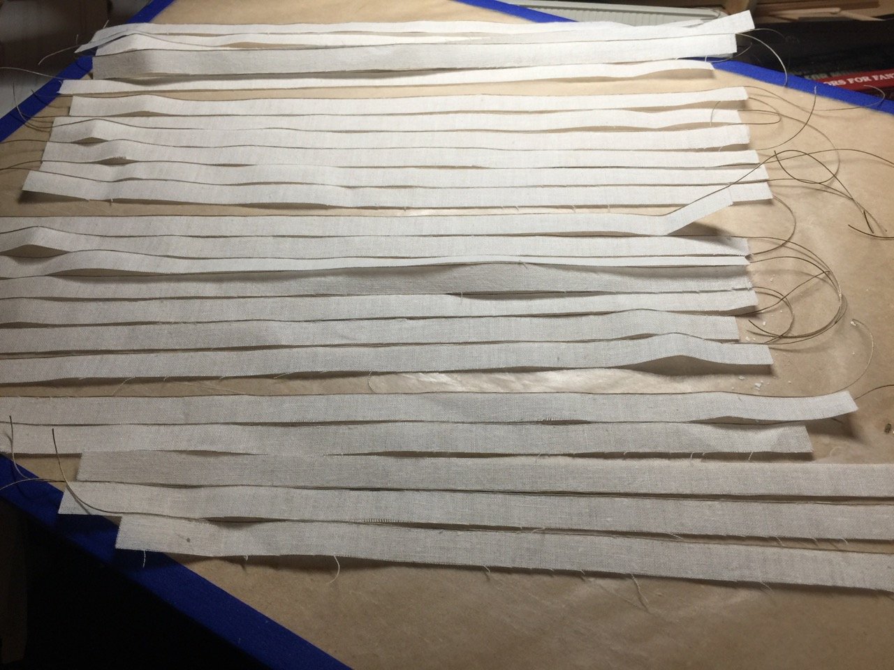
Sail panels are now glued up. I checked the width of the full sail and it looks a little wide, which I figured might happen. Just compound errors in the measure of things added up. But, I preferred to err on the large side rather than small. I'll compensate by cheating slightly, and I'll remove one of the of strips from each of the outer panels. This will put the sail a little on the narrow side. But, when I lace the sails together, I'm going to try to work in a slight gap at the top and bottom, as appears in a number of drawings and on the replica ships. This effectively widens the sail so it should hang nicely from the hogeta, or yardarm. Next step, I'll need to trim the strips so that they line up nicely at the bottom. I managed to glue them up so they line up nicely at the top. But, some strips stretched more than others and the bottoms are a little uneven, as you can see in the first photo. I'll have to be a bit careful, as the strips are glued up with the ropes in between the, but they shouldn't present any real problems. I'm actually considering leaving that short mast at the bow bare-poled. The sail will be really short in order for the bottom end to stay clear of the main stay tackle. I've seen a number of drawings and painting that show the sail, but in a configuration that's physically impossible, showing the sail occupying the same space as the stay tackle... Unless we're talking about shifting into 4th or 5th dimensional space... Anway, it's a little more to think on. In the meantime, I have this sail to complete. Clare


-
Doh! Thanks for the correction Carl. I'm sure the Austrians love that. 🙄
-
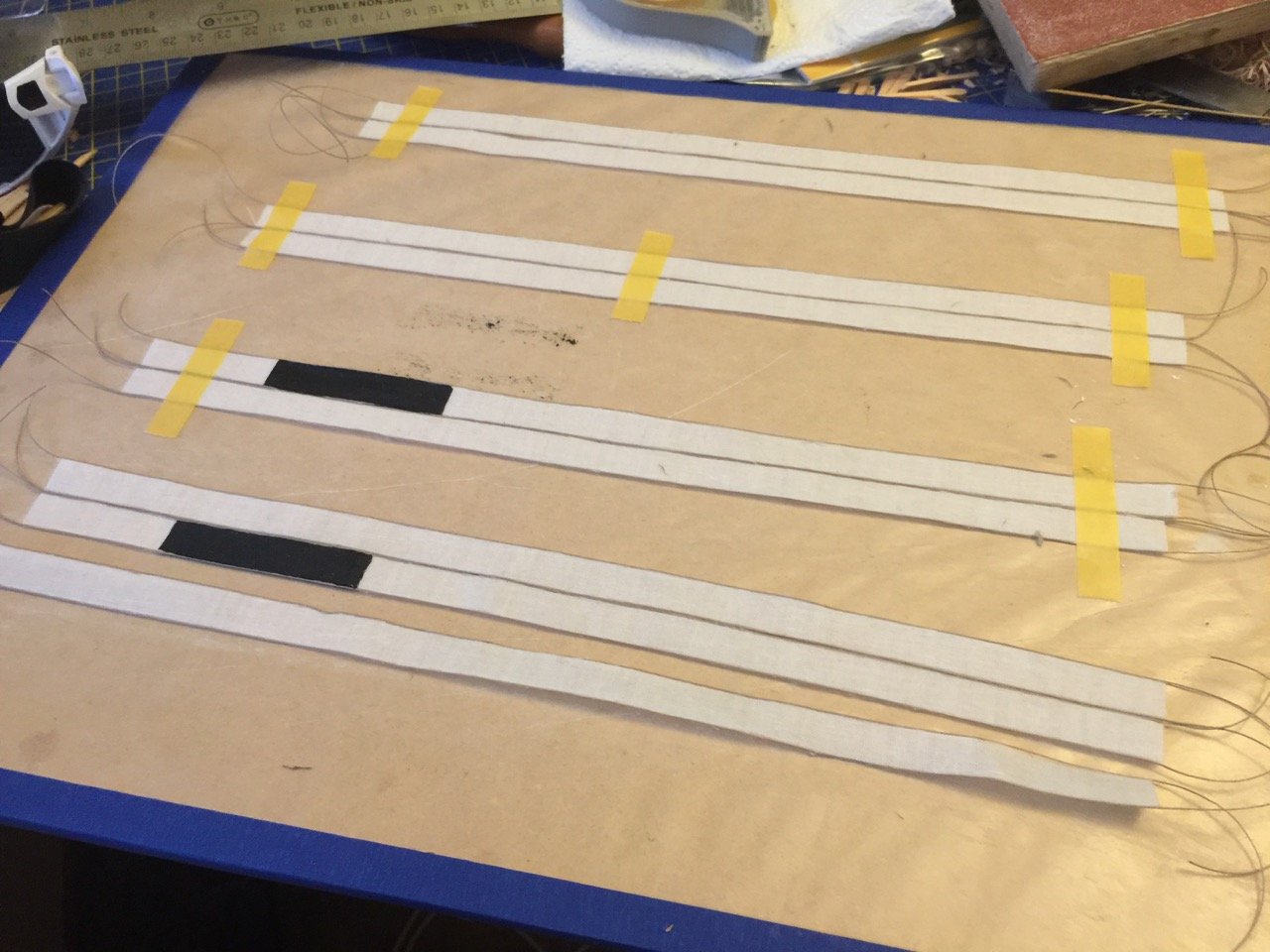
Minor update. I'm moving forward on the sail construction, gluing up the individual strips into four separate panels. Before gluing any of these together, I painted a section of a couple of the strips. These are markings used on the sails of these northern port transports to identify who they belong to. I'm not sure how my sails will look with the markings and may change my mind as to where the markings appear on the sail. But, so far, I'm expecting them to appear as two short rectangles centered high on the sail, separated by two blank strips. I still have time to change the plan as I can rearrange the existing glued up sections a little. I'm going to see if I can take another look at some examples of these markings and make the final call today. In the meantime, you can see how this is progressing... Again, each panel will be made up of six strips, so I'm basically half-way done making the panels. I will also have to decide soon if I will add fake ties of some kind. If I do, it will be a very slow going process. So far, Aleene's Tacky Glue has proven to create a very strong bond. Clare
-
Oh, ran across this thread only today. I'm positive this picture has to date from no earlier than the early 90's. There appears to be a Knox-class frigate in the reserve fleet in the background, judging from the shape of the superstructures. The first decommissioning of one of those was in 1991, I believe. It was a bit confusing because, apparently, Pampanito became a museum ship in the 70's. I'm pretty sure a museum ship wouldn't look that bad. But, further Facebook comments said that she was actually in the movie "Down Periscope" in 1990-something. This must have been a real weathering job then! Unfortunately, being a star in a Hollywood comedy seems a little undignified. But, hey, it probably helped her survive as a museum ship.
-
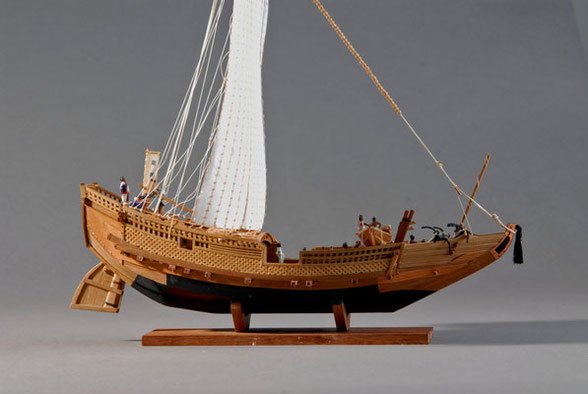
While researching sails, I ran across a great website by a ship modeler in Germany. He scratch built a model of the replica ship Naniwa maru, which is a higakikaisen replica. The website entry is from back in 2012. It looks to me like his model was built at a scale of about 1/50, so it's a nice size. Aw with other builders taking on a scratch build of one of these ships with only limited information, I found his model pretty amazing. http://www.googlehupf.at/shipwright/?page_id=276
-
Just a heads up on some thoughts about the faux stitching... As interesting as this looks on that museum model and in the last photo I posted, it doesn't actually look quite correct, so I'm not quite sure what I'll end up doing. I thought this was a good solution. But, I have a feeling that this is kind of the old model makers solution to a complicated issue. Most models seem to show some kind of horizontal ties like this, but if you look at the replica ships, what's mostly noticeable is lacing. Here's a model by Toshitaka Nakazono of The Rope... And this one by Taketoshi Tanaka, former president of The Rope, and the model used by Woody Joe to develop their Higaki Kaisen kit... Both images are from the english language site of The Rope, in their Photo Gallery of Japanese Sailing Ships and Boats. So, if I do go with the little ties, at least my model will be in good company. And, I guess I can start by making the ties a little shorter, if possible.
-
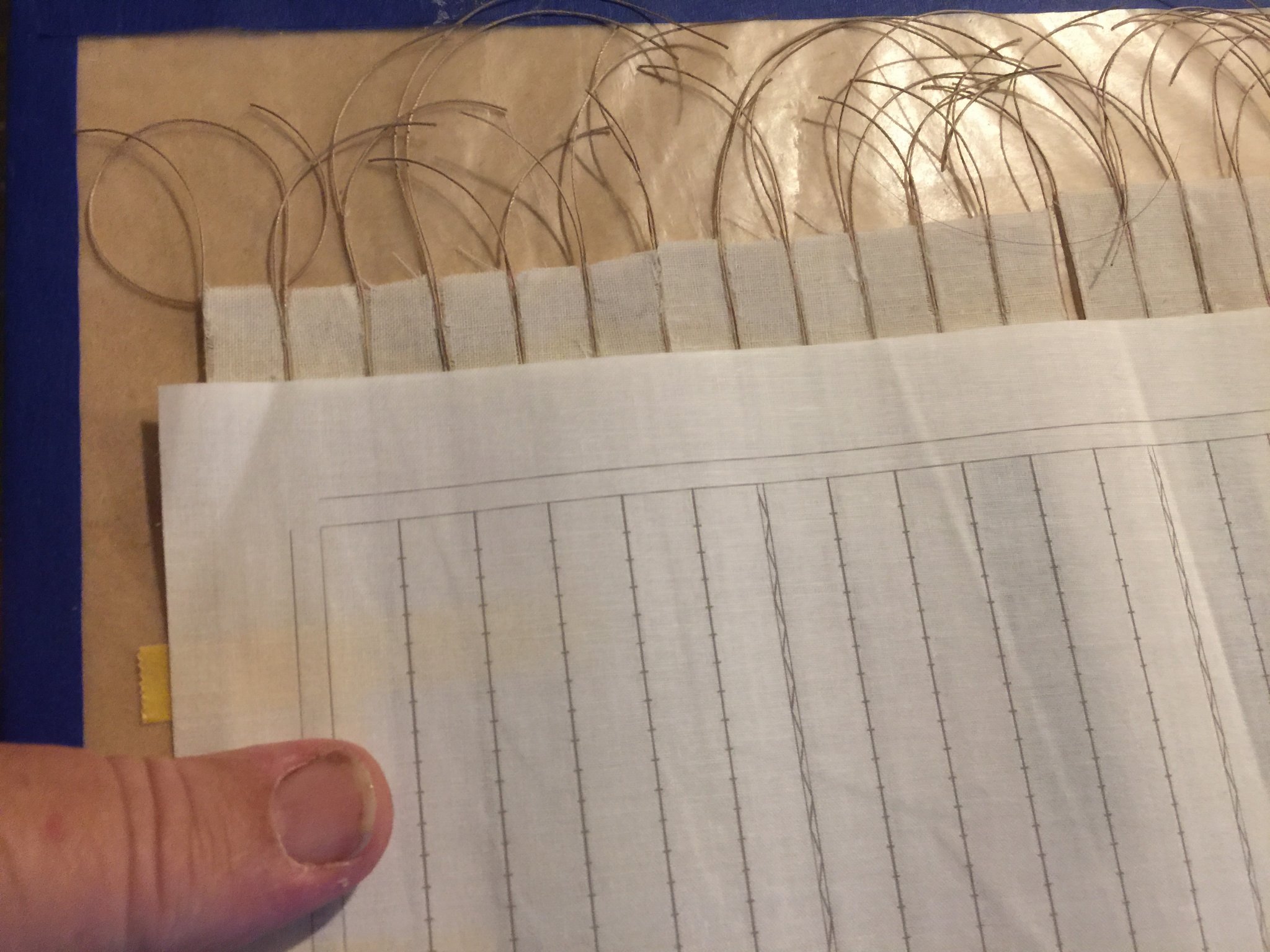
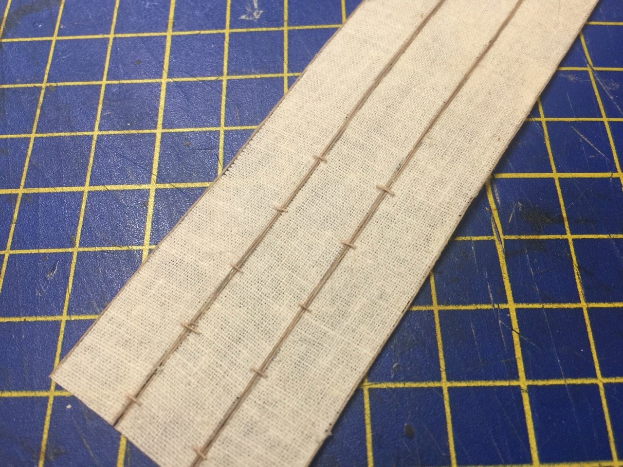
Well, I started experimenting with faux stitching tonight. I began with a length of thread that I'd pre-treated with Aleene's Tacky Glue to stiffen it. When dried, I cut some very tiny 2mm length of it. I'm hoping there's an easier way cut lots of 2mm lengths, possibly by lining up several threads on a piece of double-stick tape or something, so I can cut several pieces in a single pass instead of one at a time. In any case, I then used a pair of fine tweezers and dipped one 2mm piece in some Aleene's, then placed it across the seam between strips of cloth. The result looks like this: I originally started placing them about half that distance apart, but it looked way too busy. These are about 1cm apart. Still probably out of scale for the 1/72 scale model. But, as we all know, it's difficult to make sails correct in scale. I might place them a bit closer together on the actual model. We'll see. Aleenes turns out to be pretty tough. It's hard to remove these things after a very short drying time. You might note the slight gap between the cloth strips near the bottom. That's because I'd taken a scalpel blade and separated the cloth slightly. I think this shows me that it's possible for me to fasten the sails together only with these ties glued on. Of course, the back side needs them also, and they need to be lined up with those on the front side. But, I had little trouble doing this since you can easily see through the cloth when backlit. So, I think I have a plan to move forward now. This strips will be fastened together in groups of 6, and there will be four of these large panels. The next issue will be how to lace the 4 panels together. However, in that case, I'm pretty sure I'm going to go with hand sewing the lacing. You can see in the printed cloth provided by Woody Joe, how the lacing between panels goes. I will probaly also try to show a bit of gap between the panels, particularly the gap that lines up with the mast. Wish me luck!
-
Hi Druxey, we'll see how the sail turns out. I made a sample section of three strips glued up with two threads between each strip. I realize today that it looks VERY flat. The gluing up is strong and convinced me that this should work okay, which is why I'm proceeding with this method. But, I am considering that instead of glueing the strips to each other, perhaps I can tie them together. You can see the horizontal ties in the sail in the last photo of my previous post. The Woody Joe printed sail also shows them, but on their sail, they are more numerous and very small. I'm sure I would use fewer ties, as doing this will end up being really time consuming and tricky at this scale. I'll experiment a little to see if it's even worth doing. If it doesn't add to the appearance, then I might as well just glue up the panes and also glue on lots of tiny thread pieces on both sides of the sail or something.
-
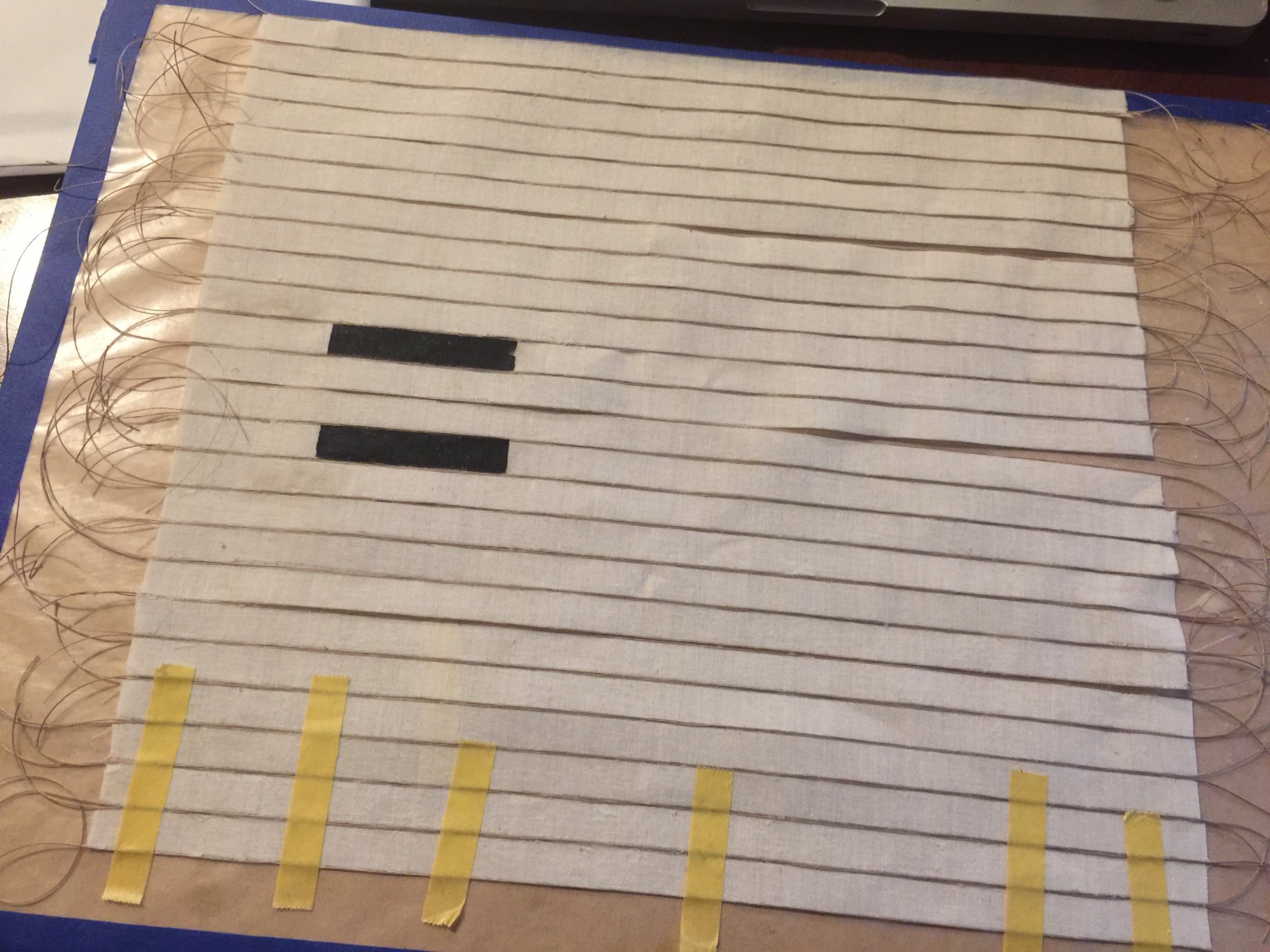
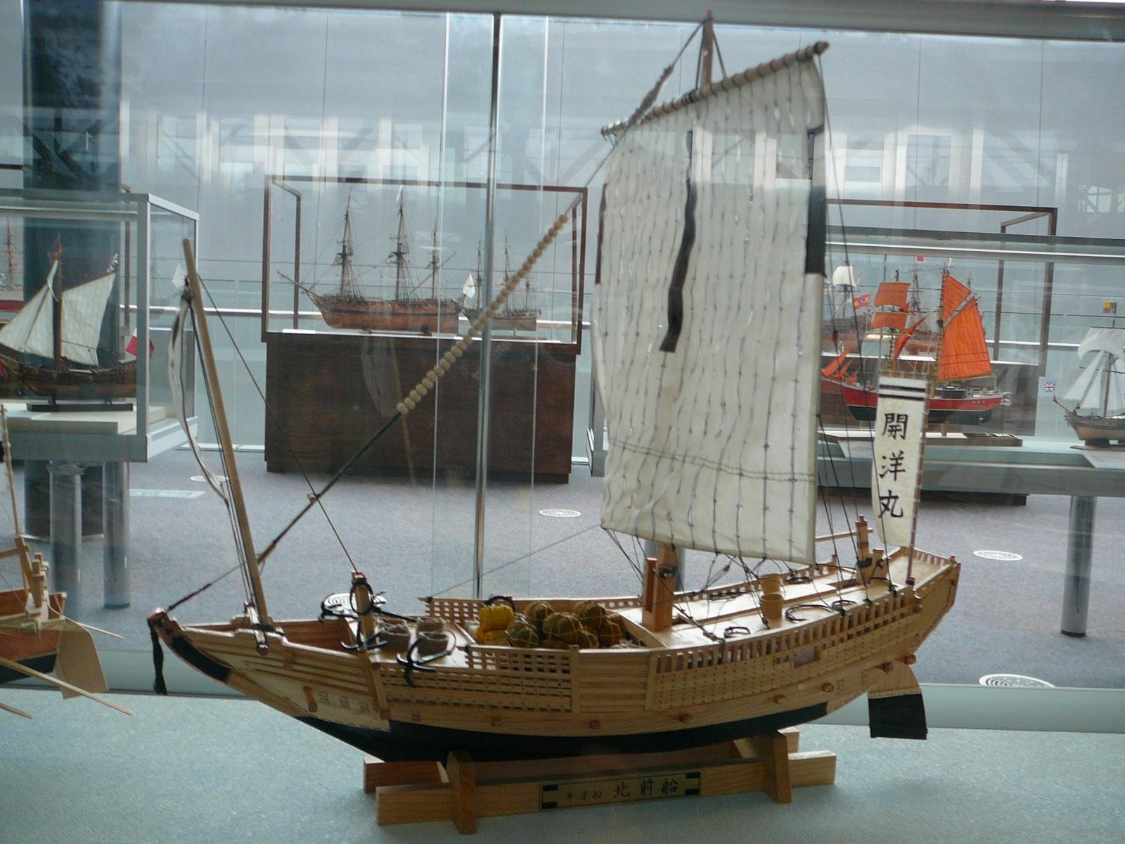
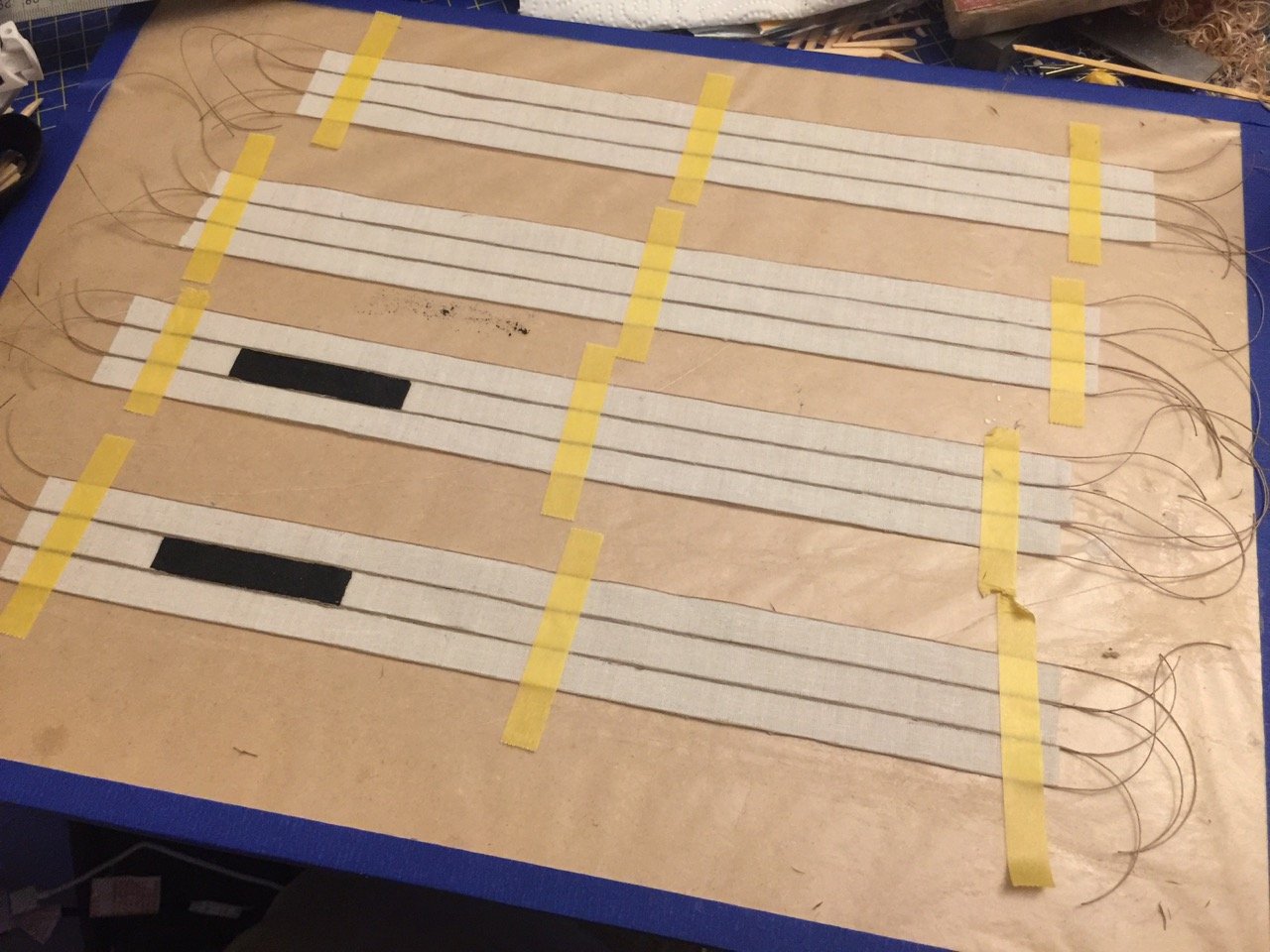
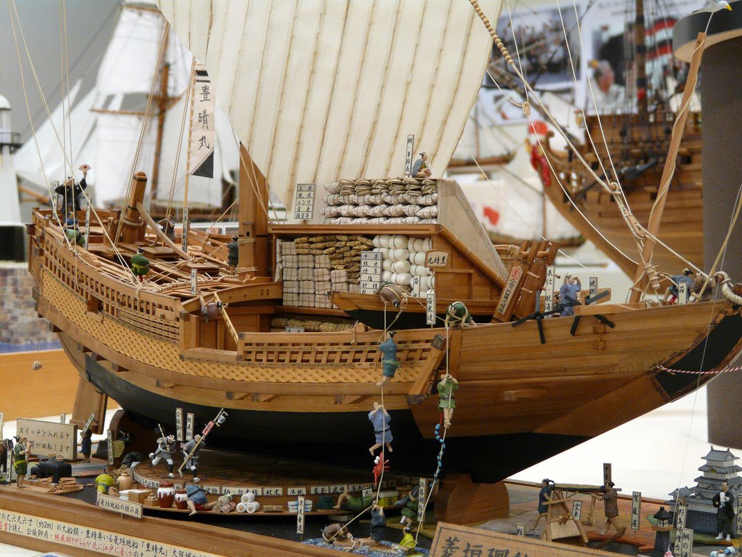
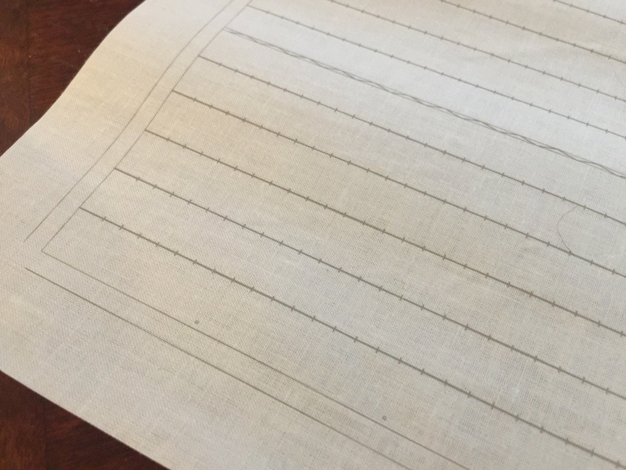
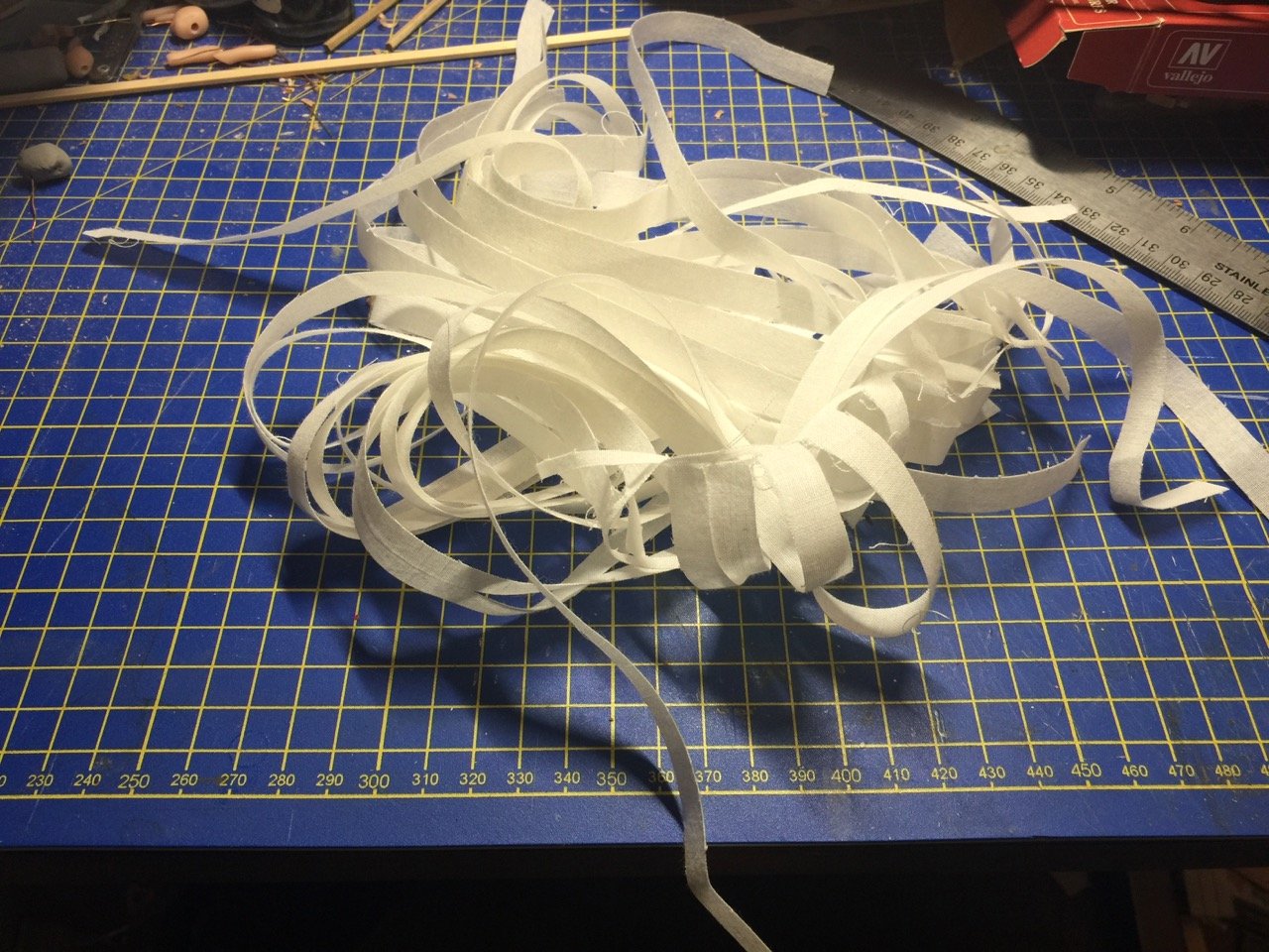
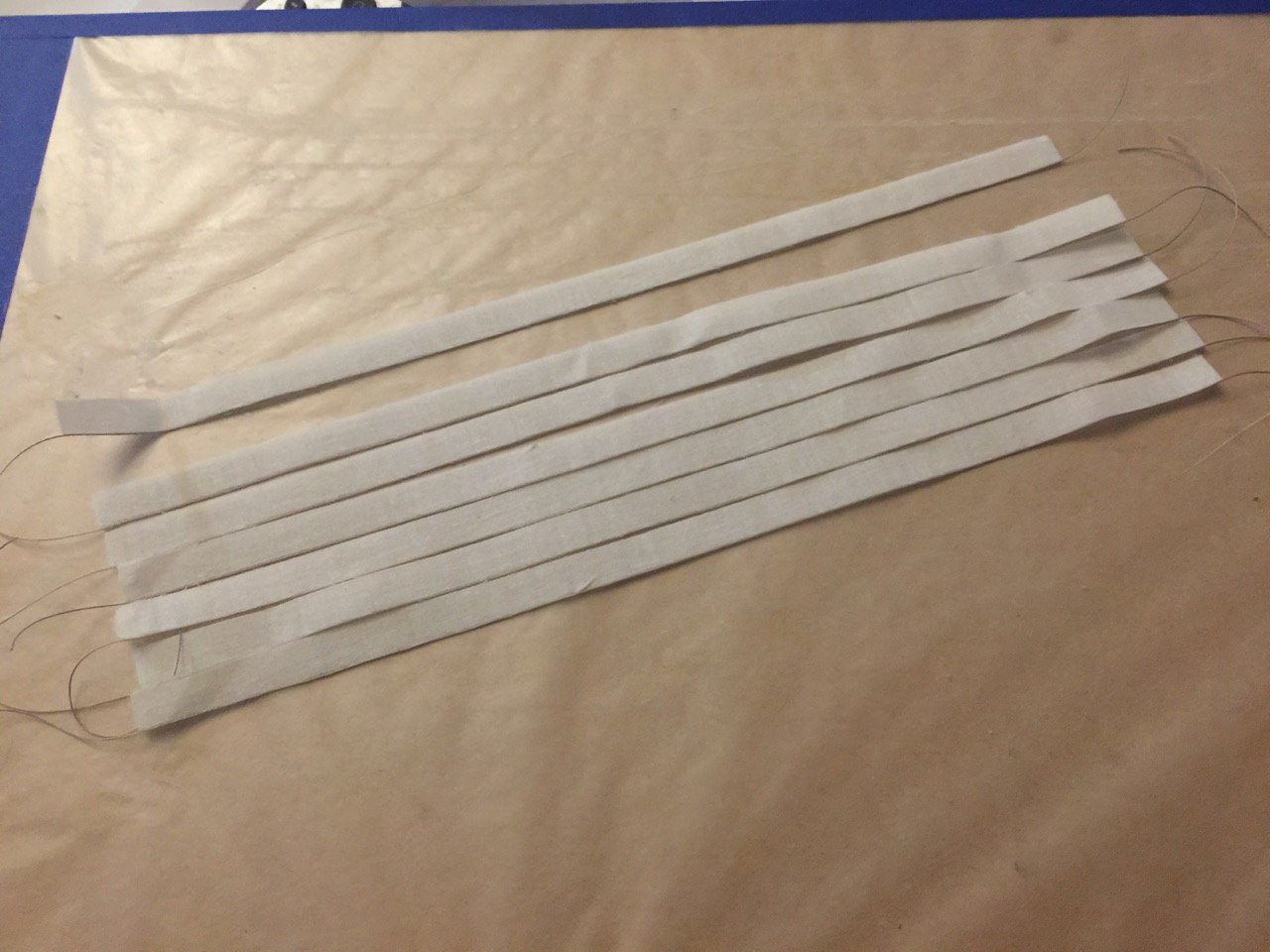
I bet you thought I wasn't going to ever make any more progress on my Kitamaebune project, didn't you? Well, I had decided to move ahead with a sail construction plan I came up with in order to try to mimic the different nature of Japanese sails. Well, I spent a lot of time experimenting and just staring at sail material and at the kit provided sails. Then, I decided to go ahead with what should end up being a pretty labor intensive sail construction. I decided I'm going to assemble the sail from separate panels. I MAY stitch the panels together in some fashion, but at the earliest stage, I'm going to be gluing up the panels. I glue most of my ship model sails now, as it avoids creating out of scale machine stitching. Cutting the sails was simplified greatly by using my Silhouette Cameo 3 machine. I drew up a series of long rectangular panels using the Silhouette Studio software and used it to cut a 12" x 12" piece of cloth. To make sure the cuts were clean, I pre-treated the cloth with Terial Magic, which I believe I talked about in a previous post. This stuff, when dry, makes the cloth somewhat paper-like. The cloth cutting session itself didn't take all that long to draw up and run the cutter. Of course, a lot of cut strips, when peeled off the adhesive faced cutting mat, makes kind of a messy bunch with lots of strands stuck together. I cut the loose threads and then cleaned up each strip, trimming away loose threads. I then applied a thin bead of Aleen's Tacky Glue to one edge and attached a piece of thick, beige thread to one edge. I did this with each strip one at a time. It really didn't take me as long as I thought it would, but I still had to spread the work over a couple nights. The main sail on the Kitamaebune is made up of 24 strips in panels of 6 strips each. I haven't quite decided if I am going to juse use the one piece of thread separate each neighboring strip, or if, like on the real sails, I should use two threads, basically lining each panel with its own piece of thread on each edge. Actually, I lied. I created the strips narrow enough to require me to use two threads between each neighboring panel. So, if I don't use two threads, the completed sails should end up a little too narrow. So, two threads it is. Now, I didn't really think about it before I glued the threads to the sail strips, but the identification markings on the sails should really only appear in the cloth, I think. I don't want the threads painted, so I will have to be careful with the painting. I should also do the painting before I add thread to the second edge of each strip, just to be safe. Now, I haven't decided what identifying pattern I'll use on the sail. I could try to do a little research and see if I can identify one that's specific to a certain ship or trader. Few people would ever "get it", but I guess I'll see if I can look something up this weekend. If nothing else, I'll probably just paint a short segment of a couple sail panels. Below is a photo of a model in a museum in Japan, though I don't recall which one. This is actually one of the old Woody Joe kits before they went with the laser-cut parts. It's a bit more of a "shipmodeler's model" requiring more woodworking and it's also a noticeably larger kit. Not as detailed or as accurate, but it sure looks like a Japanese ship model. There were actually two different kits available of similar large side. Sadly, these kits aren't available anymore, but I did manage to squirrel away one of each when you could still get them. I'm afraid to start one, because then the kit will be gone for good. I've thought about just scratch building a model based on one of the kits, so I can keep the original kit intact. Does that sound silly? Anyway, I still have 5 sail strips left over, so I think I'll prep those too, as I'll need them to make the bow sail.

-
Hi Peter, LOL, the Kitamaebune is acutally a smaller model than the either the Hacchoro or the Yakatabune! 😉 At least, it's smaller in length by about 3" and even an inch or two shorter in height than the Hacchoro. But, the Hacchoro and Yakatabune are both much simpler to build, and better introductions to Woody Joe kit building. The nice thing about the Yakatabune kit is that you have an opportunity to add some details if you want, since it has a little tatami room interior. The Hacchoro looks pretty nice with it's sails set and all the sculling oars. There are things that could be done to detail it too. I've considered building another one that's modified slightly to include details that would show up on a real Hacchoro, or at least on the two remaining replicas. The mini-kits are kind of neat too and they're small enough to base a diorama on one. I've considered having the mini-yakatabune in a diorama of a river or canal lined with cherry blossom trees. Still might do it, as I have one spare kit AND the cherry blossom trees that Woody Joe makes. Water dioramas always look cool to me.
-
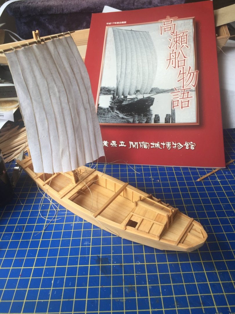
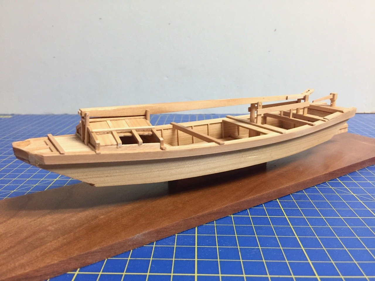
Hi Peter, I went through the small selection of Woody Joe kits of traditional Japanese boats. The Kitamaebune is really the last one, though I do have another Hacchoro and another Higakikaisen kit. For the most part, everything I'm doing is scratch now, including this Takasebune. It was hard to find a drawing with sufficient information that I didn't have to guess on a whole lot. Here's the whole boat, only about 9" long. I was going to make it 1/20 scale so it could be compared with other 1/20 models – a good scale for the medium-sized Japanese boats. But, it was still 36" long, and I'm running out of room here. So, I went with 1/72 scale so it could be compared to the Kitamaebune and later the Higakikaisen model. The model represents a 60-foot (60-shaku, really) boat. These riverboats ranged from around 30 feet to close to 90 feet long. If I recall correctly, a boat this size would typically carry 500 bales of rice.
-
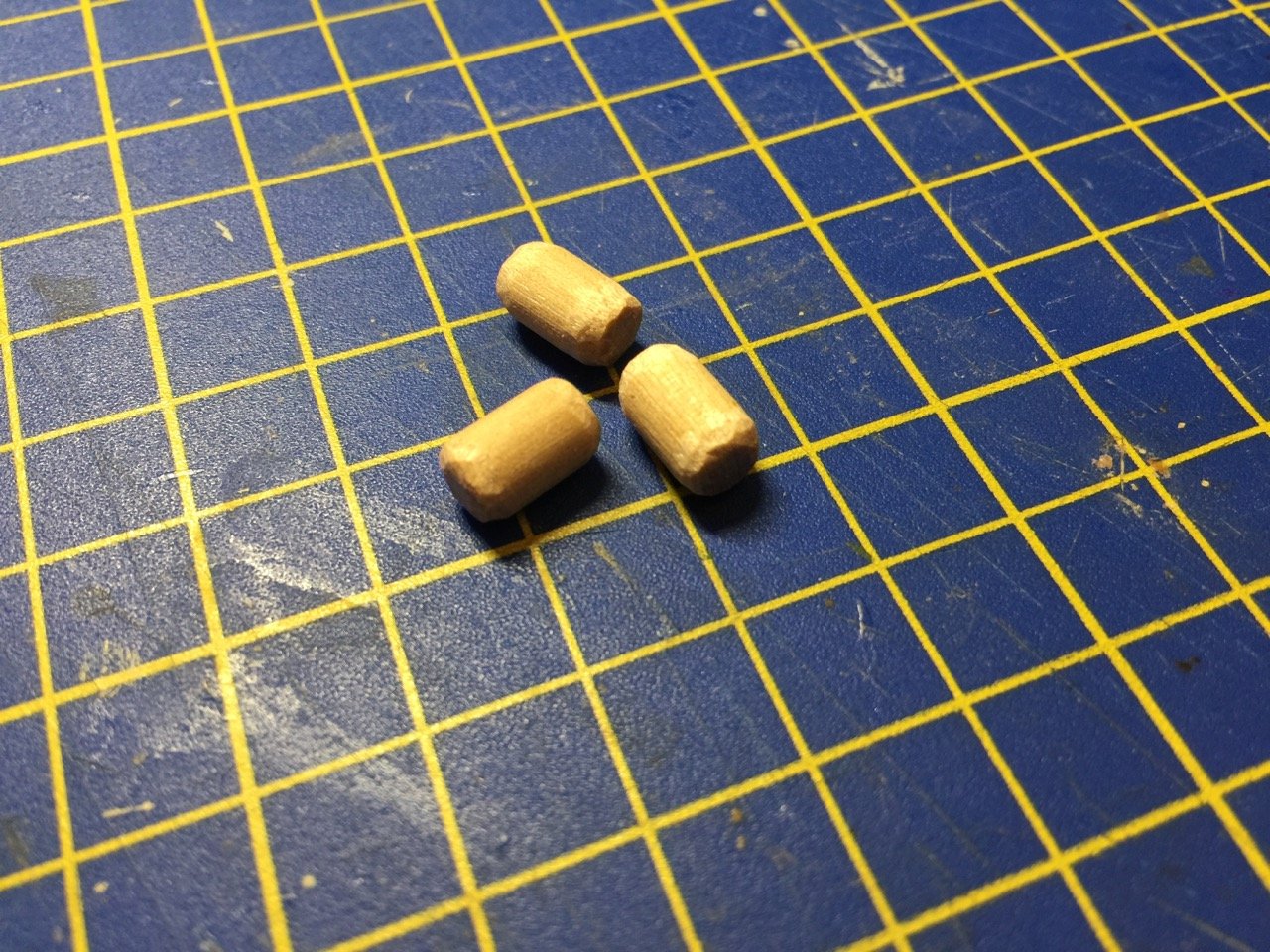
Hi Carl, you know, I considered making them more detailed, but they are already so small and require me to double-wrap 6 pieces of thread around each one of them that I just don't think I care about adding any more detail to them. At any larger scale, I would have to do more, but these are 10mm lengths and each and every one are done individually. I originally planned on making them from polymer clay, but the softening, rolling to get just the right size, cutting, shaping, baking of each one just added a lot more time than cutting off and shaping the wood. If they were clay, I was going to flatten them a bit. Regarding the color, I've seen bales from newely green rice straw, and I've seen bales from older yellow rice straw. They're definitely a gray green here, but it's also a hand tinted photo, popular in Japan in the late 1800s, and the paint itself seems a bit colorful and unnatural to me, so I mostly ignored the colors. Still, you may be right and a more greenish tint could be called for. I'm not so worried about these in 1/72 scale. Actually, I made these after I started trying to make one in 1/20 scale. I shaped it with polymer clay, and I made it a bit of a flattened cylinder, but making it actually look like straw mat has me a bit perplexed. I have some ideas to try. But, to be honest, I'm not very hopeful that it's going to look right. Which is why I suddenly took to making some 1/72 scale cargo!
-
Yes Mark. Yes, it is a consolation... 🙂
-
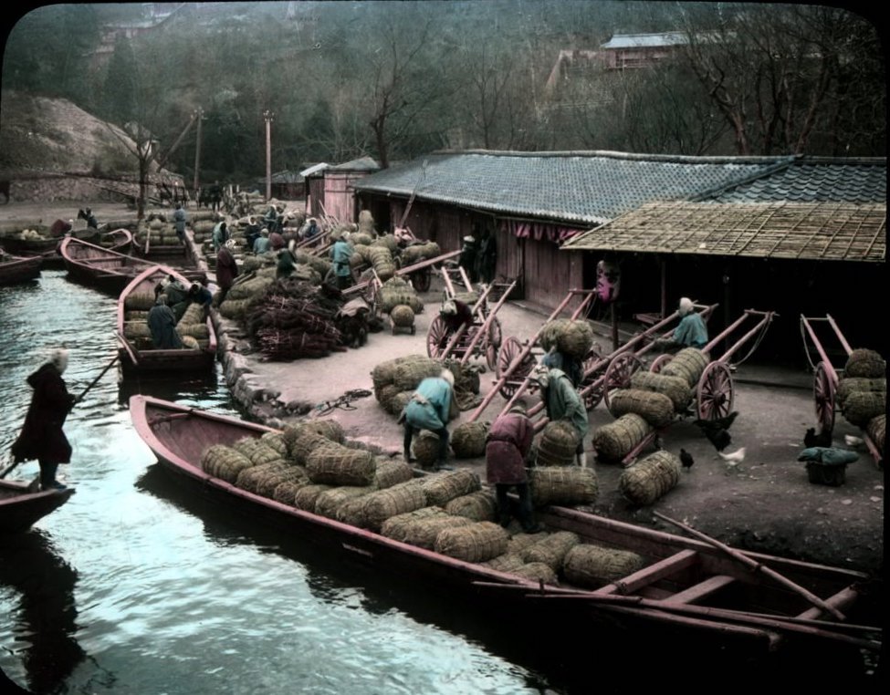
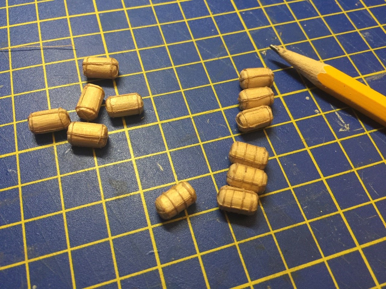
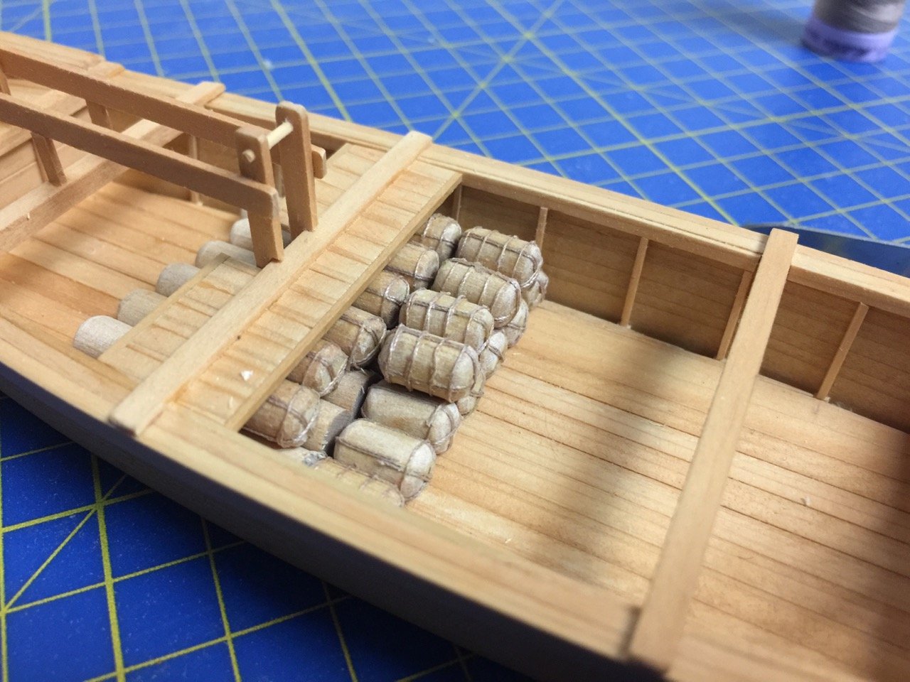
So, here's something I've done since my last posts back in April and May. I started experimenting with the making of cargo. I am absolutely no expert on the kinds of cargo that these ships carried and how it was packaged. But, I think there are three main types in appearance: rice bales, barrels, and packaged goods. Rice bales, called tawara, are the most regular of the cargo in packaging and quantity, since it's the main staple product in Japan. Rice was put into straw mat bags, which were tied up in a pretty specific manner. These were about 1-1/2 feet in diameter and about 2-1/2 feet long. I found this great photo on the Internet that wasn't accompanied by any description, but from the bow planking of these boats, I can identify these as being from the Lake Biwa area. A little digging leads me to determine that these are Sosuibune (so-soo-ee-boo-ney), which were canal boats that carried rice and firewood to Kyōto in the late 1800s. Anyway, I've been making some tiny, 1/72-scale tawara. I don't know if I'll add them to this model, but I think they would work. They're just so small and time consuming to make as many as I would need. I ended up making them initiall for this project that I whipped out in a couple weeks. It's a Tonegawa Takasebune, a river cargo transport that brought shipments of rice from the farms upriver from Edo. They were famous boats and numerous. One of the noticeable features is a small cabin near the bow. These models call for a large number of these tiny things to be made. But, if you look closely, you might be able to see how I can cheat a little. The bags that are completely hidden can just be plain dowel, the ones on the bottom, can mostly just be detailed on the visible end, the ones on top are the only ones that really need the full detailing. The same would be true for any I decide to mount on the kitamaebune. They take time to make and so many are needed...
-
I'm just getting back to the Kitamaebune model... yikes, 4 months later! I'm really happy with this model, though it some rough spots early on. At this stage, I feel it's a very accurate model of a 19th century trade ship. I'm going to try going with a kind of complicated and possibly fragile sail construction, but I think it should look very good... right up until it falls apart. More on this later. I just wanted to share this link that I learned about this past week that might be particularly beneficial to those who are building, or are interested in building, one of the Japanese coastal transport kits from Woody Joe. There is a book published by the Tokyo Maritime Science Museum on Higakikaisen and Tarukaisen (barrel carrying transports). It's a small format book that I think cost me only about $10 or so. But, of course, if you want to buy a copy, you pretty much have to be in Japan to do it. Fortunately, what I found was that you can download a pdf copy of this book for free from the Nippon Foundation website (Japan Foundation). Here's a link to the download page (in Japanese): http://fields.canpan.info/report/detail/4963 And, to make life easier for those of us who can not read Japanese (all of us, maybe?), here's the direct link for the download: http://fields.canpan.info/report/download?id=3233 I hope more people will build one of the Woody Joe coastal transport kits, though I know now is a terrible time to try to get one, since normal mail service from Japan to the US is non-existant right now. And, while DHL shipping is available, it's SUPER expensive. One thing to note is that there is a Japanese shipping service that's now available in the US called Yamato Transport. Our favorite Japanese online shop Zootoyz.jp is able to use this to ship the mini-kits to the US, and he can fit 2 or 3 of them in a package, that should cost $20 to $40 to ship, and it shouldn't take more than a couple weeks to get, if that. If you just contact Zootoyz about what you want, he can tell you what they can do.
.jpg.04ae02eaaa3a150e3c68a28c92a6ce4a.jpg)
2.jpg.029e030d9666697448f5833d590b0d8f.jpg)
-
Very nice! I'm not sure why, but I've discovered that I really like these Spanish warships. Maybe it's the cool names. My favorite name of these OcCre kits is the Neustra Señiora de las Mercedes – It's just so enjoyable to say. The San Ildefonso is a nice looking ship, and the kit looks nice too. Sorry to hear about the delays, waiting for the additional planks. I know that things like this do happen occasionally. Clare
-
No. it's so he can identify himself in the mirror.
-
Hi Jeff, The Amati kit has gone through various changes, but I'm not aware of it being out of production. I do a lot of work with the Amati importer Ages of Sail, and it's still being sold, though now with tools. I think the same kit used to come with a resin hull, and that's no longer available, if that's what you mean. As for blocks, Amati just uses standard Amati wooden blocks. Might not be very accurate for a 1934 boat, but wood is pretty. The kit should come with a parts list in the instructions that identifies the needed blocks. If you want more accuracy, I think the metal blocks that BlueJacket sells might be more correct, though they have to be painted. If you can't find the parts list, I can see if someone in the Ages of Sail shop can dig up the info.
-
Always feel free to ask questions! Asking them inside a build log is perfectly fine, particularly if you have people following it. Occasionally, you may need to go outside of your build log, as sometimes, it's hard to find answer from just those who follow your build. Good luck with your first build!
-
Beautiful work, Chris! I think this puts you, Chuck, and myself roughly at the same stage. Only, I've had a lot of unrelated issue get in the way that's pretty much halted my progress for the past month or more. Hope to get some progress going again, so I don't fall too far behind you guys!
- 179 replies
-
- 3
-

-
- shipyard
- wütender hund
- (and 1 more)