

catopower
-
Posts
1,900 -
Joined
-
Last visited
Content Type
Profiles
Forums
Gallery
Events
Everything posted by catopower
-
 The lateen rig is not a subject that one can find a large amount of information on when it comes to ship modeling. In most cases, I see lateen yards are located inboard of the shrouds. This makes sense to me, though I then am always left to wonder how one tacks or jibs such a rigged vessel. Now, I've been looking at early American gunboats from the War of Independence as well as those of the Jeffersonian era and War of 1812, etc. There are a lot of lateen rigs there. I'm interested in the Galley Washington, for which there is a nice set of plans from the NRG, plus the monograph. However, one thing that's always bothered me about these plans is that they lack much detail when it comes to rigging. Still, the monograph goes as far as saying that the lateen yard goes outboard of the shrouds. Is it true that some lateen rigs are done this way? It seems odd to me in that with sails up, there are no parrals to hold the yard against the mast, so all the force of wind is taken only by the halliard. What's worse is that the halliard is being pulled sideways from the pulley in the mast top, so it would be constantly be chafing there. It would also be very difficult to haul the yard up in the wind, as the pulley would be next to useless. Now, I get that the main focus is a POF build of the hull of the ship and not with the rig. In fact, if you mount sails, the model plans don't seem to make any allowances for the belaying of sail handling lines, such as the brails or sheets (if that's what they're called on the lateen sail). So, I'm hoping someone can shed some light for me on the lateen rig. Or maybe just on the Galley Washington plans?
- 14 replies
-
- 3
-

-
- lateen rig
- washington galley
- (and 1 more)
-
Proud owner of a Dremmel drill stand
catopower replied to DaveBaxt's topic in Modeling tools and Workshop Equipment
Also, not everyone is blessed with the space to keep and operate bench tools. The Dremels are very versatile and don't take up lots of space. The Vanda-Lay products mentioned earlier are ideal for those with a small workspace. I used to use the AcraMill Plus with a Dremel as a drill, mill, mini table saw, and more. But, yes, if you have the space a small bench-top drill press is easier for a lot of things. Plus, you don't have to spend the time reconfiguring it, like you do with Dremel attachments. -
kit review Sir Winston Churchill - Woody Joe
catopower replied to catopower's topic in REVIEWS: Model kits
Hi Welsh John, that's is really helpful. I'll have to look at the booms more closely, but your description makes sense. Thank you for the info! Clare -
I think it's likely that it is Butapren, a kind of super strong rubber cement. I've seen it sold on a Polish paper modeler shop site that has some connection to Shipyard. It's commonly sold in tube form, but I think it can be purchased by the can. But, I've only seen it with Polish label, so you'd probably have to find some local equivalent. ]


-
I agree with Chris, it's the Half Moon or Halve Maen. But, only the Corel kit has 8 gun ports. Most other kits, particularly the more recent ones, and the replicas show the ship pierced for 4 guns, 2 on each side. Just like this model.
-
Hi Sam, I was interested in the N.S. del Pilar kit, but I initially got turned off because of the oddness of the poop deck in the kit. The edge of the upper-most deck is oddly exposed, extending out past the bulwarks. This didn't seem right to me. But, hen, I ran across some plans of the ship and saw photos of older models of the ship, and they all show this rather unusual feature. Readin a little about her history, and about how she was rebuilt in 1750, I'm guessing that the poop deck might have been extended to increase the number of cabins or cabin space on the quarterdeck below. I any case, I now find her a very interesting ship, and am enjoying following your build.
-
It's interesting that you received it in six boxes. They have the kit in a single box at Ages of Sail. You somehow received the kit from their supply of "Packs" or part kits, but I think the instructions are the same as the ones in the full kit. This is the only kit I'm aware of where OcCre actually broke down the instructions into six stages to match the part kits. I have the Montañes as a part kit and you just build until you don't have enough pieces to go on, which now that I think about it, is going to be pretty weird. Your NS del Pilar is looking great!
-
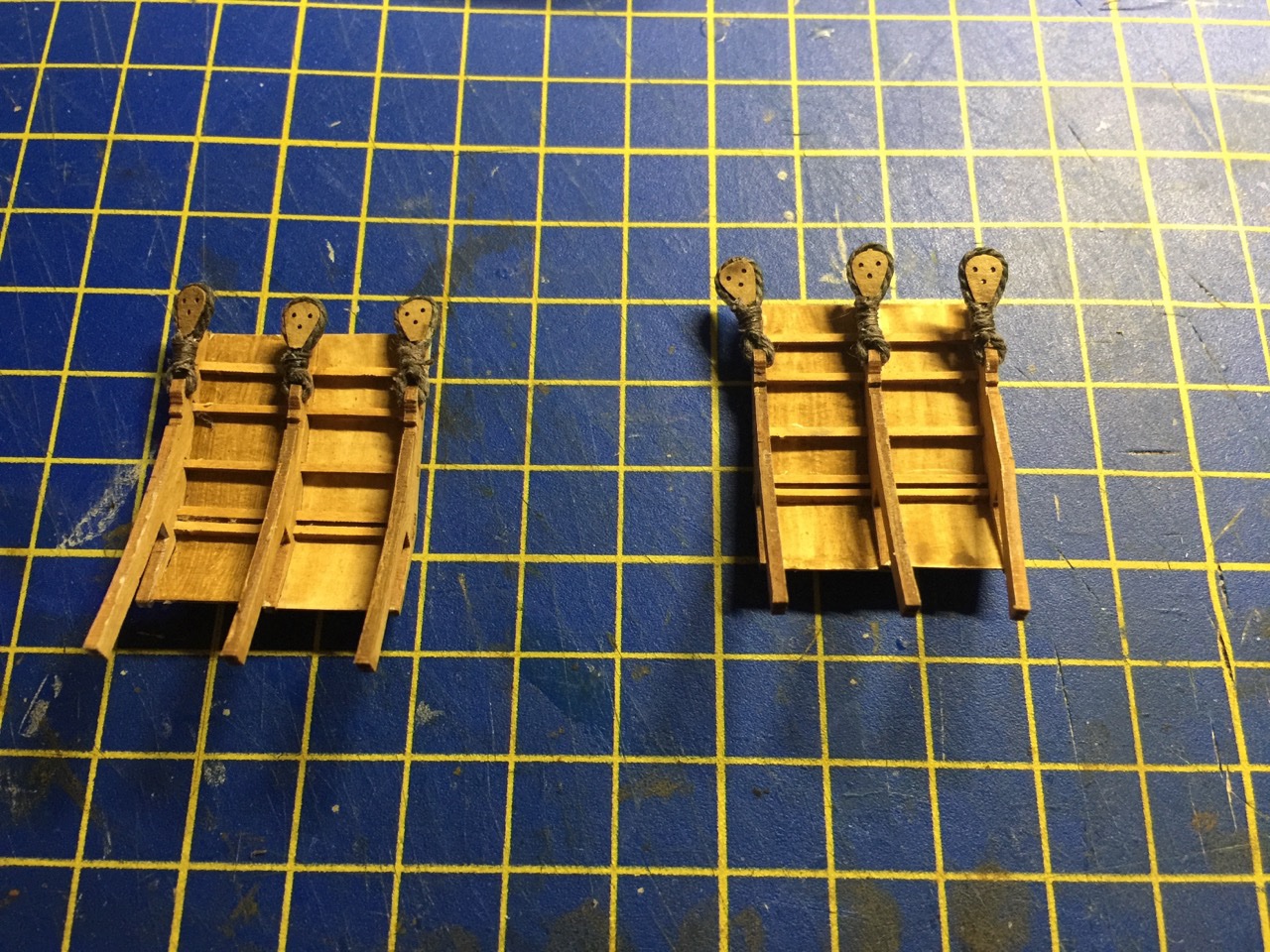
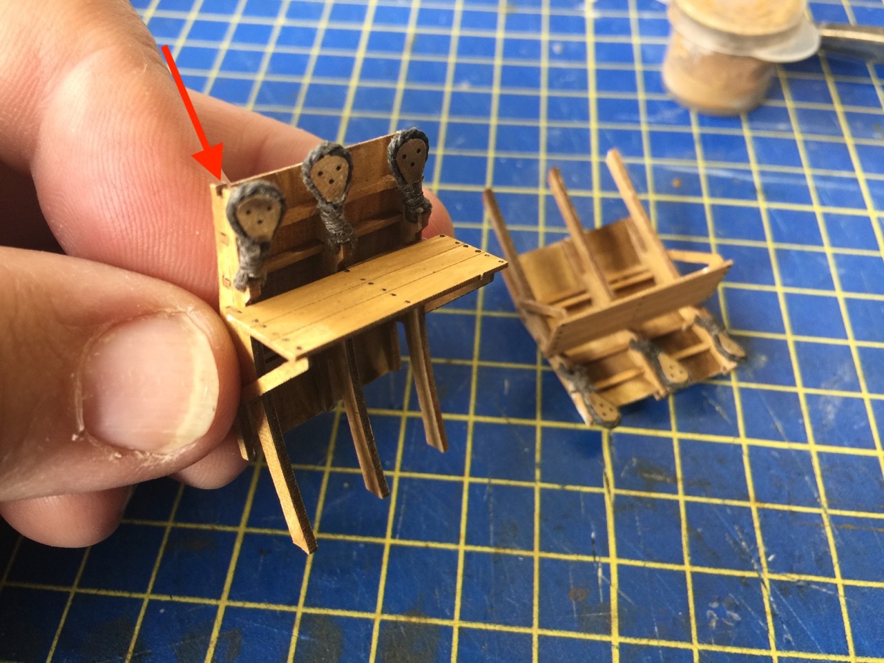
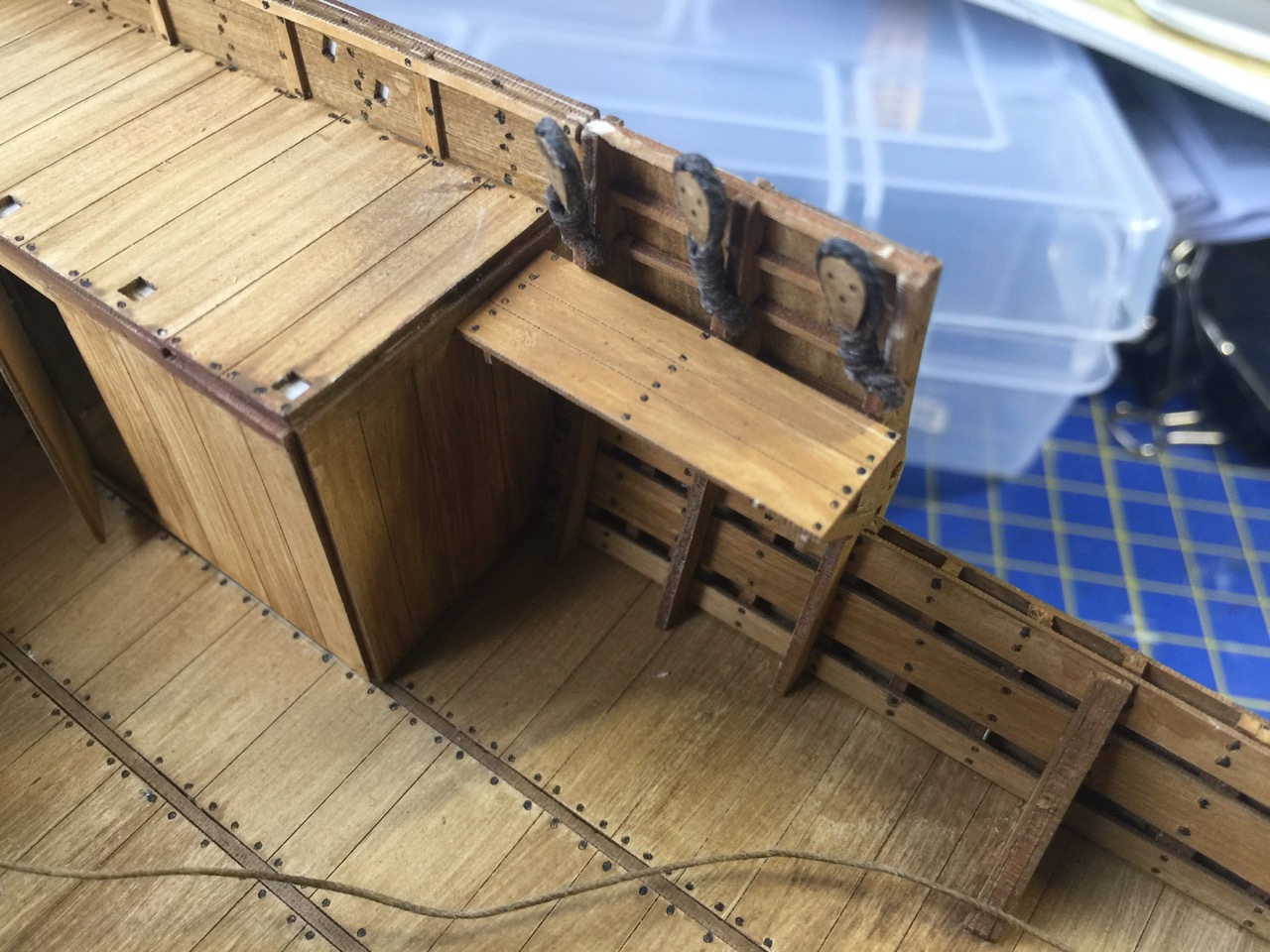
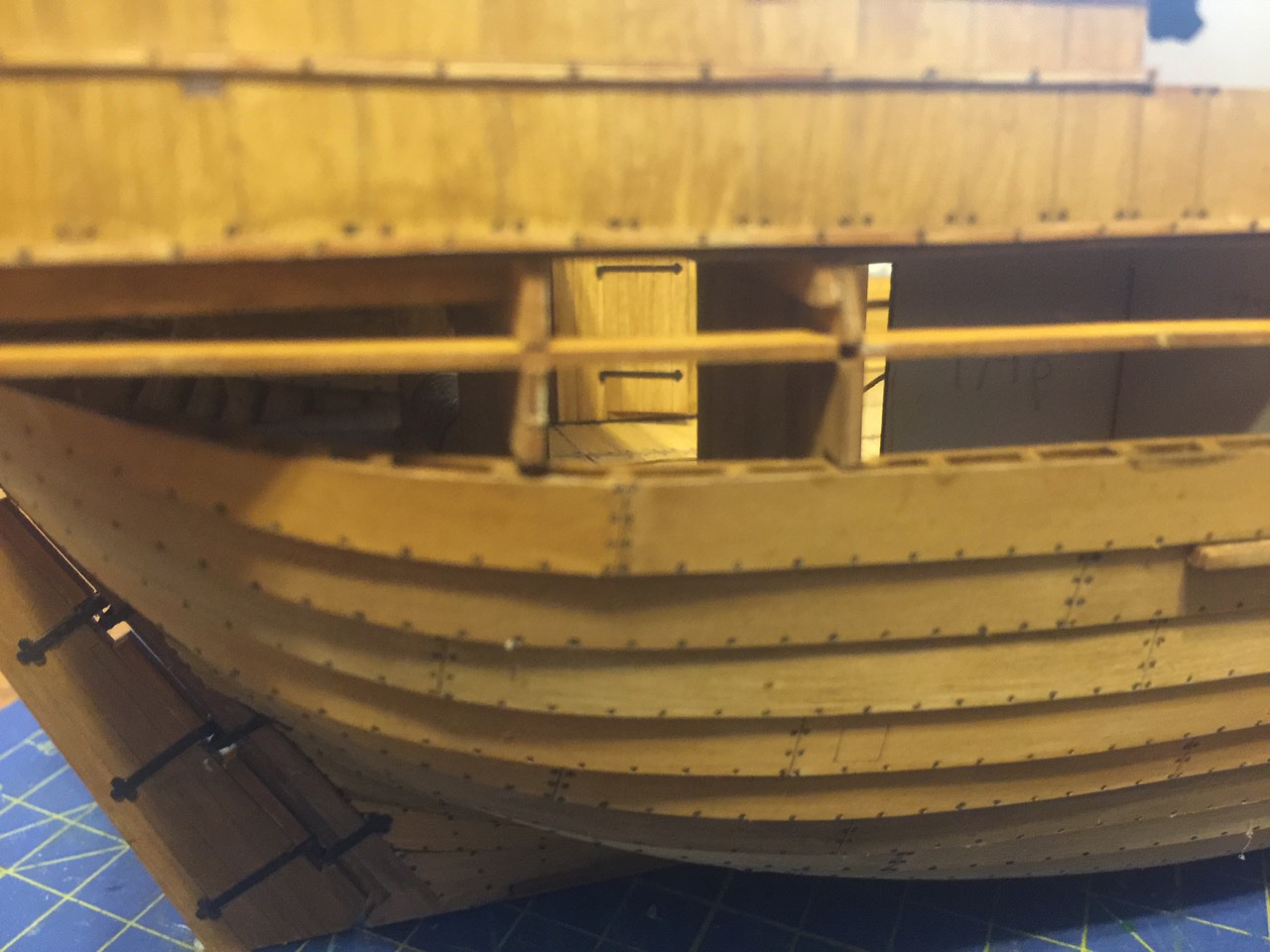
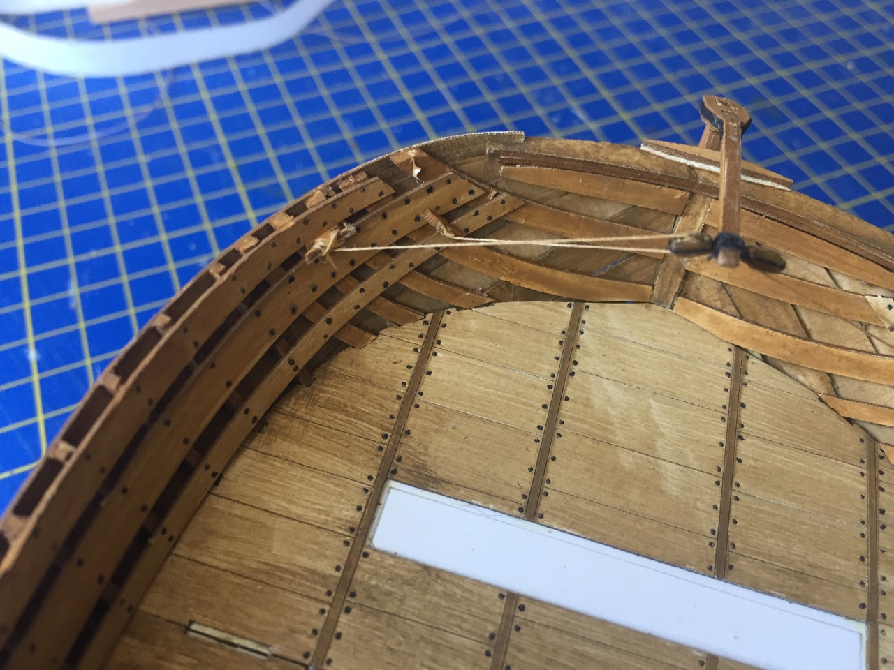
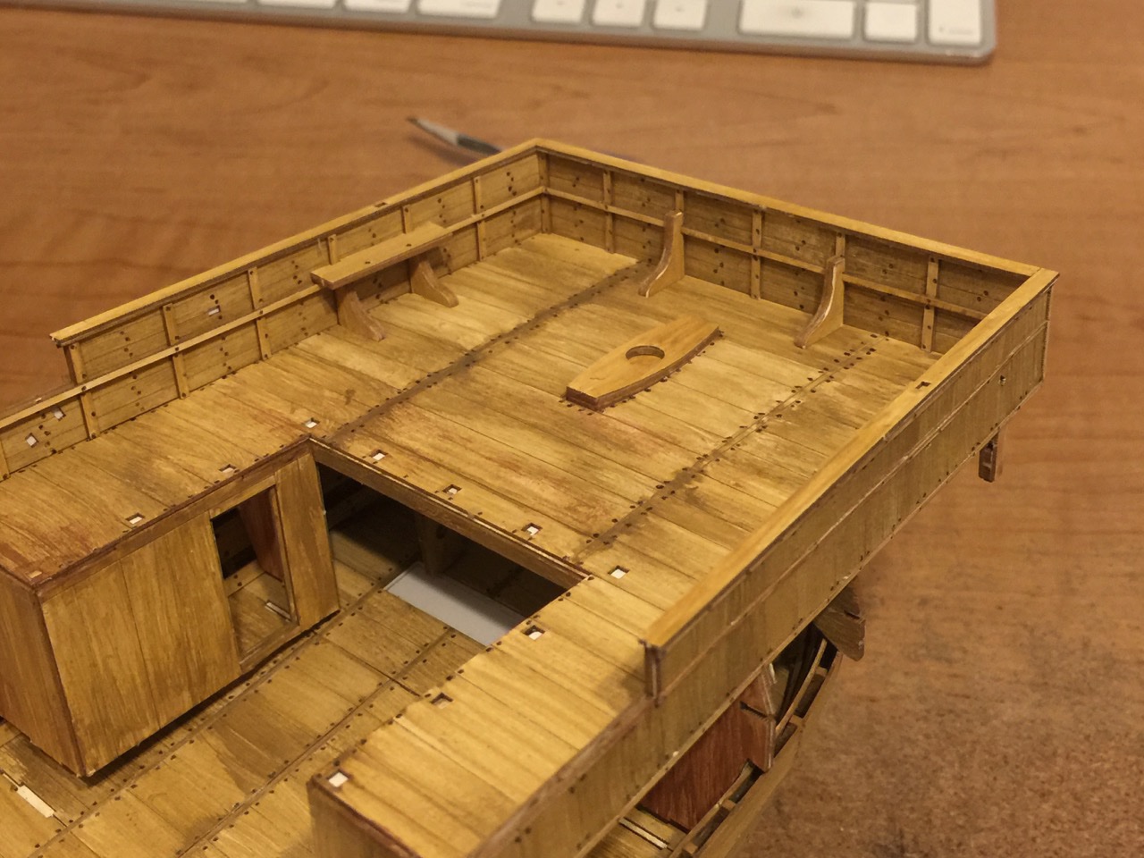
Finally got around to mounting the deadeyes to those hull structures that I have no name for. I have to admit that I've been dragging my feet on this step, as "rigging" has kind of fallen out of favor with me. Not good for a modeler of sailing ship! Probably more of a phase. I tend to get into whatever type of work I happen to be doing and don't take well to shifting gears these days. And, I guess I particularly like hull construction, deck planking, and probably research most of all. But, it was time to get back to the Cog after a general break from most everything fun these past couple months. So, deadeyes now in place... As I was working with these, I realized there were notches at the top of these structures (see arrow in the photo below)... was something missing? I looked at the instructions, which didn't show me to add stringers here, like the others below, but in a latter photo in the instructions, the pieces magically appeared! I managed to add those pieces, and of course the little deck and the supports you see above. Then, looking forward, I noticed how these assemblies were fit into place, and it suddenly became apparently, that I had no idea if these little decks would fit into place correctly. Looking closely at the instruction photos, it looked like I might have them wrong. I ended cutting these little decks off, deciding it was much smarter to mount them AFTER the assemblies were fixed in place. NOW, it's safe to add those decks so that they fit right up against that deck cabin bulkhead. Well, anyway, it's progress!
- 175 replies
-
- 7
-
-
- hanse kogge
- shipyard
- (and 1 more)
-
Hi Christos, your build is coming along beautifully! The Royal Caroline kit has alway been one of those builds on my wish list. As for your paint or no paint question, first off, I have to agree with the comments that it's totally up to you. That said, I will add the comment that whatever you do, some people will always think it would look better the "other way". When I get around to building this kit, I personally really like the look of the model in the box art, which shows a white bottom. However, the wood showing on that model is very light in color. My one concern is that if the wood is too dark, then to my eye the contrast might be too stark. Of course, were I actually building the model, if the planking looked too fantastic, I might opt for no paint, just because I might hate covering it up. How's that for a not-really-an-answer answer? 😀
-
This kit is indeed plank-on-bulkhead. And, while some listings say it's a brand new kit, I can tell you that it's been out for years. But, I don't know how many. Never built it, but I have opened up the box and looked through the plans and such. Very nice looking kit. This is one of those kits I've eyed for a long time. I like Corel kits in general and this one is a large scale, so it would make it easy to detail. Ages of Sail has it in stock, which is where I've seen it.
-
Hi Peter, Looks to me like OcCre simply screwed up in the amount of 0.5mm limewood strips they gave you. According to your parts list, there are supposed to be 7 strips. I actually have this kit as well. It has one bundle with all the wood strips in it. I have 11 of those .5mm limewood strips. So, I got my 7, plus 4 extras. You got 7, plus 28 extras. Oops! Better to get too many than too few... 😀 Clare
-
I am glad to see your progress on the model. It is a lot of work planing such a large hull, isn't it? The large OcCre models are particularly challenging, as they feature only a single layer of planking of the hull. So, getting a nice shape and dealing with gaps is much more difficult to do. Also, the planking material that OcCre provides for the lower part of the hull, is it sapelli? That is harder to bend than the Lime wood they usually provide for the first layer of planking of their smaller kits. Nice work! Clare
-
If it's any help, Pear wood takes dyes very well. I've found it works better for me than other woods. I used Fiebing's black leather dye. Soaks it right up and it is blacker than black. You do have to rub it down after it's dry to take off any excess, and that leaves it with a slight, rather nice sheen. Pear wood also works VERY nicely.
-
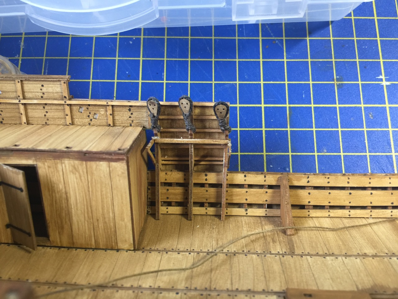
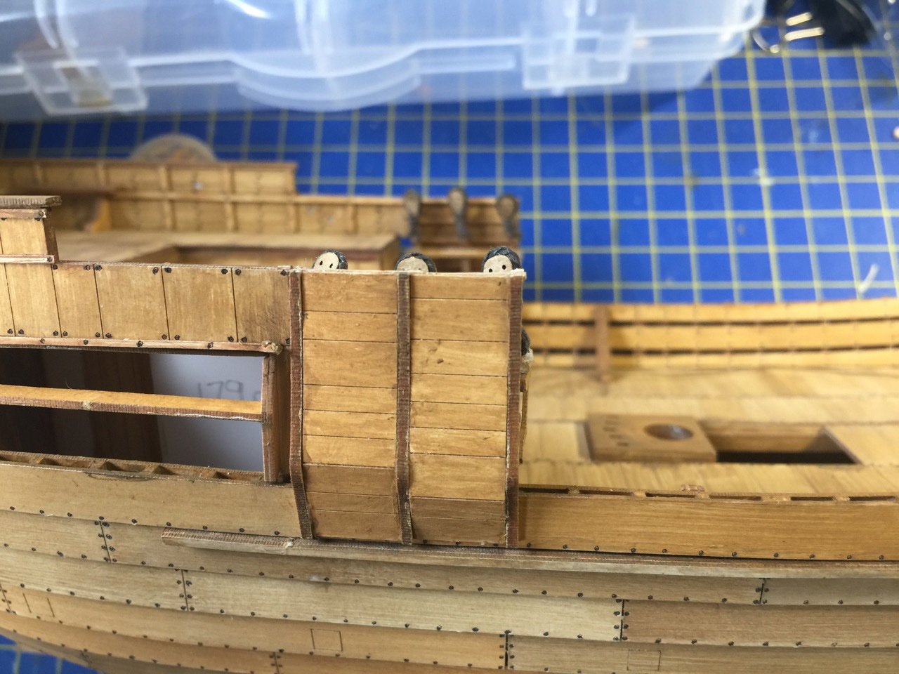
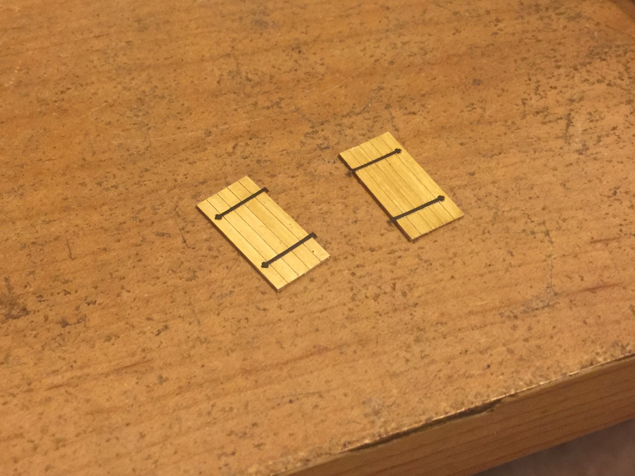
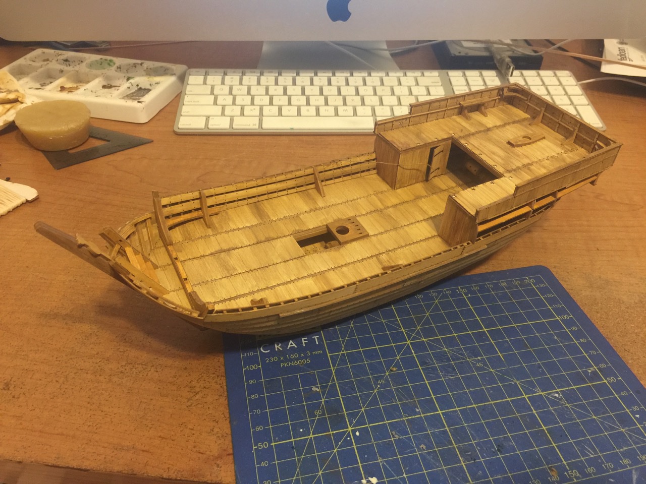
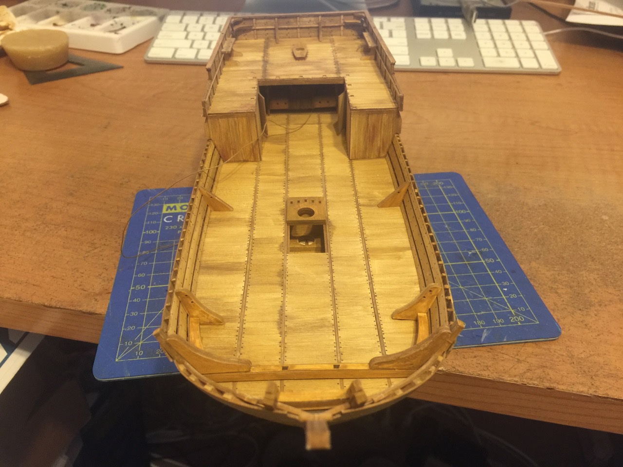
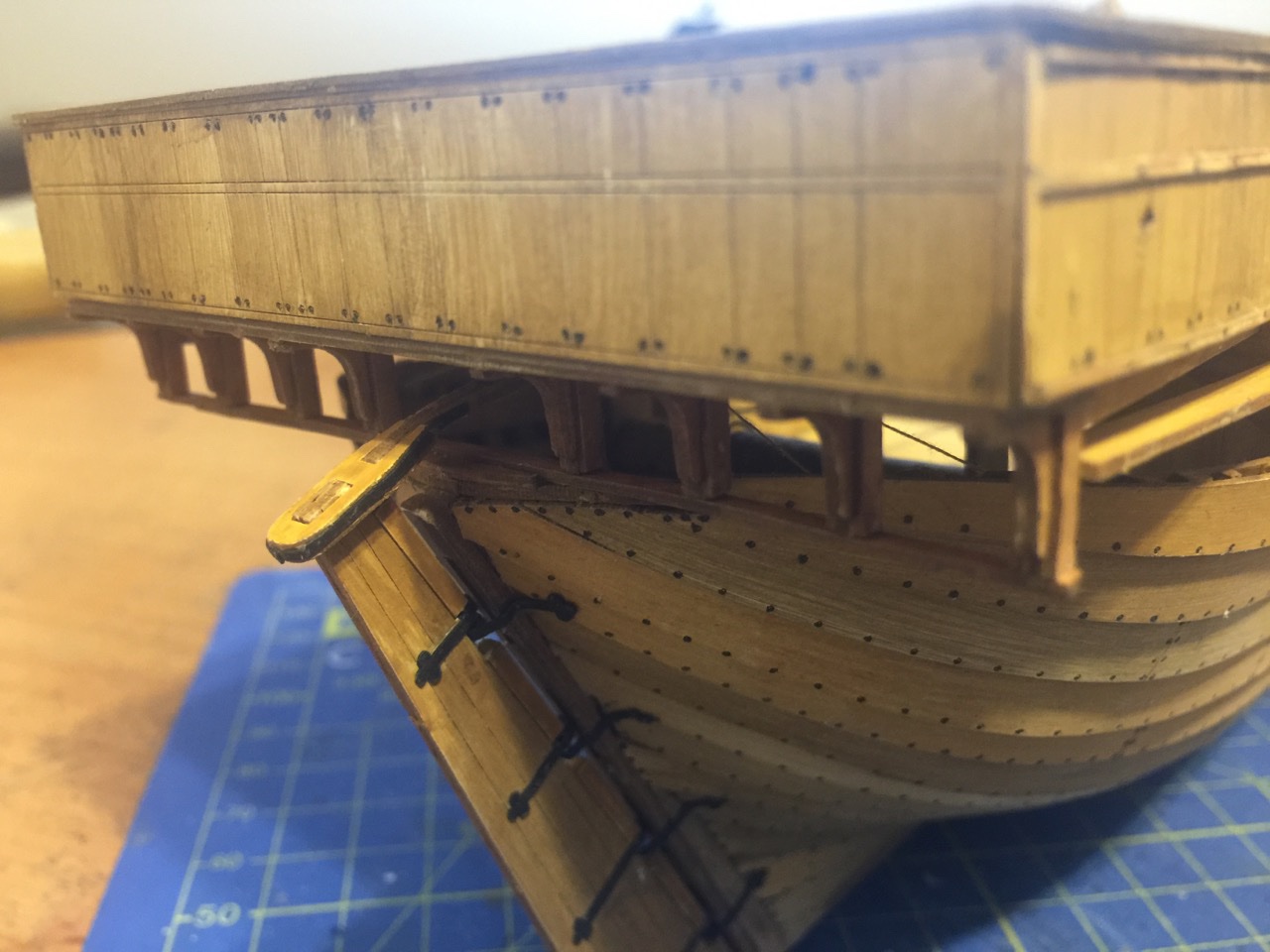
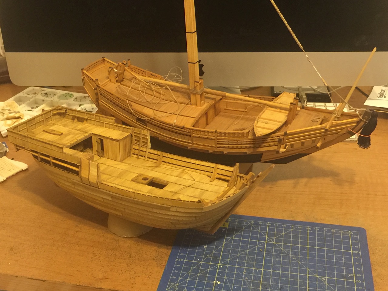
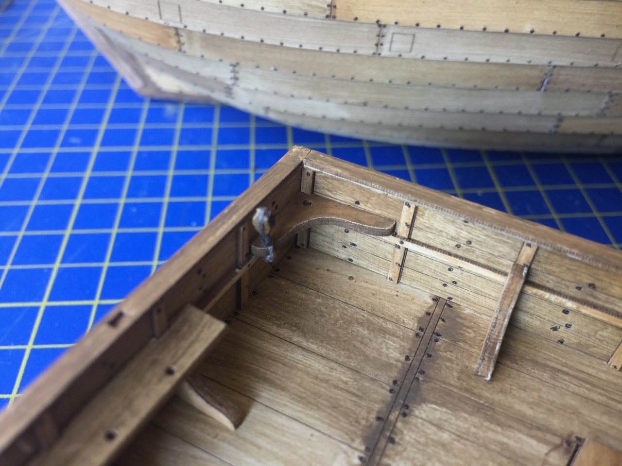
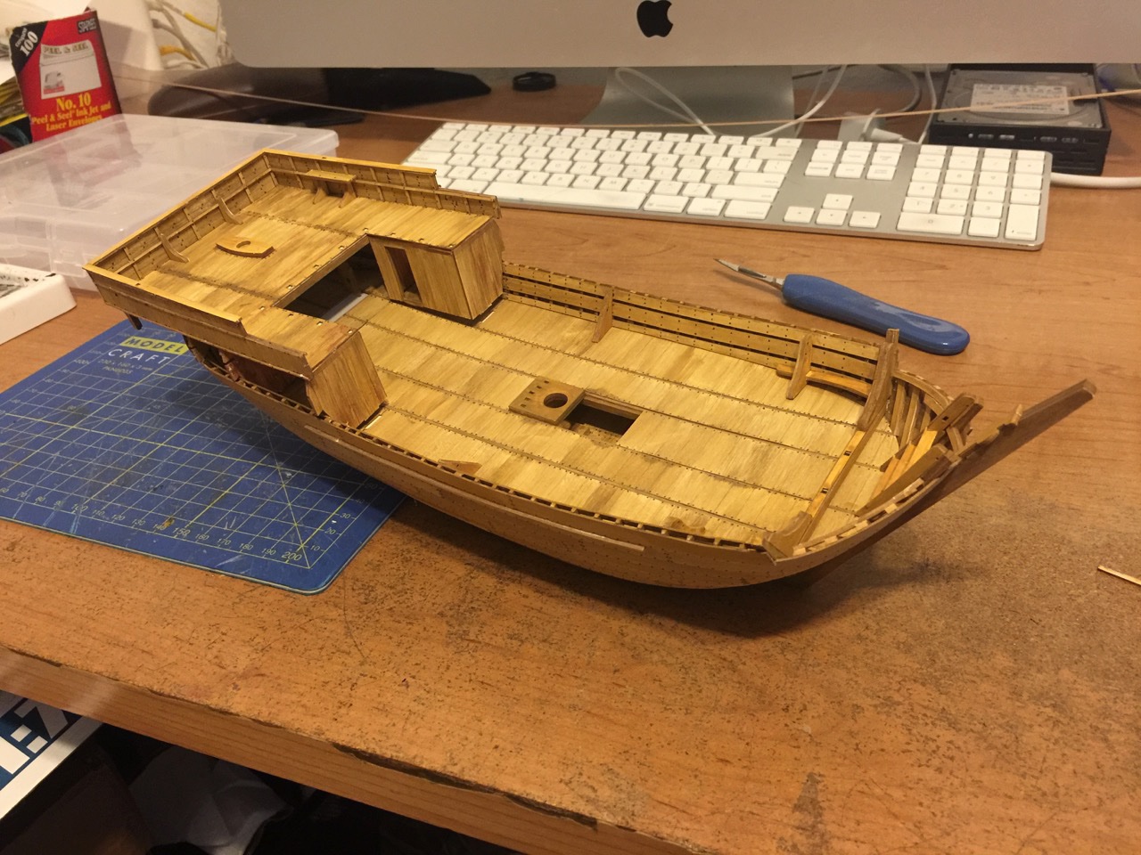
So, more progress as I've permanently mounted the stern castle structure. This wasn't easy, as there are a number of contact points, and there is some flex in the structure. I had to reach underneath with long, narrow piece of wood to put pressure on the windlass assembly in order to get it to fit into place. I think Shipyard should have just made the vertical supports extra long with slots in the deck to fit into. That would allowed for some variance in the way the whole stern castle structure fits into place. As it was, I had to apply a bit of extra pressure to hold everything down into place until the glue set. A little bit of paint afterwards hides any issues pretty well. First I had to make and mount the door, as you can see below. But, once those were in place, it was time to put it all together. So, now the stern castle is in place and I'm now working on these structures that hold the deadeyes. On later ships, the deadeyes were outboard of the hull and mounted on chain wales, or channels. On the cog, they are mounted inboard of the hull and mounted on inboard frameworks – kind of "ingrown" channels. Below, you can see these structures temporarily mounted in place. I still have to strop and attach the deadeyes before these are permanently mounted. But, it gives you an idea of how it will all look in the end. Though, I suppose the cover art does that just as well. I guess I just wanted to see my model looking more complete! In the last photos, the cog model is next to another 1/72-scale model, but a wooden kit of a Japanese coastal transport from a Japanese manufacturer called Woody Joe. That model is very close to completion as well. I basically just need to add the sail and wrap up the rigging. While it's a wooden kit, it's probably a good subject for a card version. Anyway, the Japanese ship is specifically a type of coastal transport called a Kitamaebune (key-tah-mah-eh-boo-nay). This is specifically one from the early 19th century. But, similar ships have been built since the early 1600s. If you're interested, I have another build log for it here: Clare
- 175 replies
-
- 7
-
-
- hanse kogge
- shipyard
- (and 1 more)
-
Louie, the one way around the issue is that the tiller ropes are almost impossible to see back there. They are behind that windlass. So, cutting those ropes would have allowed the deck to be fit into place. Not a great solution, but probably better than destroying the tiller or rudder head. Mark, well, it actually does kind of look like a workbench. Nicer than my actual work space! Clare
- 175 replies
-
- 3
-
-
- hanse kogge
- shipyard
- (and 1 more)
-
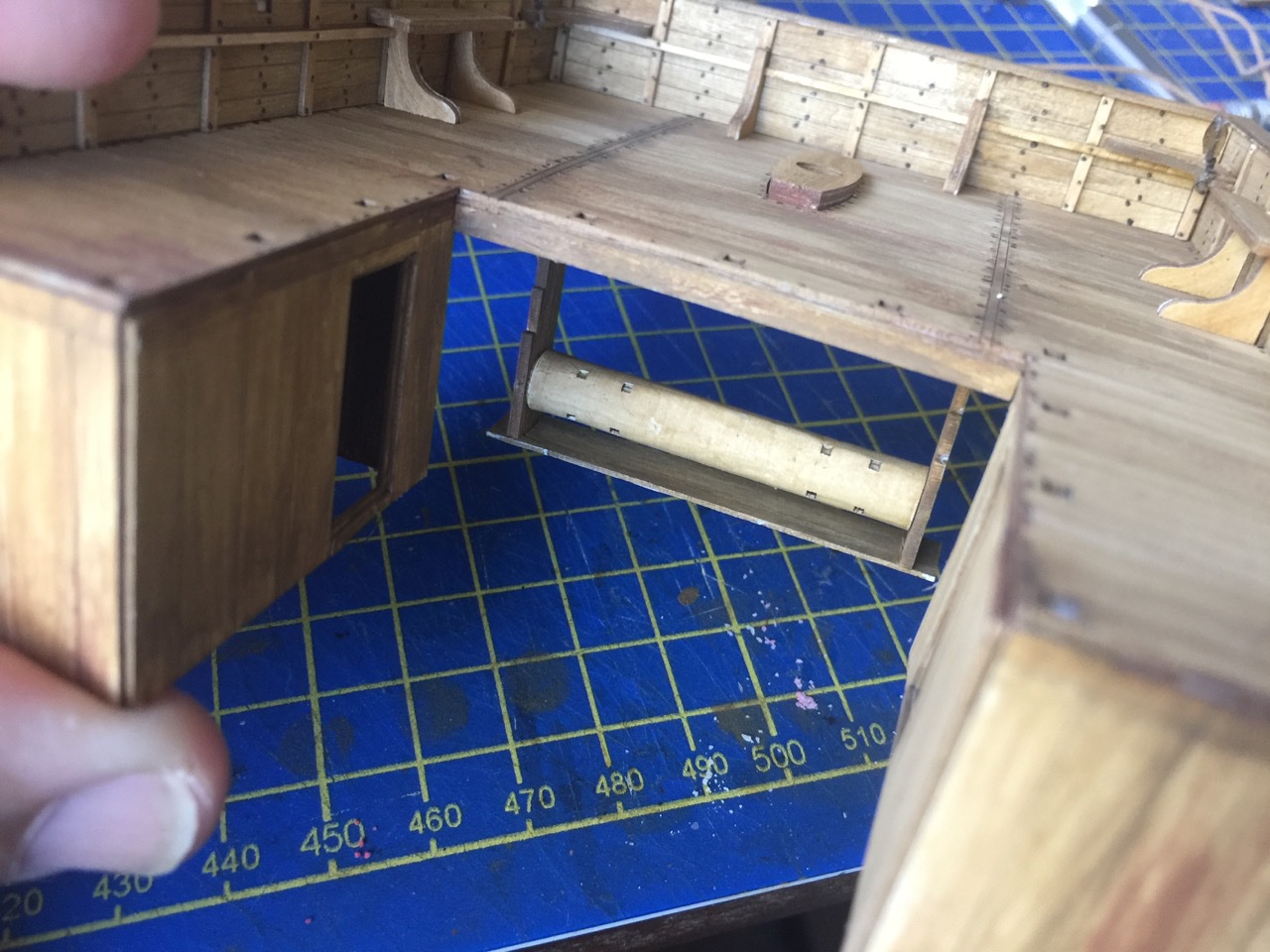
Thanks for the comments everyone. As I get further along and see fewer parts remaining on the laser-cut sheets, it's apparent that the end is still a little ways off, but it is in sight. There will be some rigging to do, but it's minimal on a ship with only one sail. Over the weekend, I discovered that once the tiller ropes are rigged, there is no way to fit the stern castle structure to the deck, except by removing the tiller from the end of the rudder. I didn't see anything in the instructions that tell you not the glue the tiller into place. But, it was such a snug fit, that I never glued it. So, I got lucky. Only later, do the instructions show the tiller, free of the rudder, allowing you to fit the stern castle into place. Once in place, the tiller can be re-attached to the rudder. I've had to start dealing with rigging line. The stuff that's included in the kit is all white. So, it's needs to be dyed or stained. Fortunately, I just happen to have some very old bottles of Floquil rigging stain (remember that stuff?) that I wanted to try out again. These are very old bottles I've had in the garage for some 20+ years, but found that they mix up well, even after sitting for so long. It's the last of my supply, but this is a small rigging project, so I thought I'd try it out again. I prepared some line for the tiller ropes and finishing rigging it. I also prepared some line to secure a few blocks into place on the model. Pretty soon, I'll be ready to fix the stern castle into place on the model. Below is the last item that I needed to add to the stern castle before mounting it. This is the windlass used for raising the sail. One more thing I'll need to do is to add wrap a length of rigging line around it for the main halyard. Clare
- 175 replies
-
- 6
-
-
- hanse kogge
- shipyard
- (and 1 more)
-
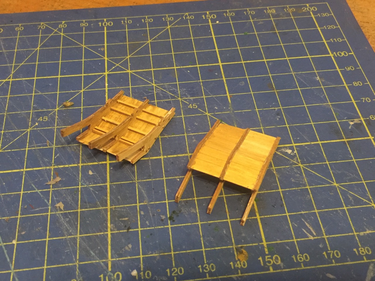
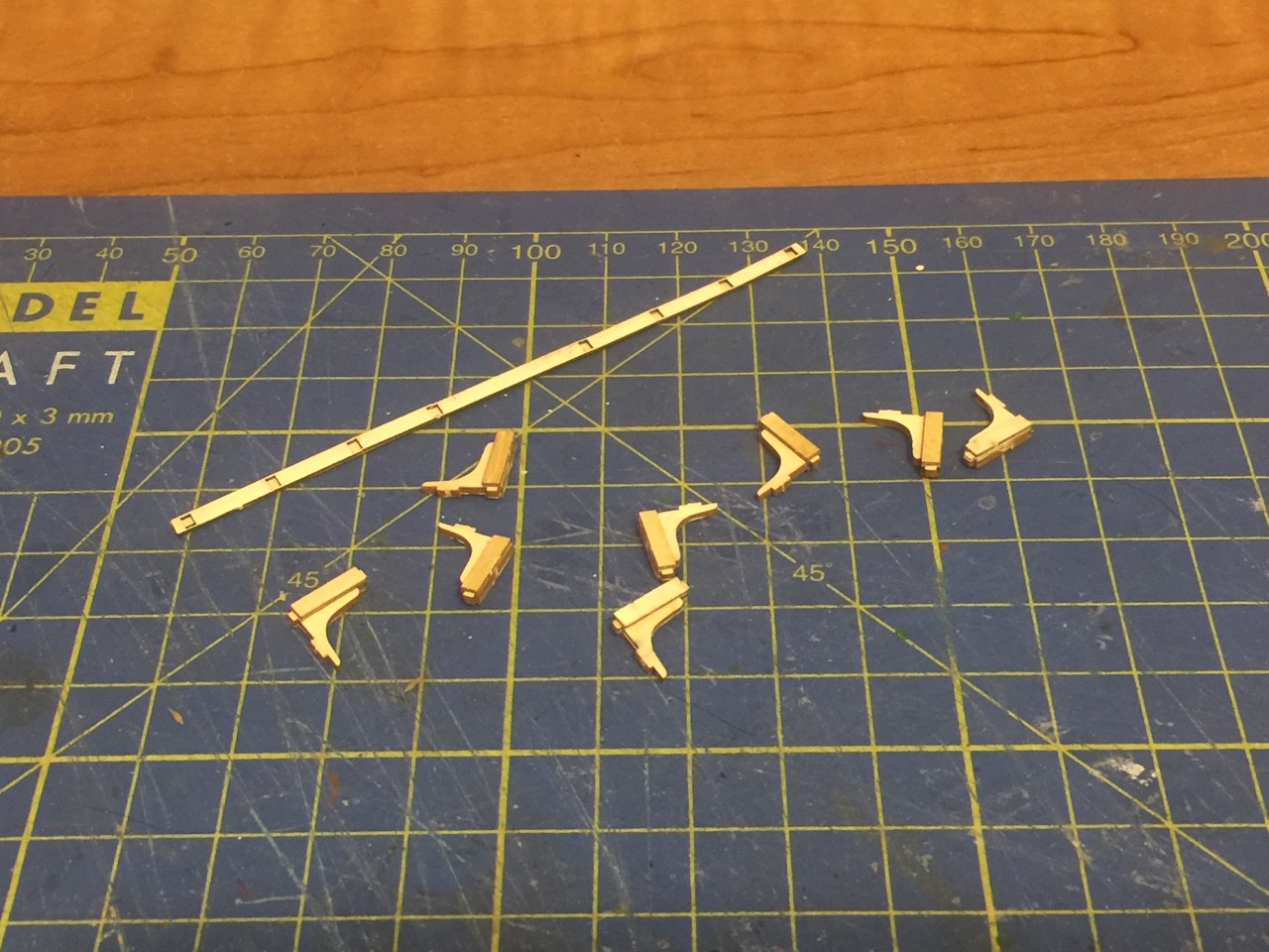
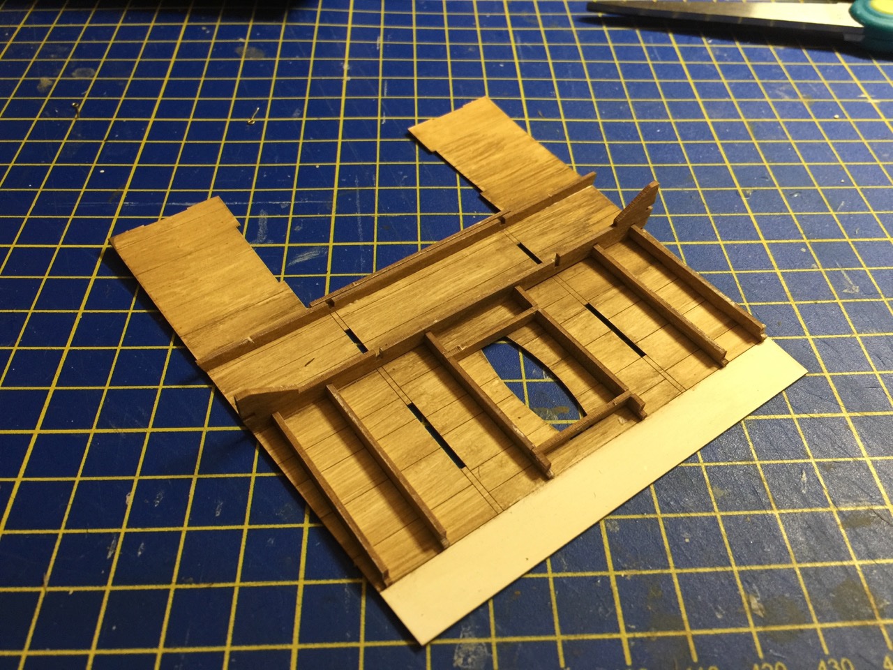
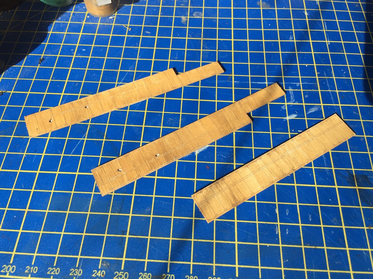
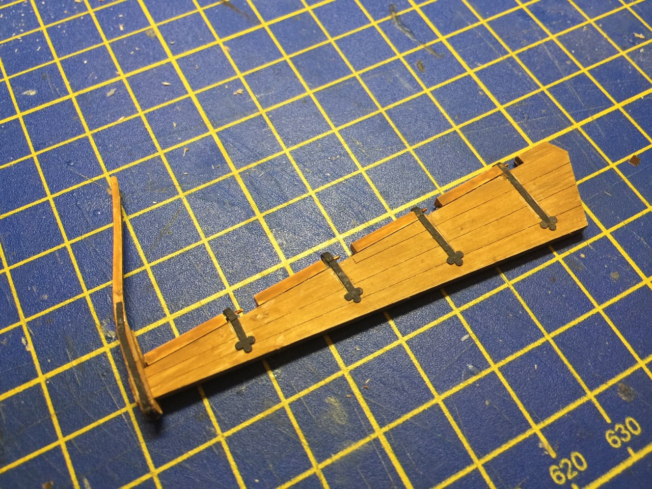
Hi Lapinas, thanks for the knife suggestion. Not sure how it's different from an XActo or a scalpel, and I do use both, but mostly the scalpel for the paper/card models. I'll have to check this out. Thanks for the links! Hi Popeye, glad you enjoyed looking over the posts. I'm getting to the stage where the model is looking more like a finished cog model and I'm starting to picture how it will look, mounted and on display. I was starting to question how the "wood" painting was looking, but the results are pretty neat now, as I'm starting to add more details. I'm actually feeling pretty happy with it. Plus, I made some comments earlier about difficulties I was having with the height of the bulwarks on my model, but that seems to be turning out not to be an issue after all at this stage. Here are a few more progress picture showing more stern castle details. Below are some parts assembled, ready to be painted and installed. That long rail piece is pretty flimsy. I think I'm going to have to paint it, then hit with some thin CA in order to stiffen it up. The CA will soak into this fragile piece and effectively make it into a piece of sturdy plastic. It is then supposed to be glued onto the tenons on the ends of those knees. Those may need a shot of CA too, as tenons like these tend to fray and you try to fit them. I added several parts to the stern castle structure and then I set the whole thing into place to see how it will all fit. Looks like there really won't be any fit problems at all now, regarding the bulwarks height. There may be a tiny gap at the fore end, but I think I can easily plug the gaps and paint them, so they won't even be noticeable. Bear in mind that in the photos, the stern castle is just sitting on the deck, not glued into place, so there are obvious gaps in the photos which won't be there when the sterncastle is glued down. Onward! Clare
- 175 replies
-
- 9
-
-
- hanse kogge
- shipyard
- (and 1 more)
-
Thanks Mark! Well, speaking of running with wide-open, full-speed throttle, I was just up your way this weekend – TWICE. Ran wide-open on a drive from Pleasant Hill in the SF east bay, to Shelton, Washington on Saturday. Kind of an emergency as I had to go get my mom from my sister's house and bring her back down here, wide-open, full-speed throttle in the rain – 24 hours of driving in two days(!). But, at least it didn't snow (much). And, otherwise, I'd thought about you and about contacting you for a visit. Well, before I went up there, I did make a little progress. Here's the top part of the stern castle. Lot of little bits I need to paint up and mount, yet, but it's something. I have to leave for another couple days to take my mom down to a nursing facility in her home town, so I'll be out action for another day or two, unless I pack up a few things to take with me. But, I'm only be gone one night. Oh, wait, I had to cancel Internet service and last time cell reception for my iPhone (to make a personal hotspot) was so bad, I couldn't do anything on the Internet. So, maybe I will take something with me after all... Clare
- 175 replies
-
- 7
-
-
- hanse kogge
- shipyard
- (and 1 more)
-
Ships at Trafalgar - what kits are available?
catopower replied to bruce d's topic in Wood ship model kits
I was going to put together a list for Ages of Sail, but nothing ever came of it. I think you have all of the available kits covered in what's been mentioned here. Only addition, sort of, is that Disar Model makes a cross-section kit of the Spanish ship Rayo. Don't know how accurate it is, their kits tend to be more for looks. Clare -
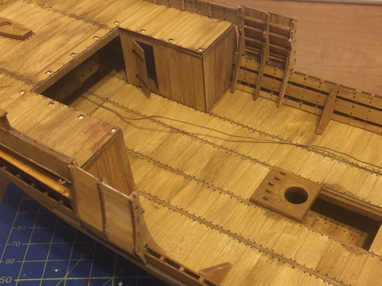
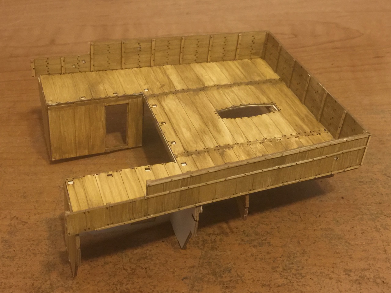
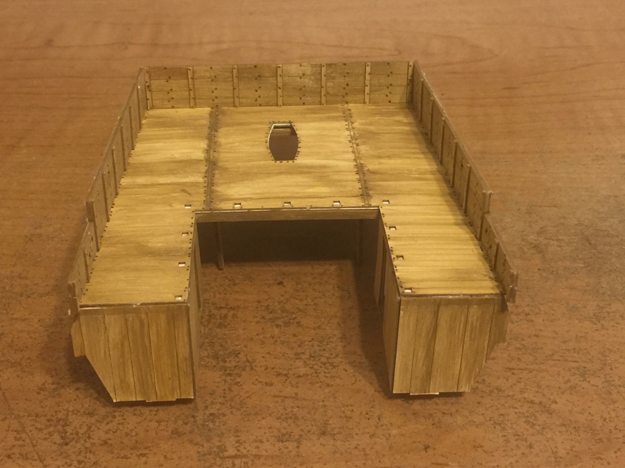
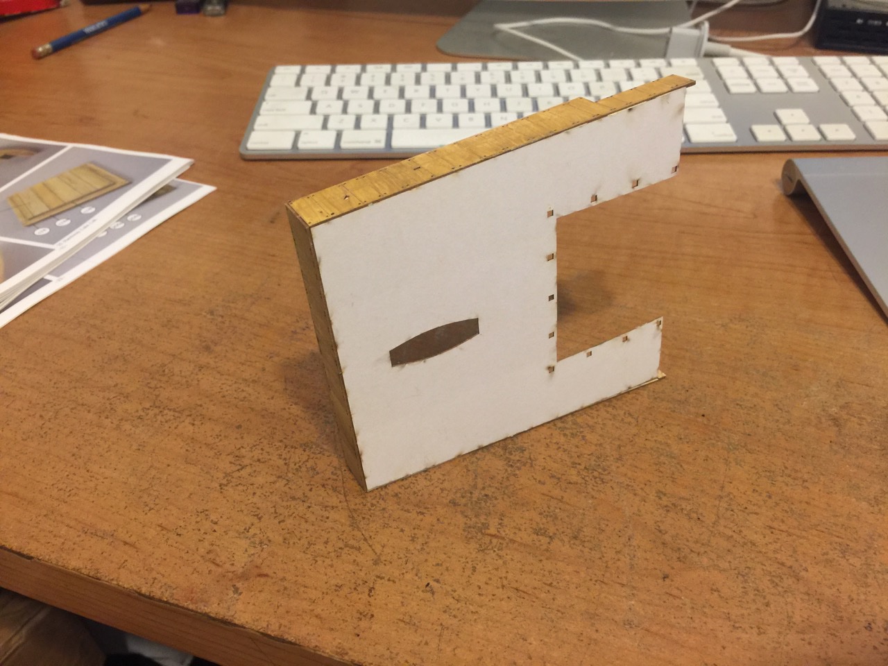
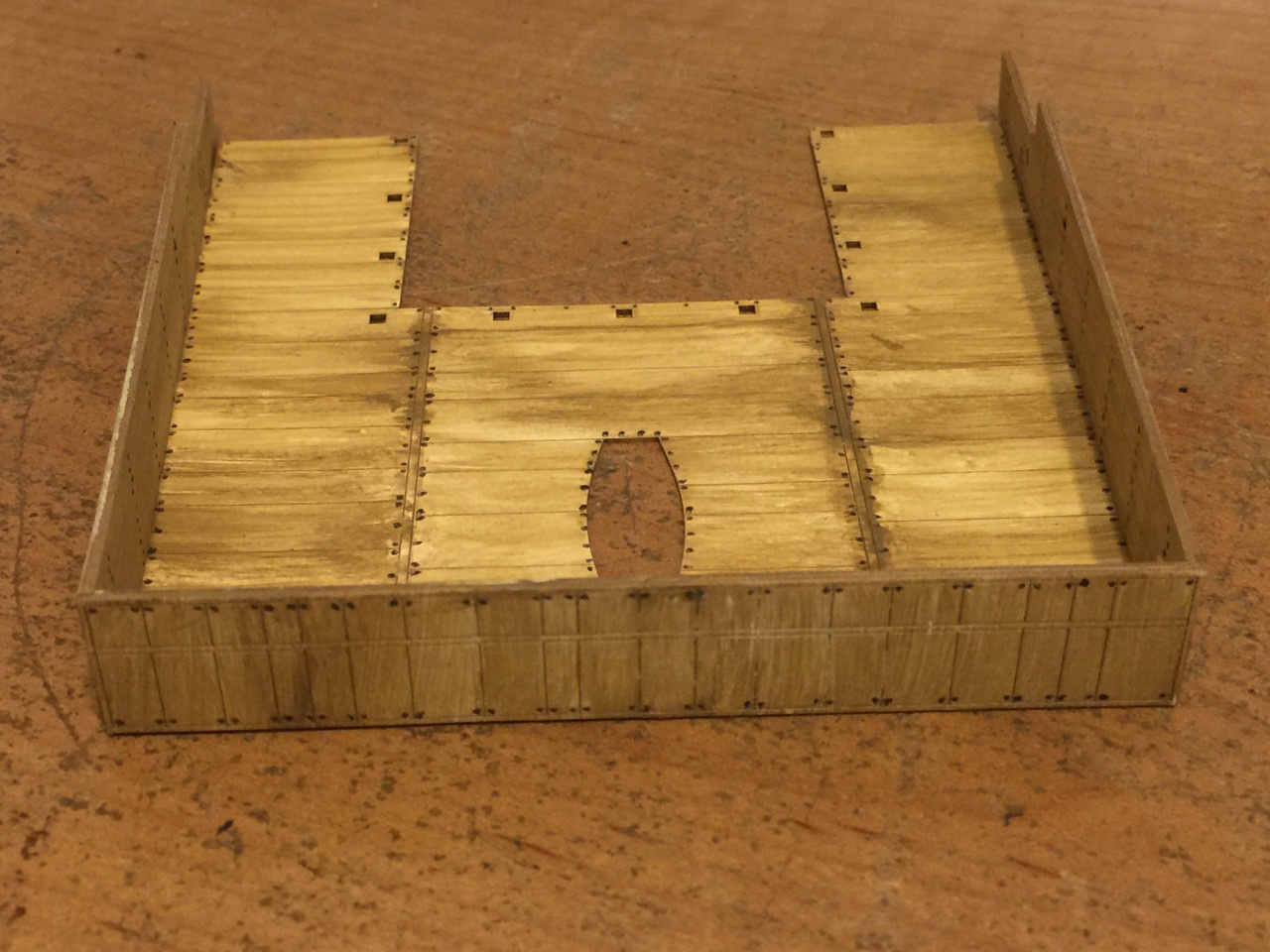
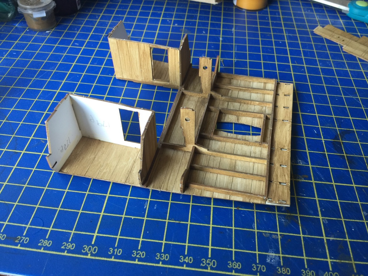
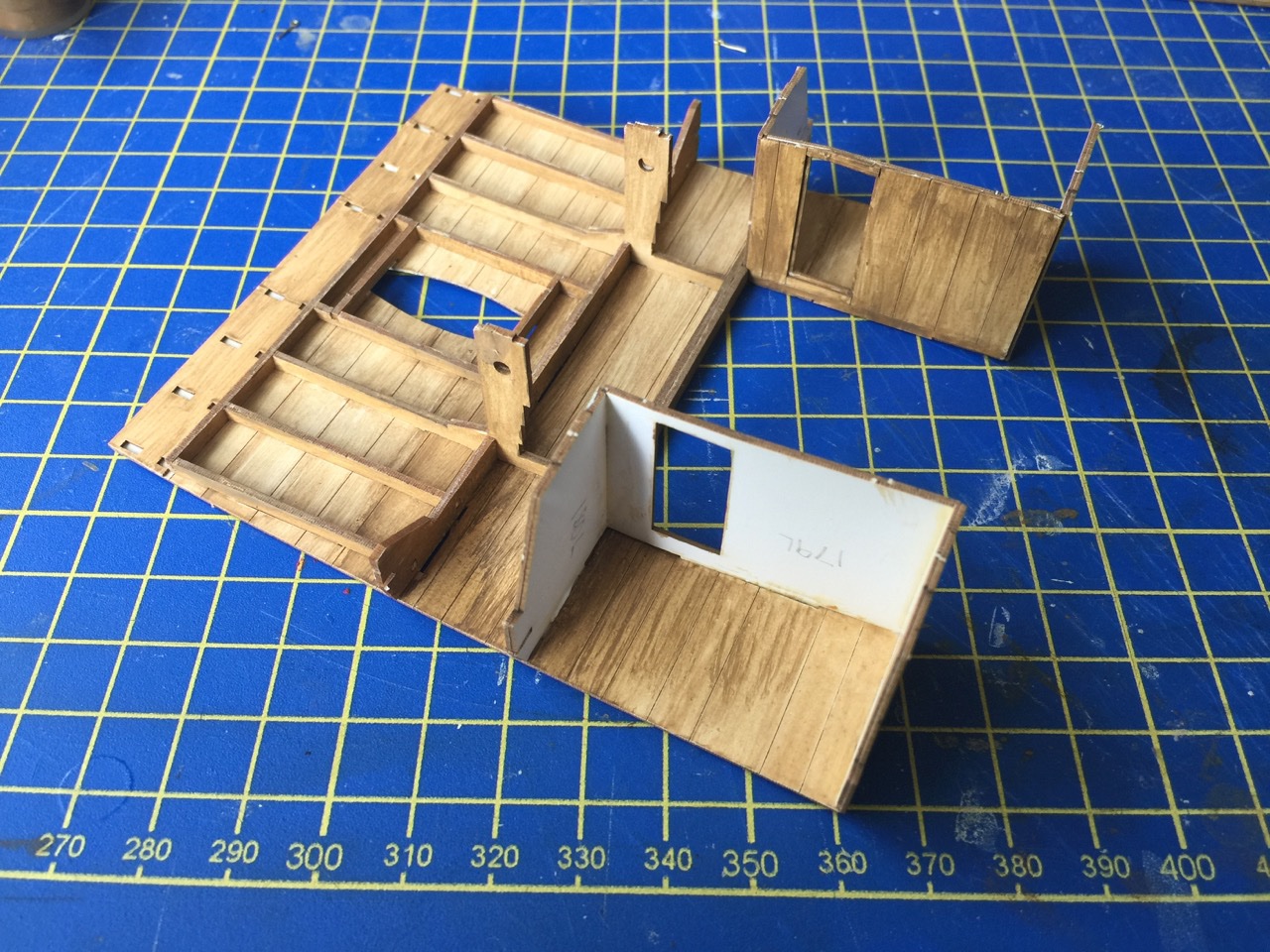
Thank you Louie, Druxey, One of these days, I will go on a quest to slay the carpet monster. But, I fear the action will only attract another one, or maybe something worse... In the meantime, it's important to stay ahead of the carpet monster, so I continued work on my cog. I've finally gotten to parts that are too big for the carpet monster to swallow. This is the underside of the stern castle deck. most of this structure will be very hard to see on the completed model, but it's nice to know it's there. So far, so good. There are two cabins added to this structure, one on either side. I didn't bother painting the interior sections in advance, as I wasn't sure if these would be visible. I think I'll go ahead and paint the interiors, though I think that only one wall may possibly be partially visible if the cabin door is open. But, the thought of the cabin door being open on a ship, just plants the sound of a swinging and banging door in my head. Hope the noise goes away... Finally, I'm making preparations for the top side of the deck, and assembled the solid rails (fences, walls?) that will surround much of the deck. It's only now that I realize I have a bunch of nail painting to do again. I THINK I'm getting near the end of the nail painting. Anyway, it's nice to be moving forward on this project again. Actually, it's nice to be moving on ANY project again. Been absent from any real ship modeling (okay, some might not consider this to be real ship modeling) for more than a month, so it feels good to be back. I went through some ship modeling withdrawals there for a bit. Now, I may be overdosing a bit, but it's only because I NEED it(!). Plus, I know I'll have to slow the pace shortly, so I want to make as much progress on my projects as I can now. Clare
- 175 replies
-
- 7
-
-
- hanse kogge
- shipyard
- (and 1 more)
-
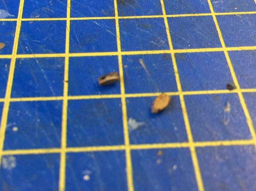
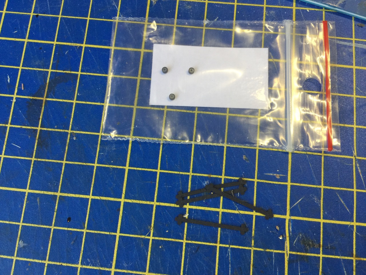
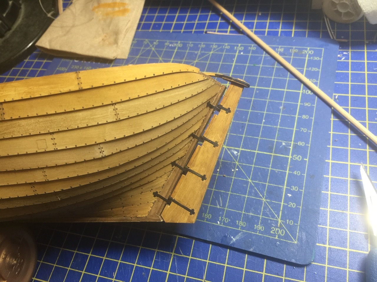
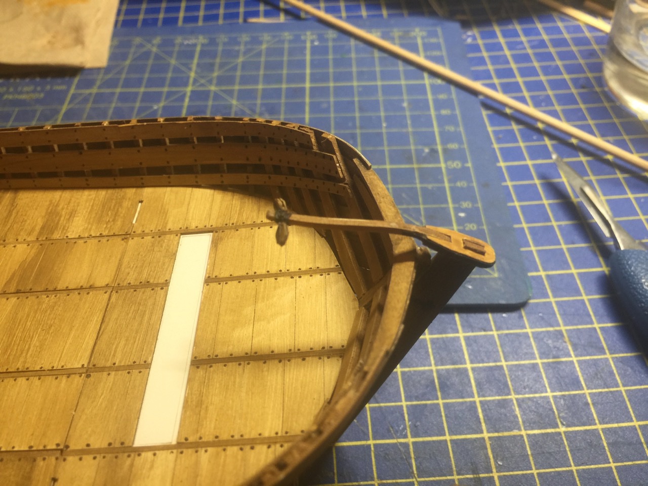
After having been away from any serious ship modeling for more than a month due to a family illness, I'm back home now and have been missing ship modeling so much, that I'm trying to get back to my many projects to get some things finished up. I'm still having a bit of a difficult time getting my life back to "normal" and I don't know if it's stress about family matters, the time change, the elections, being overly tired, confused about how to reset and regroup after having been away for so long, Covid-19 separation, or what. But, it is affecting me a lot right now, so I'm having to force myself to get restarted on things, and I did make myself sit down and start the next step on the cog model. First thing – I finally worked on finishing and mounting the rudder. First task was to make a couple blocks that will be needed. I went ahead and assembled all the blocks that came with the kit. If you're familiar with Chuck's larger-sized specialty blocks that he sells, these assemble in the same fashion. Sorry for the poor quality photo below. These blocks are very small and I had a hard time getting them into focus. The rudder came out very nicely. The hardest part was gluing in the ultra tiny doughnut-shaped pieces that are used in the rudder hinges. Shipyard gives you only exactly the number of parts you need, so the loss of a single piece will leave you short. And, unfortunately, one of the suckers jumped out of my grip and rolled into the abyss that is my carpeted floor. As you can see, there are three in the bag and I need four... Since I don't plan on swinging the rudder around much, I figured I could fake things a bit and get away with having the one missing piece. You can't see it anyway, as it's hidden by the black rudder irons. The rudder looks pretty good in place, so I think I'm okay with the shortage. Now, I'm just realizing how much more careful I need to be with the model, so as not to accidentally tear off the rudder. The kit comes with a mounting cradle. I don't know if I will want to use that, but I'm just realizing that it might be time to give some thought to how I'm going to mount this model. My normal "go to" for lighter models like this, is to use brass posts that fit up into the keel a little ways. That will be okay for a final display, but I'm going to need a working stand of some kind. The clinker planking will be a bit of an issue here, since I don't want to damage it in the process. But, in any case, here's my final pic, showing the tiller with the blocks mounted. I need to add some cleats next, but I haven't painted them yet, so I'm now prepping the whole laser-cut card sheet for painting, giving it all an initial coat of the light colored paint number 03 in the kit, before painting the wood color. Clare
- 175 replies
-
- 12
-
-
- hanse kogge
- shipyard
- (and 1 more)
-
This was the first ship modeling book I'd ever owned. Though it's not perfect, I learned a lot from it and got tons of inspiration from looking at the photos of shipmodels in the book. I never met Mr. Roth, but his wife Lois had maintained his ship model mail order shop, The Dromedary, for many year and I called them often. I have to admit to having a small crush on Rose, who worked for the shop... 😊 Clare
- 4 replies
-
- 3
-
-
- Milton roth
- lusci
- (and 4 more)
-
Actually, you're right in that it doesn't make much of a noticeable difference in that these kits don't actually require you to do any significant cutting. So, one razor blade is probably just as good as another. The only thing that needs to get cut most of the time are the little tabs that hold a part to its sheet. I'll still use the scalpel for that because of the comfy handle! It was only when I needed to cut some excess off of a thick, built-up card stock piece that I noticed that the thinner blades are really nice to use. The slice right through without applying much pressure.
- 175 replies
-
- 3
-
-
- hanse kogge
- shipyard
- (and 1 more)
-
Hi Chuck, I know what you're referring to. But, I think the difference is a more than you realize. Standard single edge razor blades are usually #12 size, which is .012" thick, though you can get #9 blades, which are only .009" thick. I mic'd the razor blades I have, and they come in at .0035" thick, or less than half the thickness of even the thinnest single edge razor blades. By contrast, my scalpel blades measure .015" thick. So, it seems that any razor blade will cut better than a scalpel blade. But, I'm telling you, these paper modelers using the shaving blades know what they're doing.
- 175 replies
-
- 6
-
-
- hanse kogge
- shipyard
- (and 1 more)
