catopower
-
Posts
1,900 -
Joined
-
Last visited
Content Type
Profiles
Forums
Gallery
Events
Everything posted by catopower
-
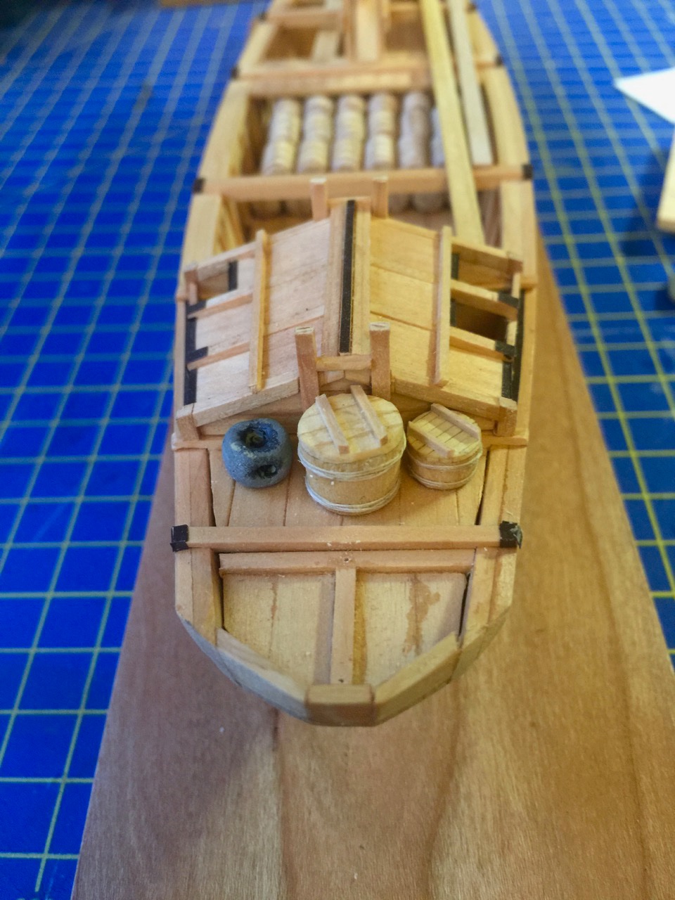
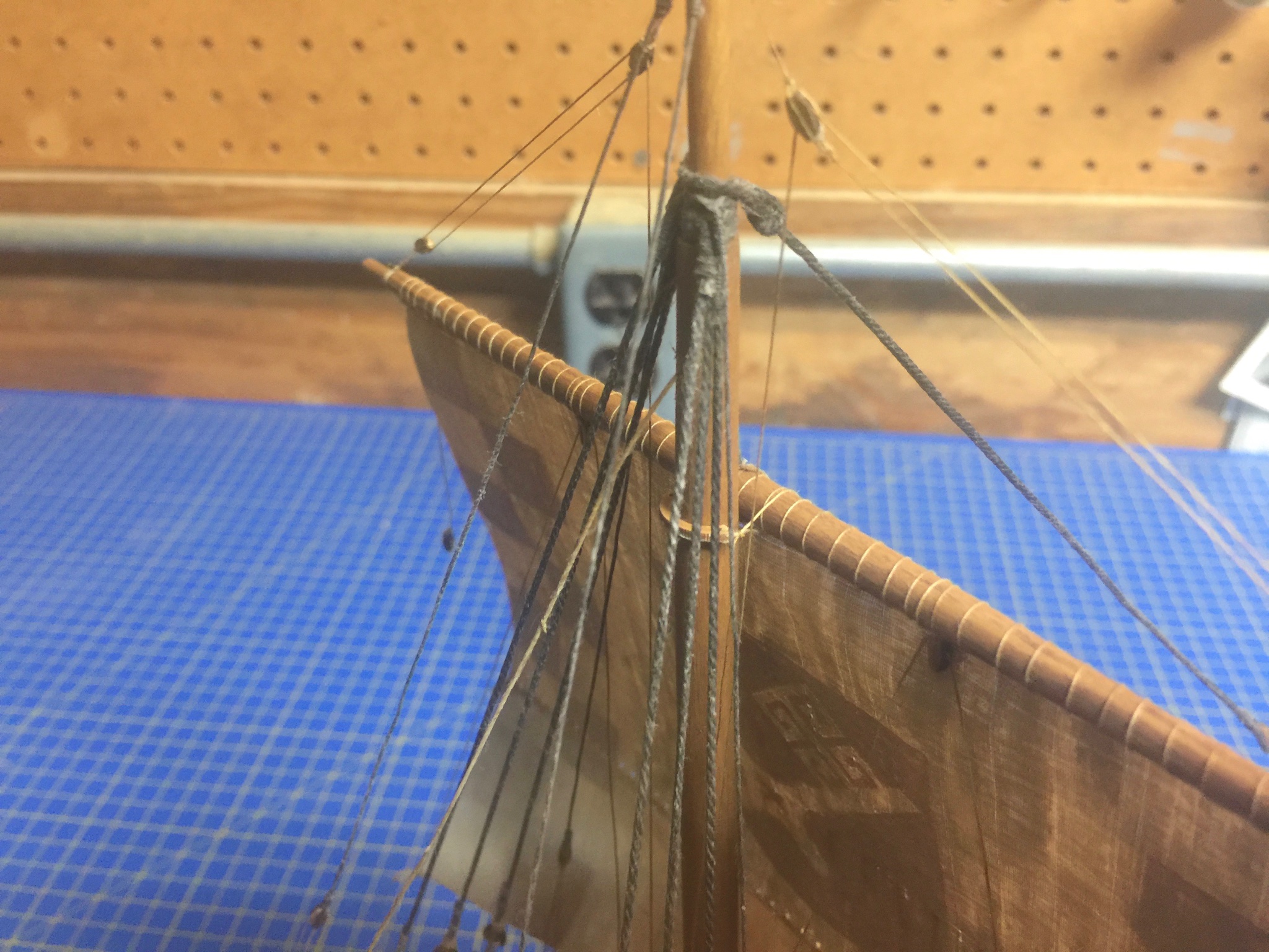
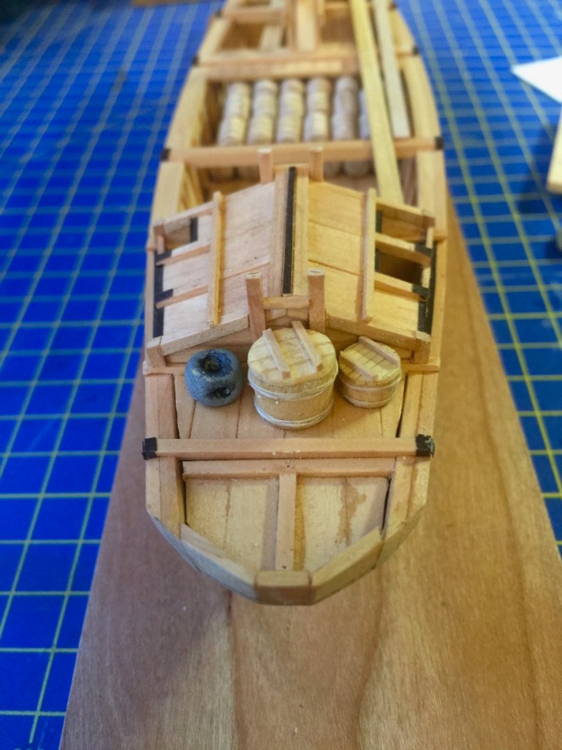
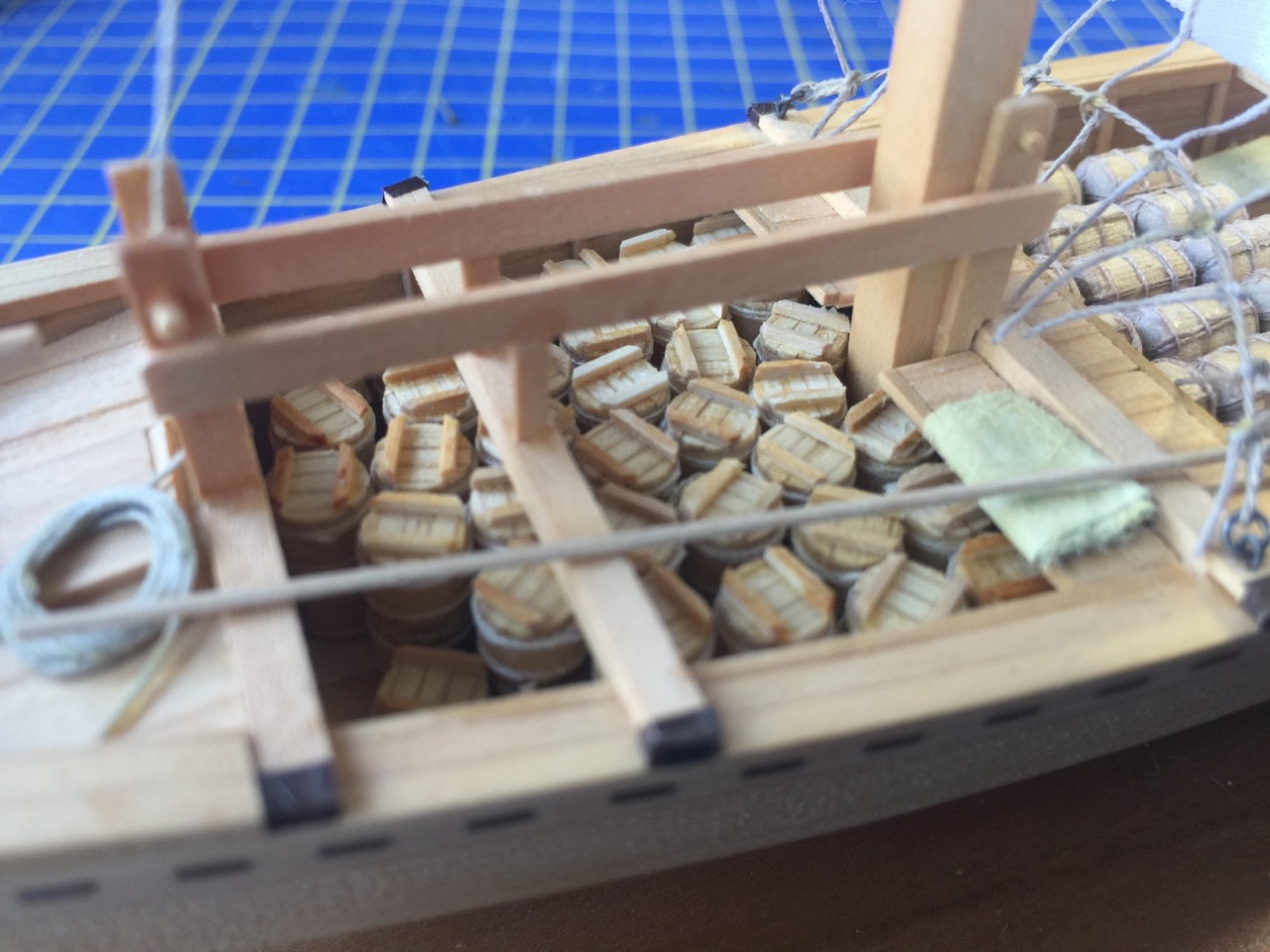
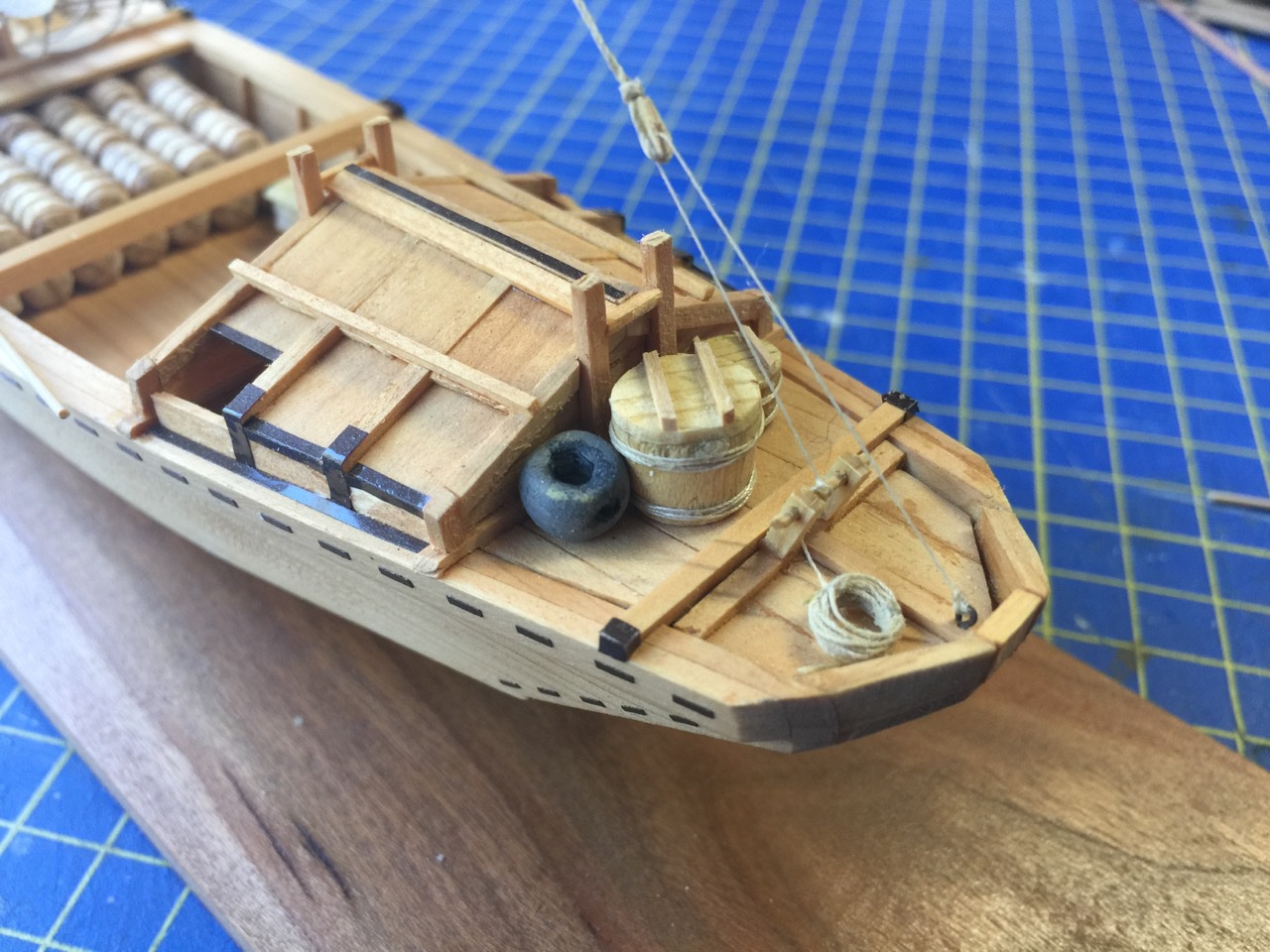
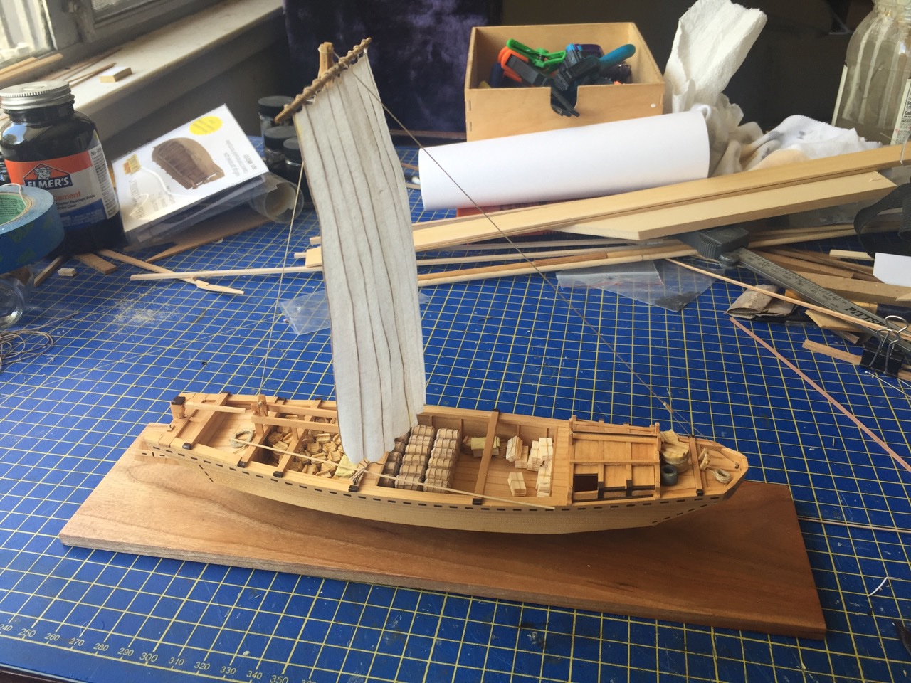
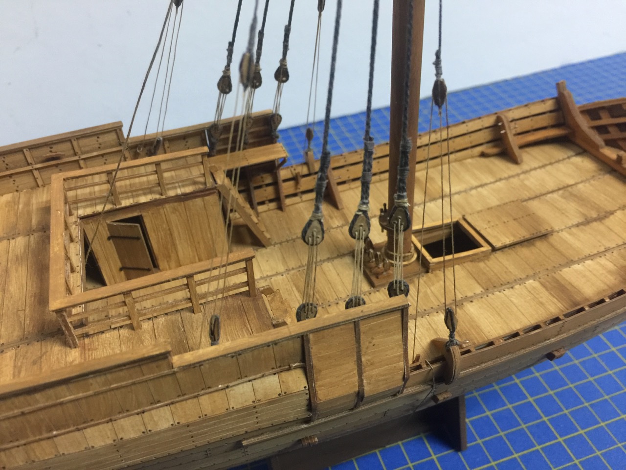
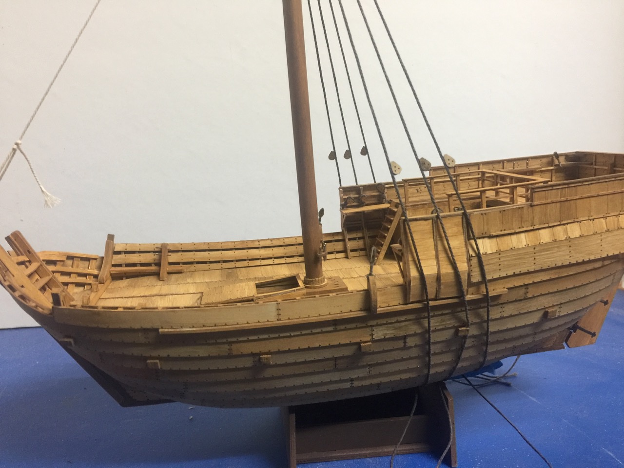
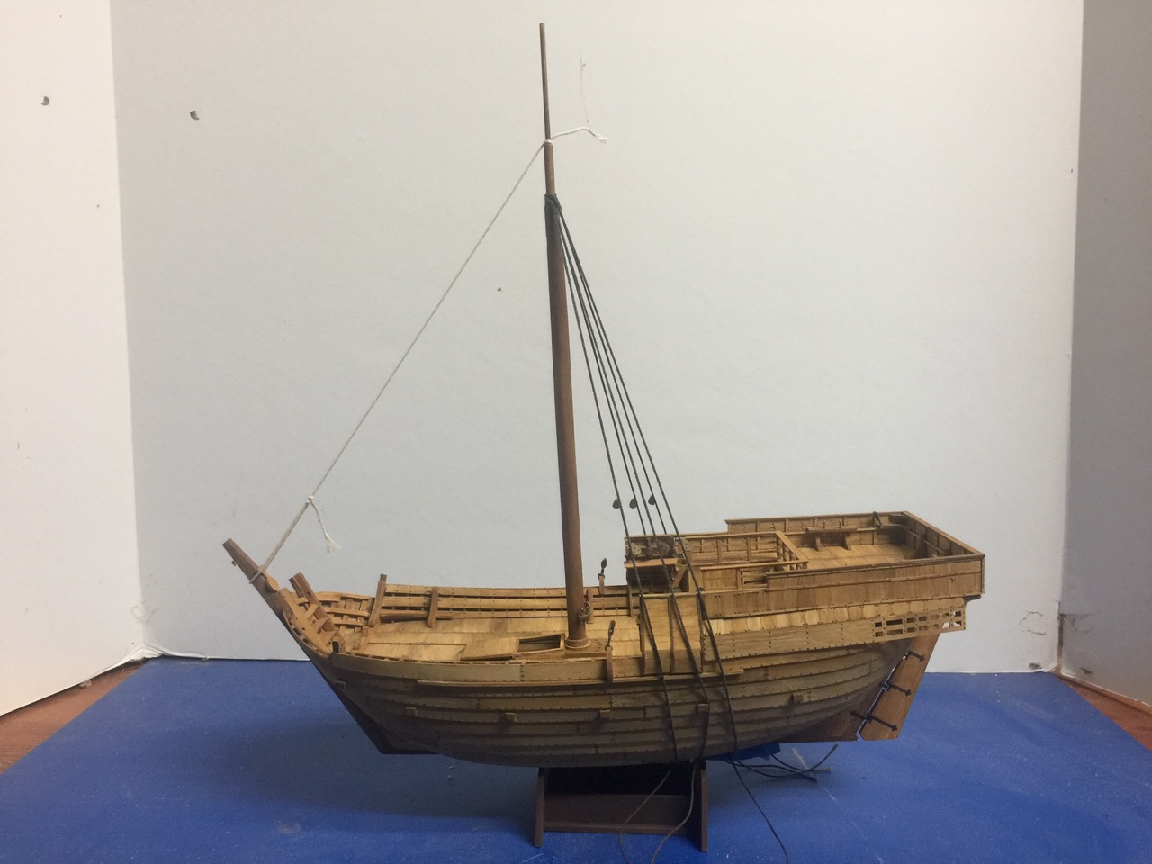
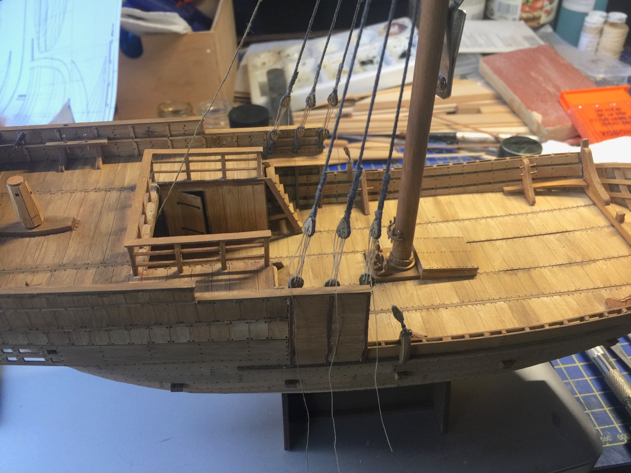
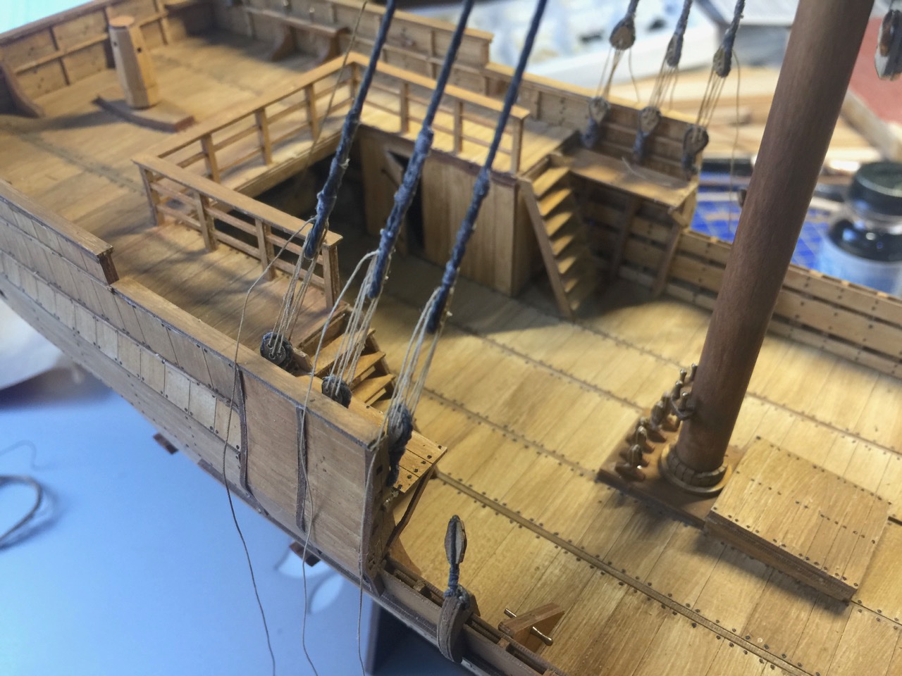
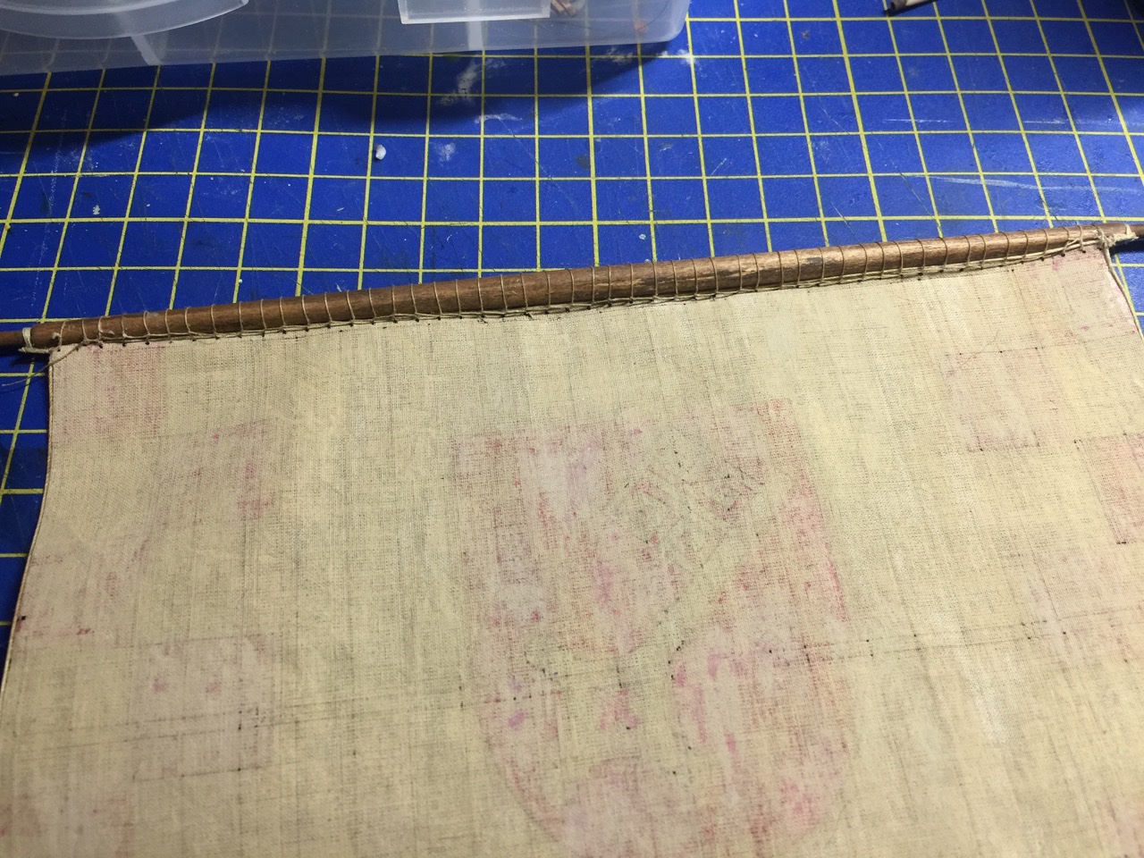
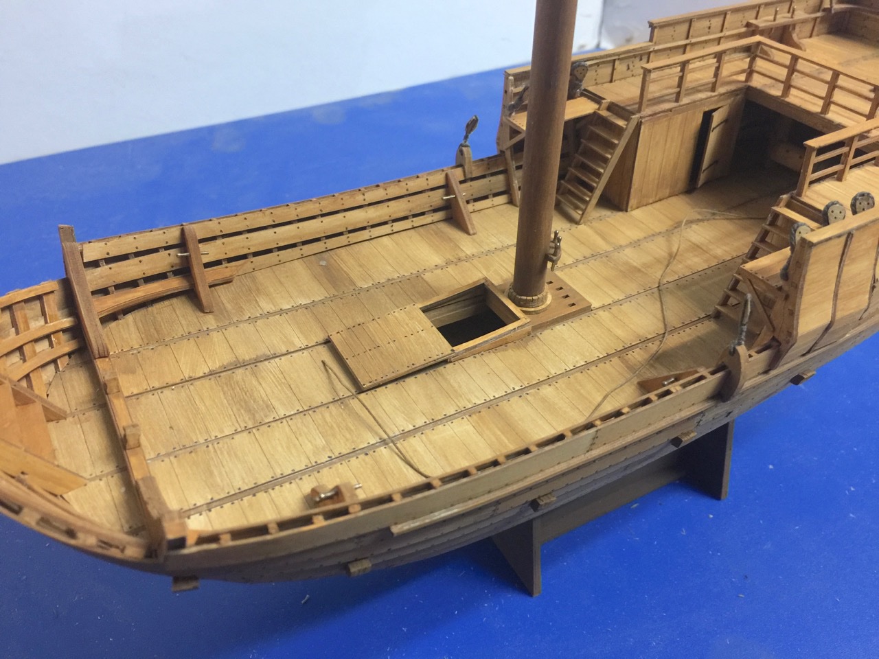
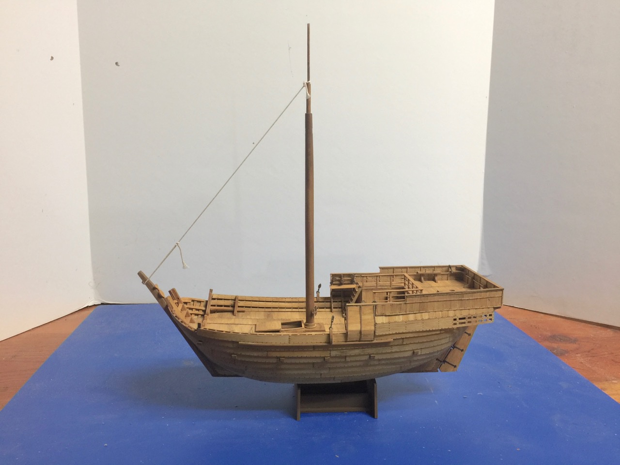
 With the completion of my Shipyard card model of the Bremen cog, I'm ready to get back to my Woody Joe Kitamaebune model. First, here are some update photos of my Tonegawa Takasebune... There's still a little more rigging to go, plus it not quite full of cargo. But, it's very close. Meanwhile, I'm hoping to apply what I've learned about making the sail for this model to the Kitamaebune. Unfortunately, I'm about to start yet another attempt at making the Kitamaebune's sails. I've lost count of how many attempts this has been. This is the fourth, I think. The last set probably would have been okay, but I discovered I'd made the sail panels too narrow. Not sure how that happened, as I thought I had everything measure out. To quote the famous Bullwinkle J. Moose "This time, for sure!"
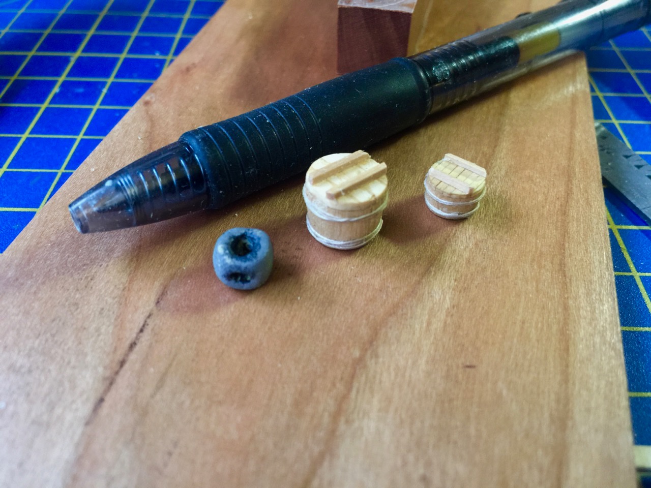
-
This is interesting. Every time I've checked Model-Space over the past several months, they've been out of stock on just about everything. Nice to see some of their part kit subscriptions available again.
-
Hi Robp1025, I don't know of anyone who has a payment plan. The closest is to use a credit card and pay that off over time. However, OcCre makes a few big kits that you can buy in parts. They're not as ornate as the San Felipe, but you can buy the "packs", as they call them, as you need them. They have the Spanish 74s San Ildefonso and Montañes, which were both at Trafalgar, the 3-decker Santisima Trinidad, which was also at Trafalgar, and the 50-gun ship Nuestra Señora del Pilar, an early 18th century Spanish treasure ship. All of these are big kits. Hope that helps.
-
Skipper1947, Unfortunately, the kind of subject you're looking at is more along the lines of what RC kit manufacturer produce. Those tend to have ABS plastic or fiberglass hulls. But, they often use some nice wood and brass parts for the details. The steam yacht Medea comes to mind. Dean's Marine makes a kit. Another is the Amati kit of the 1930s yacht Dorade. Or maybe Mantua's kit of the yacht Bruma. Don't know if that's any help. But these are the only kits I can think of that are even close to what you might be looking for.
-
I don't like that option as there's always some ugly guy on the other side looking at me instead of the model.
-
Thanks, Chuck. I guess it's only fair. since your build inspired me to get to work on mine. When the NRG conference finally does happen at the Channel Islands Maritime Museum, maybe we will both have cogs on display?
- 175 replies
-
- 2
-

-
- hanse kogge
- shipyard
- (and 1 more)
-
Thank you Druxey. I just hope the wind doesn't seem to be blowing on the flags more than on the sail!
- 175 replies
-
- 2
-
-
- hanse kogge
- shipyard
- (and 1 more)
-
Does this mean my Japanese models should be shown vertically? 🙃
-
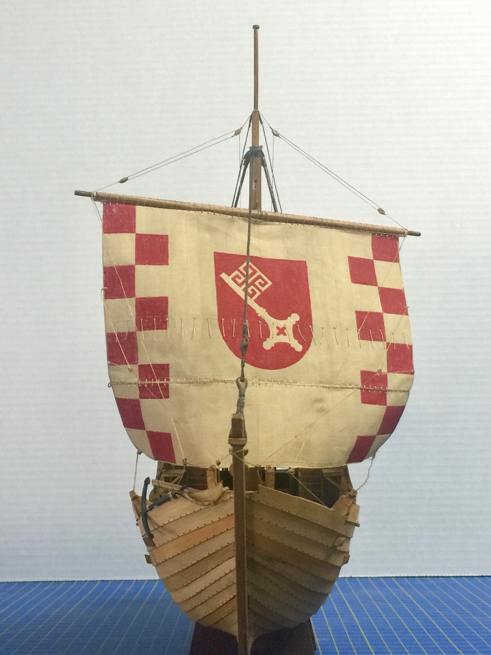
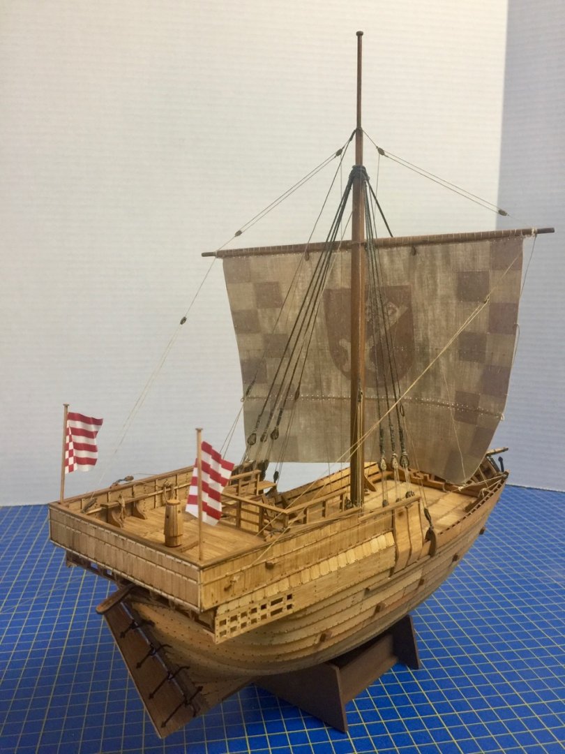
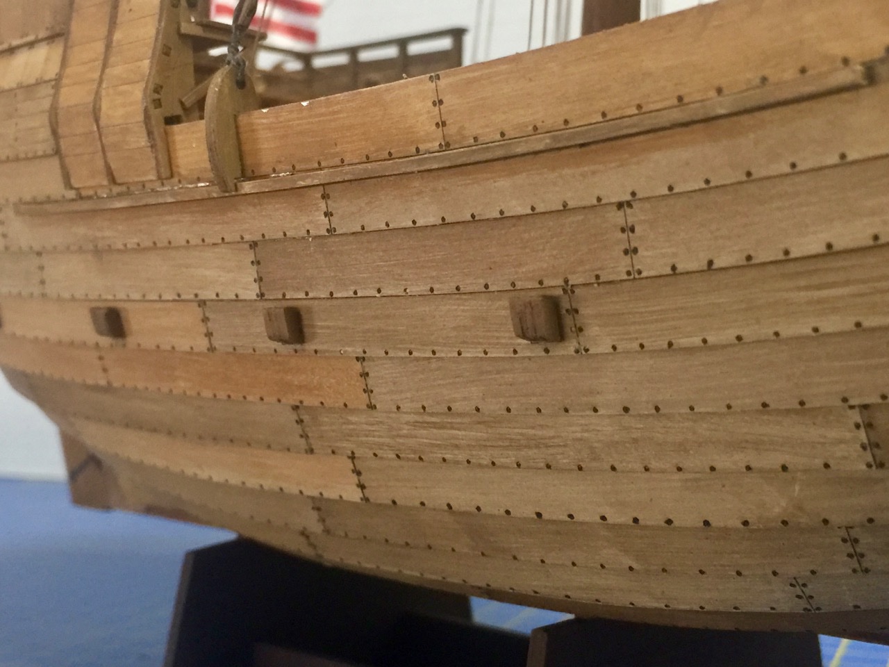
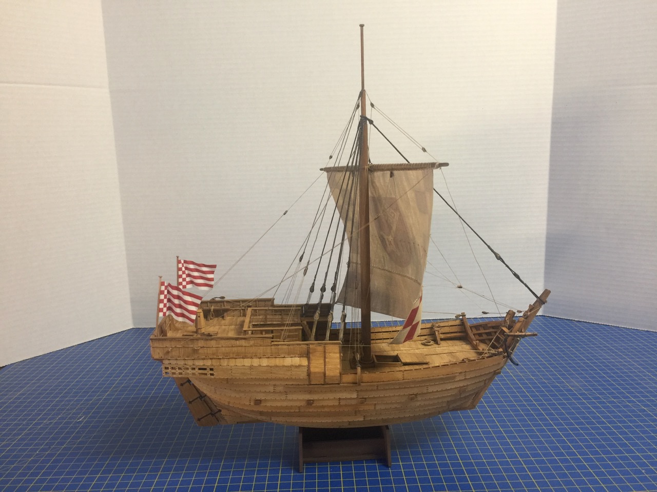
Here it is, May 1st, and the Hanse Kogge von Bremen is done! The ship was officially launched first thing this morning after a final rigging session that took place yesterday, after I discovered a couple lines I'd left off. The last step was for me to repair and reinstall the rudder, which has been knocked off so many times that I've lost count. This morning, she set sail and I took the opportunity to take plenty of photos. I'll post some of them here, but the majority will be in the gallery in a little bit. And so closes this chapter in ship modeling. This was my first card model that featured all laser-cut parts. My first card model was Shipyard's paper model of HMS Alert, which I thoroughly enjoyed, and was amazed at how it turned out. This model, I'm not so amazed by, but only because I now know what is possible from a card model. I'm very pleased with how it turned out, and impressed by this kit, which required no shaping of parts by me. Shipyard's technique for simulating wood by painting the white card stock work out quite well, though I couldn't follow their method exactly. You certainly learn with every model you build, and I learned or re-learned quite a bit with this project. I could see myself taking on another card model in the future. But, for now, I have some wood projects to get back to, include a couple subjects from my incomplete build logs here on MSW. So, I'm going to work on finishing up my Japanese northern port coastal transport next, among other things. Thanks everyone for your support on my Bremen Cog build!
- 175 replies
-
- 14
-
-

-
- hanse kogge
- shipyard
- (and 1 more)
-
Yep. Worst of the worst. I won't even repeat their name. You lose nothing if you enjoy the build and find a good home for the model, where it's appreciated. I have a friend who gives away every model he builds to friends and family. All big ships. He does it because he enjoys it. If you're in it for the money, then it become a business, and for many of us, that in itself steals much of the joy.
-
Hello Salty Dog, The way I look at it, even if you didn't get a lot for your model, you found a home with someone willing to part with $1000. That's a chunk of money for most people, which usually means it's something they'll value, care for, and show off. Your model isn't gone, it's just being displayed in another location where more people can appreciate it. And, you can use the money to help fund your next great work of art. I voted for the Royal Caroline, only because it's one I've always wanted to build, and I already inherited a San Felipe kit from a friend. But, I wouldn't worry about popularity of the subject here. Build what would bring you the most joy!
-
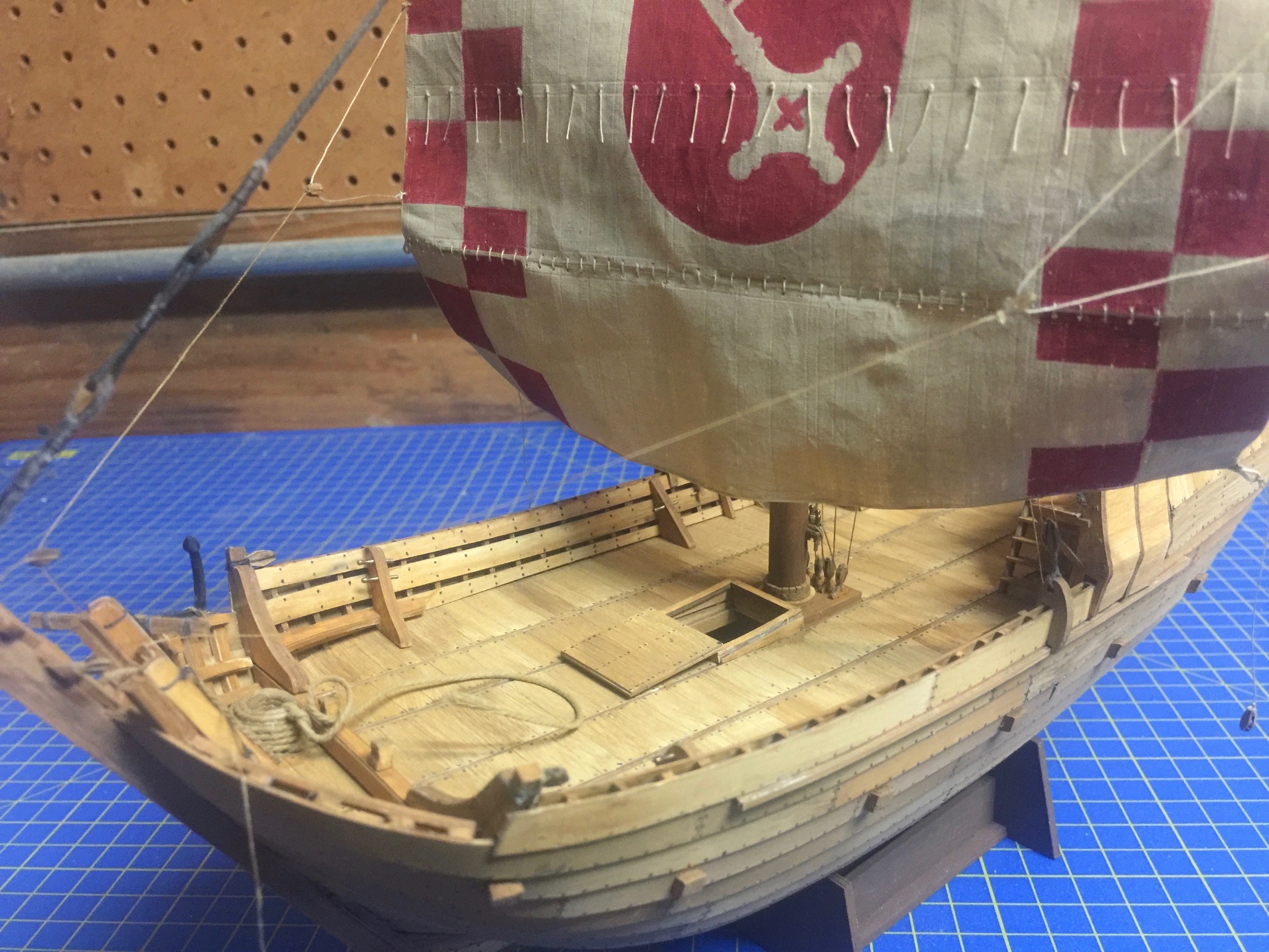
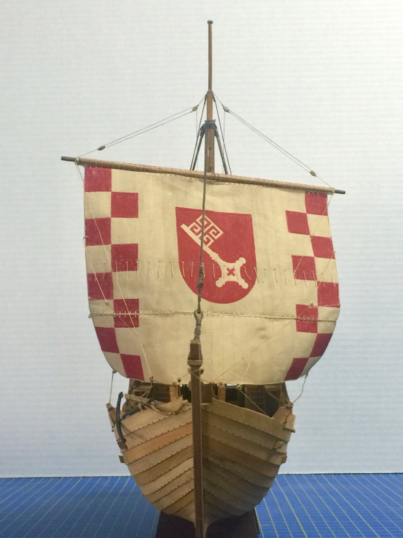
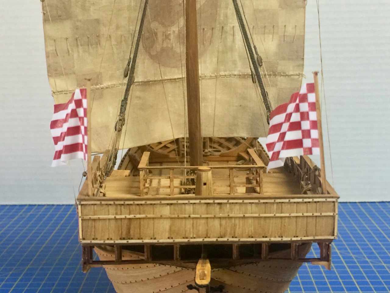
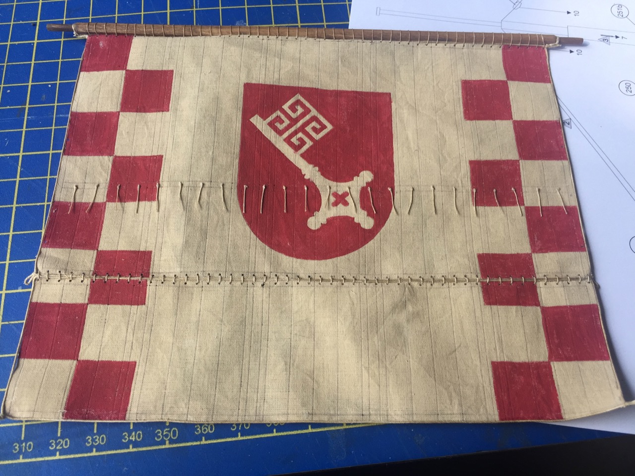
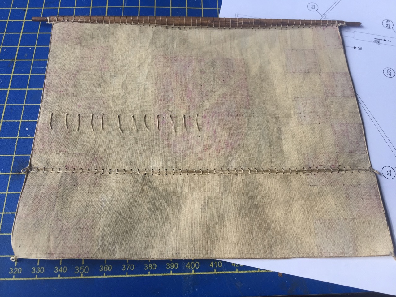
Hi Moab, thanks for the nice comments. I'm well into the rigging, but it's been a while since I've done any rigging work - Japanese boats have very little, if any. So, I'm not really accustomed to doing this kind of work these days. And it feels like the more I do, the more that's left to do. Kind of reminds me of one of those school math problems: Joe owes Ted $50. Ted agrees to let Joe make monthly payments equal to half of the remaining balance. How long before the debt is paid??? You can probably see a few loose lines, unused blocks, etc. There's still a little ways to go, but I kind of pooped out and didn't get anything done today. Still, we're oh-so-close to the end of this build! The one thing that's conceivably out of place are the bright new flags at the stern, given how well worn the rest of the ship looks. But, the kind of material the flags are made from feel a bit like plastic, rather than simple paper. I didn't think I could "fade" them effectively. However, I can justify them by noting that the flags were brand new, just purchased by the captain for this voyage. Anyway, they're not like the sail, which has to be kept up in all kinds of weather. Flags can be washed too. Won't be long now – stay tuned!


- 175 replies
-
- 8
-
-
- hanse kogge
- shipyard
- (and 1 more)
-
Hi Chuck, I used to make my own model rope from linen line. I had the crudest ropewalk ever (I could have probably won a contest), but it worked okay for me. Also tried to build a fancy motorized ropewalk, but had problems with it. I suppose I'll just get Chuck's Rope Rocket at some point myself. On wax, I tried conservator's wax, but I must not be using it correctly. It's Renaissance Micro-Crystalline Wax Polish. It goes on squishy and stays squishy, and it has a strong odor. I know people have been advising against beeswax, but it works well for me. And, so far, I haven't seen any model rigging degradation. The oldest model I have used it on is about 25 years old. So, I figure it will do.
- 175 replies
-
- 2
-
-
- hanse kogge
- shipyard
- (and 1 more)
-
Thanks Chuck, Hey, are you planning to use the kit supplied rigging line? That's what I'm using here. It's real linen line, but that makes it a little fuzzy, so I'm using a lot of beeswax on it. It also results in stiffer line, and I think the linen line is helping to keep the "twisties" to a minimum. Overall, I kind of like the aged look of the rigging line. Or, maybe it just reminds me of my 'old days' of ship modeling, before Syren rope, morope, etc.
- 175 replies
-
- 2
-
-
- hanse kogge
- shipyard
- (and 1 more)
-
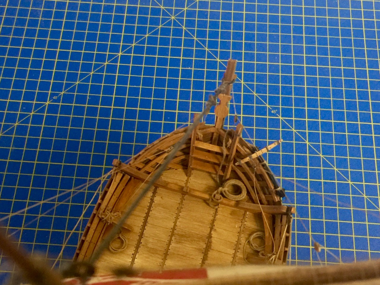
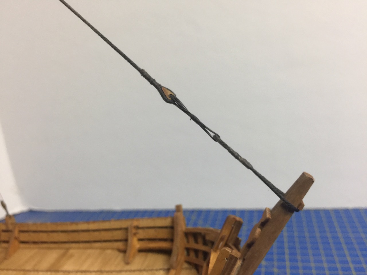
Druxey, okay, very pun-ney! 😄 Steven, yes, as Druxey pointed out, it's a clip. I often use those to keep tension on loose lines that I'm working on. In this case the halliard for the main (the only) yardarm. The halliard is wrapped around the windlass, and through a sheave hole (fake, as there's no actual sheave), and this also keeps the line from falling back out of that hole. But, the clip is also left over from using the halliard as a plumb line to help me gauge that the mast is straight.
- 175 replies
-
- 1
-
-
- hanse kogge
- shipyard
- (and 1 more)
-
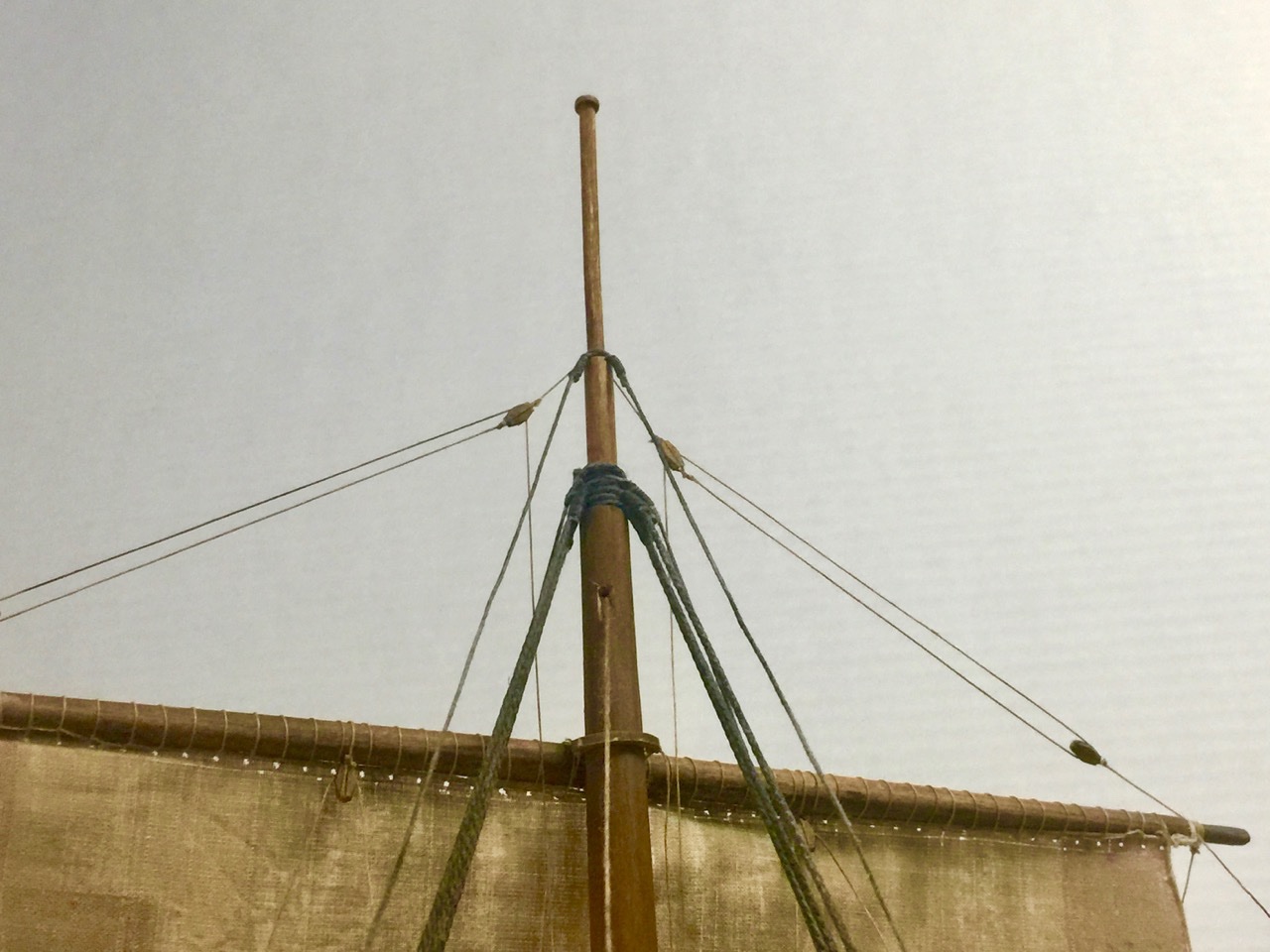
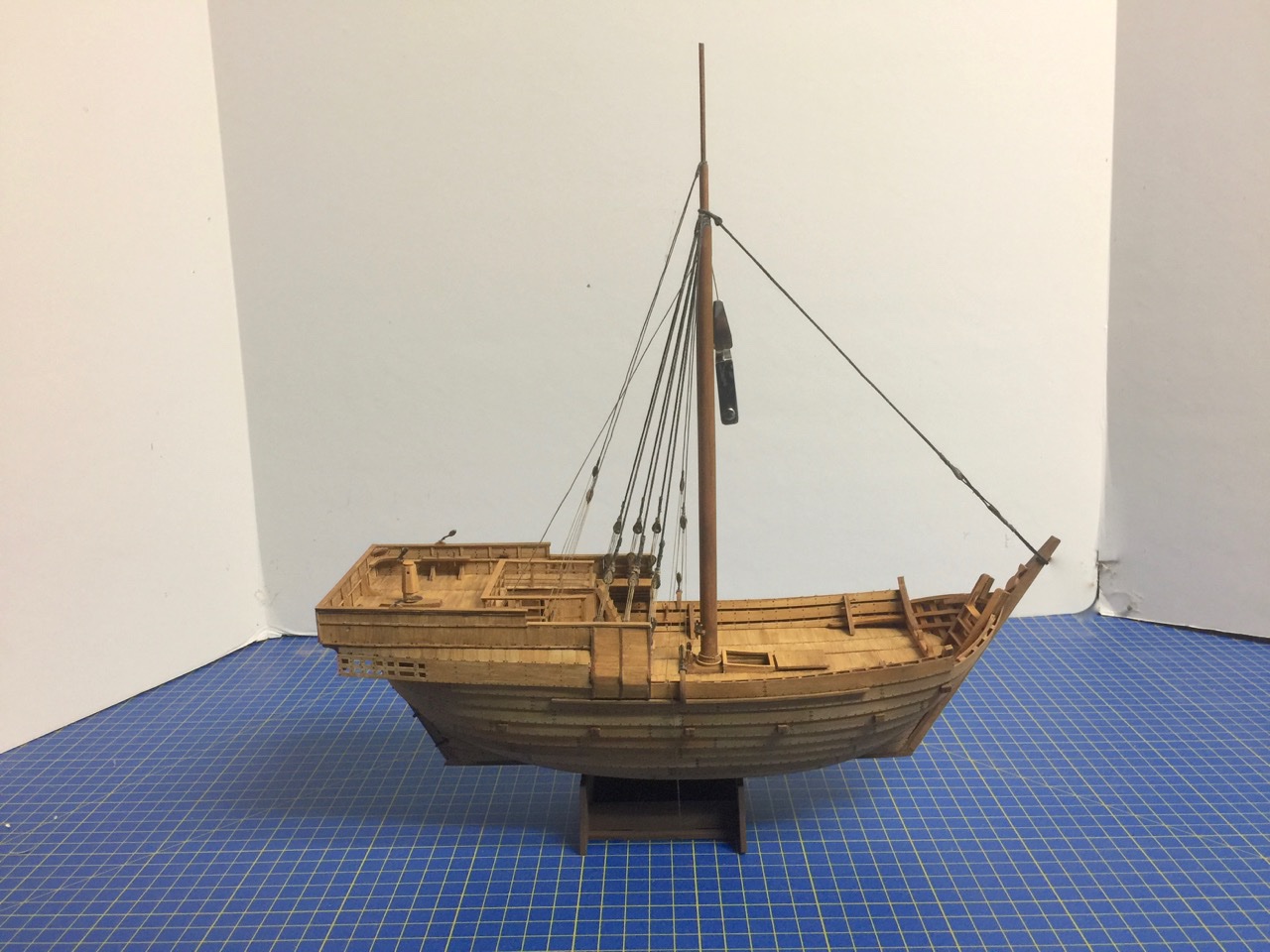
Well, I took some time today... to get the stays in place. And, it didn't feel right posting without any photos. So, here we go...
- 175 replies
-
- 12
-
-
- hanse kogge
- shipyard
- (and 1 more)
-
Work continues, and I've done quite a bit. 'But, I'm at the stage of rigging, where it seems that I have little to show for all the time I've spent on the build lately. I've been working on the main stay, the backstays, added brace pendants to the main yard, working on the lift pendants, added blocks all over... Still, nothing worthy of posting an update photo! Still, I predict in another week or so, I'll be wrapping up the rigging of the Hanse Kogge von Bremen model. Stay tuned...
- 175 replies
-
- 4
-
-
- hanse kogge
- shipyard
- (and 1 more)
-
Hi Mark, yes I do that with my wooden blocks too. But, wooden blocks stay open and these seem to close up again after I clean the holes. So, the stiffened line just buckles instead of passing through. I thought about using a needle threader, but I haven't needed to use one in many years, and I didn't want to make a special trip to the store just to fine one. I've found that, in general, if I use my own laminated computer printer paper to build up parts, I don't have this problem. But, parts made from thicker card stock, not just paper, tend to have a squishy, fibrous interior. They also often buckle, crush, or delaminate unless you stiffen them with something. Druxey, thanks for the nice comments. I try to be neat, but sometimes the parts fight me, and they often win...
- 175 replies
-
- 3
-
-
- hanse kogge
- shipyard
- (and 1 more)
-
It's great that they make the blocks and deadeyes in wood. The card blocks are actually very nice, but I just had to make sure to shoot them with thin CA to harden them up – the innards are otherwise too squishy and close up the holes, so I can't push the rigging line through them. I'm surprised you mention using Syren blocks, since they're an 18th century style blocks and the cog is 14th century. Do you think they're more fitting than the kit stuff? I'm not sure what 14th century blocks are supposed to look like, but these kit block certainly have an "old-style" look to them.
- 130 replies
-
- 3
-
-
- wütender hund
- hanseatic
- (and 2 more)
-
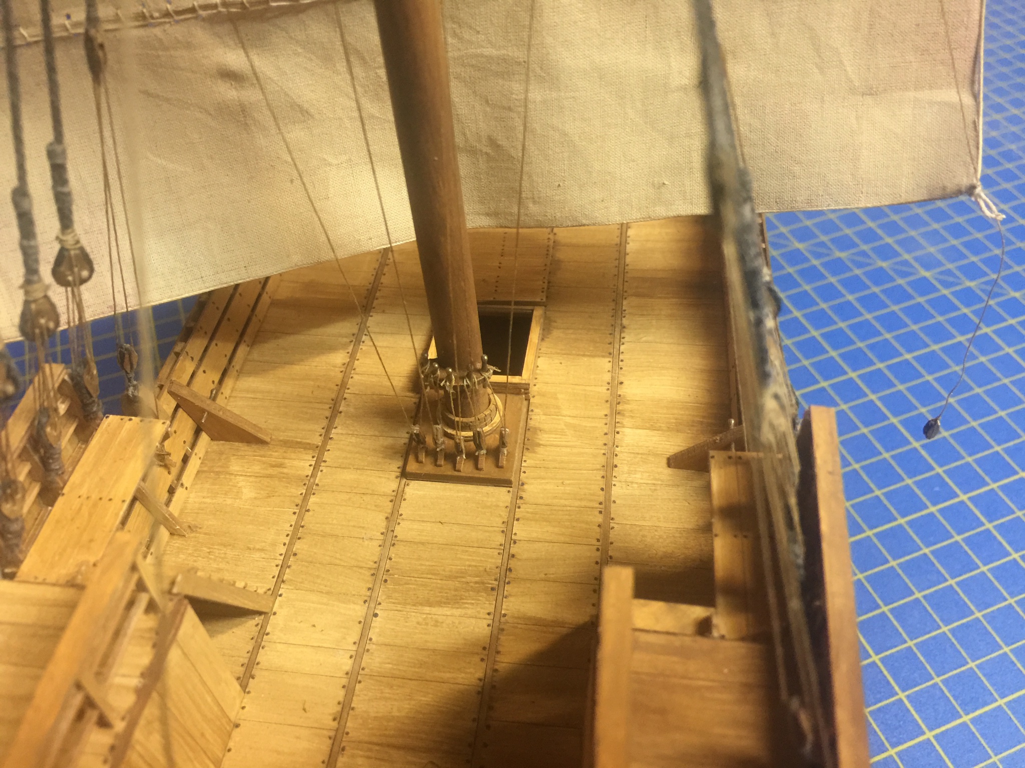
More progress... While working on the sail, I was also working on adding the shrouds to the mast. Today, I finally finished seizing the ends around the deadeyes, and started the process of reeving the lanyards through the deadeyes. The actual forestay will replace that white line, and I also have to rig a pair of backstays after the shrouds are complete. One issue I ran into is that the holes in the cardboard deadeyes close up from the soft cardboard material. I tried running a need through them to open them up, and I tried drilling them out. Problem is that they close up again – at least enough to keep the rigging line from threading easily through the holes. I finally use some thin CA on the deadeyes, which hardened the cardboard. Then, I could drill them out and the holes pretty much stayed clear. However, I did run the needle through them just before threading the line through. This worked like a charm. The only trick is that it was hard to reach the lower deadeyes and drill them out. I had to hold a block of wood behind them as I drilled out the holes. It was the only way I could get leverage on them. If you look closely, you might notice that I also added some of the blocks and cleats to the deck and hull. Still more of those to do. Of course, I still have to secure those shroud lanyards.
- 175 replies
-
- 9
-
-
- hanse kogge
- shipyard
- (and 1 more)
-
Chuck, good luck with that warping – it's definitely weird. Hopefully, it straightens out once it's fastened into place. By the way, I'm working on the rigging now on my Cog 'o' Card. Was just wondering, did Shipyard make some laser-cut wooden blocks for your kit? Or did they stick with their laser-cut card blocks?
- 130 replies
-
- 2
-
-
- wütender hund
- hanseatic
- (and 2 more)
-
Hi Chuck, yes that's all there is to them. I used Aleene's tacky glue. It seemed the safest bet.
- 175 replies
-
- 2
-
-
- hanse kogge
- shipyard
- (and 1 more)
-
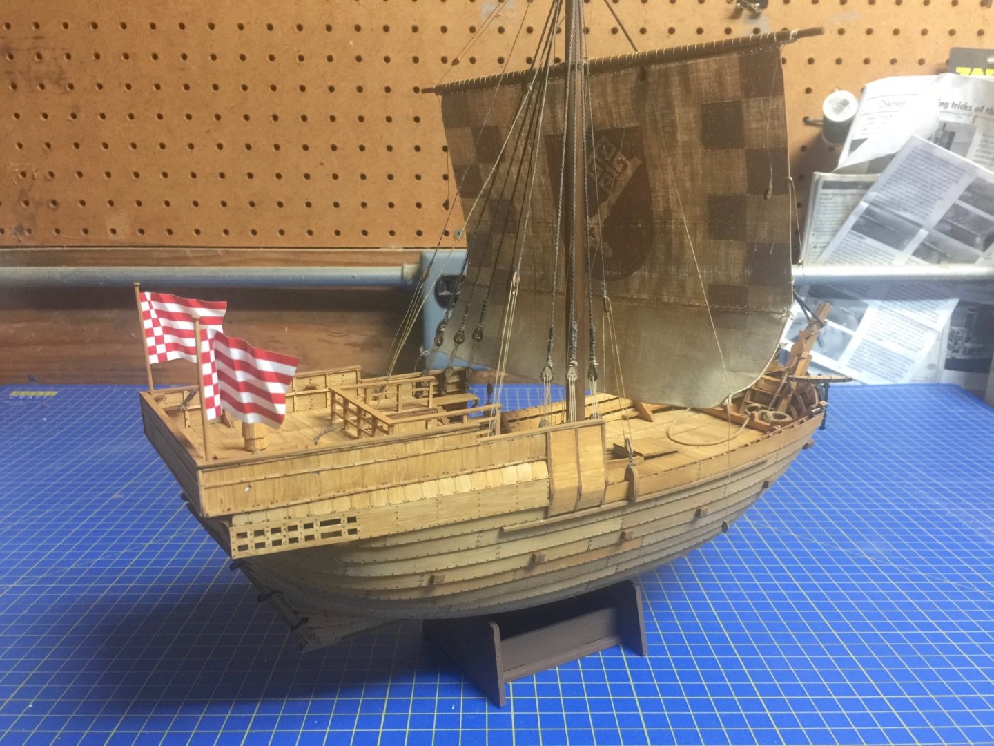
I added most of the reefing points on the sail yesterday and finished them up today. Also, started a block stropping production. There are three sizes of block in this kit, all laser-cut from card stock. Lastly, I added the shrouds, and I'm now adding the upper deadeyes. I don't have any photos of that part yet, but here are some photos of the sail with the reef points going on. This method of attaching reefing points actually has some advantages. It's not difficult to do and since they're glued on, they "hang" perfectly. Threaded reefing points have a tendency to float unrealistically, and you have to treat them with some kind of glue and maybe some ironing to get the correct results.
- 175 replies
-
- 4
-
-
- hanse kogge
- shipyard
- (and 1 more)
-
This seems like a minor update, but switching gears to woodworking and rigging is a milestone for me on this project. Since my last post, I finished making the mast and shaping the yardarm. With the yardarm done, I laced the sail to it. Like lacing the bonnet to the main sail, it took a little while. But, the results were good and I'm happy with how it went. I'm now preparing the rigging line for the next step, which is to add the shrouds to the mast. This includes attaching the shrouds, turning each around a deadeye, and then reeving the lanyards through the deadeyes to secure them into place. Of course, I need to have the mast in place to add the shrouds, so that is now all set. You can see the model rigged with a temporary forestay, which is to help in the tensioning of the shroud lanyards. Looks like I'm also ready to add the reefing points to the sail. The kit instructions simplify this task a bit by attaching separate pieces of riggign line to both sides of the sail. I don't know that this is actually easier or better than just using a sewing needle to poke holes in the sail and threading the reefing points through them, but I'm happy to try out the method that's shown in the instructions.
- 175 replies
-
- 3
-
-
- hanse kogge
- shipyard
- (and 1 more)
-
Hey Chuck, Don't know how it is on the wooden kit, but on the card kit, don't add the rudder until the build is done. The straps are just too delicate and any small bump can knock the rudder loose and tear out hinges. My rudder has taken quite a beating 🤨
- 130 replies
-
- 1
-
-
- wütender hund
- hanseatic
- (and 2 more)