

molasses
-
Posts
455 -
Joined
-
Last visited
Content Type
Profiles
Forums
Gallery
Events
Posts posted by molasses
-
-

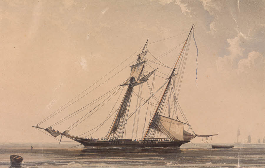
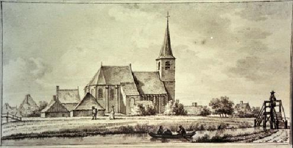
Image is cropped to remove other ships and retouched to remove flags.
-
It's the Gruno.
-
Chuck P mentions here: http://modelshipworld.com/index.php?/topic/918-sources-for-boxwood-blocks/page-2?hl=%2Bblocks+%2Bchuck#entry38771
that he will have boxwood single and double blocks as small as 2 mm in the near future. Perhaps he still has some of his pre-production blocks available.
-
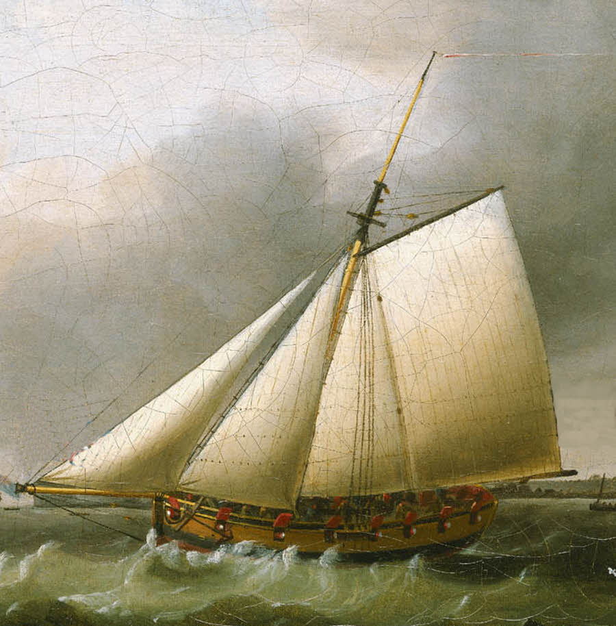
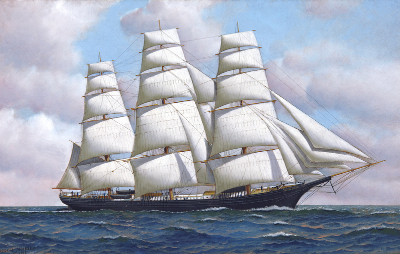
Winner!

Anja is correct! It's the HMS Spider, built at Chatham in 1835. Served primarily on the South America station until 1855. She was the last design (as near as I can tell) by Sir Robert Seppings. I like her because she looks like she's doing ten knots just sitting at anchor.
Easy enough to find on the NMM website: look in the "Fine Art" collection, do a search for "schooner", then look at the images.
With the name you can find plans for her in the "Ship Plans, Admiralty" collection.
I thought you all might get as bored with Google image races as I do and would like something a little more challenging.
 Now that I've given away my favorite source for images that don't show up on a Google search I have to find a new one.
Your turn Anja.
-
Not a yacht.
-
Not Decatur or Amistad.
With a little more searching on the internet the name of the first ship in that new class of 6 gun Man of War Schooners can be found.
-
Name this ship:
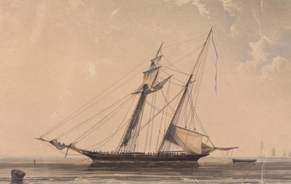
Good luck, you'll need it.

-
SS Nizam
-
Thank you Jay. I would not call myself an expert, I'm a retired welder and occasional machinist who learned something about metals from working with them. My later few years in the industry were in QA/QC (welding inspection).
Based upon your description of the wire in question it does appear that it is some type of basic bronze as you said. I can't think of any inexpensive tests that would tell what it is. As you mentioned, it is stiff and makes good hooks.
I didn't test my presumed copper nickle wire for very long. It could also be nickel plated.
Stainless steels have chromium (above about 10%) which provides most of the corrosion resistance.
On the rails the grayish cast is the oxide coating which conducts electricity as I said in the other post. The oxide on the brass does not which gave model railroaders fits and required constant maintenance until someone hit on using copper nickel rails without increasing the cost significantly. Some model railroaders objected to yellow rails (the fanatics
 ) even after painting them and sanding through the paint on the top of the rails. Painting the rails, removing the paint from the top and leaving the oxide coating on the copper nickel rails was considered more realistic. I was interested in model trains for a while but I found I got bored very quickly running the trains, but I enjoyed the modeling aspect very much, so I went back to building ship models.
 -
Jason:
Unfinished brass elevating screws are very likely correct, based both on the Tricomalee photo and on research I did for my Cruizer class topic (see my signature). On HMS Peacock, my sources specifically mention that her captain had his crew spend much more time keeping the brass elevating screws and brass traversing truck brackets highly polished than he did exercising them at the guns.
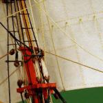
In the Tricomalee photo, the tackle for running out the guns is visible as are the traversing wheels (and the breeching ring you noted). The run-out tackle was hooked into the inboard eyebolt on the slide and at the bulwark near the breech rope eyebolt. Carronades would also have training tackle hooked into an eyebolt at the inboard end of the skid and at an eyebolt set at the midpoint between each pair of gun ports. Here's a detail of an American 32 pounder carronade of the period. I doubt very much that British carronade carriage assemblies would have been much different.
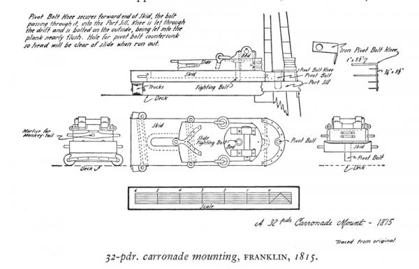
Detail from The History of the American Sailing Navy by Howard I. Chapelle, copyright 1949
You can see from this detail that Caldercraft simplified the carronade assemblies somewhat, most likely in order to keep things simple enough for the average intermediate-level kit builder to accomplish and to keep the production costs low enough to be able to sell the kit to the intended market.
I hope this helps.
-
Well, I beg your pardon guys if I over simplified. But like I said there are many non technical members on this forum and some may not realize that brass and bronze are not the same thing. For our purposes of modeling ships, bronze is not used very often, but it just so happened that I came across some bronze wire.
I just did not want to go into all those details that a metallurgist would drool over.
I certainly did not intend to cause any offense. I apologize for inadvertently doing so. It was worthwhile for you to post the link to that basic information and the results of the chemical coloring of those different wires.
My intent was to correct the statement that bronze "falls between brass and copper in composition" without stepping on anyone's toes, and to expand a little with examples of where copper alloys were used historically on sailing ships as well as in a few items with which most people are familiar. I also wanted to explain how common brass work hardens and how to anneal it.
I believe that presenting more information, simply as background to provide a more complete picture of the subject, is better than less - and infinitely better than a statement presented as fact that is undeniably false.
I again apologize for causing offense.
Dave
P.S. As a follow-up to your tests, I have some white metal craft wire that I suspect is either solid copper-nickel or copper-nickel plated copper wire. I know it isn't silver or silver plated because the packaging didn't say so and the price didn't reflect it. It doesn't blacken with a selenious acid based product, probably because of the nickel.
-
-
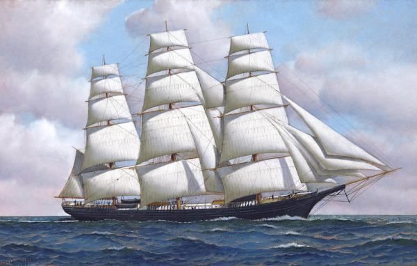
Correct Adrieke. Donald McKay's Flying Cloud set a new record for sailing 'round the Horn in 89 days 21 hours from New York to San Francisco in 1851 on her first voyage. Improved that time by 13 hours in 1853 at a time when the norm for the passage was 200 days. These passages made Captain Josiah Cheesy and his wife Eleanor international celebrities for a while. Mrs. Cheesy was the navigator, something unheard of at that time. The record was not bettered until 1989.
Your turn Adrieke.
-
You guys are incredible
 Most of these you are getting these in 15 - 30 min. I am in awe.
I really isn't that big a deal. Being a life long student of naval history and ships helps, and so does knowing where to look and what to look for; but most important is knowing how to google an image.
 Oops, did I just give away our secret?
Here's the next ship:
-
La Gloire.
-
The link in the first post is bare bones basic. There are literally many thousands of copper alloys, each designed for specific purposes.
The brass sold for hobby use is a 75/25 copper/zinc alloy and it is in the half-hard condition. The brass in firearm cartridge cases is 70/30. Most copper alloys work harden which greatly increases the strength but also makes them more brittle. For example, if you draw annealed (also called "soft" or "dead soft") brass wire through a draw plate you'll have to anneal it after two draws. One draw will render it half-hard. It won't draw a third time, it will usually just break and if not will be so brittle it will break if bent.
Annealing of most copper alloys is done as described by wefalk: heat it until it glows then immediately quench in water. The result of heating until it glows and letting it air cool is very unpredictable. If brass is heated to about 800 F and quenched it will partially anneal to about half-hard.
Navy brass is an alloy of copper, zinc and tin which retains the brass color while also having the higher corrosion resistance of bronze. This is the brass alloy that was used on ships. Muntz metal is a 60/40 copper/zinc alloy with a trace of iron that was frequently used for hull sheathing at a much lower cost than copper after its invention in 1832. See the Cutty Sark website for an example of its use. It looks very similar to brass but a bit whiter.
True bronze contains 8% to 12% tin. Architectural and commercial bronzes are actually brass, with zinc instead of tin, and sometimes also contain lead. That's why modern "bronze" statues turn green while some of the older statues that were cast in true bronze remain the same deep reddish brown they were when cast 200 years ago.
Copper is also alloyed with nickel for high corrosion resistance, especially in seawater; the most widely used for this purpose - Monel - is 45% copper, 55% nickel. Another copper nickel alloy (usually with some zinc) known as German silver contains no silver, but closely resembles it. If you ever had a "silver" ring that turned your finger green it was made of German silver. Nickel silver is a standardized alloy of copper/nickel/zinc (60/20/20, again no silver) used (among many other things) for the rails in model railroading because the oxide that it forms is also white, protects the metal against further oxidation and conducts electricity. It is also used to make most professorial grade white metal musical instruments as opposed to the lower quality yellow brass instruments.
Sorry if I've presented more info than you want or need to know but I spent my entire adult life working with metal and am still fascinated and amazed by what can be done with it.
-
 Welcome aboard! Here's the promised update:
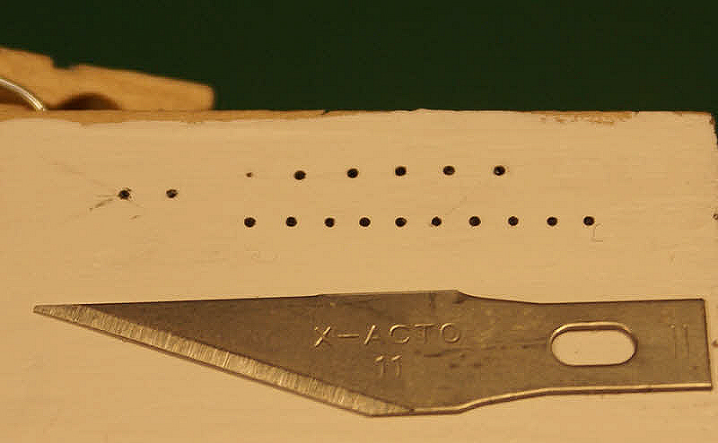
I laid out a row of ten holes (using a gauge for vertical placement and my eyeball for horizontal) with a needle point, checked their vertical placement then enlarged them, again with the needle point. The holes were drilled with a .025 inch drill, then "deburred" with a conical bead reamer. I can't tell you exactly how deep the holes are, I made two complete turns of the drill using only the weight of the pin vise for pressure. I prepared a small quantity of paint, picked up a tiny drop of it on the tip of the wire and transferred it into the shallow hole. Some holes required two dips, I'll take care of that by mixing the paint a bit thicker when I do them on the model. Here's the result - top row was done yesterday, bottom row was done today:
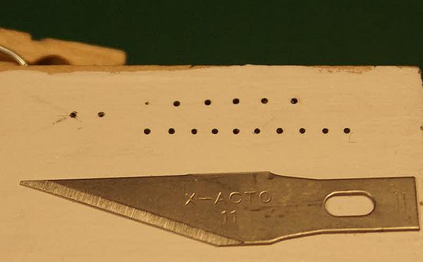
It looks like it will take two to three hours to do 130+ port lights, not counting breaks to rest my eyes. But not today - too little sleep last night and too much caffeine this morning have left me shakier than normal - so I'll work on some other part of the build.
Thank you to those who made suggestions for doing the port lights. All of them were helpful.
Dave
-
Michael and Carl, it appears that great minds think alike.

My test was similar to both your suggestions and it looks like we've solved the problem. I need to test a bit more tomorrow for ease of repeatability, get an idea of how much time it will take to do 130+ dots and refine the technique a bit to speed it up - I did eight dots earlier today and the last five came out perfect at about two minutes each.
In short, I drilled very shallow holes .025 inch (.64 mm) in diameter and used a piece of .010 inch wire to pick up a tiny drop of paint and put it in the hole.
I'll post a report sometime tomorrow with photo(s) and more details on the process.
Dave
-
Thank you for thinking about by problem, Bob, I appreciate it very much. You have a good eye for detail. you saw that the port lights (or port holes, if you prefer) appear to be close to the same diameter as the handrail spacing. The fixture idea seems useful, I may be able to use a variation on it.
I'm not the least bit concerned about the detail around the port lights. They work out at scale to be less than .0005 inch (about the thickness of a coat of paint) above the surface of the hull and don't show in any photo reasonably close to the size of the model. They barely show at even ten times that size and I think I can see them only because I know they're there.
It's just getting all those little dark grey dots uniformly sized and placed that presents the problem. Even on my steadiest day I know free-hand painted dots are not possible; three or four at most, but not 30+ in a row. Perhaps I can uniformly glue small discs with a slow set glue but I would need to glue them to the wood, not the paint, if I want them to stay on when I insert the model in the bottle.
That thought process - and much more - led me to an idea this morning, based on suggestions I received here, and I'm preparing a test piece to try it and a couple variations.
You have "Every build is a learning experience," in your signature. Ain't it the truth!
-
Thanks for looking in, Carl and Bob, and for your suggestions. I've looked in on your builds, admire your workmanship and value your comments.
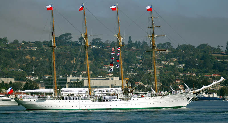
Here's another photo of Esmeralda I'm using for reference to give a better idea of what I need to do with the port lights. I know how easy it is to lose perspective on what is being done after looking at a series of close-up photos; I do it myself after spending several hours working on details through an OptiVisor and a hand held magnifier.
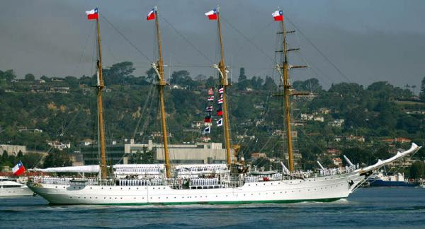
On my laptop display this image is slightly smaller than my model (clicking on the image will bring up a larger one). The model is 3.5 inches x 7 inches (89 mm x 178 mm) waterline to mast heads and fantail to tip of bowsprit. The photo shows why I can't leave off the port lights, how many there are and, in general, the scope of the difficulty of doing them. As you can see they aren't evenly spaced but they are uniformly parallel to the shear line. The port holes can be off horizontally a few thousandths of an inch and no one would notice, but if they vary the same amount vertically they all will look sloppy.
I value suggestions very much. Even if a suggestion seems stupid it may trigger a better idea that will solve the problem.
Thanks again for looking in.
-
Thank you, Michael, for the compliment and suggestion.
I must admit I'm as amazed as you are at the hand rails. Six months ago I considered making them out of the question, but I really had no choice if the model was to be a "model" and not just a representation. Even if the fabricated rails are a failure (they may be too delicate to even handle at installation) I still have the PE rails as back-up. I have to try. They're turning into a mini-project on their own.
-
it is amazing what the camera sees that I don't.
I agree, I catch all kinds of errors in my photos that I don't see even with an OptiVisor.
I agree with Daniel, where's the bottle?
Beautiful work!
-
Thank you for the compliment and suggestions, Daniel, they are appreciated.
I "stole" the basic method of doing the handrails from you when you made inclined ladders out of thread for your Santa Maria, so thank you for that, too.
-
Welcome back!
I've been working out how to do two details that I originally did not intend to do but later decided I can't leave out because they are too prominent - handrails and port holes. Here's a portion of one of the photos I've been working with for the deck details.
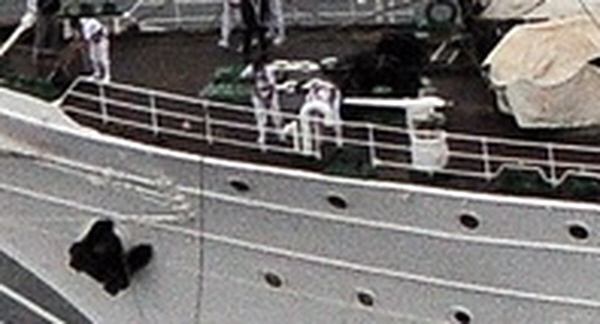
I needed to make the hand rail (which goes around most of the deck perimeter), anchors, four salute guns and four inclined ladders that go in the "waist" amidship (not shown). I found photo-etch (PE) sheets for all of these in 1/600 scale. I also need to do more than 130 of those port holes.
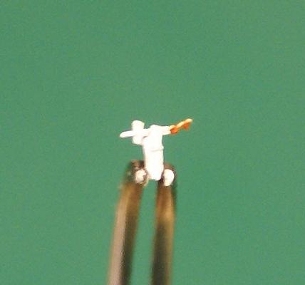
One of four salute guns.
I have a walk-through video of Esmeralda that shows the brown stocks on the salute guns but the stock got "lost" in the cropping, enlargement and enhancement I did to the deck photo; the stock is the same color as the deck.
I had to modify the PE guns slightly so that they looked more like the salute guns. They're made from two PE pieces plus a piece of brass rod for the cylindrical base.
One of four inclined ladders.
Sorry about the fuzzy photos, it seems that I'm at the limits of what I can do with my camera without buying a macro lens.
The ladders were one flat piece that required bending to form the rails, stringers and steps.
I'm pleased with the anchors and they have been installed on the model. Sorry, no photo yet. As with all the PE parts, I glued the two pieces for each anchor with CA and painted them. Before gluing I cleaned the individual pieces (and my tweezers) with acetone and did not handle them with my dirty, oily fingers at any point during the gluing and painting. Cleaned tweezers only. The pieces and completed assemblies are almost too small to handle with fingers anyway.
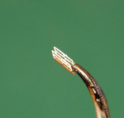
I rejected the PE handrails - the rails and stanchions were too fat - so I decided to make them from the 40 and 45 gauge wire I bought. I chose those two sizes because I need to allow for the thickness of the paint so that the finished rails are close to the correct scale size. I made a square frame from some wood, about 2 inches x 2 inches (50 mm x 50 mm) and wrapped the wire around the frame. The 40 gauge was used for the top rail and the 45 gauge for the other two rails and the stanchions. I'm making about twice as much of the rail as I need so I don't have to go through this process twice when I mess up some of the rail - and I know I will.
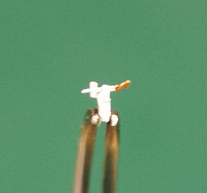
Close-up of the handrails in progress.
The vertical stanchions are at .100 inch (2.5 mm) increments. The horizontal rails are .025 inch (0.6 mm) apart with an increased space between the bottom rail and the top rail below it to allow room to separate them and trim the bottom of the stanchion for installation. There's another set of rails on the other side of the frame. I put a piece of paper in between so I can see, work on and photograph the rails on one side. Without the paper I simply could not focus on what I was doing. It took several hours getting the wire spacing right. The next thing to do is to glue each of the wire intersections while double checking the spacing. I'm experimenting now with which glue to use.
I admit that I'm kind of stumped on how to do the 130+ port holes. They need to be .025 inch (0.6 mm) in diameter. I'm experimenting with several ideas to find out which gives the most repeatable and uniform results and is not too labor intensive. I'm open to suggestions.
Edit to post slightly better photos
- JesseLee, IgorSky and themadchemist
-
 3
3


Name the Ship Game
in Nautical/Naval History
Posted
Not HMS Sloop.