


Bob Cleek
-
Posts
3,374 -
Joined
-
Last visited
Content Type
Profiles
Forums
Gallery
Events
Everything posted by Bob Cleek
-
Masking tape lifting
Bob Cleek replied to Jeff5115's topic in Painting, finishing and weathering products and techniques
I'll throw in one more technique pointer I learned from a professional painter. Be very careful to keep your roll of tape from laying down on any surface which is not dust-free. Easiest way to accomplish this is by habitually storing all your opened packages of tape in a zip lock plastic bag. (This will also keep the tape fresher. The adhesive won't dry out over time.) If a roll of tape is laid on a dusty surface (like a bench top right after sanding,) the adhesive on the edge of the roll will pick up all the dust and grit. It may not be visually apparent, but it's there. When the tape is applied, that dust and dirt ends up right on the edge of your tape and often gets under the very edge of the tape. This promotes paint bleeding beneath the edge of the tape and makes getting a sharp clean edge when the tape is taken up much more difficult to achieve. I second Keith's endorsement of 3M tapes. Cheap masking tape is penny-wise and pound-foolish. Regular blue painter's tape, even 3M, isn't really made for getting perfect masked edges at fine scale viewing distances. (It's made for house painting.) For razor sharp lines on models and a less aggressive adhesive that doesn't lift paint so readily, I'd stick to 3M or Scotch "Fine Line" tape (from the automotive paint supply store) which comes in a range of tape widths down to 1/4", or Tamiya's model tape, which I believe is pretty much the same thing packaged in a smaller quantity at a higher price. These tapes are specially designed to produce perfectly sharp paint edges on curved surfaces and are made of thin material that minimizes raised paint line edges. They'll cost a bit more more, but if you keep the roll in a plastic bag, it should last for years. -
Dominoff Serving machine
Bob Cleek replied to Don Quixote's topic in Modeling tools and Workshop Equipment
I noted that Aleksei Domanov recently moved from Belarus to Poland. I don't know what his reasons for moving to Poland were, but it would appear to be a plus for modelers in Europe and the Americas. From our perspective, Poland is definitely the more favorable environment for an international mail-order business because Poland is part of the European Union and Belarus is not. -
Was Howard I. Chapelle Controversial
Bob Cleek replied to SaltyNinja's topic in Nautical/Naval History
It has nothing at all to do with Howard Chapelle. It was just a follow-up to your insightful "segue" comment that " Too many manufactures of kits grab a concept (no matter how wrong it is) and make a product. That product then becomes what many buyers will believe was the real thing." Sometimes thread-drift leads to unexpected flashes of brilliance. And sometimes not. In this instance, I thought your observation was spot on. -
Was Howard I. Chapelle Controversial
Bob Cleek replied to SaltyNinja's topic in Nautical/Naval History
Would it be a valuable service to create, post, and maintain such a list so that modelers could be encouraged to avoid purchasing such kits? Perhaps add "lack of accuracy" warnings to the forum kit database if it comes to pass. It certainly makes sense to ostracize counterfeit ship kits. Are kits of "counterfeit" ships all that much different? -
Was Howard I. Chapelle Controversial
Bob Cleek replied to SaltyNinja's topic in Nautical/Naval History
SaltyNinja, considering your interest in West Coast fishing boats, you may want to contact someone at the San Francisco Model Yacht Club .(https://sfmyc.org/) There are a number of radio-control modelers there who have built a miniature fleet of Monterey fishing boats: -
An elegant model. Well done! Thanks for sharing it.
- 81 replies
-
- 1
-

-
- Bluejacket Shipcrafters
- Yankee Hero
- (and 1 more)
-
Was Howard I. Chapelle Controversial
Bob Cleek replied to SaltyNinja's topic in Nautical/Naval History
While Howard I. Chapelle wrote in an era when his position as an academic author and employee of the Smithsonian was accorded the respect it deserved, he was nonetheless quite controversial in some matters. The controversy for which he is most famous had to do with his correct assessment that the USS Constellation of 1797 and the USS Constellation of 1854 were entirely distinct ships, a dispute which festered for some time between Boston, with USS Constitution and Baltimore with USS Constellation, which promoters argued was one and the same with the 1797 frigate which had actually been broken up in 1853, the USS Constellation of 1854, built a year later, being the original Constellation's replacement. Chapelle's drawings have been criticized for inaccuracies and a penchant for his substituting information when such was lacking. Given the nature of the work he was doing, and particularly the work of others he was directing during the WPA Historic American Merchant Marine Survey, these being out of work architects, engineers, and draftsmen who were not always conversant with naval architecture and marine engineering, those inaccuracies are understandable and not "controversial." Nobody disputes them. Chapelle's writing style may seem pedantic, "harshly judgmental, and/or "arrogant," to today's reader, but at the risk of being accused of the same (as has happened before ) Chapelle's prose style was entirely appropriate in its time. It is only fairly recently that an ethic of "political correctness" has our diluted our academic literary style, resulting in what one might call the "Little League Syndrome" where "everybody wins a prize," and God help anybody who's heard to say that the losing team lost because they played poorly! What today's readers would consider arrogance in dismissing the work of a predecessor with the comment that they "were not educated" was taken as an authoritative assessment by Chapelle at the time of its writing. Chapelle wasn't alone in his forthrightness and candor. Most commentators of the time were similarly unrestrained in their criticism when they found cause to express it. L.F. Herreshoff was famous for his curmudgeonly, and often quire humorous, prose on the subject of yachts and yachting. In Chapelle's day, the uneducated would never have disputed the pronouncements of the educated, affording them the respect due their degrees, but not so today when "everybody has a right to their own opinion" and the internet provides a platform for hucksters and snake oil salesmen to peddle their wares to the gullible and most feel socially constrained to stand mute when confronted with stupidity. You can get a good sense of Chapelle's "straight from the shoulder" style from his articles Ship Models That Should be Built (Nautical Research Guild - Article - Ship Models that Ought to be Built (thenrg.org) and Ship Models That Should Not be Built, (Nautical Research Guild - Article - Ship Models that Should Not be Built (thenrg.org) which are available in the forum's "Articles Database" (under "More" in the top of the page menu.) Just imagine what sort of reception you'd get in this forum if you expressed Chapelle's opinion that: "There are enough Flying Clouds, Constitutions, racing fishermen, and imaginary galleons God knows, and there is surely some type of boat or vessel that will interest a modeler that has not yet been modeled. But, if you are not interested in accurate models and desire to build stuff of a level of truthfulness of a Hollywood movie "Pirate Ship" or "Spanish Galleon" forget I brought the matter up." They'd scratch your eyes out for sure.- 17 replies
-
- 15
-
-

-
Looking for a good "starter" pin vise set
Bob Cleek replied to Capella's topic in Modeling tools and Workshop Equipment
You're right because you've correctly determined a $20 pin vise has the ability to do the work you want it to do. I'd expect this is true of most ship modelers and certainly of those starting out. This fact is a good example of why the maxim that one should always buy the best tool they can afford has to be tempered by common sense. As far as I can see, what hasn't been mentioned in this thread is what difference there is between the low-priced pin vises and the high-priced ones. The determining factor is the level of accuracy to which each is capable. For most ship modeling tasks, however, we aren't talking about the sort of accuracy a fine watchmaker or scientific instrument maker requires, but rather the sort of accuracy a wooden ship modeler requires. A pin vise's accuracy comes from the pin vise's ability to hold a bit (or any other cylindrical piece) of a given diameter in perfect alignment with the vise shaft itself. The less expensive, and less accurate pin vises are just less reliable in their ability to grasp and hold a bit shaft in perfect alignment with the vise body. If a pin vise is twisted by hand, within the tolerance limits of a wooden ship model, the "runout," as machinists call it, i.e. the amount of "out of true" the bit point will rotate at, is not particularly problematic. On the other hand, if a pin vise is mounted in a drill press, the "whip" from the runout can often cause a bit to break. What the buyer gets for their $100 when buying a top-end professional grade pin vise like a Starrett or Moody is the certainty that the costly close-tolerance machining in the expensive pin vise ensures negligible runout at the tip of the drill bit and consequently drills holes to very high tolerances. Another bit of important information not mentioned is that a four-jaw (or more) collet holds a bit with much more accuracy than does a three- or four-jaw chuck. Collets are made to hold specifically sized cylindrical shapes. While there's some range of "play" in inexpensive collets, machinists' collects are made to fit specific diameters so that when the collet holder cap is tightened down the collet evenly grasps the cylinder all around its circumference, ensuring secure holding with negligible runout. Chucks only hold cylinders by applying pressure at points equal to their number of jaws and are consequently more prone to runout. Here again, precision machining in a chuck's manufacture determines the price of a given chuck at a given accuracy tolerance level. Inexpensive chucks simply do not ensure accuracy to tight tolerances. While those who own them are probably already aware, it might be noted that the style of pin vise made by General and, I believe others, and pictured in posts #9 and #11 above actually contains two double-ended differently-sized collets. The collet holder cap nut permits the double-ended collet it holds to be removed and end-for-ended. The second double-ended collet is stored in the shaft of the pin vise, which unscrews to permit access to it. I mention this because I owned one of these General-style pin vises for decades without realizing there was another double ended collet stored in the shaft of the vise handle!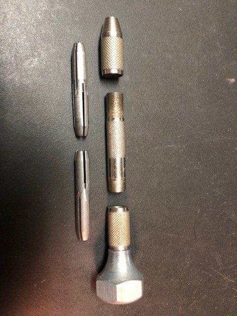
-
Masts and the use of power tools
Bob Cleek replied to DaveBaxt's topic in Masting, rigging and sails
There's no miter gauge required at all. It's a "rip taper gauge." Here's a photo of the rip taper gauge made by Byrnes Model Machines and sized for their 4" table saw: Byrnes Model Machines - Table Saw This one is adjustable for the angle of the taper desired, but a wedge of plywood cut to the desired angle will serve as well to cut a single angle. alternately, a rip taper gauge is easily made in the shop from scrap wood. As pictured, with the "straight" leg of the rip taper gauge against the fence, the work piece is slid down the angled side of the rip taper gauge as if the angled leg of the gauge were the fence and the taper is cut in that fashion.
-
Tage Frid Teaches Woodworking: Three Step-by-Step Guidebooks to Essential Woodworking Techniques. Book 1: "Joinery," Book 2: "Shaping, Veneering, Finishing," and ""Book 3: "Furniture making," In print for probably close to 40 years now, this is considered by some the Bible on classic hand tool woodworking. Originally three separate volumes published by Fine Woodworking, and then in a three volume slip-cased set by Taunton Press. Written by the late Tage Frid, a traditionally trained Danish-born woodworker who was a big player in the American custom art furniture movement. Nearly everything in Frid's books translates easily to modeling because he covers well the basics of traditional woodworking hand tools. Modern power woodworking tools are covered, as well. Profusely illustrated. A recognized primary reference work on the subject. Tage Frid Teaches Woodworking: Three Step-by-Step Guidebooks to Essential Woodworking Techniques: Frid, Tage: 9781561588268: Amazon.com: Books It's also available in online in PDF format: [pdf] Download Tage Frid Teaches Woodworking Ebook and Read Online (saintlukebc.org)
-
I have a Vanda-Lay drill press, acquired used for the same reason Cleat got his. It works fine. I wish I had the Acra-mill set up, which includes a drill press function, but with so much more, particularly the X-Y table. Being powered by a Dremel Mototool, it's capacity is limited, but working with wood, it's more than adequate and much better than the similar drill press made by Dremel. Note that Vanda-Lay can provide on special order 1" ID clamps for holding a 1" Foredom handpiece instead of the Dremel Mototool. (A crafty machinist would have no problem turning out a shop-made set from aluminum sheet stock.) I don't have the clamps for the Foredom handpiece, but will probably get around to it one of these days. That would give me the added power of the Foredom tool and the foot pedal speed control with good low speed torque, which, of course, is the major weakness of the Dremel Mototool. (I've been meaning to make a similar clamp holder so I can mount my Foredom handpieces on the cross-slide of my 12"X42" Atlas/Craftsman lathe.)
-
Have you contacted the designers, Sparkman and Stephens: Sparkman & Stephens (sparkmanstephens.com) and the Lightning Class Association: Home - International Lightning Class Association ? The class association appears to sell plans on their website. The Woodenboat Store sells a sailing pond model Lightning kit: Lightning Model Kit – The WoodenBoat Store There are bits and pieces of Lightning plans all over the internet. They look to be "dory built," so any table of offsets for these hard-chined flat-sided boats and dimensions wouldn't be much. You can pretty much get all you need for modeling purposes from this drawing, although you'll have to take the measurements from the baseline at each frame to generate the curve of the plank keel and enlarge the drawing to trace the shape of the rudder and stem. There's a bit of a curve to the floors, as well which is easy enough to gauge. Aside from that, it's all straight stuff.
-
Working out the correct height of the masts from the Deck
Bob Cleek replied to DaveBaxt's topic in Masting, rigging and sails
I suppose it depends on who's measuring the mast. Generally, shipyard terminology would include the length of the mast between the partners and the step, since the yard has to build a mast that long. Height above the partners, or the waterline for that matter (for navigational purposes), are usually designated as such. Since you are building a model of H.M.S. Endeavour, I expect there are plans readily available to answer your question. If your mizzen looks lower than the many pictorial representations available, it's probably too short, no? That the angle of the shrouds causes them to fail to clear the cap rails certainly seems to suggest the hounds are too low. Here's a couple of contemporary paintings of H.M.S. Endeavour. You be the judge: By Samuel Atkins (c.1760-1810) - National Library of Australia, nla.pic-an5921609, Public Domain, https://commons.wikimedia.org/w/index.php?curid=7458795 By Thomas Luny - http://nla.gov.au/nla.pic-an2280897, Public Domain, https://commons.wikimedia.org/w/index.php?curid=7351149 -
Marring the wood is a function of how soft the wood is and how hard the jaws of the clamp holding it are tightened. Denting can be prevented by placing a weight-distribution pad beneath the clamp jaws. This might be a scrap of wood or plastic. Even a piece of an old credit card or even matchbook cardboard. That said, if you have to tighten a clamp so much that any of the usual planking wood species would be dented, you have one or more of three interrelated problems: 1) You are clamping too hard and/or 2) your plank is not properly bent before gluing and/or 3) you are using the wrong species of wood (e.g. balsa or other soft wood.) Number 2 is probably where the greatest problem lies. Planking should be spiled and cut or bent to shape using heat (from a planking iron or a small clothes iron) such that the plank fits perfectly on the frames or bulkheads without requiring any significant tension to bend it into place. This is a "perfect world" goal, but, in any event, the plank should be pre-bent to shape to the point where very little, if any, clamping tension is required to pull it into place. The frames or bulkheads are not intended to serve the purpose of forming the shape of the planking under tension. The solution to the problem addressed here isn't sourcing suitable clamps on the retail market, but rather shaping your planks correctly before you glue them in place. Read the "Planking Downloads and Tutorials and Videos" section in the "More" drop-down menu at the top of the forum page: Planking Downloads and Tutorials and Videos - Model Ship World™ These essential tutorials teach the basic techniques and skills for plank-on-frame modeling which are unfortunately too frequently omitted from kit instructions and consequently pose a stumbling block for beginning modelers. If you are struggling with clamping planks, you are doing it the hard way and creating a lot of grief for yourself. Planking correctly is a much more enjoyable task than what you've apparently been experiencing.
-
Welcome! It appears you have the mind set which is the prerequisite for success, success being the enjoyment of the process of the incremental acquisition of skill and experience. Rome wasn't built in a day and neither are good ship models. It all begins when you start. If one commits themselves to doing the common things uncommonly well, one step at a time, you'll do just fine.
-
Yes, the English foot and the Imperial foot are the same length at 304.8 millimeters.Not my knowledge on this, but Wikipedia provides metric equivalent tables for pre-1826 English measurements and post-1826 Imperial measurements at: English units: https://en.wikipedia.org/wiki/English_units Imperial units: https://en.wikipedia.org/wiki/Imperial_units
-
This is true, however, it seems problems often arise when researching the identity of vessels by comparison of unidentified contemporary models with plans, customs office registrations, and other contemporary documentation. Differences of several feet in overall length, depth, and breadth are quite common.
-
For those bent on accuracy, don't forget that a "foot" varies from time to time, nation to nation, and trade to trade, in too many ways to count. I believe that the confusion over various reported measurements of old ships is not infrequently the result of different measurement standards. Even different cities had different "feet." Before the metric standardization, a foot in Belgium could be no less than one of eleven different "feet," depending on the town: Ypers was 273.9 mm, Bruges was 274.3 mm, Brussels was 275.75, Antwerp was 286.8, and so on. In Venice a foot was 347.73 mm. Twenty-one different "feet" were used in Germany and five in France. Similarly, there were nine different Dutch feet depending on the town and a foot was 296.9 mm in Sweden and 313.75 in Norway. Adding up the differences over the length of a sizeable vessel can result in significant differences overall between differing foot-standards. There's quite an extensive list of Imperial to metric local and historical equivalents at: Foot (unit) - Wikipedia One of the most maddening exercises I've encountered in marine plans were the set of 1936 English builder's plans for a famous yacht which were drawn to a scale of 1" to 12.5". It took some detective work to unravel why a respected naval architect would use a scale nobody'd ever heard of before. It turned out the plans were drawn for use by a Swedish yard contracted to build the vessel. By drawing to a 1"=12.5" scale, the yard could use all of its Swedish measuring tools when working with the plans!
-
The nomenclature here is really confusing. First, the applicable period has to be defined. A hole attached to or worked into a sail or other piece of canvas to attach a line is called a "cringle." In earliest times, cringles were made by sewing a rope "grommet" around the hole in the canvas. A rope grommet is made up of a single strand of unlayed rope laid around itself to produce a three-strand circle with only two loose ends worked back into the circle. In later times, a metal ring might replace the rope grommet. The cringle could be worked into the canvas without any additional reinforcement... or additional secondary cringles could be added in order to spread the forces over a wider area of the weaker canvas and, later still, a metal grommet with hammered flared edges might be inserted in the finished cringle to provide extra strength and chafe protection. Much later, I'd expect beginning sometime in the 19th Century, but I'm just guessing, harder manufactured metal grommets were used. These required less handwork for the sailmaker to install. Later still, so-called "English grommets,' two piece grommets installed with a patent press, were also used, as in the secondary holes in the below picture. Modernly, synthetic webbing machine-stitched into the canvas which secures a metal ring has become a simple approach, as are sophisticated grommets pressed into place with high-compression equipment. So, the period of the model sail will dictate whether the cringle is made with a rope grommet or an metal one. At smaller scales, a dark-colored dot with the line passed through with thread on a needle should be enough.
-
I'll buy that. Untarred hemp rope is still made. I've handled some hemp buds that were pretty sticky, too. I believe, however, that we are in agreement, actually. As you say, "This rope is called "white rope" in opposition to the tarred rope which is dark. This white rope is obviously not white but straw colored as it has been said." It's a linguistic difference, I think. The hemp used to make marine rope was generally run through a bath of thinned pine tar before it was laid up on the rope walk. This resulted in its color being exactly as you describe, "straw colored." Hemp rope that is used for standing rigging is coated with thick pine tar in use to preserve it. This tar coating is reapplied about every six months and soon results in a very dark, virtually black, color. So, to put a finer point on it, the fibers are run through a thinned hot tar bath before the rope is made and this results in the "straw colored" rope. When that straw colored rope, which was called "white rope" by the French, was tarred by applying thick tar to it, it became "dark rope." Hemp rope that has not been treated with pine tar before being laid up looks white, like this:
-
I know next to nothing about the period Mediterranean vella Latina vessels mentioned, but I do think, perhaps, though I'm not positive, that you may be confusing hemp and flax rope in distinguishing between "white" and "tarred rope. I'm not sure there was ever a distinction between "white" (untarred) rope and "tarred rope" in the way you are explaining. I've always understood that all "working rope" (as opposed to ornamental rope) was lightly tarred in the manufacturing process for the purpose of providing resistance to weathering. I believe hemp rope is stronger than flax (linen) rope because it can be given a harder twist and being oiled doesn't enter into it, but I could be wrong. It wouldn't be the first time.
-
There are different grades of quality pine tar, generally a function of the processing and resultant purity, but generally speaking, pine tar is pine tar. (e.g. There is a pharmaceutical grade of pine tar produced for medical applications.) The consistency of tar varies in accordance with the particular application. When applied to standing rigging, It was called "slush." The traditional recipe is one part pine tar, one part raw linseed oil, and turpentine to the desired consistency. Modernly, paint thinner can substitute for turpentine and "boiled" linseed oil can replace the raw linseed oil, which will result in a faster drying time, as will adding a bit of Japan dryer to the raw linseed oil mix. As can be seen from the ingredients, the oil and solvent can be adjusted to modify the consistency of the "slush" so as to work best for the use intended. It's thinned considerably to the consistency of thinned varnish when applied with a brush as a sealing finish on bare wood ashore and afloat. (When used as a finish on bare wood, it's sometimes called "boat sauce" or "boat soup.") It was applied at the consistency of paint when applied to iron fittings and canon as a rust preventative. When applied to cordage when spun in the ropewalk, it was thinned greatly in order to result in a thin coating. On running rigging, it was thickened considerably (hence the term, "slush") and applied with slush-soaked rags wiped on the rigging. The use of thick "slush" on standing rigging avoided much of the drips and splatters that would have occurred using a thinner mix applied with a brush. Pine tar alone was applied to pounded and flayed hemp stalks and rolled into "ropes" to make oakum for caulking seams. Seams were sometimes stopped with tar, heated and poured into the seams with a special spouted can, but that was a very messy proposition, particularly when the decks would be exposed to the hot sun and the tar softened and was tracked everywhere. [Alternately, deck seams were stopped with putty made of litharge (white lead oxide powder,) whiting (powdered chalk) and raw linseed oil or with various bitumen compounds. In the mid-19th Century, "naval" or "marine glue" was invented and remains the best stopping for traditionally planked decks. Jeffreys Marine Glue, now made by Davey and Co., London, is a proprietary compound of bitumen and natural rubber which liquifies when heated and is poured hot into the seams. When cooled, it is not sticky.] Greatly thinned pine tar will have a honey color, but repeated applications will quickly darken the surface as the coats build up and in short order the color is going to be a very dark brown, so much so as to appear virtually black. Because pine tar will soften in the sun and, being black, will "soak up the heat" it softens in sunny hot weather and becomes very sticky, generally creating a huge mess. For this reason, tarred iron fittings and ordinance were often left to "dry" and then painted over with black paint (originally made of turpentine, linseed oil, and lampblack.) Tarring and painting cannon balls prevented their rusting and thereby eliminated tedious hours spent cleaning rust off the balls, a rust-free ball being essential for accuracy at range. I hope this answers some of your questions.
-
Yes, but that really has nothing to do with the subject being discussed. The best anyone can do given your analysis is to build a replica of the ship which was found and it will be accurate only to the degree that the original artifact was intact. Building a replica of one of the Viking grave ships is possible because some were well preserved, as, you note, was Vasa. My point, however, is that one ship doesn't prove a whole lot beyond that one ship. I really don't know how many more "accurate" model kits of Nina, Pinta, and Santa Maria, or Mayflower, Golden Hind, Half Moon, and Noah's Ark will be sold before folks realize we have no historical record of what these vessels actually looked like.
-
Rest assured, we know exactly what "Stockholm" or pine "tar" was, is, and always will be. It was a naval store about which much has been written. Sourcing it required political alliances with nations having pitch pine forests, hence, the Europeans called pine tar "Stockholm tar" simply because Sweden controlled the production of it. Pine tar was the only tar relevant to our discussion. When Britain was unable to secure tar from the Baltic forests, it focused on the colonization of the American Eastern Seaboard for naval stores, primarily shipbuilding timber and pine tar. North Carolina was the center of the British naval pine tar industry and to this day people from North Carolina are called "tar heels." It's not rocket science.
-
Yes, but that really has nothing to do with the subject being discussed. The best anyone can do given your analysis is to build a replica of the ship which was found and it will be accurate only to the degree that the original artifact was intact. Building a replica of one of the Viking grave ships is possible because a few were very well preserved, as, you note, was Vasa. My point, however, is that one ship excavation doesn't prove a whole lot of specifics beyond that one ship. I really don't know how many models of Nina, Pinta, Santa Maria, Mayflower, or Noah's Ark, for that matter, before kit manufacturers admit their kits are just somebody's imaginary interpretation of the real ship.
