Bob Cleek
-
Posts
3,342 -
Joined
-
Last visited


.thumb.jpg.5a33ce11c7bd2c0f448734dd2e7ea95b.jpg)


-
 BenD reacted to a post in a topic:
How to make flat rope coils?
BenD reacted to a post in a topic:
How to make flat rope coils?
-
Keith Black reacted to a post in a topic:
How to make flat rope coils?
-
vossy reacted to a post in a topic:
How to make flat rope coils?
-
 bridgman reacted to a post in a topic:
How to make flat rope coils?
bridgman reacted to a post in a topic:
How to make flat rope coils?
-
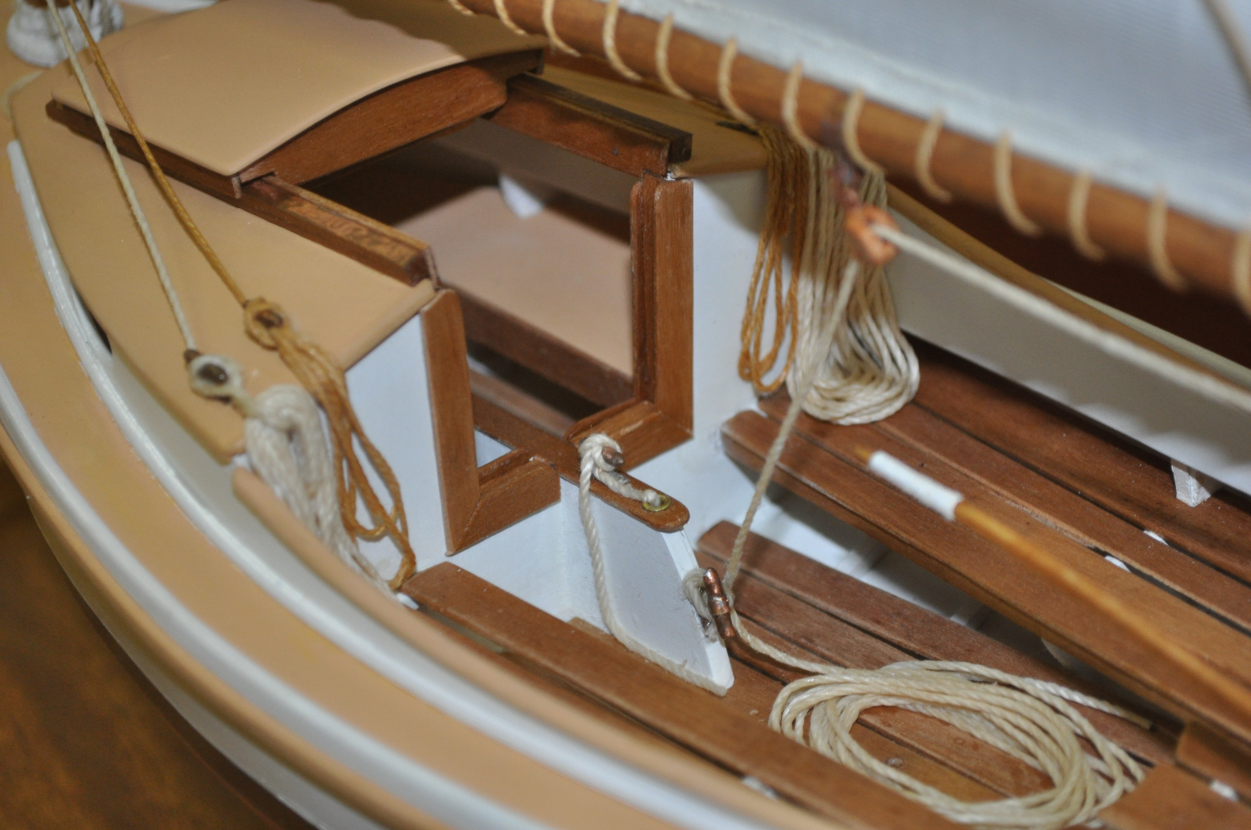
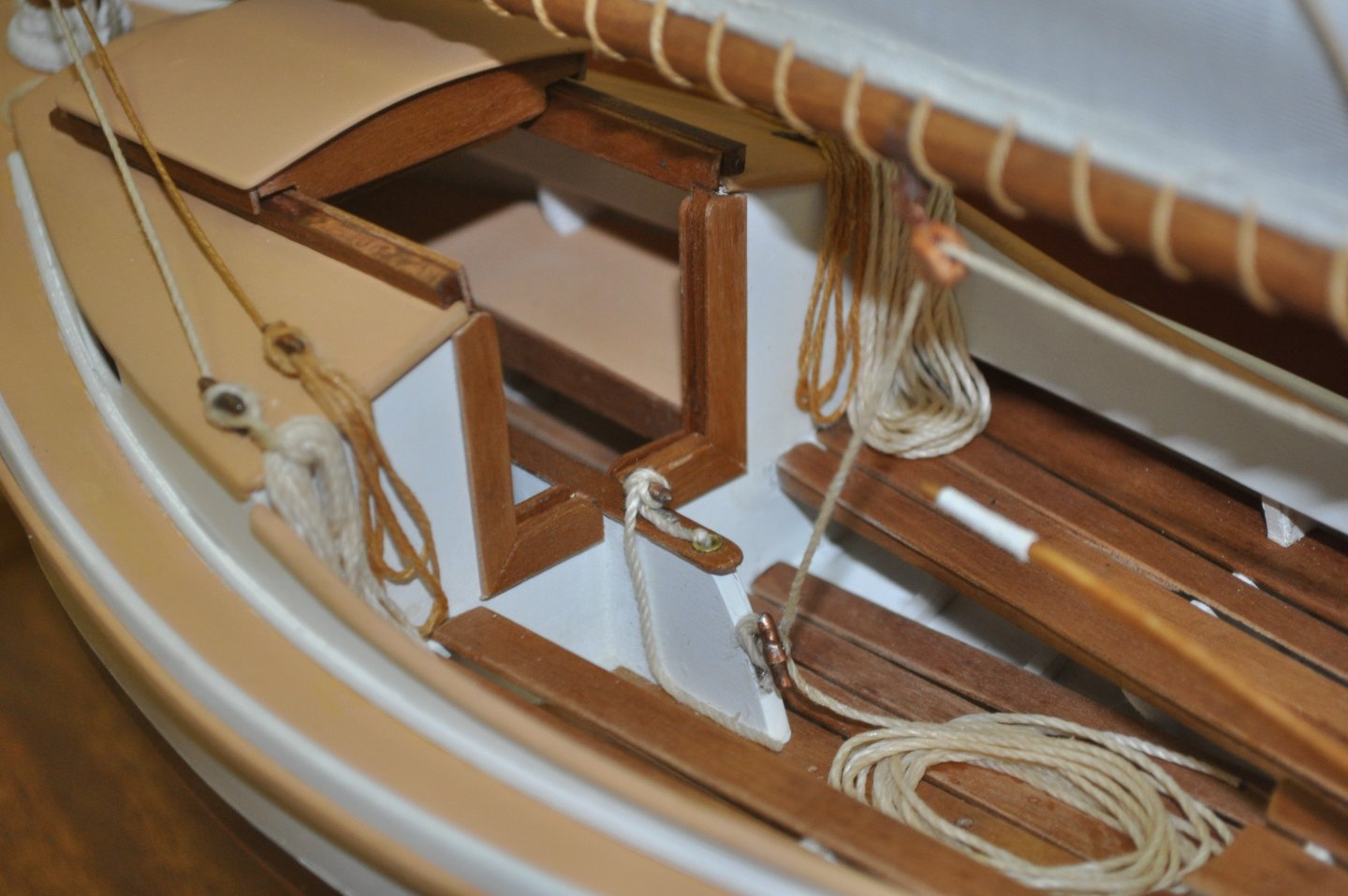
Use canned clear shellac (about a 2 pound cut - Zinsser Bullseye brand or equivalent) to cause the line to stiffen. Shellac is dissolved in alcohol. As the alcohol evaporates, the shellac soaked into the line will begin to harden and the line can be formed into any shape. Once the shellac has dried (within minutes) the line will be stiff and hold whatever shape you have given it. If more working time is needed, simply apply additional alcohol and the shellac will soften again. Results example below. Coils made on a form consisting of map pins placed into a wooden base around which the coils were wound. Coils were installed on the model, softened with alcohol, and formed in place to depict normal hanging behavior of full-size line.
-
Canute reacted to a post in a topic:
Helping hands vice
-
Scottish Guy reacted to a post in a topic:
Helping hands vice
-
Canute reacted to a post in a topic:
Nabopolassar King of Babylon and Daffadar, Skinners Horse by king derelict - Art Girona - 54 mm
-
Canute reacted to a post in a topic:
Nabopolassar King of Babylon and Daffadar, Skinners Horse by king derelict - Art Girona - 54 mm
-
Bob Cleek reacted to a post in a topic:
Helping hands vice
-
DaveBaxt reacted to a post in a topic:
Helping hands vice
-
jpalmer1970 reacted to a post in a topic:
Helping hands vice
-
Bob Cleek reacted to a post in a topic:
Nabopolassar King of Babylon and Daffadar, Skinners Horse by king derelict - Art Girona - 54 mm
-
QuadHands are "finestkind." You'll love them. Nobody should waste their money on those near useless ball-jointed "helping hands" that you have to adjust by tightening wing-nuts. They are really junk. (And, like so many others years ago, I bought one, too! ) One thing to be careful about, though, is to make sure you buy the real QuadHands fixtures. There are "carbon copy" Chinese knockoffs all over the internet, but they aren't the same quality at all. The QuadHands uses high quality alligator clips for one thing. Cheap alligator clips are a dime a dozen, and they don't hold well at all. Don't subsidize intellectual property theft. Buy the real McCoy!
-
Bob Cleek reacted to a post in a topic:
Helping hands vice
-
Sorry about that. I got interrupted writing the above post. In the meantime, it looks like you "pulled the pin" and ordered a vise from Micro-Mark when you could have ordered it from Walmart for ten bucks less. I won't rub it in, but only to say that it always pays to shop around before buying anything from Micro-Mark.
-
An excellent tool that everybody should have. However, you should shop around on the internet to find the lowest price. As usual, Micro=Mark has more tools for modeling than most any catalog, but nearly always at a considerably higher price. For example, see: Universal Work Holder Peg Clamp Jewelers Engraving Hand Tool for Jewelry Making - Walmart.com This tool has a handle that can be screwed off and the base neck is hexagonally shaped so it can be placed in a bench vise. That's often a more convenient way to use it than holding it in one hand and some tool or paintbrush in the other. Fancy articulated bench top holders are made for it, or sold with this vise, but all are of questionable utility (often too weak) and overpriced. The best option is to buy a decent small 2.5" or 3" bench vise with a clamping attachment for $30 or less. E.g.; $23.50 Clamp-On Swivel Vise - Lee Valley Tools Another option that is very handy to have is one of the extremely versatile QuadHands holding platforms. These are heavy iron plates with flexible arms holding heavy duty alligator clips that attach to the base plate with rare earth magnets. Sold on Amazon and elsewhere. They are really useful for lots of applications, particularly holding parts for painting, gluing, and soldering. This is a commercial grade tool made for and marketed to the electronics assembly industry. Beware of identical-appearing Chinese knock-offs. The quality is not the same. "QuadHands" is the brand you want. See: QuadHands® - Helping Hands Tool They come in several sizes and additional "arms" and attachments are available, starting at around $40. Also sold on Amazon.
-
Bob Cleek reacted to a post in a topic:
Reef line length...
-
Bob Cleek reacted to a post in a topic:
Reef line length...
-
You might want to reconsider the above. In practice, it appears that reef points on any given sail would all be of the same length in any event. The "rule of thumb" from Falconer's above sounds right, but here again the maxim, "Different ships, different long splices." applies. The reef points need to be long enough to conveniently encircle the mass of gathered canvas in the sail to be secured. Therefore, the size of the sail is the determining factor. In different periods, the common square sail sizes varied. In later times, particularly with merchant vessels, the size of the sails was reduced to permit easier handling and, thus, smaller crews, which meant more profit in the operation of the vessel. Obviously, a longer square sail will require longer reef points than a sail that's half as long. Naval vessels would furl sails very tightly such that the sail gathered and tied on the spar would not exceed the diameter of the spar. On the other hand, a merchant vessel would characteristically be less fastidiously maintained, and sails might be furled less tightly, if not just making a sloppy job of it sufficient only to get the canvas under control and out of the way and so might have longer reef points. Not to make you crazy or anything, but depending upon the scale you're working in and the level of detail you are depicting, note also that reef "points" were so called because they were "pointed" by working a taper into their ends. There were general standards for the length of the reef points. (Note the term "reef points" references the pointed shape of these lines. It does not have anything to do with the gromets worked into the sail through which reef points are passed, as is modernly a commonly heard misuse of the term.) A bit of research in the appropriate sources for the period of your model will answer your questions much more specifically. For example, see "Steele's" for both the Admiralty and merchant marine practice circa 1794: https://maritime.org/doc/steel/large/pg148.php There you will also see the number of gaskets that are required for each rate of ship (by the number of guns) to tie the completely furled sail to the yard. Illustrations are also provided. For example, excerpts from Steele's: GASKETS. Braided cordage used to confine the sail to the yard, when furled, &c. ARM-GASKETS; those gaskets used at the extremities of yards. BUNT-GASKETS are those used in the middle of yards. QUARTER-GASKETS; those used between the middle and extremities of the yards. GASKETS are made with three-yarn foxes. Those for large ships consist of nine foxes, and those for smaller of seven. Place four foxes together, but lay them of unequal lengths; mark the middle of the whole length, and plait four foxes together, for eight or nine inches; then double it and plait the eight parts together for five inches, and work in the odd fox. The whole is then plaited together for eighteen inches in length; then leave out one fox, and so keep lessening, one fox at a time, till you come to five. If the foxes work out too fast, others must supply their places, till the whole length is worked, which is from five to seven fathoms long. To secure the ends, make a bight, by turning upwards one of the foxes, and plait the others through the bight, then haul tight upon that laid up. (Obviously, few modelers will actually plait their reef points as described by Steele, but an understanding of the full-scale practice better enables the modeler to depict such detail as they may wish secure in the knowledge of what it's supposed to look like.) POINTS, short pieces of braided cordage, plaited together as gaskets are; beginning in the middle with nine foxes, and tapering to five at the ends, and from one fathom and a half to one fathom in length. They are used to reef the courses and topsails. ROPEBANDS differ from gaskets only in their length, being from seven to nine feet long. POINTING. Tapering the end of a rope, or splice, and working over the reduced part a small close netting, with an even number of knittles twisted from the same, to prevent the end untwisting, and to go more easily through a block or hole. REEF. That portion of a sail contained between the head or foot, and a row of eyelet-holes parallel thereto, which portion is taken up to reduce the surface of the sail when the wind increases. Sails, according to their sizes, have from one to four reefs. A BAG-REEF is the fourth, or lower, reef of a topsail. A BALANCE-REEF crosses boom-mainsails diagonally, from the nock to the end of the upper reef-band on the after-leech. When modeling, the best approach is to experiment with a sample of the sail material you'll be using and simply measure how much line it takes to tie the reef lines and let that be your guide for the length of reef lines and gaskets. Many will reduce the model's sail size in order to more easily depict a tightly secured sail on the spar, in which case a similarly sized sail sample will yield the proper length of reef line or gasket needed.
-
Bob Cleek reacted to a post in a topic:
Miniature Russian carving tools
-
Bending hard brass.
Bob Cleek replied to navarcus's topic in Metal Work, Soldering and Metal Fittings
Probably. For a good example of brass skeg fabrication see: -
Bending hard brass.
Bob Cleek replied to navarcus's topic in Metal Work, Soldering and Metal Fittings
It's not about the type of vessel or style of hull. He has as 10" x 1/2" x 1/8" piece of "hard" brass to use as a skeg which he wants to bend in order to make it "3/4" lower at the middle to clear the prop." If the stock is to be a skeg, given it's dimensions, I'd expect he wants to know how to bend it 3/4" across the 1/2" wide vertical face of the skeg. "Hard" brass can easily be annealed with a torch, but there are limits to "bending across the flat" which would seemingly be exceeded in this scenario. -
Bending hard brass.
Bob Cleek replied to navarcus's topic in Metal Work, Soldering and Metal Fittings
I'm sorry. Maybe it's me, but I can't figure out the bend you are contemplating. A picture is worth a thousand words sometimes. I'm not sure how you want to bend it. If you're trying to do what I think you are trying to do, I'd have to answer "No can do." -
Bob Cleek reacted to a post in a topic:
Looking for wooden ship model of Richard Henry Dana's ship, the Brig 'Pilgrim' (Moved and retitled by moderator)
-
Bob Cleek reacted to a post in a topic:
Do I need thes books, or just want them?
-
Bob Cleek reacted to a post in a topic:
Do I need thes books, or just want them?
-
I don't recall the Blairs, so cannot pass on any news about them. Sorry.
-
It's nice to hear of another who remembers Ray Aker, a man who certainly deserved greater fame than he realized during his lifetime. He was a very good maritime historian and one of the better draftsmen around. I still have the copy of his beautiful technical drawing of the remains of the 1840 whaling bark Lydia uncovered during excavations for the 1978 construction of the San Francisco Peripheral Sewer project which he gave us when I knew the archaeological impact report consultants on that project. http://library.mysticseaport.org/ere/odetail.cfm?id_number=1961.72 Without passing any judgment pro or con regarding your posting your research records on the Drake Navigator's Guild's website, as a fellow member of our generation, I would urge you to strongly consider making provision for the donation of your research files to the J. Porter Shaw Library at the San Francisco National Maritime Museum at Fort Mason, San Francisco. As you probably know, the J. Porter Shaw is the best recognized repository for such subject matter these days.
-
Sorry for the confusion. I was in the middle of an edit, so you caught only the beginning of the post. Check out the link I provided above to the U.S. Amazon and eBay websites and you'll see they are both offering new and used copies. Beyond that, I expect the cost of shipping is prohibitive. We keep hearing that in recent times on all sorts of modeling essentials. The cost of an item on the opposite side of the Pond seems to almost double when the shipping is added. We have U.K. books listed on U.S. eBay, so I'm not sure why it doesn't work the same the other way around. Is it possible the "not available" status is a result of some sort of E.U. customs issue?
-
It was an expensive book when first published and seems to have remained so. Apparently, it was until rather recently only available directly from the publisher, Ancre, in Nice, France. The Art of Shipmodeling - Bernard Frolich - Ancre There are now new and used copies available on U.S. Amazon (The Art of Ship modeling: Bernard Frolich: 9782903179847: Amazon.com: Books) and U.S. eBay: (https://www.ebay.com/sch/i.html?_from=R40&_trksid=p2334524.m570.l1313&_nkw=The+Art+of+Shipmodeling+by+Bernard+Frolich&_sacat=0&_odkw=The+Art+of+Shipmodeling&_osacat=0) Believe me, we feel your pain over here, as well. We have to pay the same exorbitant shipping costs from the U.K. to the U.S. that you apparently must in the opposite direction. I believe this increase in shipping costs was attributable to the fact that all shippers seem now to be sending everything air freight. Time was, you could order something from Europe and it might take three or four weeks to get here, but the shipping didn't break the bank unless you wanted to opt for air freight. Now it's all air freight whether you need it or not. On top of that, you may also be paying the price for "Brexit," but I'm not really all that familiar with that issue, of course. Perhaps you might consider having a friend who is making a run to the South of France "smuggle" a copy back for you from Ancre. It's really a valuable resource.
-
I believe that The Art of Shipmodeling has reached that pinnacle of universal reference work that it is simply referred to by its author's last name: "Frolich." I see where, inexplicably, Amazon has it for sale new for $70.00. That's a steal at less than half the price most of us paid over the last 22 years since it was first published. I'd grab a copy in a hot minute if I were you. There's a wealth of information in it. But beware! Do not confuse The Art of Shipmodeling by Bernard Frolich with The Art of Ship Modeling by Richard Mansir, which is an entirely different book. It's "Frolich" that you want to make sure you are buying. If it's classic books on modeling technique and "tricks of the trade," I'd strongly recommend: The Techniques of Ship Modeling, by the late Gerald Wingrove: The Techniques of Ship Modelling by Wingrove, Gerald A. Hardback Book The Fast 9780852423660 | eBay There are always a few used copies on eBay (both hardcover and quality paperback) so shop for the lowest price, usually less than ten bucks used. Ship Modeler's Shop Notes, Volumes 1 and 2 from the NRG. There are always used copies of these on eBay and Amazon. New copies are available from the NRG store through this forum. As for Volume 1, I'd advise you get a newer printing with the spiral binding which permits the books to be laid flat on a workbench or tabletop when working from them. The original binding was a glued spine paperback and the glue dried out and the pages come loose. My copy of Volume 1 is held together with a bulldog clip. I should bring it to Staples or one of those places and have them spiral bind it for me. William Frederick's (1874) Scale Journey: A Scratchbuilder's Evolutionary Development, by Antonio Mendez C. This book was "remaindered" on eBay a couple of years ago for seven bucks a copy and I grabbed one. It's focus is radio controlled sailing scale models, but its content is a survey of technique, and it is full of subjects not found elsewhere, especially regarding tools and shop practices. It would take you years of following build logs on MSW to pick up but a fraction of the how-to-do-its in this book. Unfortunately, it appears to have become something of a collectable at this point and Amazon is now selling them for $47.00. If you watch out for a copy on eBay, you may get lucky and snag one for closer to the price when they were selling off the remainders new. William Frederick's (1874) Scale Journey: A Scratchbuilder's Evolutionary Development: mendez, antonio: 9780975577202: Amazon.com: Books I checked eBay just now and see where they have three between $50.00 and $169.00! (Let this be a lesson to modeling library builders everywhere!) Plank-On-Frame Models and Scale Masting and Rigging, Vol. 1: Scale Hull Construction and Plank-On-Frame Models and Scale Masting and Rigging, Vol. 2: Scale Hull Construction by Harold A. Underhill. This two-volume set is a classic and there are lots of used copies on eBay for surprisingly reasonable prices. (Still in print, new copies run around $90 per volume!) plank on frame models underhill for sale | eBay Masting and Rigging: The Clipper Ship and Ocean Carrier by Harold Underhill. This is what I'd call the Bible of the last days of commercial sail. If you are interested in clippers and windjammers, as well as general rigging practice at the highest level of its evolution, this book is it. Used copies are available very reasonably priced on eBay. Masting and Rigging: The Clipper Ship and Ocean Carrier for sale | eBay These titles are recommended for their treatment of general modeling practices and techniques more than for specific research data on specific types and periods. When your interest becomes focused on a particular type of vessel in a particular period, there are specific reference works that become "must haves," but they tend to be expensive (some running more than a hundred dollars and up) and sometimes very difficult to find. If you continue to pursue your interest in ship modeling, you will find yourself acquiring a library of some value and doing that easily becomes a related hobby in and of itself.
-
Definitely. Any acidic residue in or on the wood is to be avoided. A mild soap solution, dishwashing liquid, or the like, should be sufficient. For the particularly obsessive types, a short dip in a baking soda and water solution should neutralize any acid, I expect.
-
Yes, I don't see any reason why the Byrnes drawplate can't be sharpened. All it takes is a flat surface, some fine abrasive sheet that will cut metal decently, and the patience to do the bit of handwork required (which I expect could actually be substantial if the drawplate is hardened steel as I expect the Byrnes model is. I've also used razor blades as well as hacksaw and drywall knife blades as stock to grind my own scraper shapes which works fine once you master the shaping. I use a rotary tool with a diamond burr or a metal cutting ceramic disk. It takes a careful touch, of course. l've never tried to sharpen the Artesania Latina molding scrapers. While I haven't found the need to do so as yet, I expect it would be possible, but how effective, I'm not sure. Further experimentation is in oder! The Artesania Latina scrapers are a bit pricy and not essential for ship modeling until you run into a more complex molding shape that's required. Simple 1/8" half rounds and larger probably just as easily made with DIY scraper. Artesania Latina scrapers come into their own when the more detailed and complex trim and molding shapes that are much more difficult to grind yourself are required.