Glenn-UK
-
Posts
3,101 -
Joined
-
Last visited
Content Type
Profiles
Forums
Gallery
Events
Everything posted by Glenn-UK
-
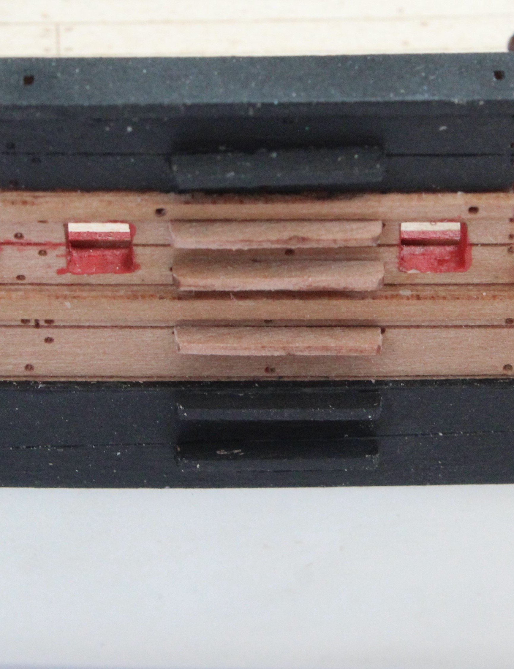
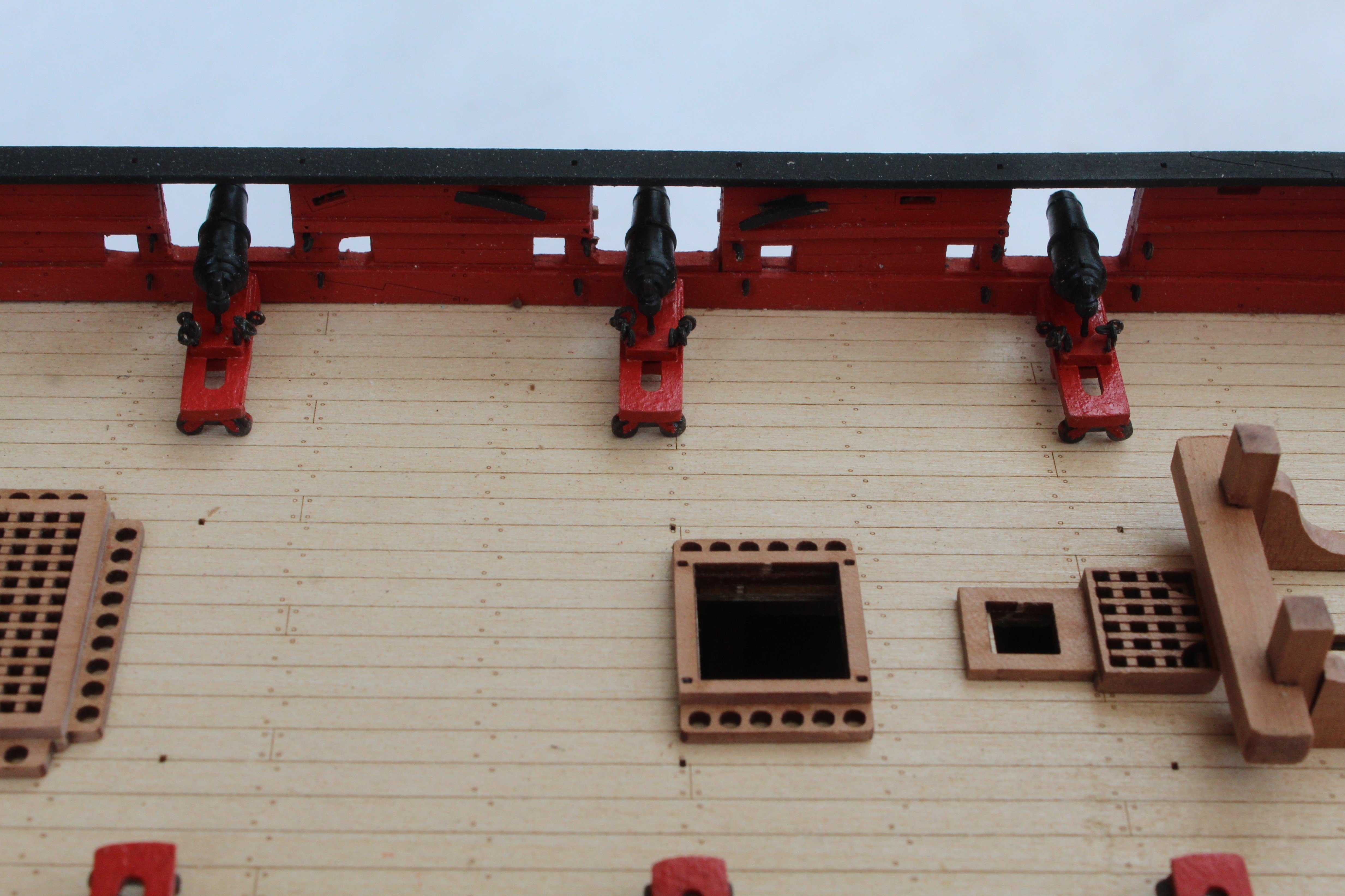
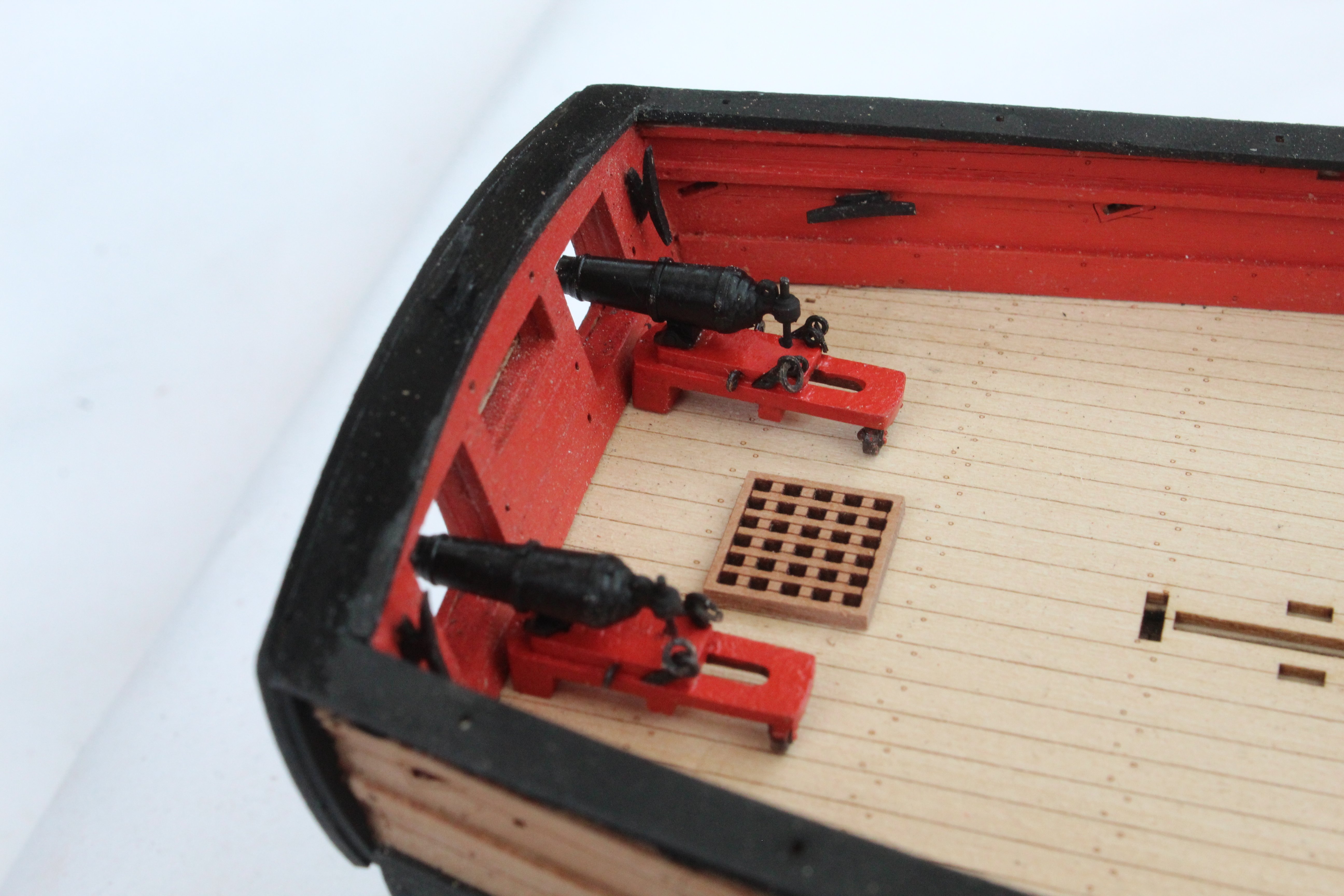
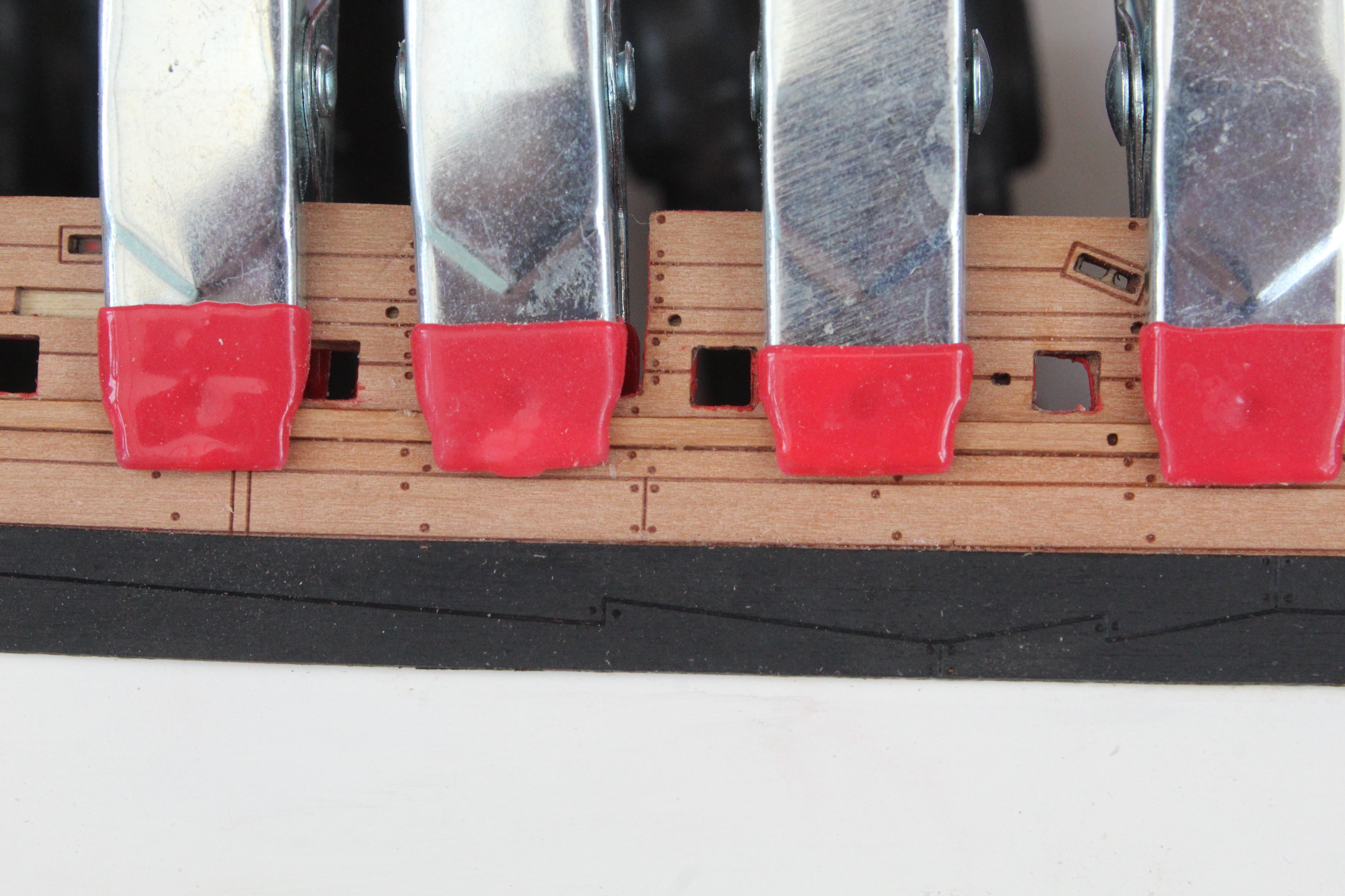
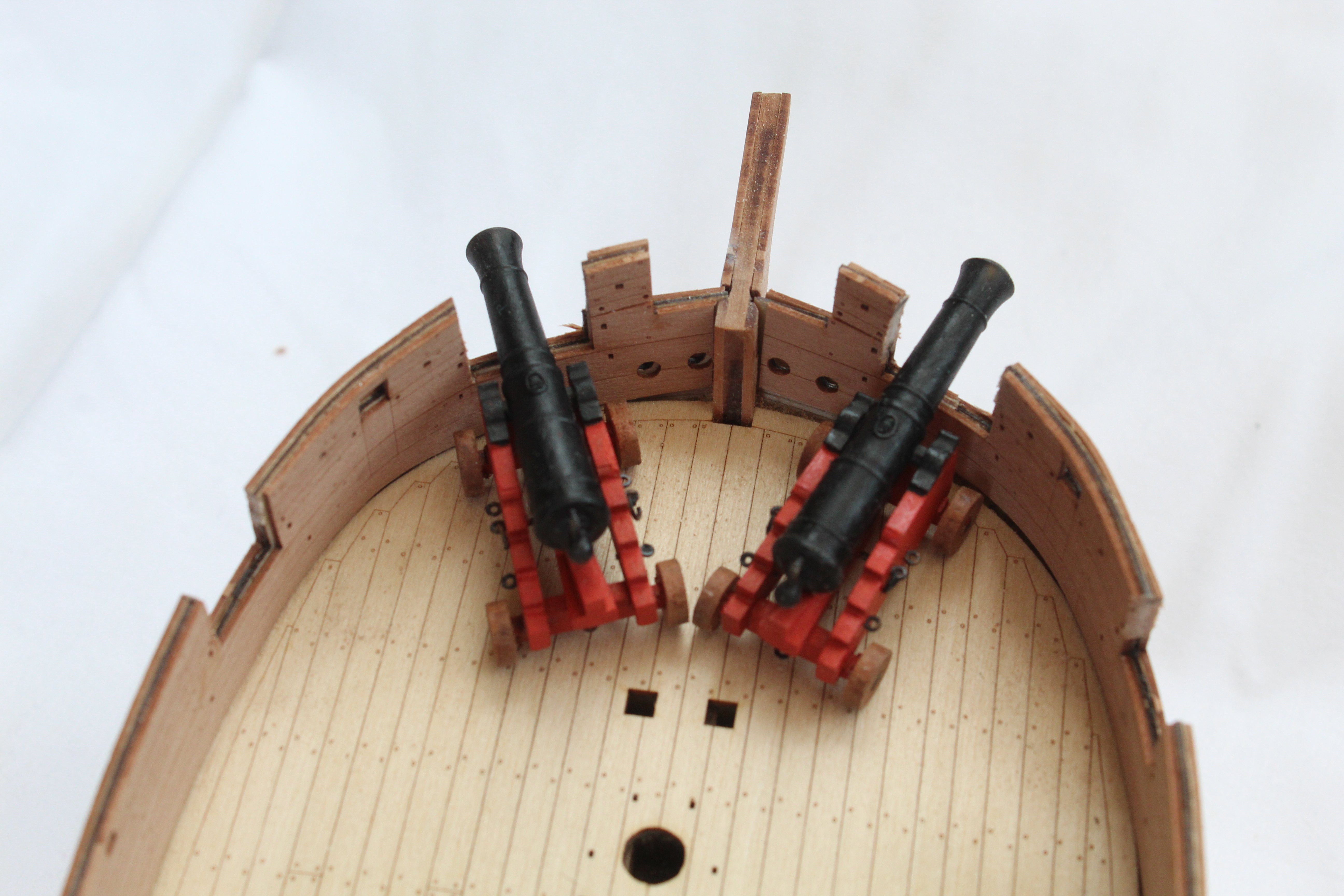
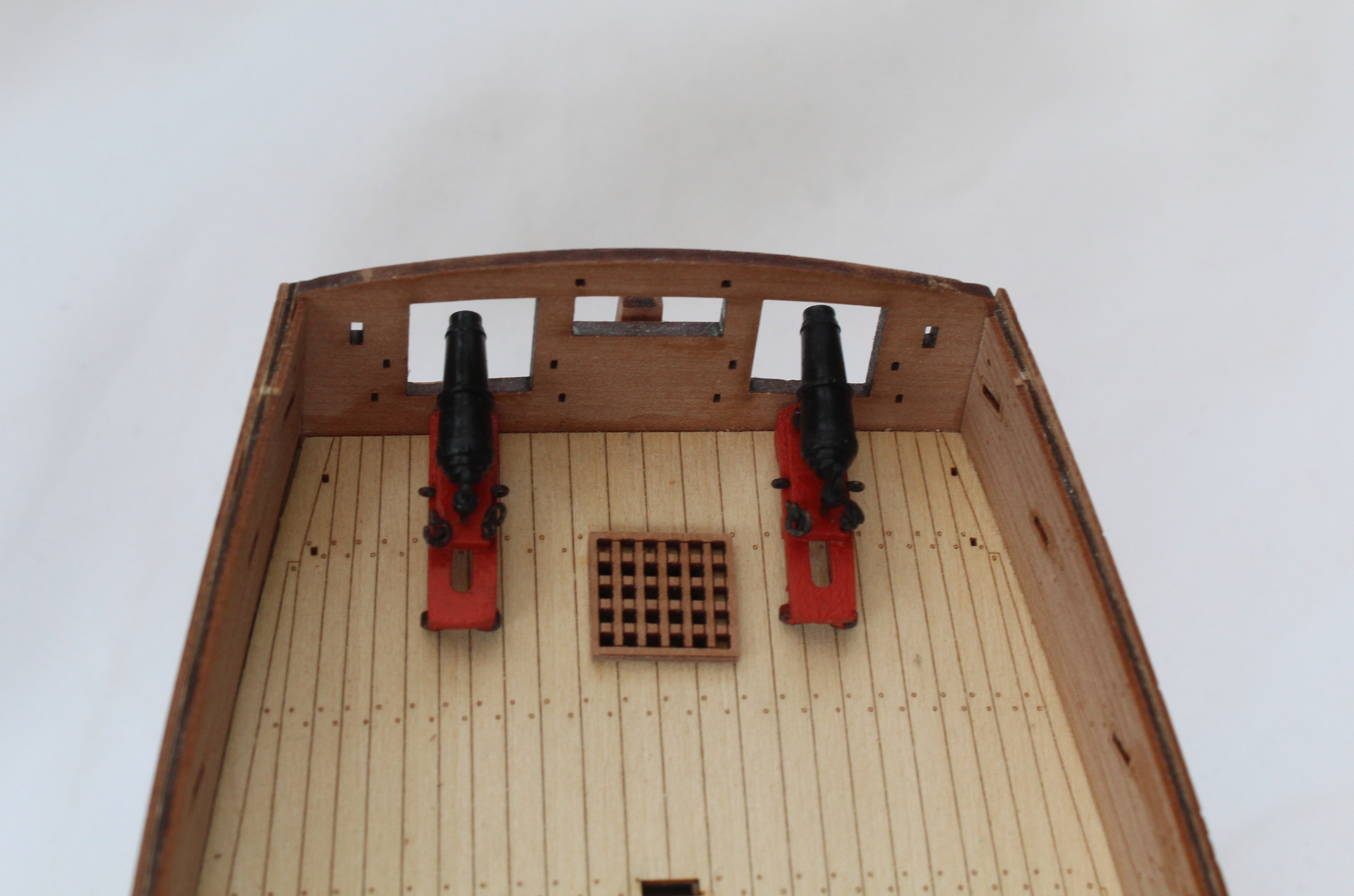
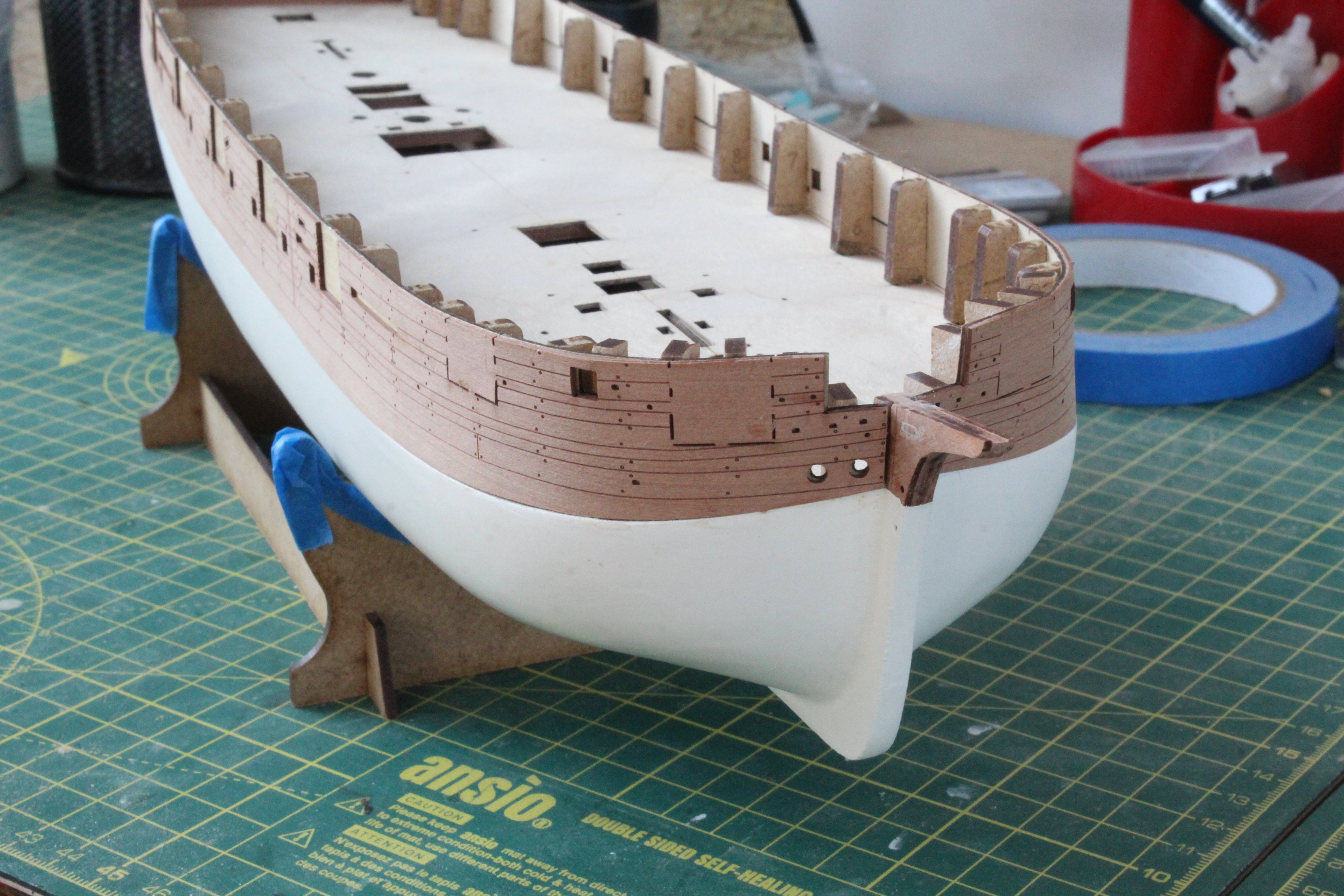
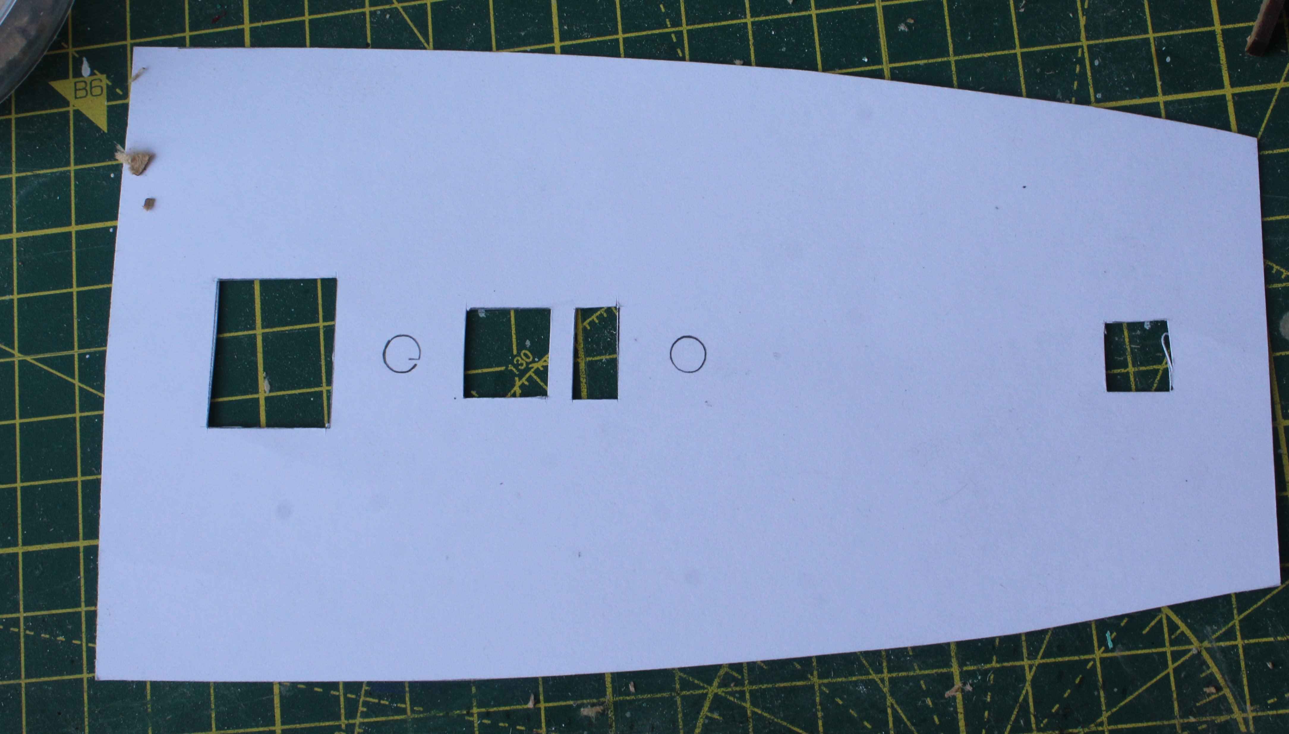
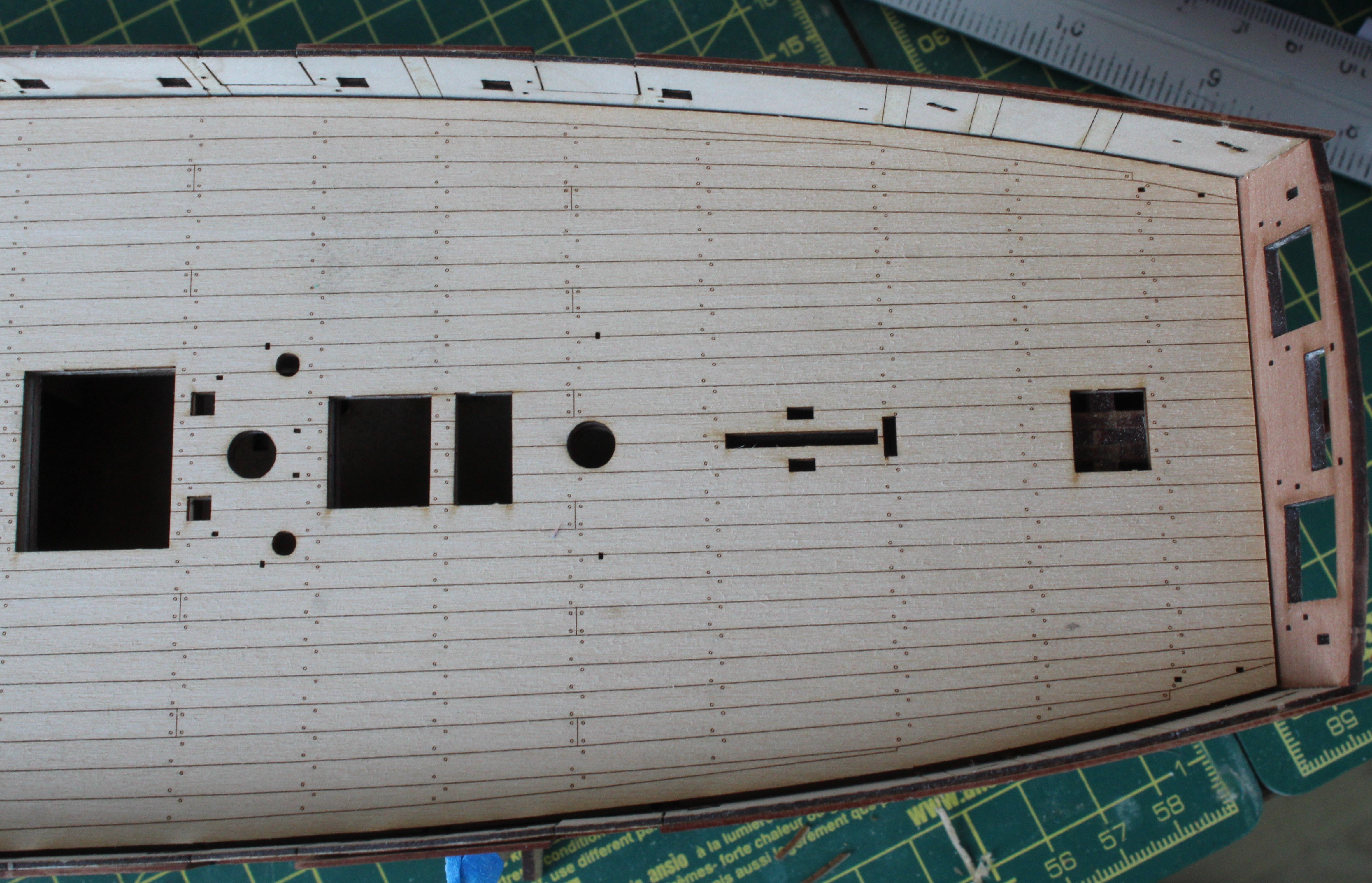
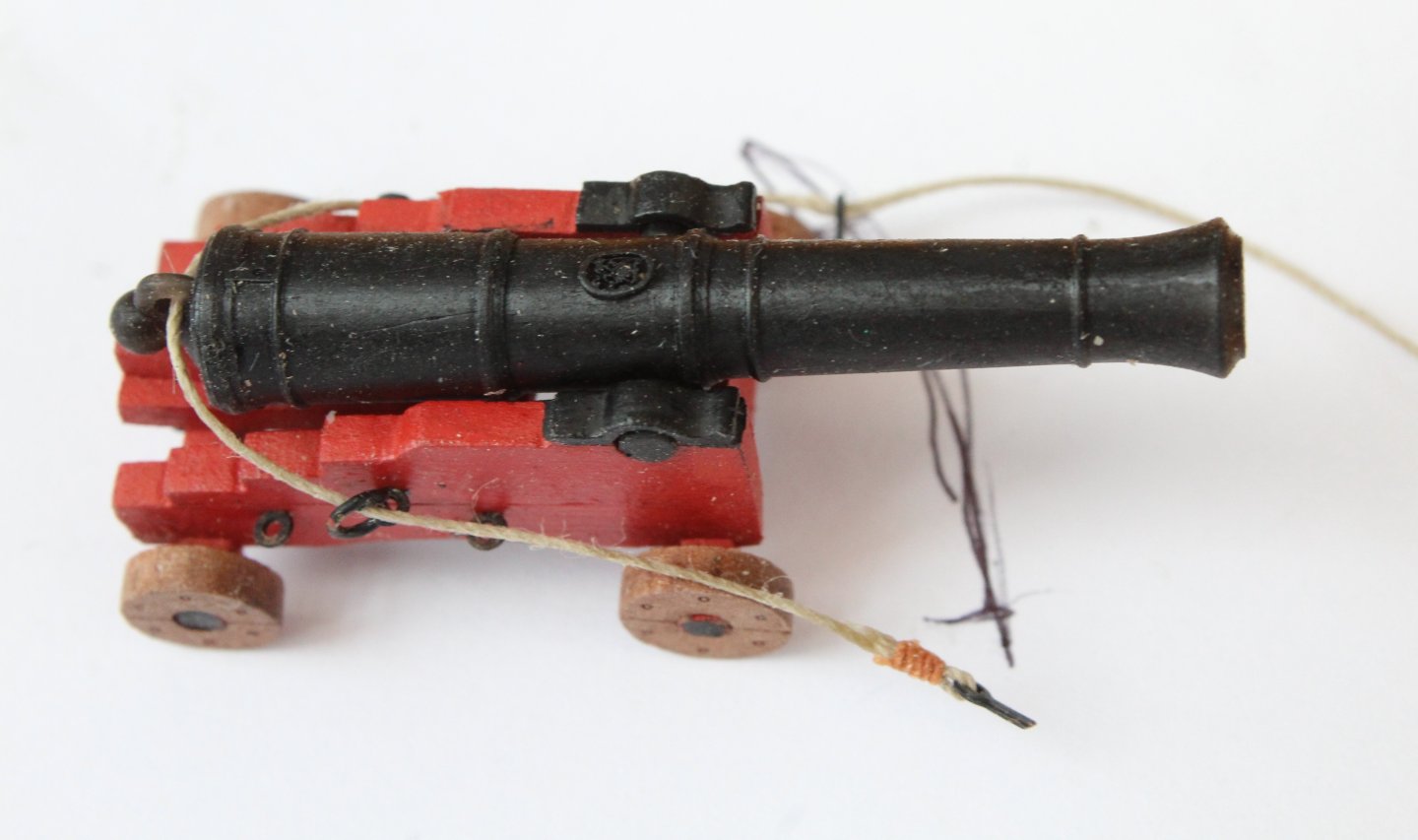
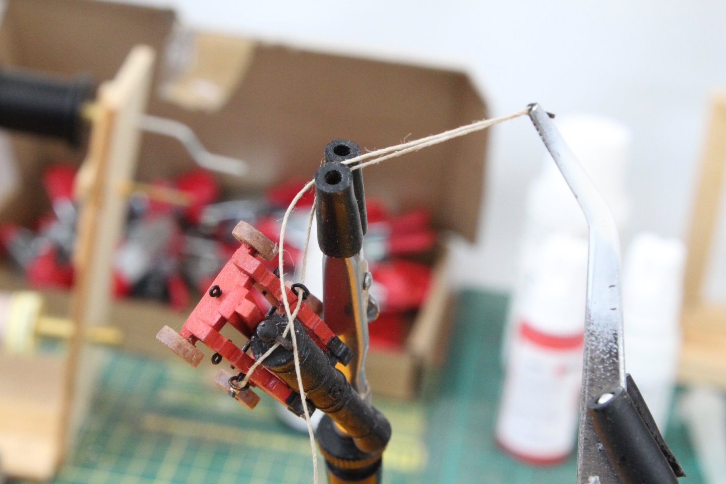
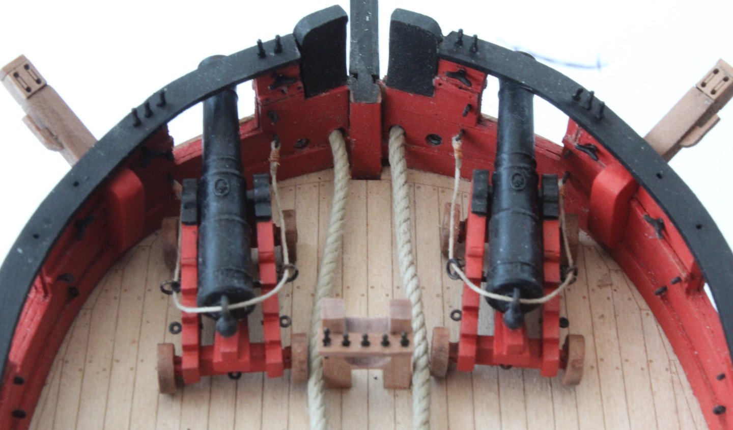
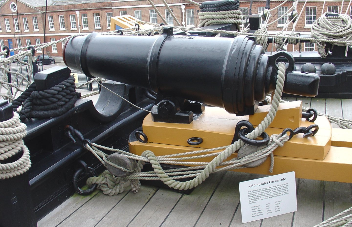
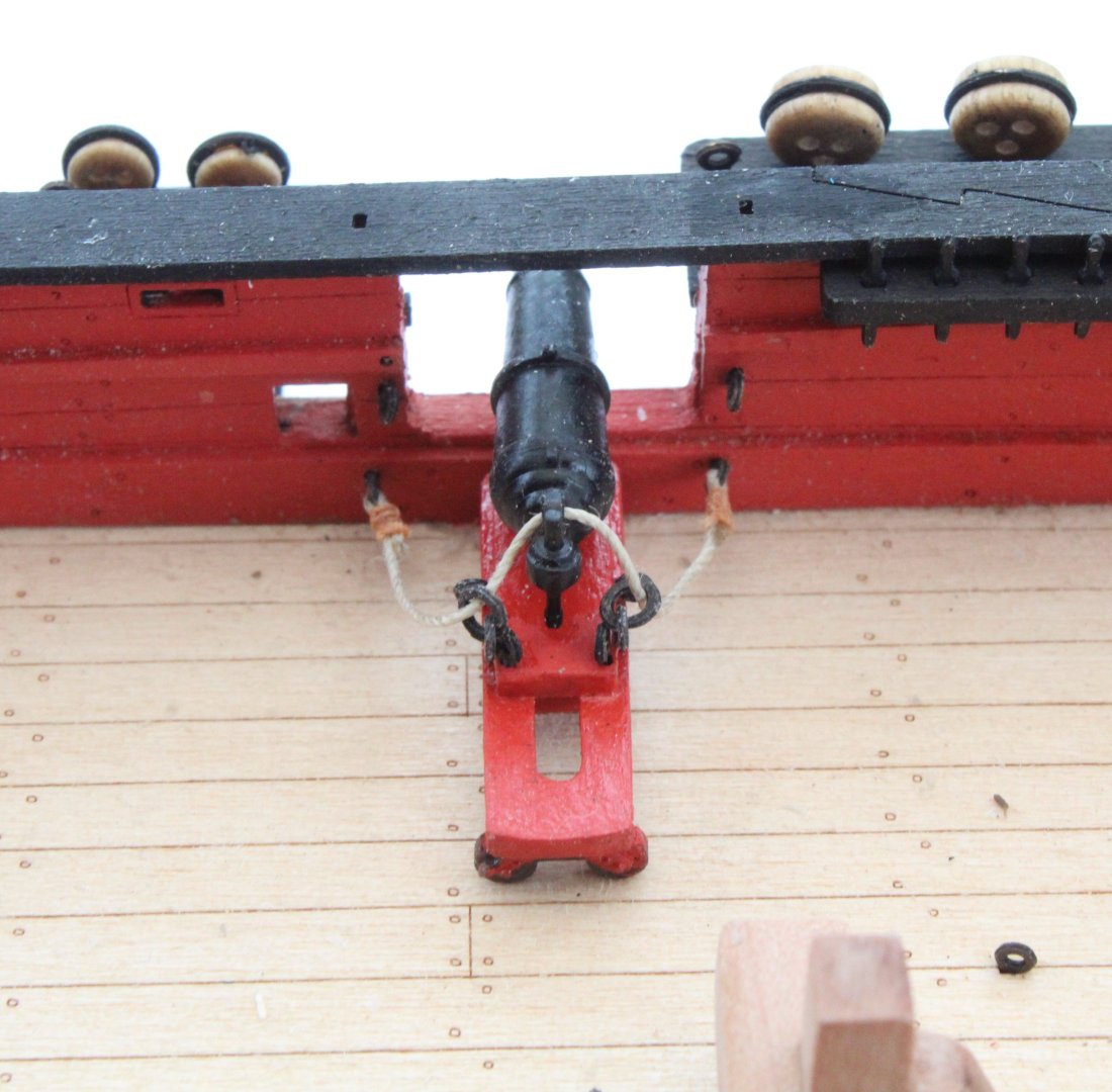
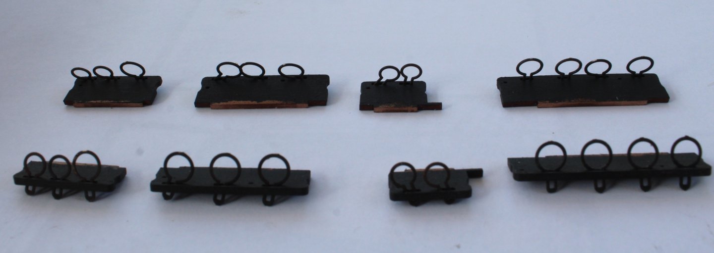
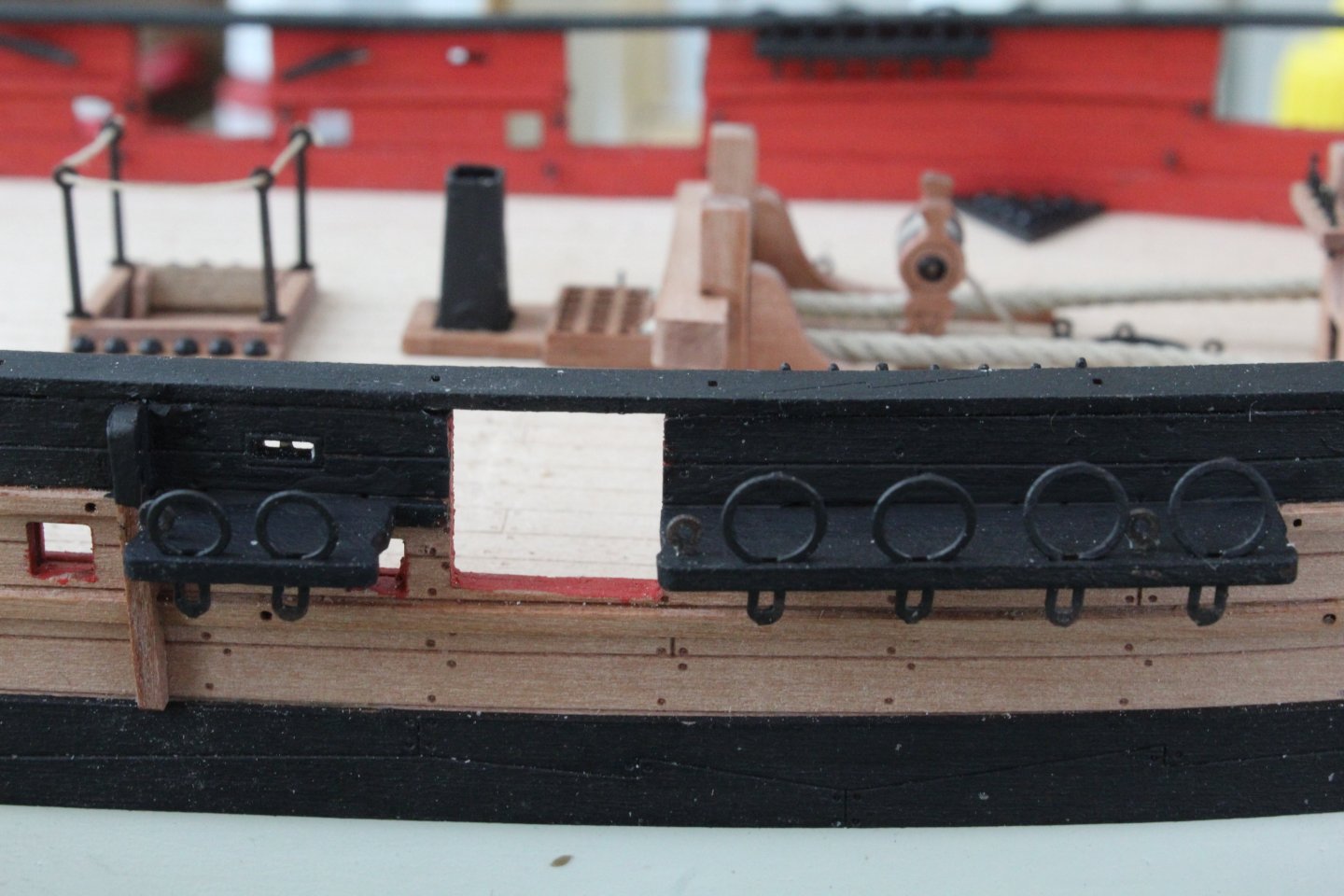
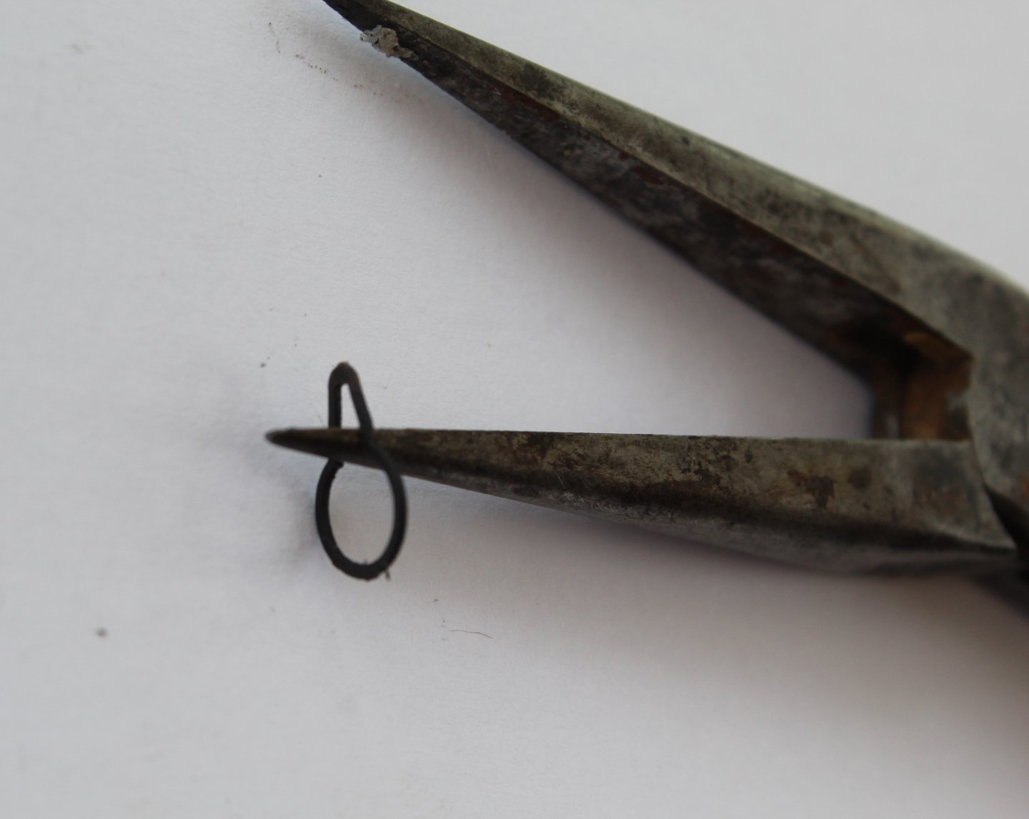
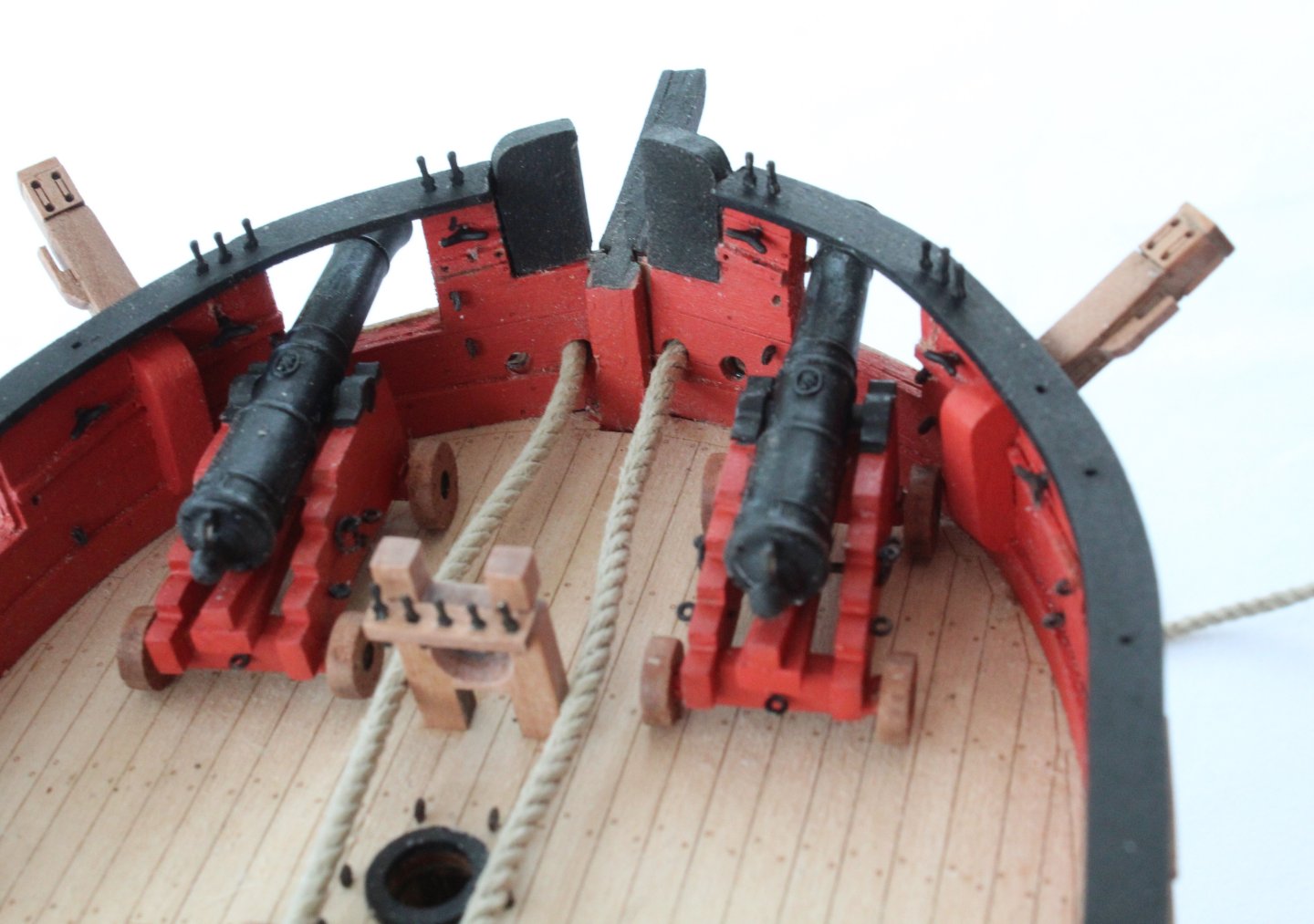
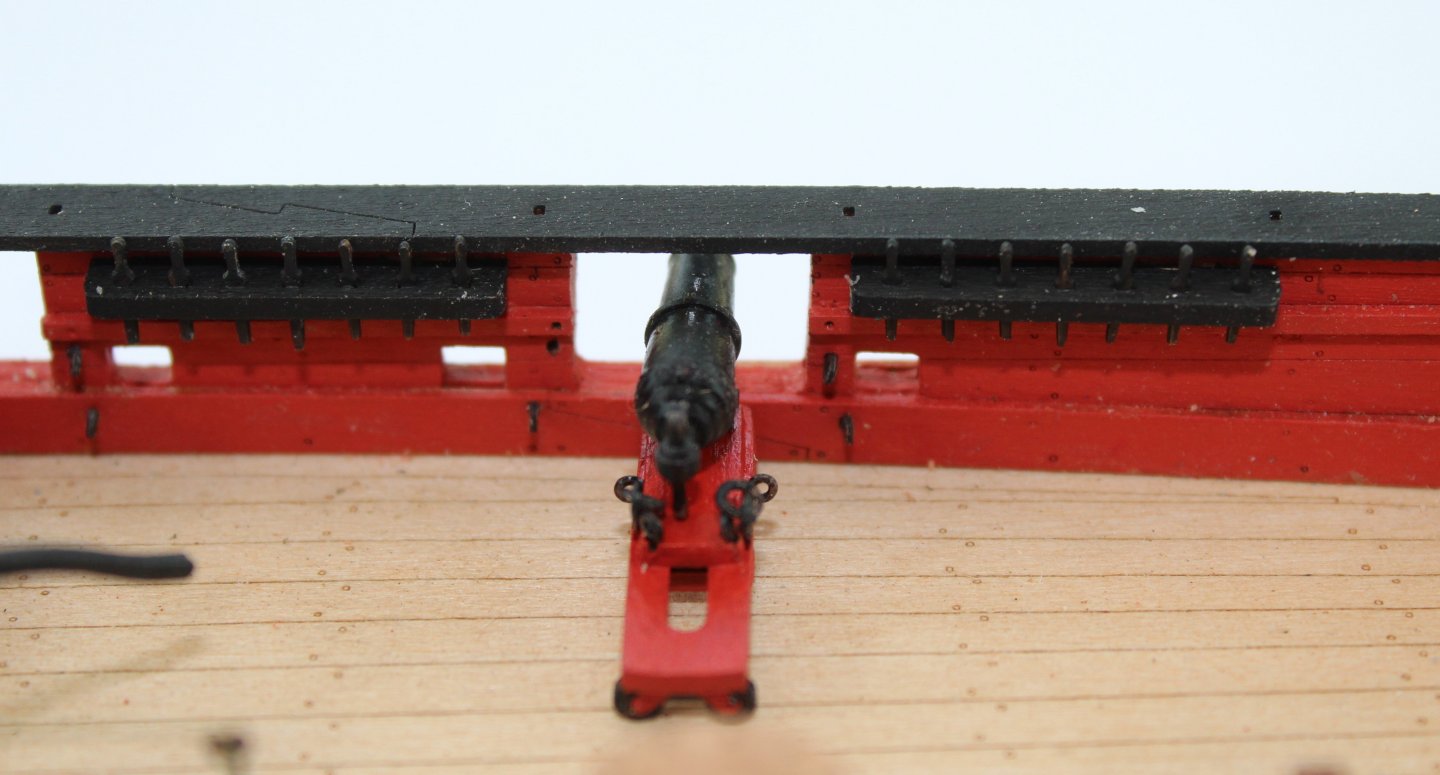
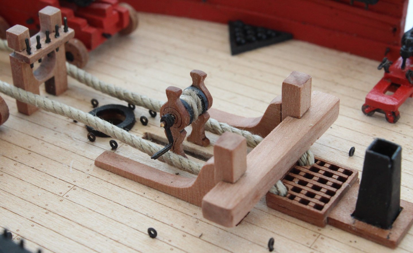
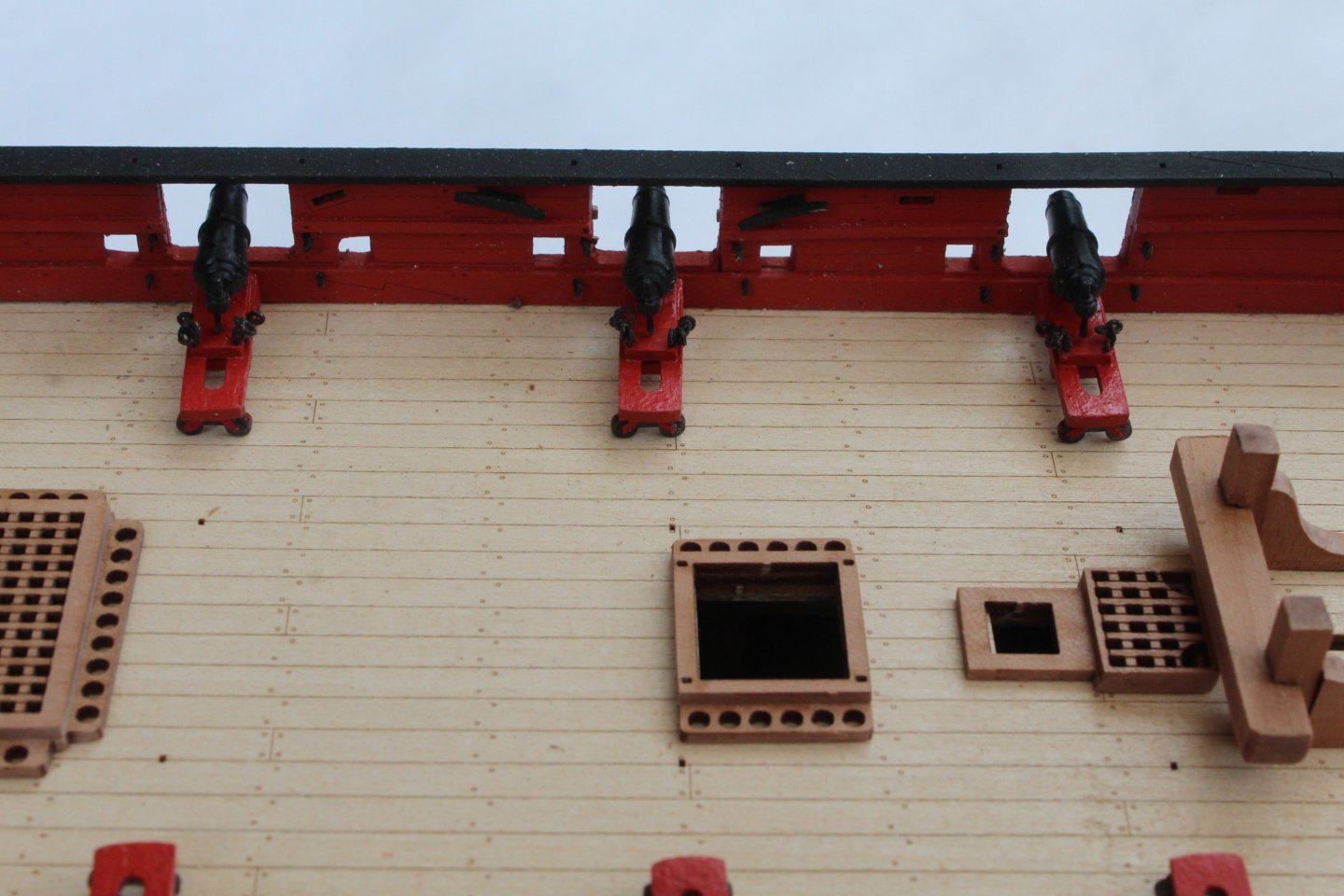
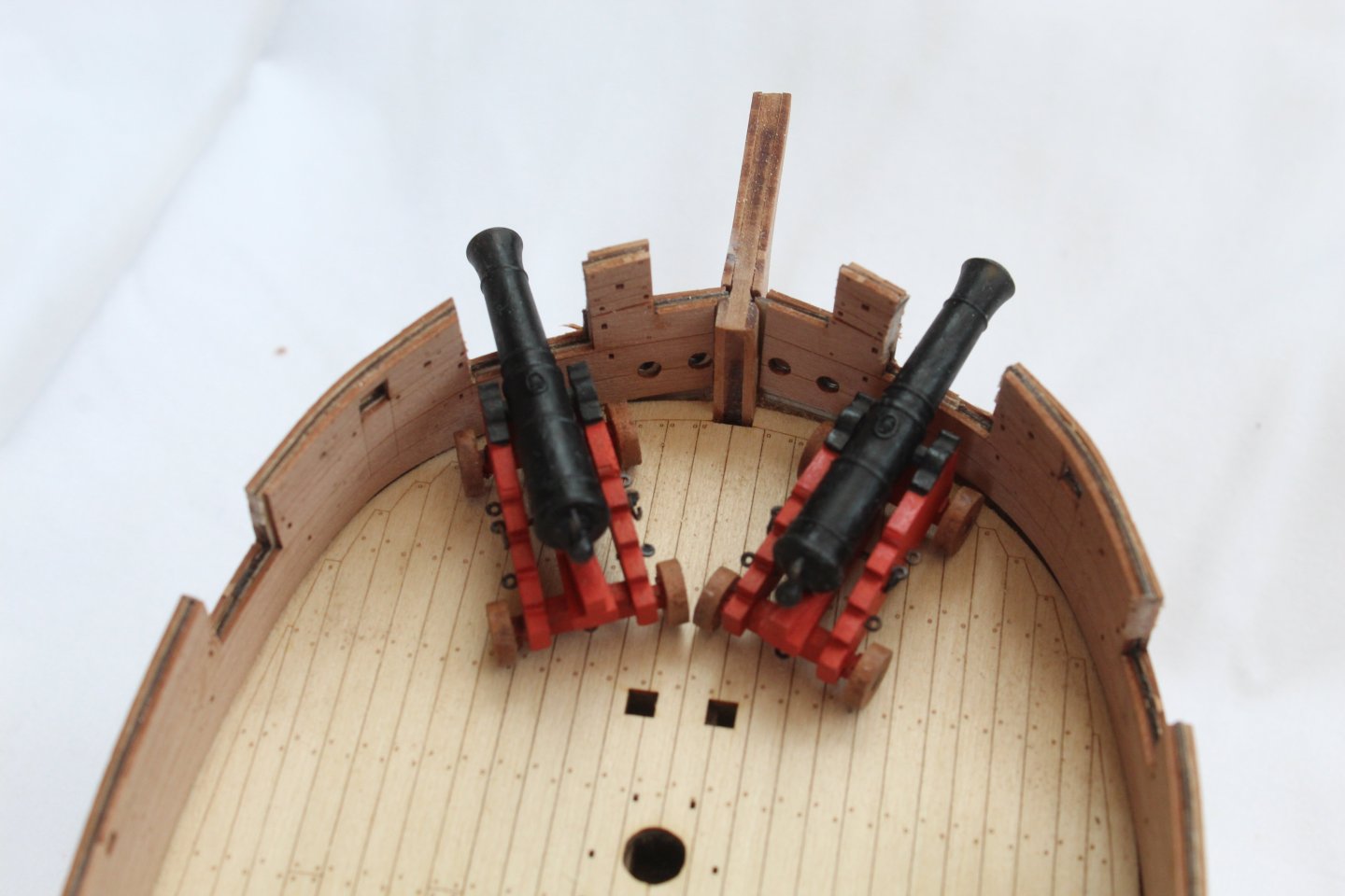
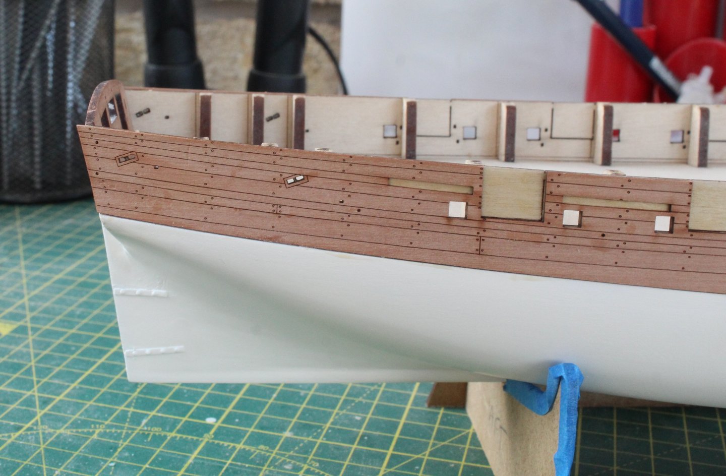
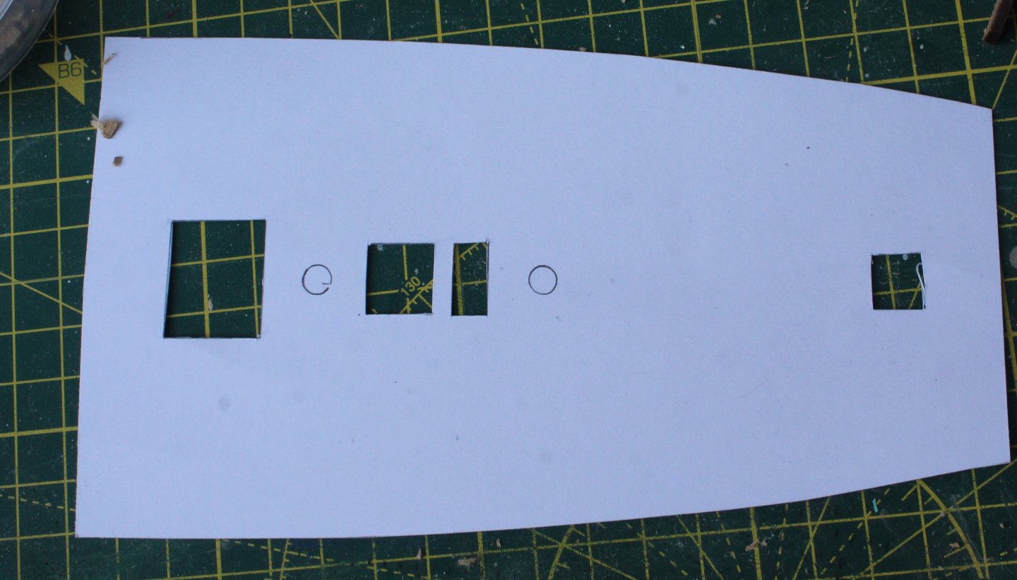
 Build Log Index Date: 01/09/2024 Time worked today: 1 hour. Total time spent on build: 65 hours. Cannon and Carronades Breach Rope Part 1 I was unsure if I should add the breach ropes for the cannons and carronades as I thought it might be difficult to seize the breach rope to the eyebolts in situ. I did have an idea of a method which would made the process much easier to implement and as it seems to work I thought I would document the method in this post. I started with a length of thread which was stiffened by running it through a block of beeswax and then melting the wax with a hair dryer to help it flow evenly over the thread. An eyebolt was then seized to one end of the thread using Guttermann thread colour 612-1 (brass) for the seizing. This is a nice constrast and is similar to some of the seizing noted when visiting the HMS Trincomalee. The quad hands makes this an an easy. I used 5 simple cross over knots top and bottom for the seizing. The thread was then added to the first cannon. After drawing the shape of the bow on a piece of paper the required position of the other eyebolt on the thread could be determined, noting the approx. positions of the eyebolts were also marked on the drawing. The second eyebolt was then seized to the thread, again using the quad hands. The next photo shows the first cannon with breach rope added. The position of the eyebolts were checked again with the template. The process works well and does not take too much time. I am reasonably happy with the end result. It was then a case of repeating the process for the other cannon. The eyebolts and cannons have not be glued in place in the photo below. I will need to straighten the two cannons as the right-hand would, in particular, is not totally straight as can be noted in the photo below. I am using the following picture as my point of reference for the carronade breach rope rigging. It might be correct for the Adder carronades. Using the same process the seizing the two eyebolts have been added to the first carronade and they are now ready be checked with the template. The first carronade, complete with the breach rope, in position is shown in the final photo of this post. The method works well and takes around 10 minutes per carronade to implement so there is about 2 hours work left to complete the remaining carronade’s.


-
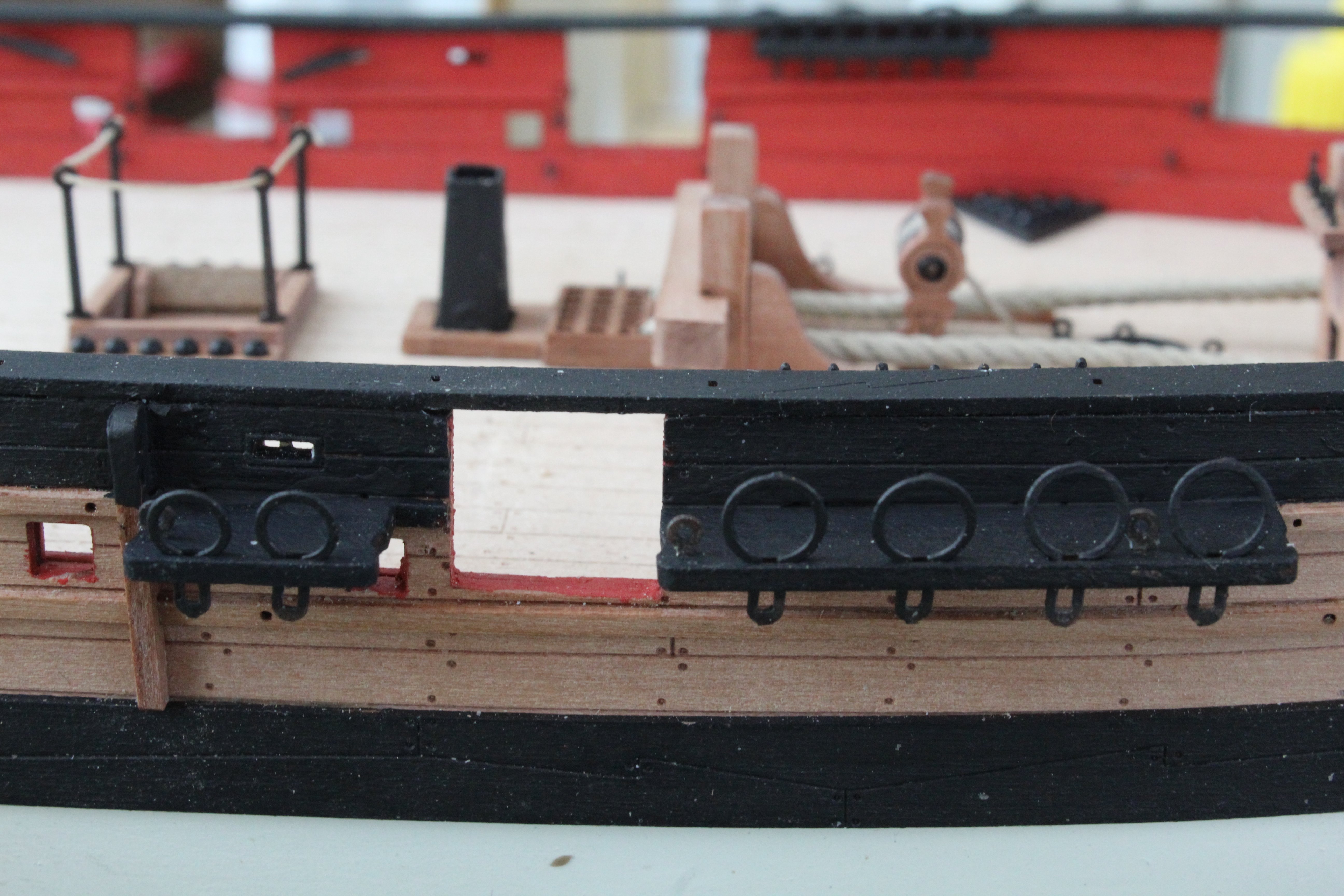
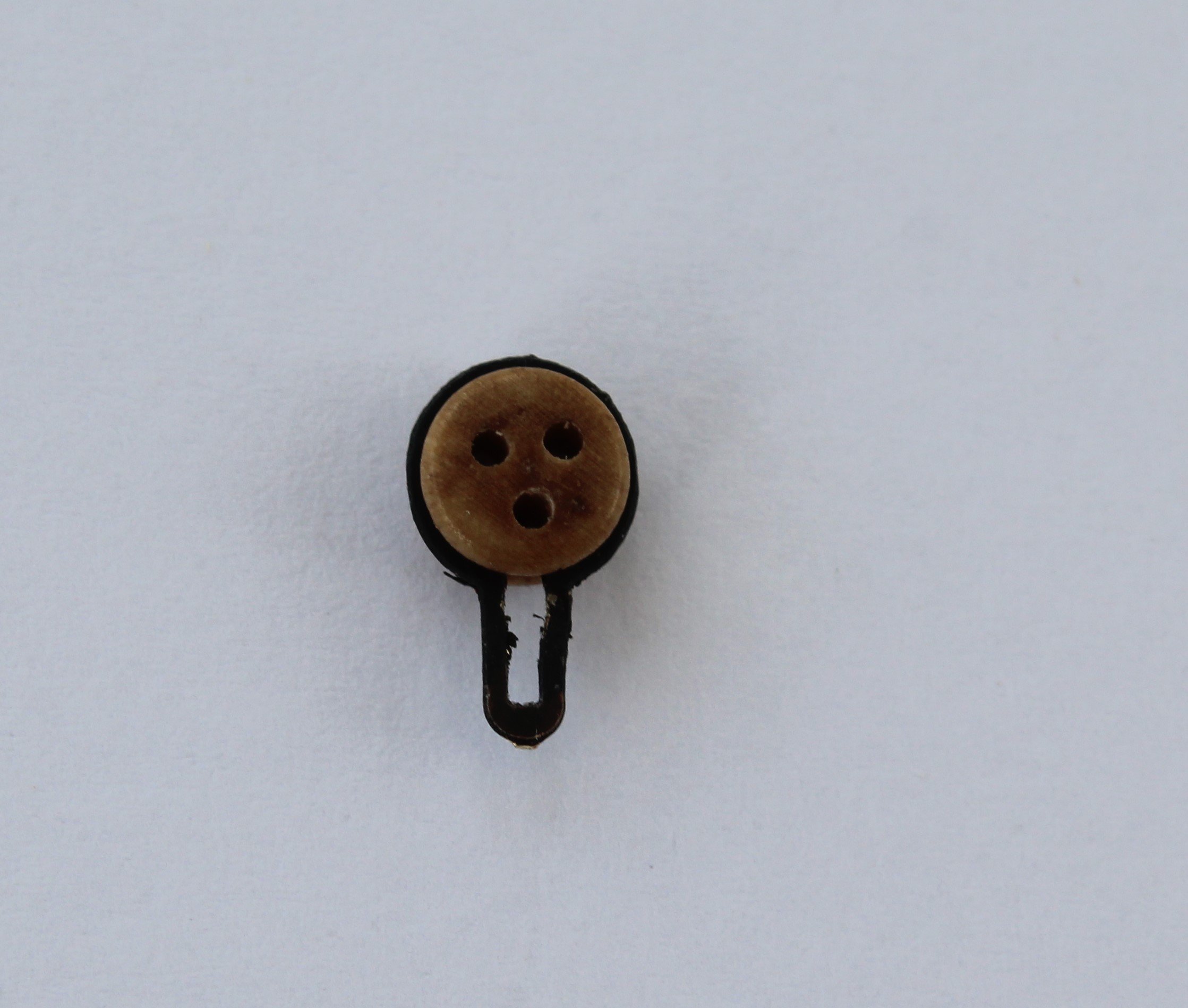
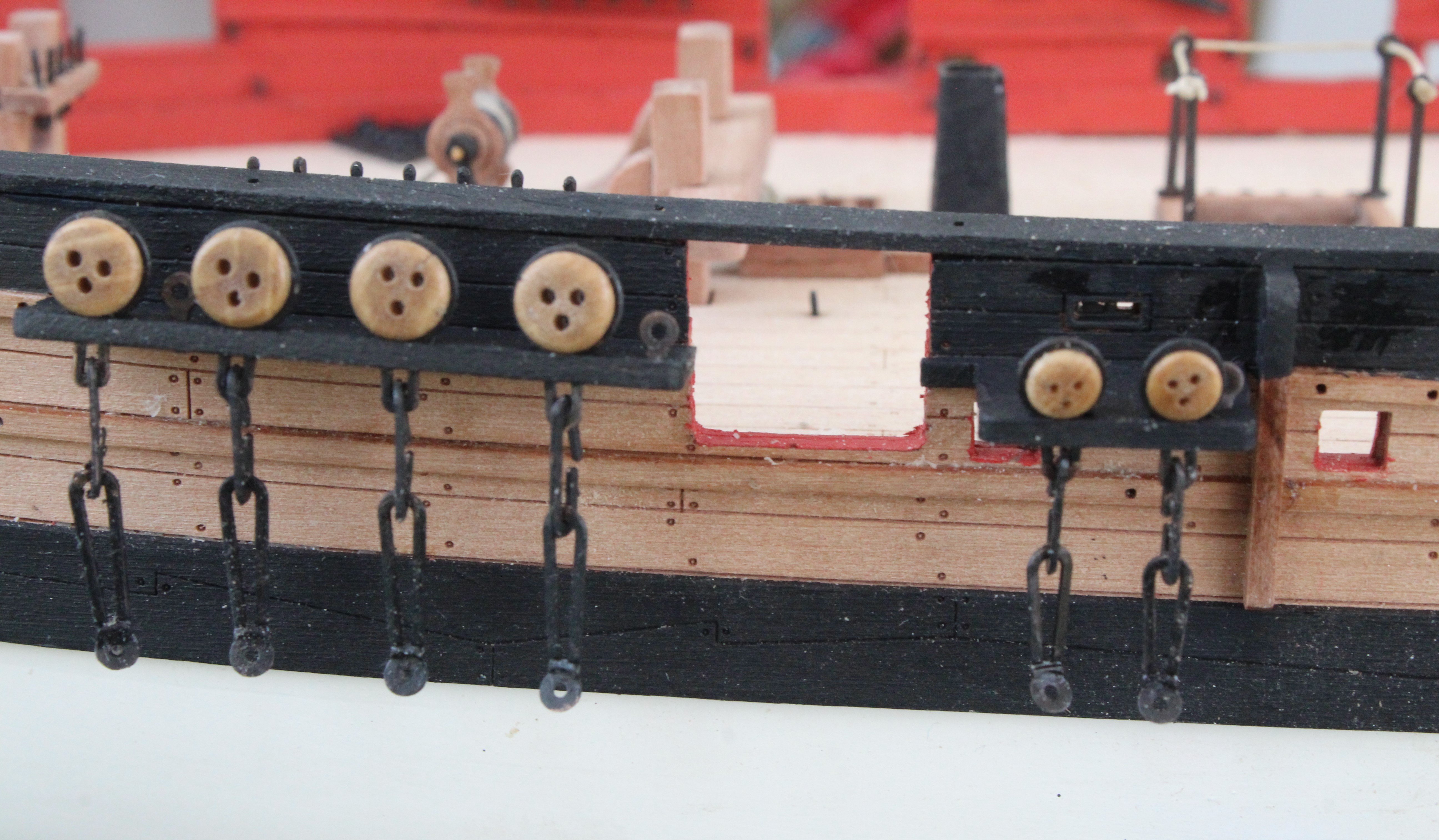
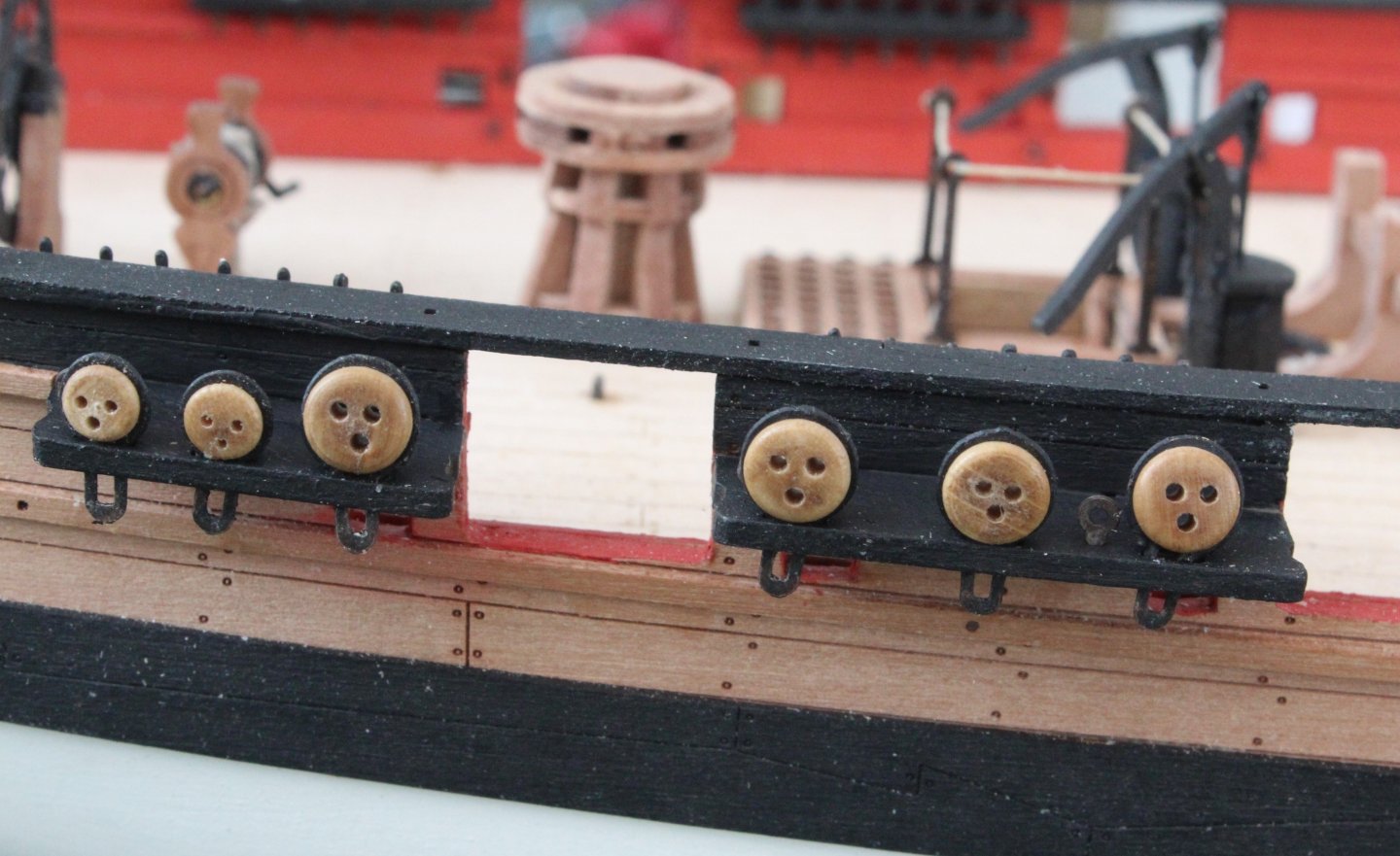
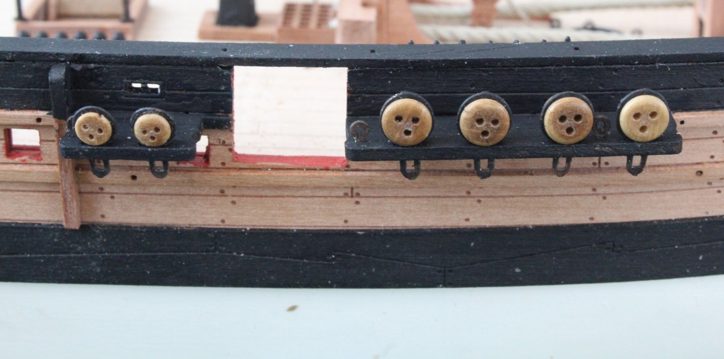
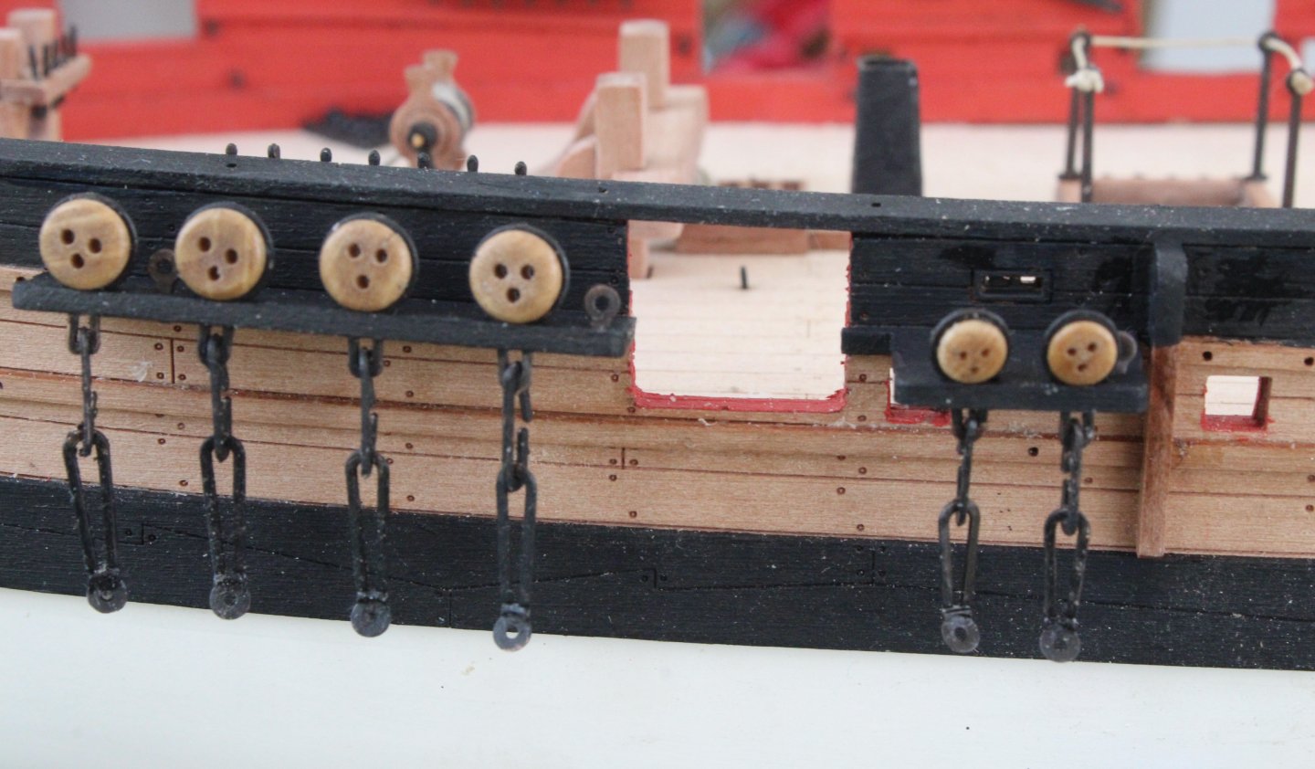
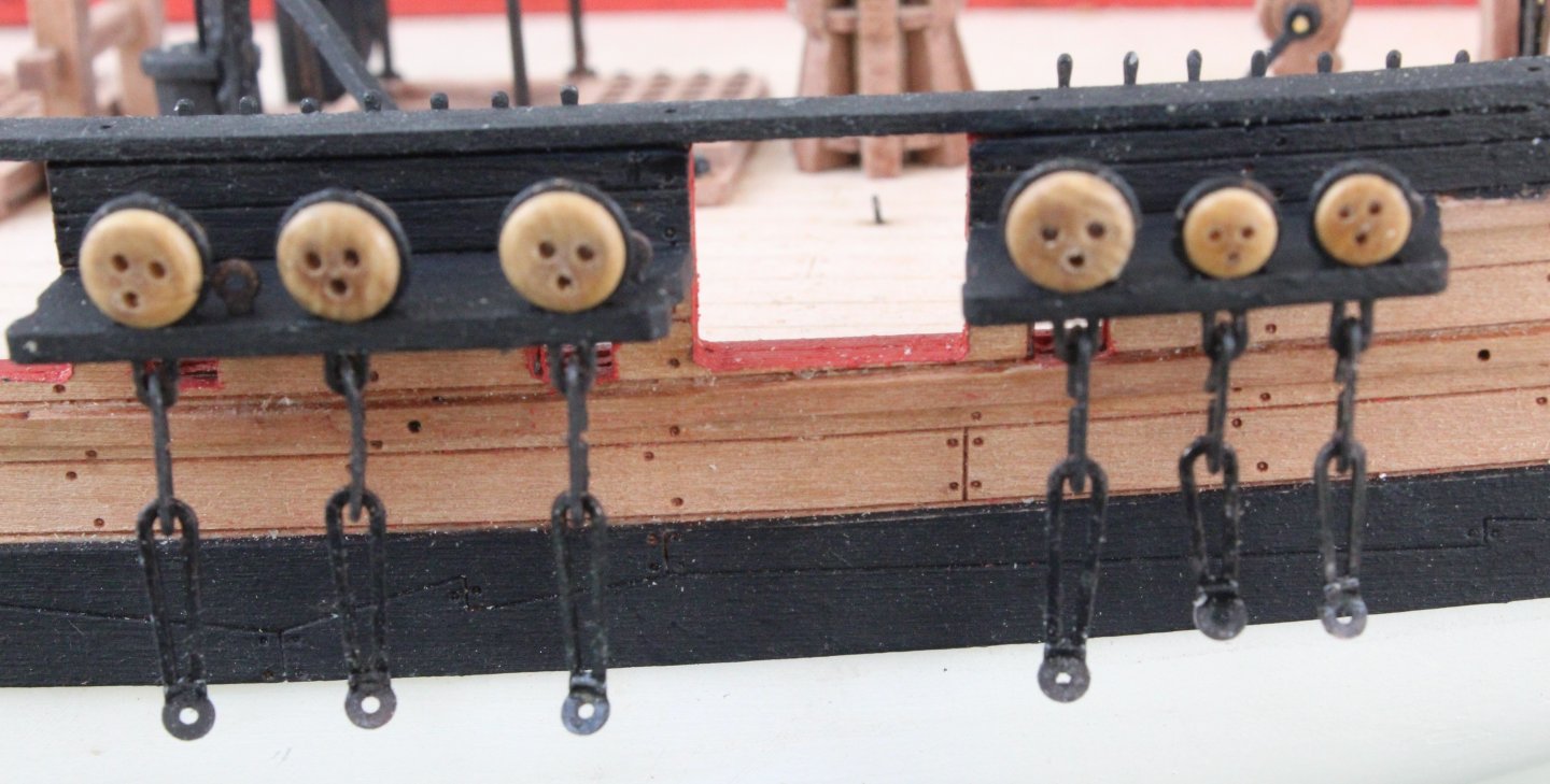
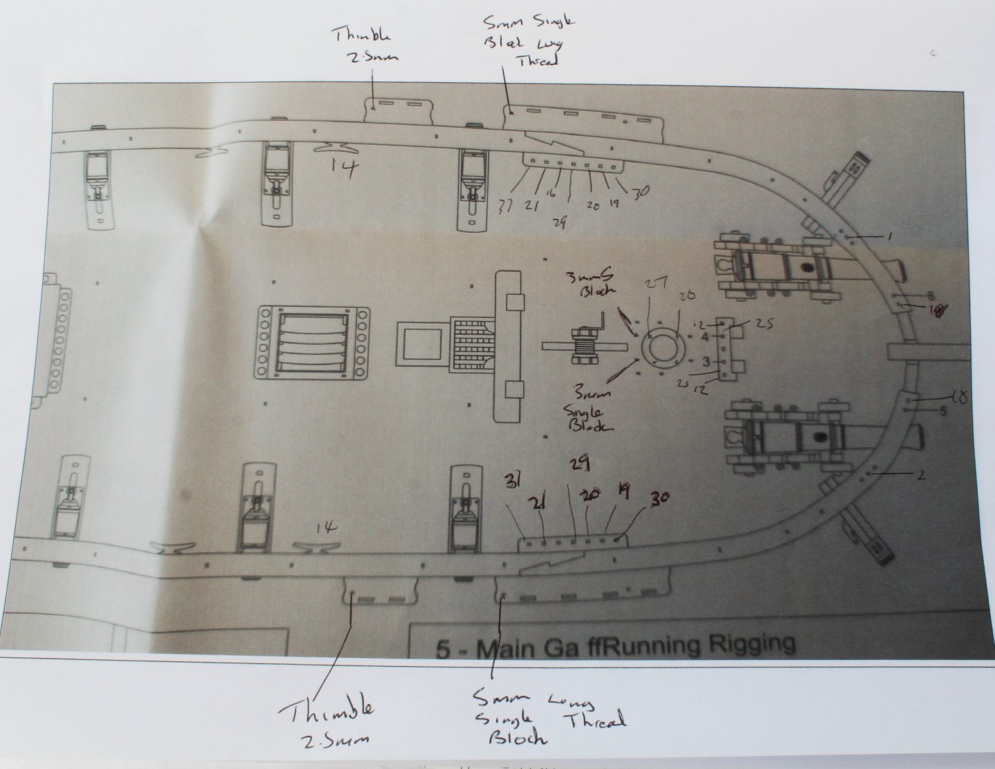
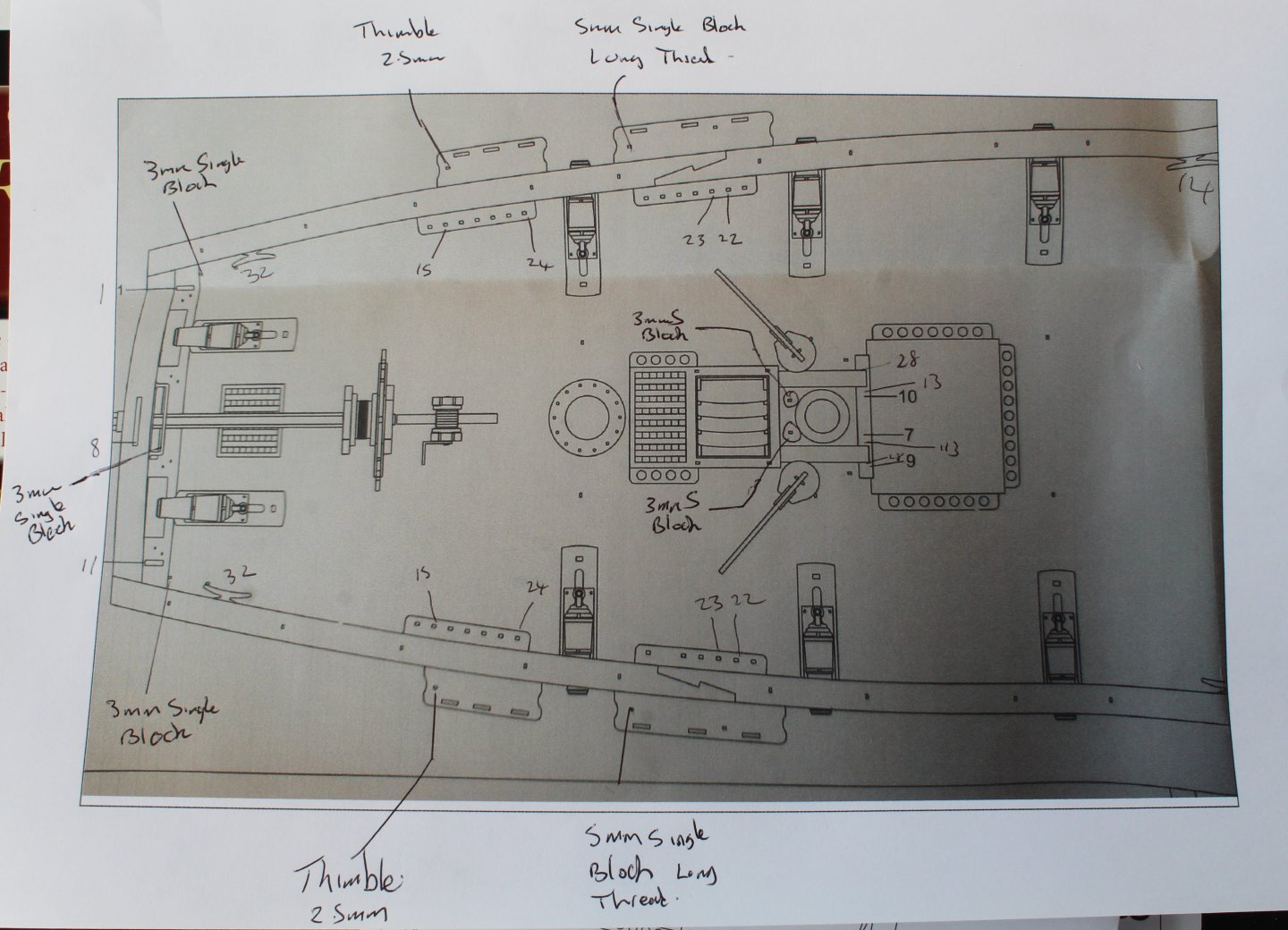
Build Log Index Date: 31/08/2024 Time worked today: 4 hours. Total time spent on build: 64 hours. Channels The various channels, after a coat of varnish was applied, were painted with two coats of black paint. The deadeye strops and chainplates were chemically blackened. The deadeye strops were then test fitted in the channels The channels were then, using wood glue, affixed to the hull. I have placed the eyebolts in the channels, but I have not glued them in as some will require thimbles and/or eyebolts seizing to them. It will be easier to do this using my quad hands before they are added to the channels. Next it was time to fit the deadeyes to the strops. I used my pliers to gently open the gap, as shown below. After the deadeye was inserted in the strop and aligned I used the pliers to close up the gap. The strops, complete with deadeyes were then placed in the channels. The holes in many of the supplied 3.5mm deadeyes are not very even so I had to pick and choose the ones to use. I do have plenty of 3mm pear deadeyes, but they were a bit to small for the strops. Next the chainplates were added. I chemically blackened the pins but I have not use them to secure the chainplates to the hull as I am waiting until after I have added the masts so I can align the chainplates with the flow of their respective shroud lines In preparation for the rigging phase I have studied the rigging plans and charted the various belaying points as shown below. I have also indicated where blocks /thimbles are to be added to eyebolts as I find this easier to do before the eyebolts are glued in place.

-
Many thanks Andrew. It is a great model to build.
-
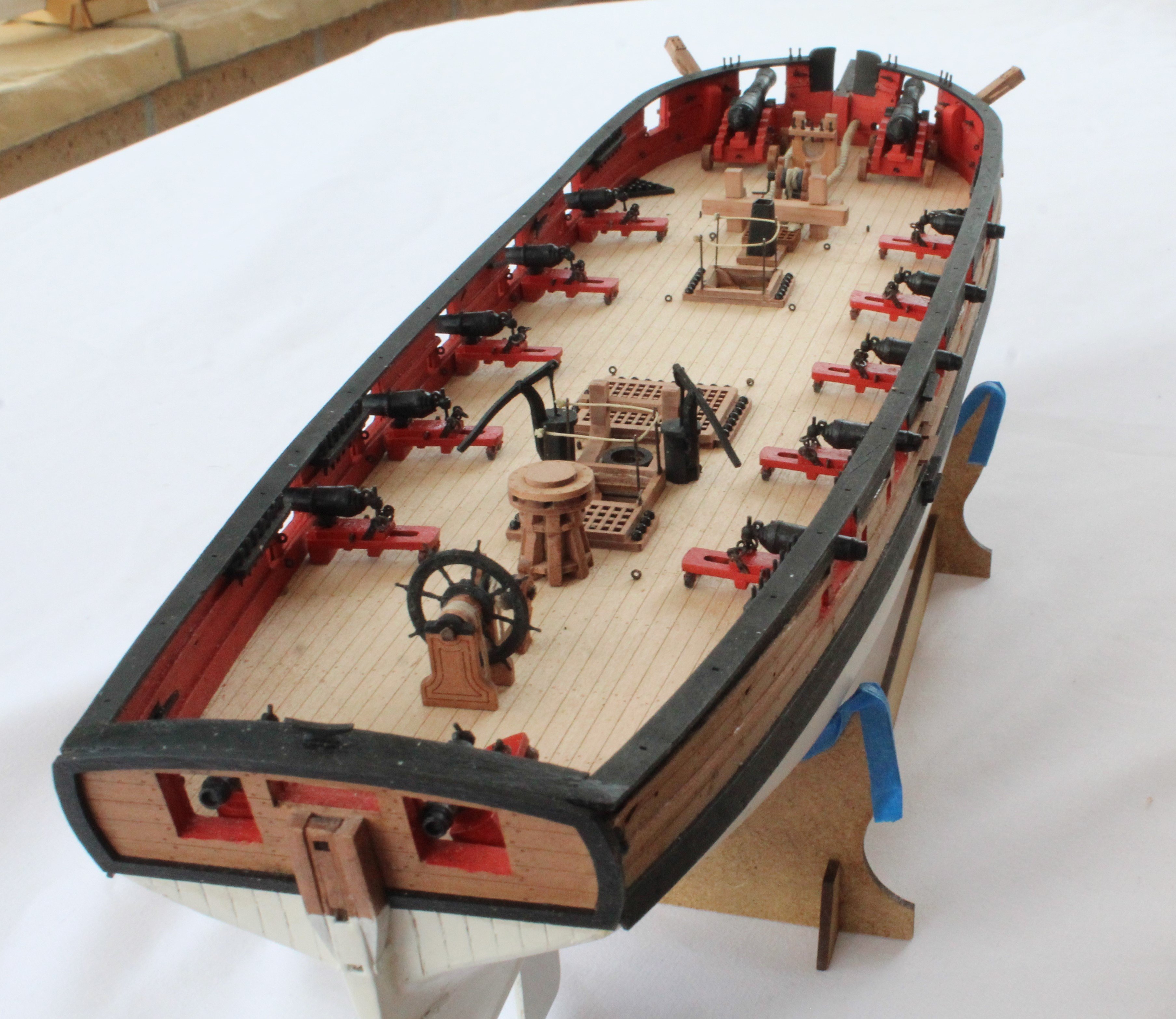
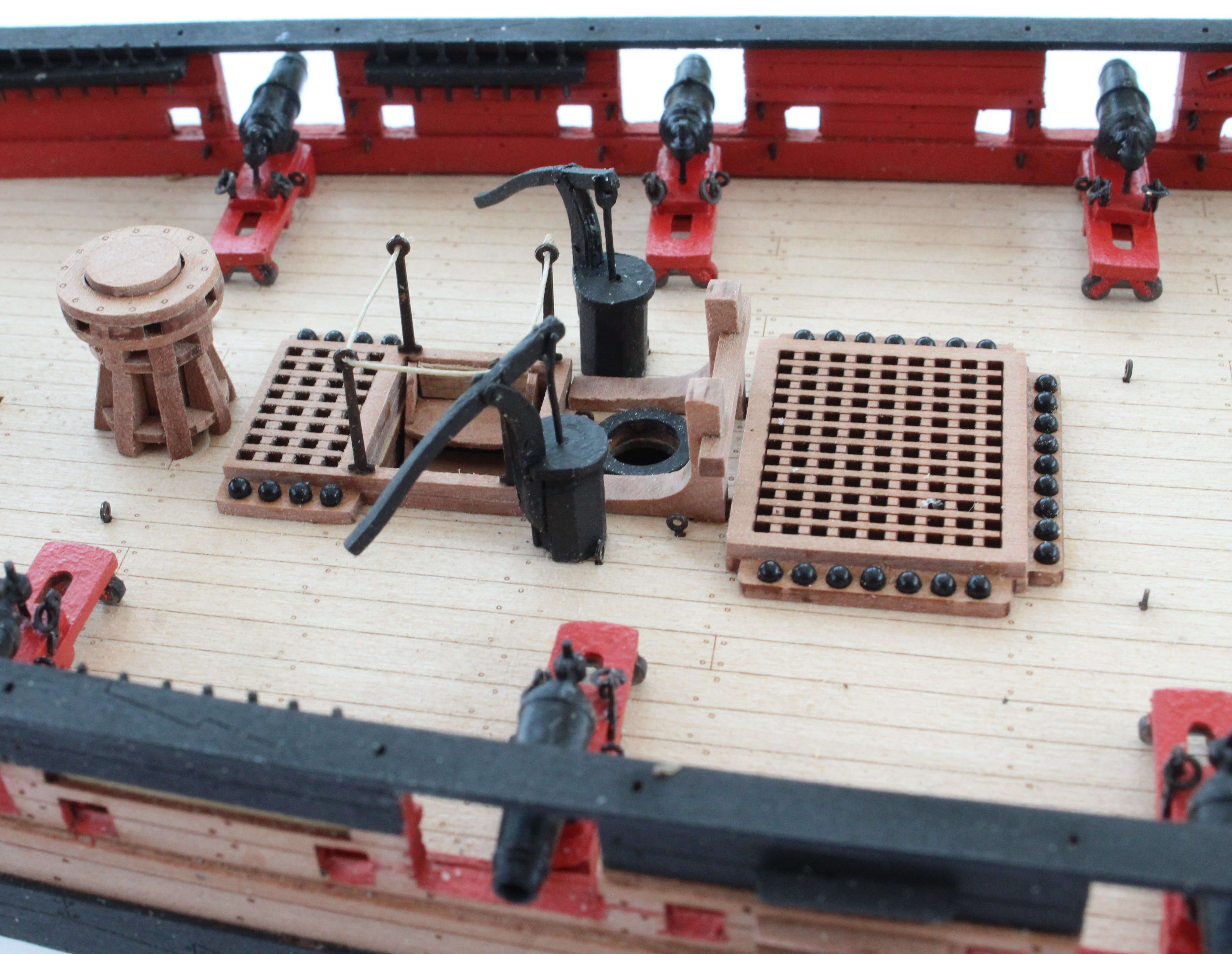
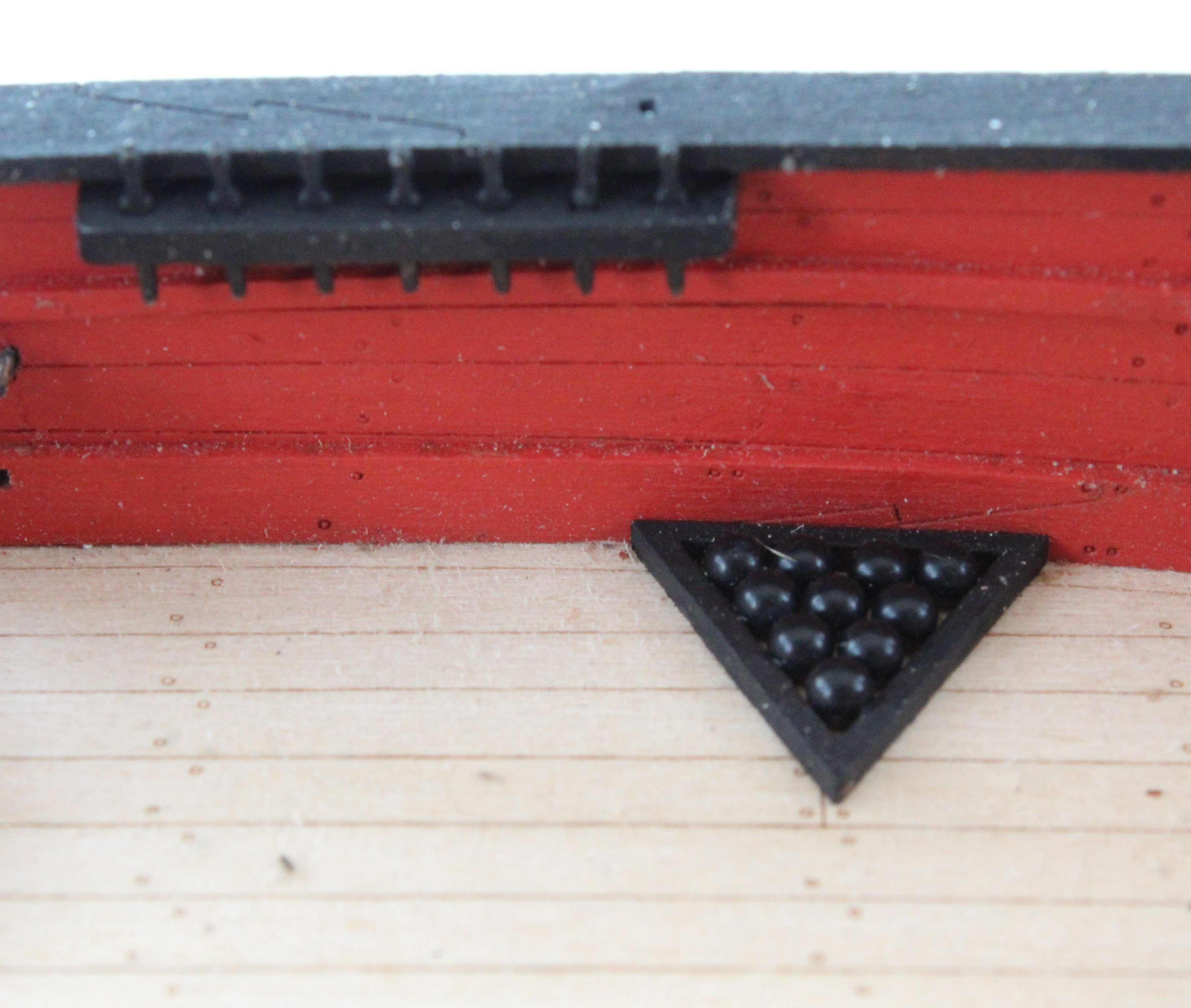
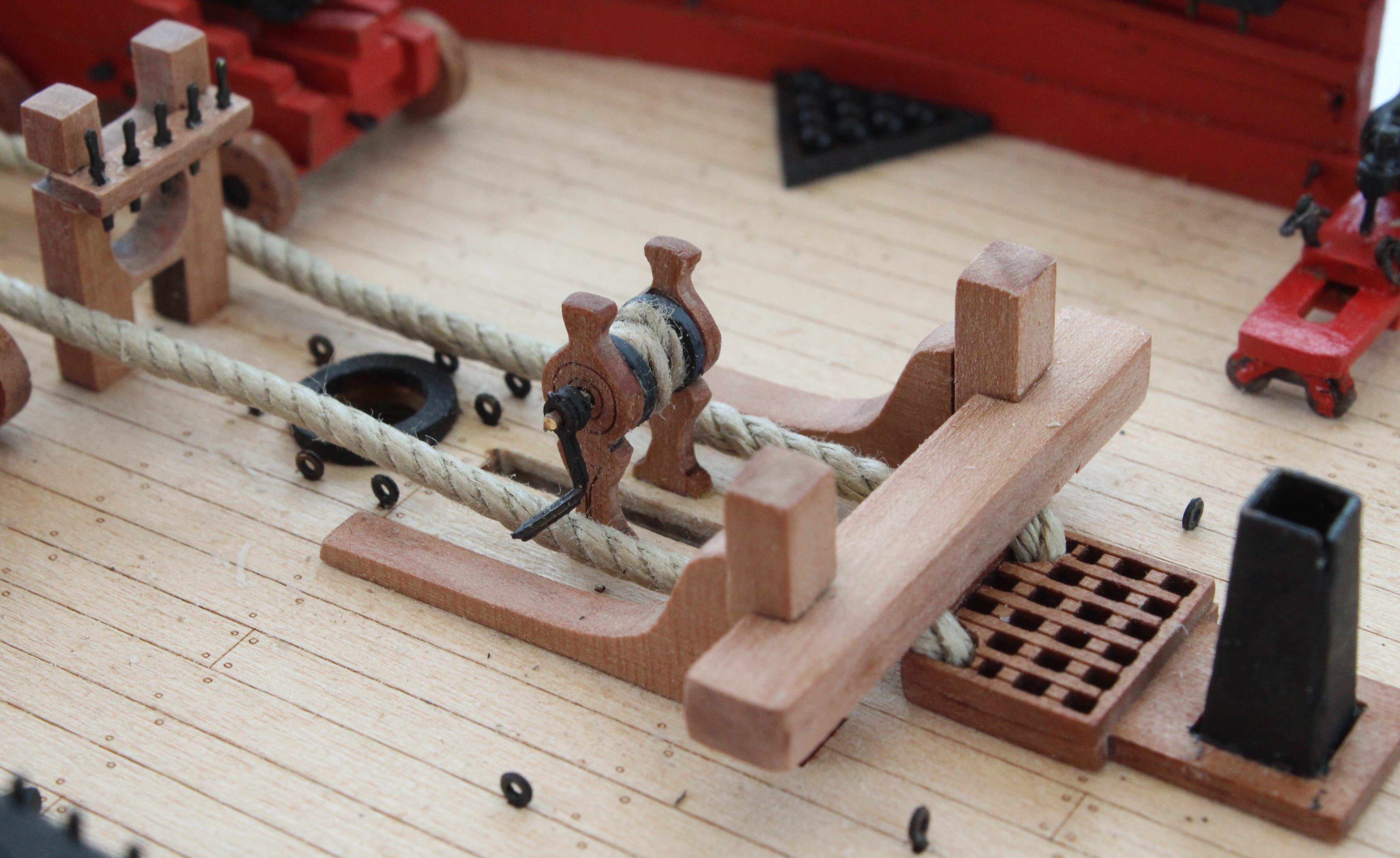
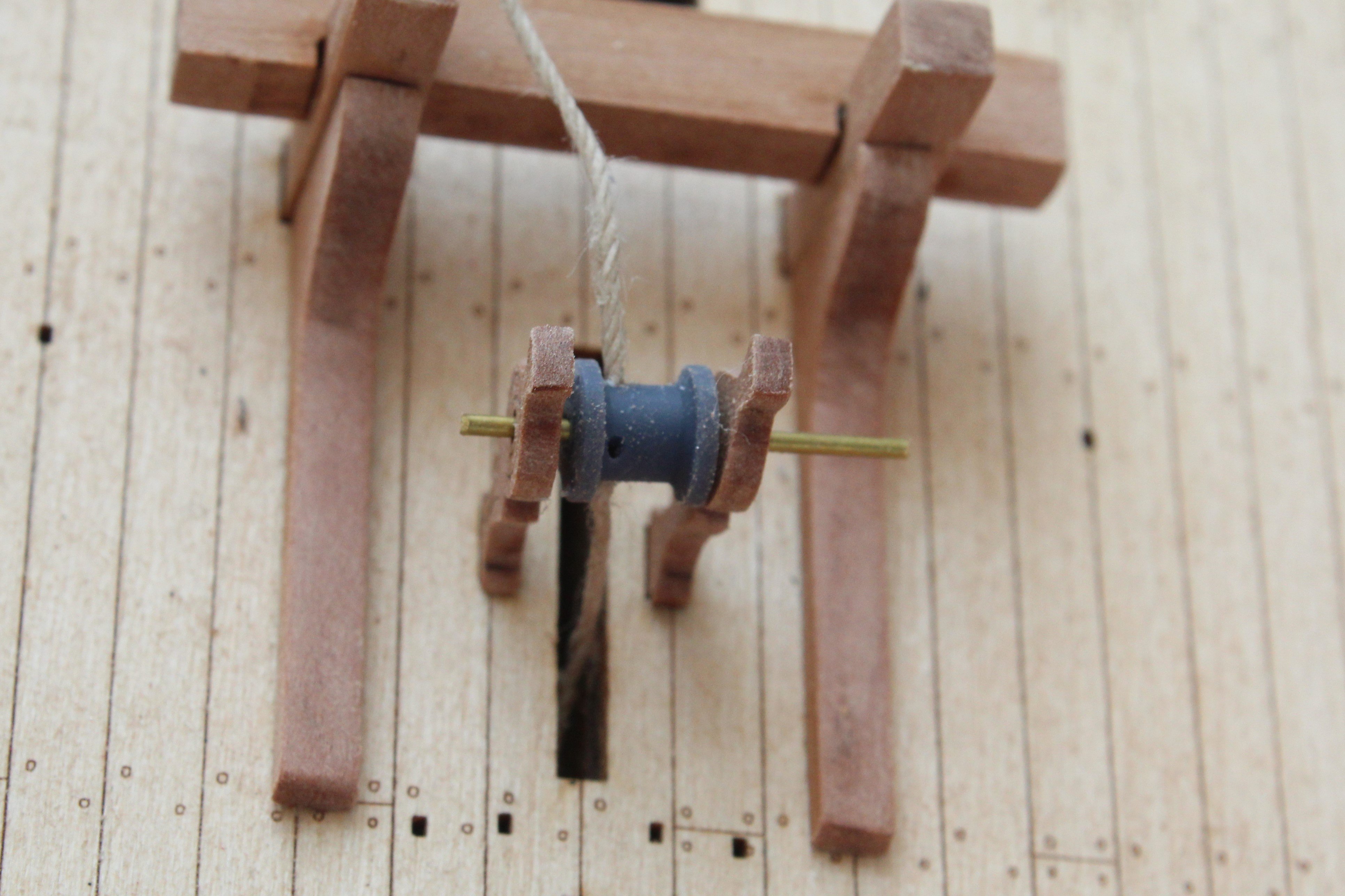
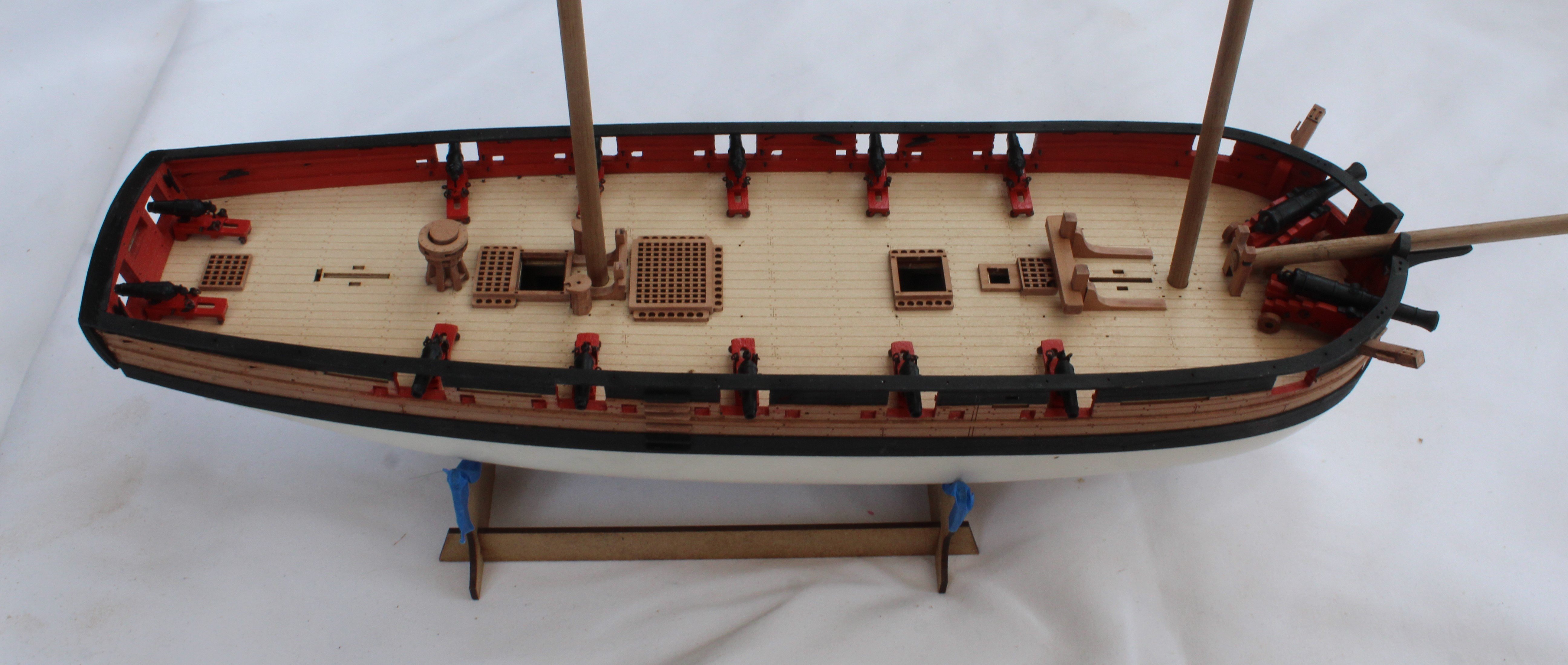
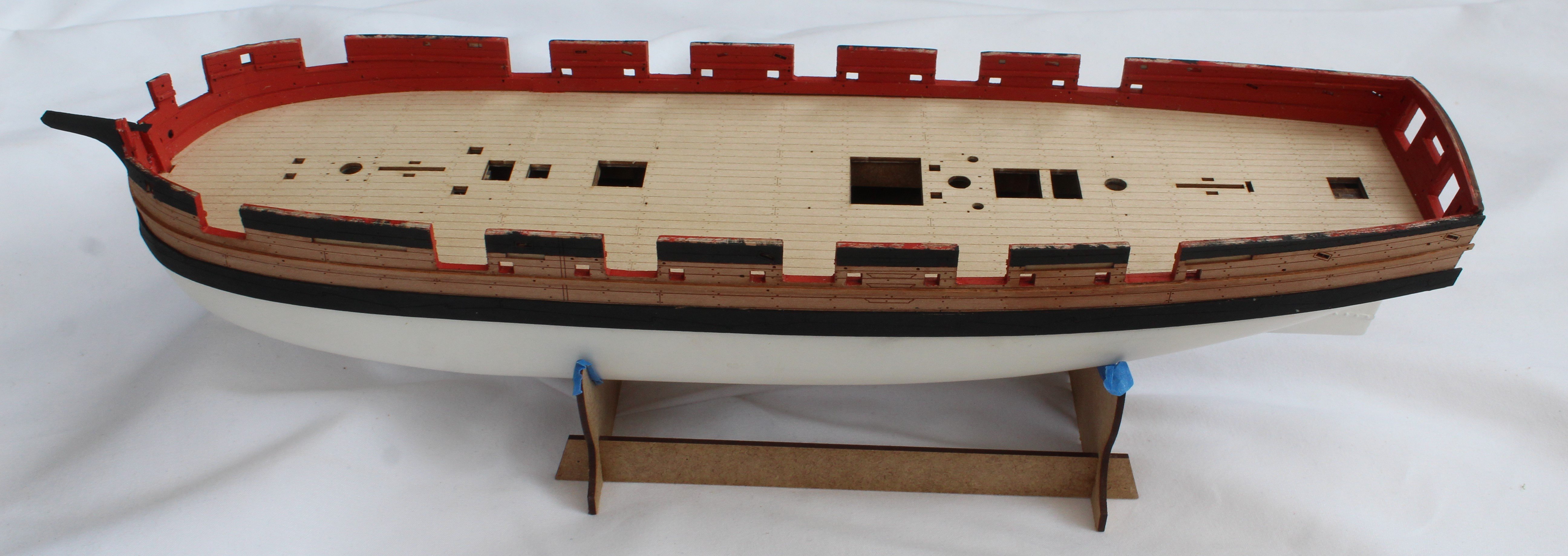
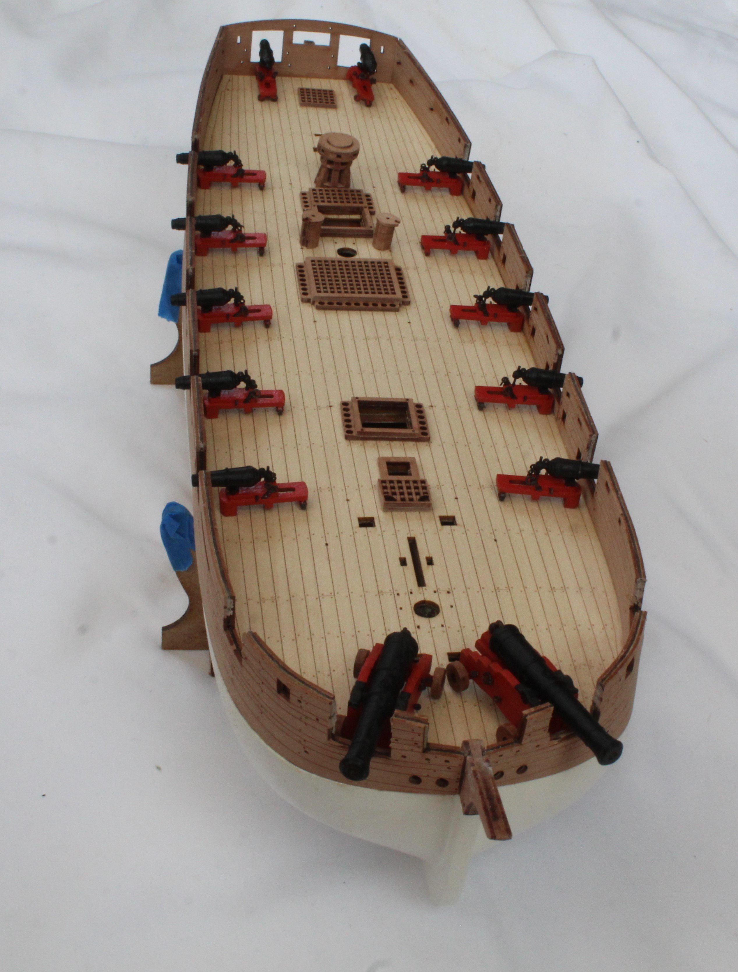
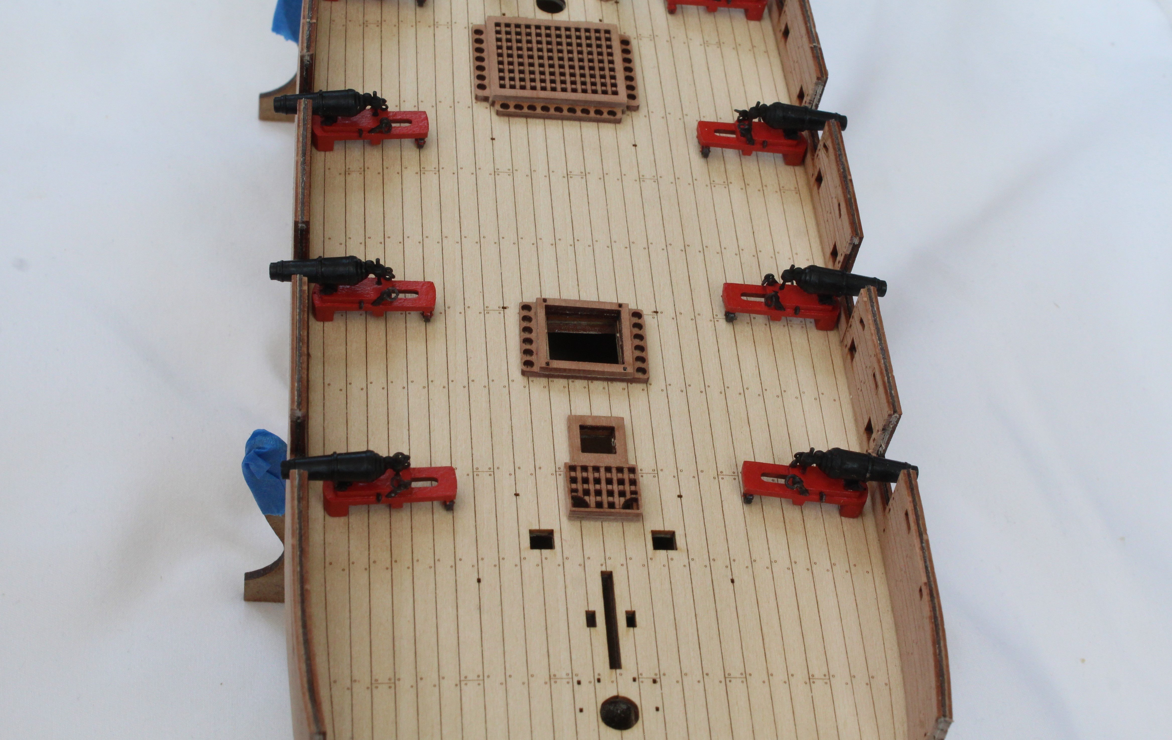
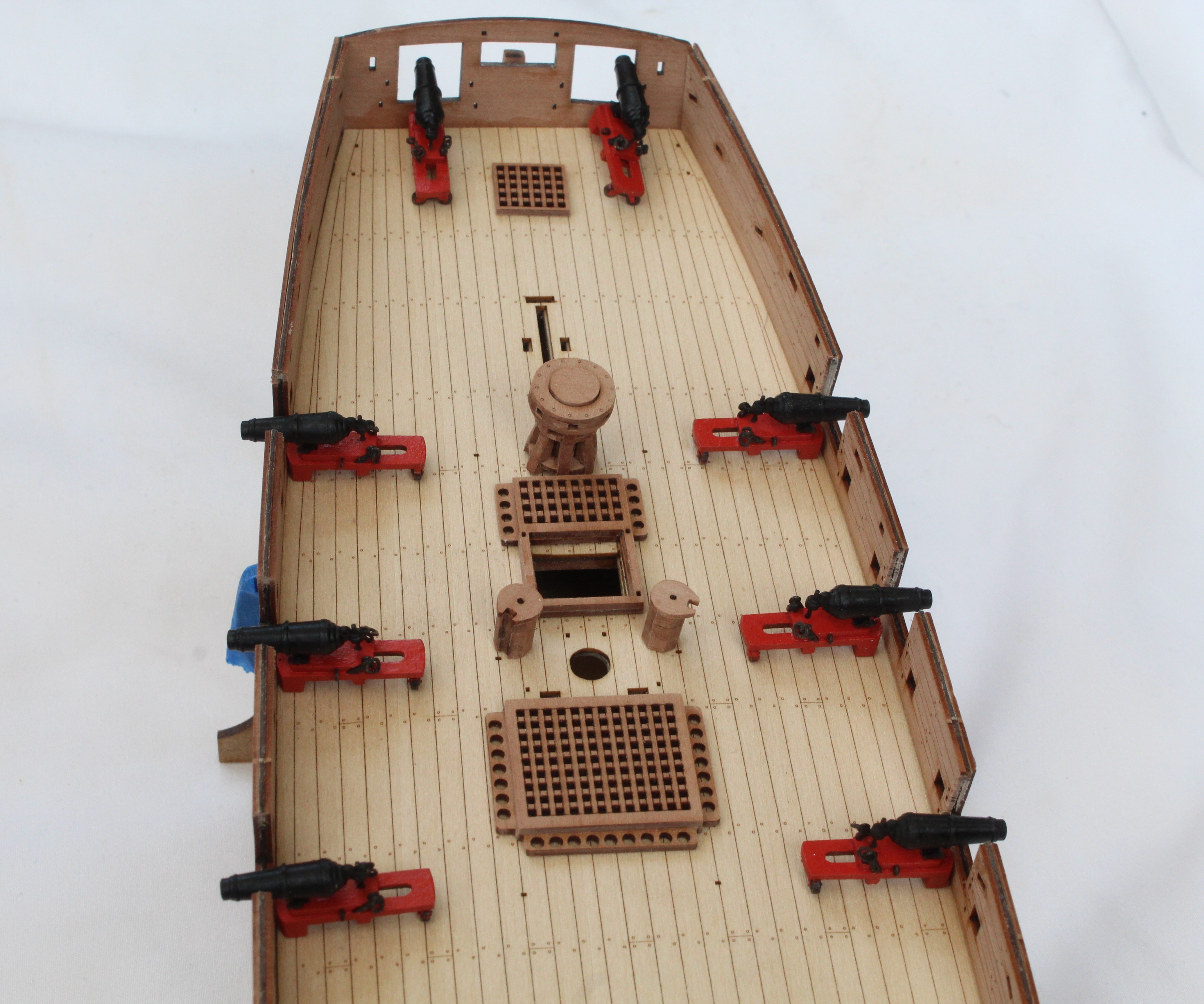
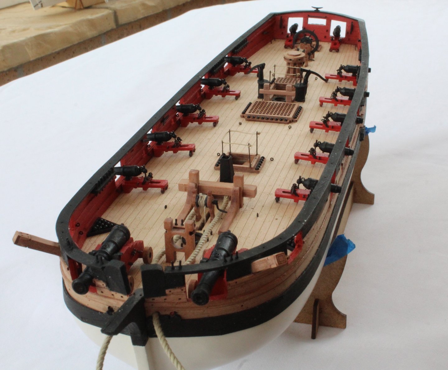
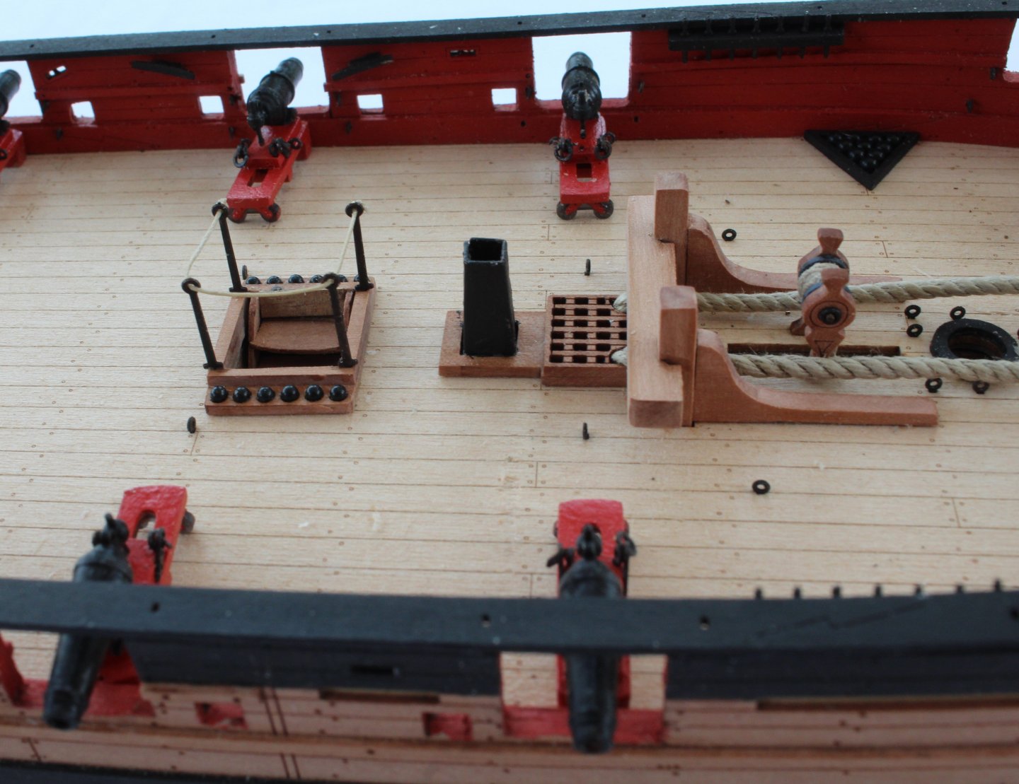
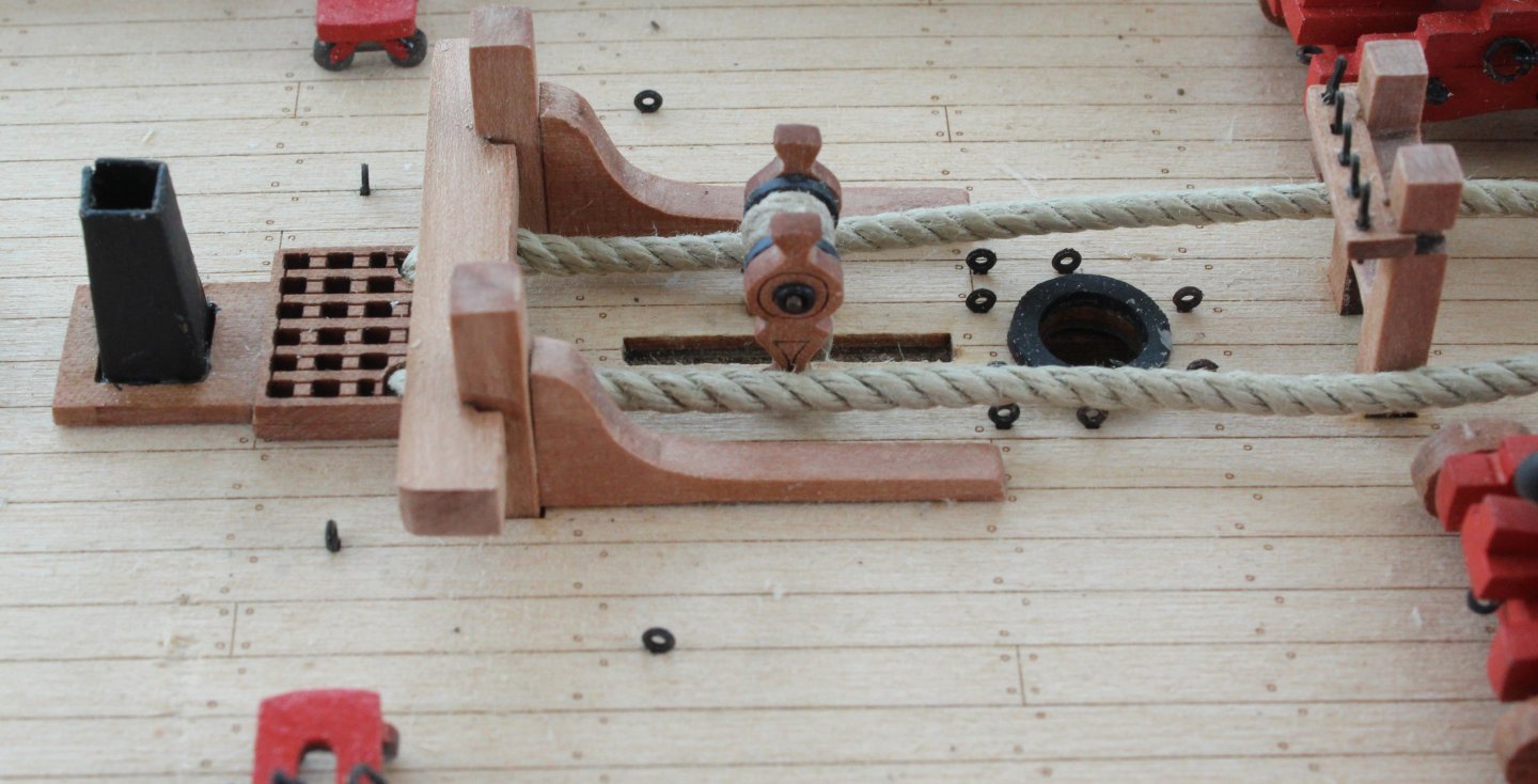
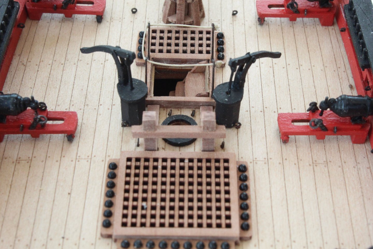
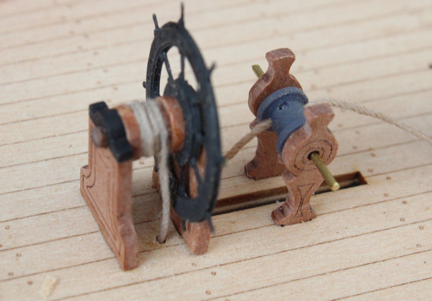
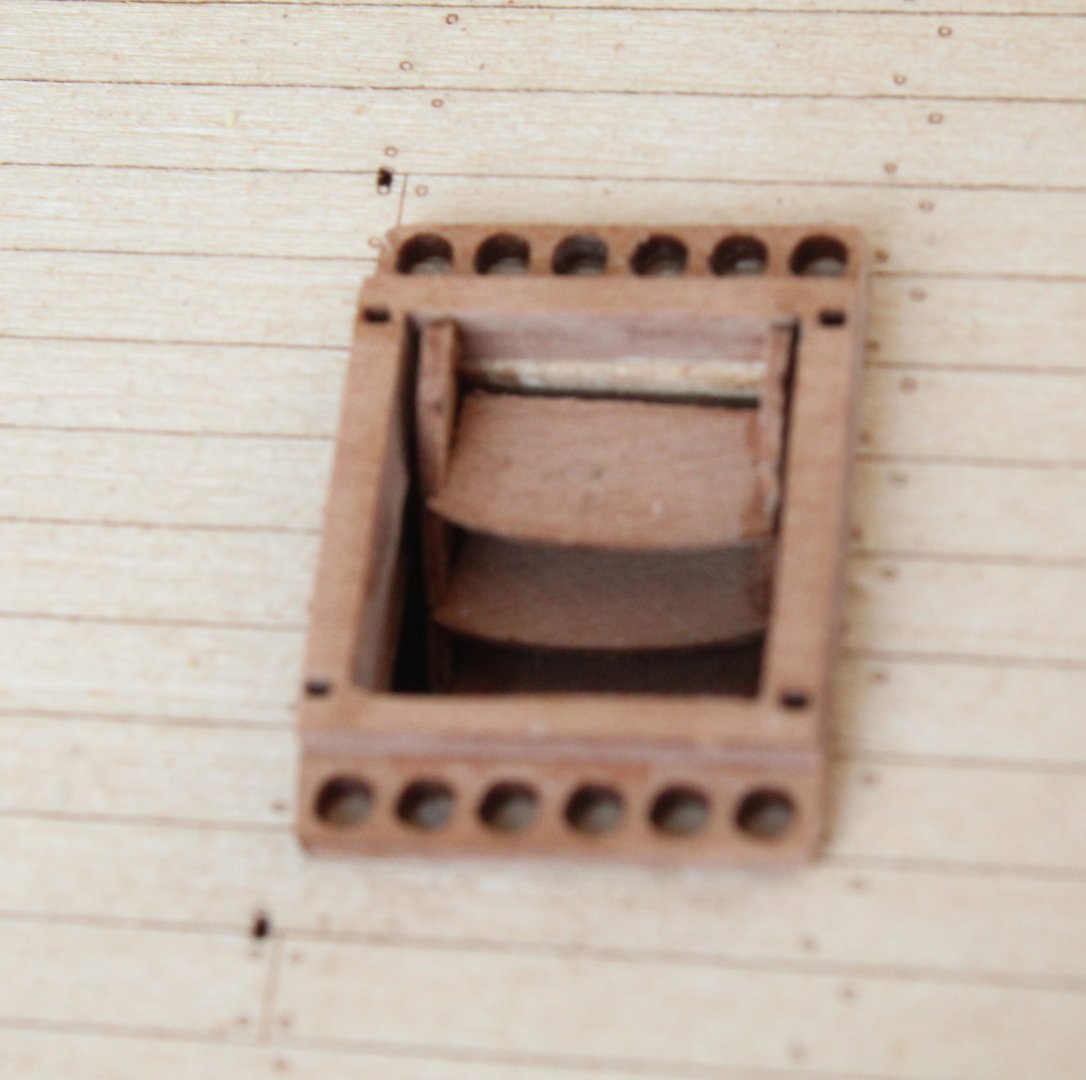
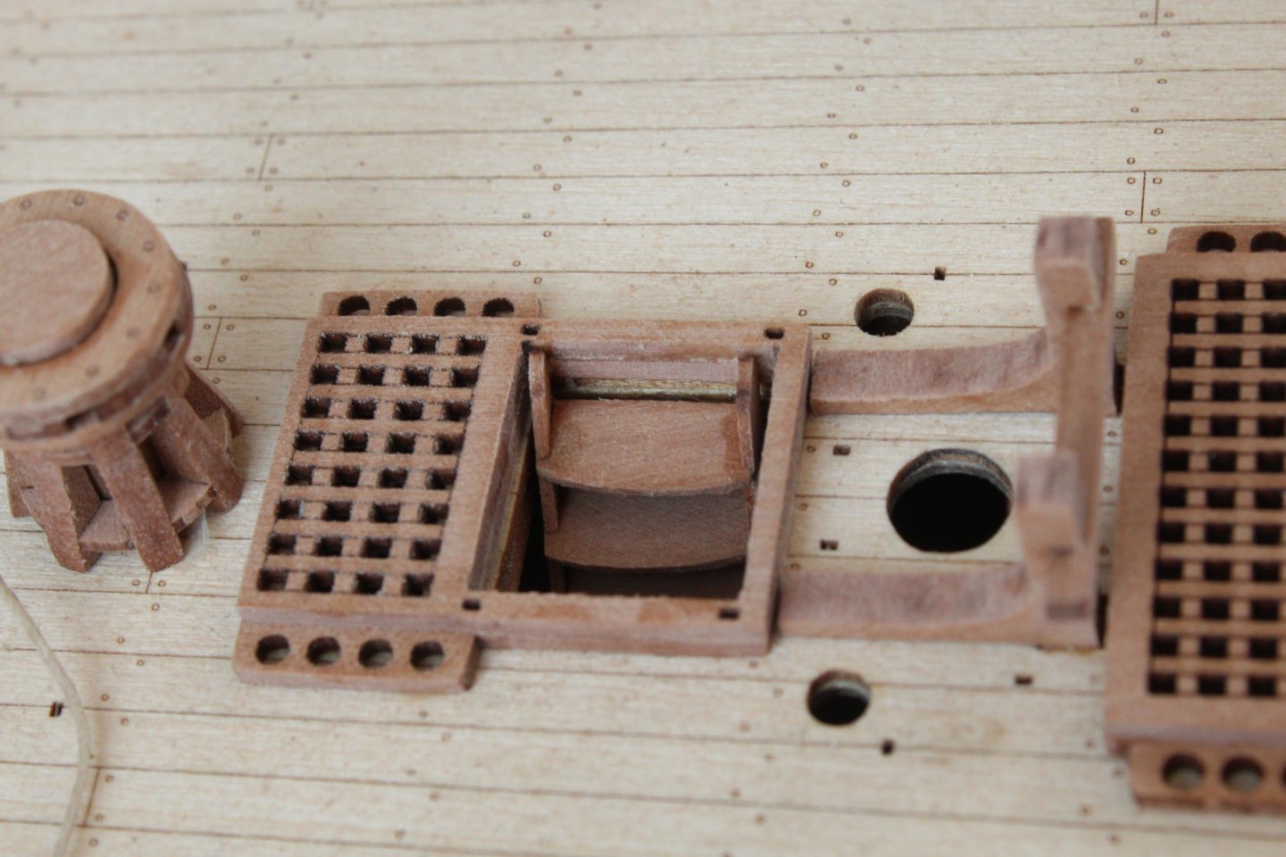
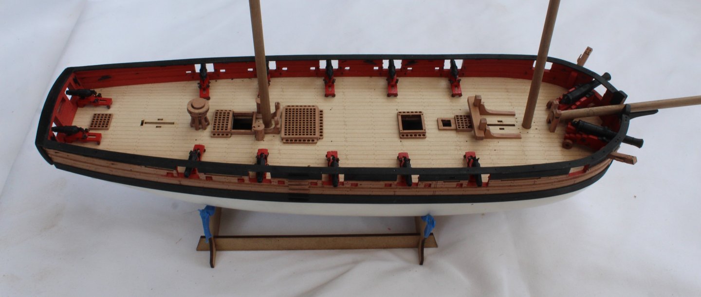
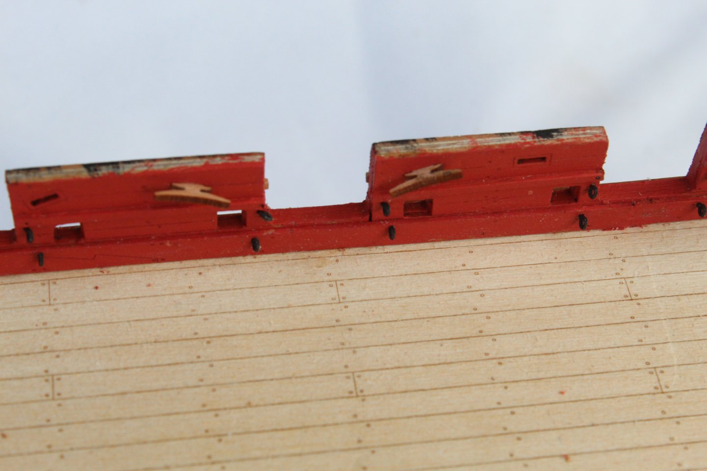
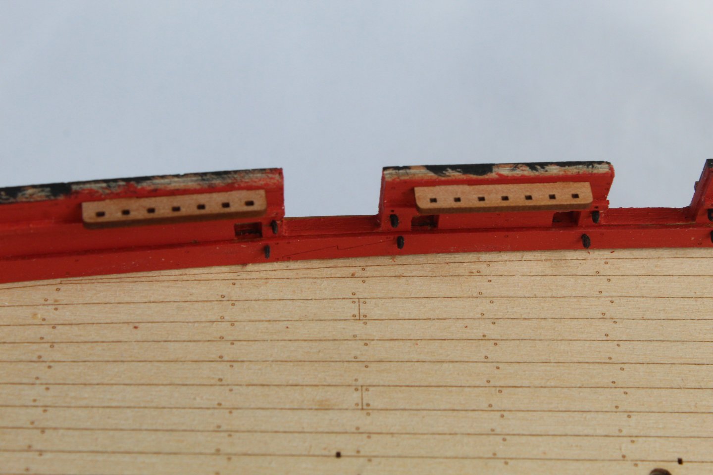
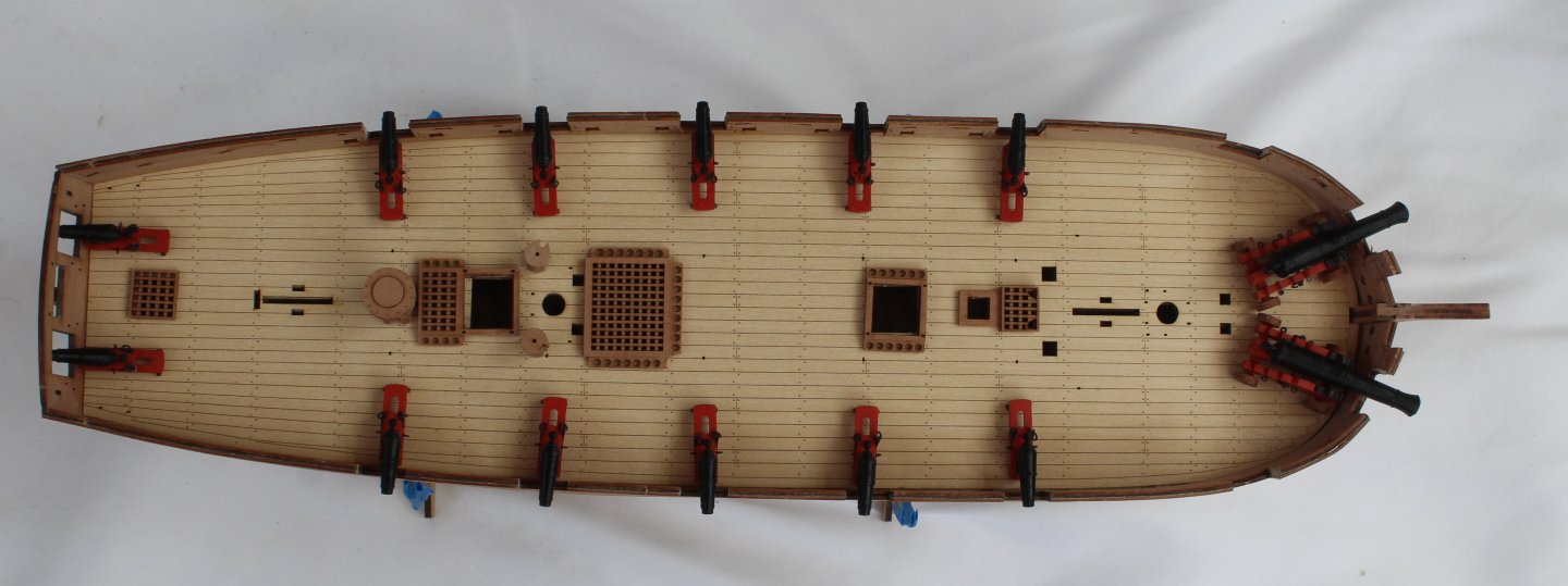
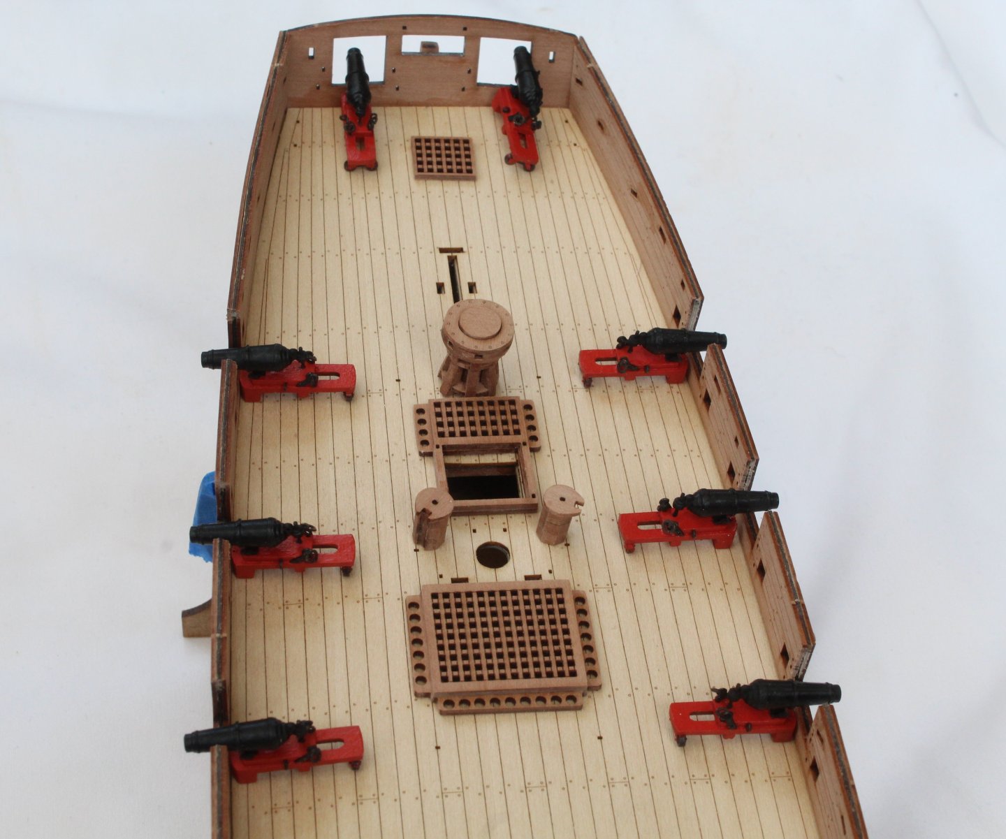
Build Log Index Date: 29/08/2024 Time worked today: 7 hours. Total time spent on build: 60 hours. Hand Pumps, Drop Keel Winches, Belay Pin Racks and Forward Hatch Over the last three days I have completed all the deck work, except for assembled carronades and cannons as I am still debating whether to add the breach rope rigging. In the attached photos I have included carronades and cannons but they have not been glued to the deck. I have also add the eyebolts and mast rings to the deck. Starting with the hand pumps the various PE parts were chemically blackened. Using pins to help with the alignment the pumping mechanisms were assembled and then added to their pump bodies which was also painted black. The two completed assemblies were then added to the deck. The two drop keels were painted, as shown in the build manual. Next eyebolts, complete with the length of 0.5mm thread were added to each drop keels. The threads were run through a block of beeswax a couple of times. I then used a hairdryer to melt the beeswax. To add a bit more rigidity to thread I ran it through a very diluted wood glue solution and dried off with the hairdryer. The free end of each thread was then fed through the hole in their respective winch drums. With each drop keel winch assembly in place on the deck the drop keel position were set, and the threads were then wrapped around their drum and the excess thread trimmed. The two assemblies were then glued to the deck. The 6 off belay pin racks were painted black. The PE belay pins were chemically blackened and then added to the racks. The racks were then added to the inner bulwarks. I also added the shot garlands complete with shots. The stove chimney was chemically blackened, folded and added to the forward hatch. The two anchor ropes was then added to the forward hatch. The completed hatch assembly was then glued to the deck. The anchor ropes were fed through the nearest hawse holes to the stem post. Rudder, Tiller and channels next on the build agenda.


-
Hello Dan You have done a fantastic job your Adder looks great. Well done. Glenn
- 143 replies
-
- 4
-

-
- Adder
- Vanguard Models
- (and 1 more)
-
Plan 6 would make more sense. I did not look at the plan sheet and relied on the photo in the instruction manual for the alignment. I wonder which way is correct? @chris watton
-
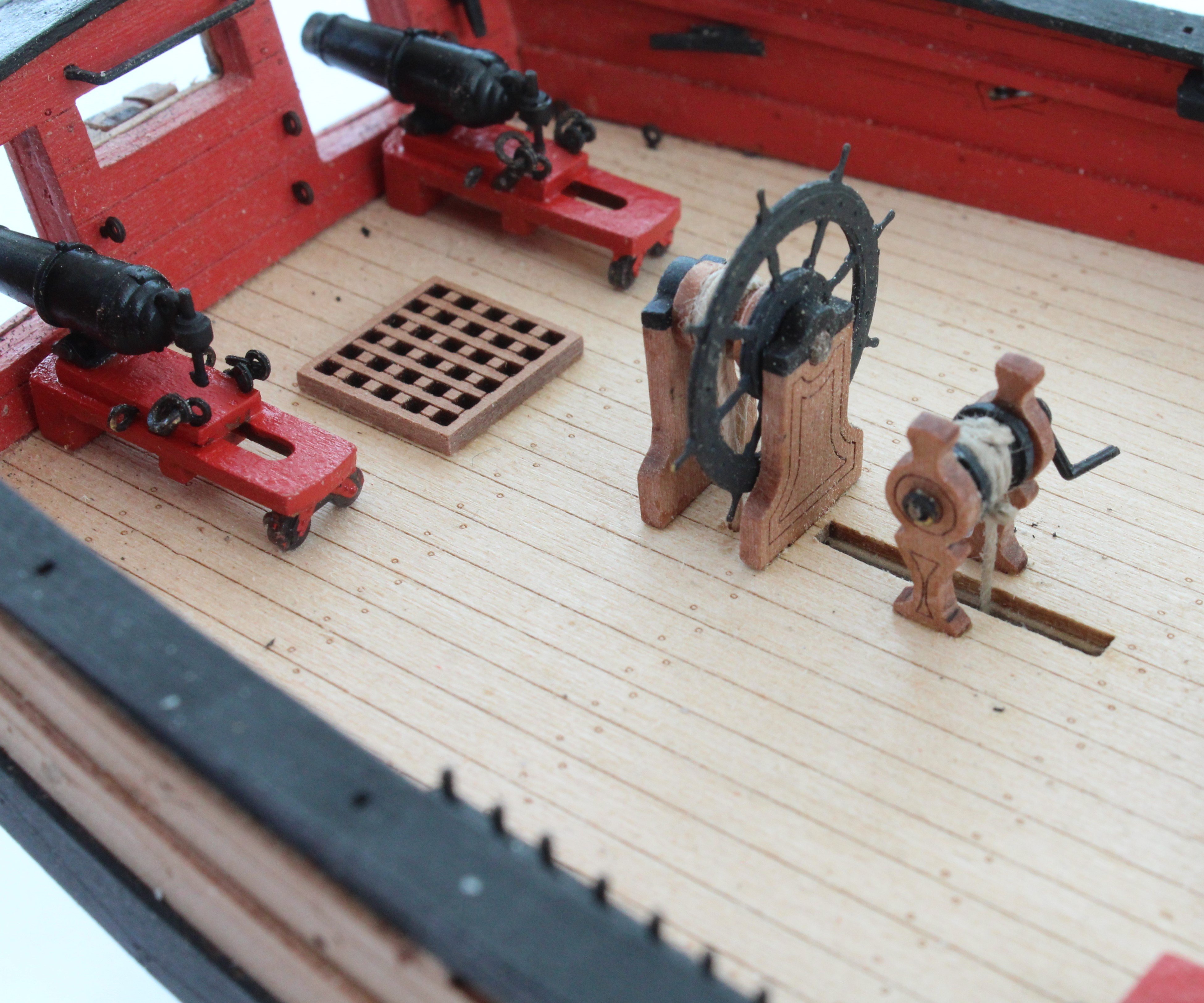
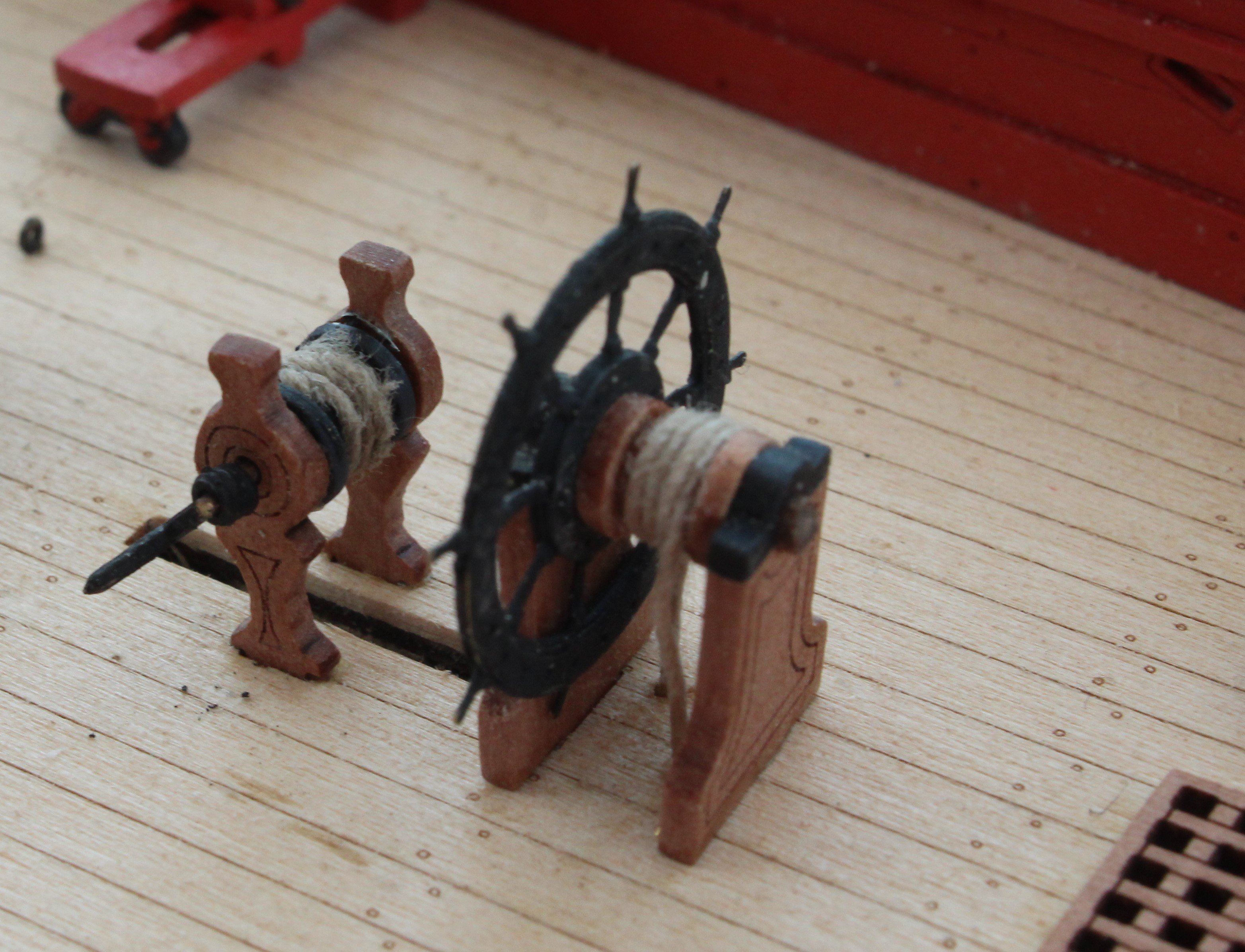
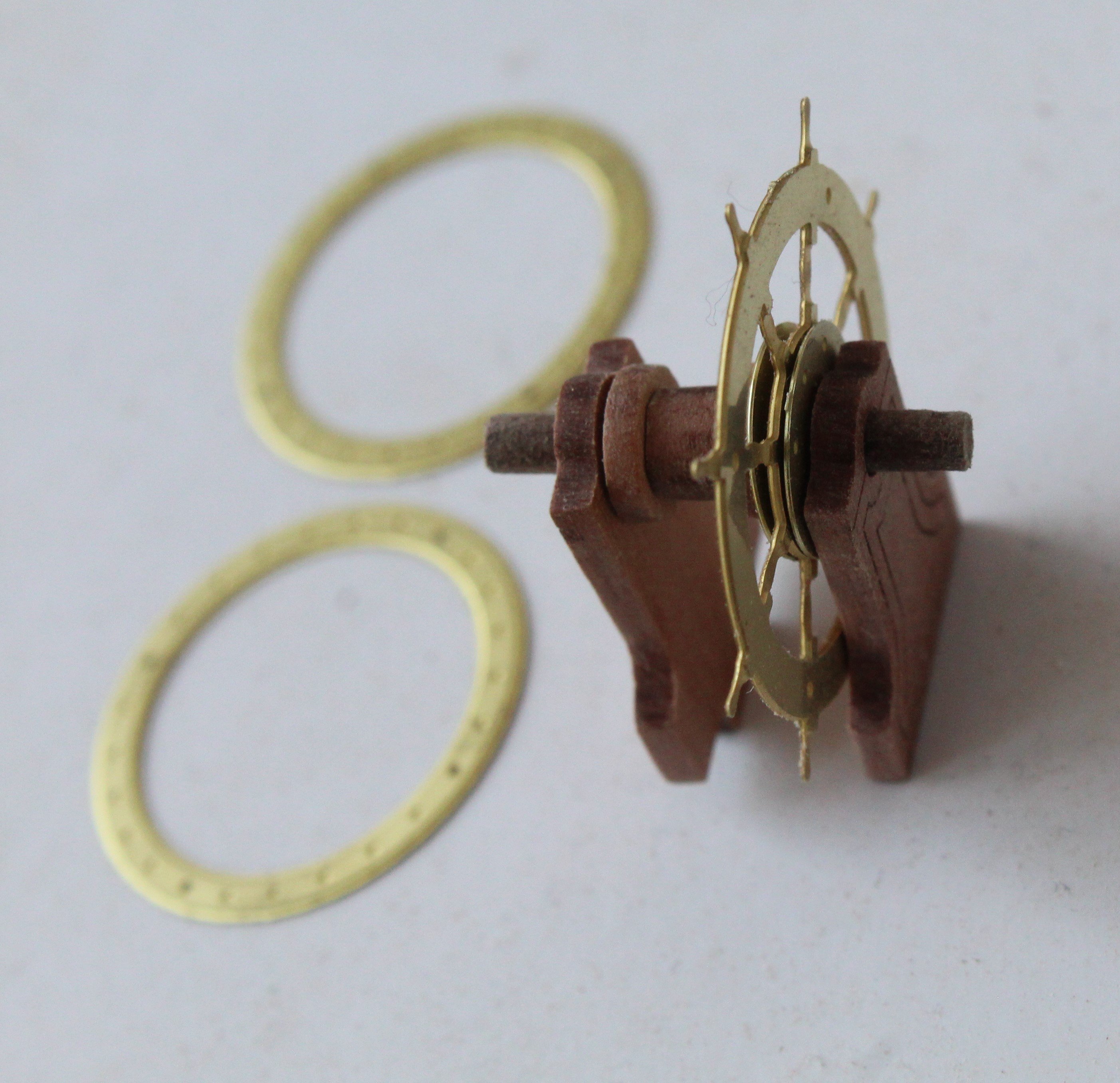
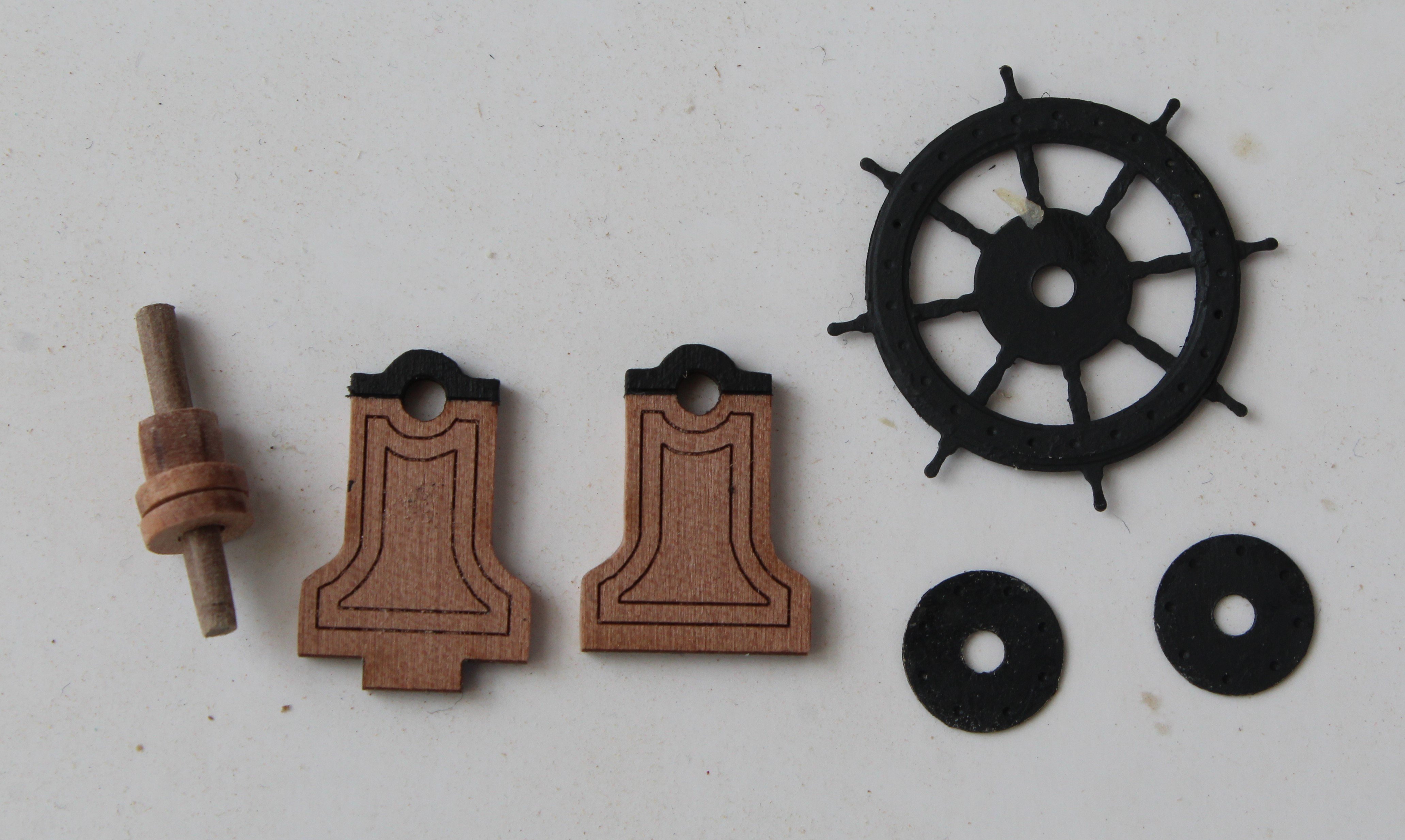
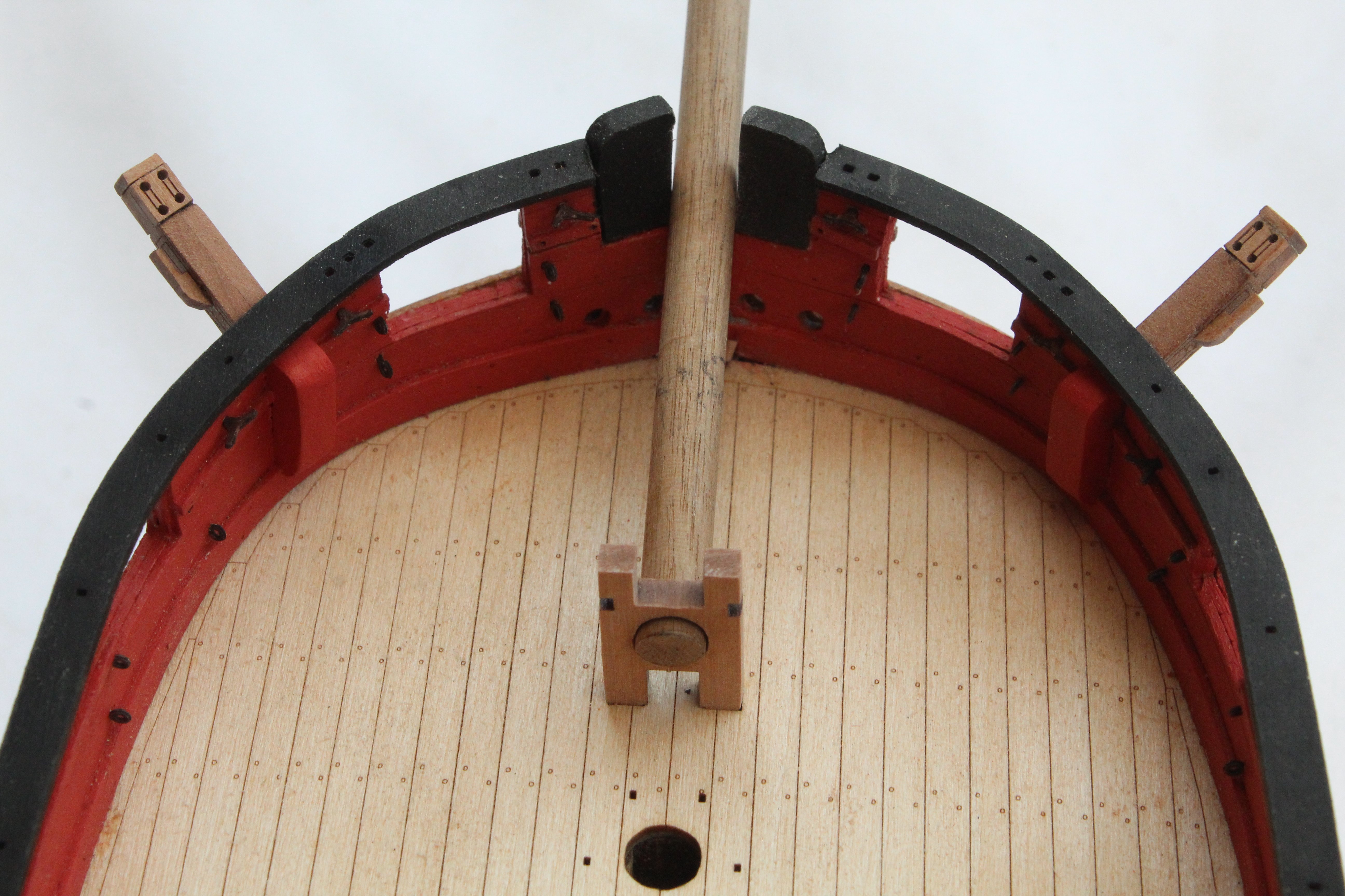
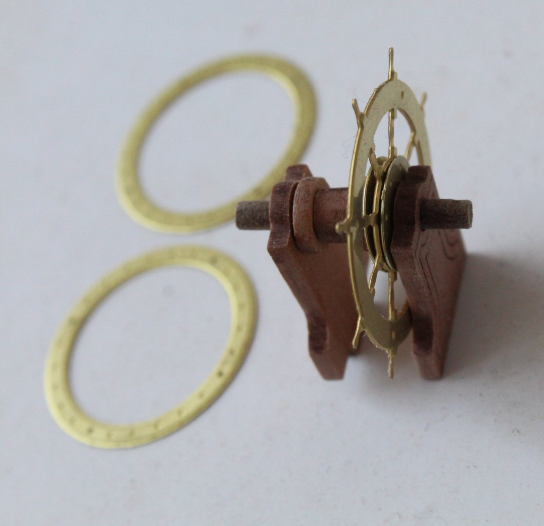
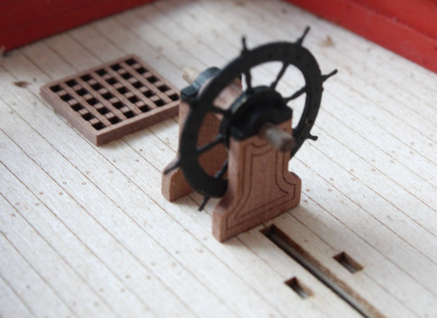
Build Log Index Date: 26/08/2024 Time worked today: 3 hours. Total time spent on build: 53 hours. Hawse Hole Bolster, Ships Wheel, Drop Keel Winch and Ladders First task today was to paint and then glue the two off hawse hole bolster to the hull. Next task was to build and fit the ships wheel. There are several parts required for the ships wheel. After removing the laser char a test assembly was undertaken. The next task was to paint the parts. I opted for a smoke black colour for the wheel assembly and black for the tops of the ships wheel side frames. Next a dry fit of the ships wheel assembly on the deck. The 2mm dowel needs to be trimmed. After trimming the dowel and then adding the thread the ships wheel was added to the deck. You will also note that I am in the process of test fitting the aft drop keel winch. I have also done a test fit of the forward drop keel winch. The final task of the day was to add the two ladders.


-
Thanks Andrew
-
Thanks Bob I am happy with the build so far.
-
Thanks, and the photos make the niggles look much worse than it looks to the naked eye. I agree with the position of the 24 pounders, it will be a few days before I actually fix them in place.
-
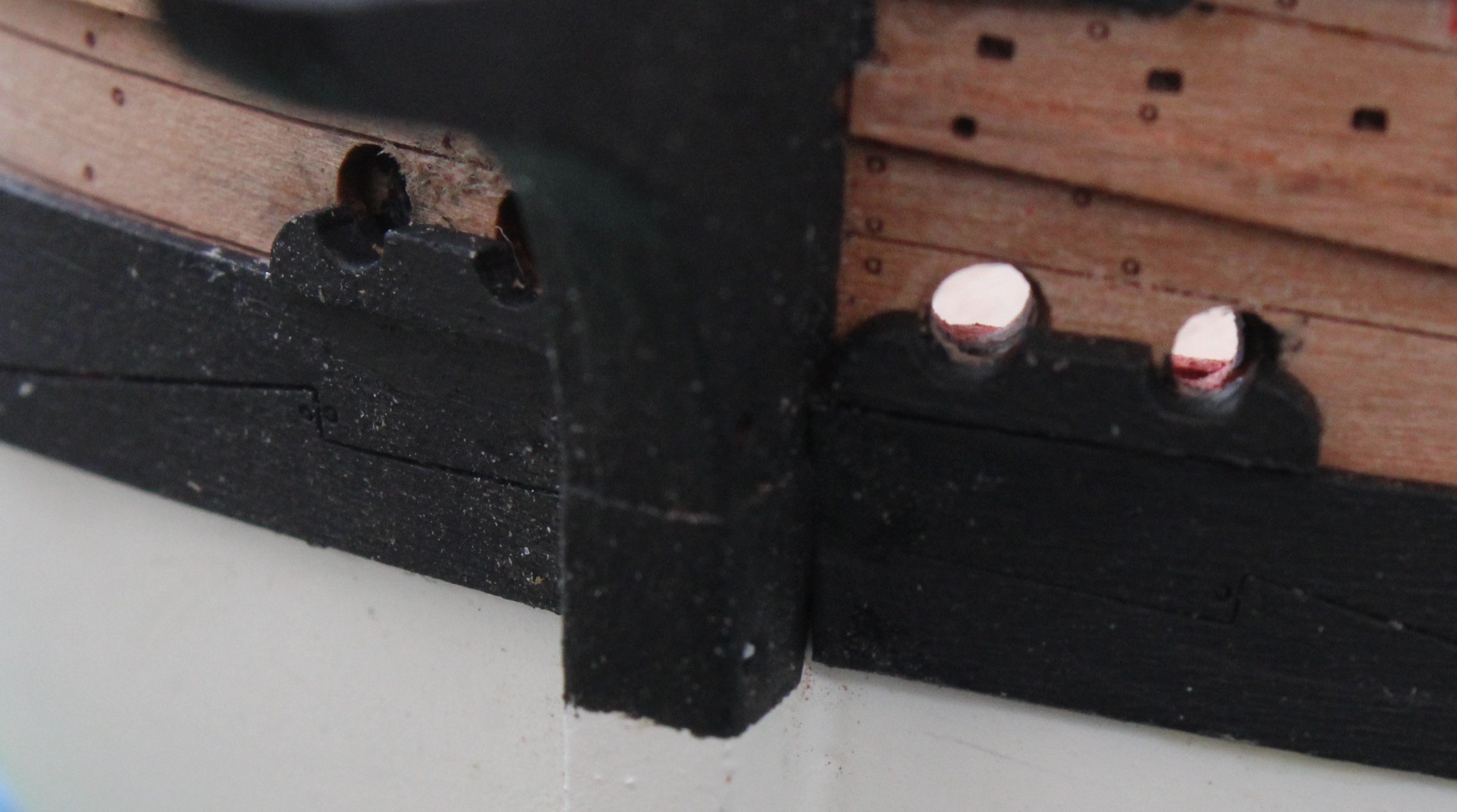
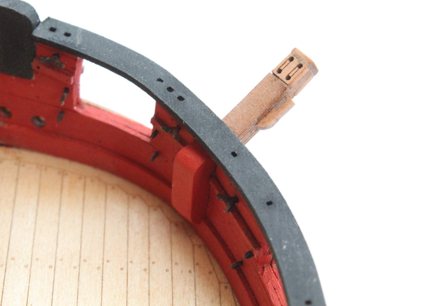
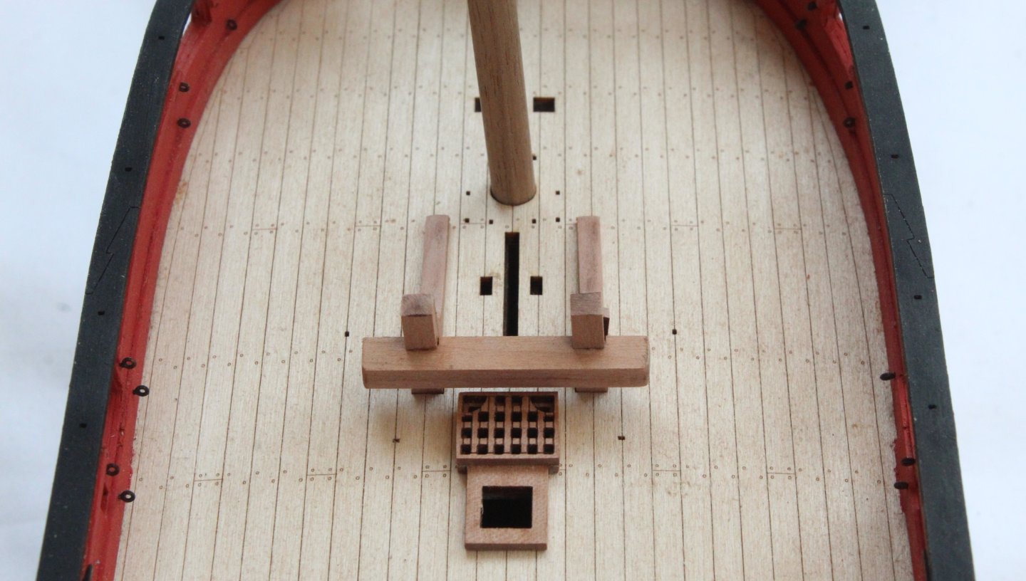
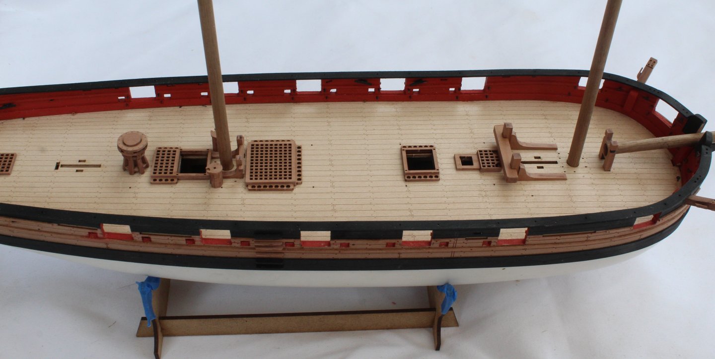
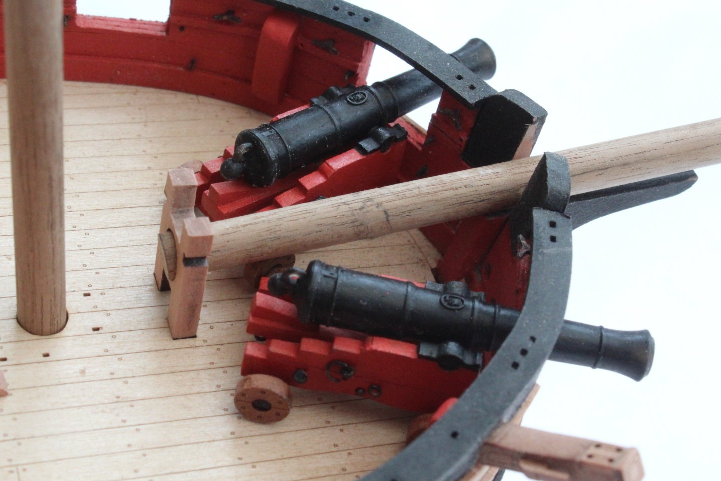
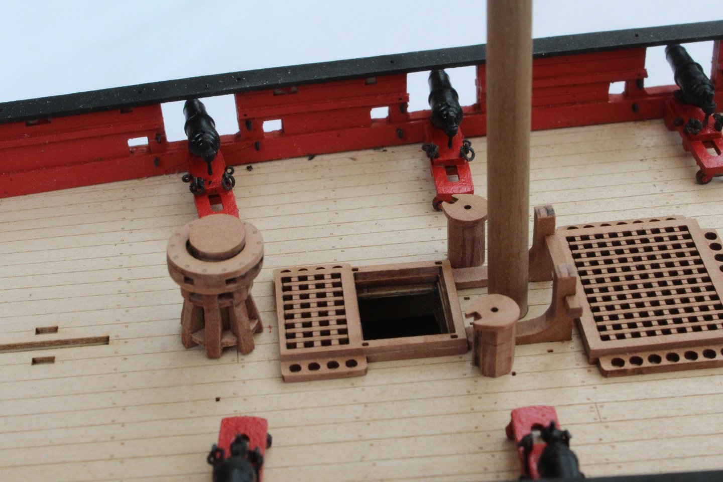
Build Log Index Date: 25/08/2024 Time worked today: 2 hours. Total time spent on build: 50 hours. Steps, Stern Surround Pattern and Catheads The most time-consuming task today was the assembly of the 12 steps. Each step is a two-part assembly. With all the parts removed from the sheet the laser char was removed. Using wood glue each step was assembled, taking great care that the two parts were correctly aligned with each other. It was then as simple task to fix the steps to the hull using wood glue. After a trial fit of the stern surround pattern the part was brushed with a coat of varnish followed by two coats of black paint. Using wood glue the stern surround pattern was then added to the outer face of the stern board. The back end of the gunwales (right side) does not look that good in this photo. I might tweak this at some point. Using a triangular bladed file the gap for the catheads were opened up. A micro drill was run through the each of the cathead rigging holes, so I do have the option of using them when fitting the anchors. After the catheads were glued in place, using wood glue, the inboard parts were painted flat red to match the bulwarks. The channels have all been test fitted, but I will add them just before I start the rigging phase. As the next phase of the build is to add the various deck items which I have already built I thought it would be a good idea to see how they will look. This is a close up of the bow & bowsprit. A close up of the fore bitt assembly and hatch. Now a photo with the cannons and carronades added. Close up of the bow area with the two cannons. Now a selection of close up photos showing the deck items and carronades.


-
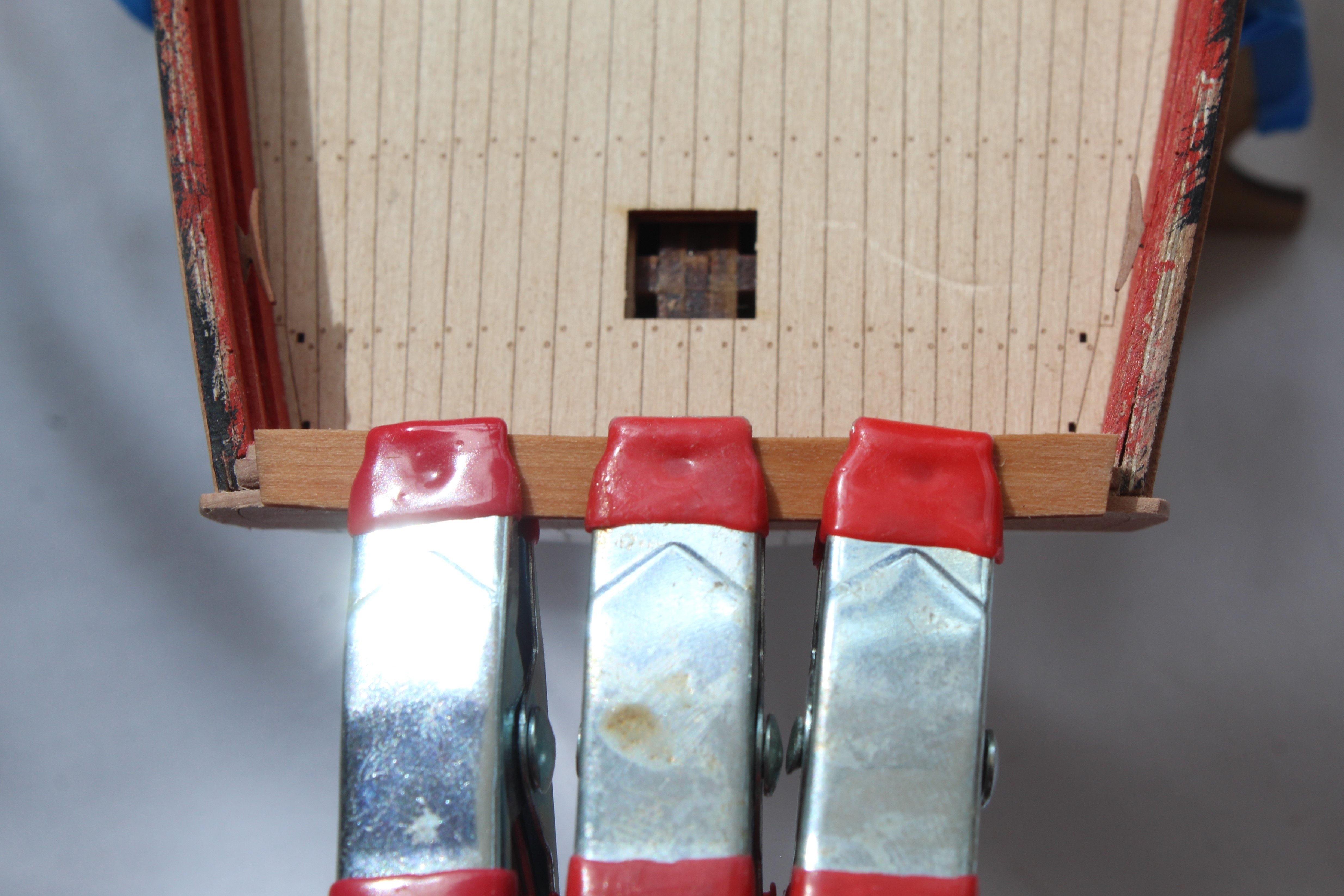
Build Log Index Date: 24/08/2024 Time worked today: 2 hours. Total time spent on build: 48 hours. Gunwales and Bow Timbers After soaking the stern gunwale in hot water for a few minutes I was happy with the fit once the clamps were removed after they had been left to dry overnight. I decided to glue this part in place using wood glue. Once that was done the two gunwale patterns were painted black. I applied a coat of varnish followed by 2 coats of black paint. After a couple of trial fits the gunwale patters were trimmed and then glued in place. I opted to use ca glue for this. Next the two bow timbers were added to the hull after they had been painted black. The various cleats, after being painted black, were also added to the bulwarks. I am considering adding the breach rigging to the various carronades and cannons. I do have an idea how to simplify the production and installation of the breach rigging so I will do a bit of experimentation before making a final decision.


-
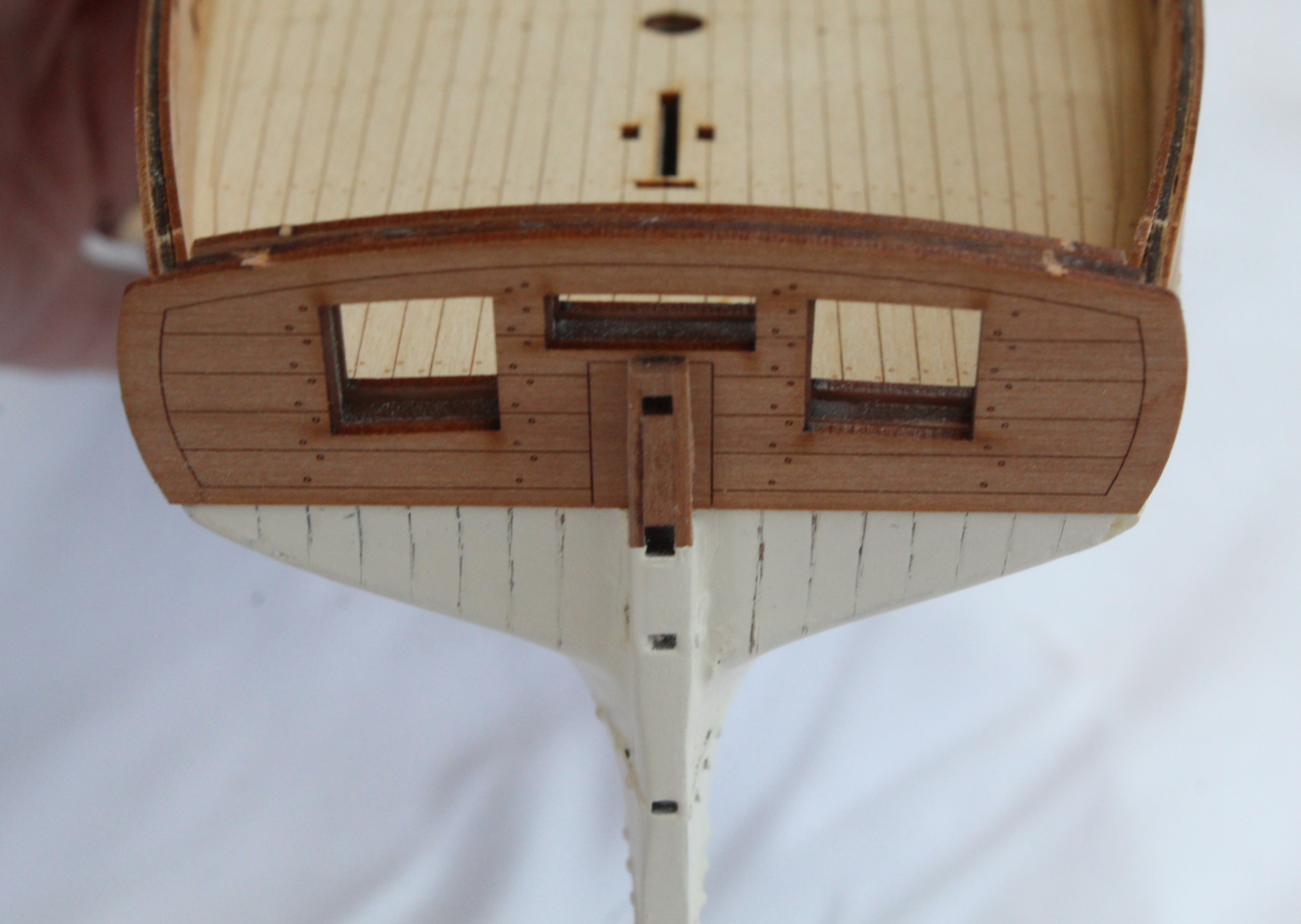
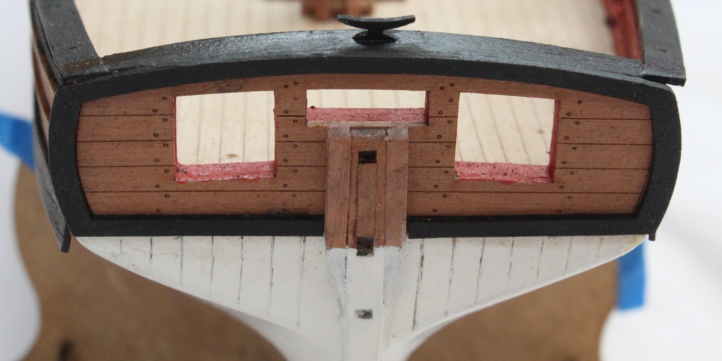
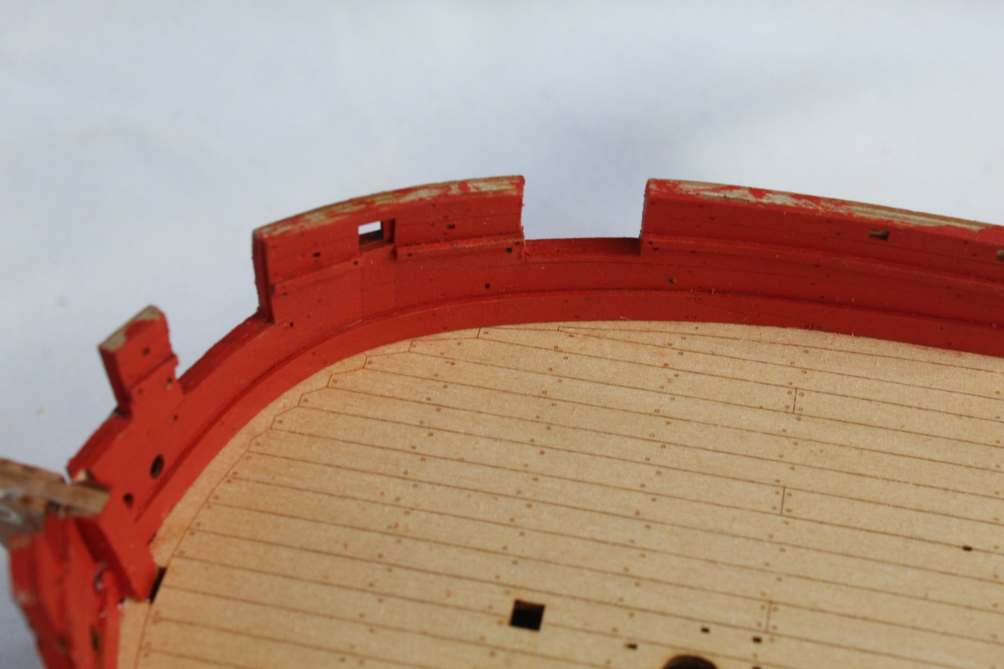
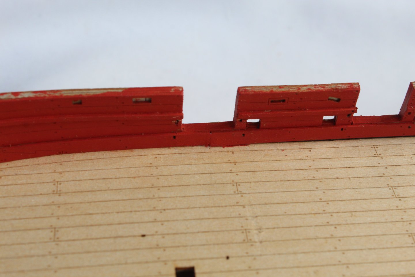
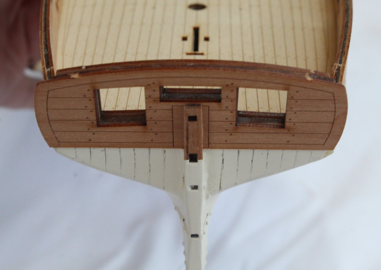
Build Log Index Date: 23/08/2024 Time worked today: 3 hours. Total time spent on build: 46 hours. Carronade Eyebolts and Outer Stern Board The eyebolts which are located on the inner bulwarks for the carronades were chemically blackened. The process I use for this works well and is as follows: a) Soak the PE parts in acetone and agitate the solution for a few minutes b) Transfer the PE parts to a soapy hot water solution. Agitate the solution for a few minutes c) Rinse the PE parts and repeat a) above. d) Rinse the PE parts in hot water and dry. e) Place the PE parts in the blackening solution f) Place the blackened PE parts on a paper towel and pat dry. After fitting all the eyebolts I decided to dry fitted the various internal cleats and belay pin racks. The next task was to fit the Outer Stern Board. Once that was done the two rudder post cheeks were then added. They did need to be trimmed to fit. The lower section of the rudder post cheeks were also painted white to match the hull. The stern gunwale pattern was soaked in hot water for a few minutes and then clamped to the stern board assembly. This will be left to fully dry out before moving on to add all the gunwale patterns.


-
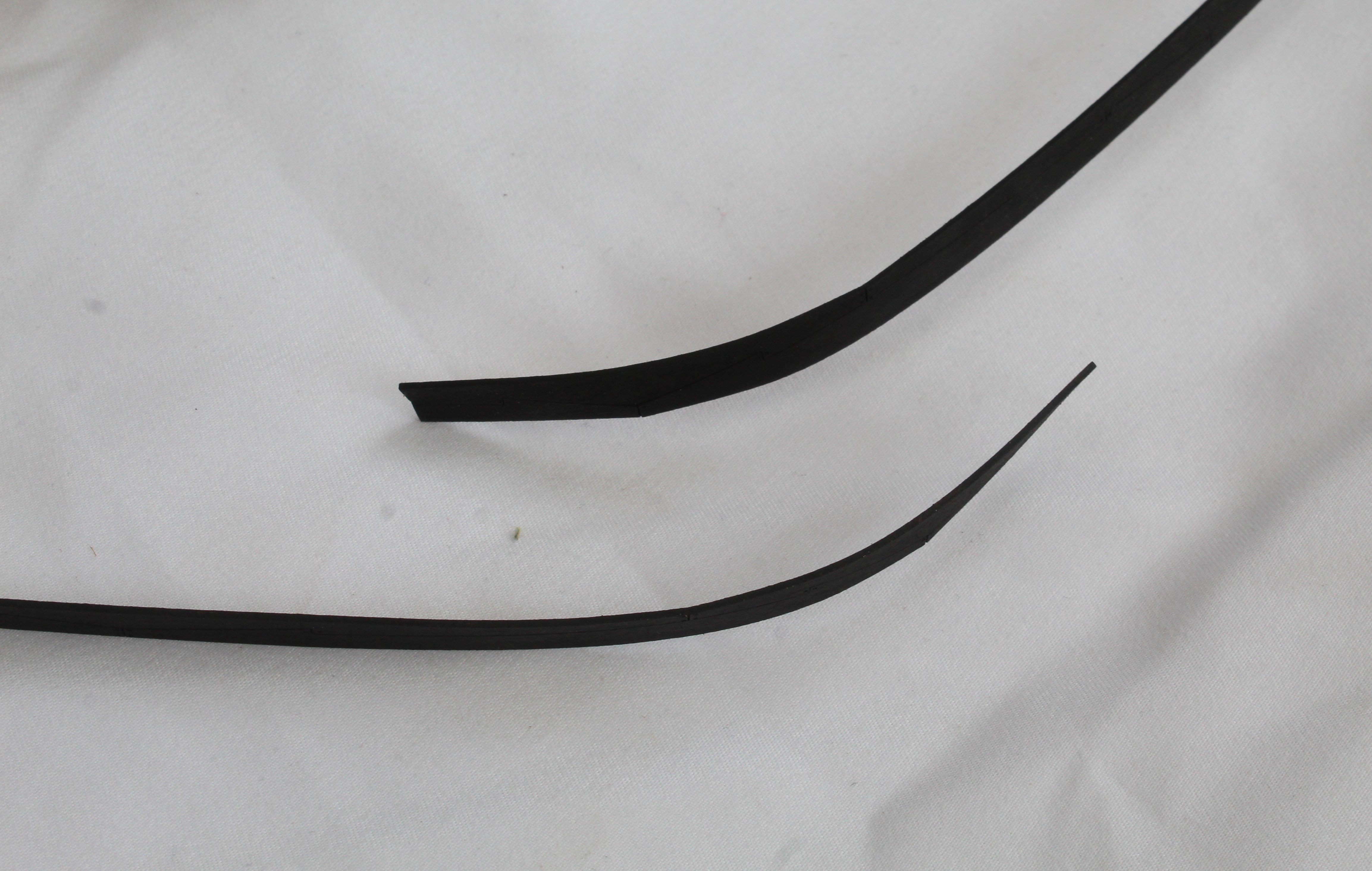
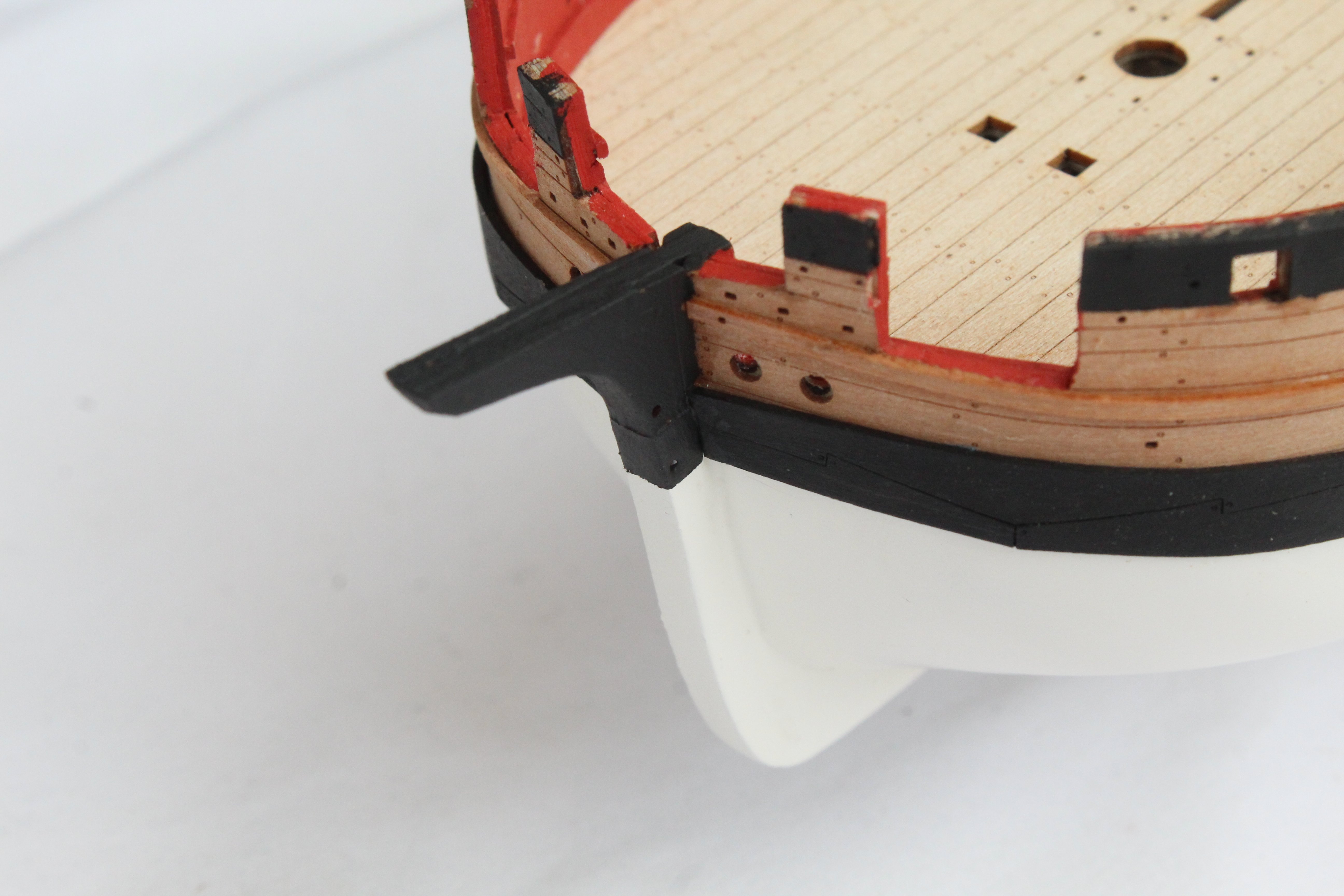
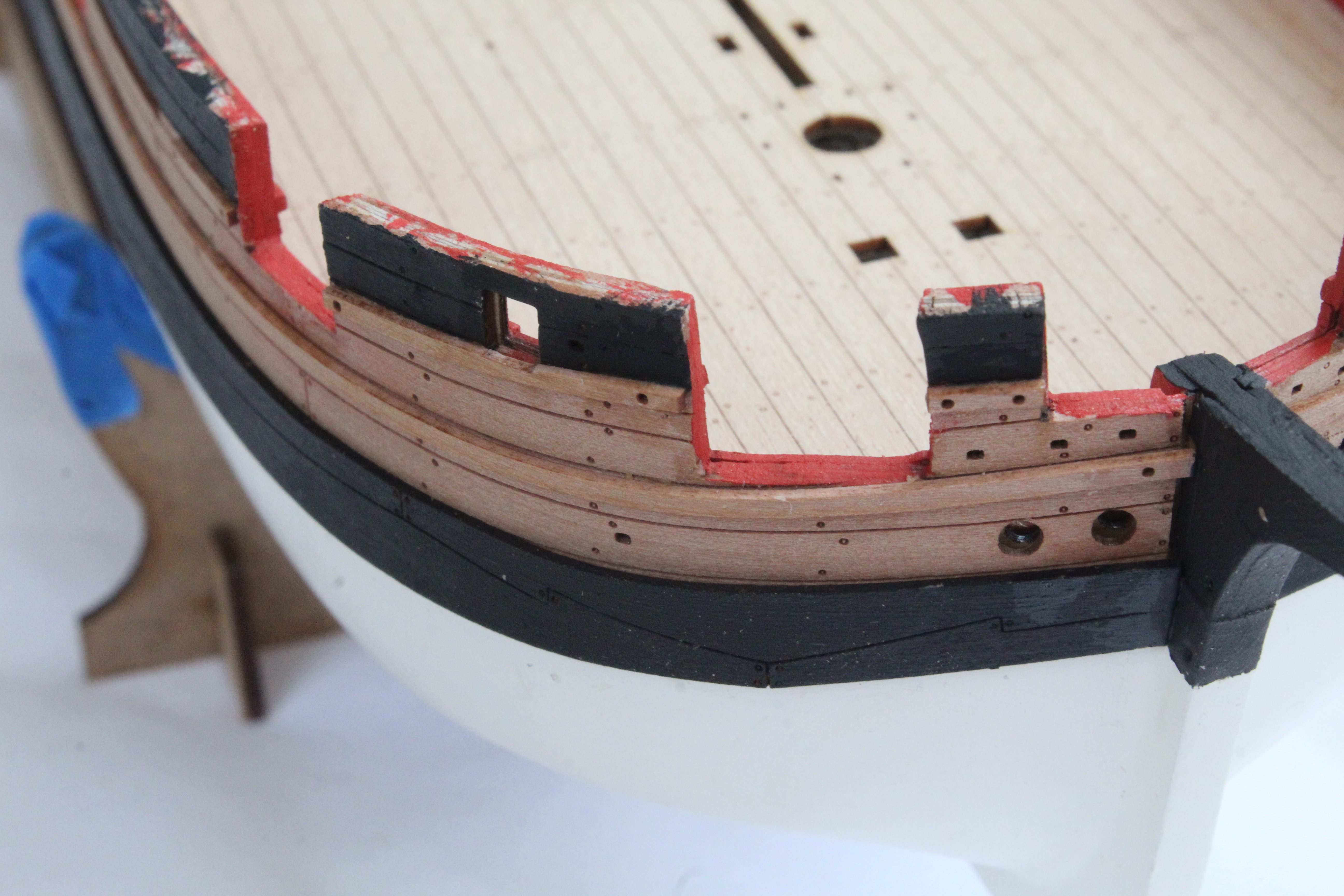
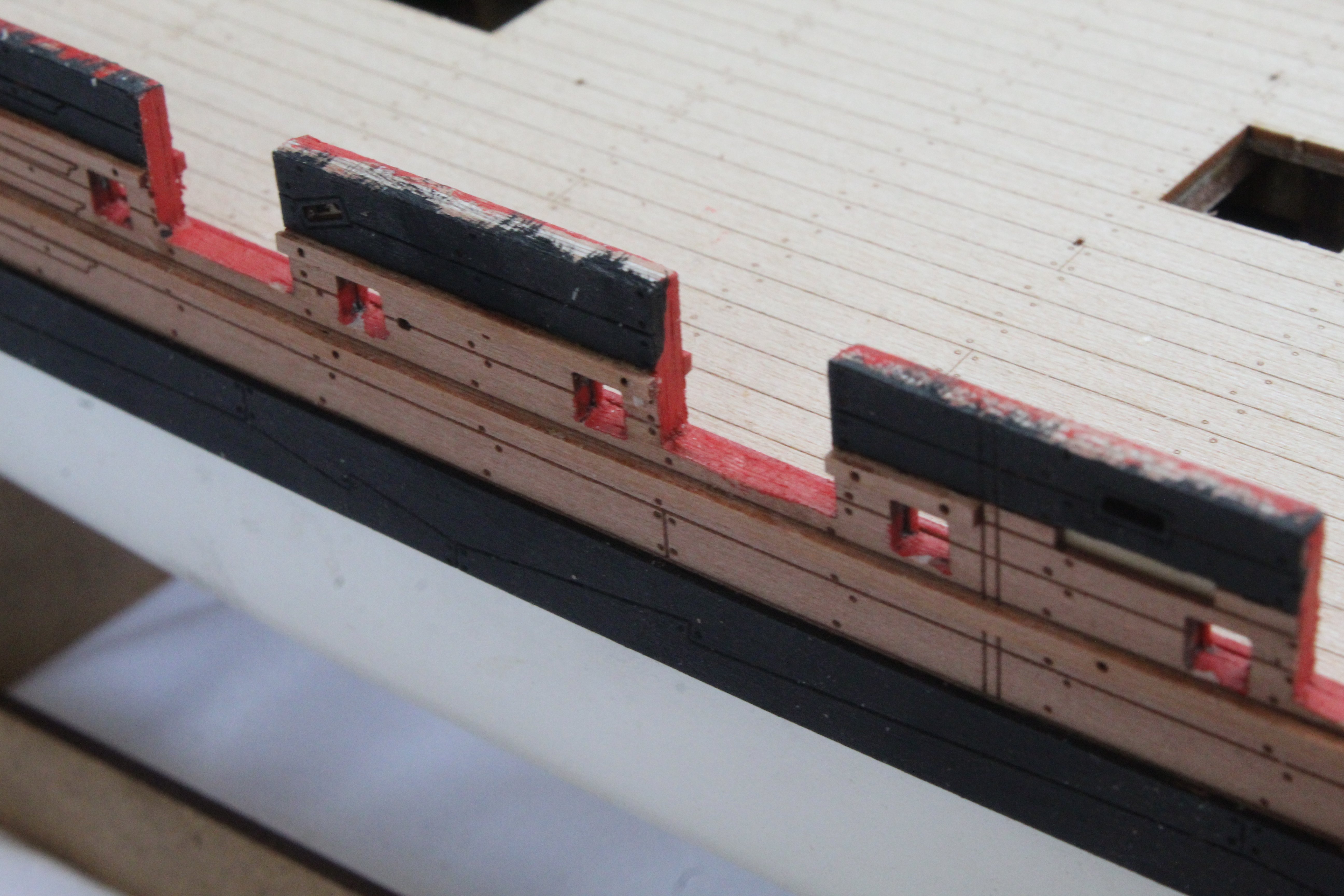
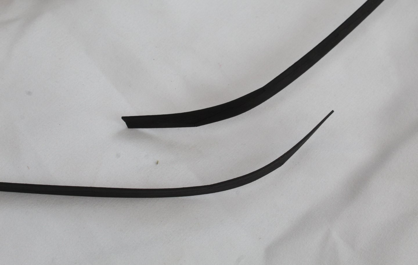
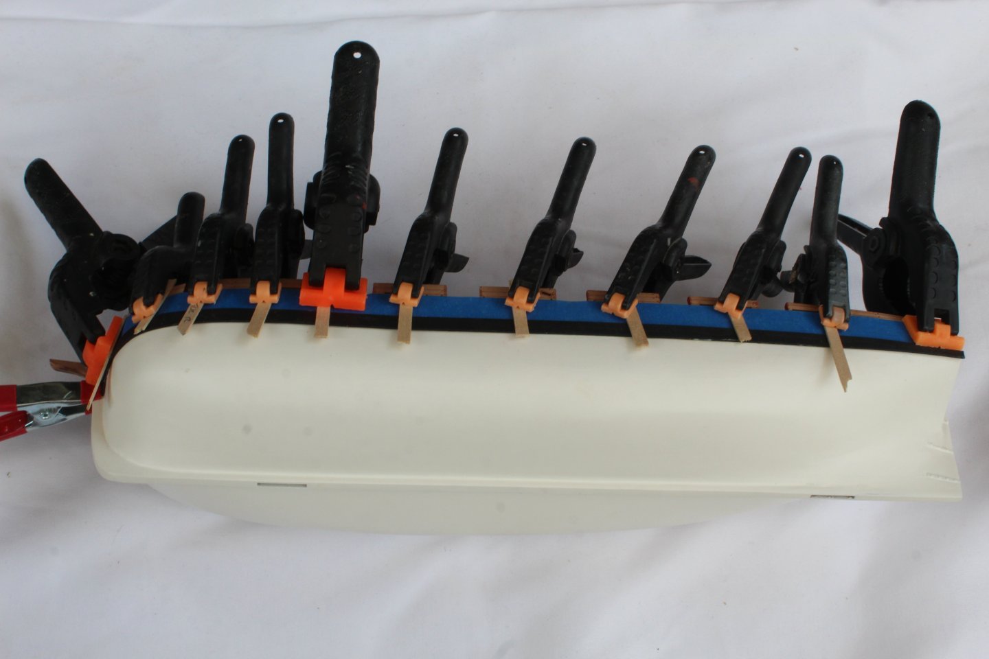
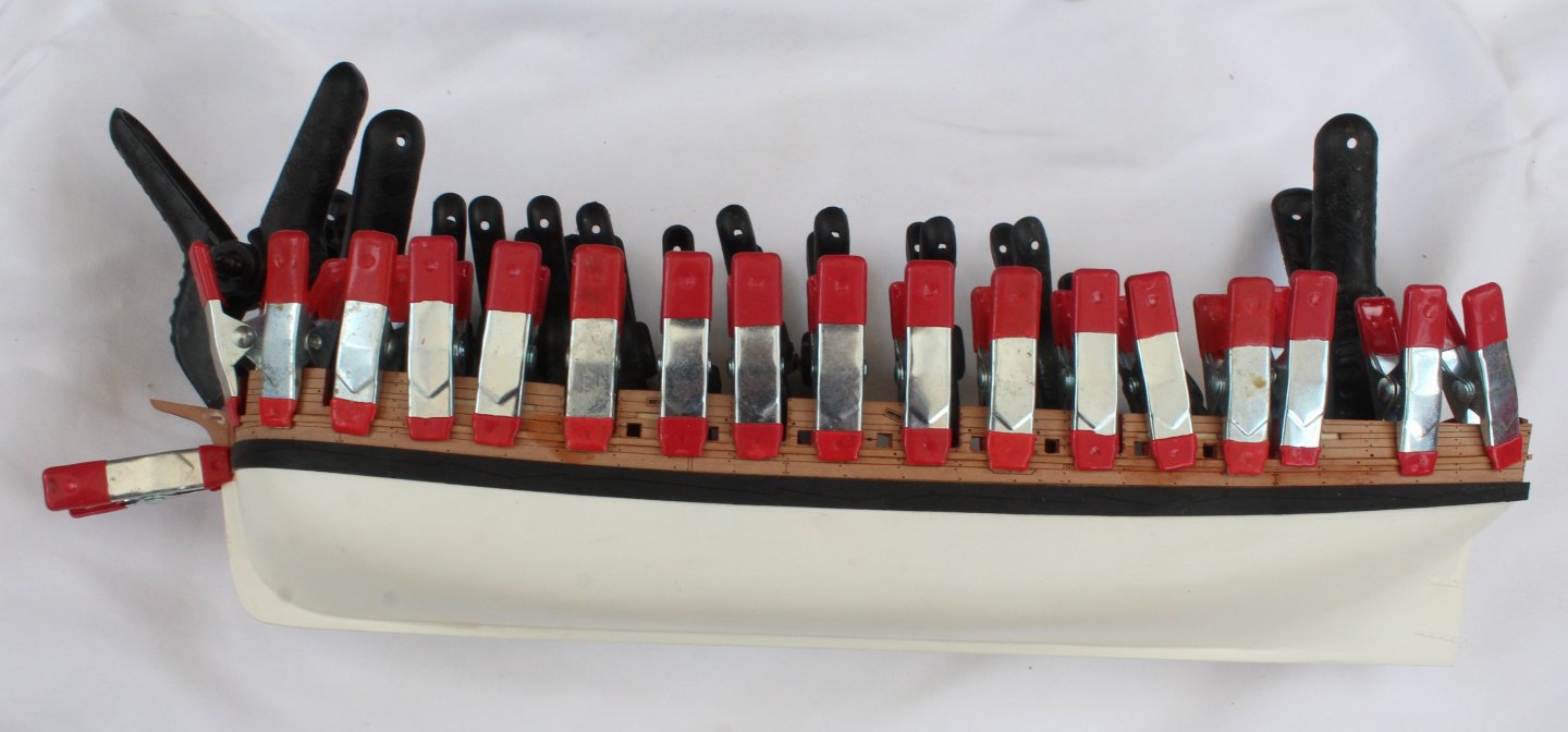
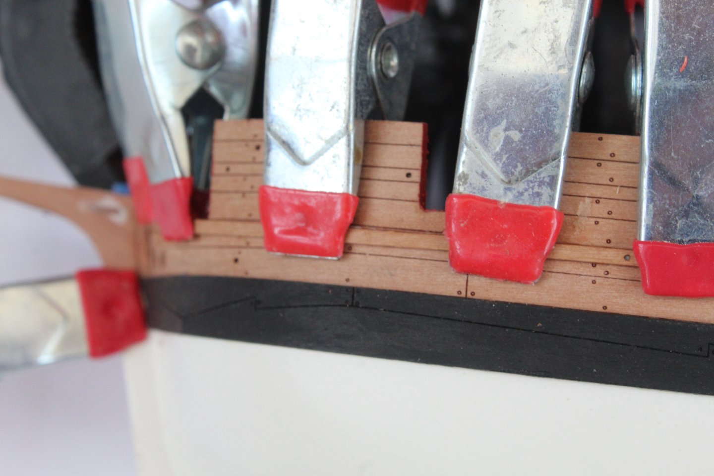
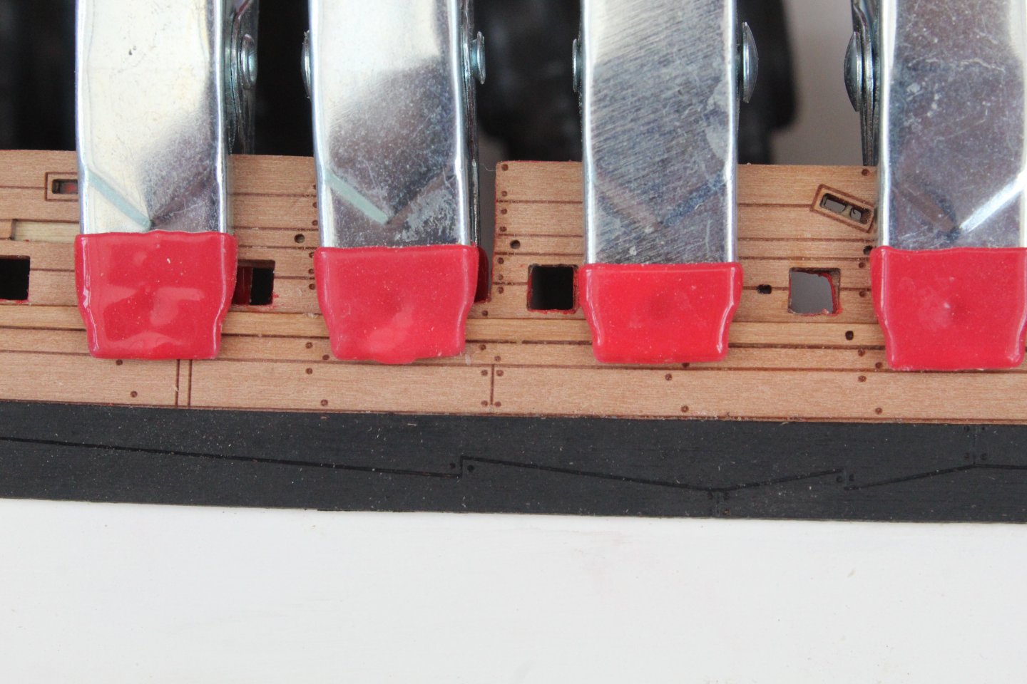
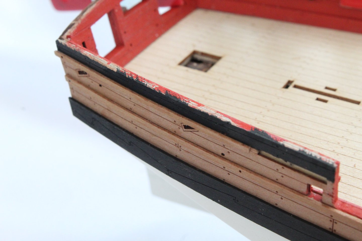
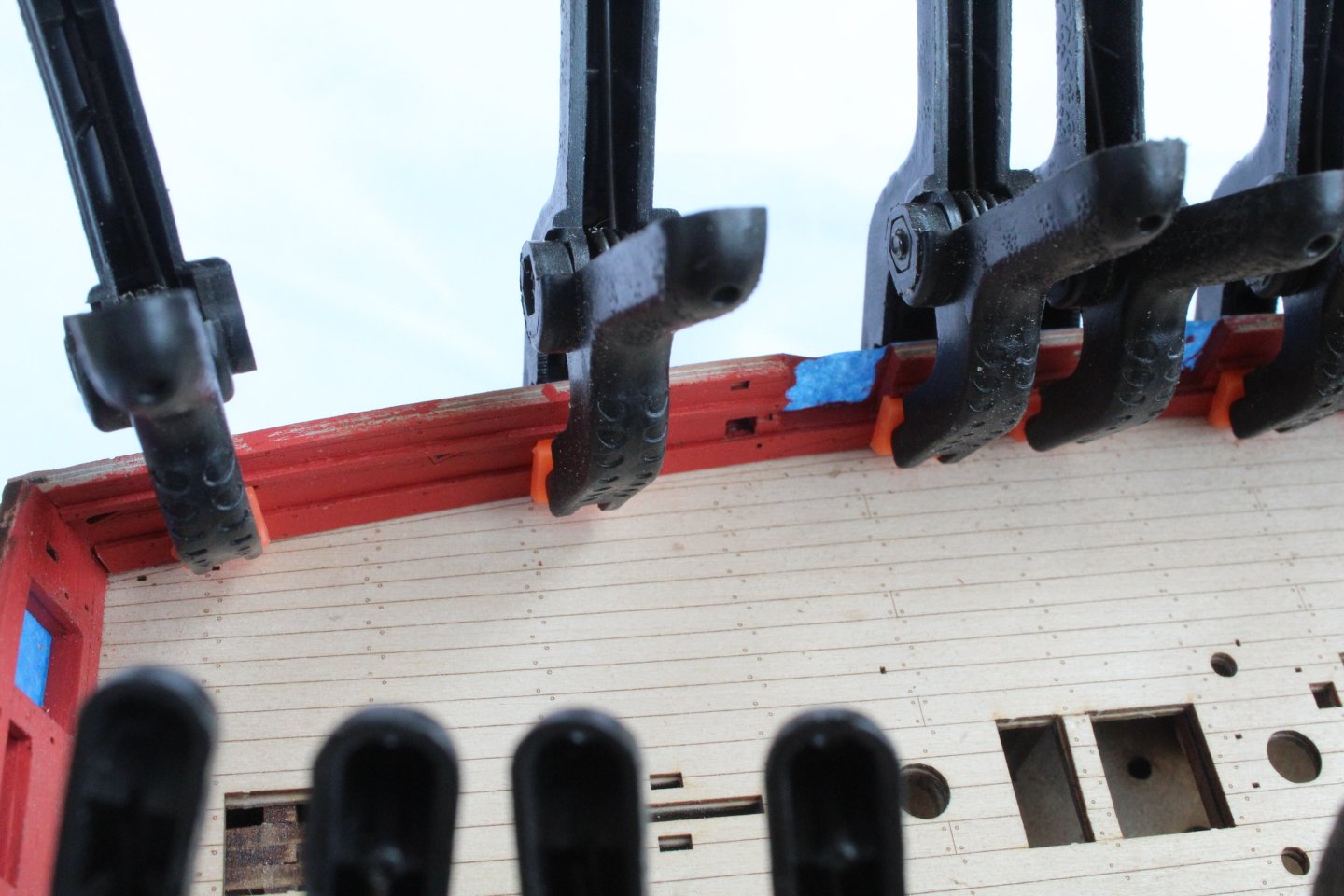
Build Log Index Date: 22/08/2024 Time worked today: 4 hours. Total time spent on build: 46 hours. Wales and External Rails As indicated in my last post the soaked wale patterns had been clamped to the hull. Once they were released a coat of varnish was brushed on followed by two coats of black paint. Before fitting the wales I did add some tape to protect the bulwark patterns from any excess glue. After applying the wales with wood glue they were added to the hull. I did use some clamps to hold them in place as the glue cured. The next job was to fit the lower rail patterns. After the laser char was removed they were giving a coat of wood glue and then clamped to the hull. After adding some tape to the bulwarks a coat of varnish was brushed on to the upper section followed by two coats of black paint. The final task was to add the upper rails.


-
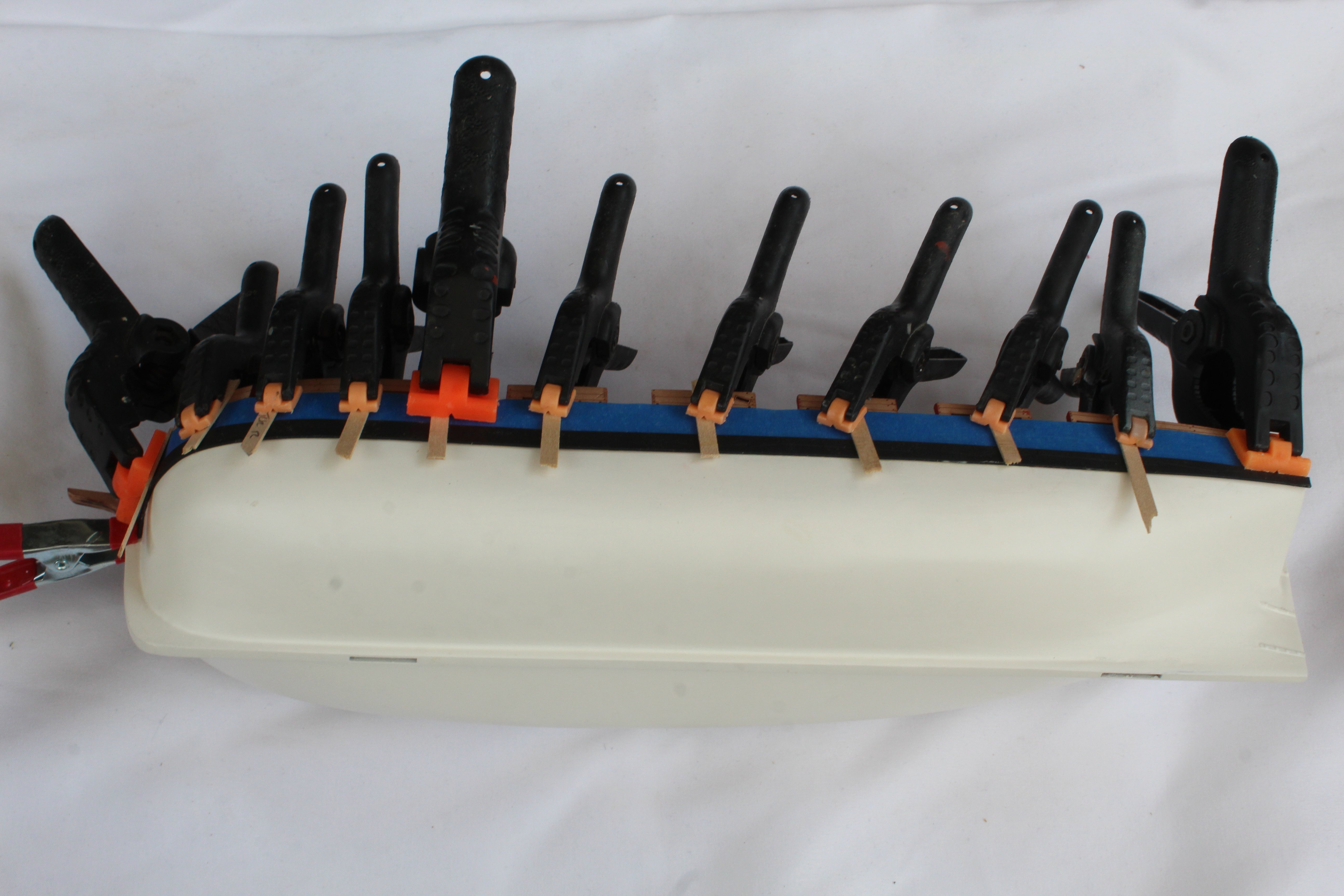
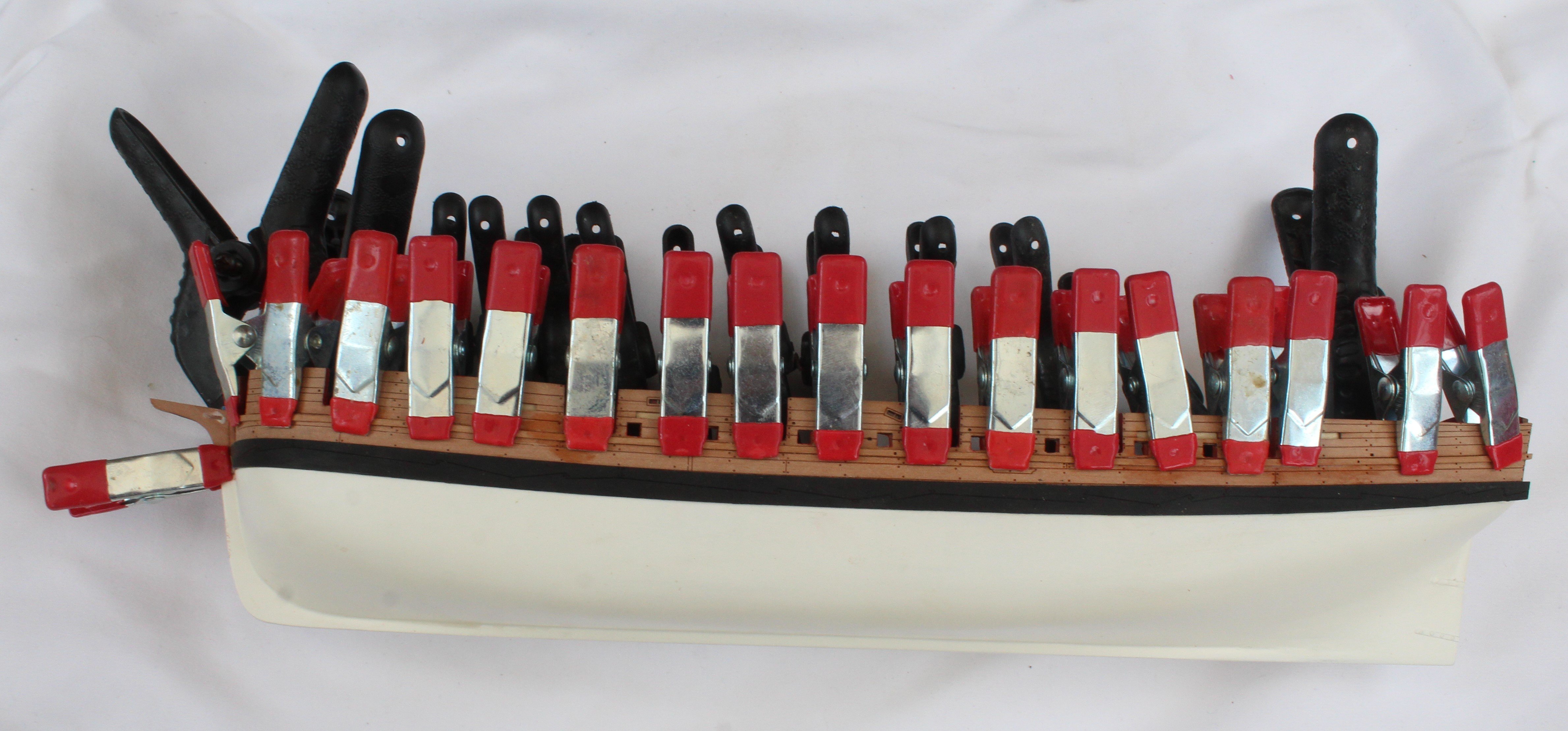
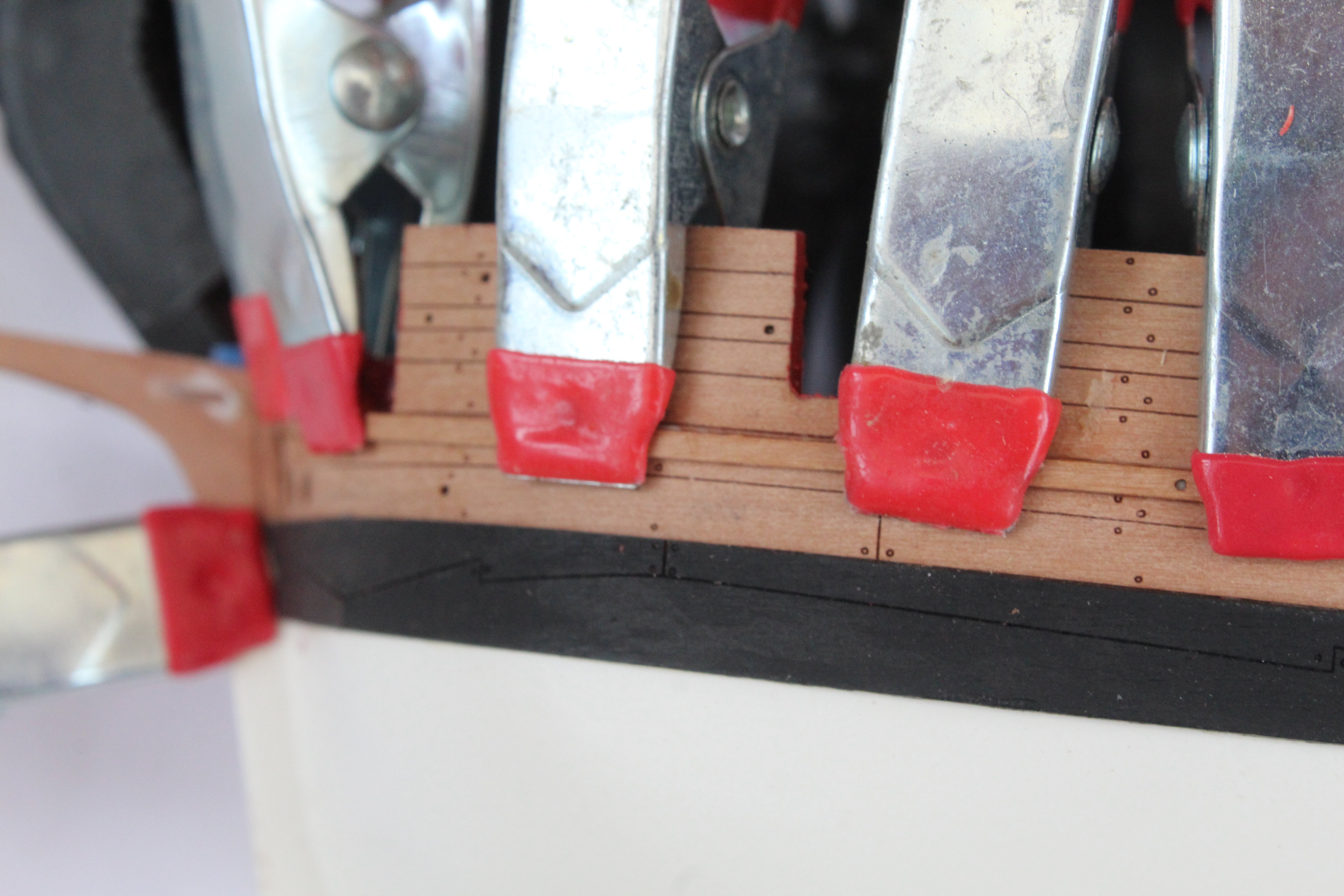
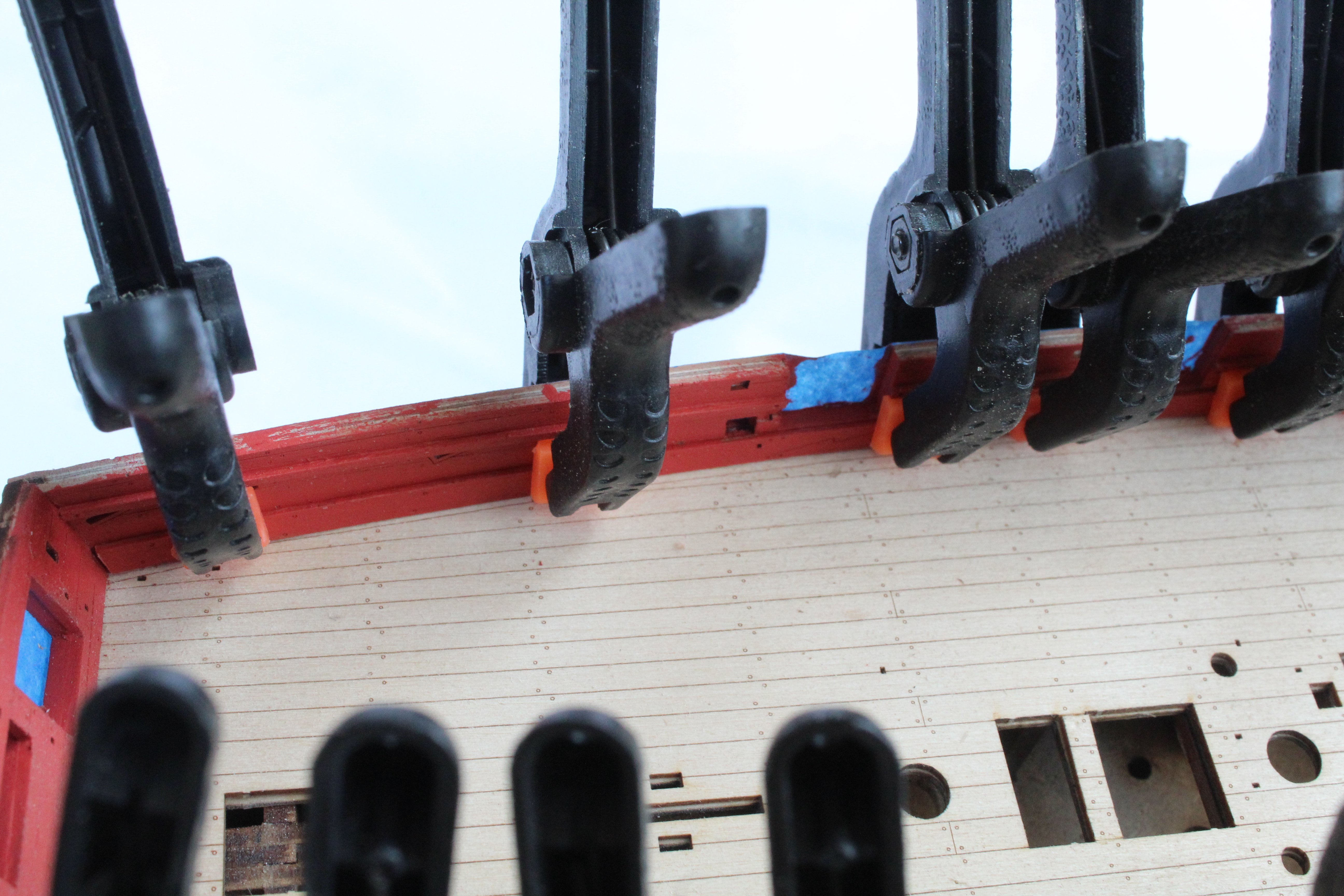
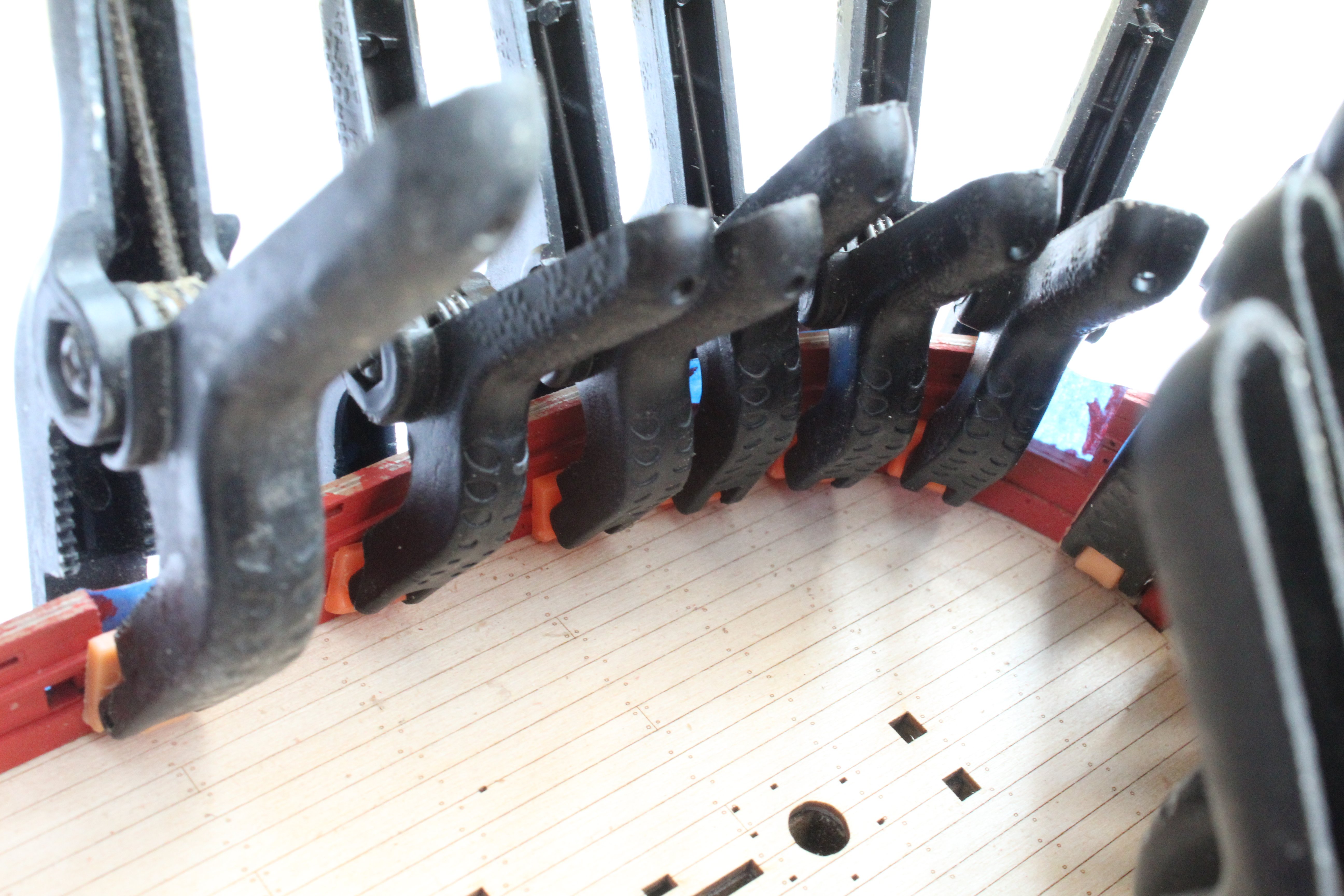
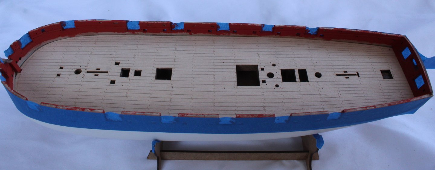
Build Log Index Date: 20/08/2024 Time worked today: 3 hours. Total time spent on build: 42 hours. Spirketting Before fitting the spirketting patterns a fine coat of vanish was brushed on the inner bulwarks which were then brush painted with two coats of flat red. I did tape the outer bulwarks to try to prevent unwanted paint leakage. I then checked the carronade eyebolts would fit in various bulwark holes. Where necessary a micro drill was used to ensure the eyebolts would fit. After trimming the spirketting patterns, a fine coat of vanish was brushed on them and then two coats of flat red paint were then brush on. The spirketting patterns were then glued in place and held in place using plenty of clamps. Once the glue had cured the clamps were removed. The wale patterns have been soaked in warm water and they are currently clamped to the hull and will be left to fully dry out over night.


-
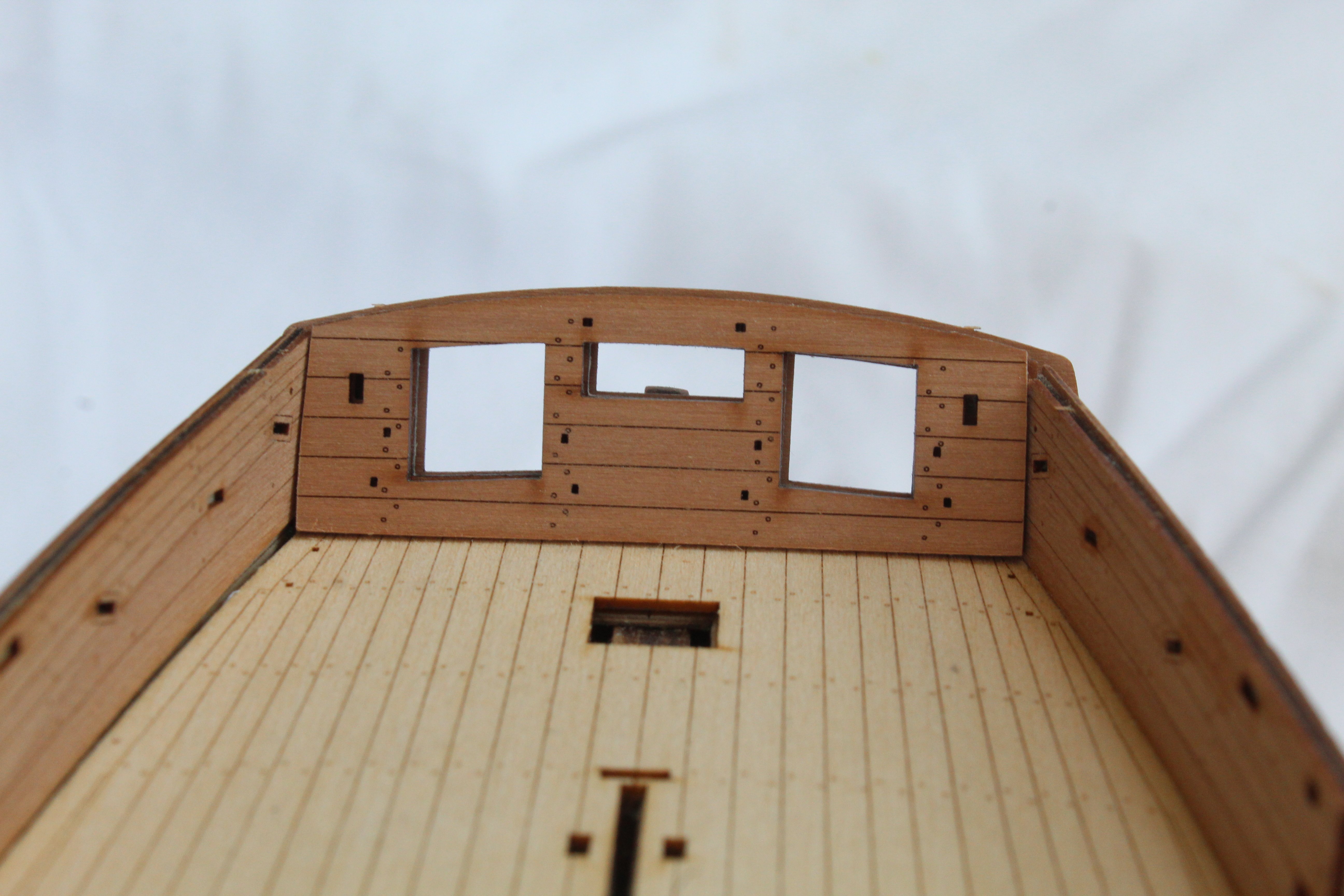
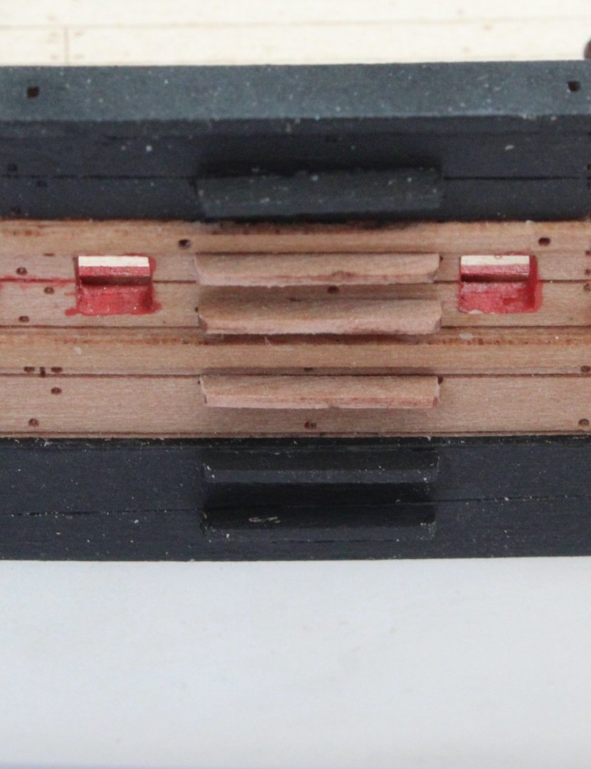
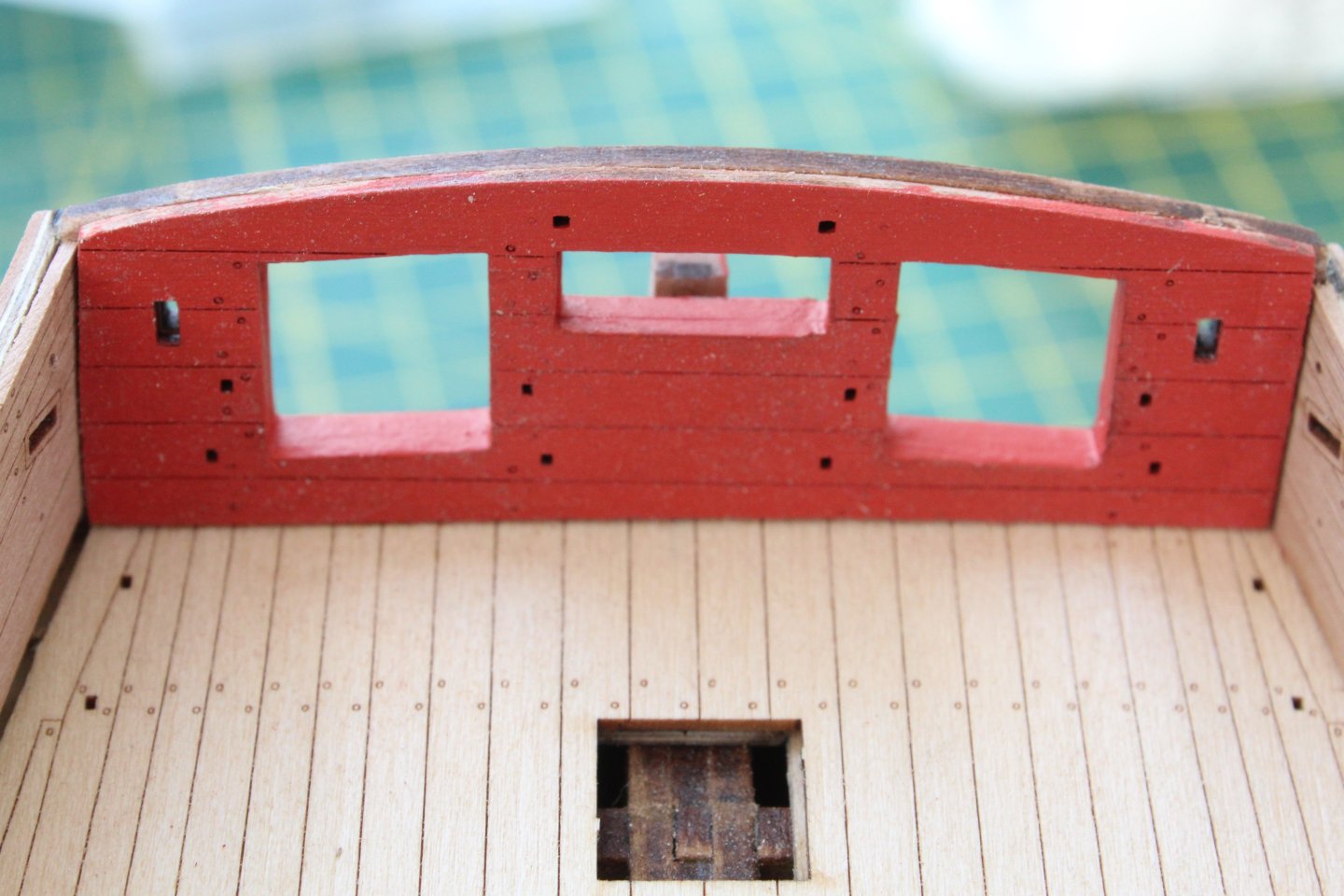
Build Log Index Date: 18/08/2024 Time worked today: 1 hour. Total time spent on build: 39 hours. Fitting Inner Stern Transom Pattern As indicated in a previous post the inner stern transom pattern had been trimmed during the dry fitting process. Today a light coat of varnish was brushed on the pattern. Once that had dried 2 coats of flat red paint were brushed on. Before gluing the pattern in place, a trial fit of the inner transom pattern cleats was done. This is much easier to check before the pattern is fixed in place. The pattern was then glued in place. I did apply of red paint to the openings once the glue had cured. Preparing Inner Bulwark Rails The various inner bulwark rail patterns were removed from the 0.8mm sheet and the laser char was carefully removed from the edges. There is still a bit of work required to fit these rails as they may need trimmed to ensure they are aligned with the edges of the various gun port openings. It will be slow and steady work to complete.
-
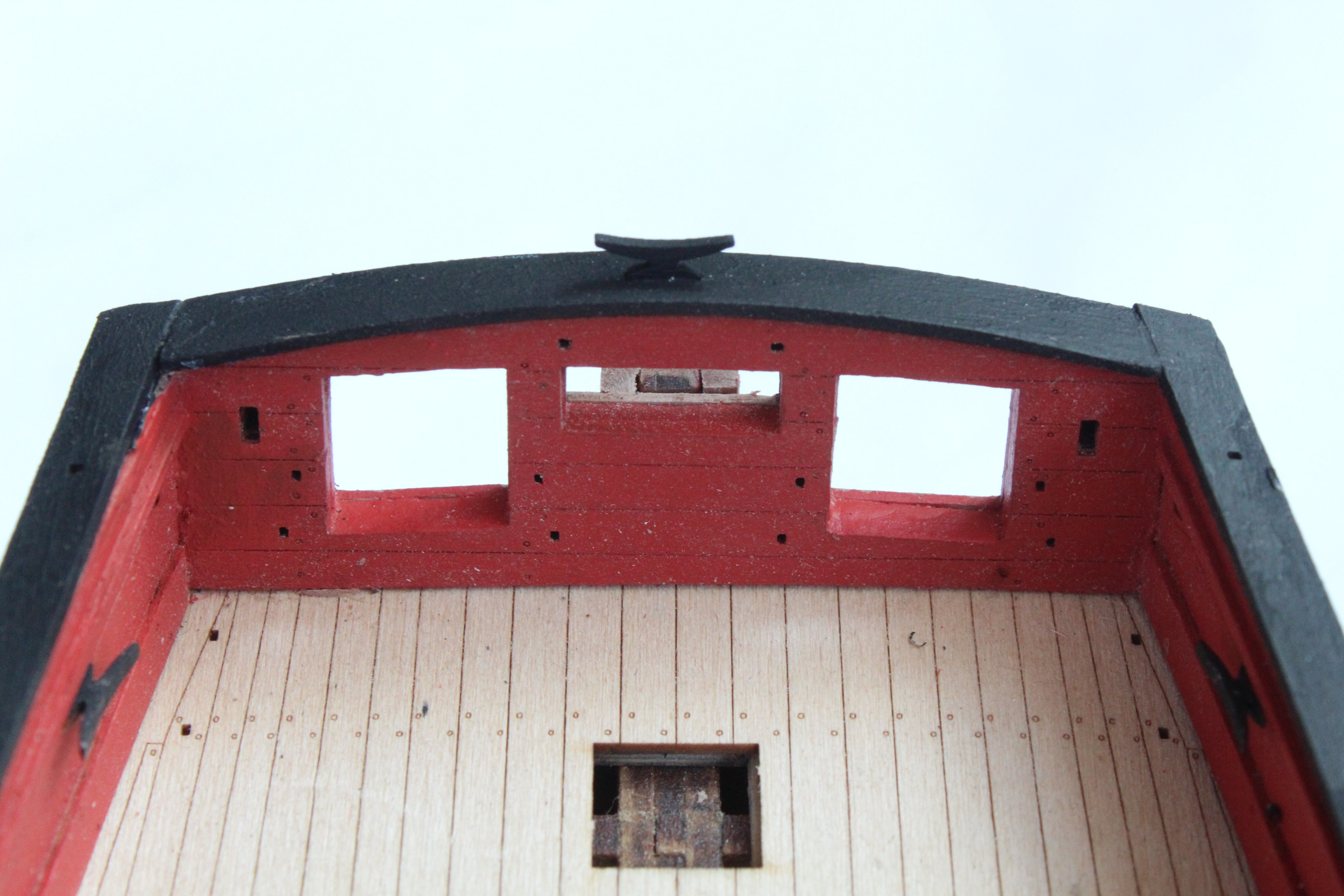
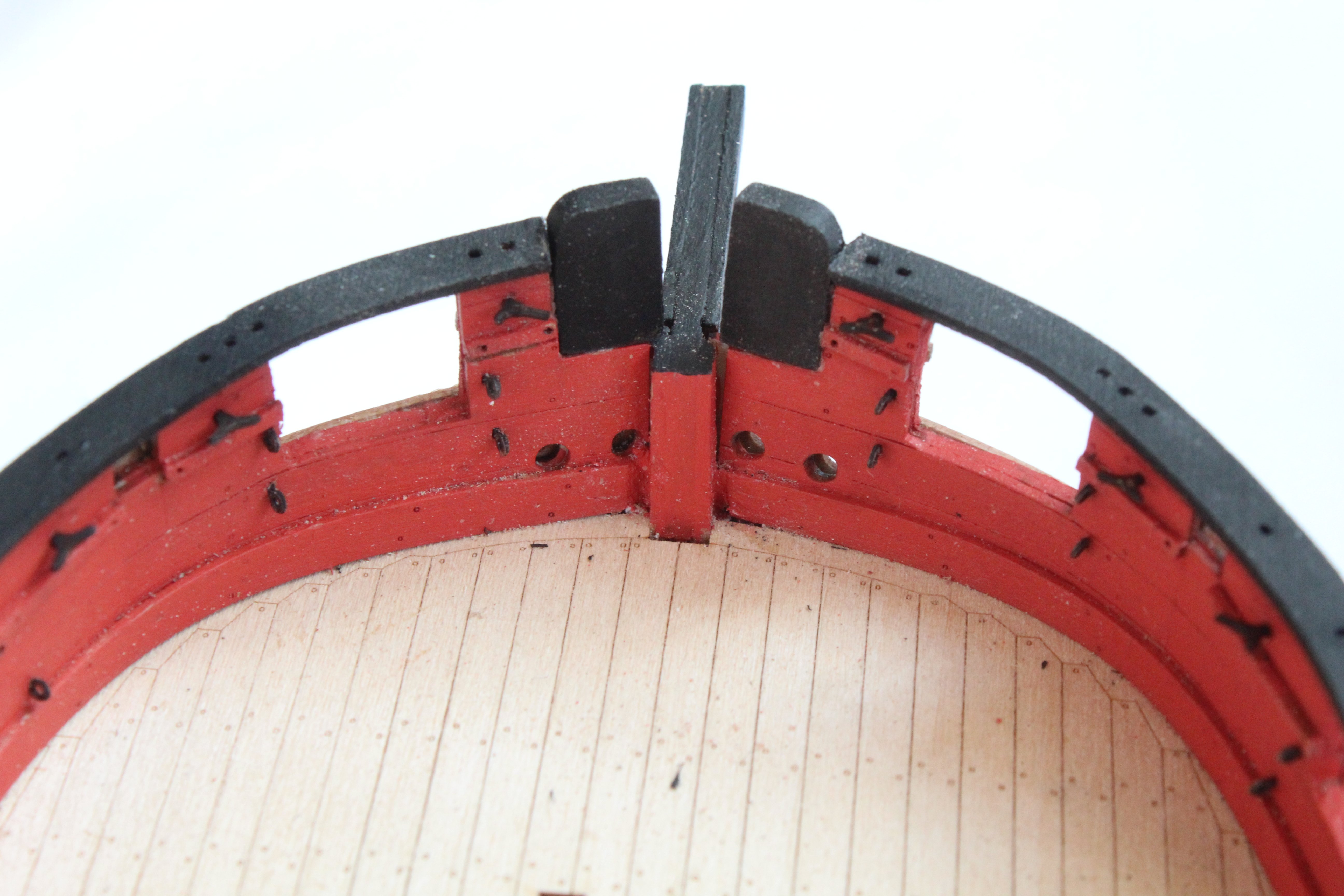
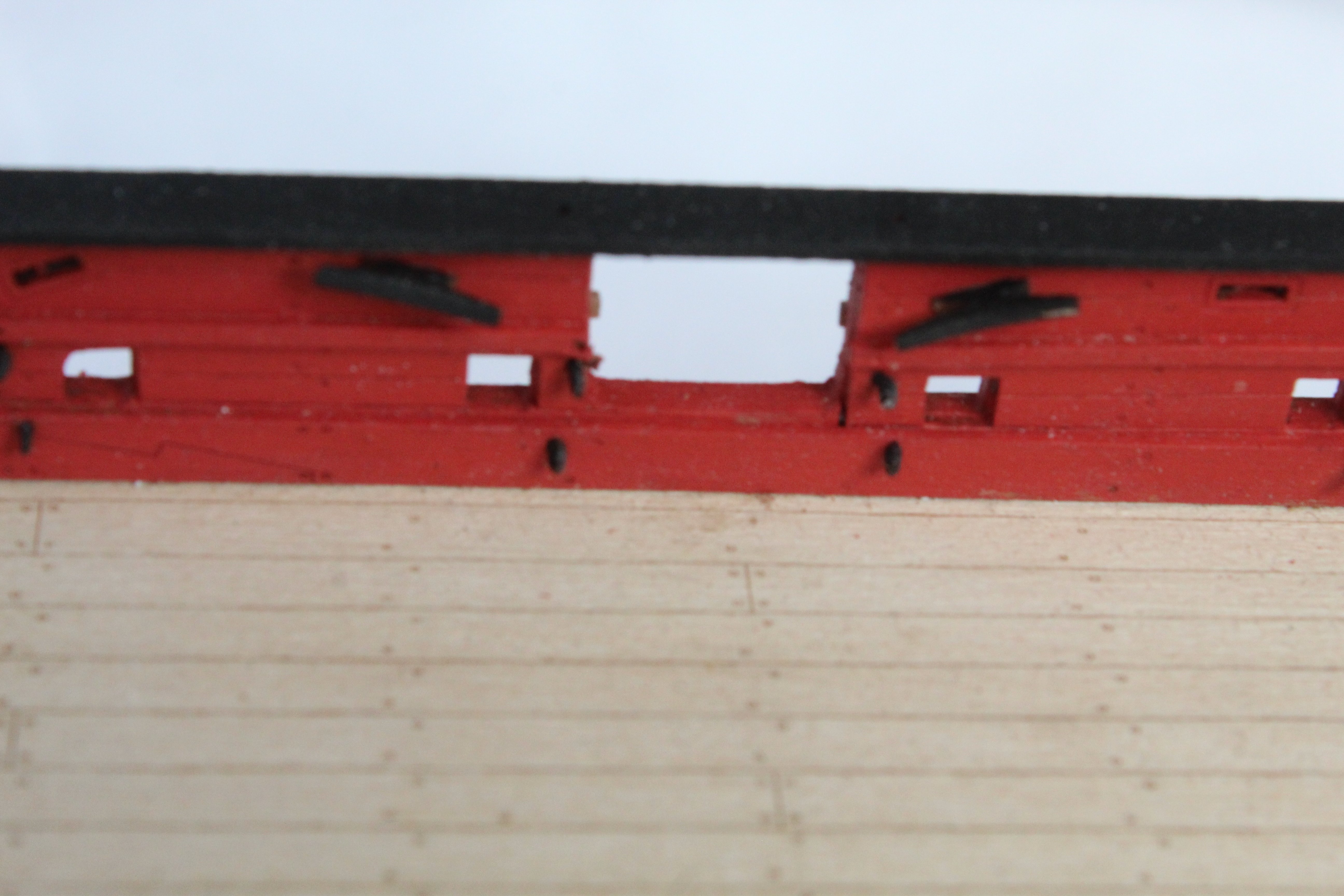
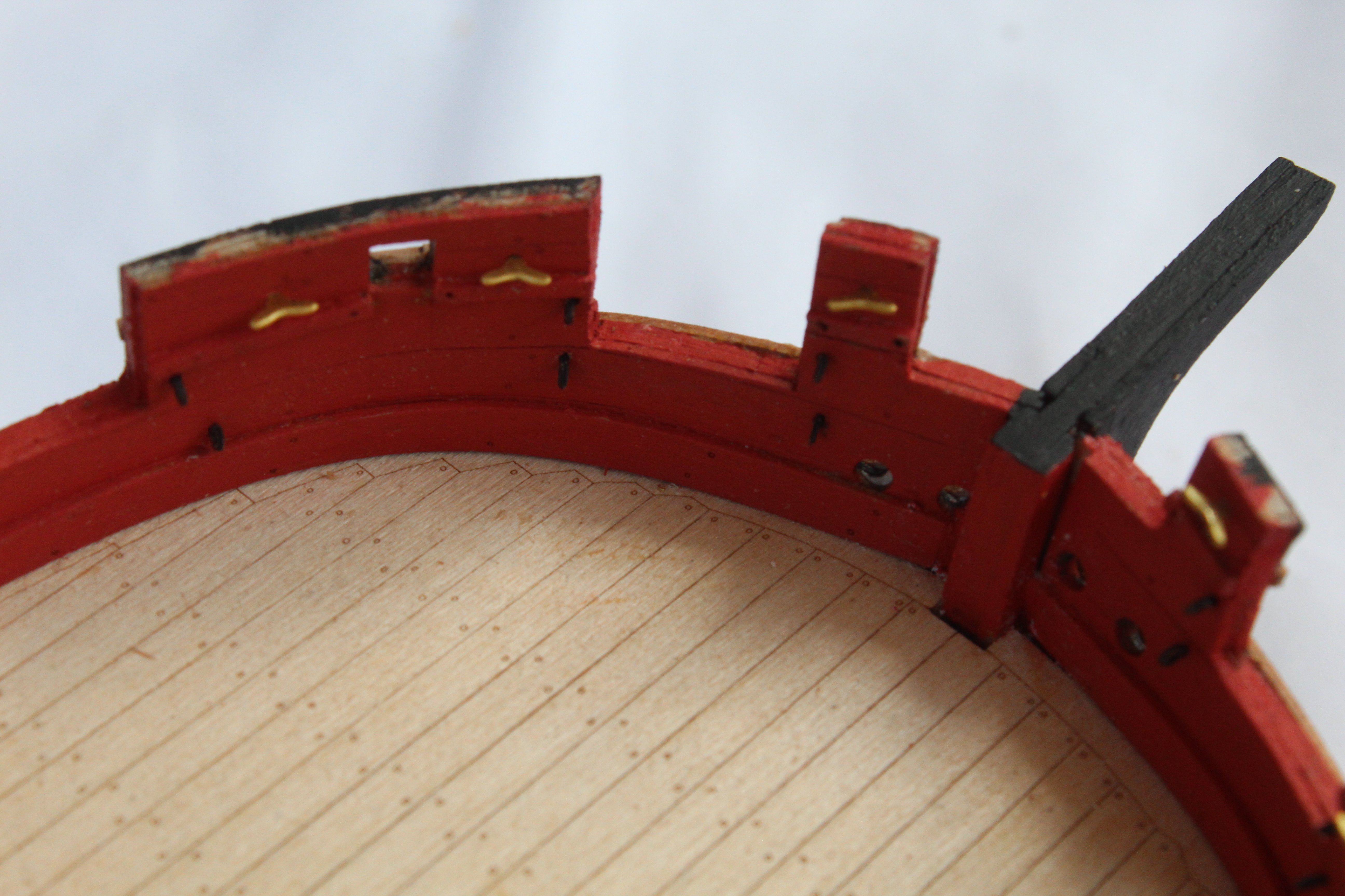
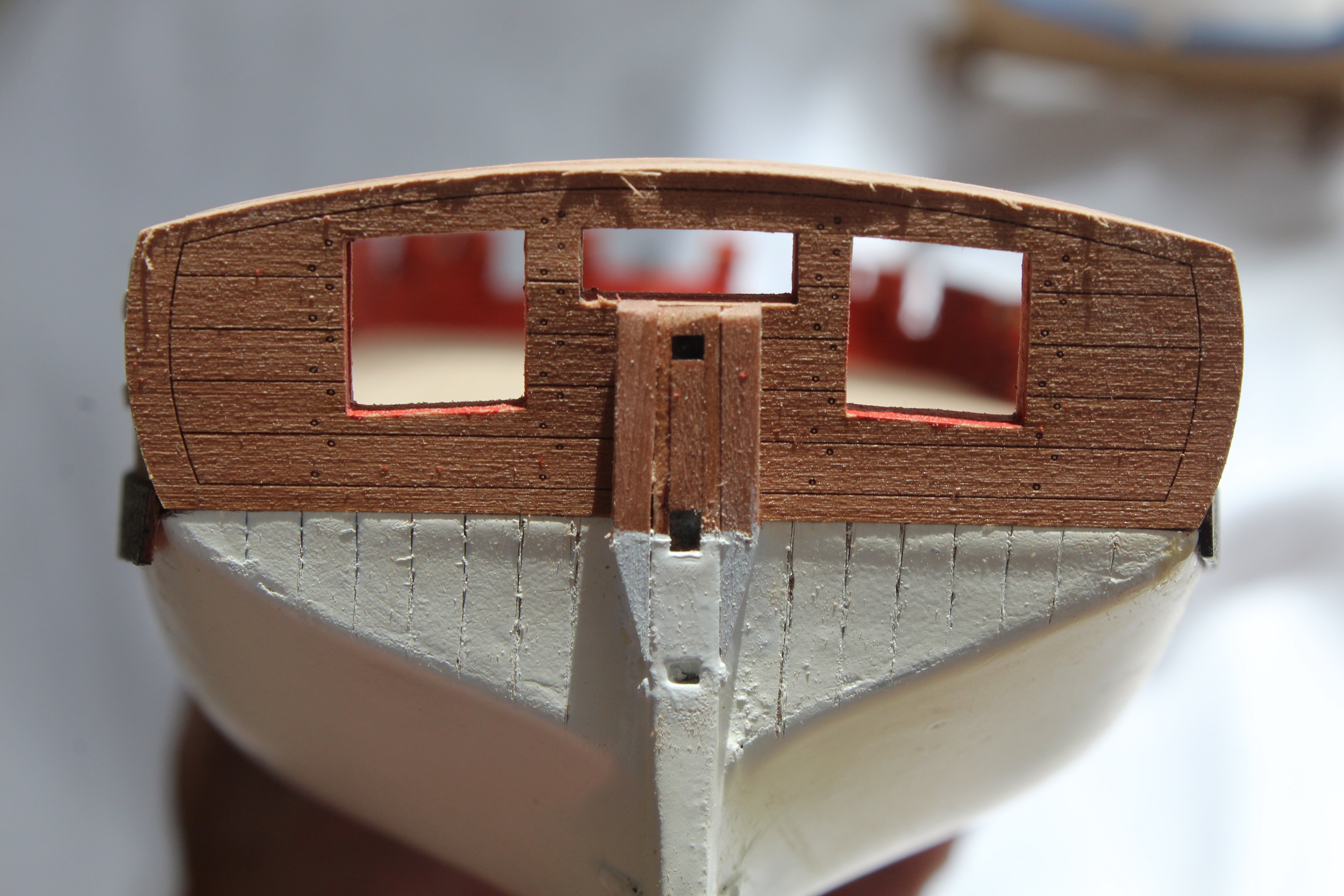
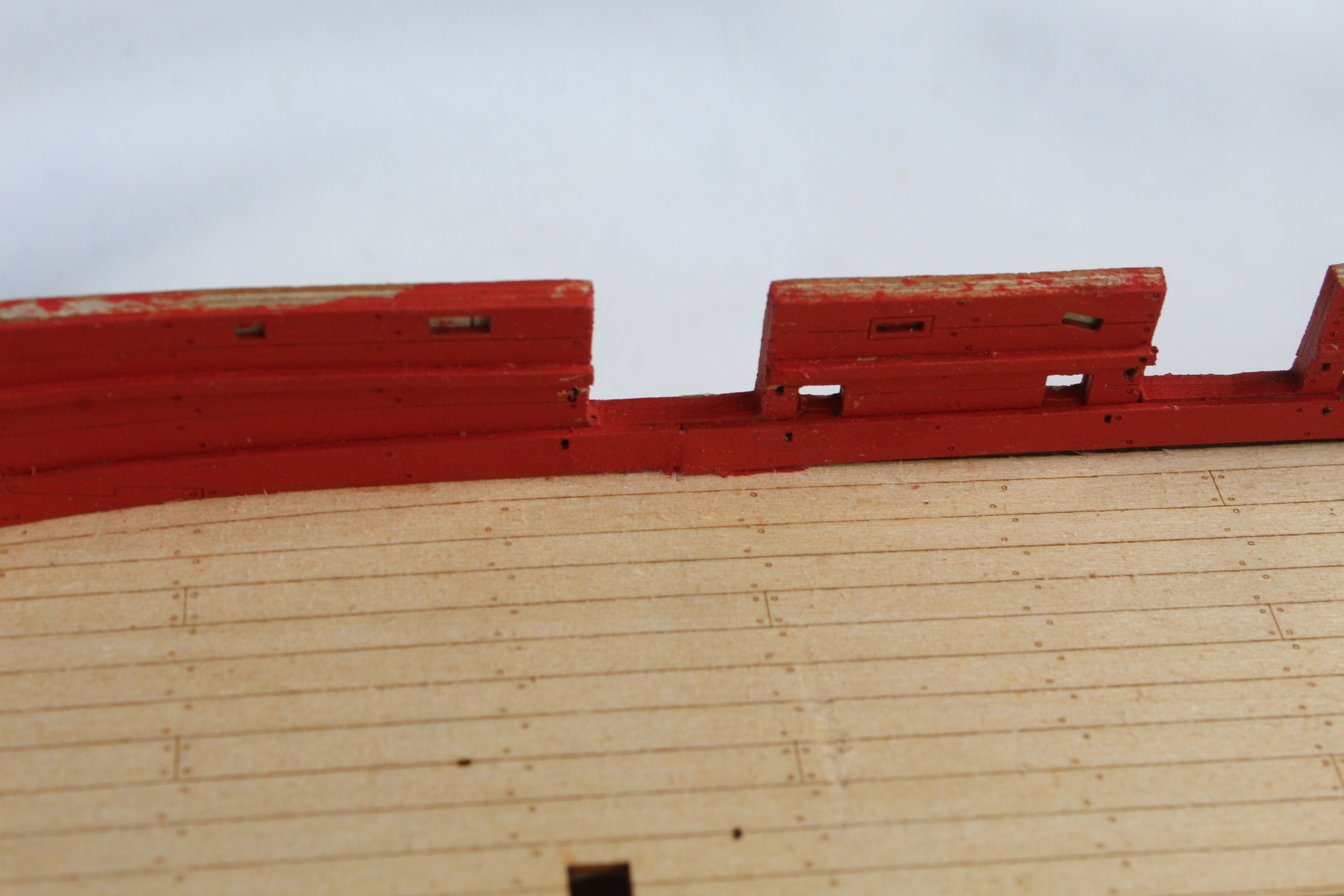
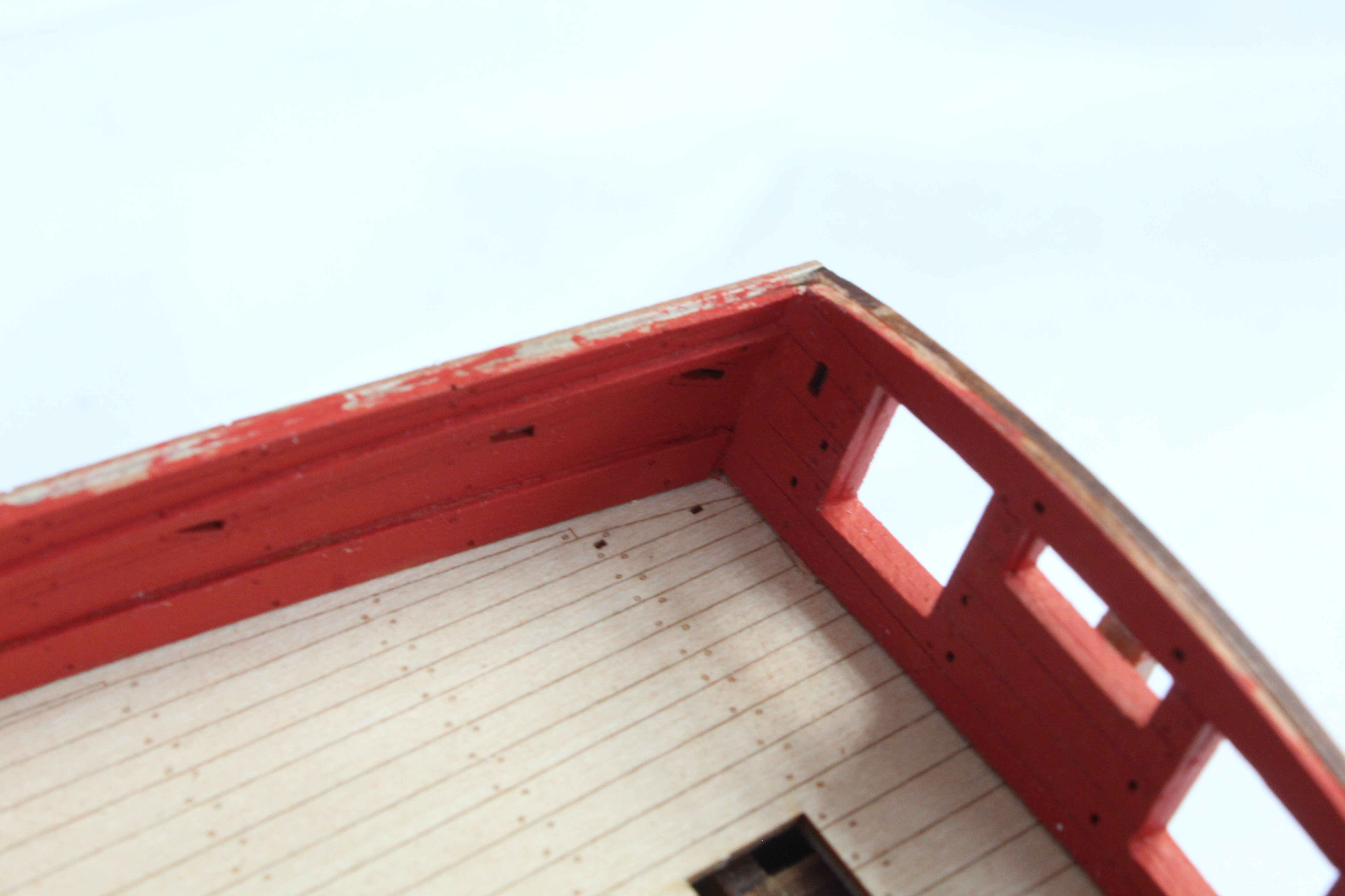
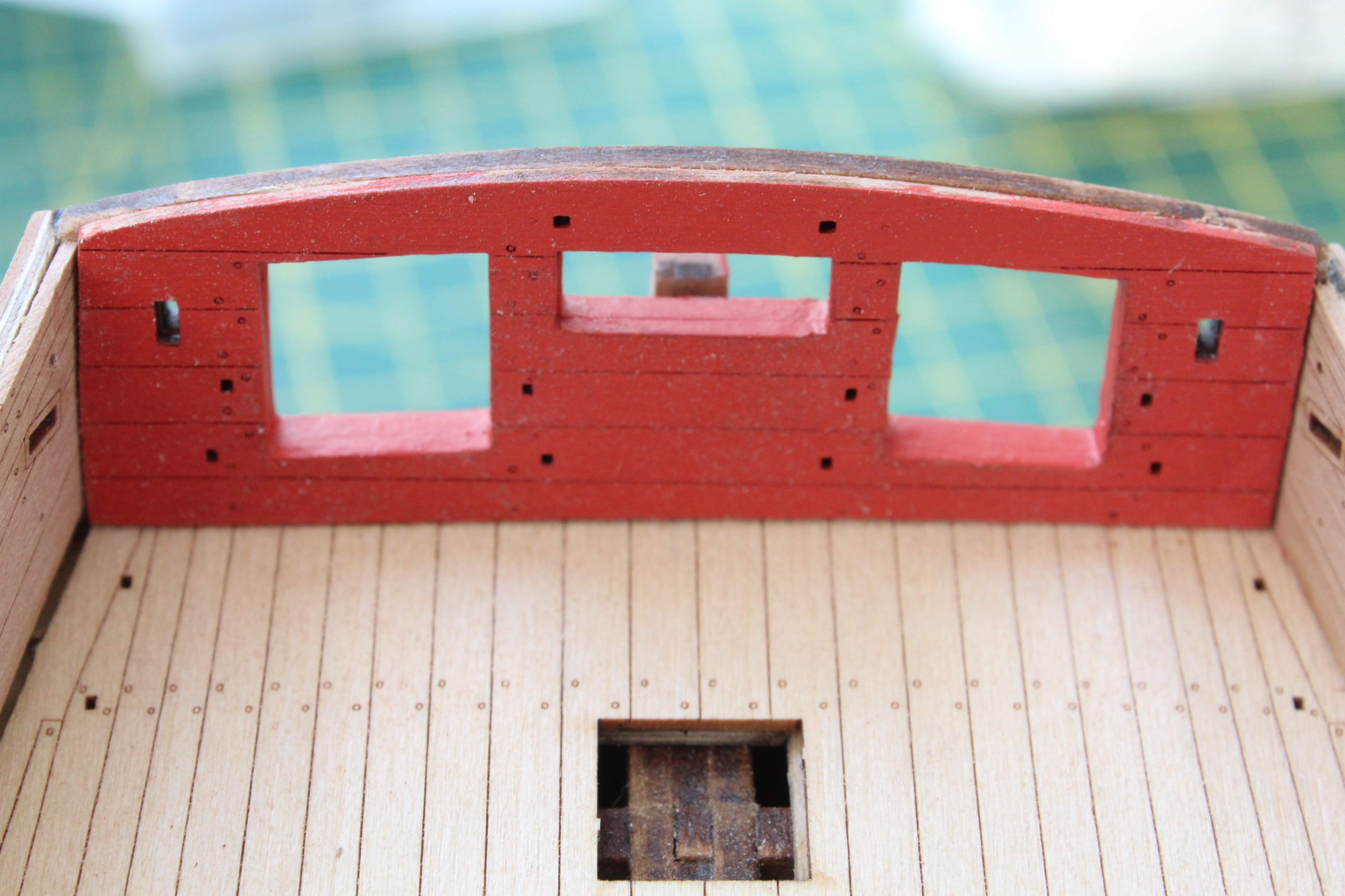
Build Log Index Date: 17/08/2024 Time worked today: 0.5 hours. Total time spent on build: 38 hours. Fitting Inner Bulwarks and Test Fit Deck Items The two bow inner bulwark patterns were soaked in hot water for a few minutes and then clamped in position. Once the parts had fully dried out they were glued in place along with the two aft inner bulwark patterns. Plenty of clamps were used to hold the patterns in place as the glue cured. Next was a dry fit of the inner transom pattern, which did require a little bit of sanding before it was aligned with the openings. The excess aft outer bulwark pattern material was trimmed and sanded smooth and the outer upper transom pattern was then test fitted, it was not quite in the right position in the photo below. It needed to be be moved slight to the right. Using a razor saw all the gun ports were opened. They will require filing and sanding before moving on to the next stage of fitting the inner rails. It was now a good time to test fit some of the deck items that I had previously constructed. There is still plenty of other work to complete before these deck items will be fitted.


-
Hello Andrew. They do look great.
-
Thanks Ronald
-
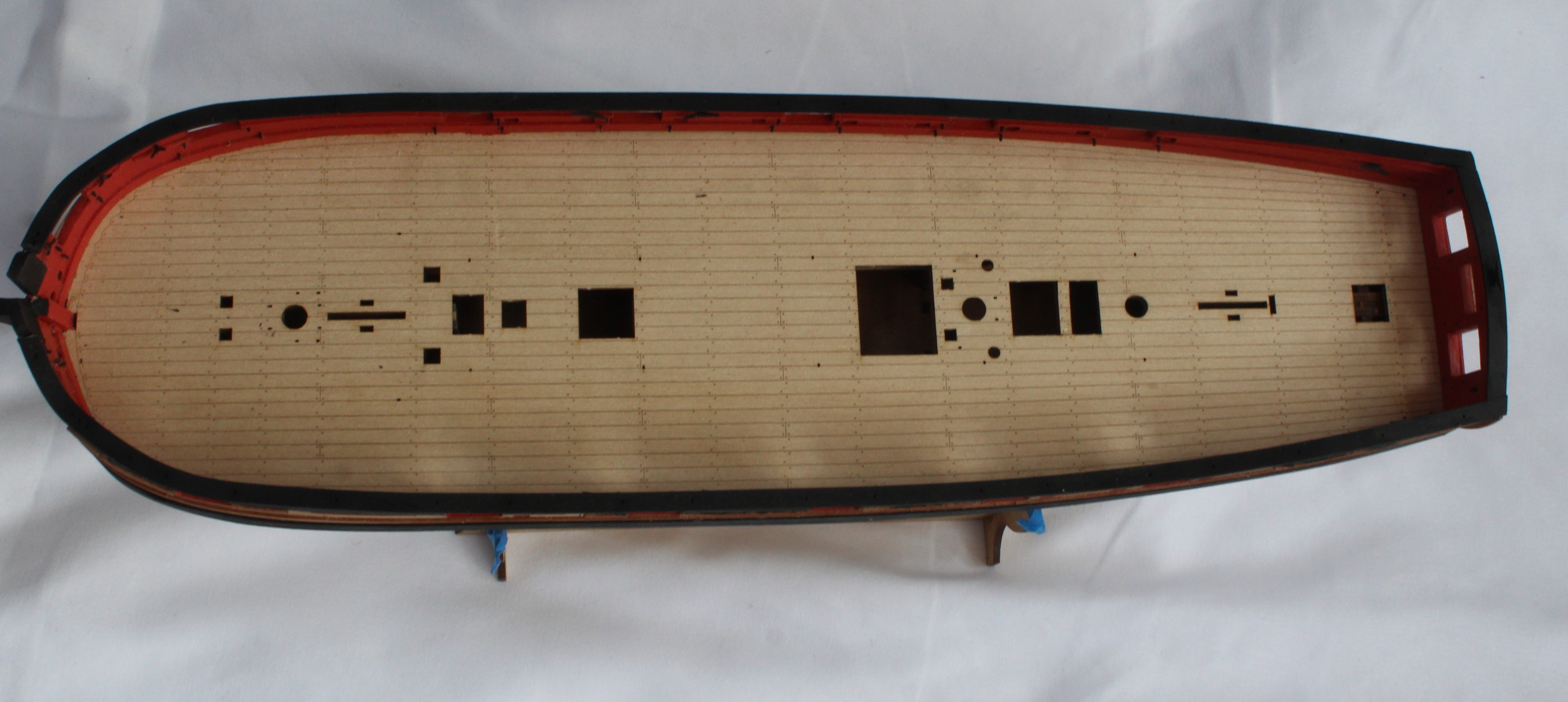
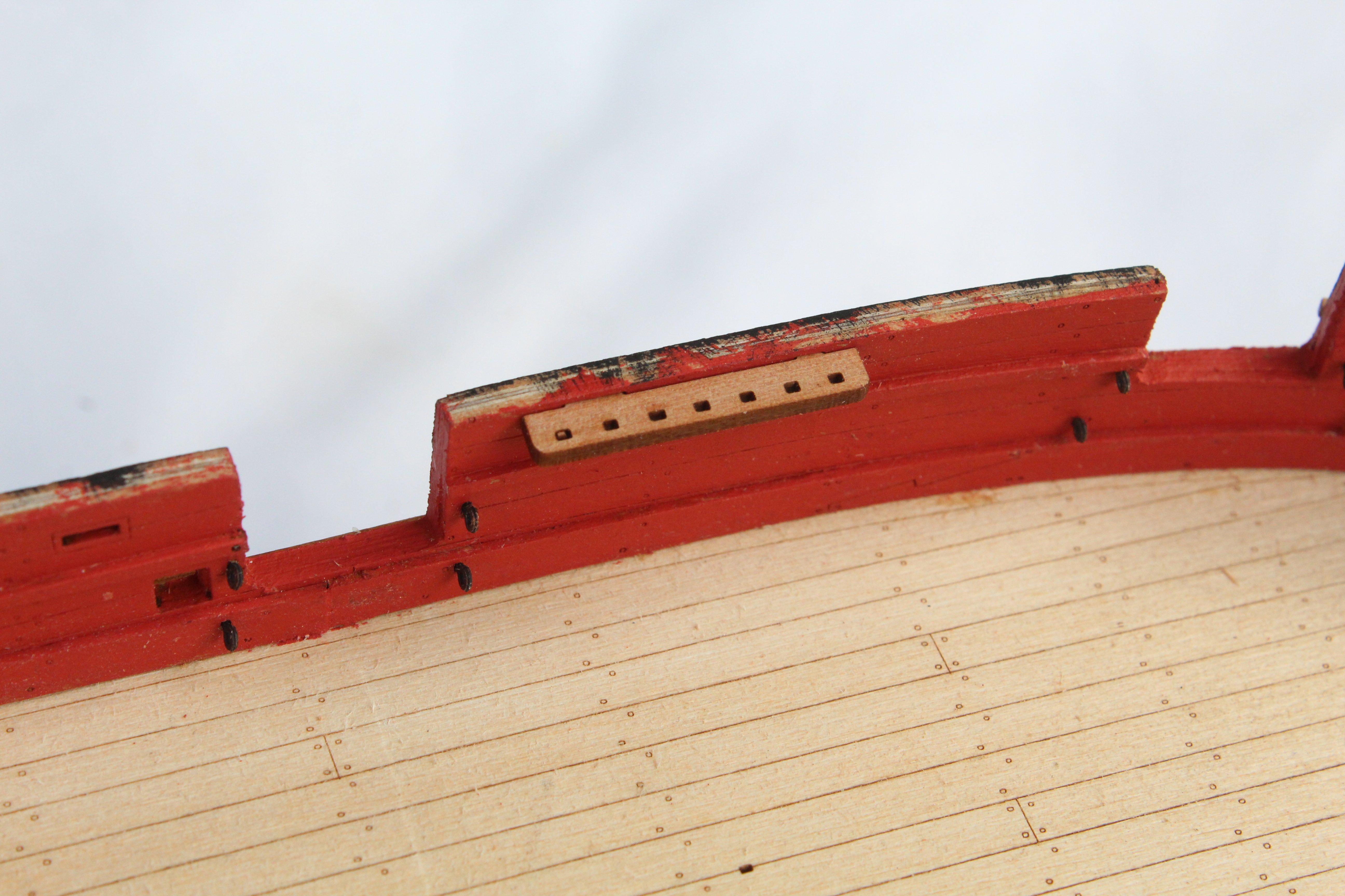
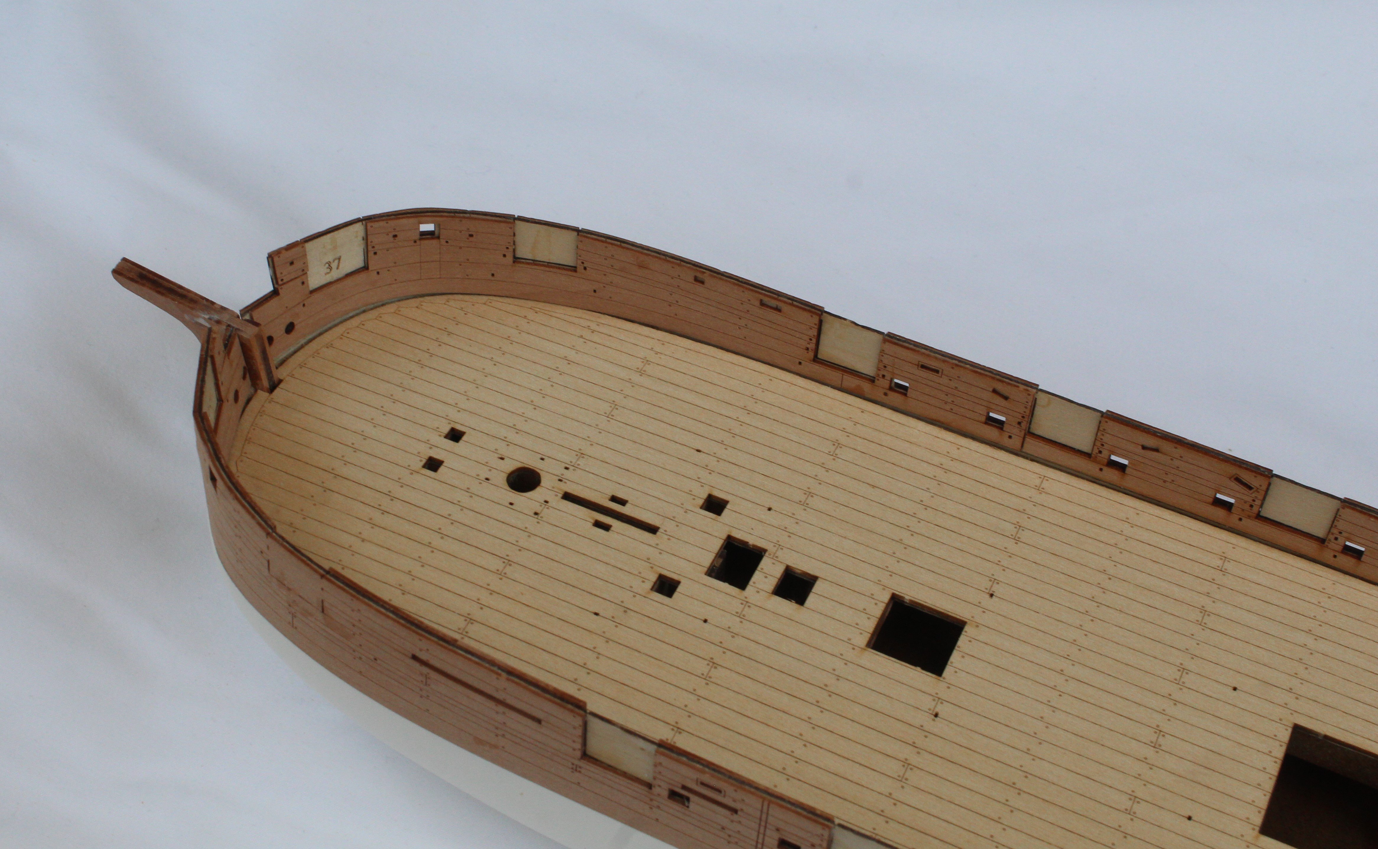
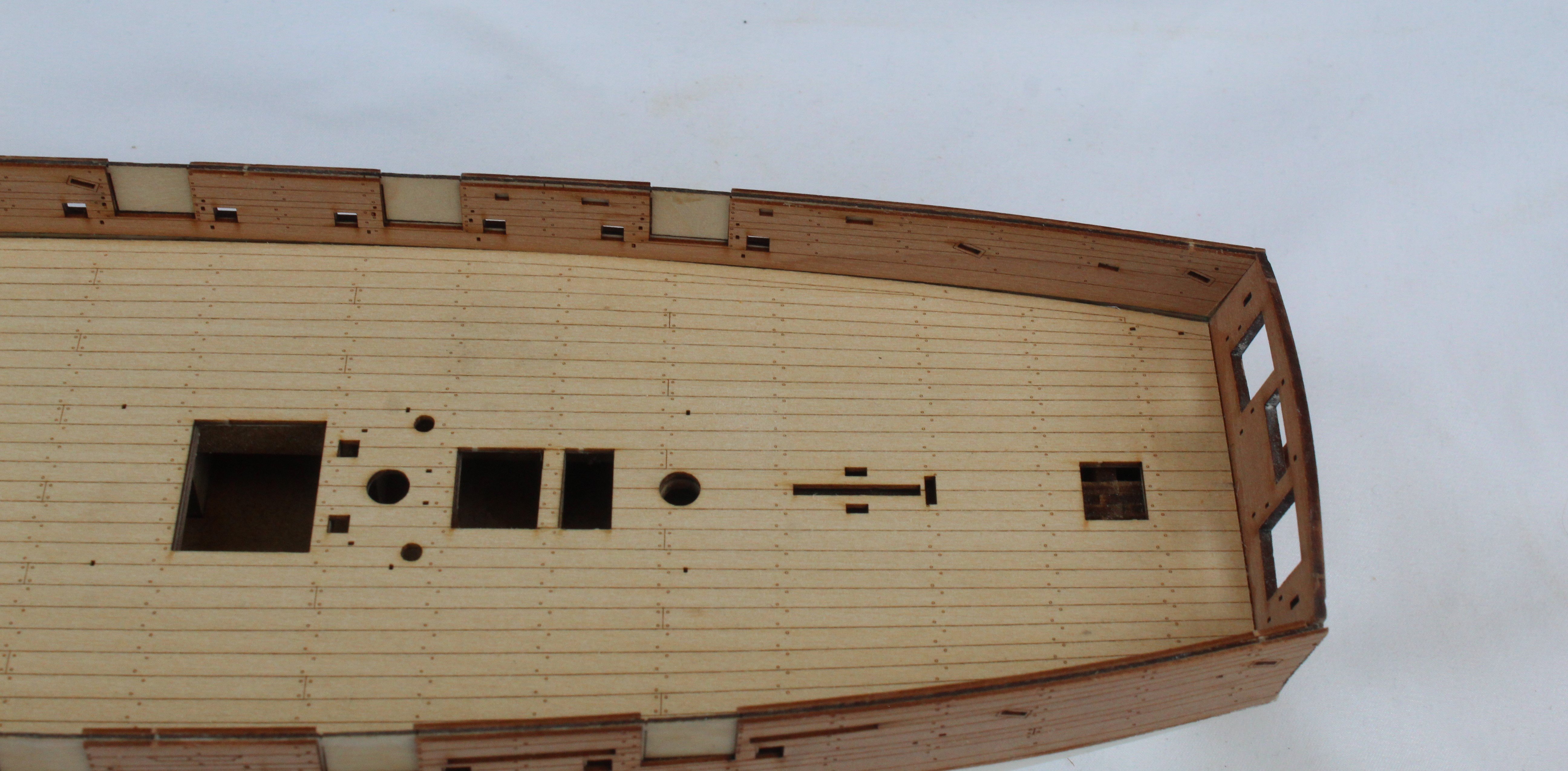
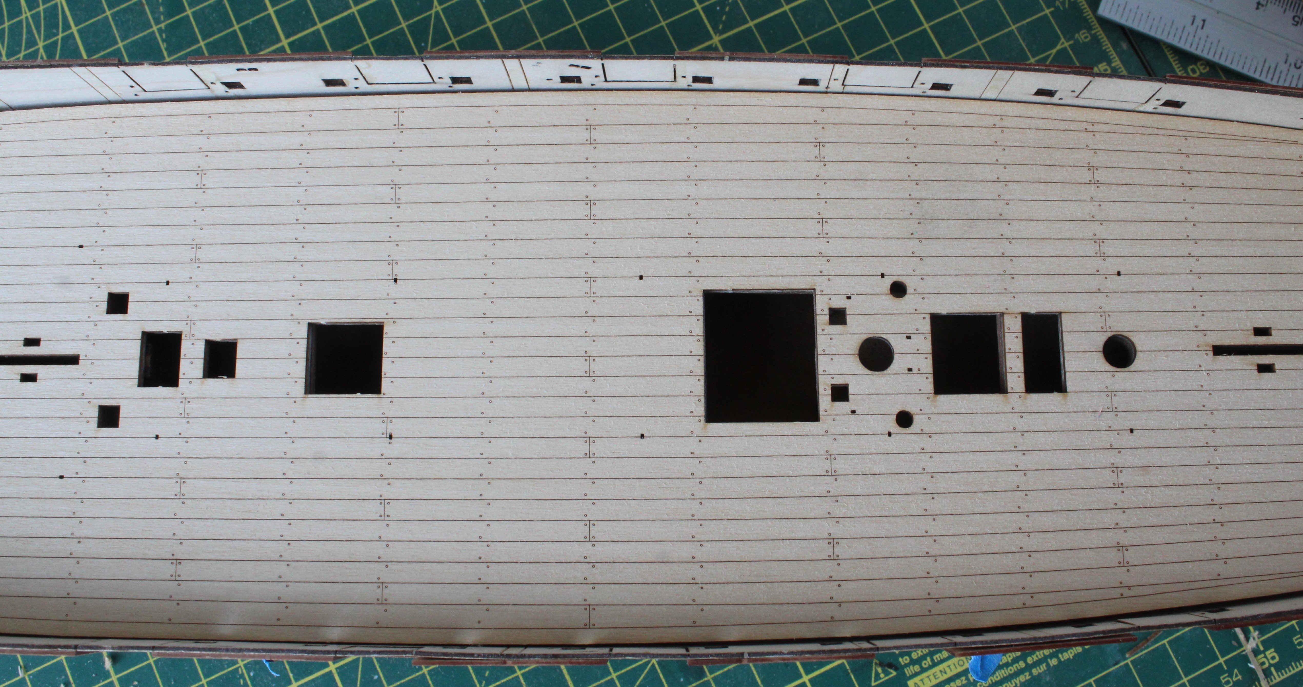
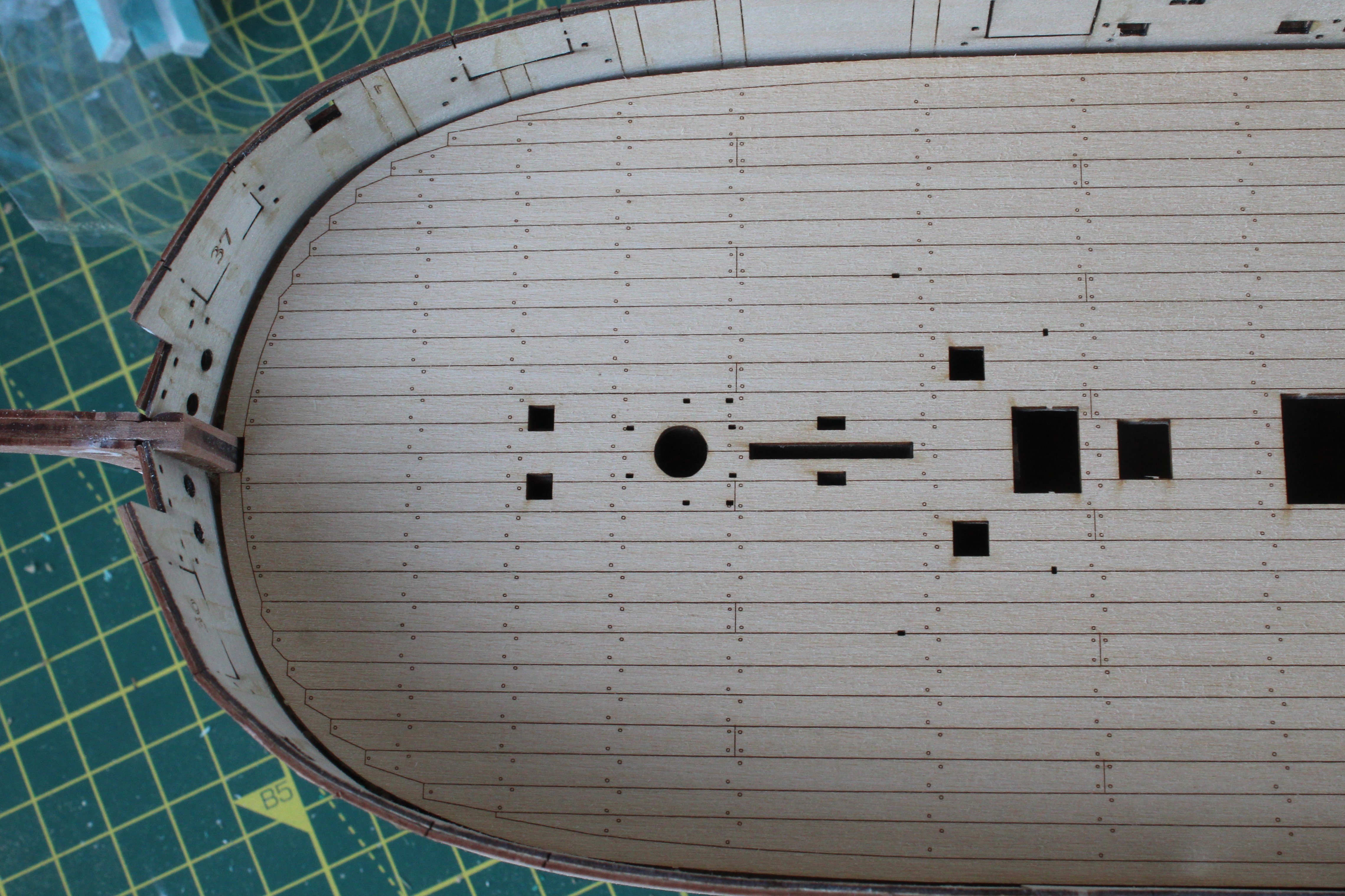
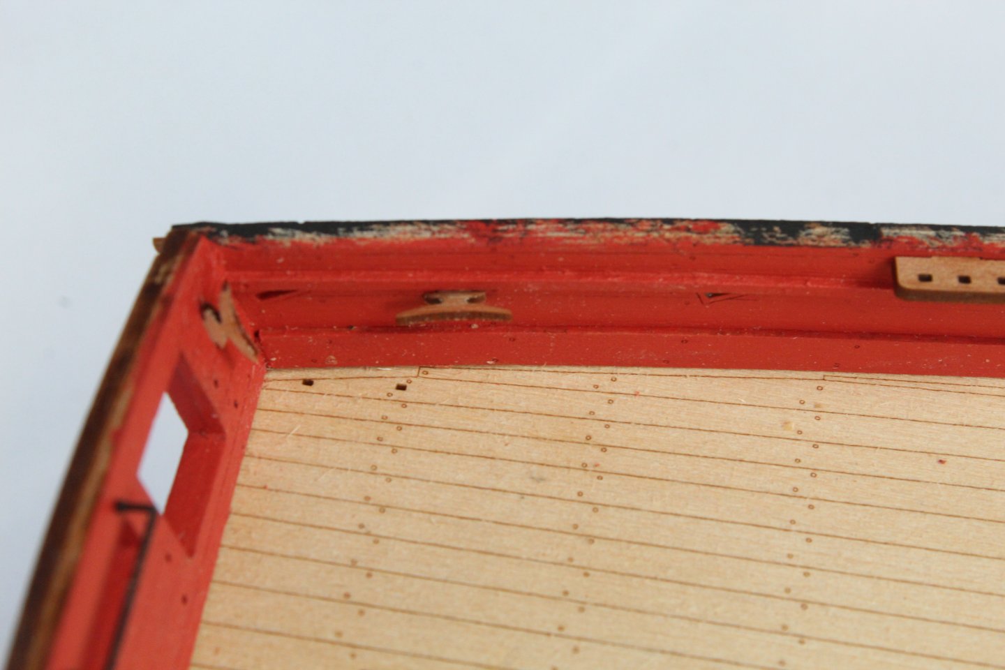
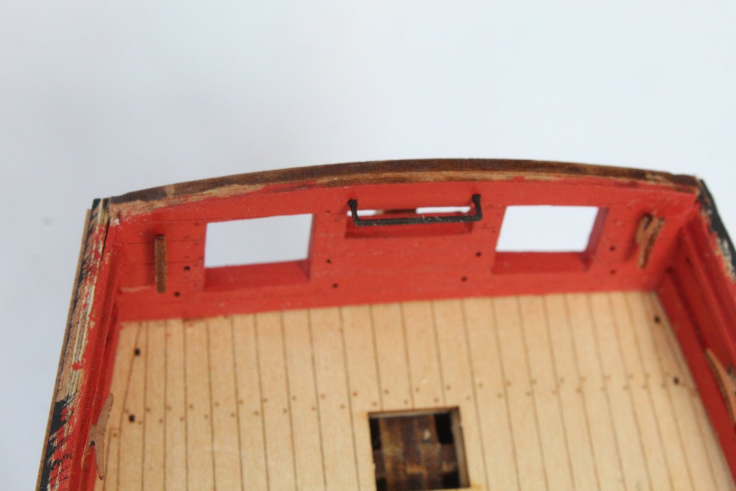
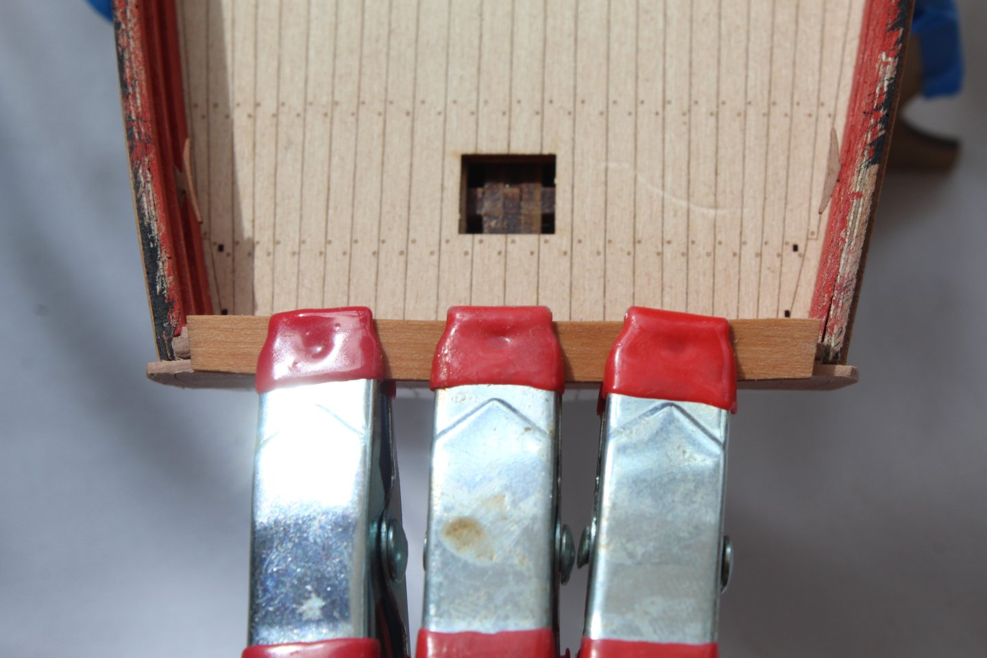
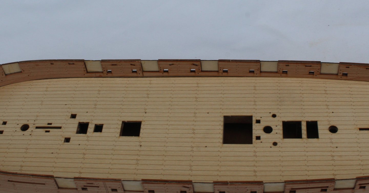
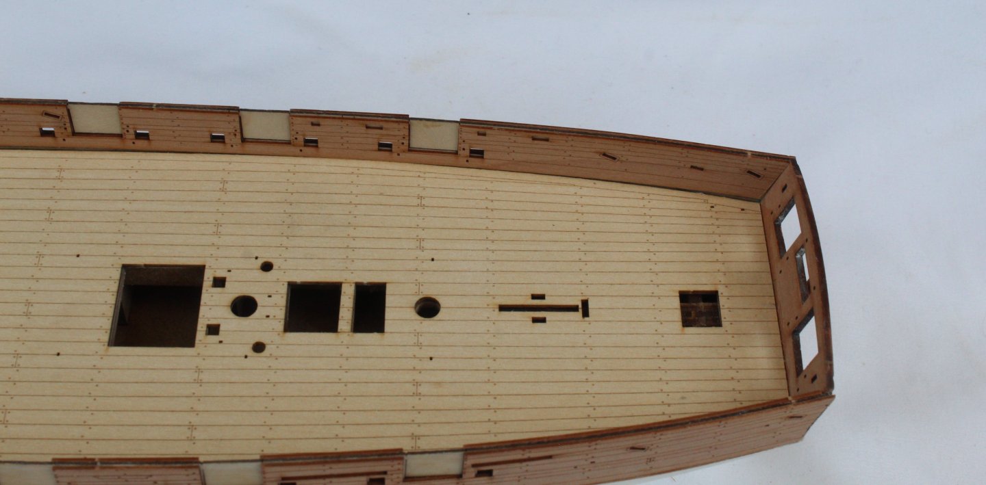
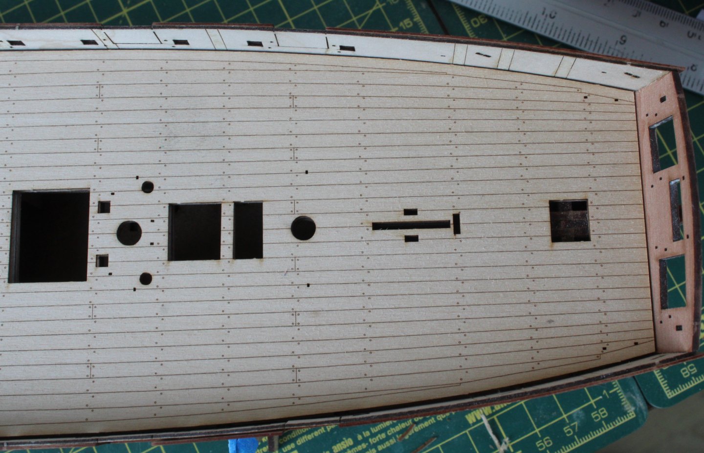
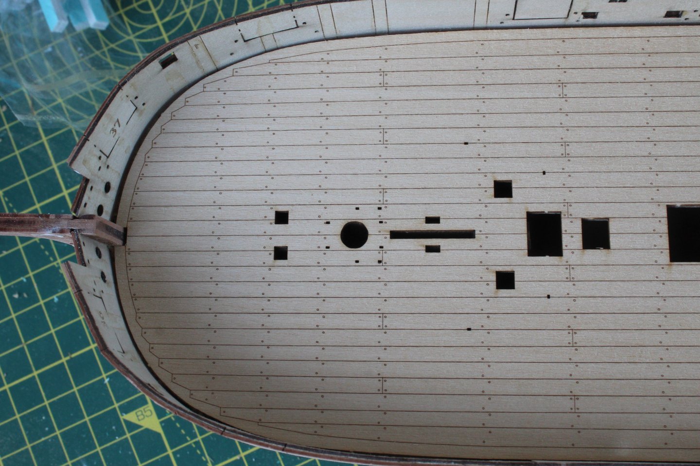
Build Log Index Date: 16/08/2024 Time worked today: 0.5 hours. Total time spent on build: 37.5 hours. Fitting Outer Bulwarks and Test Fit Deck The outer bulwark patterns were fitted without any issue. I brushed plenty of wood glue to the hull and then carefully aligned the outer patterns. A series of clamps were used to hold the patterns, and they were then left overnight to allow plenty of time for the glue to cure. The bulkhead tabs (above the deck level) were then removed using pliers to gently twist. It was then a case of removing any remaining stubs with a craft knife and sandpaper. The laser engraved deck pattern was then test fitted but I did note that the hatch and mast openings were not in complete alignment with the lower deck and that I would need to trim the rear edge. Using some stiff card, I made a template of the aft section of the laser engraved deck so I could trim as necessary. Once the template was perfectly aligned with the deck I was able to mark up and trim the laser etched deck. After trimming the aft section the laser deck was aligned with the lower deck openings and is now ready to be glued.


-
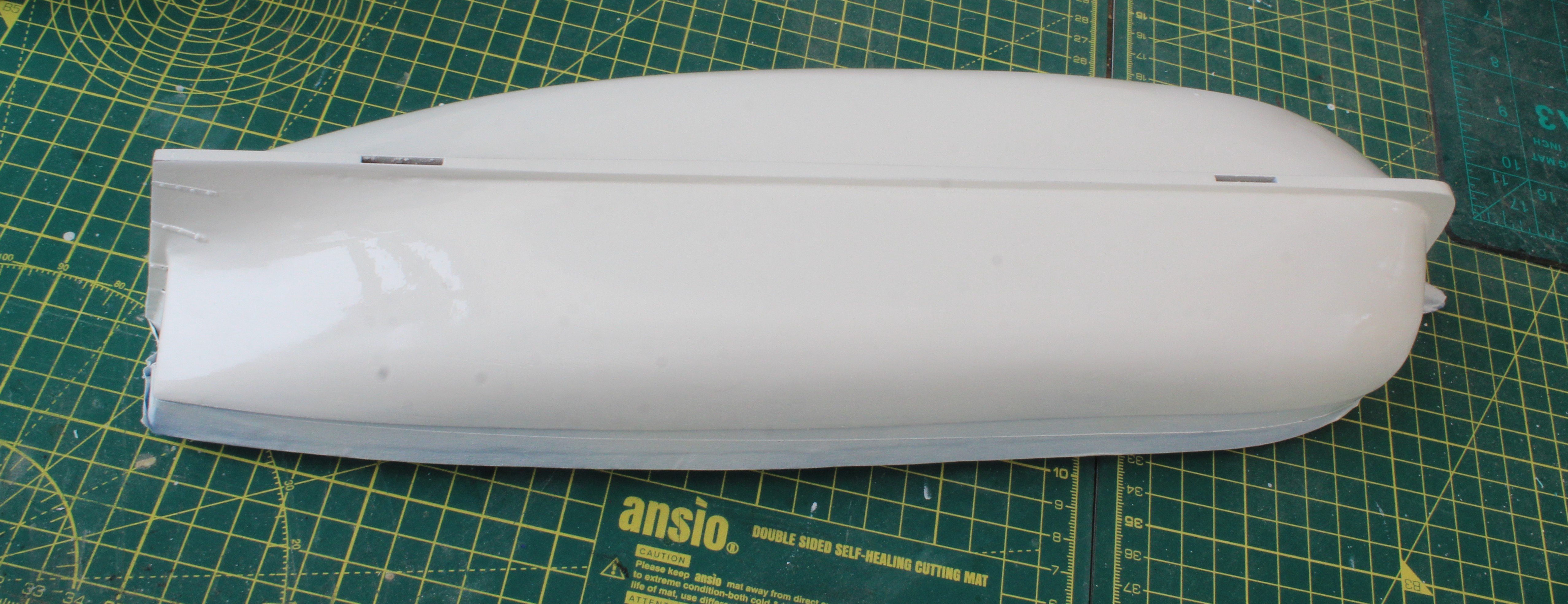
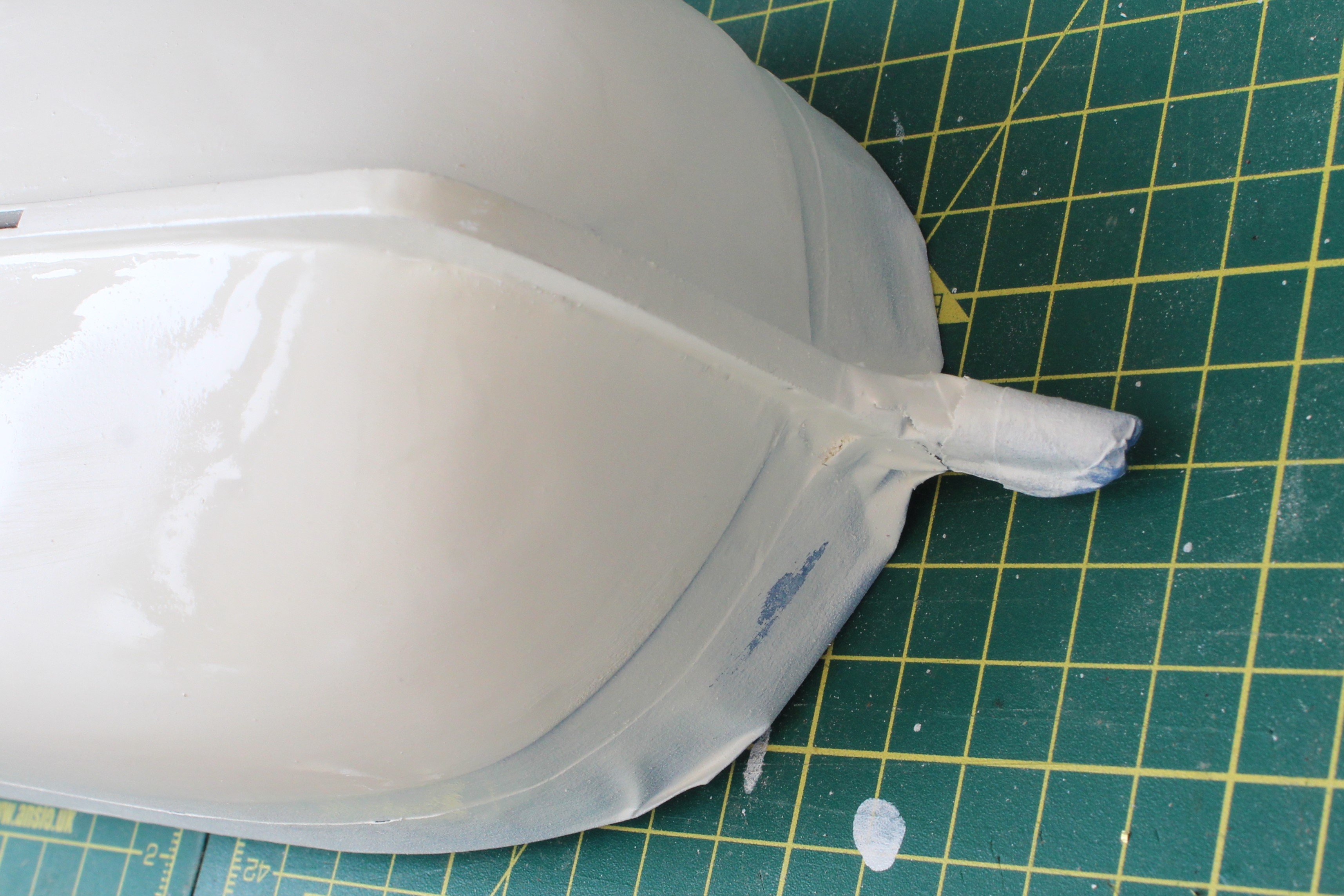
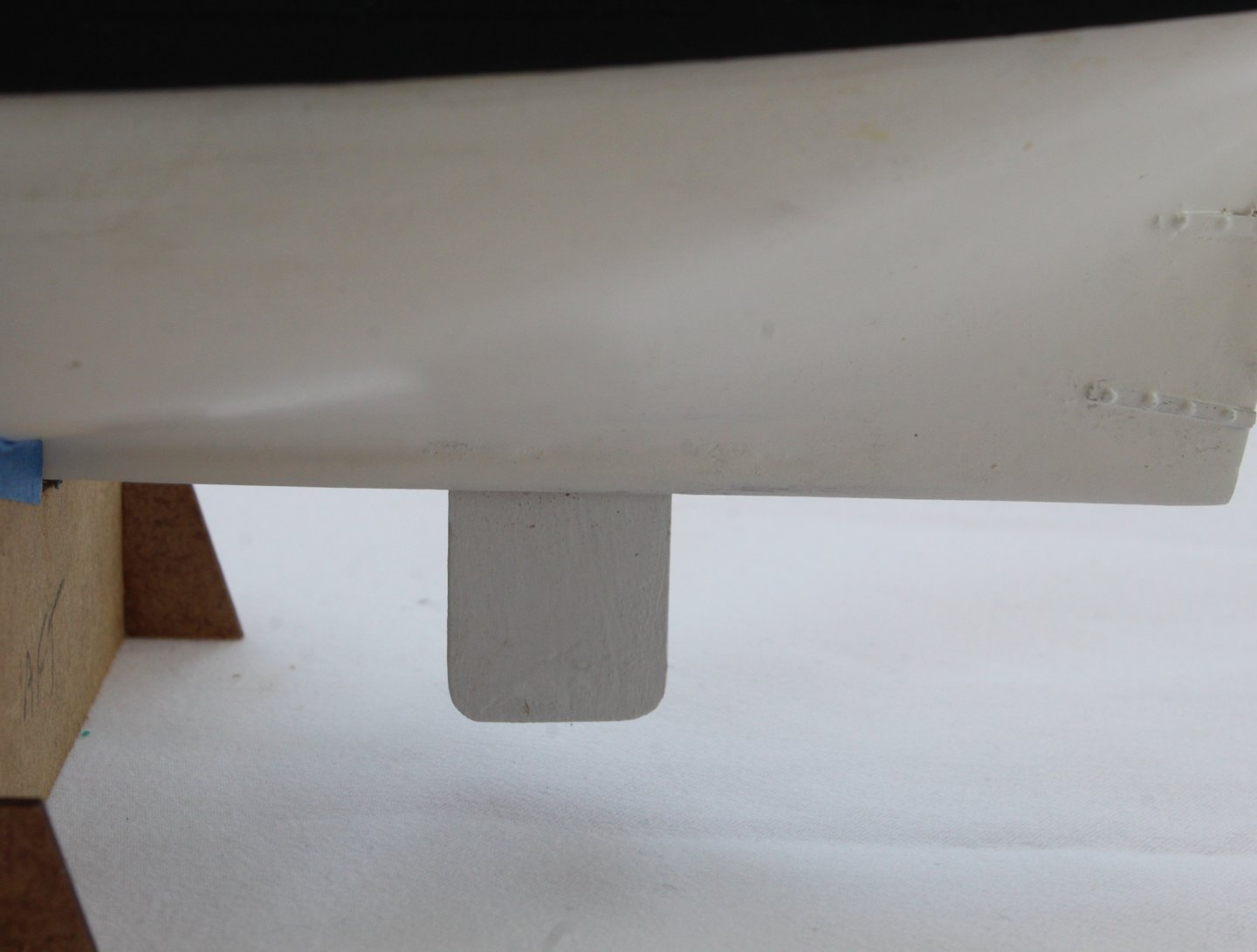
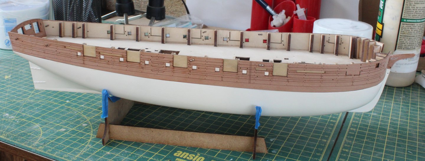
Build Log Index Date: 12/08/2024 - 15/08/2024 Time worked today: 2 hours. Total time spent on build: 37 hours. Painting The Hull Continues The hull has now had a few iterations of the painting process and as I indicated in my last post it is not a task that can be rushed. After each coat of paint had been applied, I continued sand and apply filler where necessary. Once I was reasonably happy with how the hull was looking the rudder strap PE parts were added. Cut down pins were then inserted in rudder strap holes. After a couple more sprays of paint the hull is now looking good. I am hoping that once the paint has dried there will be no more worked required. The paint is still wet in the attached photo’s hence the shiny nature and reflections.
-
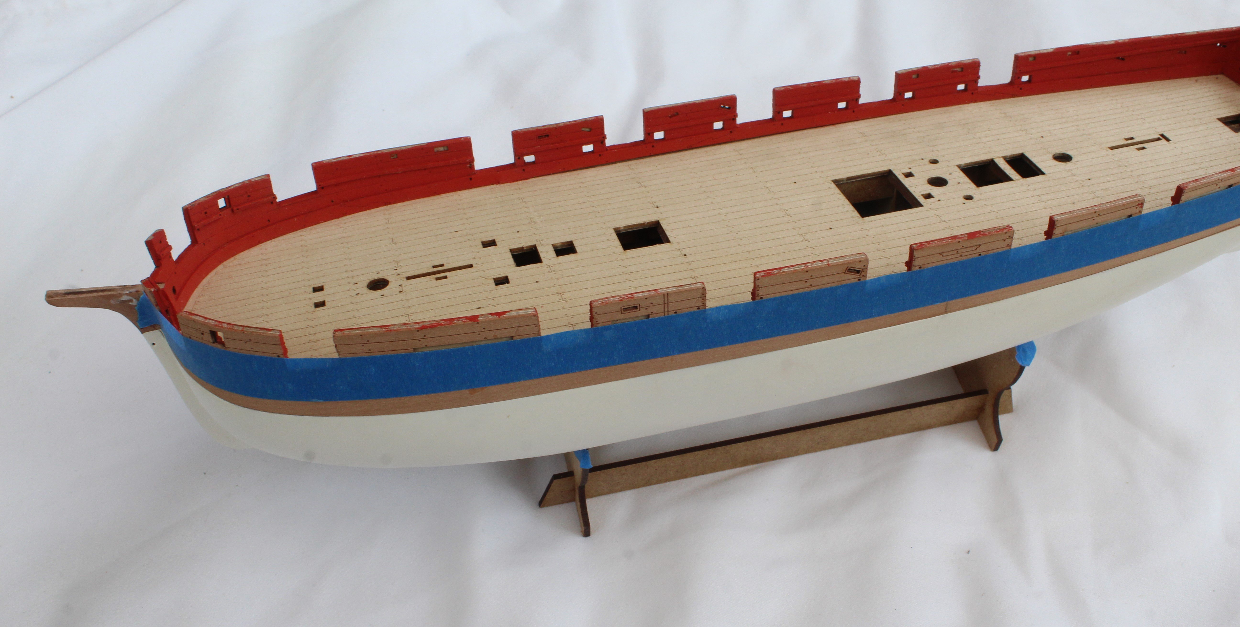
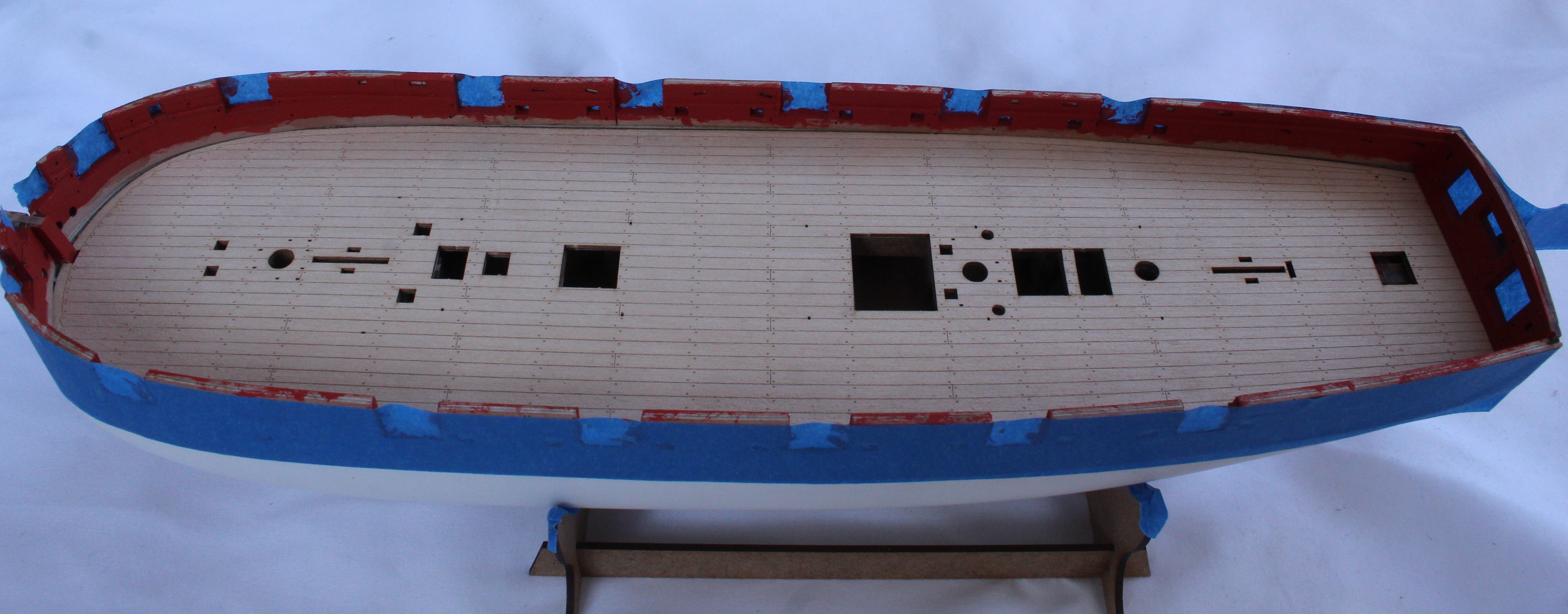
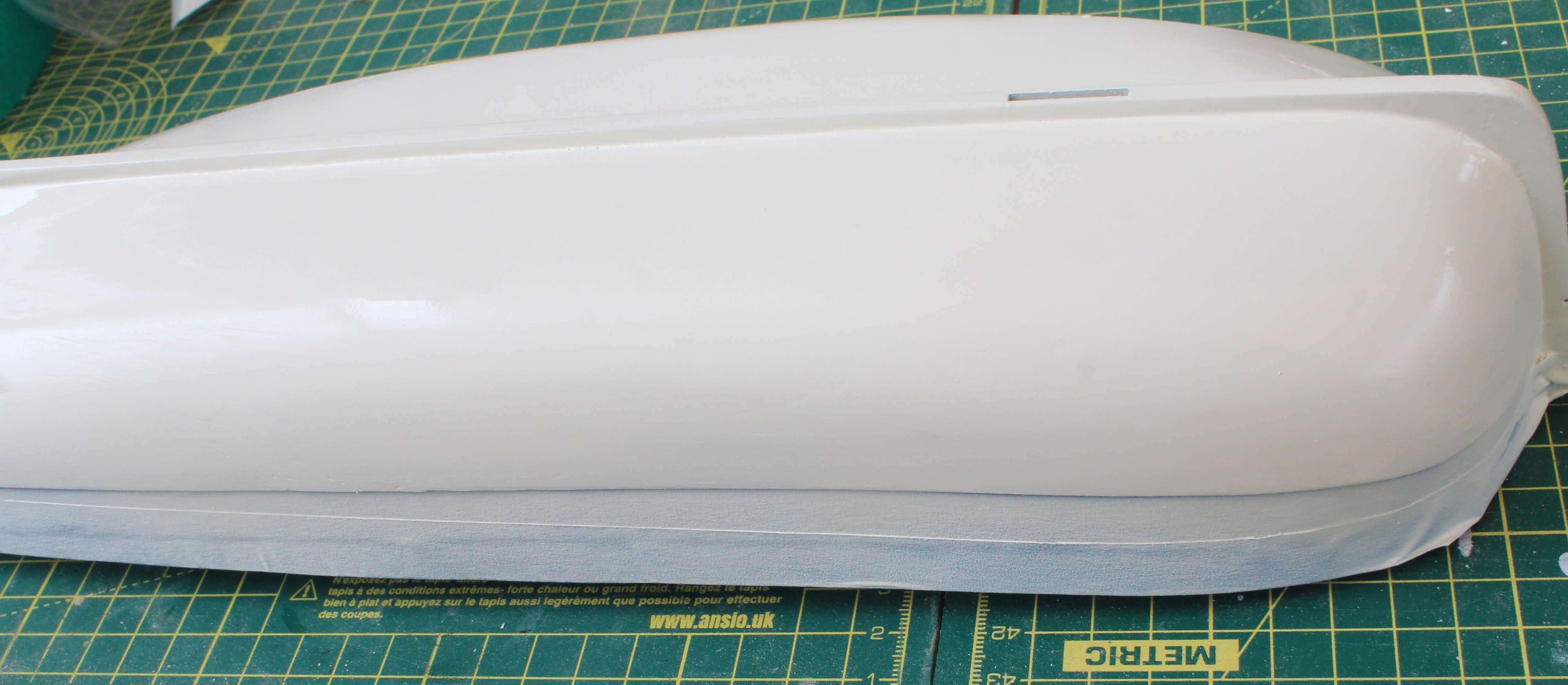
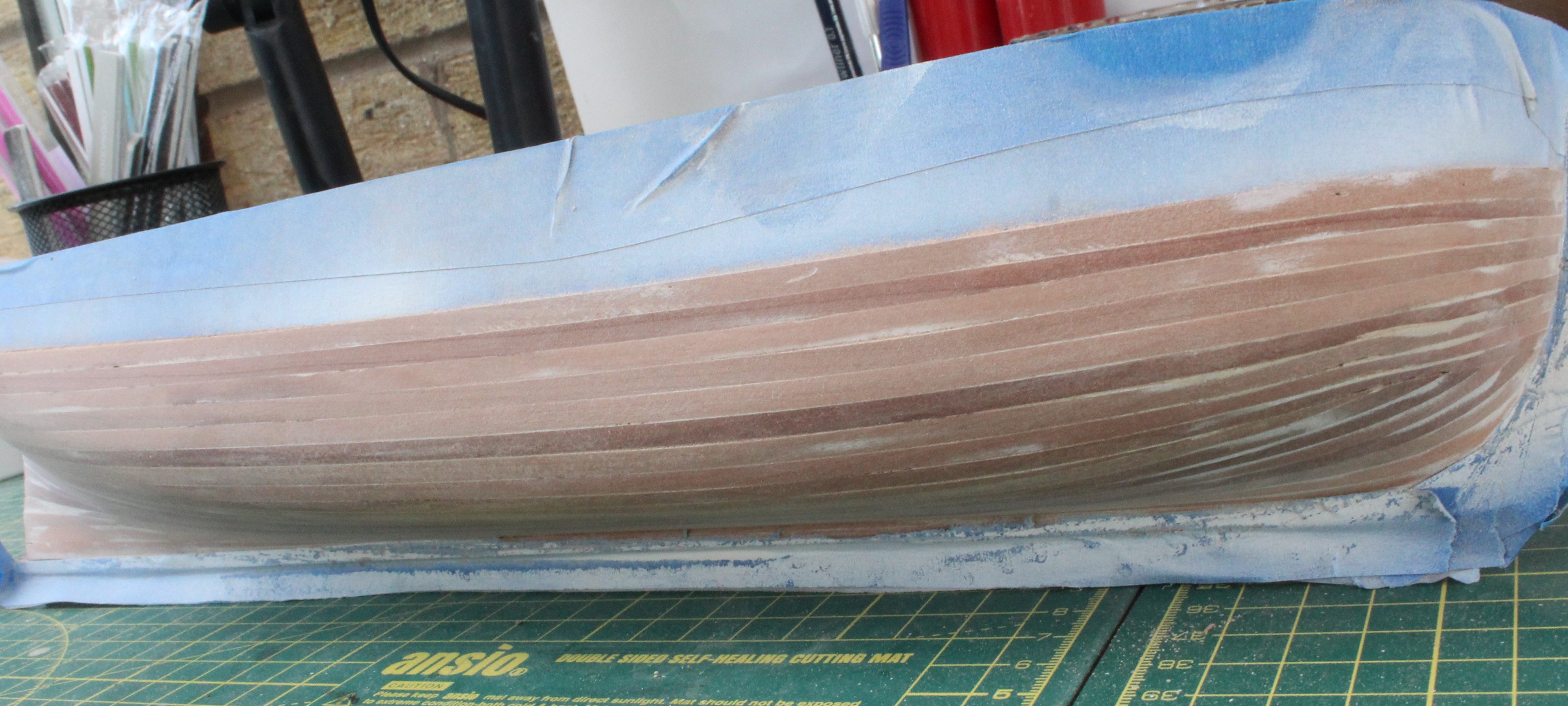
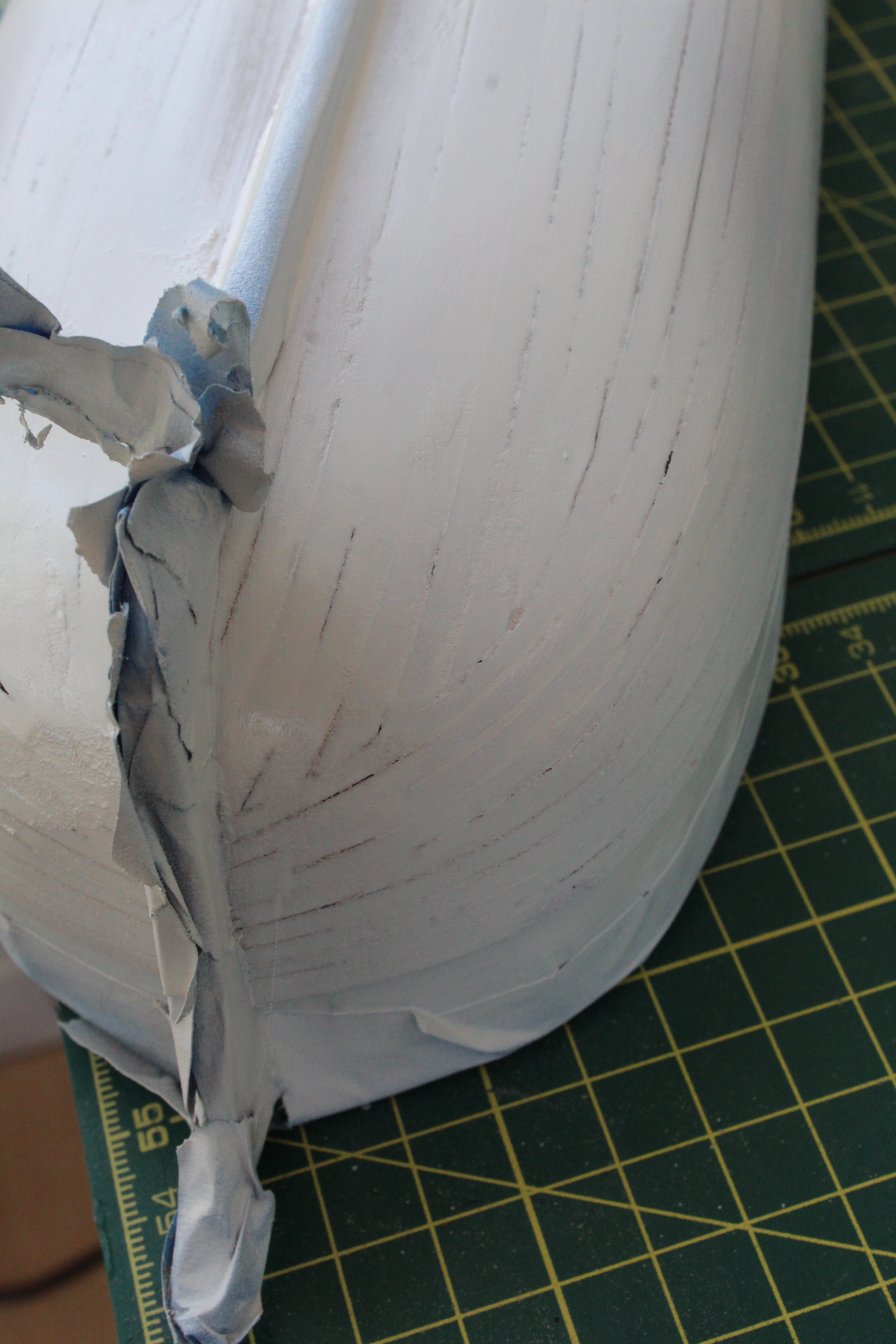
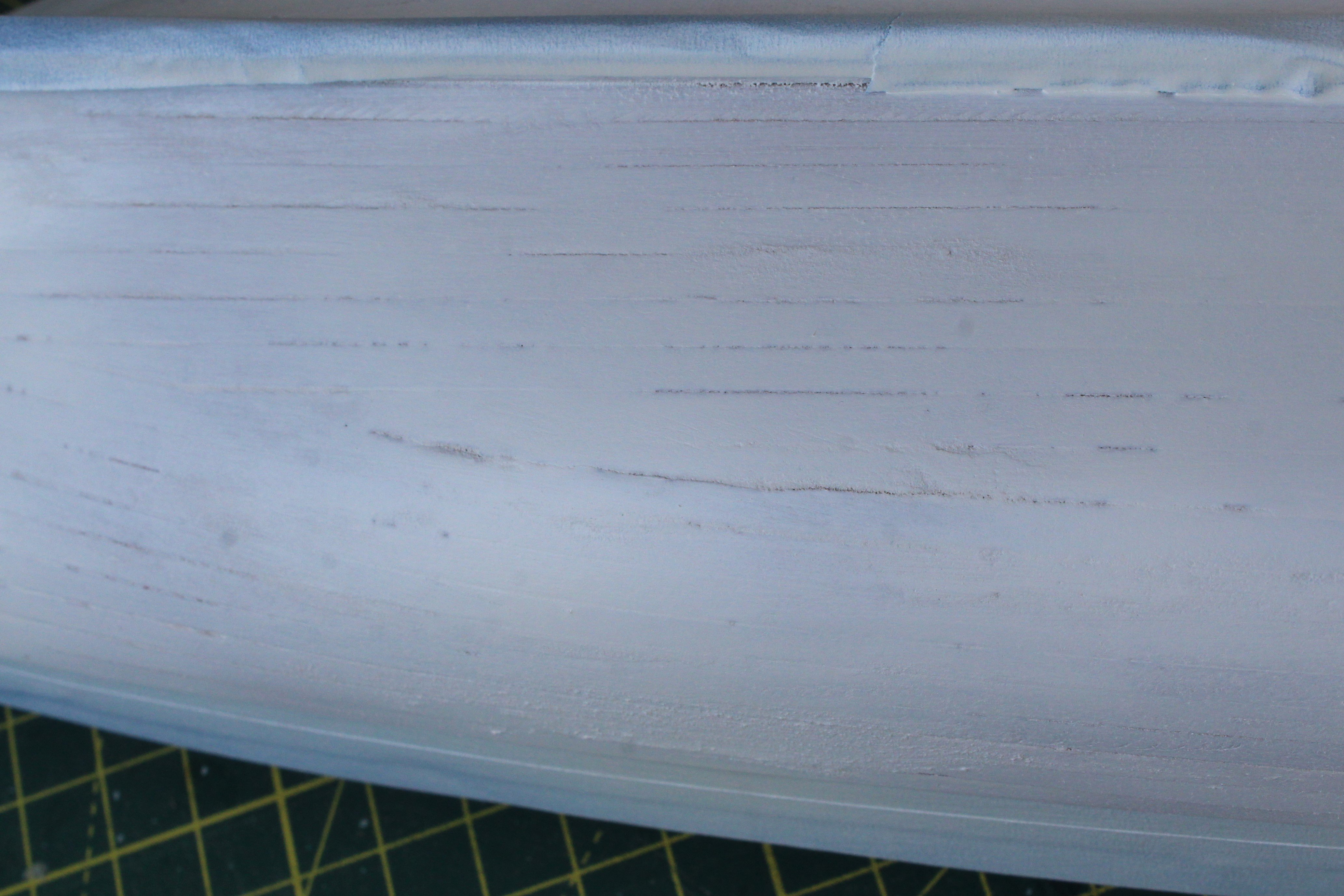
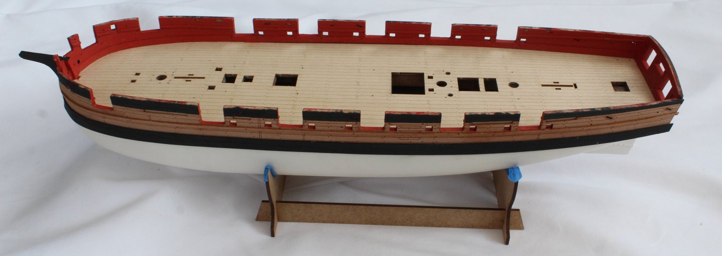
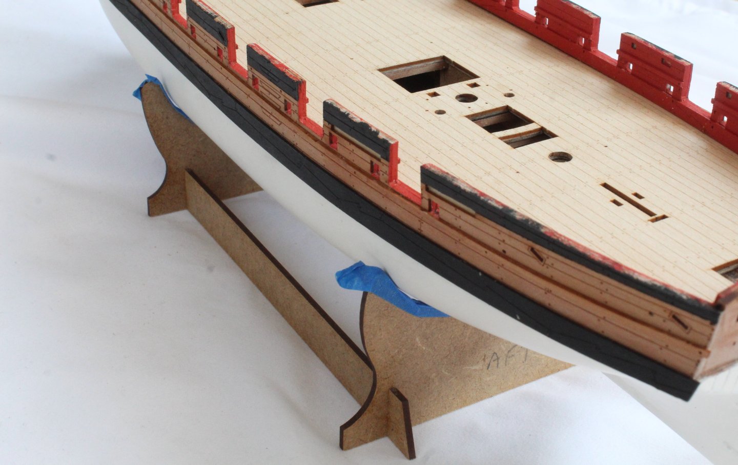
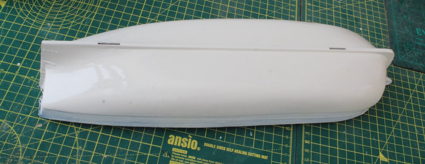
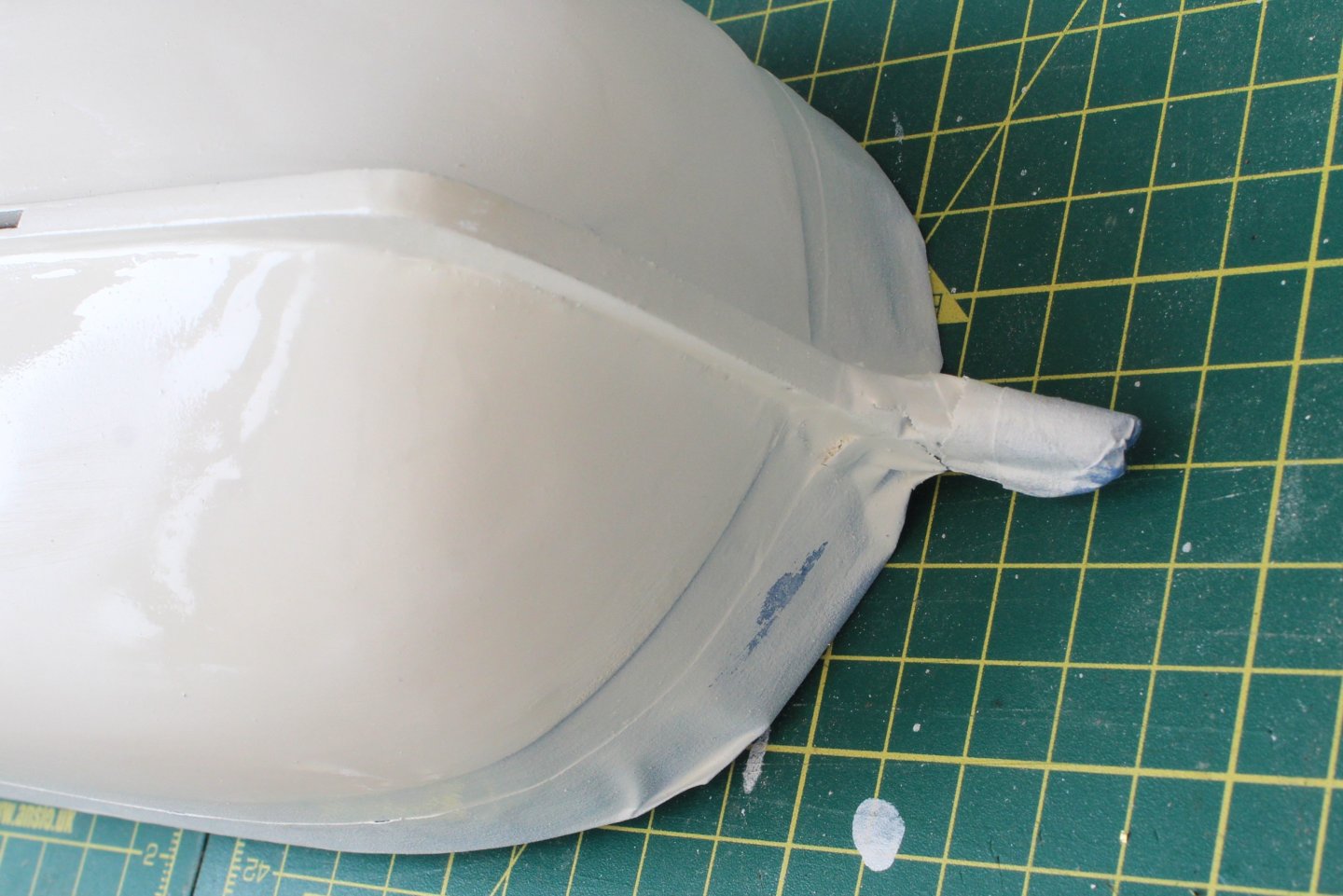
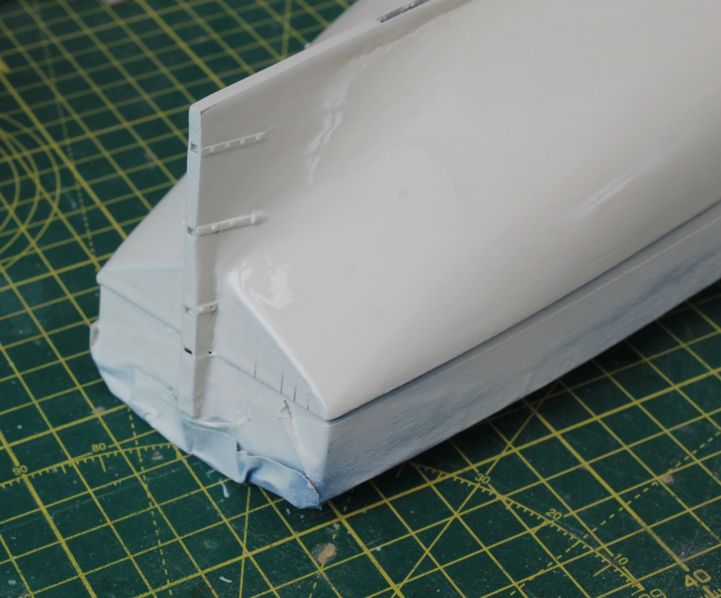
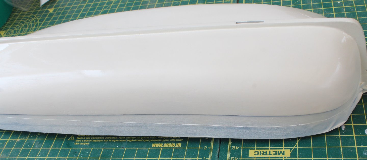
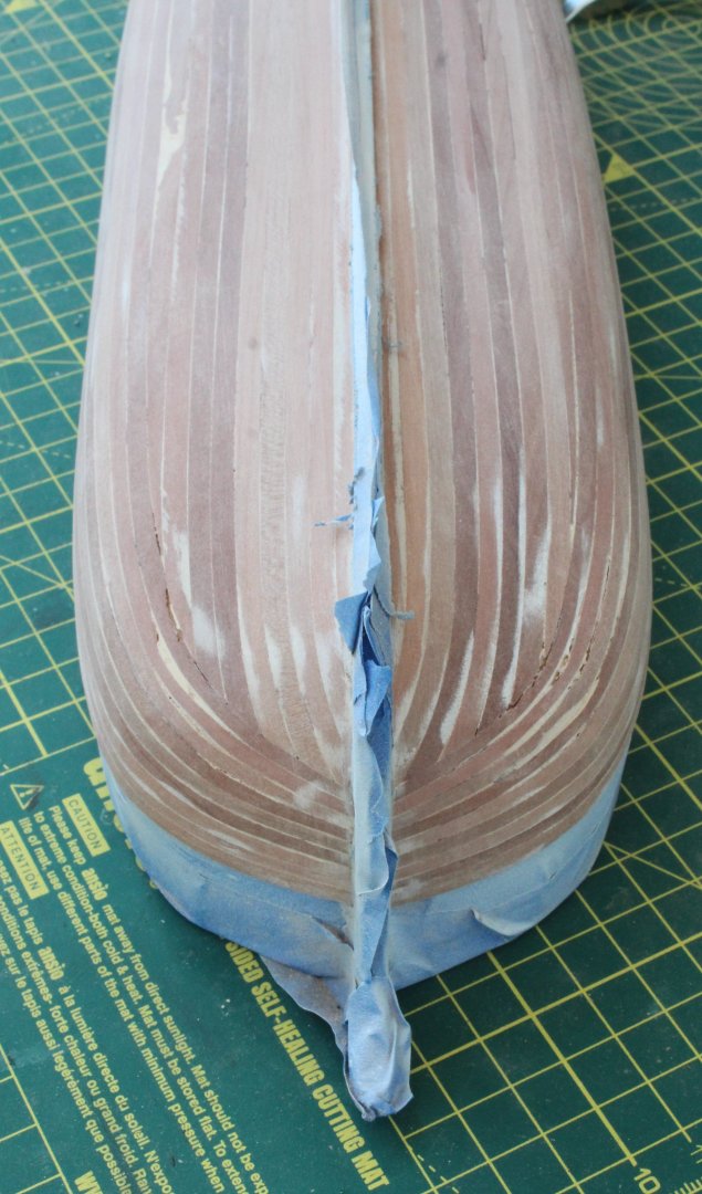
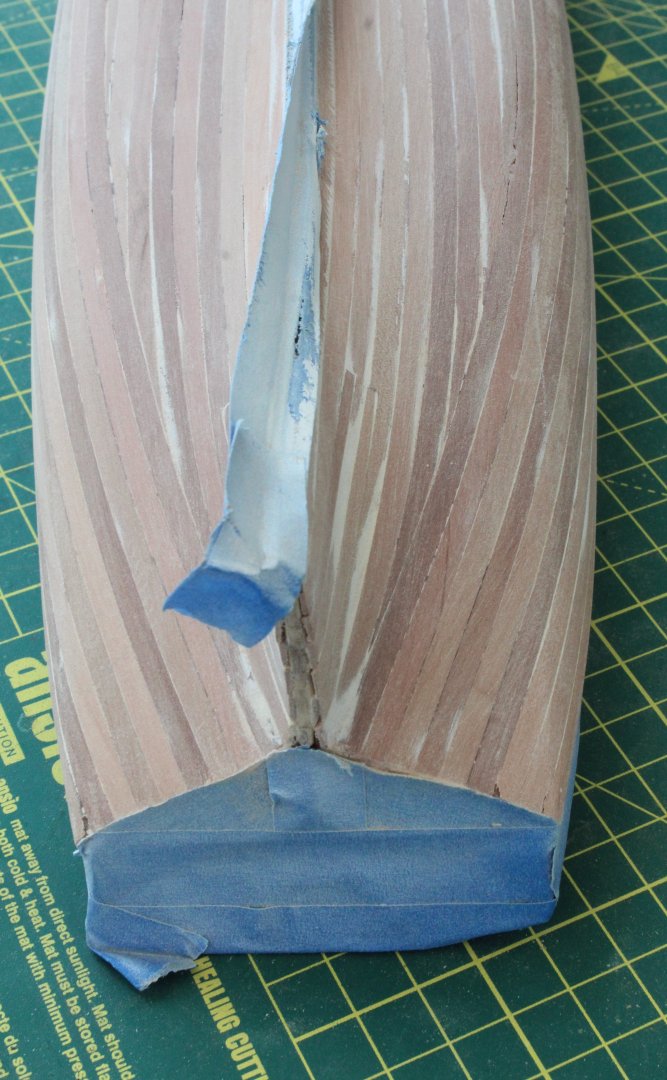
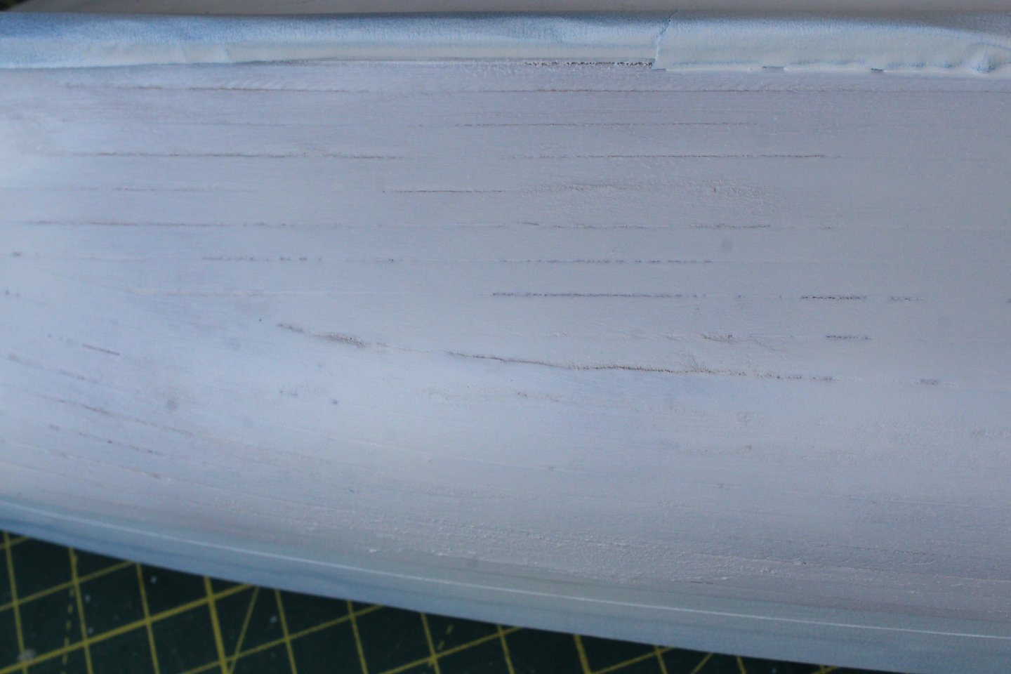
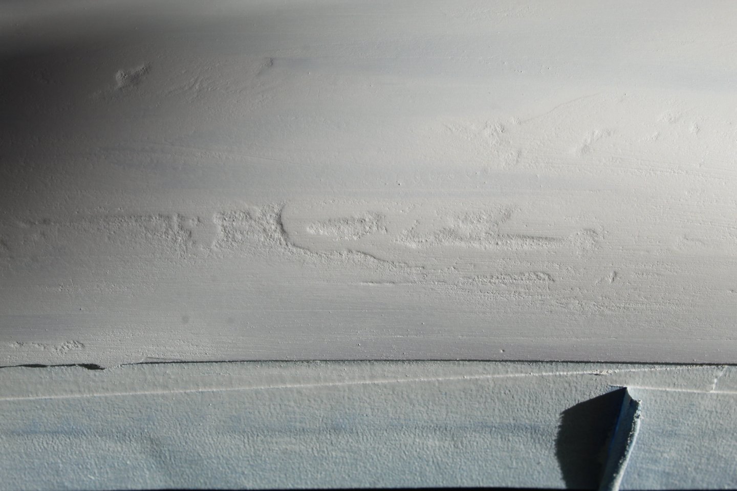
Build Log Index Date: 10/08/2024 & 11/08/2024 Time worked today: 2 hours. Total time spent on build: 35 hours. Sanding. Filling and Painting The Hull It takes time and patience to sand, fill and paint the hull, requiring a few iterations of the process. It is not a task that can be rushed. Prior to starting work I used tape to protect the patterns. I then brushed a diluted mixture of wood filler to the hull so that all the little gaps between planks were filled. I also added more filler to the visible depressions in the planking. Once the filler had hardened the hull was given a light sand with some 120-grit sandpaper to remove the excess filler. The hull was the giving a light spray of white paint. Using my palm sander fitted with 80-grit sandpaper and then 120-grit sandpaper the hull was sanded smooth again. The aim is to remove as much as the white paint as possible which indicates the hull smooth. As can be seen in the photos below there are still a few areas which will require some filler. After filling and sanding the hull once again another coat of white paint was sprayed on the hull. As can be seen in the next photo’s there is still a bit more filling work required but the hull is starting to look better. After filling the gaps with more diluted filler and then sanding smooth again another coat of white paint was sprayed on. The hull is now looking good but it will require another round of sanding and filling as there are still some imperfections. Once the hull has been sanded and filled I plan to add the stern post and the stern transom (upper outer) pattern to the hull before I start the formal painting process.


-
Many thanks Uwe.
-
Many thanks Bob.