HOLIDAY DONATION DRIVE - SUPPORT MSW - DO YOUR PART TO KEEP THIS GREAT FORUM GOING! (89 donations so far out of 49,000 members - C'mon guys!)
×


Glenn-UK
-
Posts
3,163 -
Joined
-
Last visited
Content Type
Profiles
Forums
Gallery
Events
Everything posted by Glenn-UK
-
 Hello Mark Planking is one of the dark arts and I am making progress in making a better job of it. The light bulb moment for me was when I finally understood the lateral bending method and the benefit adding twists to planks for the garboard. Cheers Glenn
- 241 replies
-
- 2
-

-
- Vanguarrd Models
- Harpy
- (and 1 more)
-
Hi Ross Thanks for the comment. I am still trying to figure out proper planking also. Cheers Glenn
-
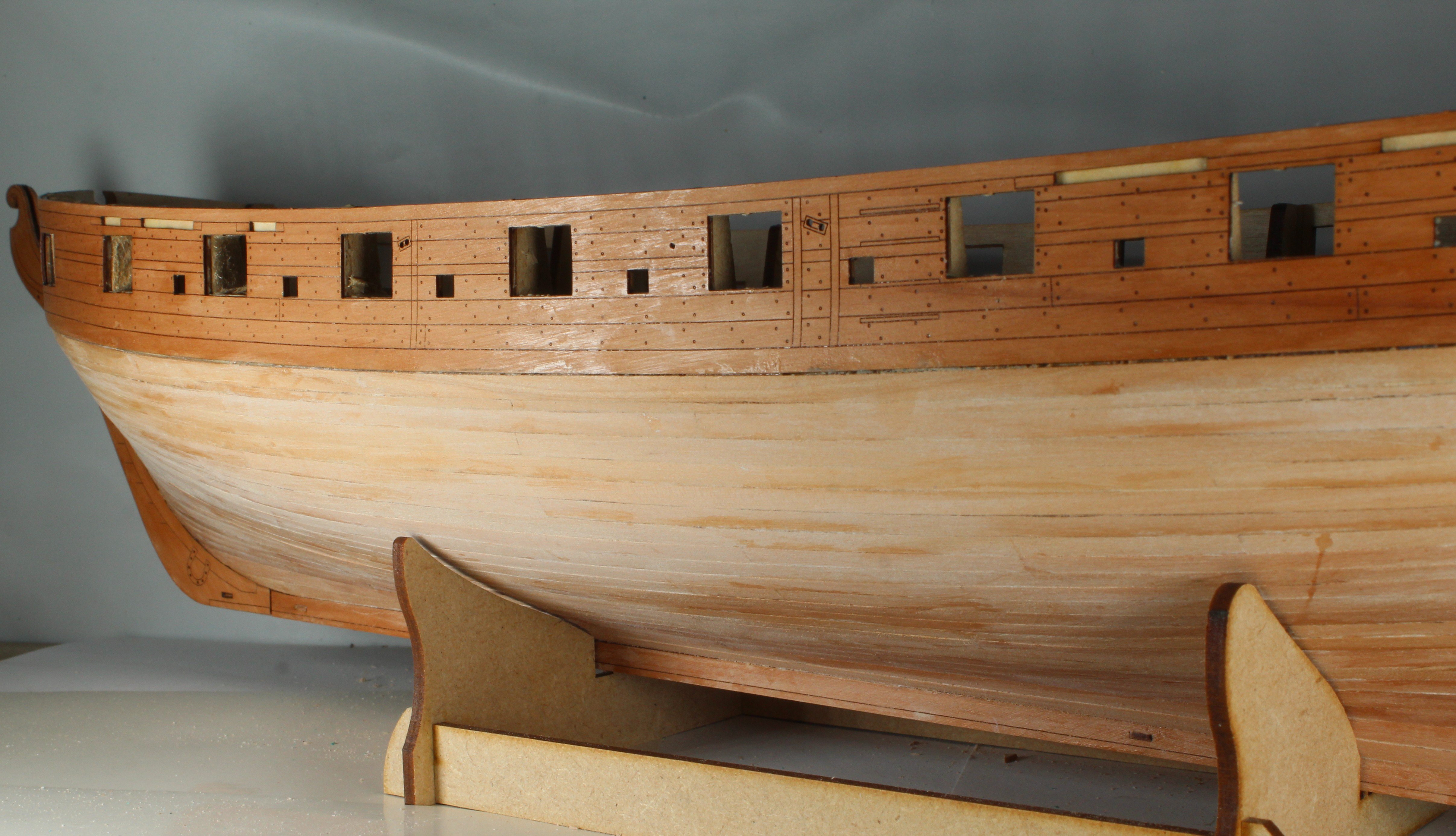
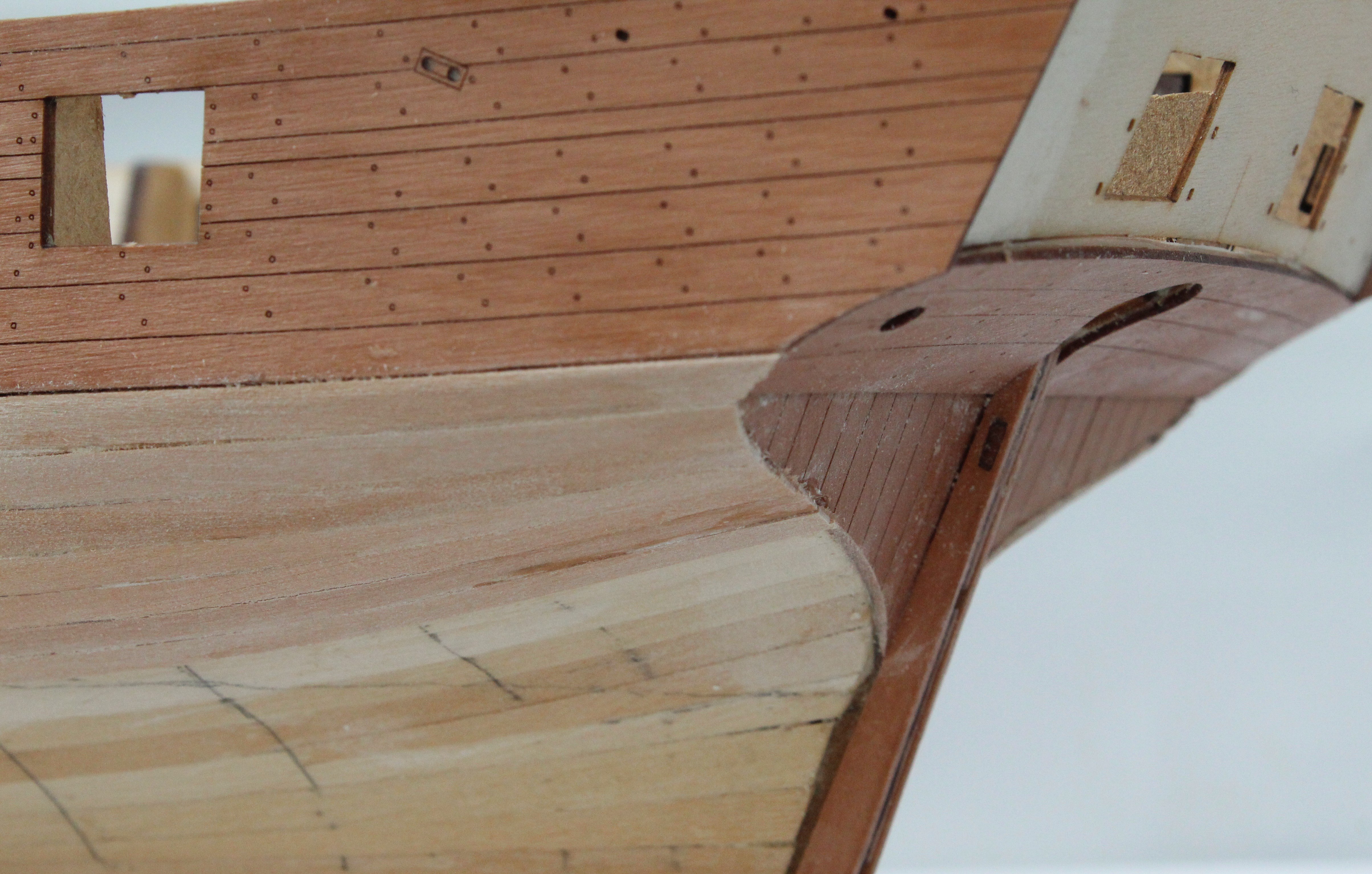
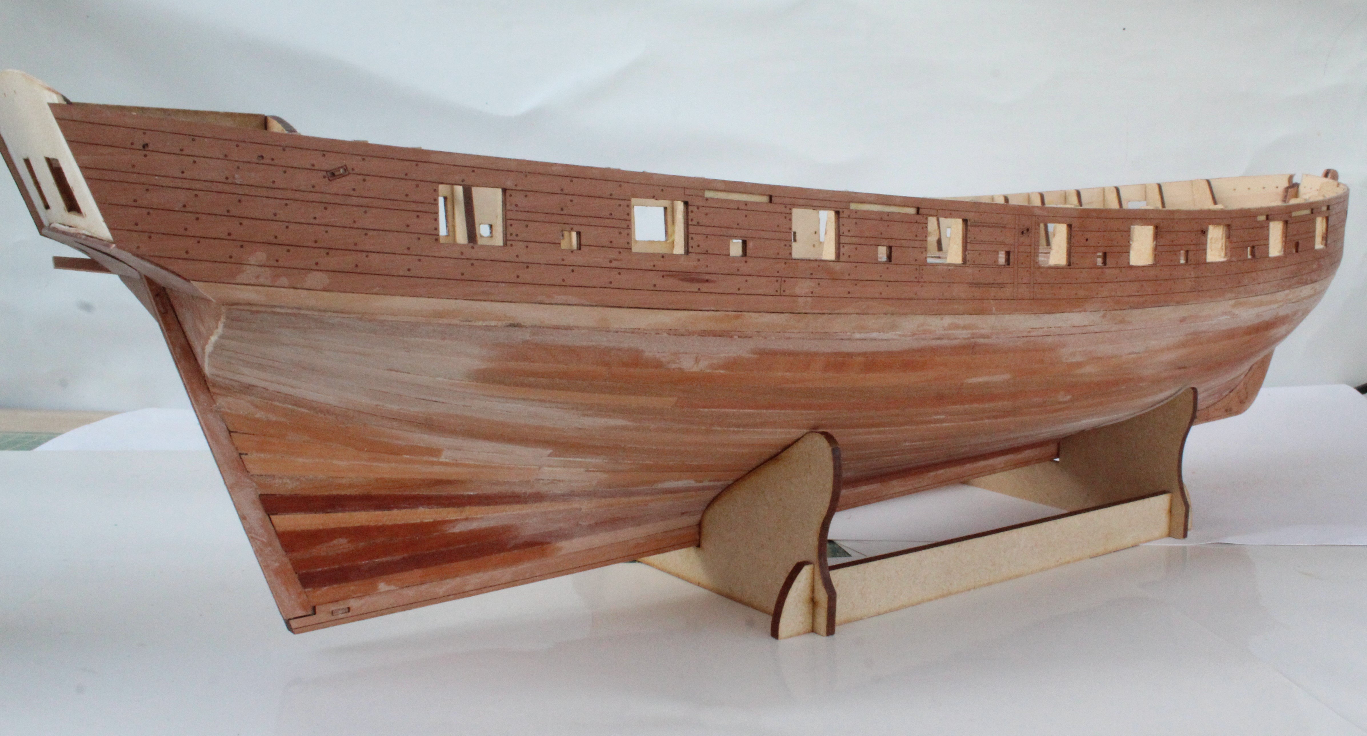
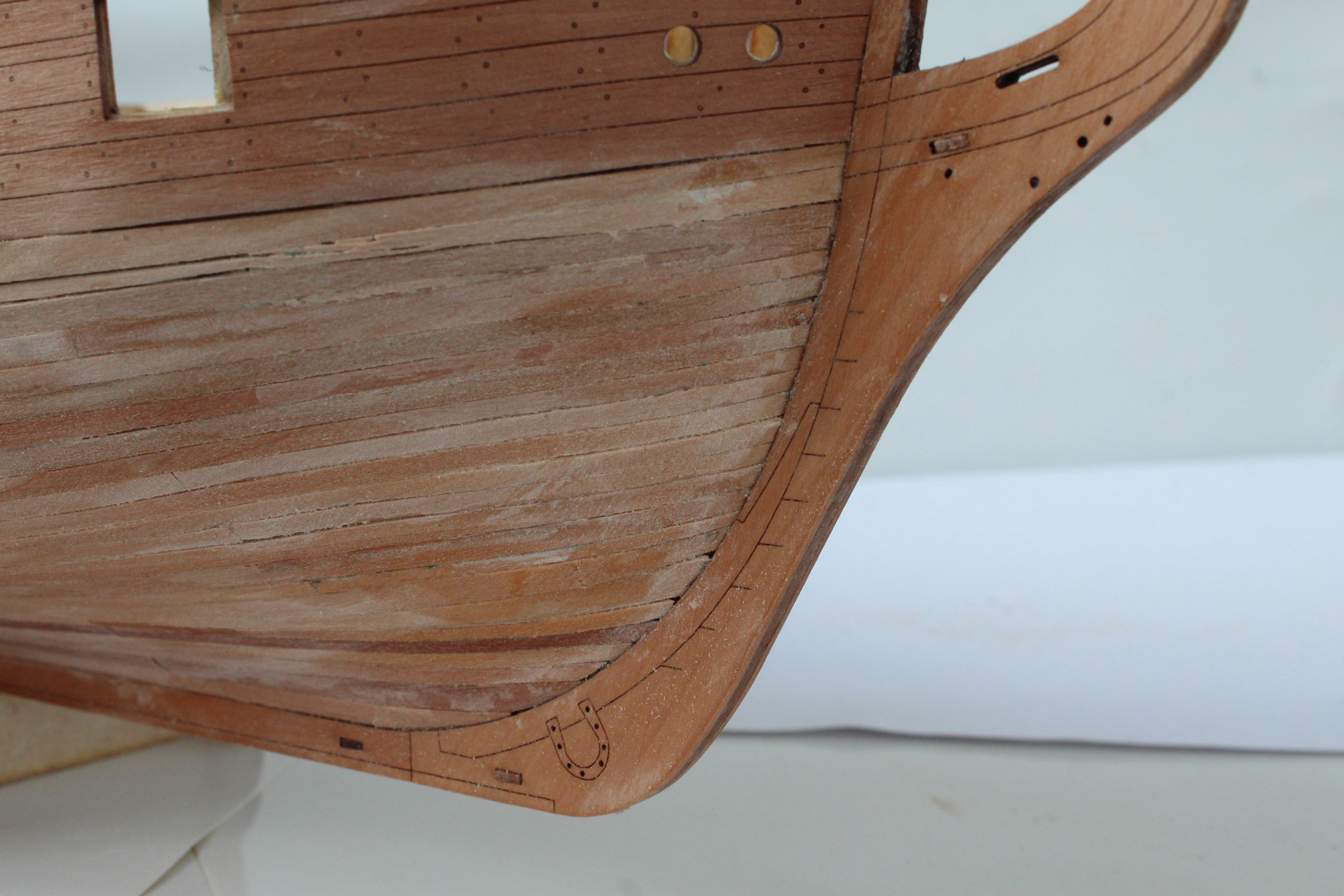
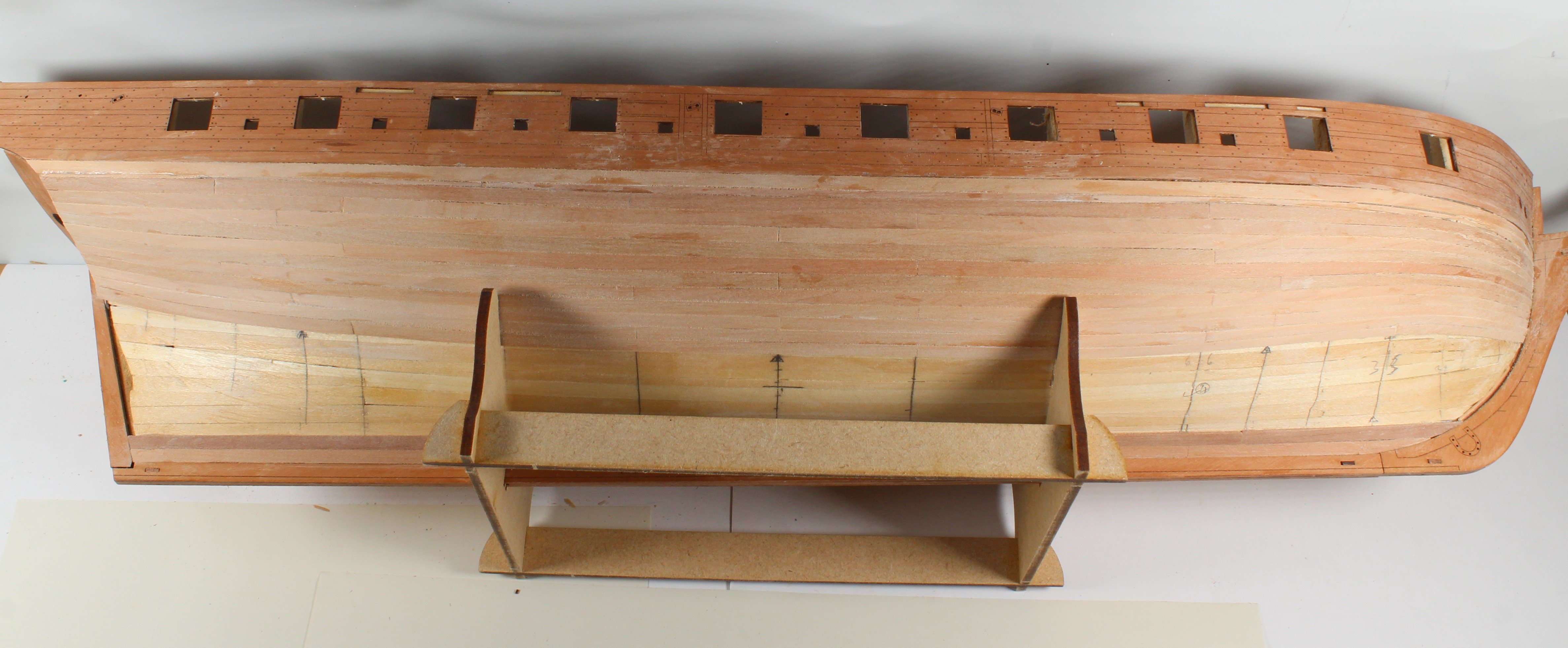
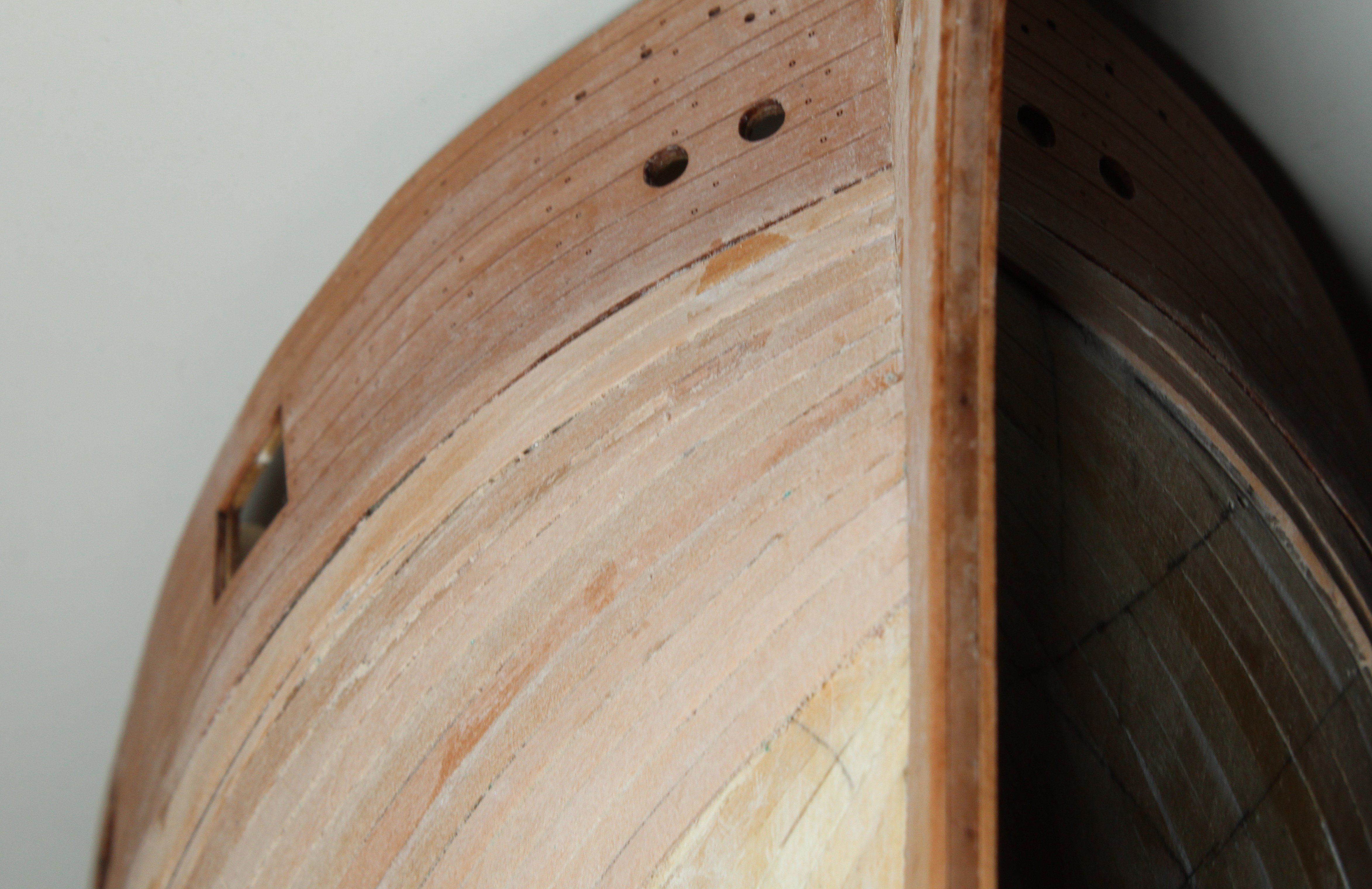
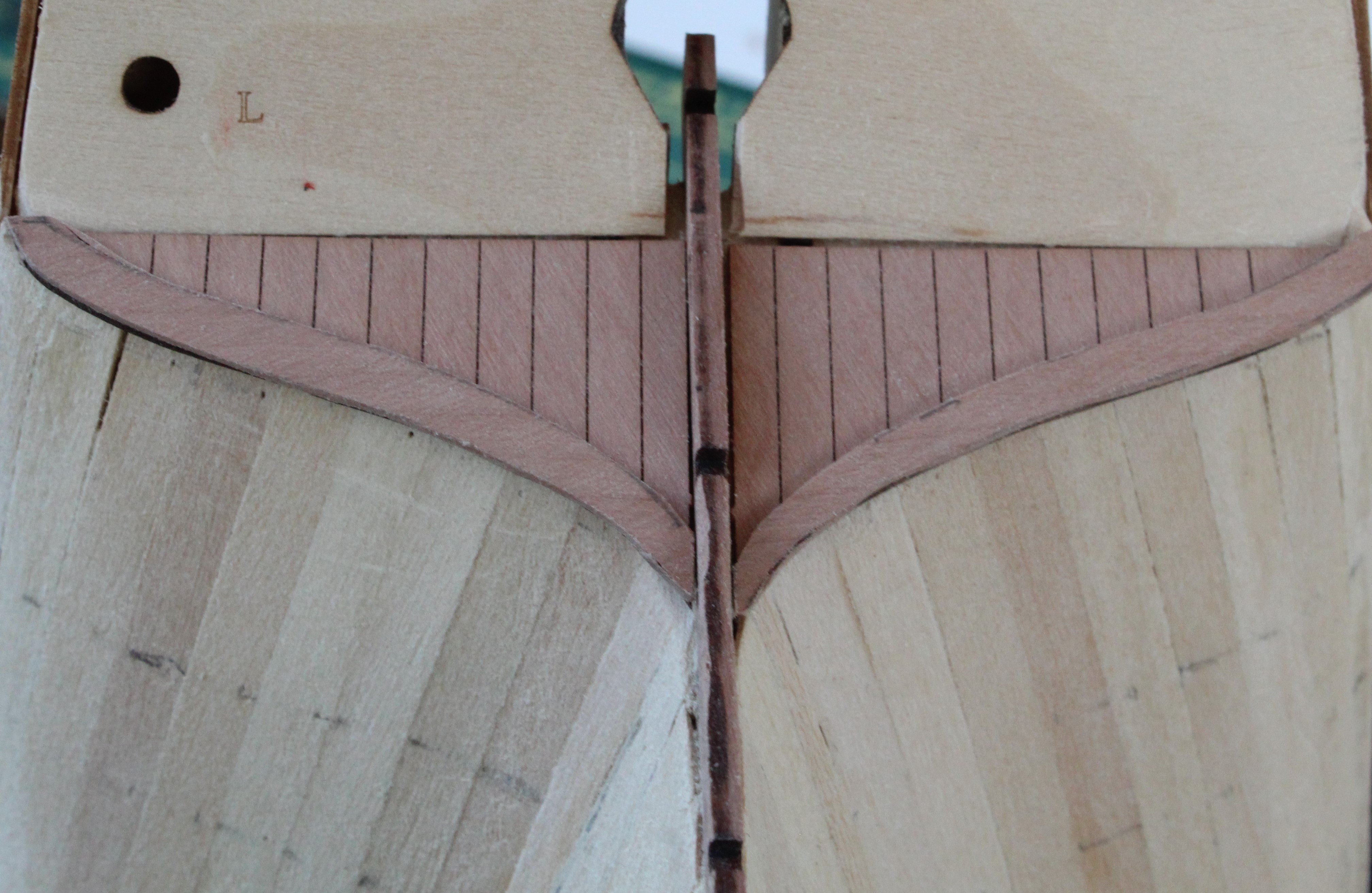
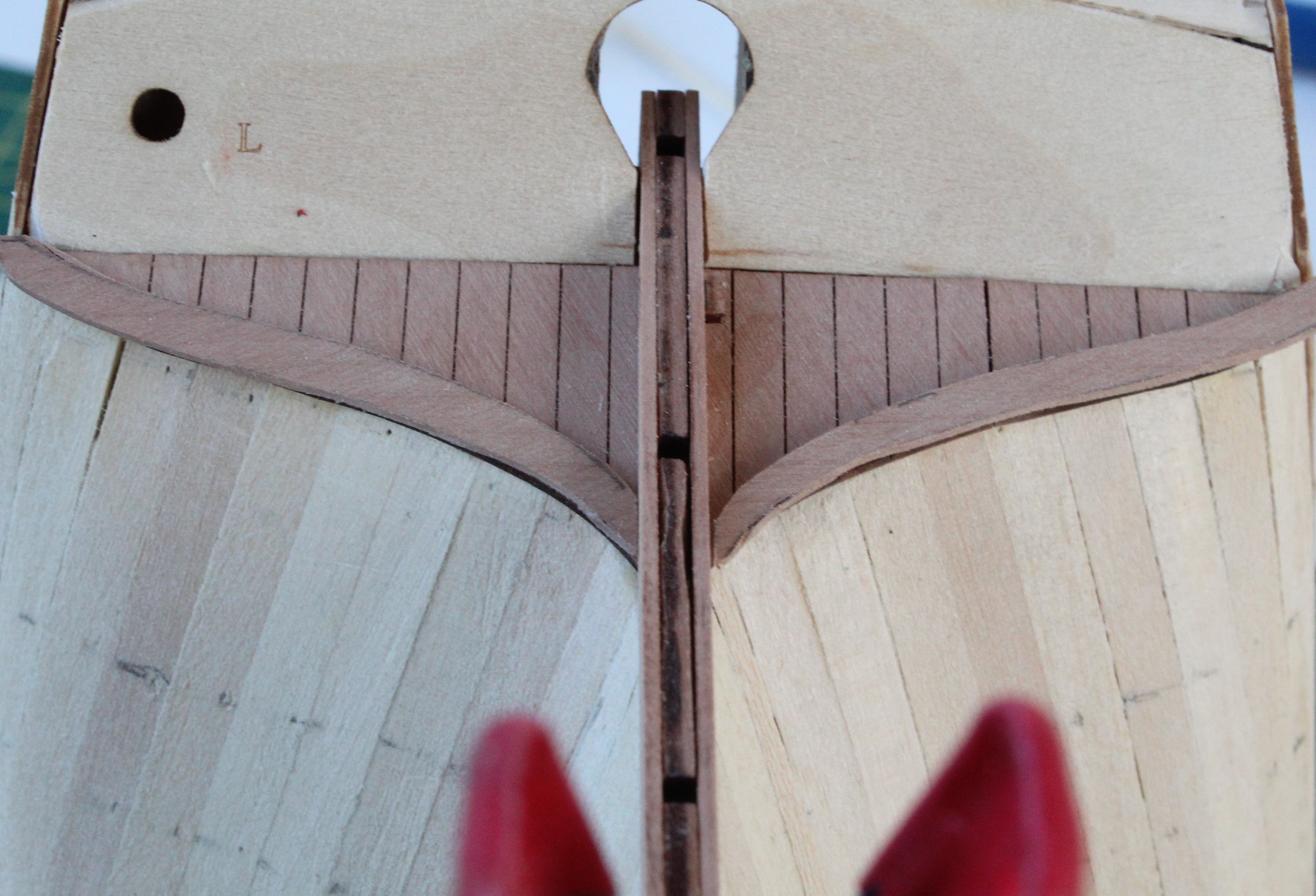
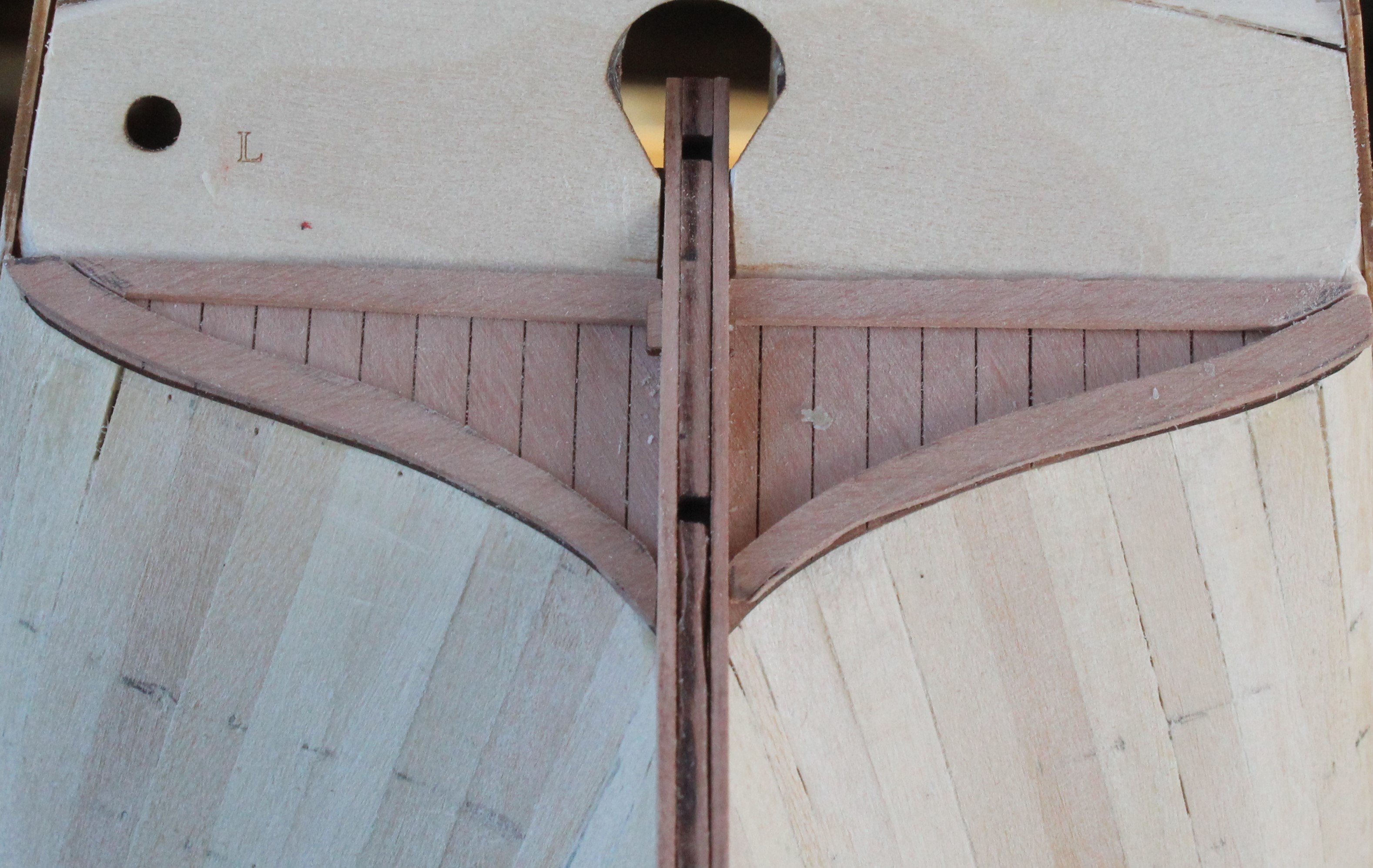
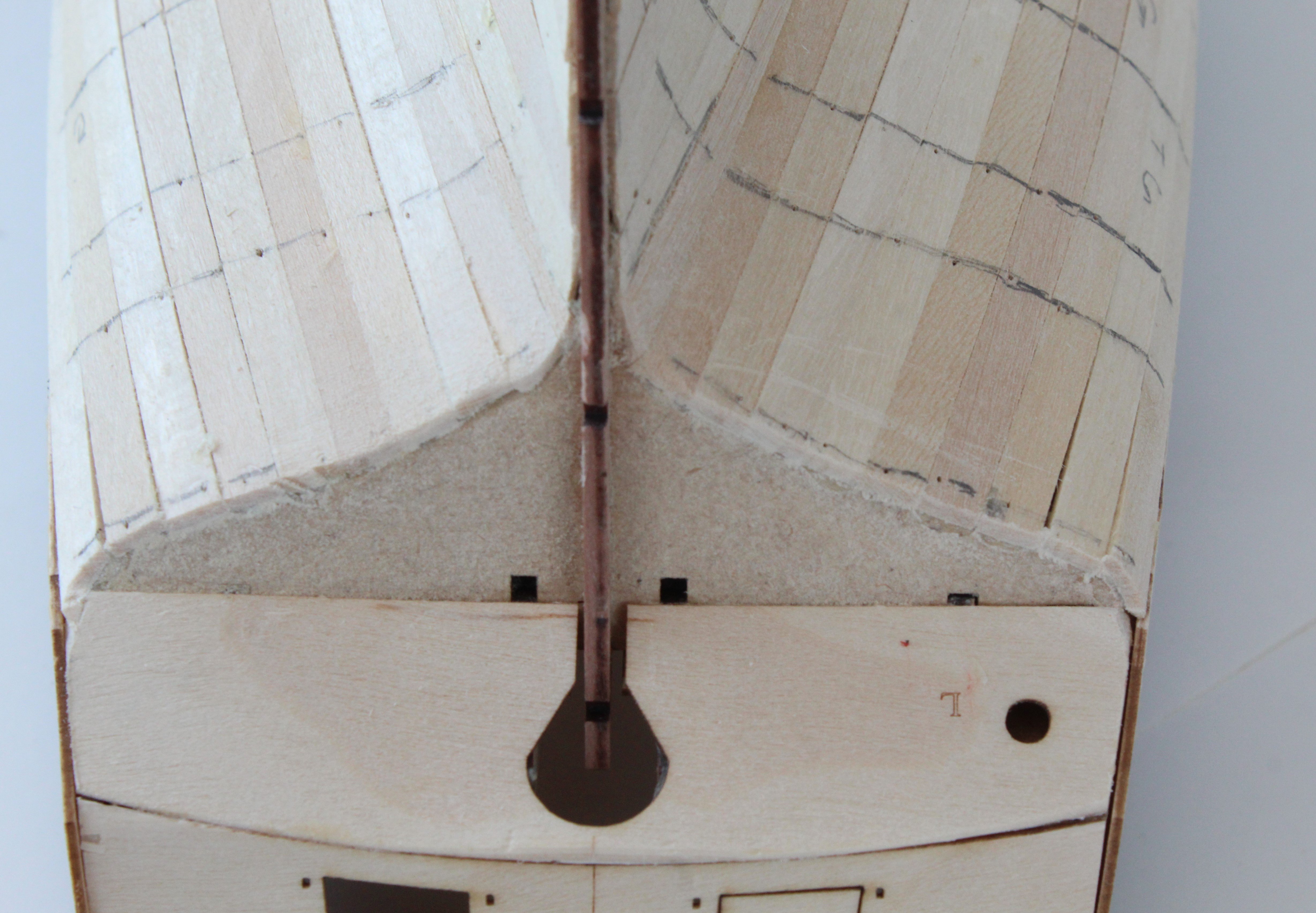
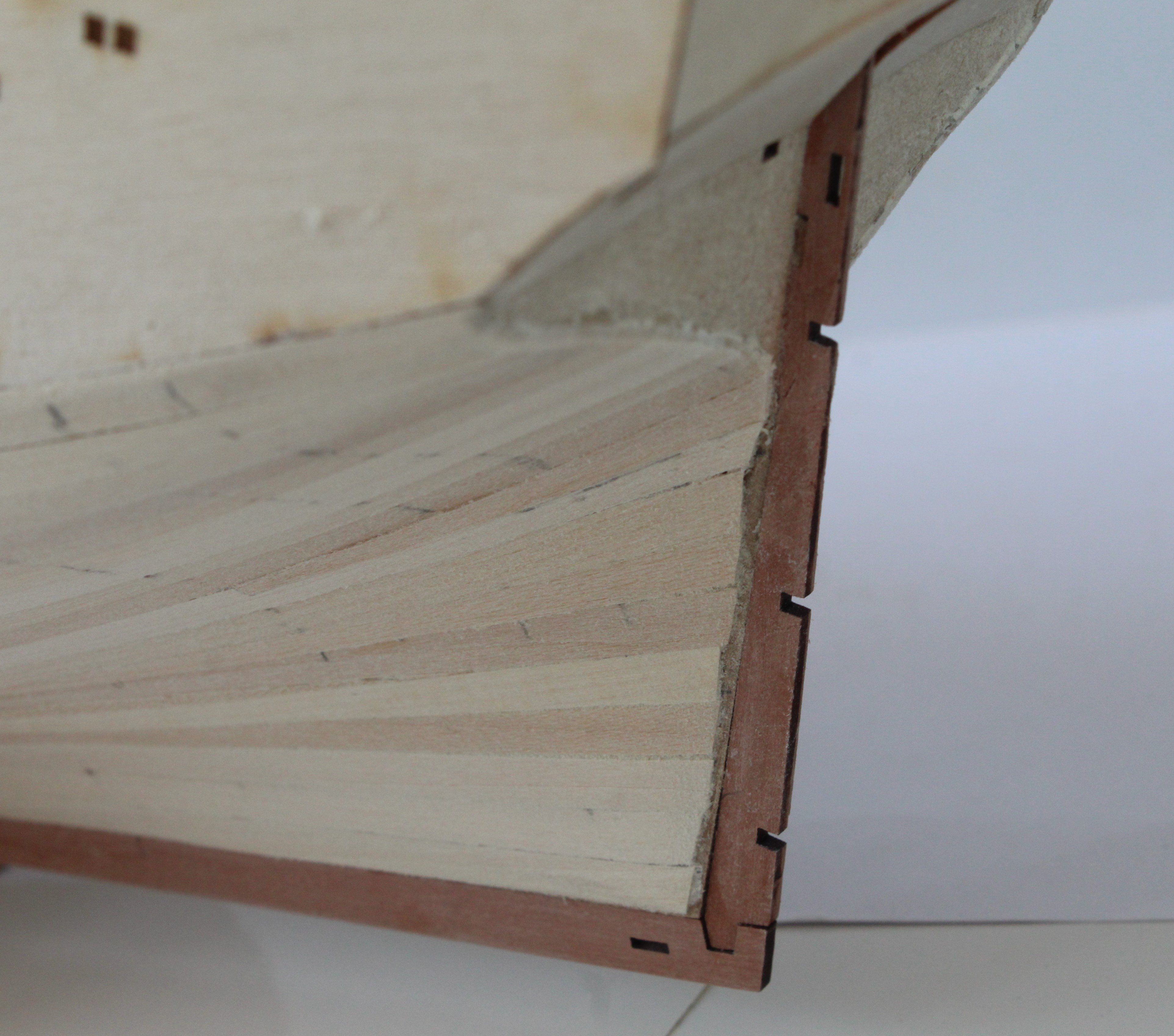
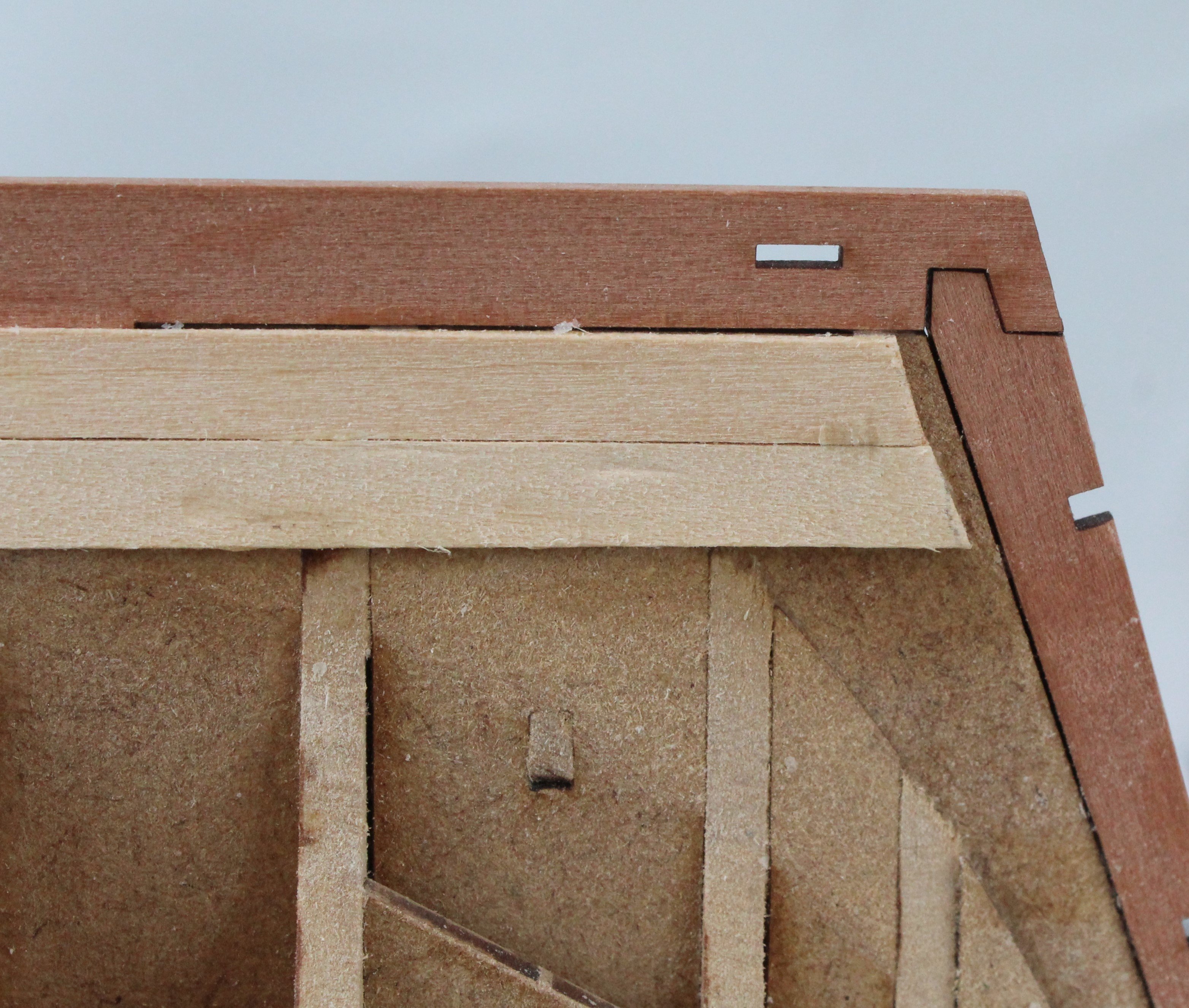
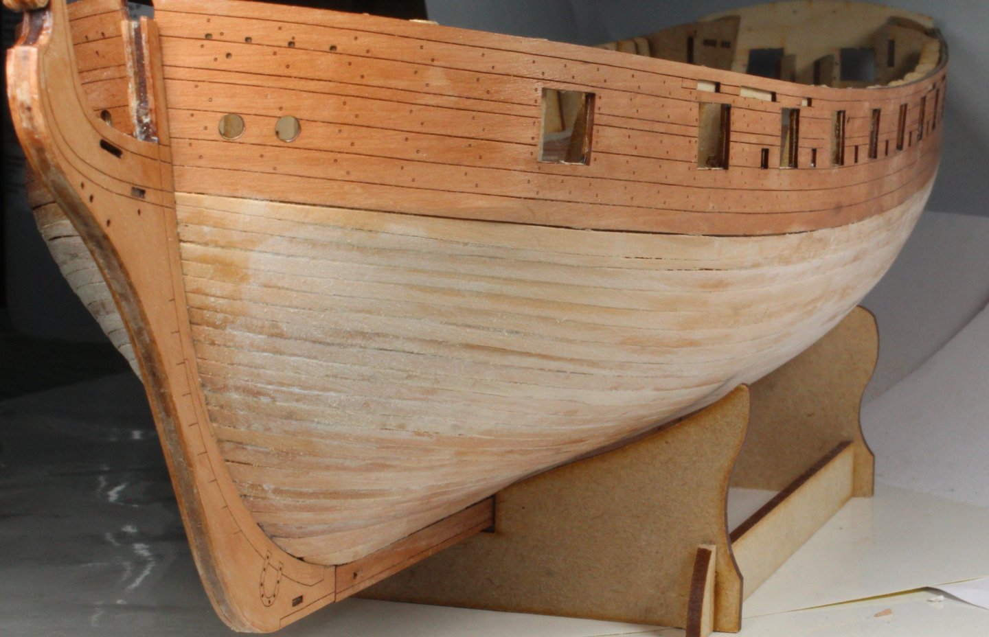
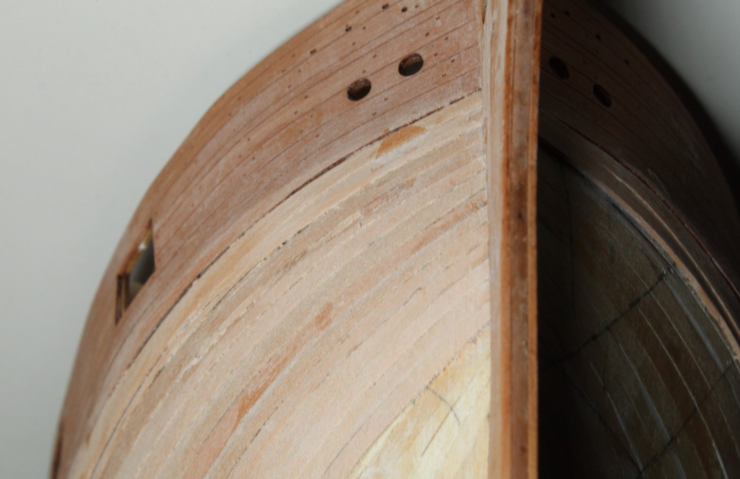
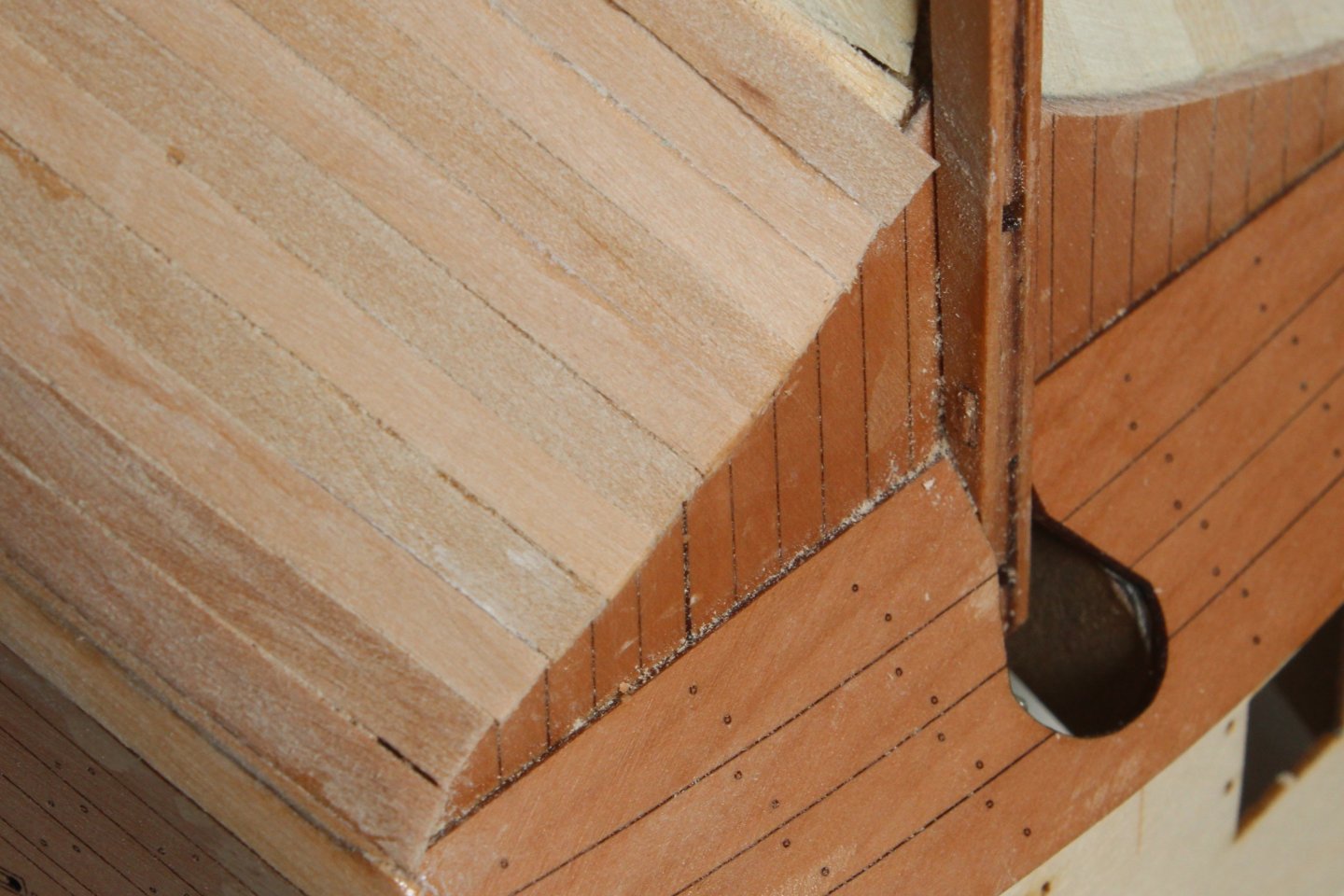
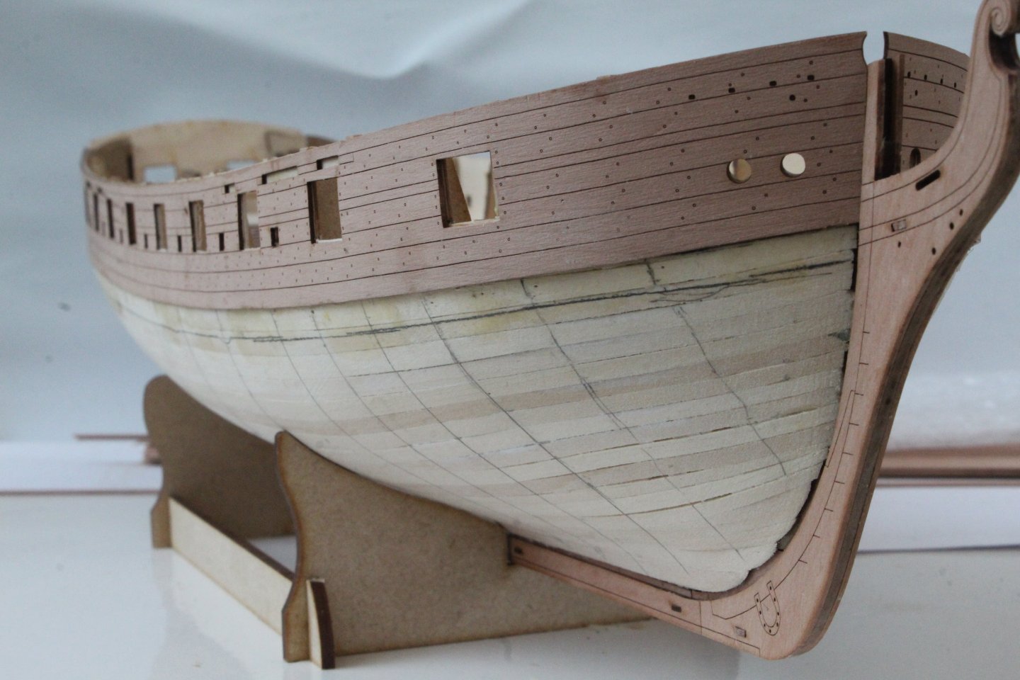
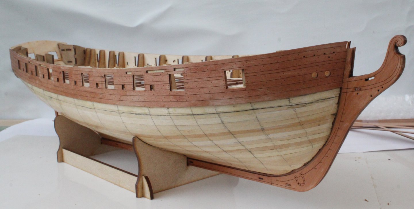
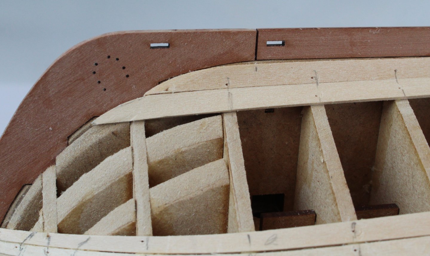
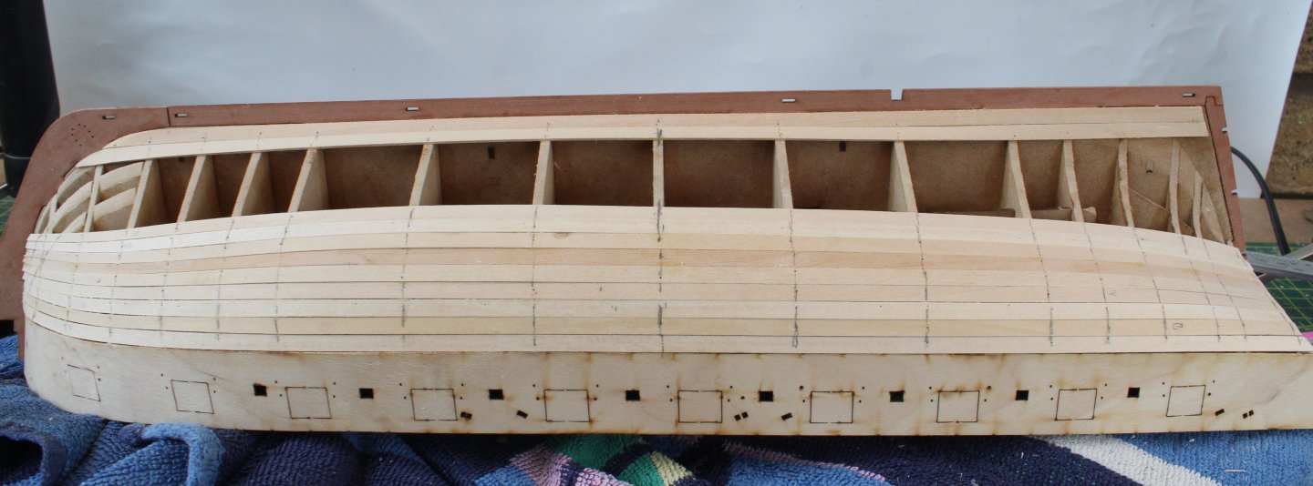
I have now completed the second planking on the left-hand side. As with the right-hand side I fitted planks of approx 140mmL. I also applied a lateral bend for the planks that were installed around the bow section. For the most part I am really pleased with how the second planking has turned out. The hull will now require sanding to iron out any bumps before I add the wales and copper tiles. In the final photo I am starting test fitting the parts I have made for adding the square tuck. There is a little bit more work required before they can be fitted. I also have to made the top right-hand square tuck frame part.


- 241 replies
-
- 12
-
-
- Vanguarrd Models
- Harpy
- (and 1 more)
-
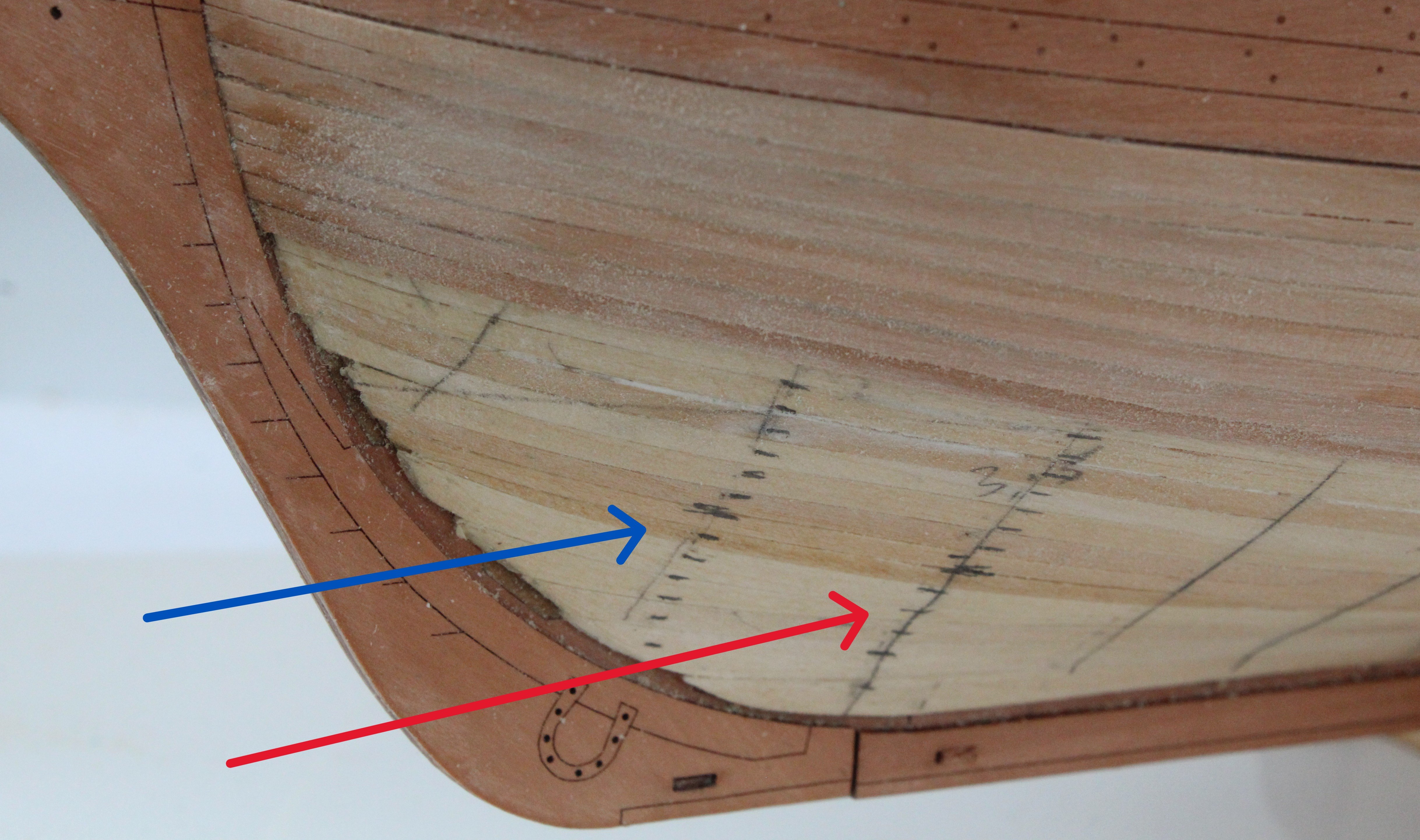
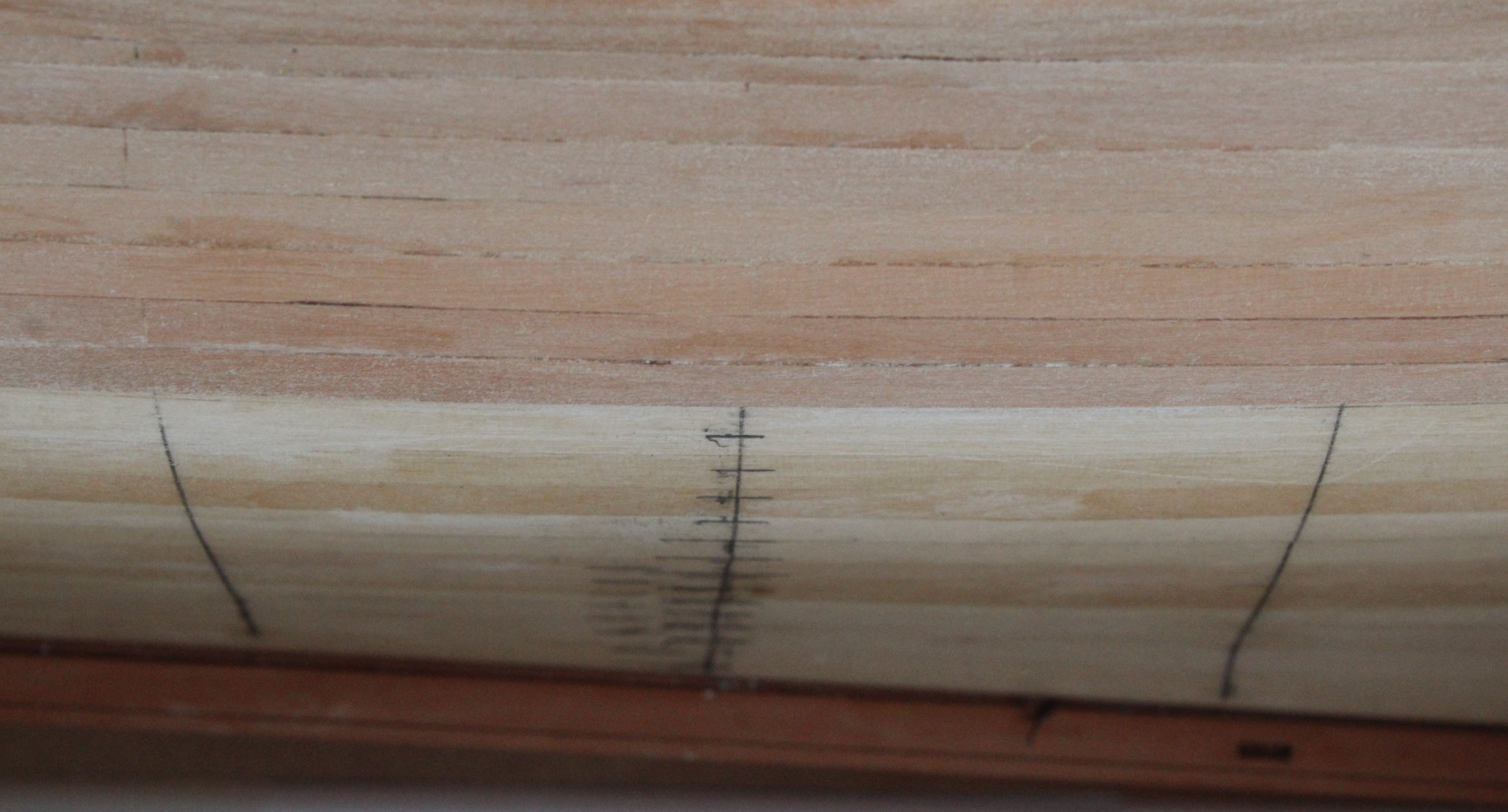
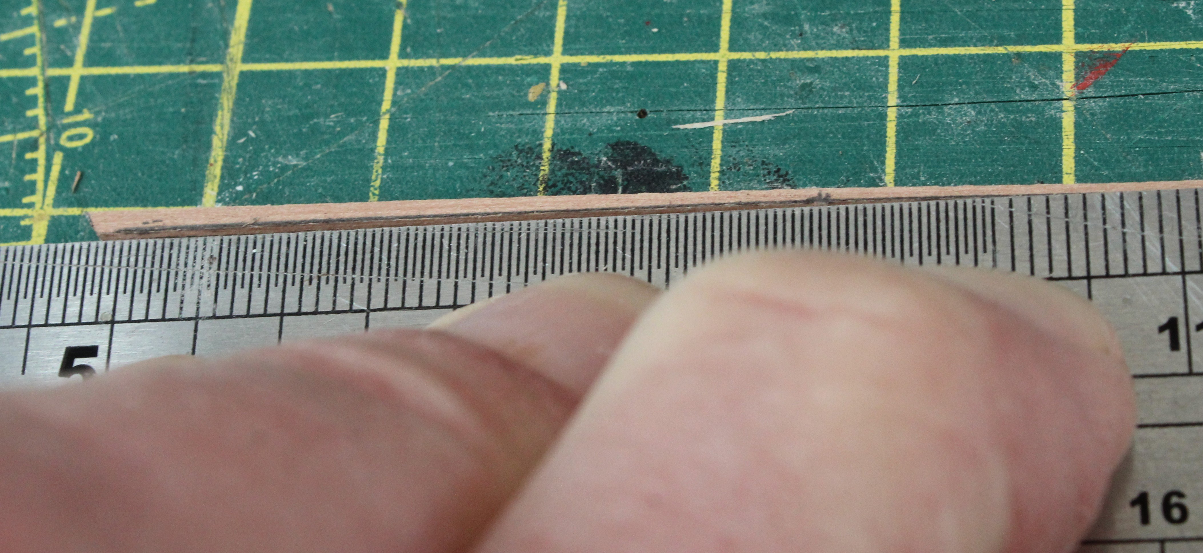
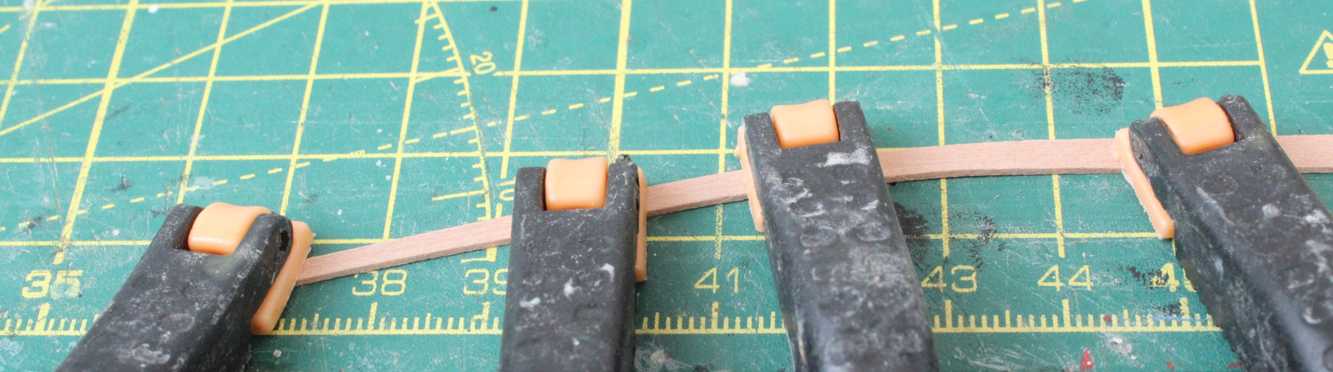
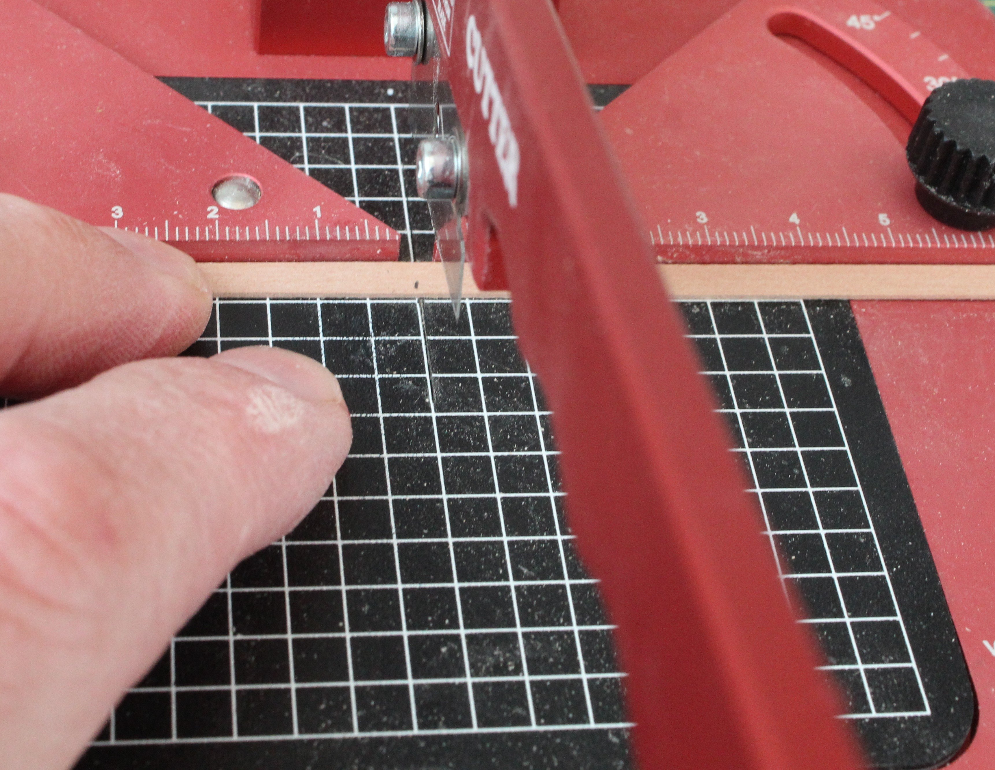
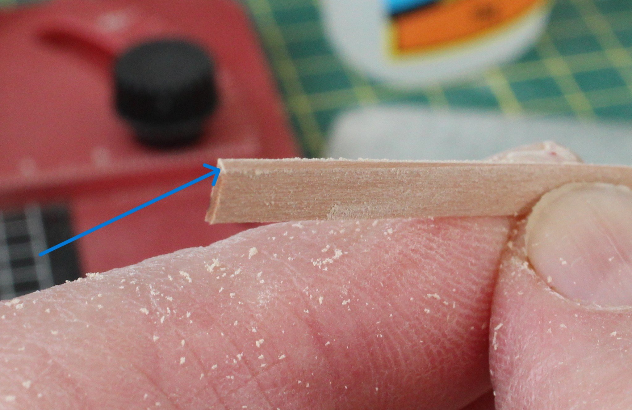
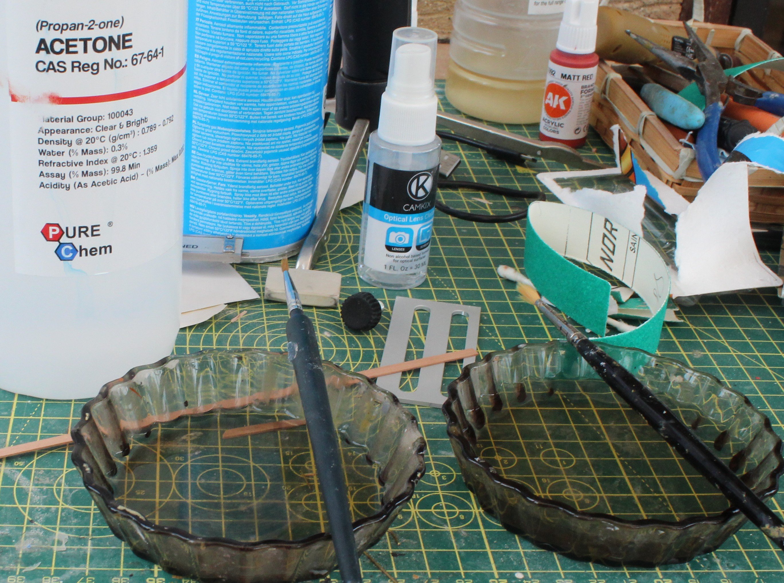
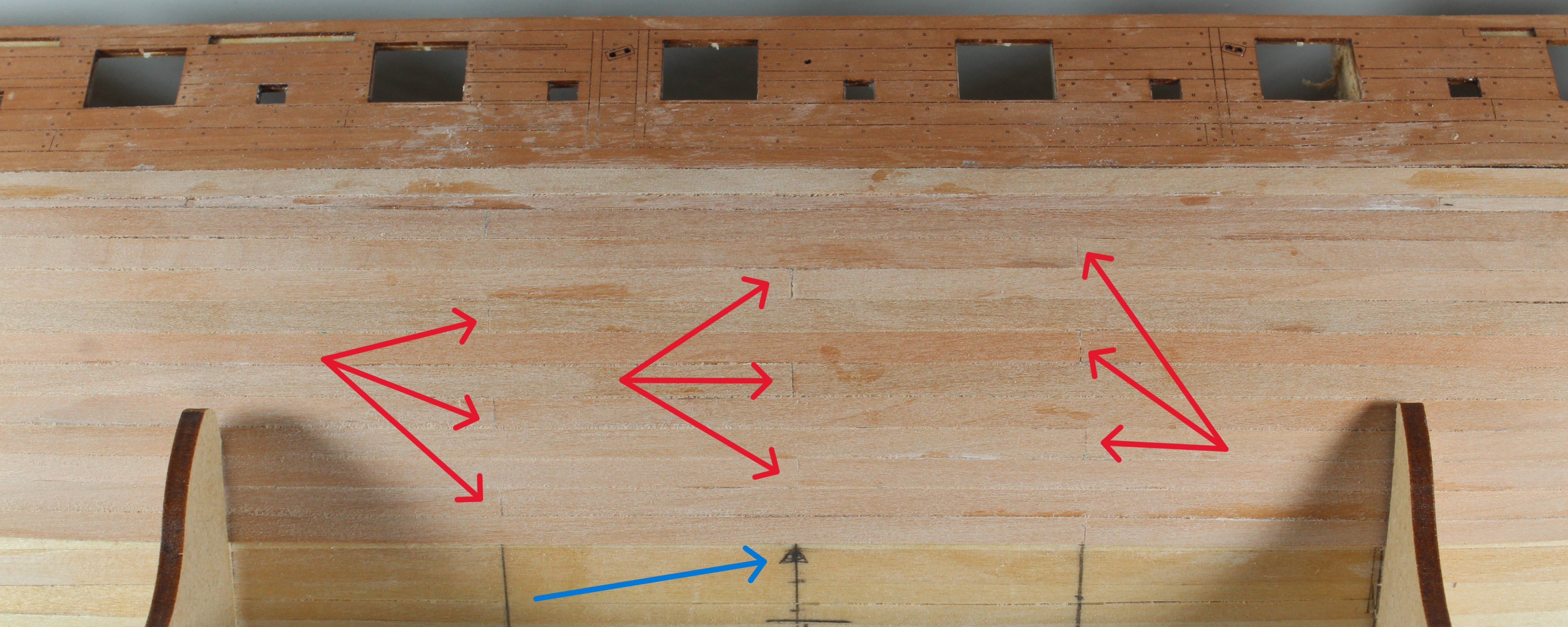
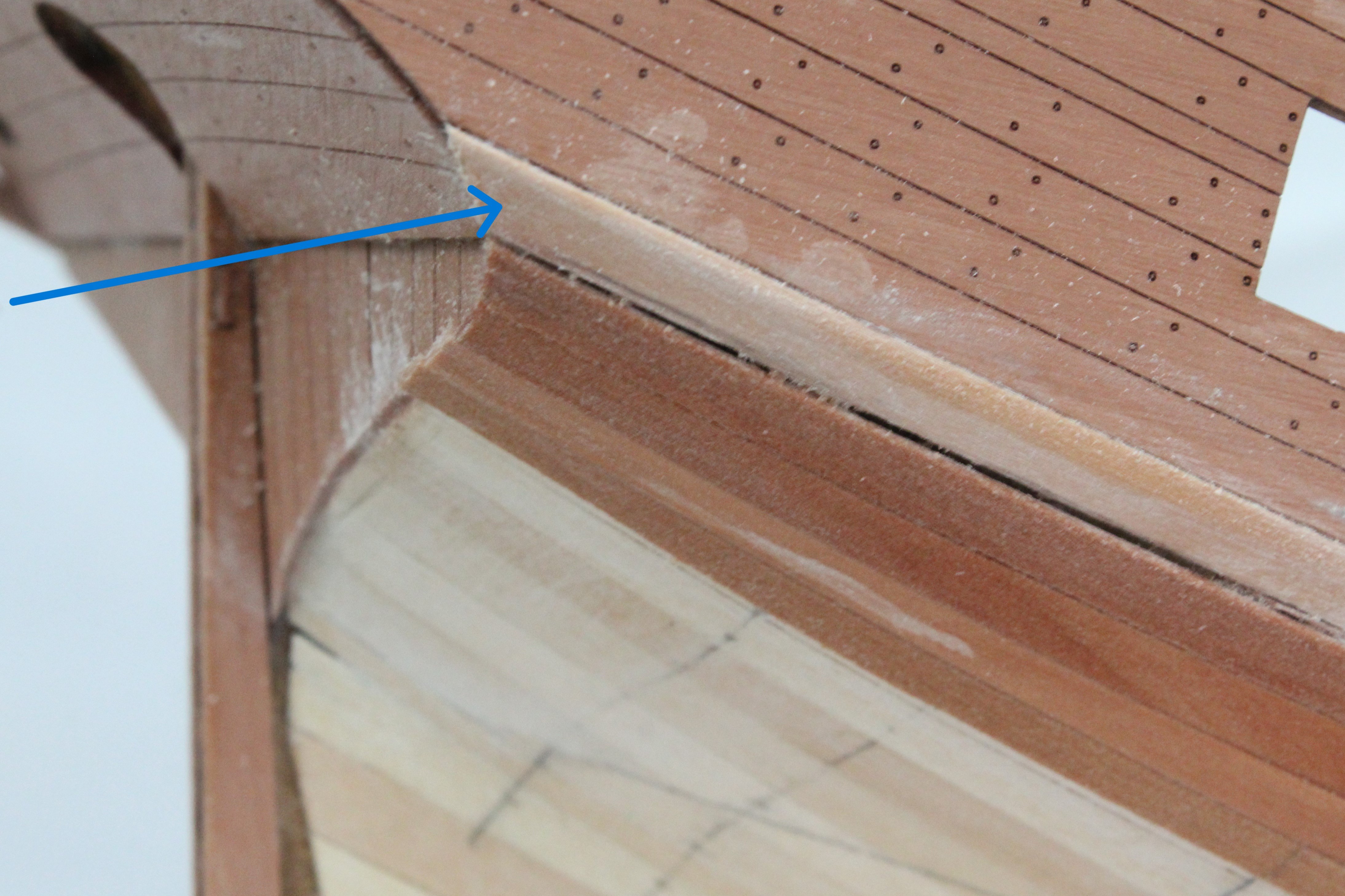
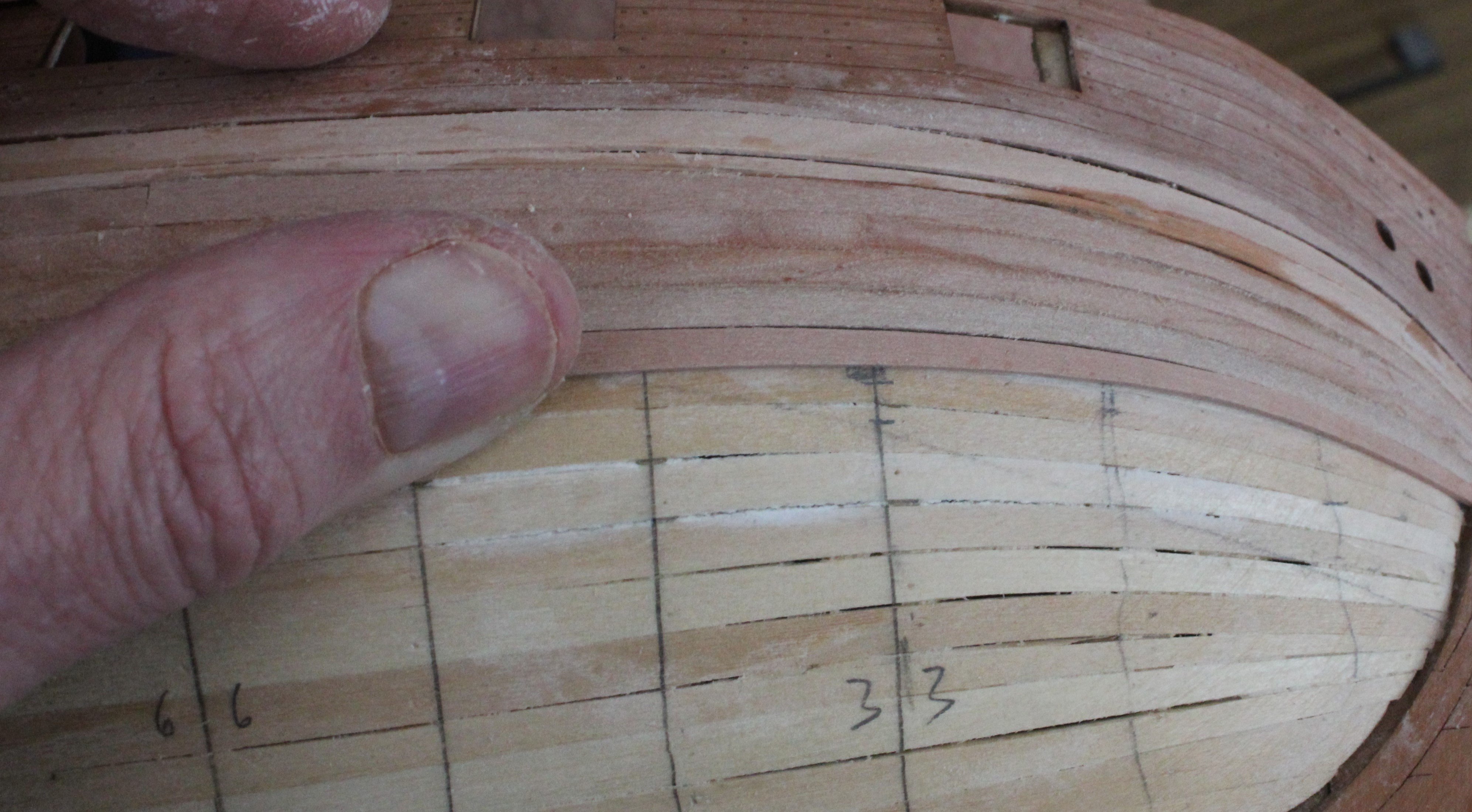
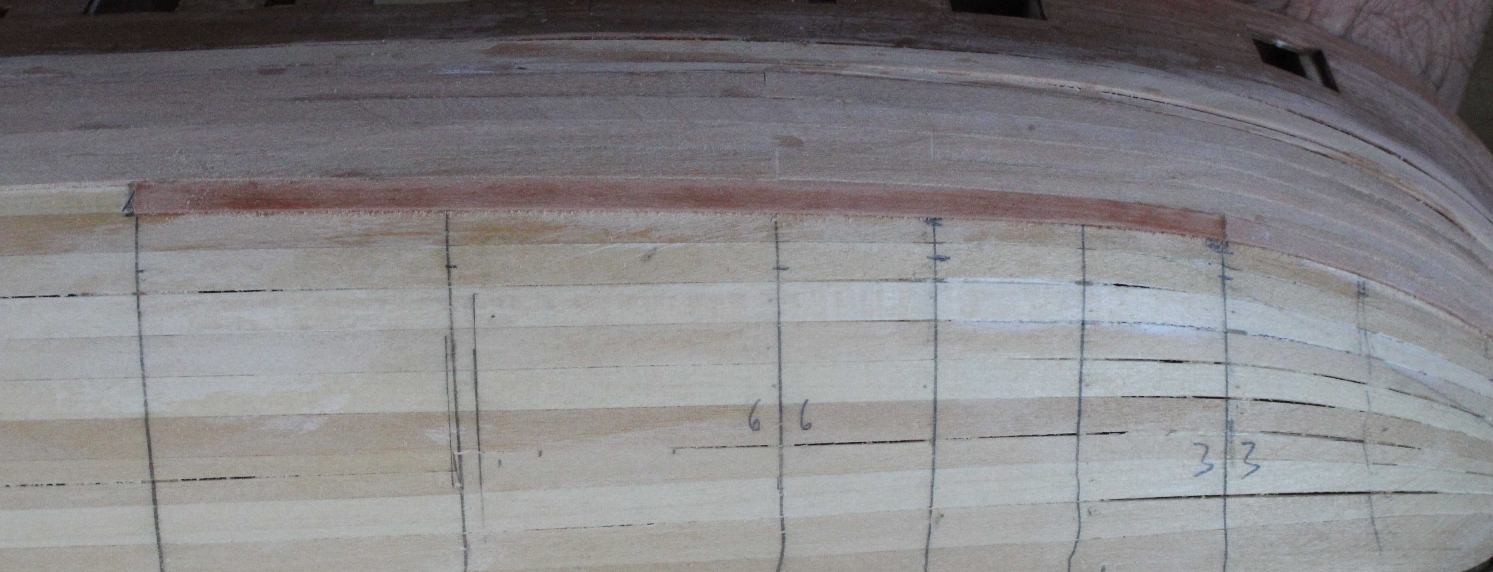
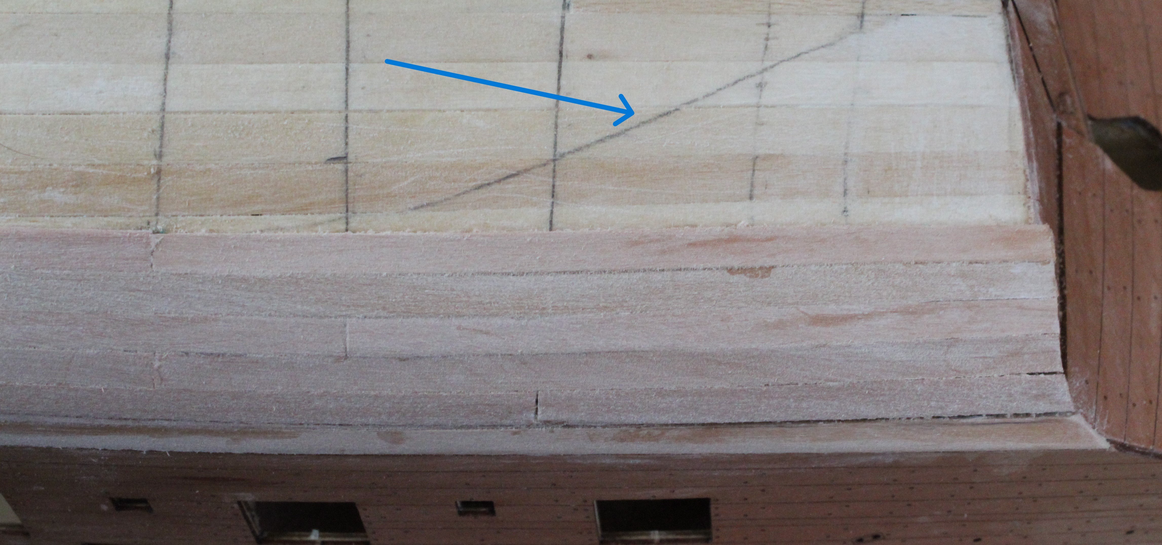
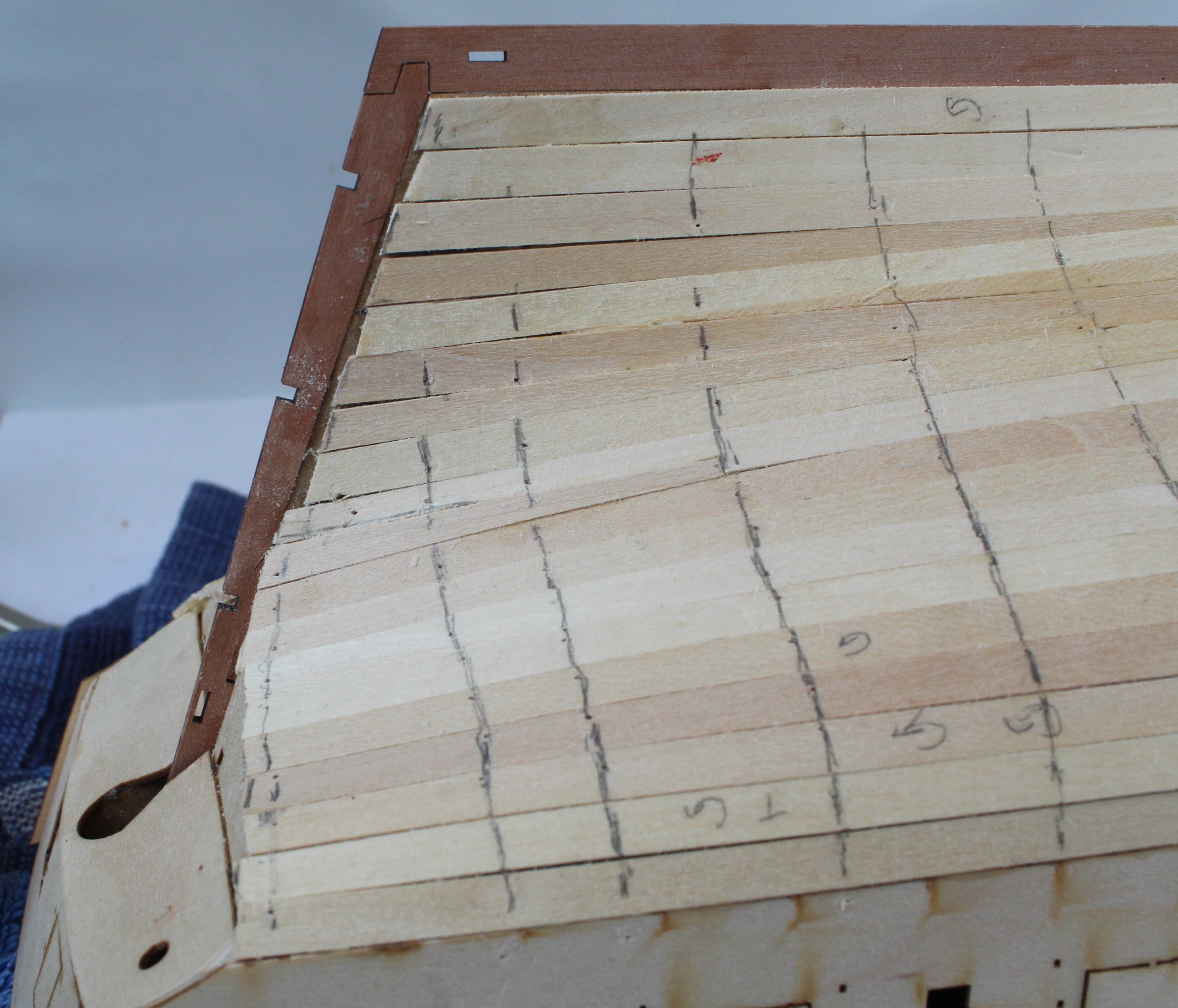
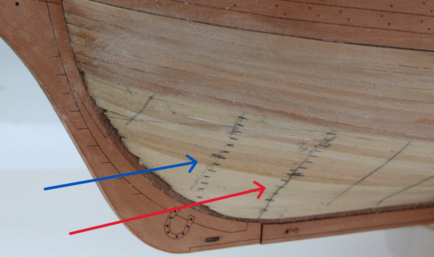
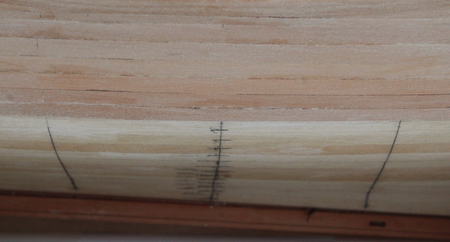
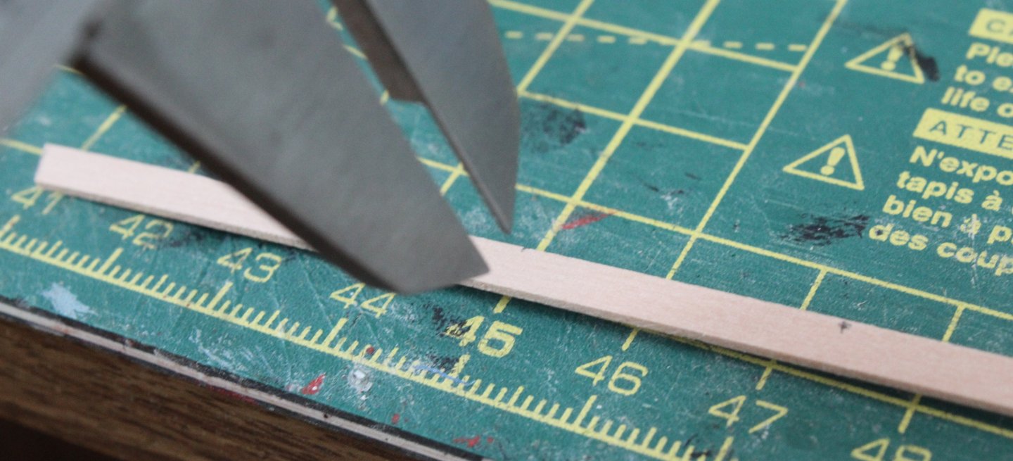
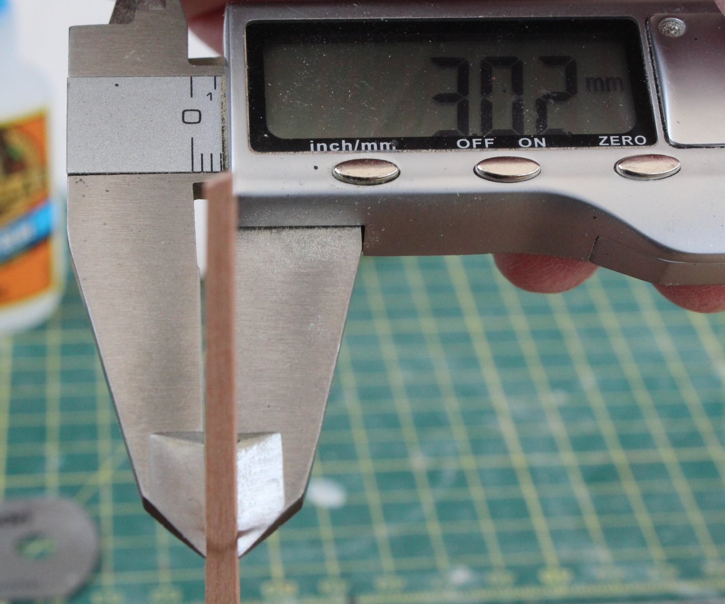
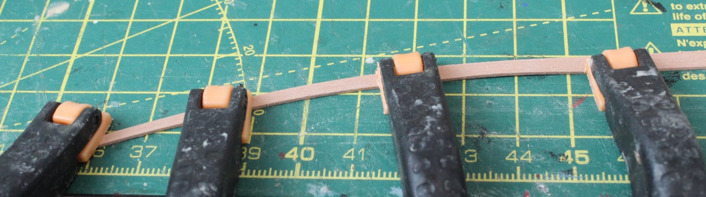
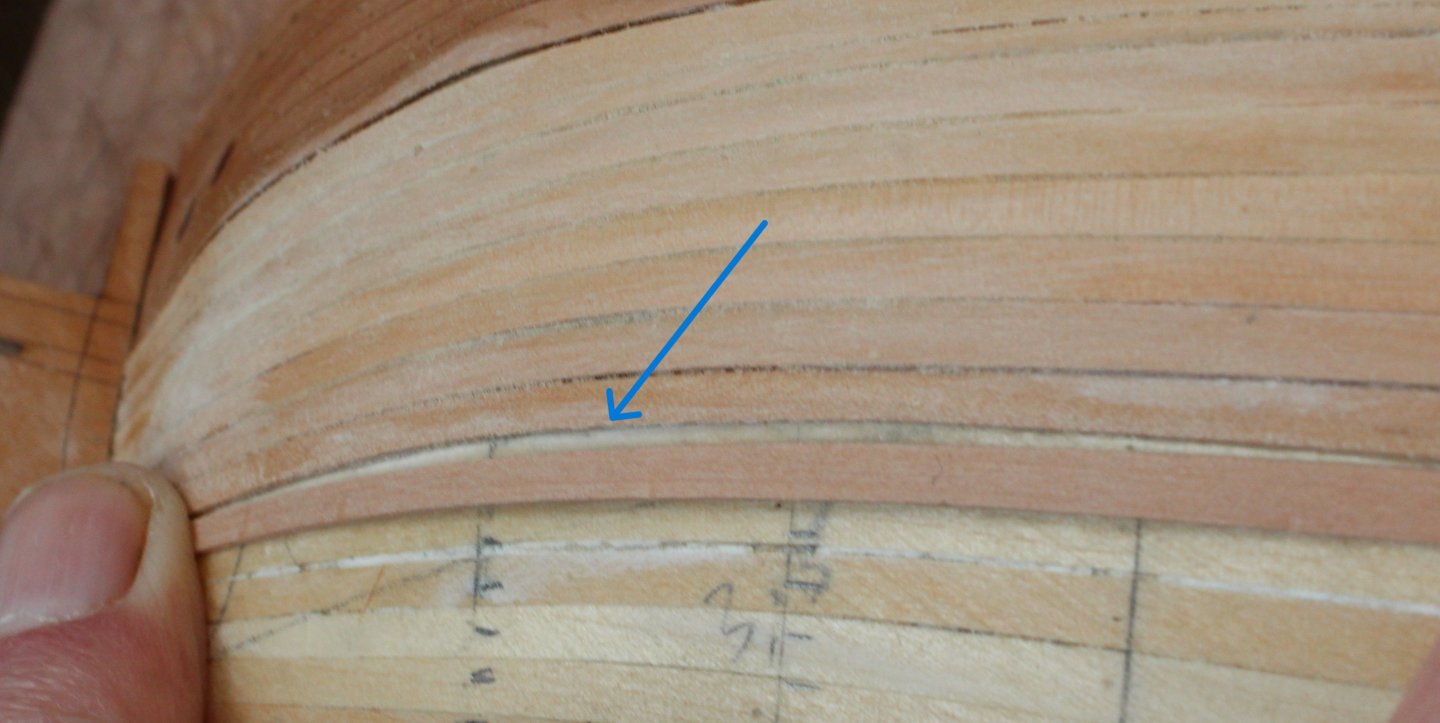
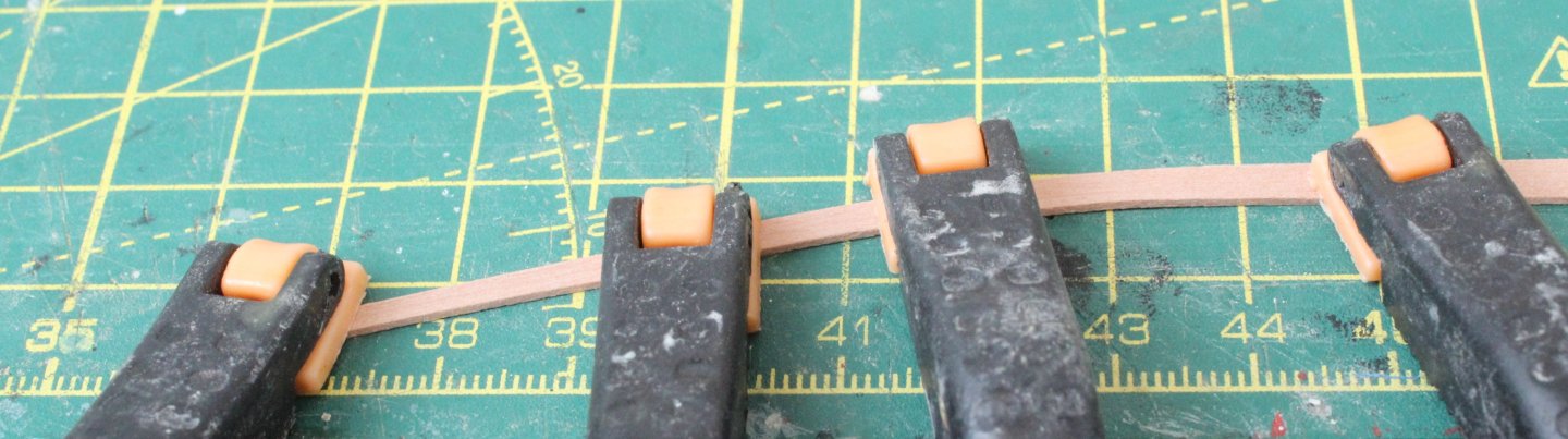
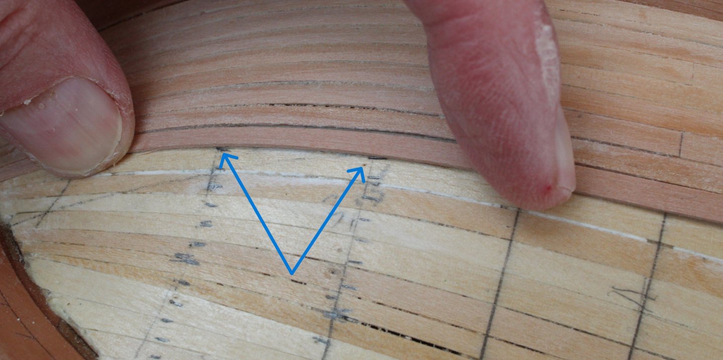
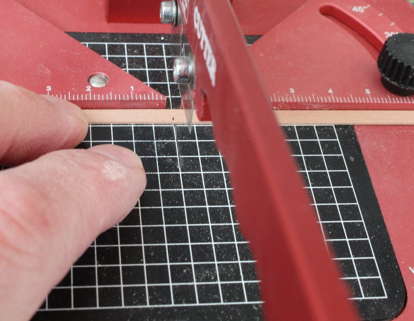
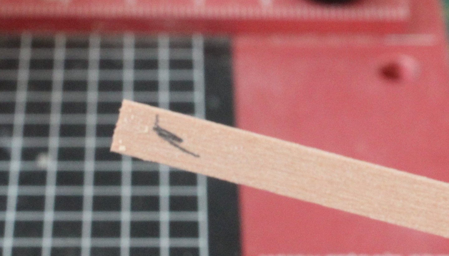
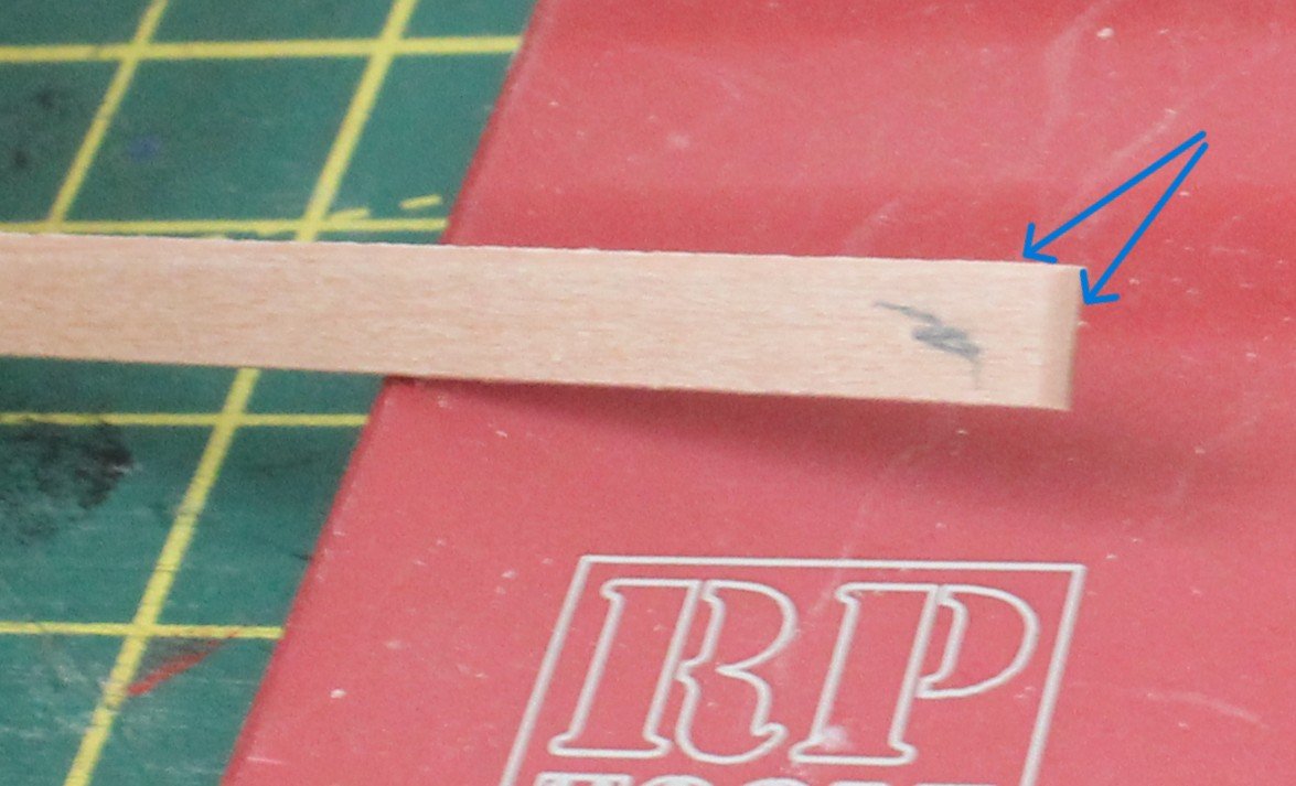
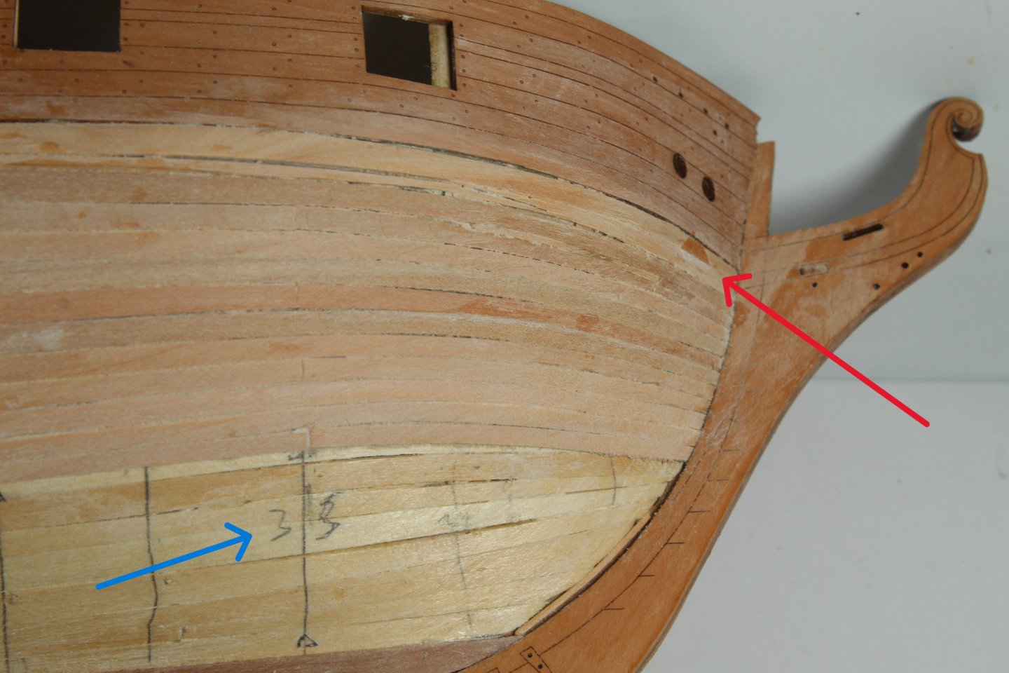
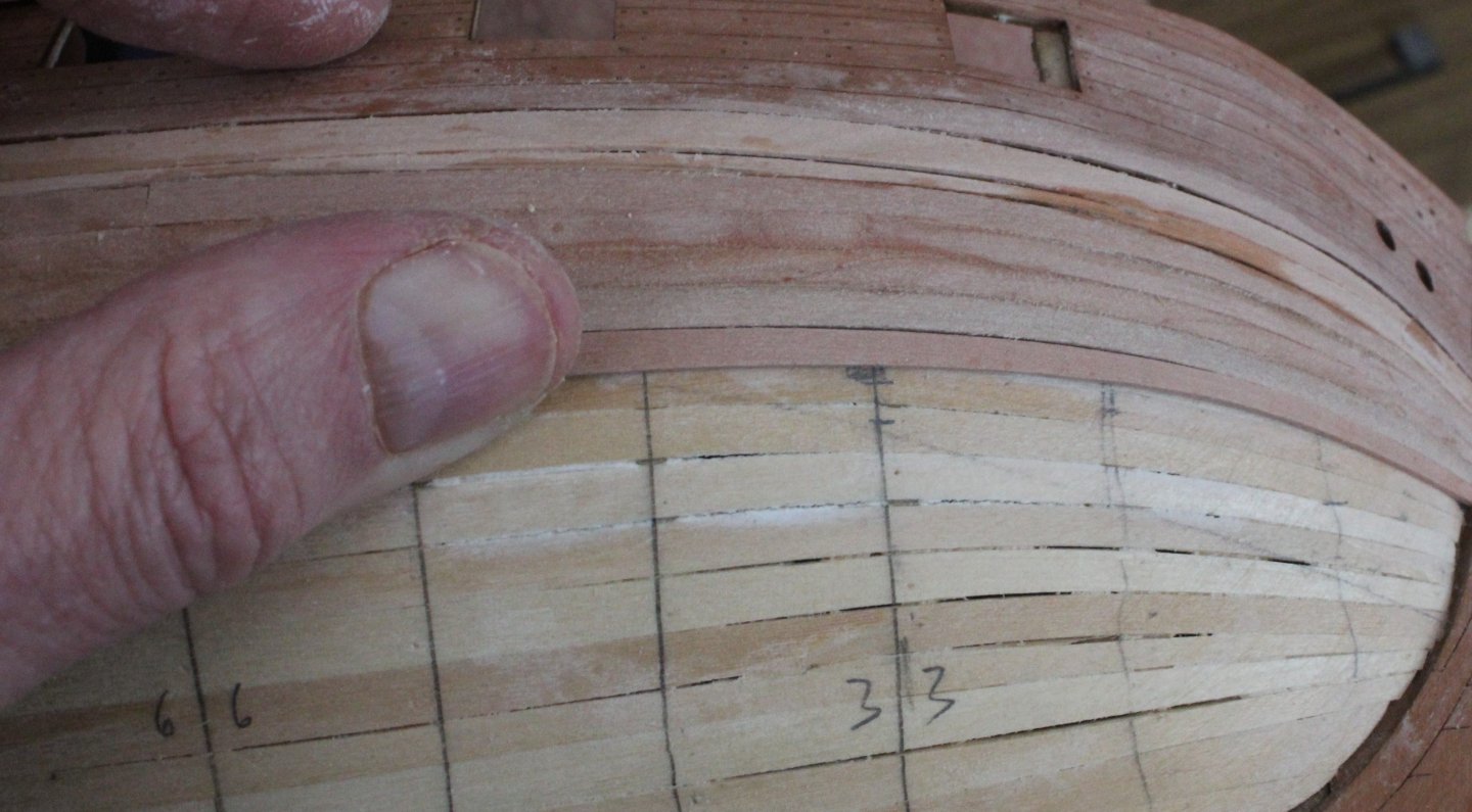
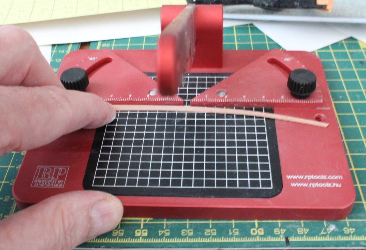
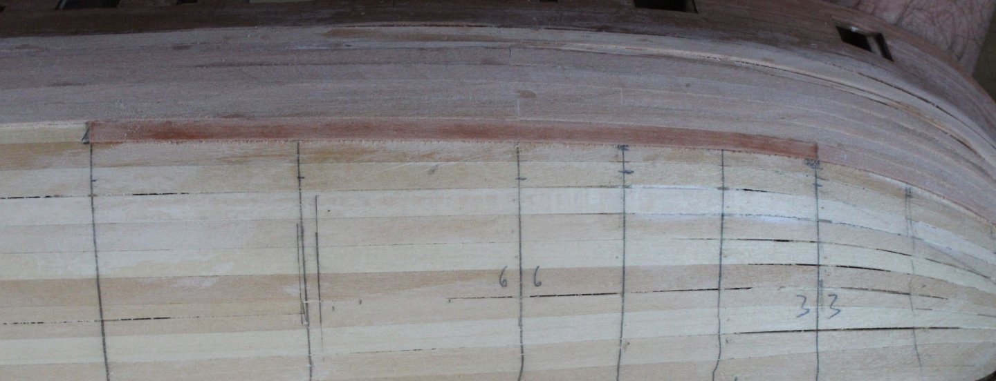
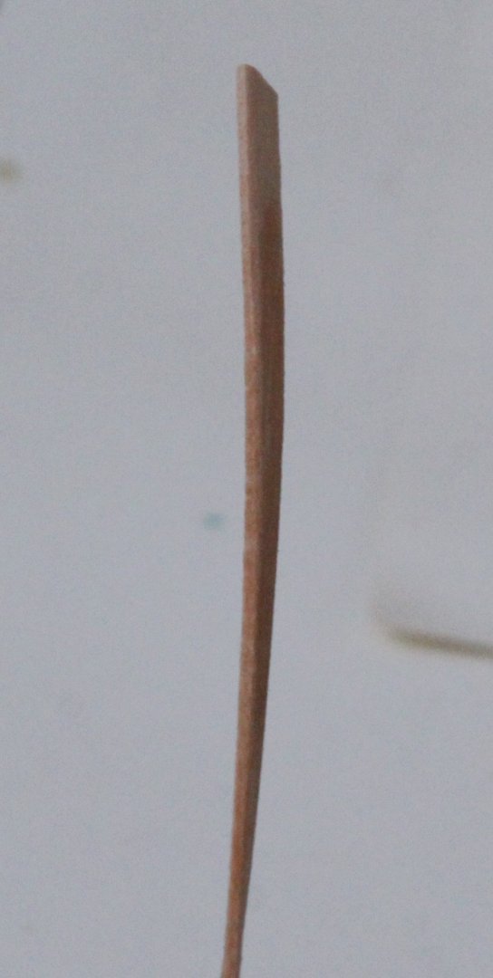
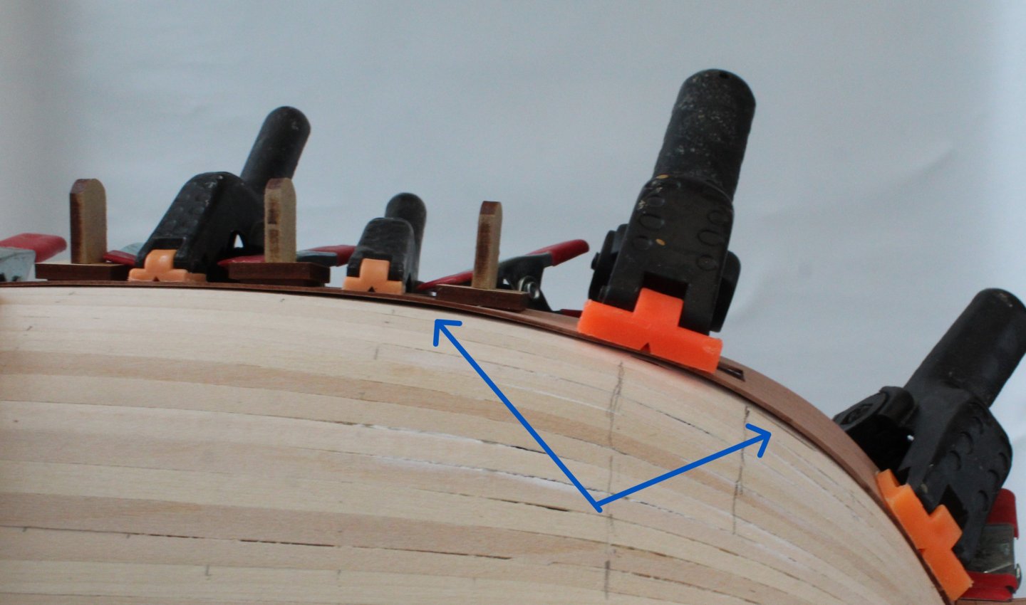
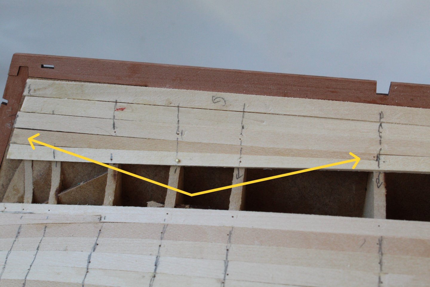
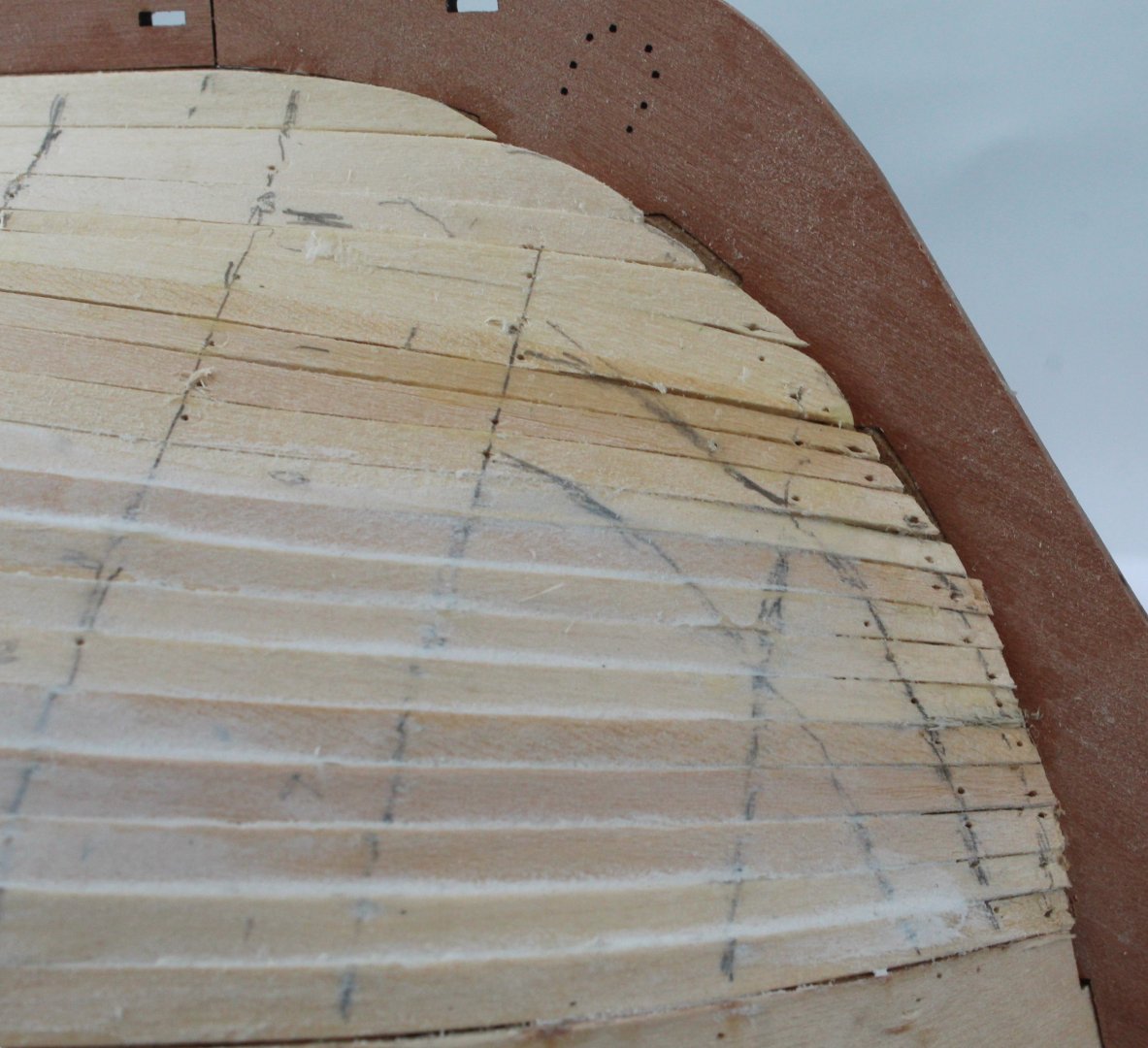
Planking on the left hand side has started and so far it is looking good. The first 6 strakes that sit beneath the wale have been added. I have added some marks to aid with the the plank tapering around the bow. In the first photo the blue arrow is where the planks are tapered to 3mmW and the red arrow indicate where the planks are tapered to 3.5mmW. The end of the plank which fits in the stem post is tapered to 2mmW. The final photo shows the planking terminating at the stern. The following set of photos, shows, in detail, the complete process I follow to fit a strake. Step 1 - Stem Post After making an initial angled cut the plank is placed in the rabbet and a pencil line is added so an accurate shape can be made. The plank is then removed and cut along the pencil line. Step 2- Marking the taper points With the plank held in place the 3mmW and 3.5mmW positions are marked on the plank. A 2mmW mark is also added to the stem post end and a mark for the end point for the taper is also added. Using the vernier caliper the taper points are then marked so a line can be drawn between all the marked points. Once the taper has been cut the plank width is checked using vernier calipers. Step 3 - Adding a lateral bend After the plank has been dipped in some water it is clamped so a lateral bend can be added. I used a hairdryer for approx. 1 minute to apply heat to the plank. The laterally bent plank is then test fitted, and as can be seen below, the plank is not a perfect fit. When this is the case the plank is then wetted again and the lateral bend is adjusted. It fits much better the second time around and also, as can be seen in the final photo below, the plank does followed the 3.5mmW and 3mmW marks. Step 4 - Fitting the Plank As I am fitting planks of approx.140mmL the position for the cut is made on the plank. The cut line repeats for every third strake. I used my guillotine to make the cut, and the reverse side of the cut plank is marked to ensure I can line up the cut edges when fitting the next plank. I apply a bevel to the top edge of the plank as this helps to keep the plank tight to the upper plank. I do have a couple of bowls on hand, one has clean water and one has some acetone to remove any excess ca glue. Ca glue is then added to the hull and the dampened plank is then added. Step 5 - Adding the remaining planks The next cut position is marked on the plank. Once the plank has been cut a bevel is added to both the top edge and also to the end which butts up to the previous plank. The dampened plank is then glued in place and any excess ca glue is wiped away. The process is then repeated for the final two planks. The final plank is then trimmed close to the lower stern counter pattern. It might seem a long winded process but it works well for me and is producing much better results. And it is not as time consuming as you might imagine once you get going.


- 241 replies
-
- 13
-
-

-
- Vanguarrd Models
- Harpy
- (and 1 more)
-
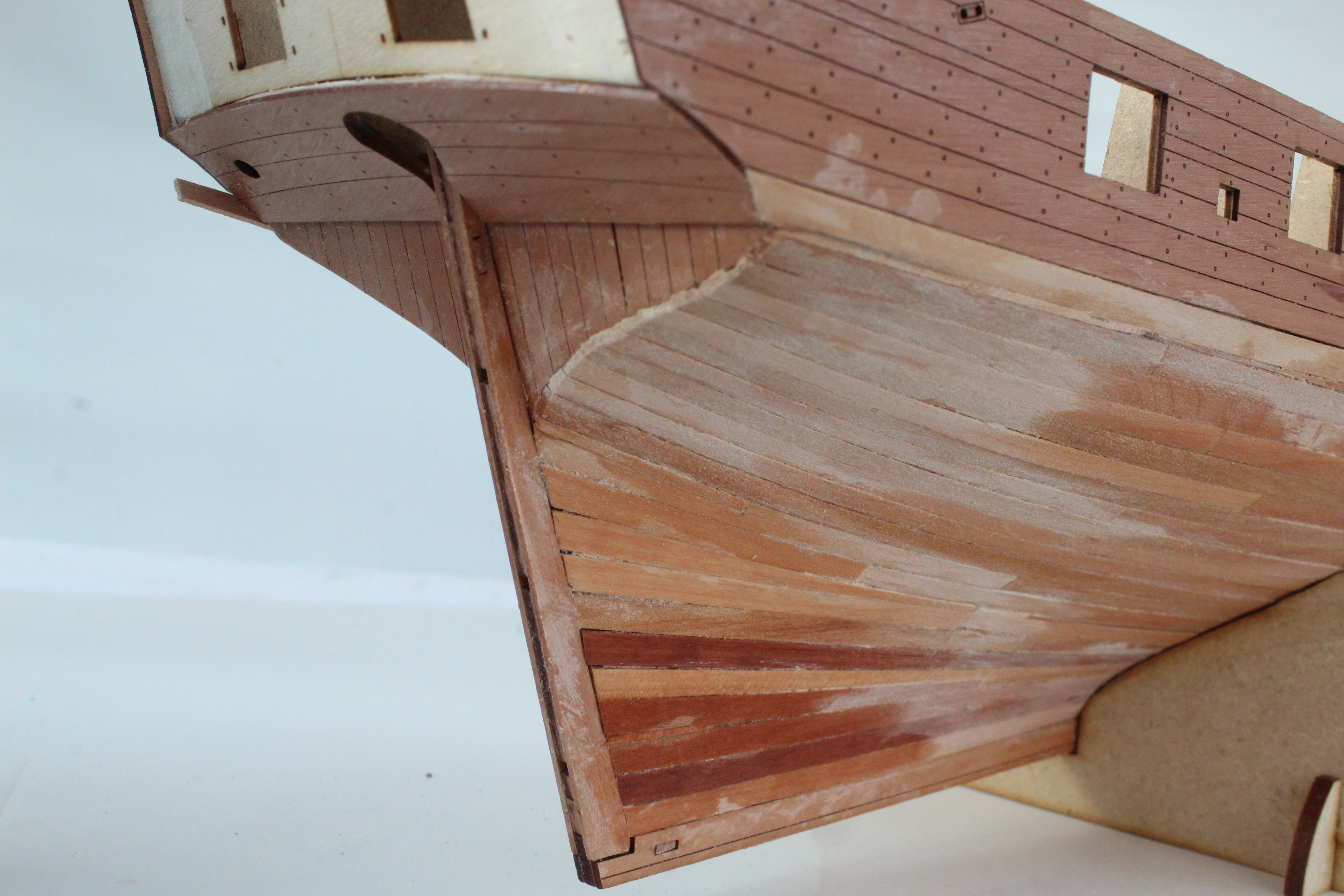
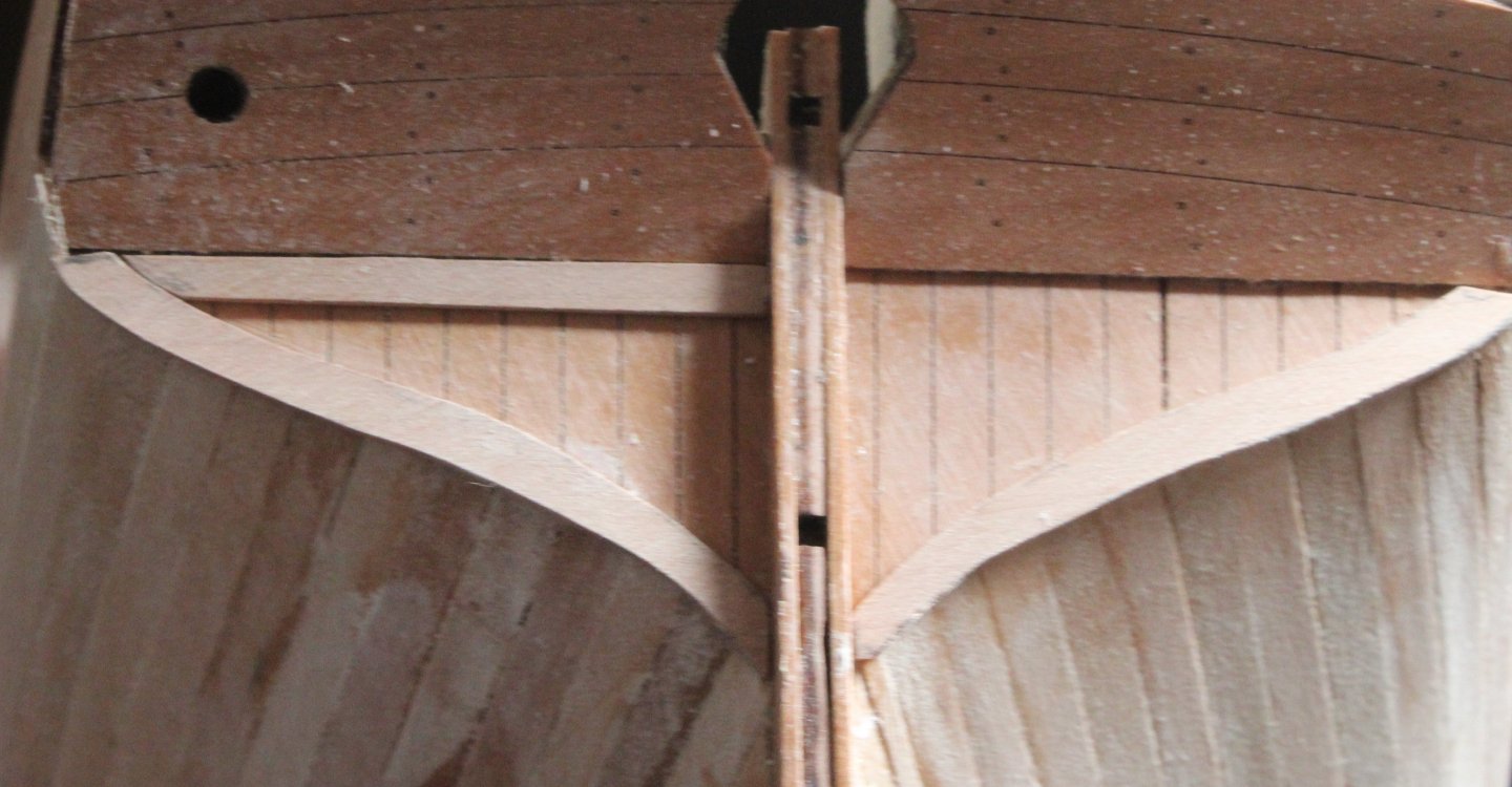
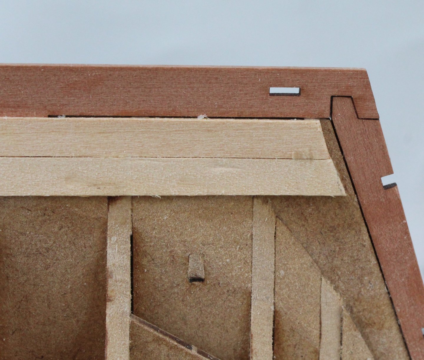
The square tuck arrangement is for framing so there are no open ends where the planking terminates at the stern.
- 241 replies
-
- 1
-
-
- Vanguarrd Models
- Harpy
- (and 1 more)
-
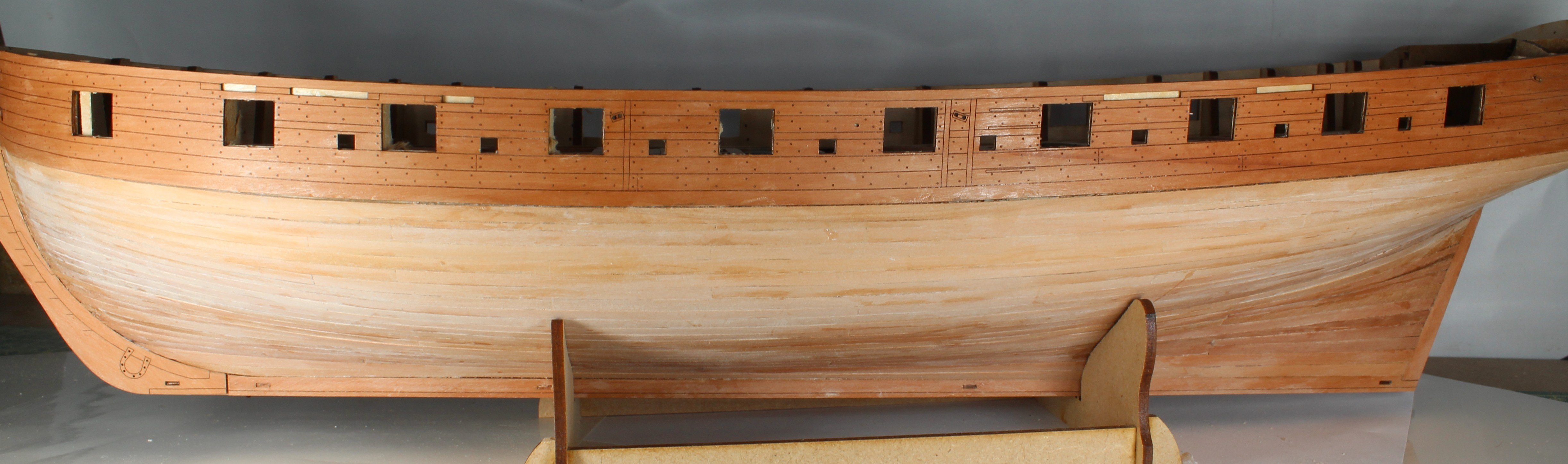
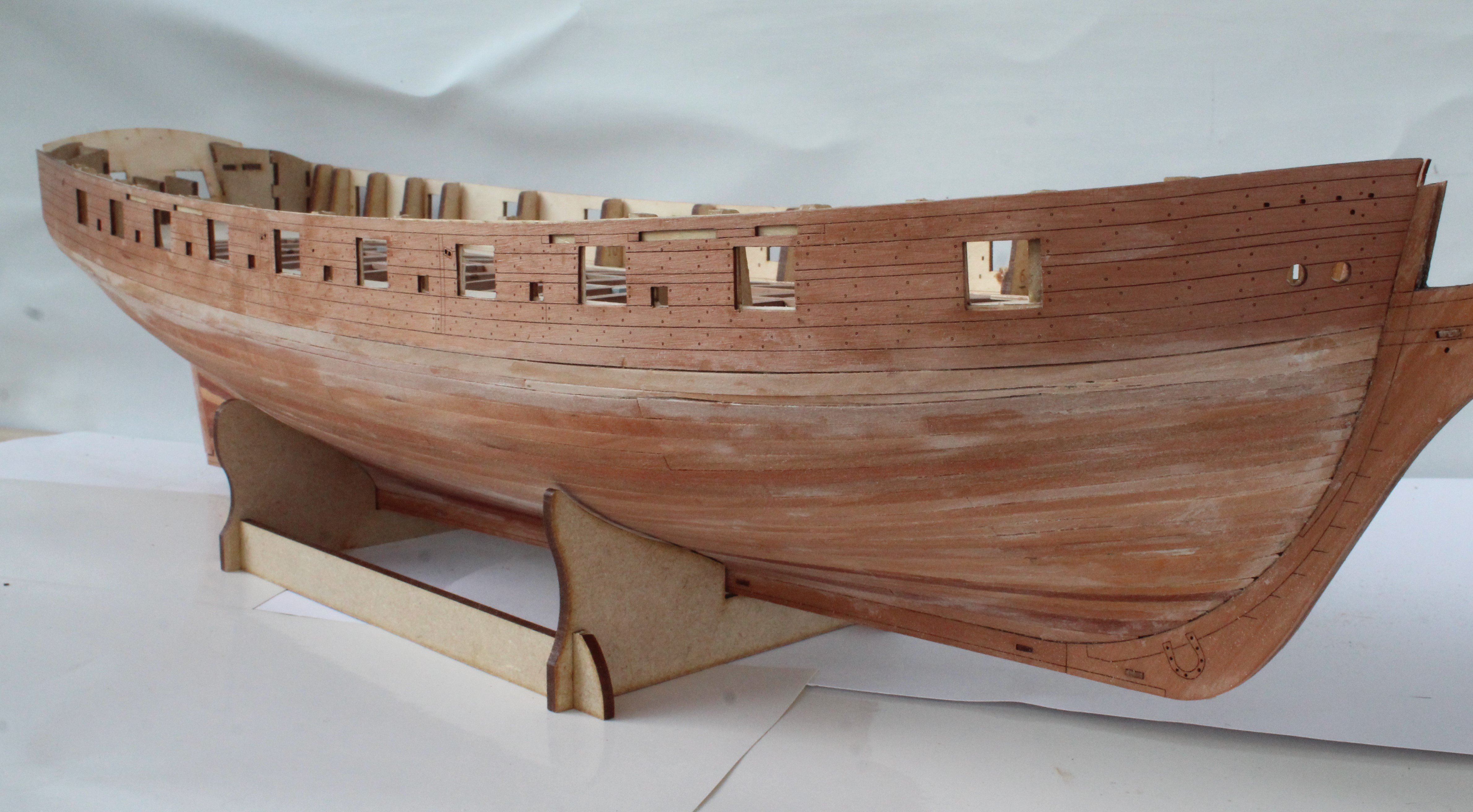
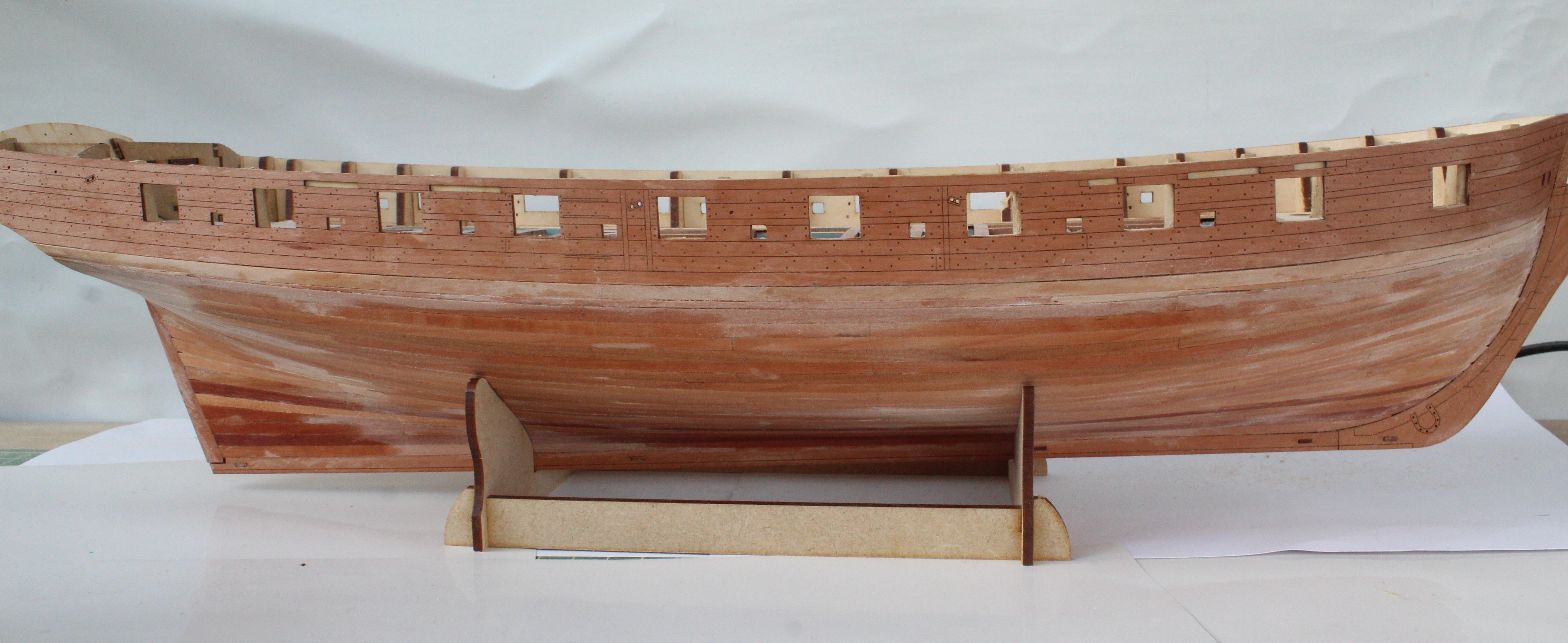
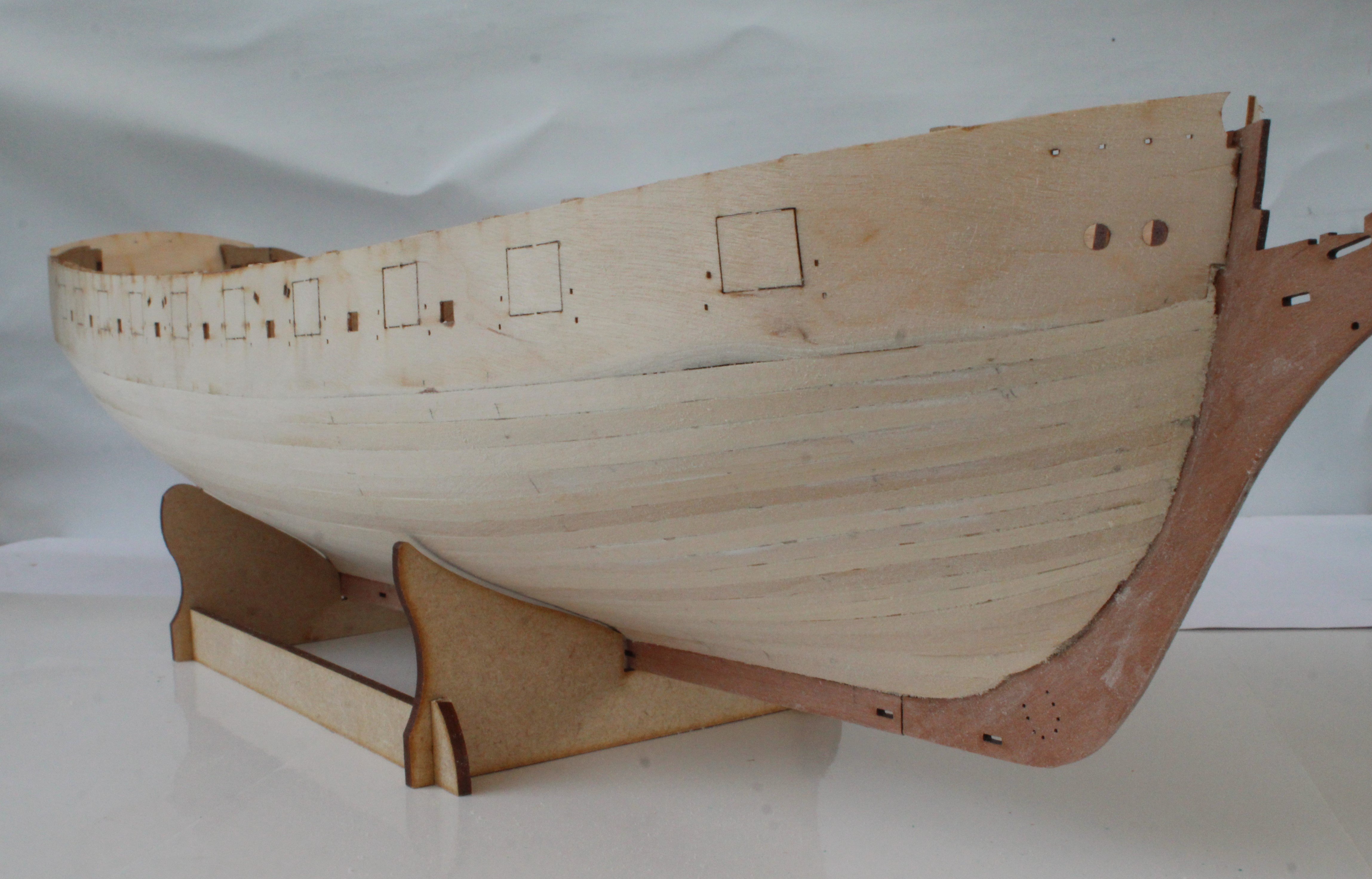
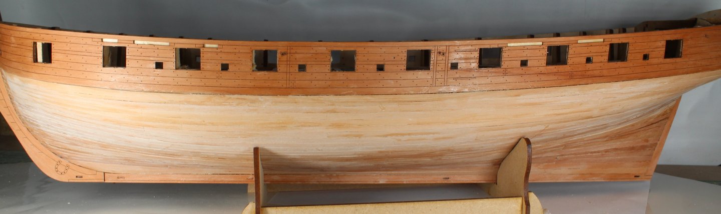
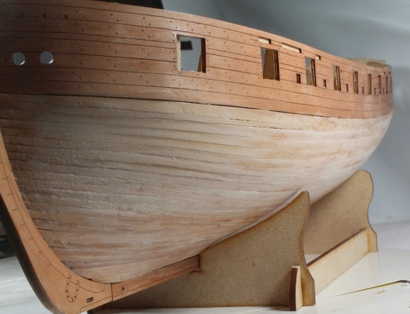
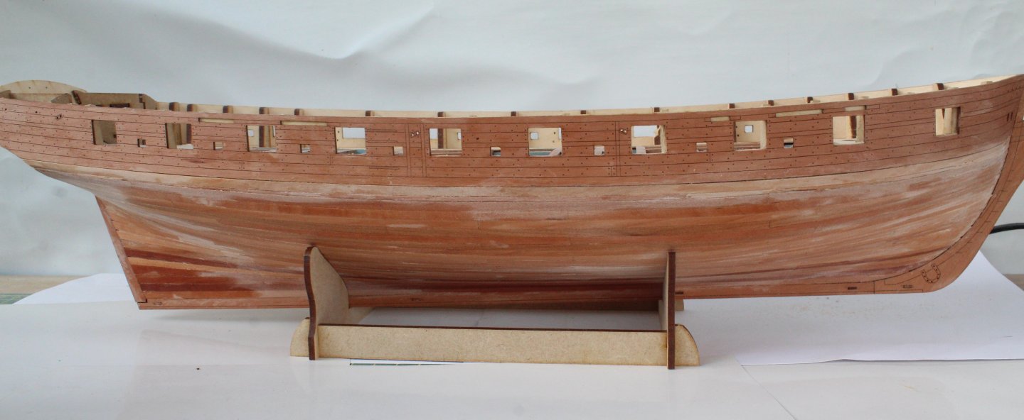
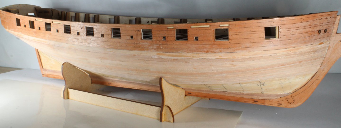
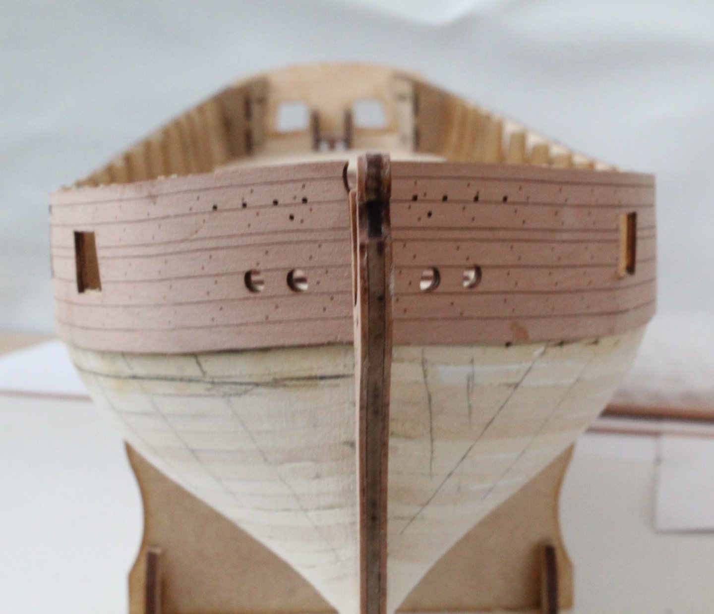
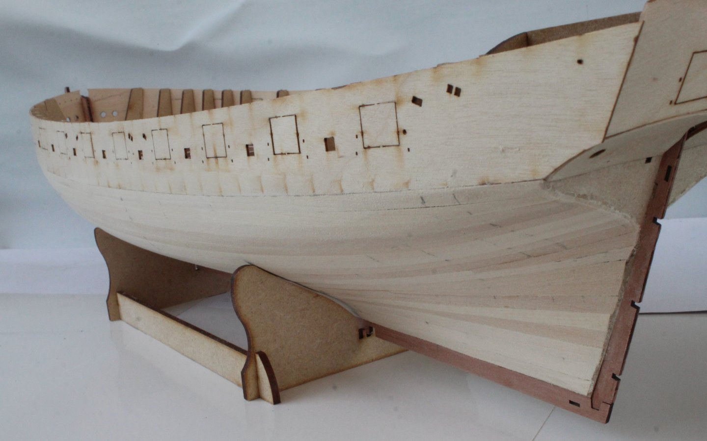
I have now completed the right-hand side second planking. There is a wet nature in the photos below as I did brush the hull with a dampened brush. This was done to remove any unwanted dust from the hull and to also highlight any areas which may require a little bit of attention. Overall I am very satisfied with how this has turned out, it is not perfect but generally it looks good to the naked eye. I will now spend a few more days repeating the process for the left-hand side. Fingers crossed I can repeat what I have done already. The wale (when fitted) will positioned between the lower laser etched line on the bulwark pattern and the third strake. I am planning to add a square tuck to the stern.


- 241 replies
-
- 16
-
-
- Vanguarrd Models
- Harpy
- (and 1 more)
-
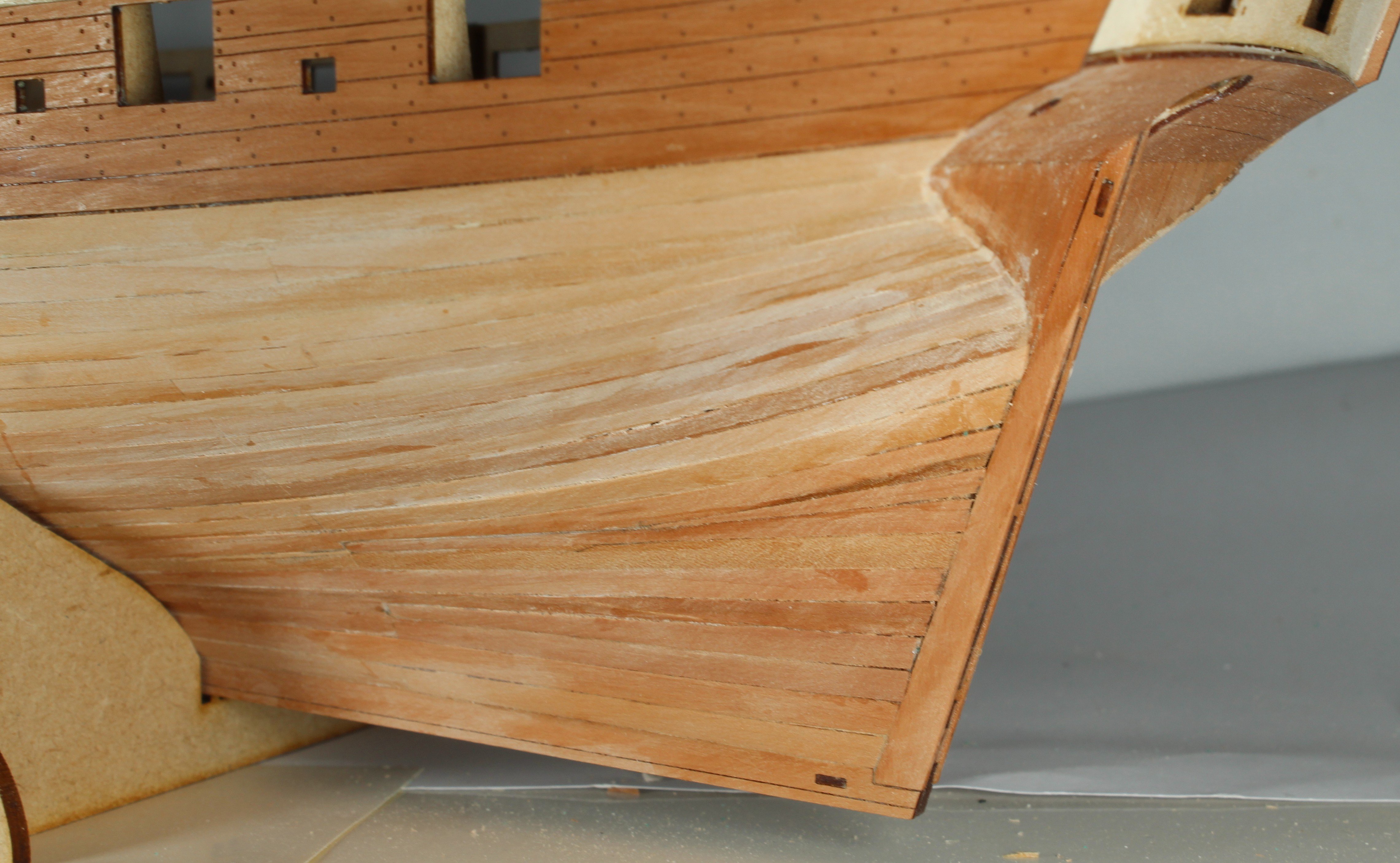
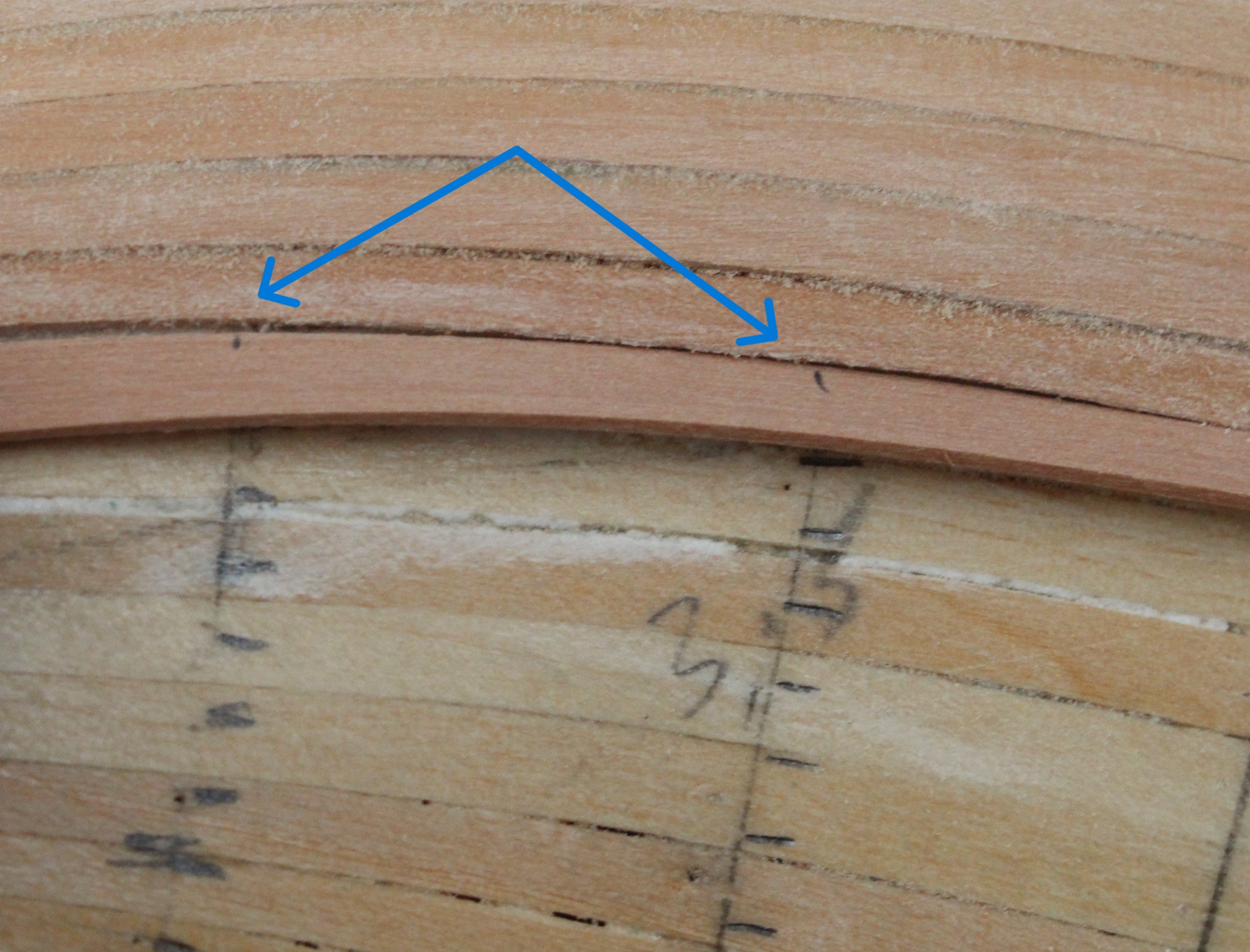
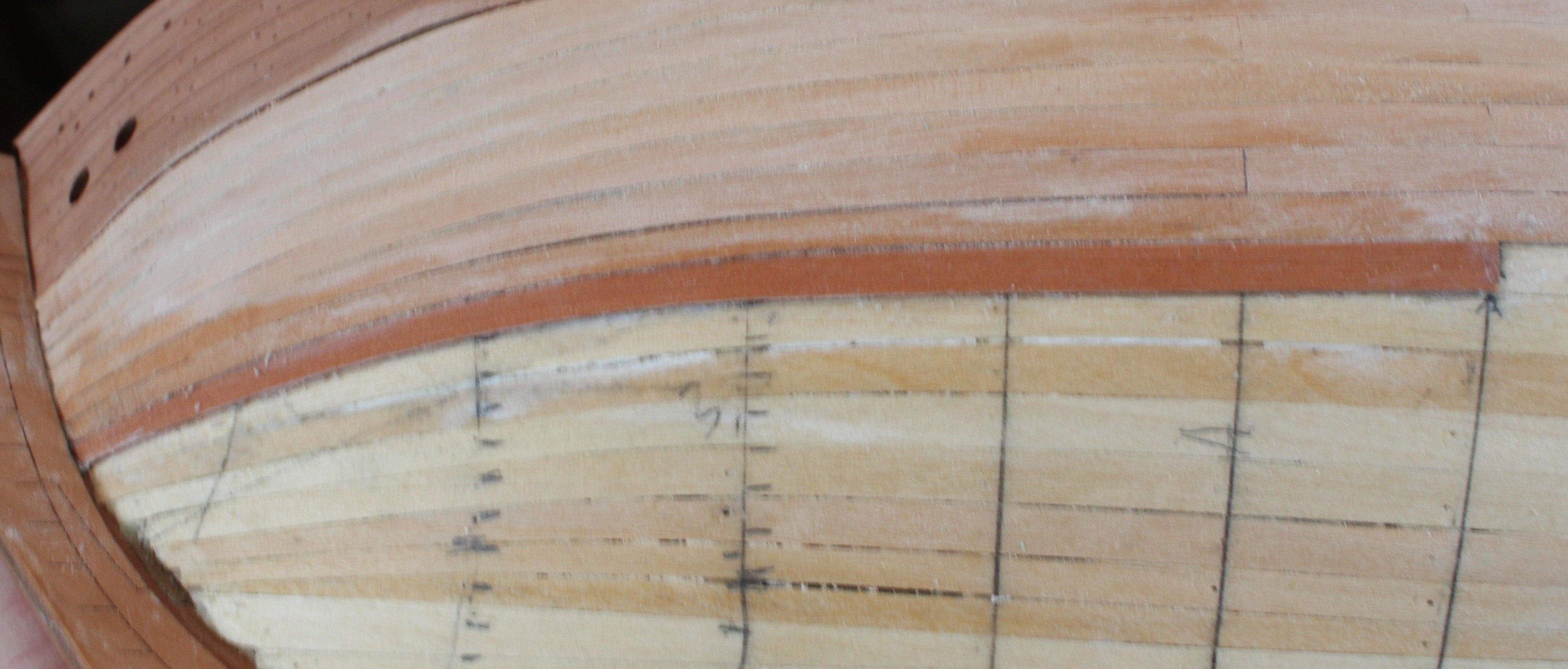
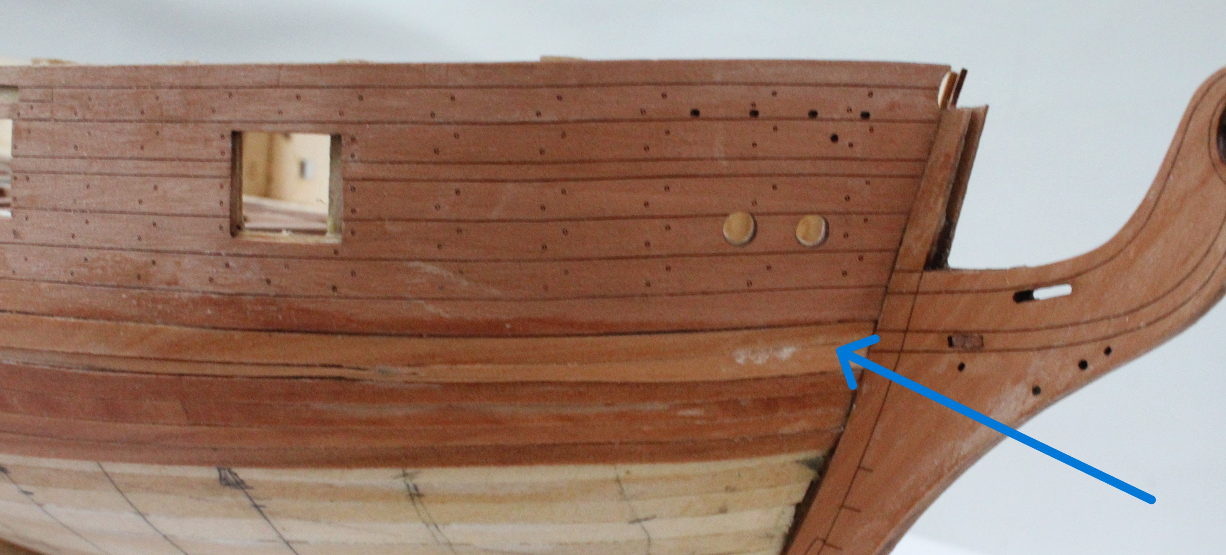
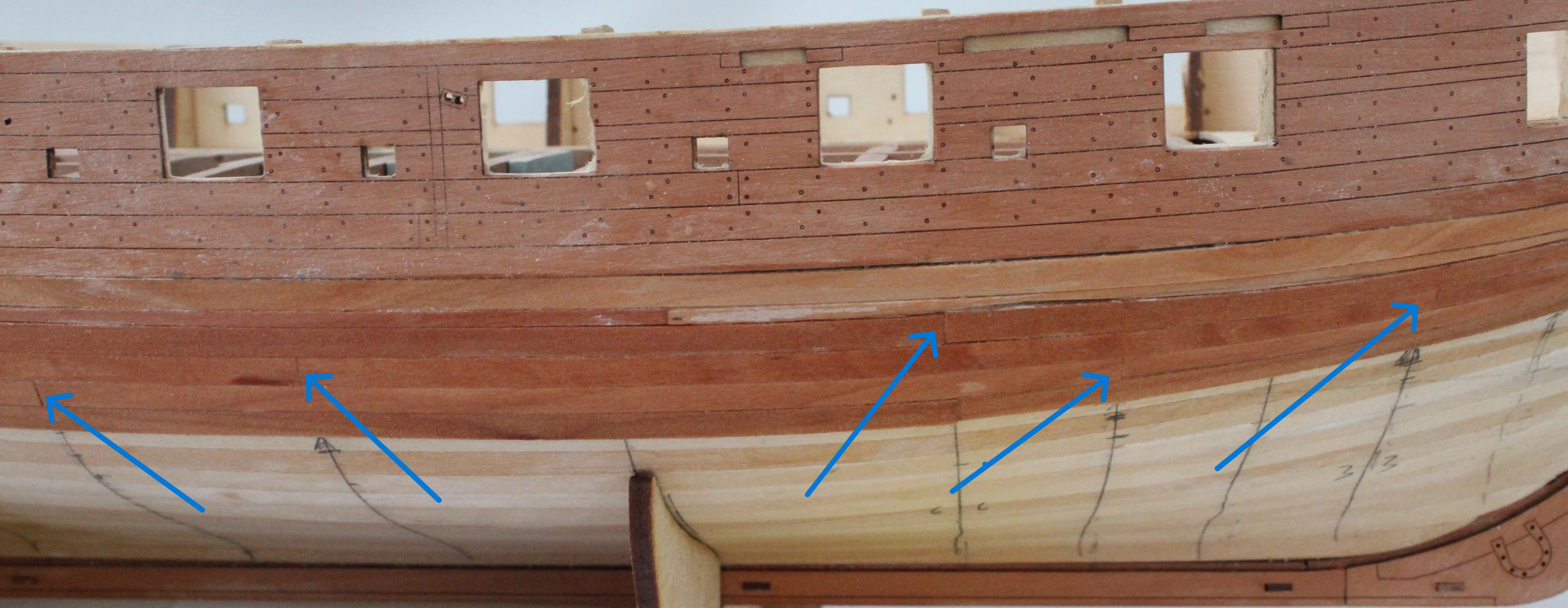
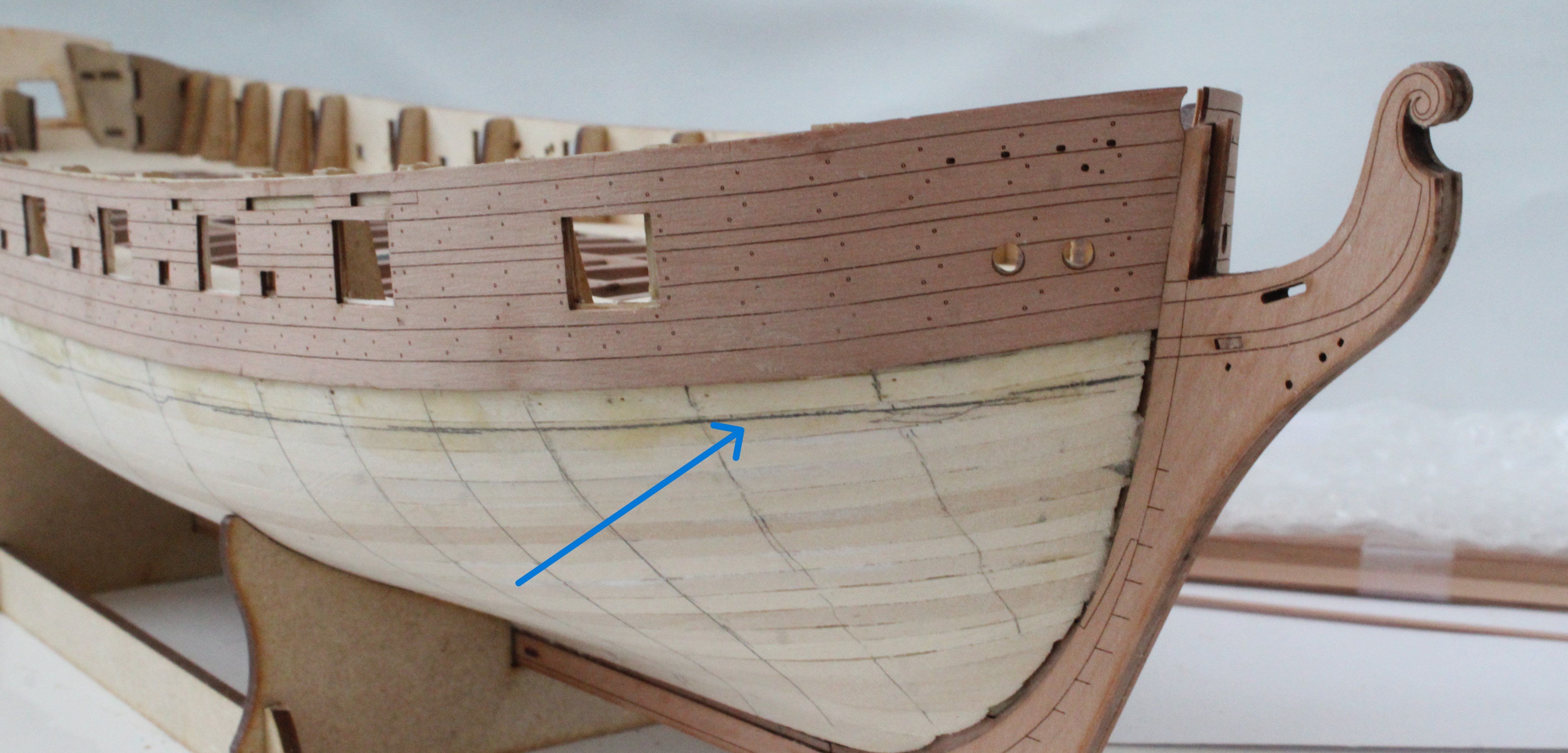
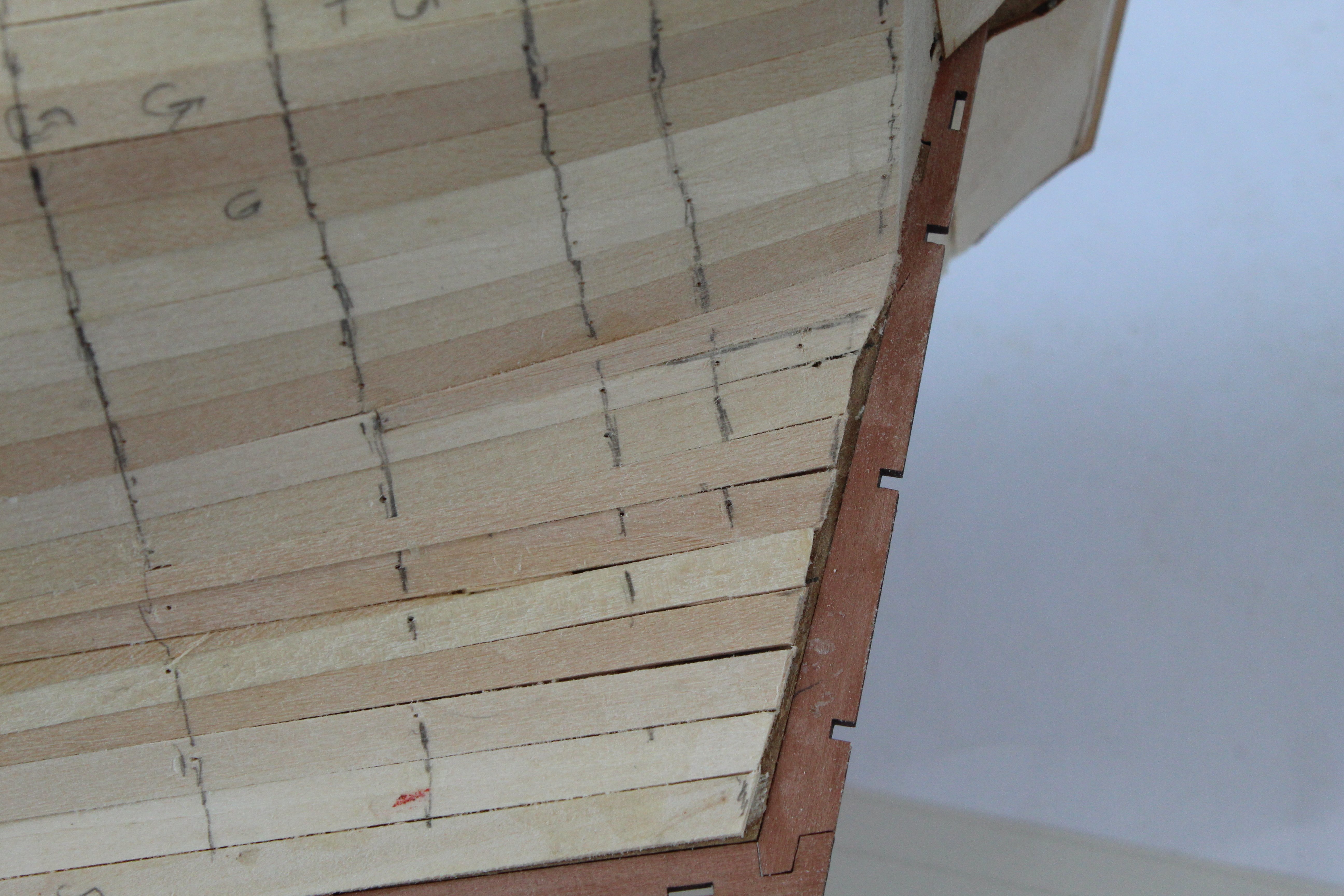
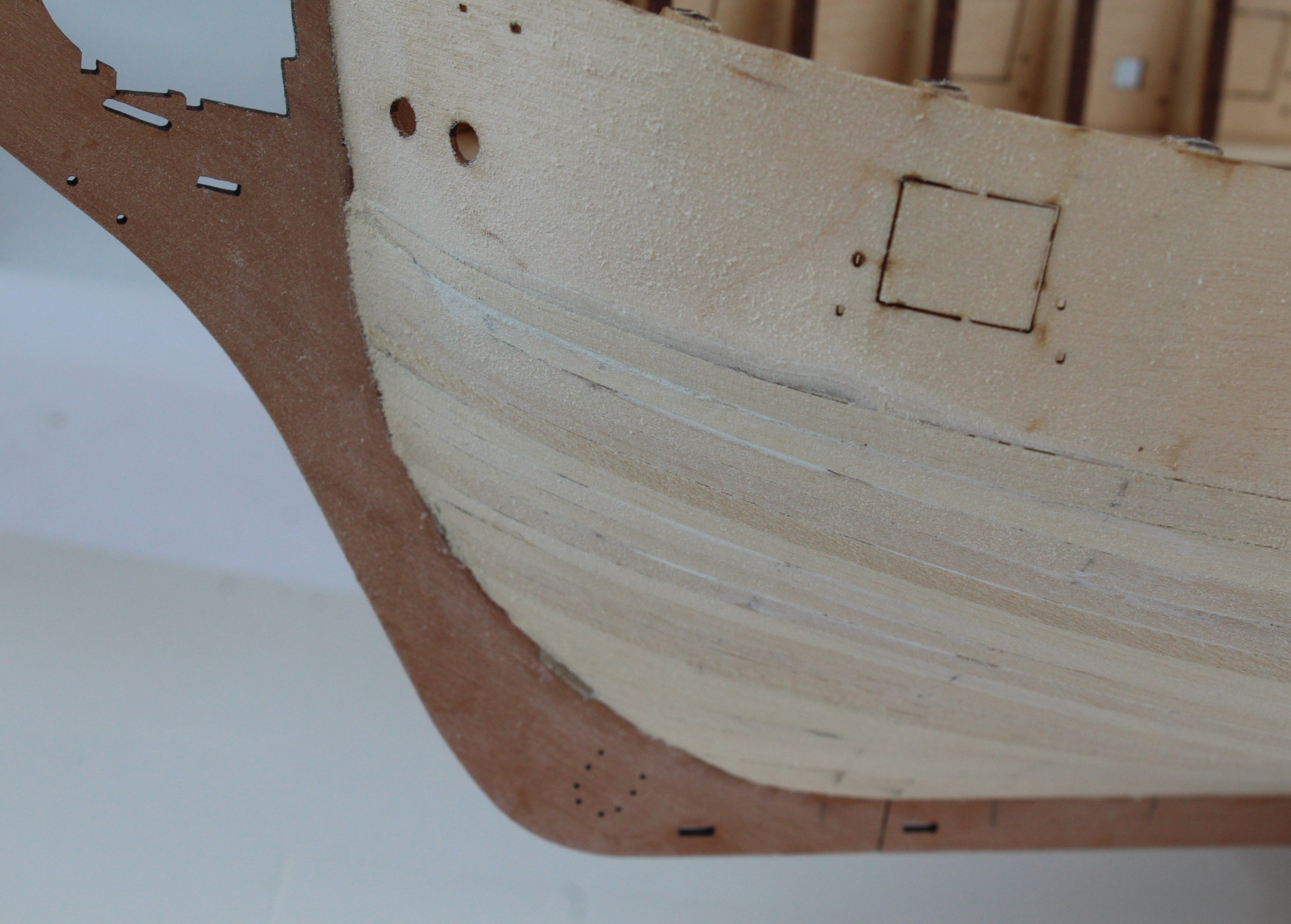
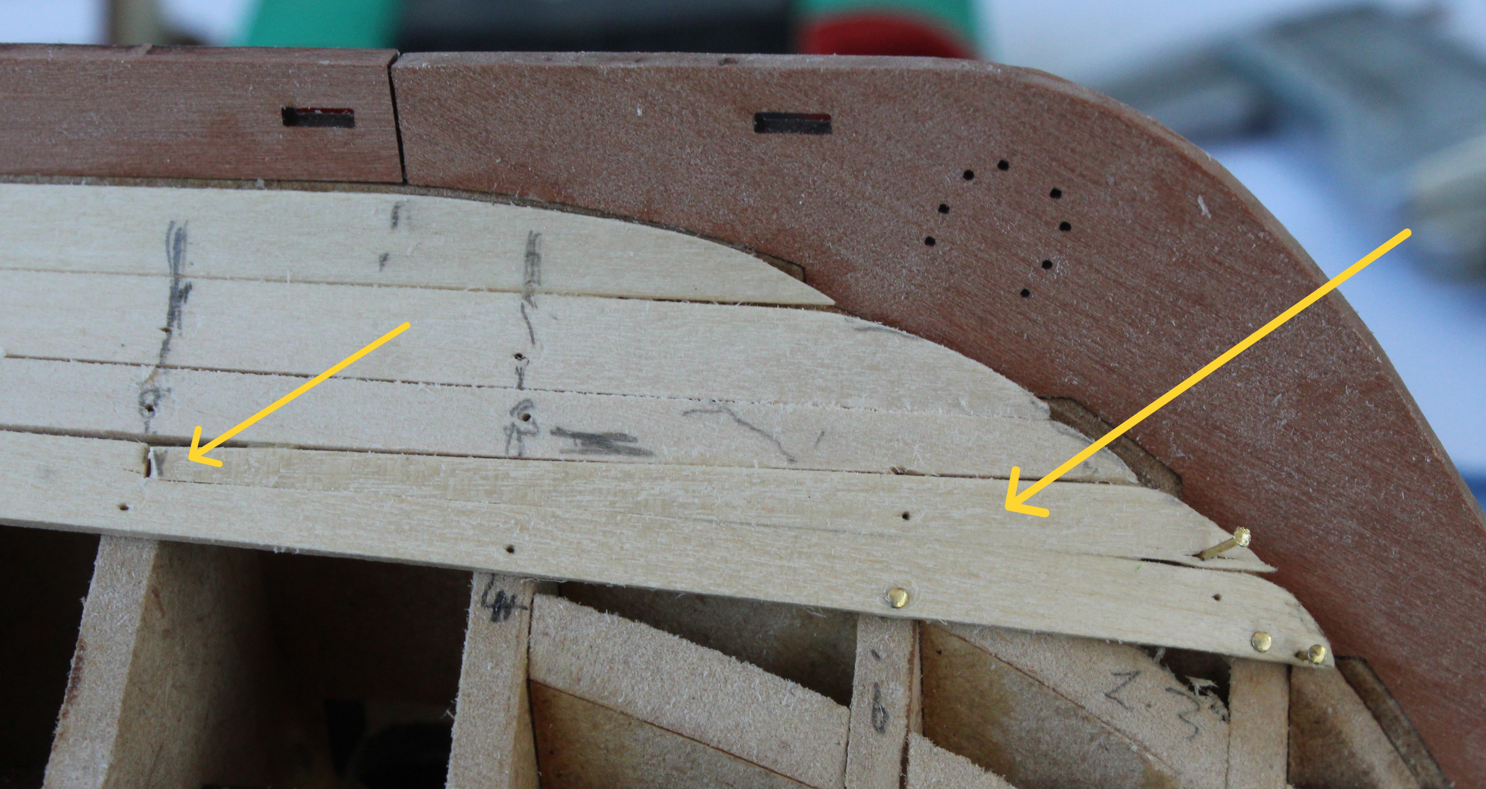
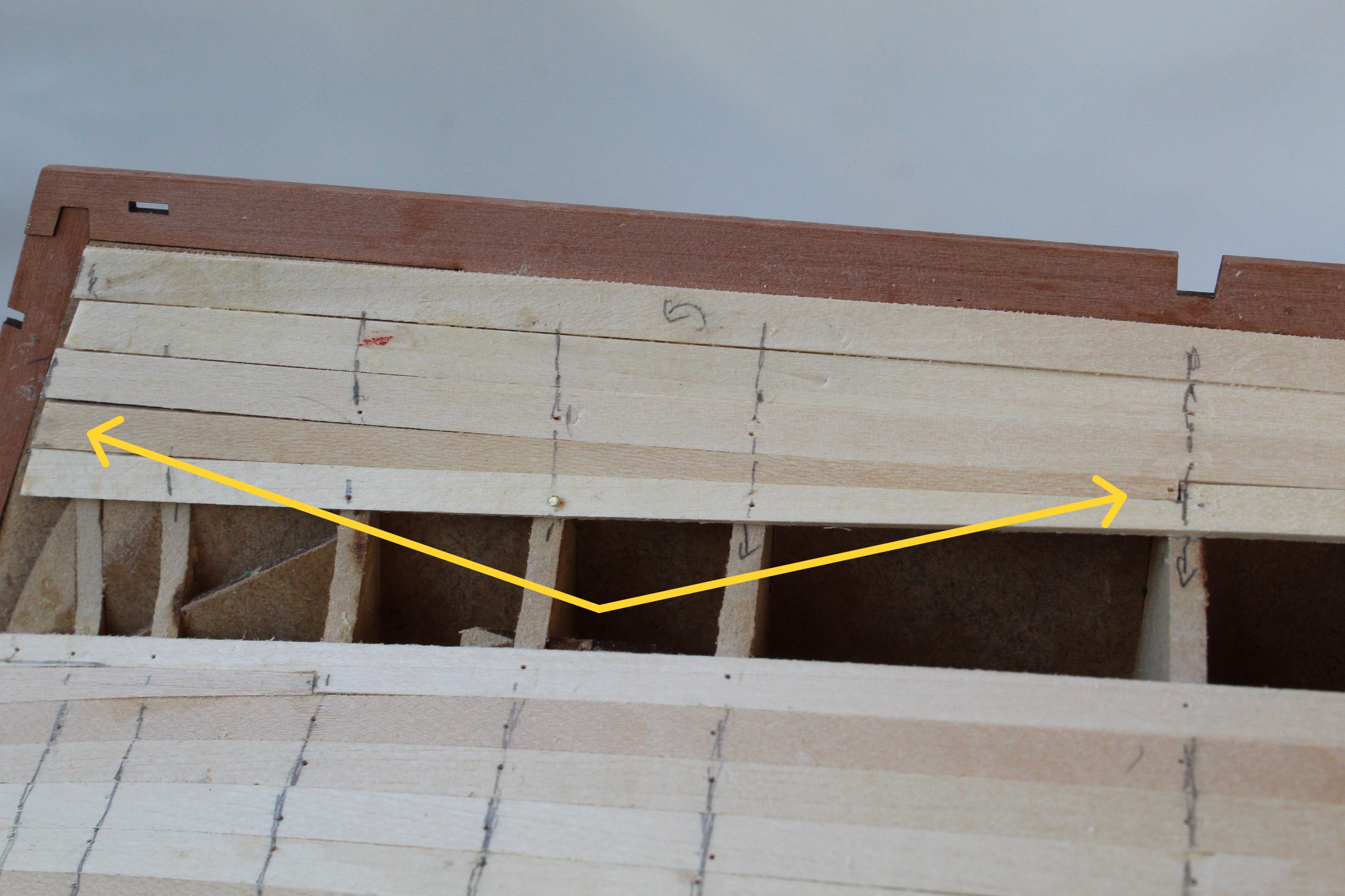
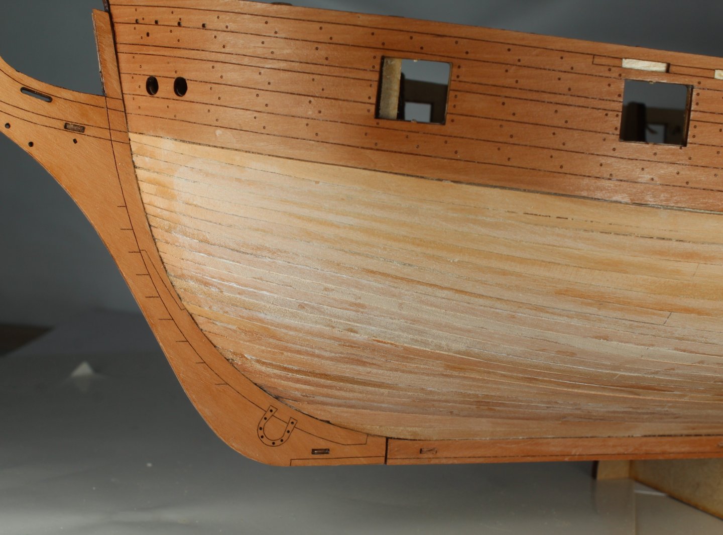
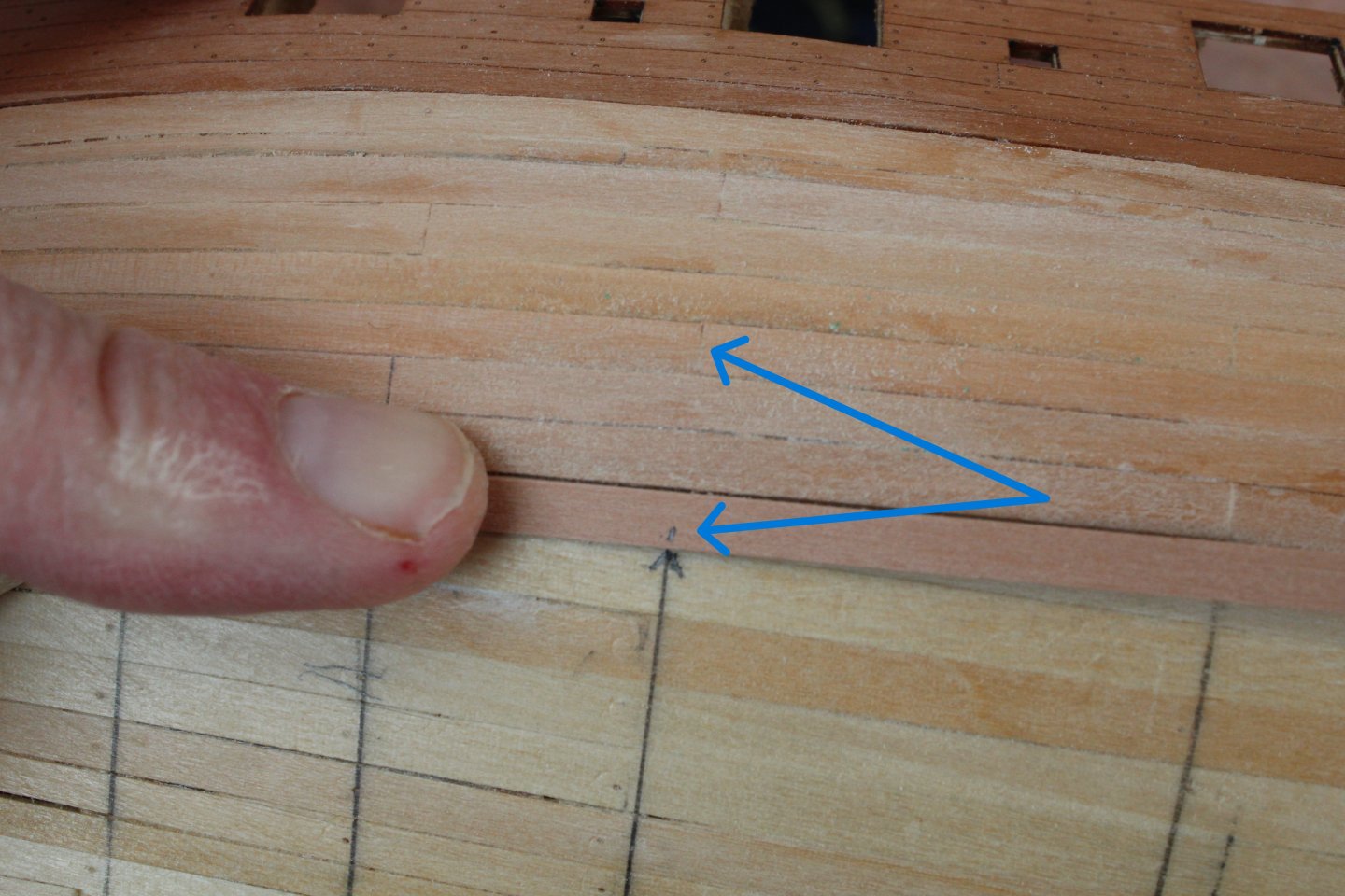
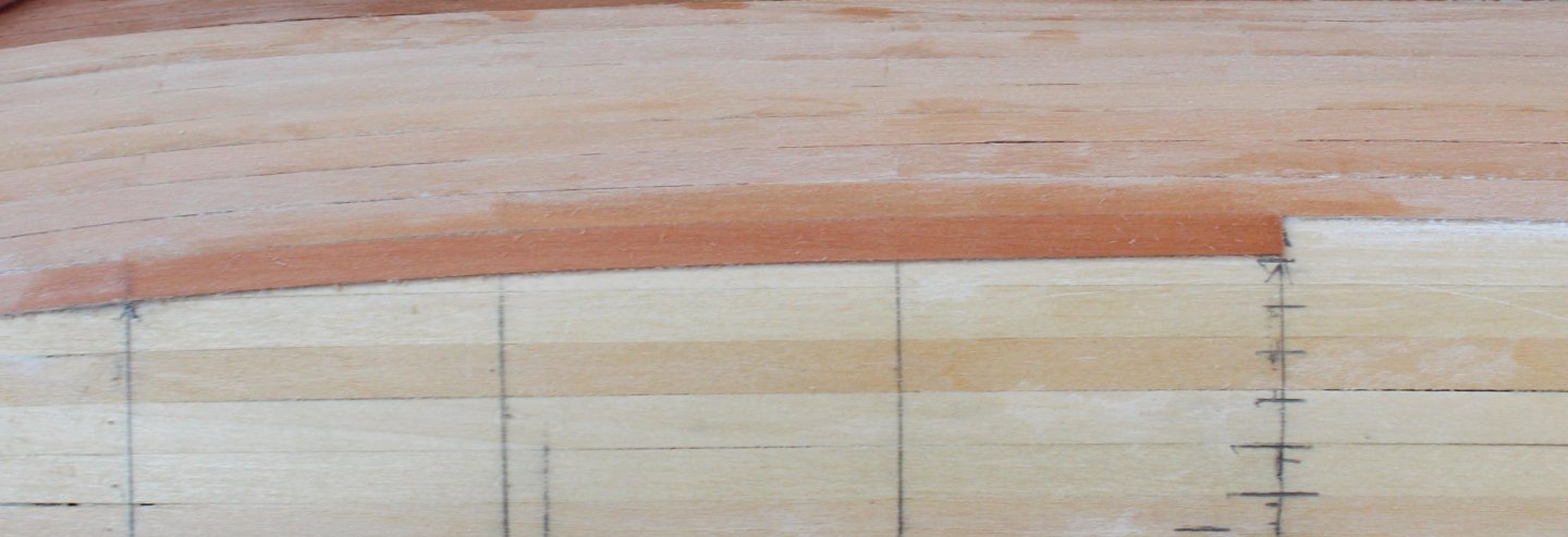
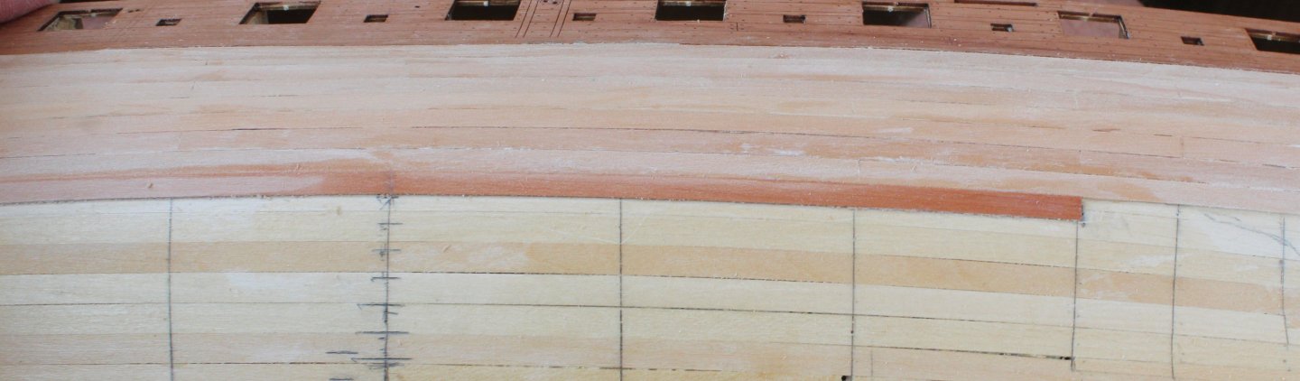
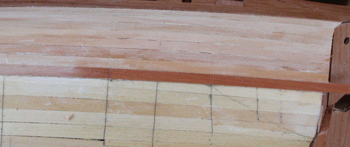
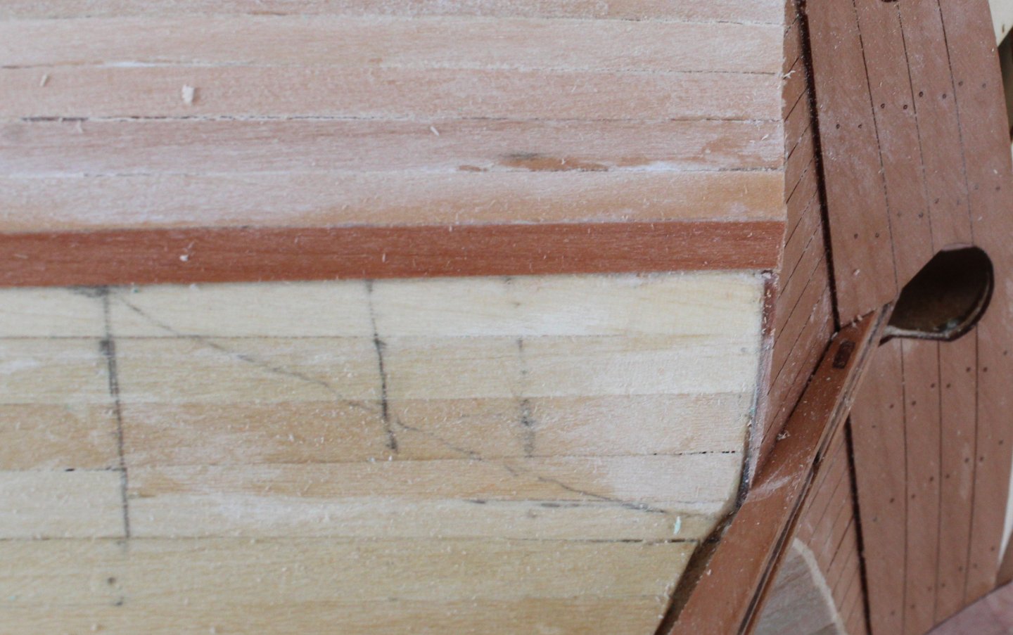
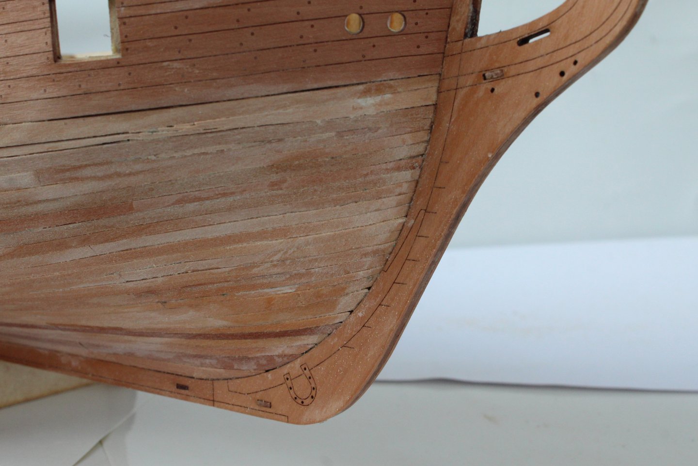
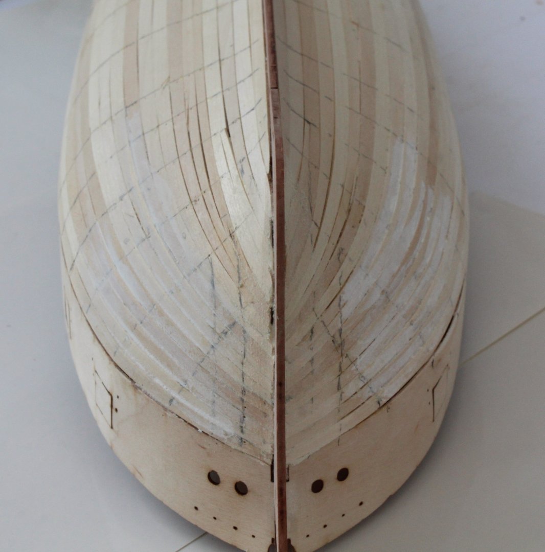
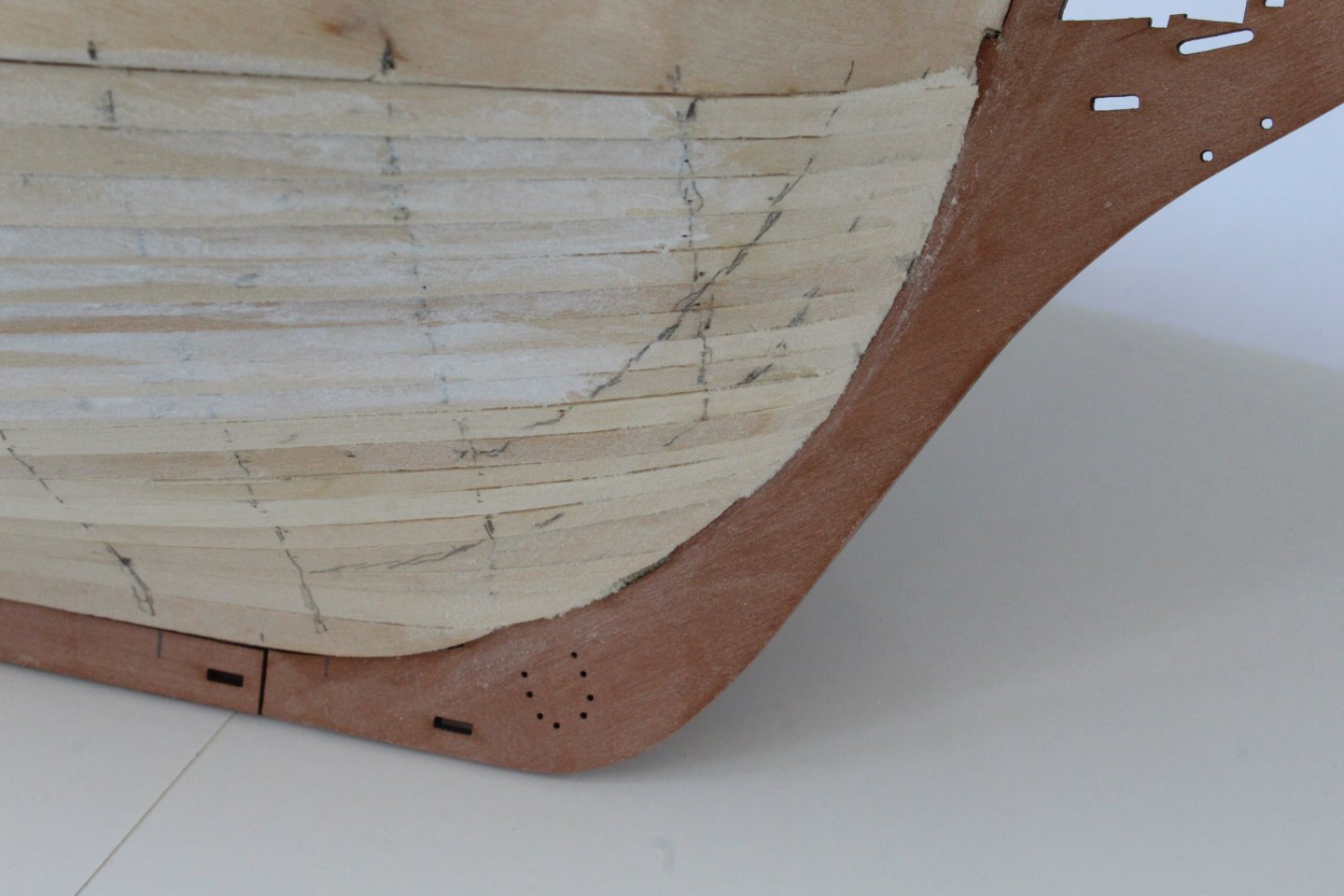
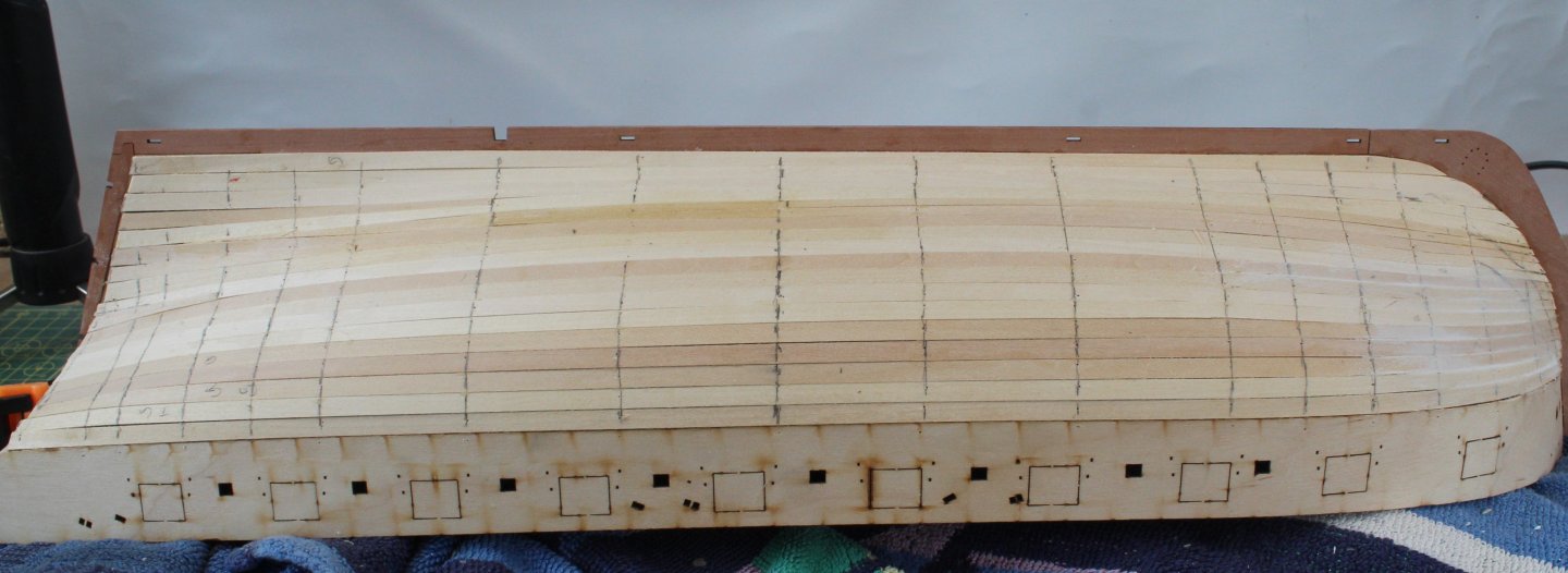
Work is progressing slow and steady on adding the second planking. I have now completed the planking on the right-hand side down to where the water line terminates at bow and stern. I have also added the garboard along the keel, comprising 2 x 4mm planks. I have continued to use shorter plank lengths (max approx 140mm). In the photo below the red arrows shows the position of the different plank joints, noting the pattern does repeat with every third strake. When fitting a plank I do mark the position of the next plank, as indicated by the blue arrow. The bow planking is looking reasonably Ok at the moment. I am colour matching the planks as I go along. The lateral bend is really helping and there is no real evidence of clinkering which is a first for me. In the photo below the CA glue stain will be hidden by the wale, when fitted. The blue arrow indicates where the plank width is tapered to 3mm and will taper to 2mm at the stem post. The final two photos shows the stern area. Once the plank ends have been sanded flush with the stern counter I am planning to add a square tuck finish. There is still a few days work left to complete the right-hand side before moving on repeat for the left-hand side.


- 241 replies
-
- 13
-
-
- Vanguarrd Models
- Harpy
- (and 1 more)
-
Many thanks Mark, much appreciated.
-
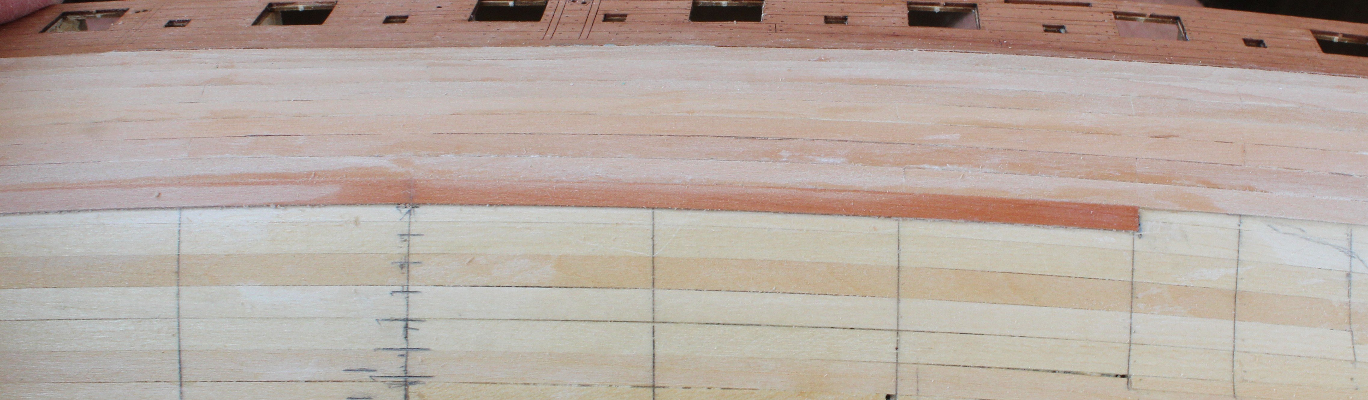
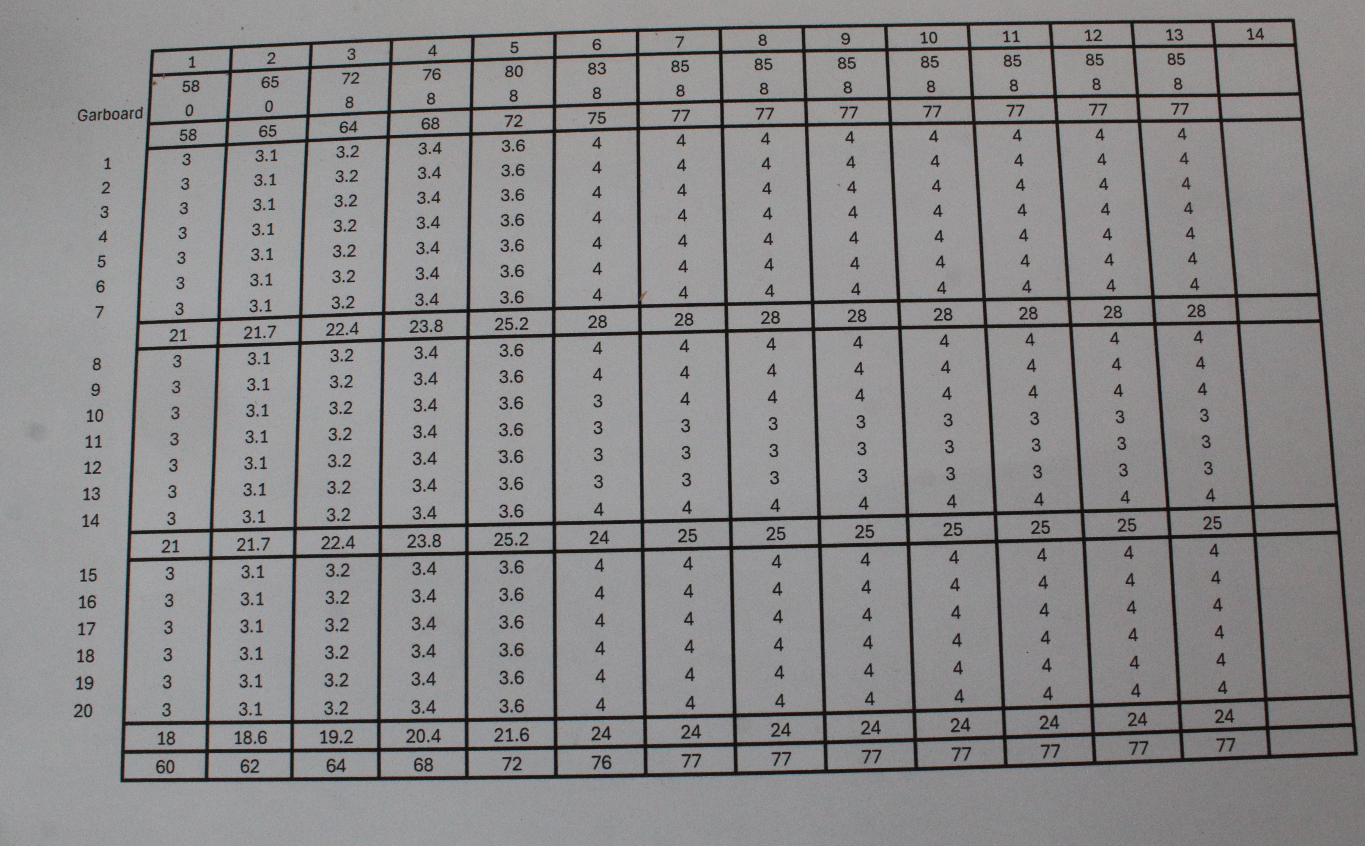
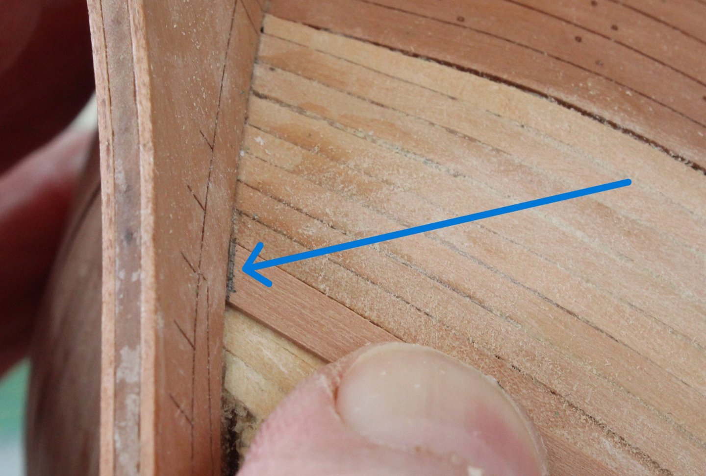
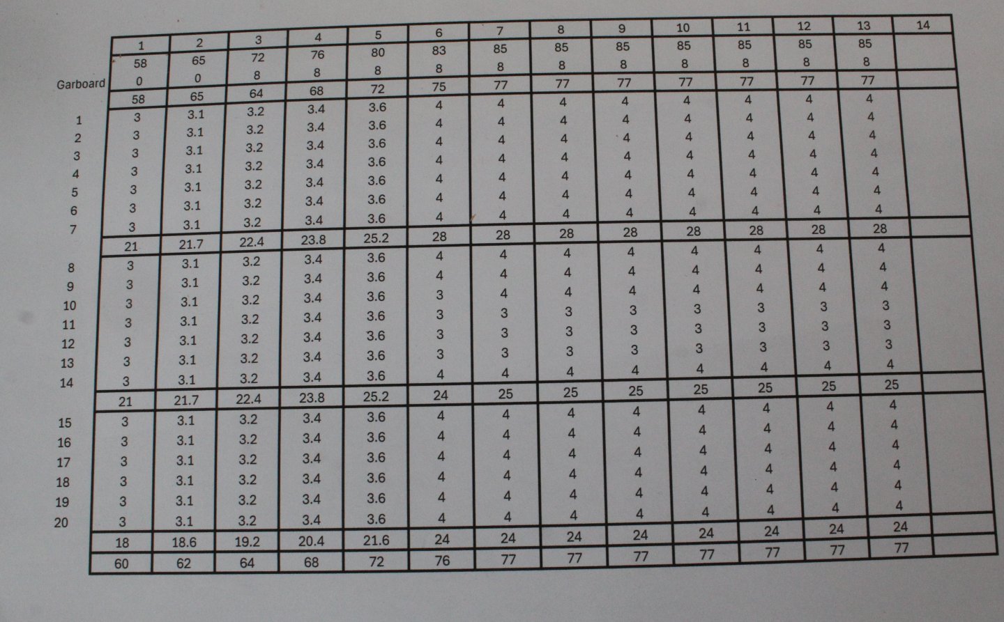
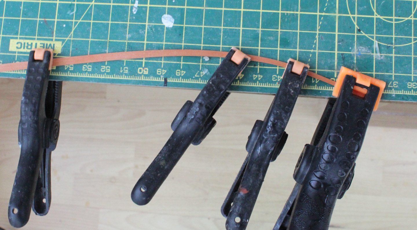
There is quite a lot colour variation with the kit supplied second planking material. Also there are a few planks that have manufacturing defects, such as ripped edges and tapering. I have sorted through and will use the best planks for the area beneath the wales and above the water line. The quality and colour variation of the kit supplied second planking material is not a issue when the hull is either painted or coppered. The Harpy will be coppered below the water line. If going for a natural wood, varnished finish to show of the planking then it is probably better to replace the second planking material with high quality milled timber from a supplier such as Hobbymill EU. My planking is not up to that standard as yet. I ended up following the same method as @Blue Ensign with regards adding the two strakes that sit beneath the wales and then trimming the excess material so the next strake will follow the same line as the bottom edge of the wale. Once that was done I took some measurements and created a schedule for the planking between the bottom edge of the wale and the garboard. I am not going to taper the stern planks and will simply add stealers as and when necessary. In the next photo I have added the first four strakes that sit beneath the wale. The blue arrow indicates where the strakes added that sit beneath the wale. I have use the planks that were the worst with regards to colour matching for this area. When adding the second planking I am fitting planks of approx 140mmL and making joints on the bulkhead lines. In the next photo you will see where the various joints have been made. The next photo shows how the stern looks, noting the blue arrow shows the planks that will be hidden by the wale. The following set of photos shows the process I am using to add planks in a bit more detail. Once the plank has been tapered as per my planking schedule it is wetted and then clamped to my workbench so a lateral bend can be applied. I use a hairdryer to apply heat to the dampened plank for approx. 1 minute. The laterally bent plank is then test fitted. The plank looks a good fit in the photo below. The plank is then cut to length, using a guillotine. In the next photo the second plank has been added. I slightly dampen the plank before gluing as the adhesion with the CA is much quicker. When adding the stern plank I like to add a slight twist to get a good fit. In the final photo of this photo the stern plank has been fitted. The blue arrow shows the approximate position of the water line.


- 241 replies
-
- 9
-
-
- Vanguarrd Models
- Harpy
- (and 1 more)
-
I use Guild Materials Sanding Sealer, GLDCEX1100125
-
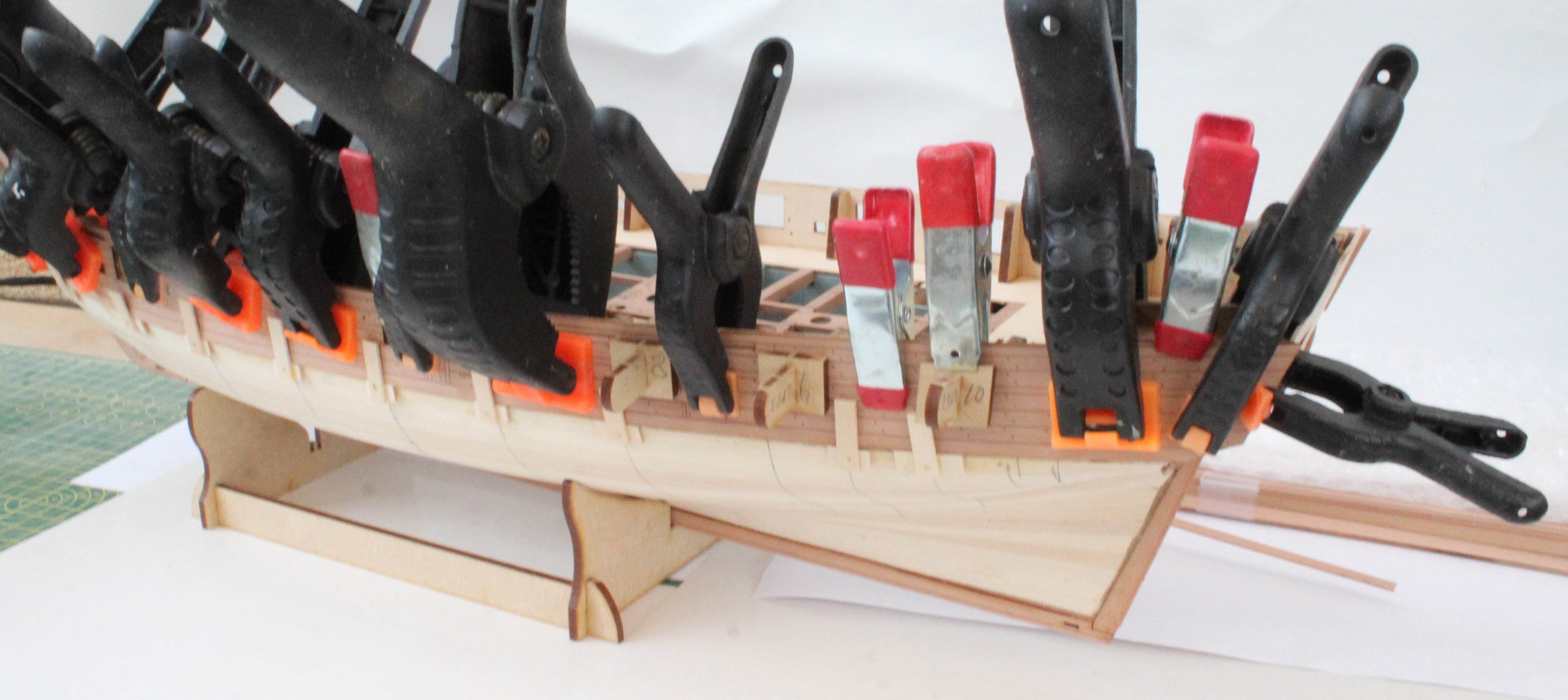
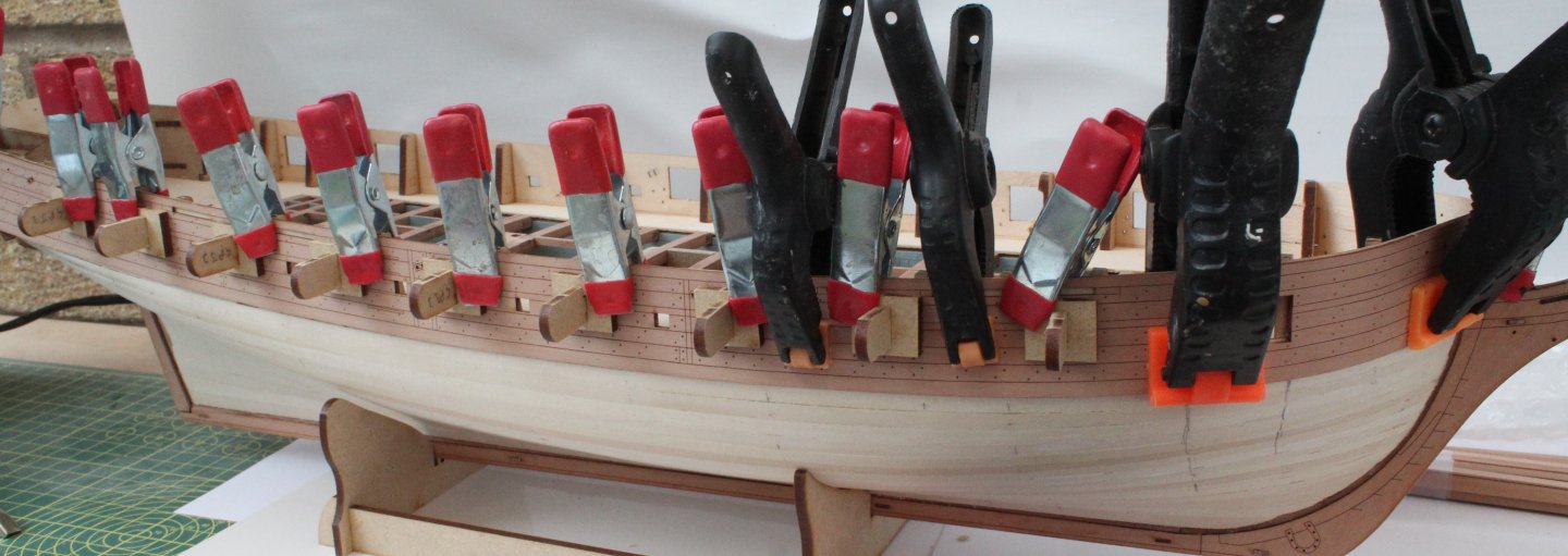
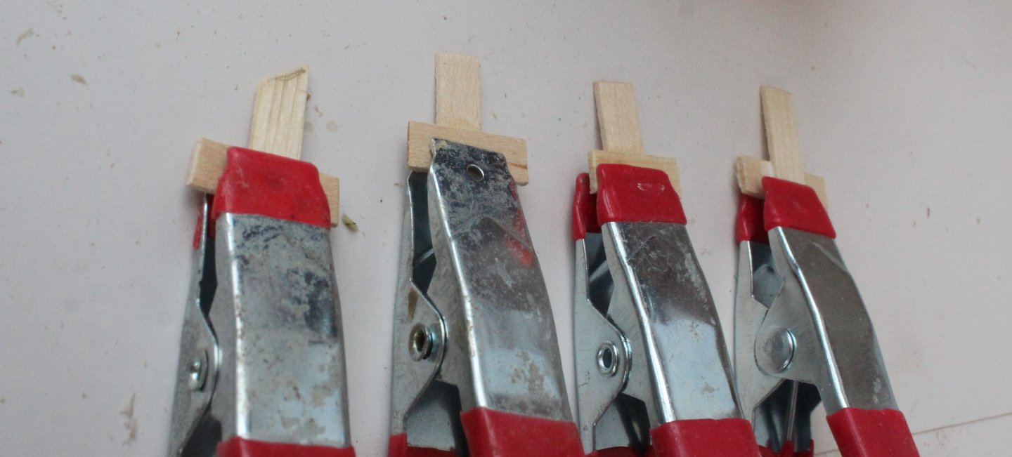
The outer bulwark patterns have now been added to the hull. I used a variety of clamps to hold the patterns in place as the glue was curing. I did find it necessary to use my hand made clamps to ensure the bottom edge of the patterns were in contact with the hull. Once the patterns had been clamped in place all the gun port jigs were removed to ensure they were not accidently glued in place. When the clamps were removed I was reasonably happy with how they looked. When reading some of the other build logs there were some different approaches made to the second planking with regards to how the planks will align with the wale patterns. I have marked the line where lower edge of the wale will sit of the hull as shown in the photo below. My plan is to add a plank aligned with the marked bottom edge line and then to infill the area between that plank and the bulwarks. Before starting the second planking I applied a coat of sanding sealer to the hull. The position of the bullheads are marked in case I decide to use them should I wish to add some pins when planking below the water line. I will add a line for the waterline before I start to add the second planking. I plan to follow @Blue Ensign lead and use individual plank lengths of approx 140mm, with a minimum length of 60mm for the planking between the wale and waterline.


- 241 replies
-
- 9
-
-
- Vanguarrd Models
- Harpy
- (and 1 more)
-
Hello Maurice You hard work and attention to detail is paying off as the coppering looks great. Thanks for a very informative post (once again). Glenn (UK)
- 332 replies
-
- 2
-
-
-
- Harpy
- Vanguard Models
- (and 1 more)
-
The paint job looks great
-
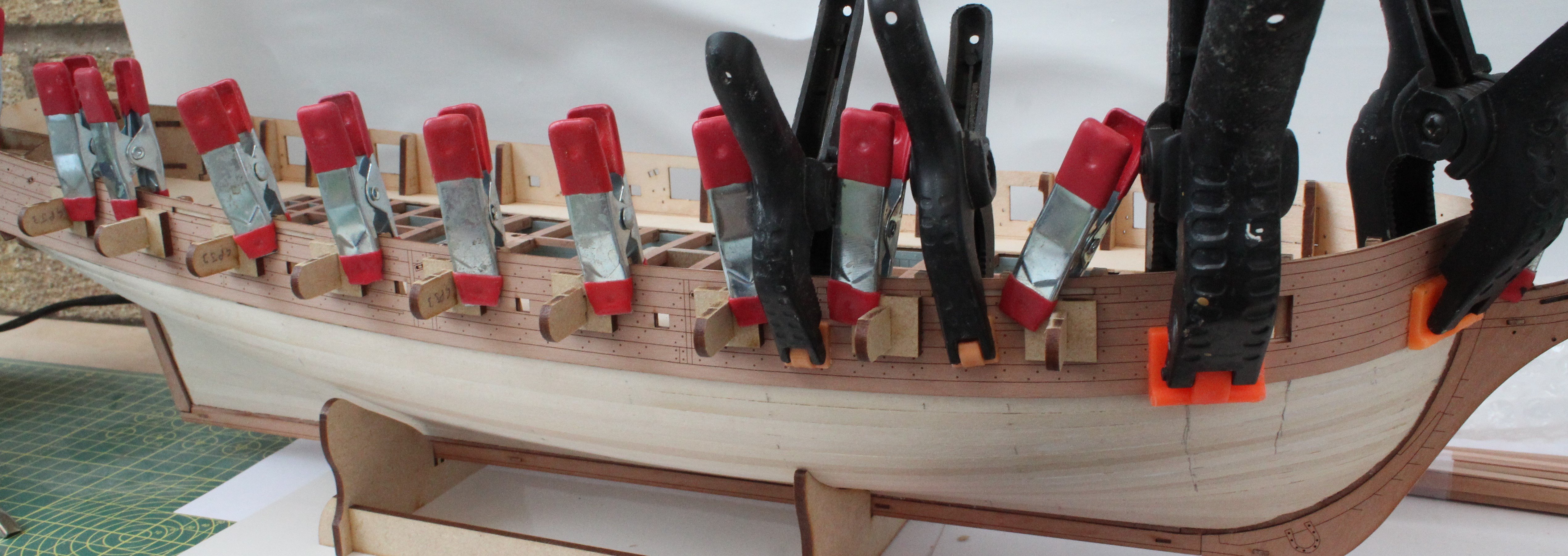
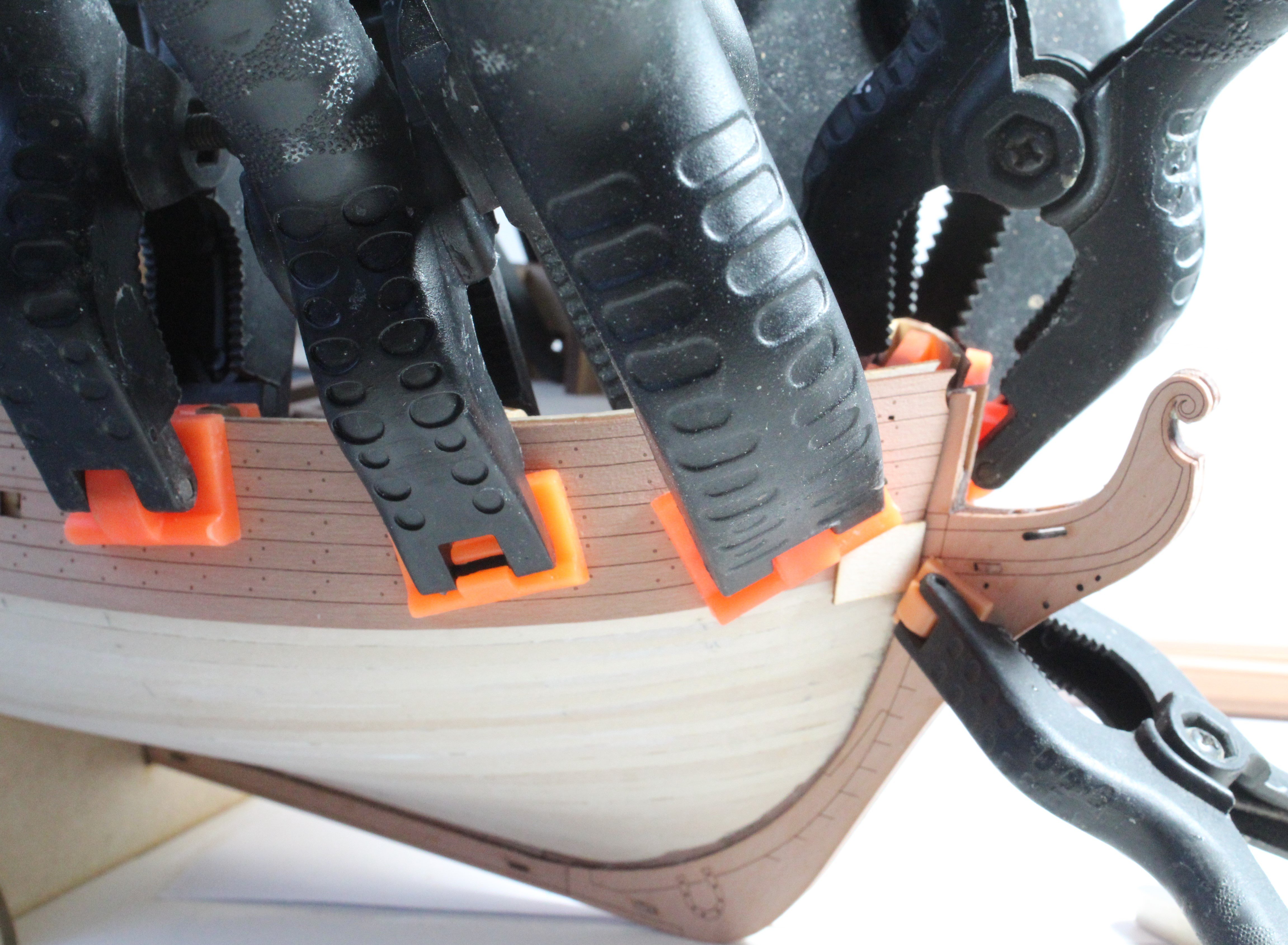
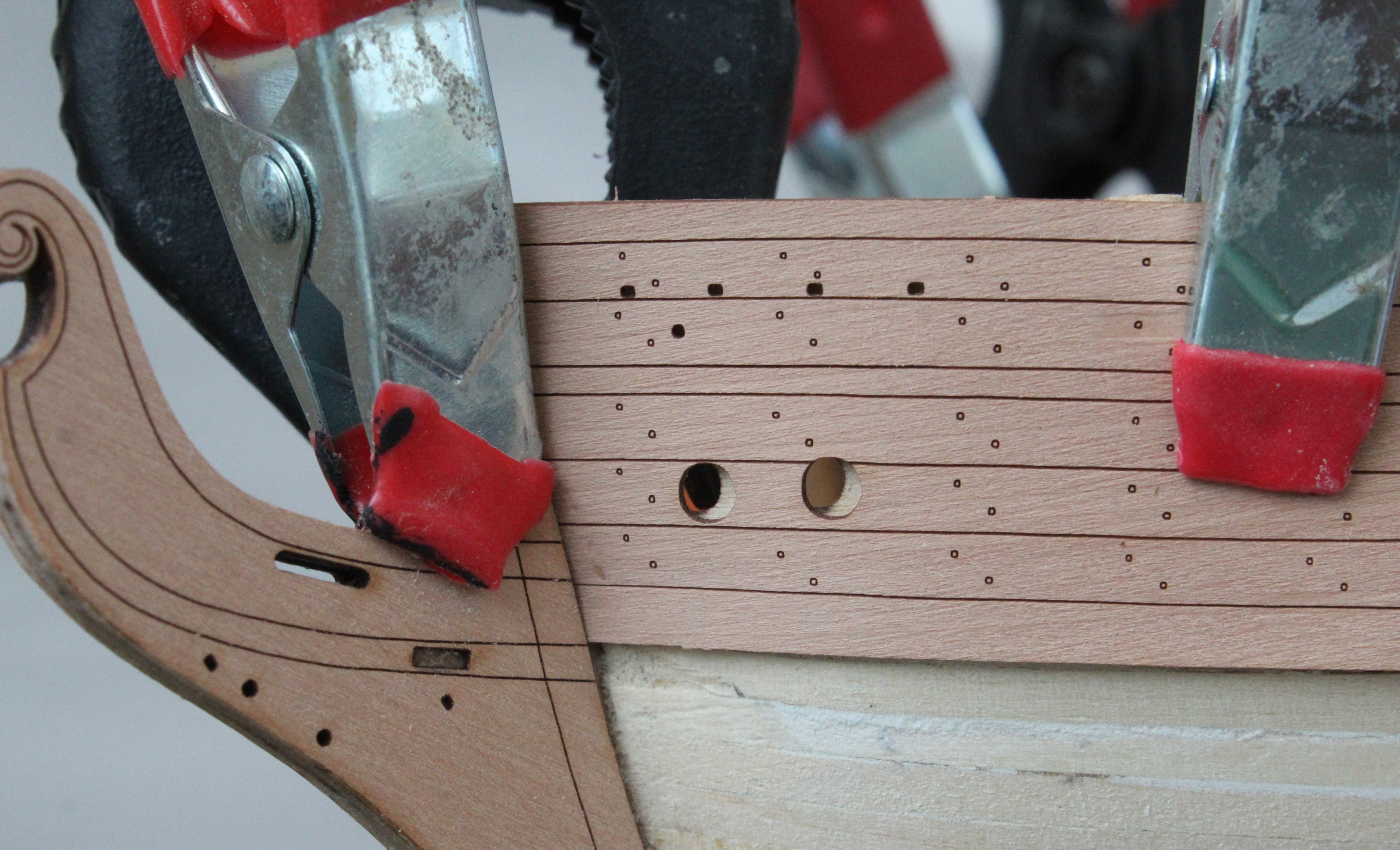
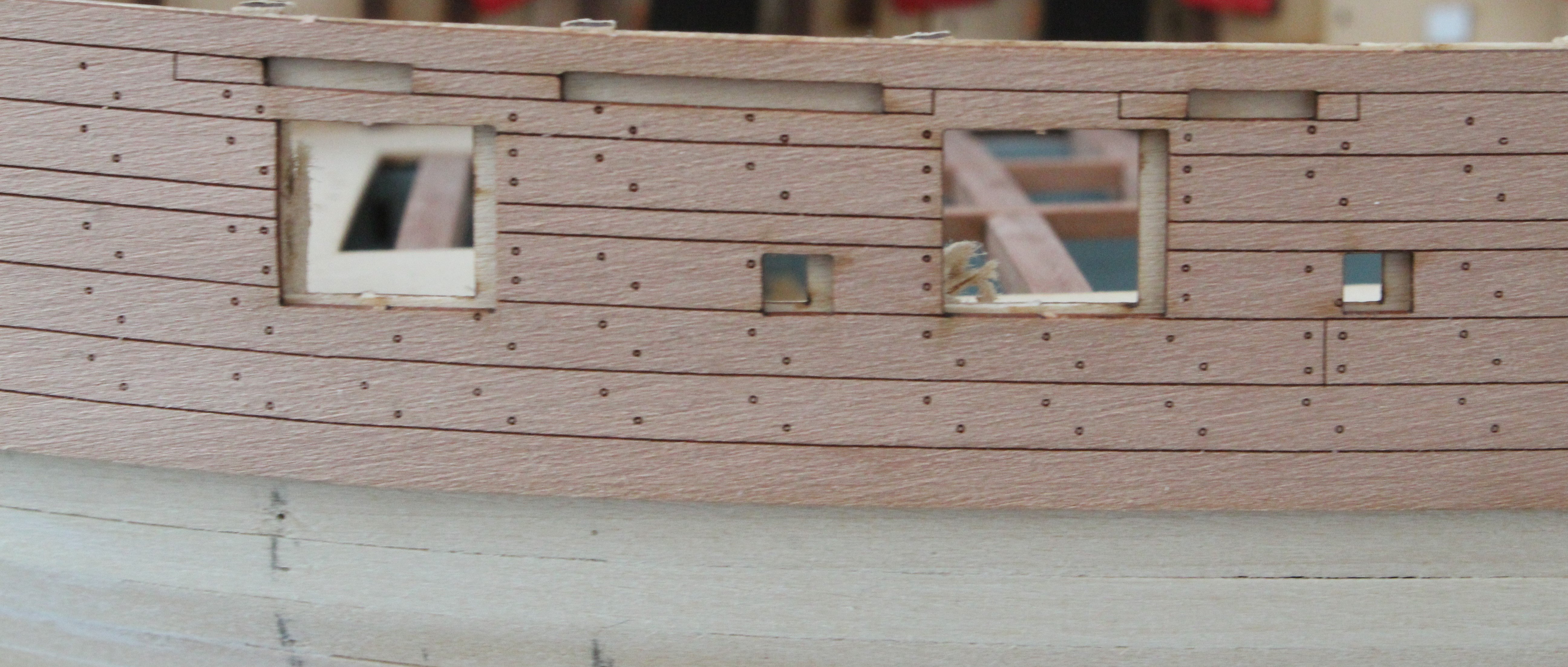
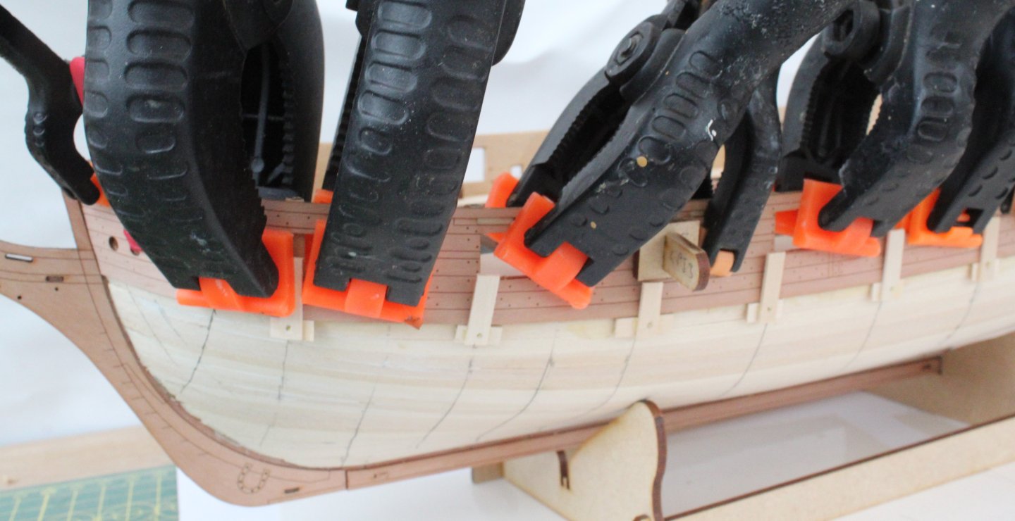
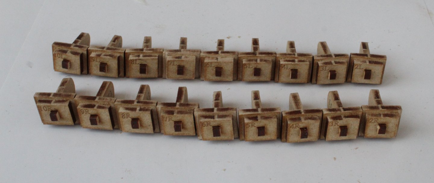
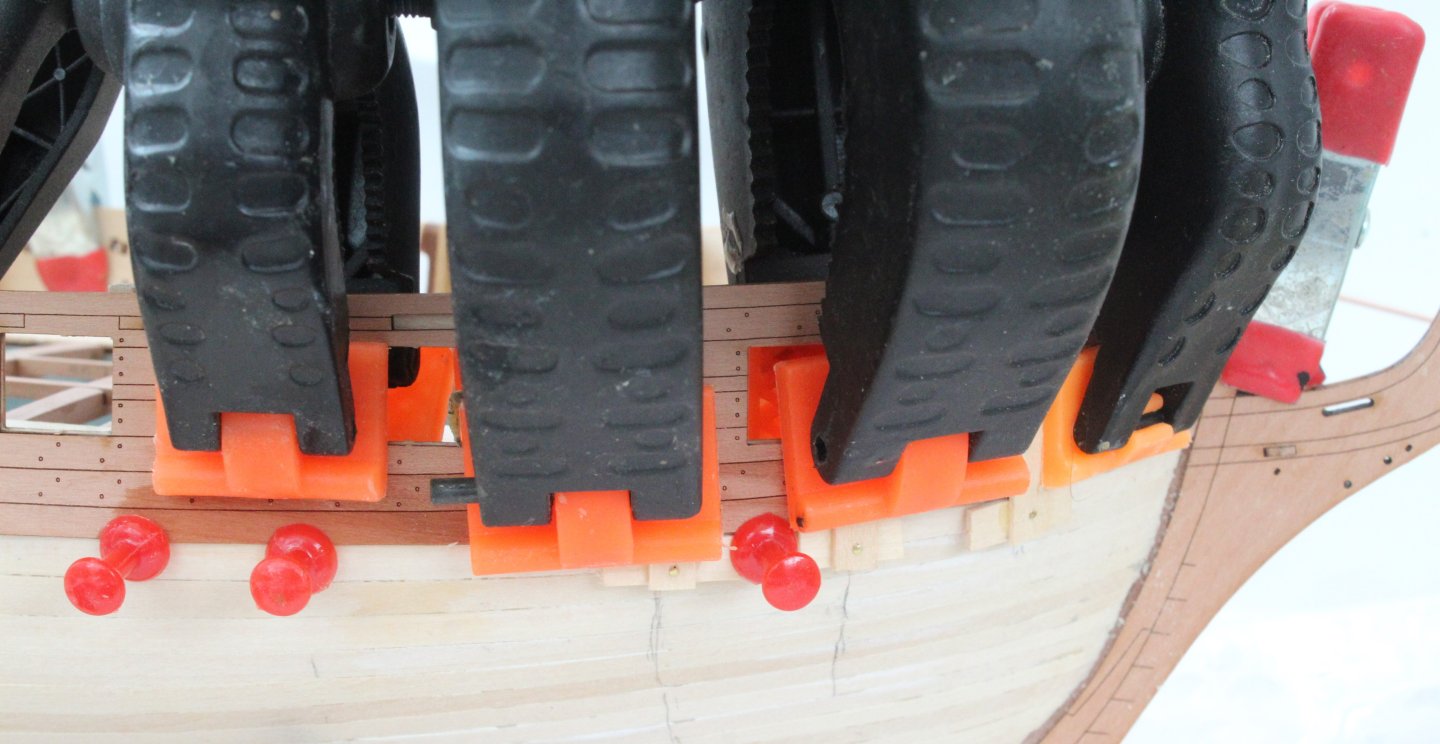
The next task in the build process is to add the outer bulwark decorative patterns. To assist with the aligning of these patterns the kit is provided with a set of gun port jigs. Each gun port jig has a laser engraved position identifier. When test fitting these jigs I did notice the ones marked as 2L through to 10L are shaped for the right hand gun port openings side and the ones marked as 2R through to 10R are required for the left hand side gun port openings. The outer patterns, after being soaked in warm water, were clamped to the hull and left to dry out overnight. I used plenty of clamps for the bow area. Once the patterns had fully dried out the the right-hand pattern was carefully aligned. I did shave approx. 0.5mm from the bow end of the pattern before I was happy with how the pattern lined up, with the hawse holes and with all the gun port jigs fitted. It was necessary to trim some of the bulkhead ears to allow the gun port jigs to be full inserted. With previous builds I would have been happy to proceed to gluing this pattern in place. However as I noted that the bottom edge of this pattern was not sitting flush with the hull I felt I should try to address this issue. Please see the next photo where shows the problem. The uses of clamps did not solve the problem therefore I decided to resoak the planks in the problem area and to then add some additional clamps and pins positioned below the pattern to try to close the gap. I fashioned some suitable clamps using some spare planking material. As can be seen in the next photo the pattern has been wetted and a combination of clamps & pins have been used. Hopefully, once the pattern has dried out, the pattern will be a better fit along the bottom edge of the hull. When checking the position of the left hand pattern I noted that I will need to trim approx. 2mm from the bow end to ensure the pattern aligns with the hawse holes and gun port openings. This can be seen with the final two photos of this post.


- 241 replies
-
- 7
-
-
- Vanguarrd Models
- Harpy
- (and 1 more)
-
Hello Maurice Great work on the coppering and choice of CA. I have one question which is "What burnishing stick are you using?" I have followed you lead with regards to the square tuck which looks great on your model. Cheers Glenn (UK)
- 332 replies
-
- 1
-
-
- Harpy
- Vanguard Models
- (and 1 more)
-
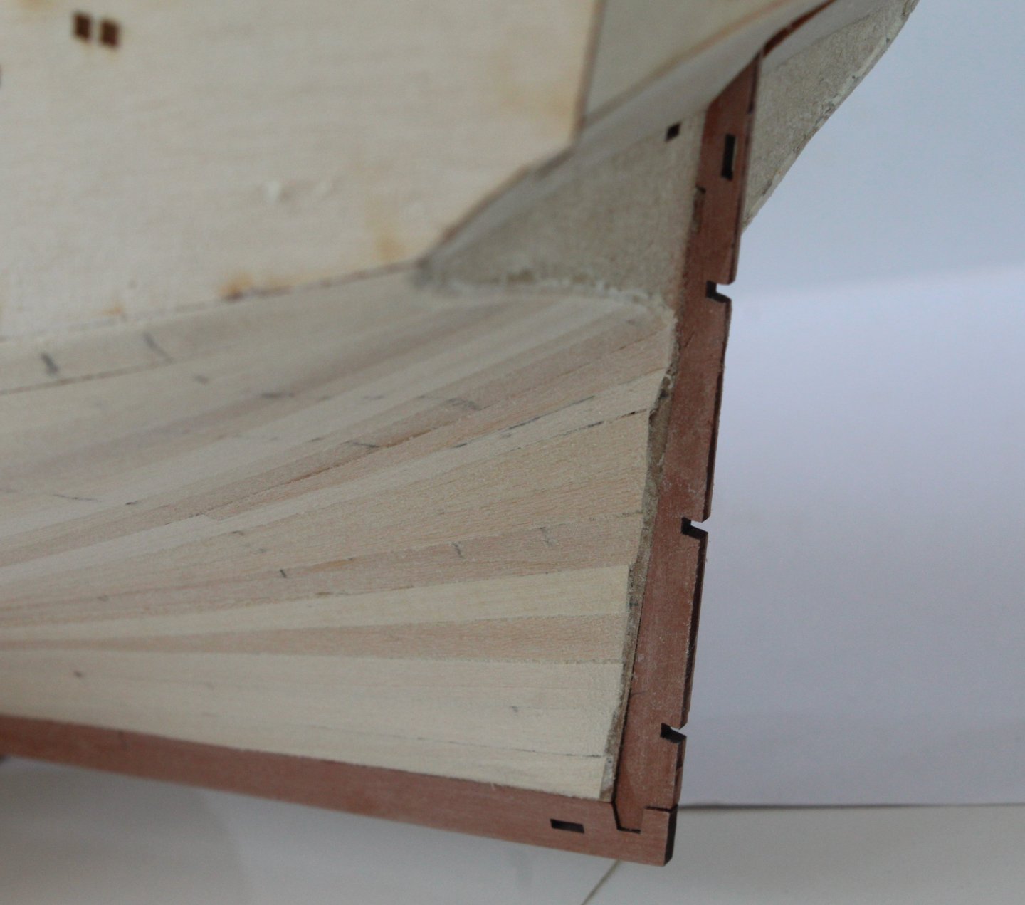
The Square Tuck When looking at @Blue Ensign excellent and very information build log for the Harpy I really liked his square tuck enhancement. I decided it was worth investigating weather I could follow his lead in this respect. Using the two stern counter patterns as a template I draw the required shape on some excess pear wood. I did made the lower square cut patterns using some 1 mm pear wood scraps but as the infill would be 0.8mm thick planking material I made another pair from 0,8mm pear wood scraps. I did not have the luxury of a jigsaw to cut these parts but I was able to cut the parts out using a sharp bladed craft knife. In the next photo you can see I am checking the contour of the pattern matches the stern counter pattern. With the two stern counter patterns glued in place the lower square cut patterns are checked and look OK. A little bit more work may be required once the second planking has been completed. I forgot about the stern post outer patterns, so the square tuck patterns were checked again after the outer patterns were test fitted. Once that was done I made the two top sections required for the square cut. I think they pass the initial inspection so I will put these parts to one side for the time being and proceed on with the build, I will add a planked infill, as per @Blue Ensign build method. It has been an interesting little side project and one I am pleased to have tried.


- 241 replies
-
- 11
-
-
- Vanguarrd Models
- Harpy
- (and 1 more)
-
Thanks Mark
-
Thanks Bob
-
The first planking task is now complete. For the most part I am really pleased with how the hull looks. There are a few strakes I could have done better but overall my planking is improving with each build. Using a mixture of my mouse sander, sanding sticks and sand paper the hull has now been sanded smooth. I have used both the sight and feel test and all looks good and feels smooth. I will still need to do some more checks with regard to how the second planking will look after the outer patterns have been test fitted to the stem post, keel and stem post as the second planking is to sit flush with the outer edges of the keel and stern post patterns. I also need to check the second planks will fit in the rabbet that is created when these outer patterns have been added. Once I am happy with everything I will apply a coating of sanding sealer to the hull.


- 241 replies
-
- 15
-
-
- Vanguarrd Models
- Harpy
- (and 1 more)
-
I shall be interested to see what you do with fitting the wales as I am currently a few days behind you with my Harpy build.
-
Thanks Mark
-
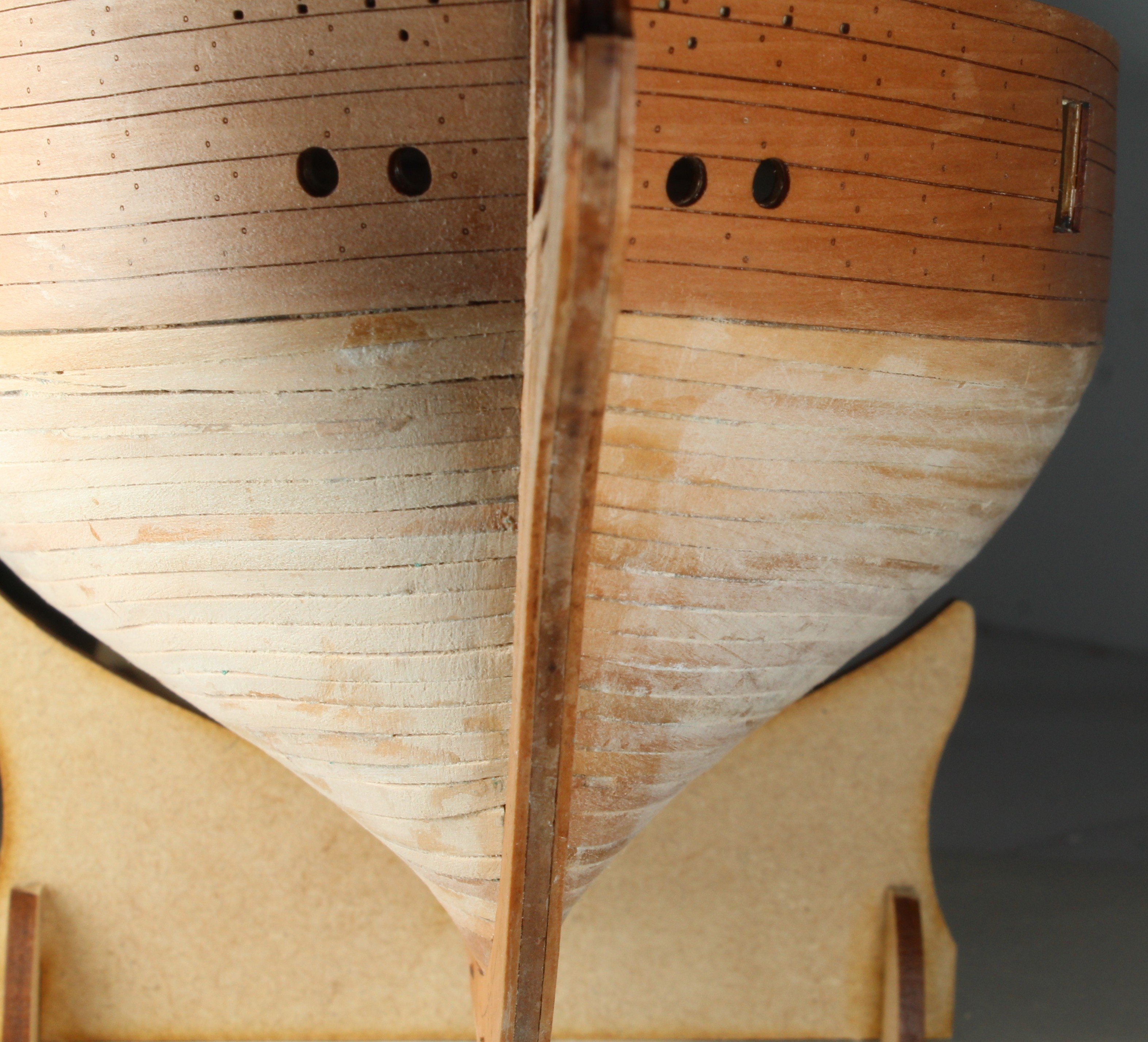
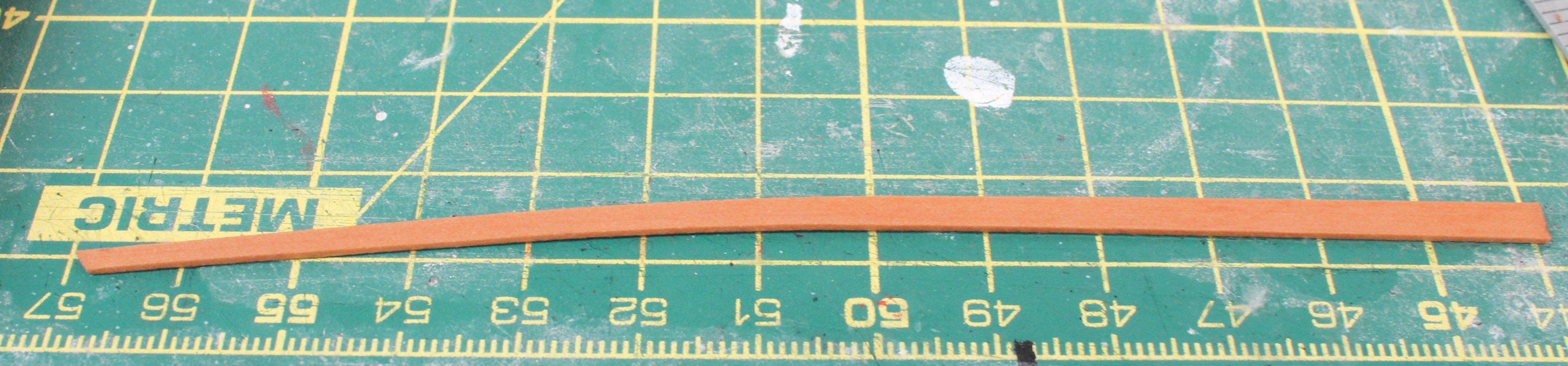
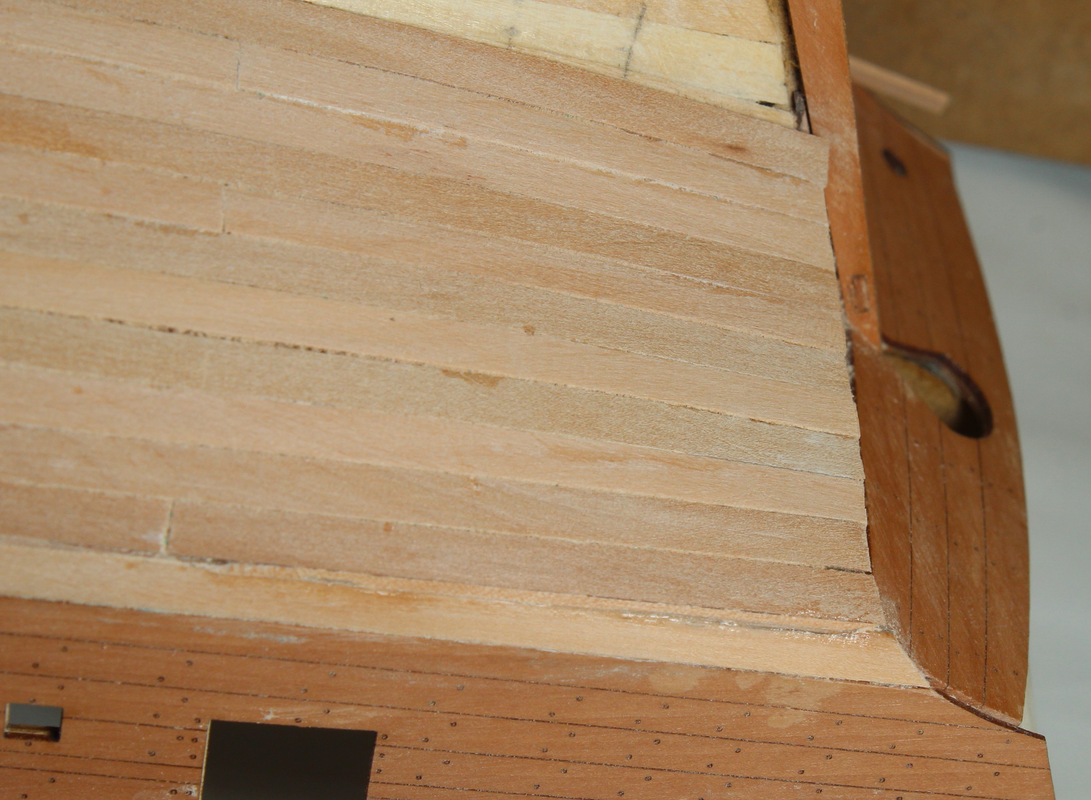
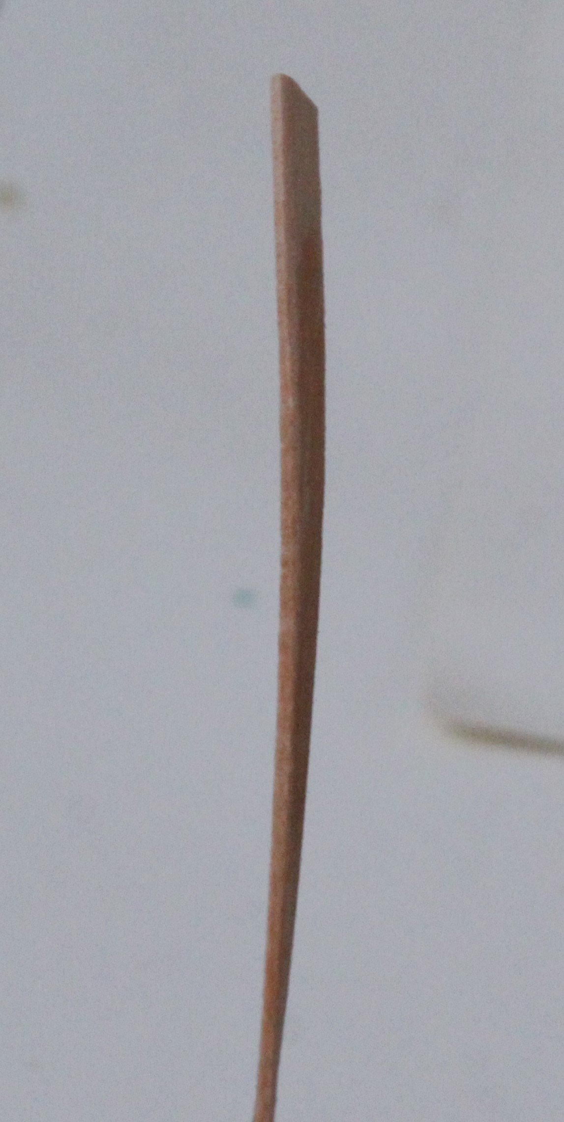
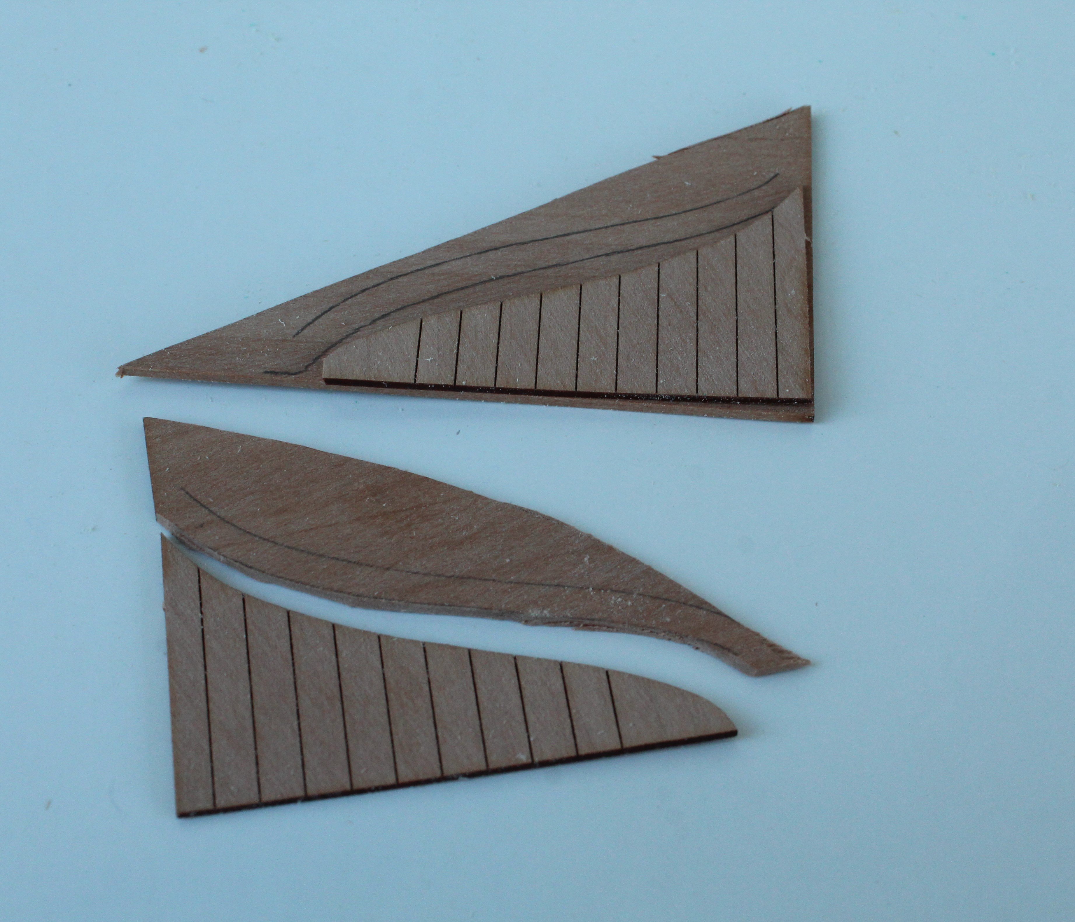
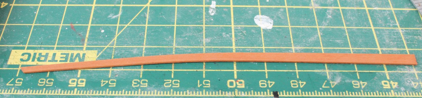
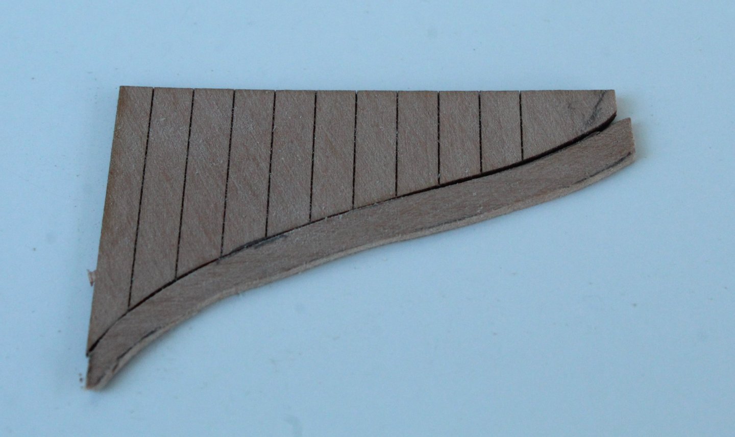
The first planking of the Harpy continues but the end is near. I hope to have to completed later in the week, all being well. After adding the first 8 strakes to both sides I turned my attention to adding the garboard planks (to both sides). In the two photos below you will note that I have cut the stern end of these strakes a tad short of the stern post which is intentional as this will aid the sanding process to ensure the second planking (when added) sits flush with the stern post. I have found it necessary to add one dropper strake (bow) and three stealers strakes (stern). I have attached a couple of photos of these strakes. Dropper Strake Stealer Strake I have completed the first planking on the left-hand side, as can be seen below I am very pleased with how the stern area is looking, and if you look closely the three stealers can be seen. The bow area looks Ok, you may notice in the following photo I have brushed in some diluted wood filler in the gaps. As I worked on the bow area I got a better understanding of the nature of the lateral bend and why it is necessary, I also (eventually) realised when adding the last few stakes that, in most cases I needed to add a bigger lateral bend to get a better neater fit. The starboard side first planking is almost complete and should be completed in the next couple of days.


- 241 replies
-
- 13
-
-
- Vanguarrd Models
- Harpy
- (and 1 more)