HOLIDAY DONATION DRIVE - SUPPORT MSW - DO YOUR PART TO KEEP THIS GREAT FORUM GOING! (83 donations so far out of 49,000 members - C'mon guys!)
×


Glenn-UK
-
Posts
3,162 -
Joined
-
Last visited
Content Type
Profiles
Forums
Gallery
Events
Everything posted by Glenn-UK
-
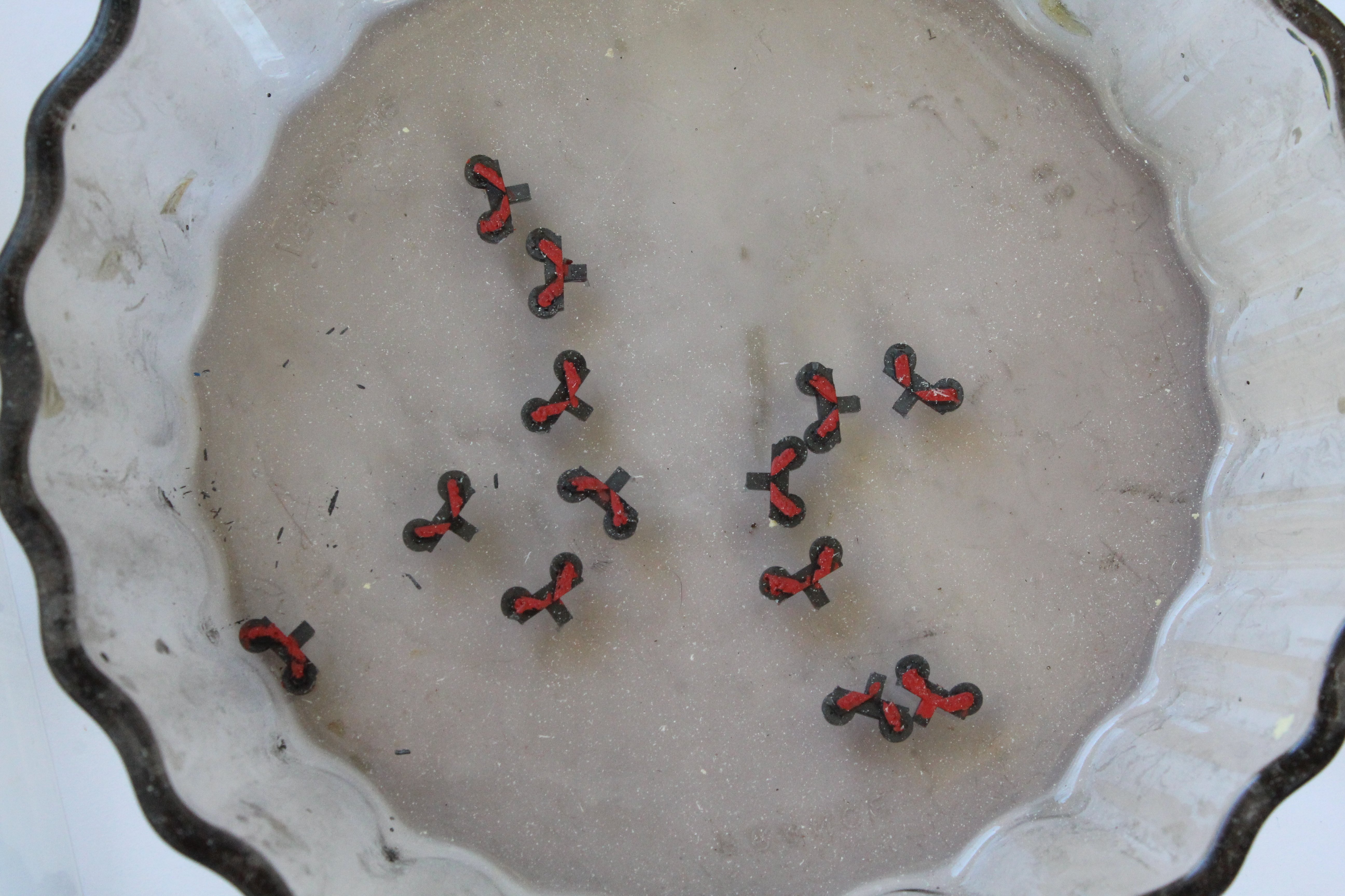
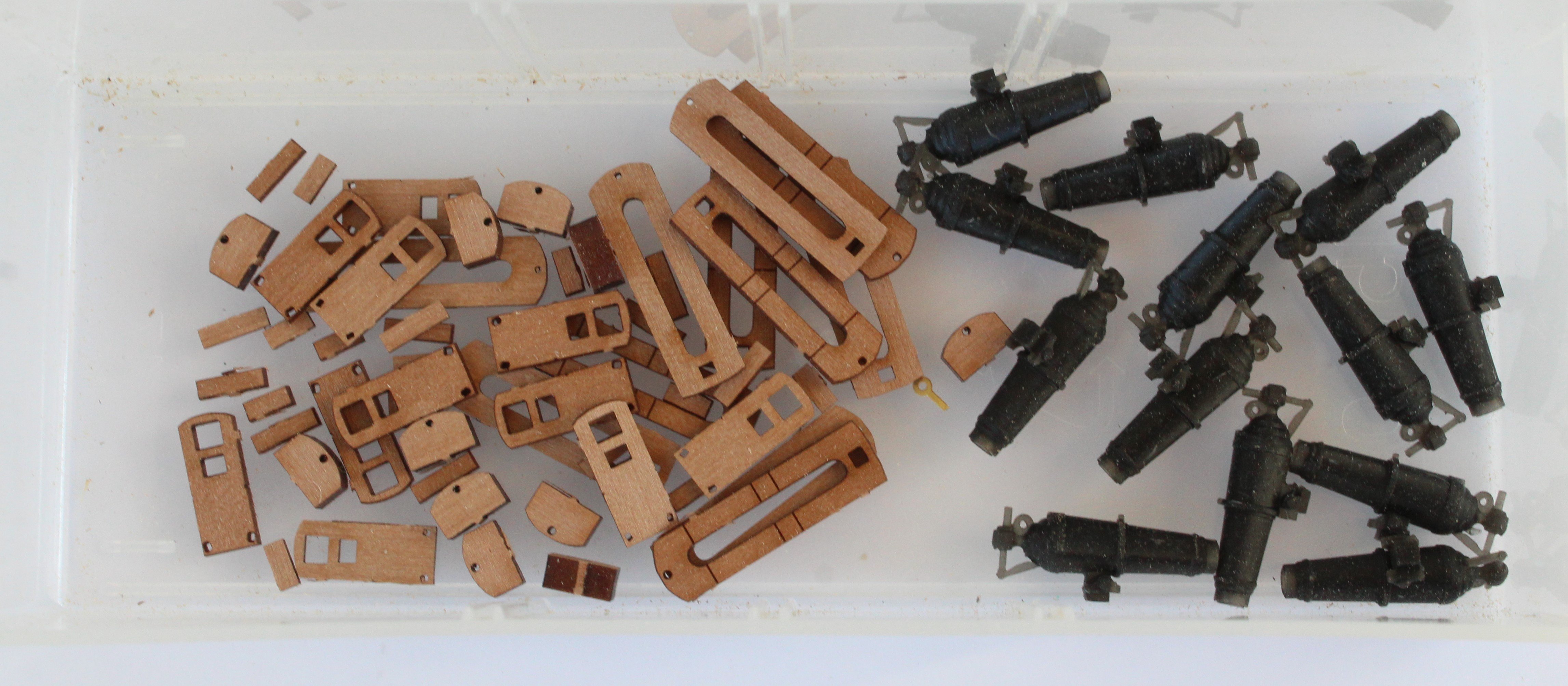
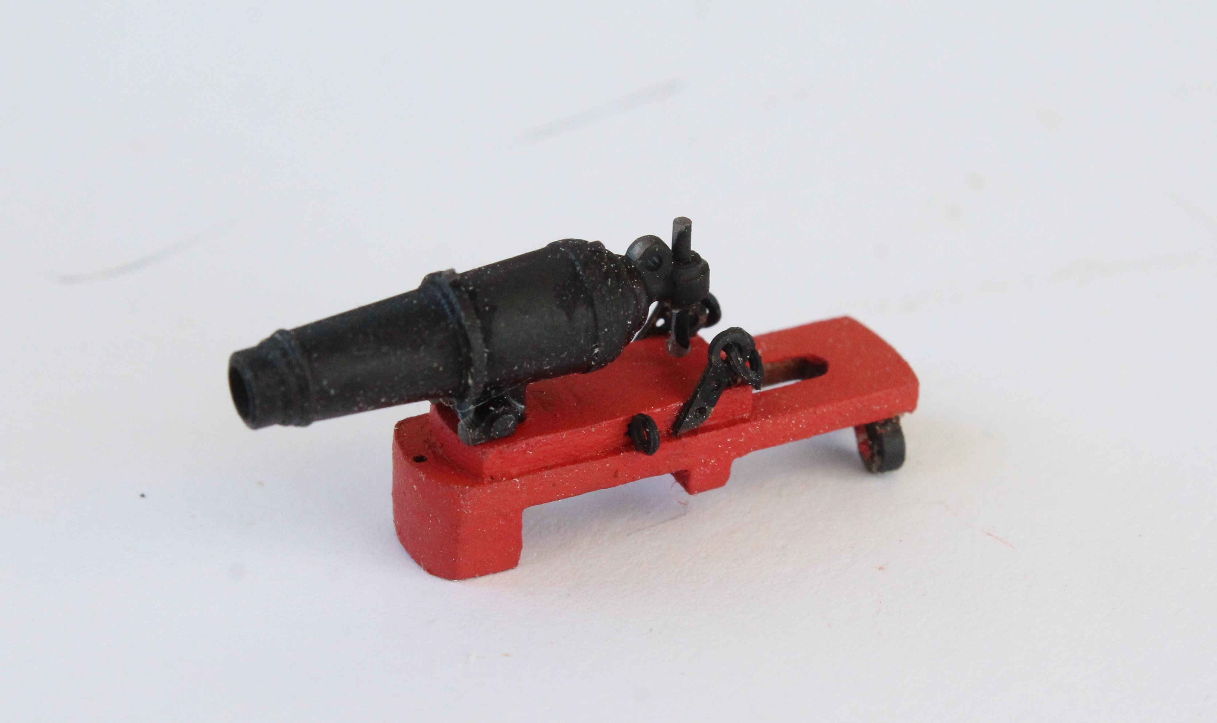
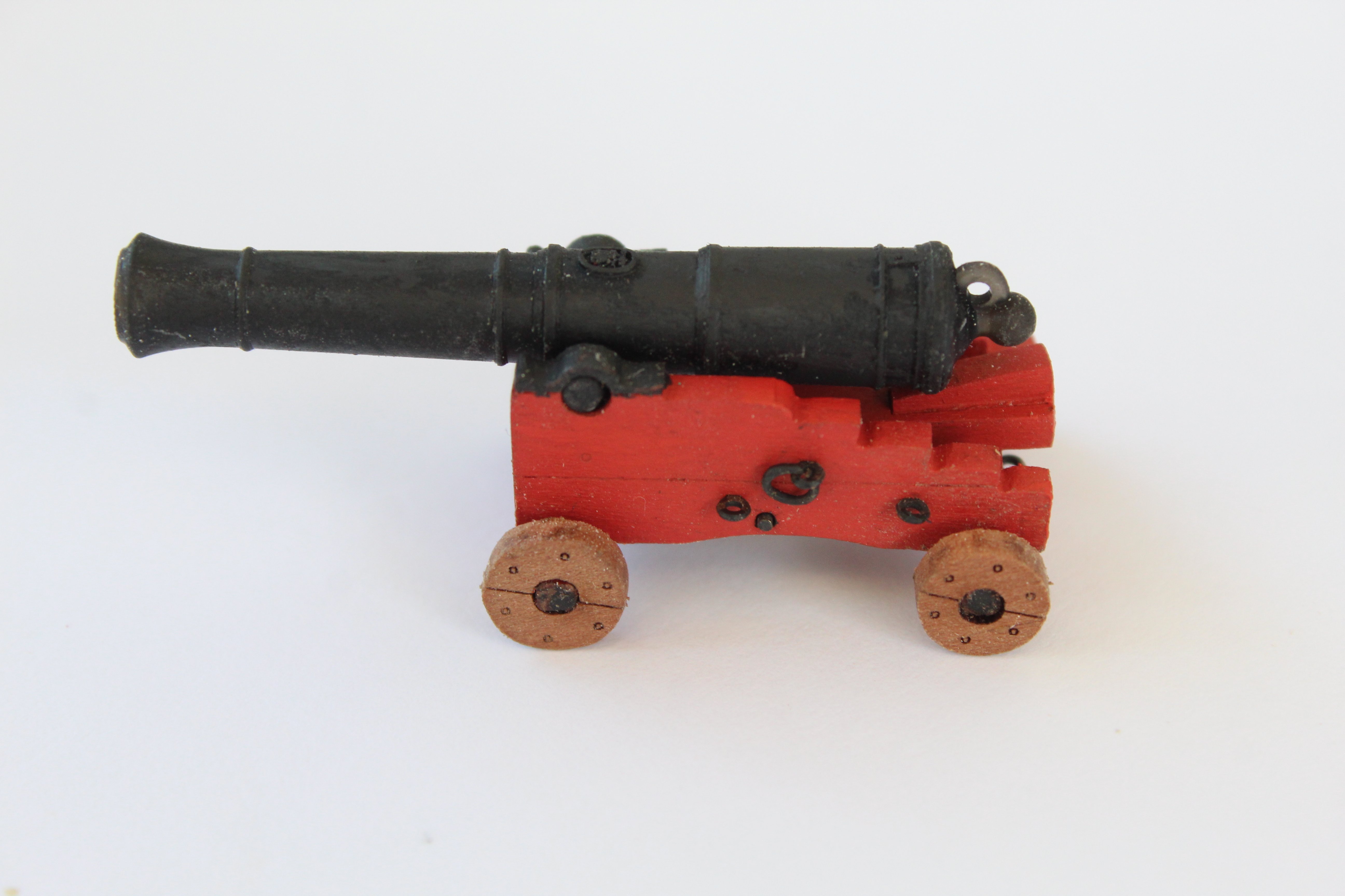
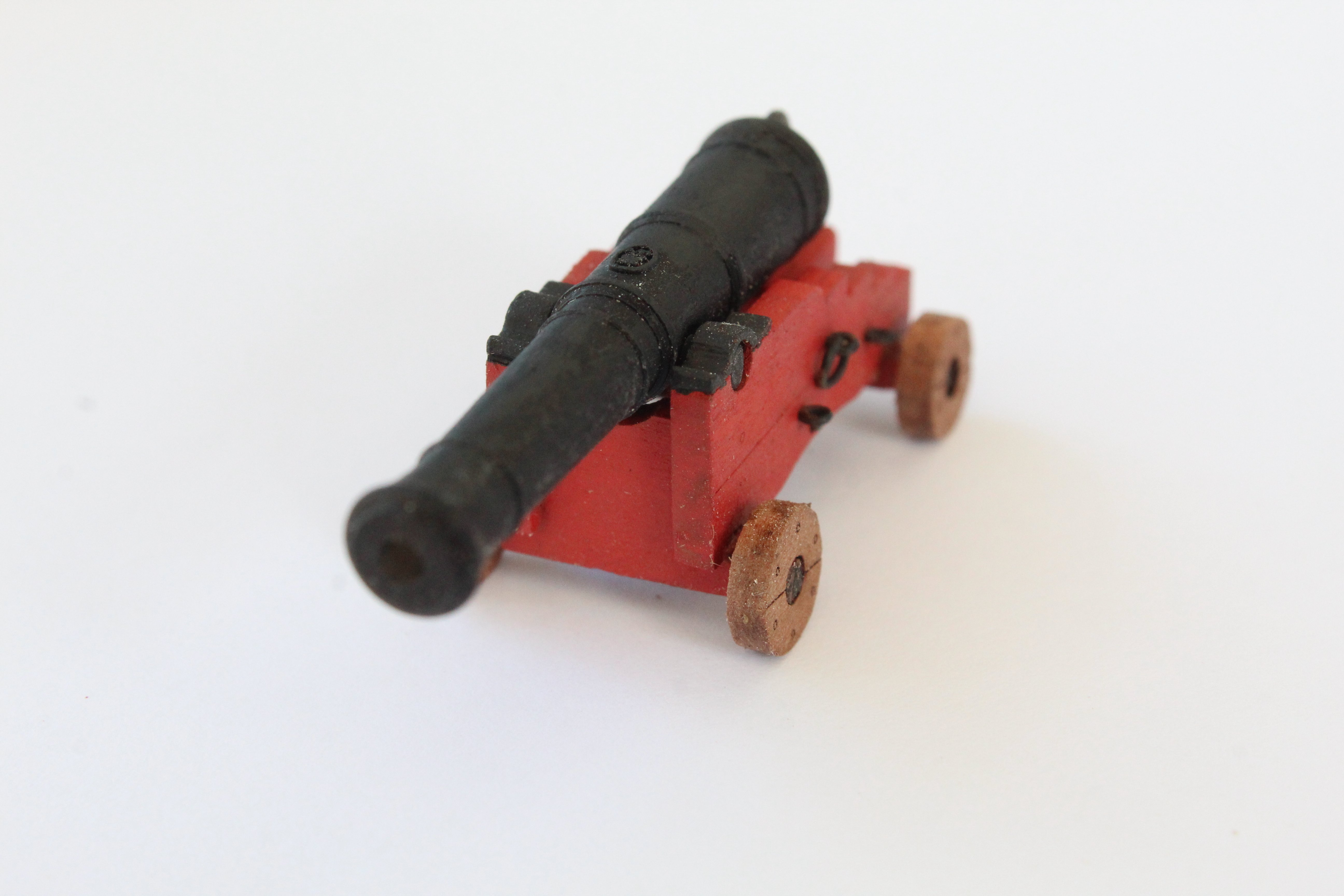
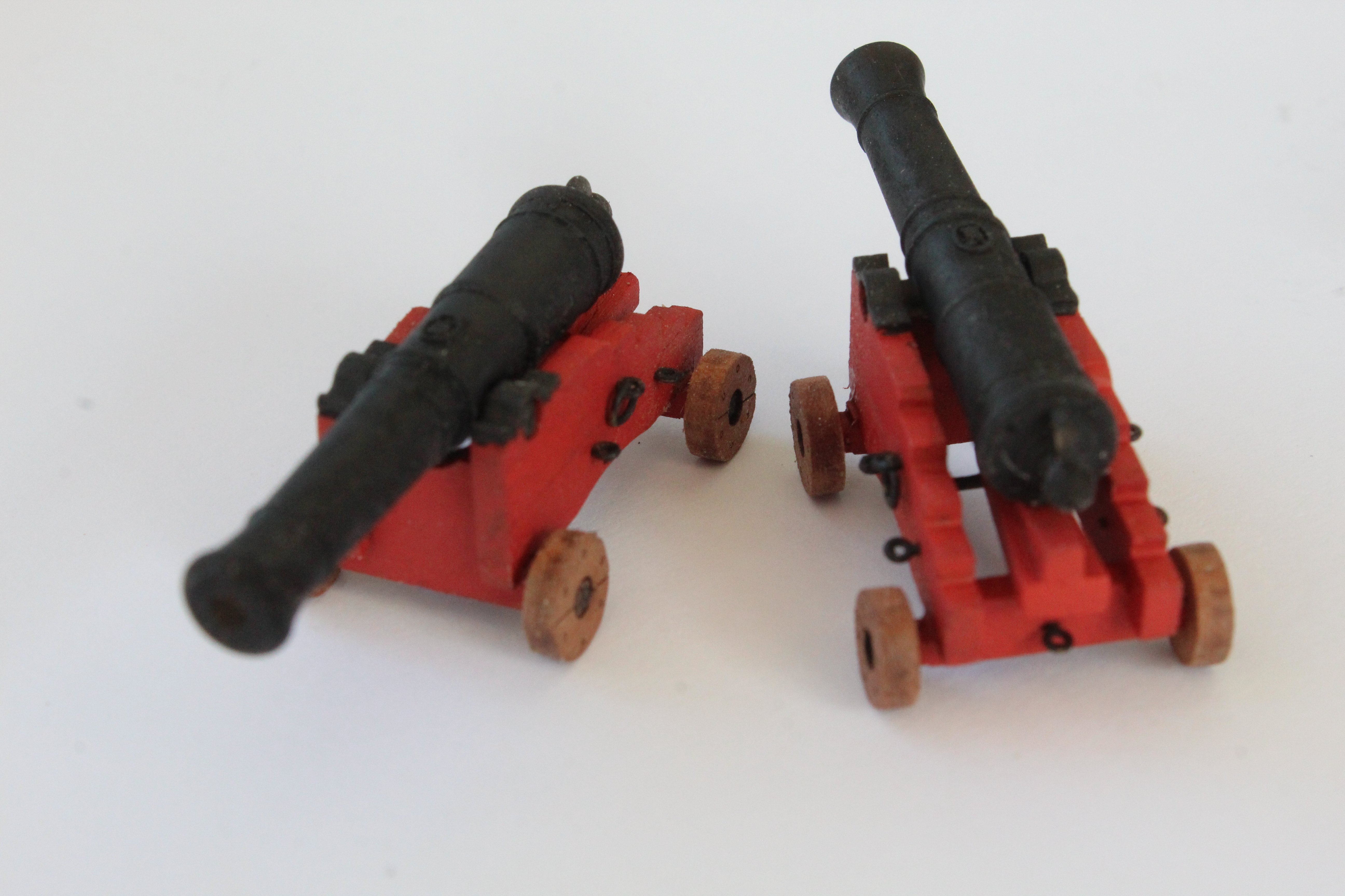
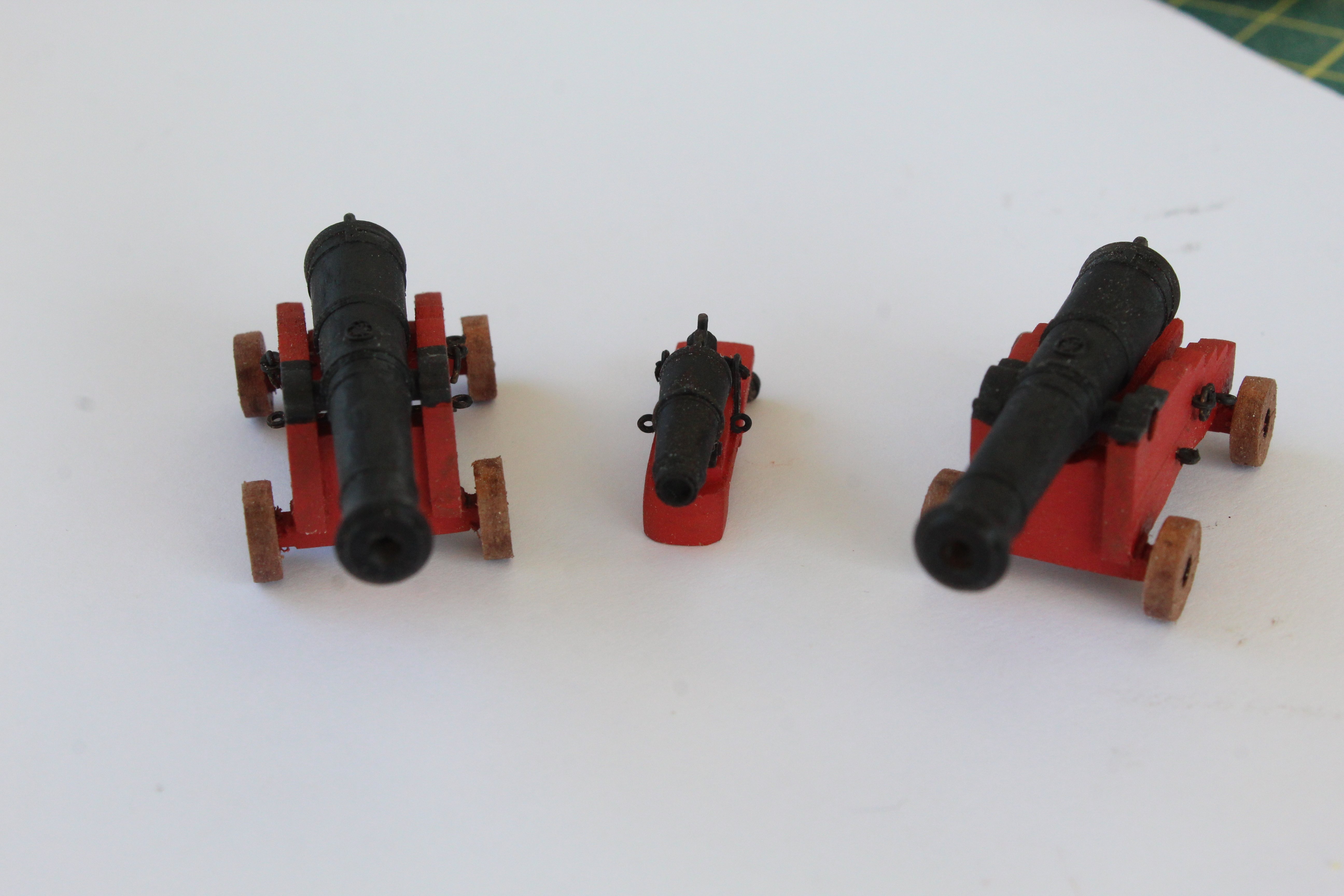
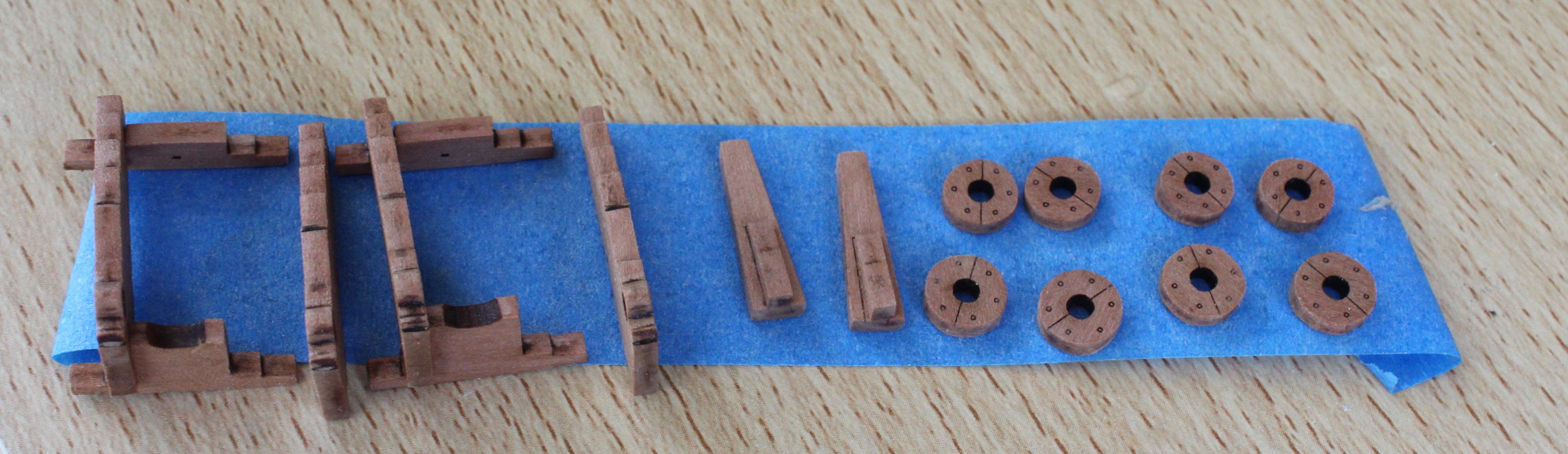
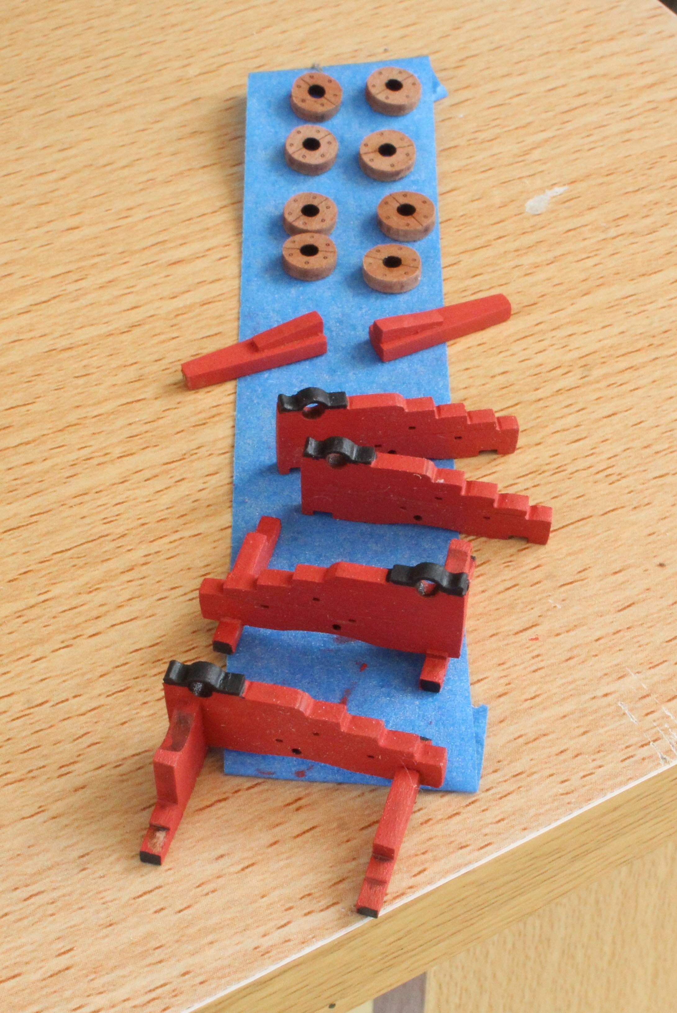
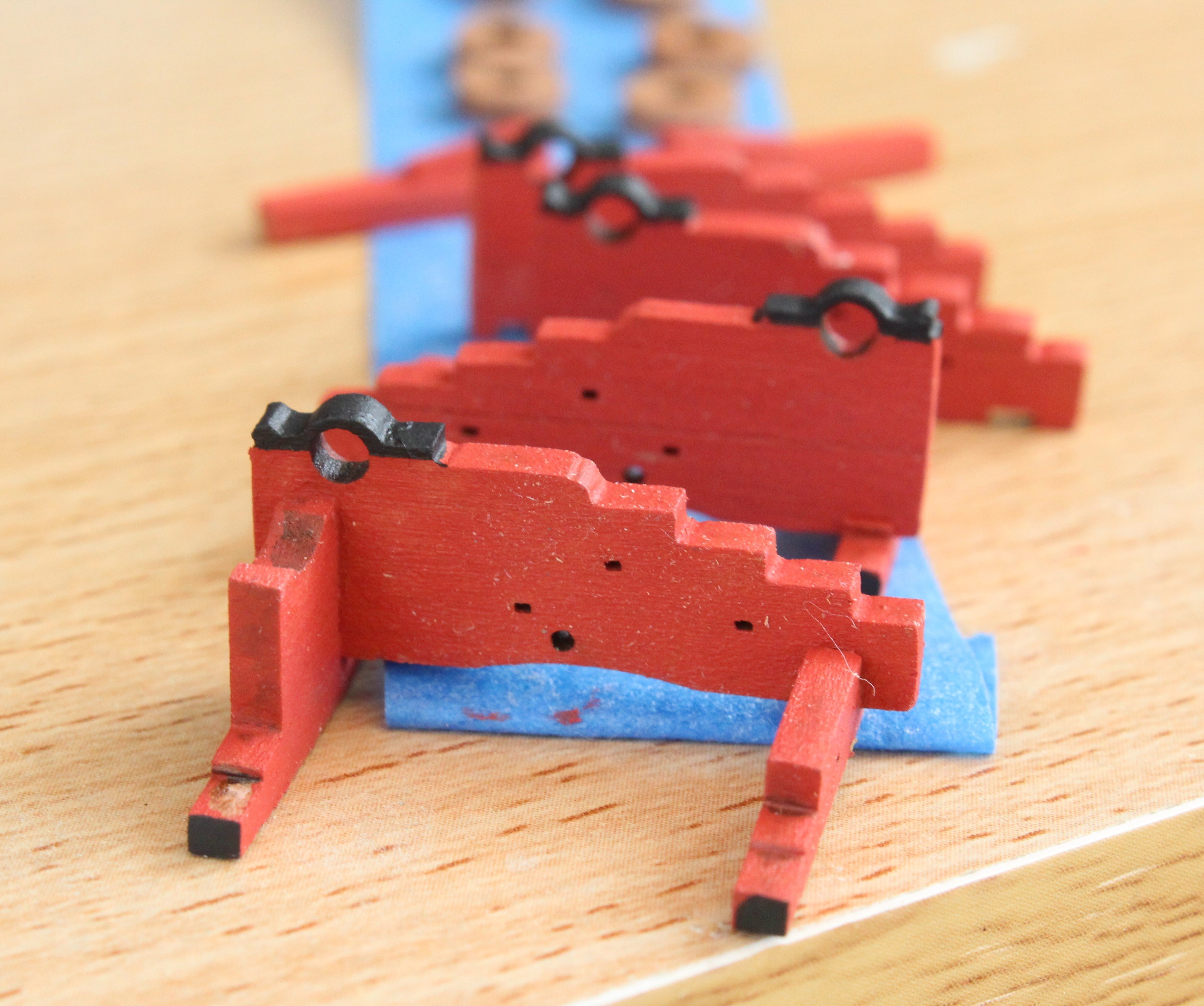
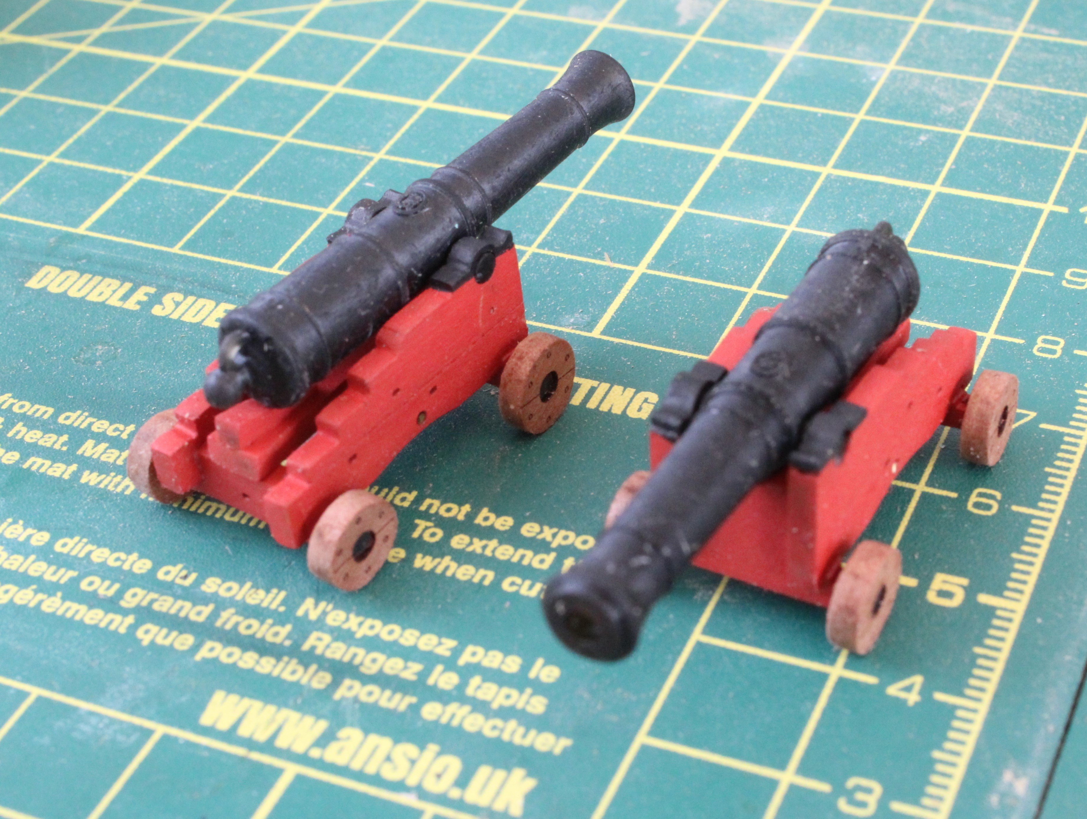
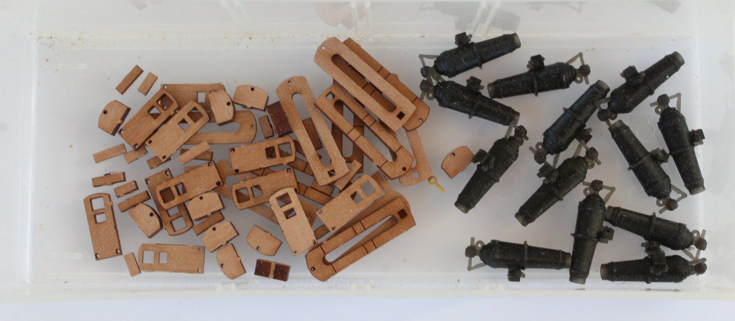
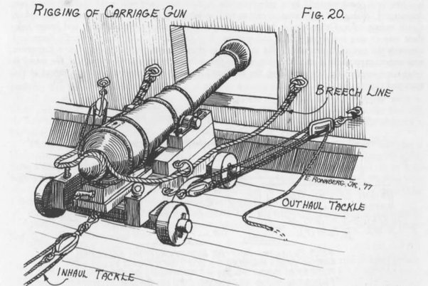
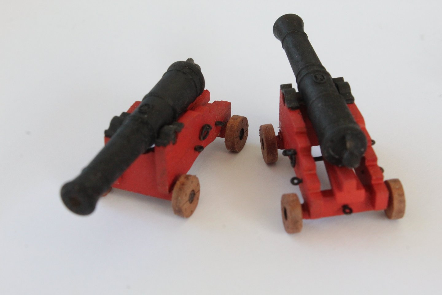
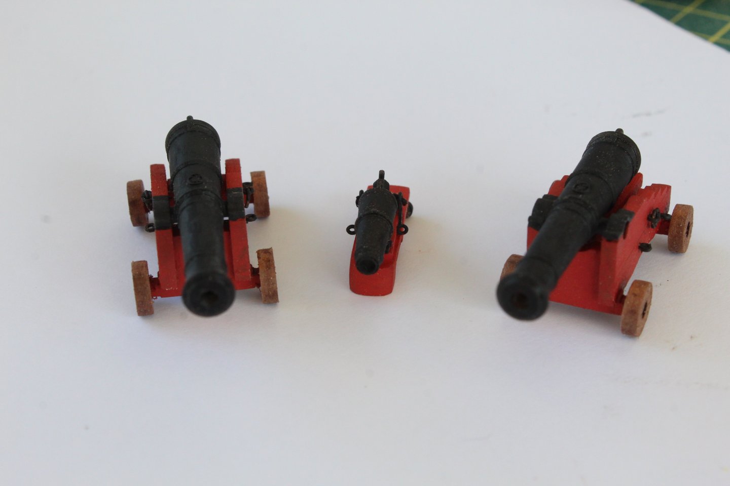
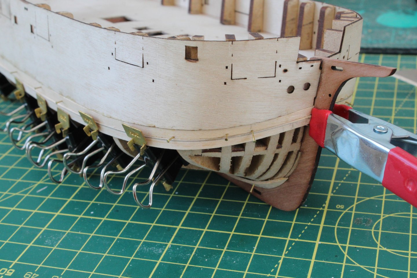
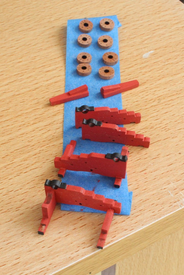
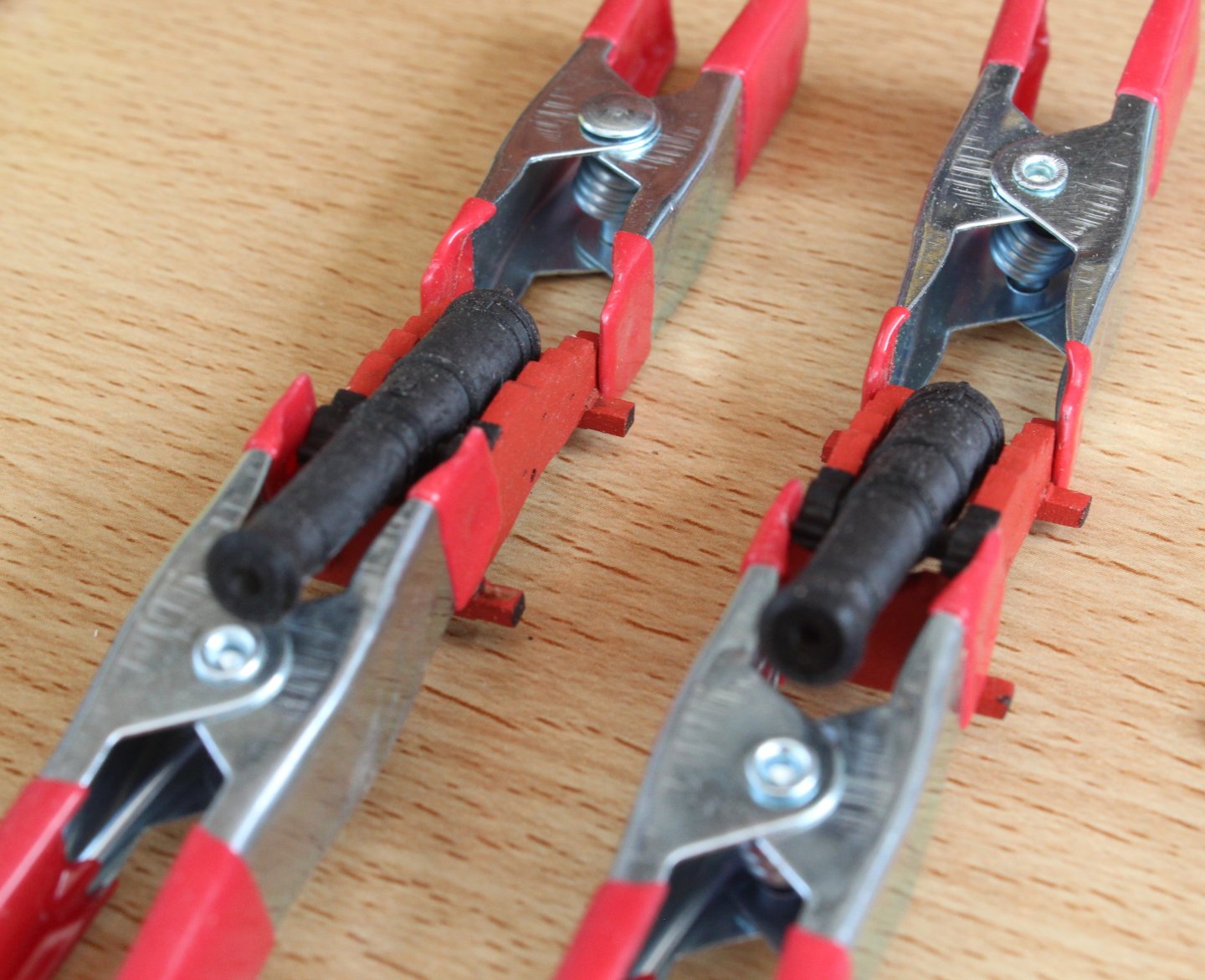
 Build Log Index Date: 23/07/2024 Time worked today: 2 hours. Total time spent on build: 17 hours. Carronades As I was only able to work in the shipyard in fits and starts I thought I would build one of the carronades. The first job was to locate all the PE parts and to chemically blacken them. The process I used, which works really well, is as follows: a) Soak the parts in acetone for a few minutes, agitating them b) Transfer the PE parts to a solution of hot soapy water for a few minutes c) Wash the parts in clean warm water and return to the acetone solution for a few more minutes d) Give the PE parts a final rinse in clean hot water and then place them on a paper towel to dry them e) Place a few parts at a time in some solution to blacken them. I use AK Interactive Metal Burnishing for this task. f) Once blackened the parts are placed on a paper towel to dry off. g) Once dried the parts are place in a container for storage until required. I then painted the framework of the 3D print wheel assemblies flat red. I will touch up / clean as necessary when these parts have been fitted to the carriage frames. All the wooden parts and cannons, required for the assembly, were collected. The carronade assembly process was as follows: a) Remove laser char the various wooden parts b) Glue the wooden parts together. c) Apply a coat of varnish to the wooden assembly d) Brush a couple of coats of flat red painted to the wooden assembly e) Glue the 3D printed wheel to the wooden assembly f) Fit all the PE parts, using super glue. g) Glue the cannon to the carronade carriage assembly. The final task was to add the various PE parts to the two previously assembly cannon assemblies. I opted to add rings to the middle side eyebolts, which are used for the breech line. I am hoping to have some time to sand the hull tomorrow, but as we travel to Budapest on Thursday for a river cruise visiting places along the Danube, including, Bratislava, Vienna and Salzburg, I might have to put that task on the back burner until we return home.
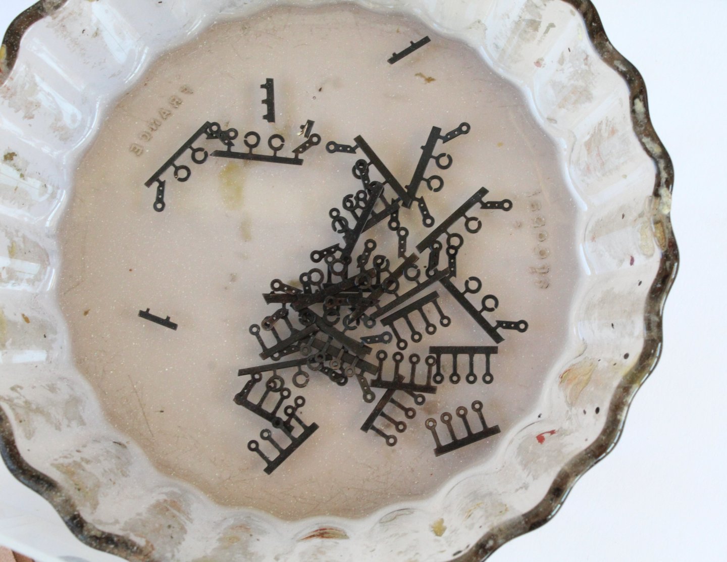


-
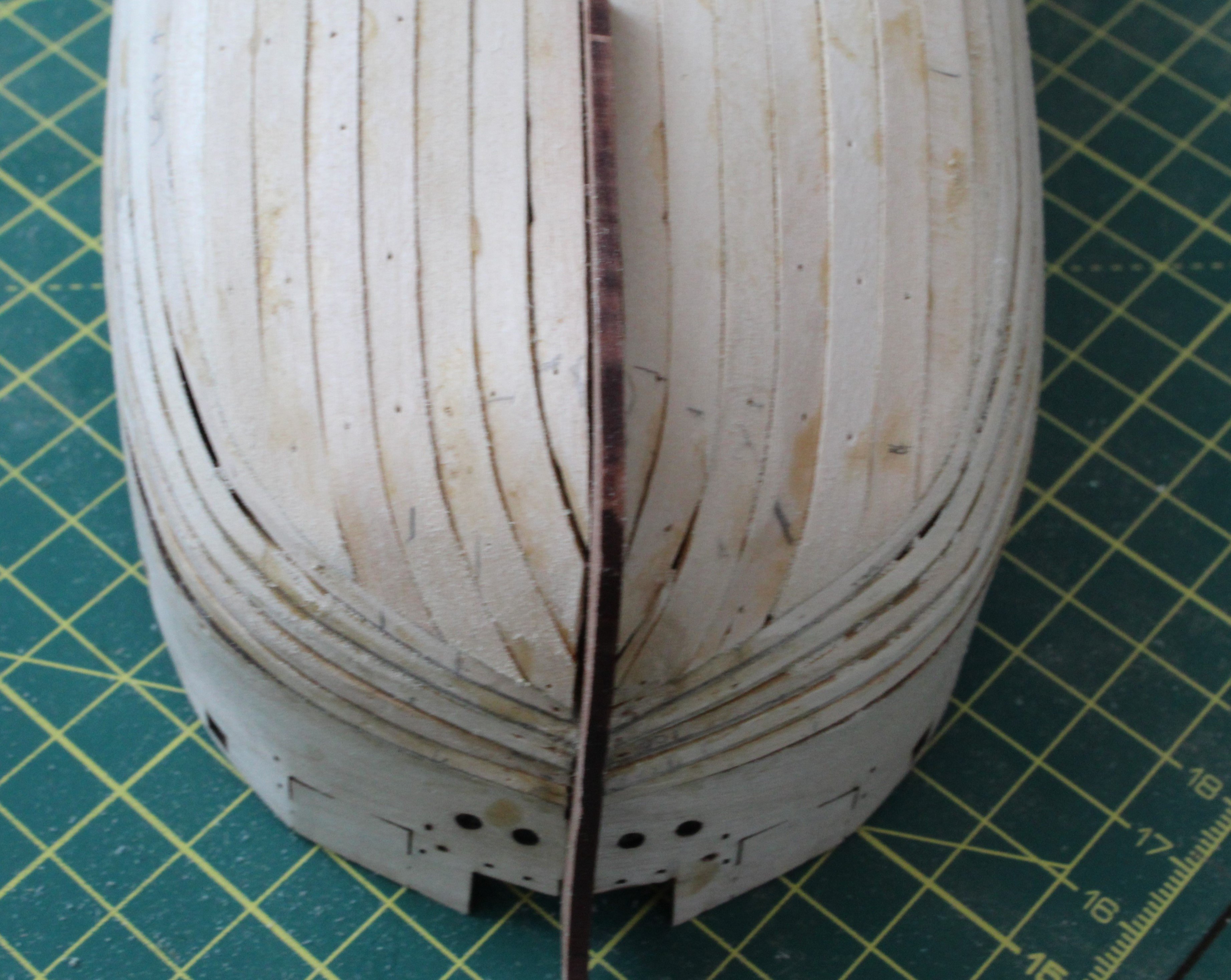
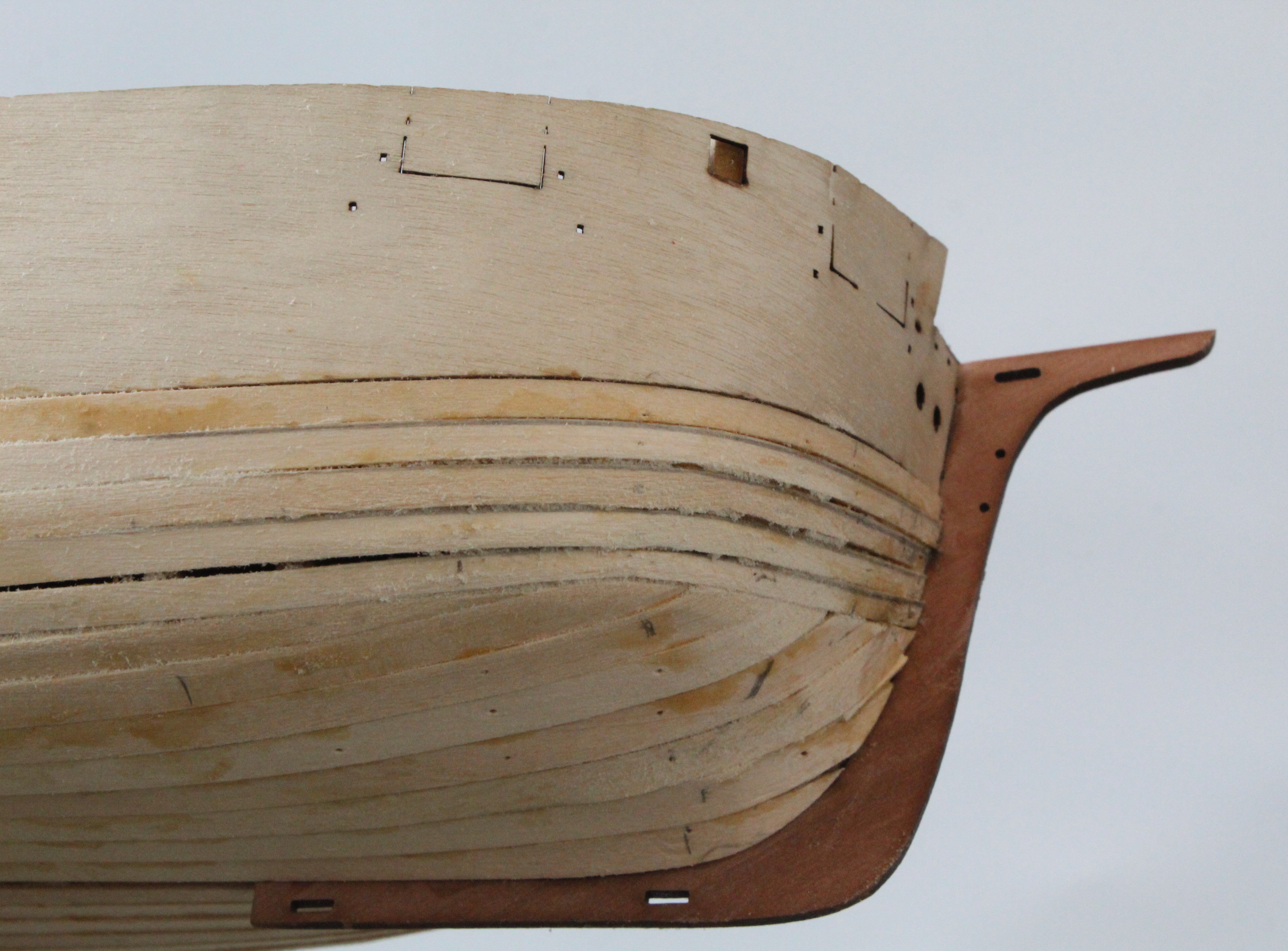
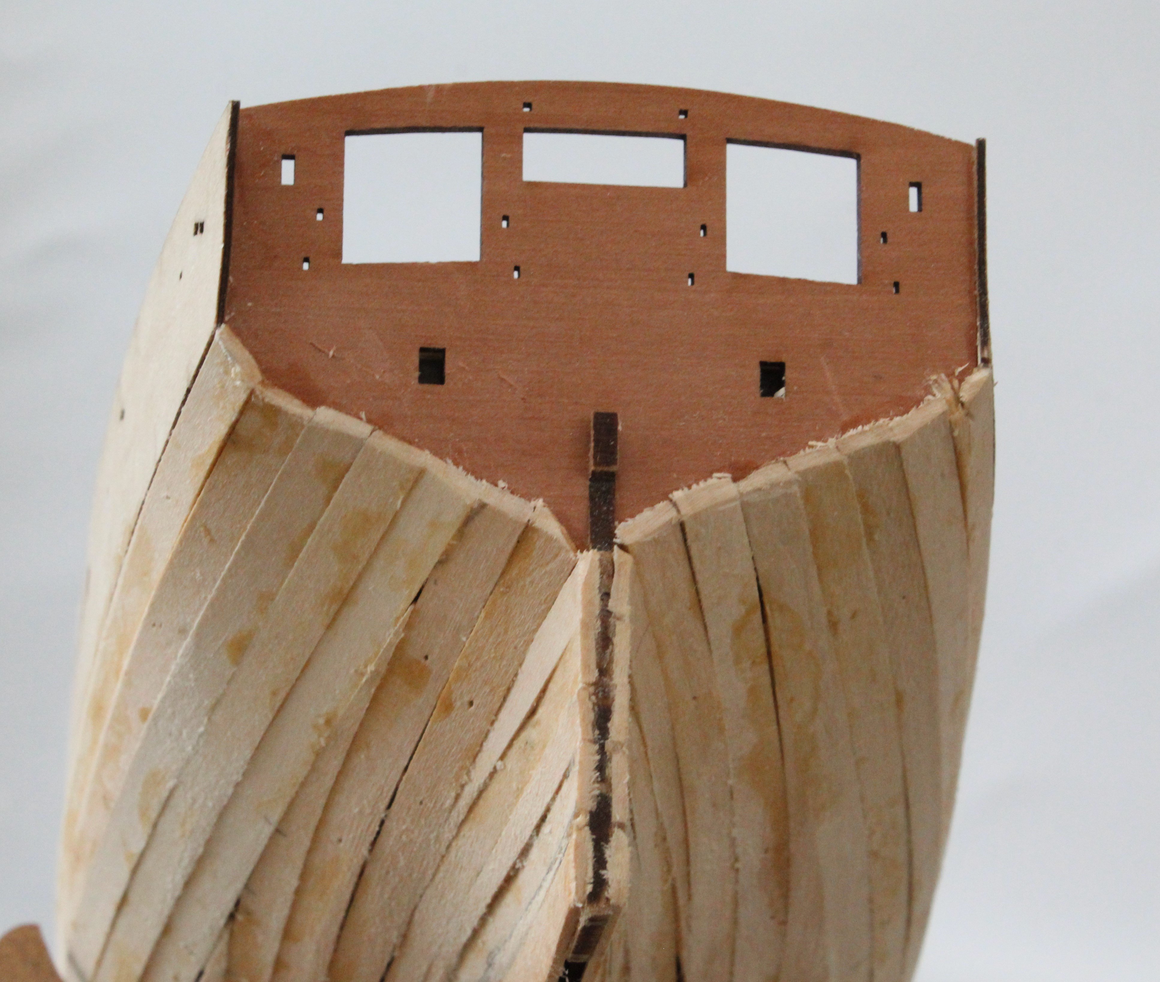
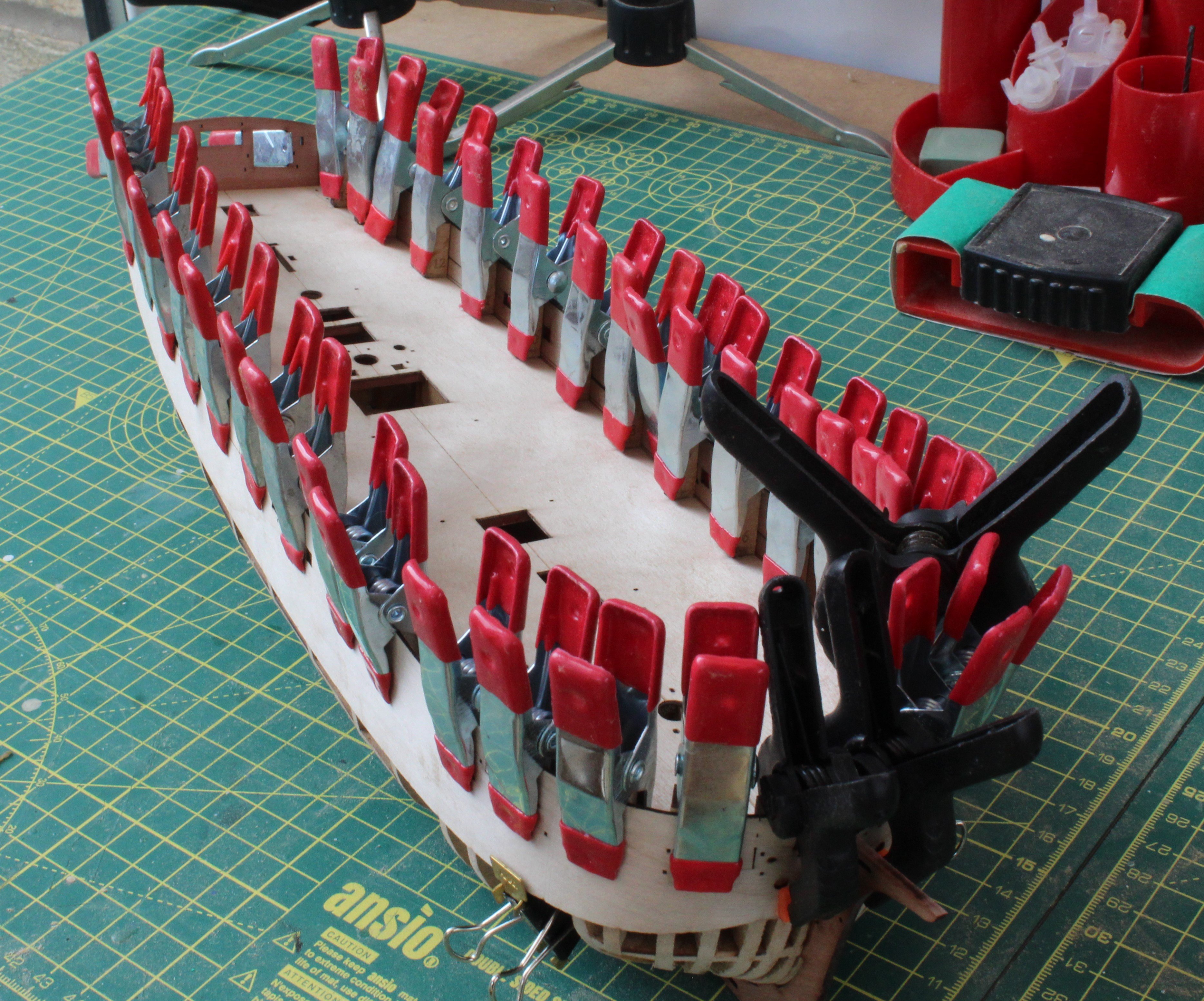
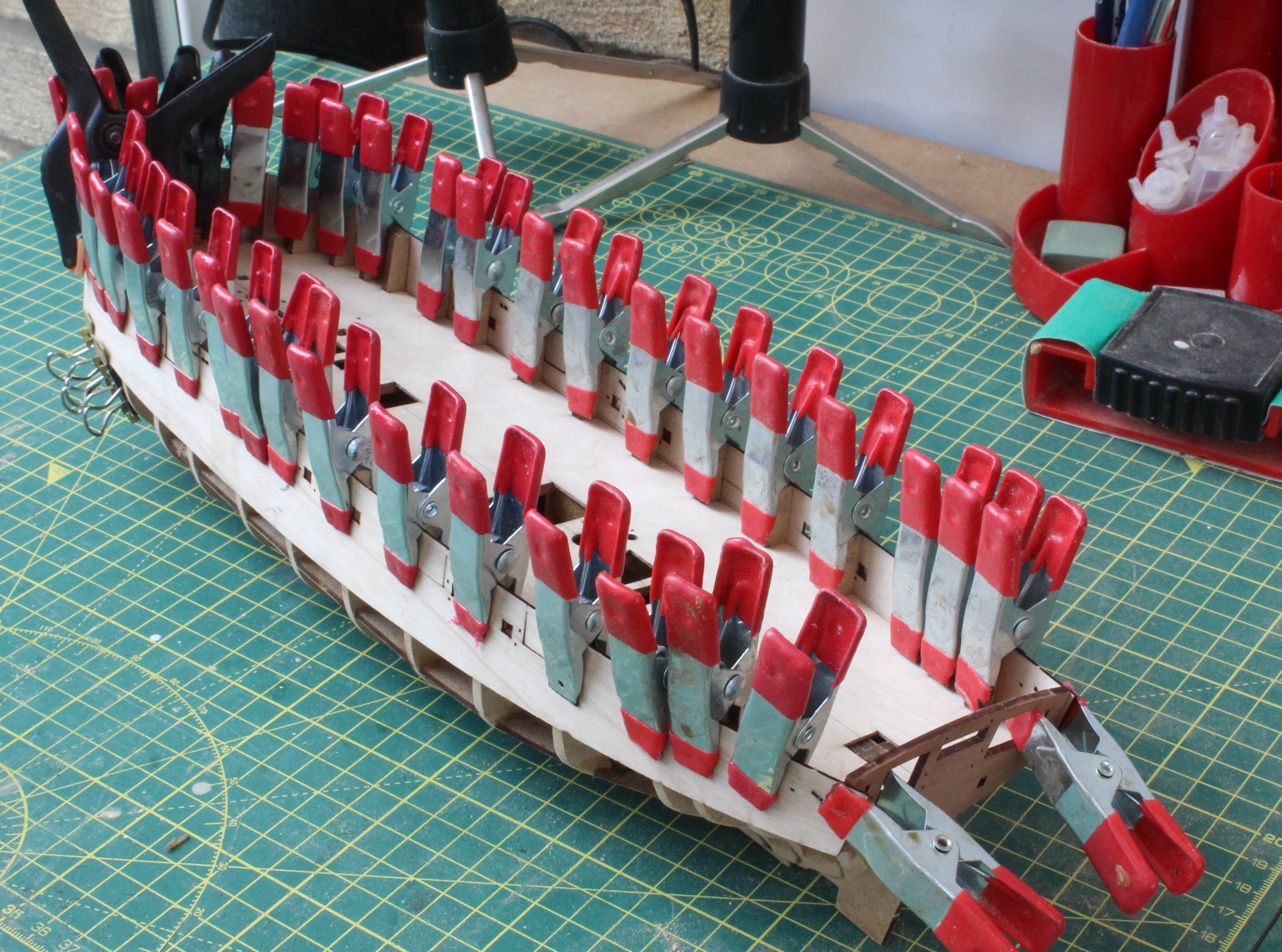
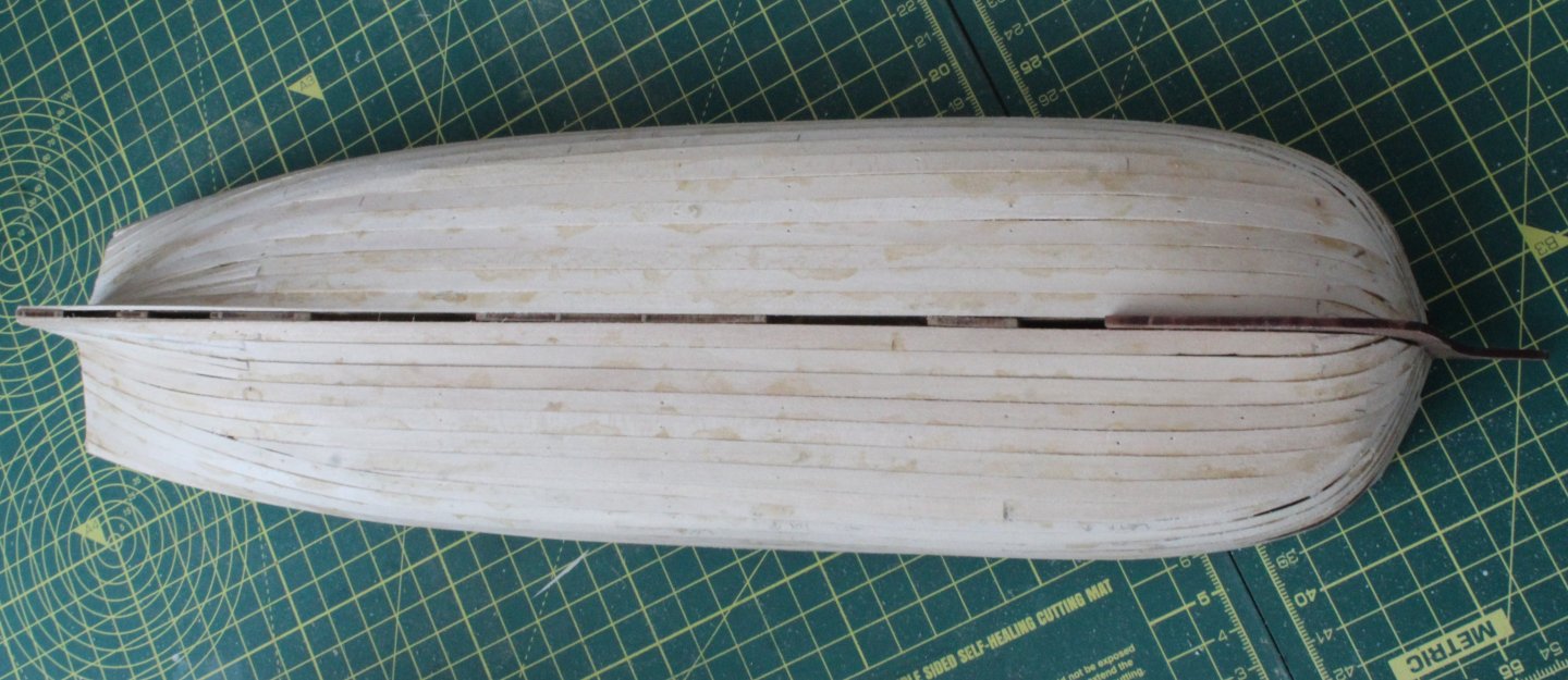
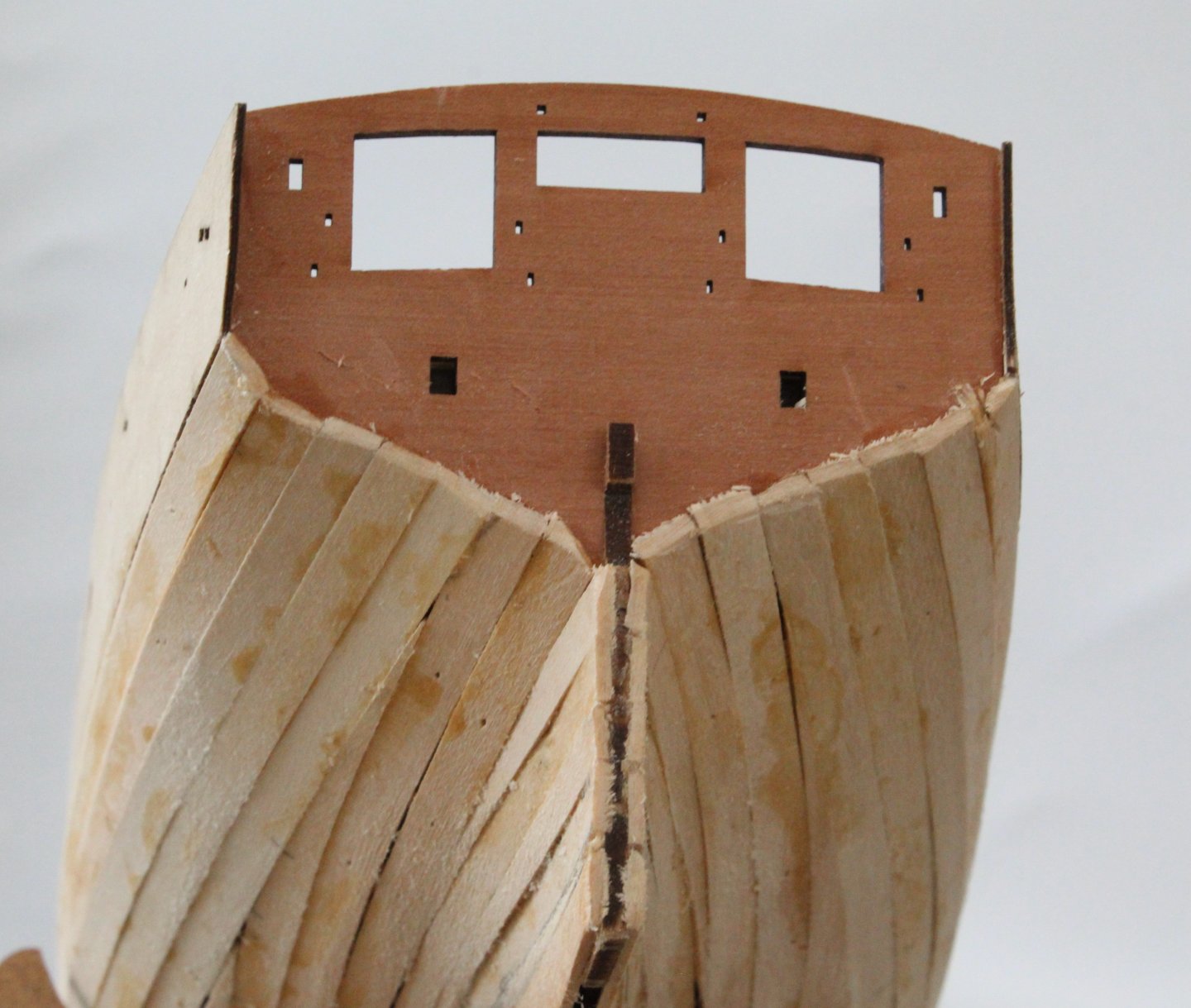
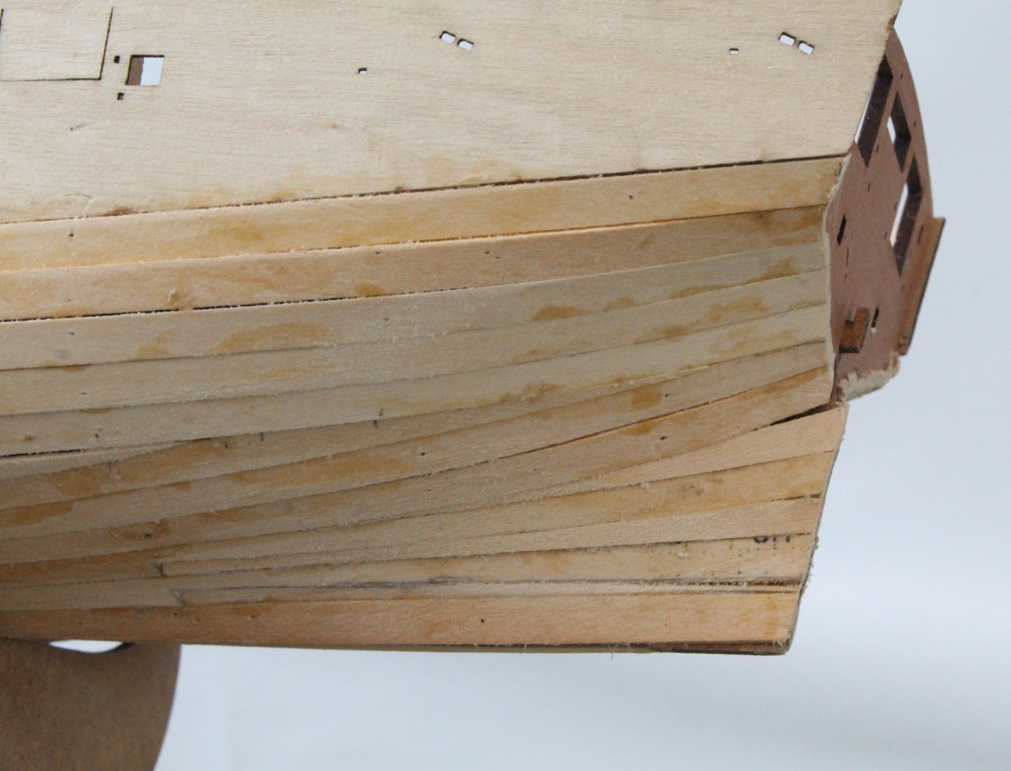
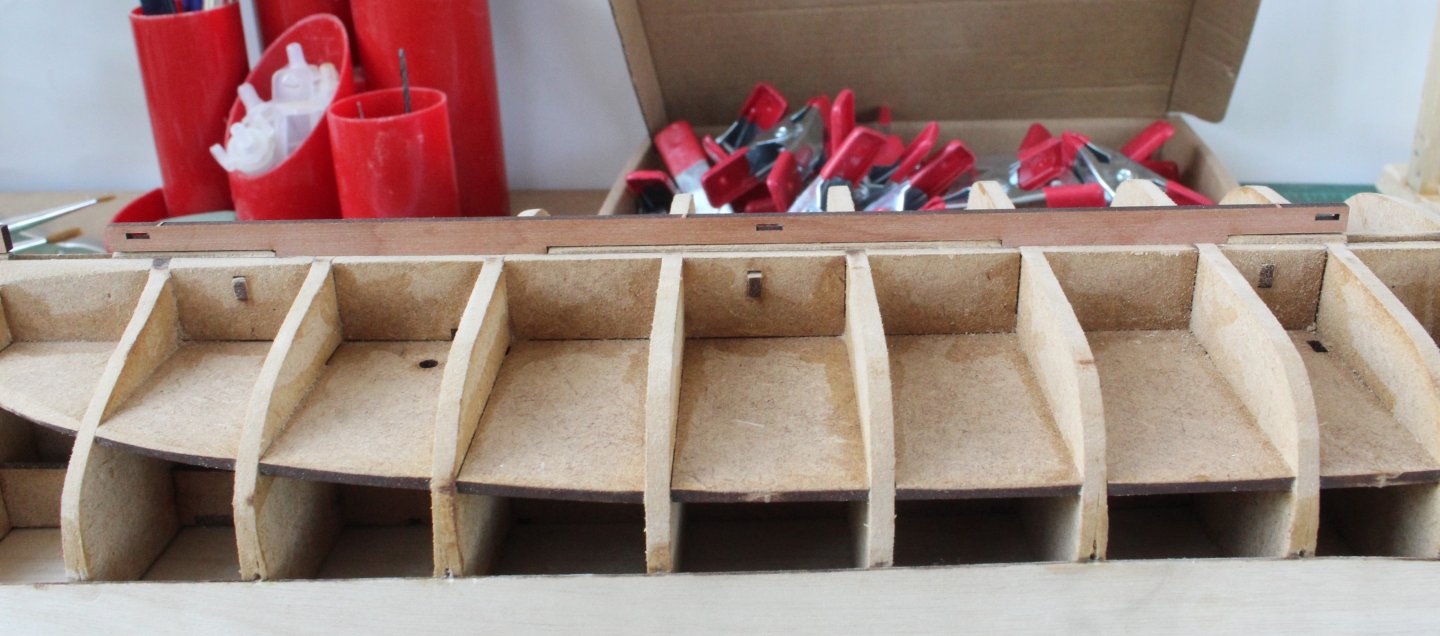
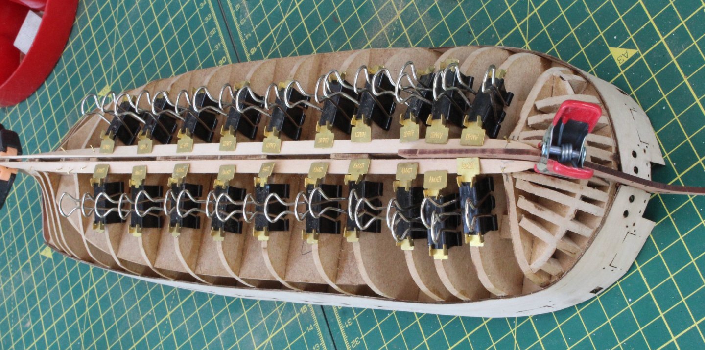
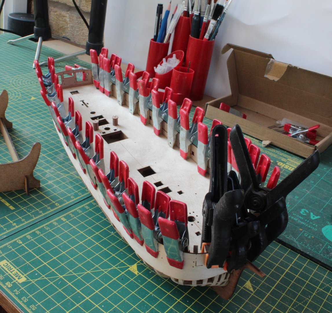
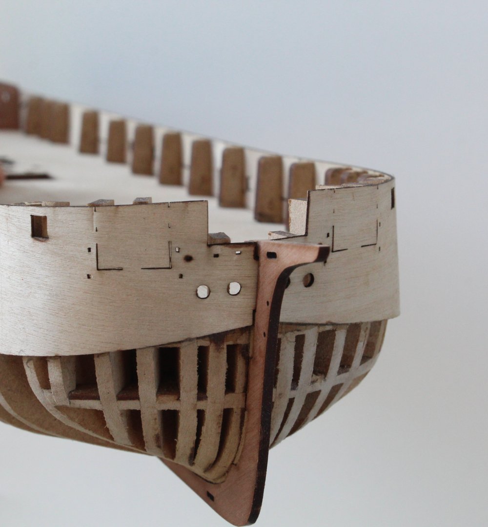
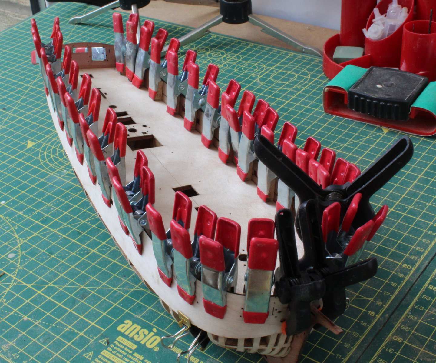
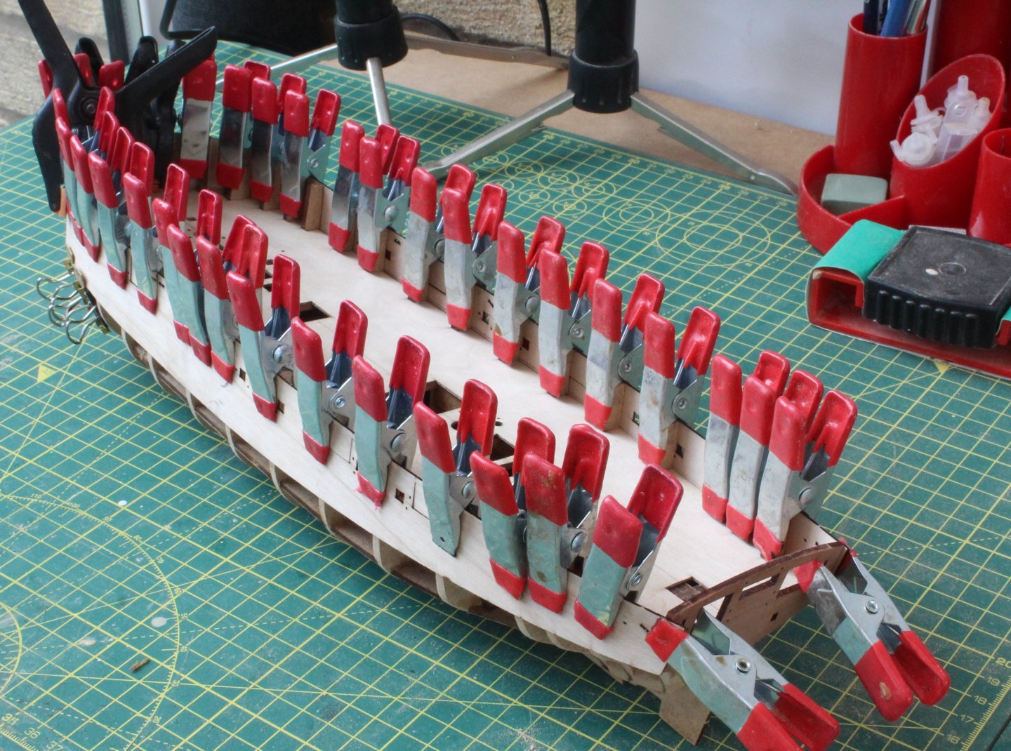
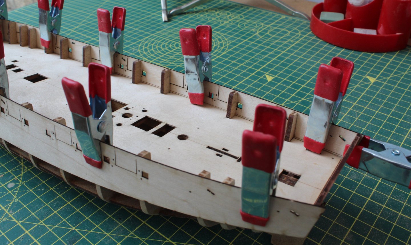
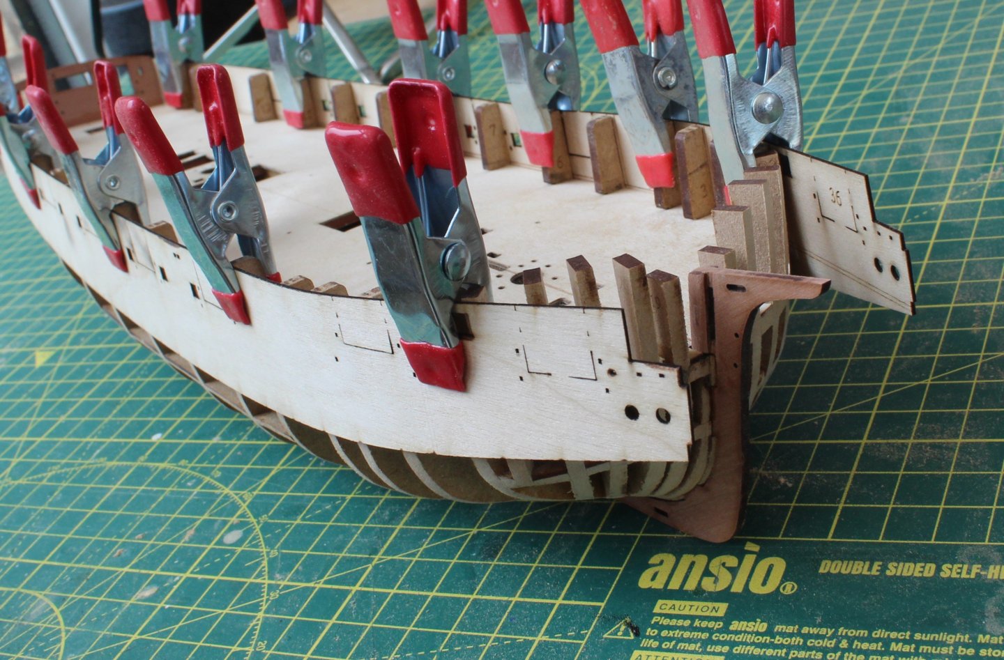
Build Log Index Date: 22/07/2024 Time worked today: 4 hours. Total time spent on build: 15 hours. First Planking With reference to my last post regarding how not to add a stealer, I have actually managed install the stealer correctly. I added planks in pairs, working in both directions (top to bottom and bottom to top). When adding the upper planks it would have been much better and neater if I applied a lateral bend to the planks. Given this is a relatively small hull and the planking will be sanded smooth (and any gaps filled) and covered with a second layer I decided not to use using lateral bends for this layer. By working in both directions, I ended up abandoning tapering the planks at the bow when working from keel upwards. As can be seen in the attached photo’s the first planking layer is not my finest work. The purpose of the 1st planking is to create a solid base and once this planking layer has been sanded smooth it will be ready for the 2nd planking layer. I will use lateral plank bends when adding the 2nd planking layer to ensure I get a much neater finish. I also need to trim the excess bulwark material from the stern area as can be seen in the next photo.


-
Thank you
-
Hi Dan Definitely should be two eyebolts on the each platform and the K block is secured to an eyebolt. There are holes provided on parts 75 and 78 for these eyebolts so there should be no need to drill. I normally seize blocks to eyebolts before fitting them to ship. Hope that helps Glenn
- 146 replies
-
- 3
-

-
- Adder
- Vanguard Models
- (and 1 more)
-
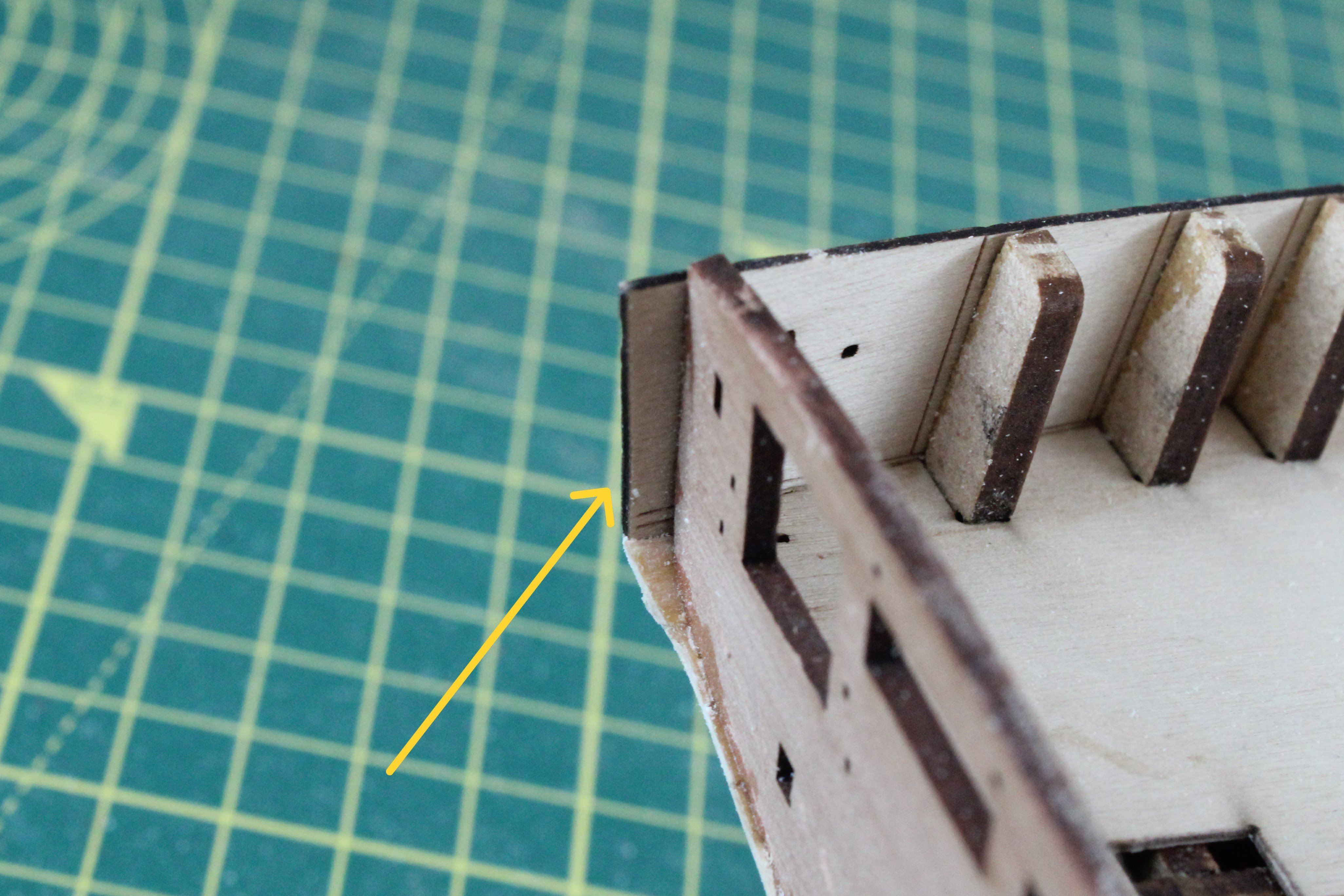
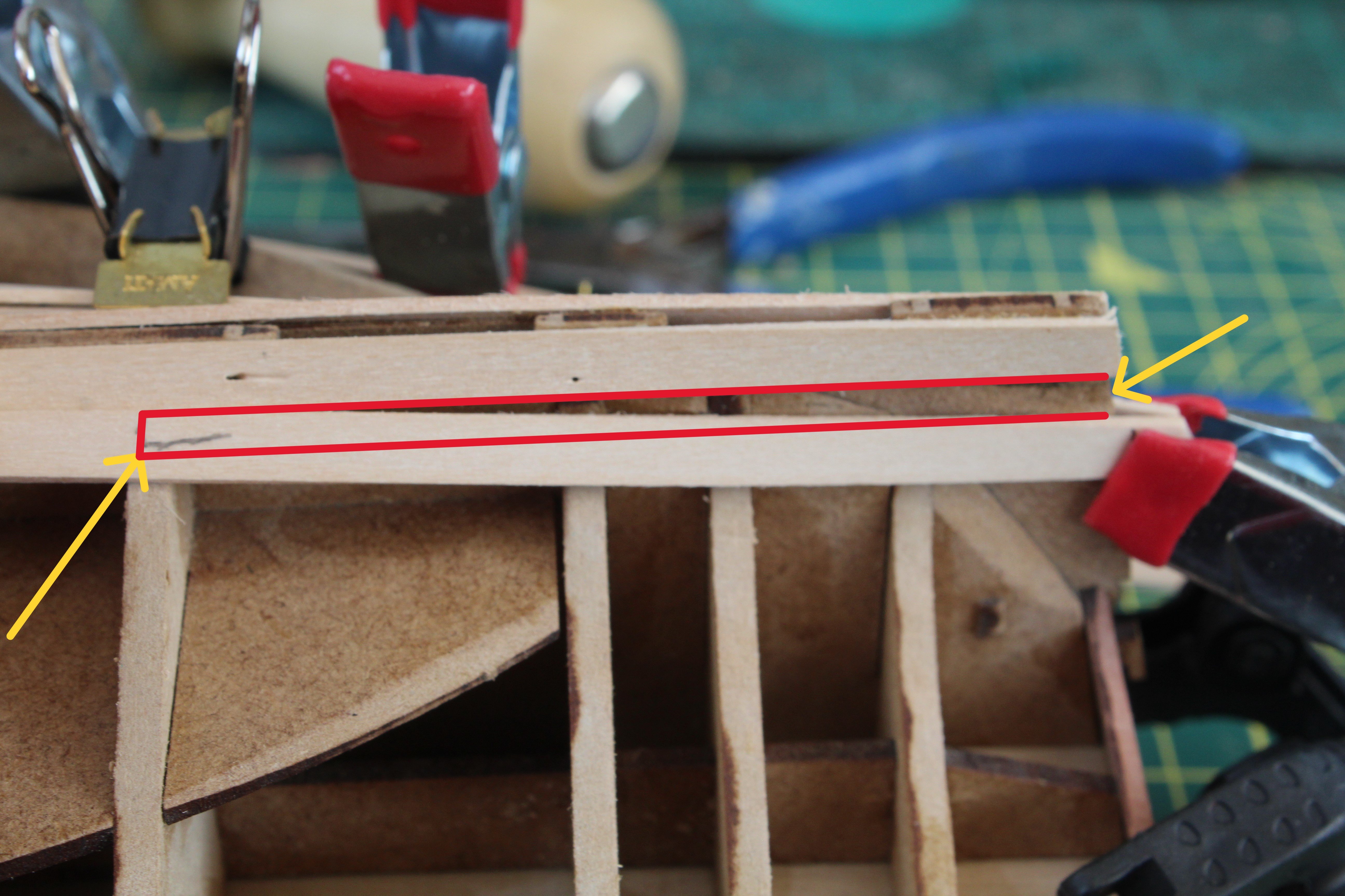
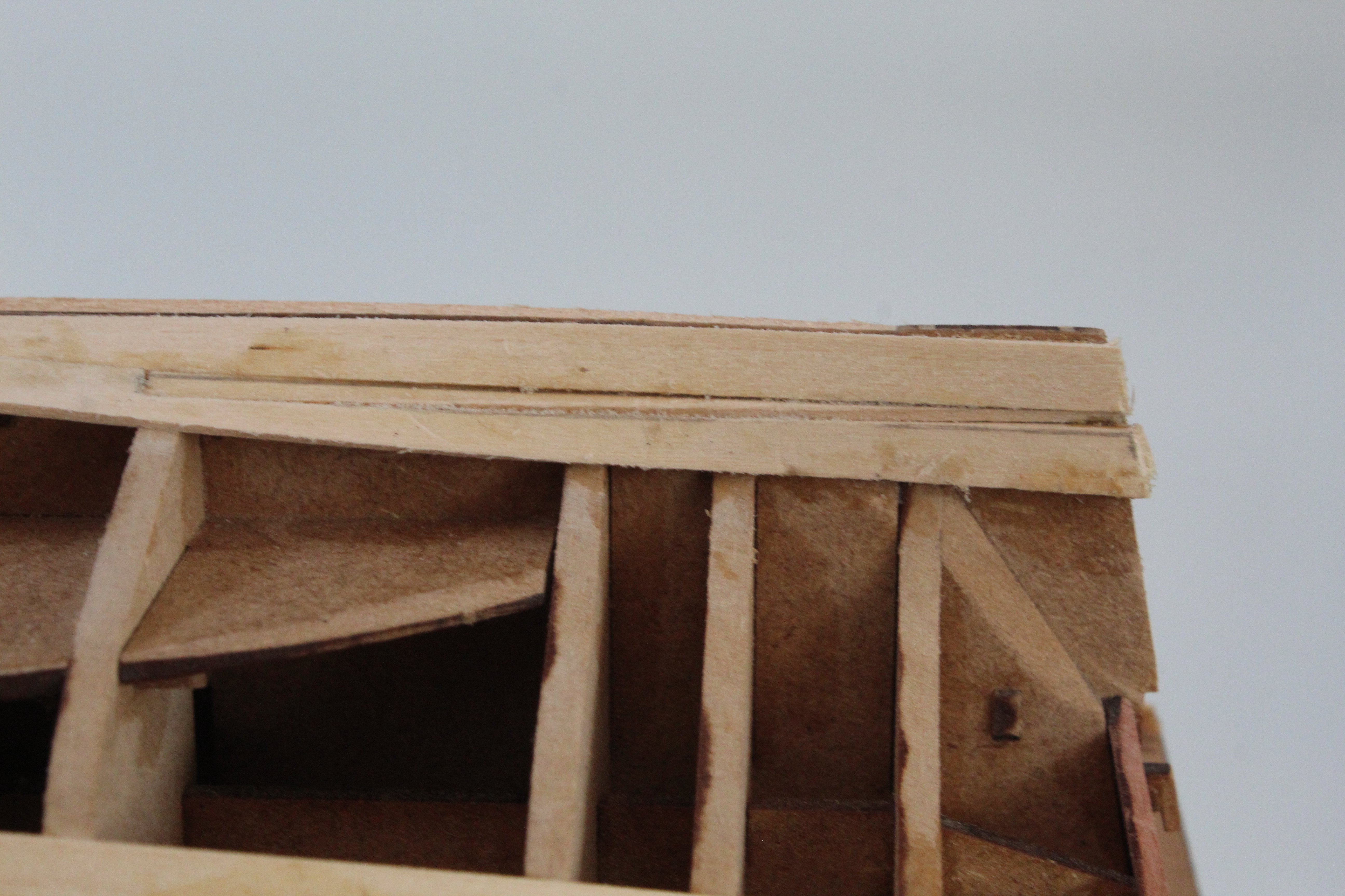
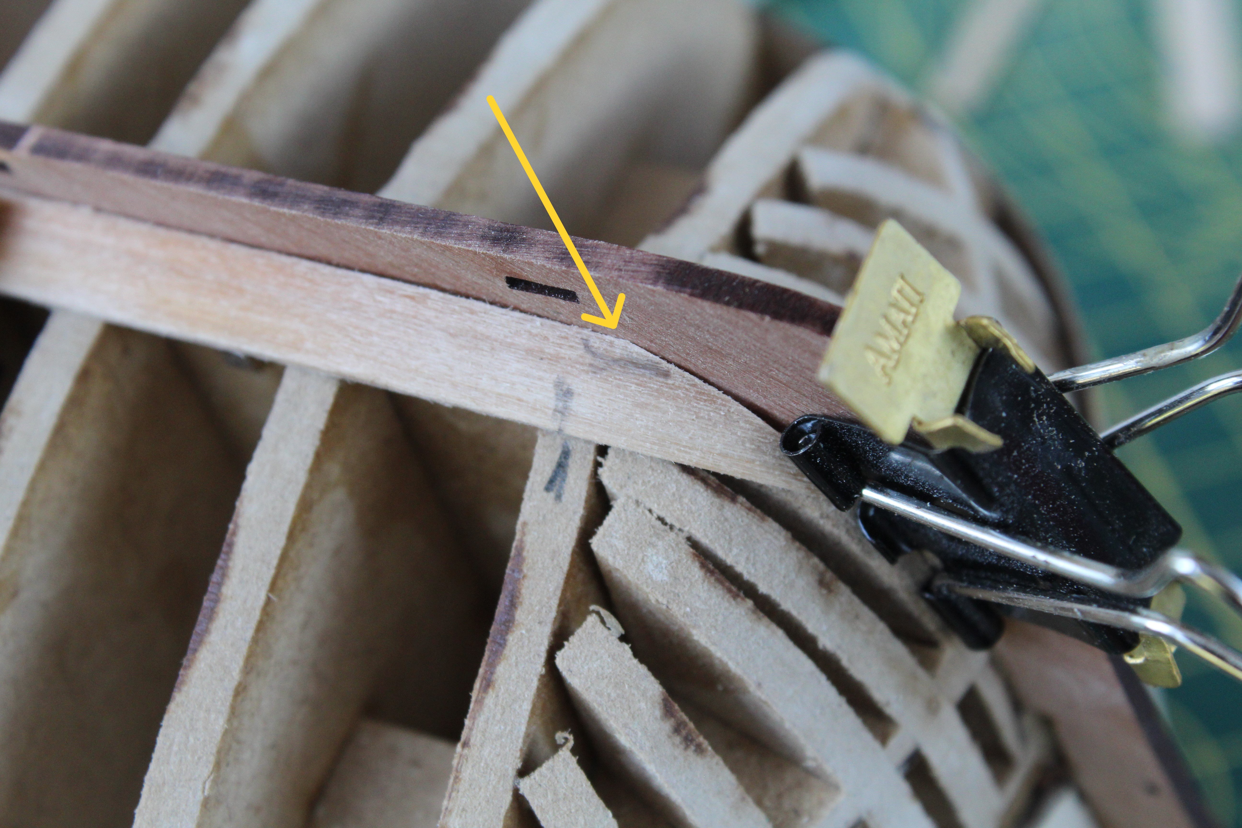
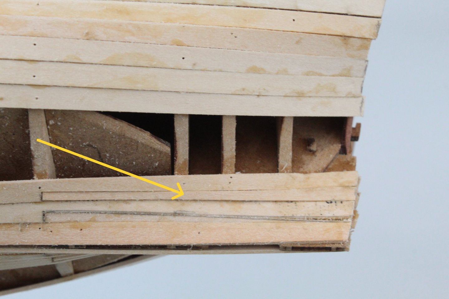
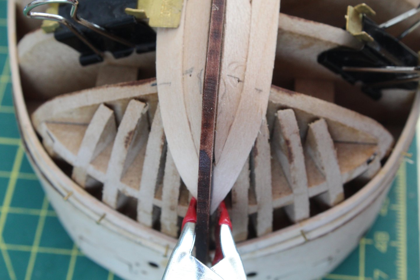
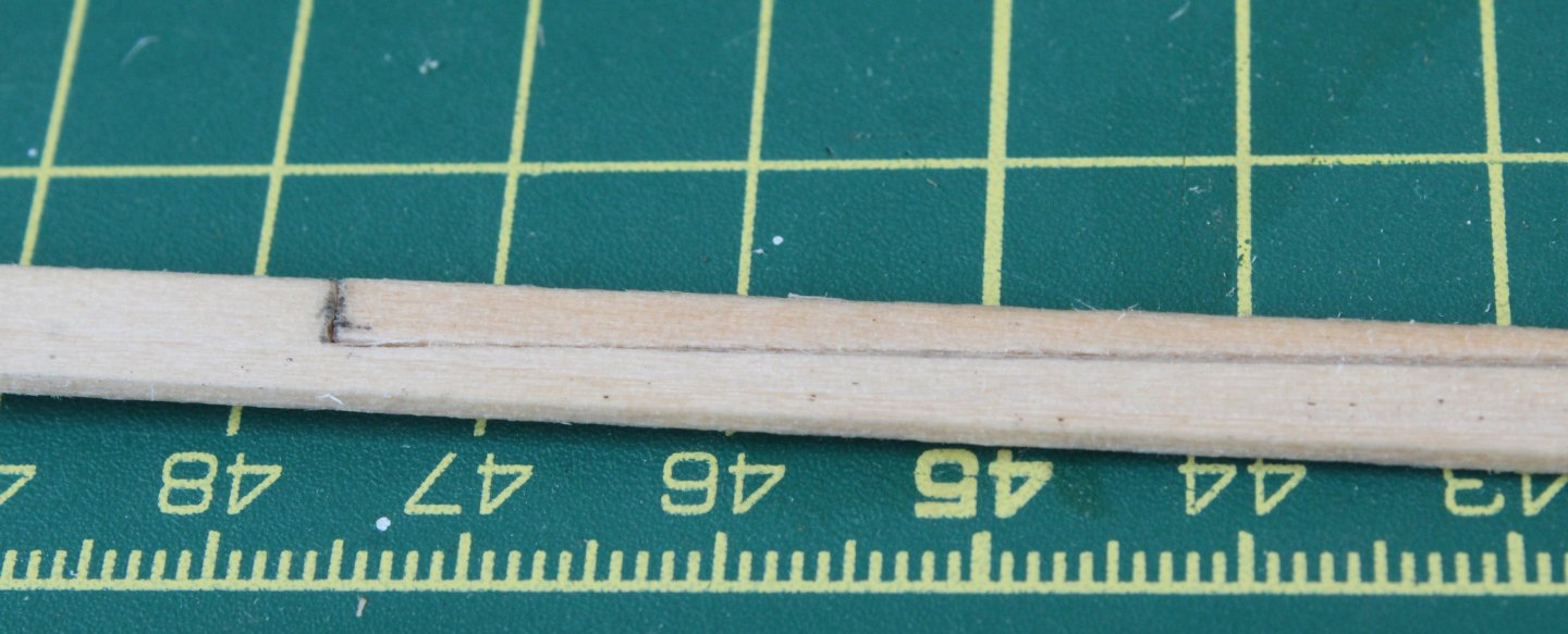
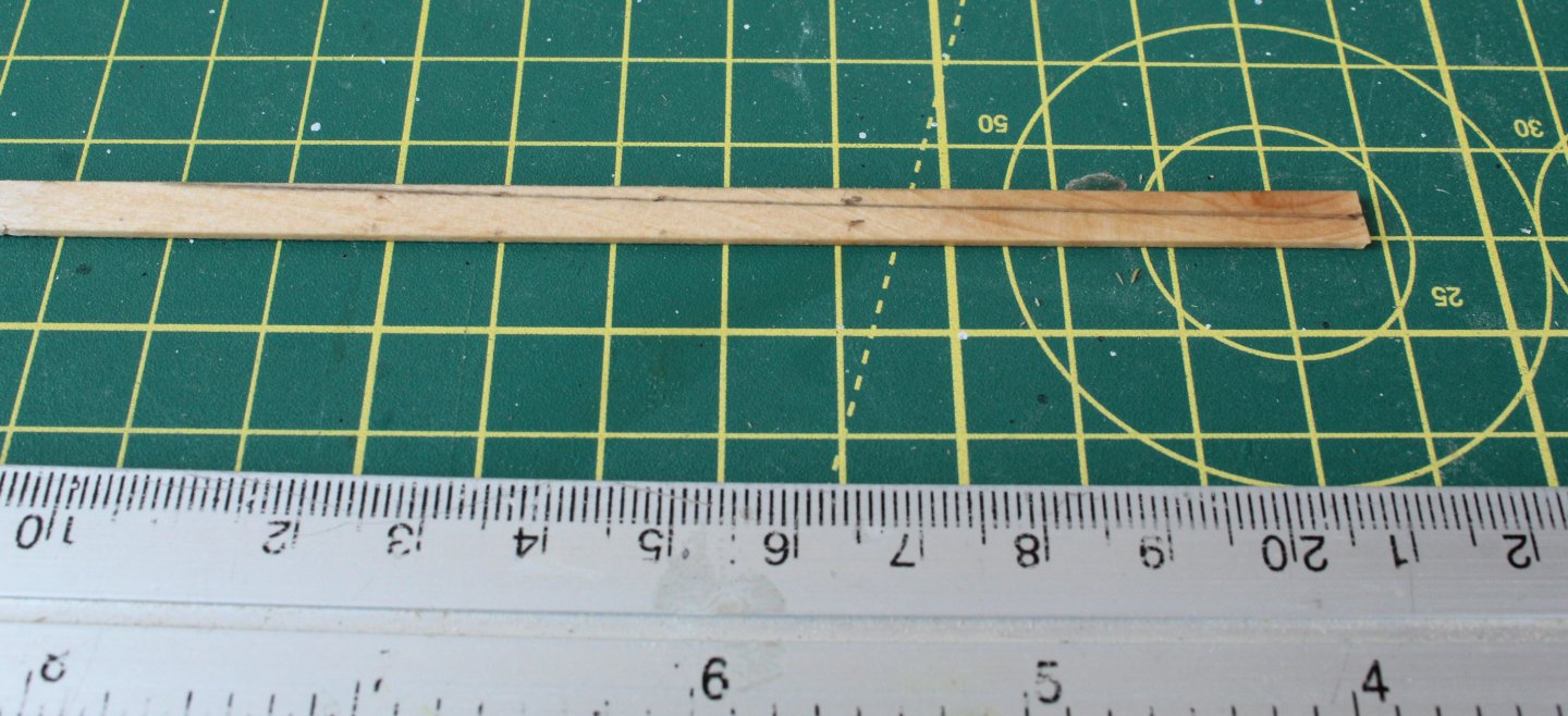
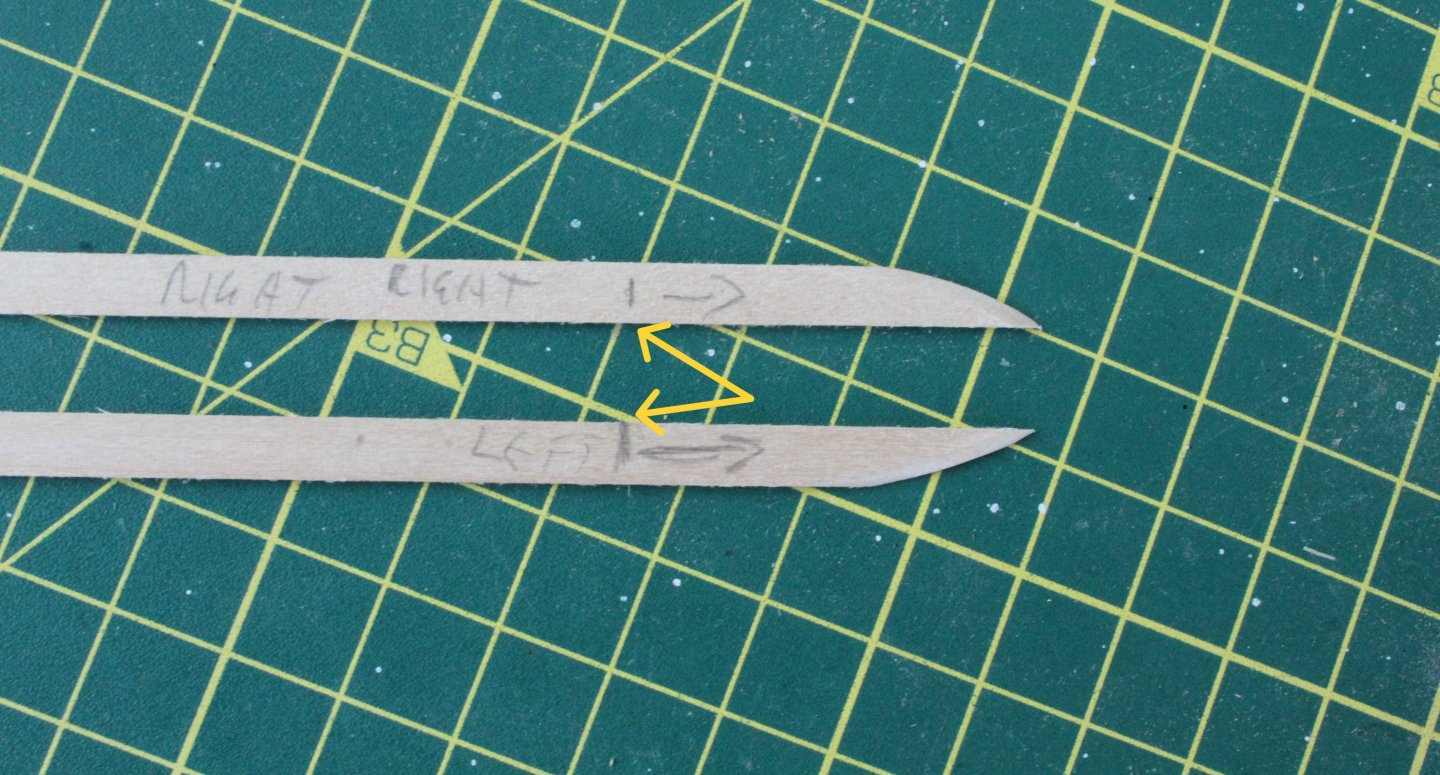
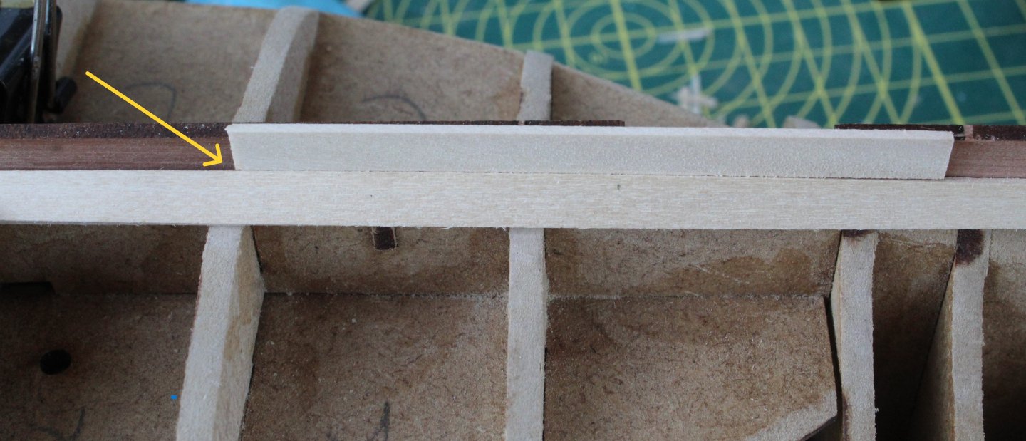
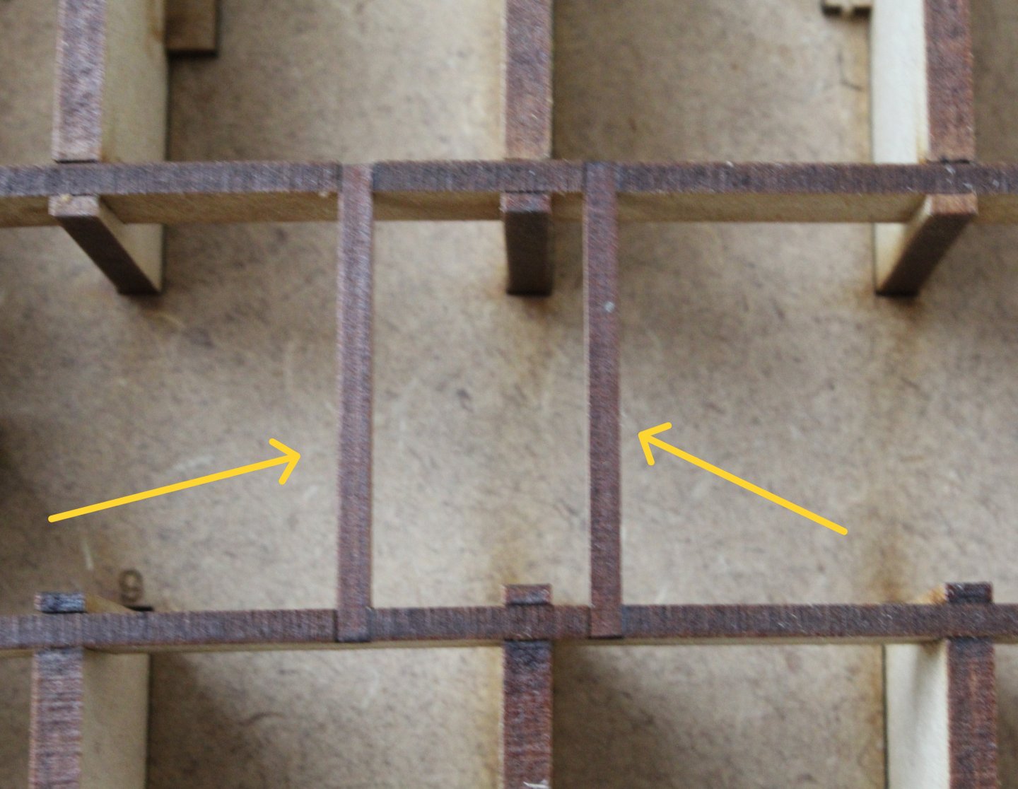
Build Log Index Date: 20/07/2024 Time worked today: 1 hour. Total time spent on build: 11 hours. How Not To Fit A Stealer I was planning to detail how I fitted a stealer. Halfway through the process I had a brain fart and made a schoolboy error. As I ran the next plank lower plank I felt the natural flow of the plank is as shown in the photo below and will require a stealer to fill the gap. The plan was to make a stealer as shown by the red outline. The yellow left-hand arrow shows where the stealer will sit over a bulkhead and will be 2.5mm wide (half a plank width). The yellow right-hand arrow shows the stern post area where the gap is a full plank width gap (5mm). I carefully marked the plank and the stealer. So far so good. After making the stealer I was happy with how it interlocked with the plank, before fitting. I did not notice my error. I was really pleased with how it looked once the plank and stealer were glued in place. The more eagle eyed of you will notice my brain fart. I was also not very happy with how the lower bow planking looked, as left and right lower planks are not nicely aligned. Thankfully the stealer brain fart and misaligned bow planking is not an issue with the build once the 2nd planking and hull planking is completed.


-
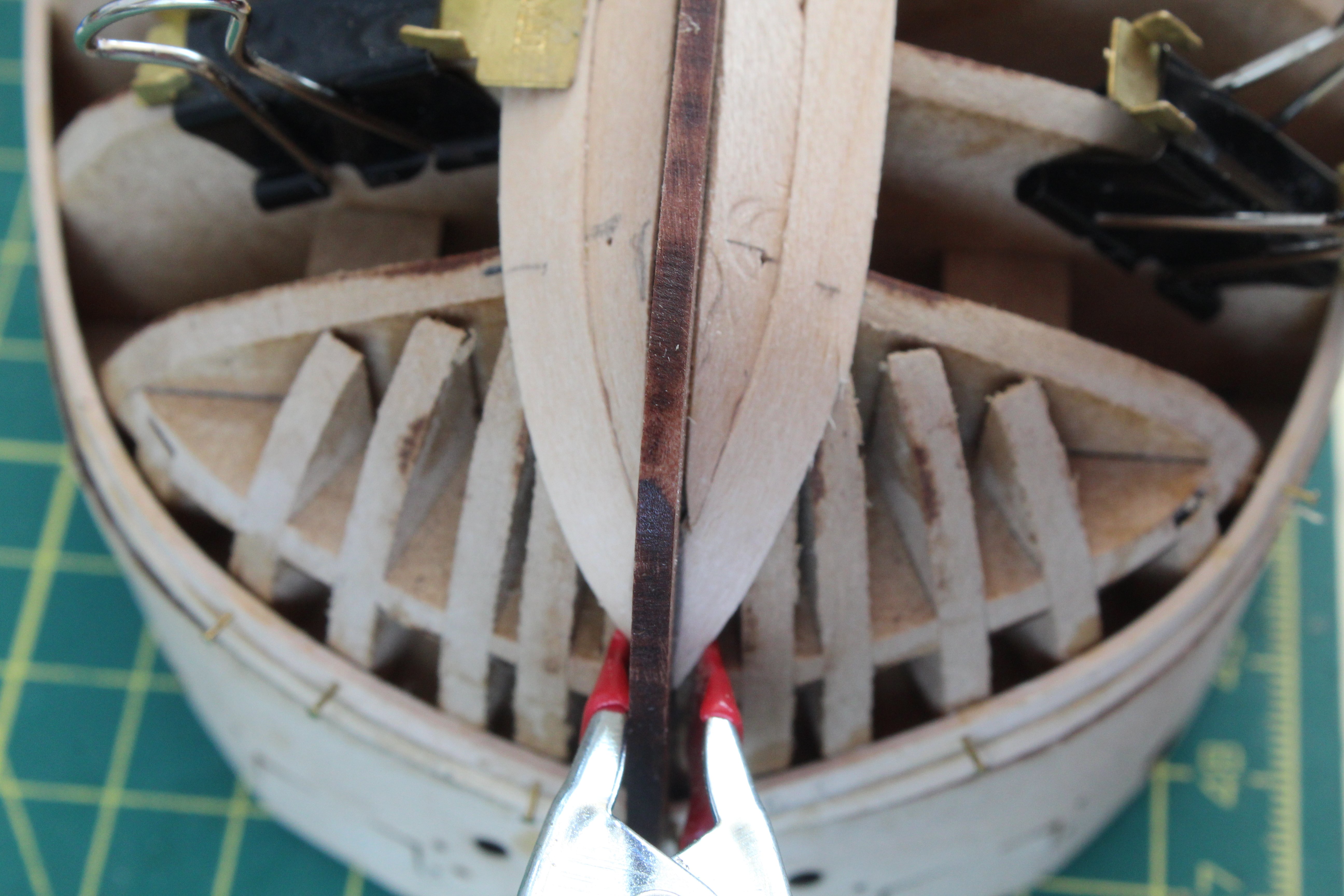
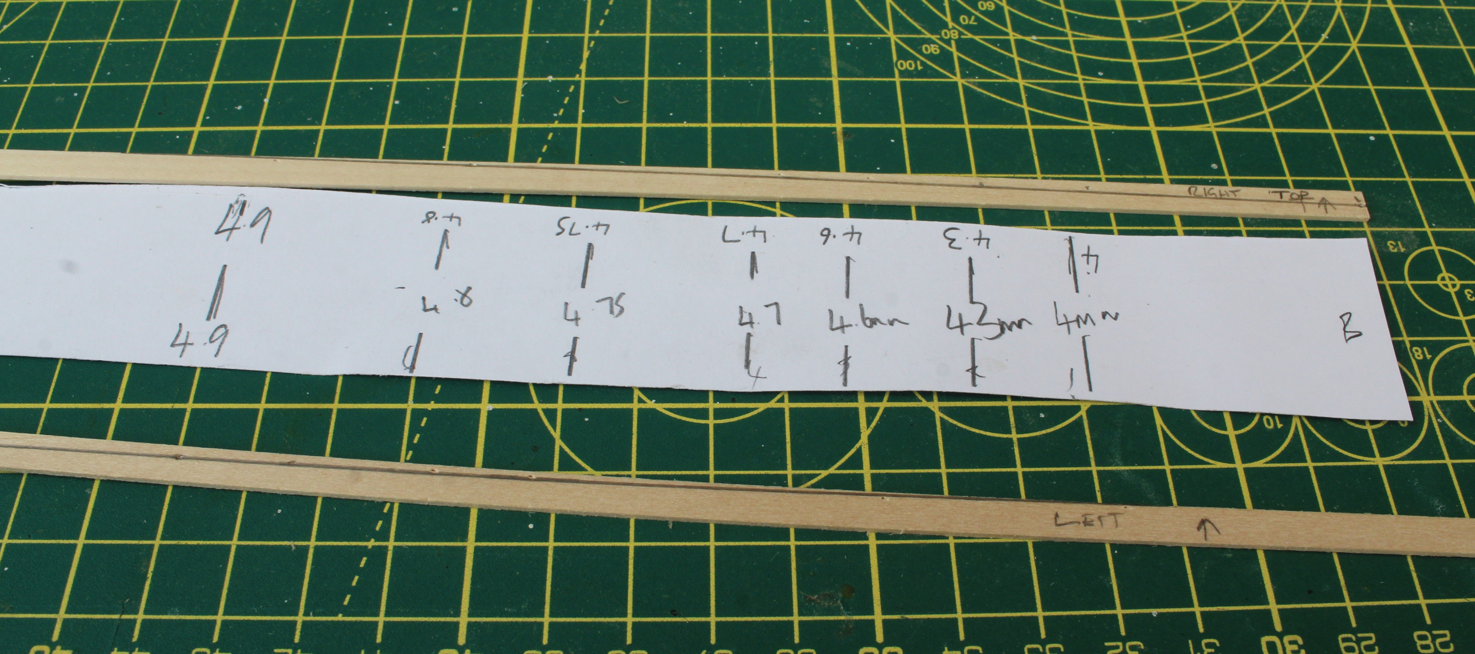
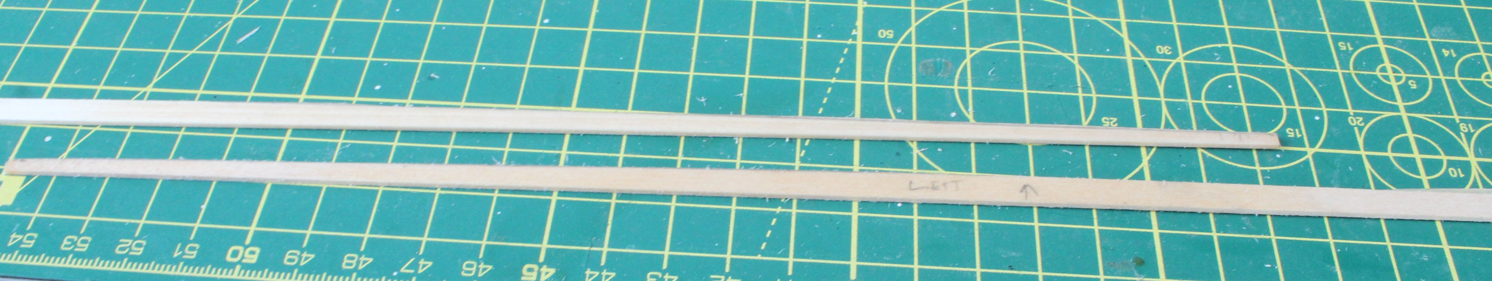
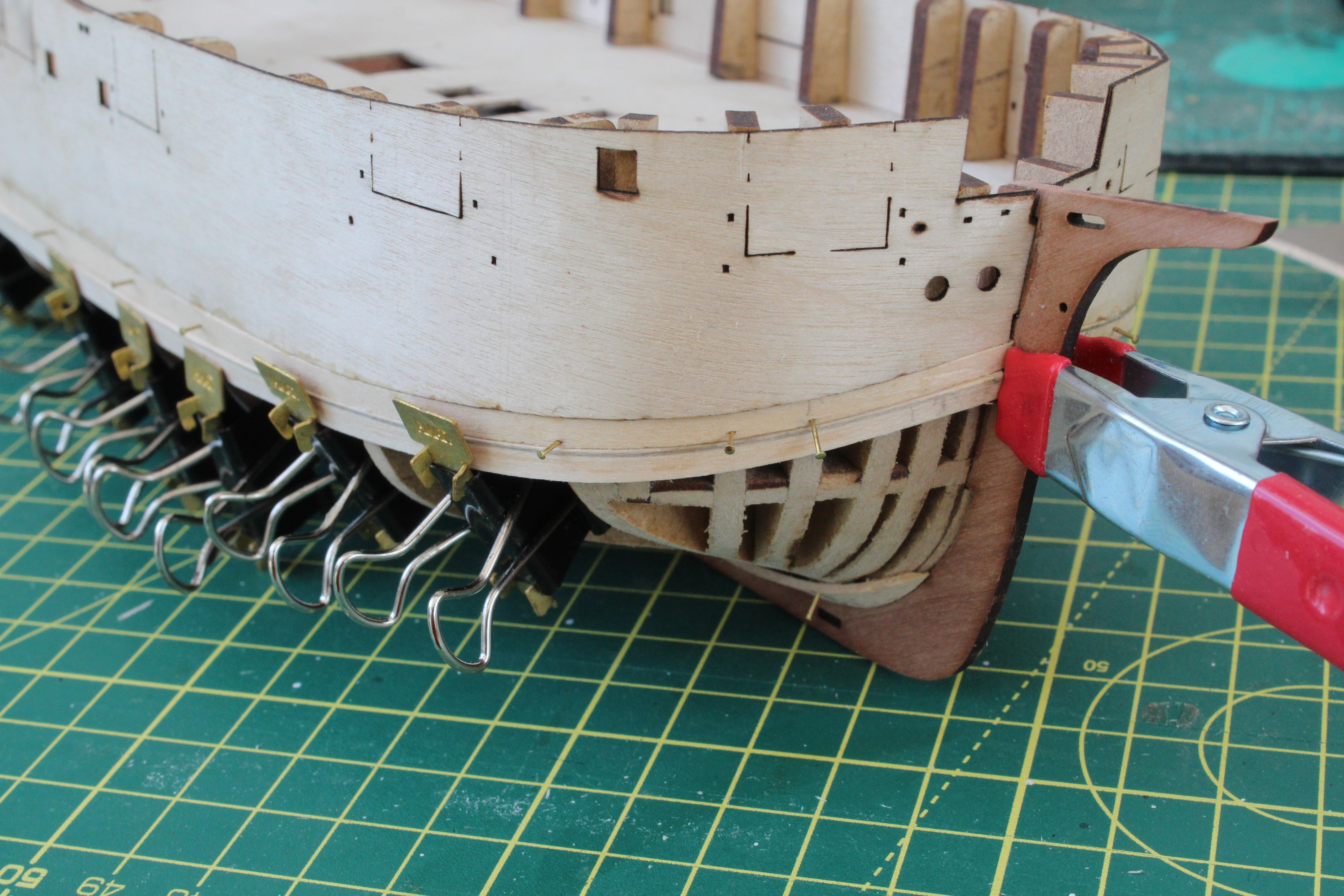
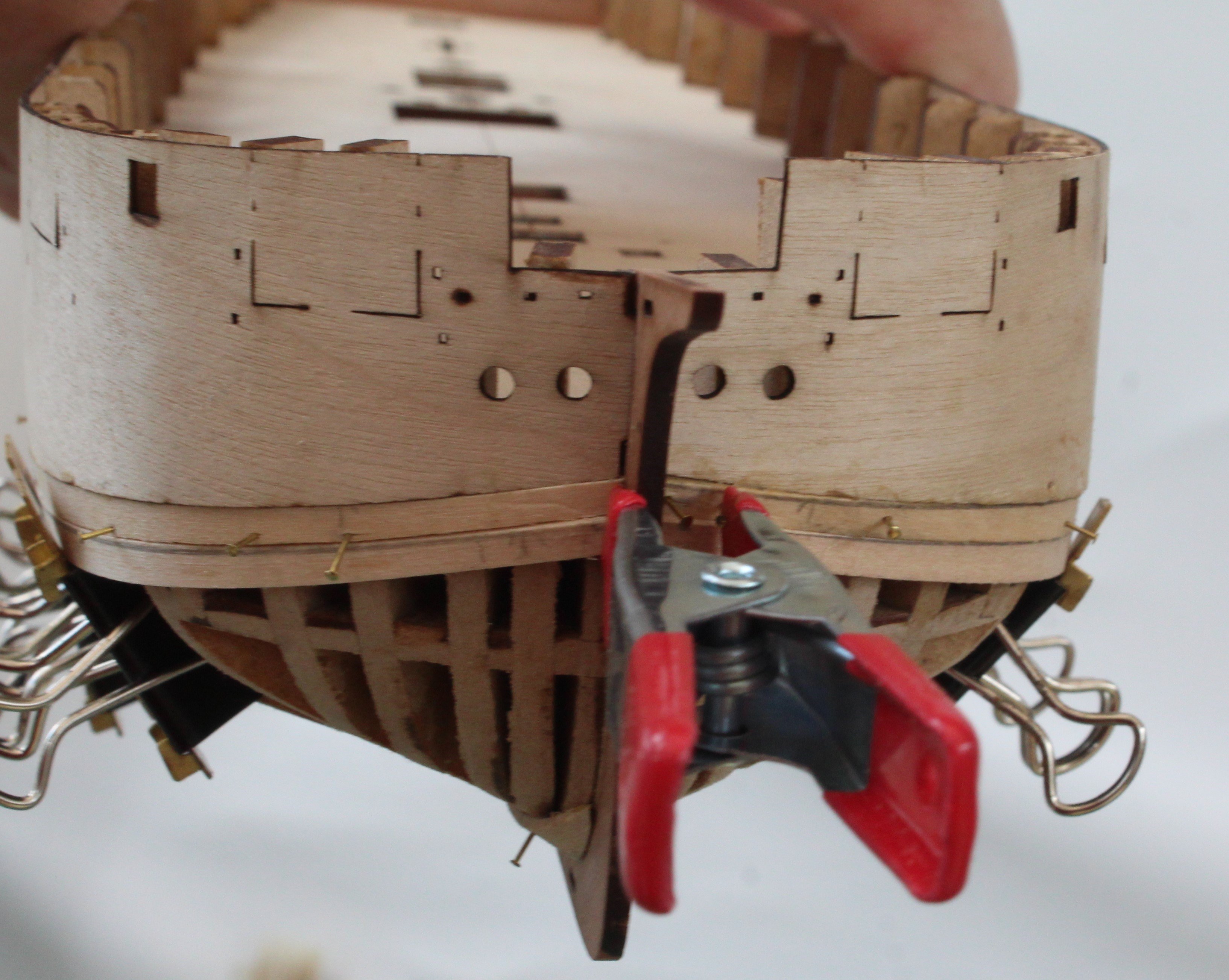
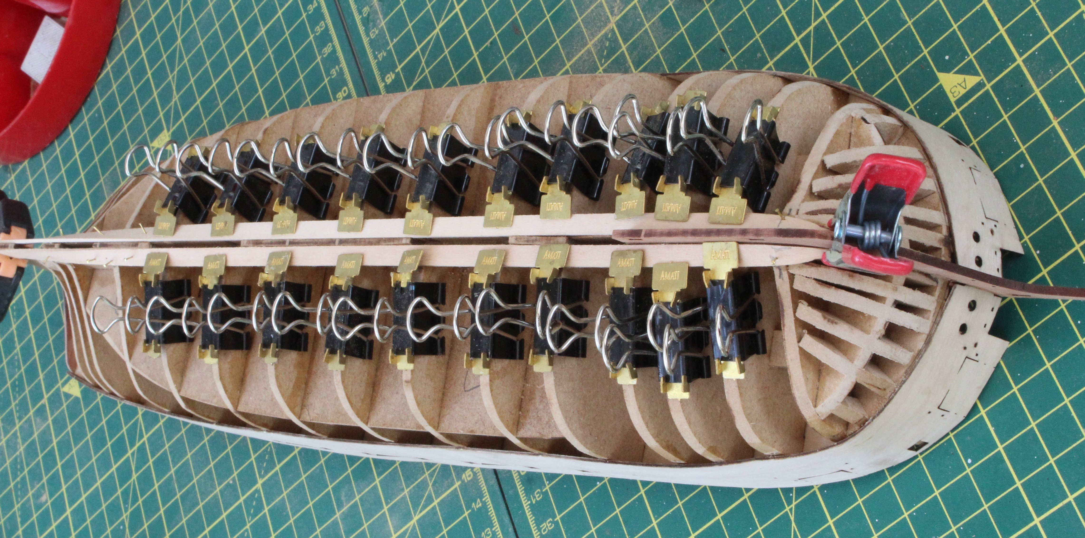
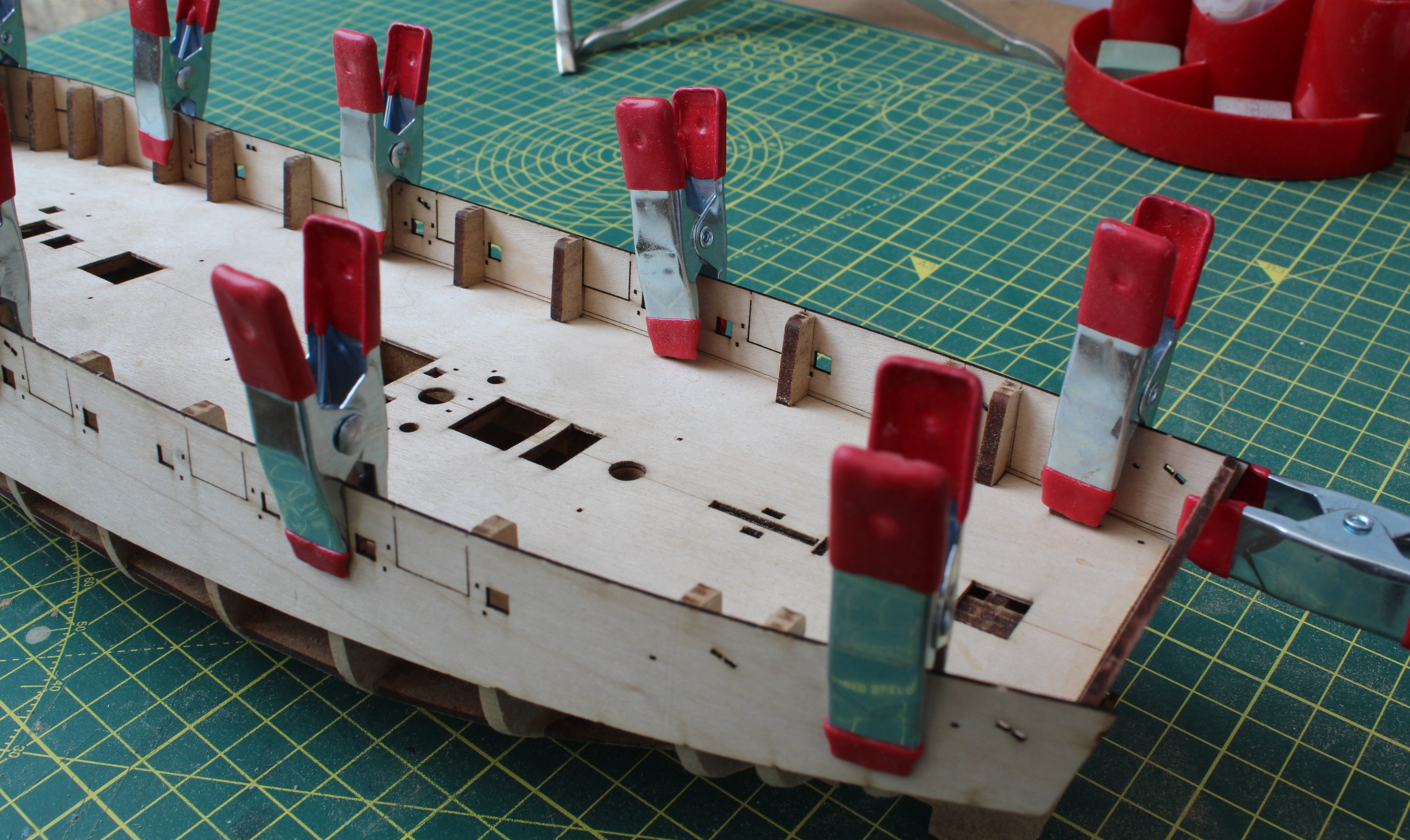
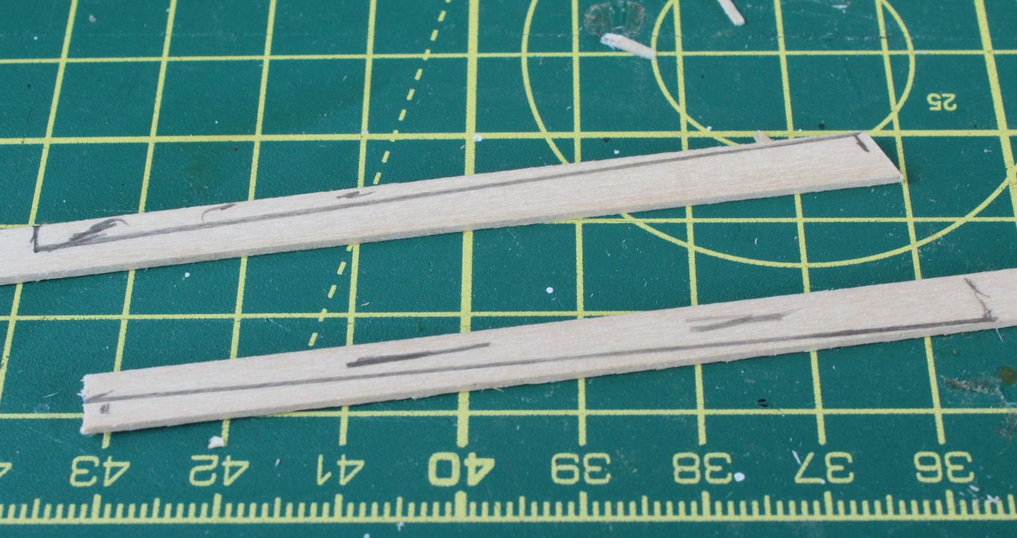
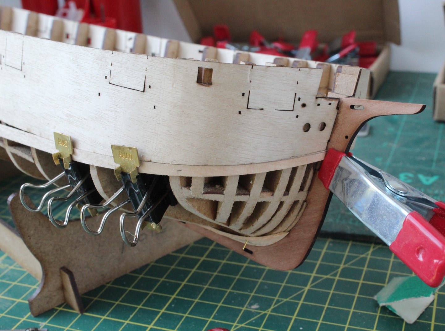
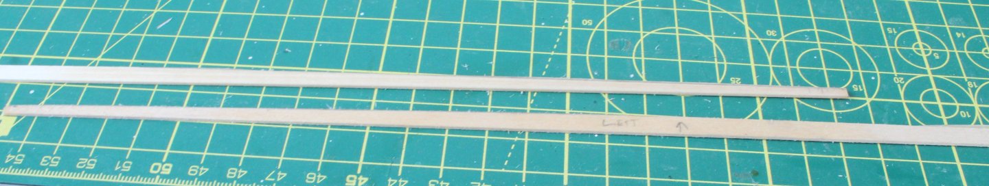
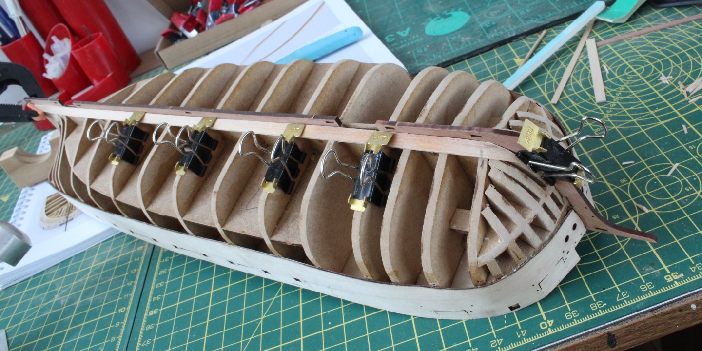
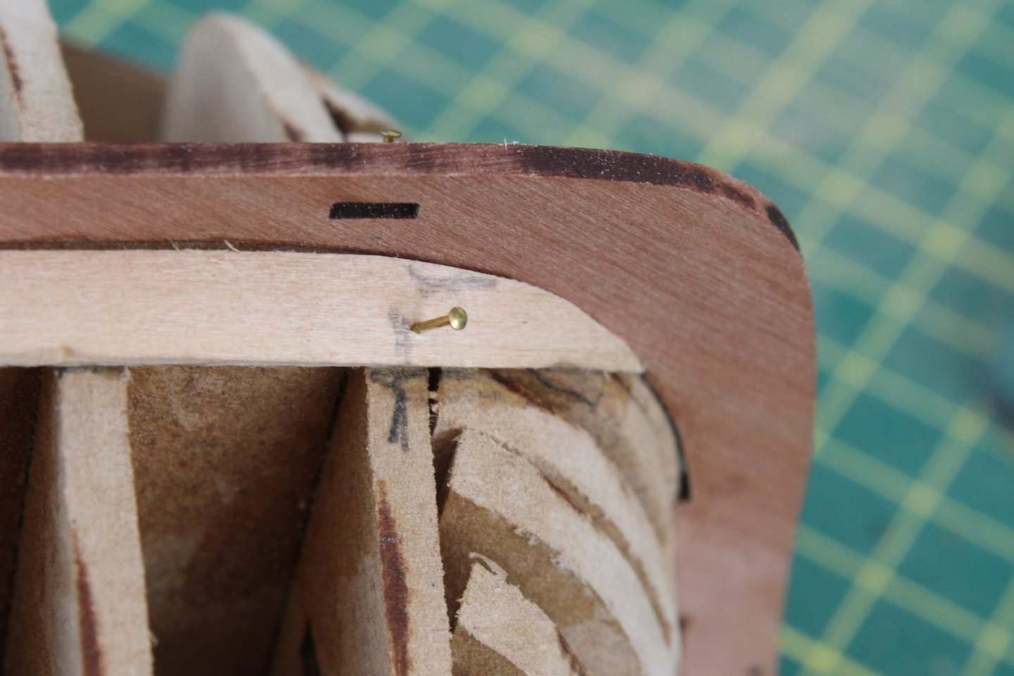
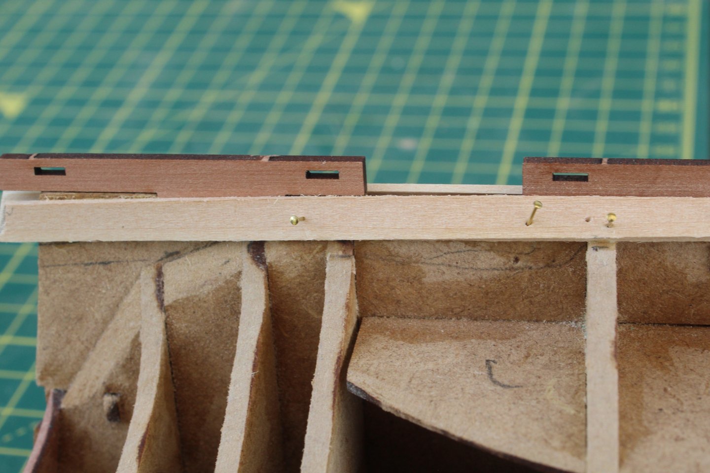
Build Log Index Date: 19/07/2024 to 20/07/2024 Time worked: 2 hours. Total time spent on build: 10 hours. Start of First Planking I took some measurements between bulwark and master plank which are listed in the table below. Location Length Plank Width Bow 30mm 2.5mm Bulkhead 1 48mm 4.0mm Bulkhead 2 52mm 4.3mm Bulkhead 3 55mm 4.5mm Bulkhead 4 57mm 4.7mm Bulkhead 5 57mm 4.7mm Bulkhead 6 58mm 4.8mm Bulkhead 7 58mm 4.8mm Bulkhead 8 58mm 4.8mm Bulkhead 9 58mm 4.8mm Bulkhead 10 58mm 4.8mm Bulkhead 11 56mm 4.7mm Bulkhead 12 55mm 4.5mm Bulkhead 13 52mm 4.3mm Bulkhead 14 54mm 4.5mm Bulkhead 15 55mm 4.5mm Stern 60mm 5.0mm Based on the above information then, at the midship area, 11 x 5mm planks required to fill the gap, together with a final 3mm plank to close the gap. The planks will require a taper toward the bow down to 2.5mm. Although the planks may require some tapering toward the stern I will let the planks run as natural as possible and will then trim / fit steelers as necessary. I started by making a test plank for the bow area. This was done to check the plank taper and hull fairing. I followed the advice in the build manual and soaked the plank in warm water for a few minutes before cutting the taper into the plank. The tapered test plank is a good fit around the bow. I am happy that the hull fairing is correct and that the taper is also correct. I then used a paper template to show the bulkhead positions and required width on the planks for the required taper. Using my digital vernier calipers I transferred the taper measurements to the planks. I then used a ruler and sharp pencil to draw the required cut line on both planks. I am tapering and fitting the planks in pairs (left and right) so both sides should look the same. This should also prevent any possible twisting/warping of the frames and keel as the glue cures. In the two photos below the top plank has been glued and pinned to the hull. The second plank has been shaped and they are test fitted / clamped to the hull and will now be left for a while to allow the planks to dry out and retain the shape around the bow before they are glued in place.


-
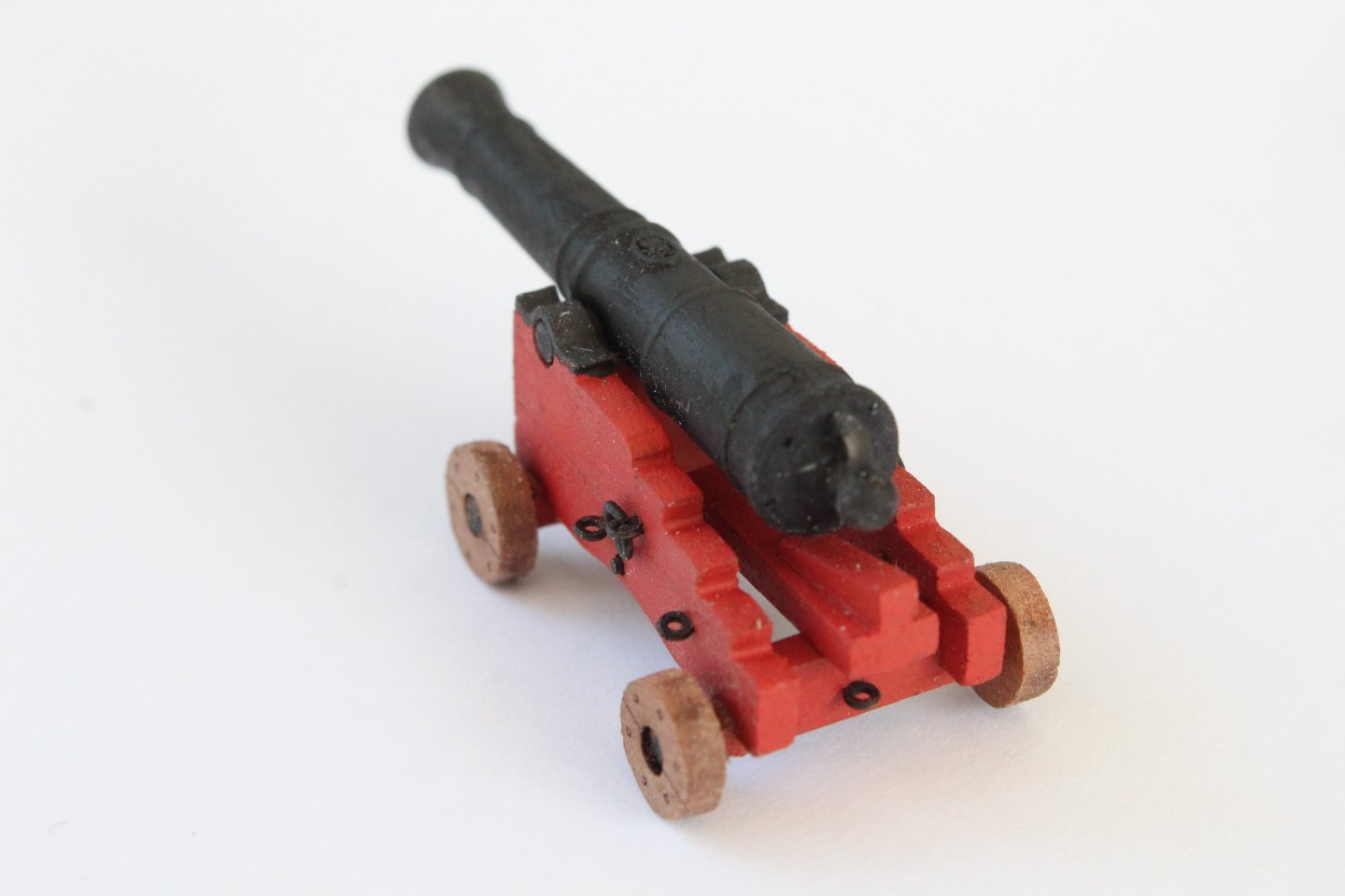
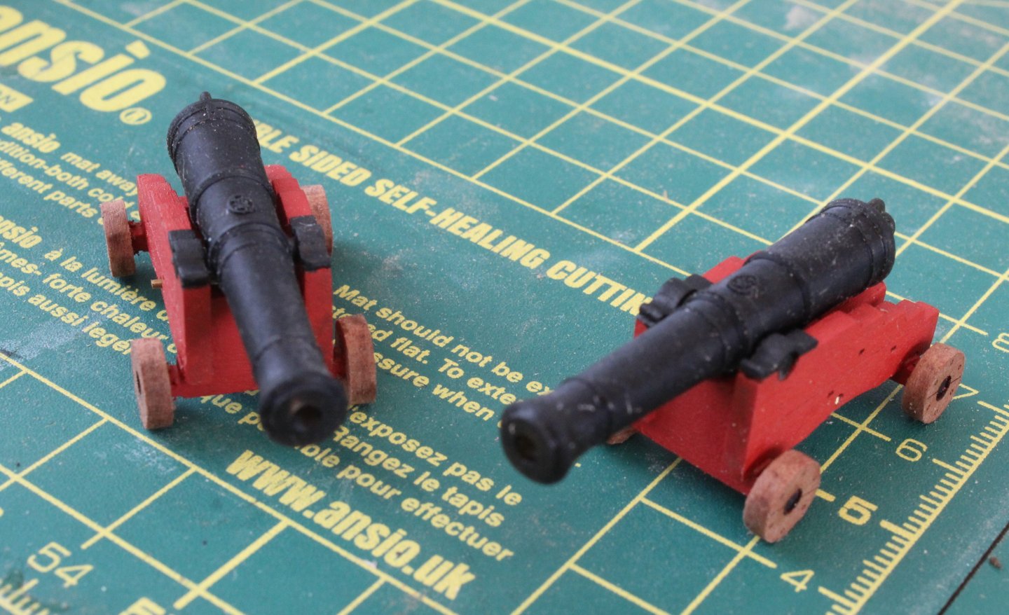
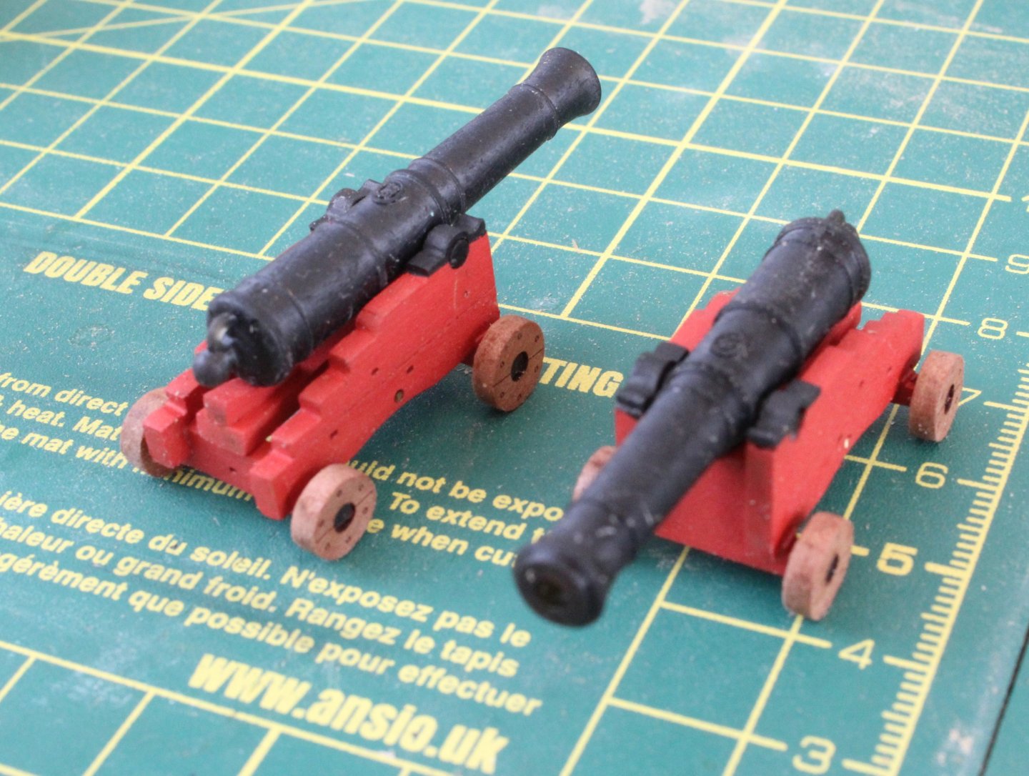
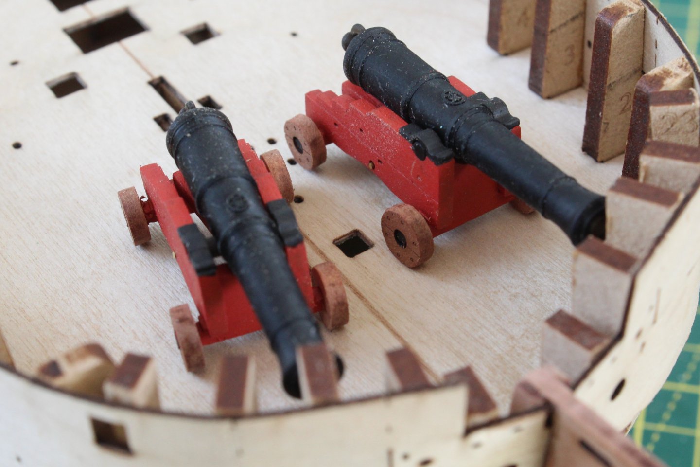
Build Log Index Date: 18/07/2024 Time worked today: 0.5 hour. Total time spent on build: 8 hours. 24-Pound Cannons There are 2 off 24-pound cannons to assemble. After I had removed the laser char from all the wooden parts I glued both left-hand carriage sides to their respective carriage front and rear axles. I then applied a coat of varnish to all the wooden parts and once the varnish had dried two coats of red and black paint were brushed on to all the carriage parts, excluding all the wheels. Once the paint had dried the right-hand carriage sides were glued in place, noting the 24-pound cannon also had to be fitted at this stage. It was then a case off adding the wheels. With a length of copper bar temporarily inserted the carriage stool bed and quoin were also added. The various eyebolts and copper bar will be added later on, when I am ready to chemically blacken them along with other PE parts. To complete this post the 24-pound cannons were placed on the sub-deck for a photo opportunity.


-
Thanks Theo. I like to keep busy but I sm taking this build very slow and steady
-
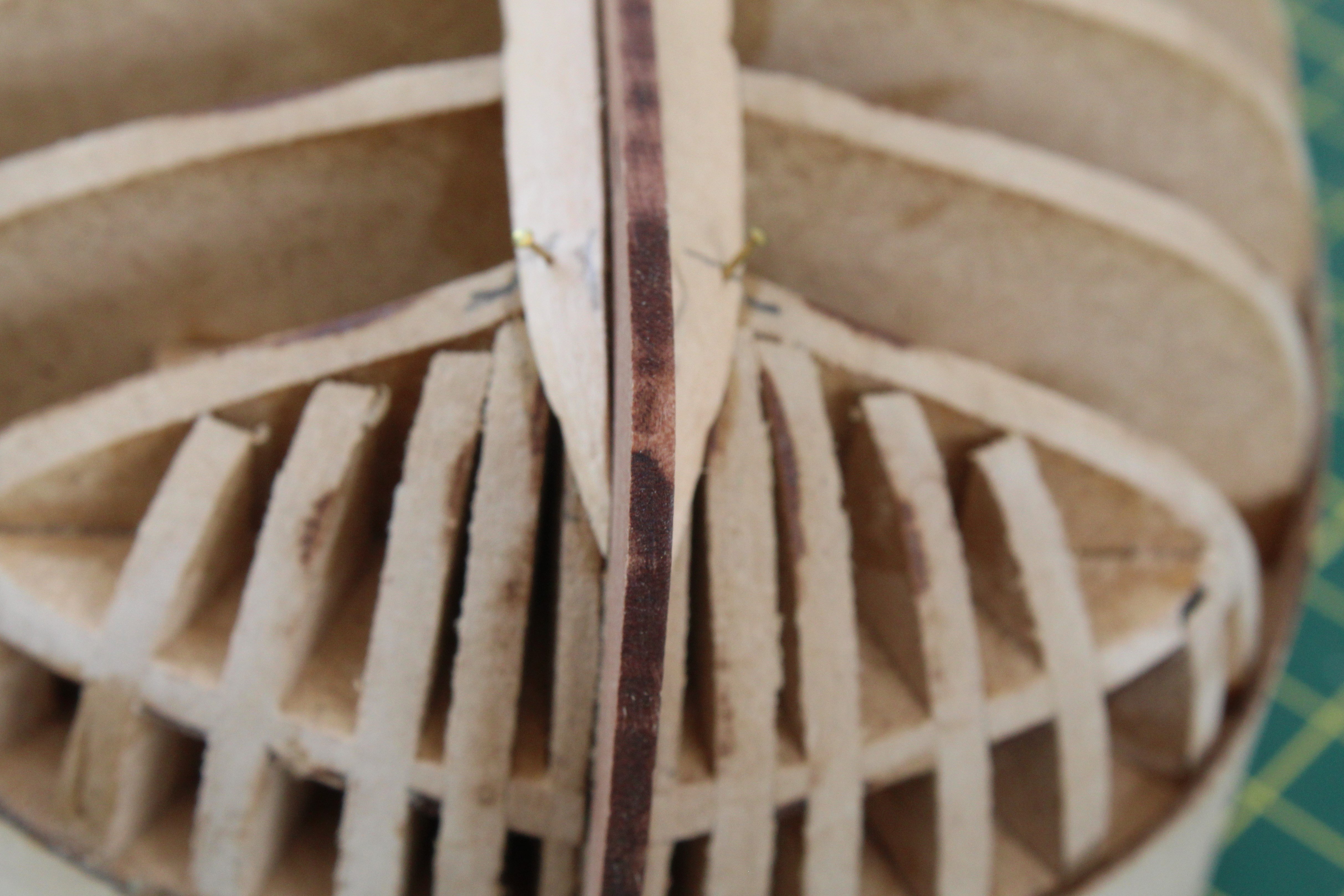
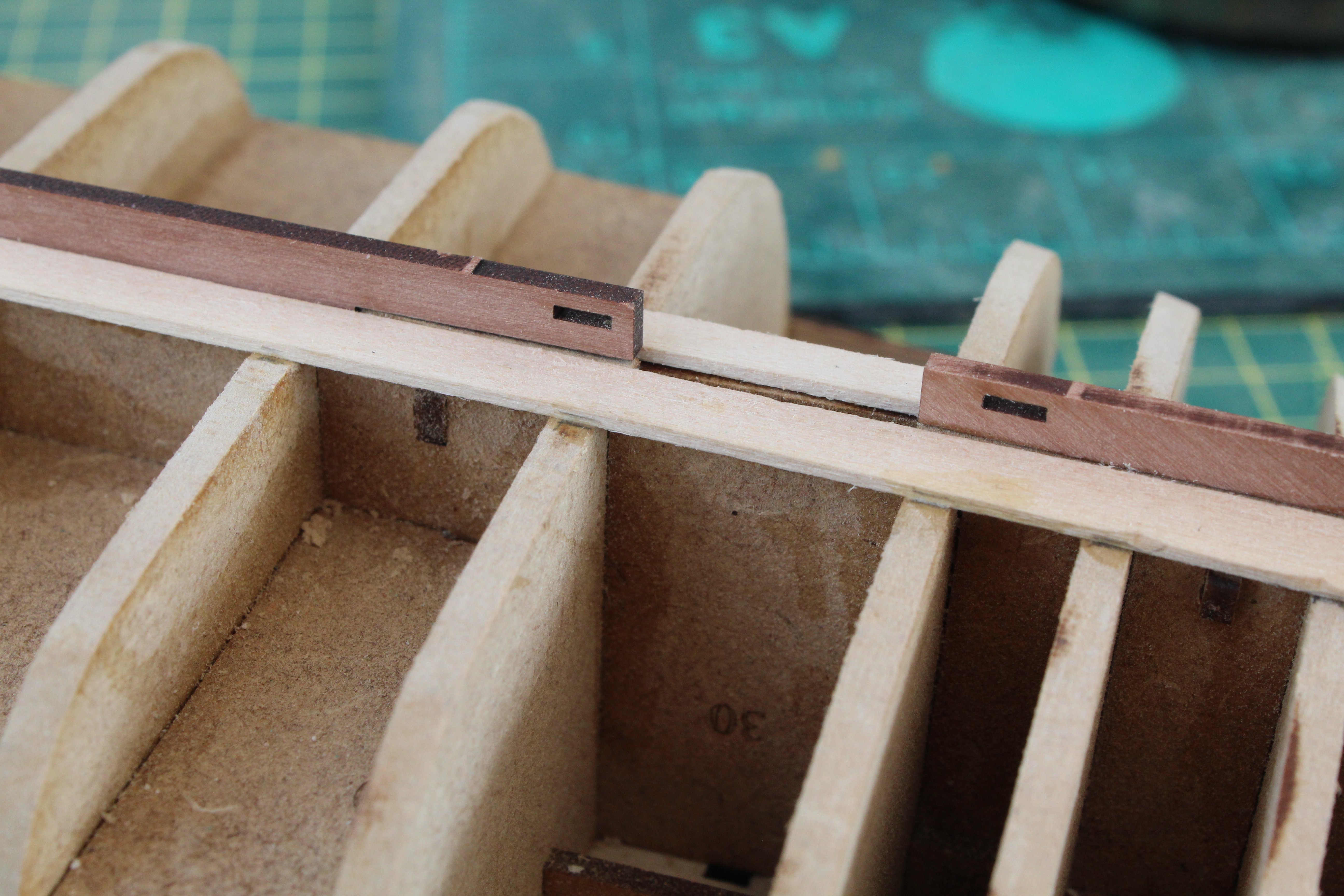
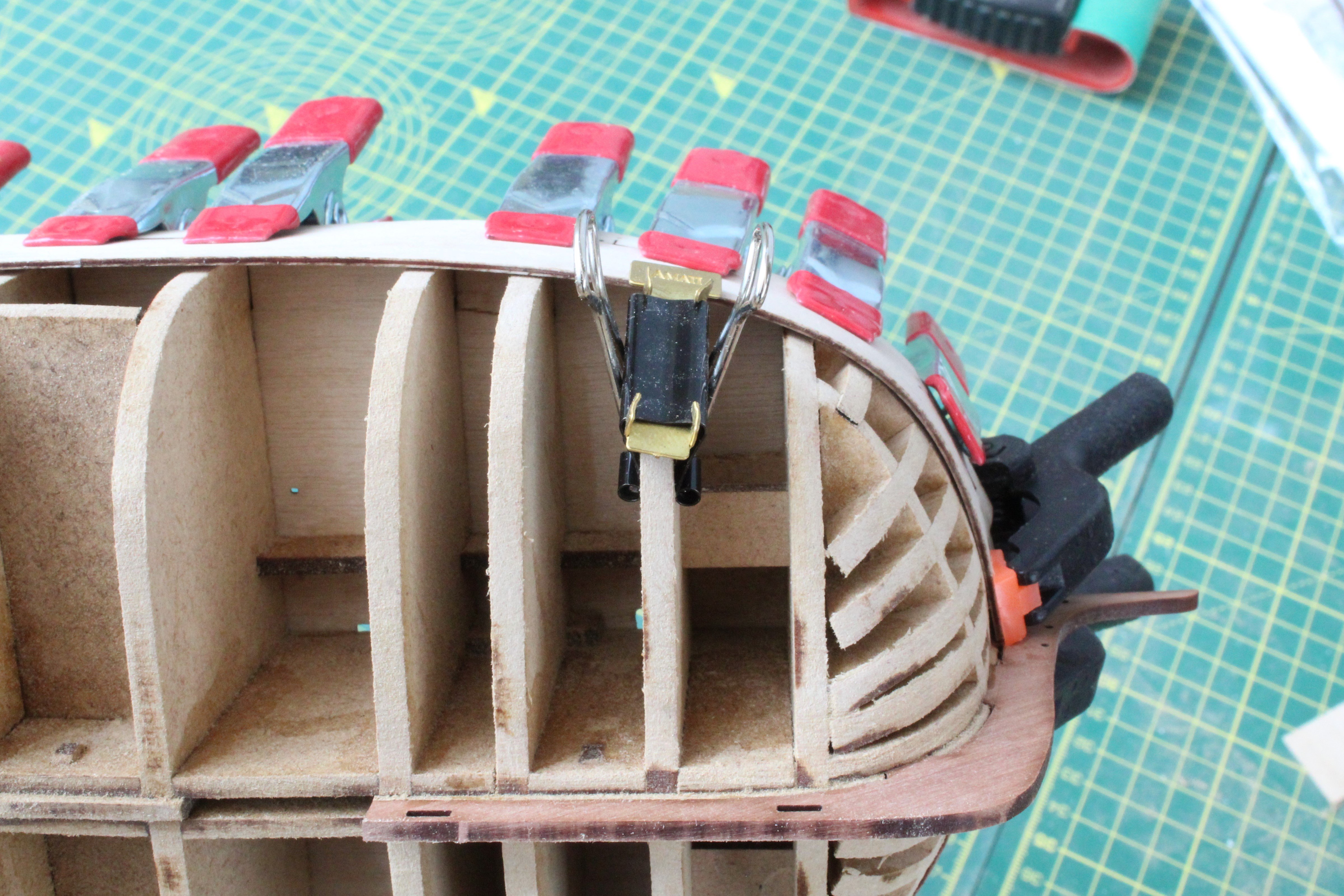
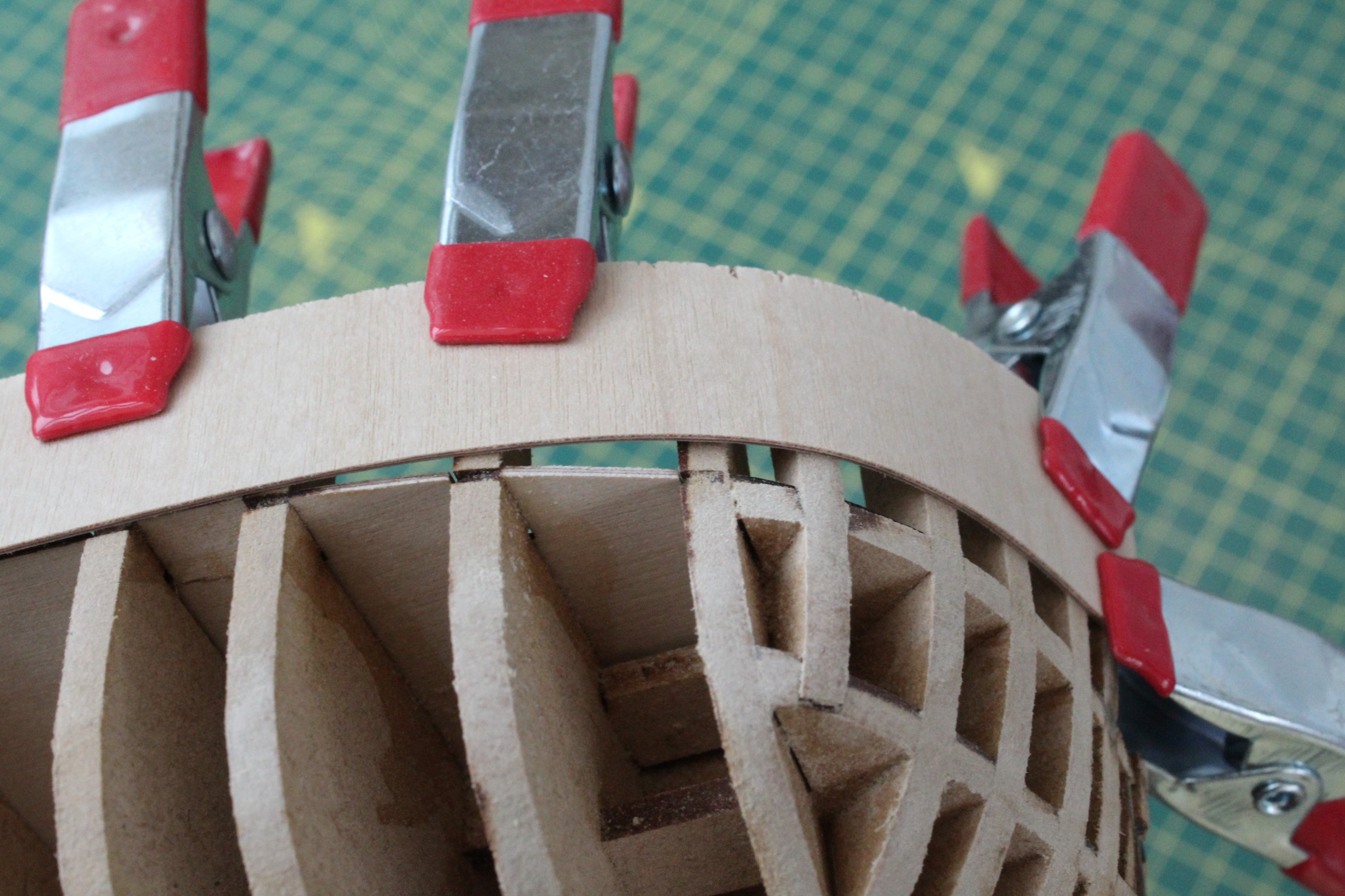
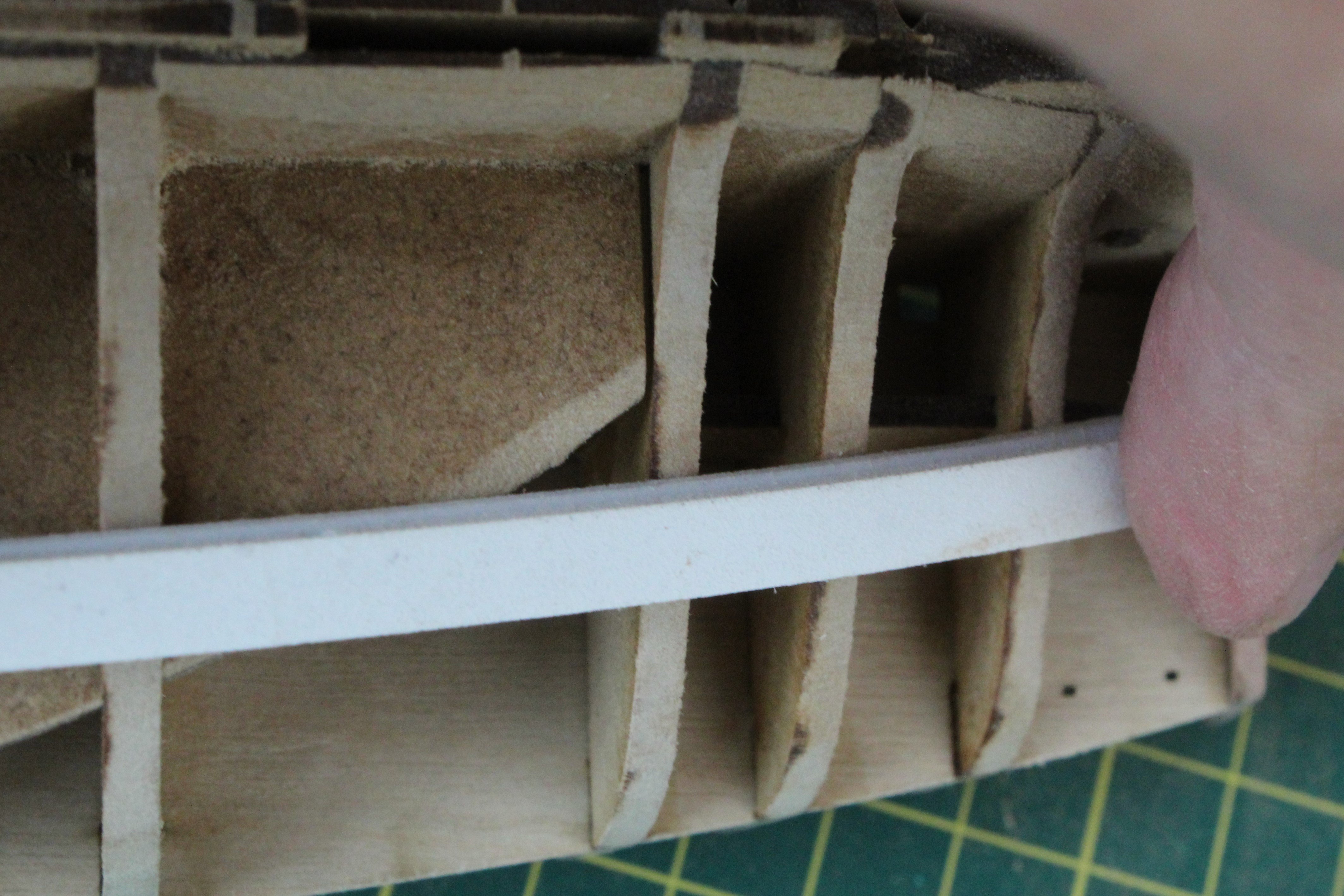
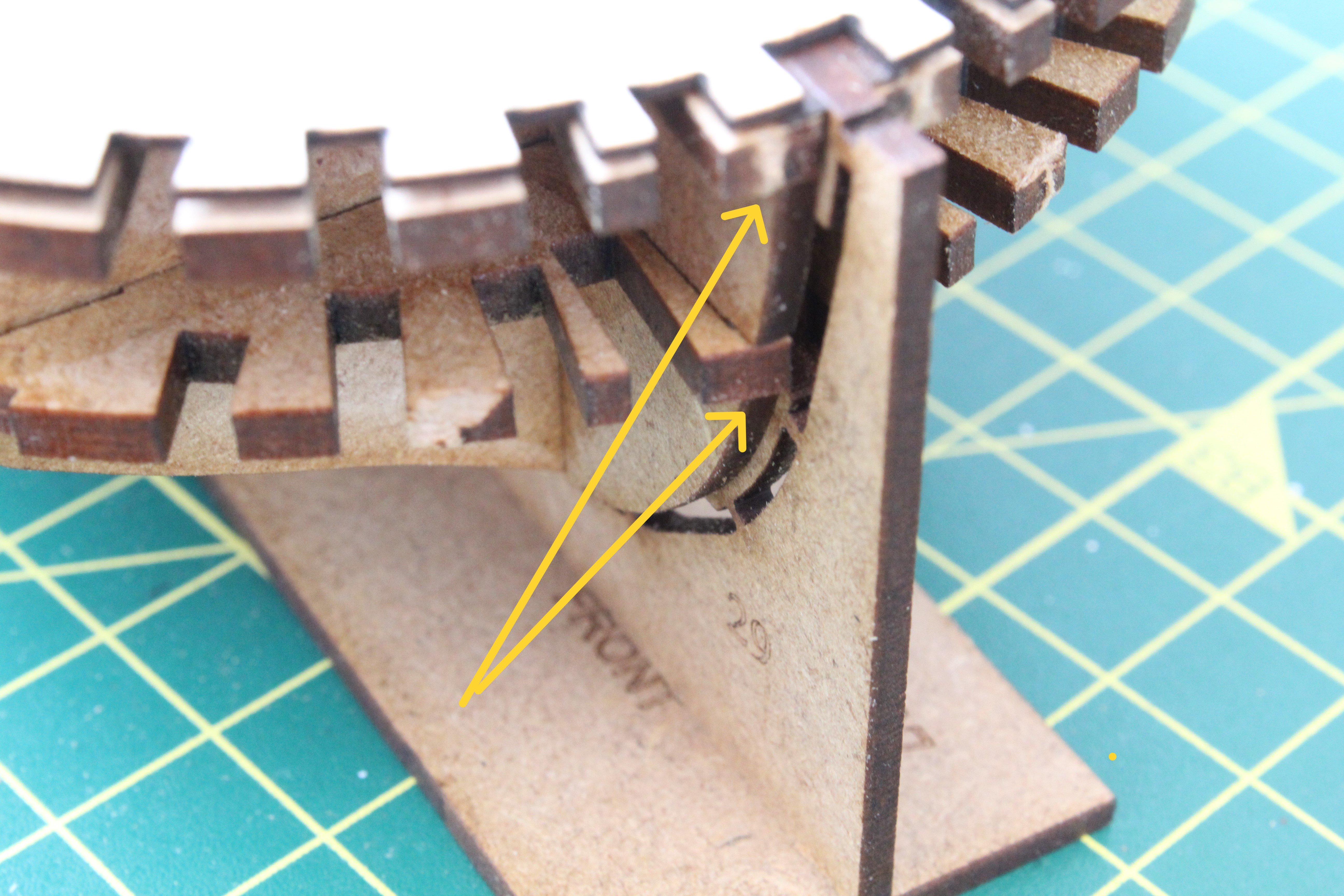
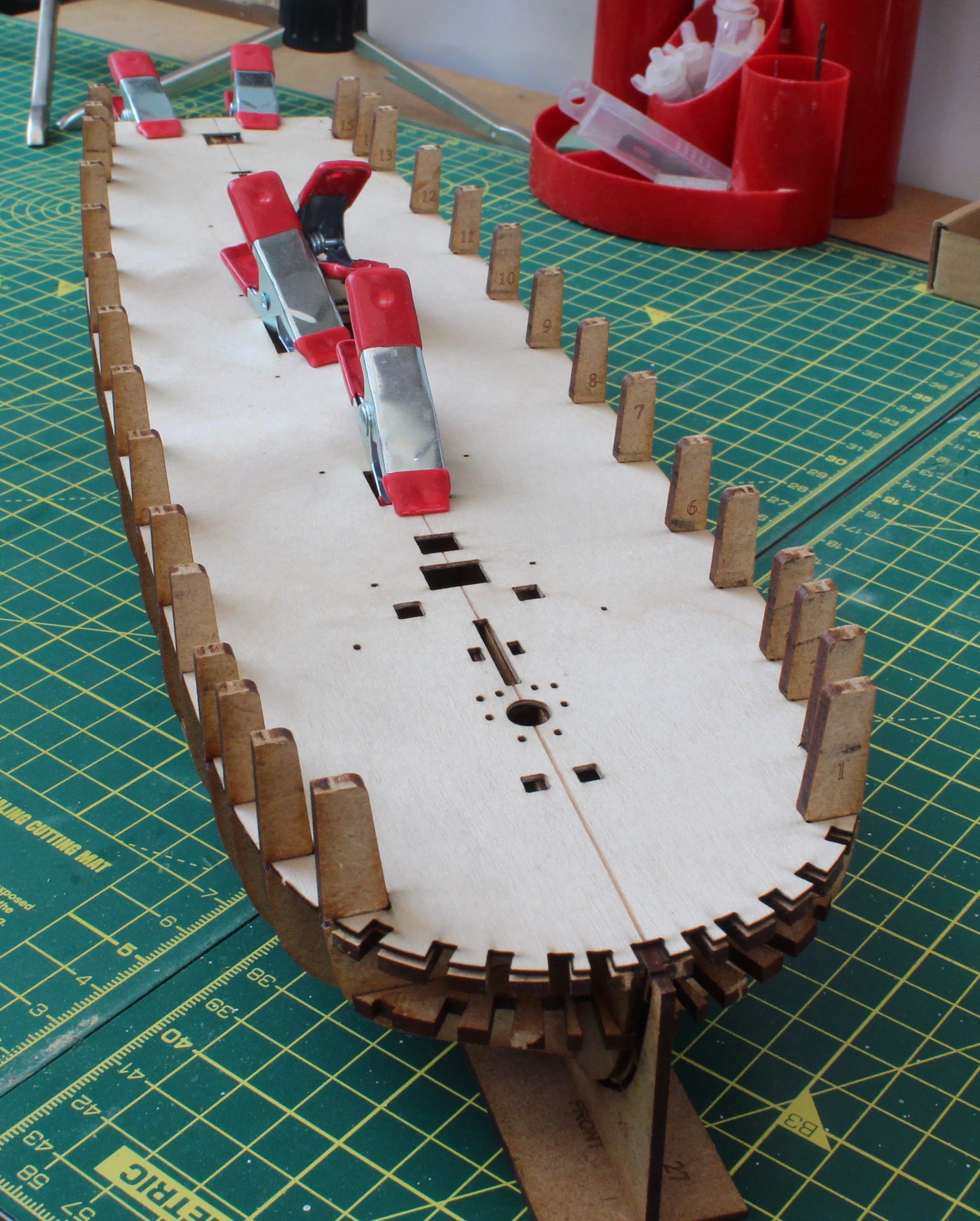
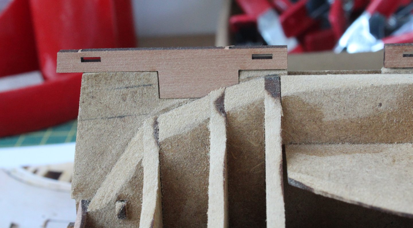
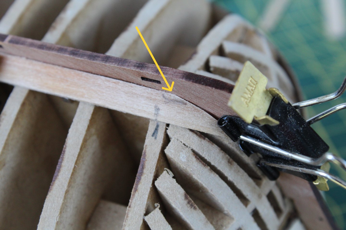
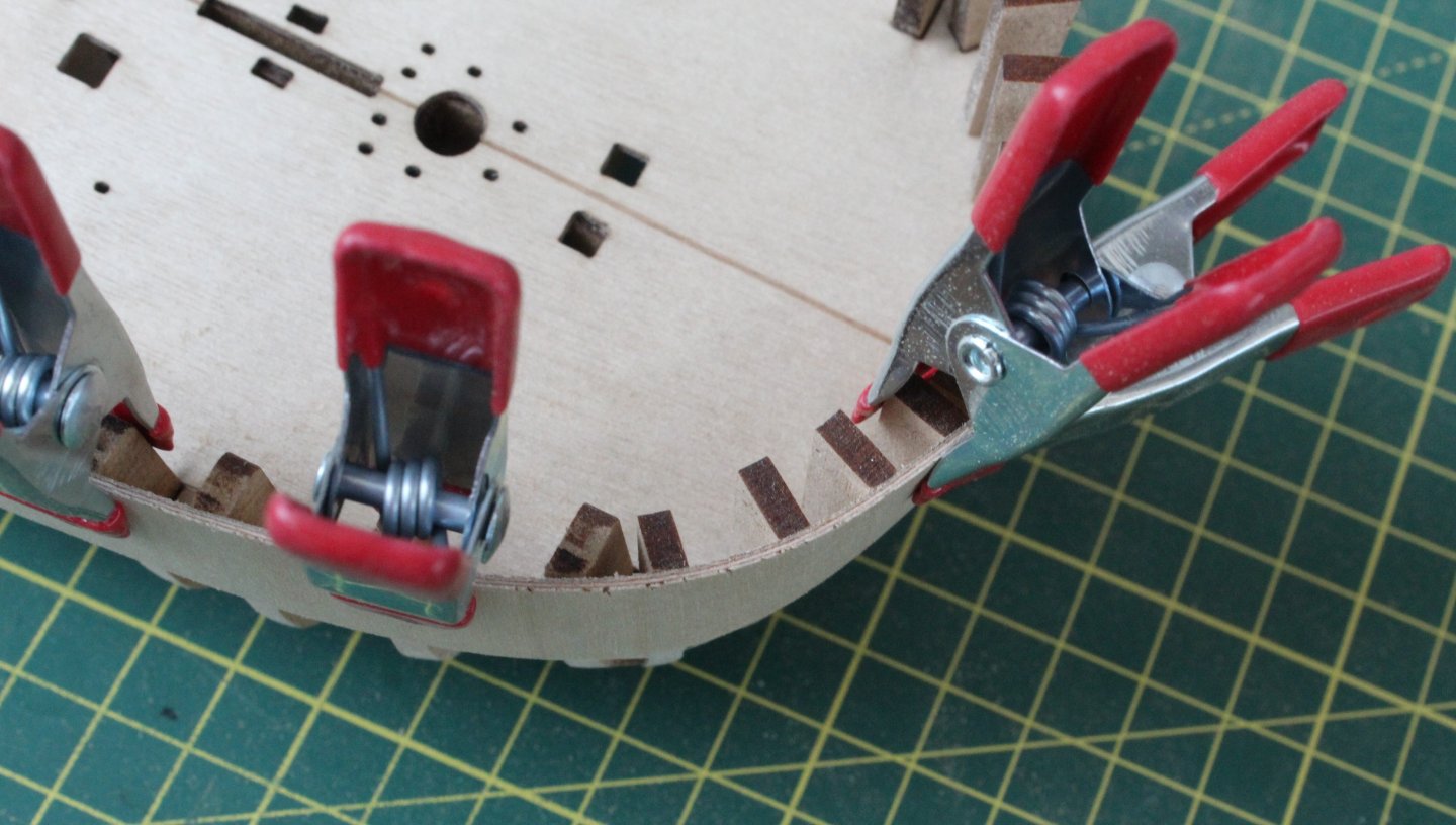
Build Log Index First Planking – Fitting The Master Plank Date: 18/07/2024 Time worked today: 1.5 hour. Total time spent on build: 7.5 hours. Master Plank I am following the recommendation in the build manual to fit the lowest (master) plank first. I started by shaping the bow end of each plank. The aim, when fitted, is that these planks will follow the curve of the bow. In the photo below I have prepared the initial shaping of the master planks. They will now be soaked in some hot water before using my heated plank bended. I did mark the start point for the bend on these planks, as indicated by the yellow arrow. While the master planks were soaking in the hot water for a few minutes I did a test fit of the main keel and main keel (aft) parts. After the initial bending of the bow end of the master plank they was test fitted. As can be seen in the following photo, they were both a reasonable fit, however I will need to sand a small area, as indicated by the arrow. Using some Amati clips the master plank was test fitted along the entire length of the hull with the main keel and main keel (aft) dry fitted. This is to make sure there were no areas on the hull which would require more fairing. Using a spare piece of planking material the outer main keel pattern was simulated. As can be seen the master plank fits perfectly with the outer pattern. This means that the first planking will require some sanding to reduce the thickness so that the second planking will sit flush with the outer keel pattern. After sanding the master plank bow shape a little bit more I was much happier with the fit. Both master planks were then glued in place. For the most part I used Amati clamps to hold the planks in place but used a few pins where necessary. After the glue had had time to cure the Amati clamps were removed. I was happy with the bow area. The main keel and main keel (aft) were once again dry fitted and I was happy with how the master planks look. To complete this post I have added a photo showing how the bulwarks are nicely aligned with the sub deck.


-
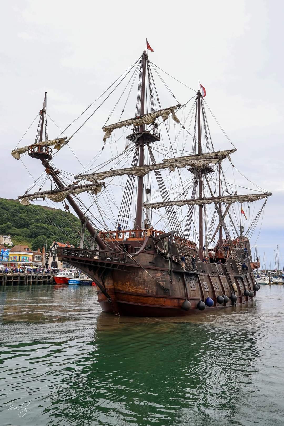
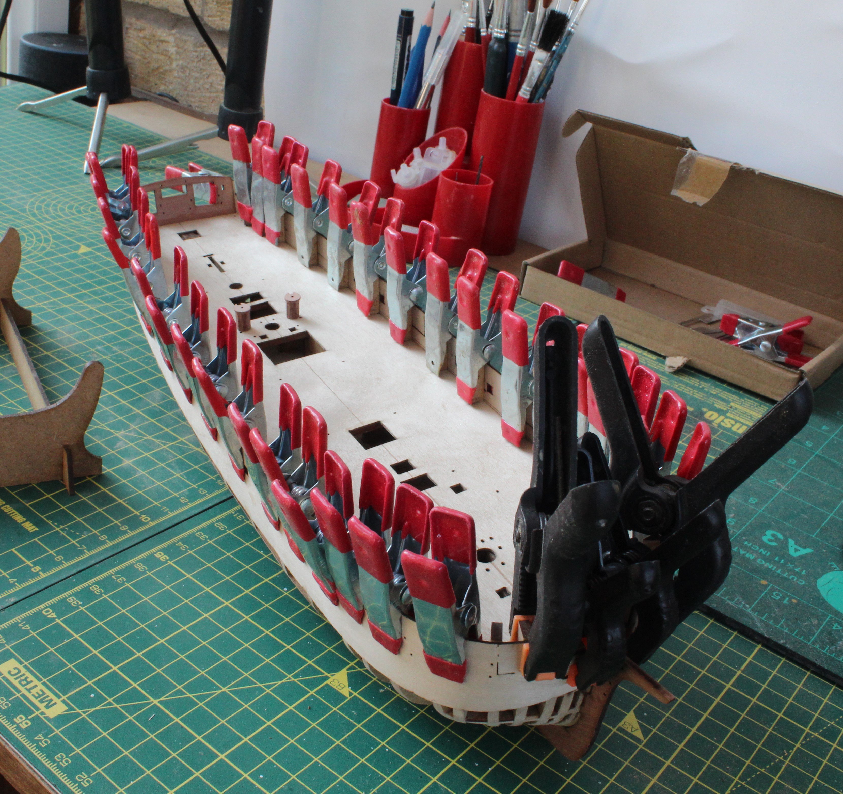
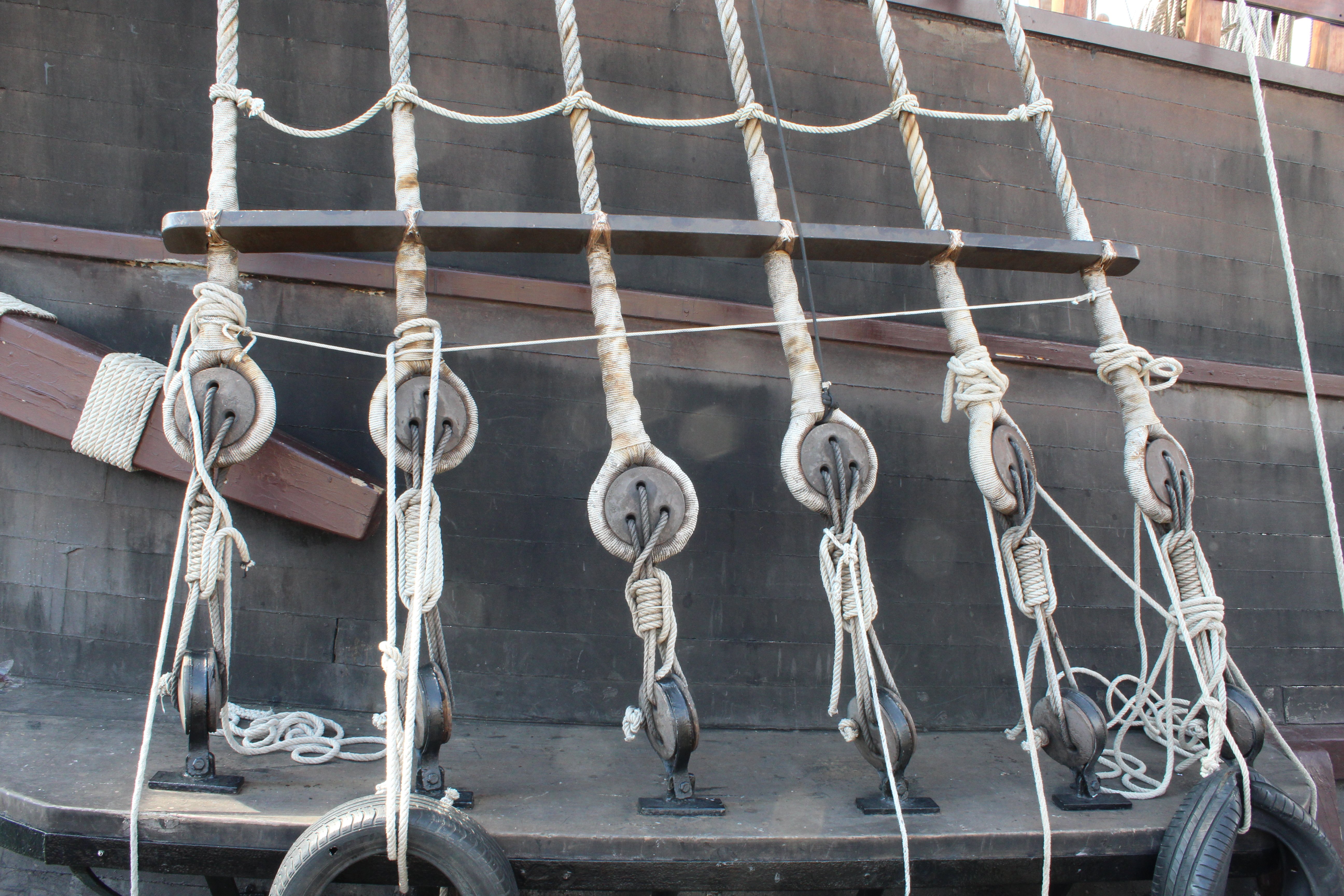
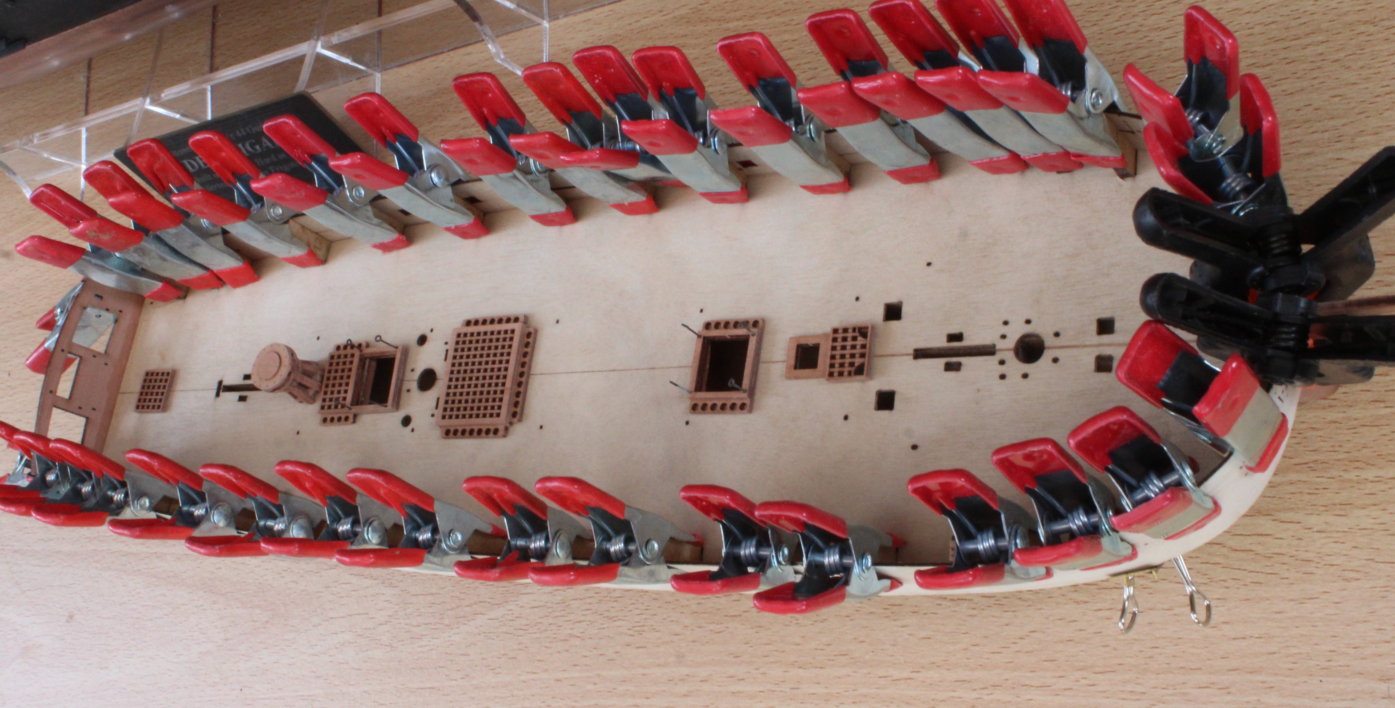
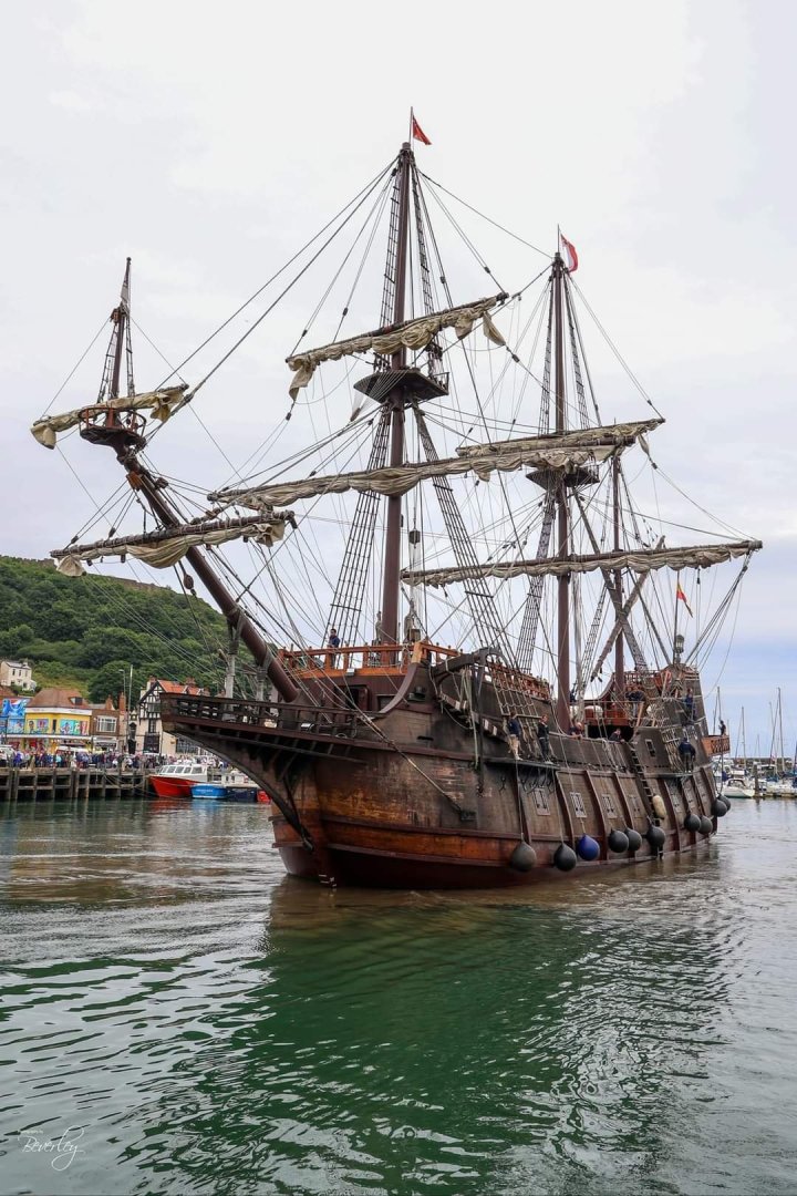
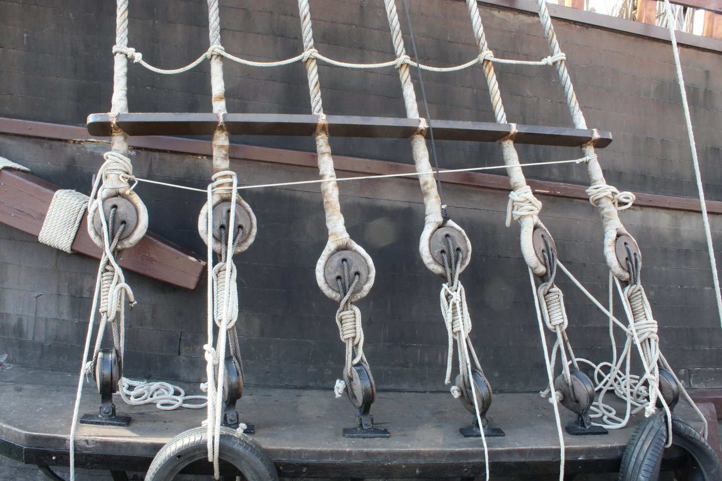
Build Log Index Bulwarks and Galeon Andalucia Date: 17/07/2024 Time worked today: 30 minutes Total time spent on build: 6 hours 30 minutes. Bulwarks After leaving the bulwark patterns pinned to the hull for 24 hours to fully dry out they were removed and had retained the required bend so I felt confident they could be glued in place. With the bulwarks temporarily in place I marked the position of the bottom edge on each of the bulkhead and bow frames. With the bulwarks removed watered down wood glue was then brushed on to the bulkhead and bow frames above the marked lines. The bulwarks were then carefully positioned and aligned, starting with the bow end. Clamps were used to hold these patterns in place on each bulkheads. No pins were required on the lower edge. As I waited for the glue to cure, I did start to assembly the two hand pumps which were test fitted to the hull. After 24 hours I removed the clamps. The bulwarks patterns look even at the bow. There seems to be good contact with the bulkheads and bow frame on the lower edges. I am happy with how they look. Galeón Andalucía The Galeón Andalucía sailed into Scarborough yesterday afternoon. It is a replica of the ship used by the Spanish Crown for maritime expeditions of discovery during the 16th through the 18th centuries and she is the only one in the world that still sails. I went for a look around the Galeón Andalucía this morning. It was interesting, and I did take quite a few photos. There were one or two things which caught my eye, such as the how the lanyards were rigged and the alignment of the channel deadeyes. I also noted that wooden spaces were used on the shrouds. You can view a slide show of all my photos at: https://youtu.be/KgCx2wdWpfQ


-
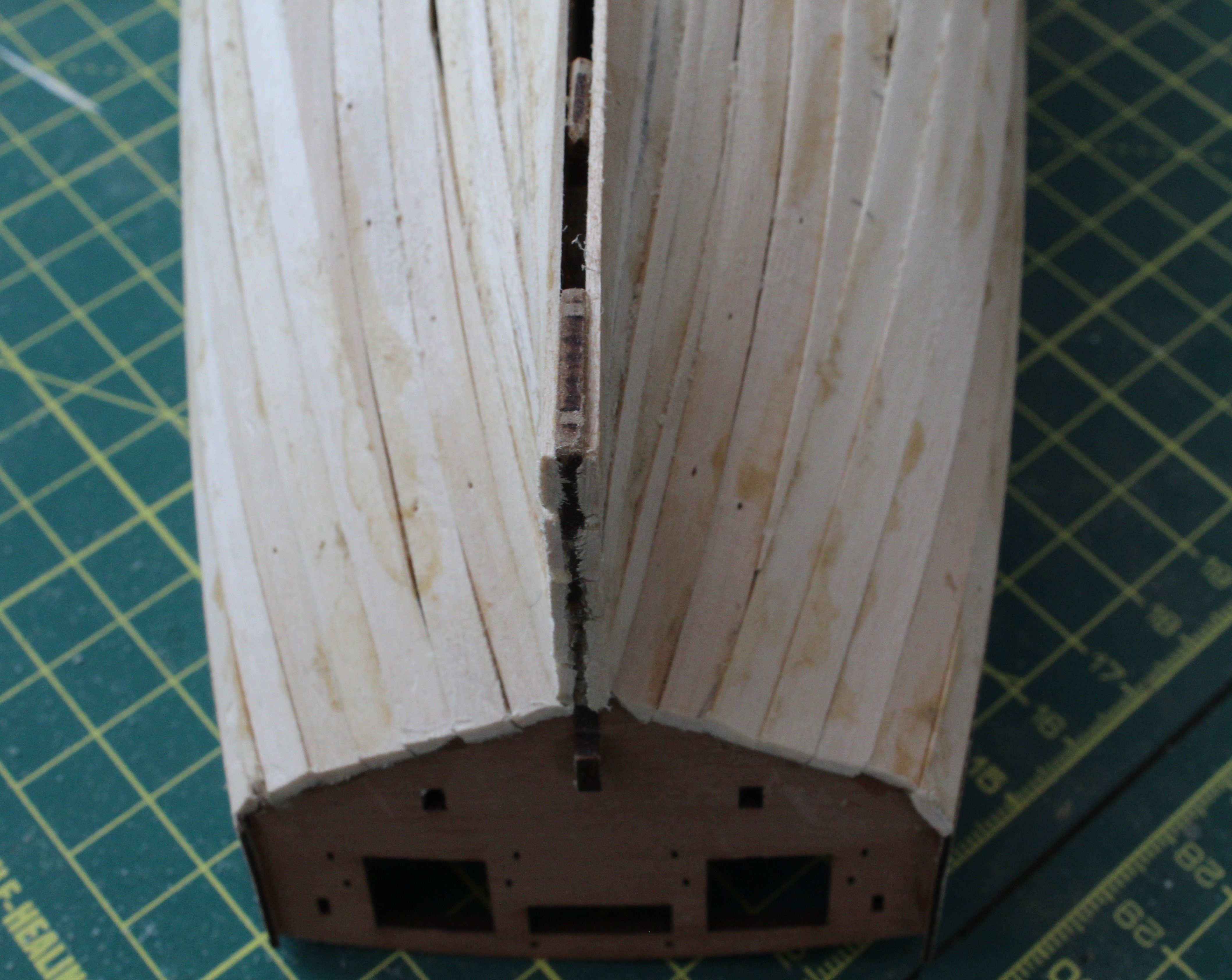
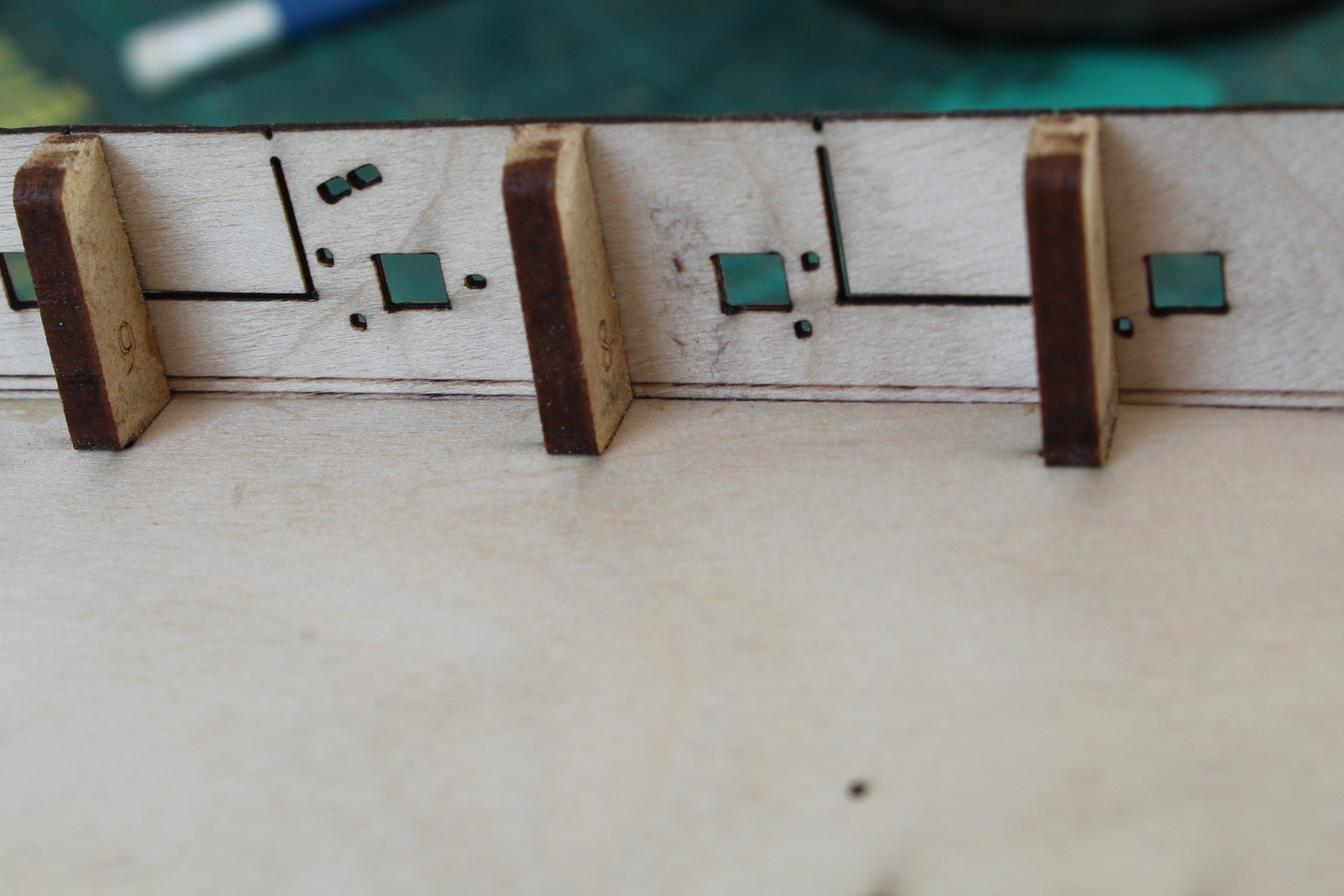
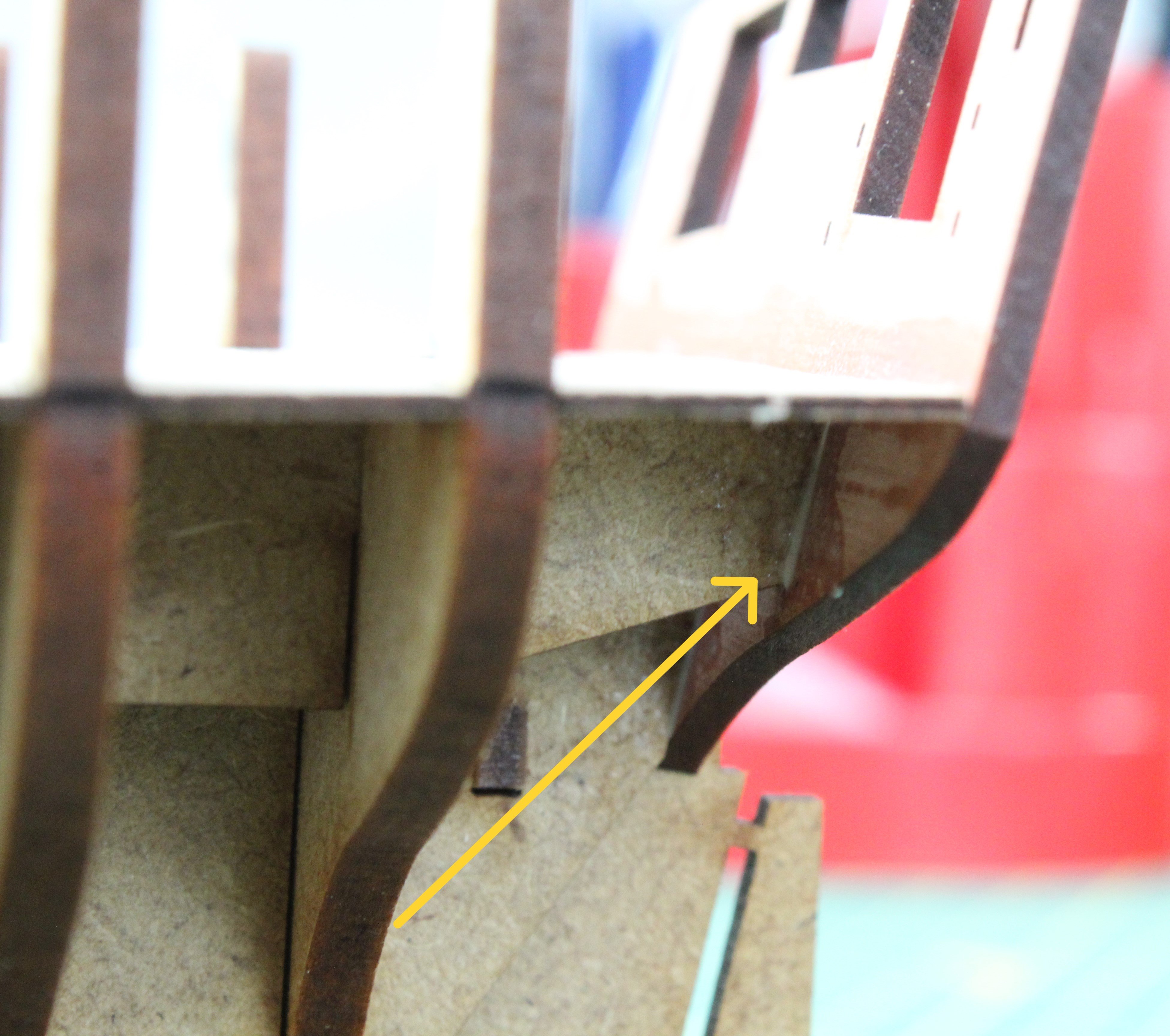
Build Log Index Preparation for first planking Date: 16/07/2024 Time worked today: 0 hour. Total time spent on build: 6 hours. Planking Considerations As we have had family staying with us for the last couple of days my shipyard time has been very limited and I have not been able to spend any time in the shipyard today. I have been giving some thought to the first planking, which I plan to start in the next day or two, and what I should do with regards the area where planking meets the the stern post / main keel (aft). The keel width is 2mm. The planking width is 1mm (per side) for the 1st on 0.8mm (per side) for the second. This means the total thickness, where the keel abuts with the stern post is 5.6mm, i.e. 2mm + (2 x 1mm) + ( 2 x 0.8mm). The overall thickness of the stern post and main keel (rear) is only 4mm. There are three possible options to consider: a) Mark out a dead area on the keel and to taper down to approx. 0.6mm, noting there will be bit of sanding required after the 2nd planking has been completed. b) Reduce the width on the keel down to approx. 2.6mm after the first planking, noting there will be bit of sanding required after the 2nd planking has been completed. c) Terminate the 1st planking short of stern post area. This would mean the thickness would be 3.8mm once the 2nd planking has been added so some filler would probably be required. I will do a little bit of experimentation with some test planks before deciding on the best way forward. When looking at the photos in the build manual it would seem the prototype used option b, apart from the area where there seems to be a gap between the lowest 1st plank and where the main keel (rear) fits but there is no filler shown in that area after the 2nd planking had been added.
-
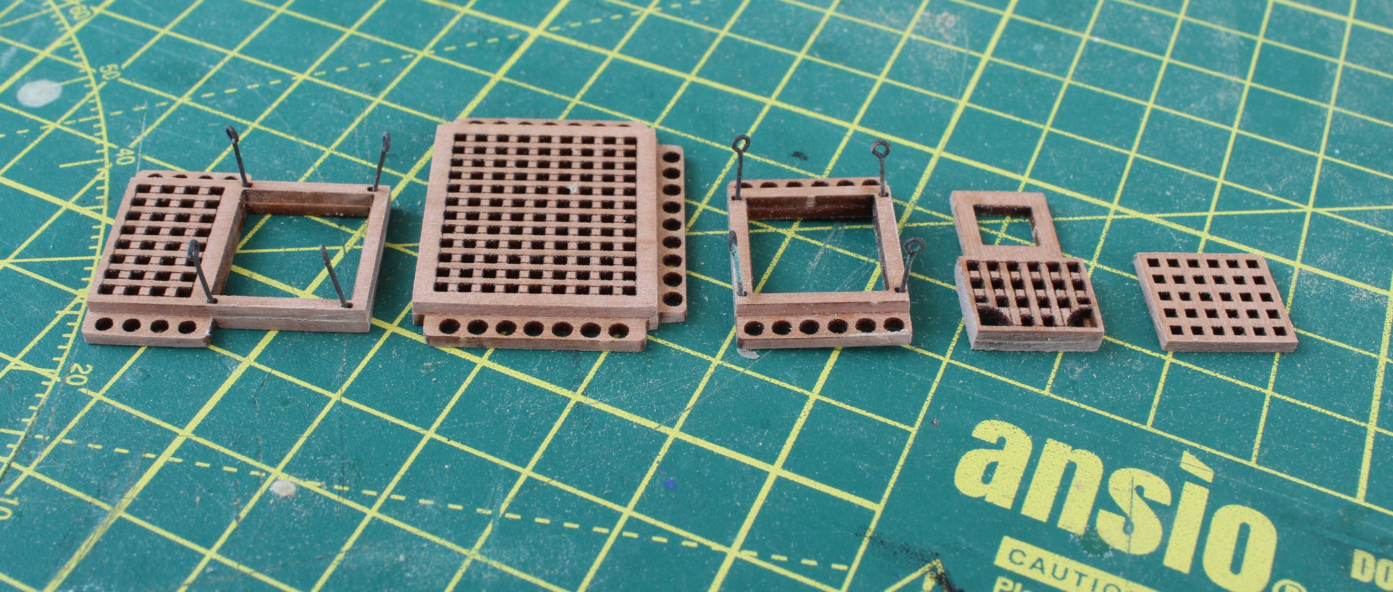
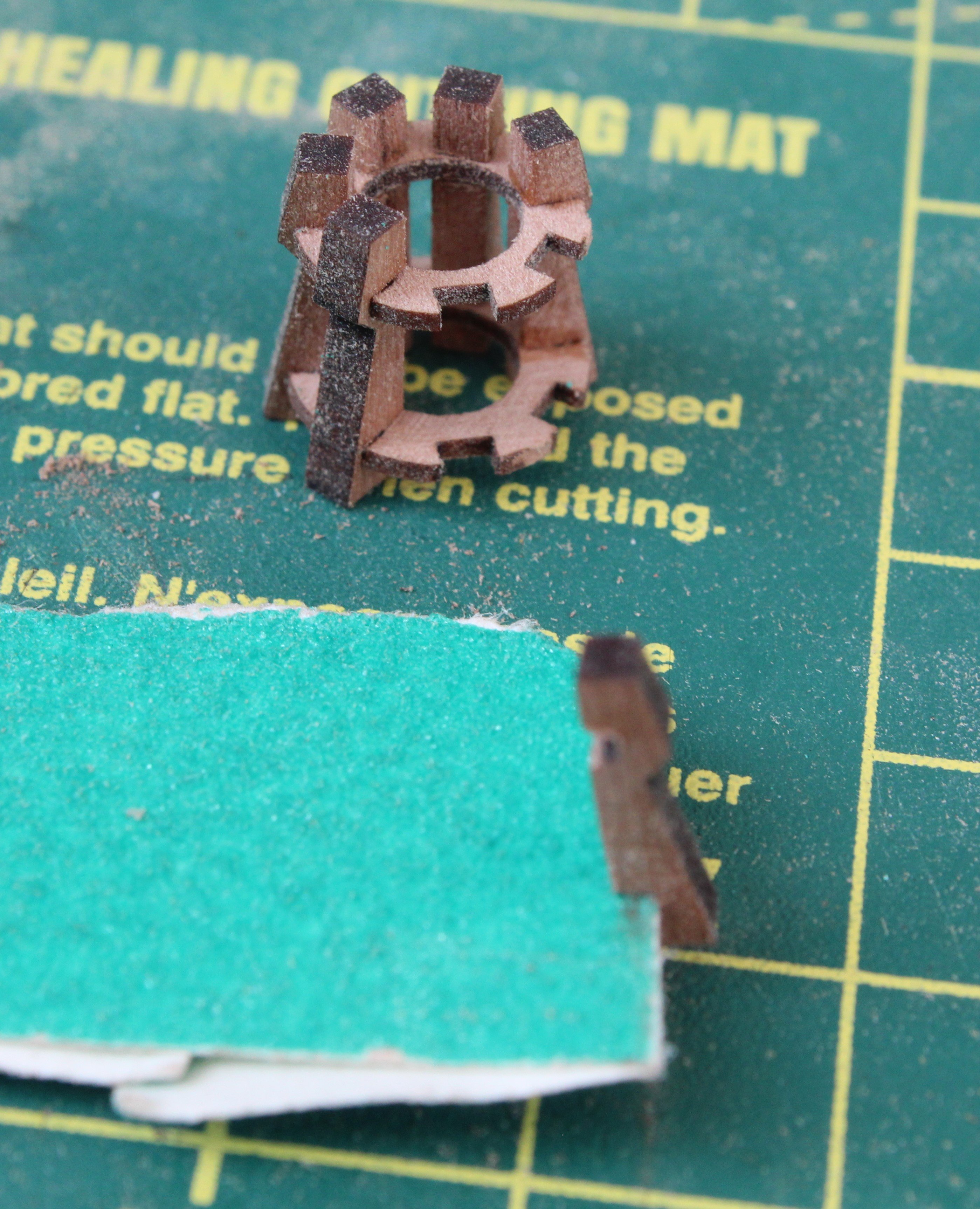
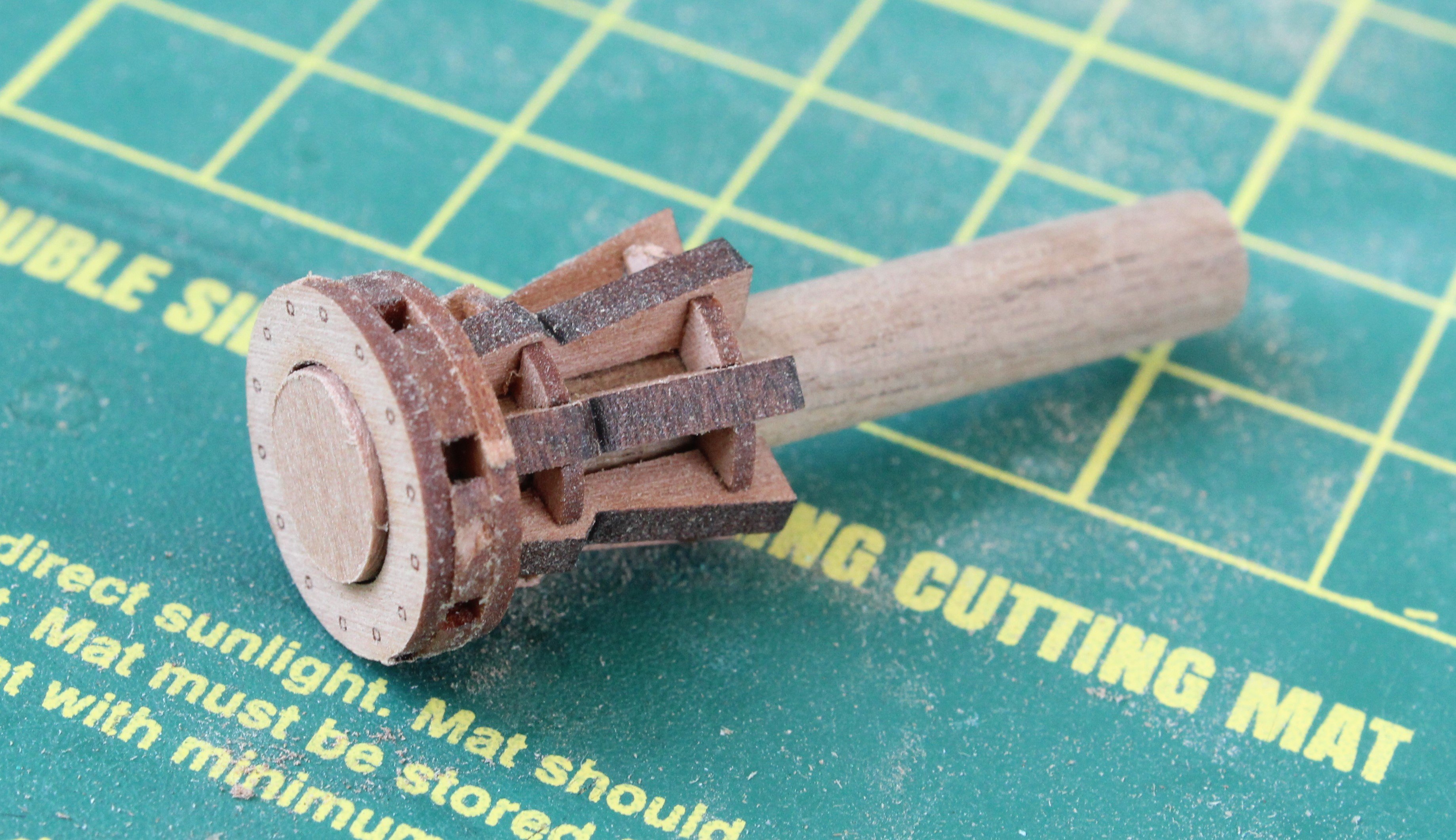
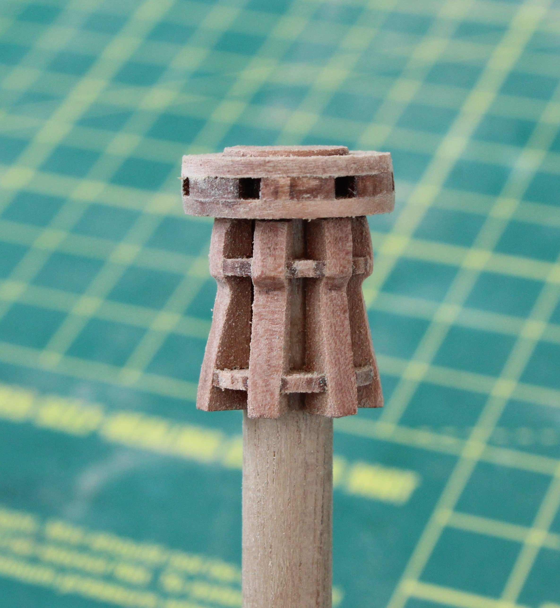
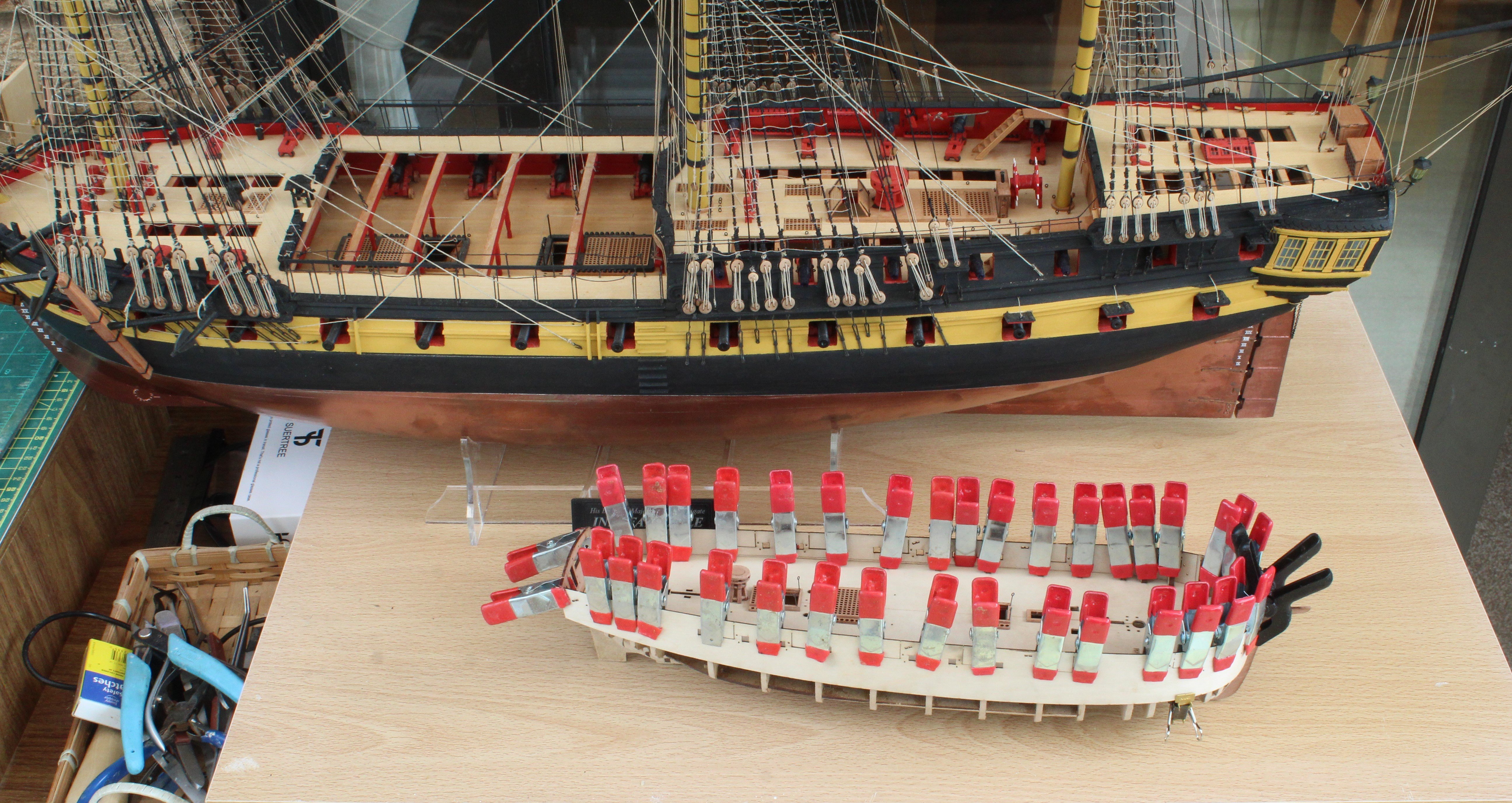
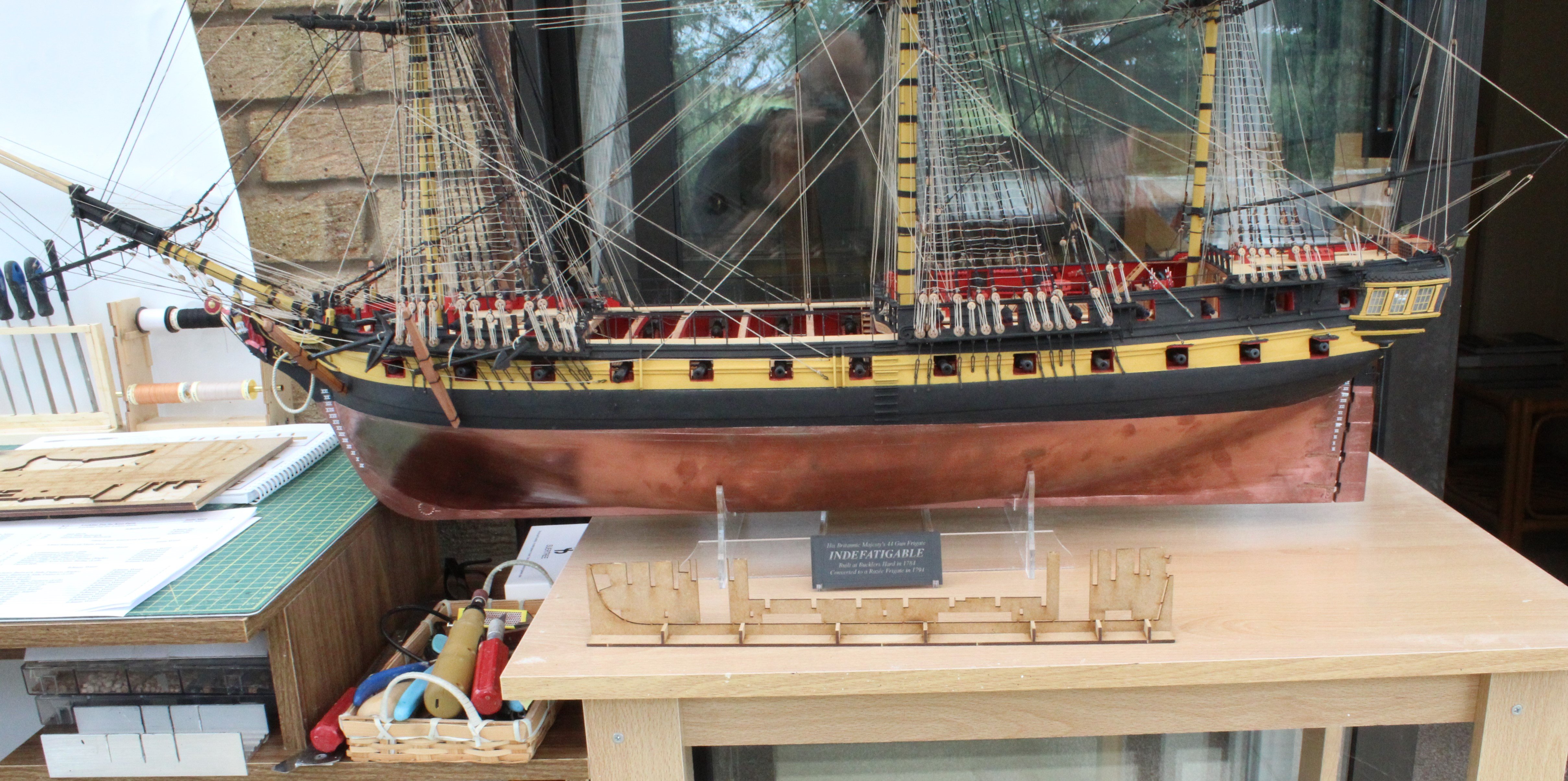
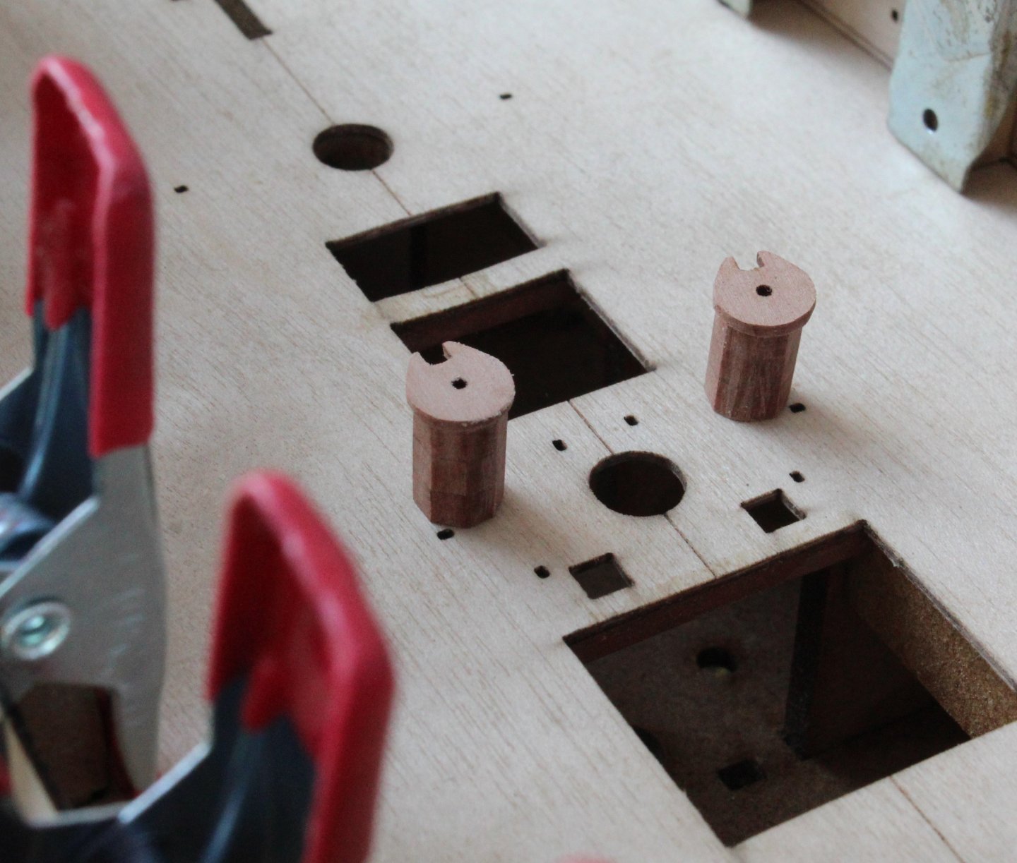
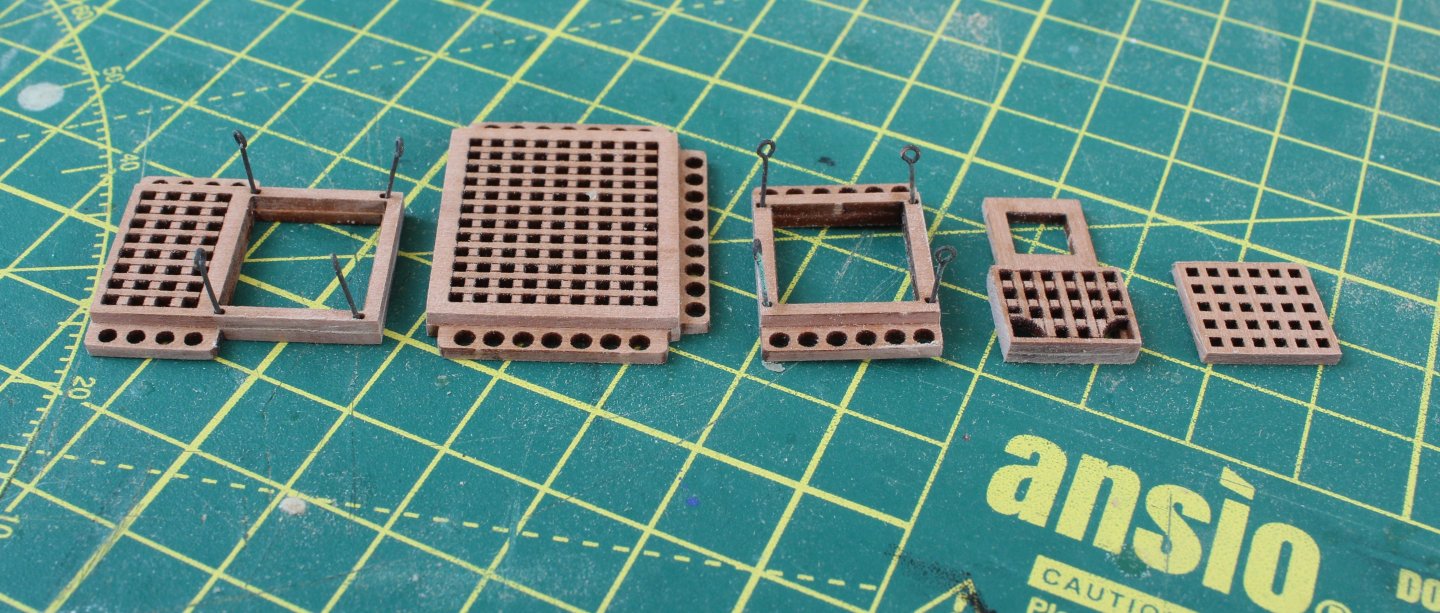
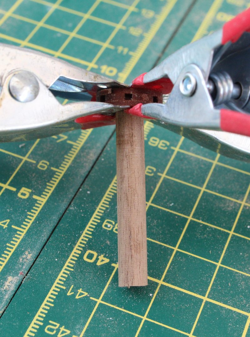
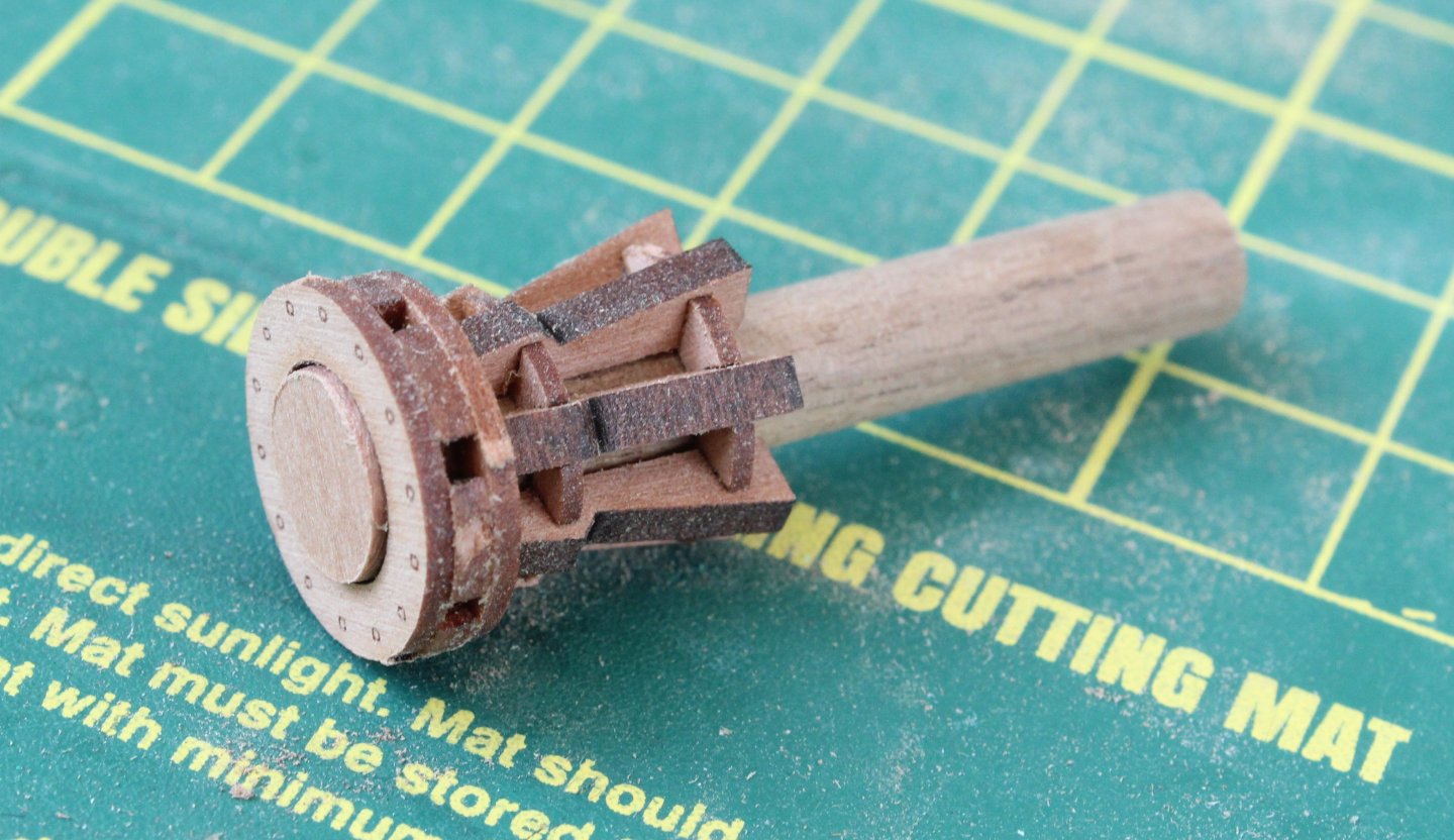
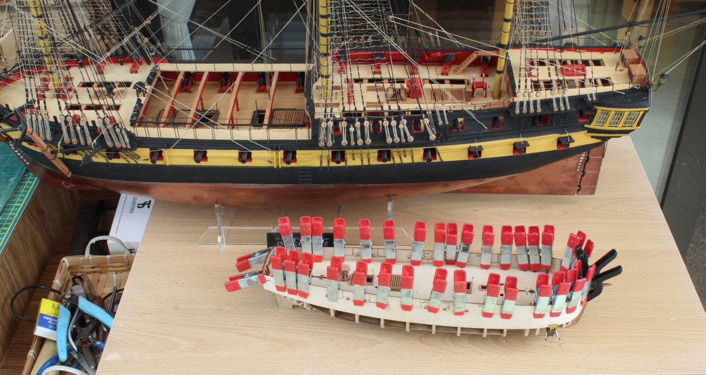
Build Log Index Bulwarks, Deck Coamings and Capstan Date: 15/07/2024 Time worked today: 1 hour. Total time spent on build: 6 hours. Bulwarks After soaking the left and right had side bulwark patterns in hot water for approx. 30 minutes they were pinned to the hull and they will now be left to fully dry out for 24 hours. As can be seen in the attached photos they seem to be a good fit especially around the bow area. Deck Coaming Assemblies There are 5 deck coamings / hatches required for the Adder, namely: a) Fore hatch b) Fore Companion Coaming c) Main Hatch d) Rear Hatch and Companion Coaming e) Stern Grating. Before assembling these items I removed the laser char from the various pieces. The top and bottom pieces glued and clamped, using pins in the rope stanchion holes to ensure they were properly aligned. Capstan Assembly There are 7 off whelps which are inserted into the lower and upper capstan chokes. When I did a trial dry fit I noted the slots in the whelps were too tight, therefore I used some sandpaper to clear the laser char. The whelps were then fitted without any issue. A length of 6mm dowel was cut and the capstan drum parts (lower, centre and upper) were aligned and glued. The capstan drum was then added to the lower section, noting laser char still needs to be removed from all the visible edges. And now a photo after the laser char had been removed. I might paint this assembly flat red or green. The next picture shows the capstan and deck coamings placed on the sub deck. The final photo shows the "mighty" Adder next to the Indy.


-
I look at the rigging runs and belaying points to decide what to rig and when and where possible will follow the sequence in the rigging plans. I find it better to work from bottom to top each topic. E.g. I will rig all yard lifts before moving on to rigging all the braces. I also agree with the advice from Chris in his reply reply.
- 146 replies
-
- 2
-
-
- Adder
- Vanguard Models
- (and 1 more)
-
I used the same Red colour on my Indy and I will also use it on my Adder build. It looks really nice.
- 66 replies
-
- 2
-
-
- Adder
- Vanguard Models
- (and 1 more)
-
Thanks, I am pleased my guide is useful.
-
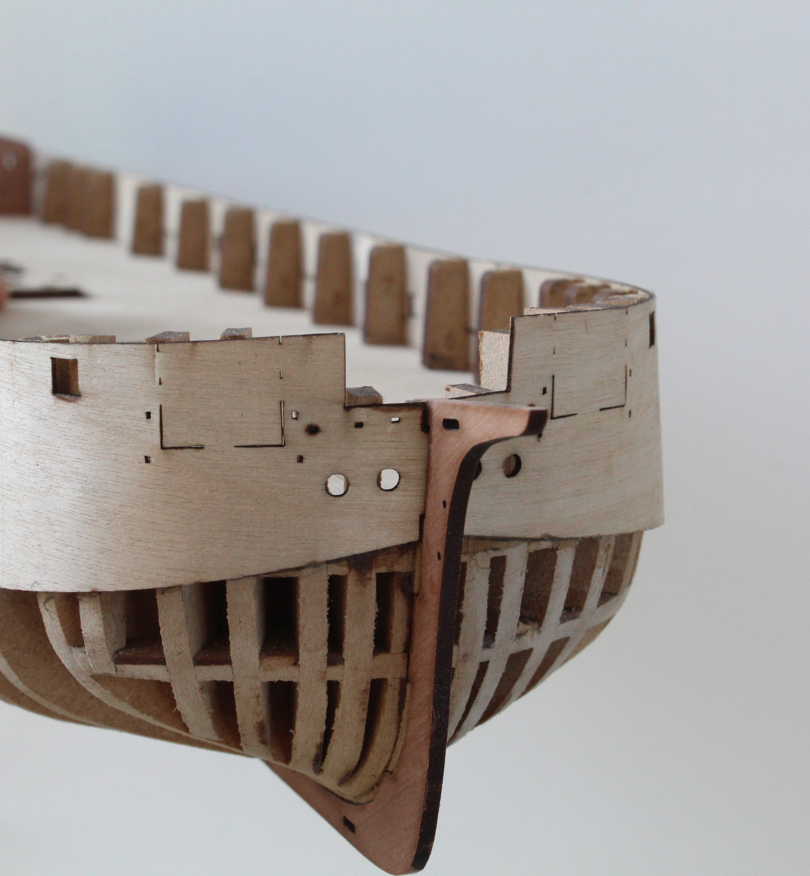
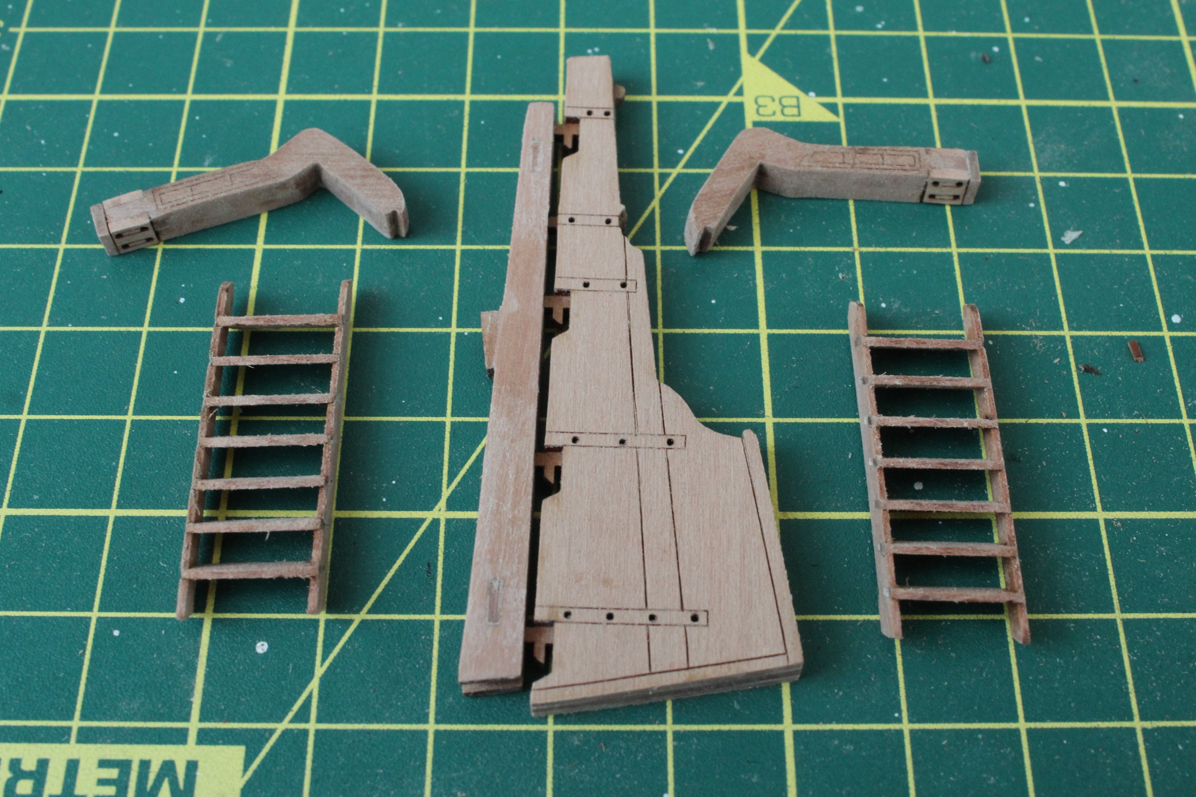
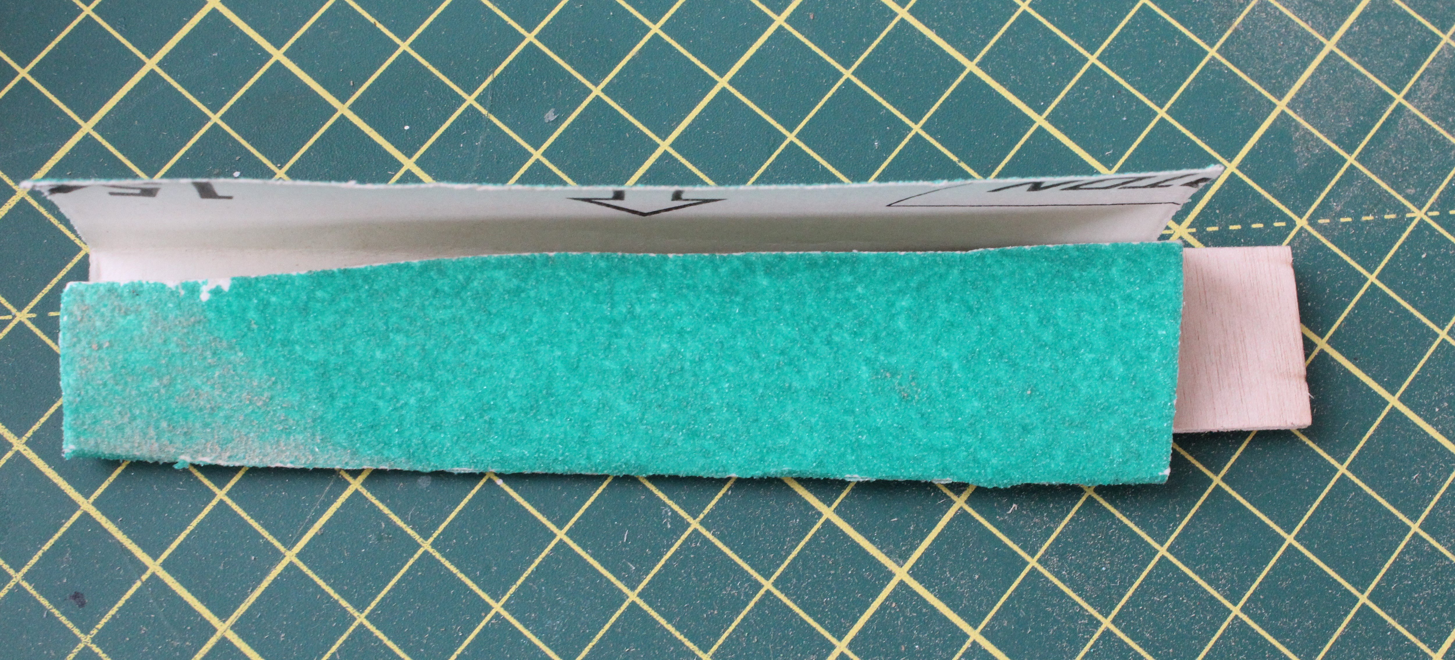
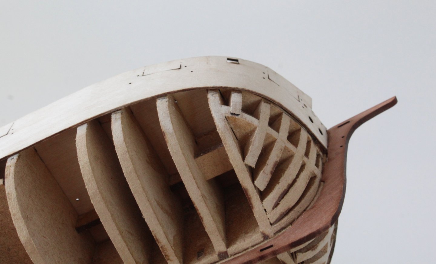
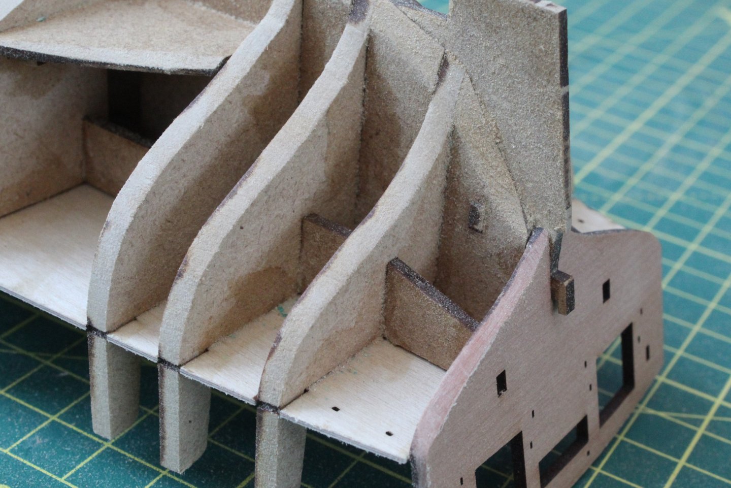
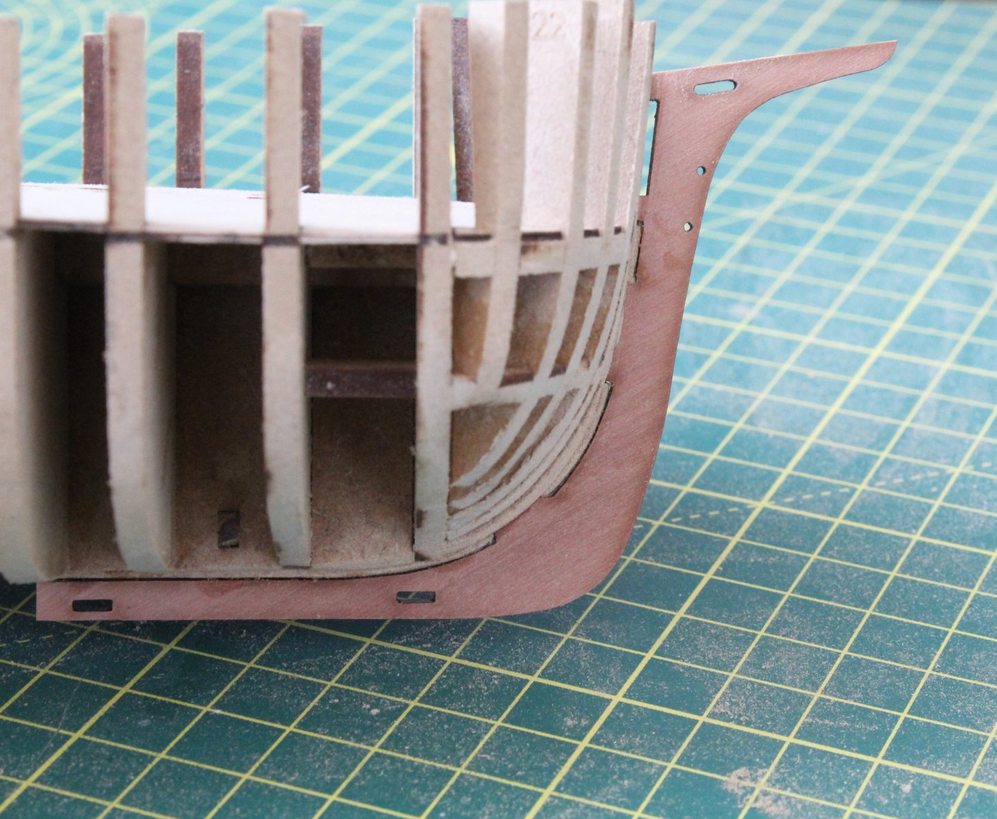
Build Log Index Fairing The Hull Date: 14/07/2024 Time worked today: 2 hours 10 minutes. Total time spent on build: 5 hour. There are quite a few photos attached to this post and in addition to fairing the hull this post will also cover work related to the catheads, ladders, rudder stern post and prow. I decided I would make a start on some of the deck items and assembled both the catheads and ladders. I also assembled the rudder / stern post and rudder. There is a locating peg to ensure the outer patterns for the rudder / stern are properly aligned. I used some brass pins in the hinge holes to ensure the outer patterns for the rudder were correctly aligned. I did make sure t remove the laser char, where appropriate from these assembled items. The tabs on the keel support jig were then cut and the excess tab material removed from the hull. In preparation for the fairing I took the advice in the build manual and wrapped some sandpaper (120 grit) around a length of scrap 0.8mm material I took my time and faired one side of the hull. Using some spare 0.8mm material to represent the bulwark a check was made on how the fairing looked. I was really pleased with the flow of the test material and there is good full contact on all the bulkheads and bow frames. I used a thin sanding stick to check the flow of the stern section which also looked good. It was then a case of repeating the process on the other side of the hull. Next the prow assembly was test fitted and there was allround good contact with the keel. After the leading edges of the prow bolsters were chamfered the prow assembly was glued in place. The final task of the day was to test fit both the port and starboard bulwarks. I started with positioning the bulwarks at the stern end and using the guide lines provided started to clamp them in position. Everything was lining up perfectly. As I started to bend the bulwarks around the bow area I felt there was too much resistance and feared they may snap in two. I think it will be better to soak them in some hot water for 30 minutes and them to clamp them in place, leaving the bulwarks to fully dry out. As indicated in the build manual this may take several dry fits before they are ready to be glued in place.


-
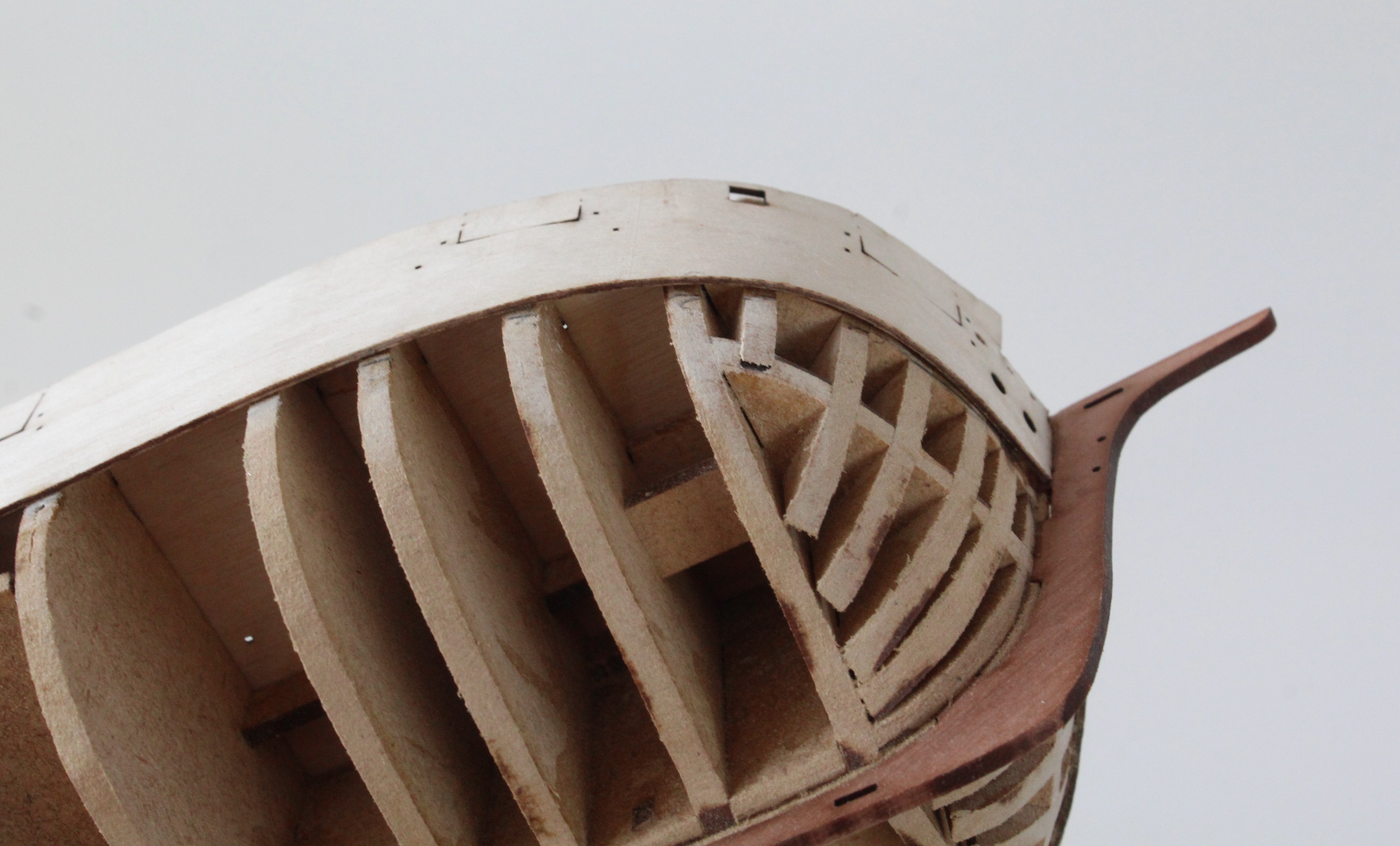
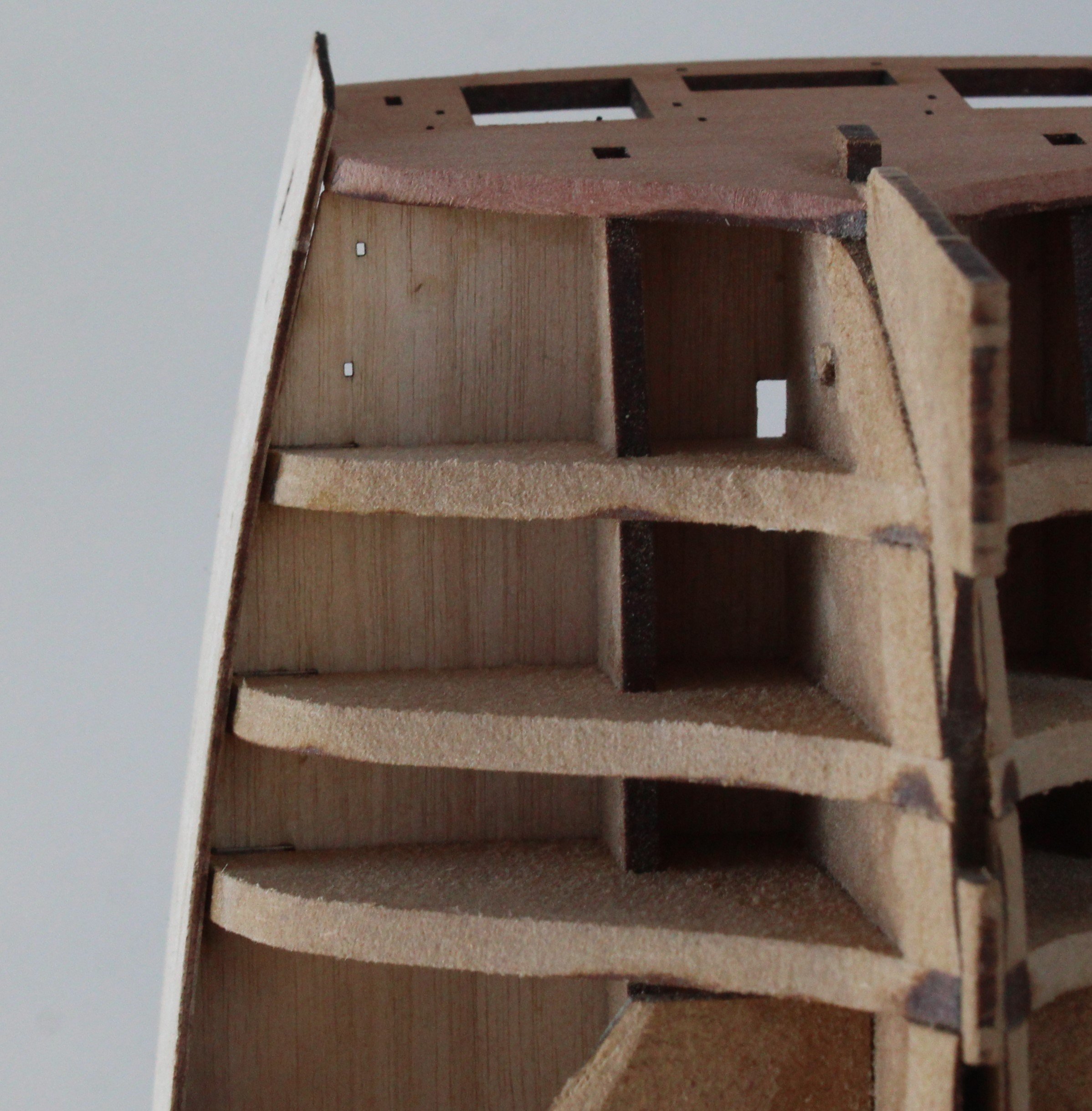
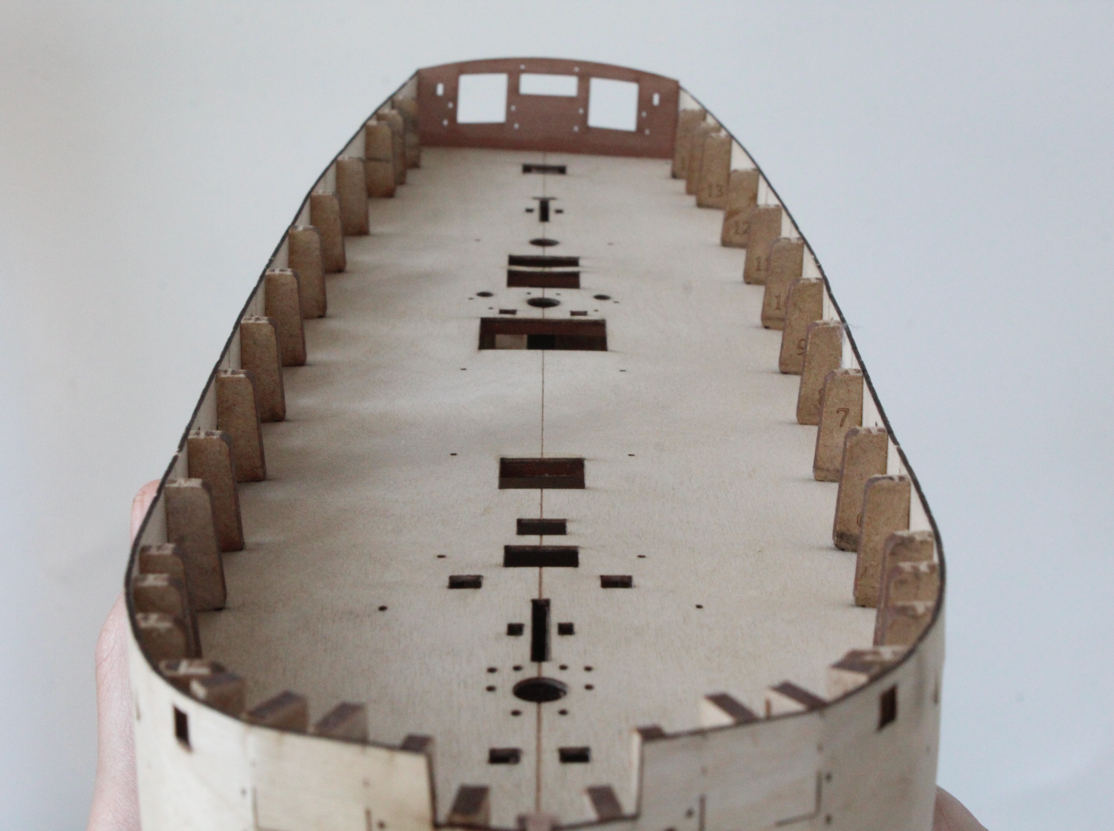
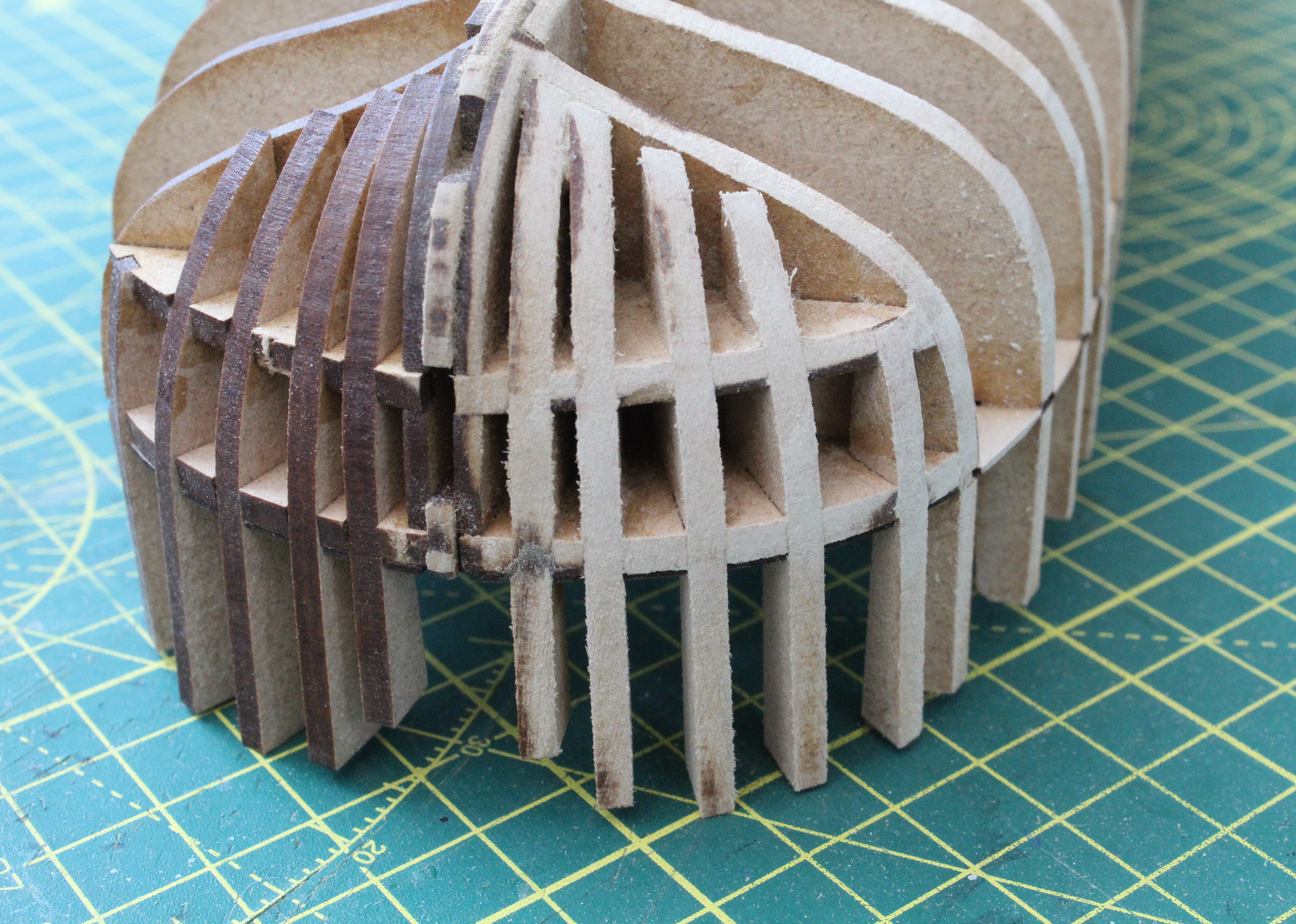
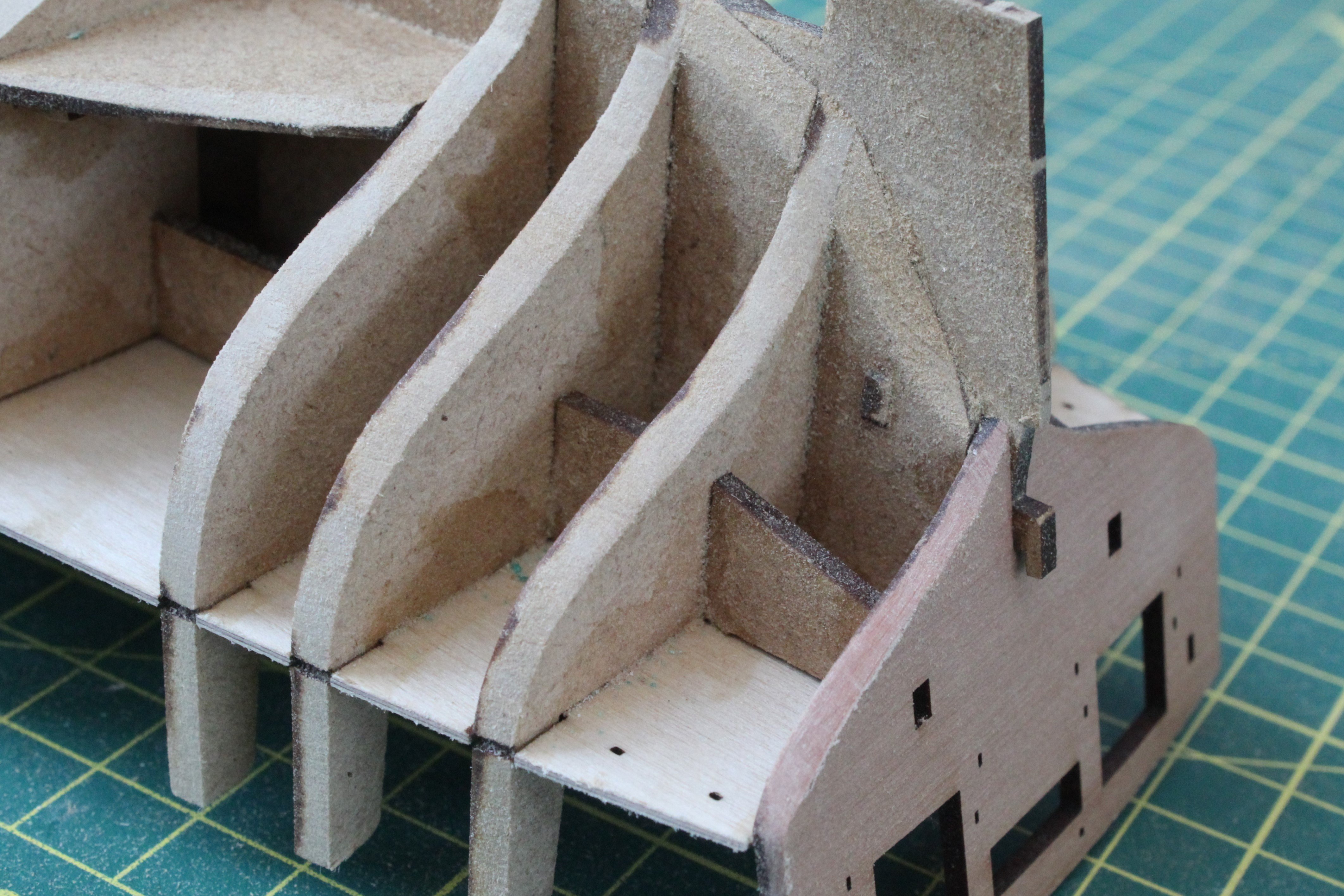
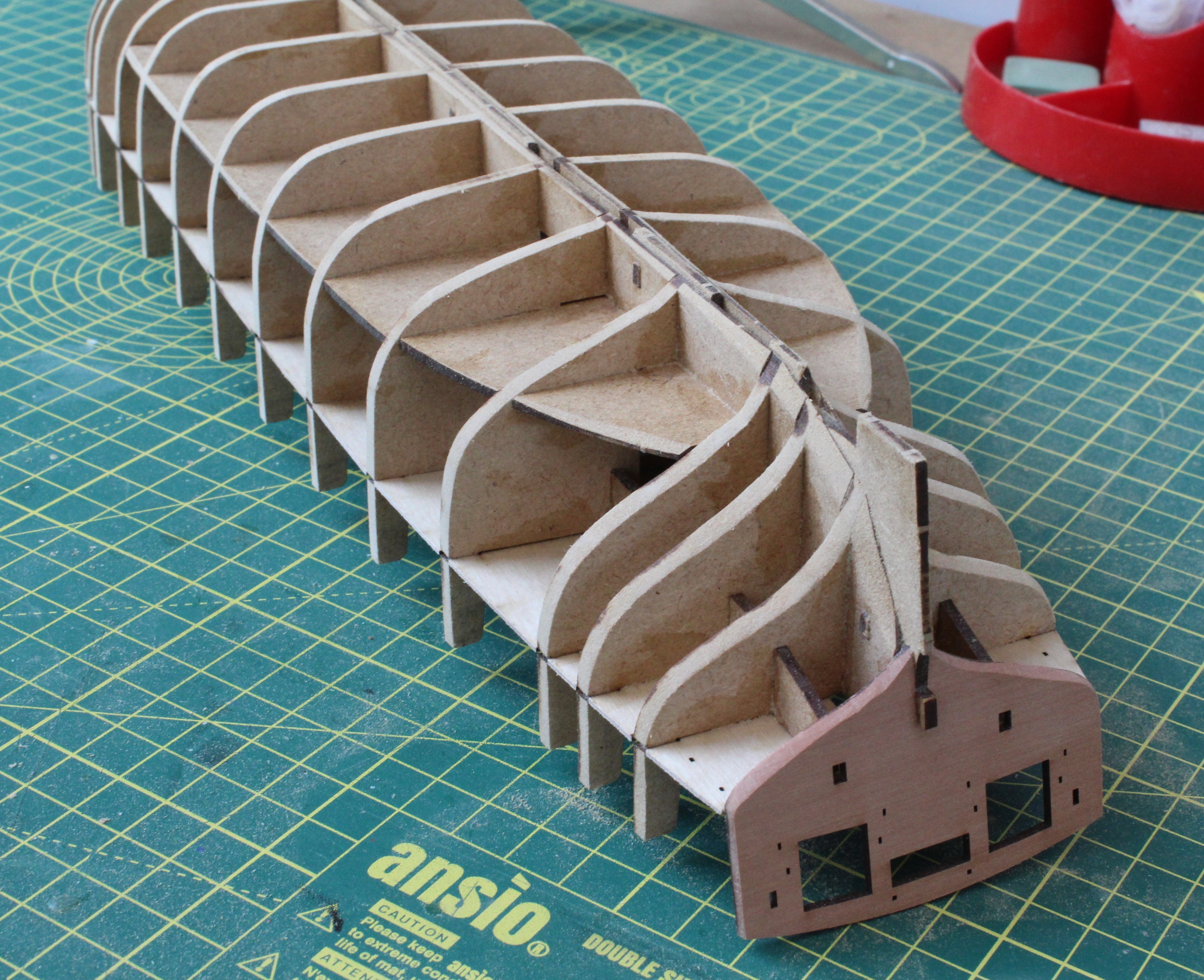
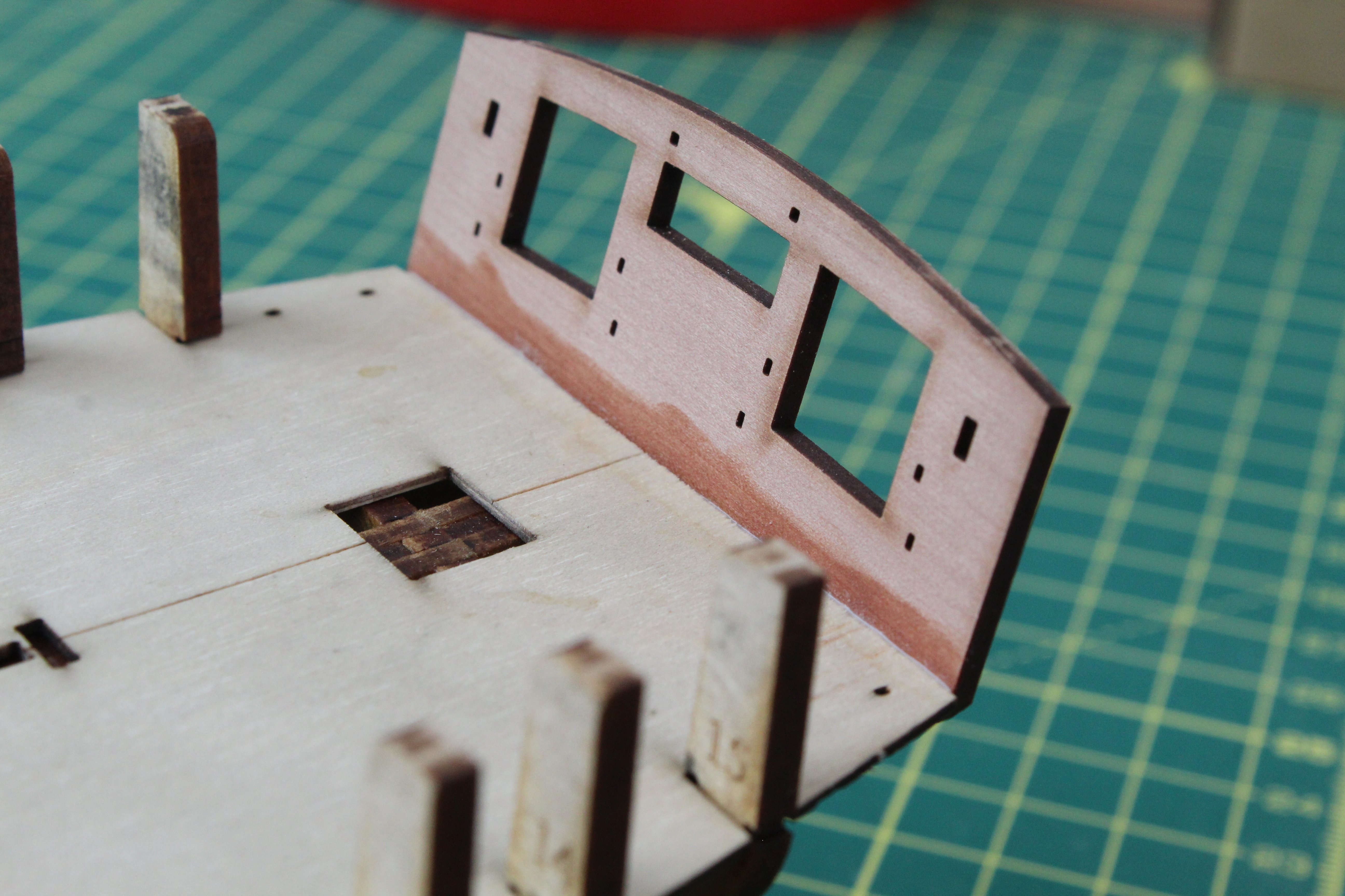
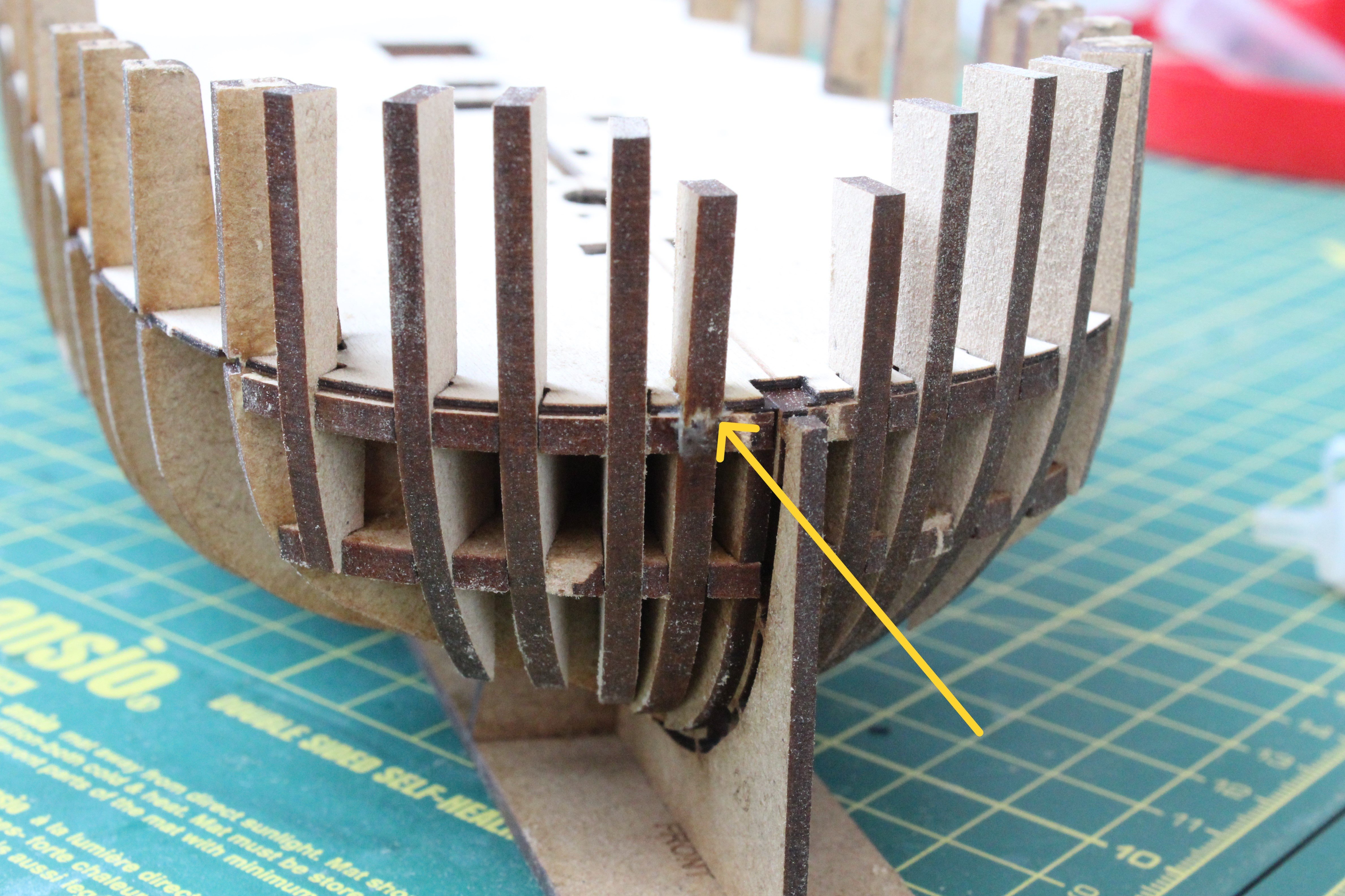
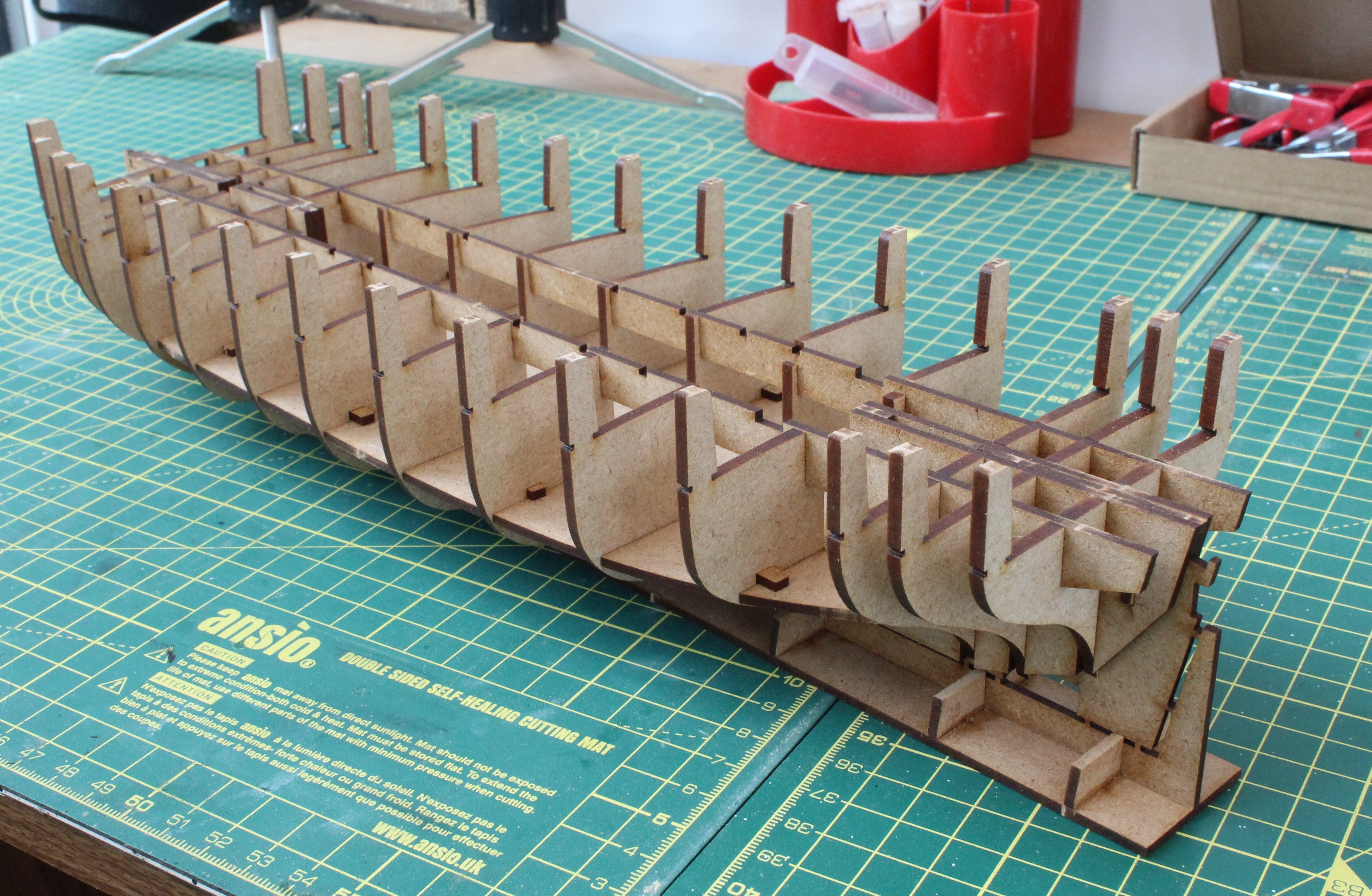
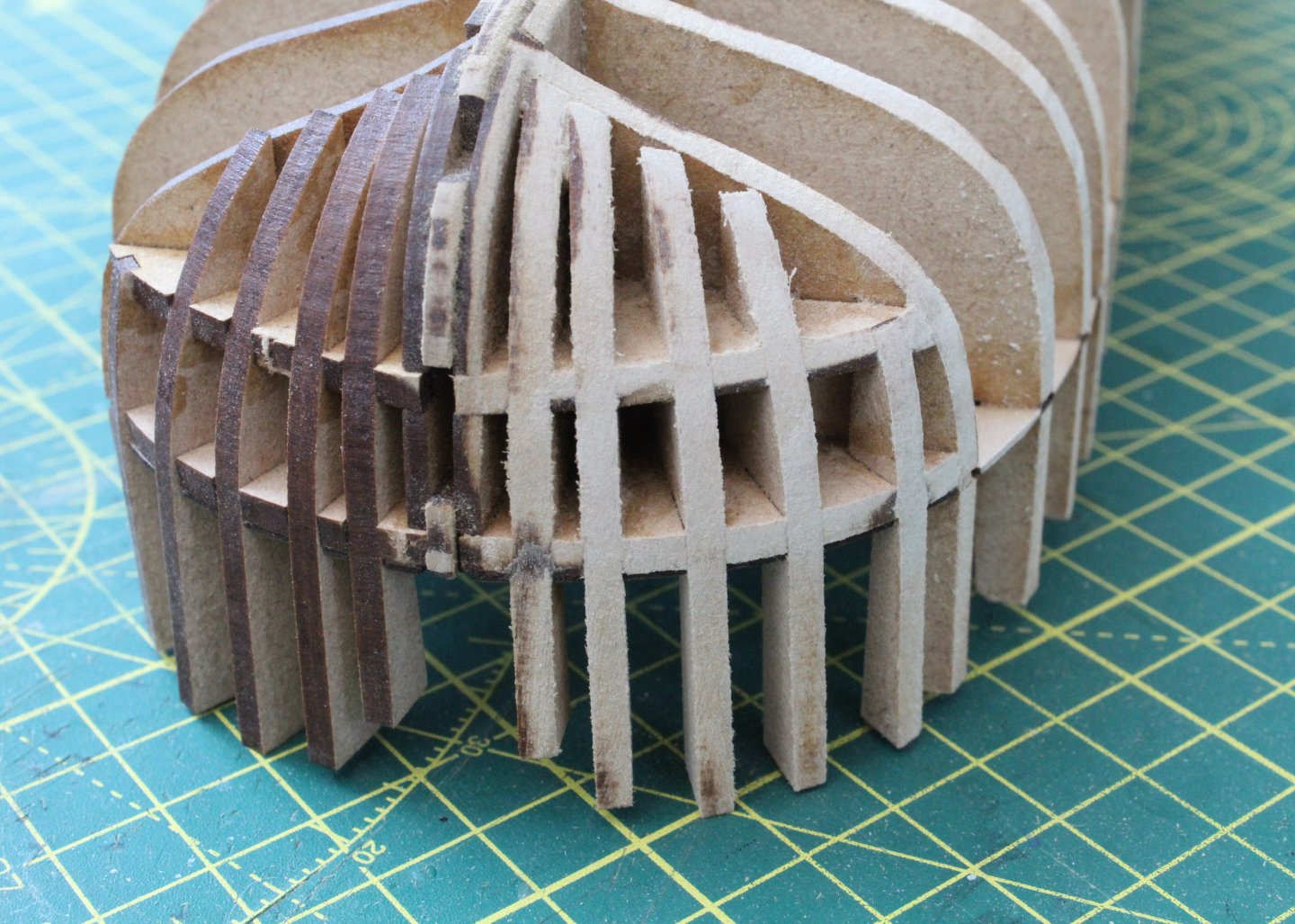
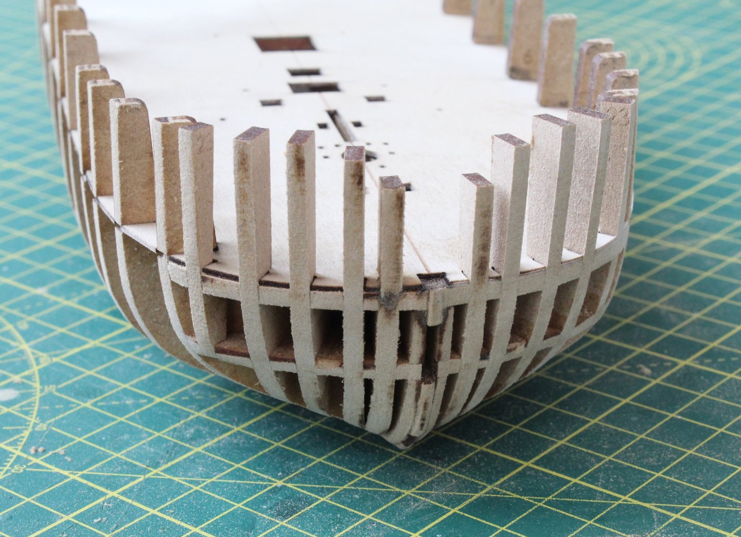
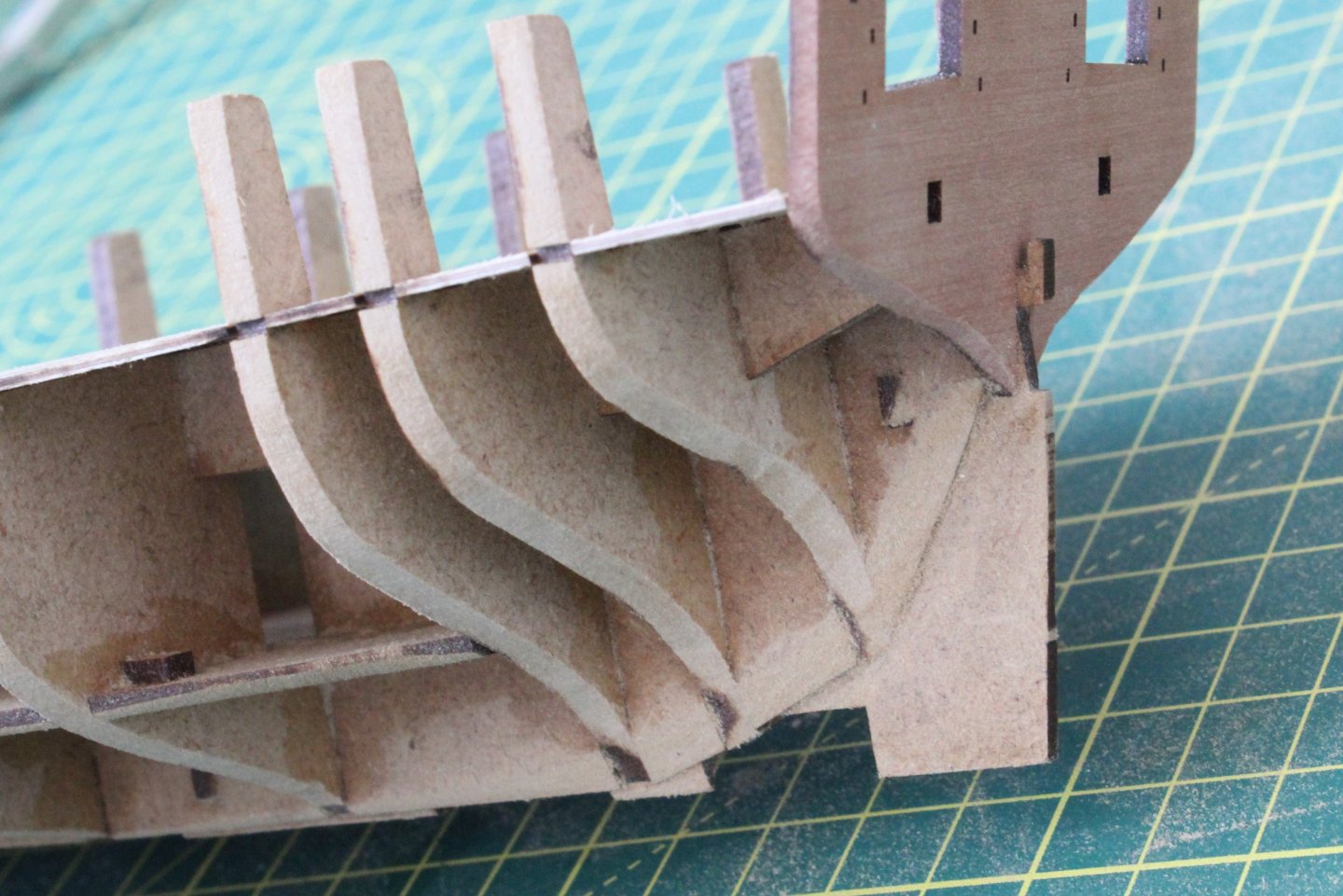
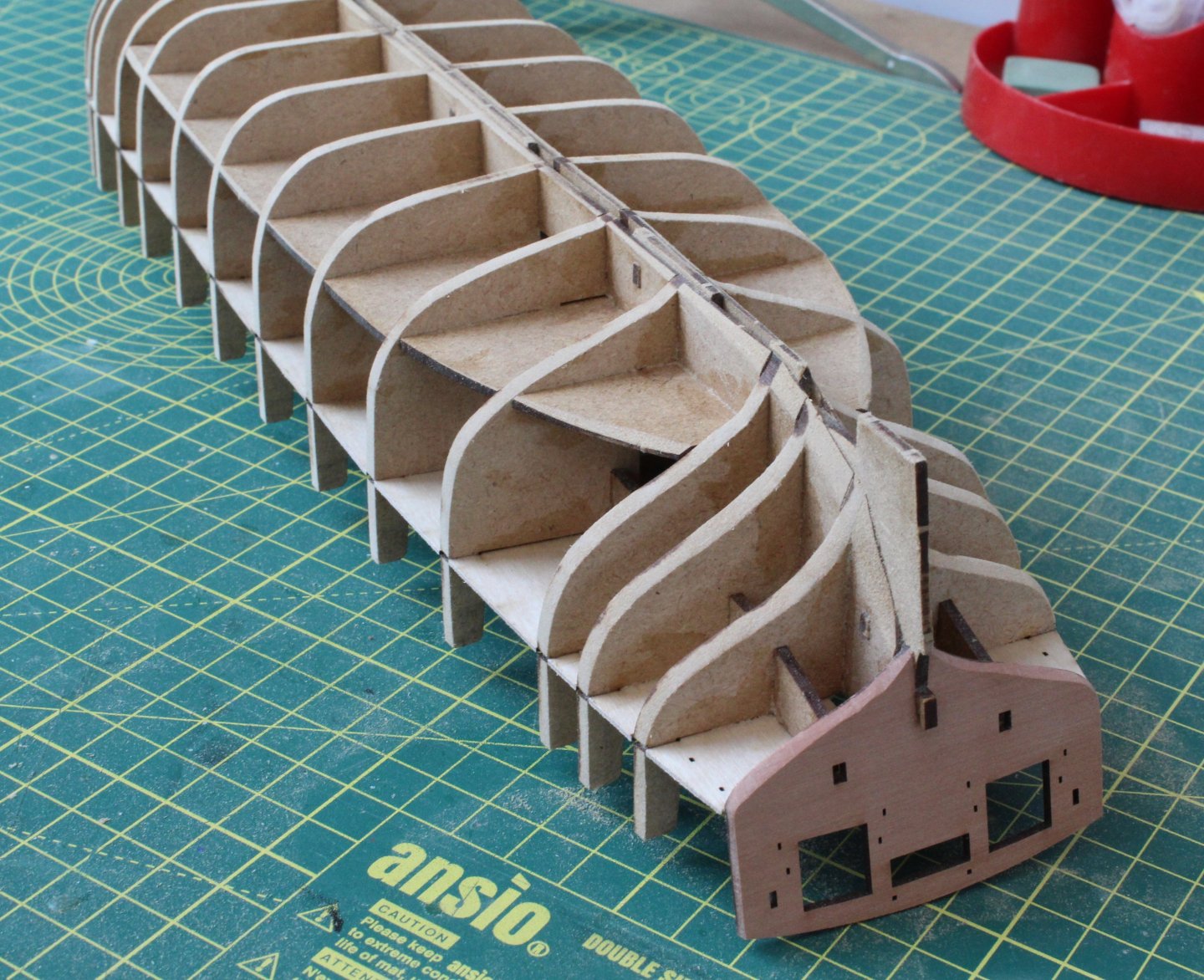
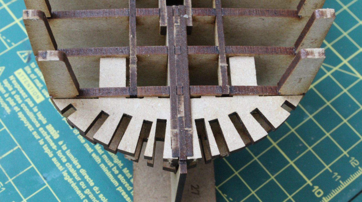
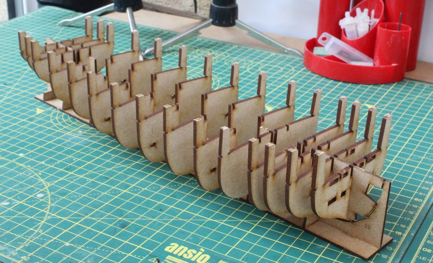
Build Log Index Hull Construction Part 3 Date: 13/07/2024 Time worked today: 1 hour 30 minutes. Total time spent on build: 2 hour 50 minutes. With regards to the lower and upper horizontal bow frames once I had filed away some of the laser char I was much happier and proceeded to glue them in place. I then removed the excess material from the aft end of the sub deck. Before gluing the sub deck to the framework I also removed the laser char from all the various openings. Once that was complete wood glue was applied to all the deck beams and bulkheads, noting not to add glue to the upper horizontal bow frames. The sub deck was gently bent and pushed in to place without any problems. As indicated in the build manual there is a nice satisfying click as the sub deck engages into the various bulkhead securing slots. I did use a few clamps to hold the central section of the sub deck in place as the glue was curing. After a couple of hours to allow time for the wood glue to cure (not fully) all the bow cant vertical frames were then added. I did have a mishap when installing the inner most bow cant vertical frame on the right hand side when the upper tab snapped off. I was able to glue it back in place and I hope it will be ok when the bow section is faired. Once the bulwarks have been fitted the bulkhead tabs will be removed before the laser engraved deck is fitted. The final task undertaken was to apply watered down wood glue to all the bulkhead joints which will now be left for approx. 18 hours to allow time for the wood glue to fully cure. The basic hull construction work is now complete and the next phase will be fairing the hull in readiness for the first planking.


-
Build Log Index To help me (and fellow builders) navigate through this build log I keep an index of the various sections, complete with a hyperlink to the relevant posts. Hull Construction Part 1 Hull Construction Part 2 Hull Construction Part 3 Bulwarks, Coamings and Capstan Preparation for first planking Bulwarks and Galeon Andalucia First planking - Fitting The Master Plank 24-Pound Cannon Assembly Start of First Planking How Not To Fit A Stealer First Planking Sanding The Hull After 1st planking Pre Second Planking Work Second Planking Start and Carronades Start of Second Planking, Garboard Plank and Carronades Second Planking Completed Sanding, Filling and Painting the Hull Painting The Hull Continues Fitting Outer Bulwarks and Test Fit Deck Fitting Inner Bulwarks and Test Fit Deck Items Fitting Inner Stern Transom Pattern Spirketting Gunwales and Bow Timbers Steps, Stern Surround Pattern and Catheads Hawse Hole Bolster, Ships Wheel, Drop Keel Winch and Ladders Hand Pumps, Drop Keel Winches, Belay Pin Racks and Forward Hatch Channels Cannons and Carronades Breach Rope Part 1 Cannons and Carronades Breach Rope Part 2 Main and Fore Mast Manufacture Main and Fore Mast Platform Work Main and Fore Topsail Mast Manufacture Yard and Bowsprit Manufacture Part 1 Yard and Bowsprit Manufacture Part 2 Yard and Bowsprit Manufacture Part 3 Yard and Bowsprit Manufacture Part 4 Bowsprit Installation Hammock Cranes Shroud Deadeye Installation Method and Failure Fore Shroud Deadeye Rework Main and Fore Mast Shroud Deadeye Lower Mast Stays Main Mast Stays, Topsail Masts and Jibboom Guys Topsail Mast Shrouds Part 1 Topsail Mast Shrouds Part 2 Topsail Stays Futtock Staves and Catharpins Shrouds, Ratlines, Stays and Backstays Driver Boom Running Rigging Final Post
-
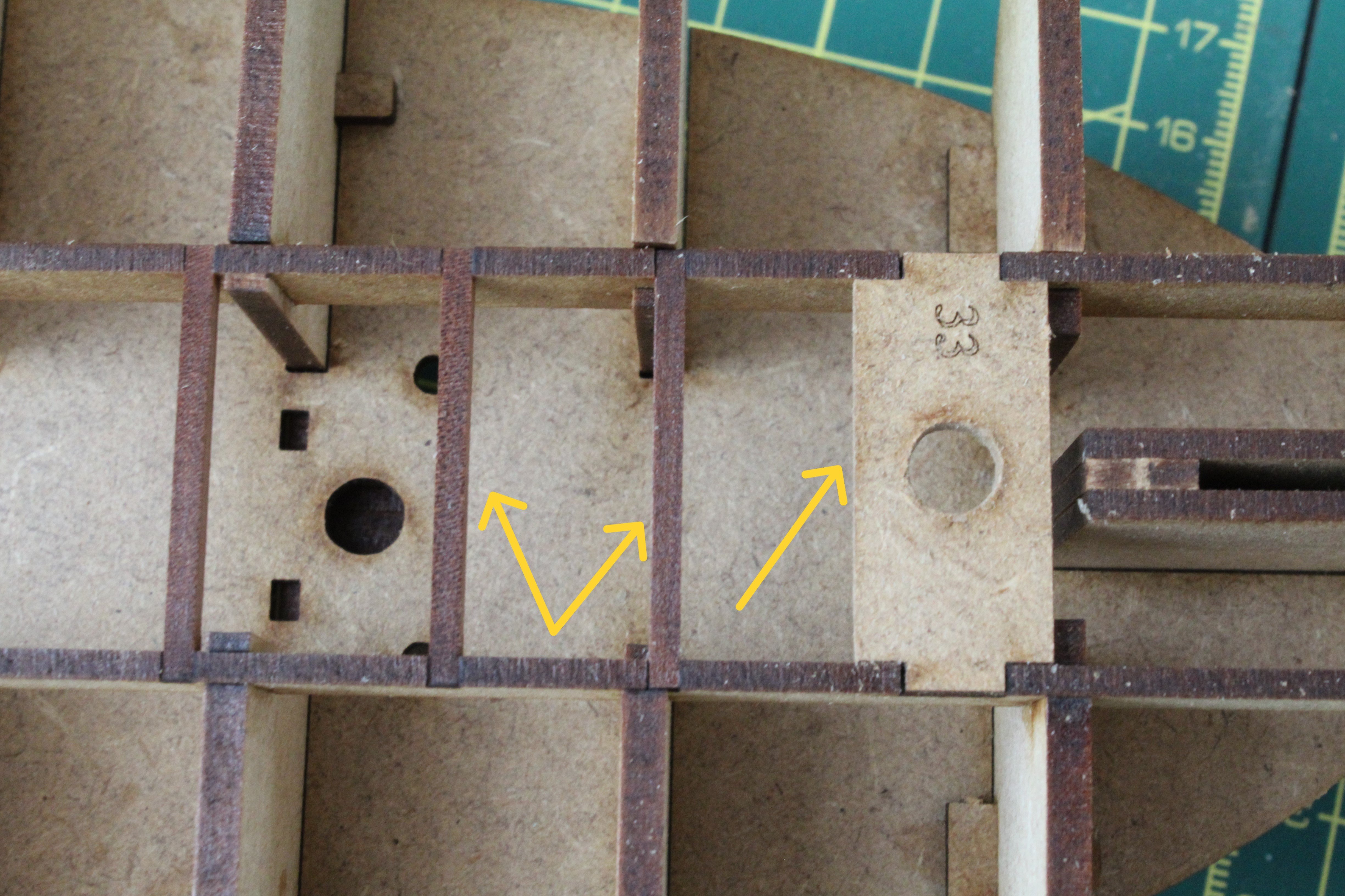
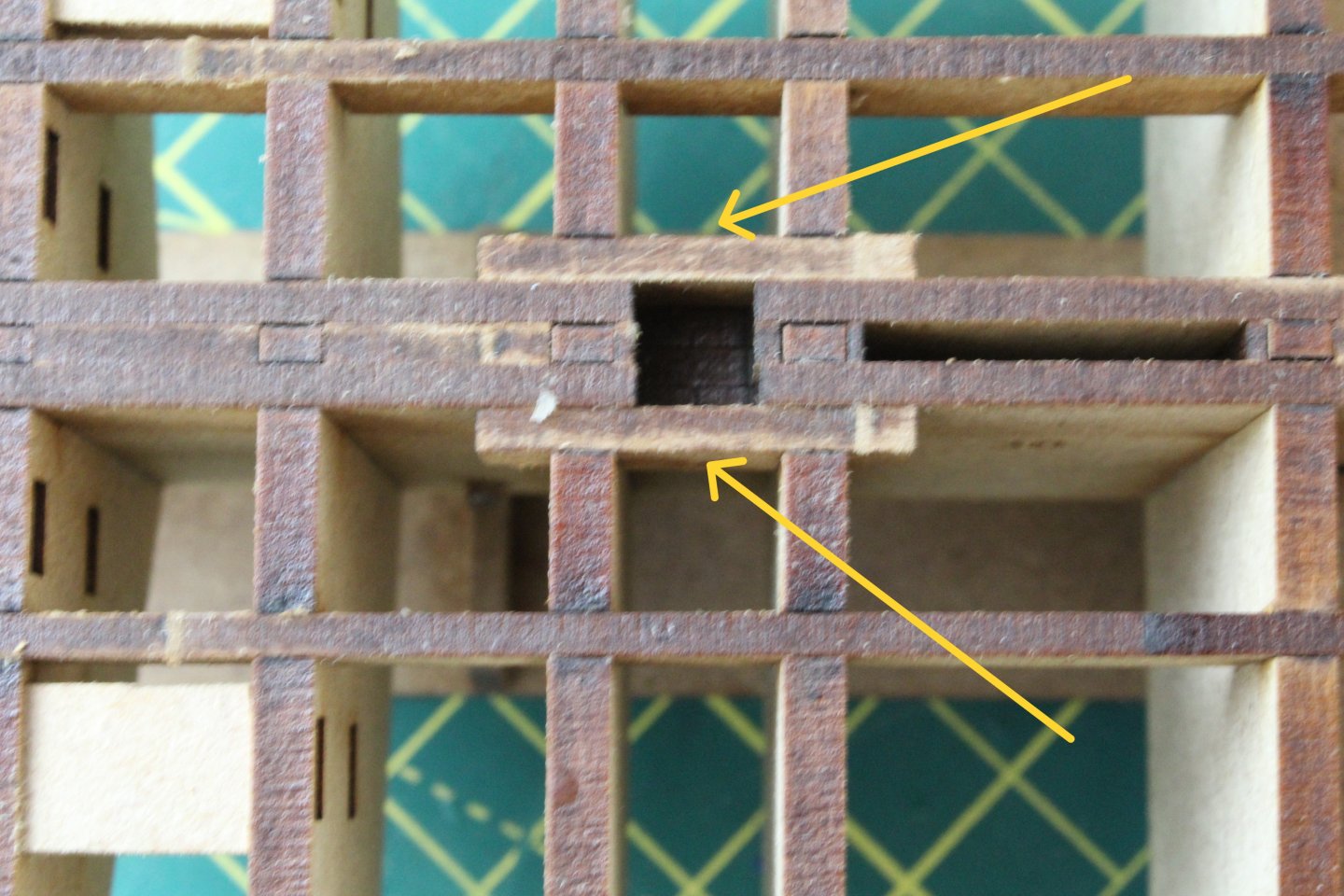
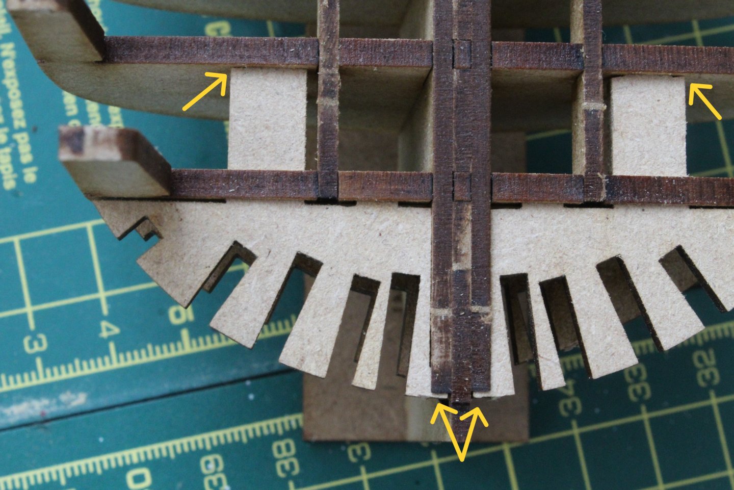
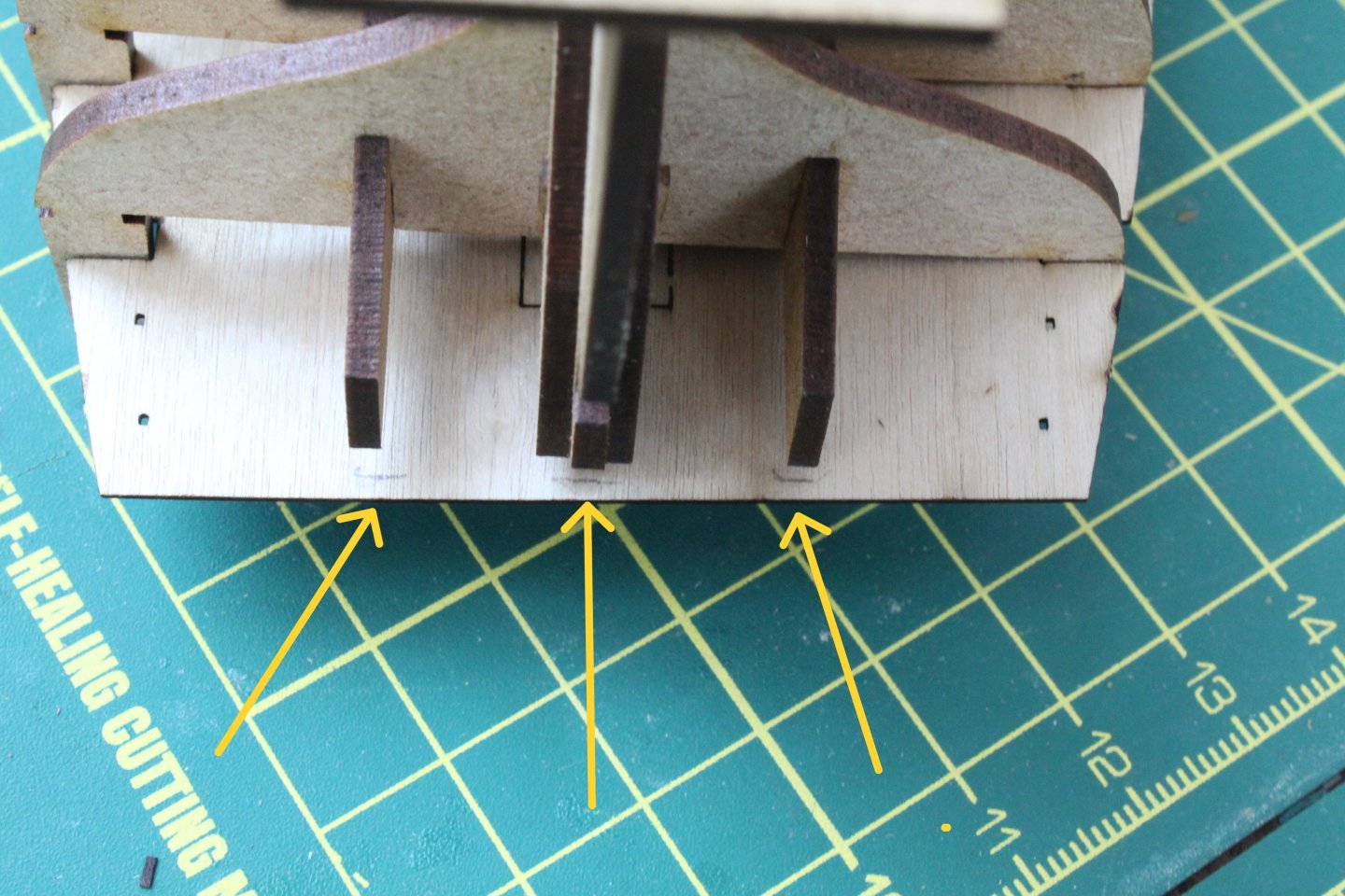
Build Log Index Hull Construction Part 2 Date: 12/07/2024 Time worked today: 30 minutes. Total time spent on build: 1 hour 20 minutes. I was able to be spend 30 mins in the shipyard this morning before the arrival of one of our young grandsons and was pleased with the progress I was able to make. I started by locating and installing the capstan support board and 4 off deck camber beams (aft). After an initial trial fit they were glued in place. Next the 2 off deck camber beams (mid) were dry fitted and then glued in place. The 2 off foremast support checks were the next parts that were dry fitted and then glued in place. Next the 2 off bow frames (lower horizontal) and the 2 off bow frames (upper horizontal) bow frames were dry fitted. My initial impression was they were a good fit. On a closer examination of the dry fit there is still a little bit of adjustment work required as the parts do not fully engage. I need to adjust all the longer tabs, which butt up against bulkhead 2. I could accept the fit knowing this will not be an issue once the bow area has been properly faired but I will ensure I have a better fit before gluing these parts in place. I have also dry fitted the various bow ‘cant’ frames (vertical) and they all seem to be a good fit. Finally, I did a test fit of the sub deck and, as @DB789 (Dan) noted in his build log, there is a small overhang of the sub deck which needs trimming, as can be seen in the next photo. It will be easier to trim the sub deck before installation.


-
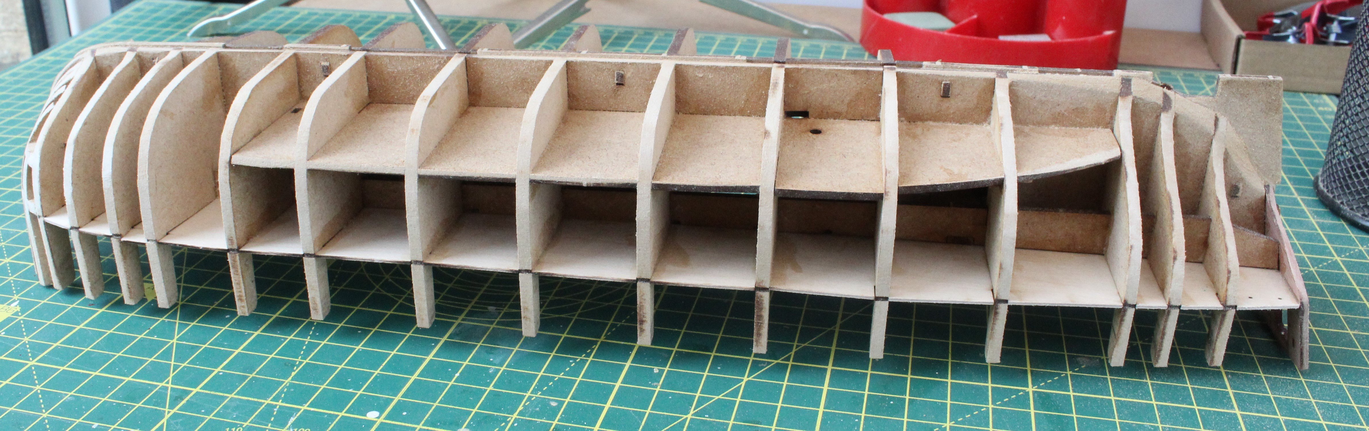
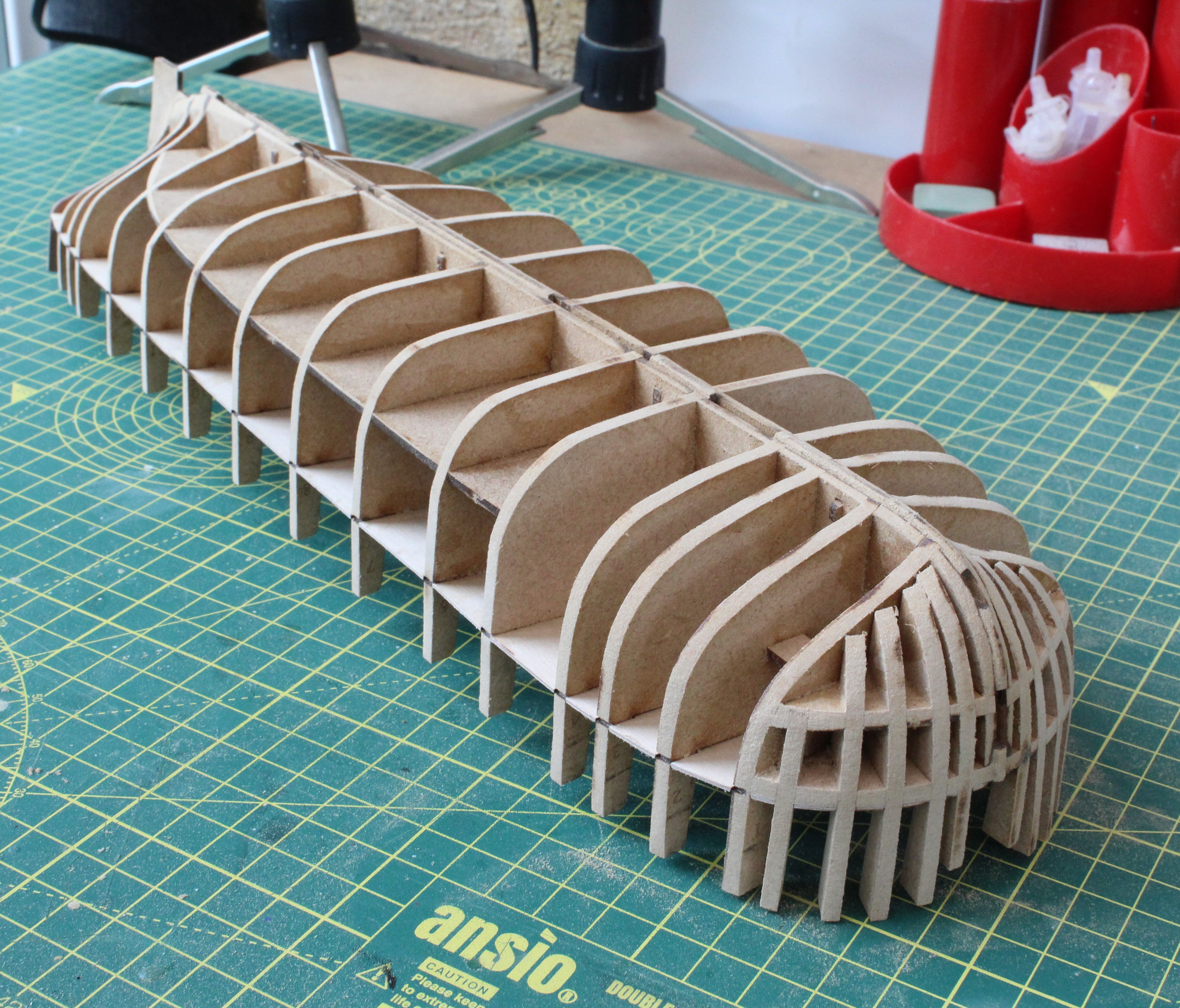
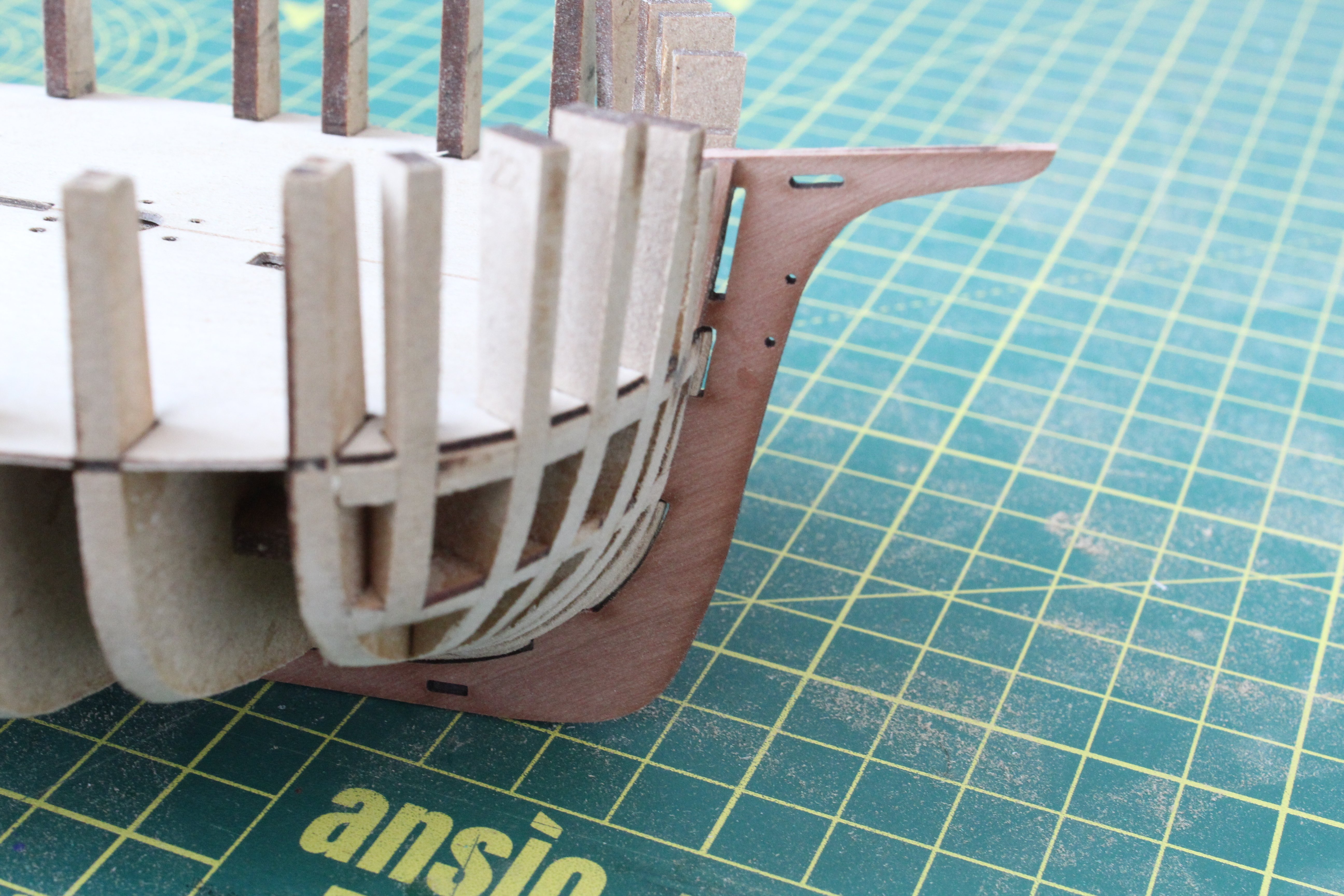
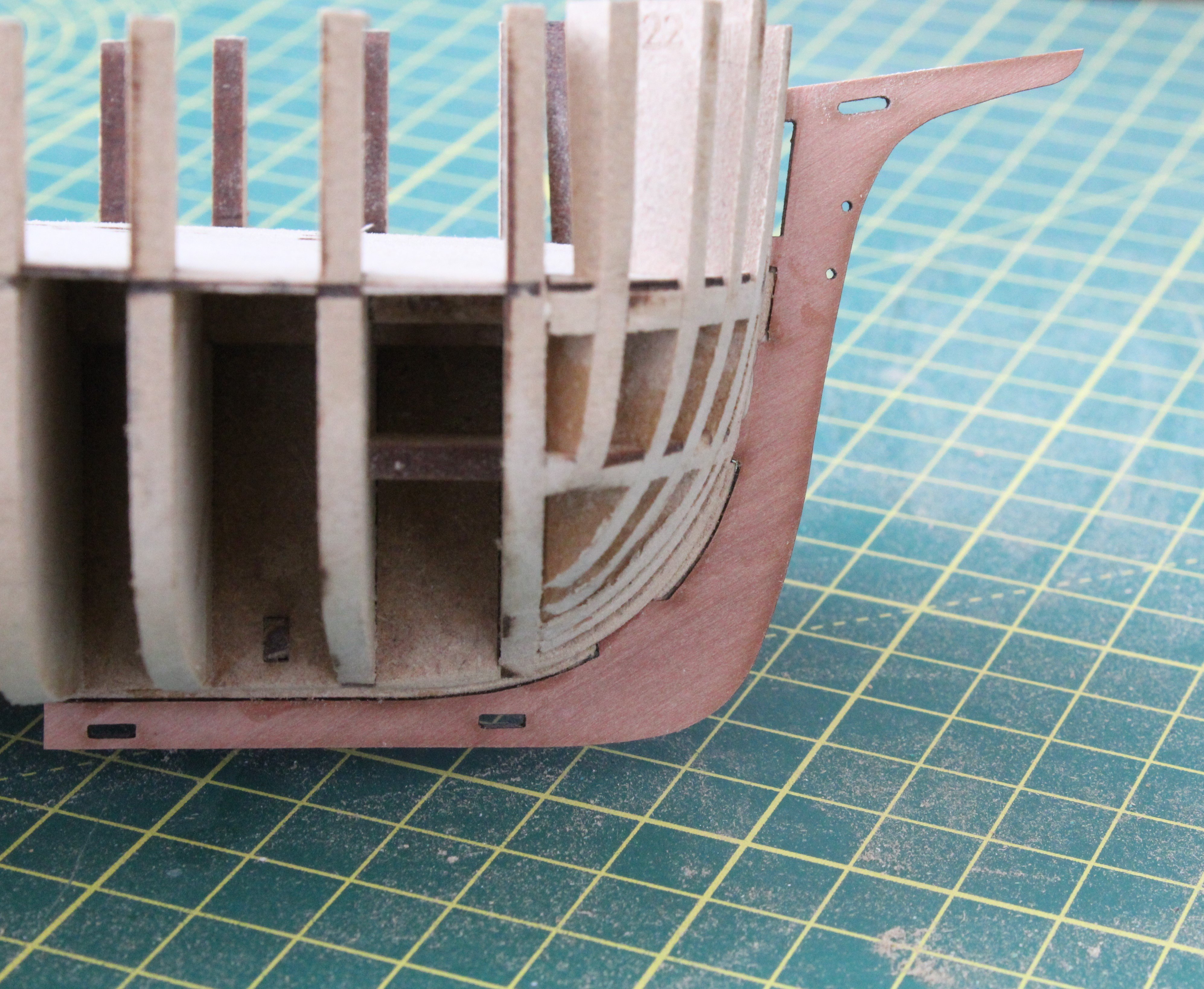
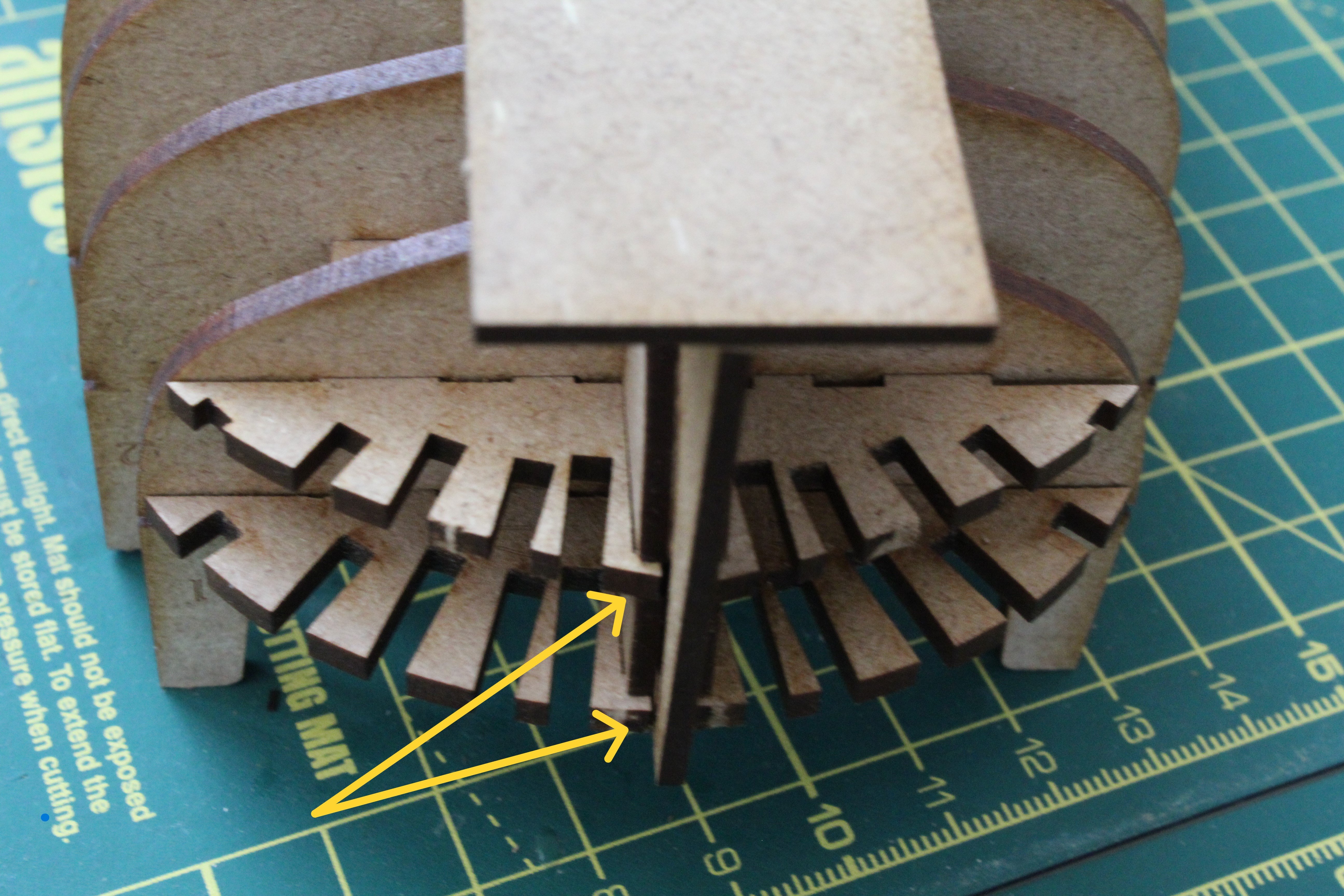
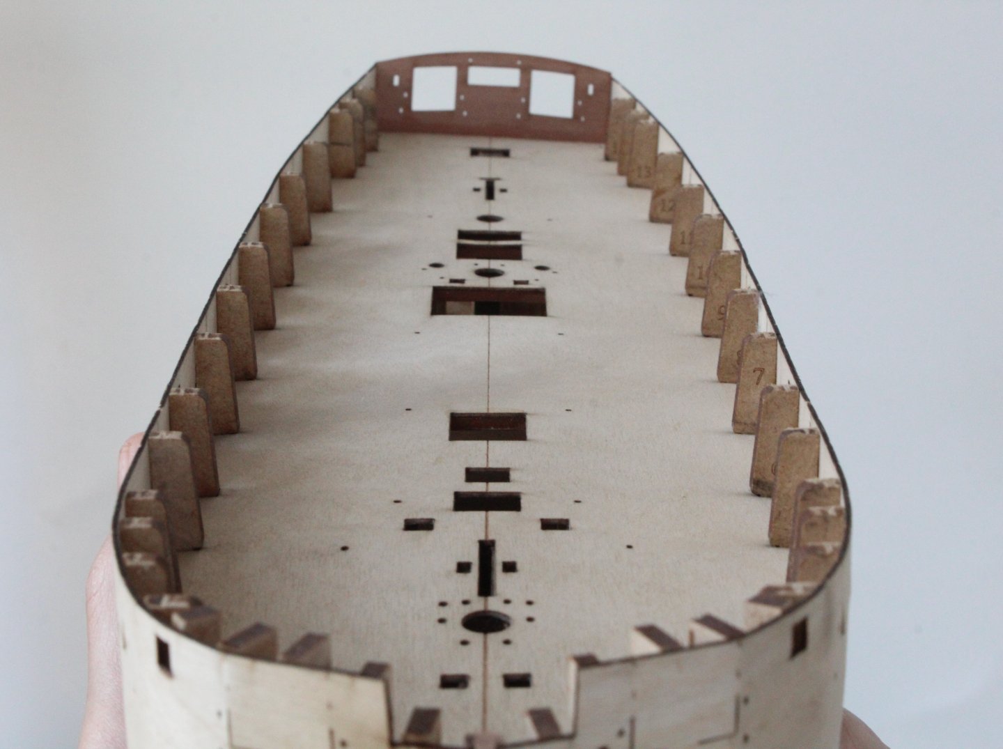
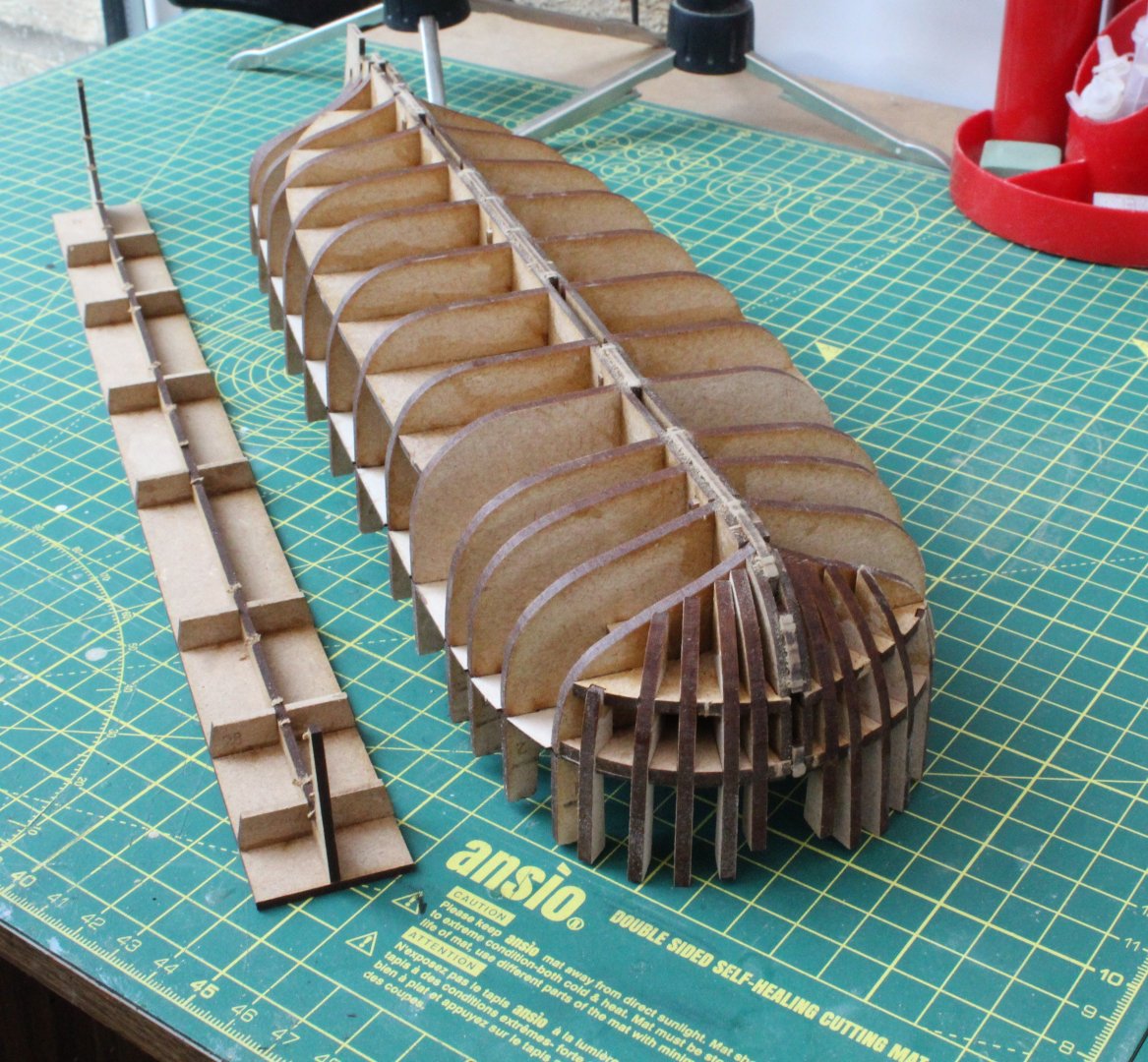
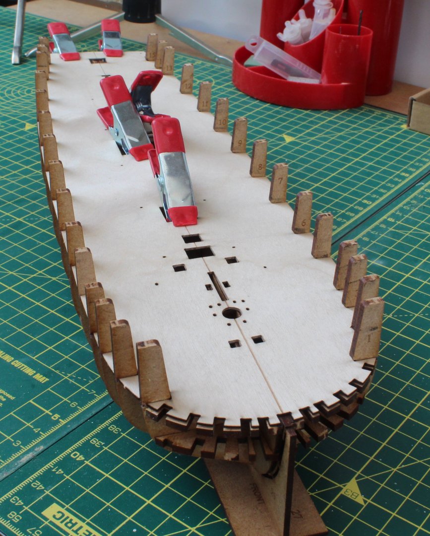
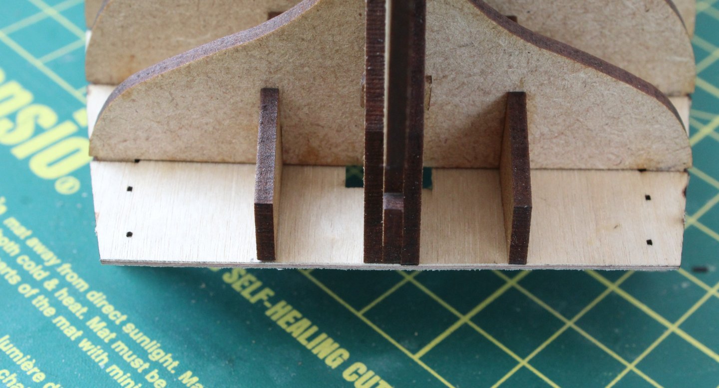
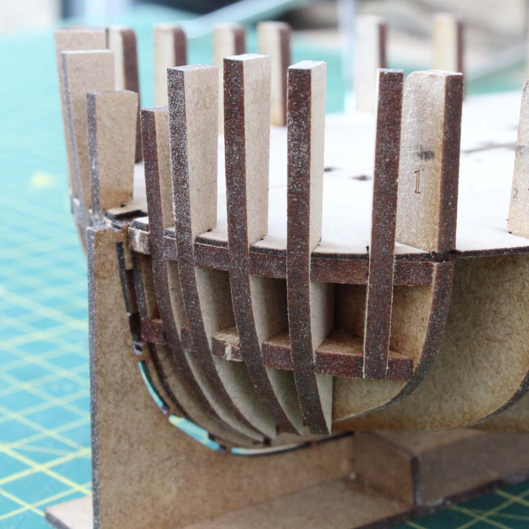
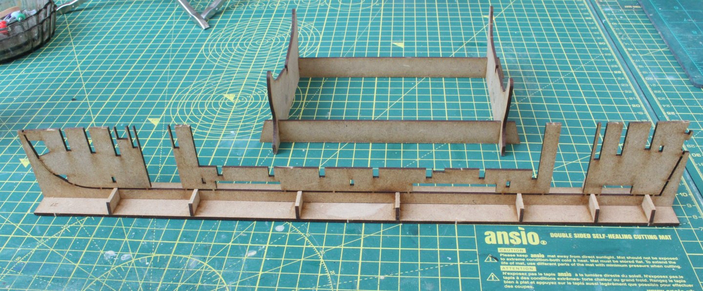
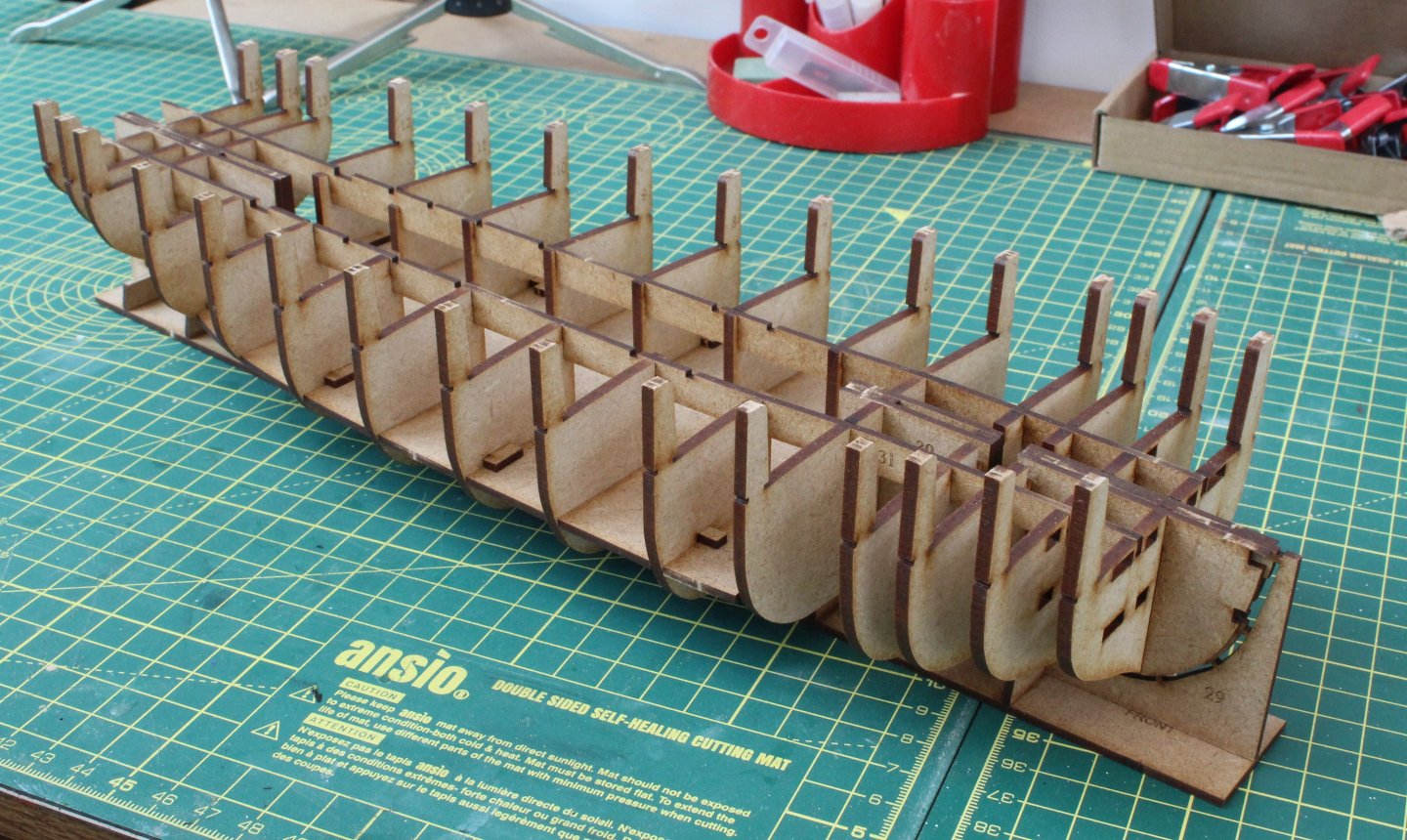
Build Log Index Hull Construction Part 1 Date: 11/07/2024 Time worked: 50 minutes After looking over all the plan sheets and then returning home from my afternoon run I had a little bit of spare time so I decided to make a start on the hull construction. So far everything has fitted together perfectly which comes as no great surprise. The first task was to glue 7 off inner keel supports into the inner keel jig base slots. Once that was done the main keel was carefully removed from the 2mm MDF sheet and deburred before it was added, but not glued, into the slots provided on the inner keel support jig. I also assembled the temporary cradle. The next task was to remove bulkheads 1 to 15 from the 3mm MDF sheet and to then slot them into their respective positions on the main keel. These are not glued at this stage of the build process. Before each bulkhead was pushed home I did debur the top edge. It is important to ensure / check they are all fully engaged in the main keel slots. The next parts fitted (but not glued) were the two keel doubler patterns which fit either side the main keel. As with the bulkheads it is important to ensure both these patterns are fully engaged. There are 5 locking pegs which are to ensure the keel doublers are correctly aligned with the main keel. These were pushed in place place without any problems. Wood glue was used to secure the locking key pegs as each one was inserted. Moving swiftly on the lower deck (part 32), which is incorrectly listed as part 12 in the build manual, was slotted in position on the hull frame. Once in place 8 off locking pegs were used to lock the lower deck in place, 4 pegs per side. The 2 off longitudinal supports were fitted next. These can be glued in place. There is a note on Dan’s build log from Chris regarding these supports which I have include below which reads as follows: Regarding the rear most bulkhead, I decided to remove the tab at the end of the longitudinal brace, as it would have been too difficult to slot into place. I should have deleted the holes in the pear stern, but forgot – but they are not at all important to the overall assembly, just surplus. The hull is now starting to take shape. The Brig Adder is quite small when compared with the Indy. According to the build manual the next part to be fitted is the stern transom bulkhead. When reading through Dan’s Adder build log he fitted the sub deck before stern transom bulkhead and then noted there was a small overhang of the sub deck which needed trimming. This is quite normal as Chris noted that he does usually make these type of parts over long to cover all eventualities, better to have too much than too little. I will check the sub deck fitting before I decide if I need to trim it before it is fitted.


-
Enjoy the ride
-
You're righ😀t. I like to keep myself busy and it is a hobby I enjoy.
-
Hello Andrew. I am looking forward to this build
-
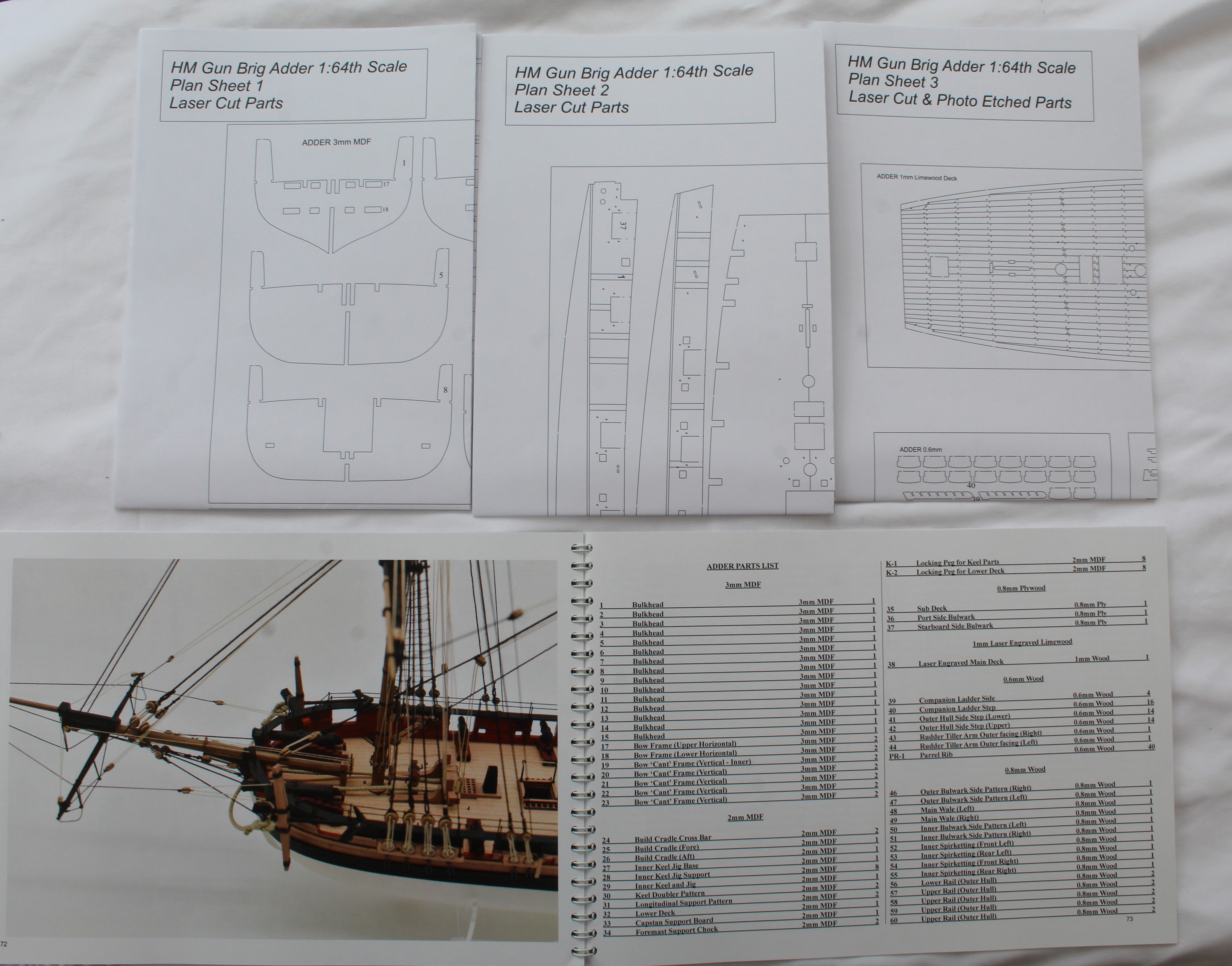
Introduction The HM Brig Adder was an Acute Class, brig-rigged warship that enjoyed popularity in the Royal Navy during the Napoleonic Wars. The HM Brig Adder was armed with 12 x 18 pounder carronades on the broadside, with 2 x 24pdr long guns in the bow. The Acute Class boats were manned by a crew of 50 men and boys. Not being ocean-going vessels, they were commanded by a Lieutenant-in-Command rather someone appointed to be their Master and Commander and he was the only commissioned officer aboard. The Acute Class were designed to operate under oars when in shallow, inshore waters and for that reason, they were shallow-draughted and flat-bottomed. They were also fitted with an innovative invention, the Schank Sliding Keel so that they could operate under sail. The estimated build time, in the build manual, is between 40 to 60 hours. It will probably take me considerably longer to complete. I am normally able to spend between 2 to 4 hours most days in the shipyard but I plan to go slow and steady with this build. I will try to keep a log of the hours spent of this project as part of this build log. The Kit Scale: 1:64 Length Overall: 615mm Height Overall: 493mm Width Overall: 208mm The kit includes: a) Laser cut and engraved parts in MDF and pear wood. b) Laser etched and cut lime wood deck with treenail detail. c) 3 sheets of photo etched brass. d) High resolution 3D-printed parts. e) Double planked hull in limewood for first planking and pear wood for second planking. f) Walnut dowel for masting. g) Multiple sizes of both black and natural rigging thread along with all necessary blocks and deadeyes. h) Comprehensive, full colour instruction manual, along with 12 plan sheets which include all masting and rigging drawings. i) Features include laser-engraved treenails on both inner and outer bulwarks. Build Plan My plan, with this build log, will be to show photos of my progress together with some examples of the processes / methods used when undertaking some of the tasks. I have initially broken the build down to a series of major tasks and have created a build log index. Build Log Index Build Manual and Plan Sheets The manual, as with all Vanguard Model kits, is very comprehensive and informative. It is contains hundreds of high quality colour photos which complement the very detailed build instructions. I also like the fact that you can download a pdf copy of the build manual from Vanguard Model's web site which means you are able to study and understand the build before deciding to purchase the kit. Also I find it is very useful to keep a copy on my laptop so I can zoom in on some of the build manual photos. The build manual also contains a detailed parts list to assist the builder locate the various parts which can be used in conjunction with the information shown on plan sheets 1, 2 and 3. Plan sheets 4, 5 and 6 provide very useful supplementary hull assembly information. Plan sheet 4 will be used for the initial hull construction. Plan sheet 5 shows the detail for the deck items and bulwarks. It also contains information regarding building and painting the various deck items, such as the hand pumps, ship's wheel, etc. Plan sheet 6 essentially will be used when adding the external hull details, such as the channels, deadeyes, chain plates / links, ship steps, rudder, etc. It also shows the drop keel assembly detail, if you decide to include it as part of your build. Detailed manufacturing instructions for the masts, bowsprit and yards, main boom and main gaff are provided on plan sheets 7 and 8. Compressive rigging information is provide on plan sheets 9, 10, 11 and 12. The shrouds, ratlines and back stays are shown on plan sheet 9 along with the futtock staves, catharpins and bowsprit gammoning. The mast stays and main boom and main gaff running rigging is shown on plan sheet 10. Plan sheet 11 shows the yard jeers and tyes rigging and all the yard brace rigging is shown on plan sheet 12. I will spend the rest of today looking over the plan sheets and making copious notes which will help me once I start the build process. I plan to make a start on the Brig Adder construction this coming weekend as tomorrow my wife and I look after one of our younger grandkids during the day and then our two eldest grandkids come for tea, after school.