HOLIDAY DONATION DRIVE - SUPPORT MSW - DO YOUR PART TO KEEP THIS GREAT FORUM GOING! (Only 20 donations so far - C'mon guys!)
×


Glenn-UK
-
Posts
3,154 -
Joined
-
Last visited
Content Type
Profiles
Forums
Gallery
Events
Everything posted by Glenn-UK
-
 Thanks Dan. I will using your Adder log as a point of reference when I start the Adder
- 587 replies
-
- 1
-

-
- Indefatigable
- Vanguard Models
- (and 1 more)
-
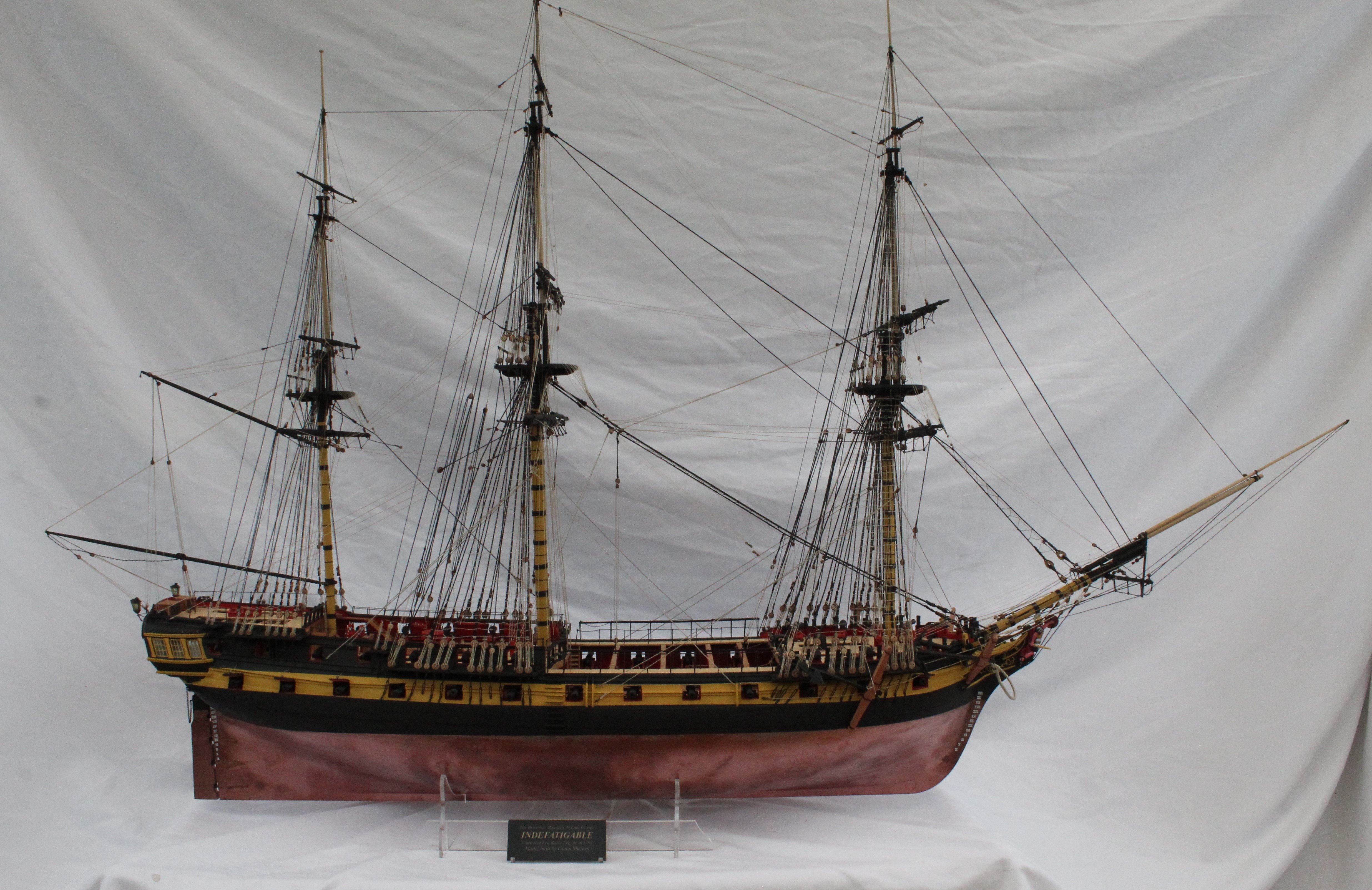
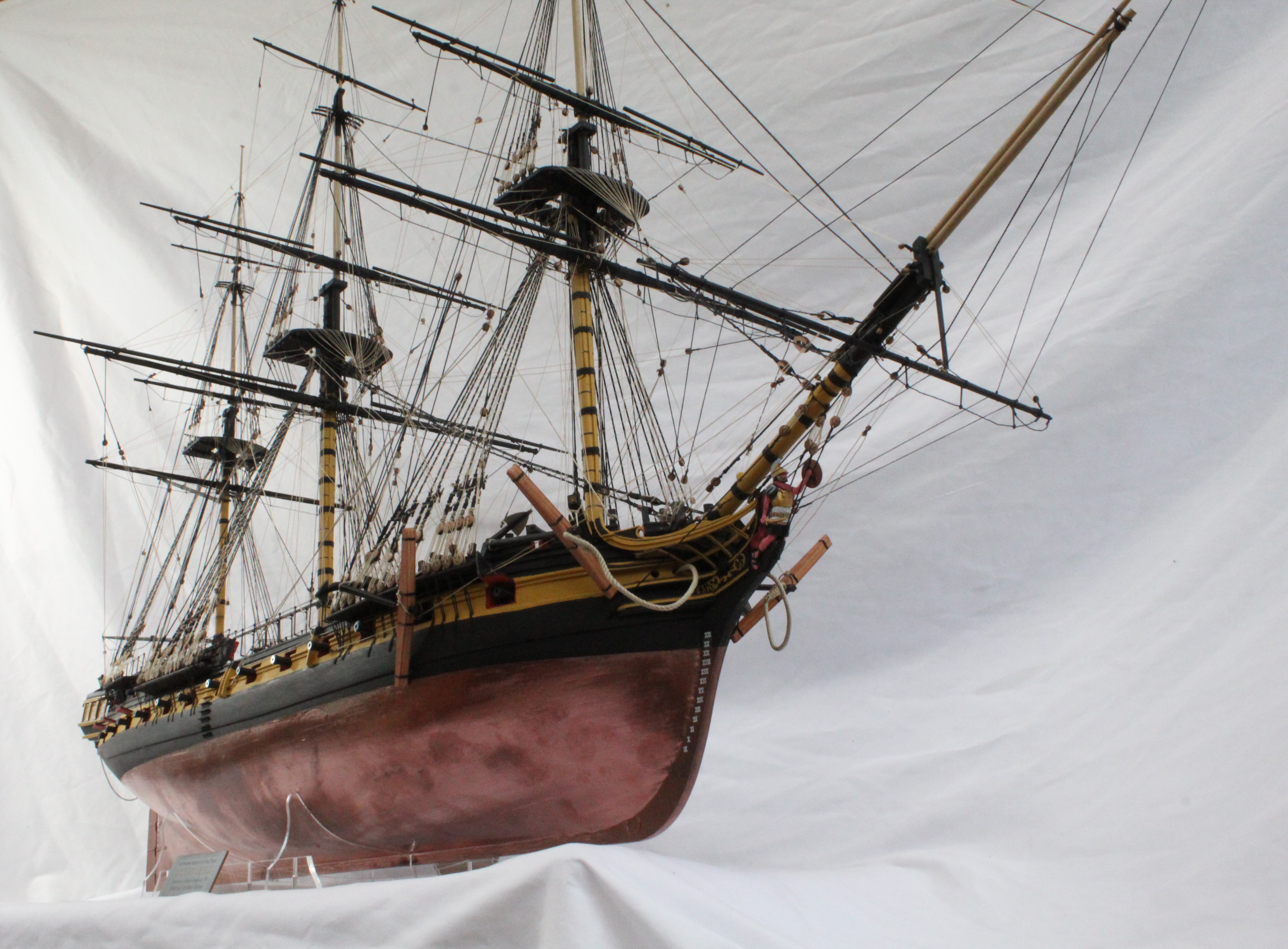
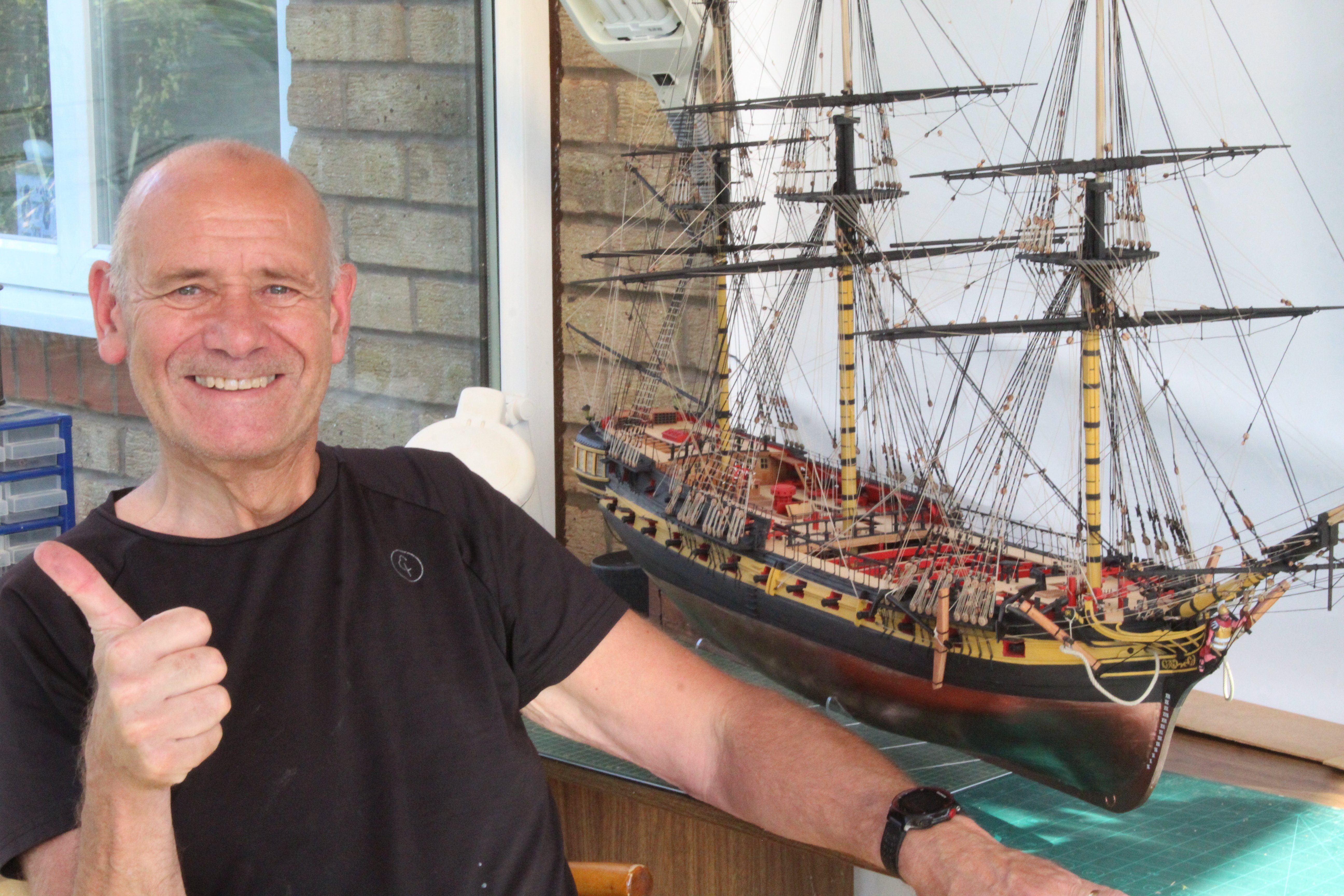
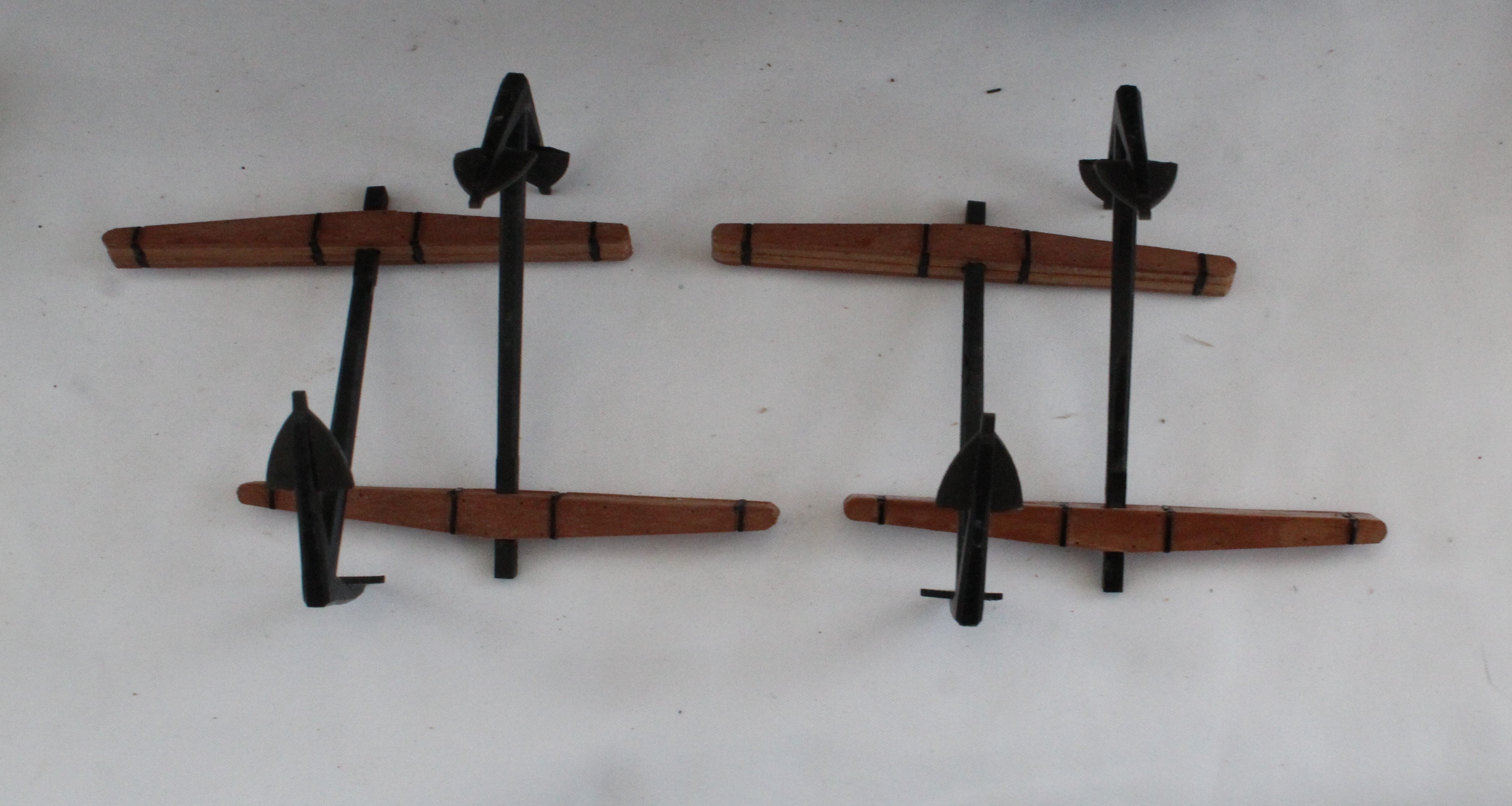
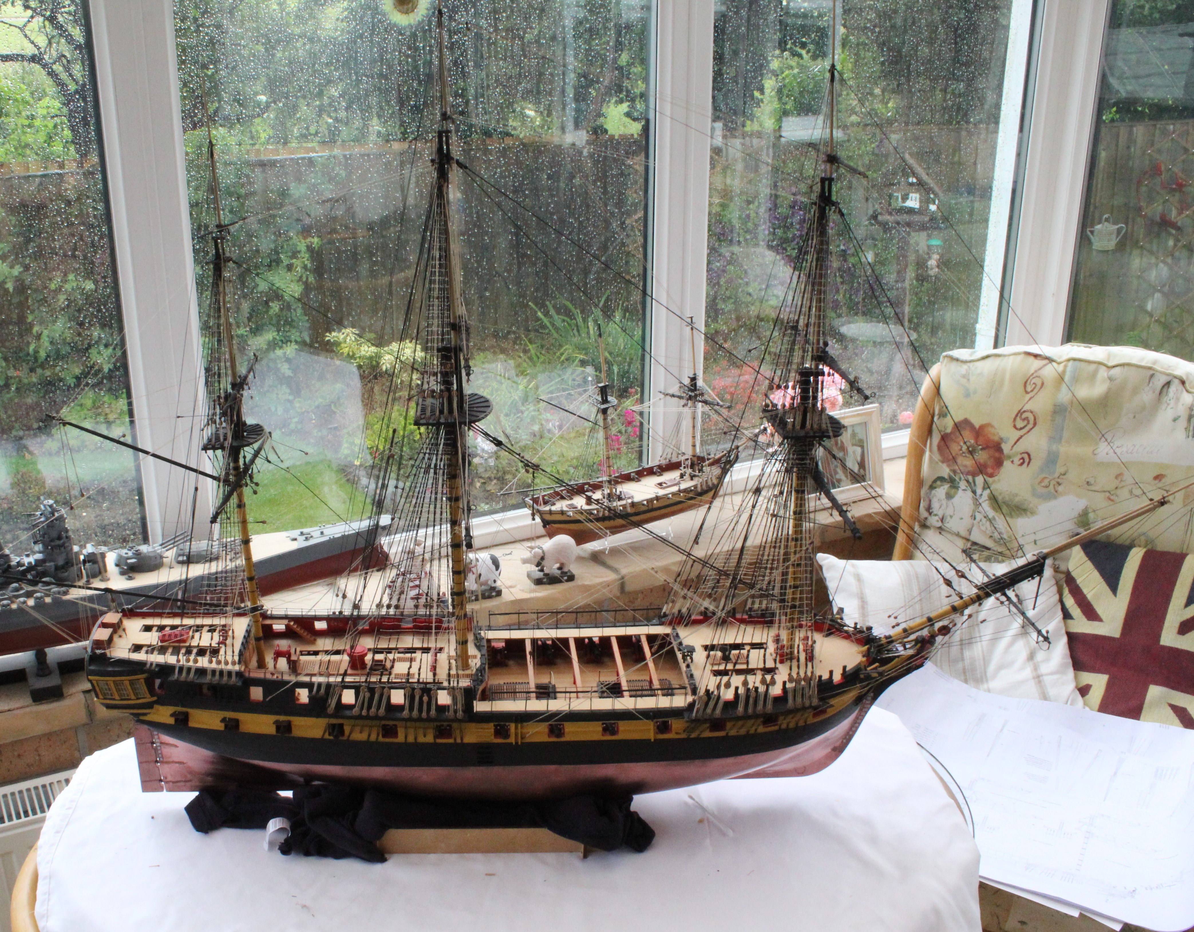
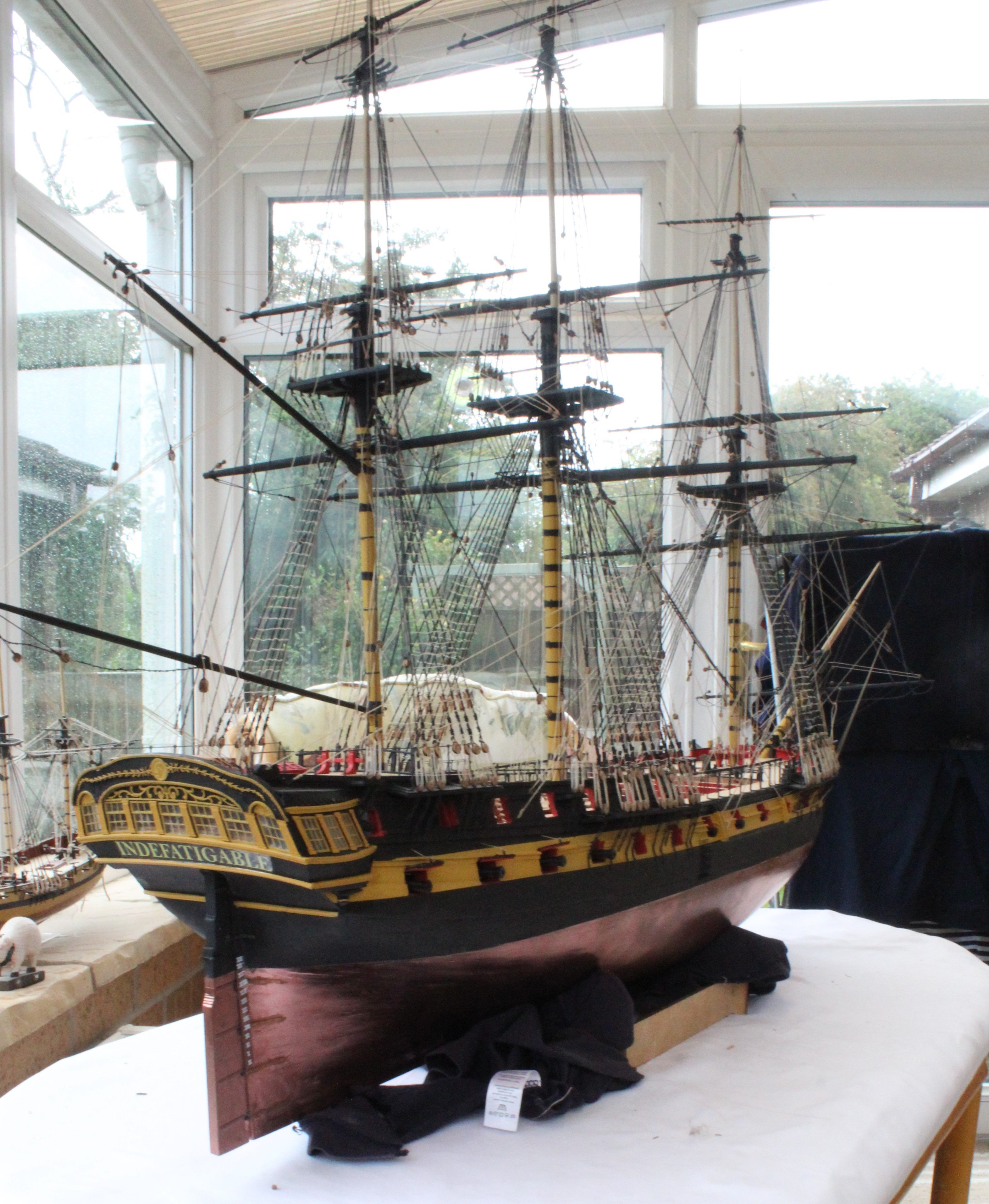
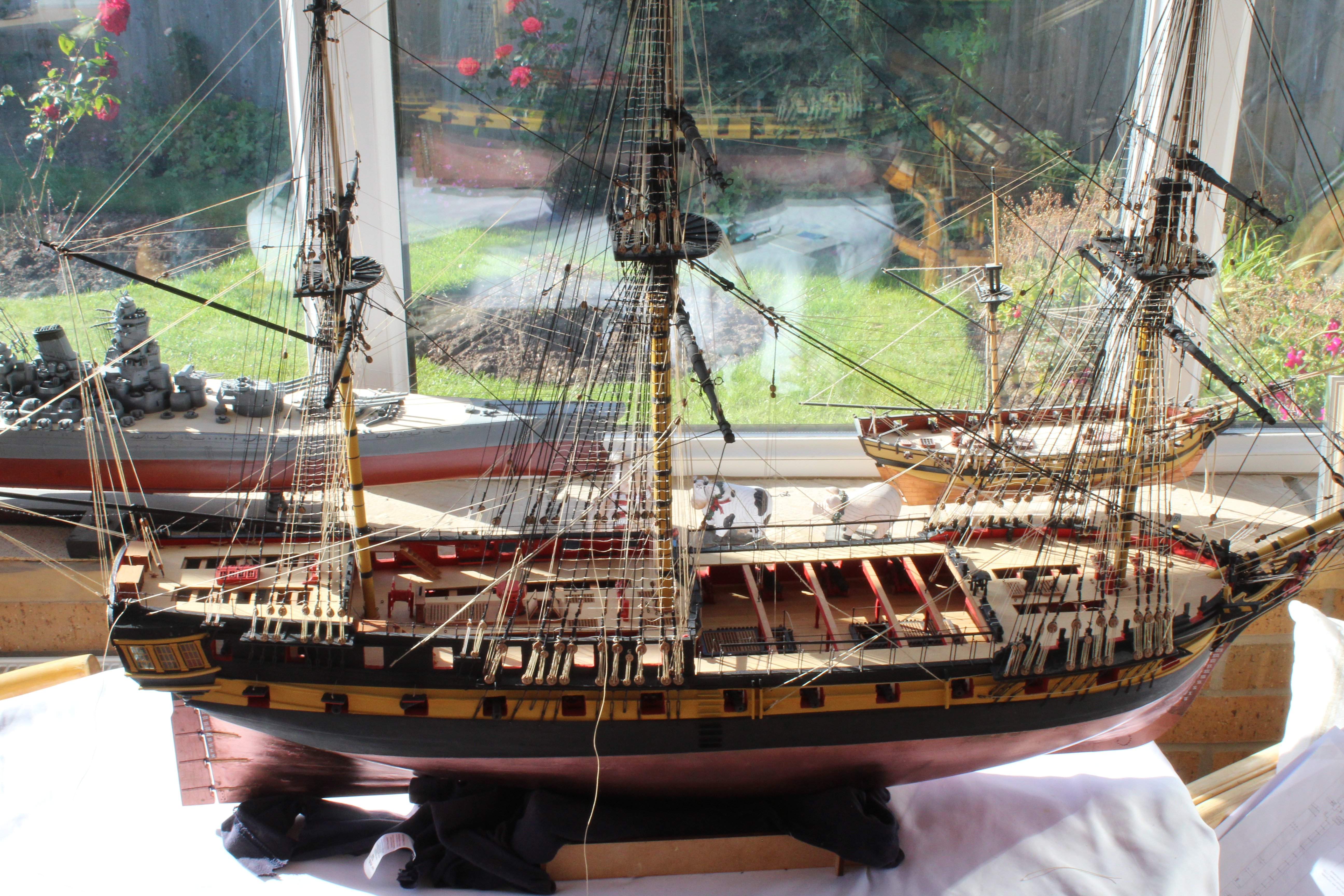
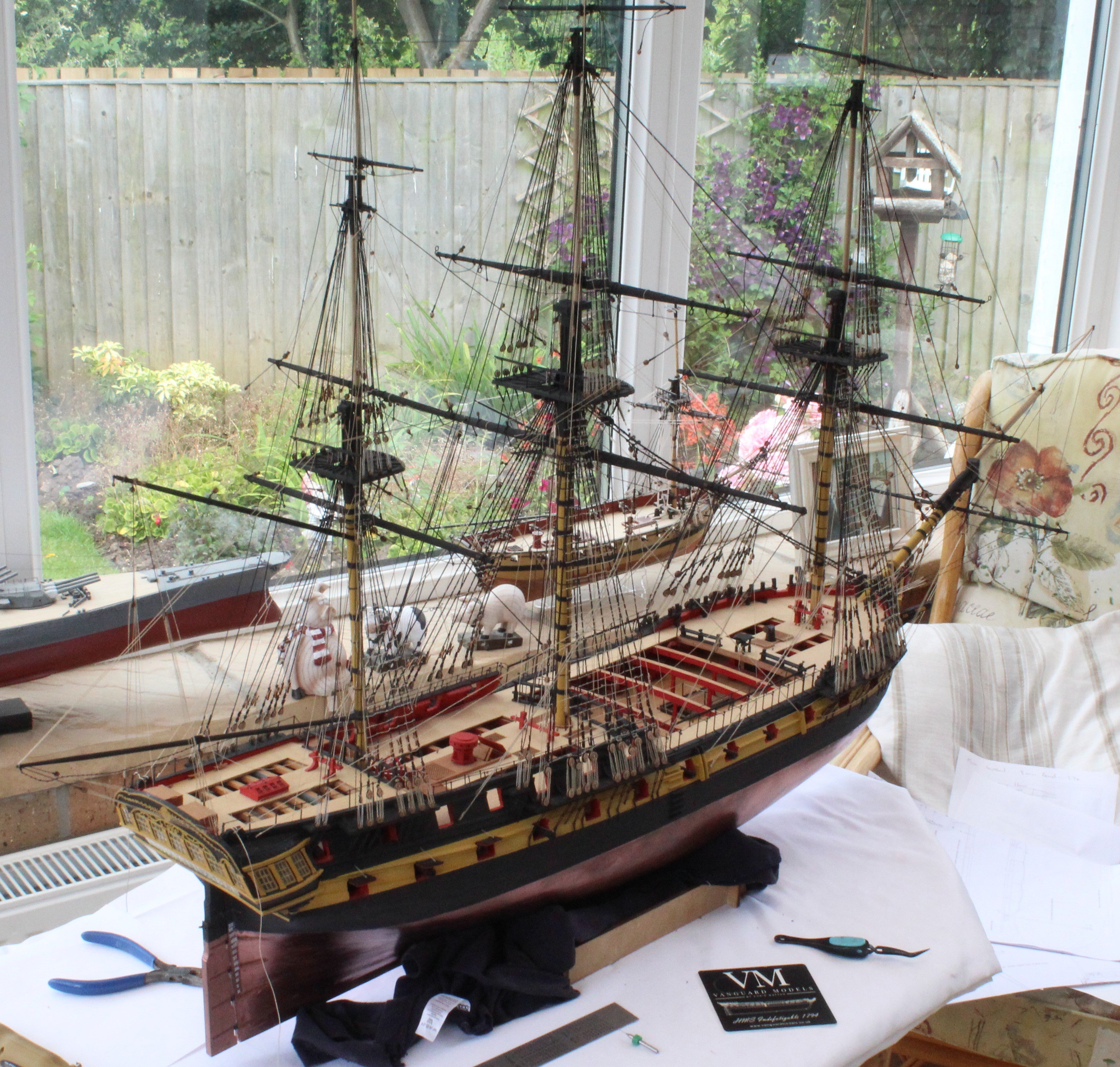
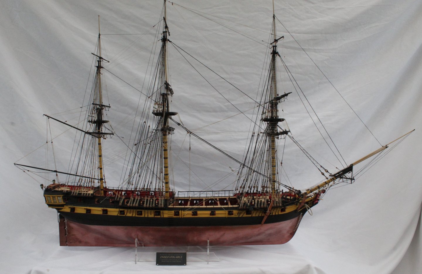
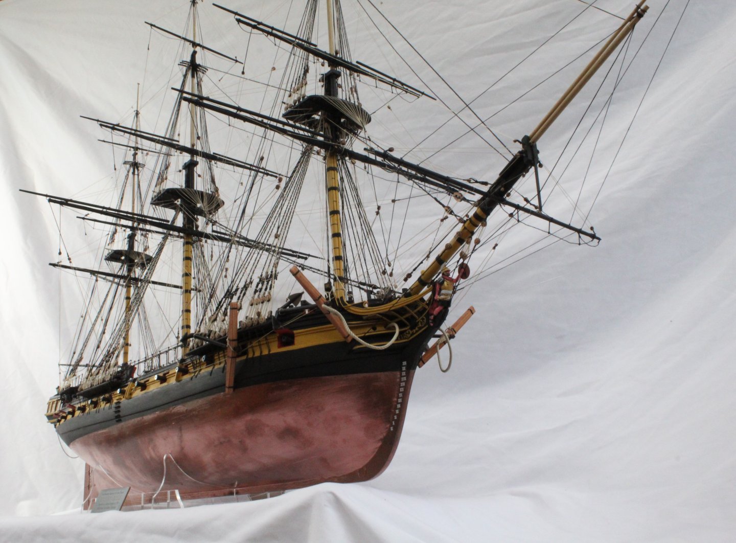
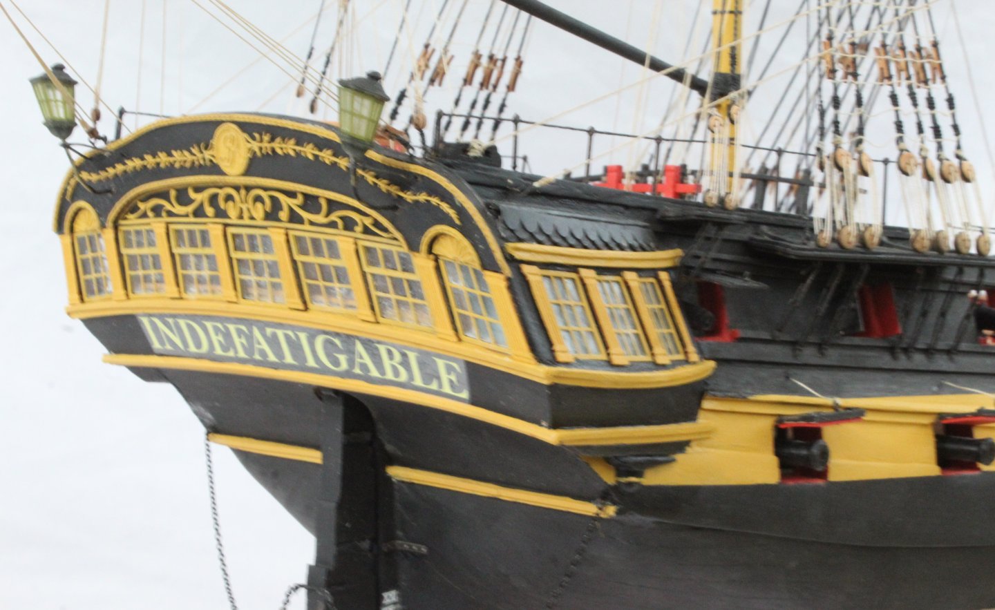
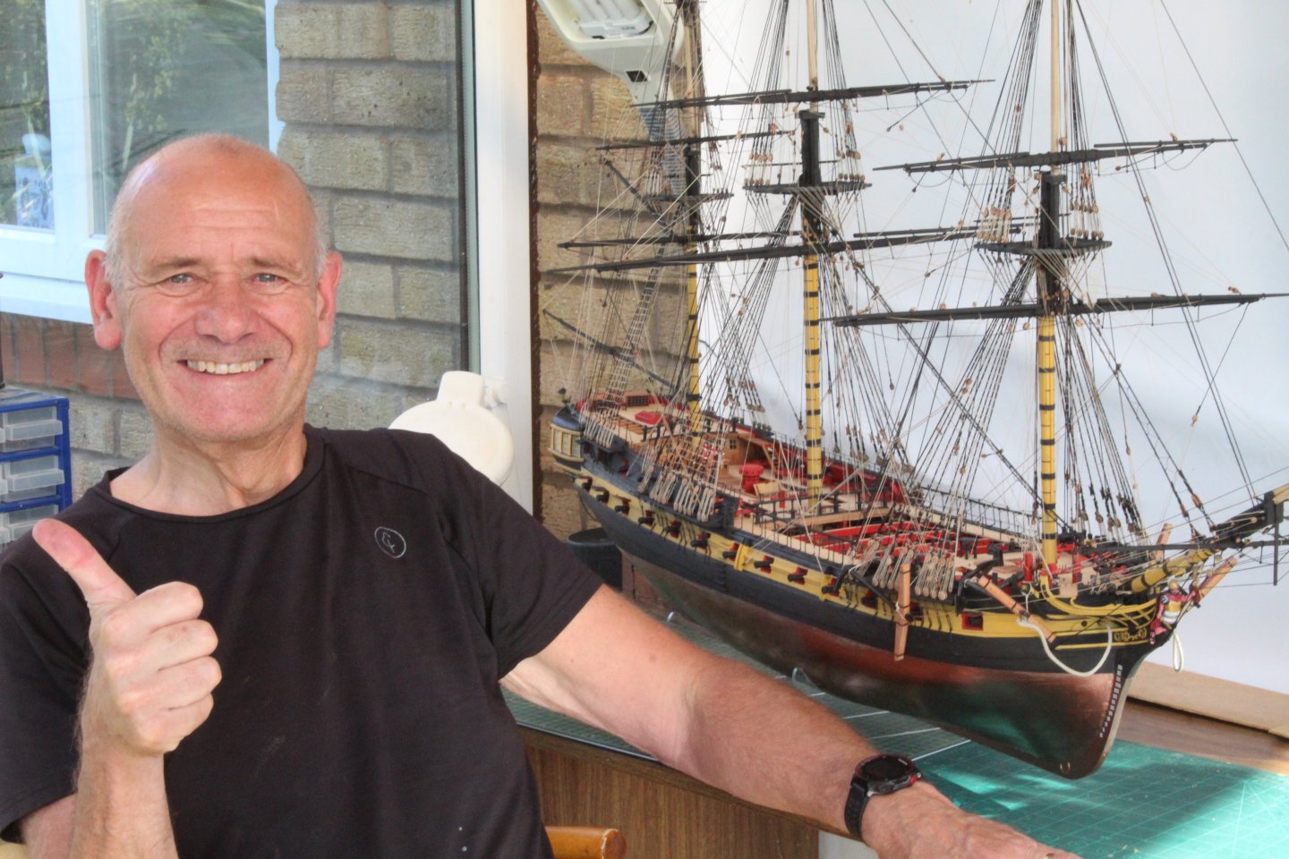
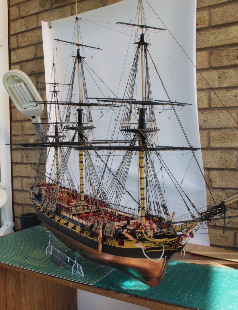
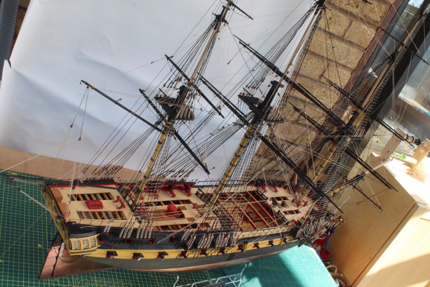
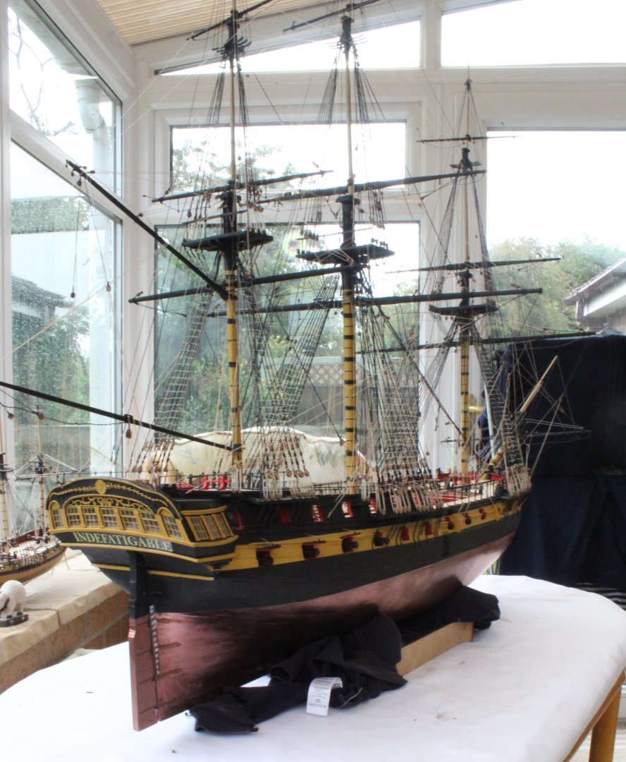
Many thanks to everyone who has followed, commented and liked my posts for this build log. I have really enjoyed building the Indy. It is an awesome kit. My next project will be the HM Brig Adder which I am really looking forward to start building once the kit arrives, hopefully later this week! I have taken a selection of some good photo's and some not so good photo's of my completed model.


- 587 replies
-
- 19
-

-
-

-
- Indefatigable
- Vanguard Models
- (and 1 more)
-
Many thanks
-
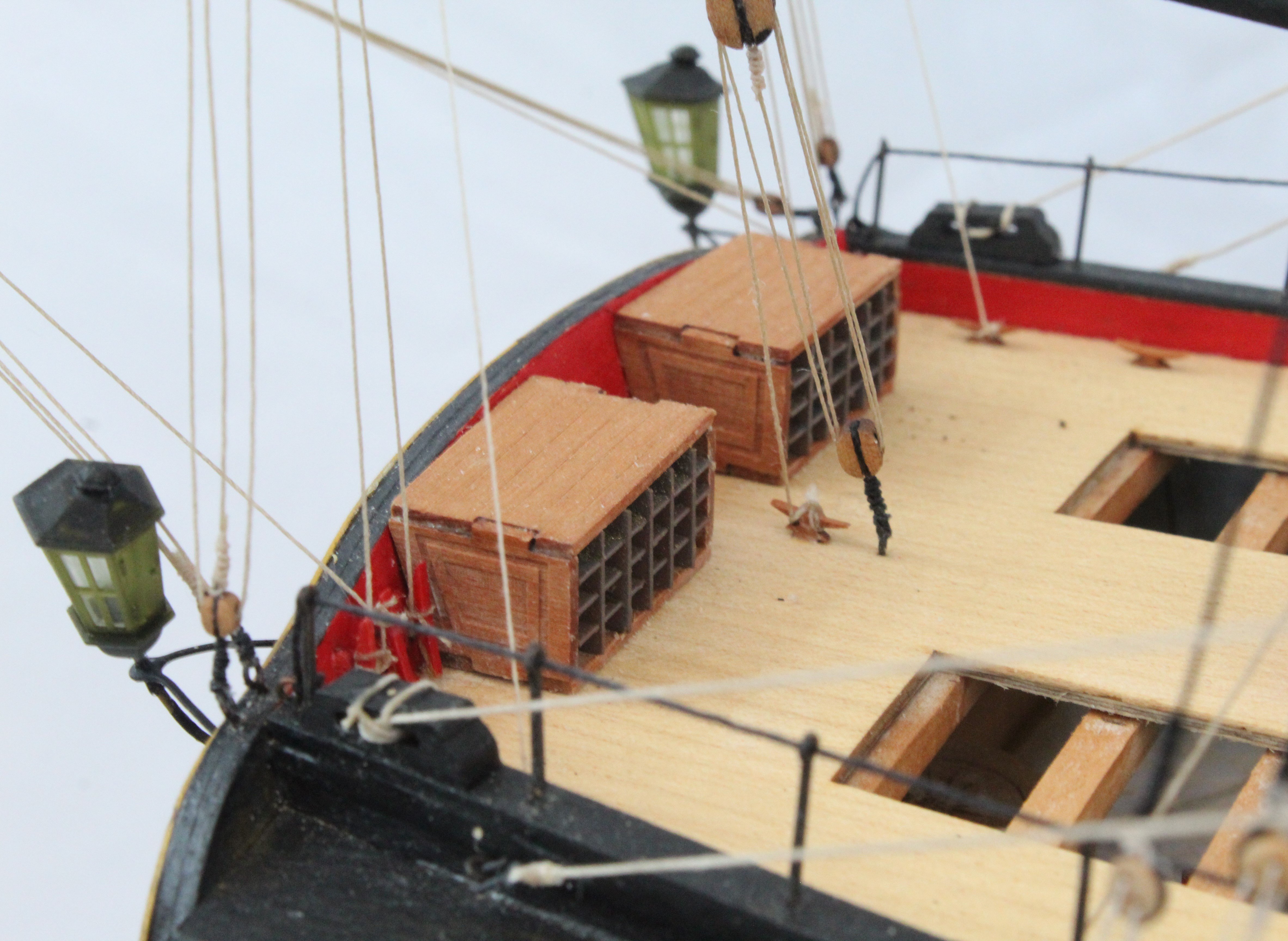
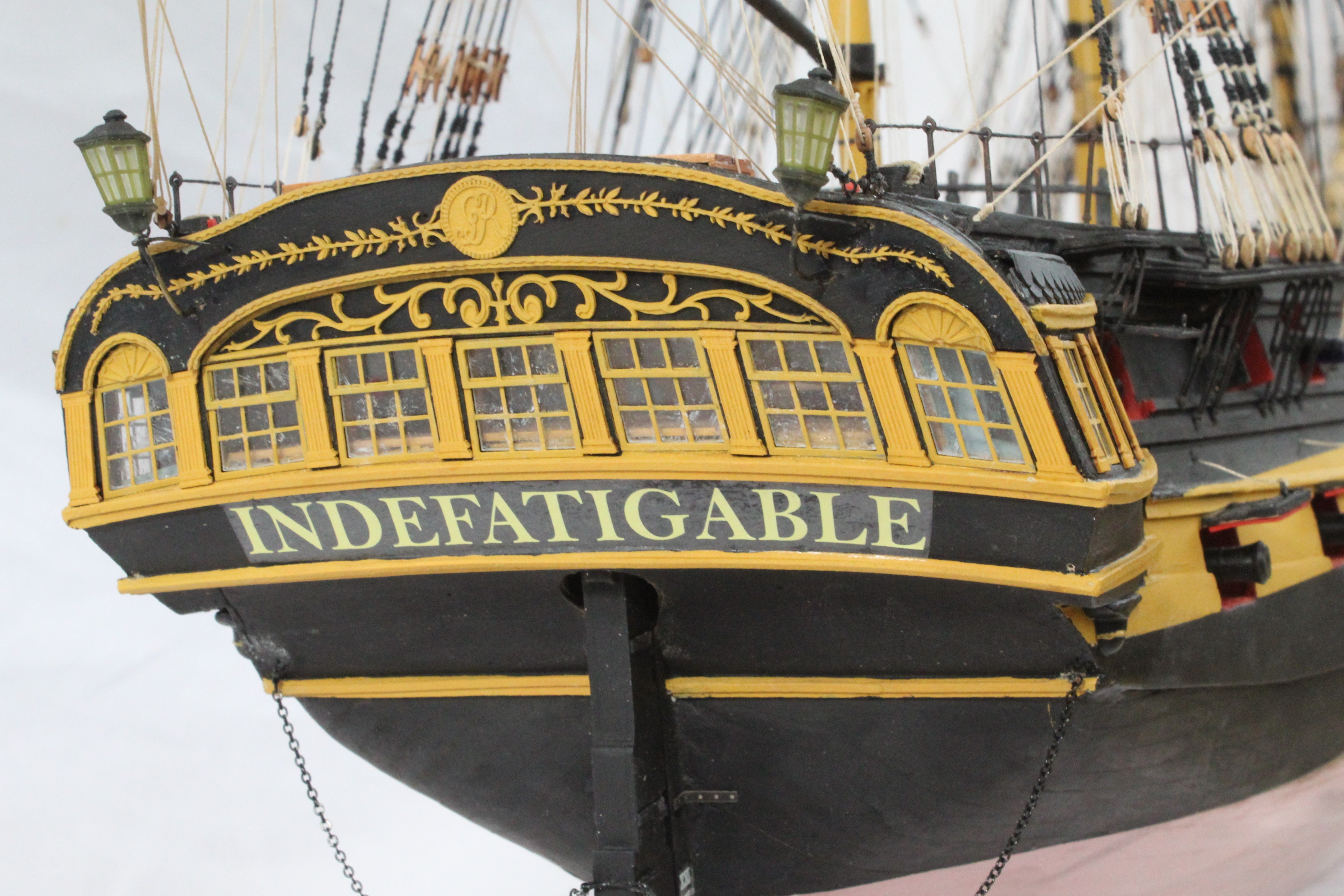
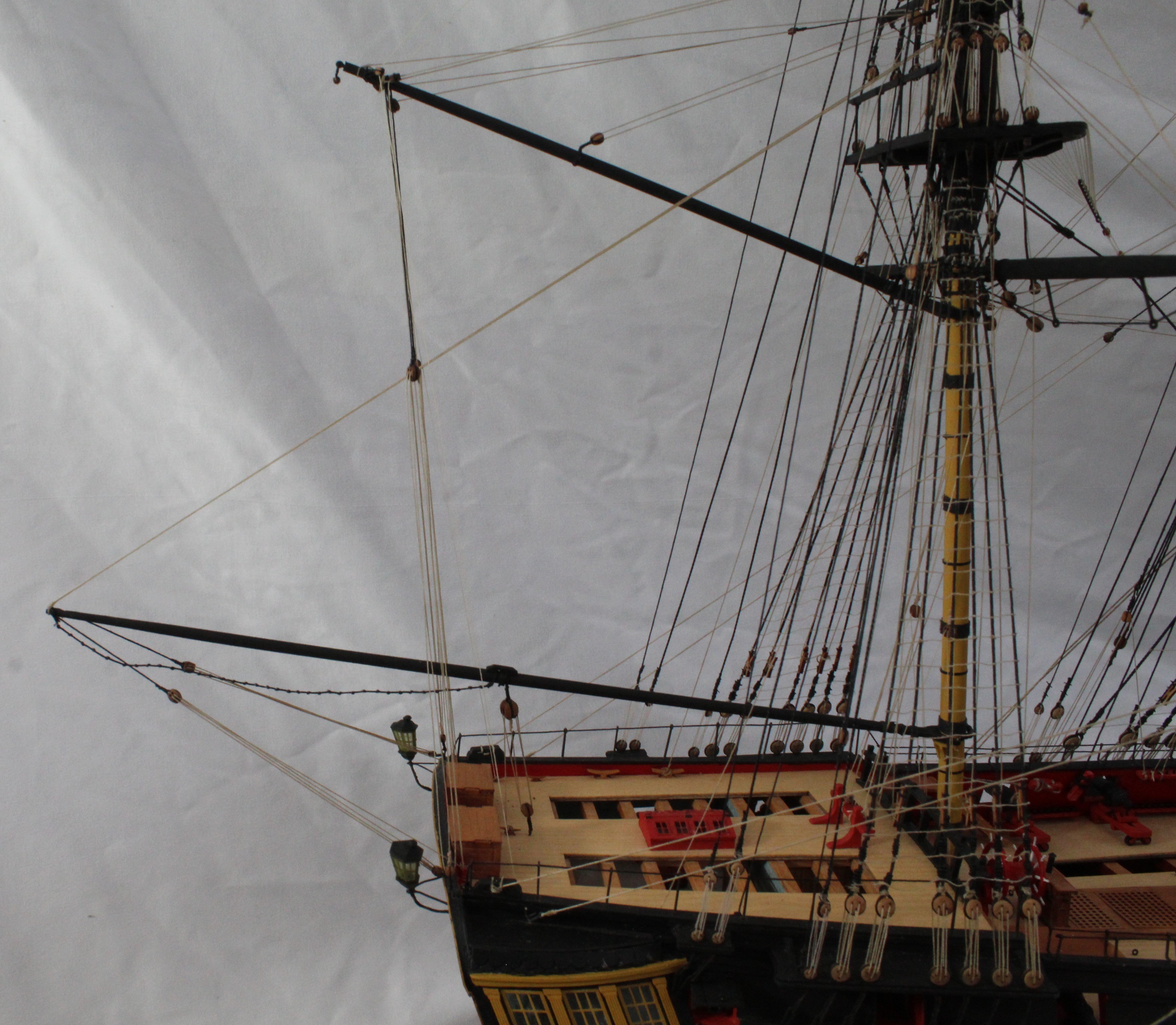
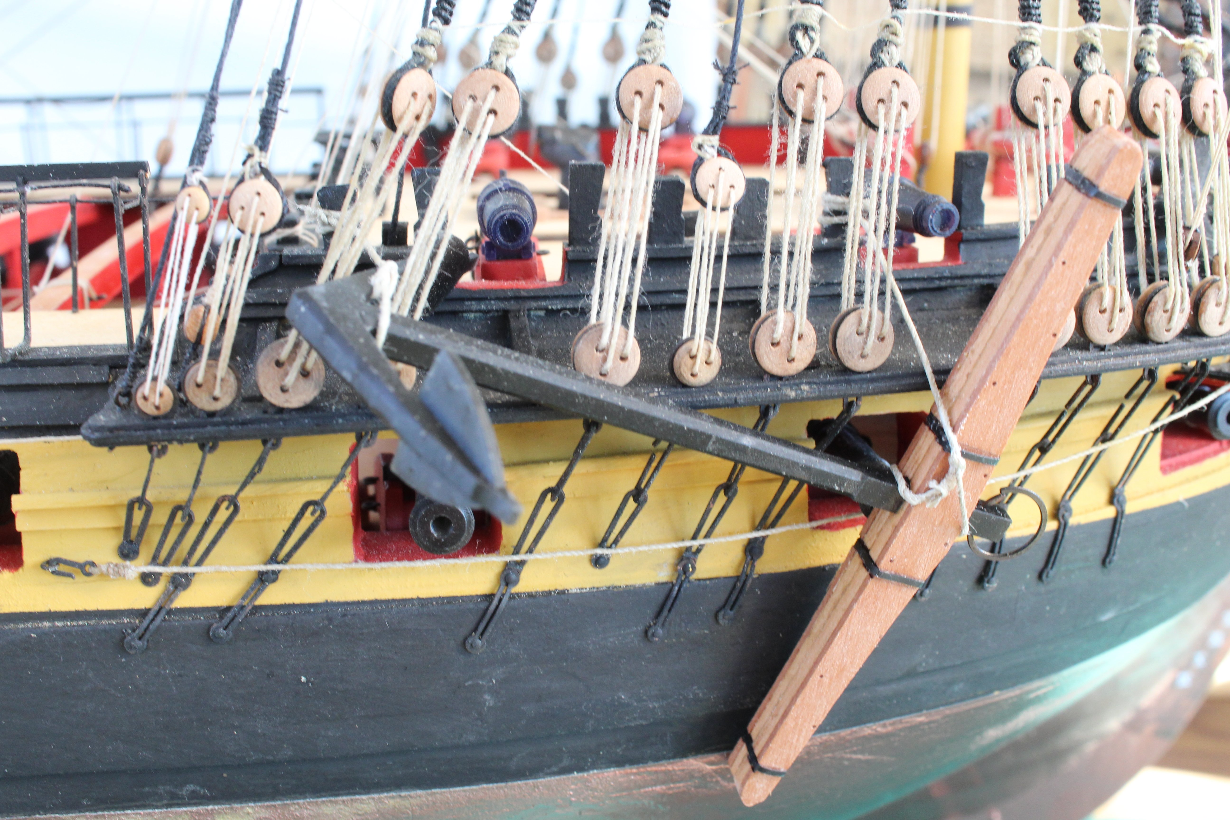
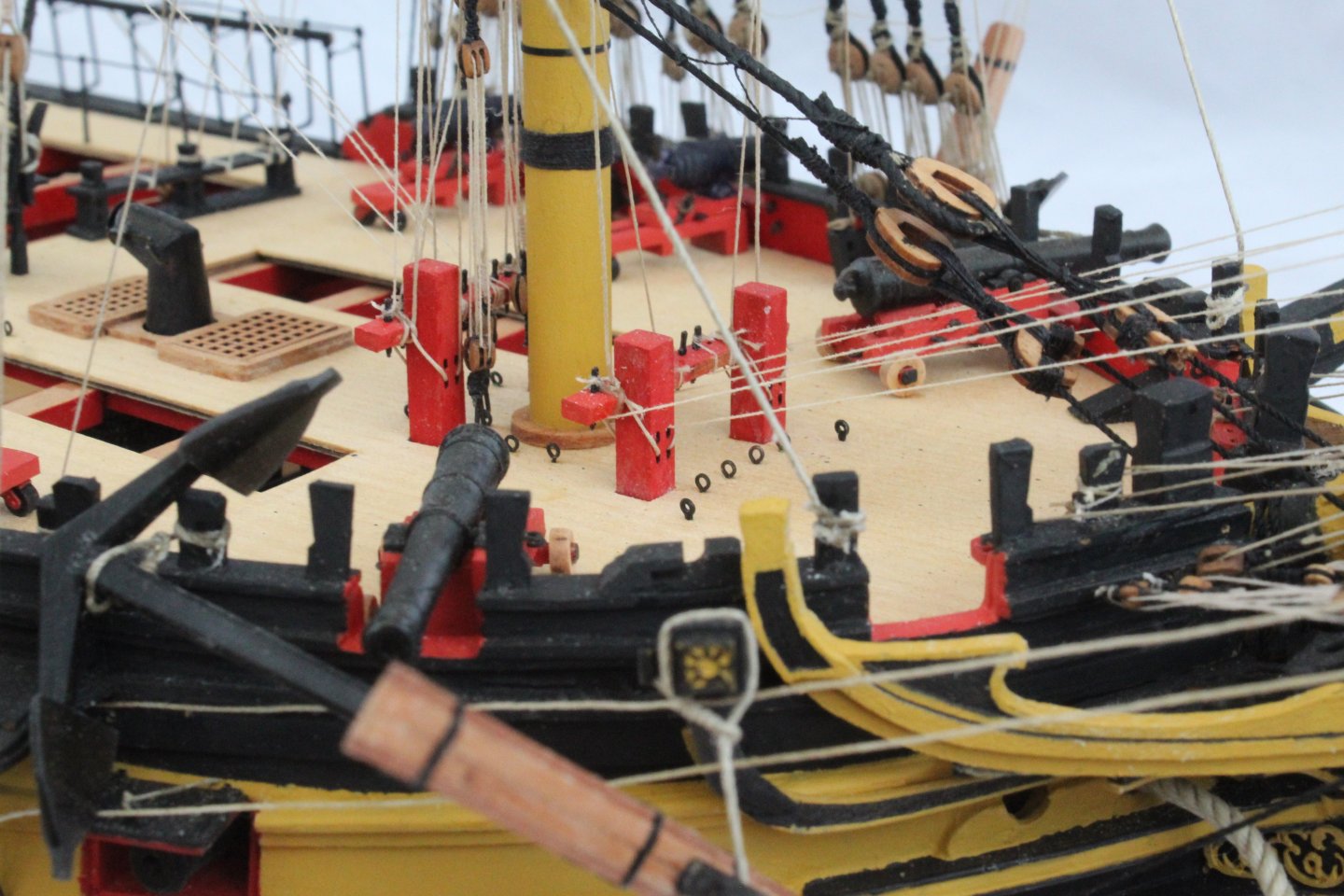
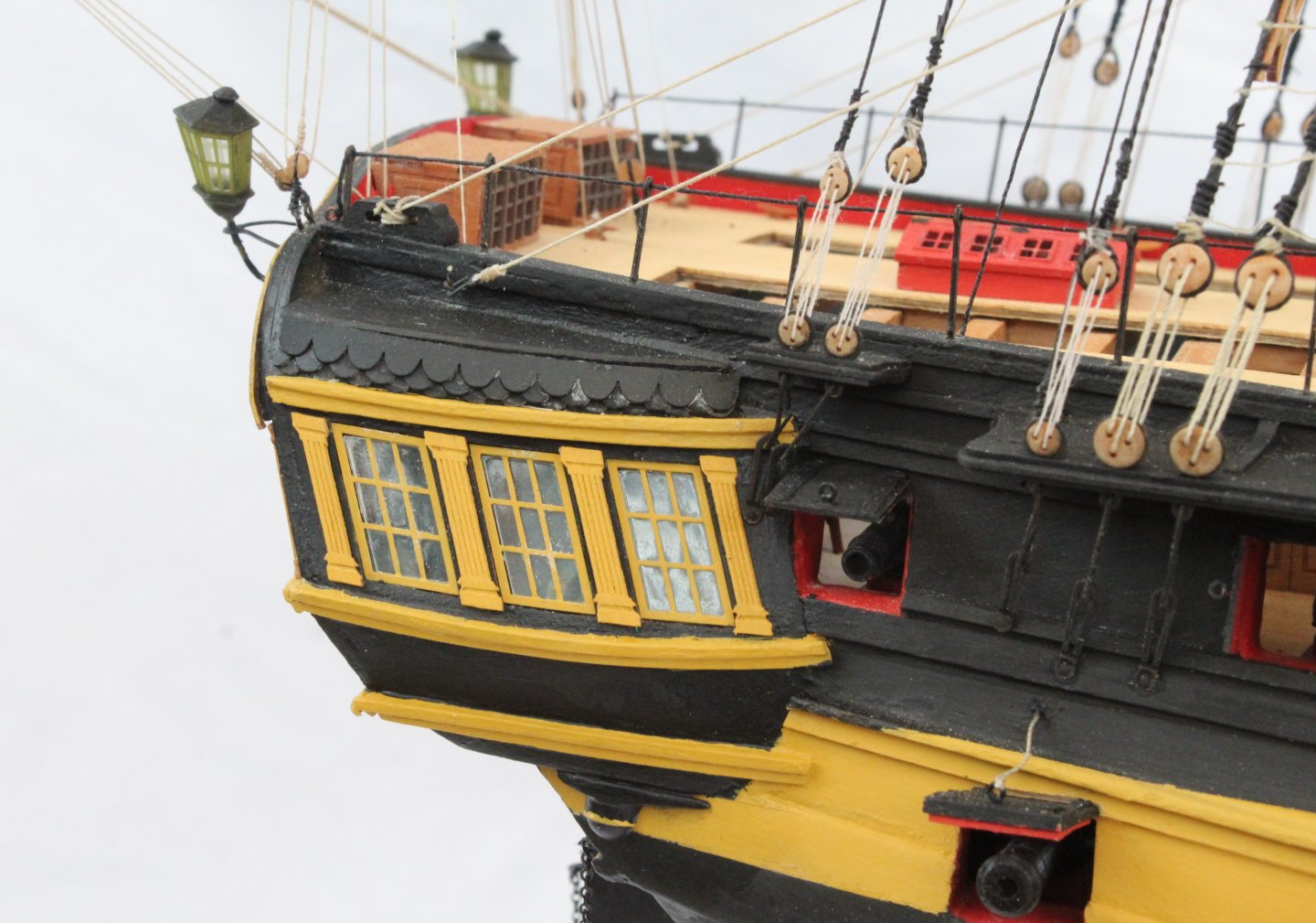
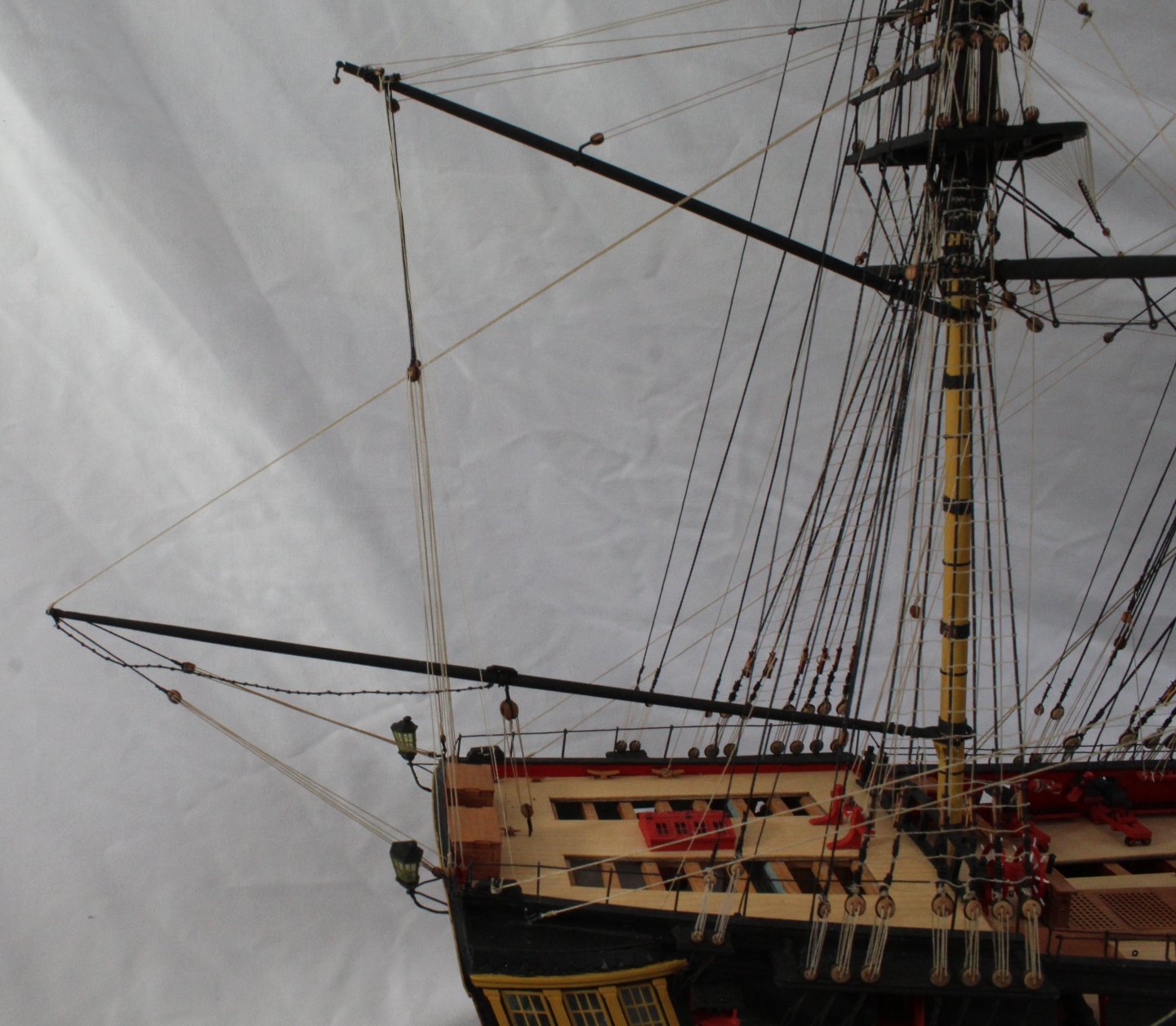
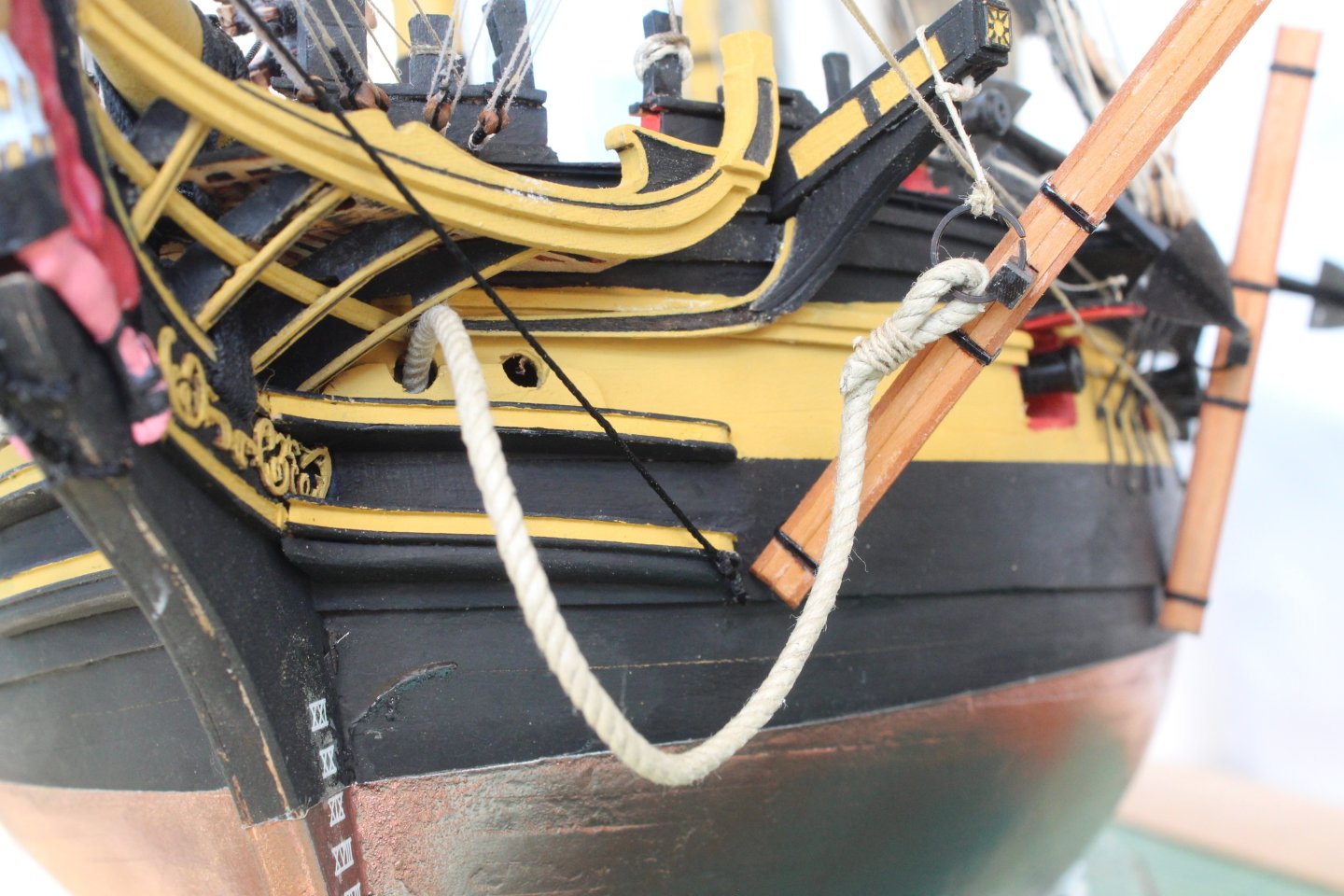
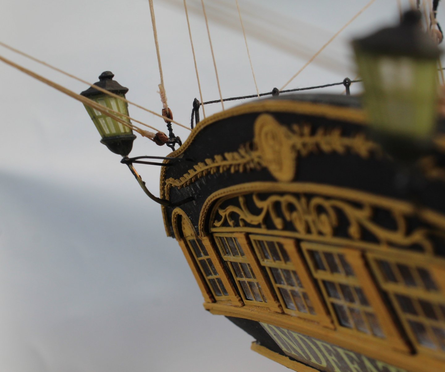
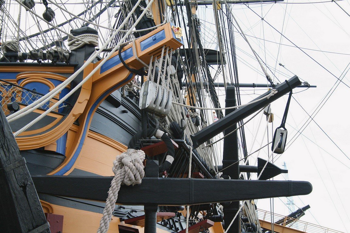
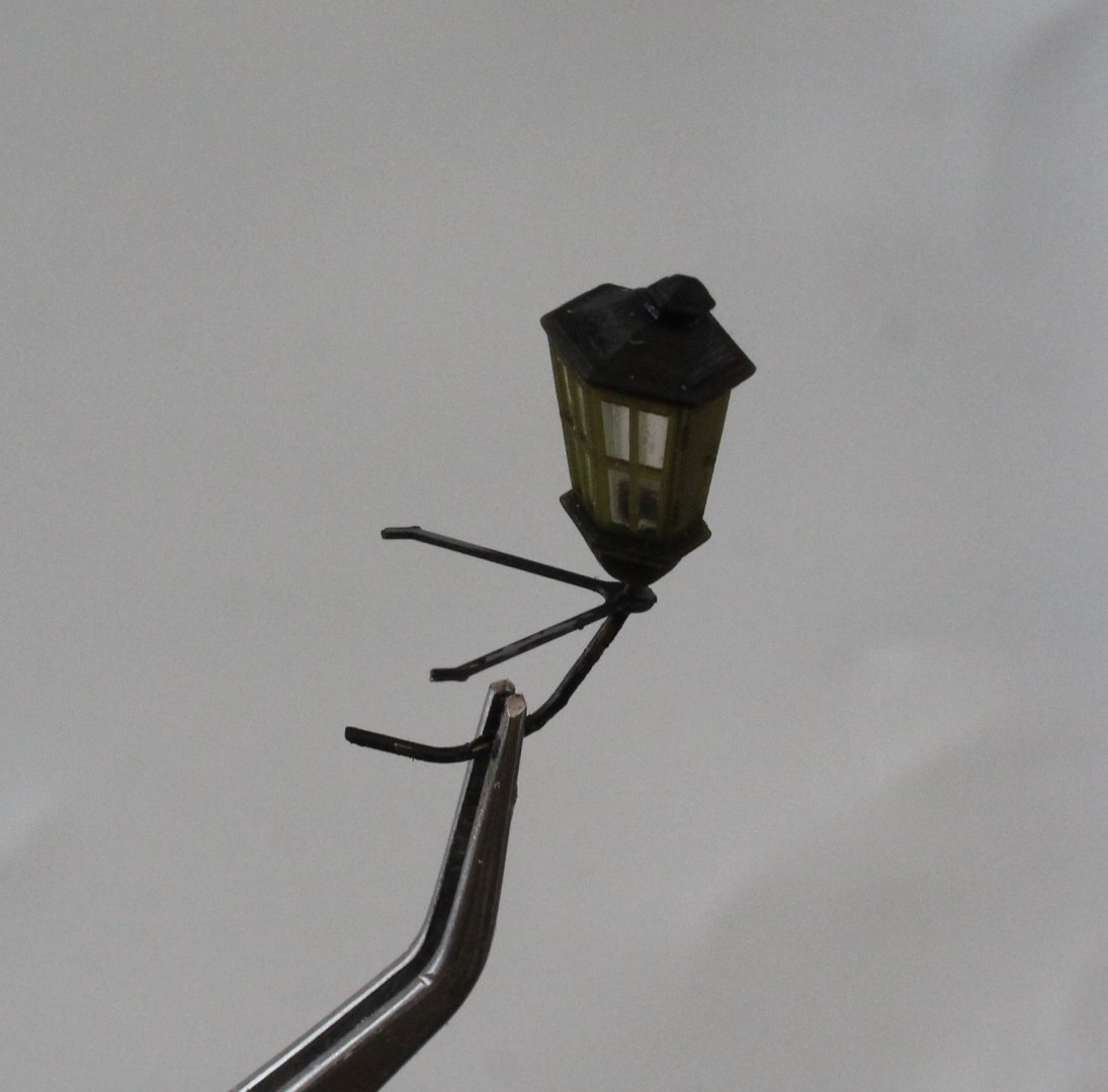
Anchors and Lanterns Today I installed the 4 off anchors and 2 off lanterns to the Indy. With regards to the main anchor I did toy with the idea of rigging a block through the davit, as shown in the following example. As I could not seem to pass the rigging thread through the holes in the davit I ended up rejecting this idea. I am reasonably happy with how the anchors look. Next the two lanterns were installed, a bit of touch up of the painting is required. I have now completed this wonderful kit. I will be taking a full set of completed photo tomorrow morning using my white backdrop as there are too many shadows from the sun to take them this evening. I did take a couple however for this post. and will be taking a full set of the completed Indy tomorrow. In th


- 587 replies
-
- 21
-
-
-
- Indefatigable
- Vanguard Models
- (and 1 more)
-
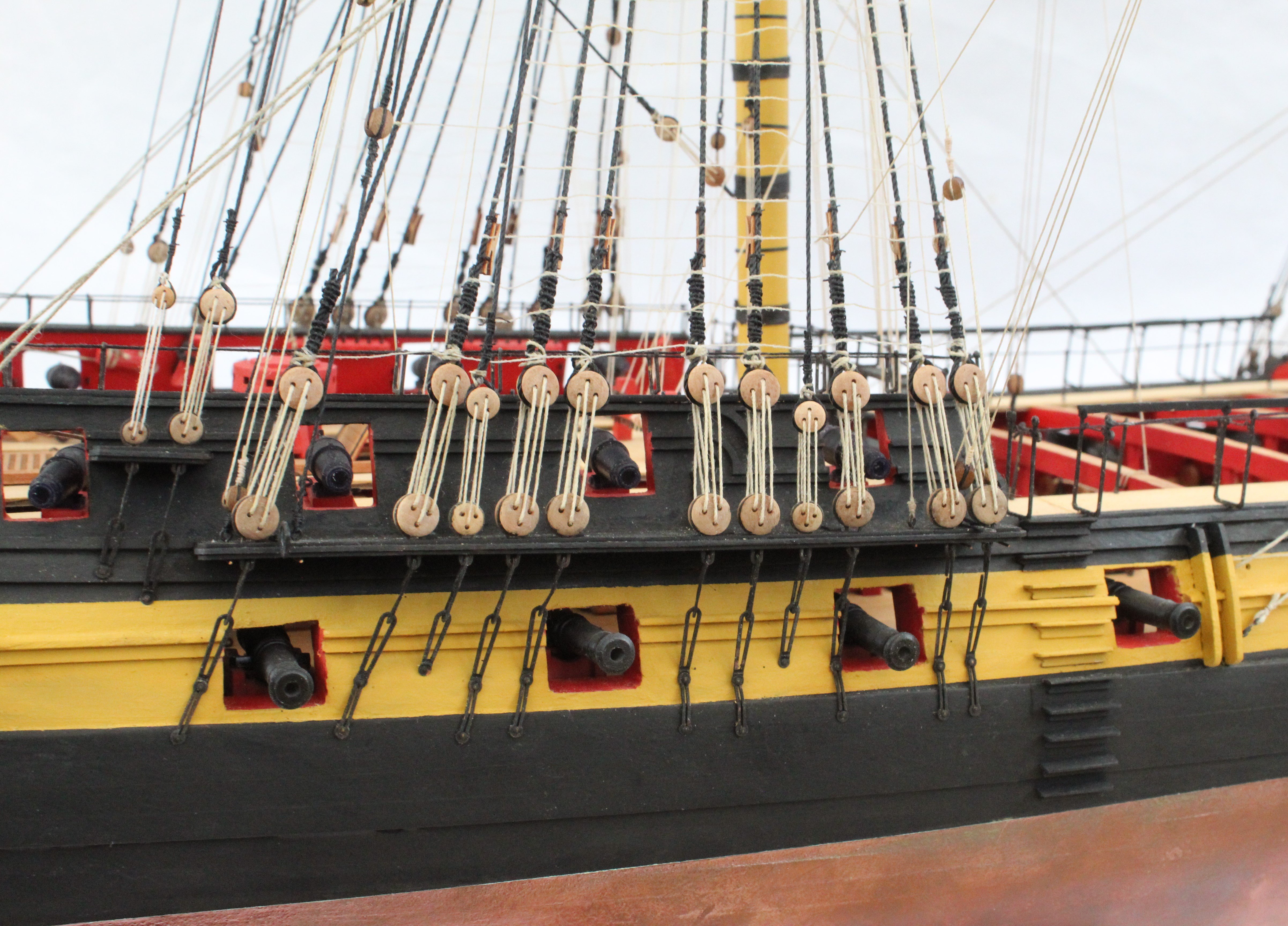
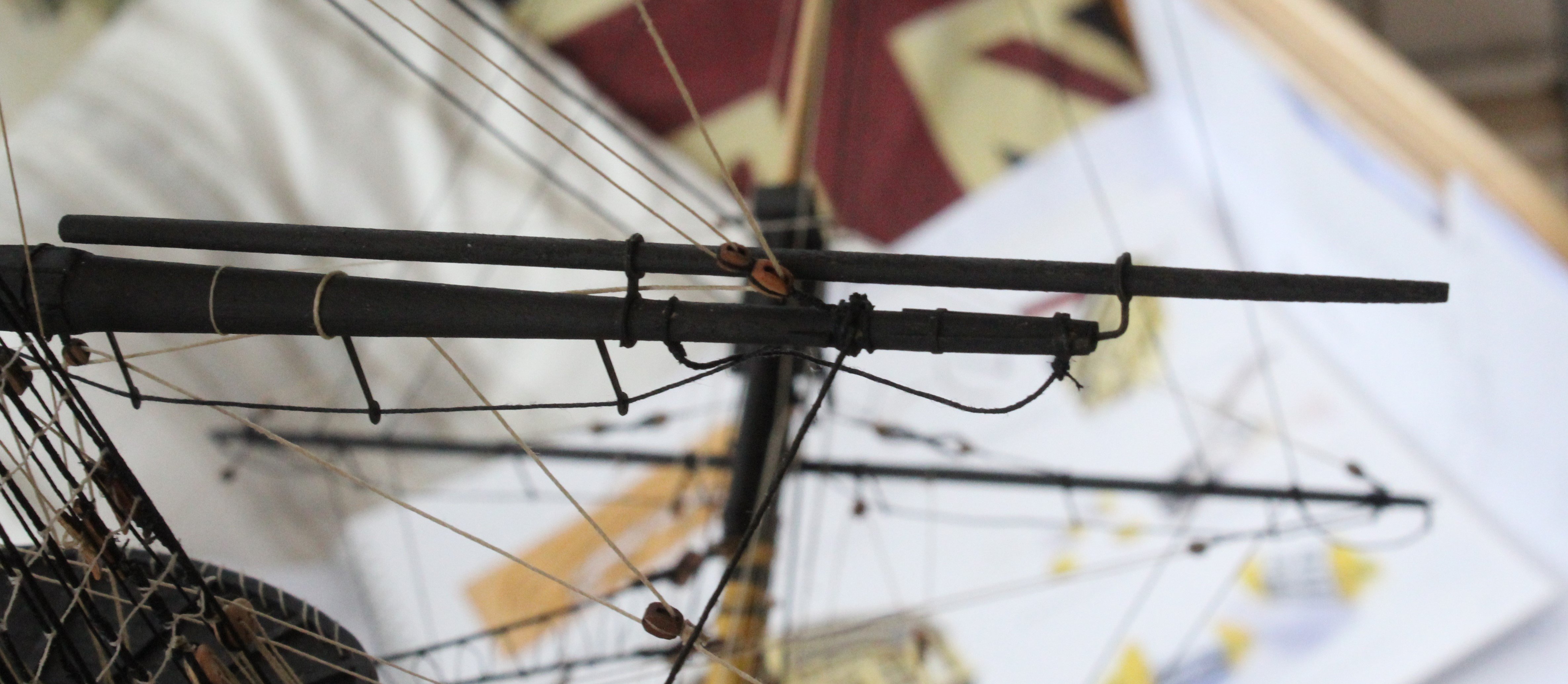
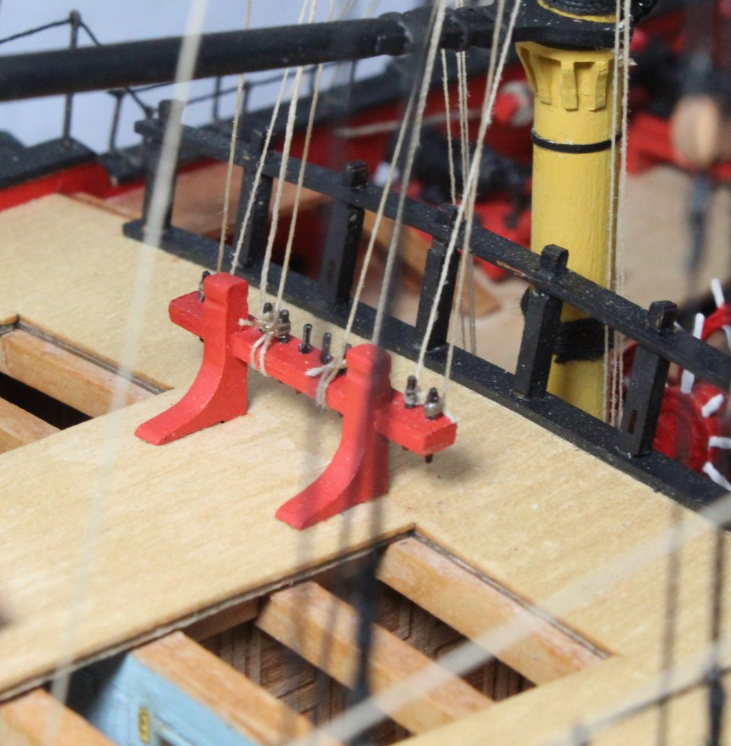
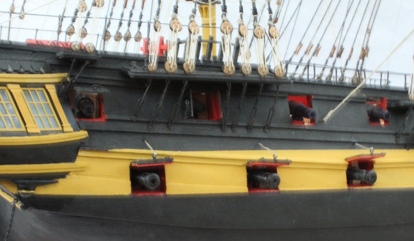
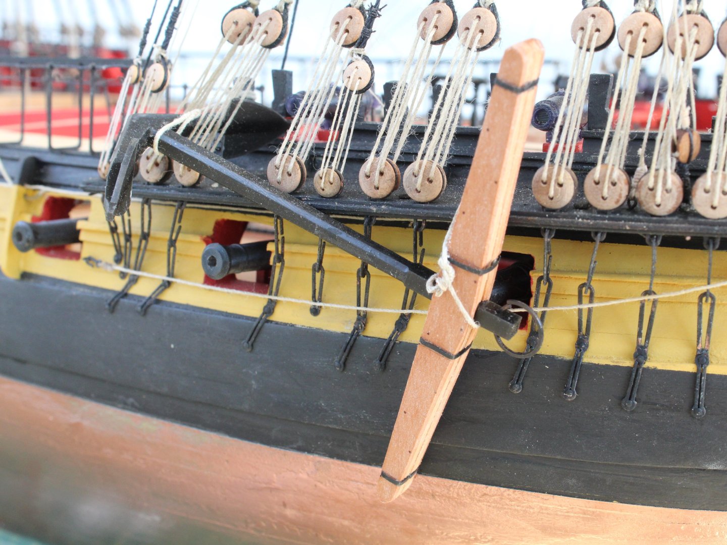
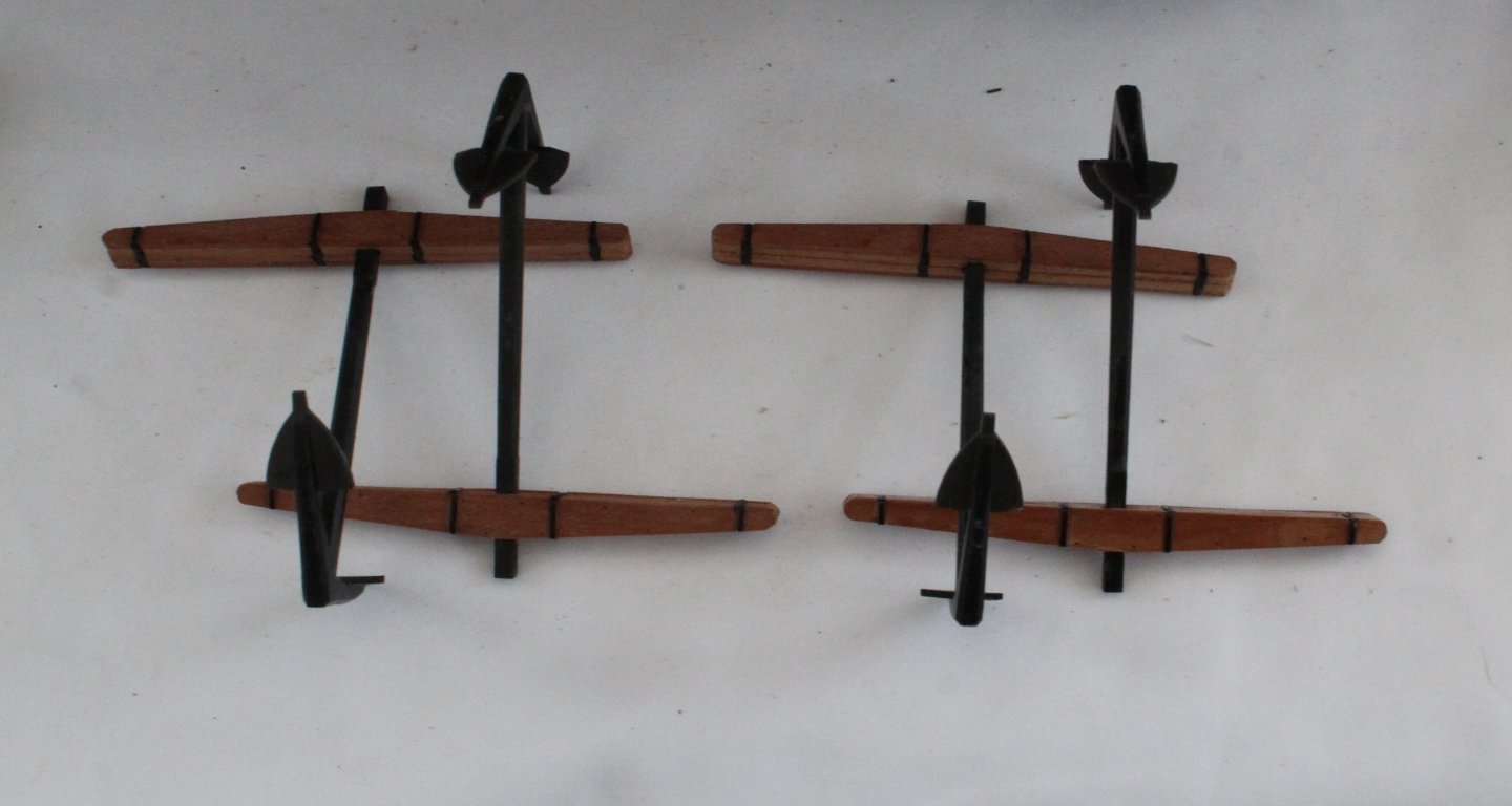
Bits and Pieces I spent today doing some bits and pieces as I near the completion the Indy. My first task today was to build the 4 off anchors. They are now ready to be installed. The various missing armaments were then glued in place. I also fully populated the various bitt racks with belaying pins. I thought I had misplaced the Indy's lanterns and ordered two new ones. Later on in the day I actually located the kit supplied lanterns. They have now been assembled, dry fitted to the Indy and the support frames painted. They are now ready be be installed. The final task today was to add the stunsail booms to the fore / main yards and fore / main topsail yards. Tomorrow I will add the anchors and lanterns to the Indy. I will then add the knotted footropes to the bowsprit and spritsail. The final task will be to assemble and mount the Indy of the display stand so she is ready for her final photo shoot. I have just ordered the HM Brig Adder which will be my next build. I will start a build log for the Adder once the kit has arrived.


- 587 replies
-
- 12
-
-
- Indefatigable
- Vanguard Models
- (and 1 more)
-
Look fabulous. Great work as always Jim. I have already earmarked this as my next build after the HM Brig Adder which I will be starting in the next few days.
- 76 replies
-
- 4
-
-
- Harpy
- Vanguard Models
- (and 1 more)
-
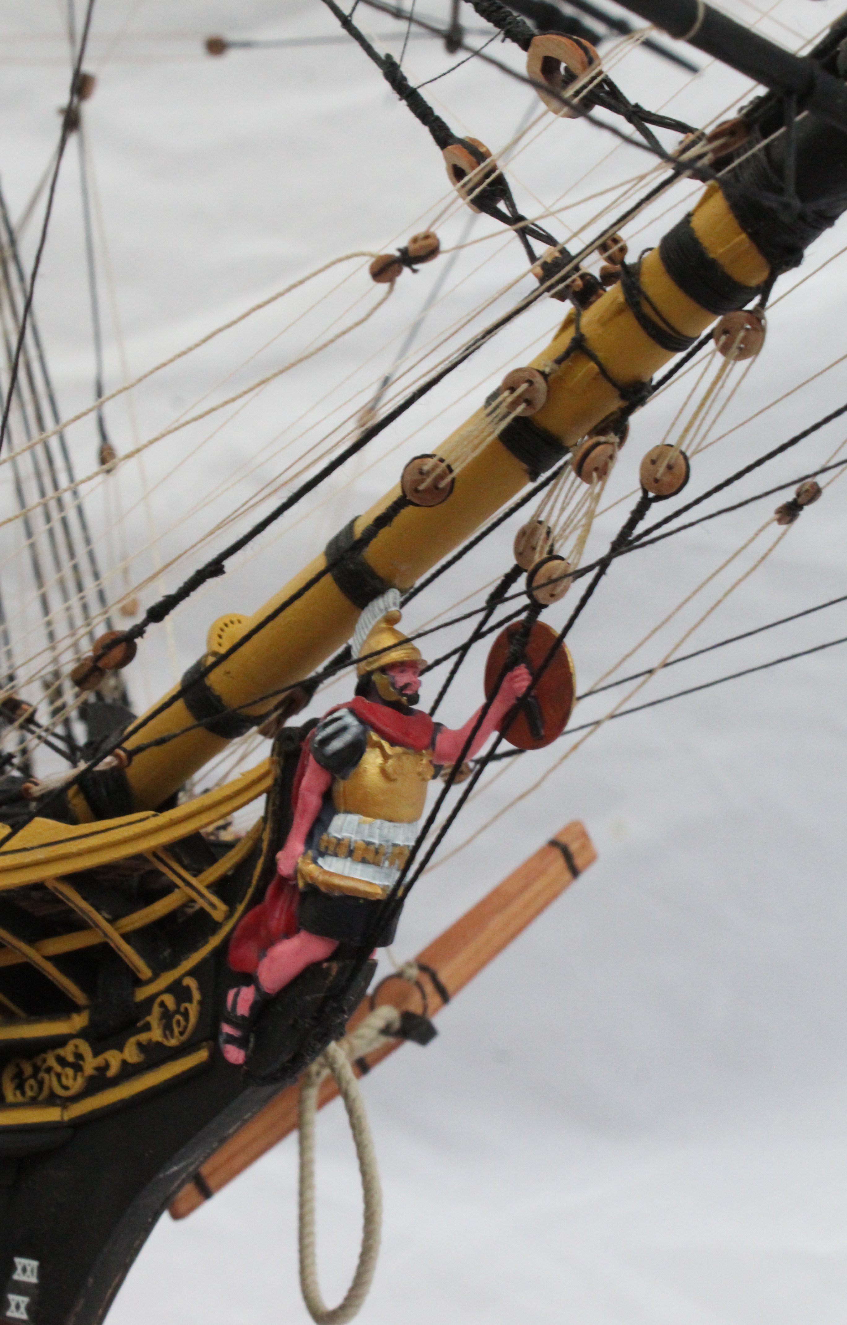
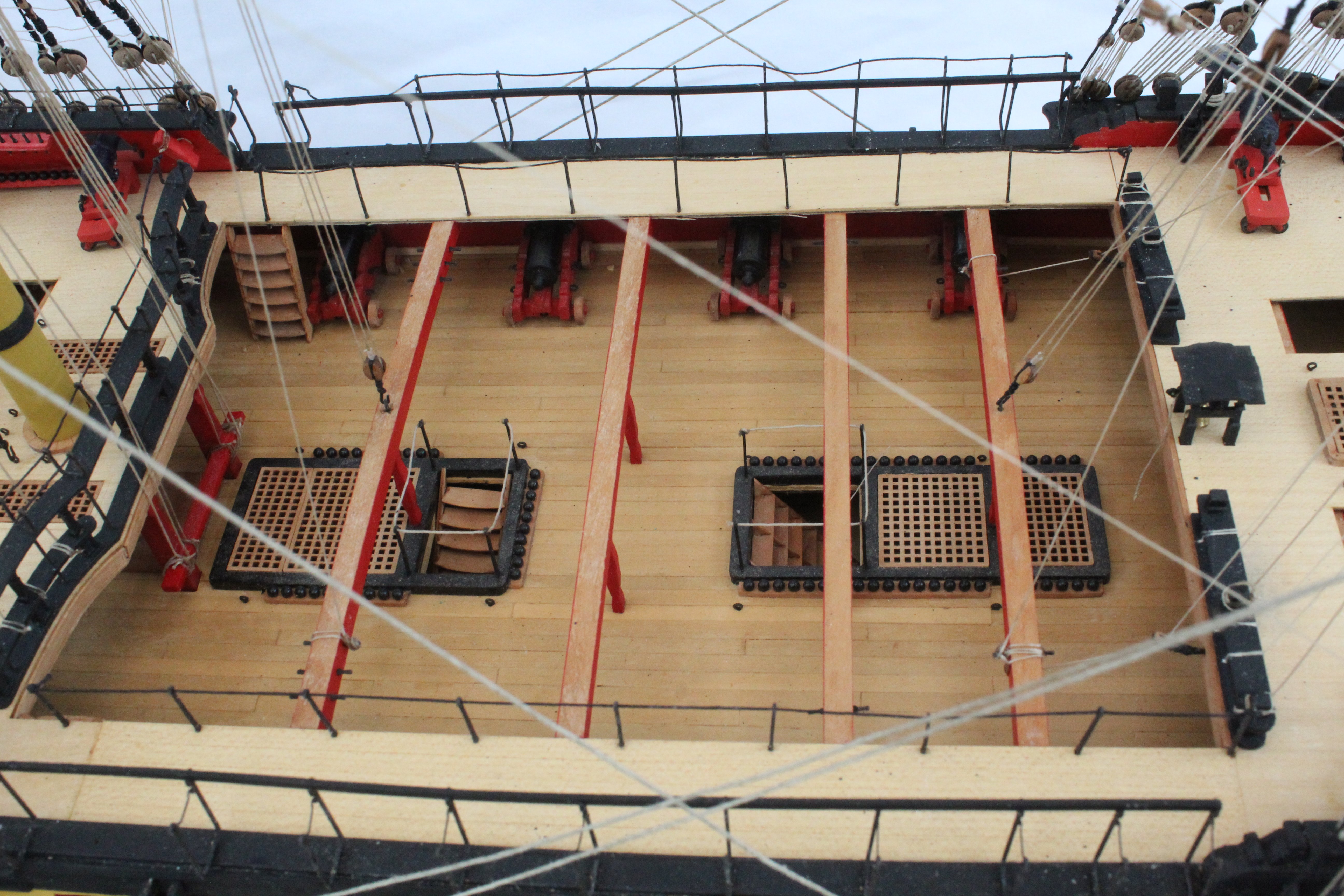
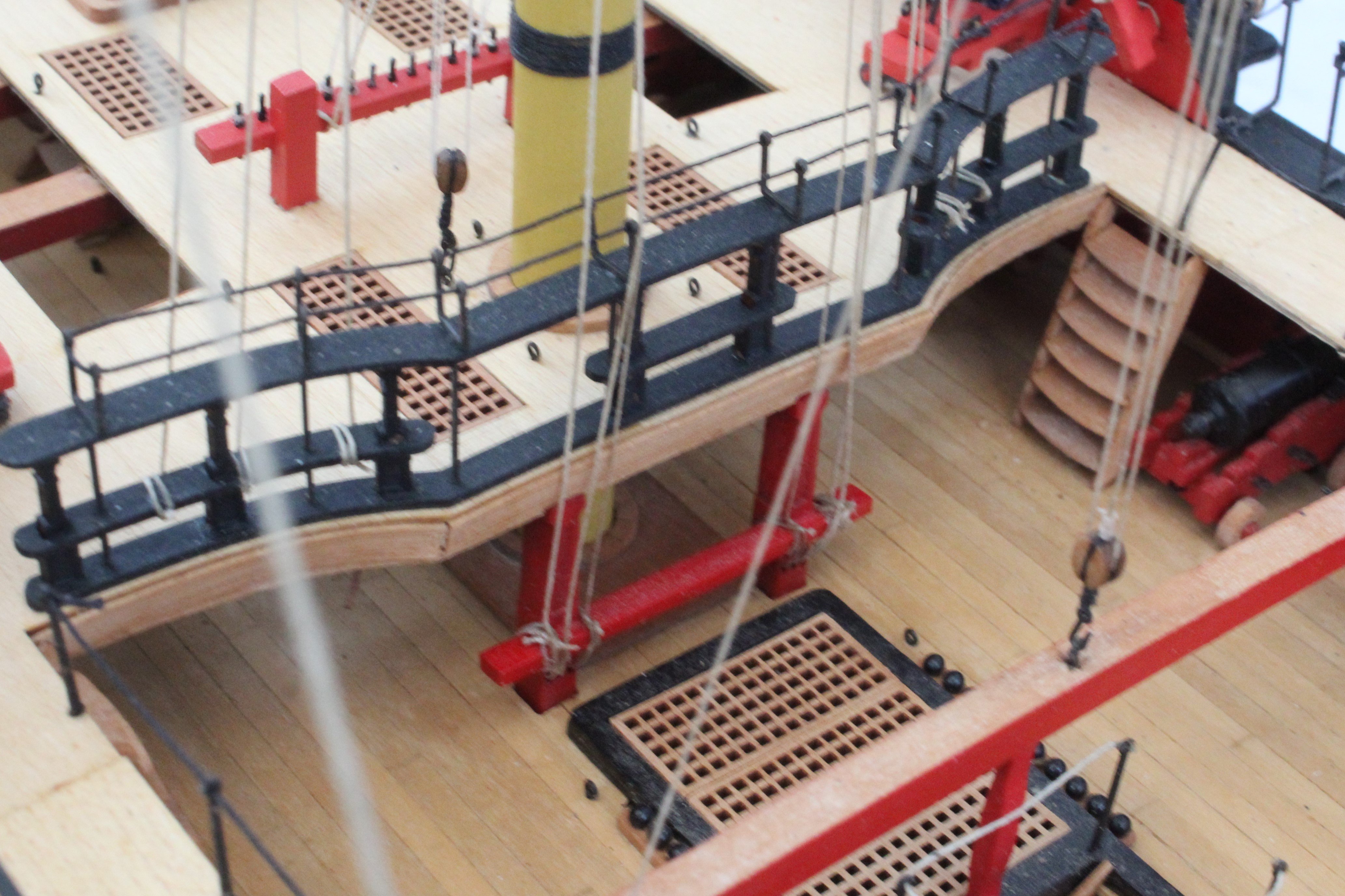
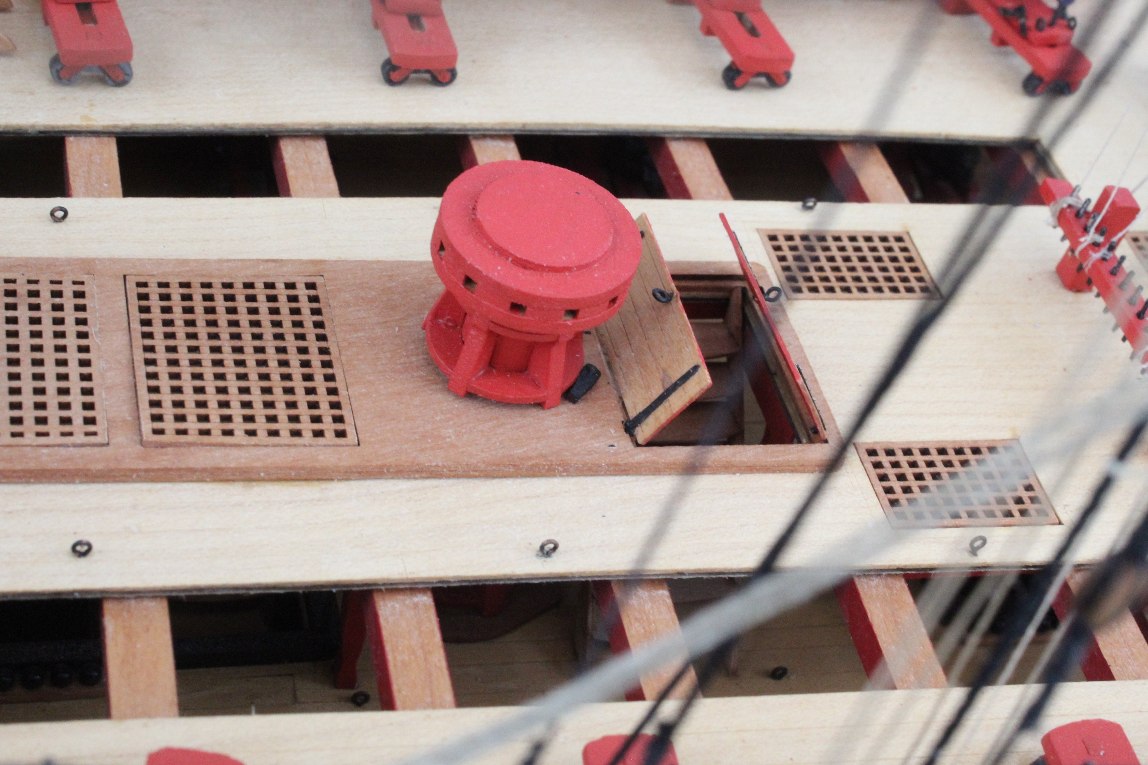
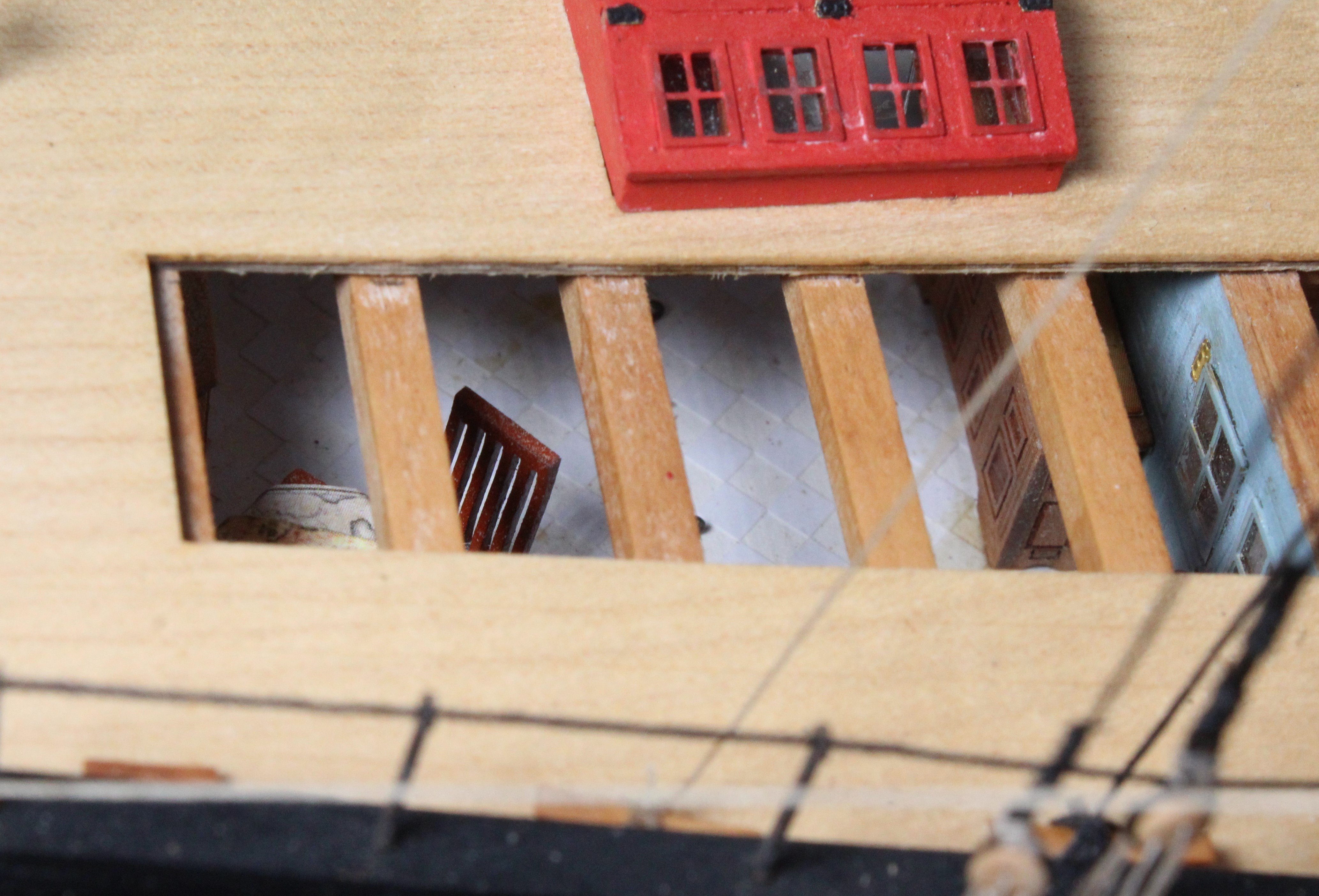
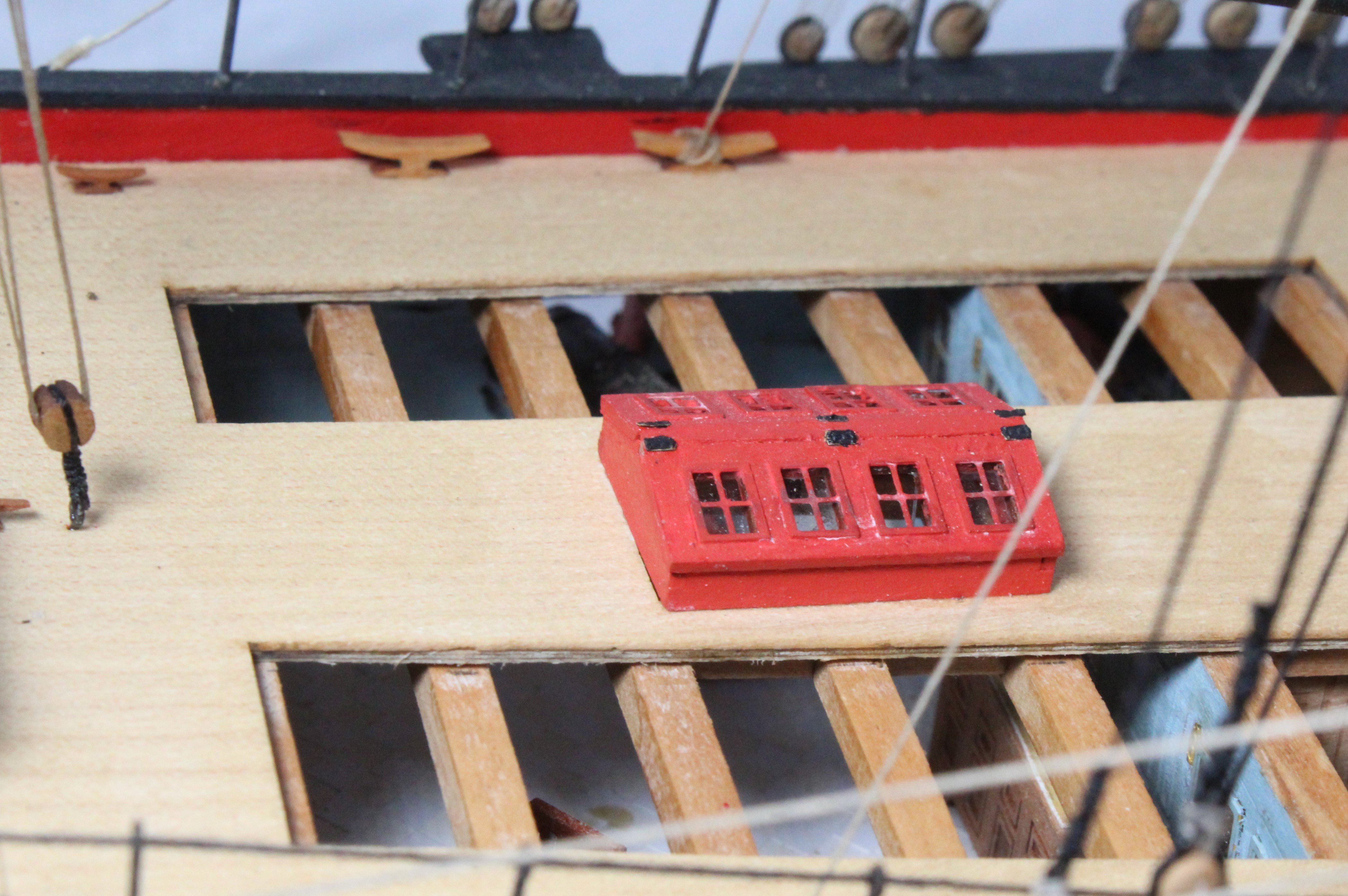
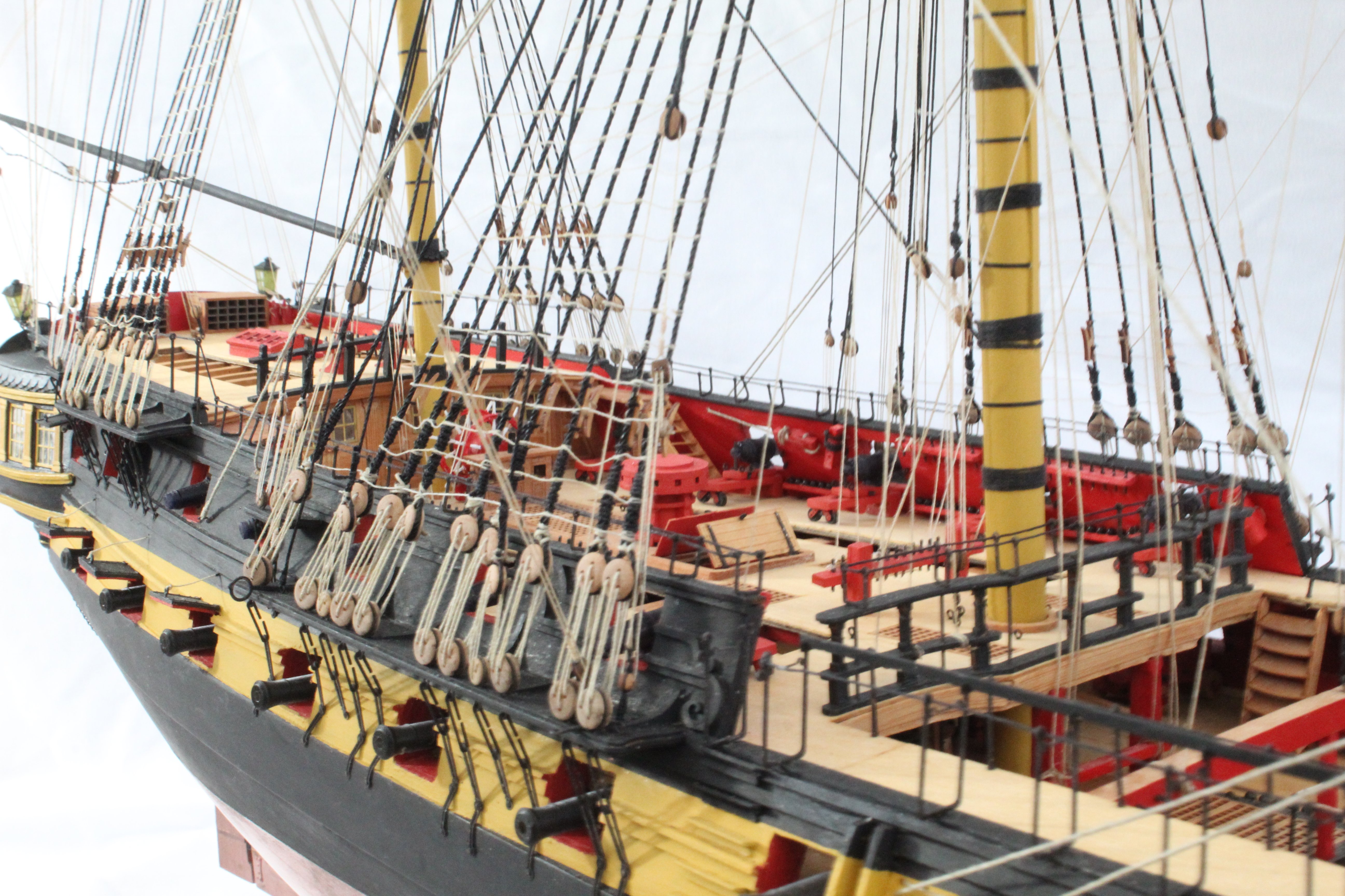
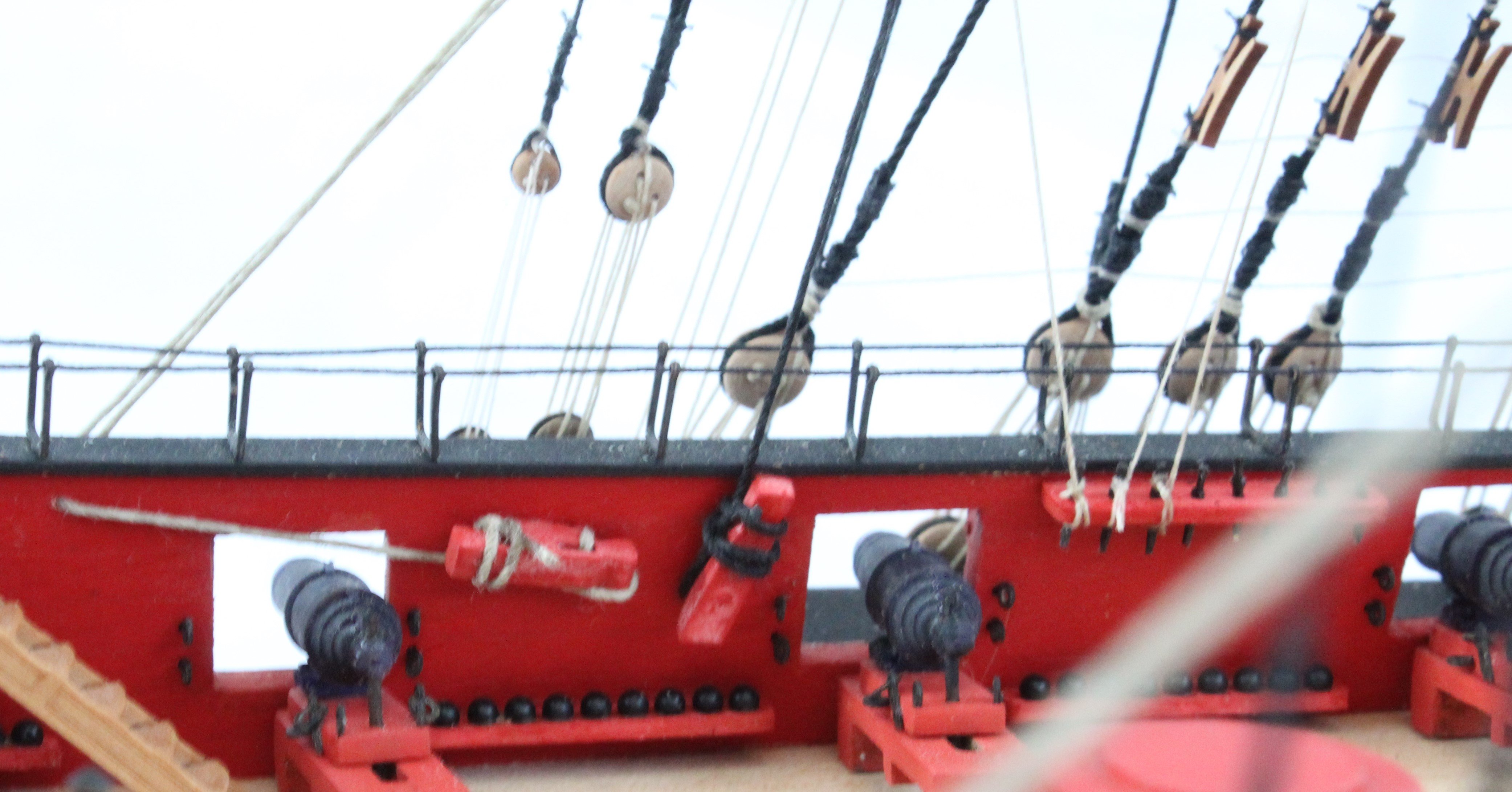
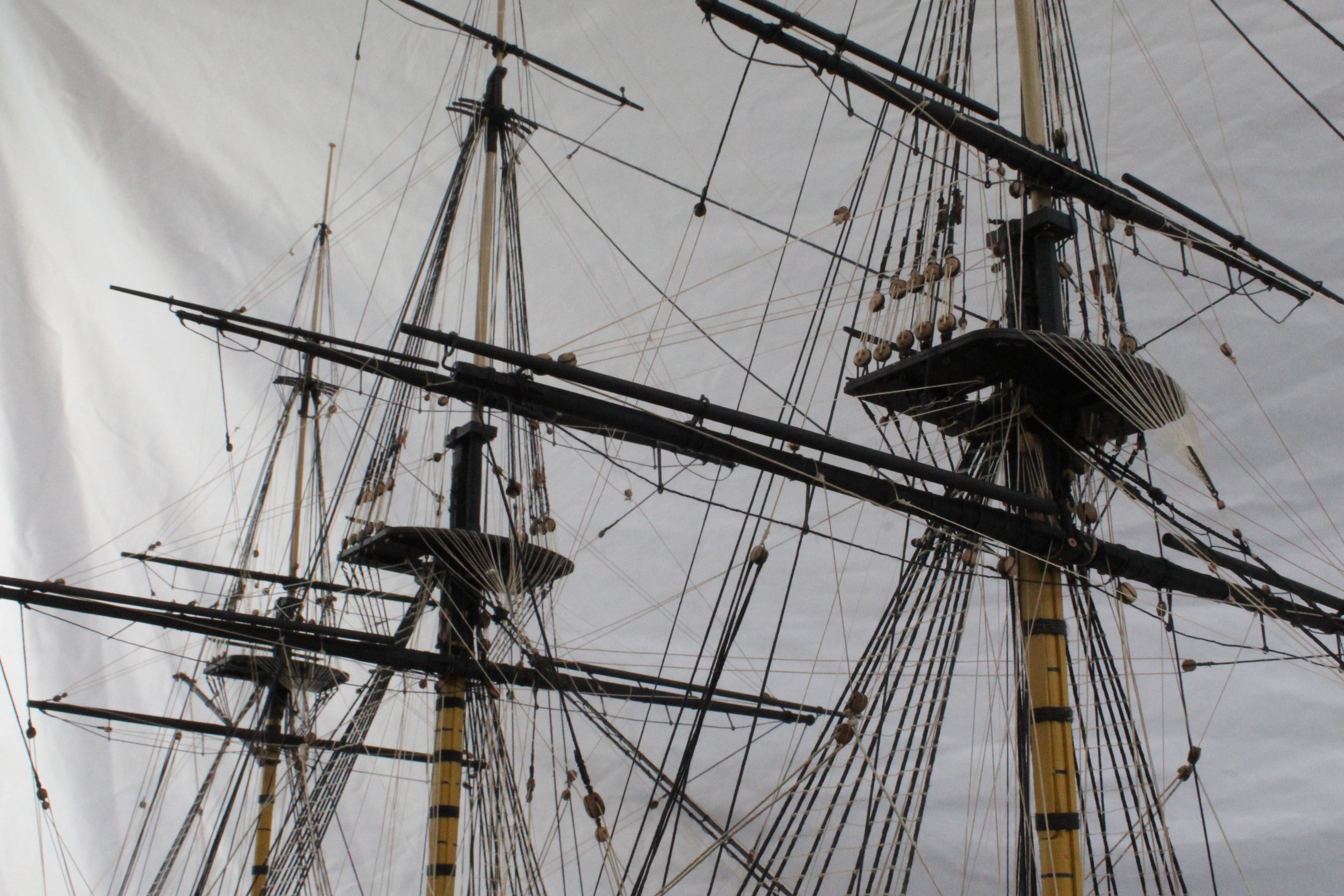
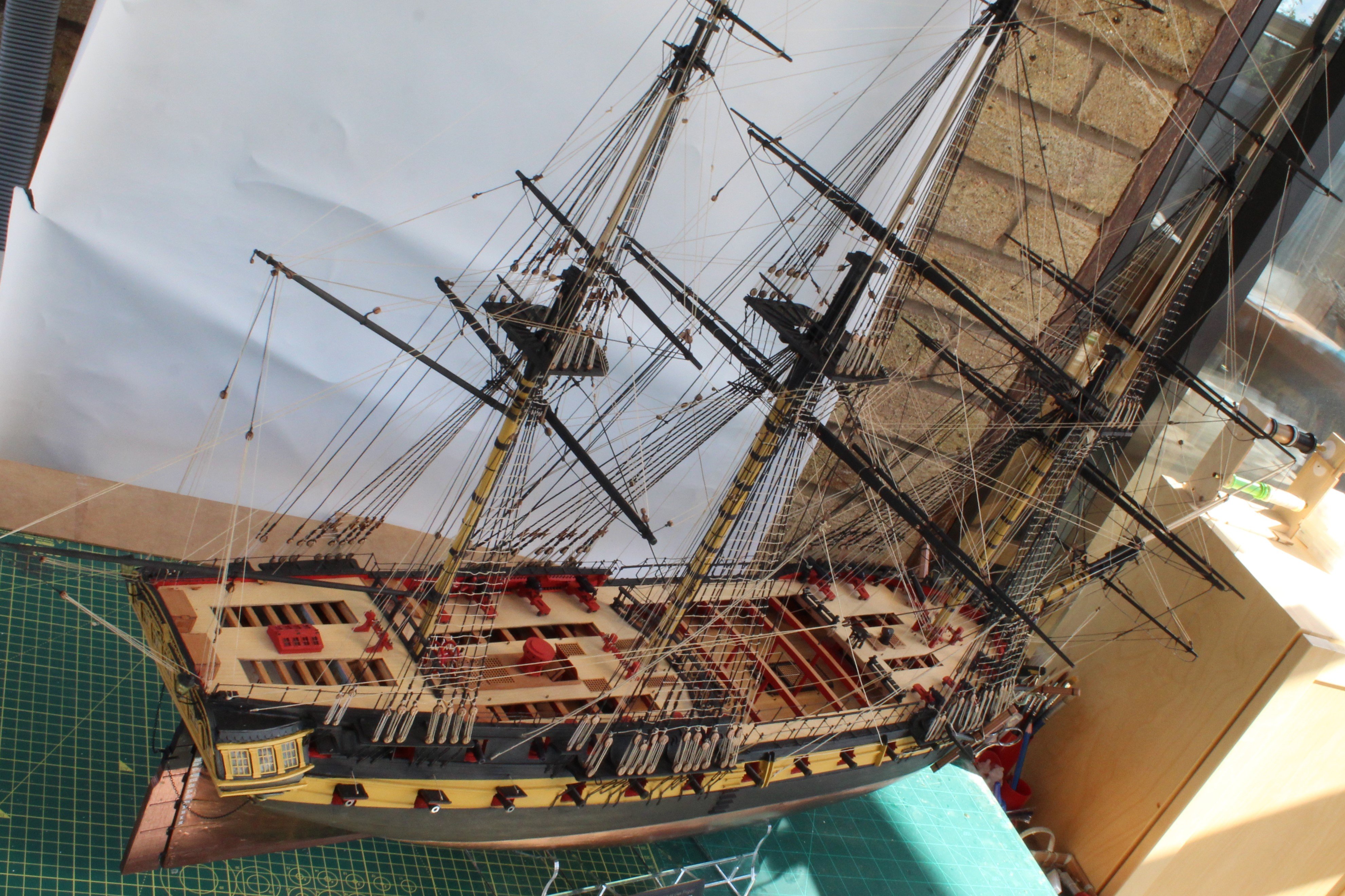
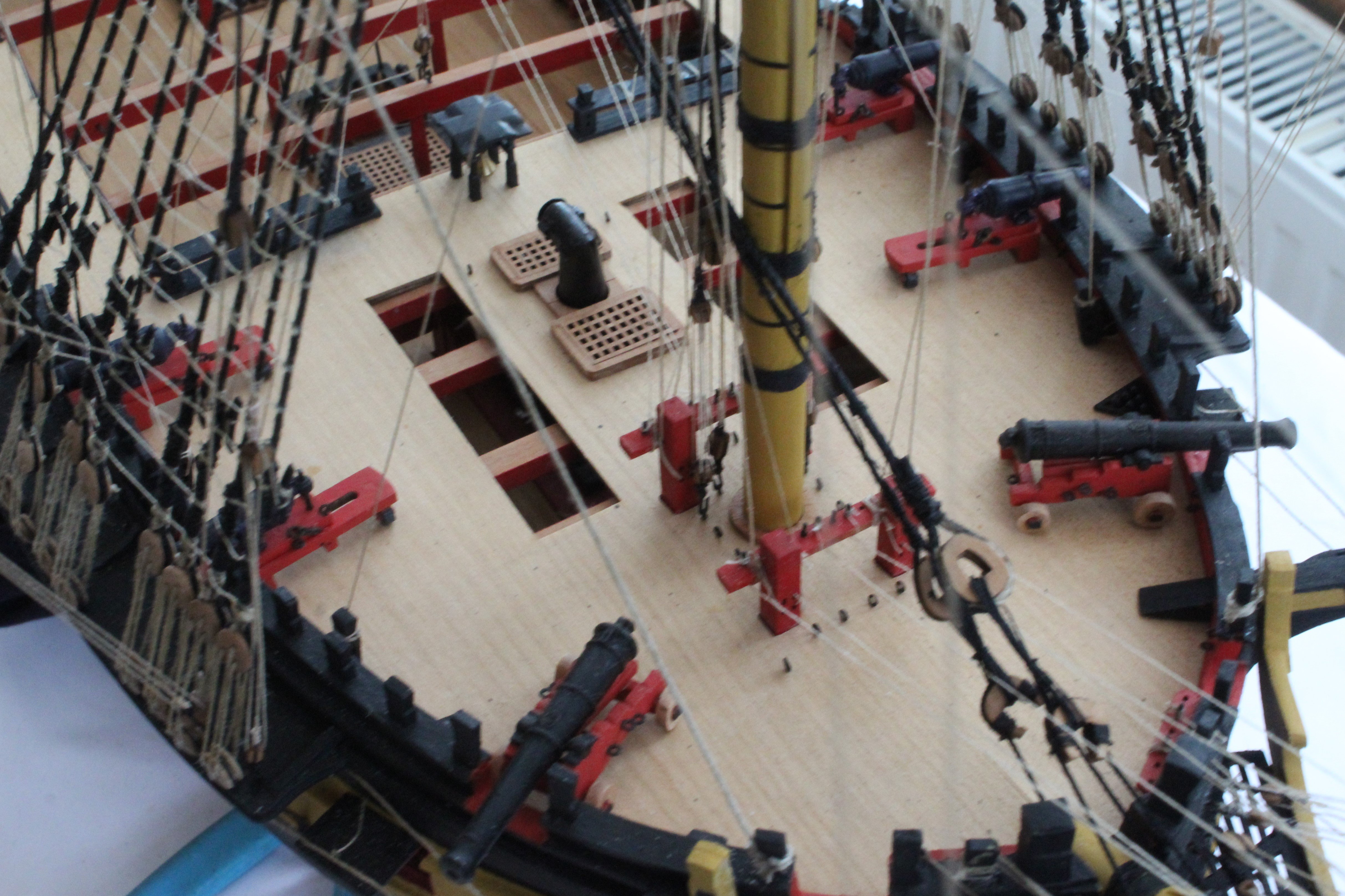
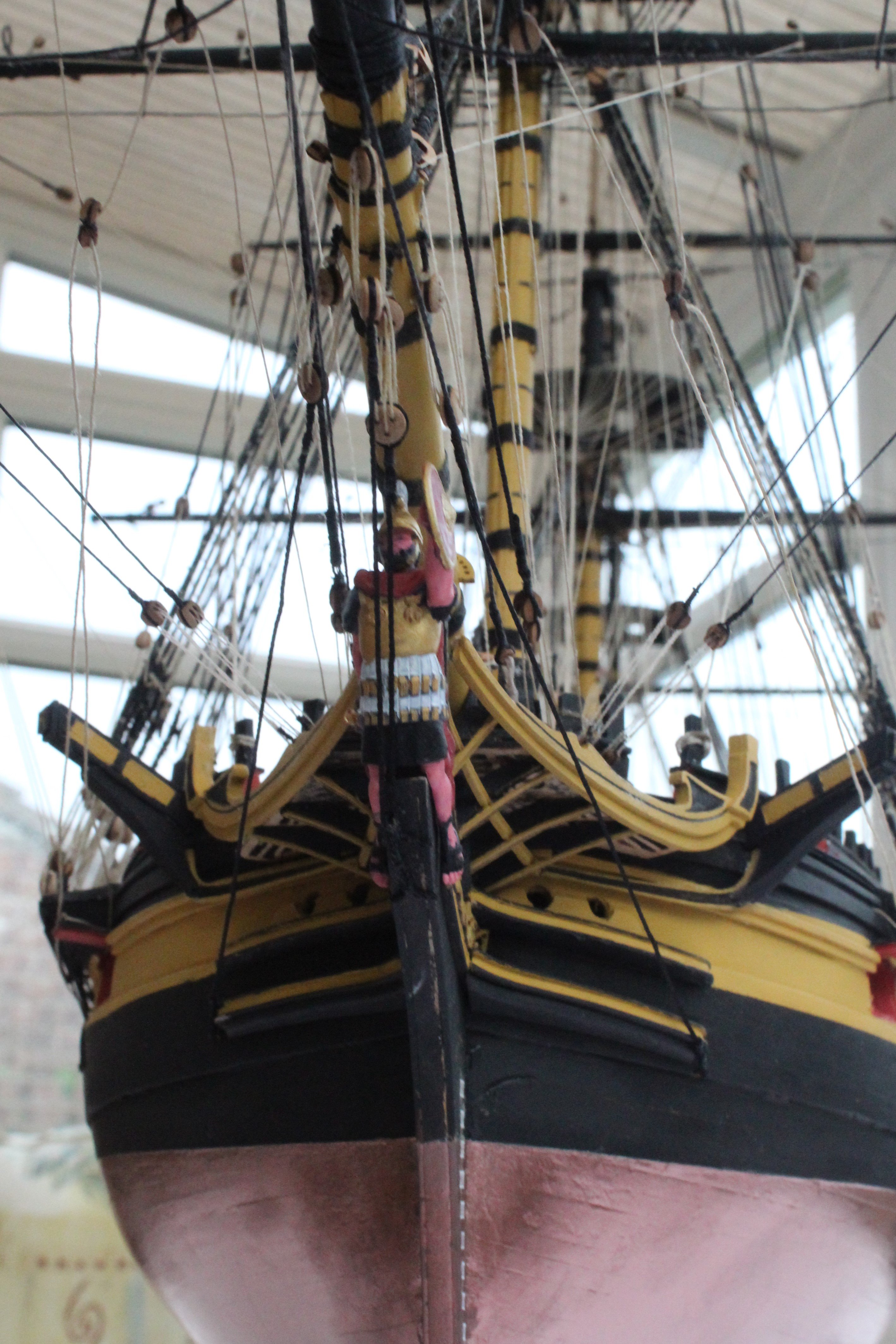
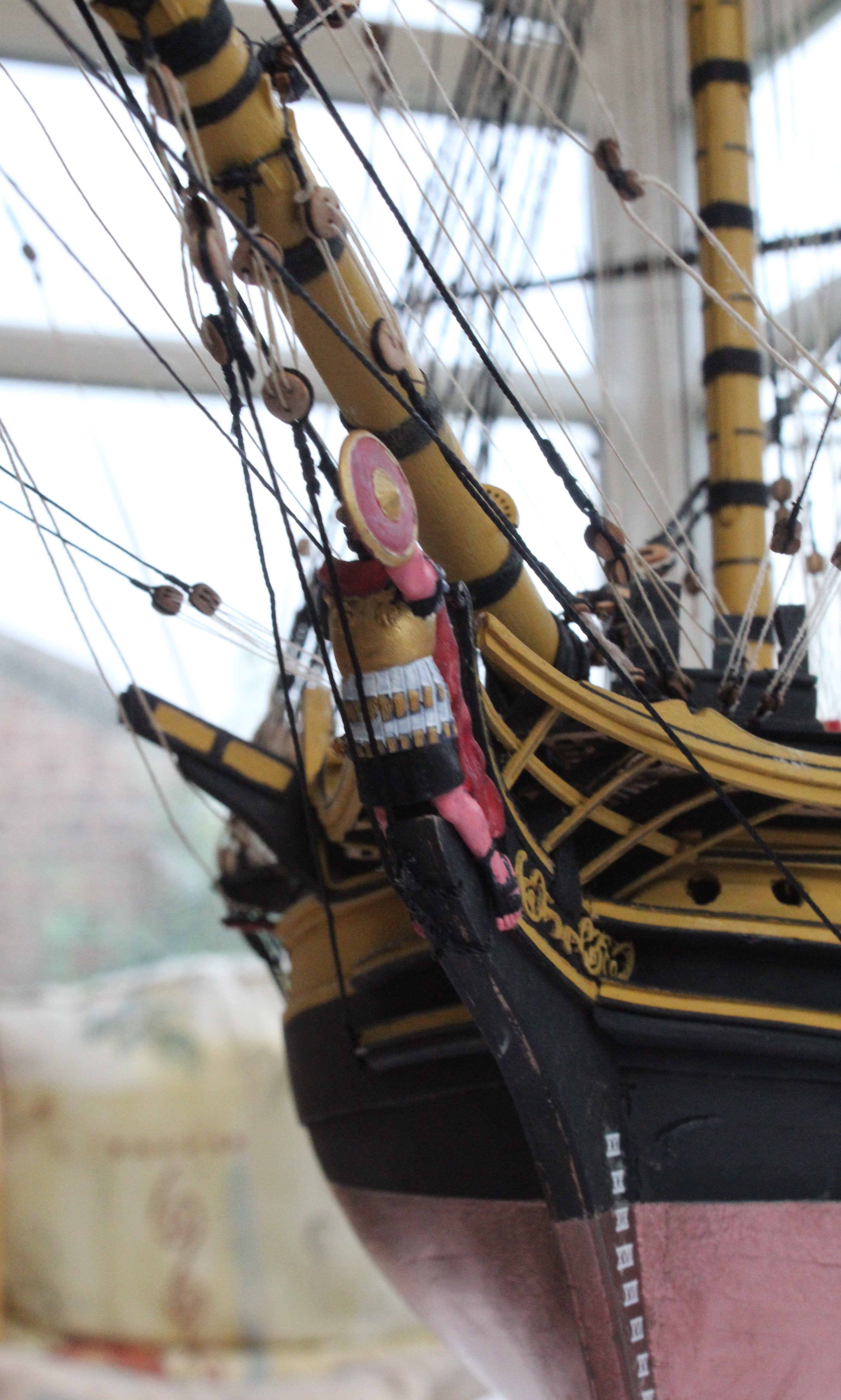
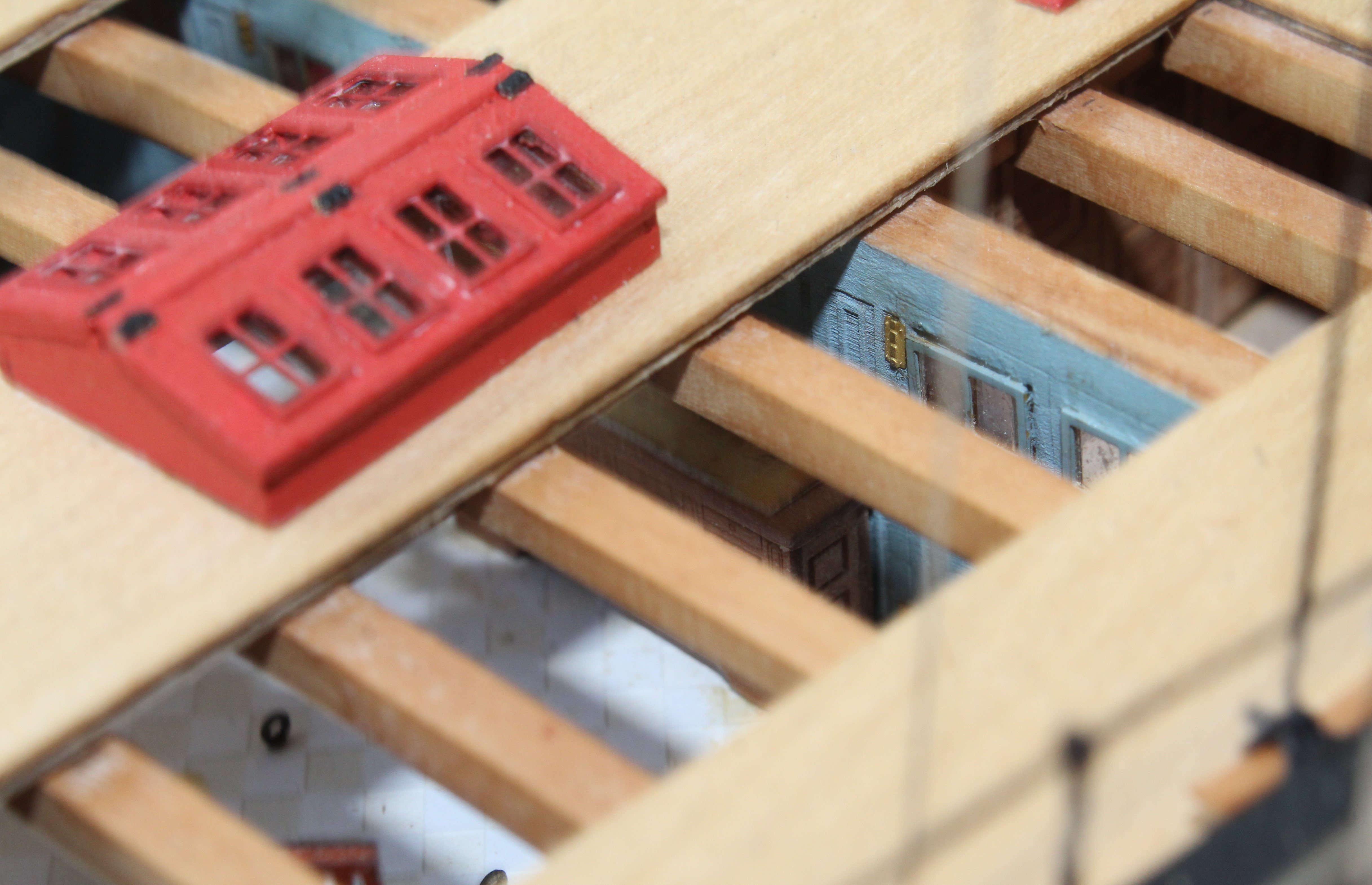
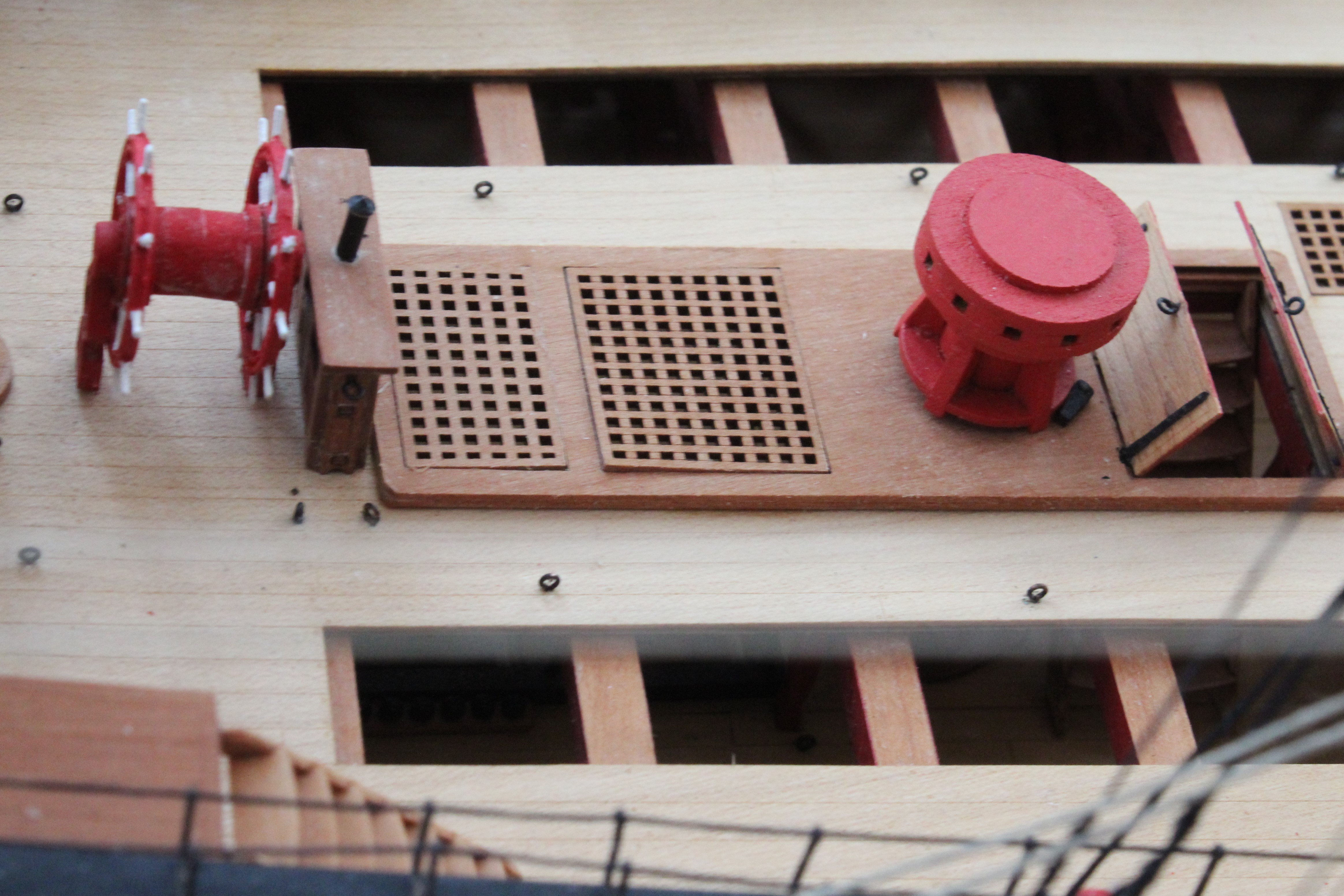
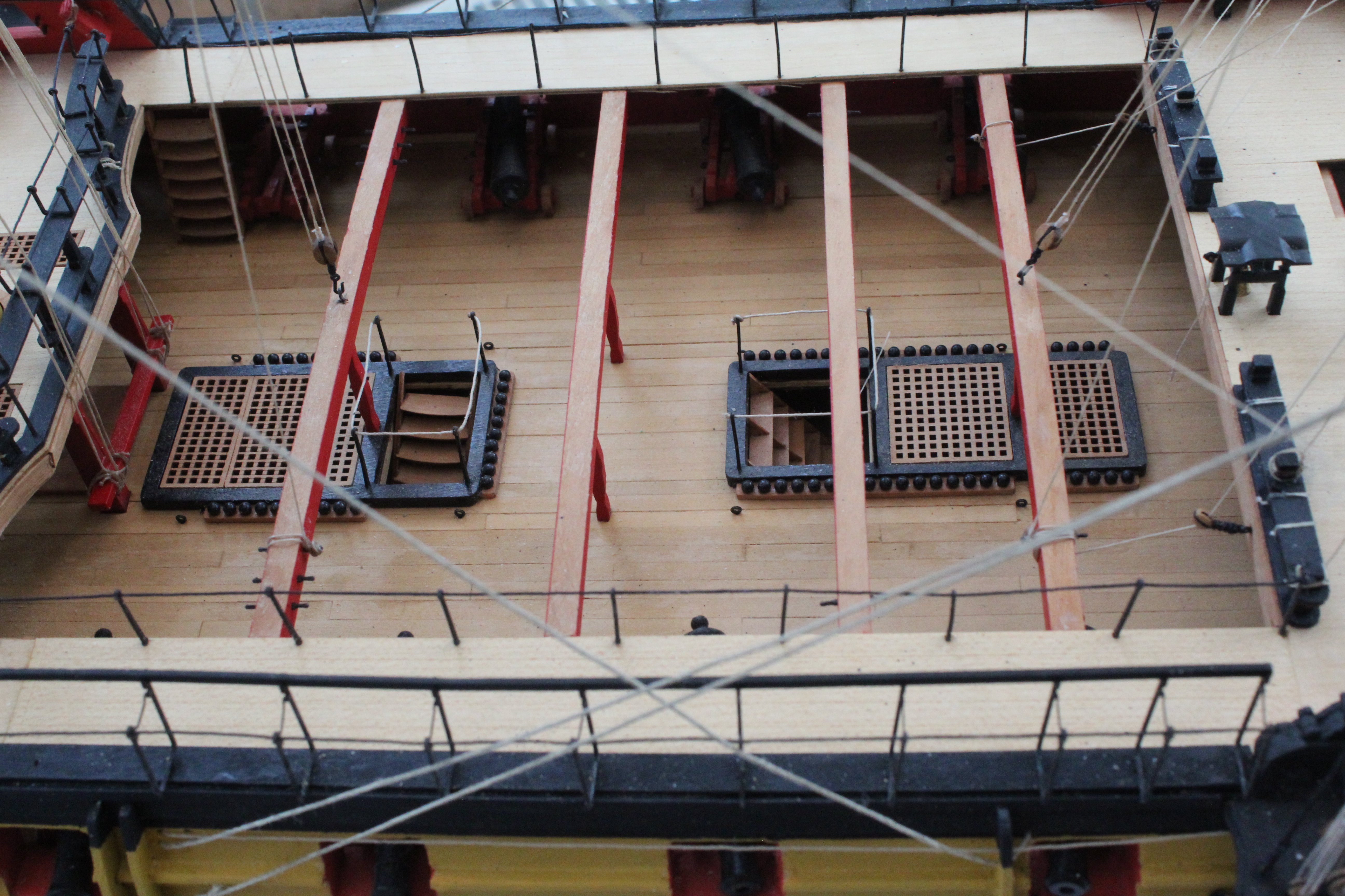
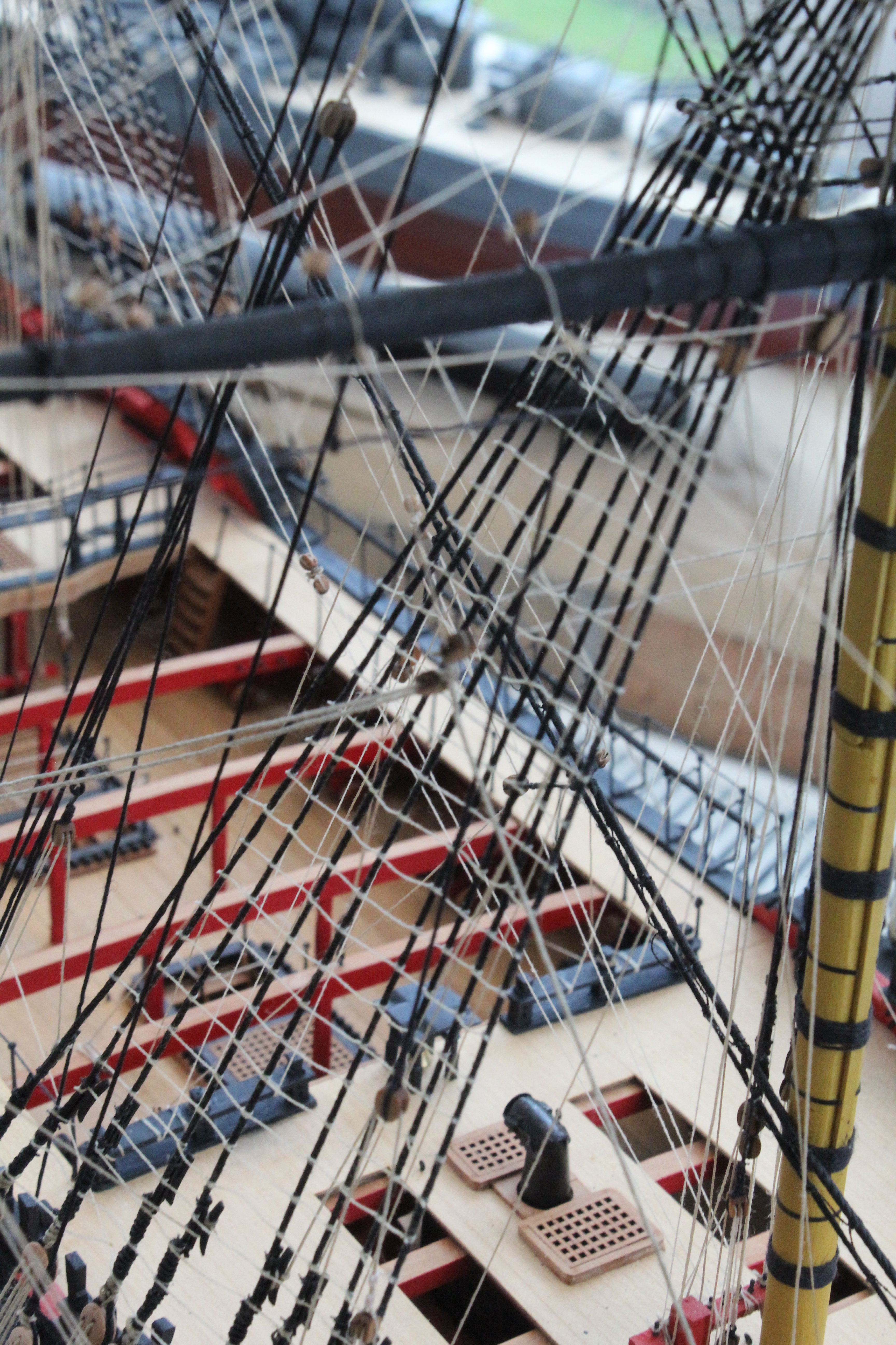
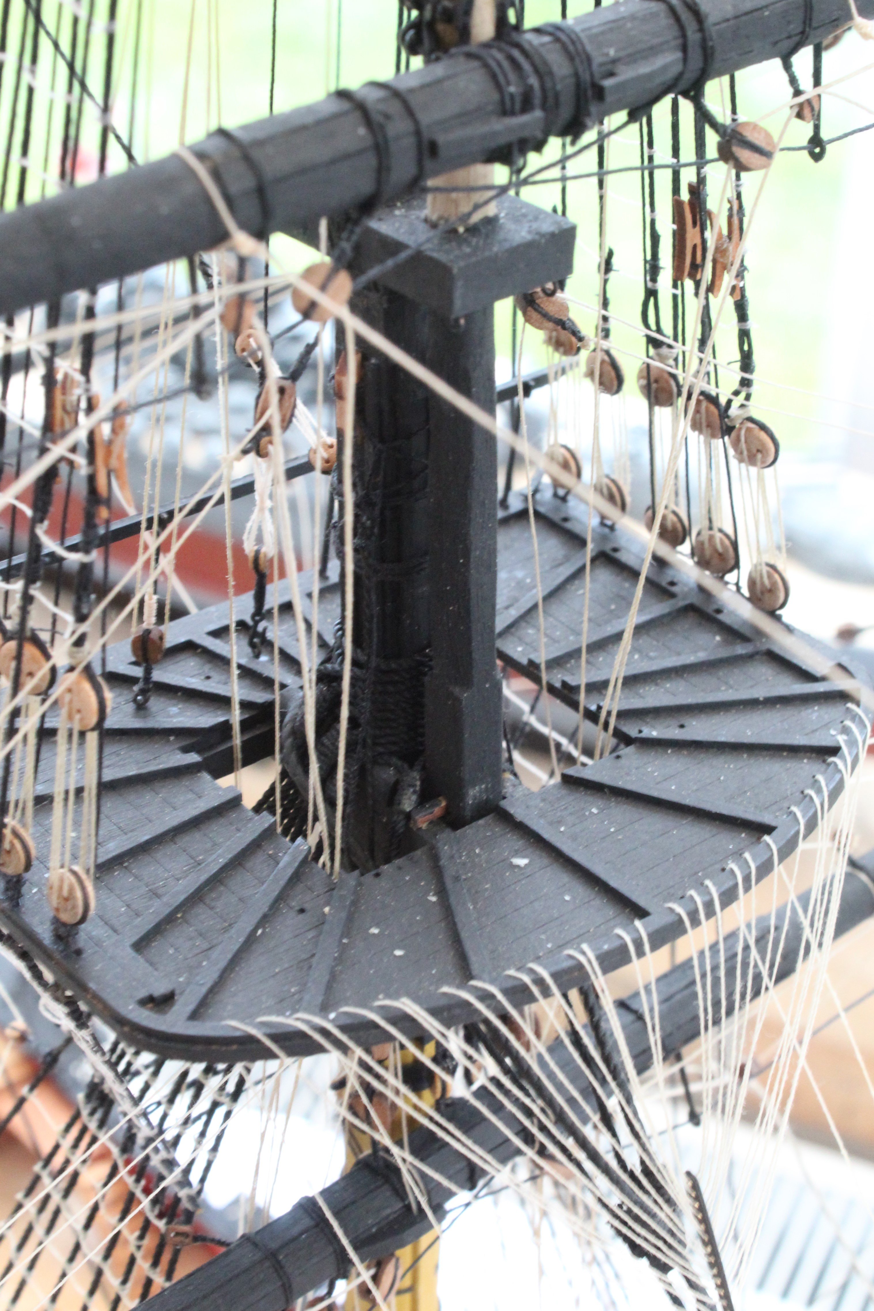
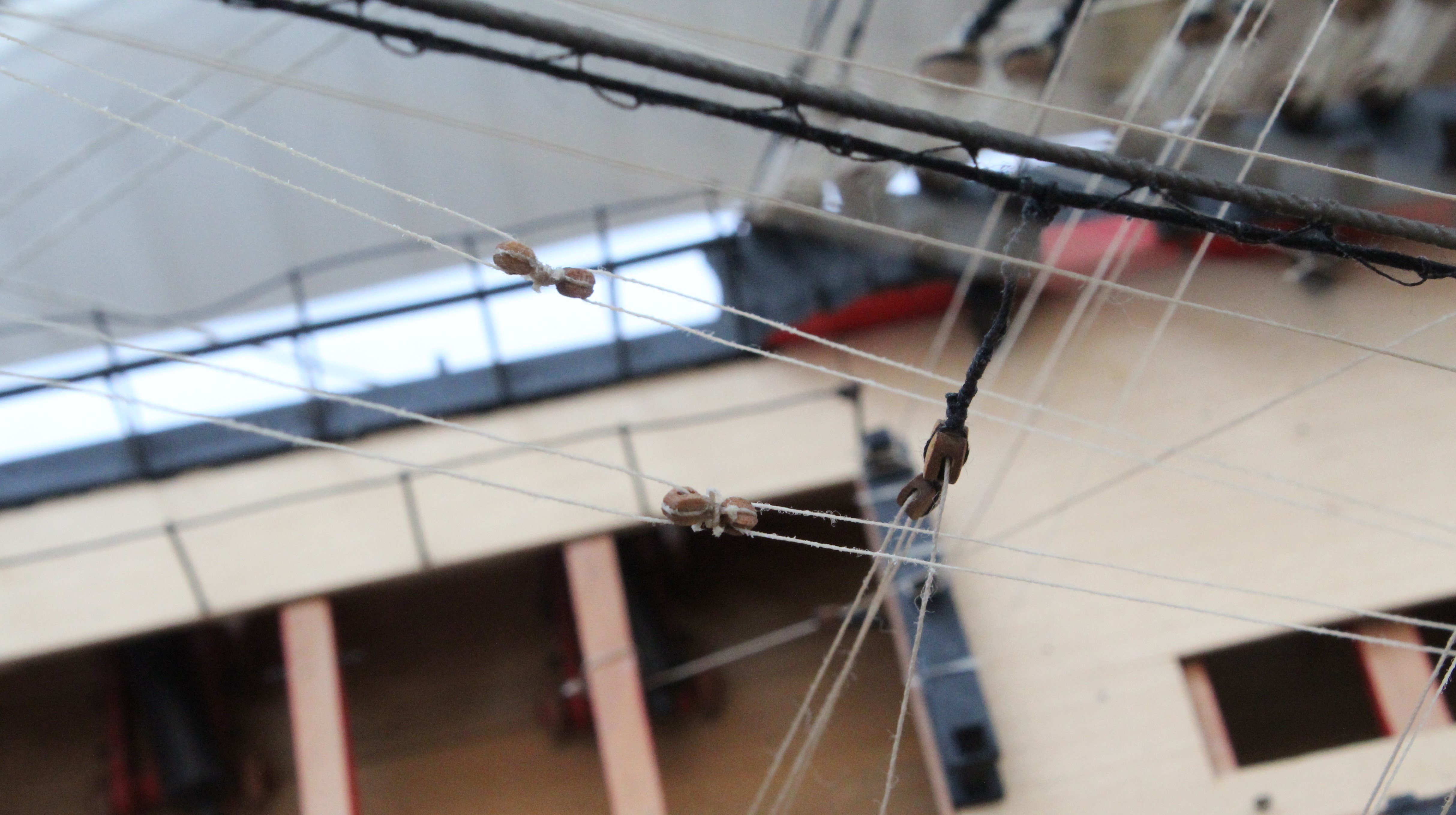
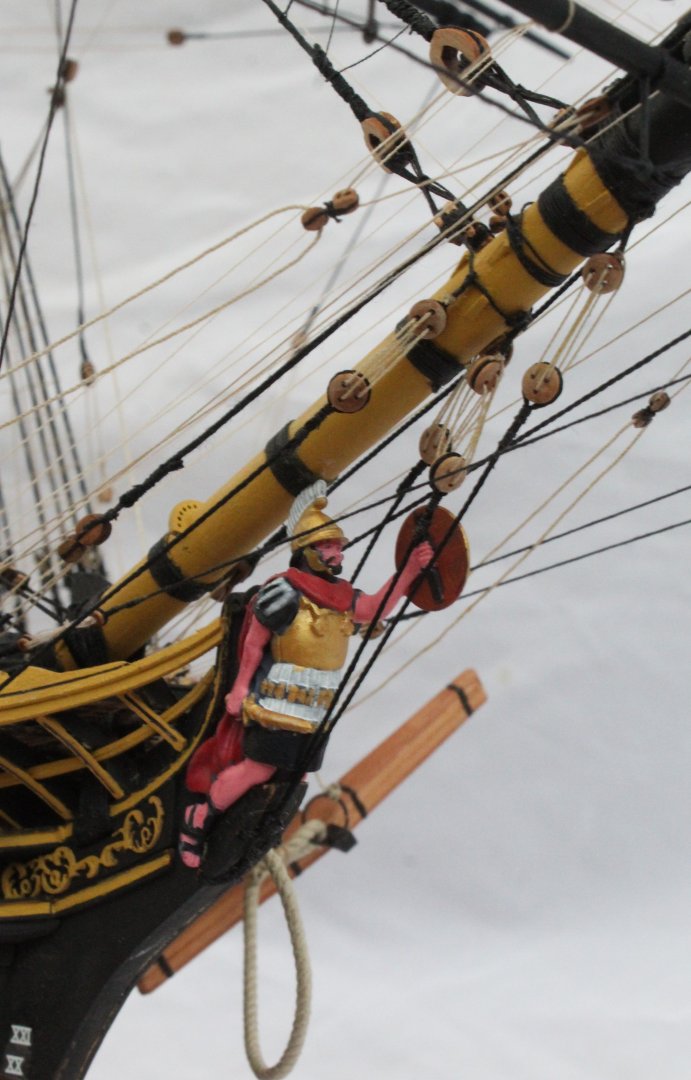
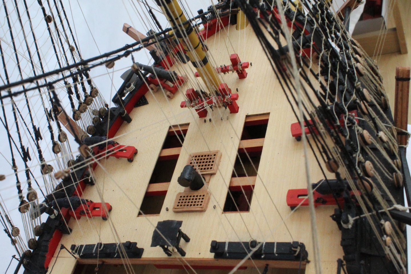
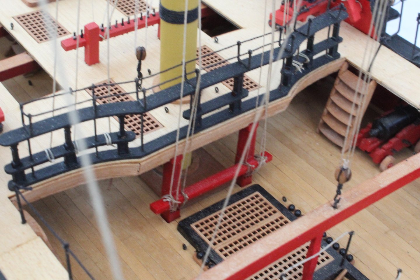
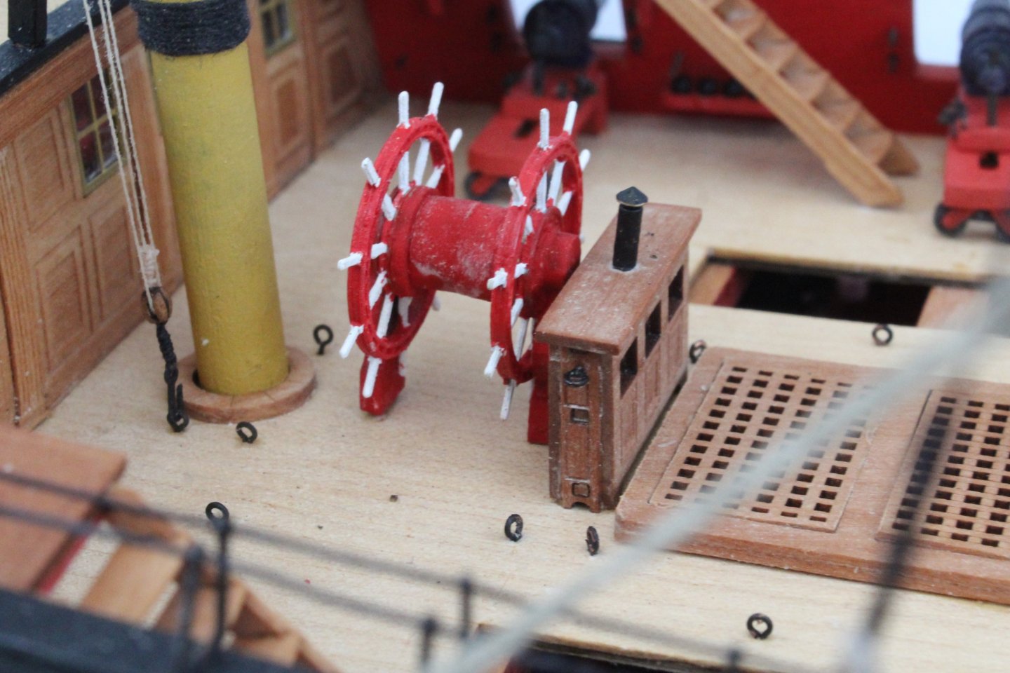
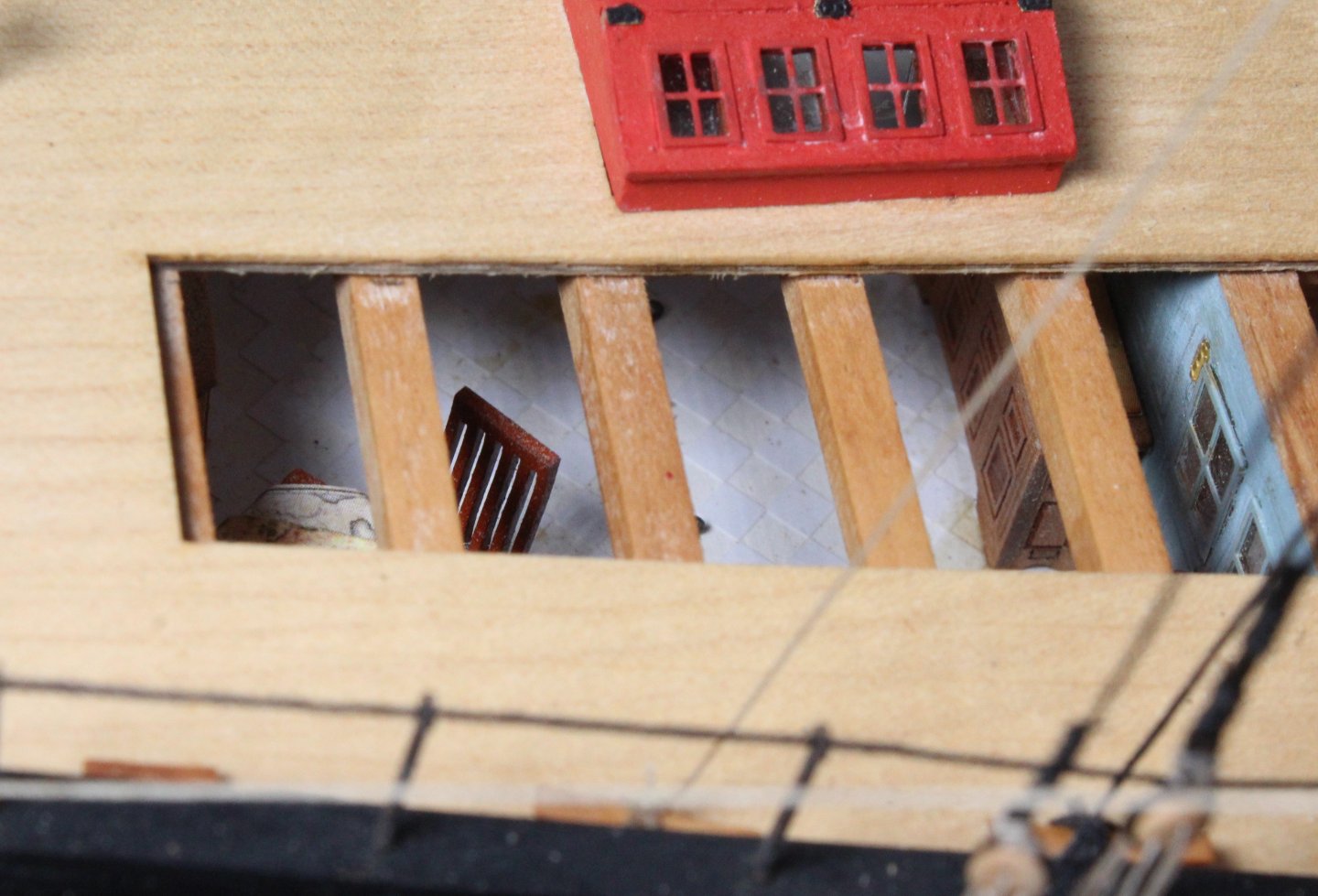
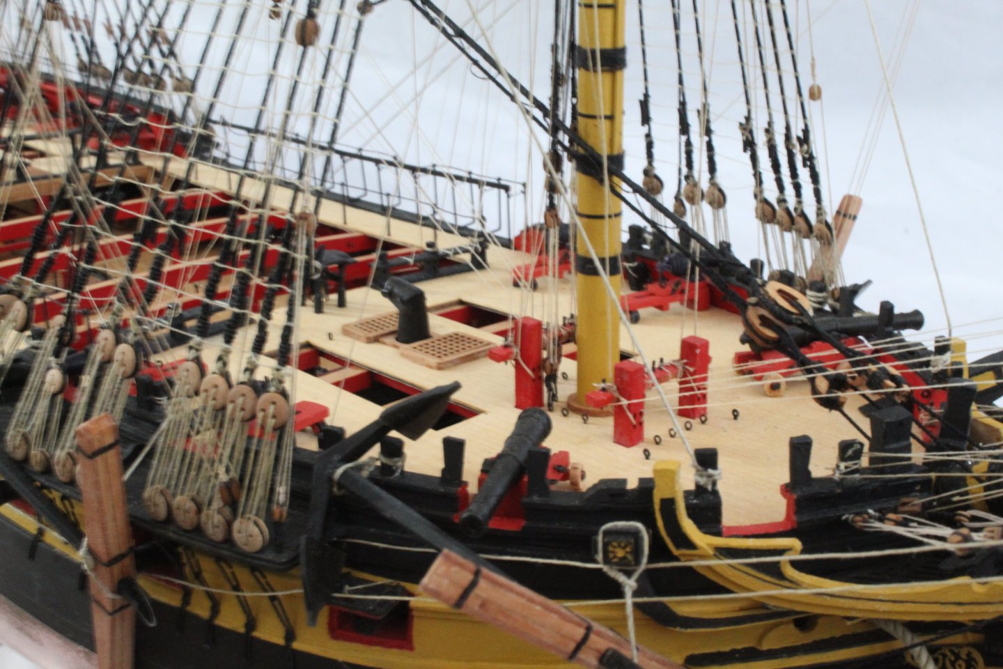
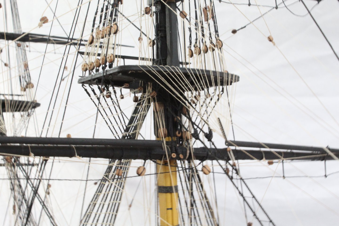
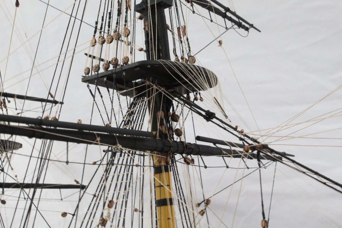
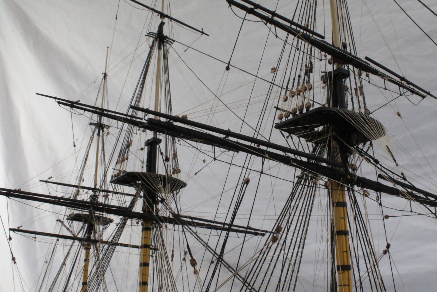
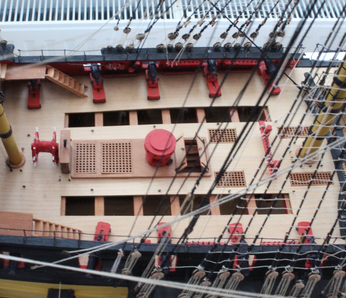
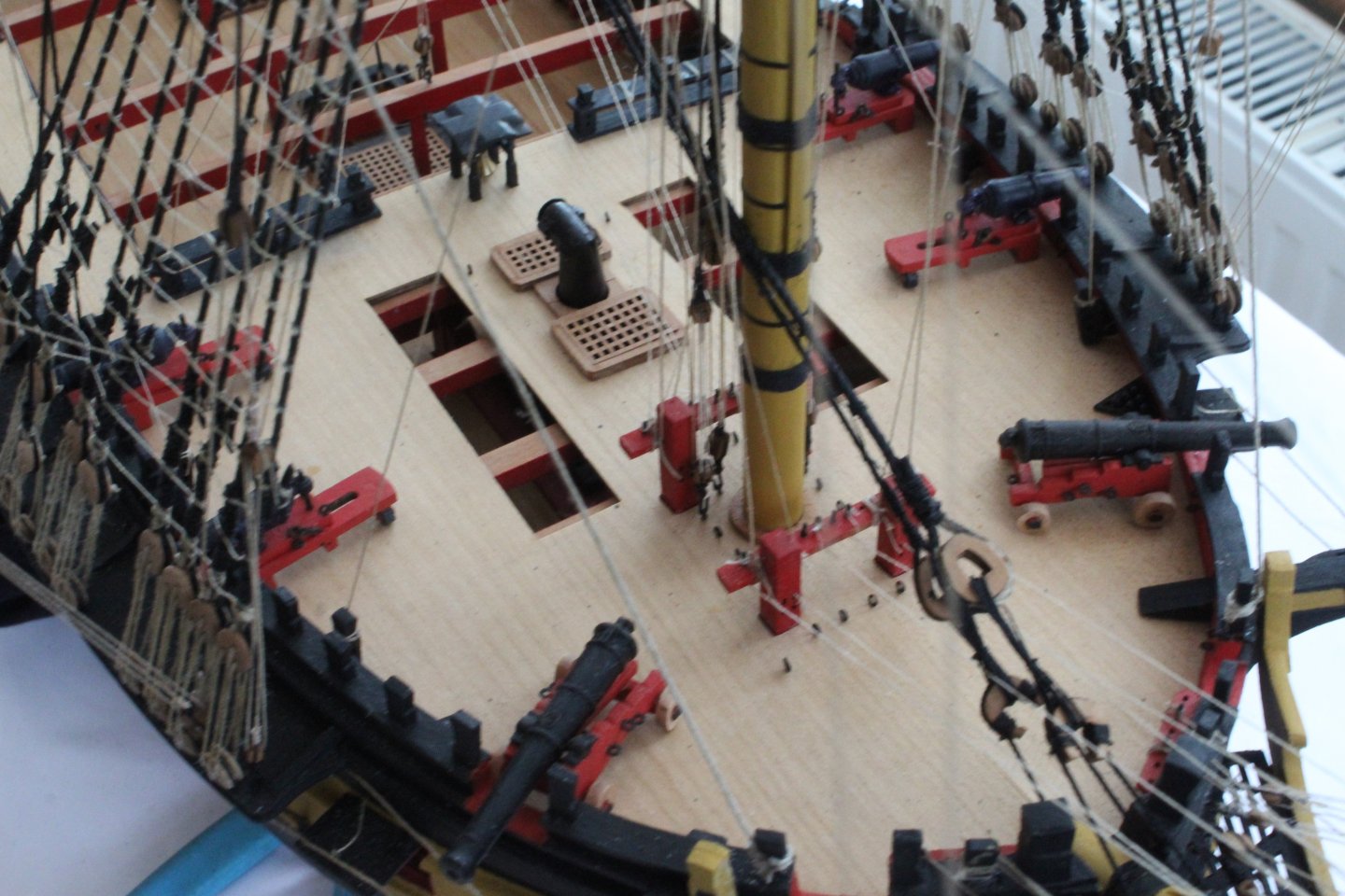
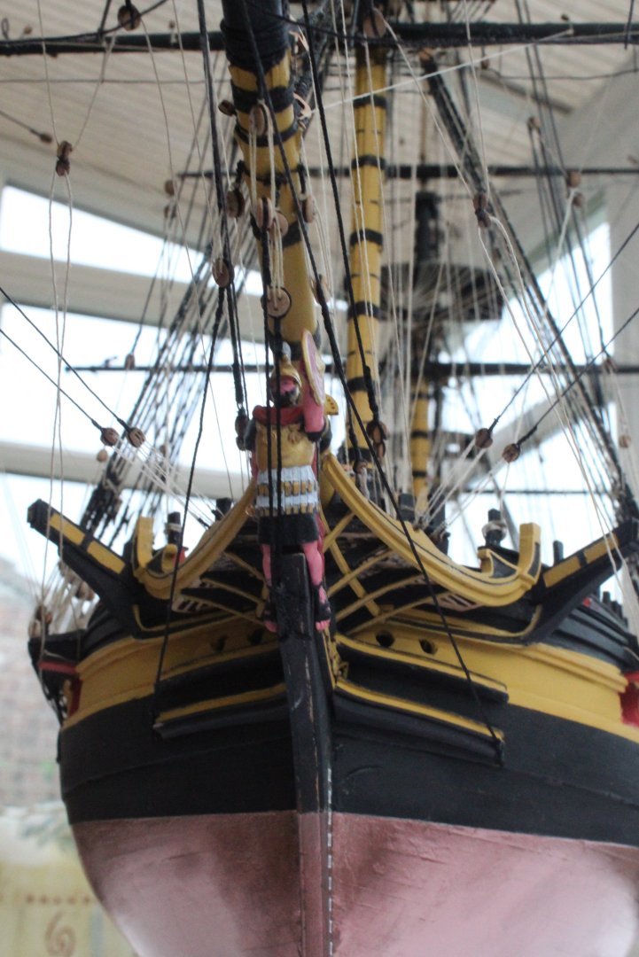
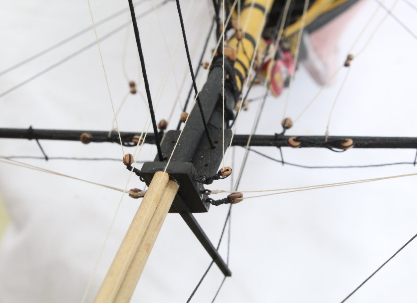
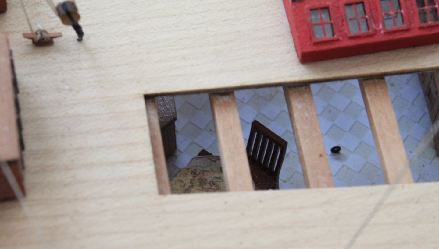
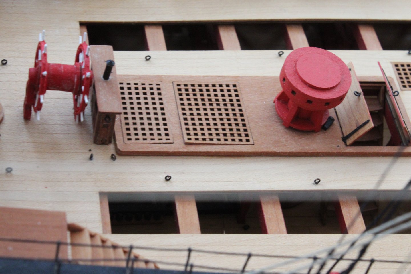
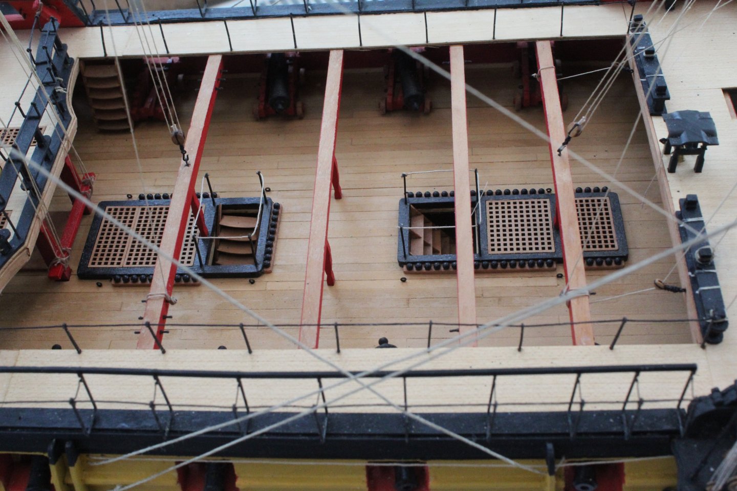
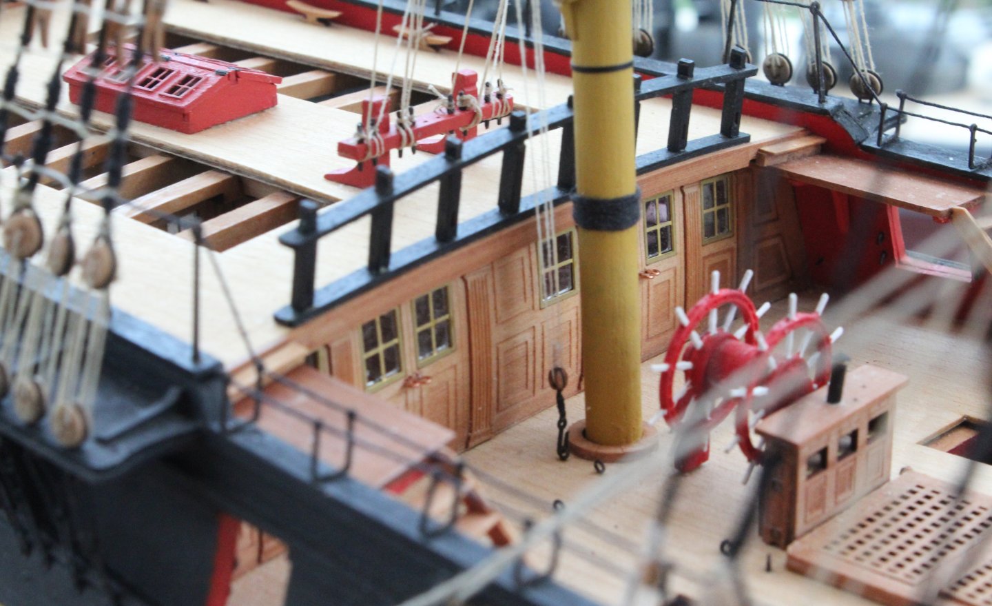
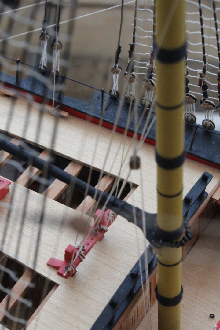
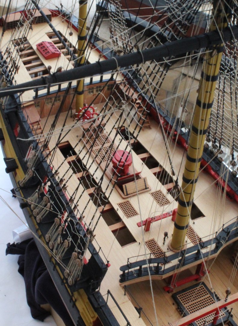
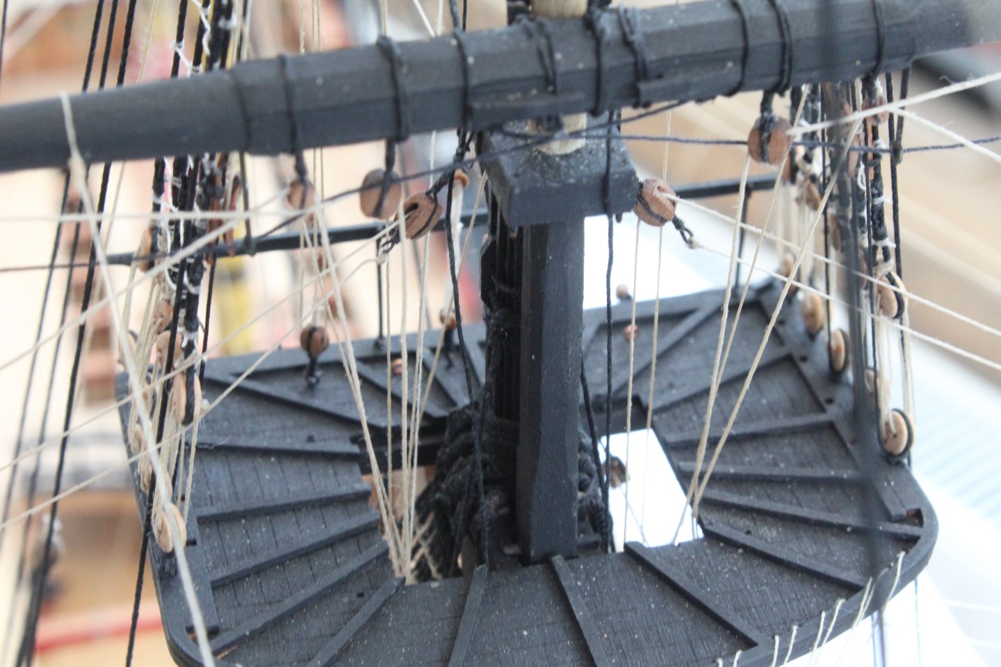
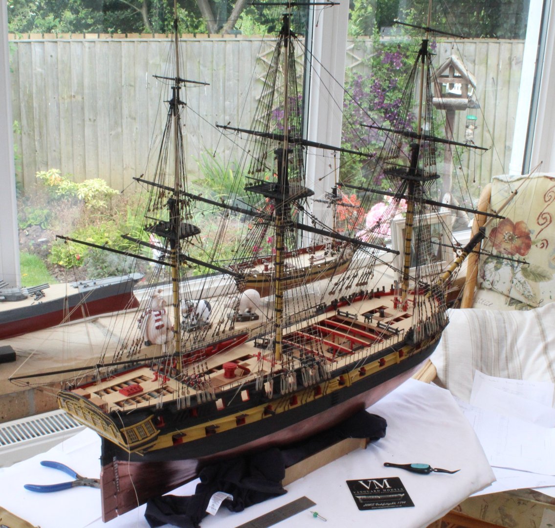
The End Is Near Over the last couple of days I have added the Main Course Bowlines and all the fore yard bowlines. This means I have now completed the rigging task. I still have a few little jobs to undertake before the build process is complete, which include: a) building and installing the 4 off anchors b) building and installing the 2 off lanterns c) building the perspex cradle d) adding 4 off knotted footropes to the bowsprit and spritsail e) adding the various cannons to the Indy f) Adding the stunsail booms. g) Populate the bitt racks with belaying pins, in the unused positions. I am not planning to build or include the small boats as I like an uncluttered gundeck. I have really enjoyed building this model. It has, at times, been challenging and I have made a few mistakes along the way but nothing major. It has really tested my rigging skills which I believe as improved immeasurably as a result. My next project will be the HM Brig Adder as I really like the look of this model which I am looking forward to starting in the next couple of weeks, once I have ordered and received the kit. Once the build is complete I will try to take a selection of better photos, using my white background to removed the unwanted background. In the meantime I have taken a few photos of the Indy in the shipyard which are included with this post. One of the nice aspect of this model is there is a view into the view Captains cabin, which includes a nice selection of furniture. Now a few photos of the deck features. There is such a great amount of detail provided with this fantastic kit. To complete this post I have added a few photos of the rigging. It is difficult to take decent rigging photos but hopefully these pictures will give the reader a taste of the complexities.


- 587 replies
-
- 15
-
-
-
- Indefatigable
- Vanguard Models
- (and 1 more)
-
I was feeling so pleased with my work and especially after I had fed the lines through the blocks under the platform. I might have uttered the odd expletive when I discovered my error. Thankfully it was a fairly straightforward and quick job to remove the offending line and rerig.
- 587 replies
-
- 1
-
-
- Indefatigable
- Vanguard Models
- (and 1 more)
-
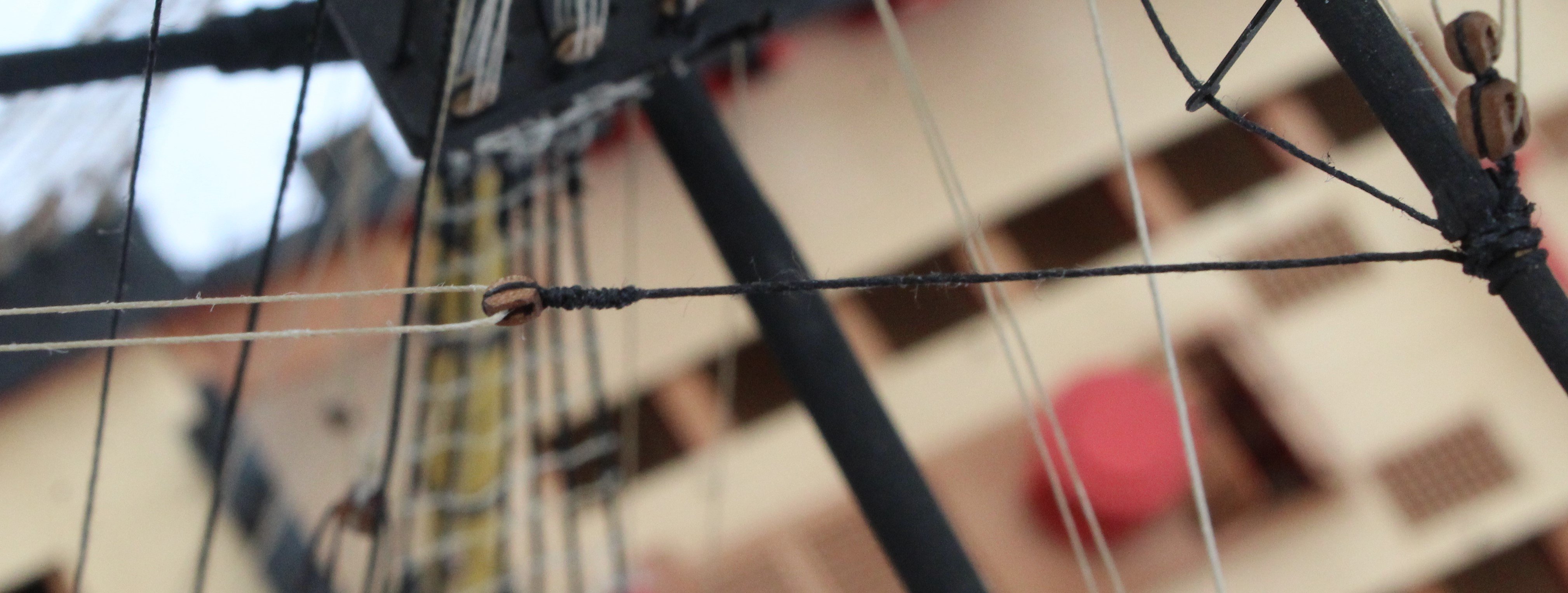
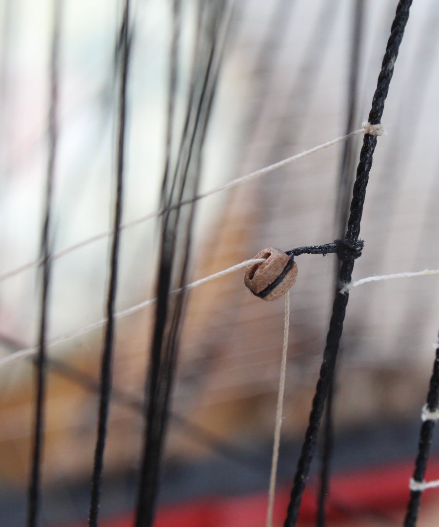
Rigging Foreyards I am now on the home straight and think I will complete the Indy before the end of the month. I think I only need to install the following rigging (but I will recheck all the rigging plan sheets to be certain): a) main yard course bowlines b) fore yard course bowlines c) fore topsail yard bowlines d) fore topgallant yard bowlines All the other outstanding foreyard rigging has now been run in and belayed except for the braces (fore, topsail and topgallant yards) which still requires to be belayed. The first photo in this post shows the current build status. The next few photos show the process I used when rigging the foreyard bunt and leech lines. I started by running in all the bunt and leech lines. After the bunt and leech lines were run in I added the toggles so the lines were held firm next to the foreyard blocks, as shown in the photo below. I did make a light error with the port side, which I only noticed after I had belayed the rigging. I ended up redoing the outer bunt line and it now looks much better. The most arduous task with this rigging process was to run the bunt and leech lines through the 2 pairs of blocks located under the foreyard platform. The next photo indicates the chaos that can exist after the foreyard bowlines have been run in but not belayed. It looks so much better after all the lines were belayed. Once I was happy with how they all looked the excess thread was trimmed.


- 587 replies
-
- 6
-
-
- Indefatigable
- Vanguard Models
- (and 1 more)
-
Looks great. I am planning to build this model next.
- 66 replies
-
- 3
-
-
- Adder
- Vanguard Models
- (and 1 more)
-
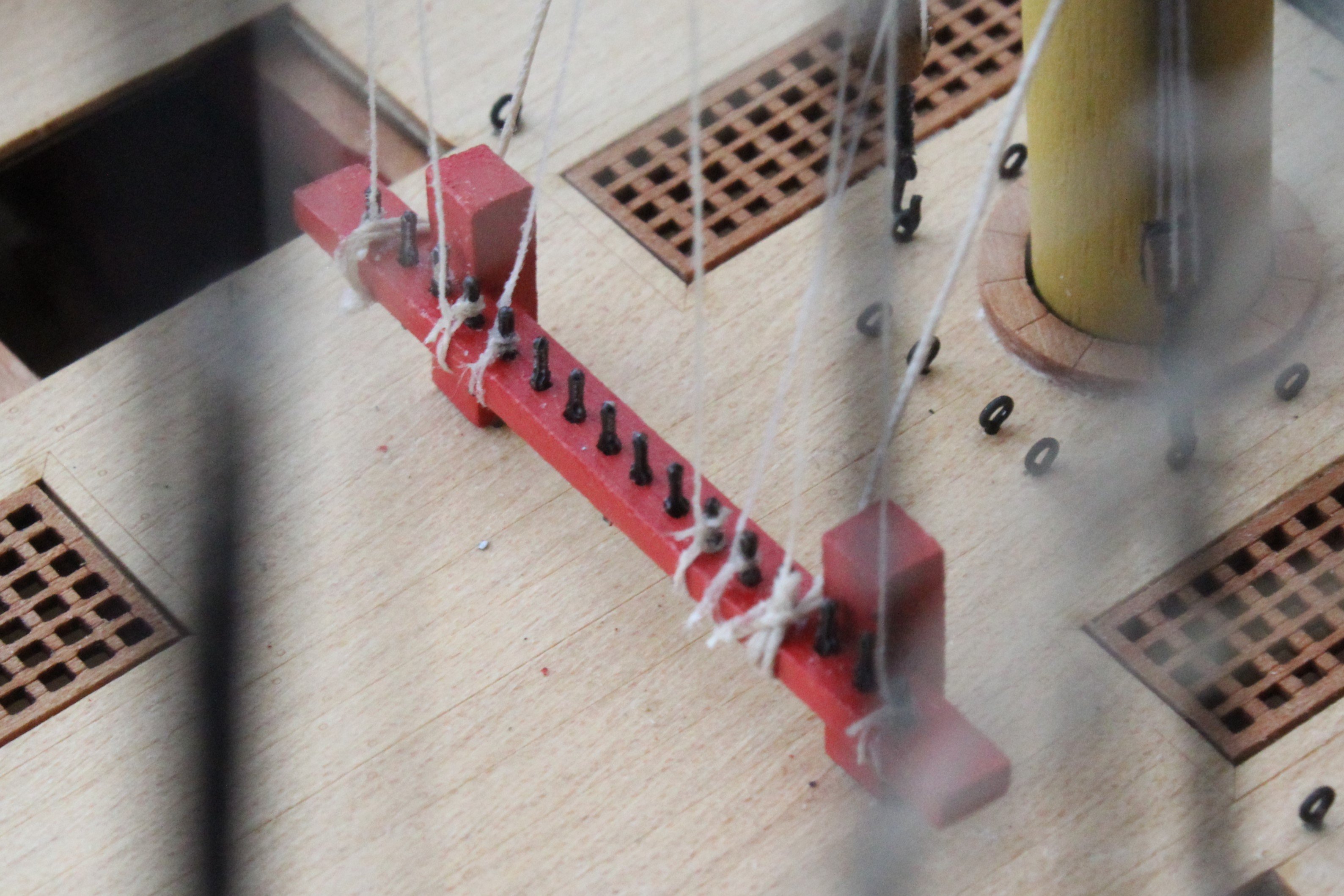
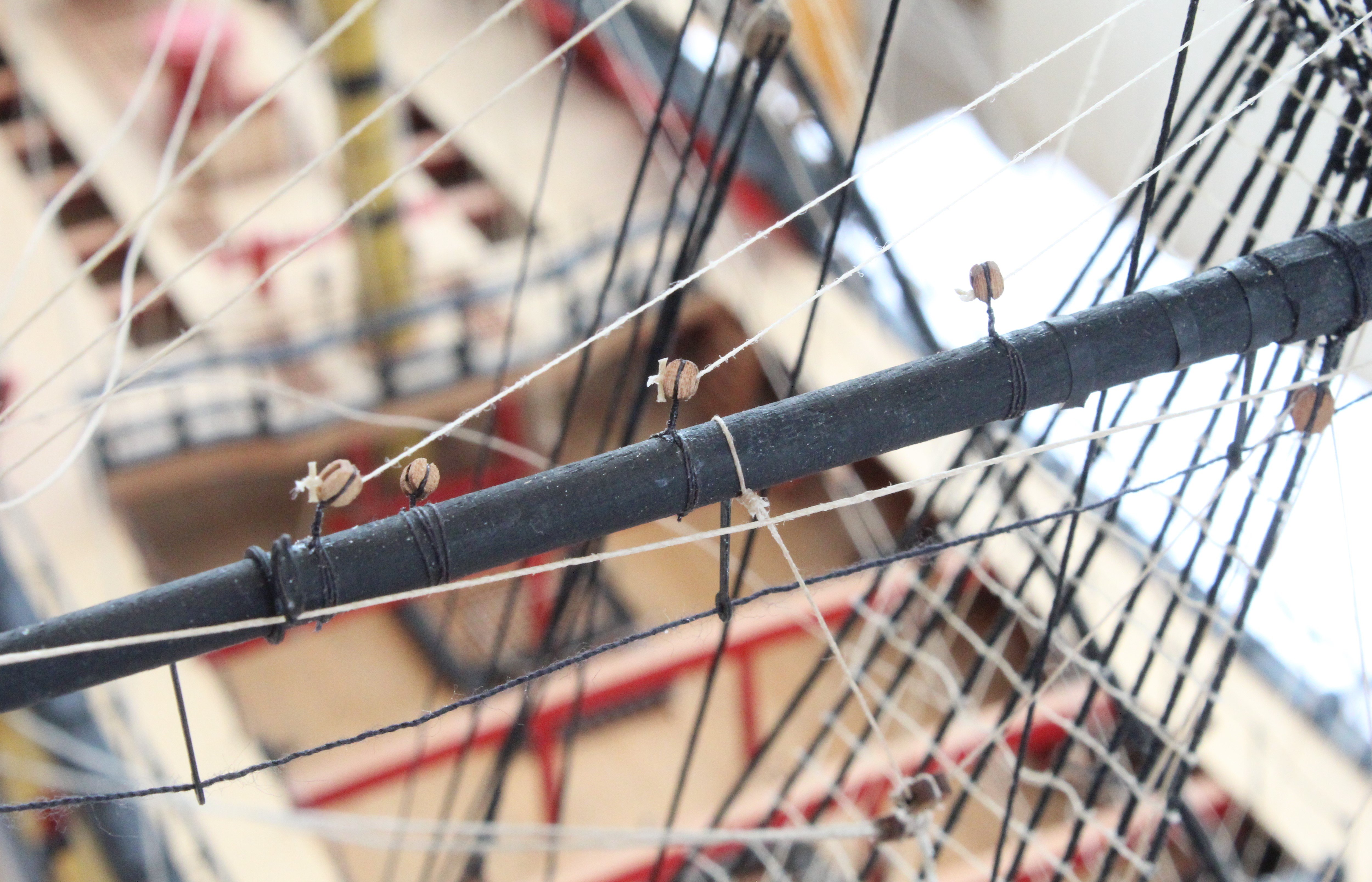
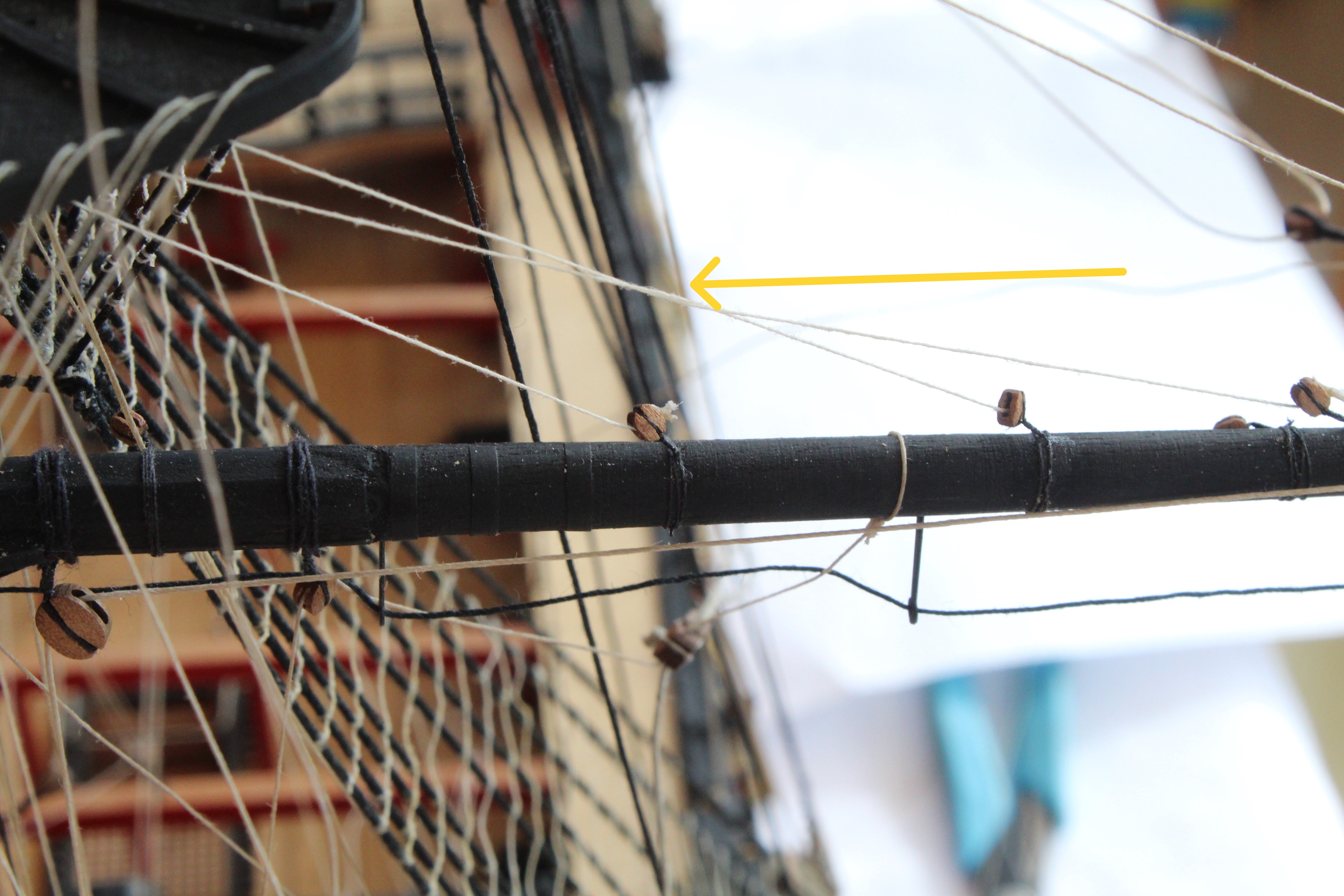
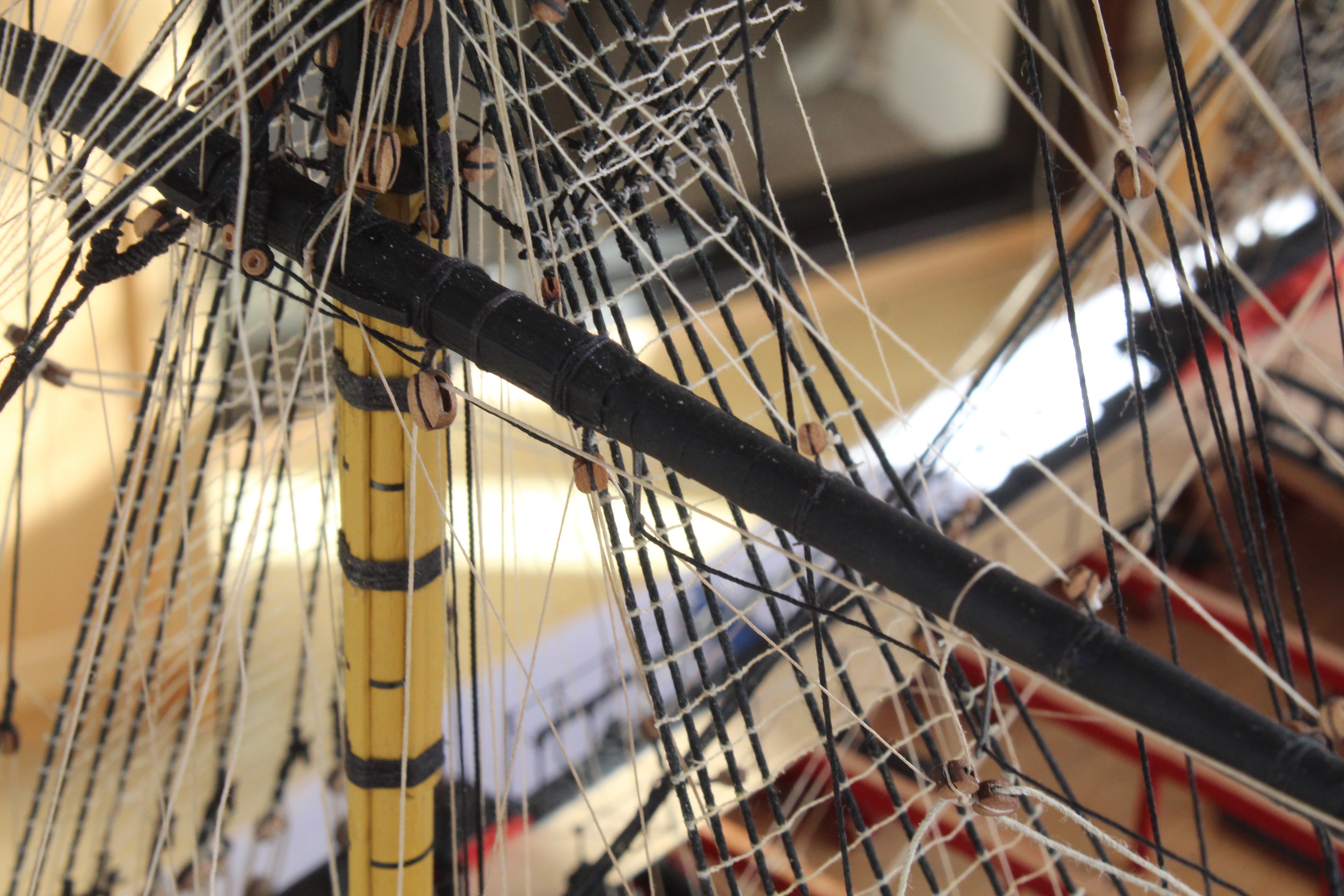
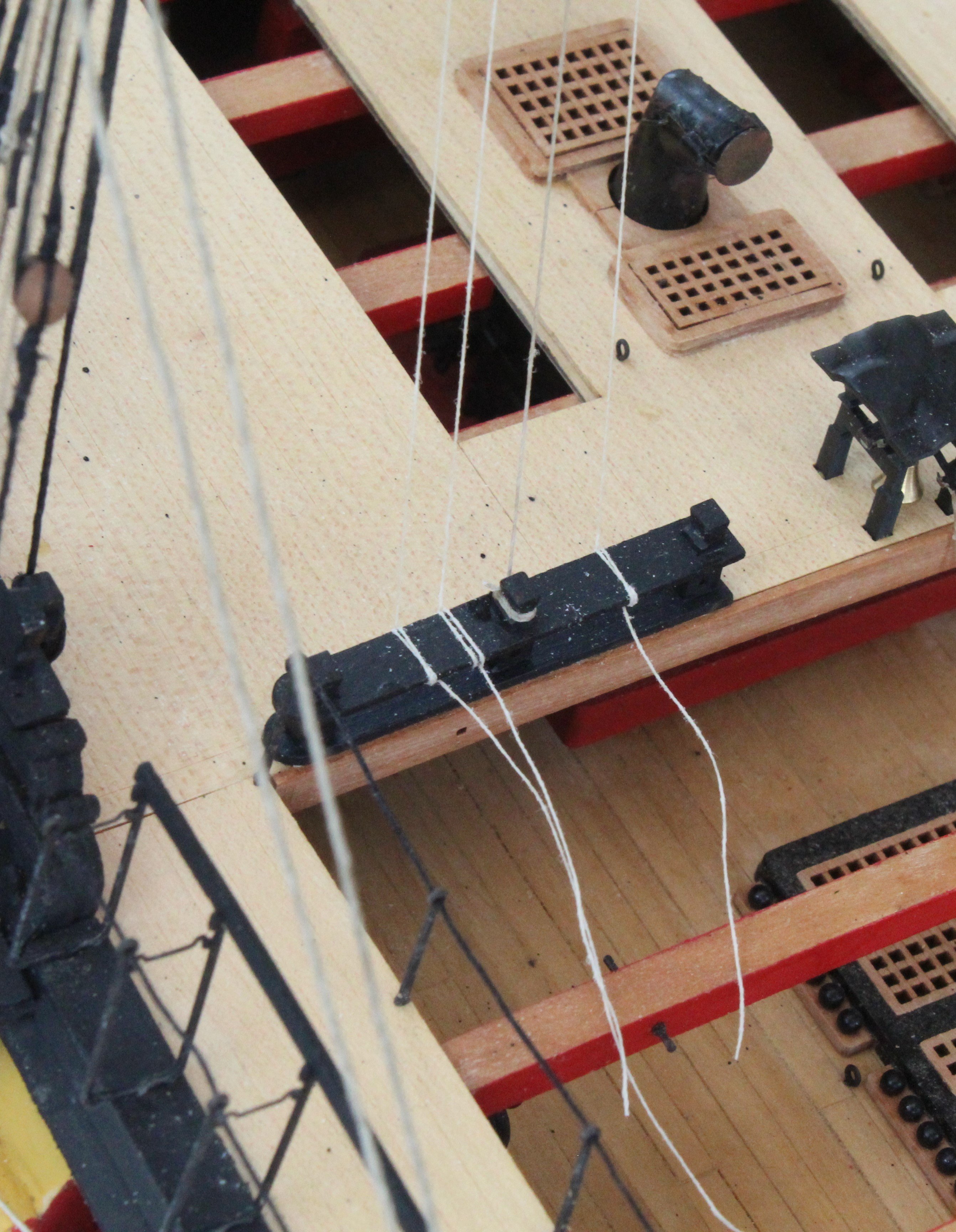
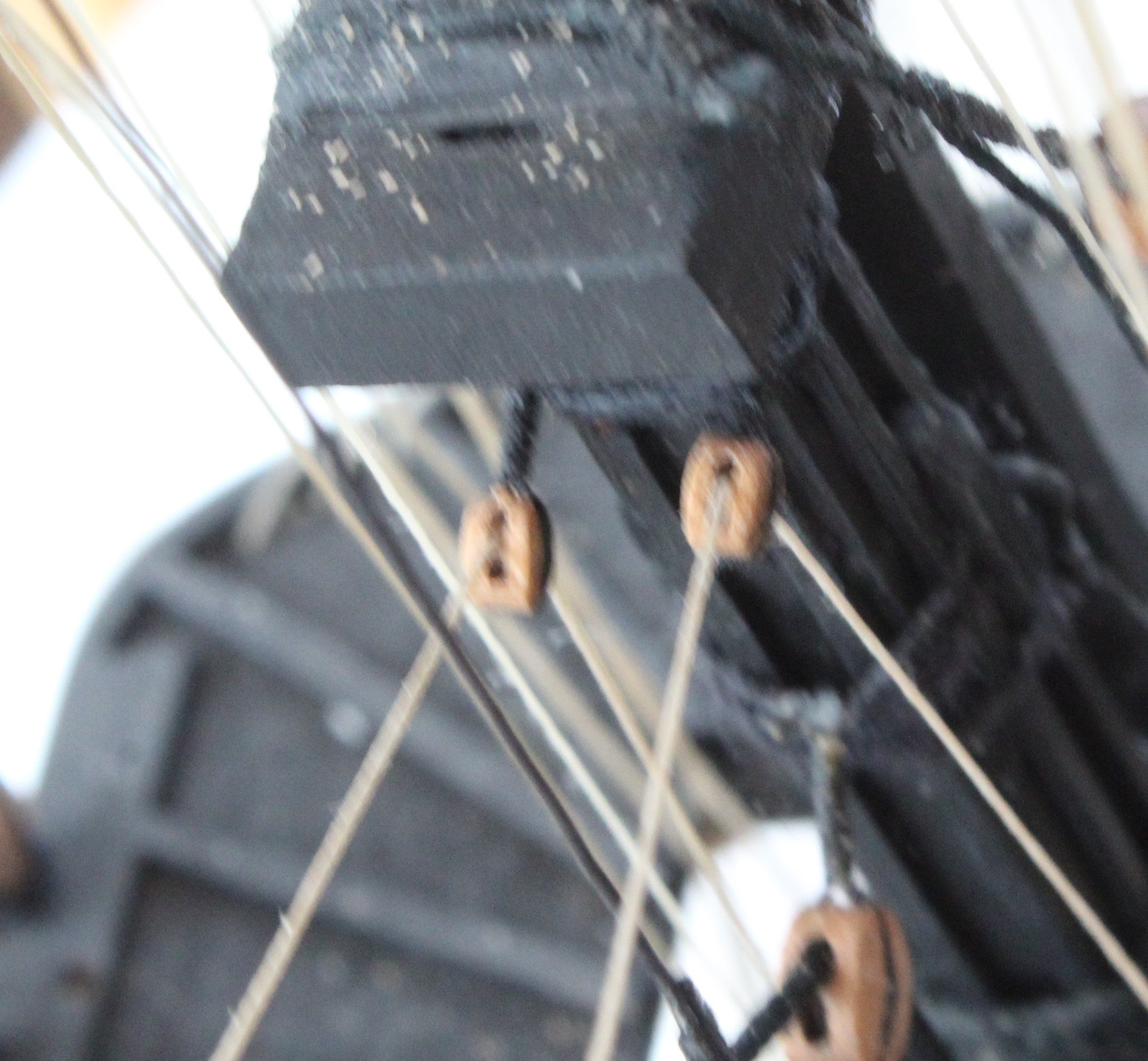
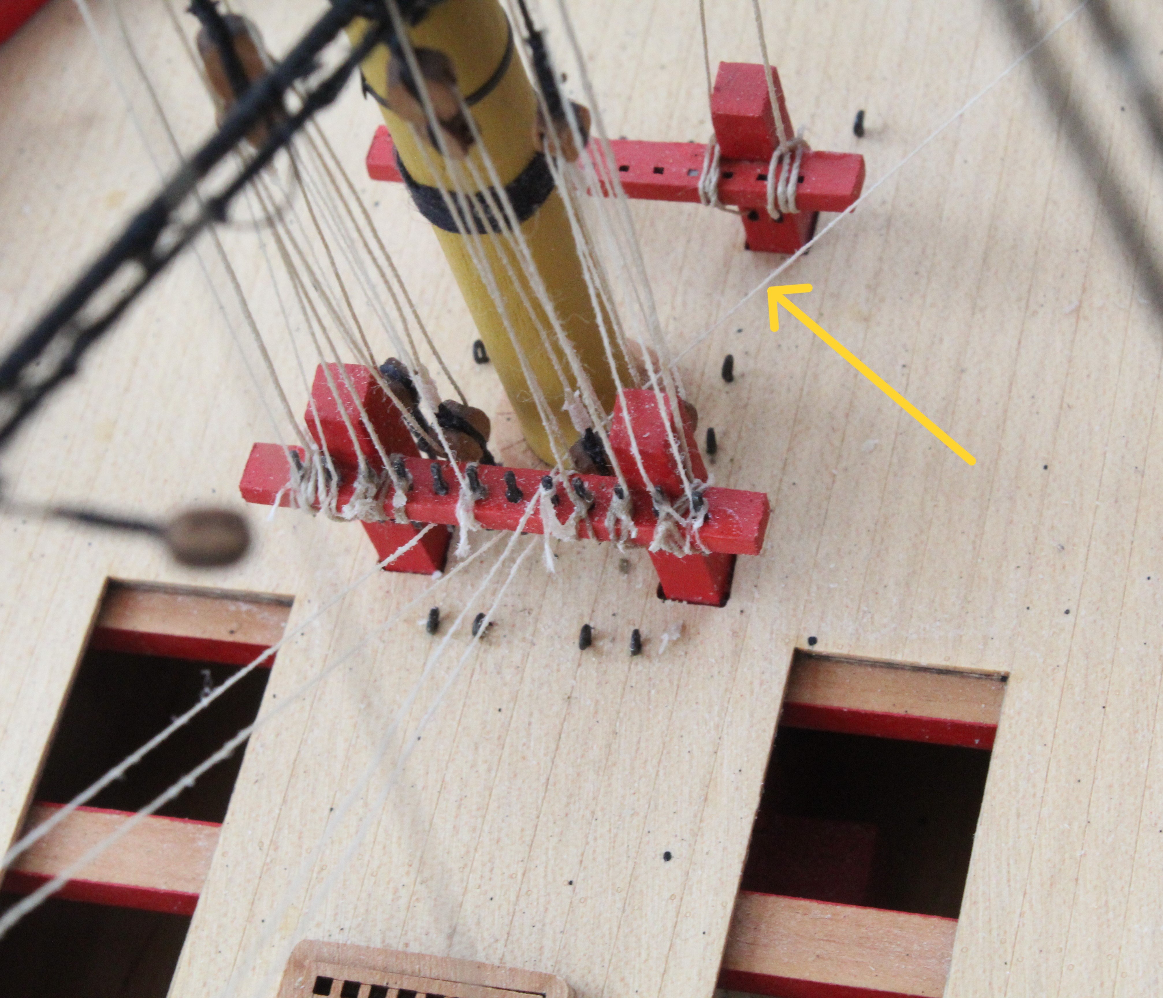
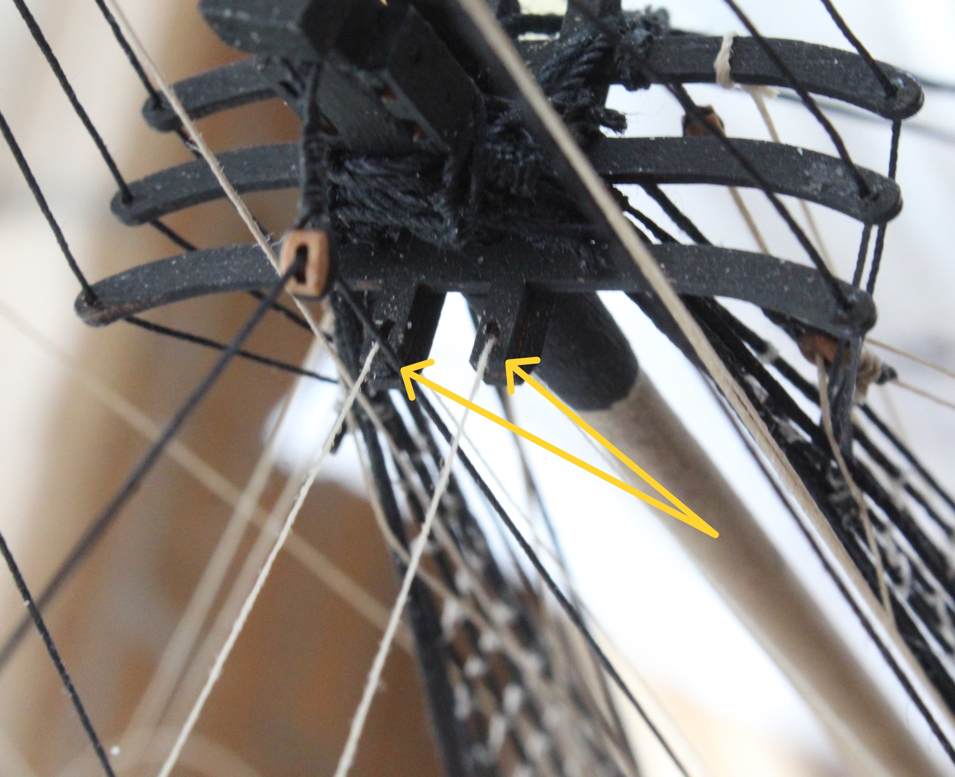
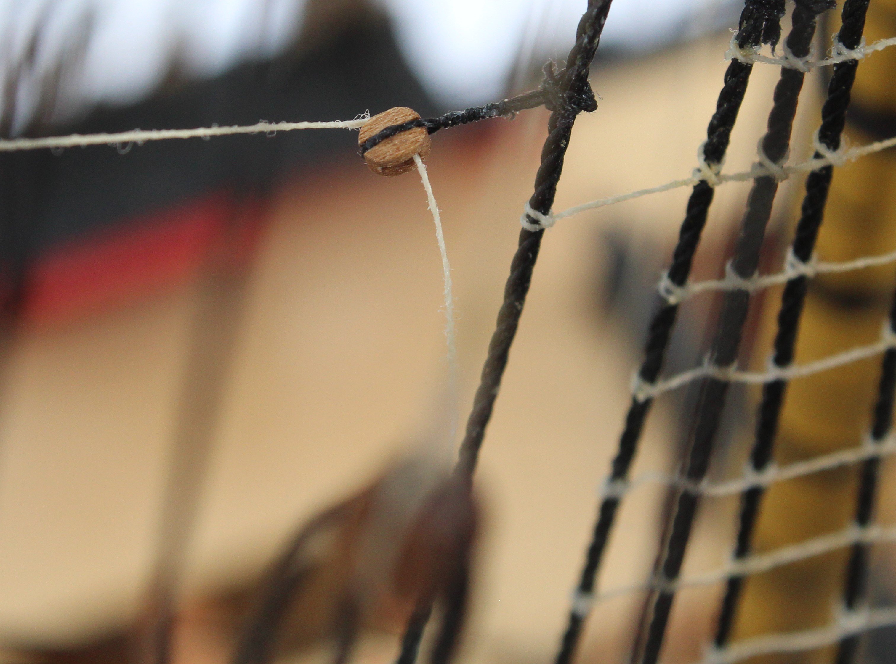
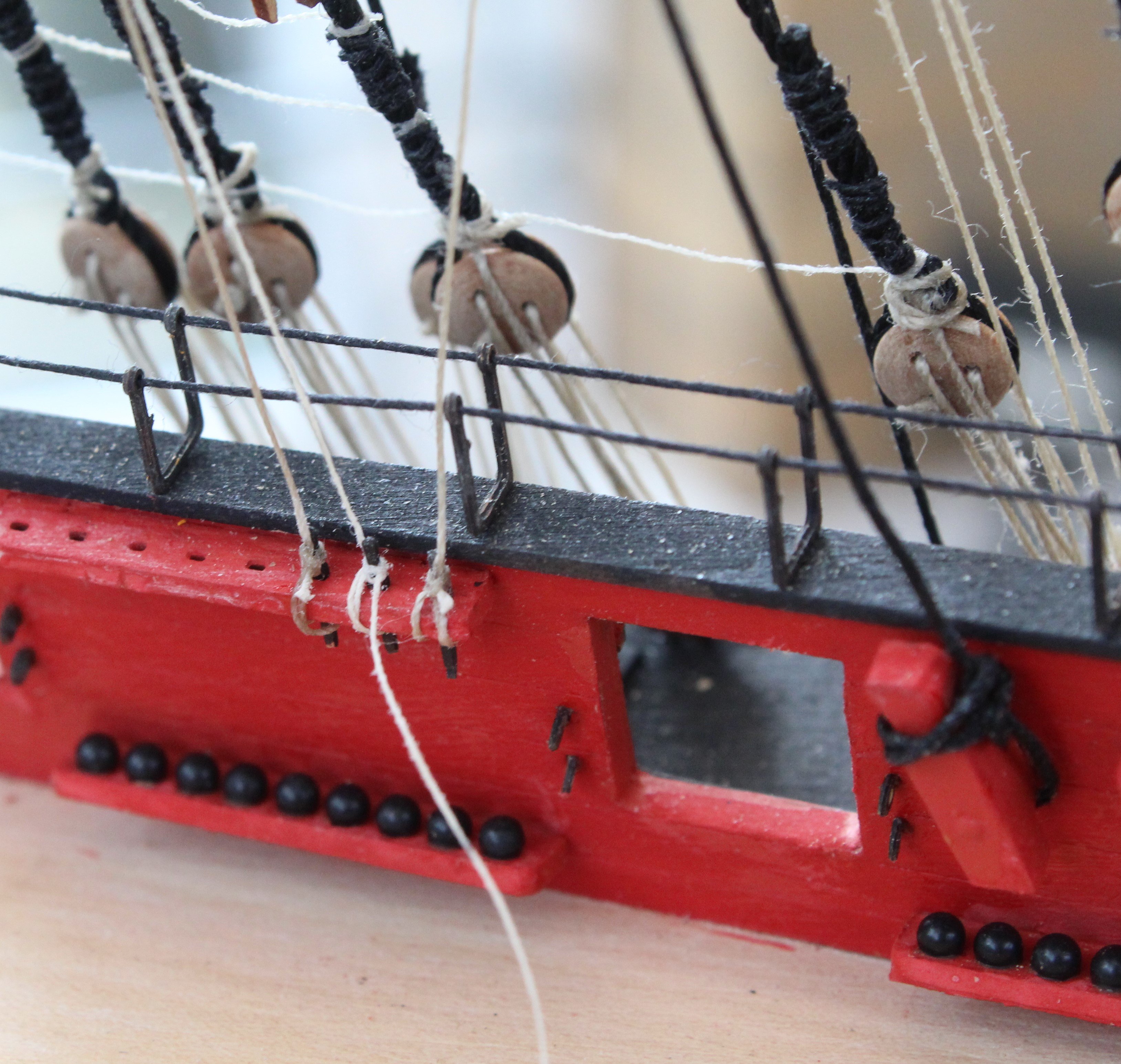
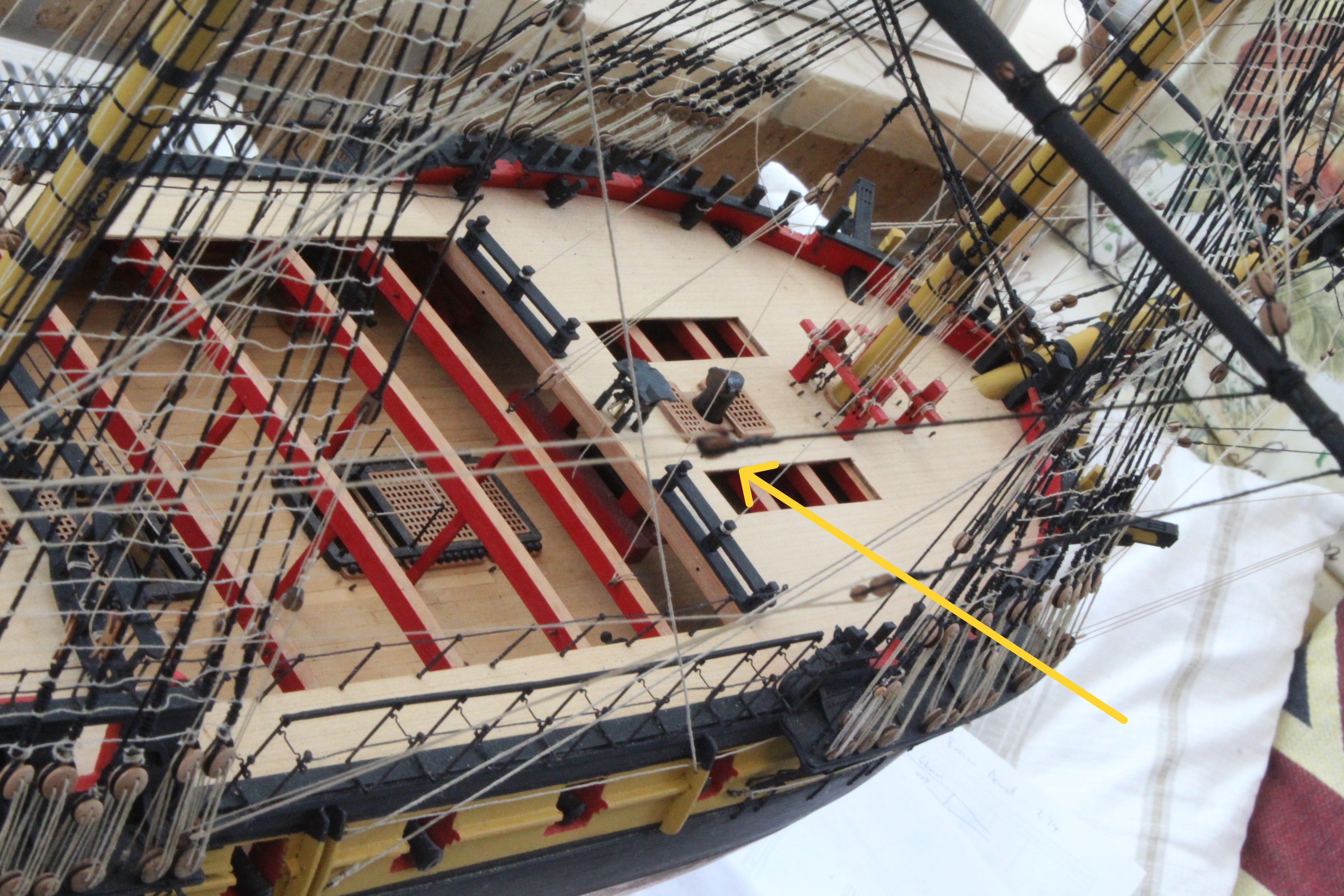
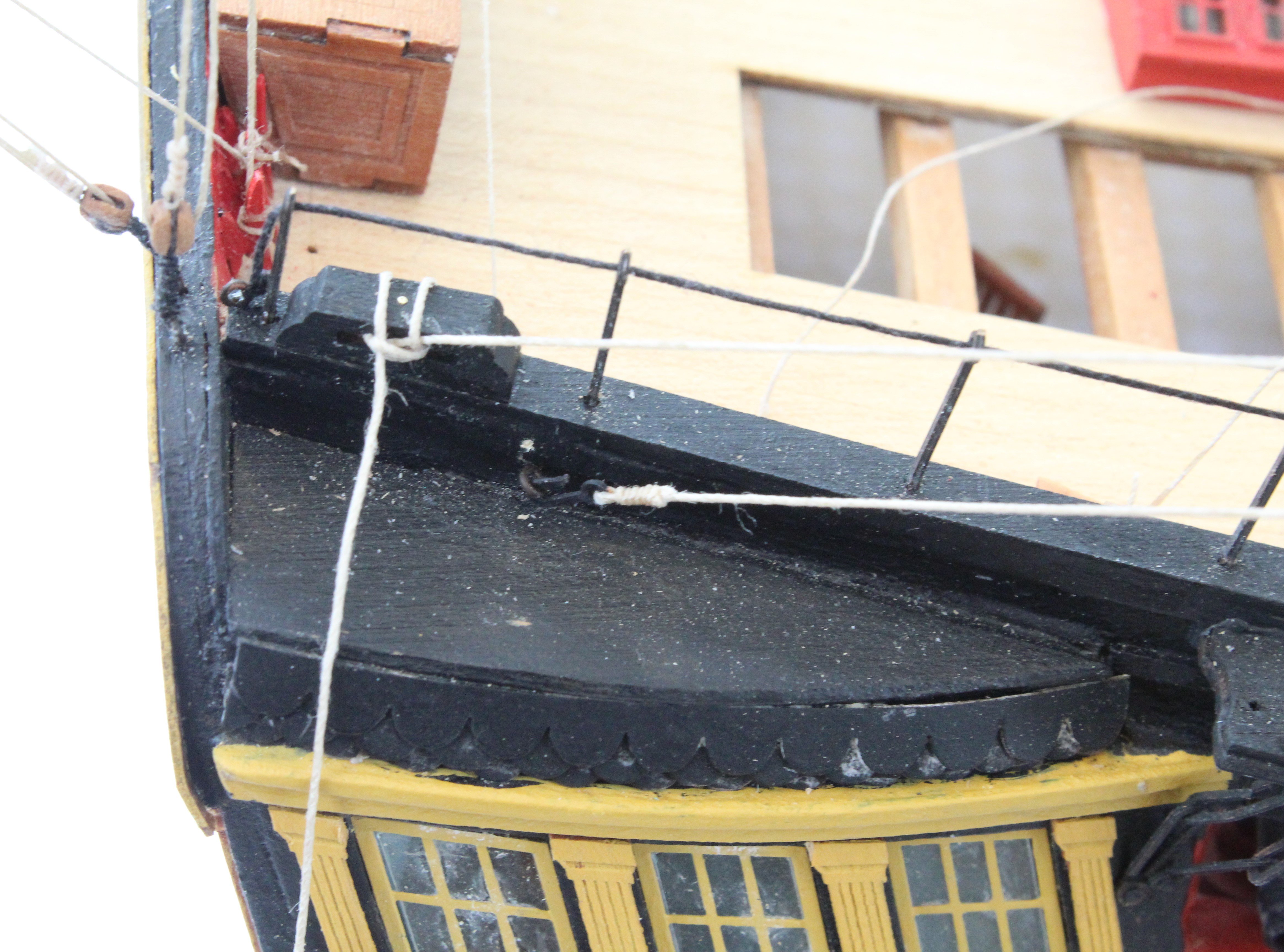
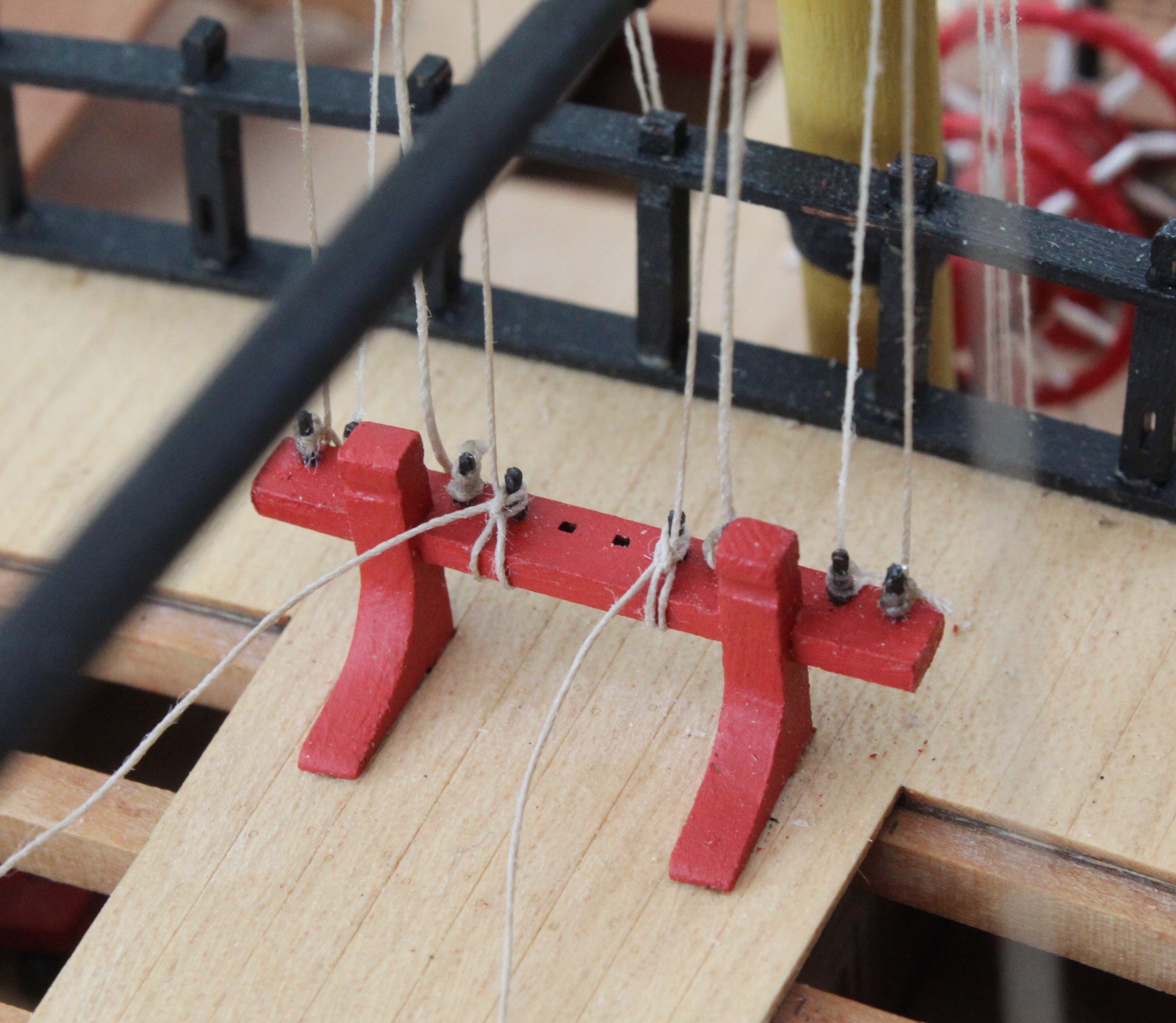
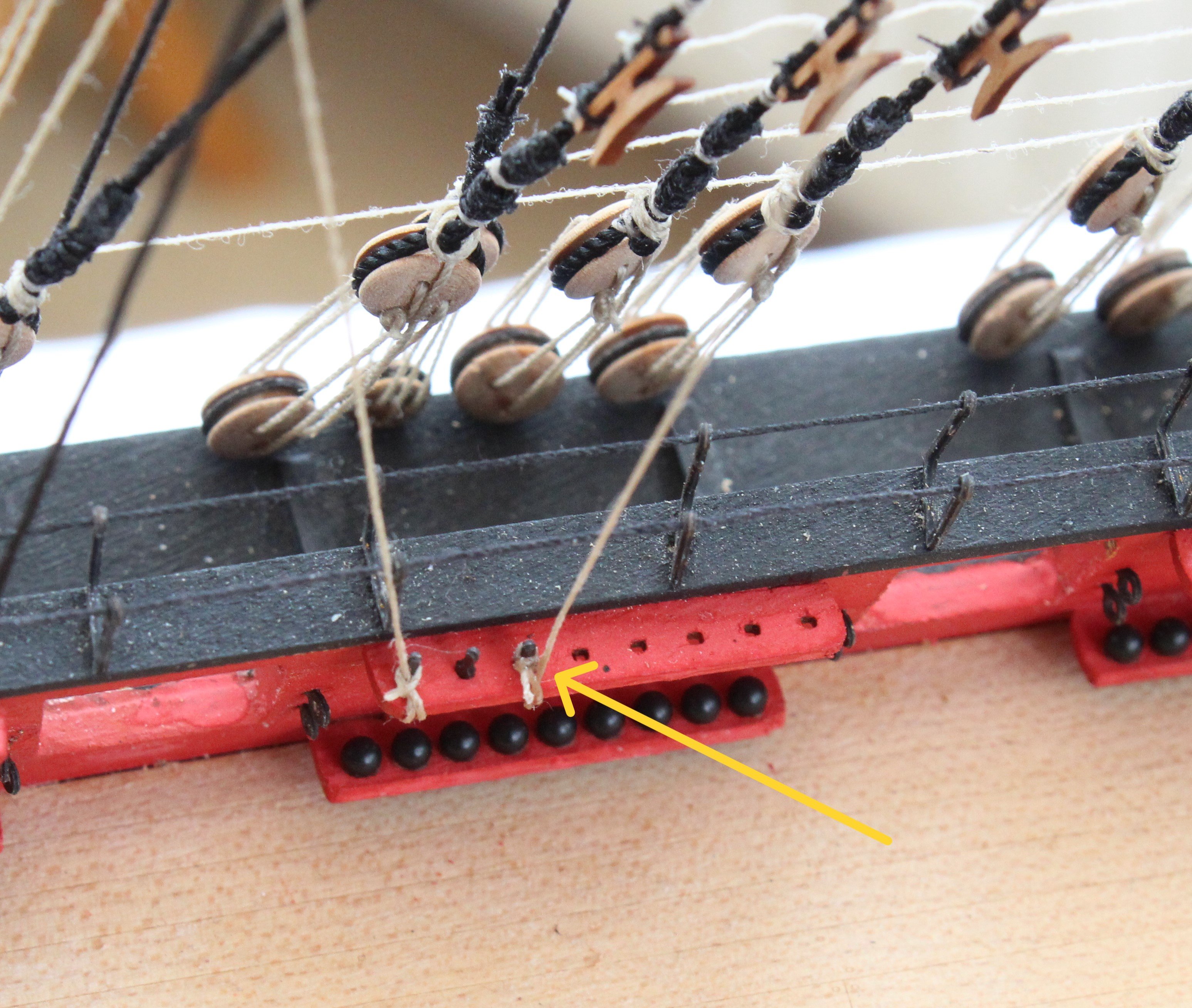
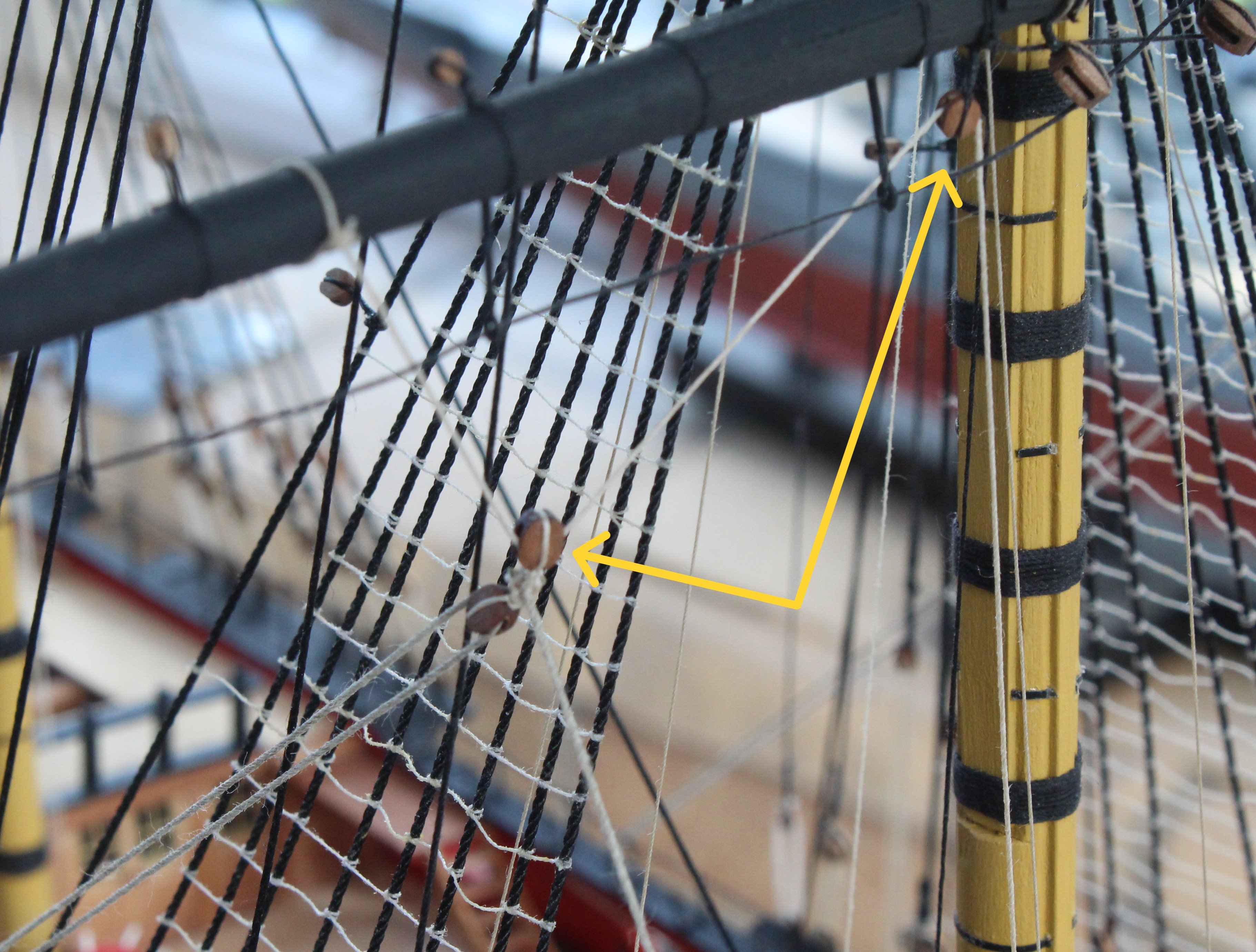
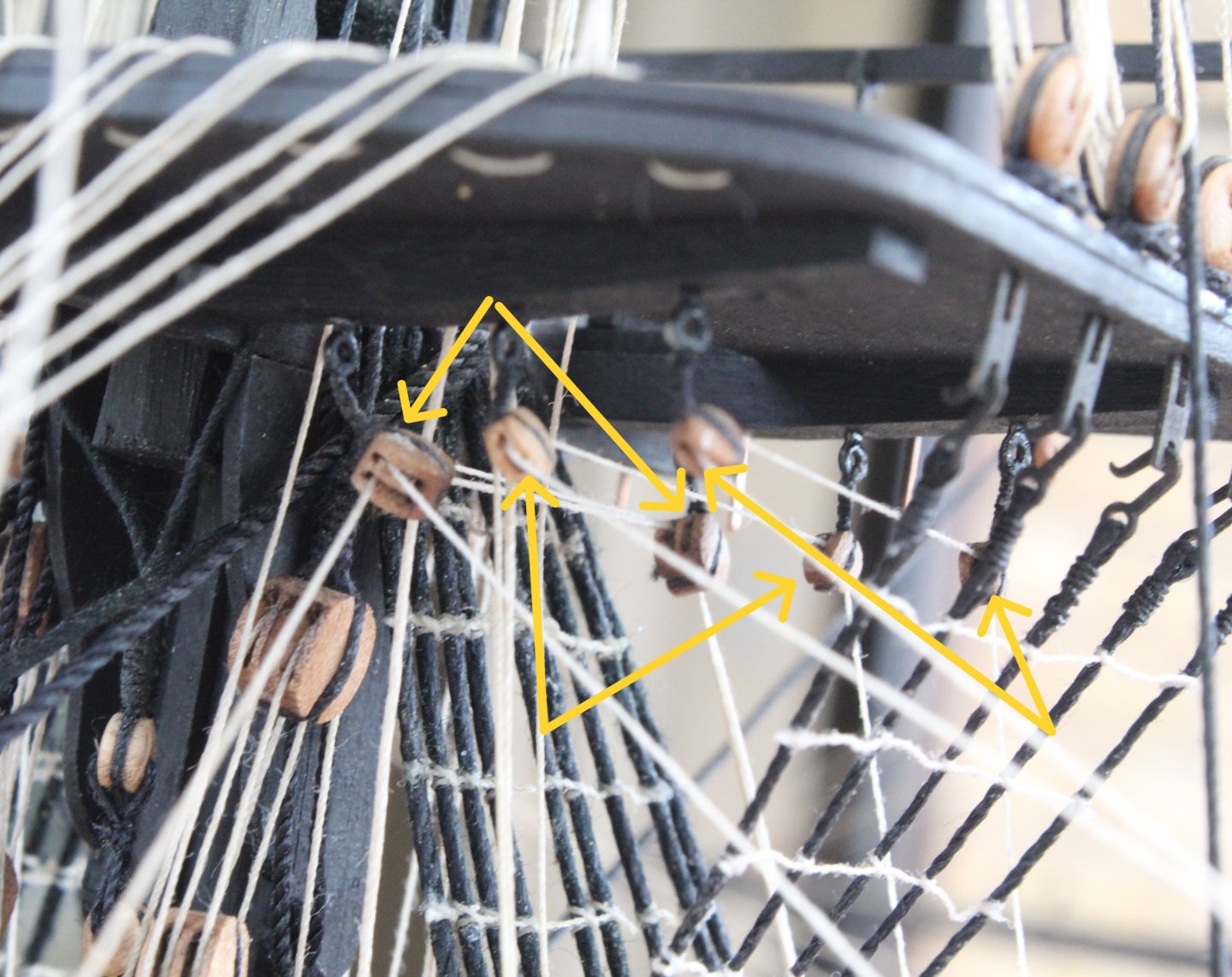
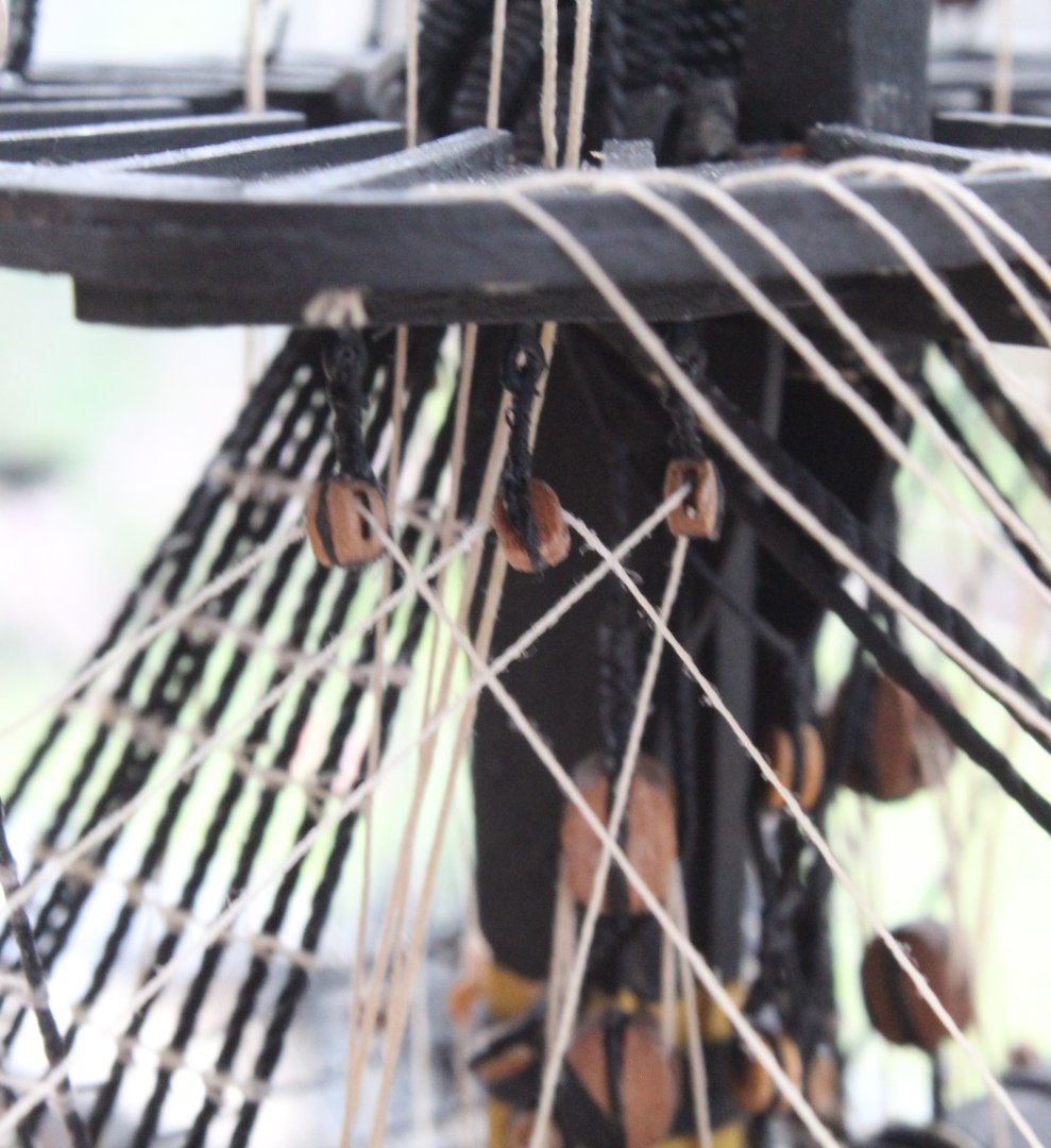
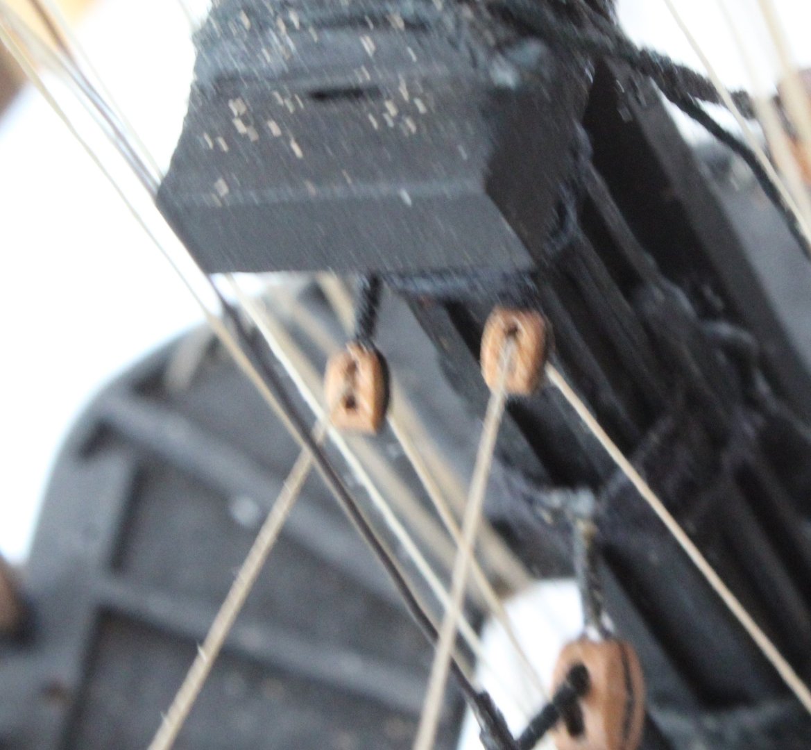
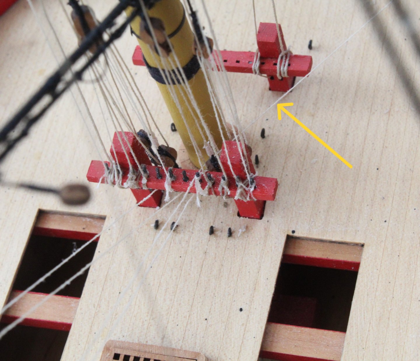
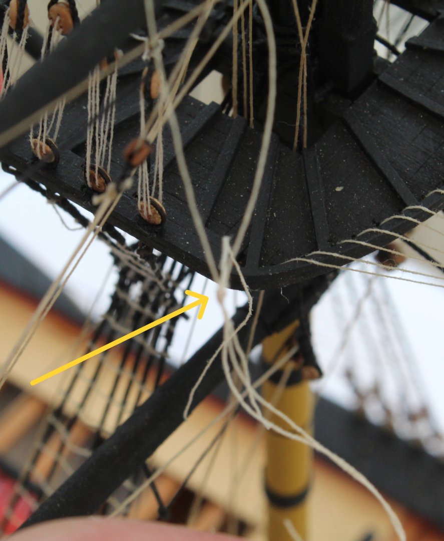
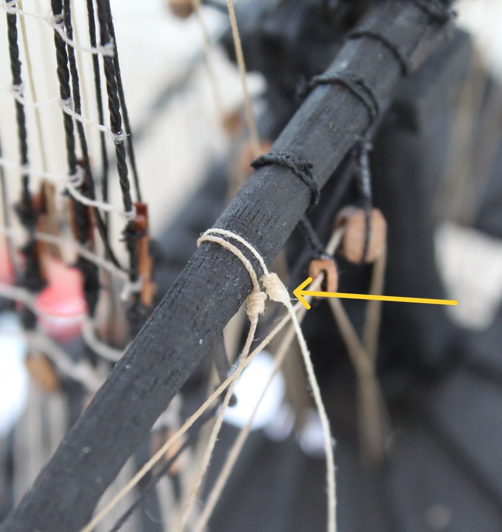
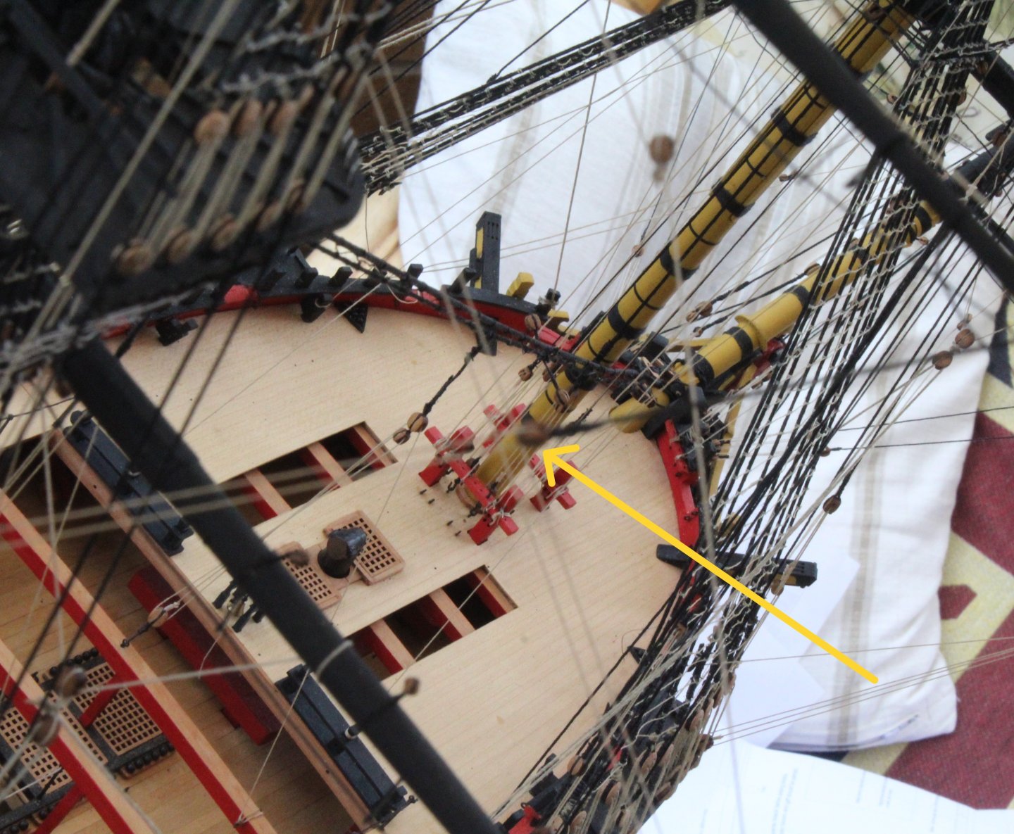
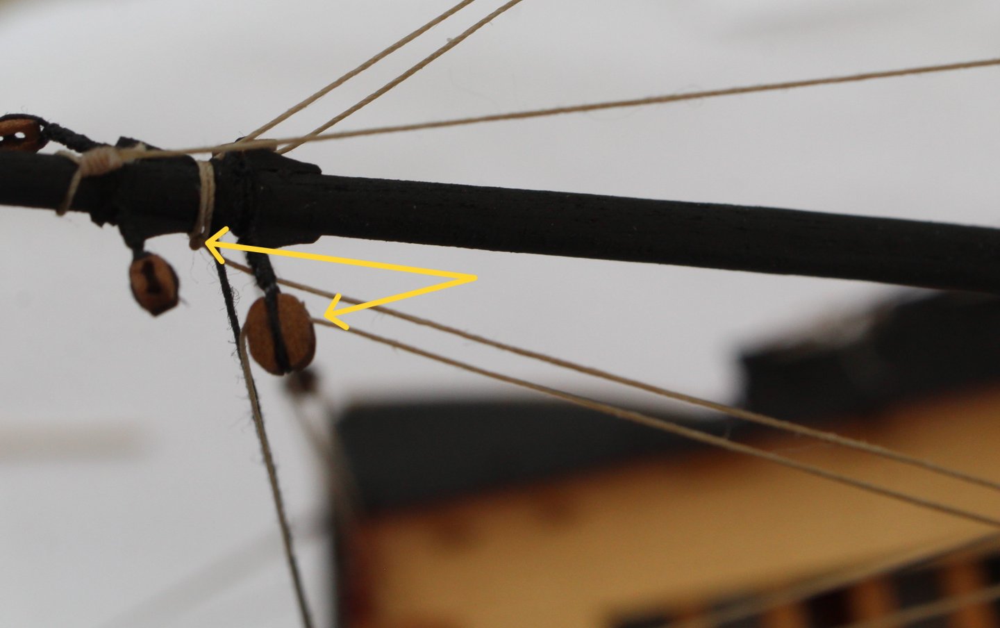
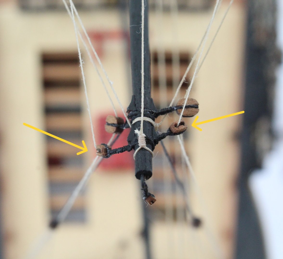
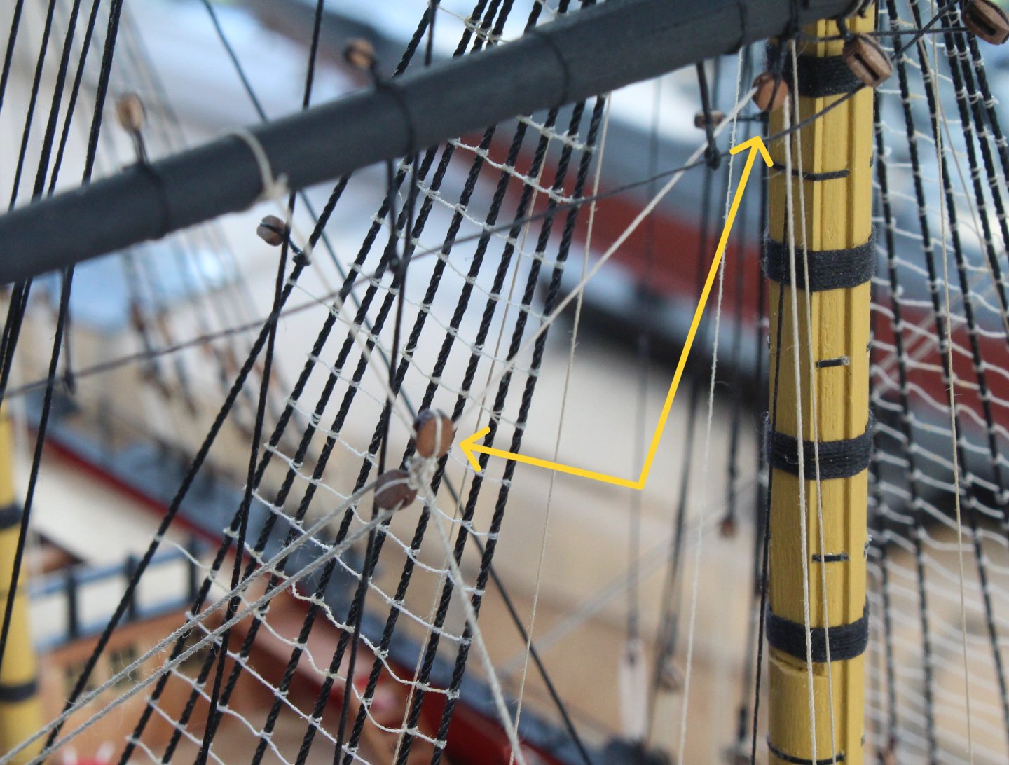
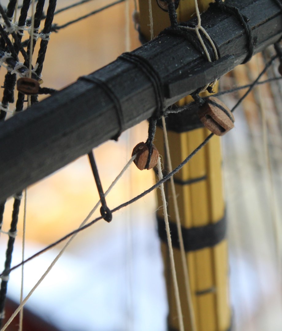
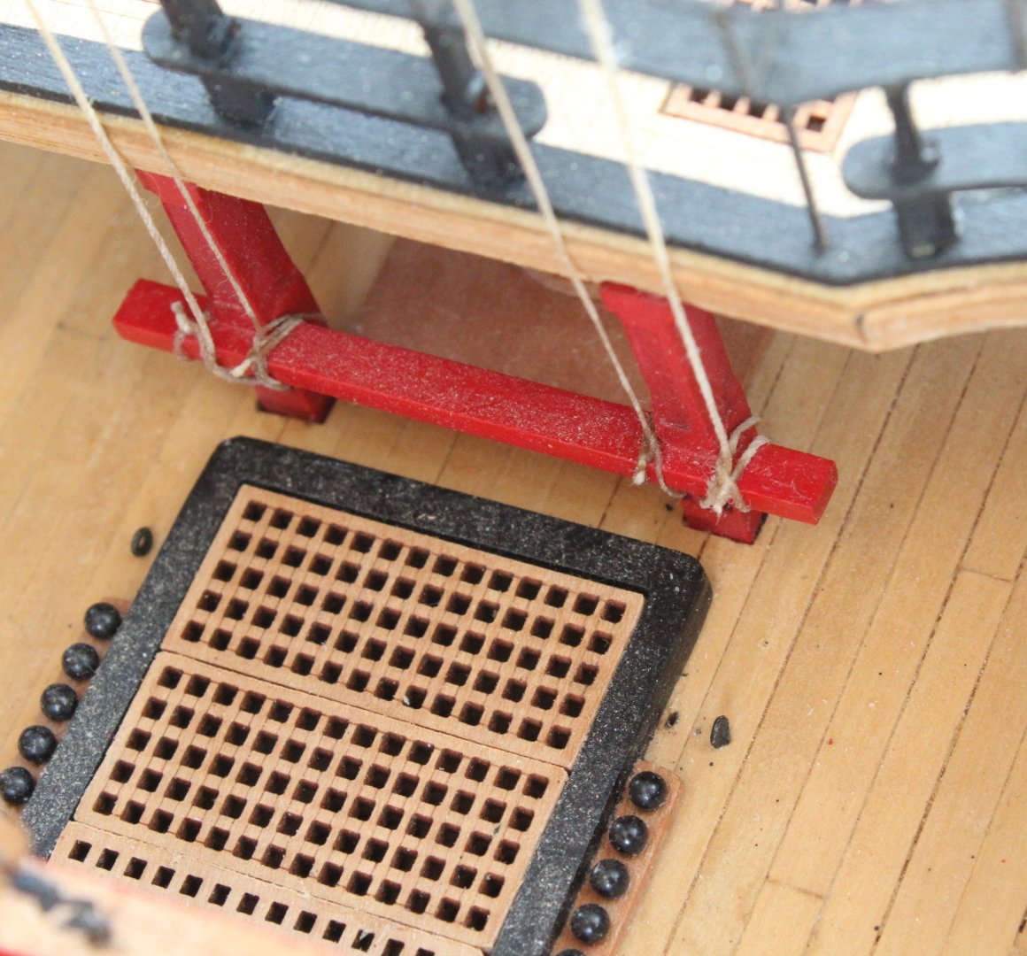
Main Mast Bunt. Leach and Bowlines Before moving on to installing the braces for the 3 fore mast yards I decided it would be better to add the main mast bunt, leach and bowlines. I felt this was a good idea as access, for belaying, would be more restricted if the braces (especially for the foreyard) had been rigged. I opted to start with fitting the main topsail and topgallant yard bowlines. They were installed without any issues. I still have the main course bowline to add which will be done later as I think it run to the belaying point (cleats on forecastle bulwarks) will hinder the installation of the bunt and leach lines. The first (out of focus) photo shows the blocks used to take the topsail yard bowline down to the deck level The next photo shows how the main topgallant yard bowlines are taken down to the deck level, via the upper foremast platform. The bunt and leach lines are fed through blocks on the main yard and are held in place with toggles, as can be seen in the next photo. These lines were fed through blocks located under the main platform, as shown in the next photo. The bunt line (two per side) are belayed to the aft foremast bitt rack, via a double block arrangement. The final photo of this post shows the aft foremast bitt rack where the bowline and bunt lines have been belayed. The yellow arrow indicates the final bunt line that has not been belayed, noting I did belayed this after taking the photo.

- 587 replies
-
- 7
-
-
- Indefatigable
- Vanguard Models
- (and 1 more)
-
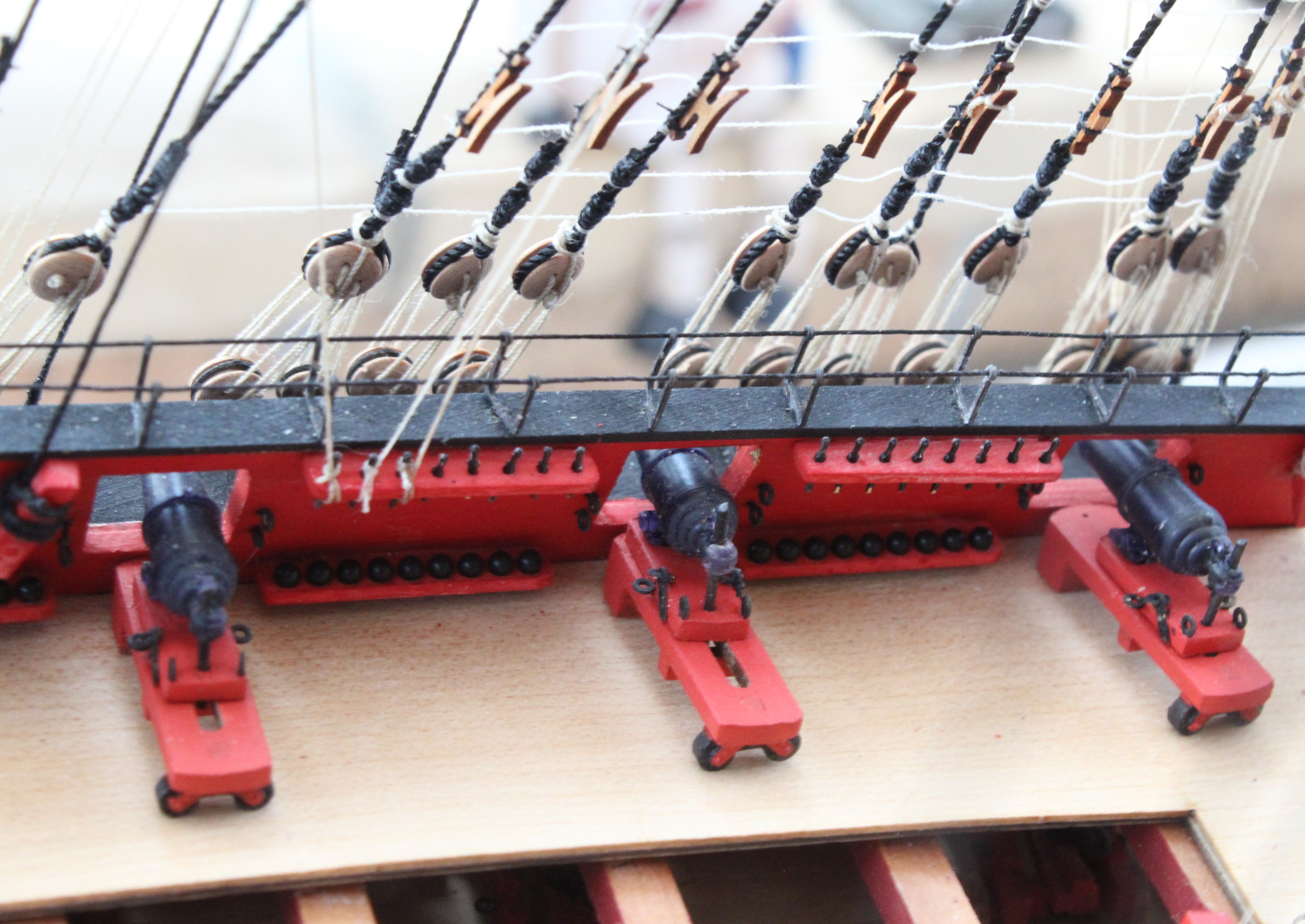
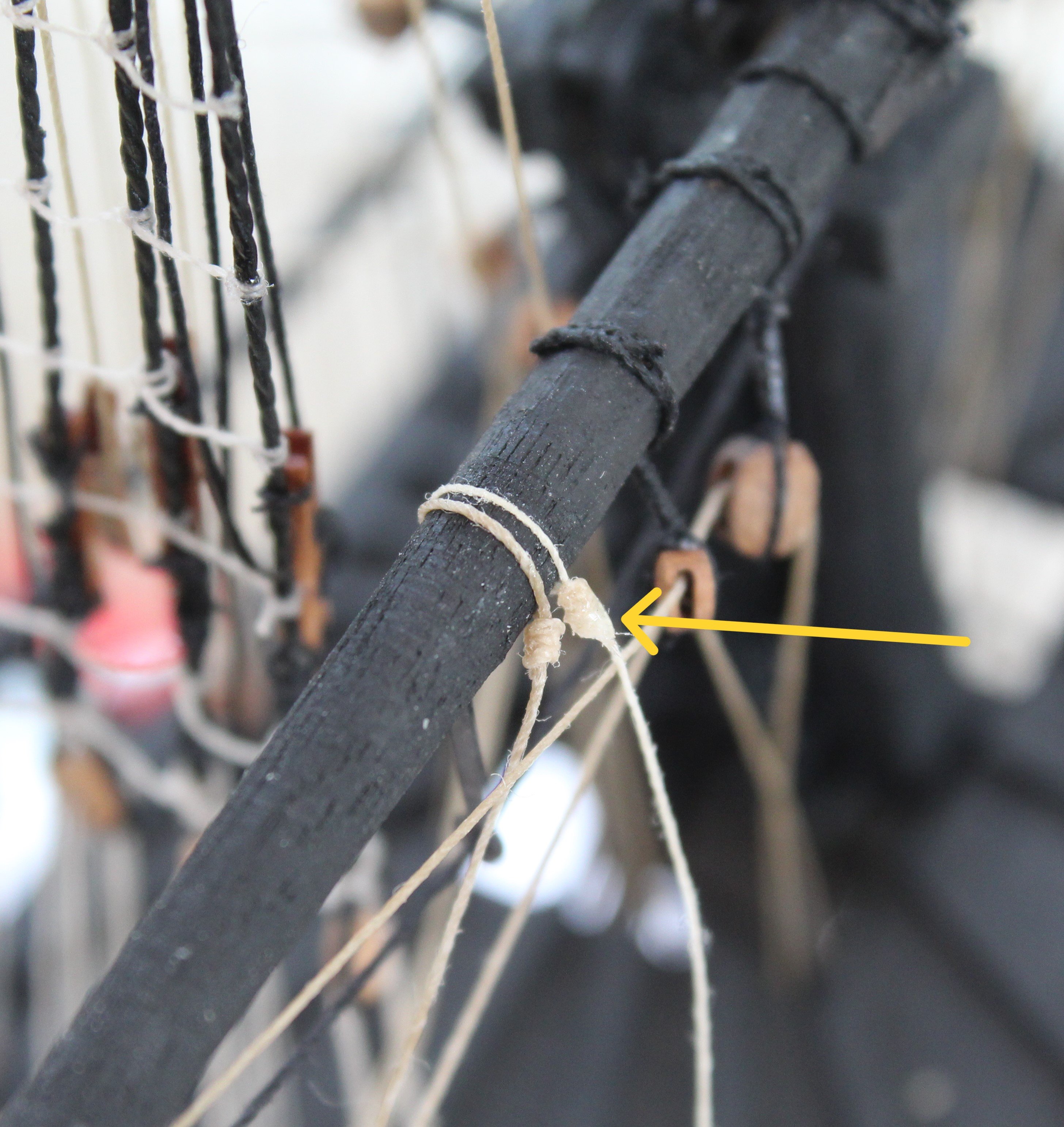
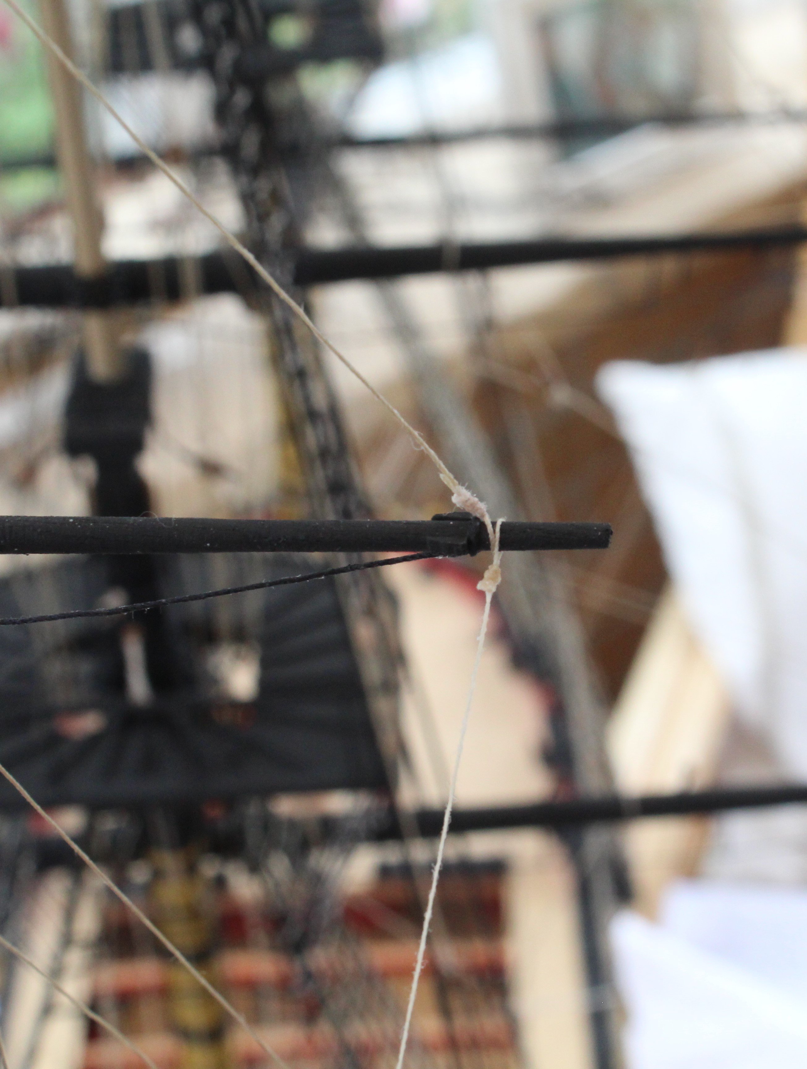
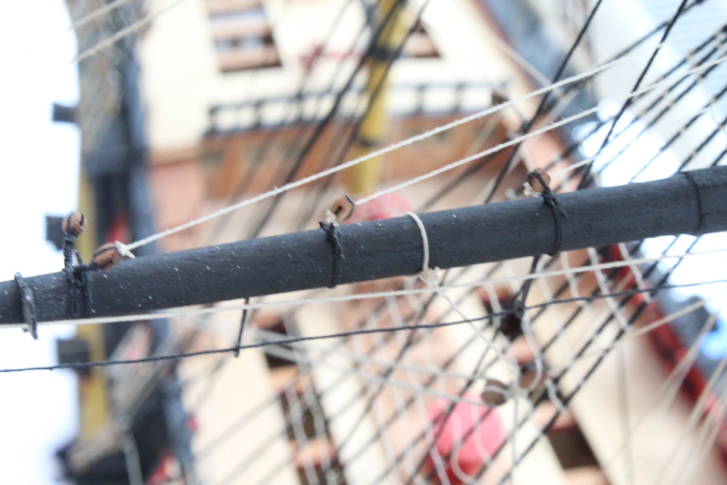
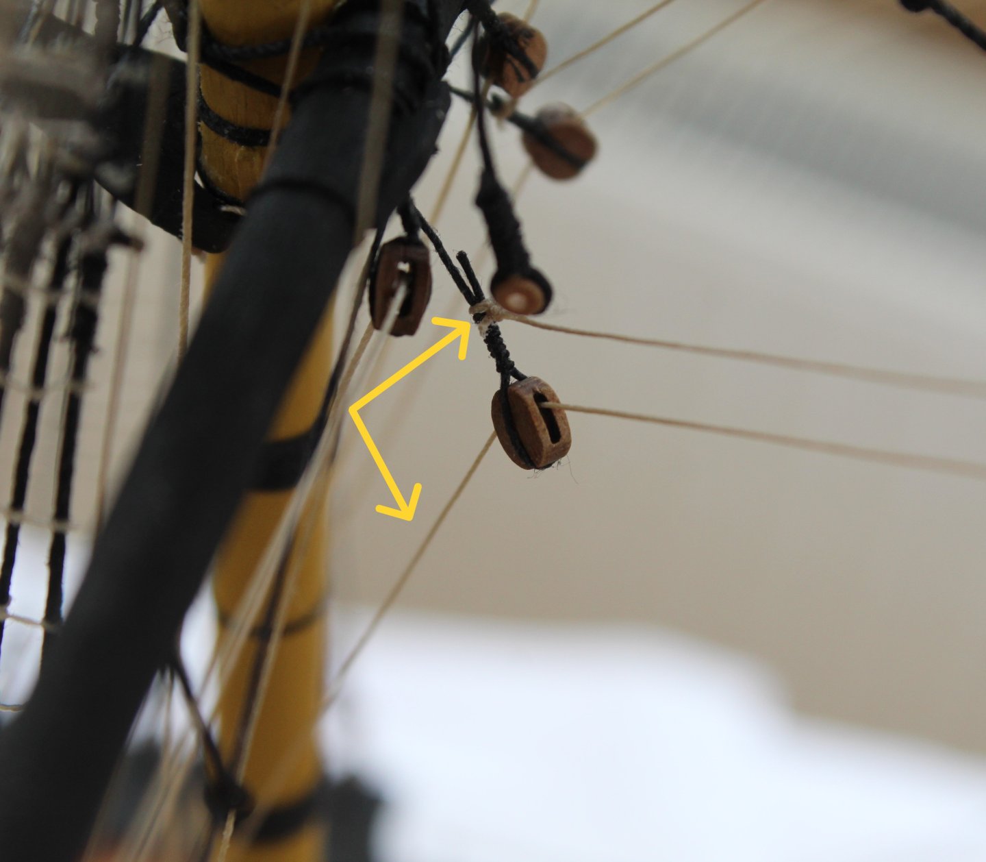
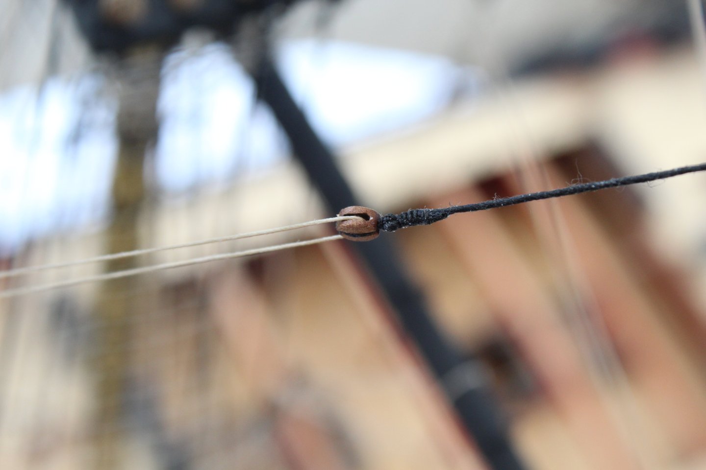
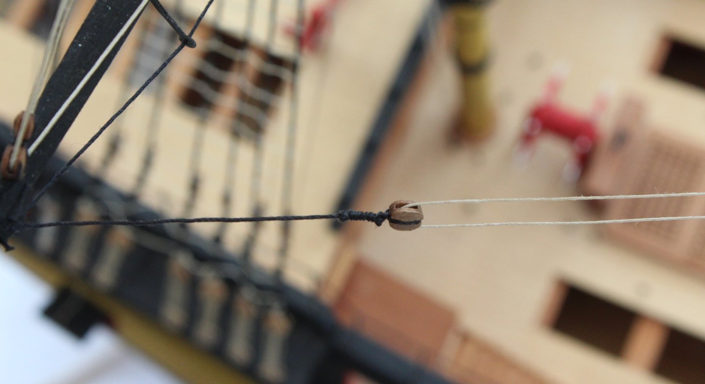
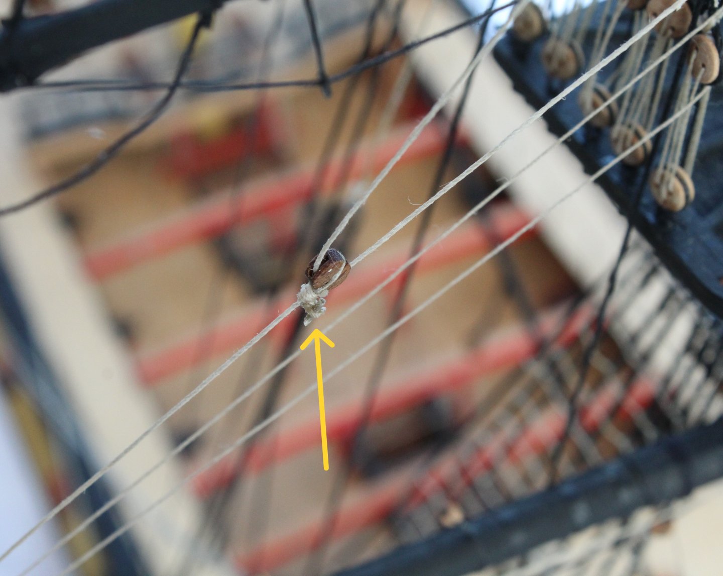
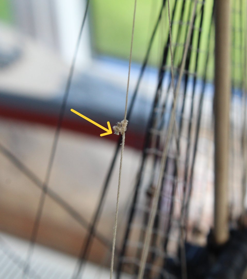
Current Progress I am making good progress at the moment. I now believe I have now completed all the rigging required for the mizzen mast and yards and I am now working on the main mast yard rigging. I have attached a photo of the current build status. Mizzen Bowlines The mizzen topsail and topgallant bowlines have now been added. I have documented the method I used to complete this task, and the ensuing photos relate to the mizzen topsail bowline rigging. I started by taking a length of thread and ran it through a beeswax block a couple of times Next I used a hair dryer to melt the wax which stiffened the thread a little bit. I have found rigging much easy with this process. Next the thread was wrapped around the topsail yard and the seizing was added as can be seen in the photo (out of focus) below. The position of the seizing was then adjusted so the loop, that had been formed, was tight around the topsail yard. The excess thread material was trimmed and a drop super glue applied to the cut ends. The free end of the thread was then fed through a block located on the main mast shroud line and was then taken down to the deck level, as shown in the next photo. The bowline was then belayed as shown in the next photo. A touch of ca glue will be applied before the excess material is trimmed. Main Yard Braces The next task was to add the main yard braces. This was a relatively simple task to complete. A hook was seized to one end of the brace rigging. Once that was done the rigging was fed through the block (flying lead) on the end of the main mast. This is shown on the next photo The hook was the placed in the eyebolt and the other end of the thread was belayed. Main Topsail Yard Braces Next I added the rigging for the main topsail yard braces. This was slightly more complicated due to access. The braces were secured to a block located on the mizzen mast below the crossyard jack. This is shown in the next photo. The return path is also shown where the brace is taken down to the deck level. The next photo shows the belaying. The excess material will be removed.


- 587 replies
-
- 12
-
-
- Indefatigable
- Vanguard Models
- (and 1 more)
-
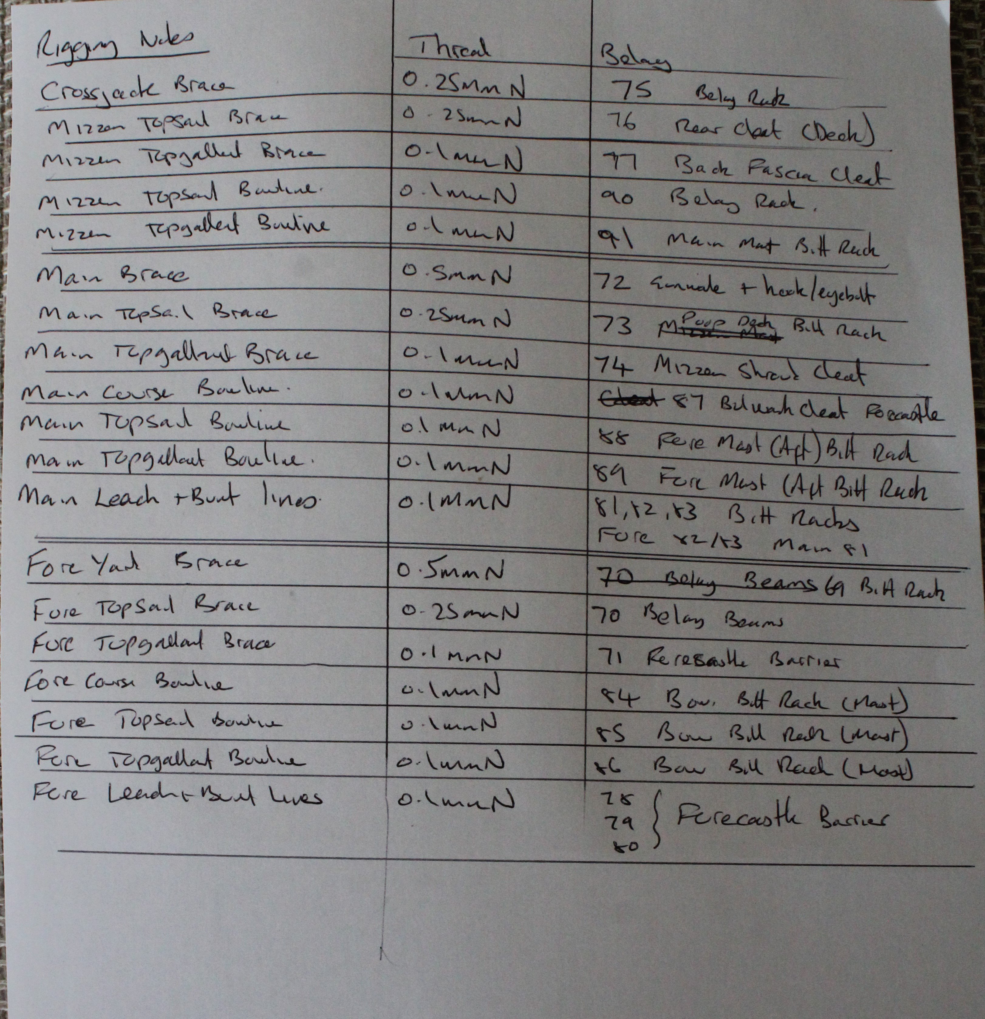
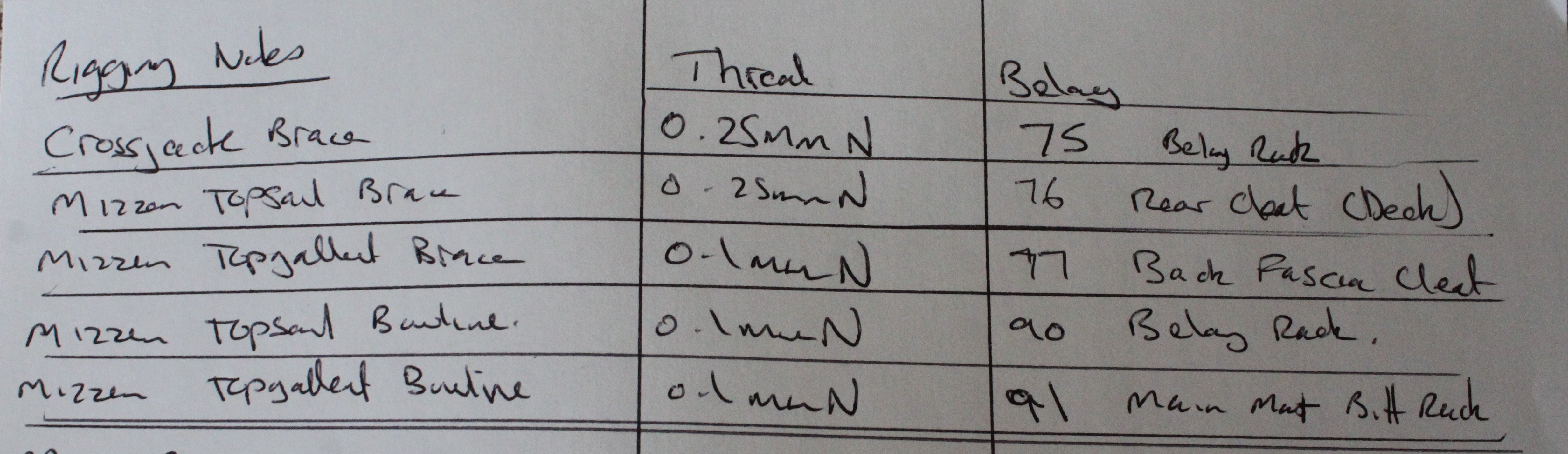
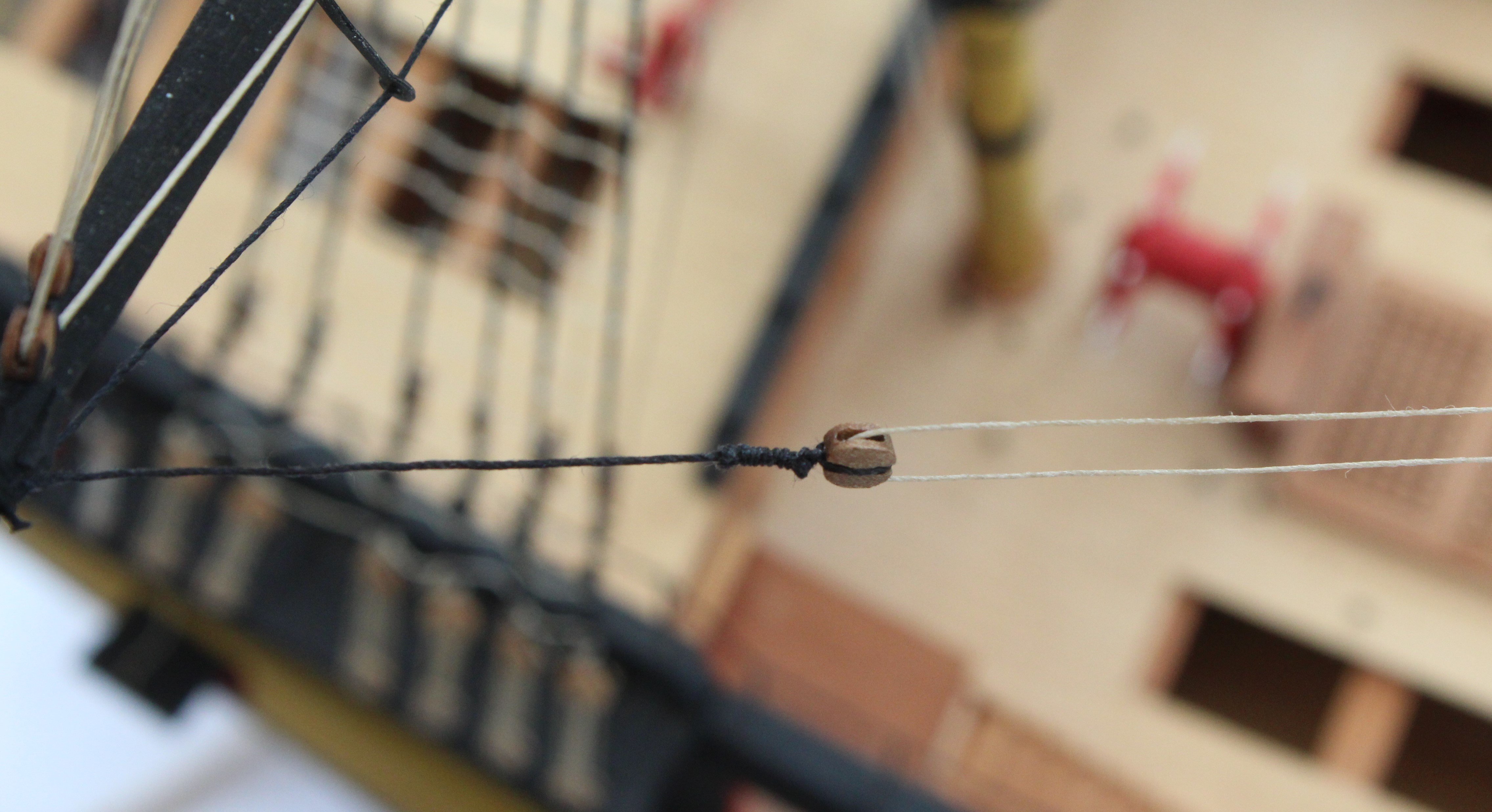
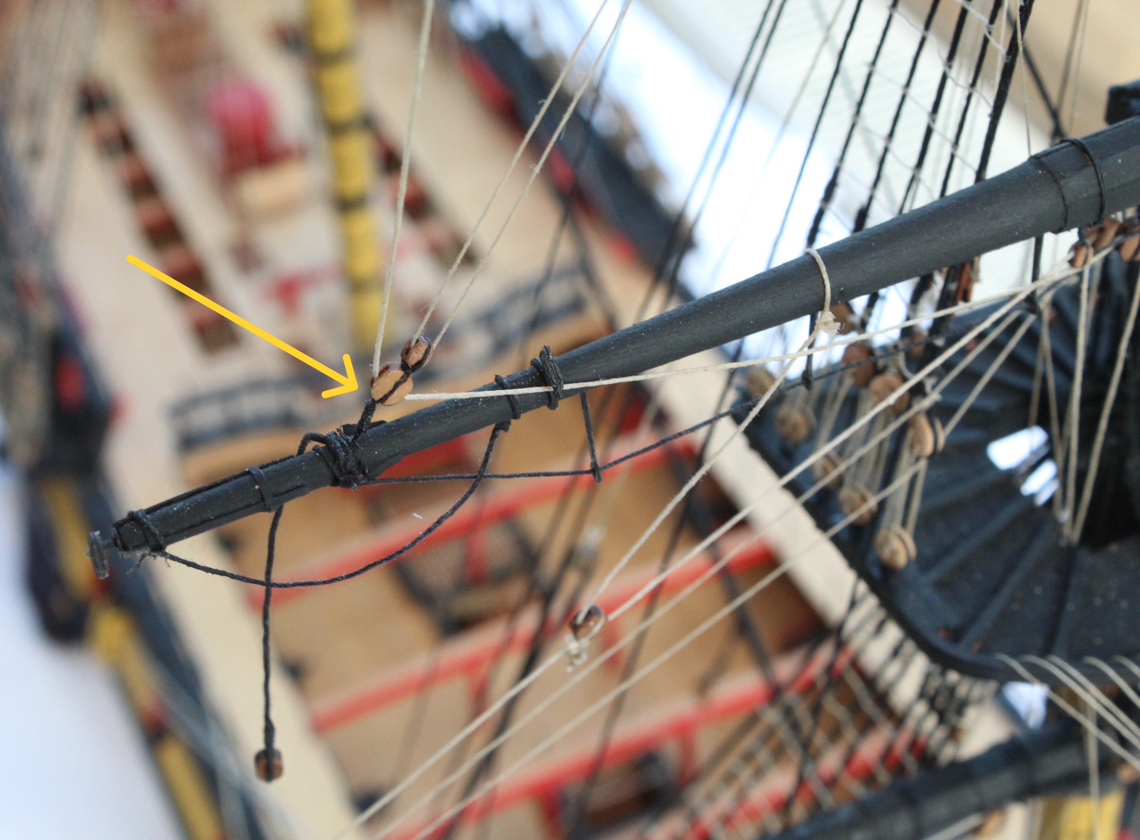
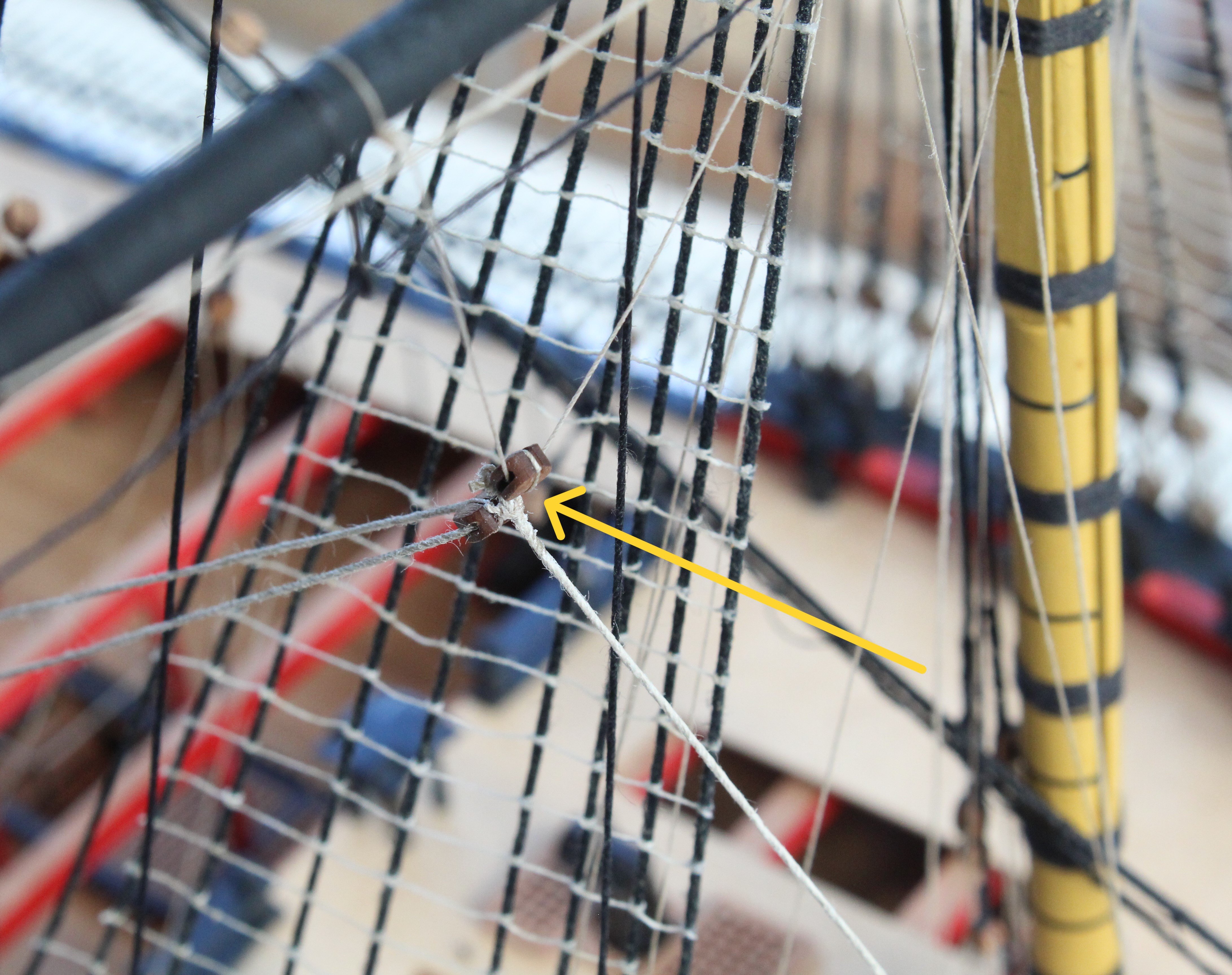
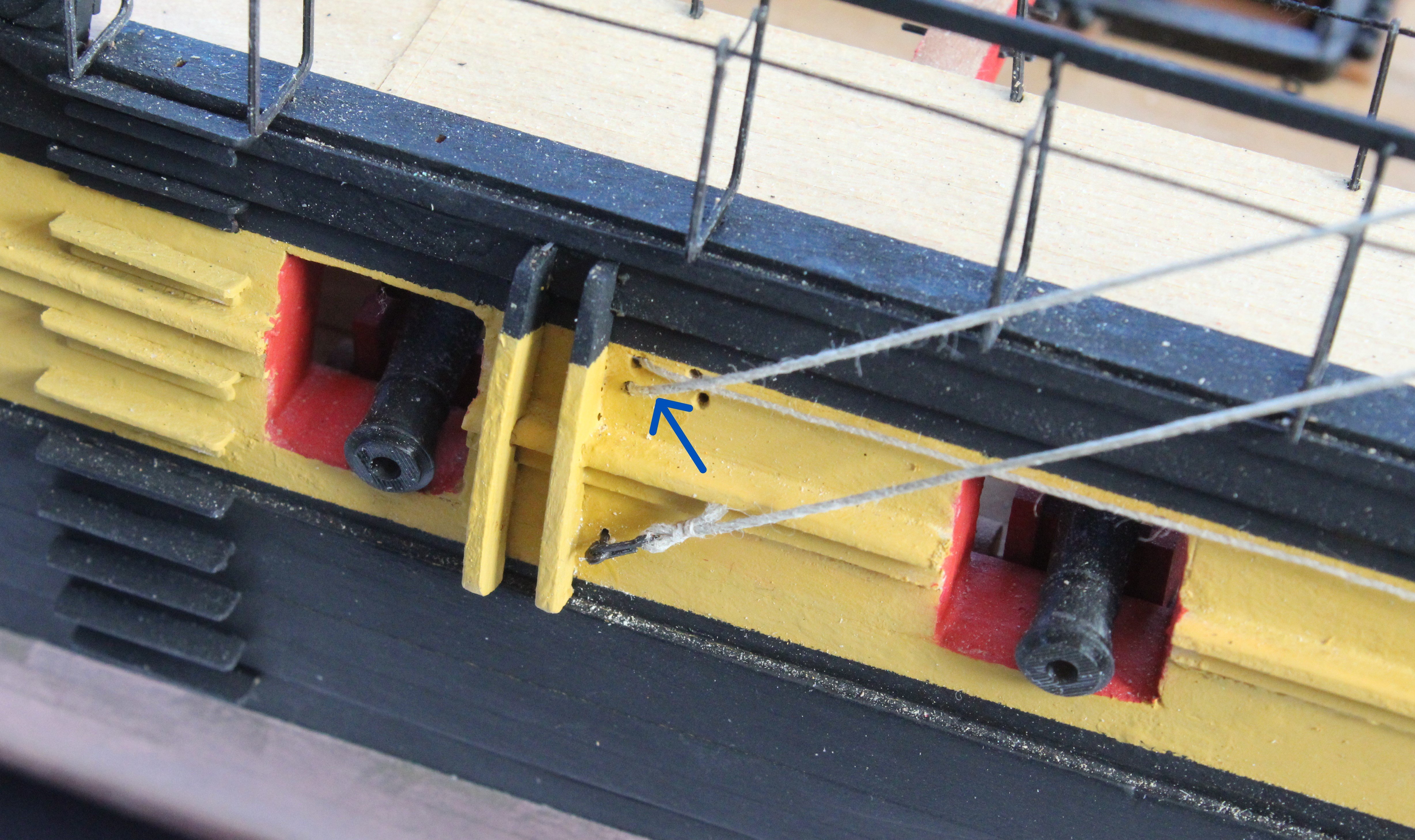
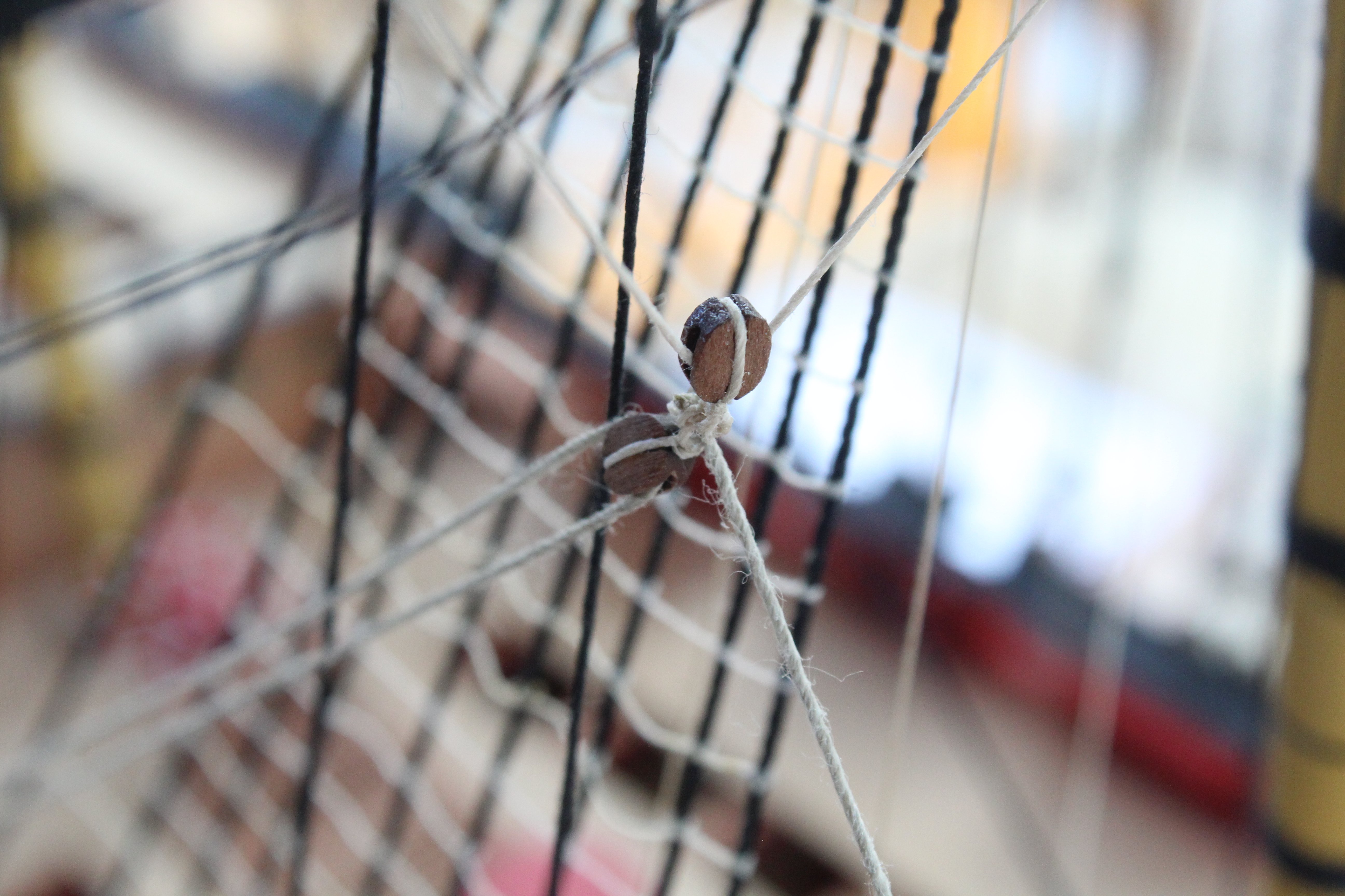
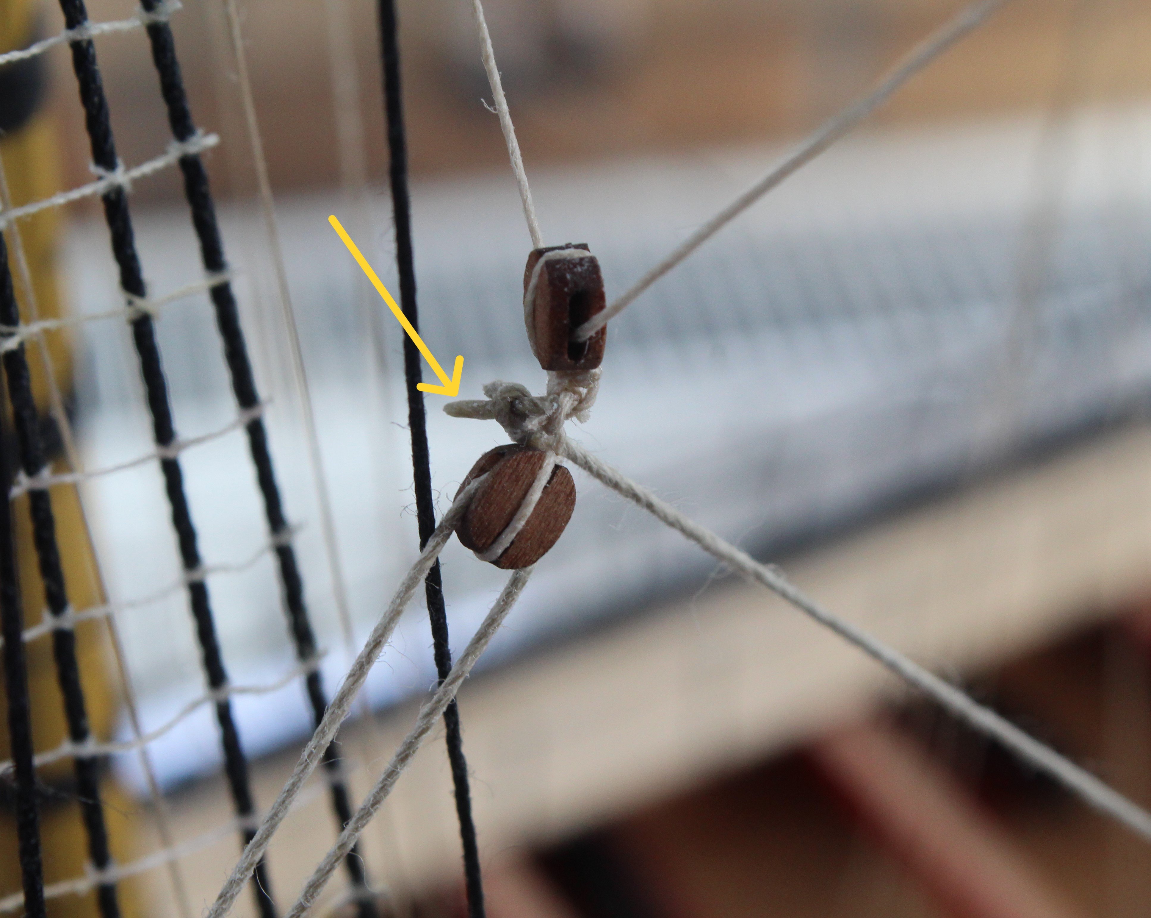
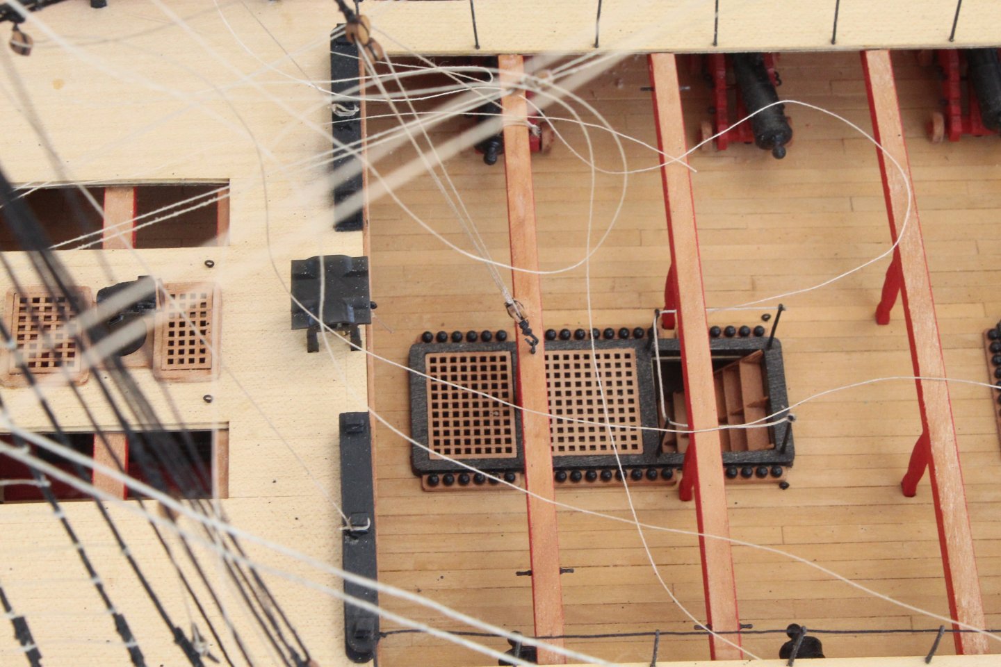
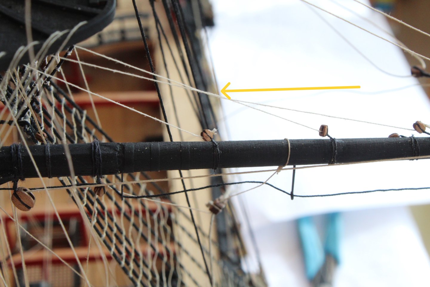
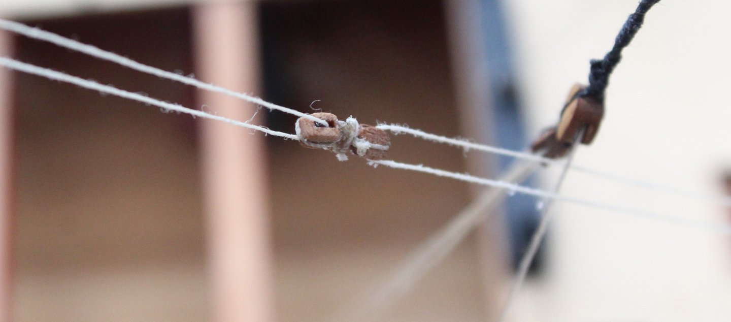
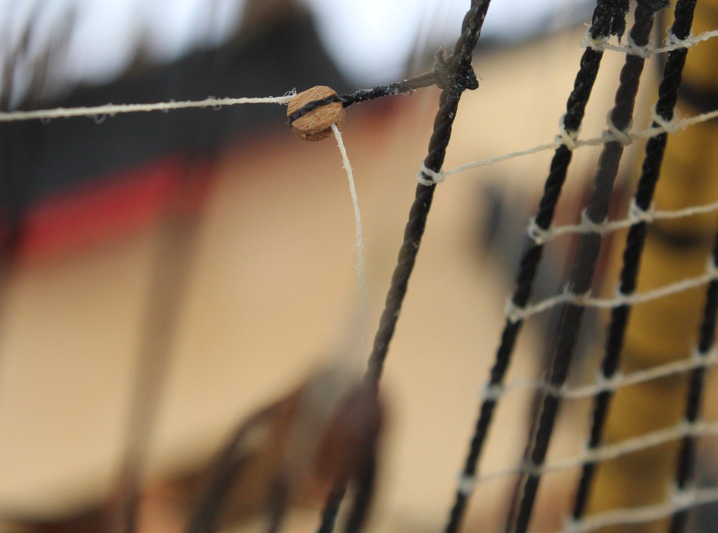
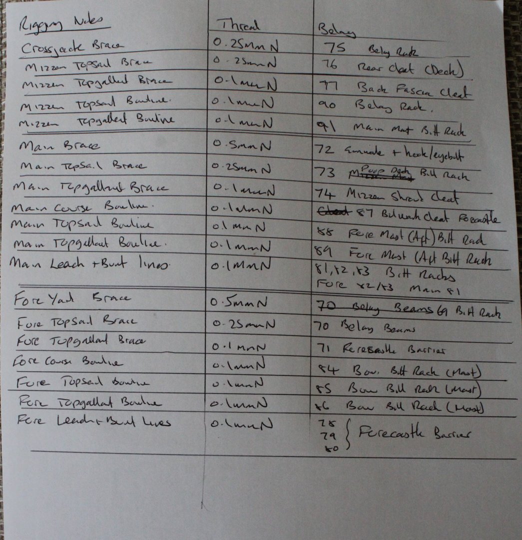
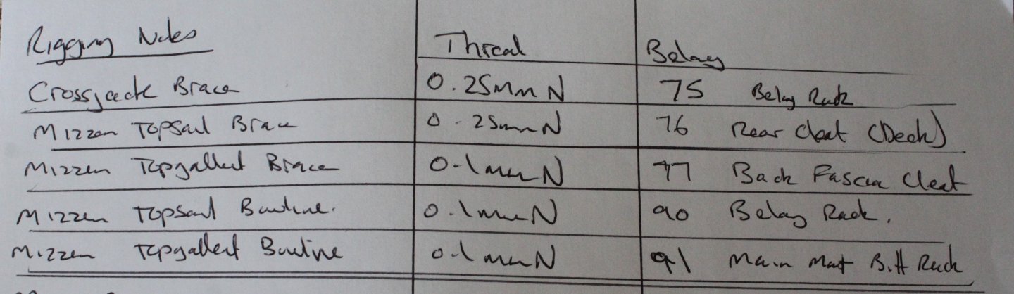
Foremast Yard Sail Sheets and Clew Line Following on from my last post I have now taken a few photos of the completed fore mast / yard sail sheets and clew lines The next photo shows one of the clew line blocks, where the sheet line is attached to it via a toggle, as indicated by the yellow arrow. The next photo shows a sail line that is fed through a block on the end of the fore topsail yard. It is then fed to another block located near the foremast before it is taken down to the deck level for belaying. The next photo shows the double block arrangement for the fore yard clew line and sheets. The next photo shows where the foreyard sheet lines are belayed. It would have looked better if the rigging that is fed through the hull was the other way round (the other line fed through the hull is from the topsail sprit yard sheet rigging) but given the amount of rework that would be required to change this over I am more than happy to live with how it currently looks. The next photo is another example of the toggle joint, this was used for the fore topgallant yard. Mizzen Mast Braces The first task for completing the rigging on the final plan sheet was to make a set of notes detailing the all of the rigging, the thread type and the belaying points. I decided I would start by completing all work related to the mizzen mast / yards as shown below. The next photo shows one of the crossyard jack brace rigging points. The next photo shows where the crossyard jack brace rigging starts (above the block) and then the block where the brace rigging is then fed down to the deck level for belaying. The next photo shows the belaying of one of the crossyard jack brace rigging. The next photo shows one of the topsail yard brace rigging The next photo shows where the topsail yard rigging starts and also shows the block where the rigging is taken down to the deck level for belaying. The next photo show one of the topgallant yard braces. The next photo shows the topgallant yard rigging fed through the blocks before they taken down to deck level for belaying. The next photo shows the belaying of the topsail and topgallant yard braces. The excess thread has not been trimmed. I just have the mizzen bowlines to add and then all work related to the mizzen mast is finished.


- 587 replies
-
- 10
-
-
- Indefatigable
- Vanguard Models
- (and 1 more)
-
Alan I will keep posting, many thanks for your kind comments.
- 587 replies
-
- 2
-
-
-
- Indefatigable
- Vanguard Models
- (and 1 more)
-
Progress Update I have completed adding the various sheets and clew line the fore, main and mizzen yards (lower, topsail and topgallant). This means that I have now completed all the rigging shown on plan sheets 16, 17 and 18. I just have to add the rigging shown on plan sheet 19 which deals with the yard braces, bunts, leach and bowlines. The end is in sight and hopefully I can complete this before we depart for a trip down the Blue Danube at the end of July. Sorry no photo's with this post but I will try to take some in the next day or two.
- 587 replies
-
- 5
-
-
- Indefatigable
- Vanguard Models
- (and 1 more)
-
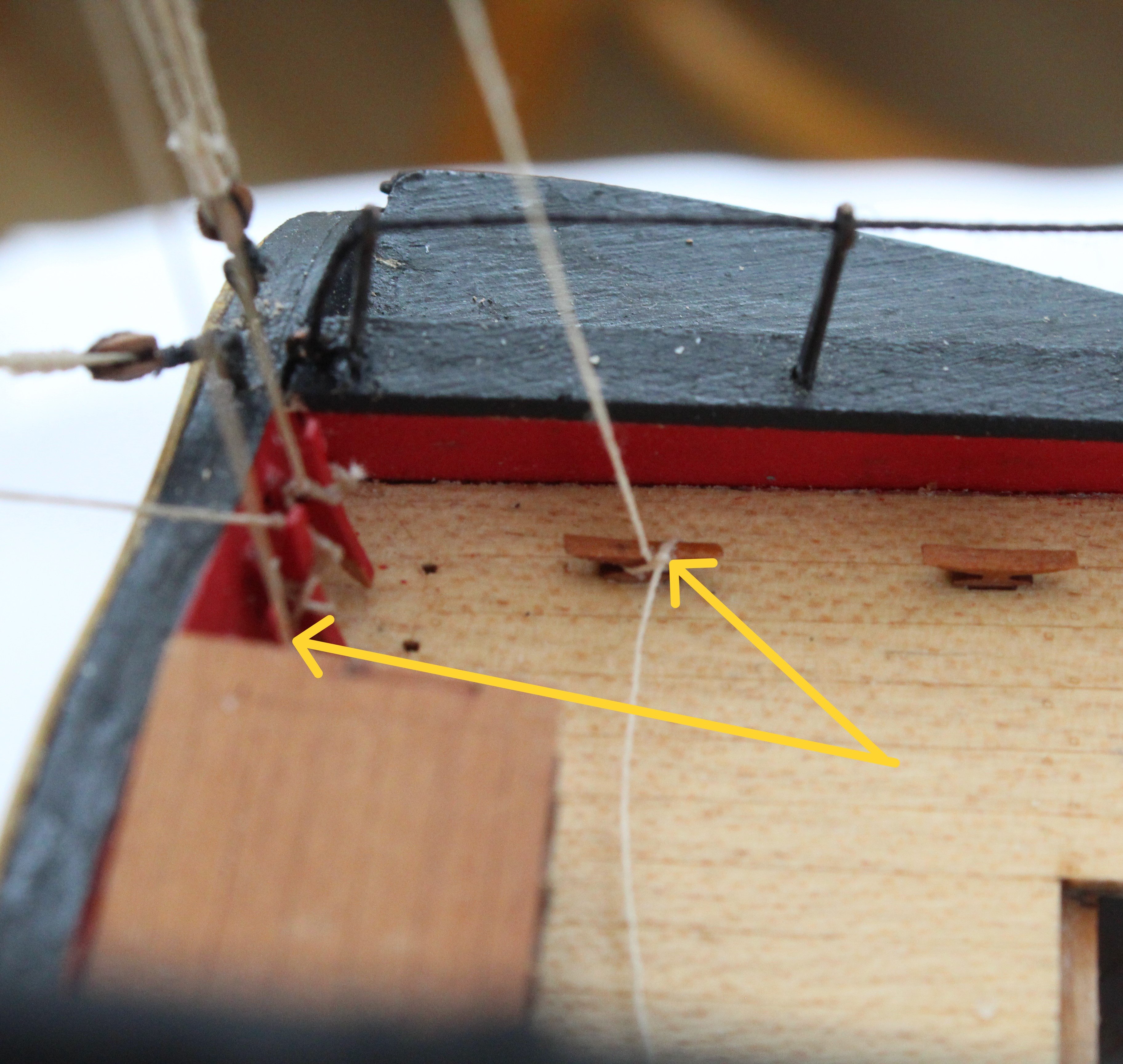
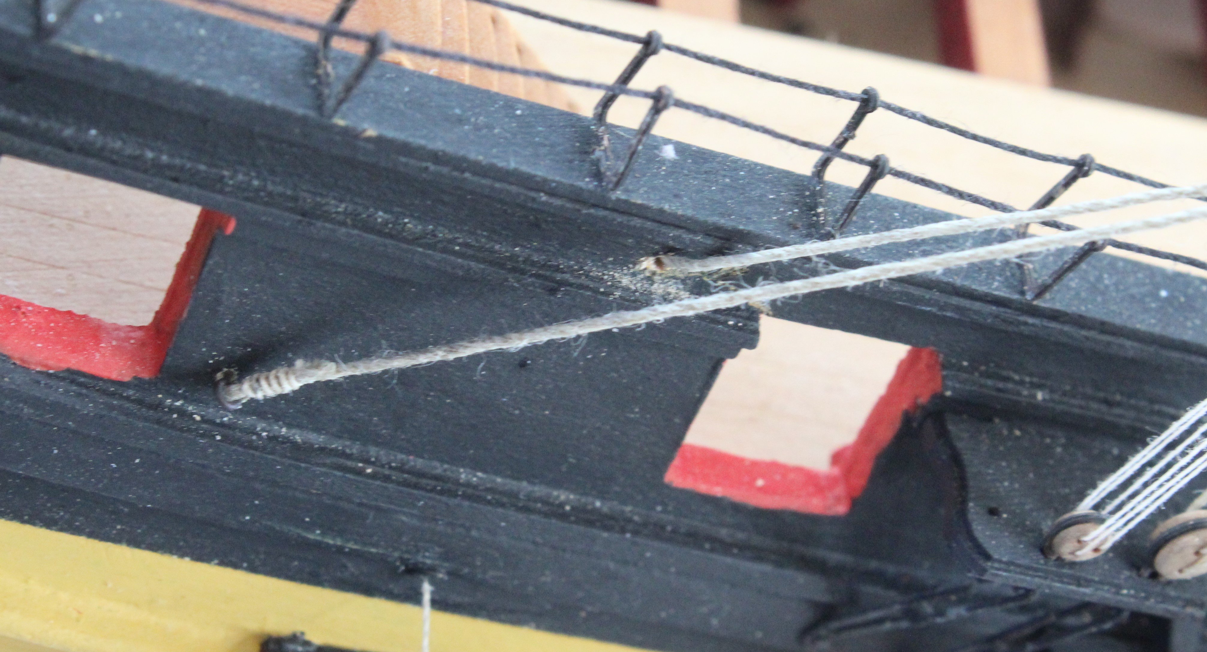
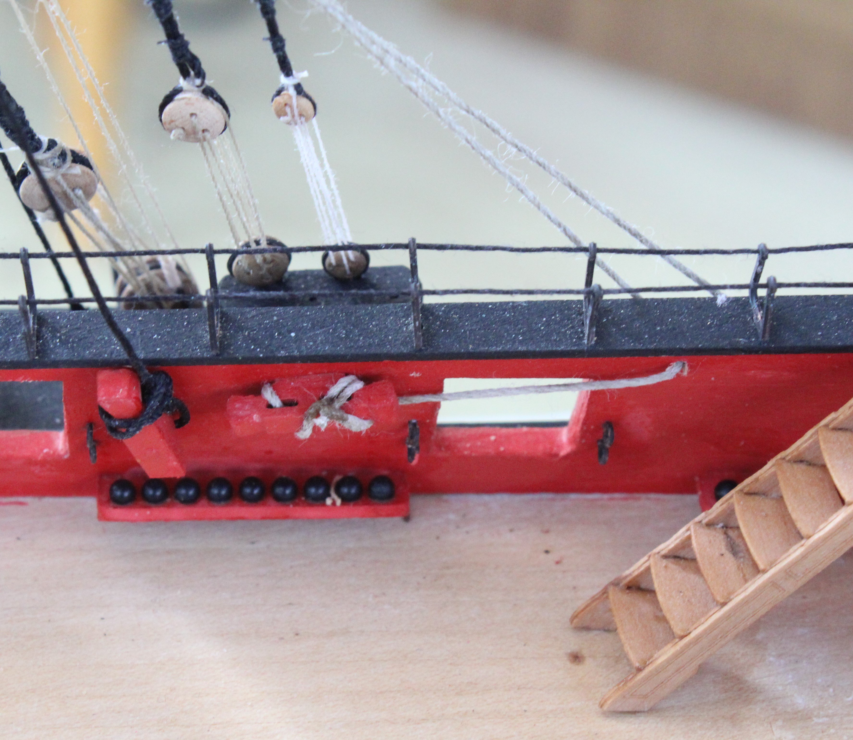
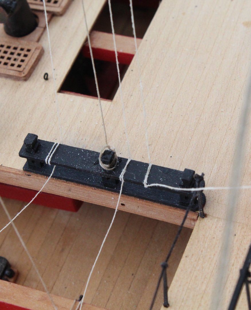
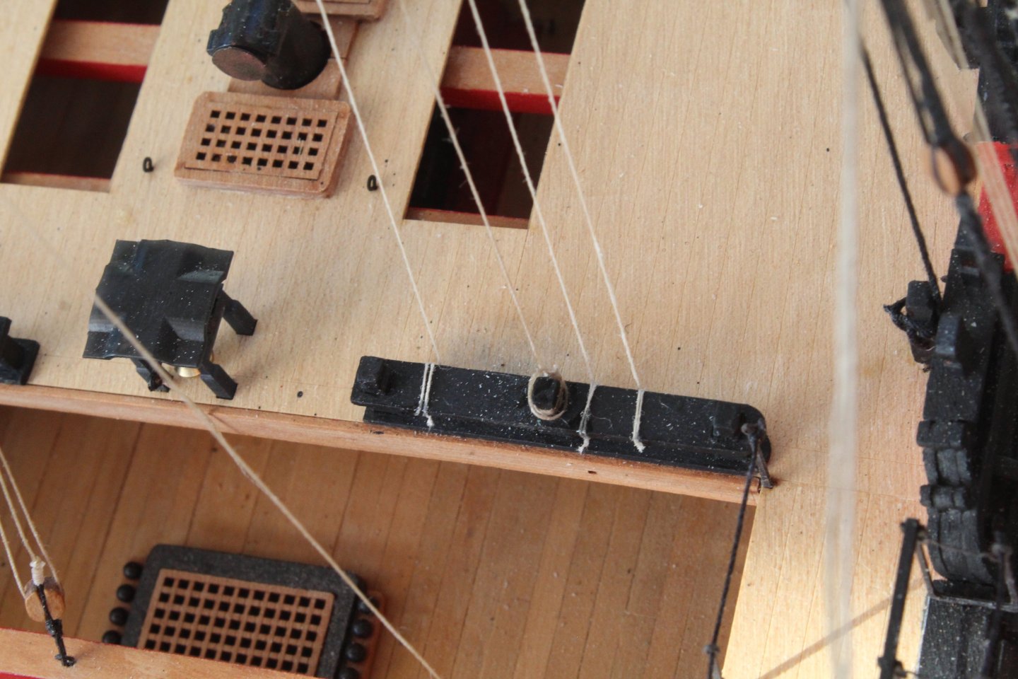
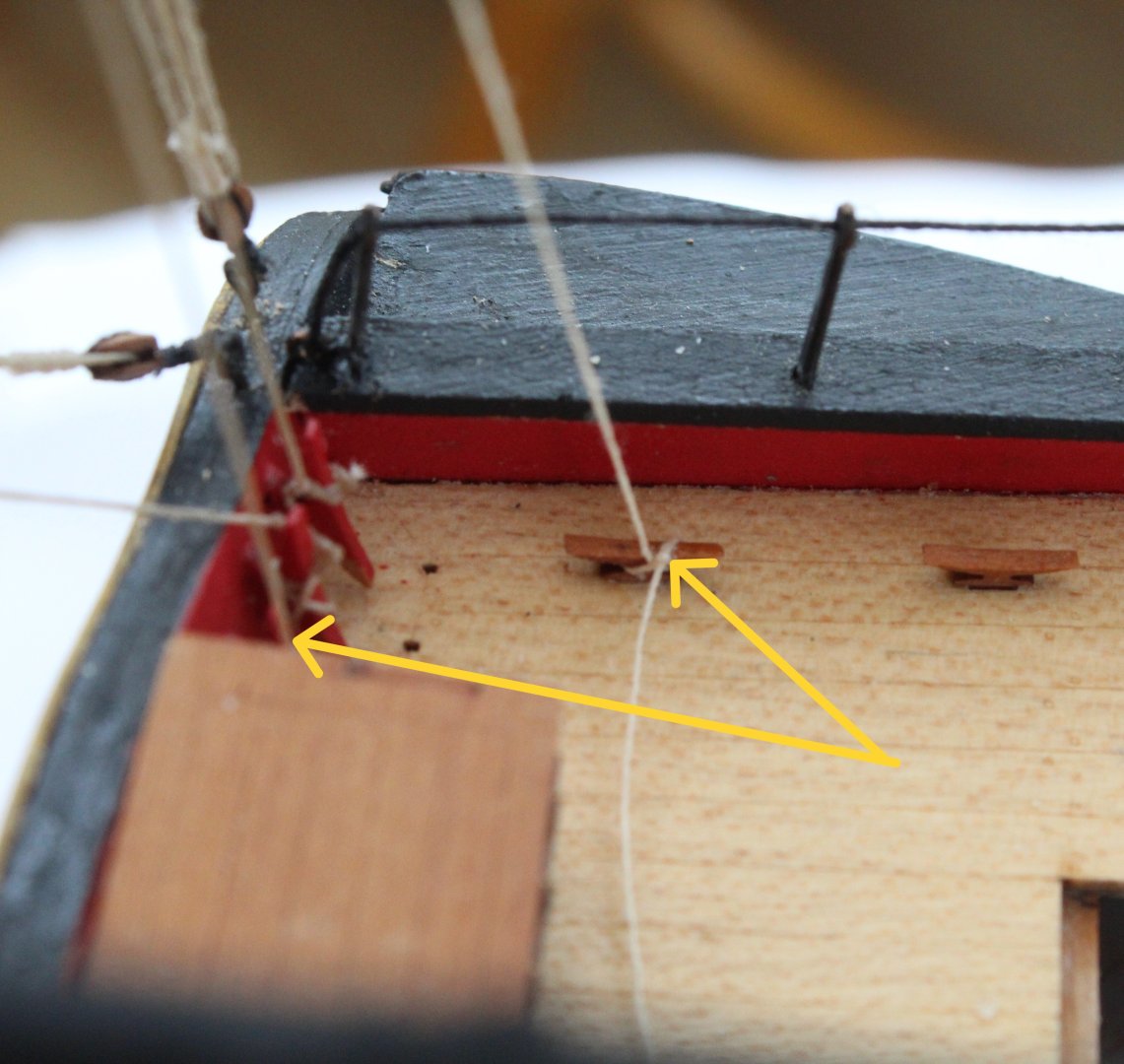
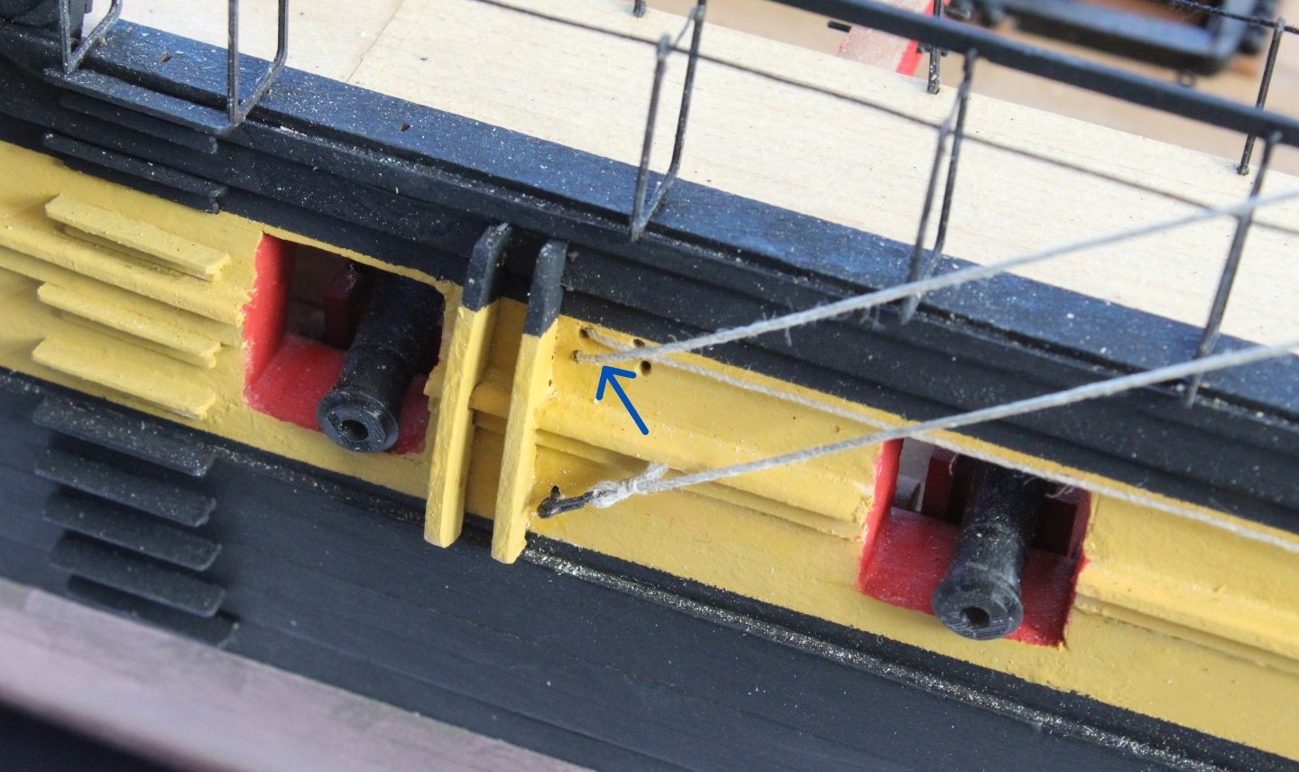
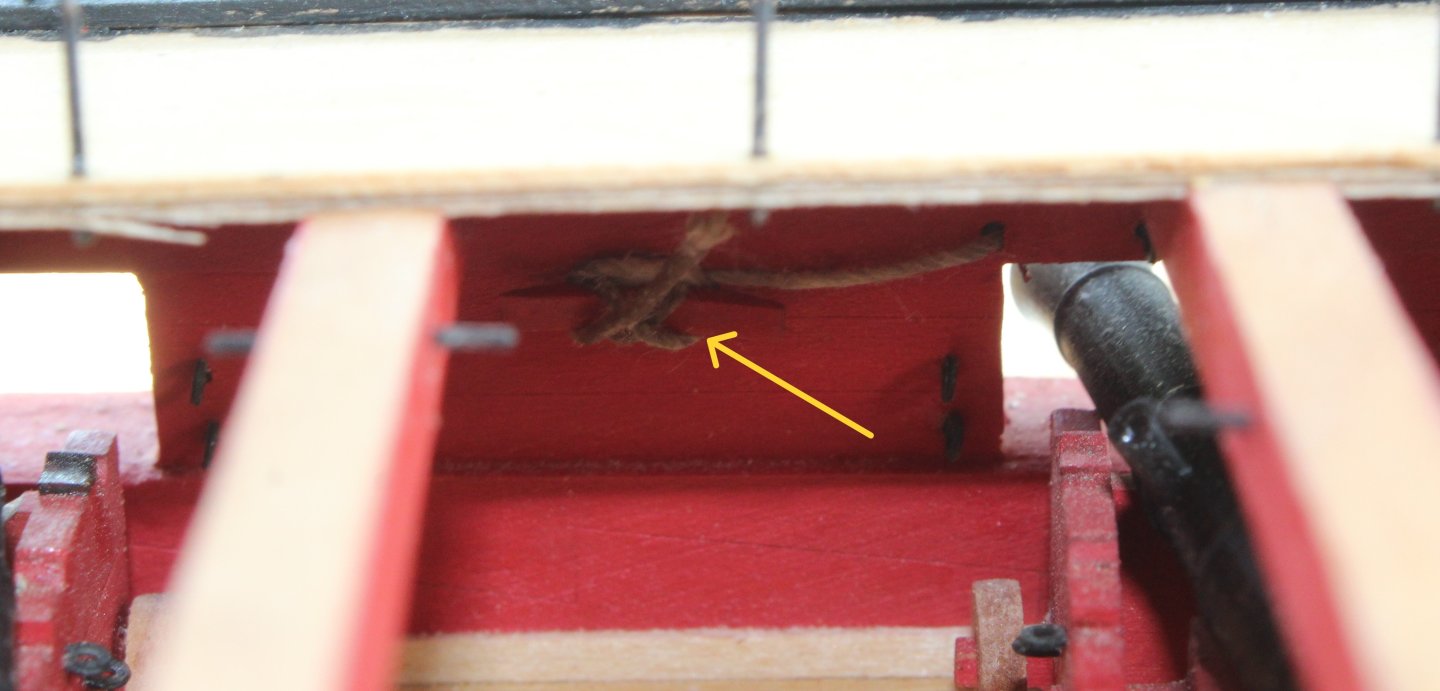
Main Yard Sheet and Clew Line This was an interesting and time consuming task to complete. I started the process by making the double block arrangement which are joined together and a separate line with a toggle is passed through one of thimbles on these blocks. These blocks were then secured to the main yard and the free end was then passed through one of the yard blocks before it was taken down to the deck level. The free end was belayed to the bitt rack located on the gun deck. The line with the toggle was fed though a hole on the hull and then belayed to an internal cleat located under the gangway. This was very tricky to complete due to the access. The final task was to run the rigging from the other block. One end was secured outside the hull using an eyebolt. The other end was fed through the hull and then belayed to an internal cleat.


- 587 replies
-
- 14
-
-
- Indefatigable
- Vanguard Models
- (and 1 more)