HOLIDAY DONATION DRIVE - SUPPORT MSW - DO YOUR PART TO KEEP THIS GREAT FORUM GOING! (89 donations so far out of 49,000 members - C'mon guys!)
×


Glenn-UK
-
Posts
3,162 -
Joined
-
Last visited
Content Type
Profiles
Forums
Gallery
Events
Everything posted by Glenn-UK
-
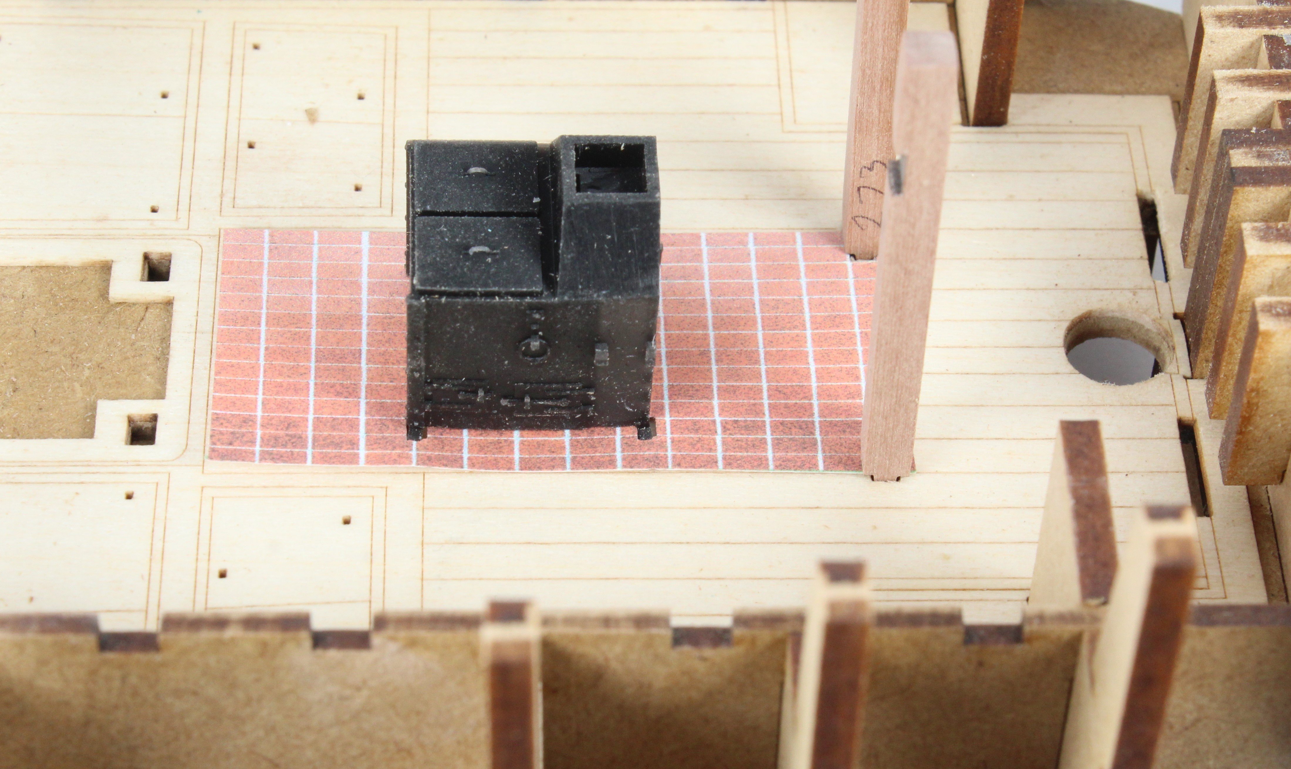
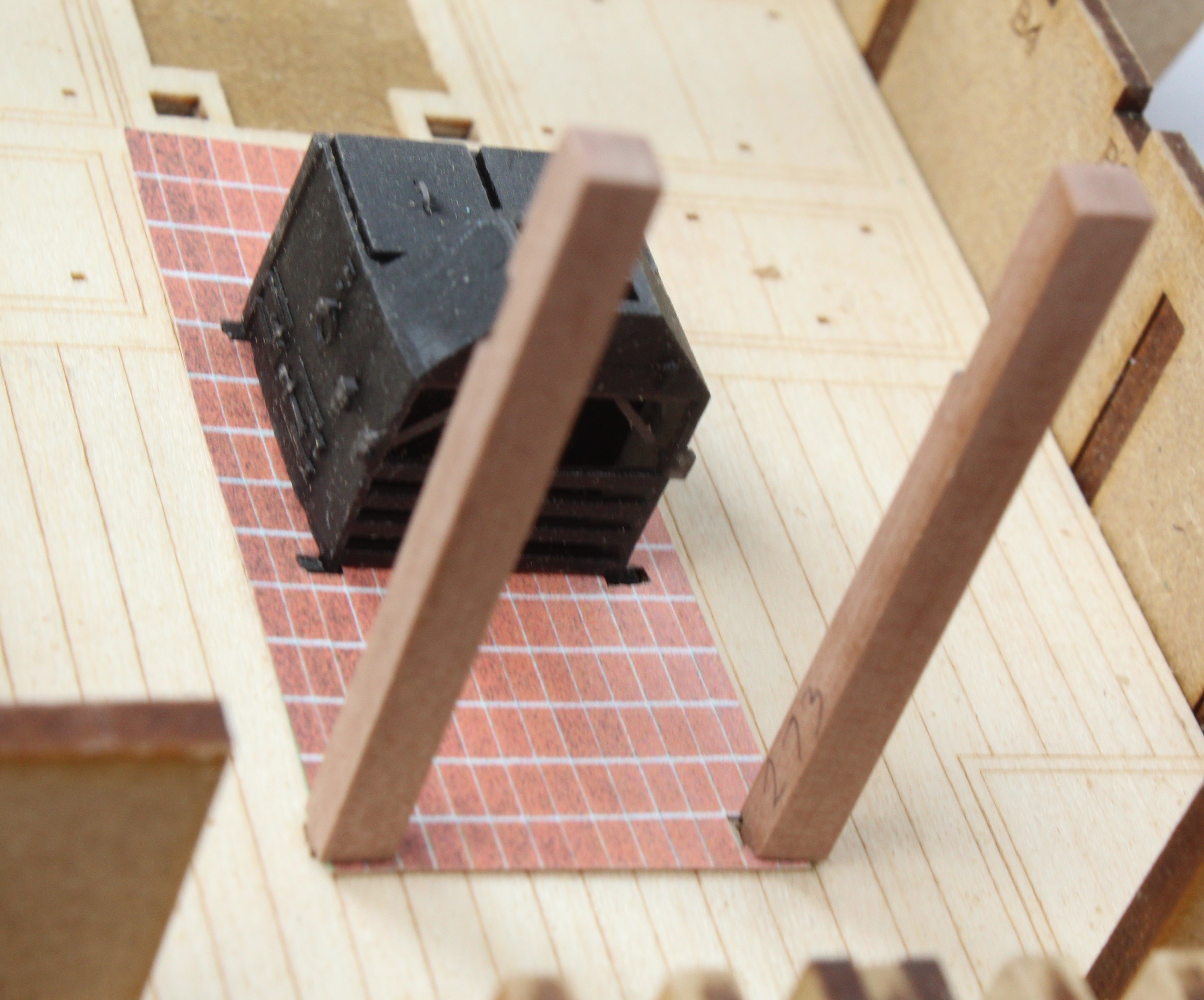
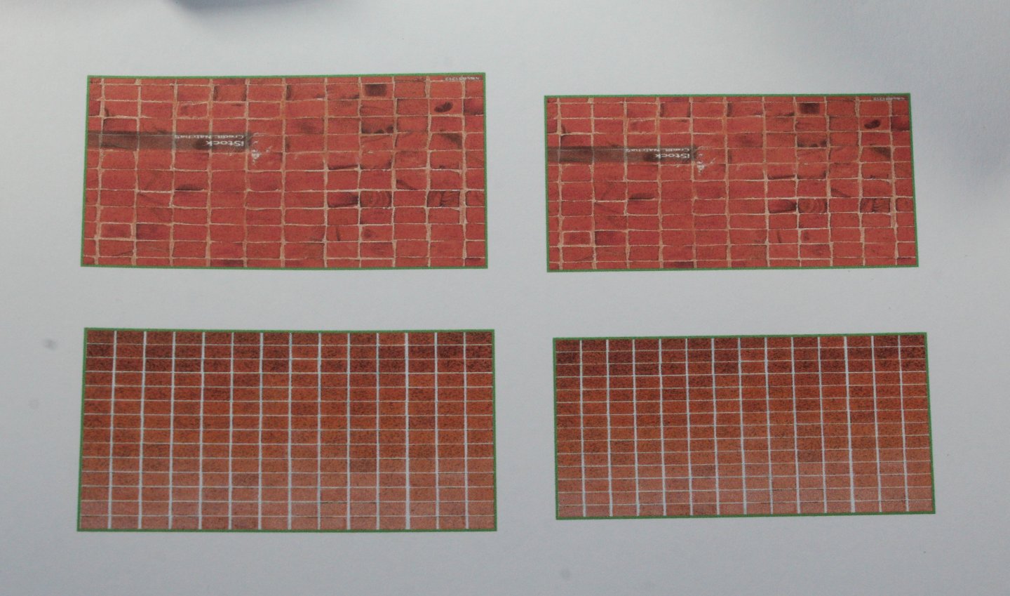
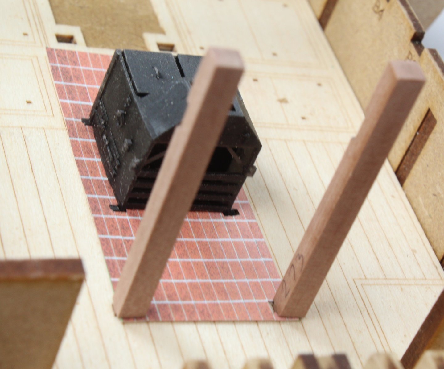
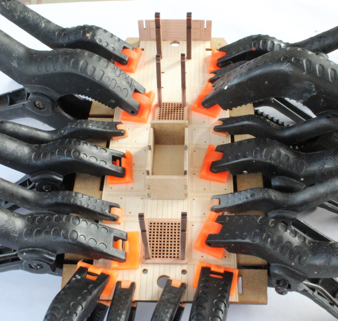
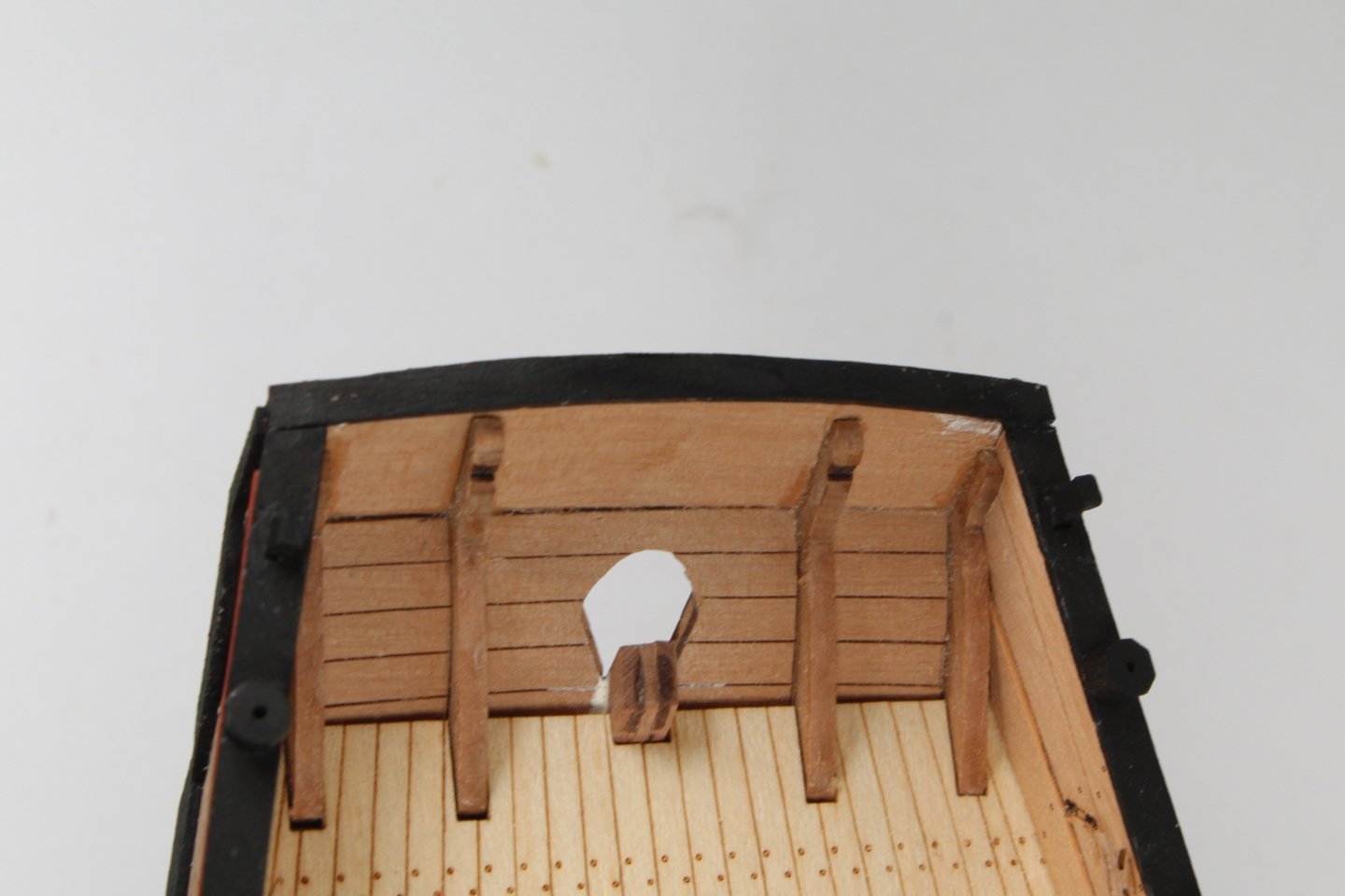
 Following on my last post I have now removed the laser char from the all the deck beams and additional filler pieces. With another dry fit all the parts are a perfect fit. At this stage it is always a good idea to check the various dowels will locate through the various access holes. As can be seen in the following photo there are no issues. I really liked @Blue Ensign idea of adding a stone floor effect to the stove area. After looking for some suitable image files I downloaded a couple of different patterns. Once I had resized the images they were printed out. Although I prefer the top pattern, as shown in the photo below, there is an embedded watermark which means I am unable to use that image. After carefully cutting the holes for the bitts and stove I did a trial fit of the pattern. Overall it does not look too bad. I will need make another floor tile pattern as the one shown below is a tad too small. I am also deciding weather to glue the floor tile pattern to a 0.8mm wooden base before adding it to the deck. I will also compare the floor tile pattern with a version printed on photographic paper. This will probably be a bit bright and shiny.

- 241 replies
-
- 14
-

-
- Vanguarrd Models
- Harpy
- (and 1 more)
-
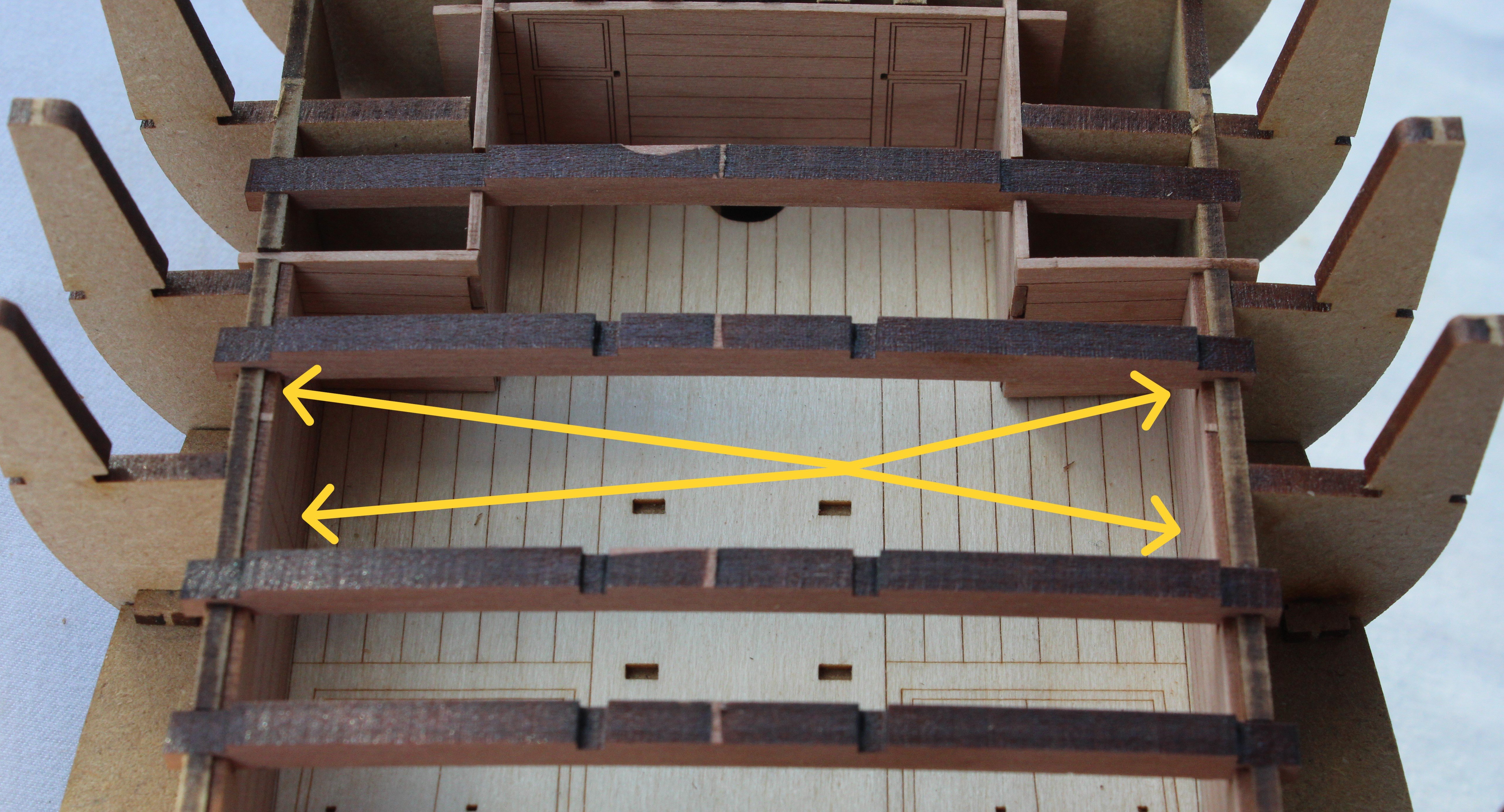
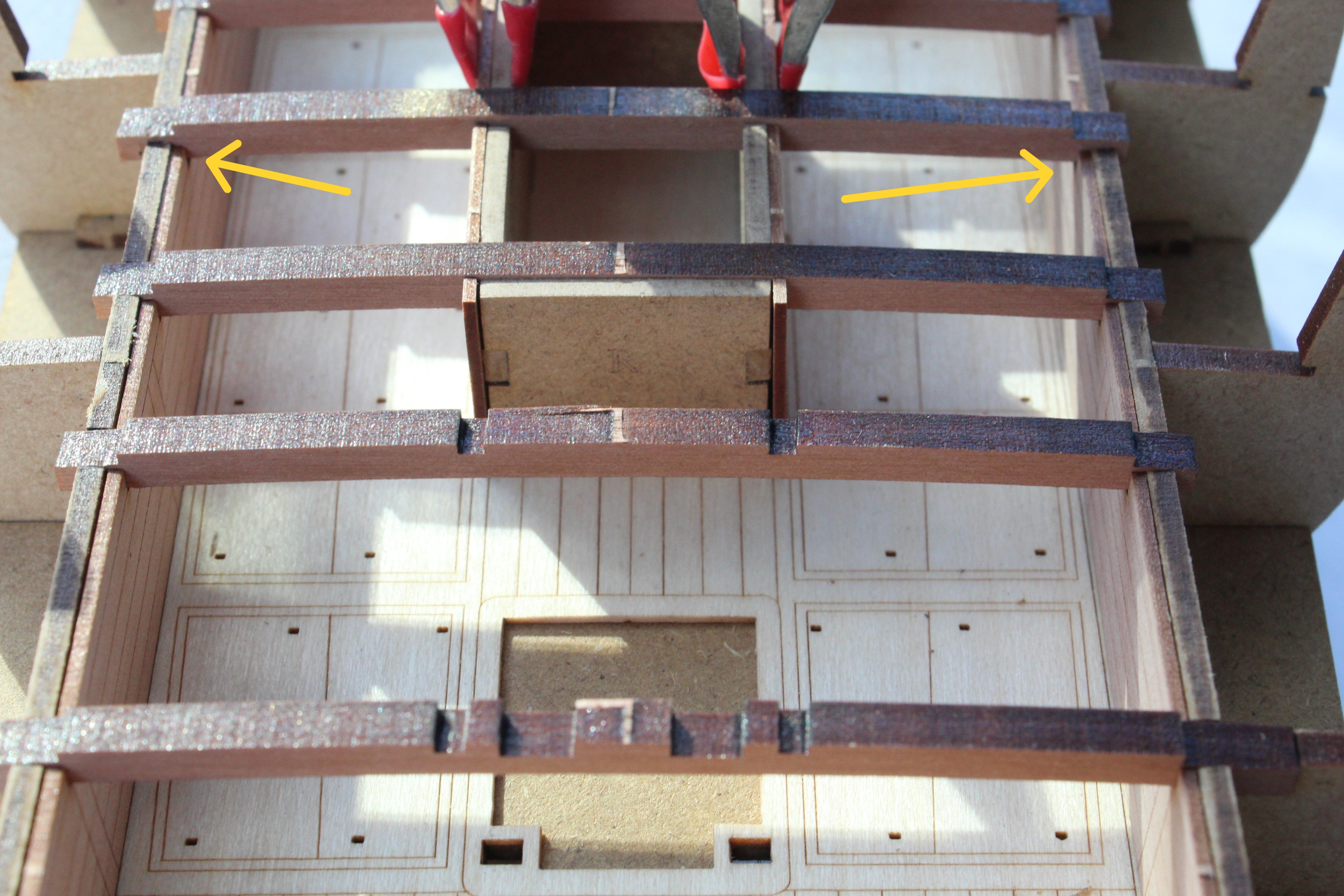
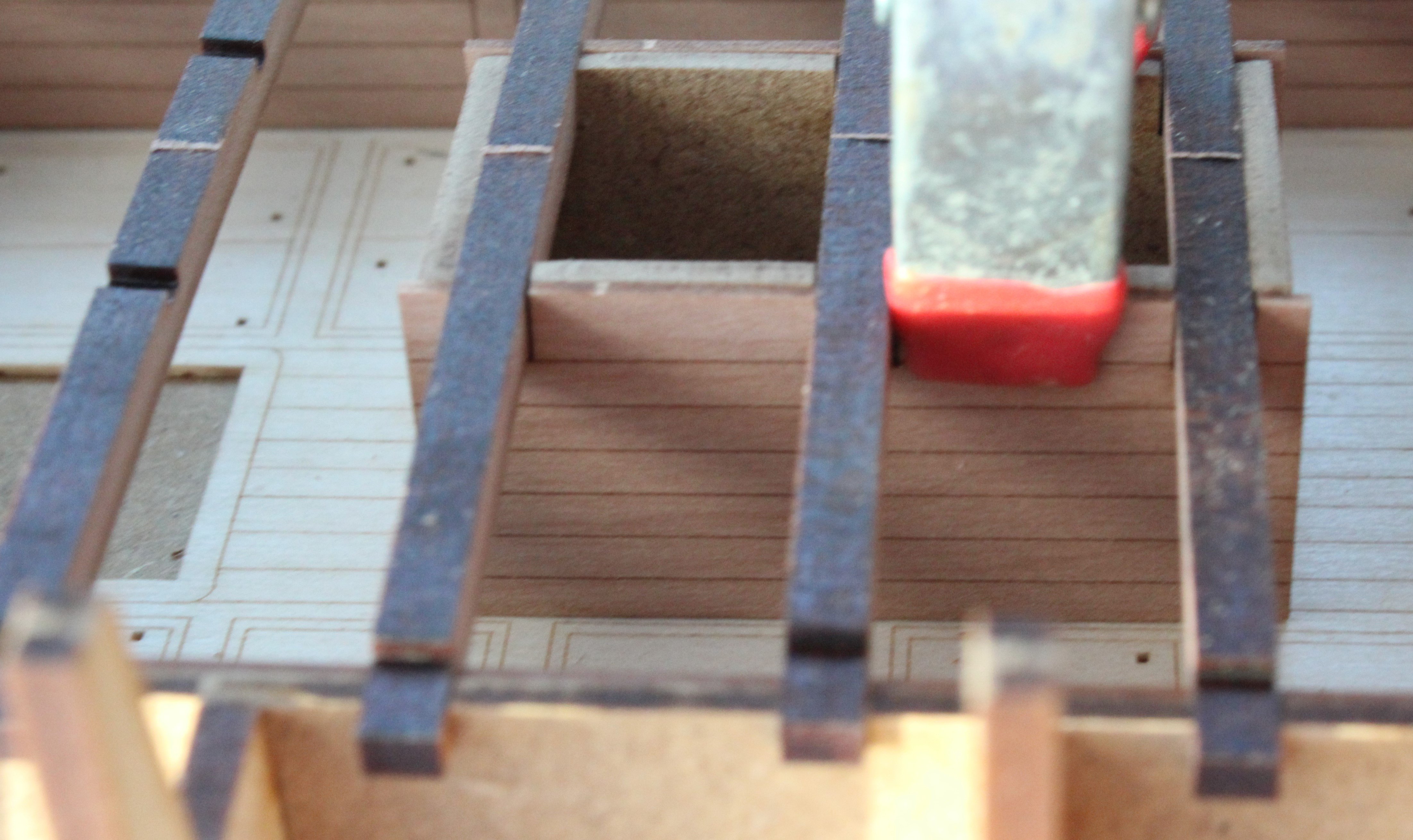
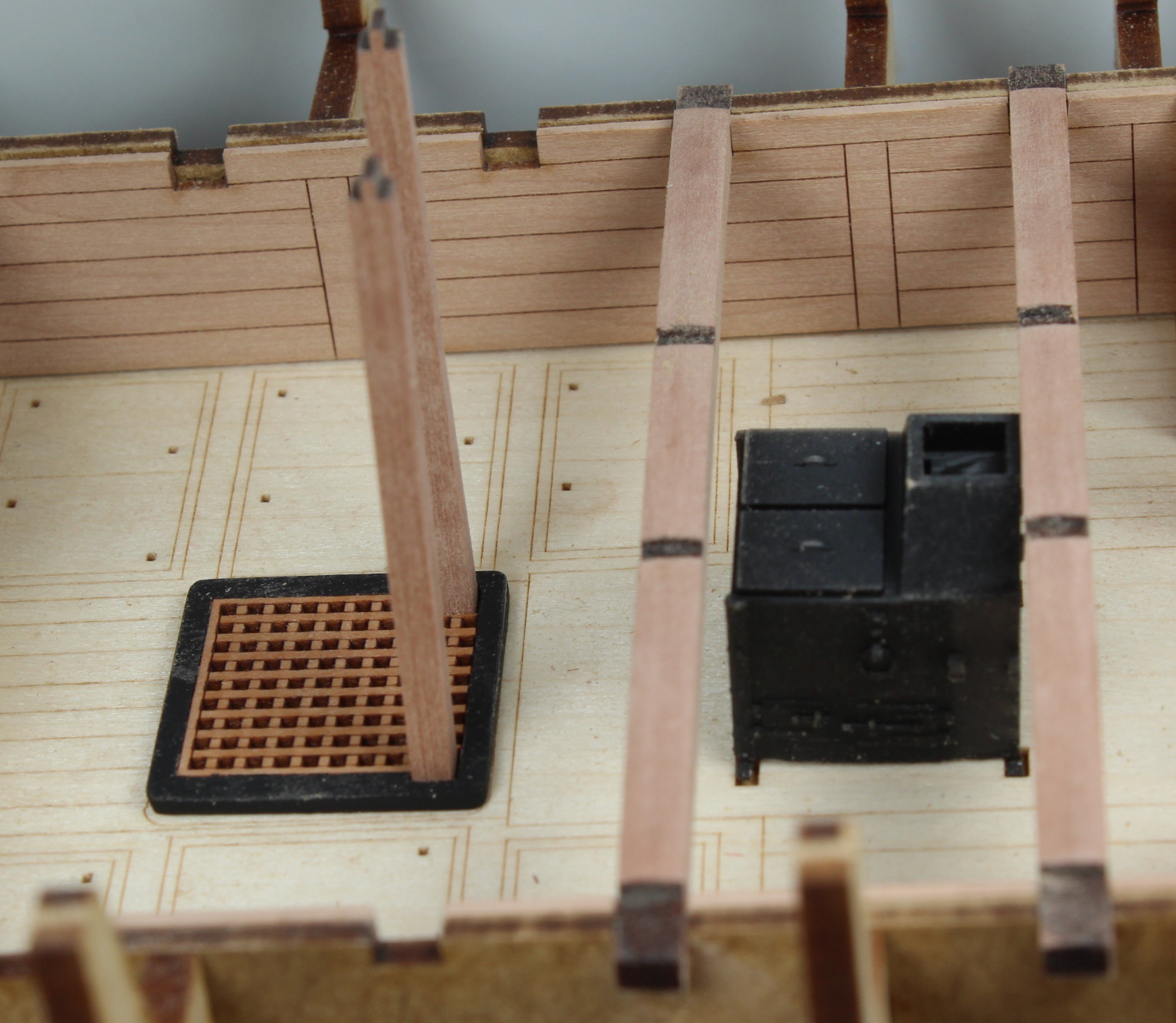
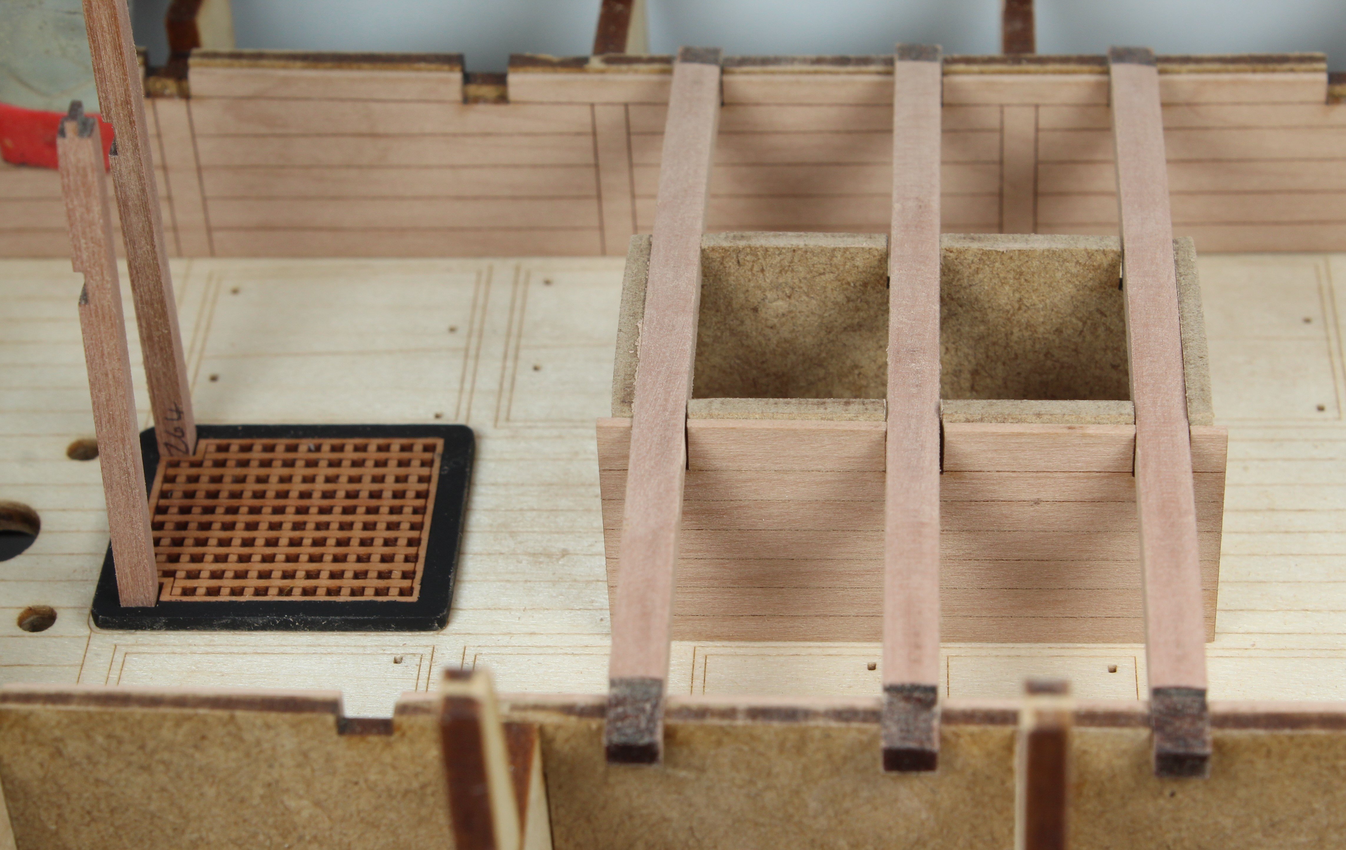
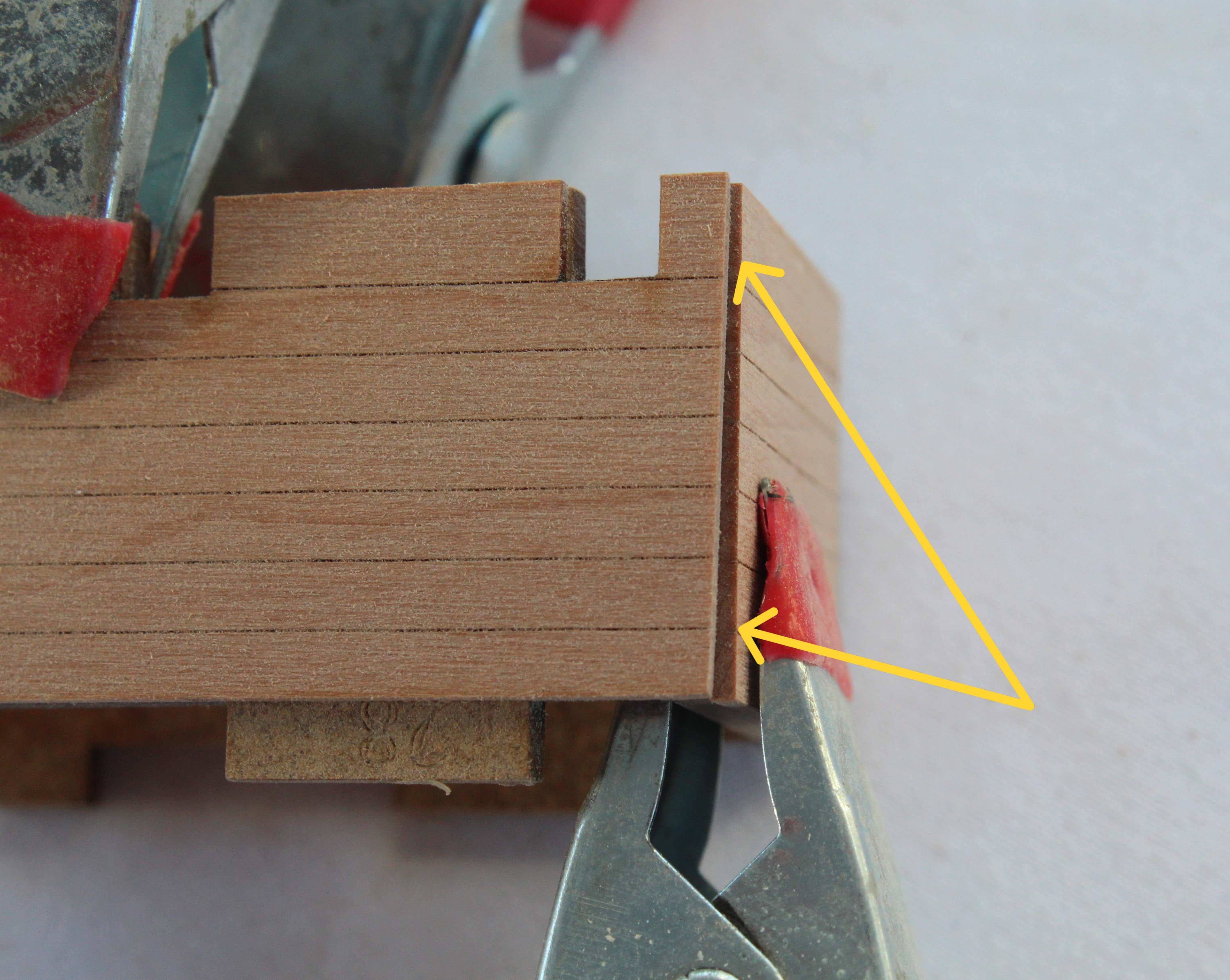
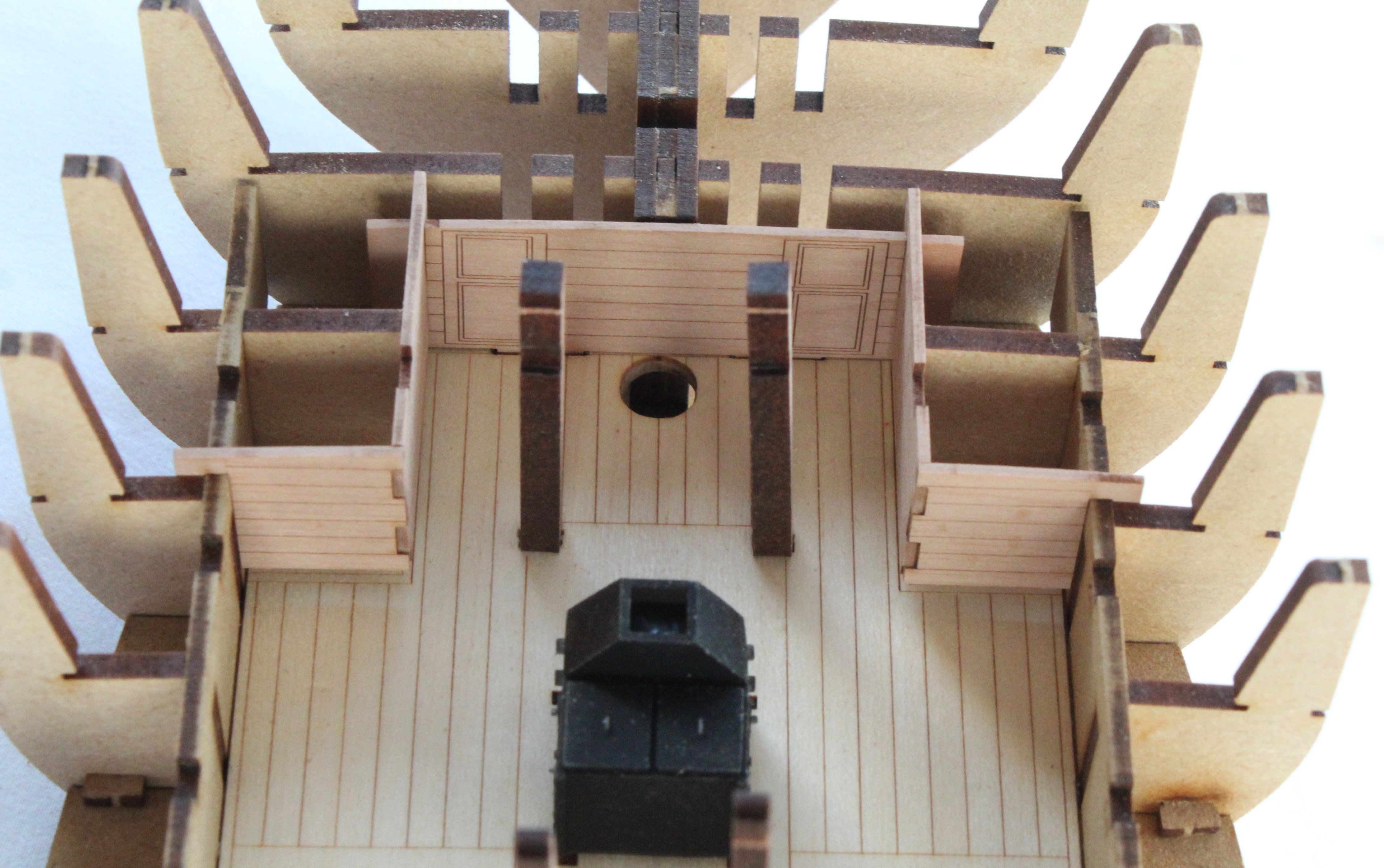
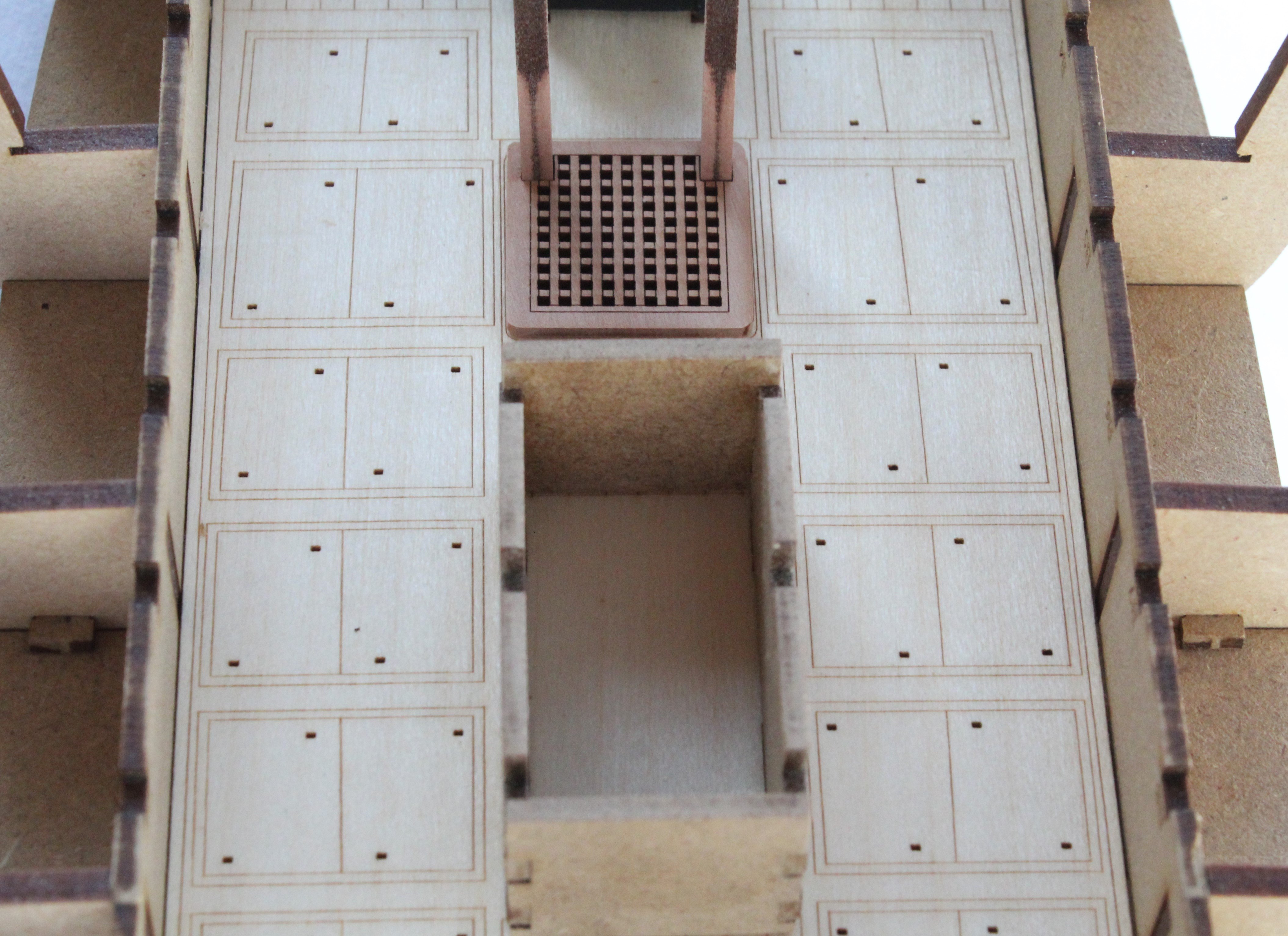
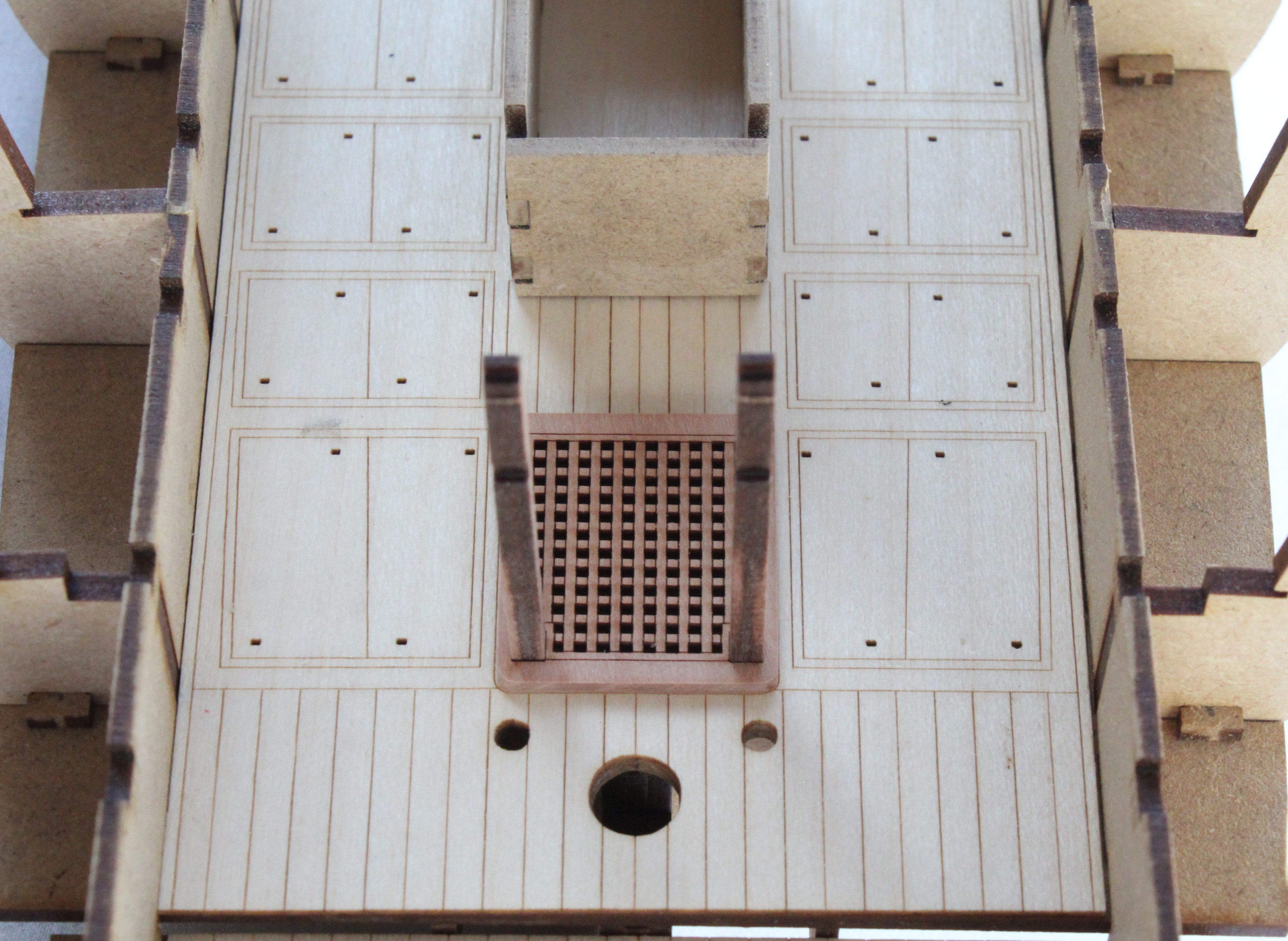
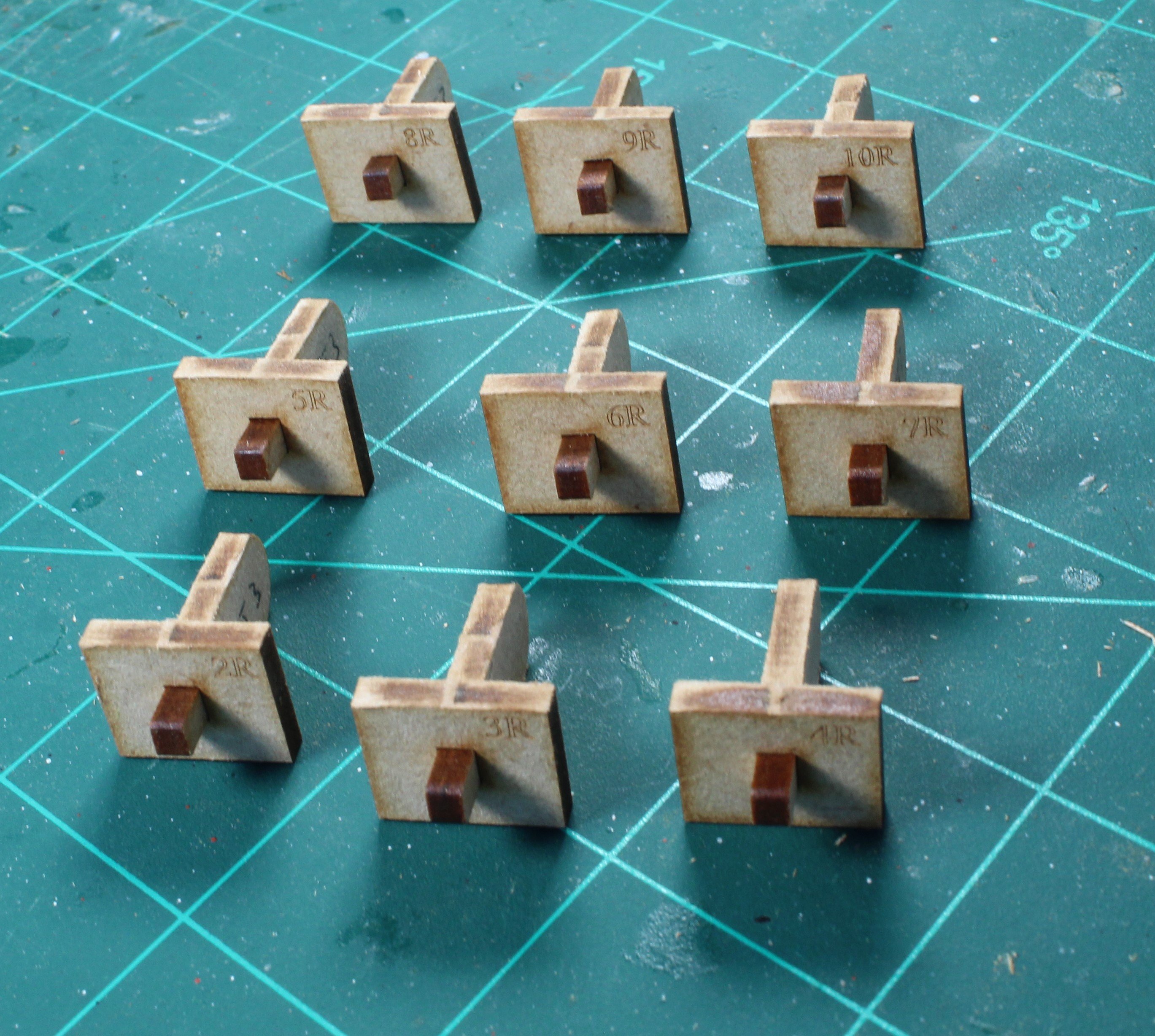
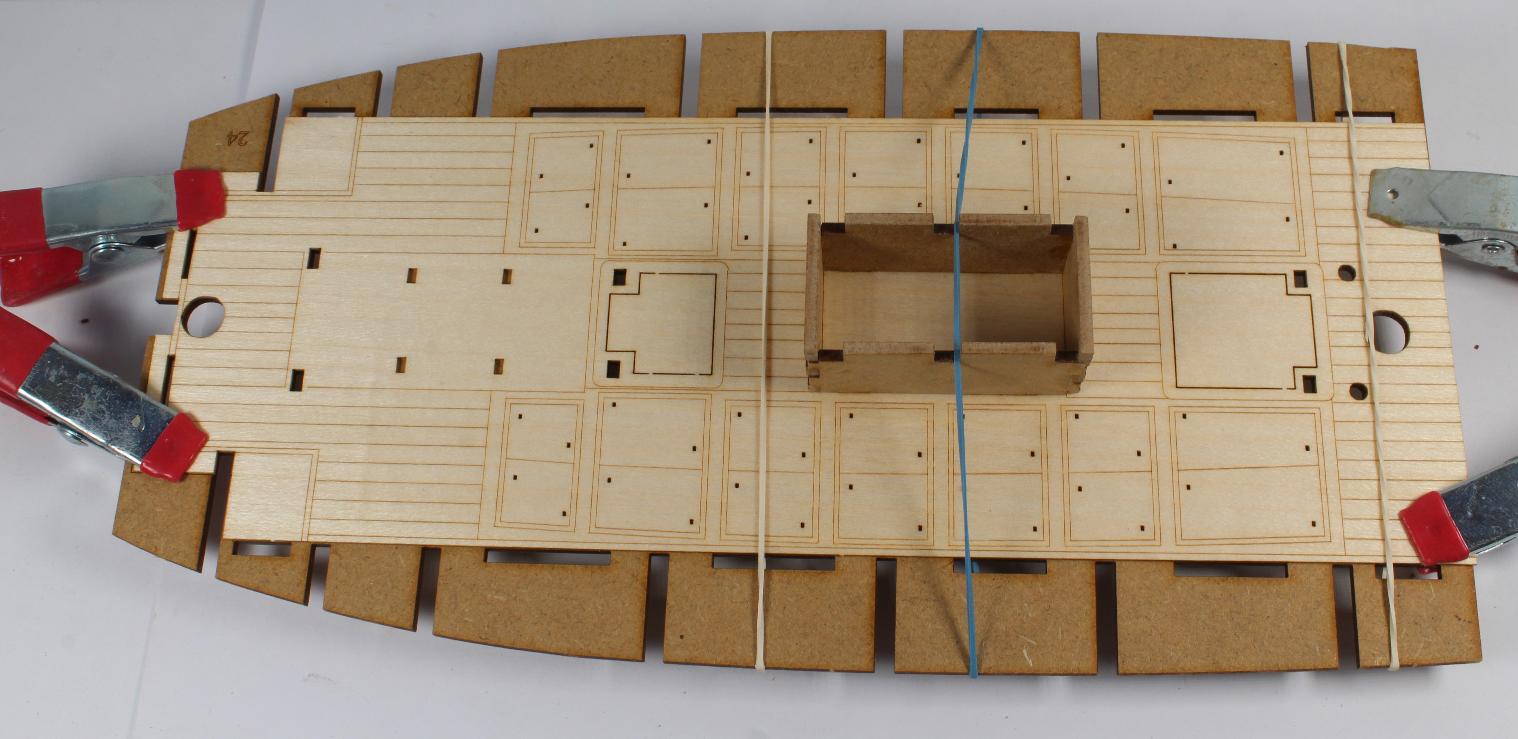
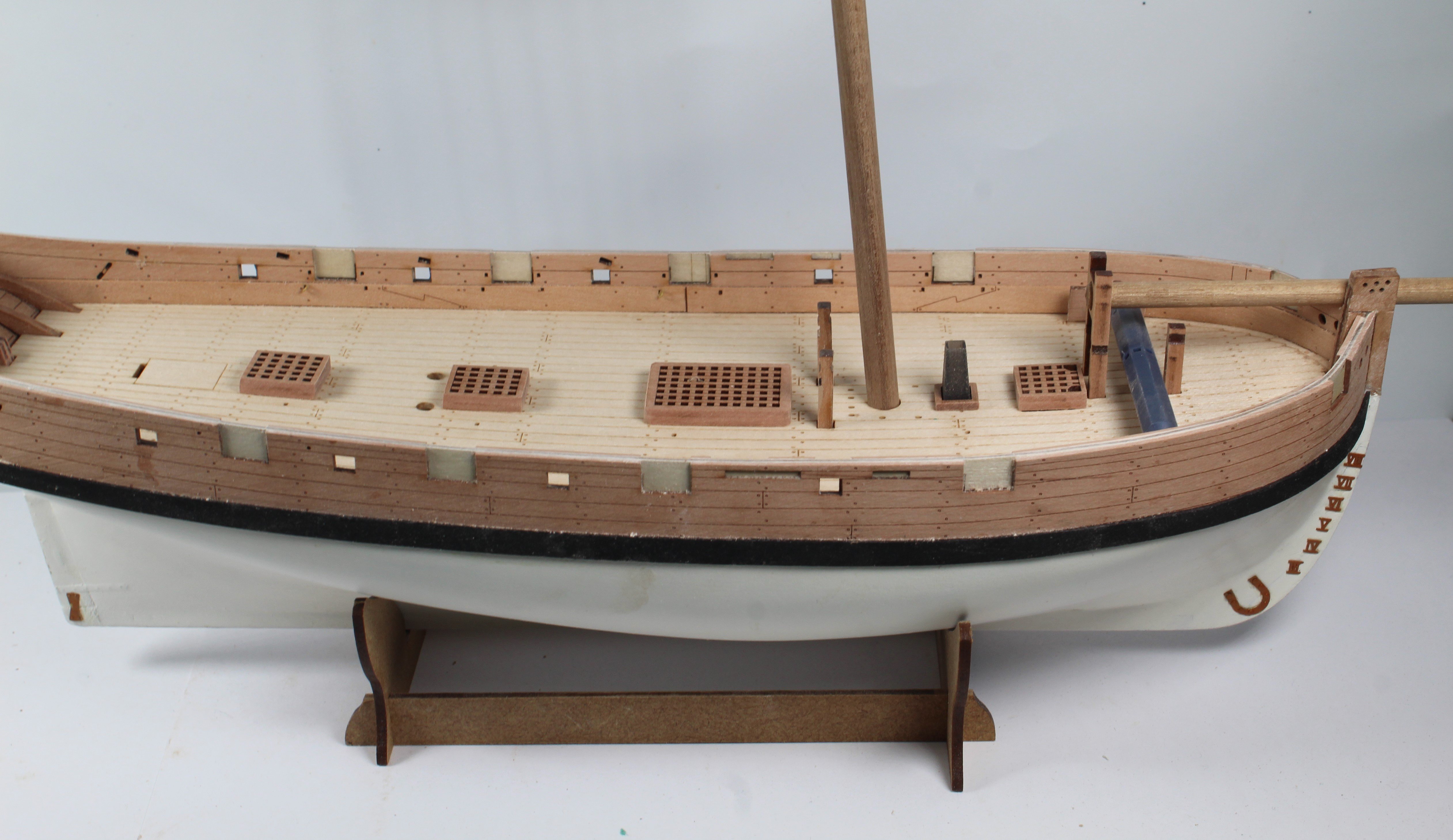
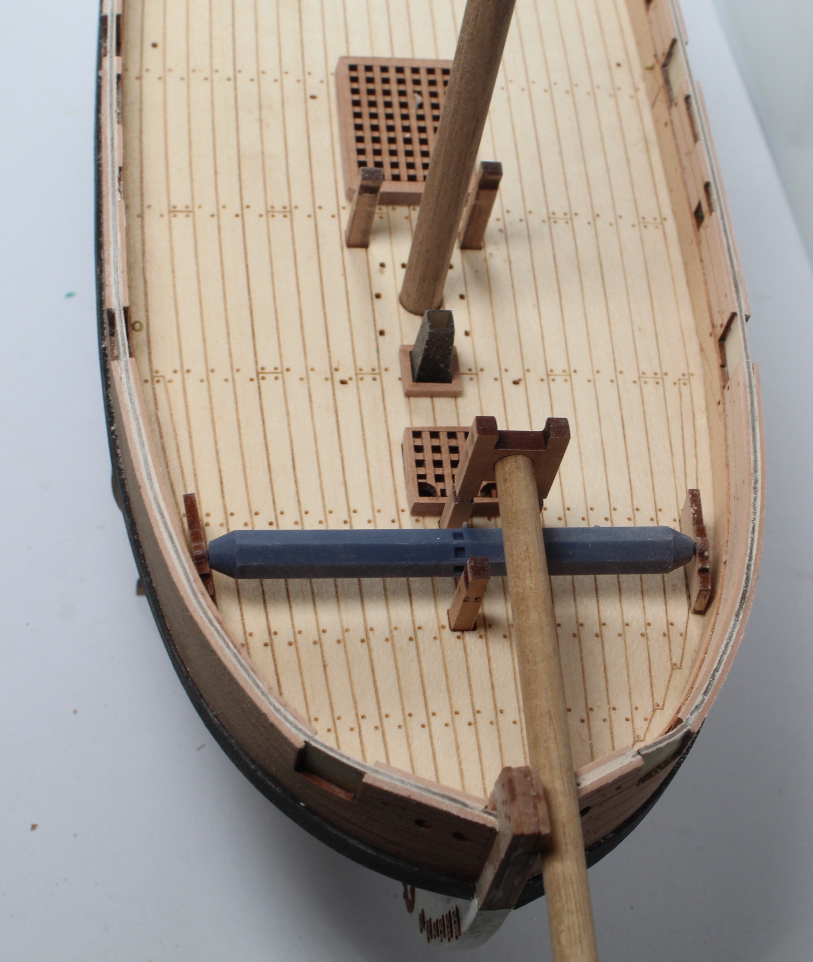
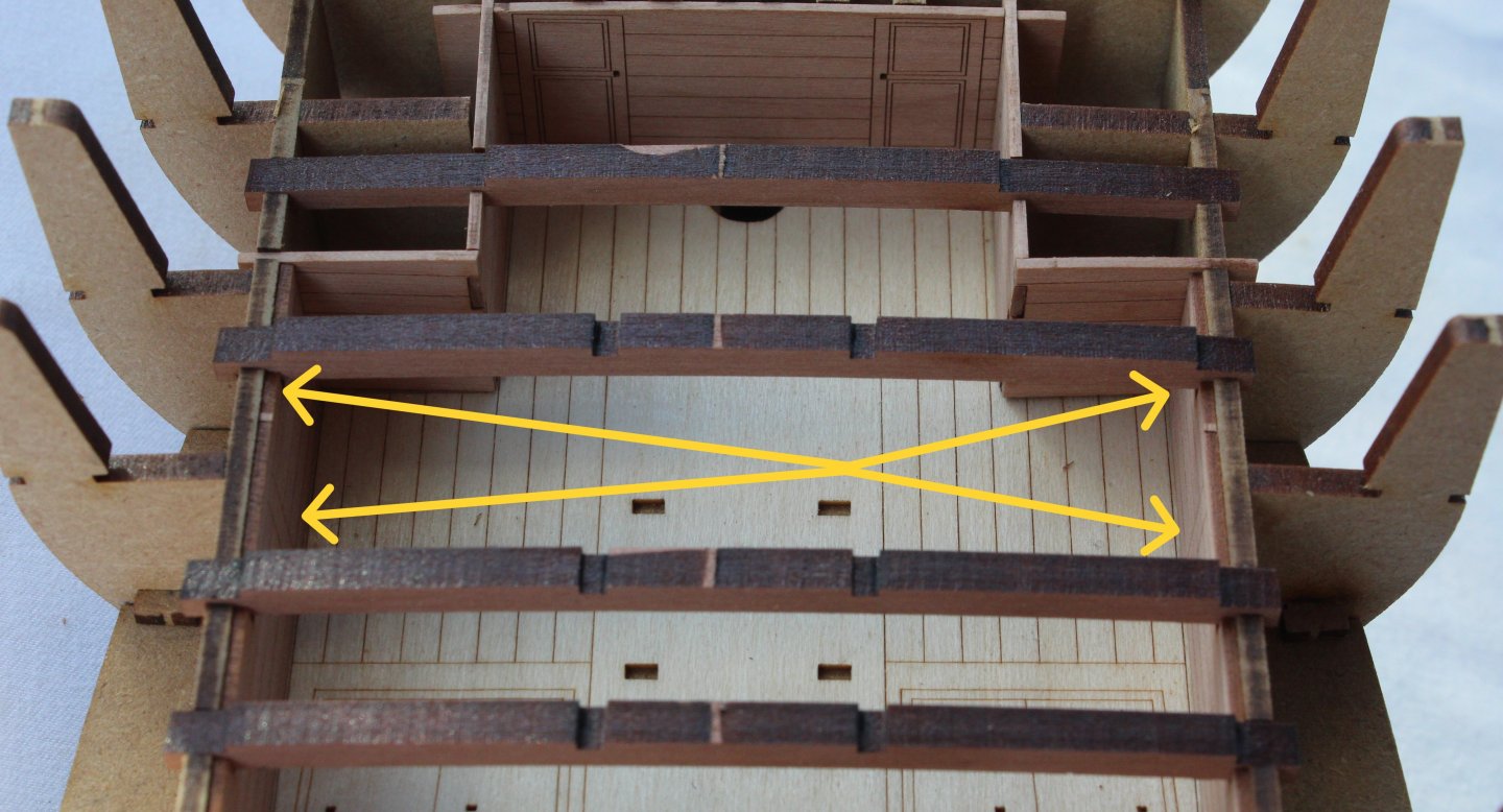
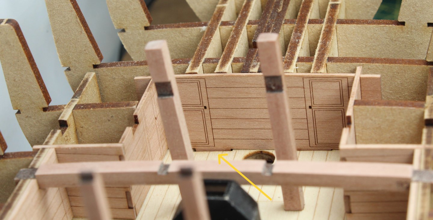
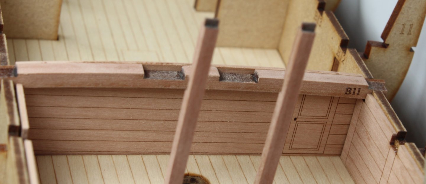
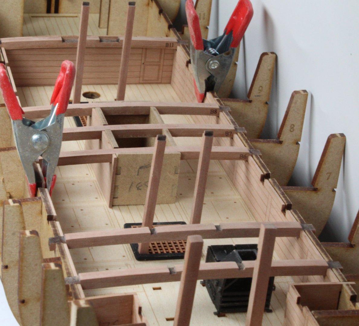
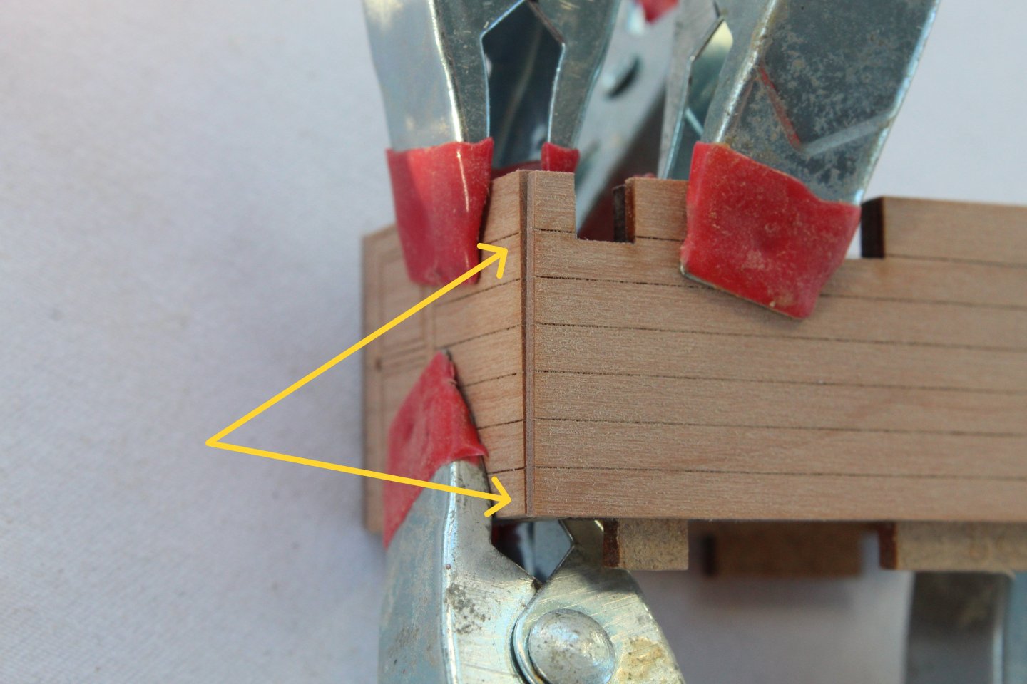
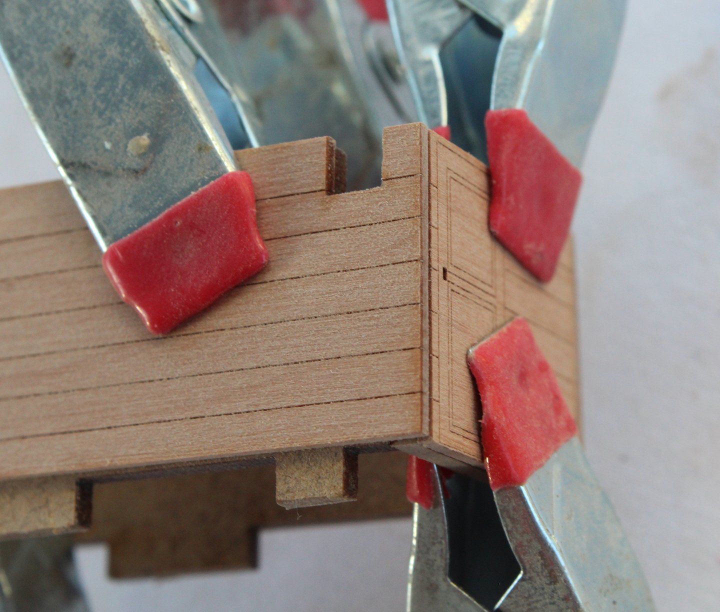
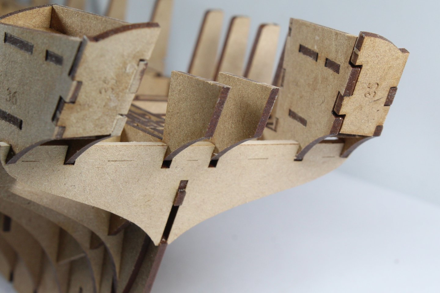
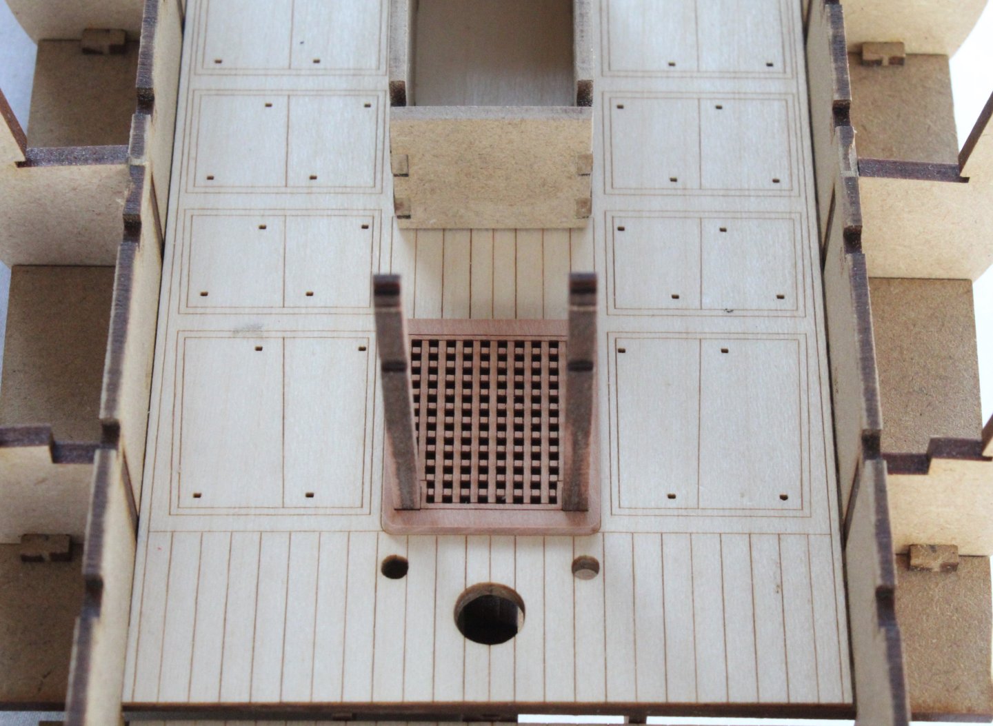
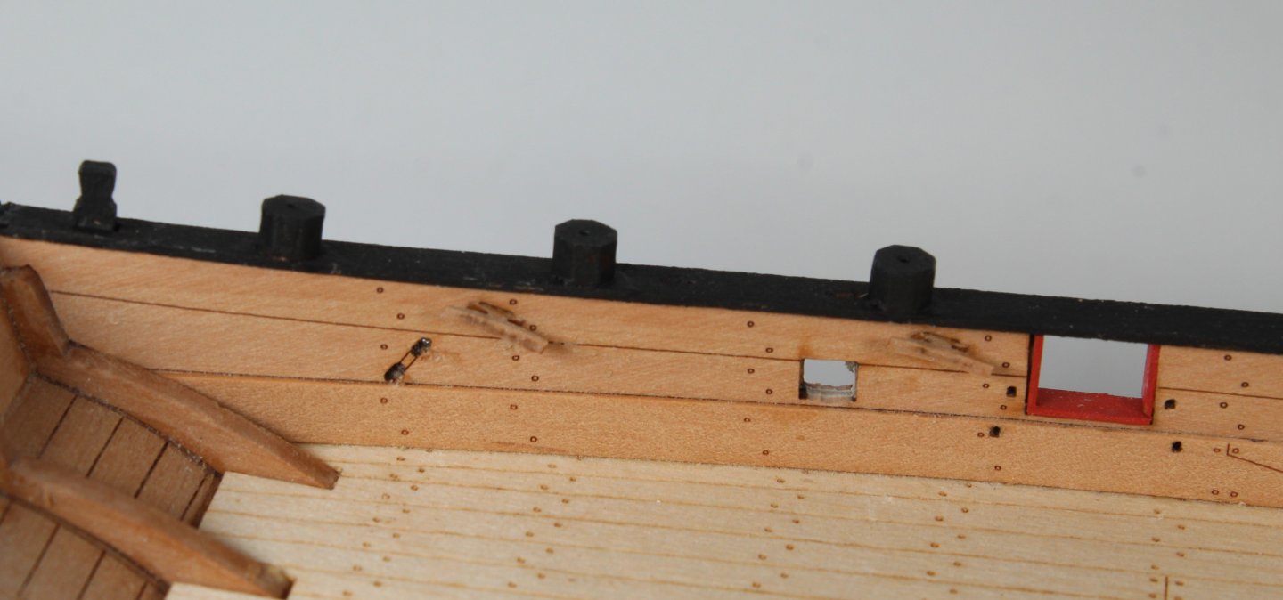
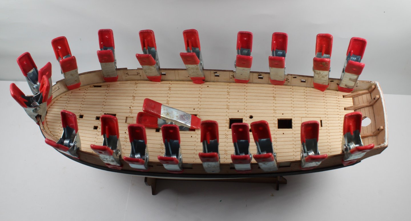
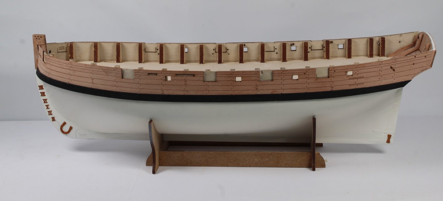
Spent the day looking at the next few build stages to see if there are any potential things that may need a bit of work. With the various side patterns clamped in place I did a trial fit of all the upper deck beams. I was very pleased that, with the exception of deck beams 2, 3 and 7, all the remaining deck beams were a perfect fit. This can be seen in the two photo below, as indicated by the yellow arrows. As can be seen in the next photo I am also checking the fit of the sail room side patterns with the beams in place. No problems were detected. There were no issue fitting deck beams 2, 3 and 7 when the side patterns were not fitted. The problem was solved when I lightly sanding the laser char from the side pattern deck beam slots using a narrow gauge 400-grit sanding stick. As can be seen in the next photo (yellow arrow) I am not totally happy with how the forward deck pattern is sitting. This is due to the addition of adding the two side cabin patterns. A little bit of fine adjustment will be required when these parts are installed to get patterns to sit flush. I decided to paint the frames of the deck gratings black. After taping the central grating areas I applied a coat of wipe on varnish (WOP). Once that had fully dried I applied two coats of matt black paint. I am very pleased with the end result and they look very good. They are test fitted in the next two photos. You will also note I have started to clean the laser char from the top of the deck beams and bitts. The mid section deck pattern, which sits right behind deck beam 11, is a very good fit. The following photo shows the lower deck with some of the deck beams and deck items dry fitted. Even at this very early stage the Harpy is certainly an impressive looking model and I think it will look even better once the outer decorative patterns have been painted. I am thinking of using a light grey, AK11817 RLM65 rather than a flat red colour. Next I looked at test fitting the sail room outer patterns. As can be seen in the next two photos there is a bit of work required to get a nice neat finish, as they are not flush fitting. After a little bit of sanding to remove the excess tab material the sail room patterns were a much better fit, as can be seen in the next photo.


- 241 replies
-
- 17
-
-
- Vanguarrd Models
- Harpy
- (and 1 more)
-
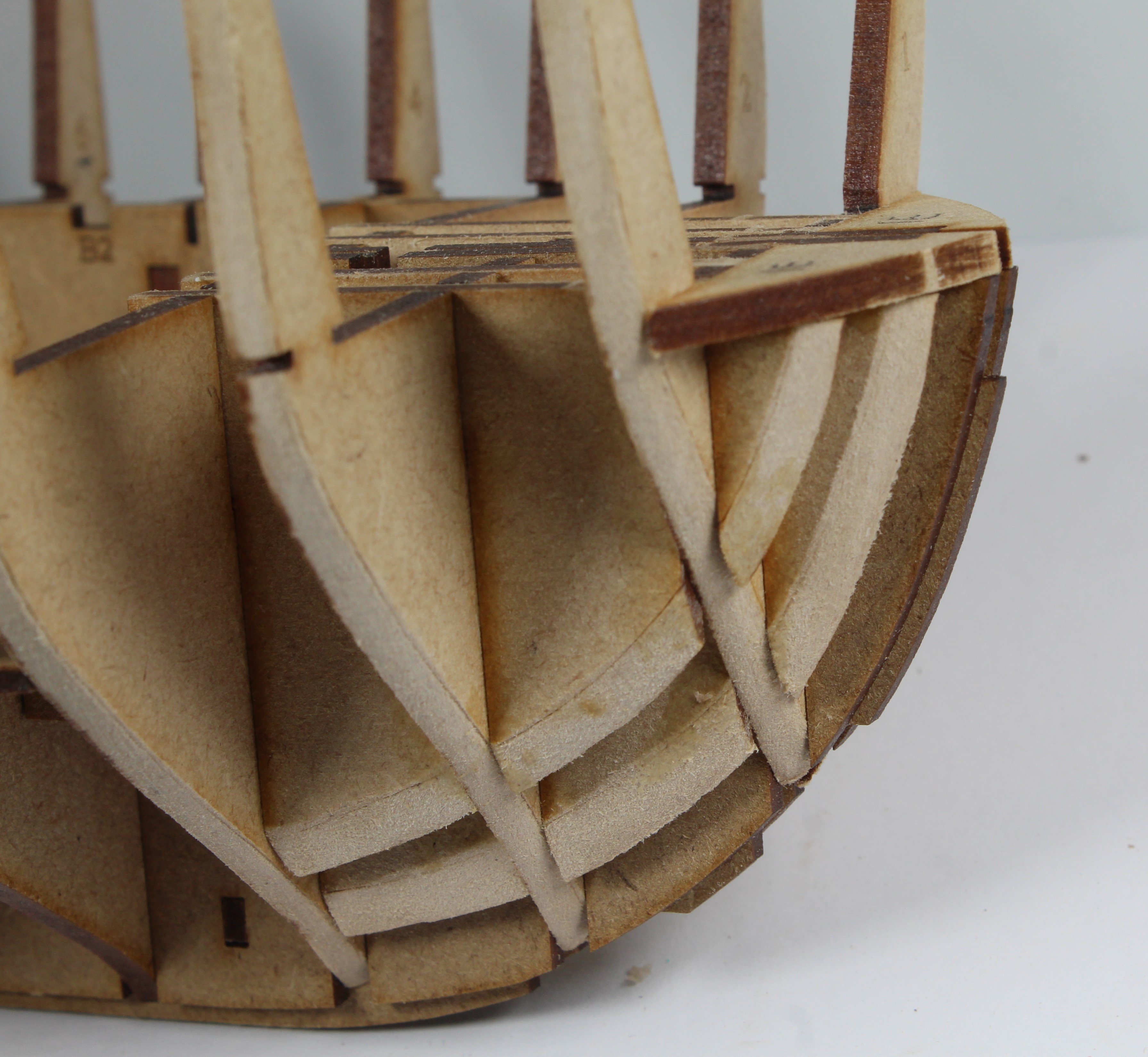
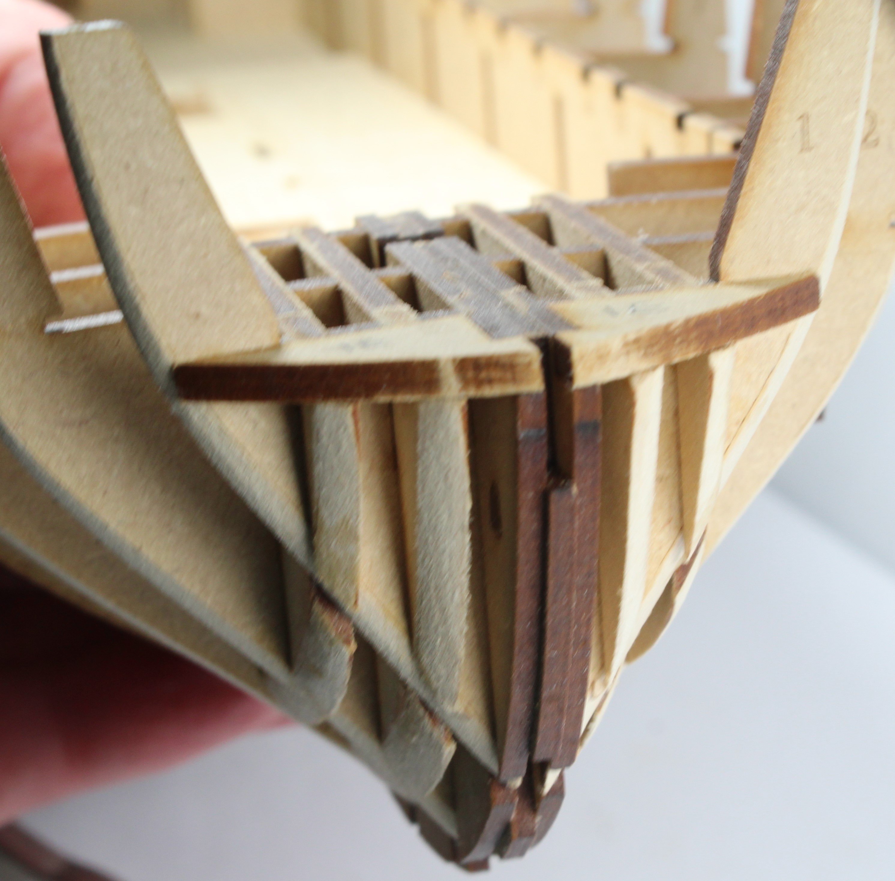
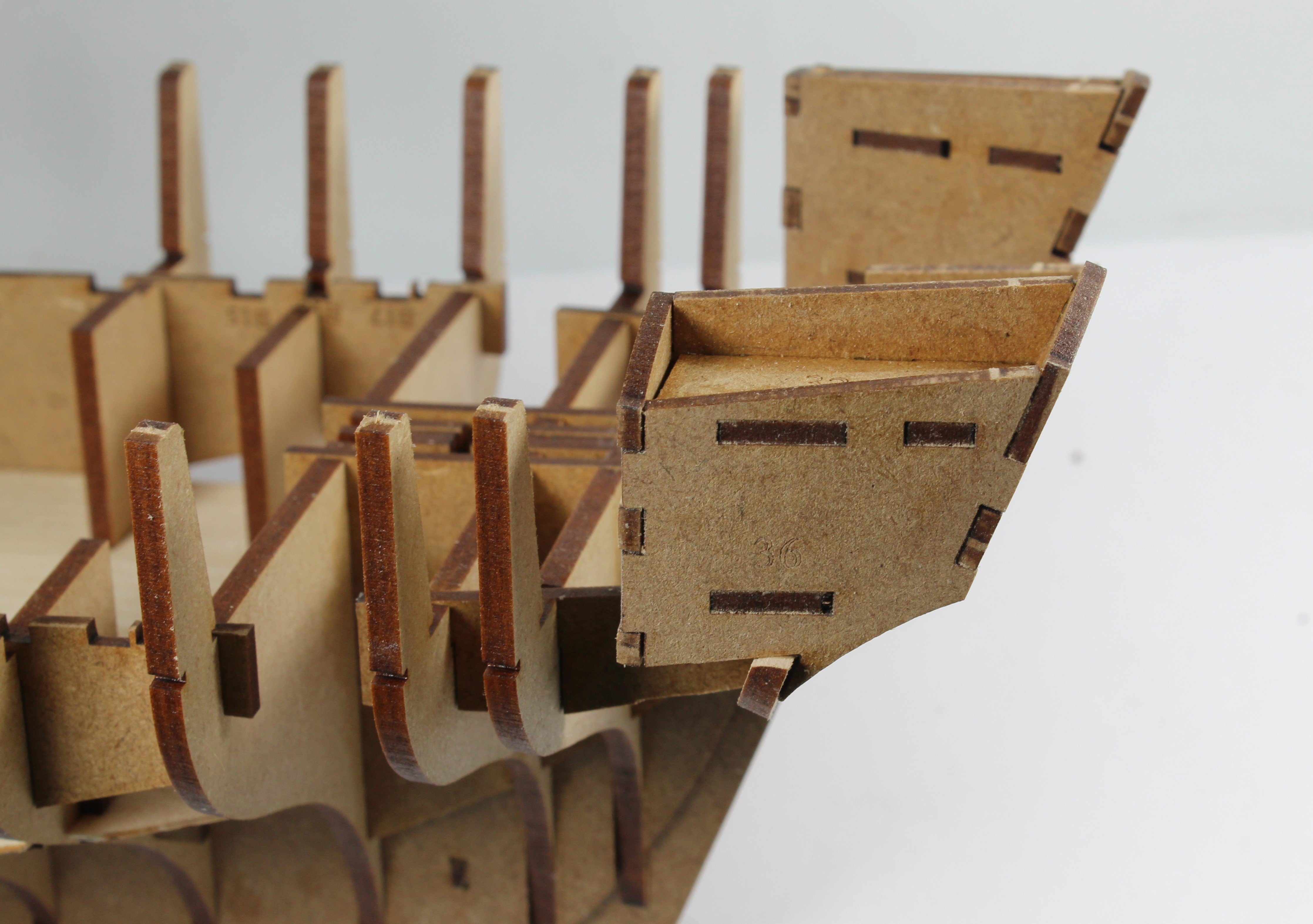
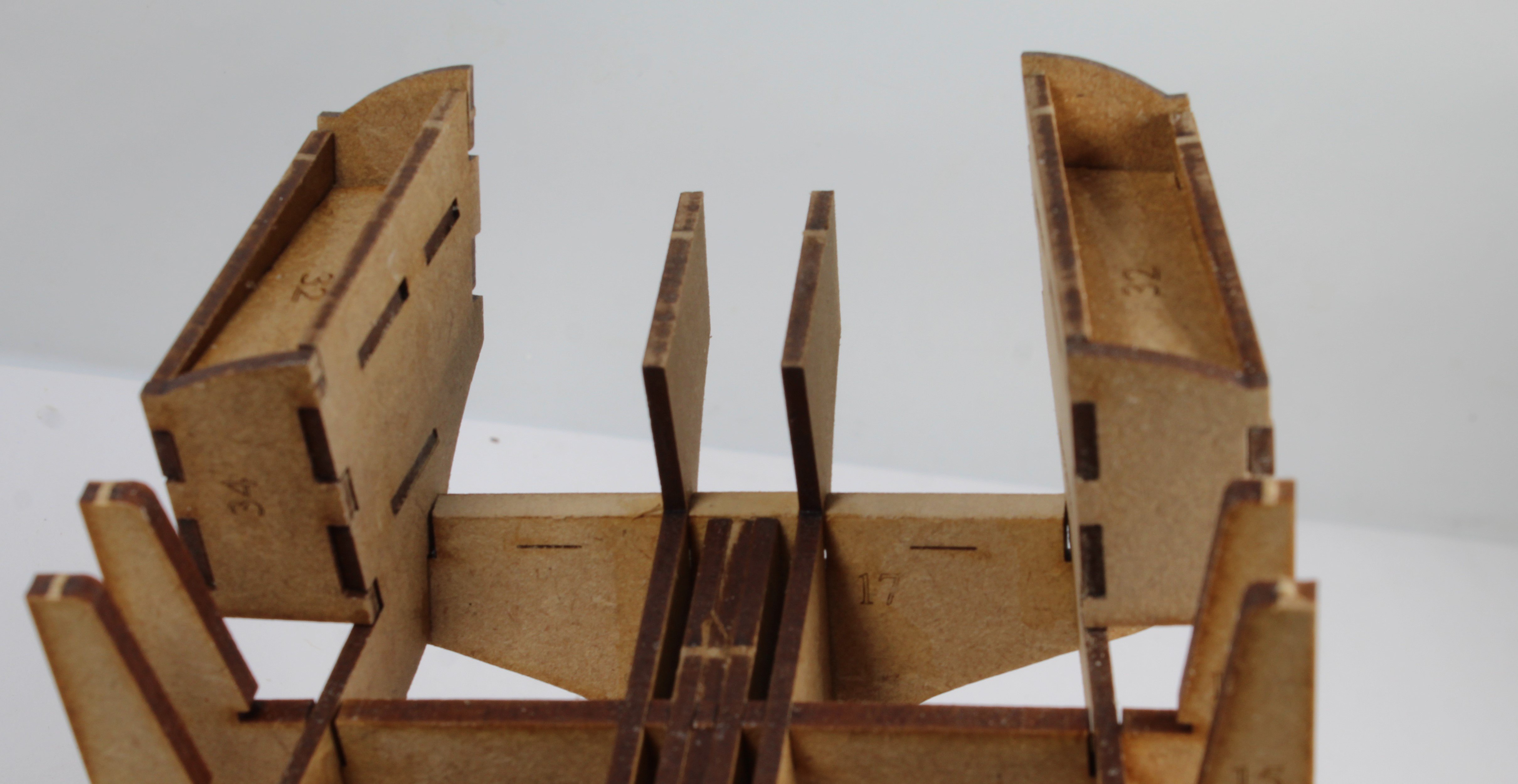
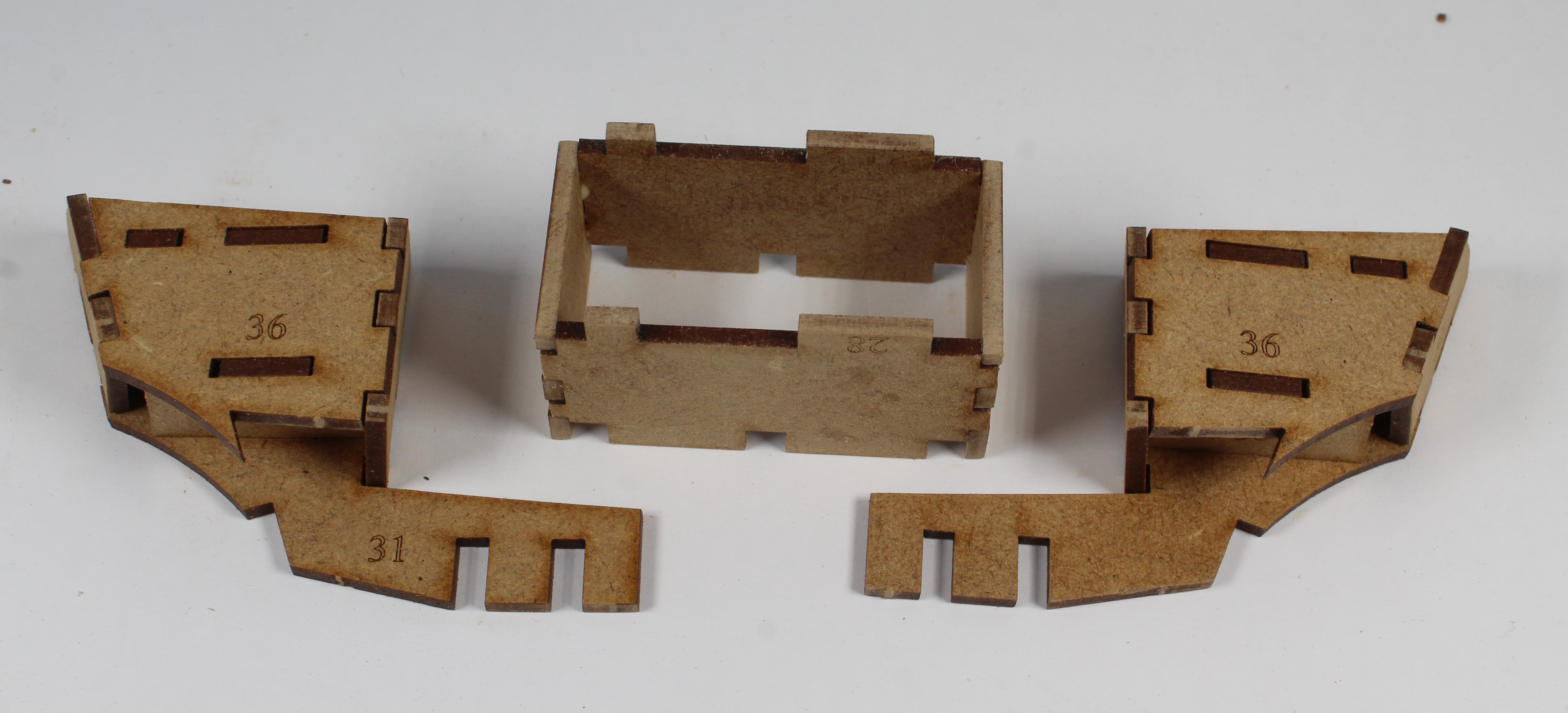
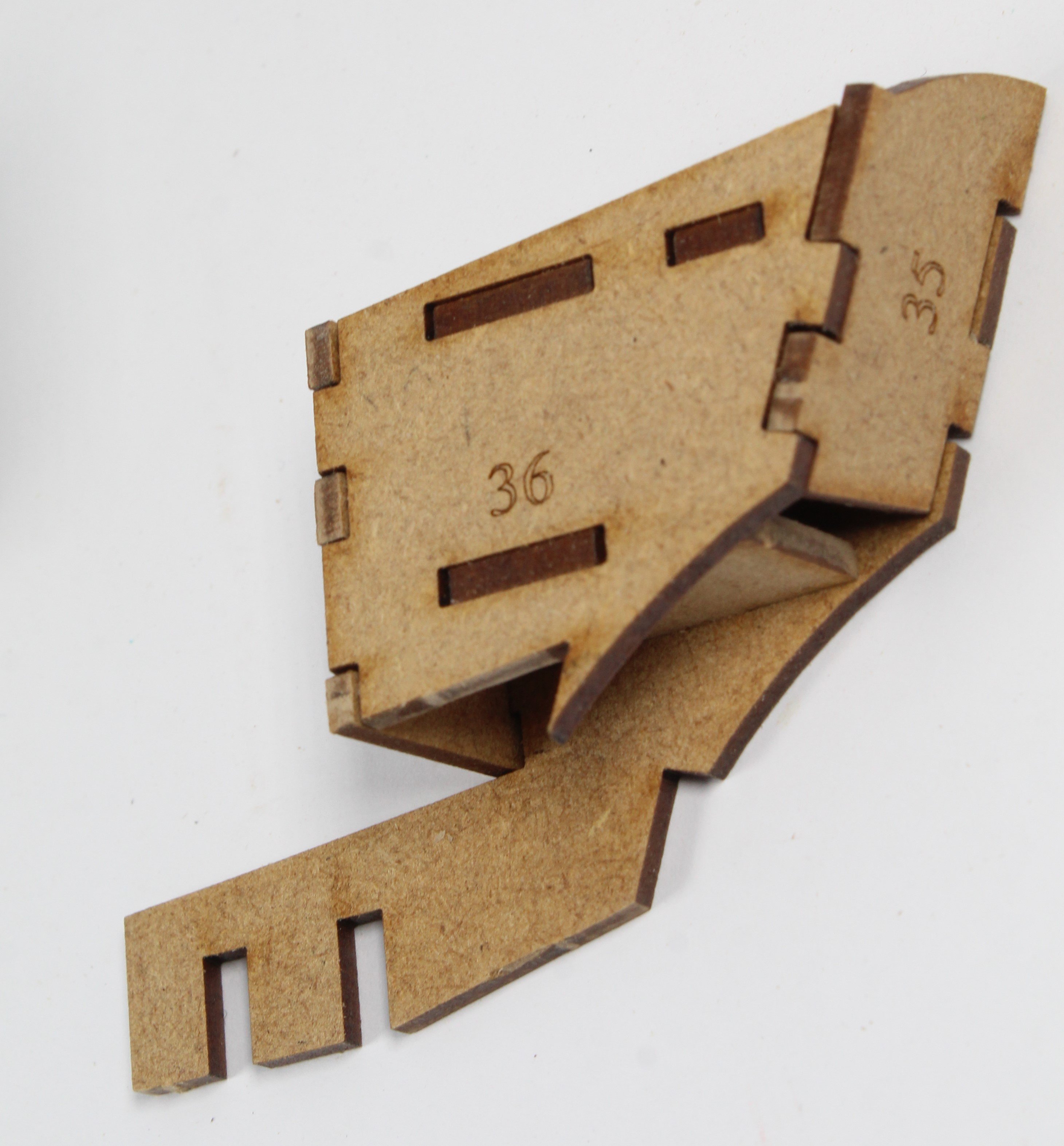
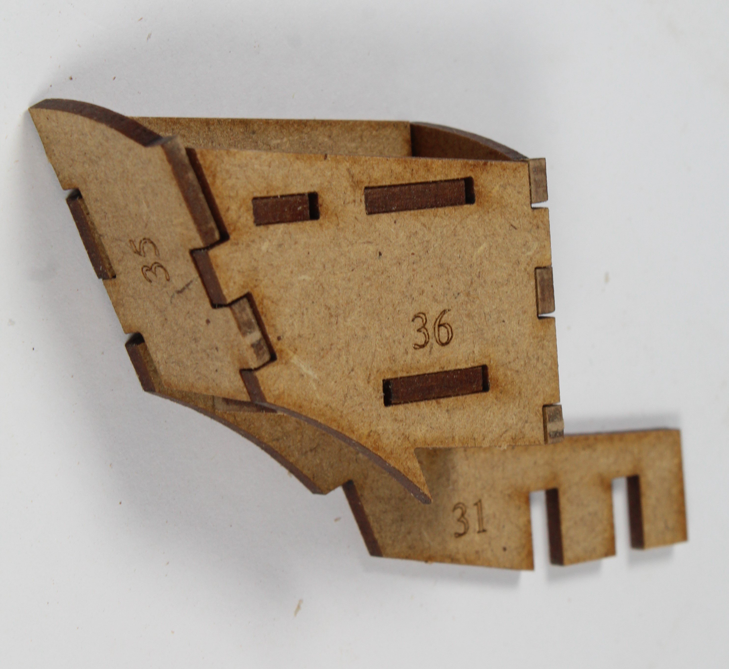
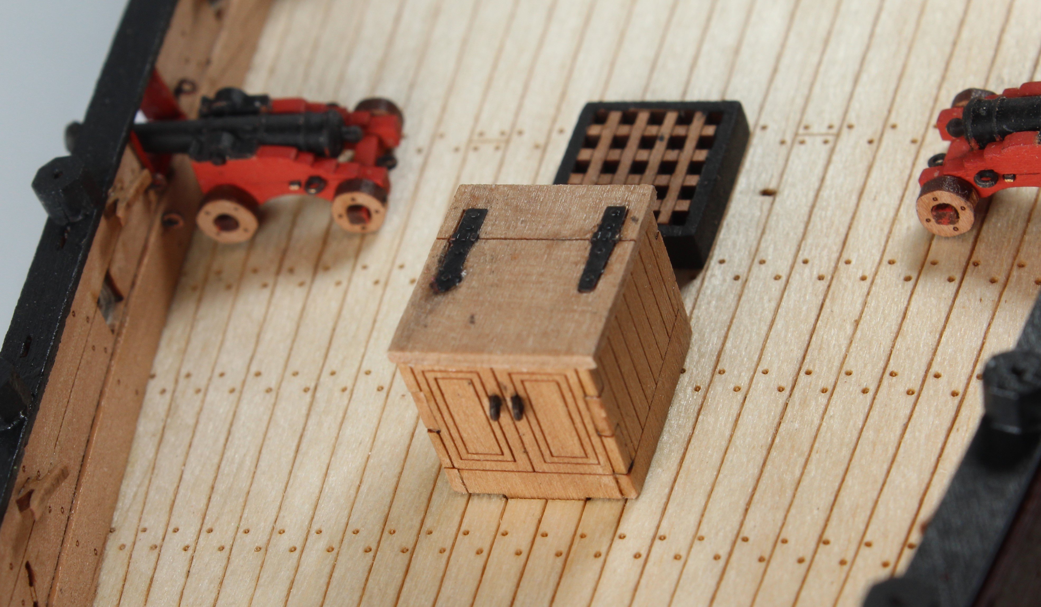
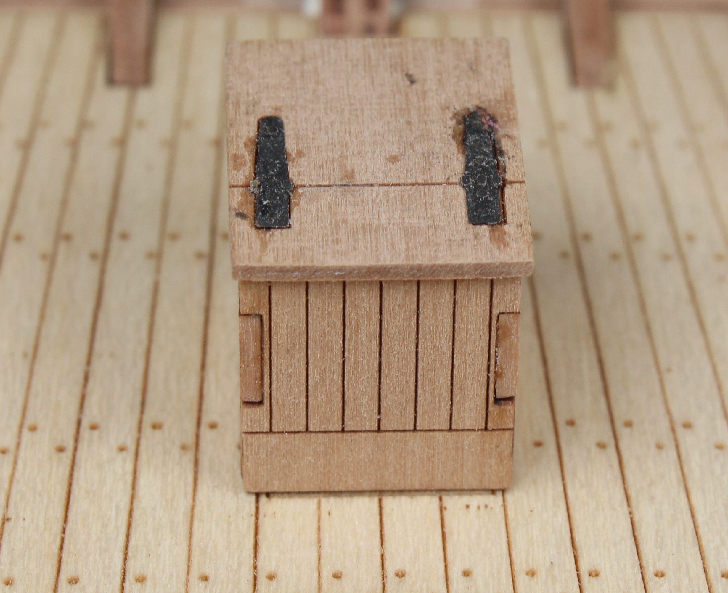
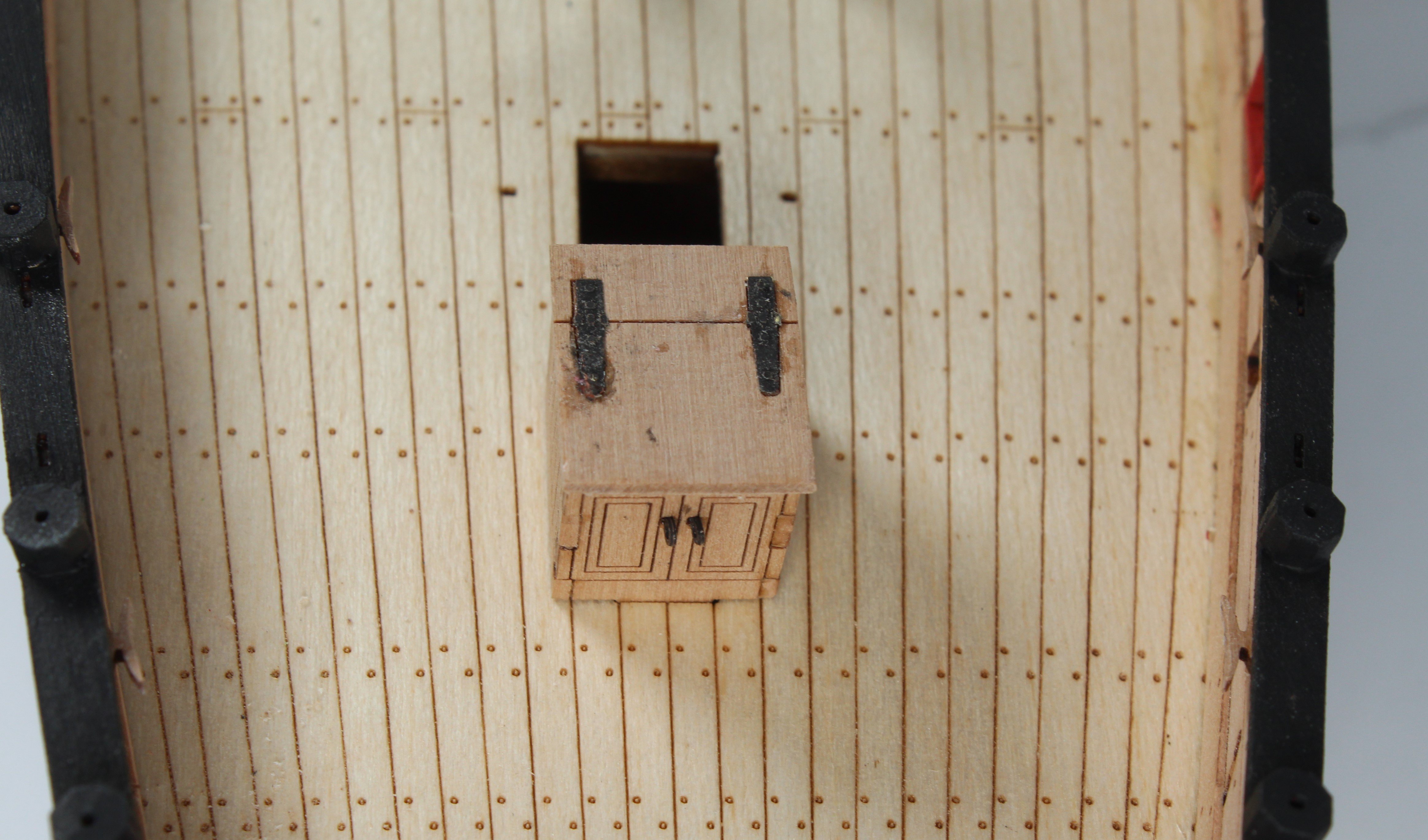
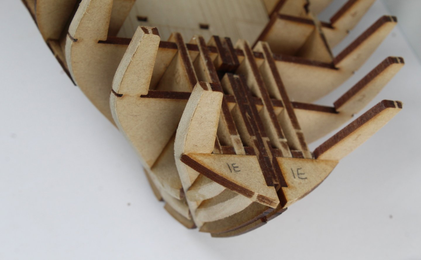
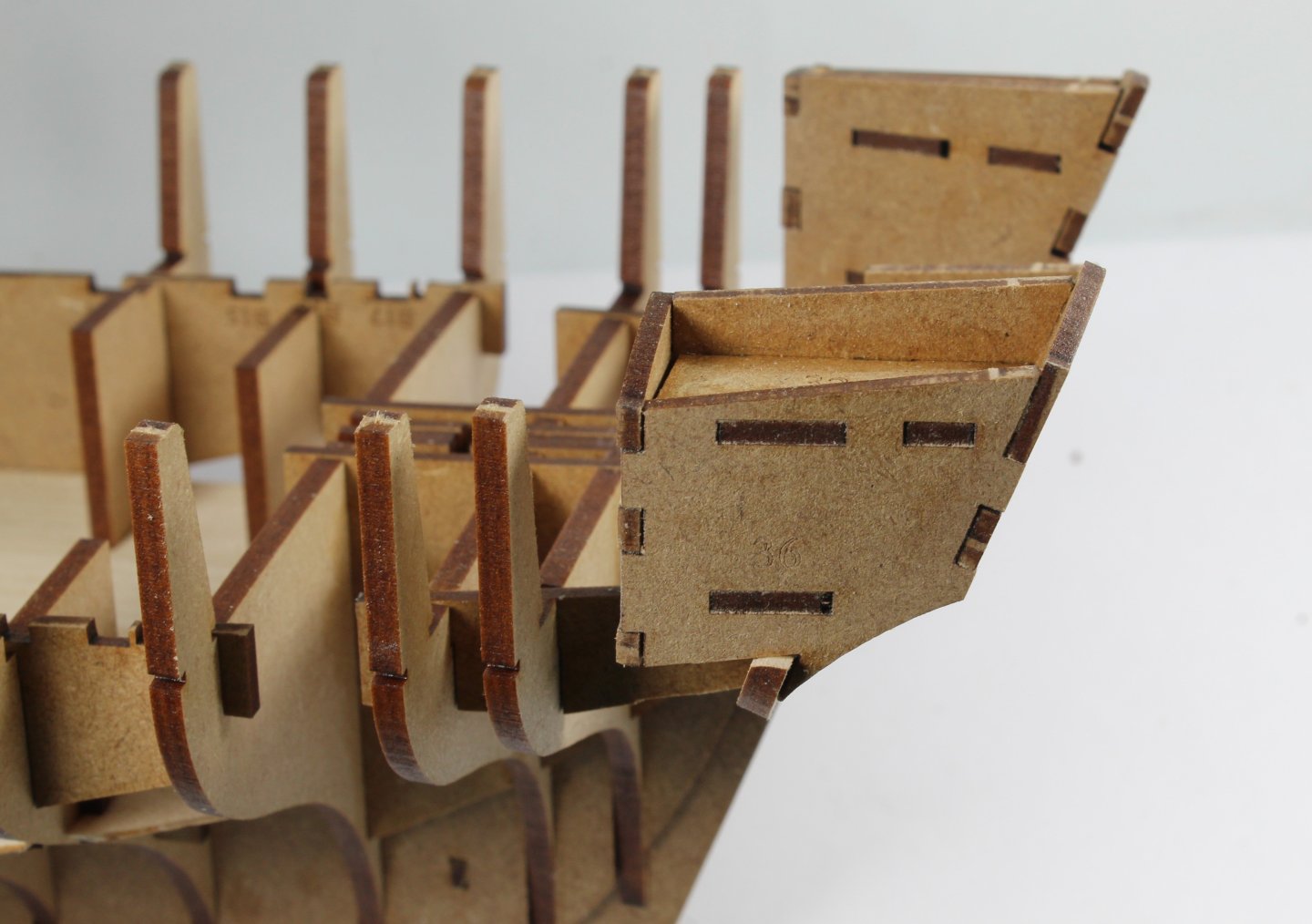
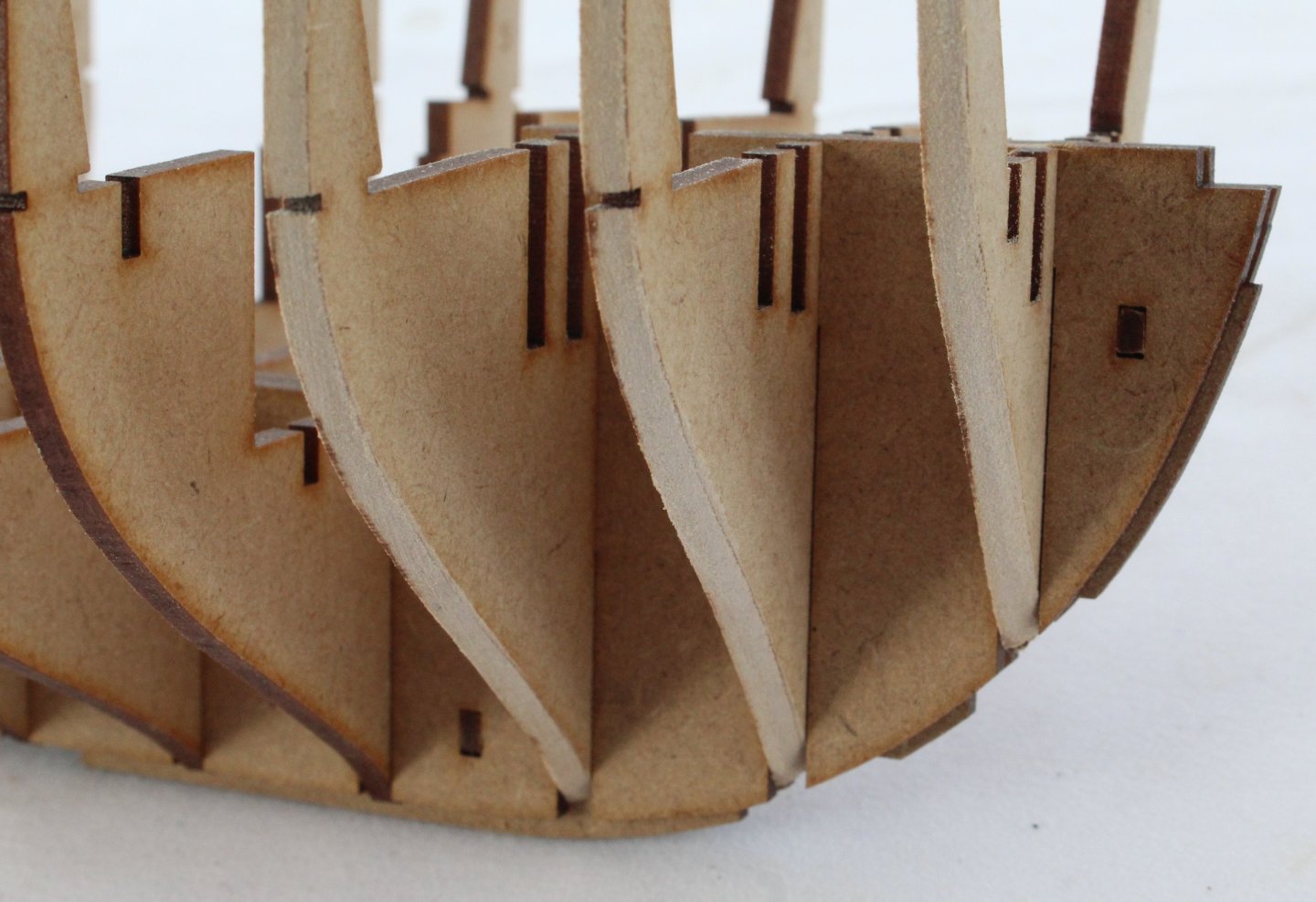
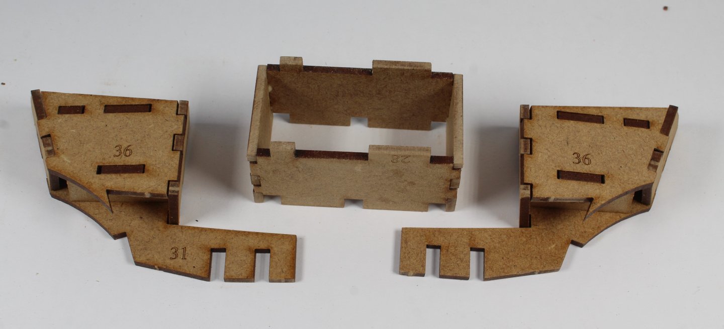
Today was a day looking after one our young grandkids so my time in the shipyard was very limited to about 20 minutes. That said that was enough time to do a few tasks. I started by pre-fairing the four bow planking patterns to the laser etched guide lines and then they were slotted in to place, noting these parts were glued. Once that was done the two top bow planking patterns were glued in place. Moving swiftly on, after a quick dry fit check the following stern patterns were glued in place, in the following order a) 2 off stern frame patterns (inner) b) Bulkhead 17, after it the top edge had been beveled to the laser etched guide line. c) 2 off stern frame outer patterns, complete with the rear cabin assemblies. Once that was done the hull was turned upside down and diluted Titebond wood glue was brushed in all the deck and bulkhead joints. The hull will now be left overnight to allow plenty of time for the glue to fully cure. According to the plans the next task will be to add the various internal panels. I will have to put this on the back burner as I have to pick up my order of sander sealer on Monday from a local supplier, as I intend to paint these patterns before they are fitted. Also I plan to use same hinge and door handles which I have ordered from Syren (USA). The order has been shipped to the UK but I expect it will probably take a week or two before the parts get delivered. There are plenty of other jobs I can do in the meantime.


- 241 replies
-
- 13
-
-
- Vanguarrd Models
- Harpy
- (and 1 more)
-
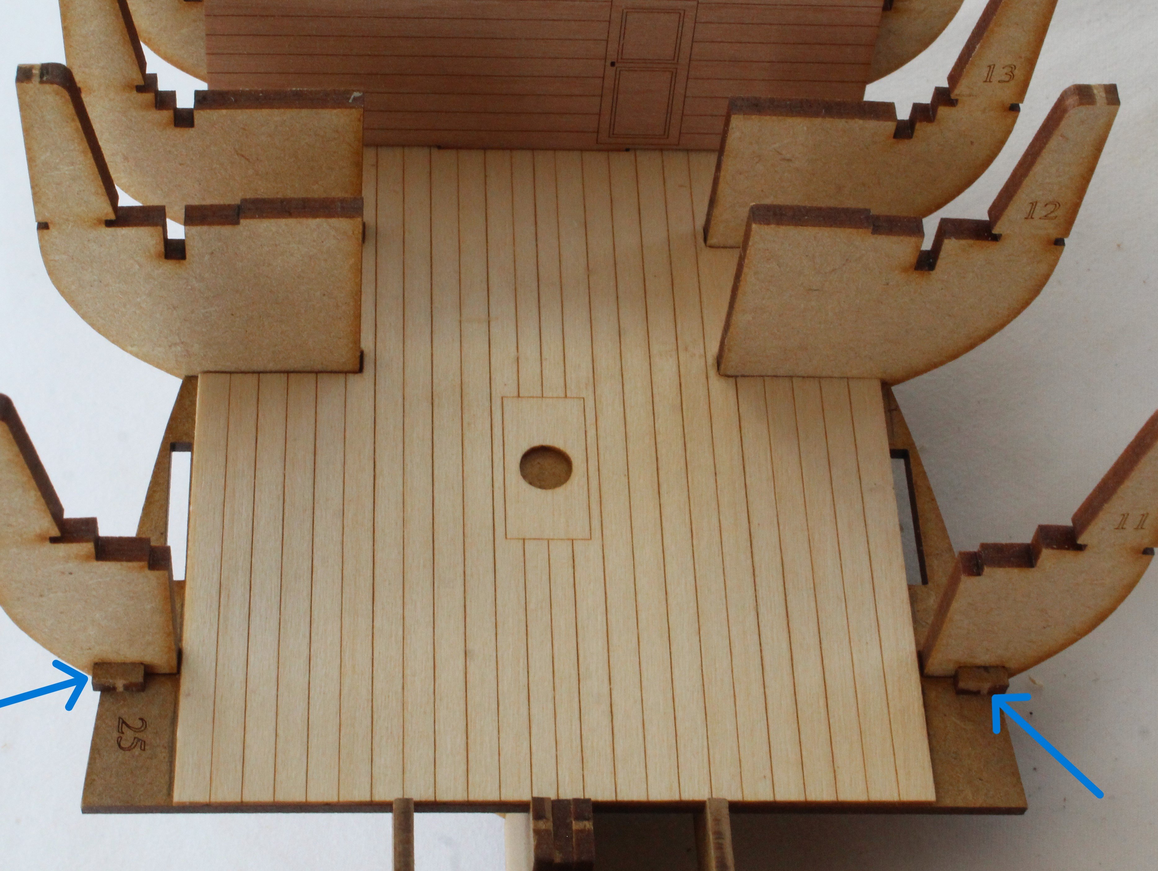
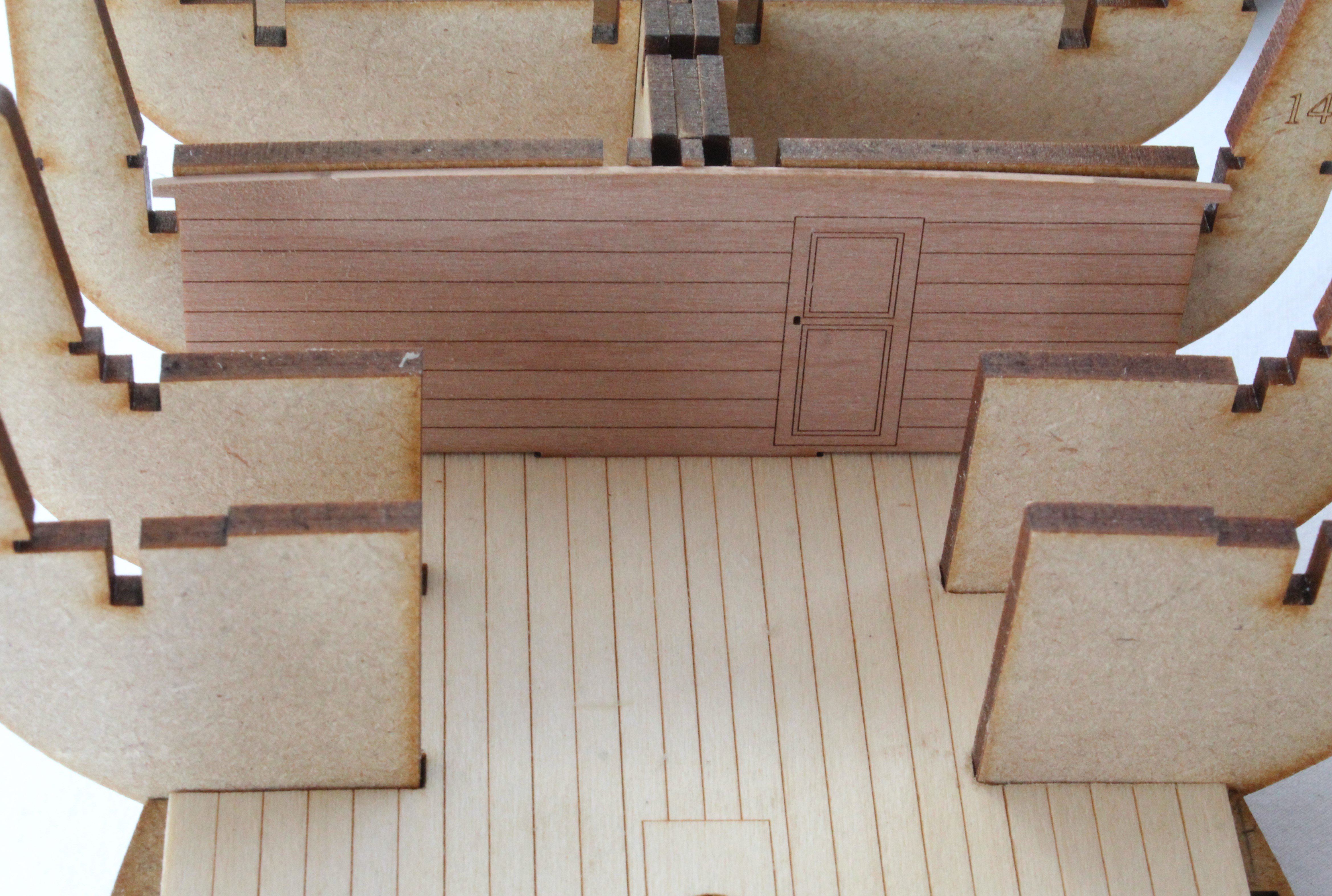
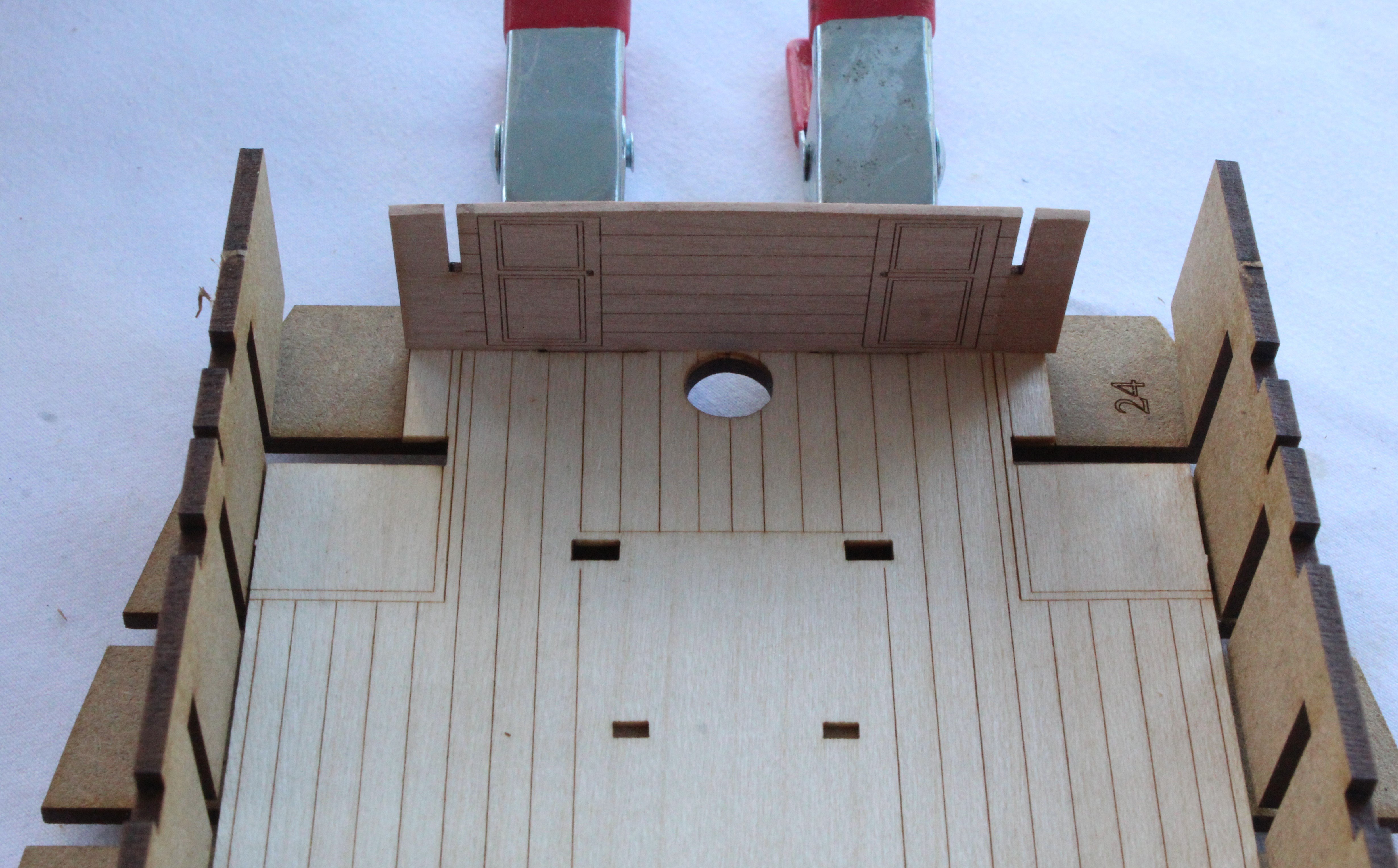
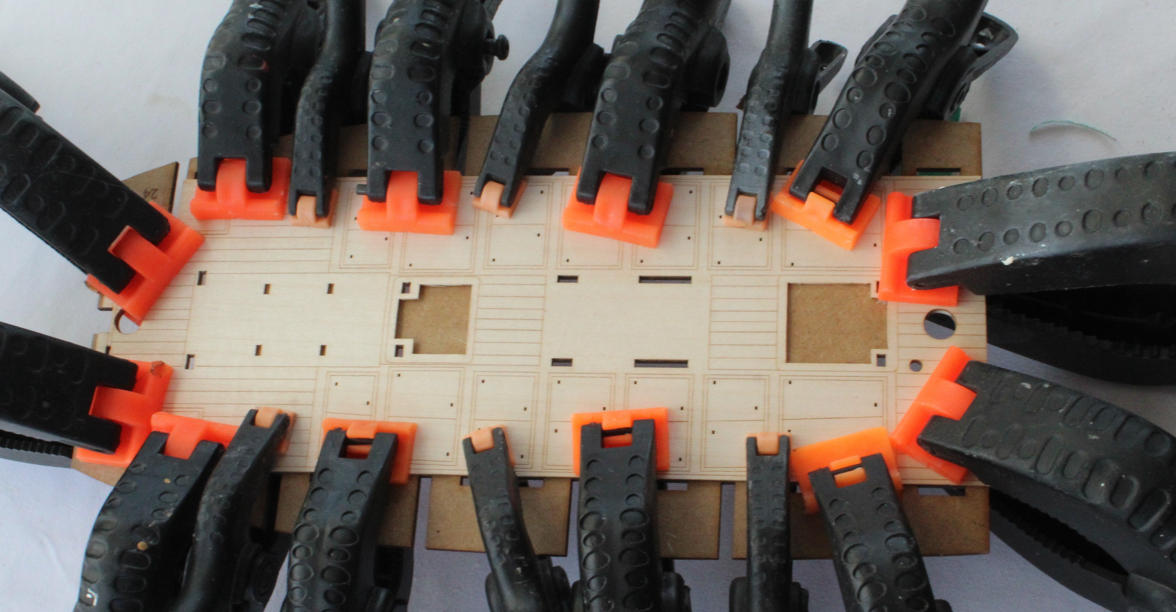
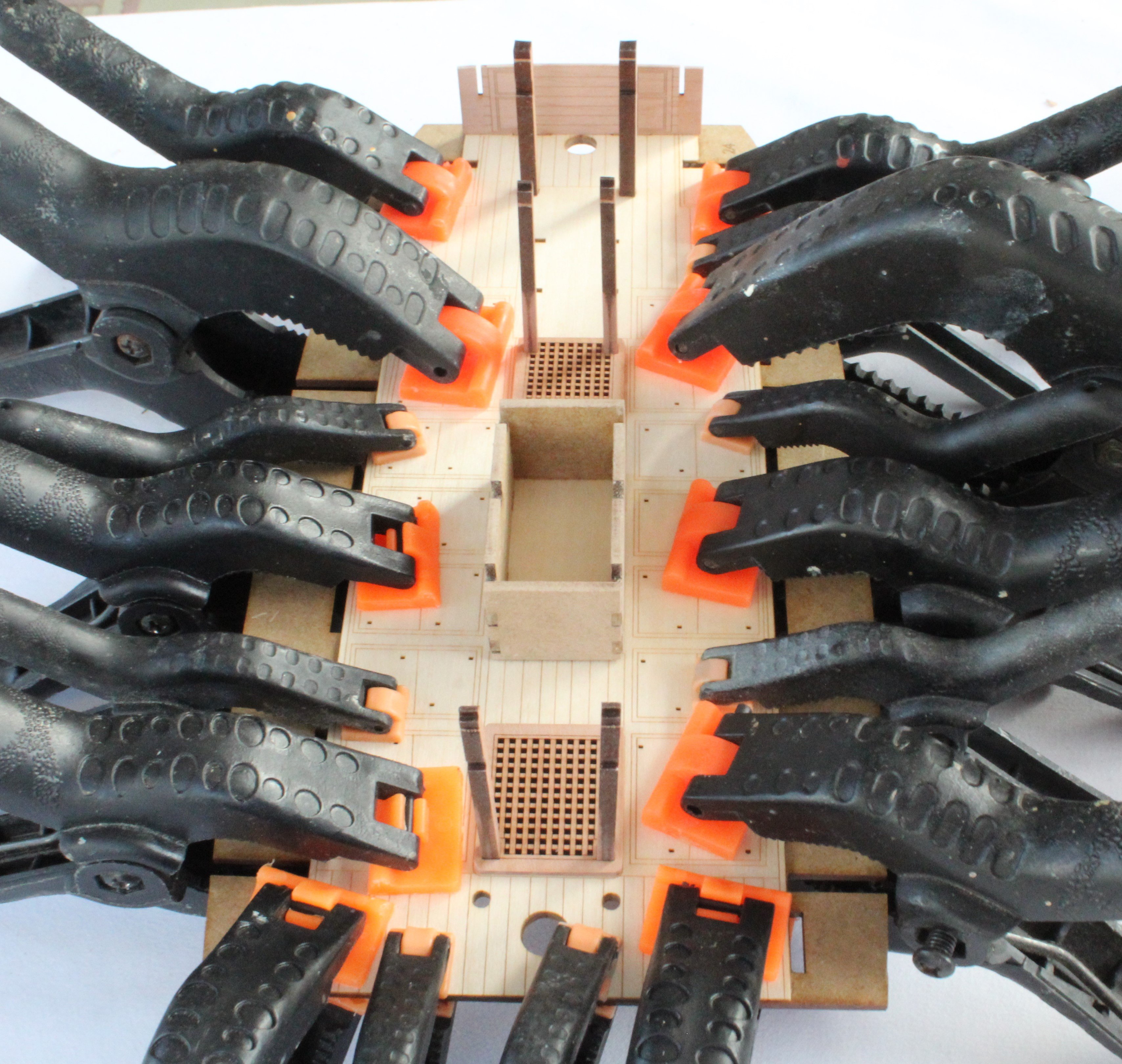
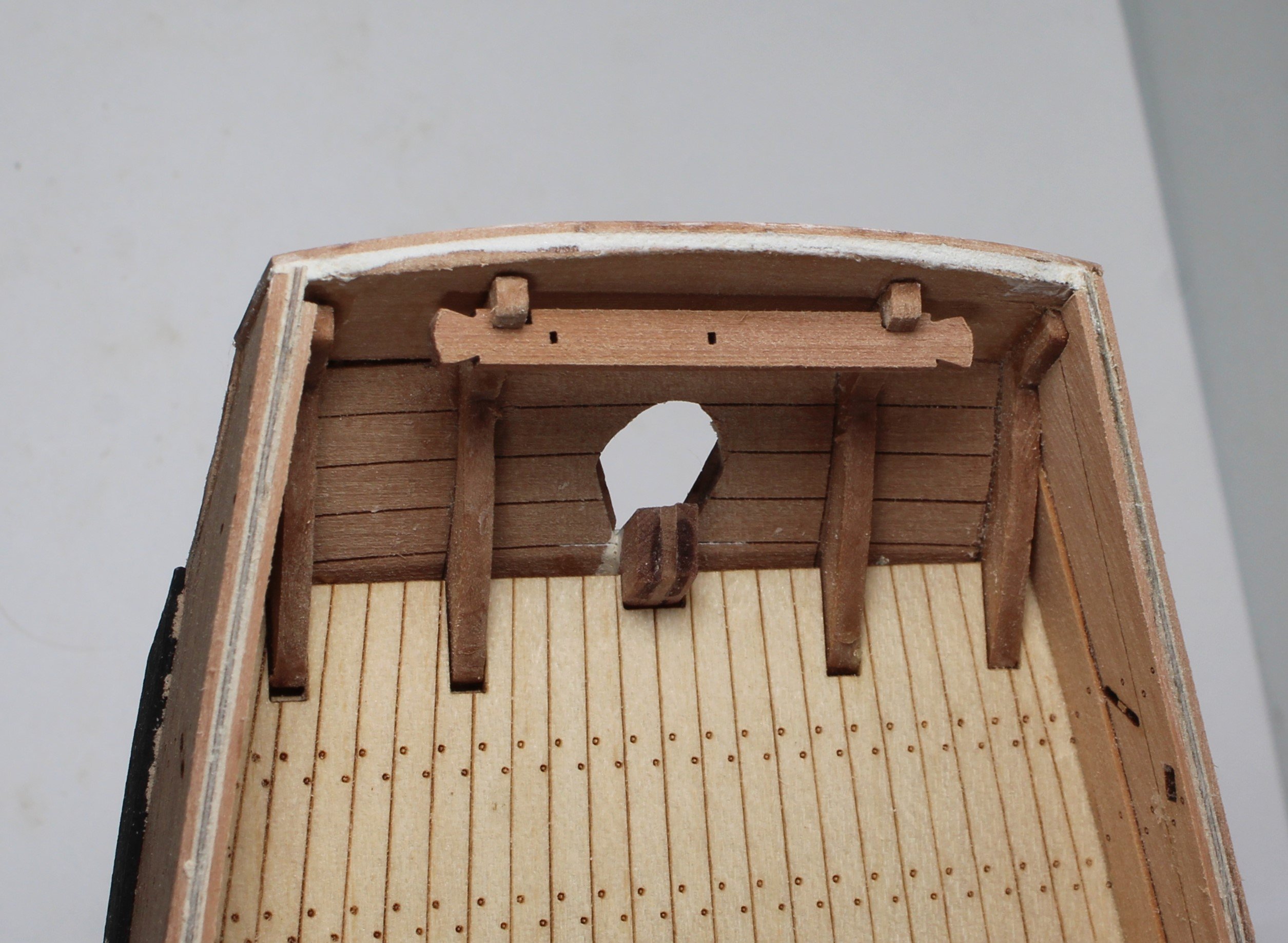
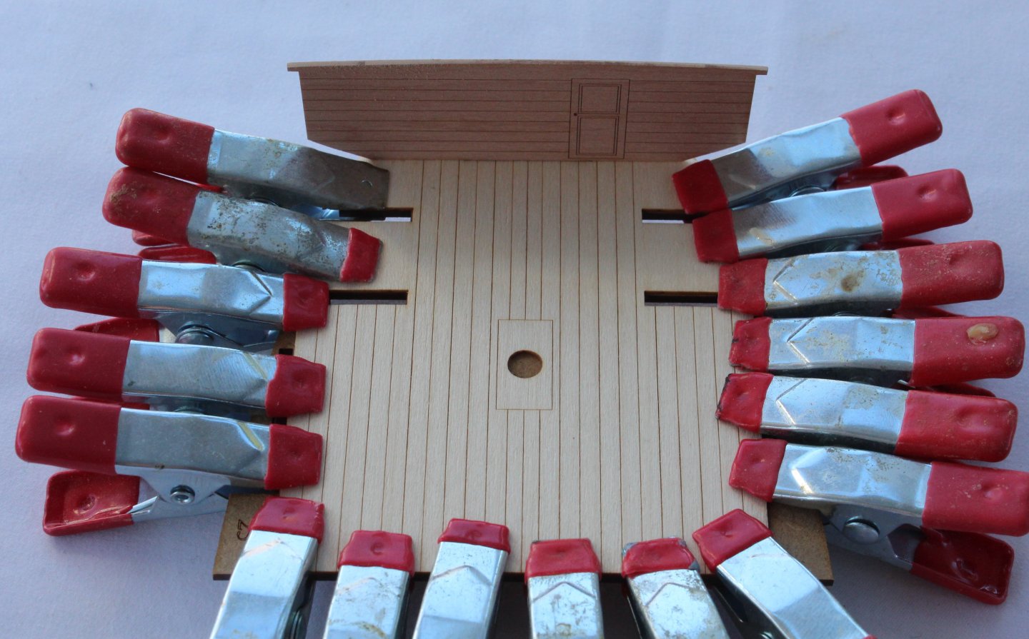
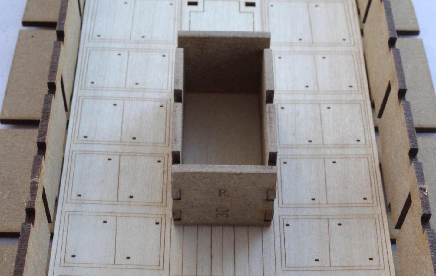
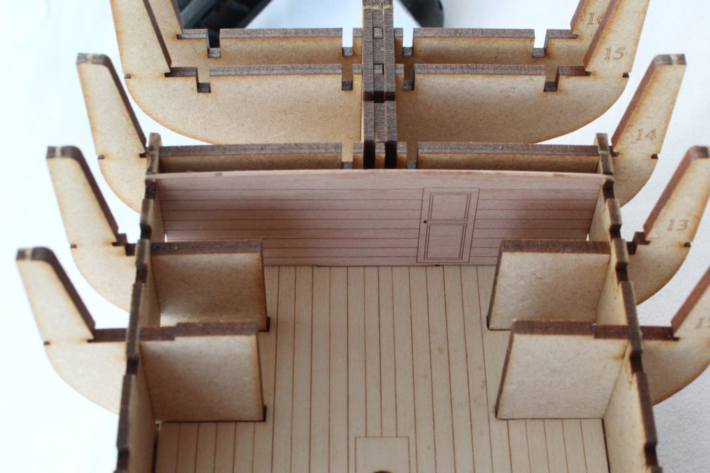
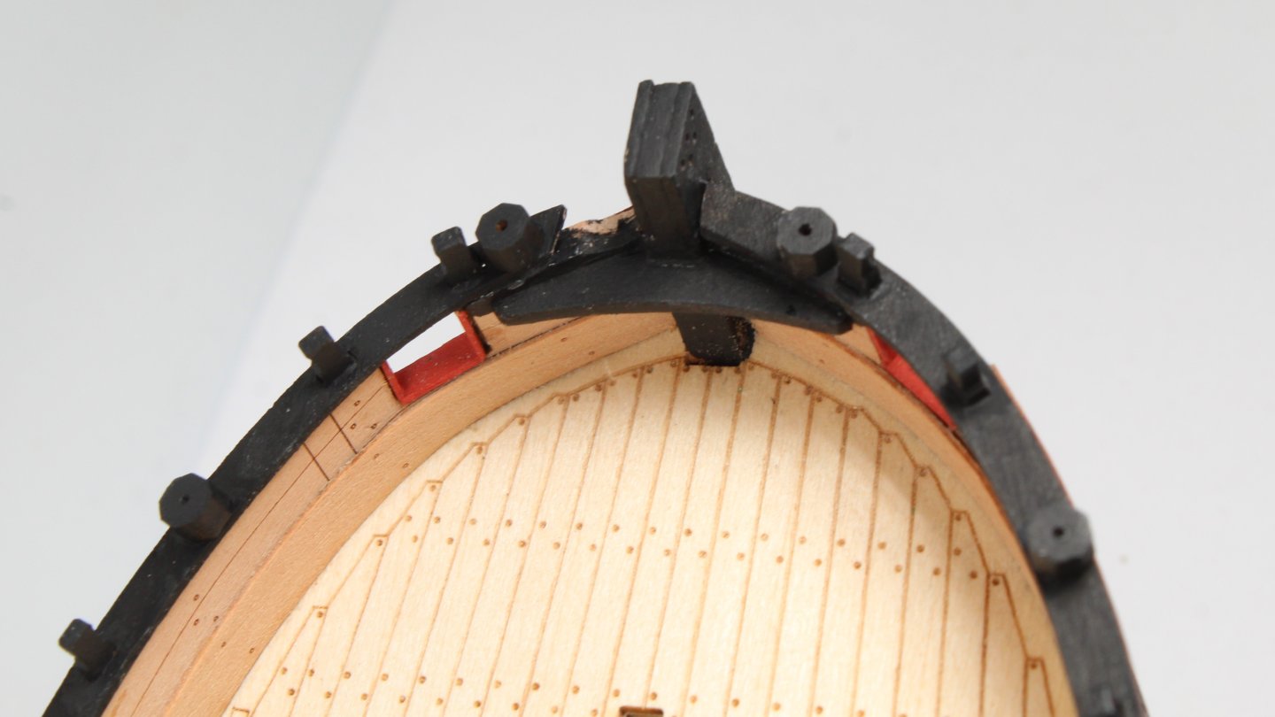
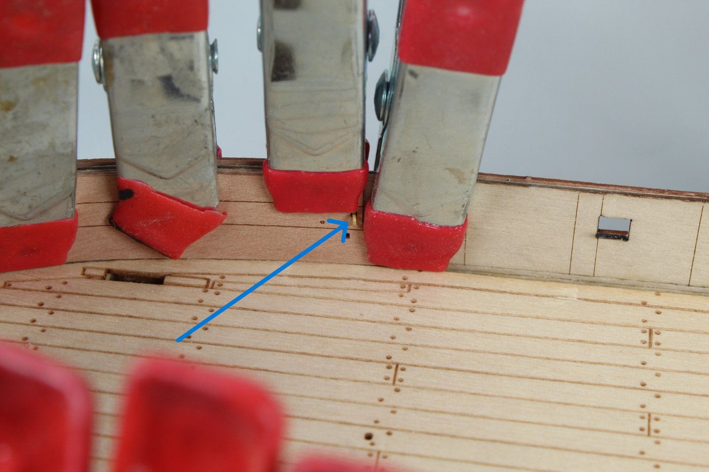
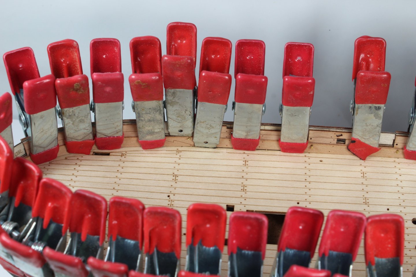
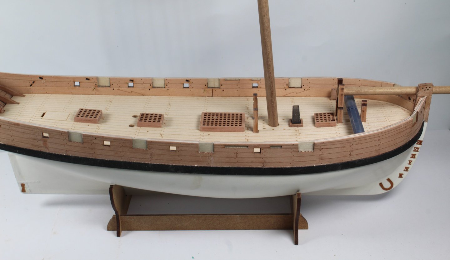
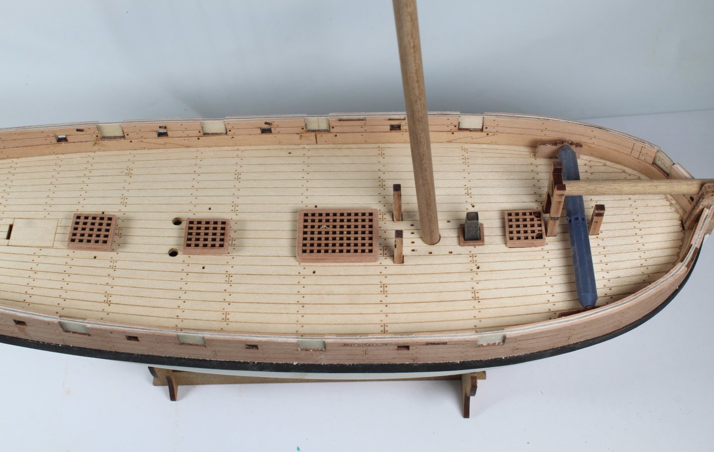
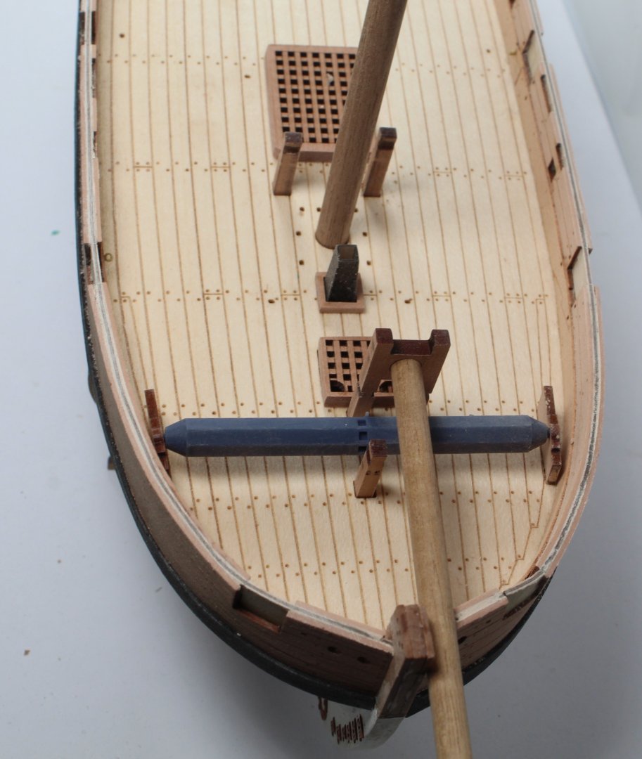
Today's task was to glue the two laser etched patterns to the forward and rear deck bases. This was a task that I took my time, with plenty of dry fitting of items that would be added later on in the build process. I started with the rear deck section. After checking the rear cabin pattern would locate in the slot I brushed plenty of plenty of wood glue on the base and I carefully aligned the laser etched deck pattern and used plenty of clamps. I also made sure once the deck pattern was in place that the rear cabin pattern would still locate in the slot. All was good, as can be seen in the photo below. Once the clue had cured the clamps were removed and the assembly was added to the hull framework. The deck is held in place with 4 locking keys, as indicated by the blue arrows in the following photo. I was very pleased that everything was a perfect fit and the locking keys were inserted without any issues. The rear panel was test fitted once again, and all looks good. Before adding the laser etched deck to the front deck base I wanted to make sure that the various key components would locate in their respective slots. This is shown in the next two photos. All looks good. It was now a case of brushing plenty of glue to the base and then clamping the laser etched deck in place. I used the sail room framework assembly to ensure the laser etched deck was correctly aligned. As the glue was curing I made a few more checks that the various deck items would locate fully in their respective slots. By taking my time with the aspect of the build I am very happy that the various deck items could be fitted without any issues. It was then a case of adding the forward deck assembly to the hull frame work. Once again the locking keys were inserted without any issues. The two cable house sides were also added to the hull frame and were locked in to place using a series of locking keys. The deck items and cabin patterns were test fitted (again). I have also checked the fitting of one of the deck beams and I was pleased that it was a perfect fit. So far so good and I think taking time to double check the fittings before gluing parts together has certainly paid dividends. There are a few more parts to add before diluted glue will be painted in to the various bulkhead and deck joints.


- 241 replies
-
- 13
-
-
- Vanguarrd Models
- Harpy
- (and 1 more)
-
Your planking is very impressive. What sanding sealer are you planning to use?
-
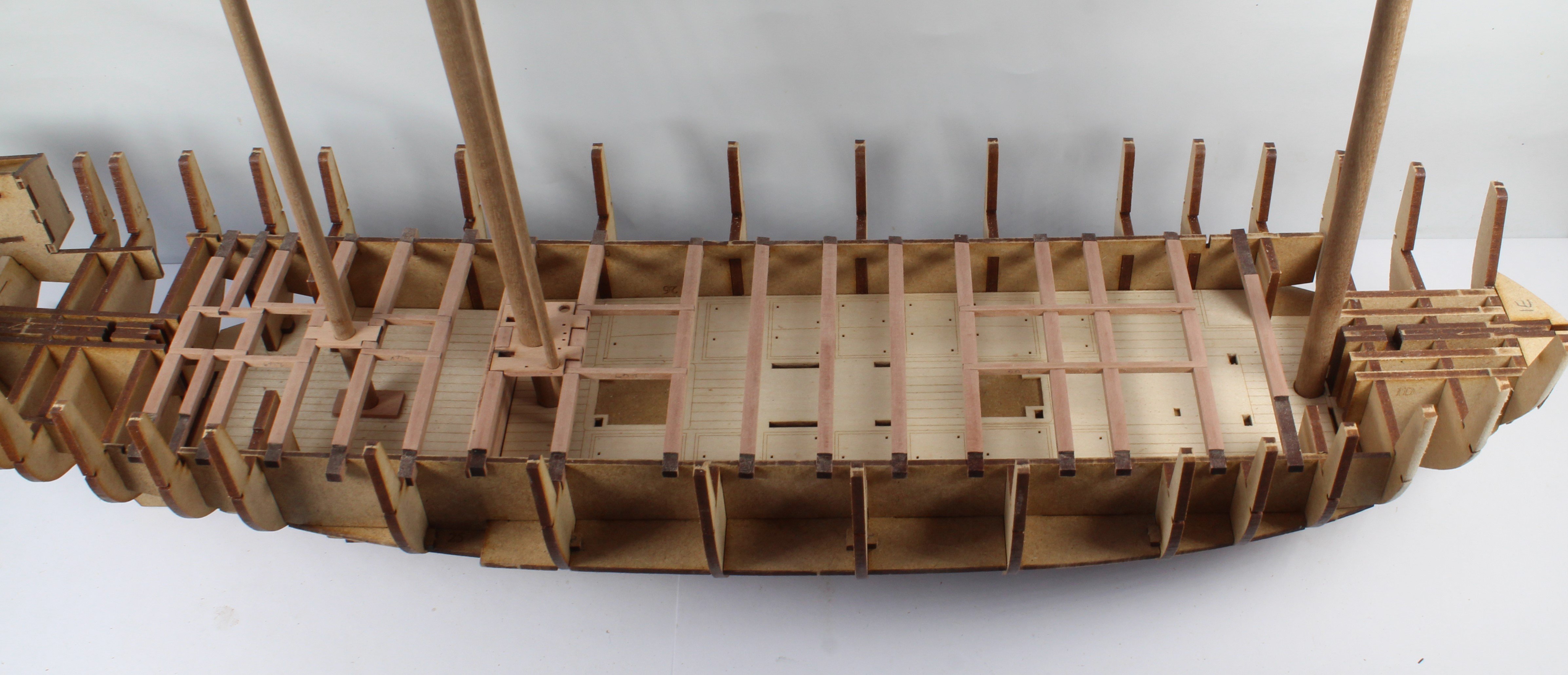
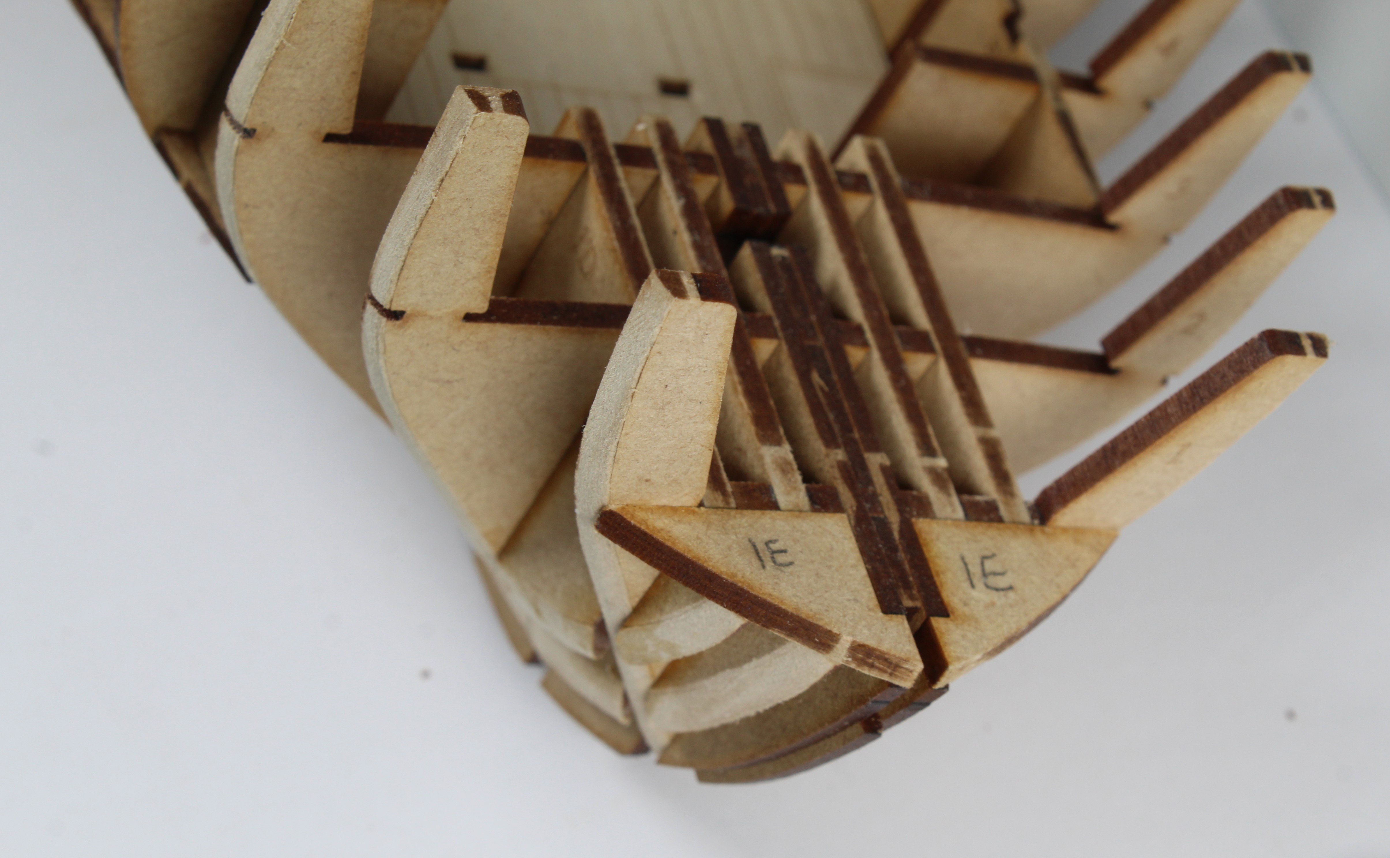
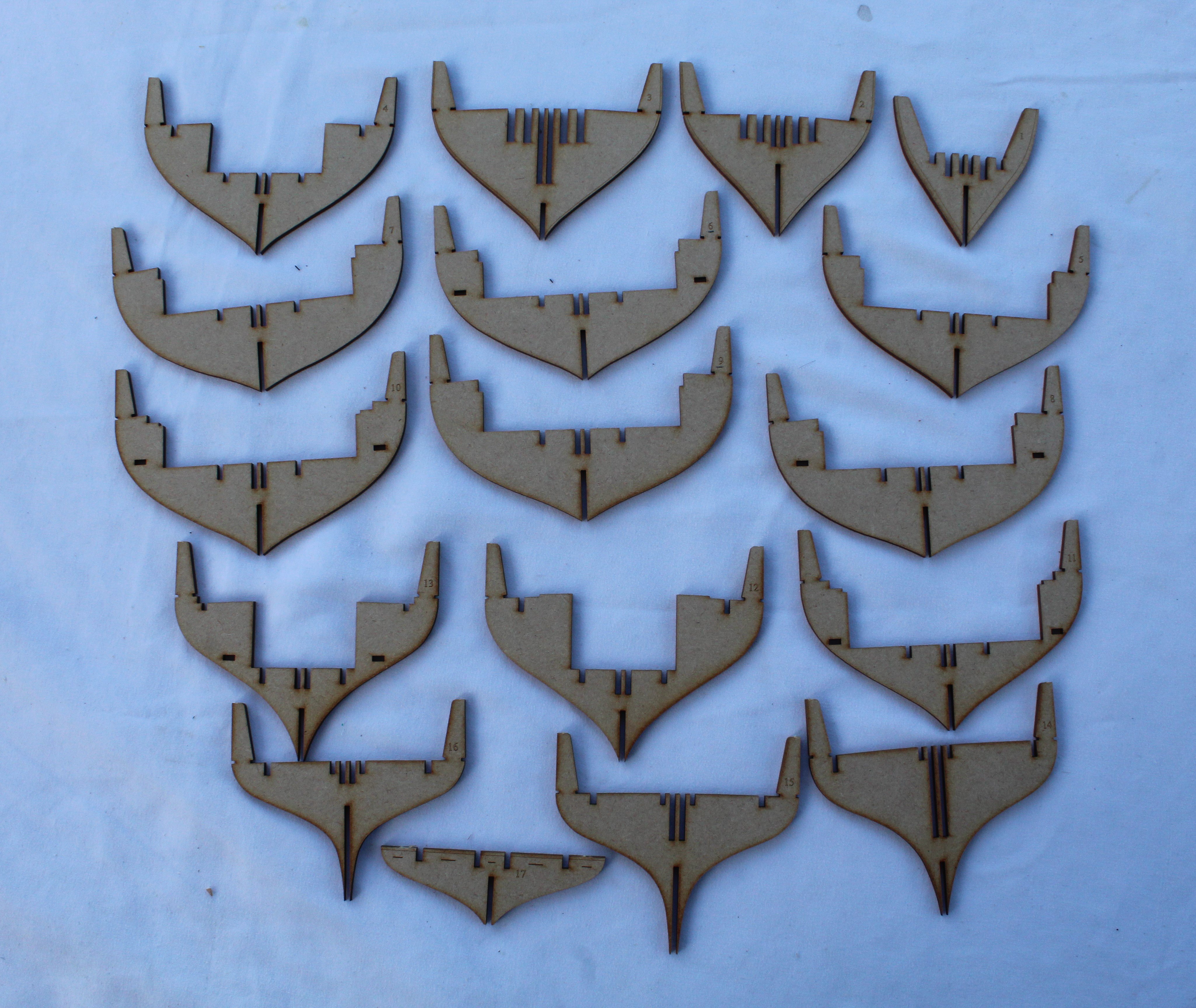
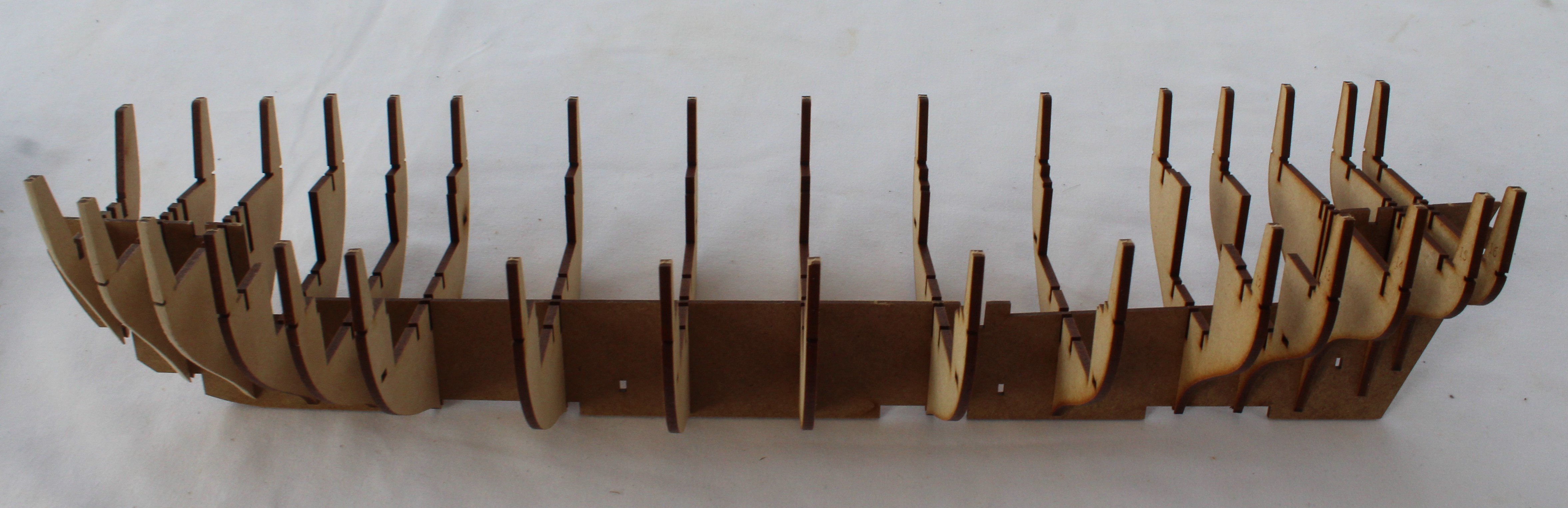
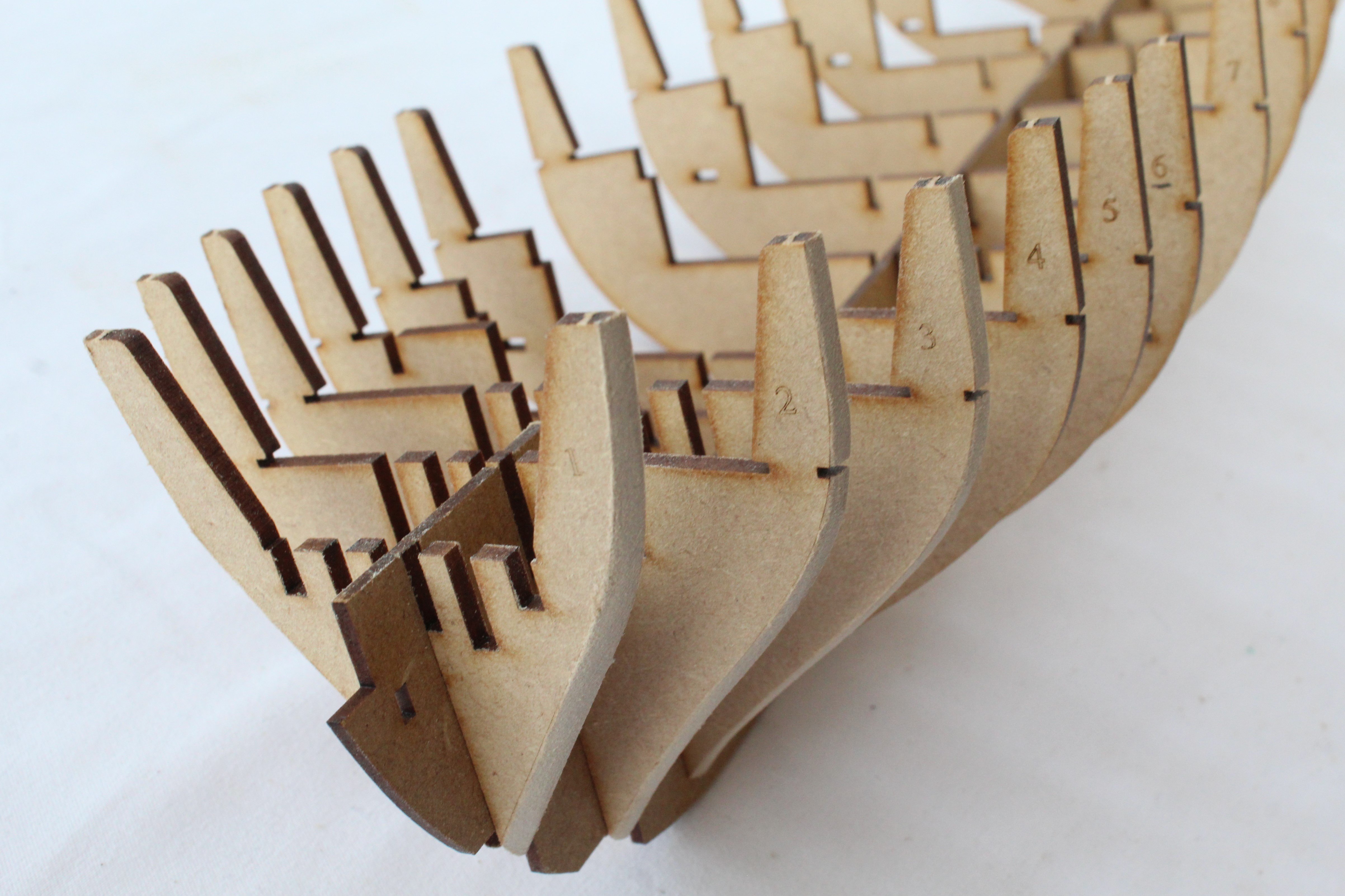
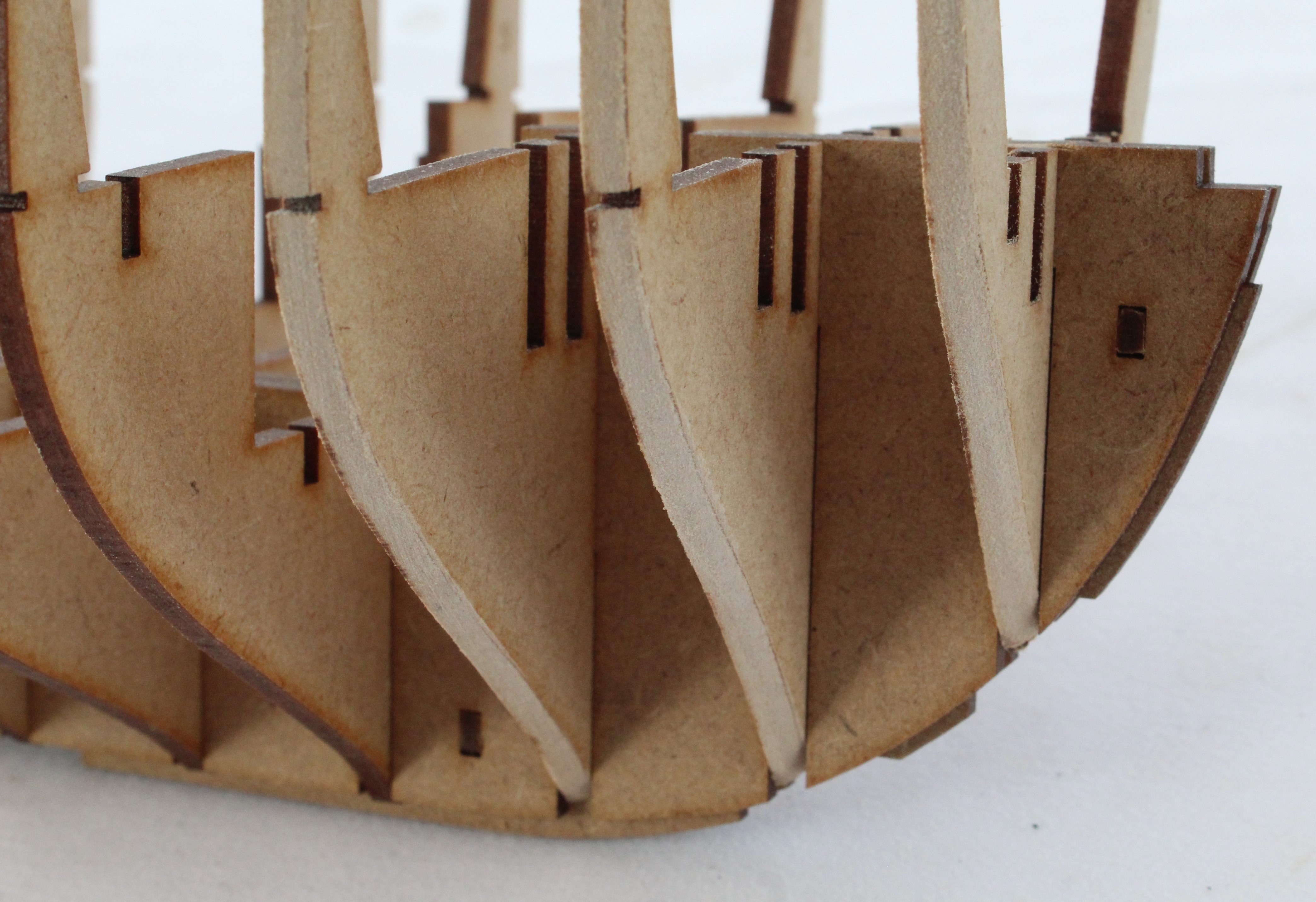
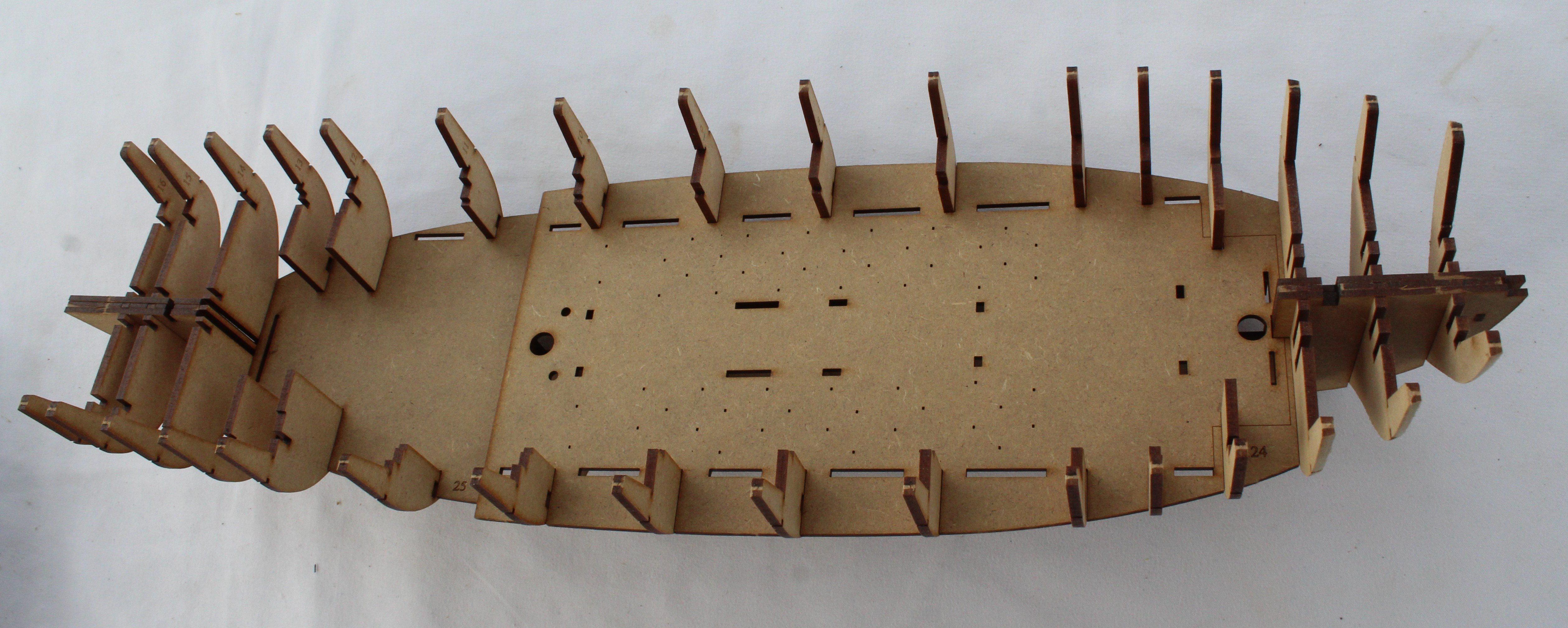
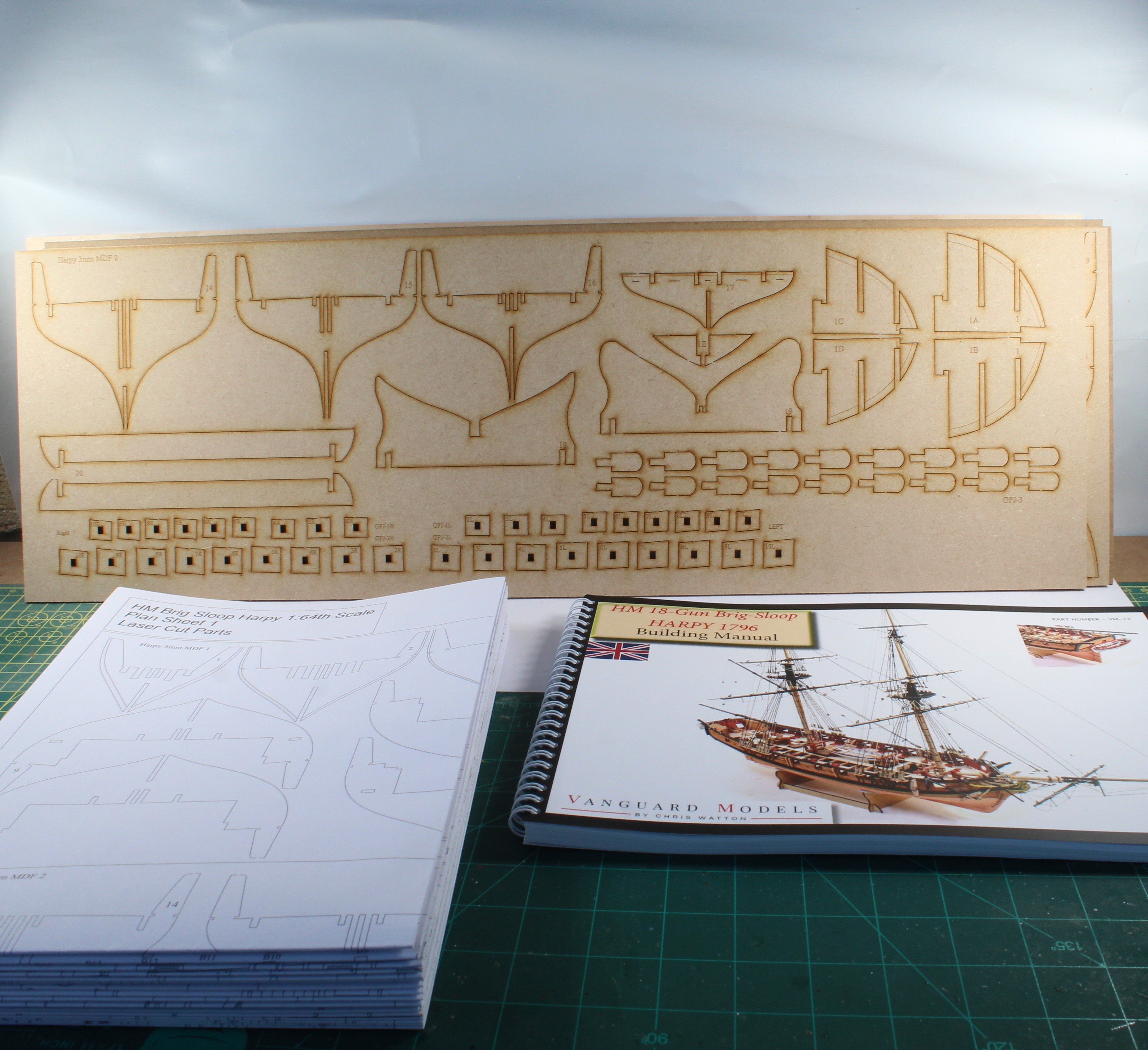
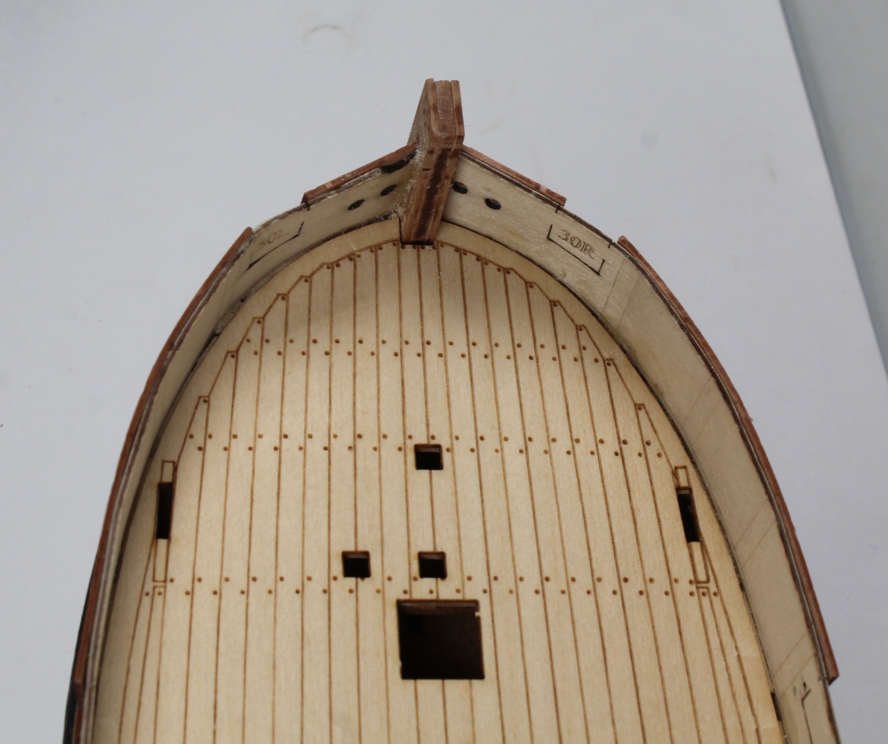
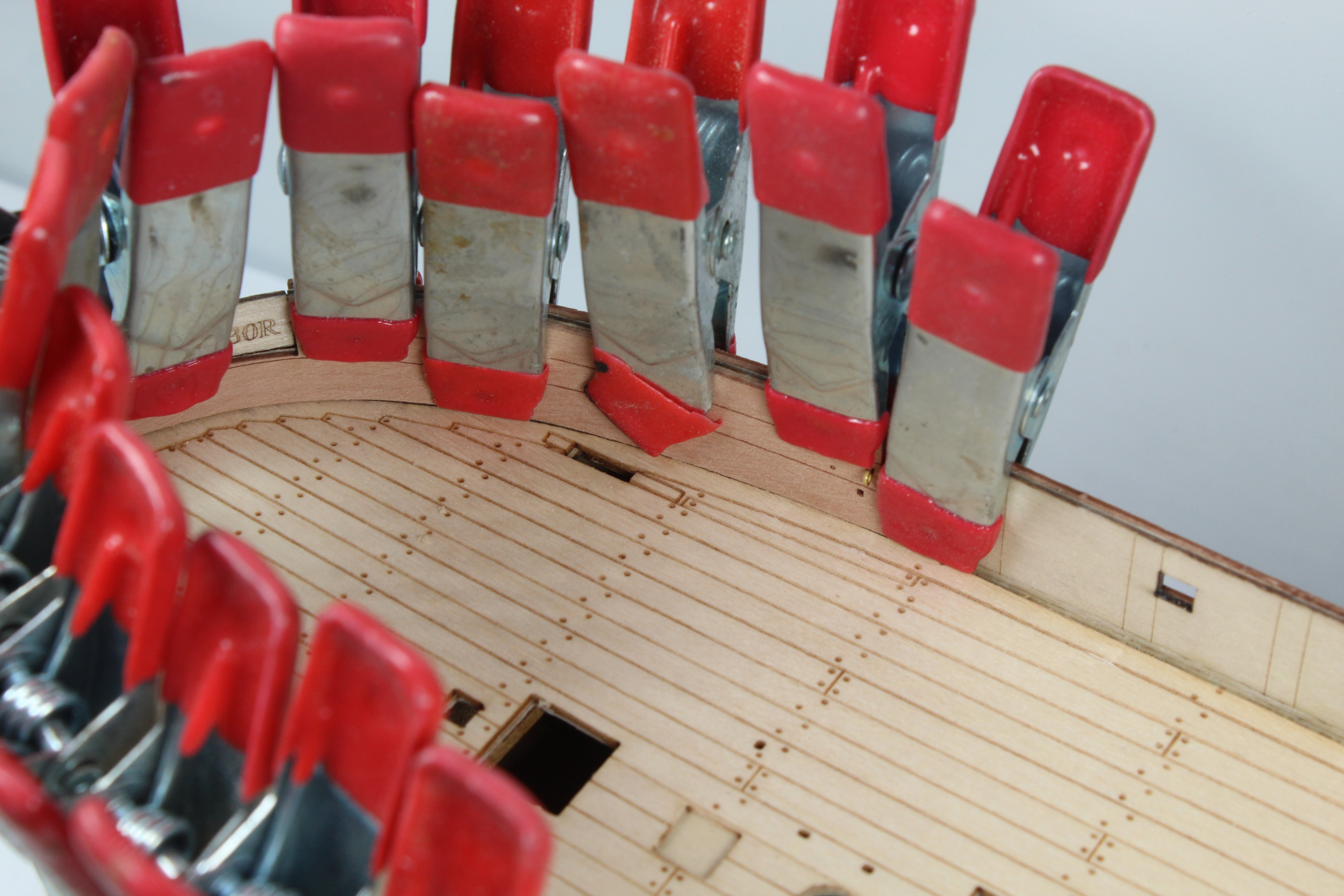
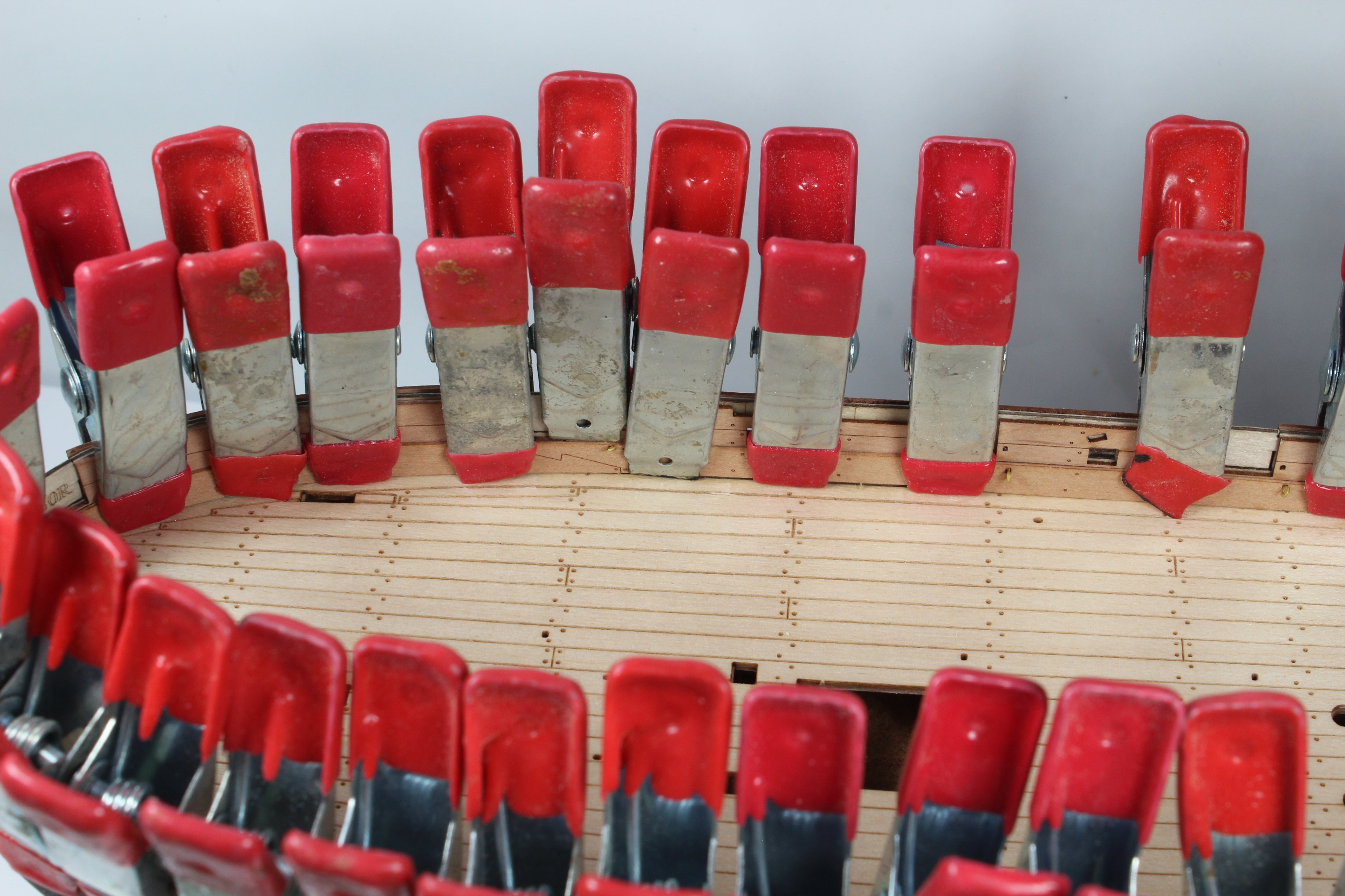
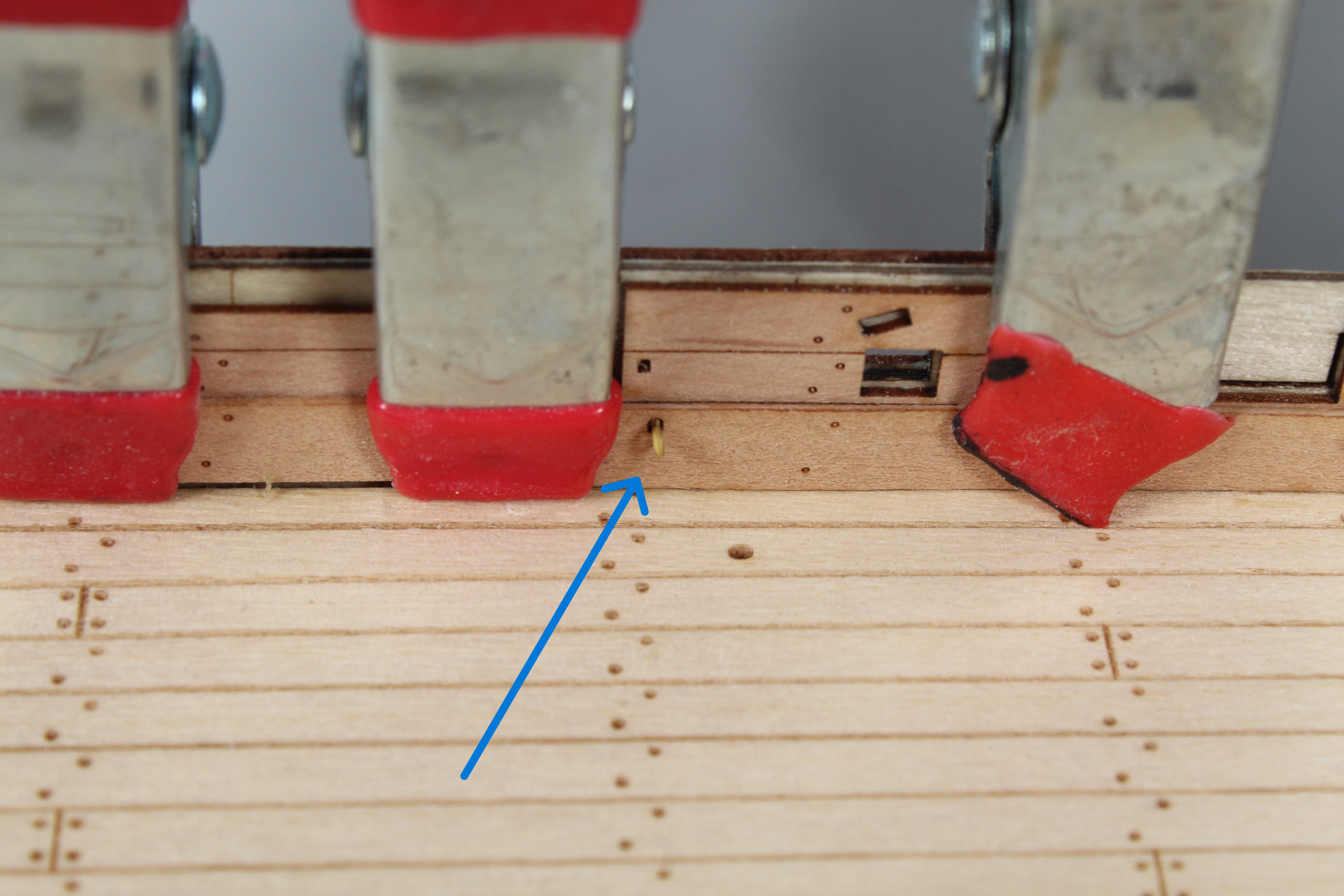
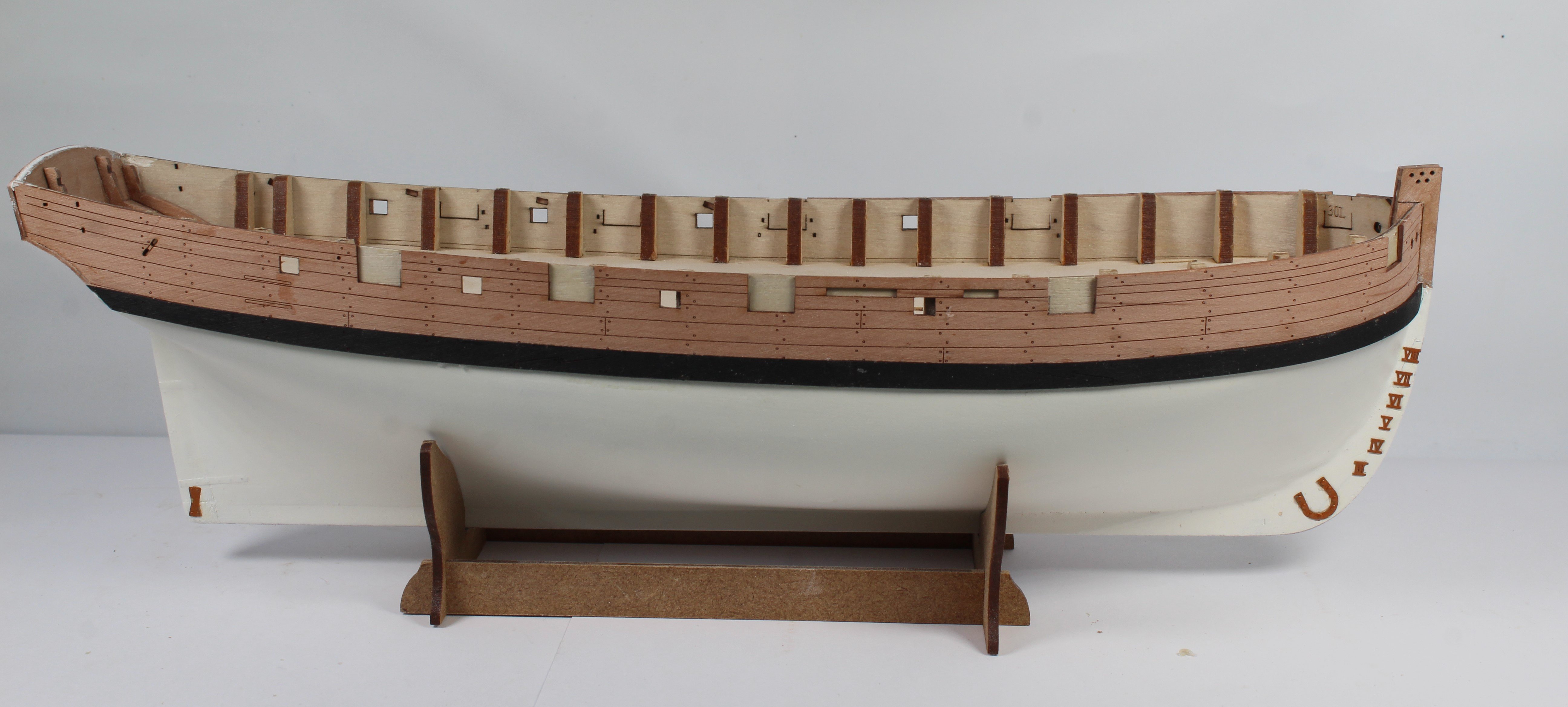
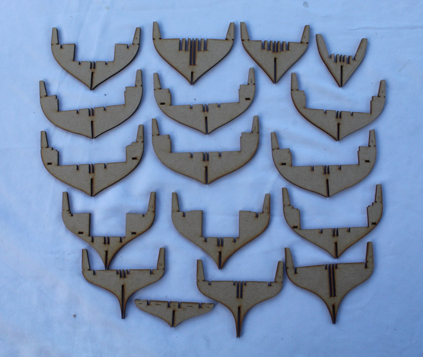
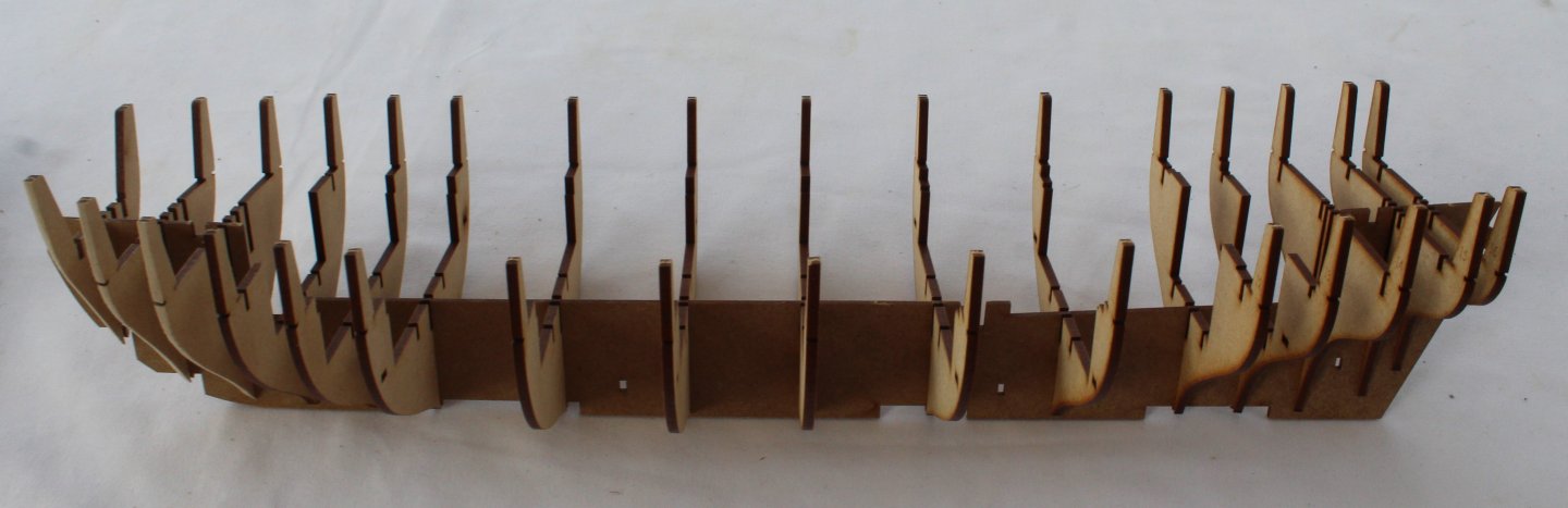
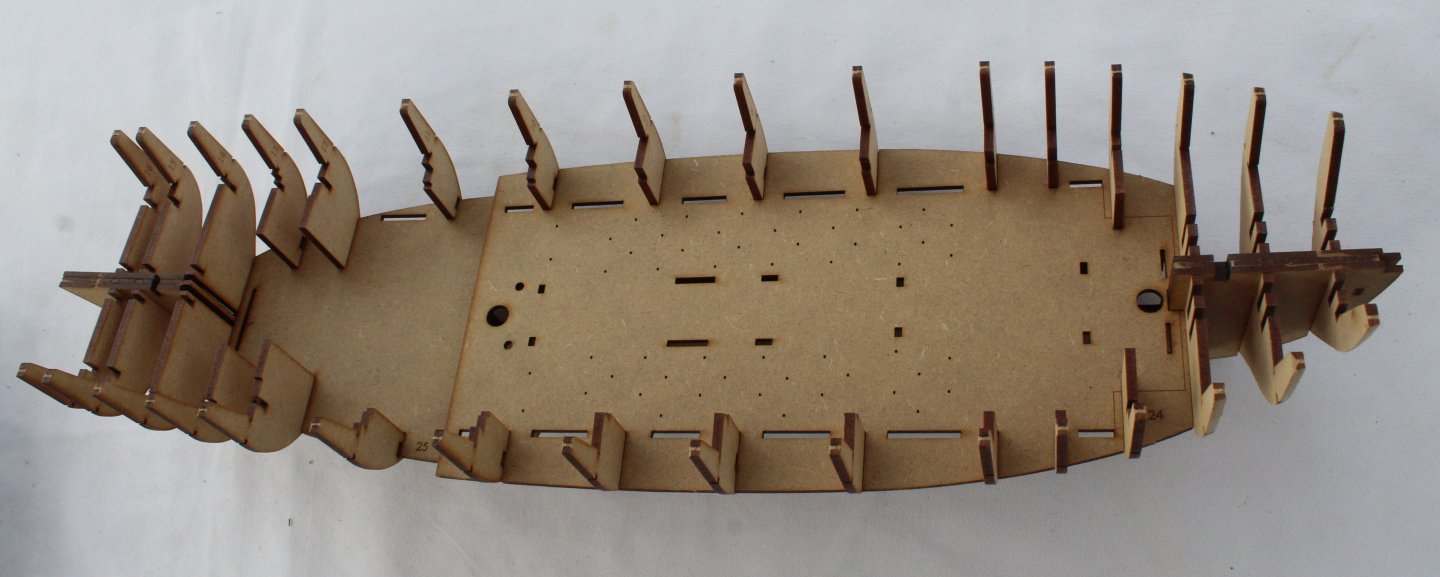
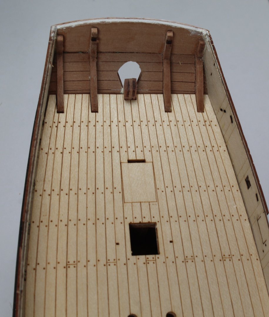
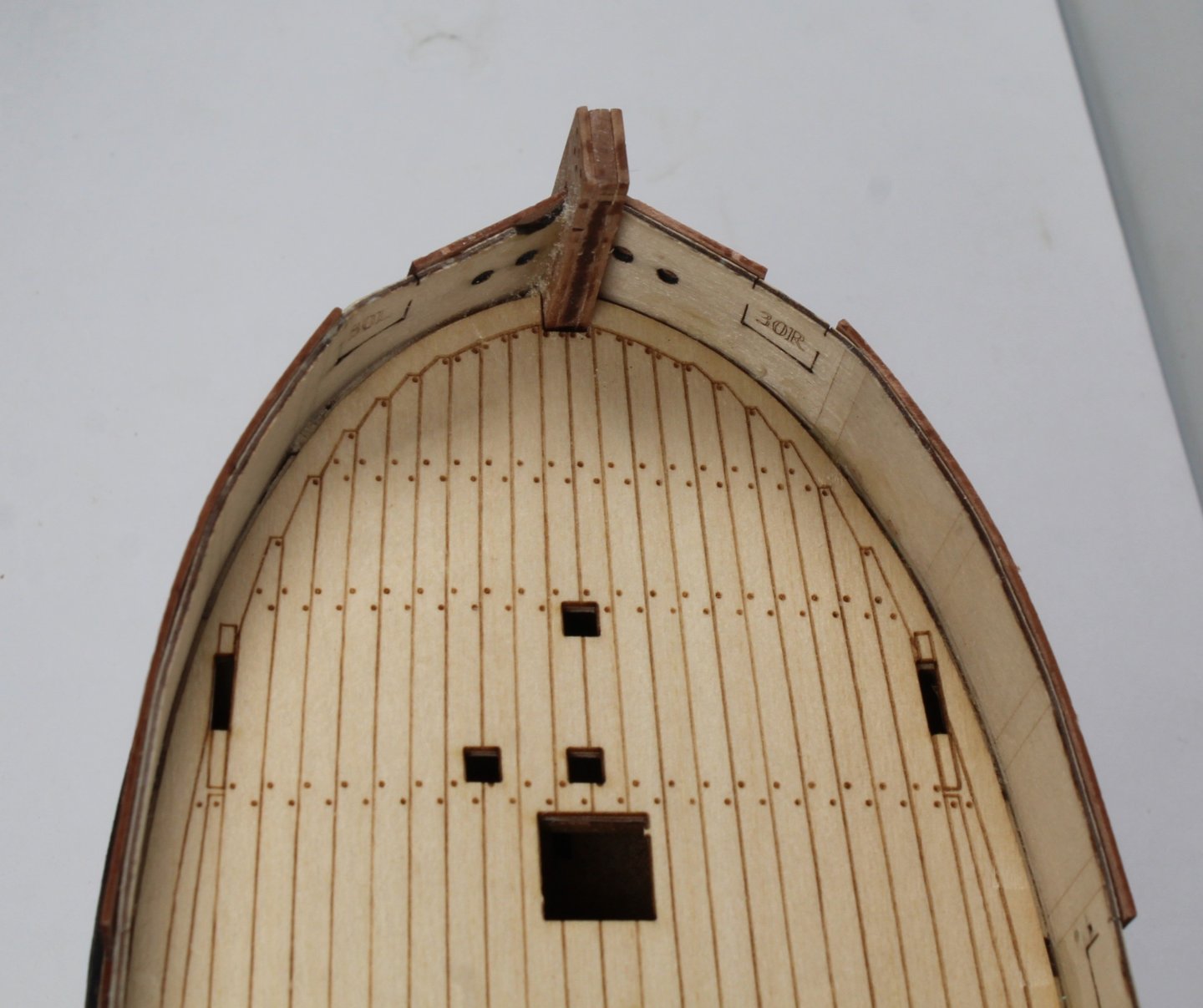
It is now time to start the Harpy build in earnest. The first task was to remove the bulkheads from the MDF sheets. There are 17 bulkheads in total. There are laser engraved guide lines on bulkheads 1, 2 & 3 which enable these parts to have the initial pre fairing bevelling. I really like this design aspect. I used a combination of a Ginour rotary tool and sanding stick to bevel these bulkheads to the guide lines. Bulkheads 1 -16 were then inserted into their respective positions on the keel, ensuring they were all fully engaged. As per normal with the Vanguard Model builds no glue is used as this stage. The keel is very flimsy so thankfully this is soon corrected when the two keel doublers are added. To ensure these keel doublers are correctly aligned they are held in place using a series of locking keys. The basic hull frames is then strengthen further when the two longitudinal support parts were pushed into place. It was then time to check the installation of the two lower deck bases. No problems were encountered. There are locking keys to hold these deck bases in place, once fitted. However, before that can be done the laser engraved deck patterns need to be glued to the deck bases. When removing the removing the bulkheads I also removed all the other parts from the MDF sheets which were a) the various gun port jigs b) the sail room framework c) Two stern cabin frameworks. When test fitting the forward laser engraved deck pattern there seemed to be a slight alignment issue when using pins located in the eyebolt openings. When I positioned the laser engraved deck using the sail room frame, I was much happier with the overall alignment, but I may need to use a micro drill for some of the eyebolts. In the photo below the laser etched deck is only dry fitted as I was checking which rubber bands would be best to hold the deck in place while the glue cures. I also want to check the other items will fit in the various positions before I commit to gluing the parts in place. When looking at the laser engraved scuttles, I did consider copying Blue Ensign approach to plank the deck base and to add scuttle covers but after a little bit of thought I have decided to just use the laser engraved deck pattern as is. I will plan to follow Blue Ensign idea to fit a printed brick pattern for the stove base area as I think that it really enhances the build. I have also ordered some different hinges and handles from Syren which I will use for all the internal panel doors, as I really liked the ones Blue Ensign has fitted.


- 241 replies
-
- 13
-
-
- Vanguarrd Models
- Harpy
- (and 1 more)
-
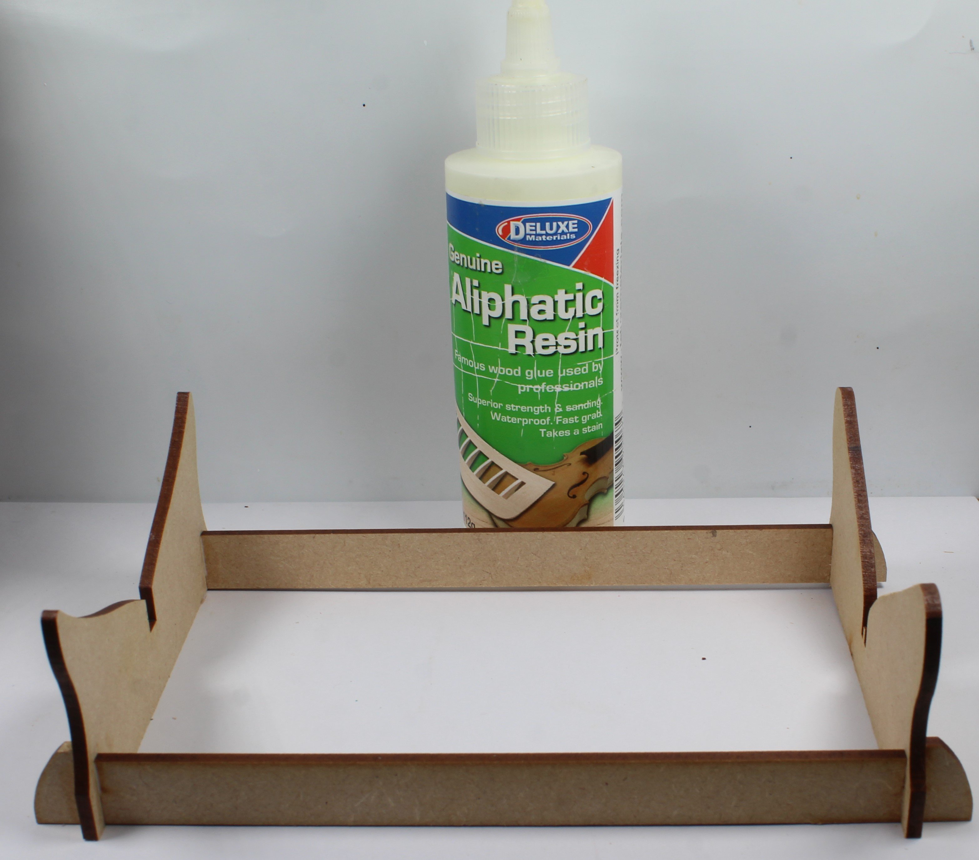
Another new dawn and another new Vanguard Model to build, namely the HMS Harpy. I have been looking forward to starting this build since receiving the kit last month but I decided it was better to complete my work on HM Armed Cutter Sherbourne build. I really like the look of the HMS Harpy and have been very impressed with the design work. I hope that my modelling skills will enable me to do justice to this kit, noting there is still many areas for me to work on to get better results. The shipyard has been cleaned, the tools are ready so it is now time for lights, camera and action. Building The Cradle As with many of the Vanguard Model kits there is an MDF build cradle to assemble. A clear perspex cradle is also provided to display the completed model. Using a sharp craft knife the tabs were cut free from the MDF sheet. I like to score to tabs top and bottom as I find this ensures the parts come out clean and minimal work is then required to remove any unwanted tab nubs with a quick rub using a sanding block. After a quick test fit of the component parts some Aliphatic Resin Wood Glue (Deluxe) was added to the locating slots and the cradle was assembled. Although not really necessary for the cradle, but is good practice, the excess wood glue was wiped clean. After a busy morning in the shipyard it is now time for a well earned cup of Yorkshire tea.


- 241 replies
-
- 13
-
-
- Vanguarrd Models
- Harpy
- (and 1 more)
-
Thanks for the comments and likes. I plan to start work on the Harpy this week and I will start a build log.
- 43 replies
-
- 4
-
-
- Vanguard Models
- Sherbourne
- (and 1 more)
-
Many thanks. Yes I have a couple of cans of compressered air which will keep the boats dust free.
-
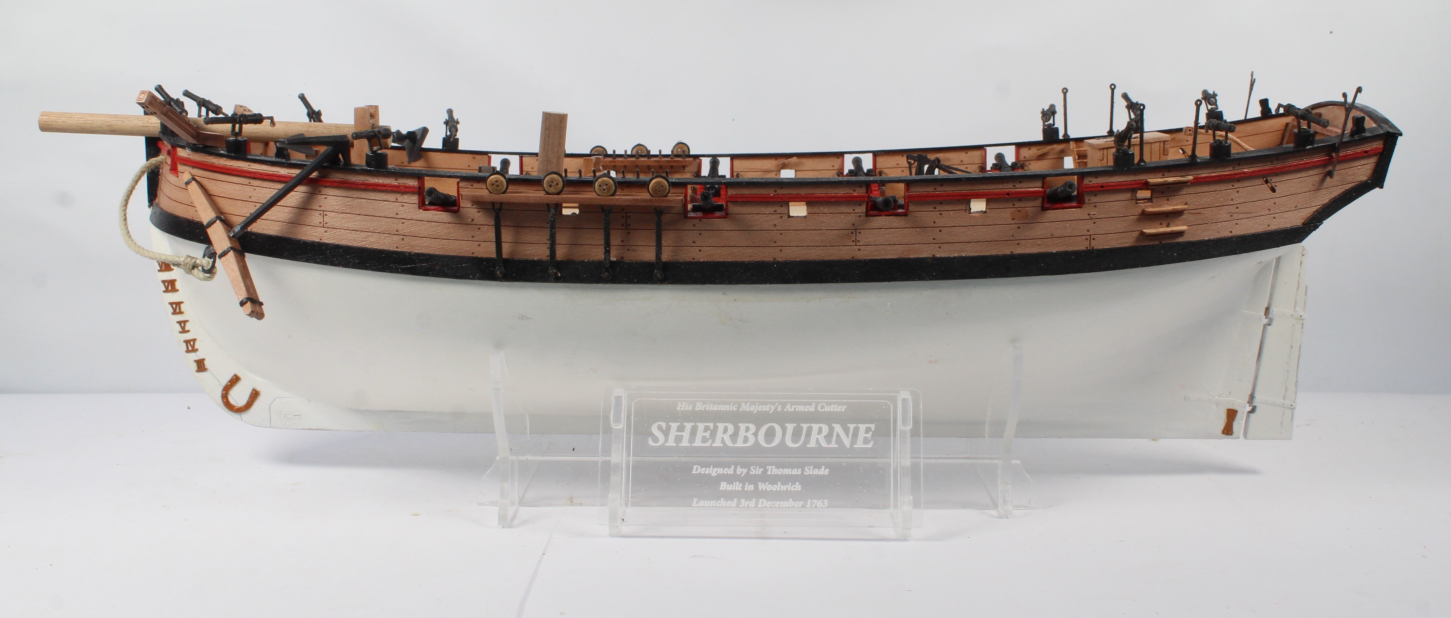
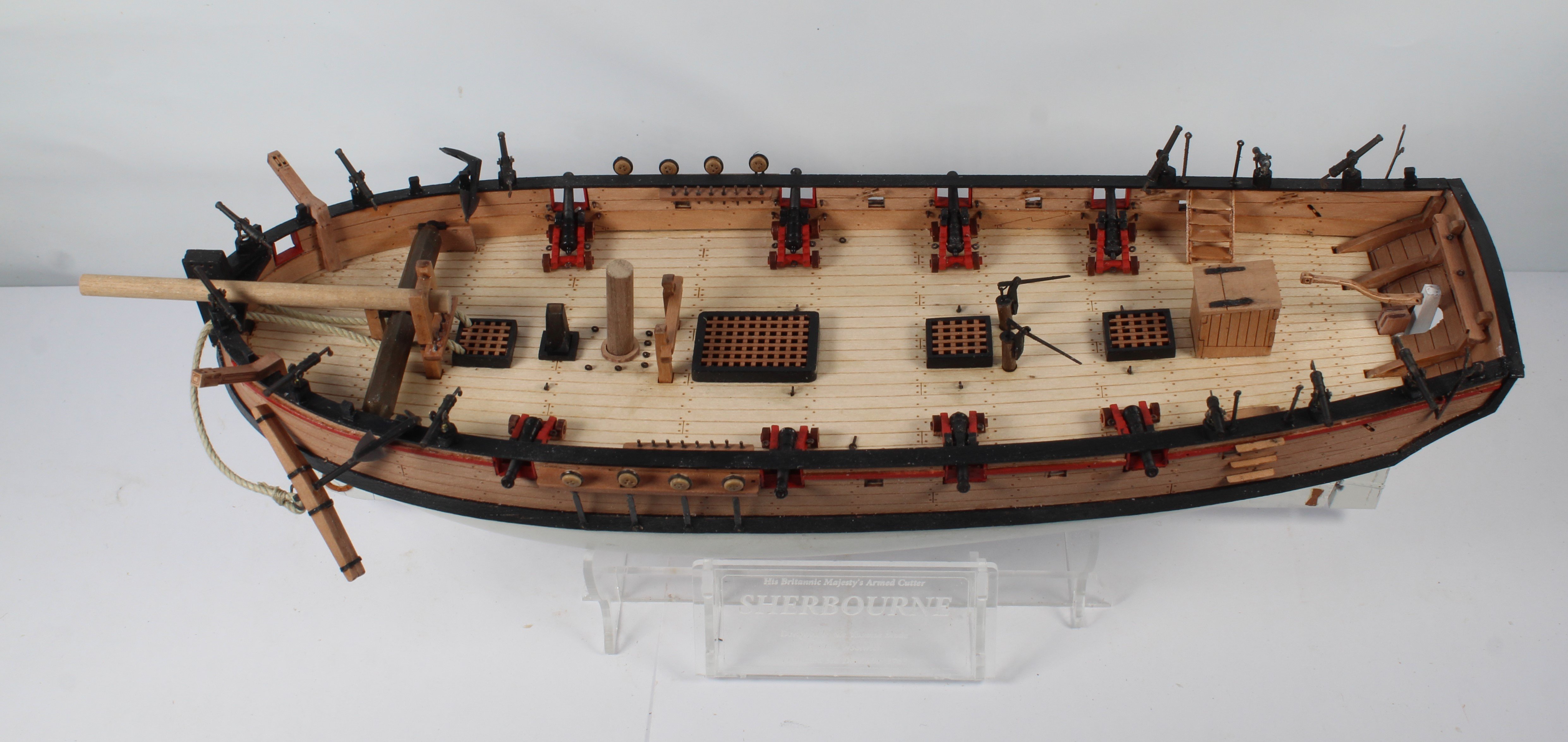
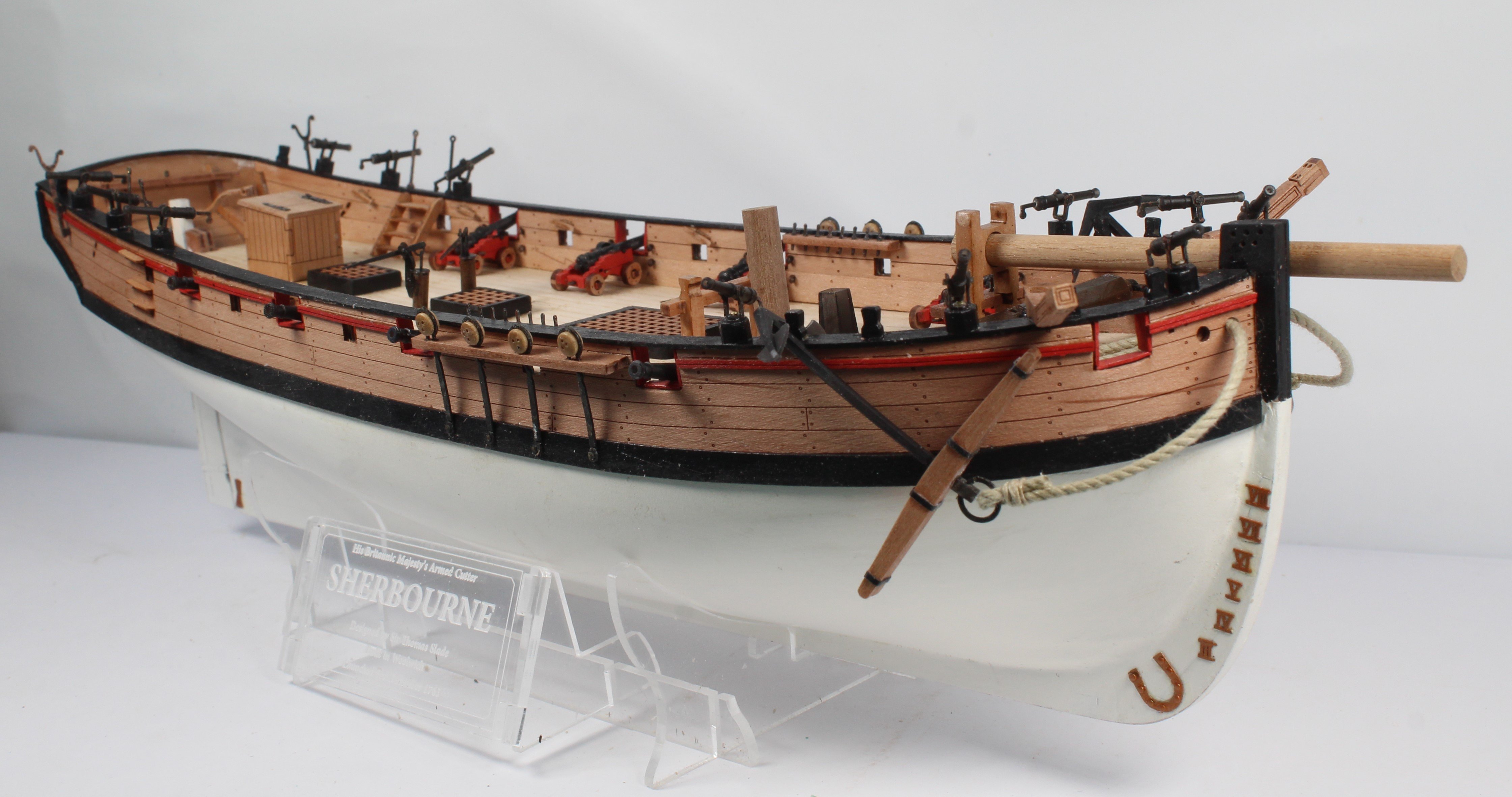
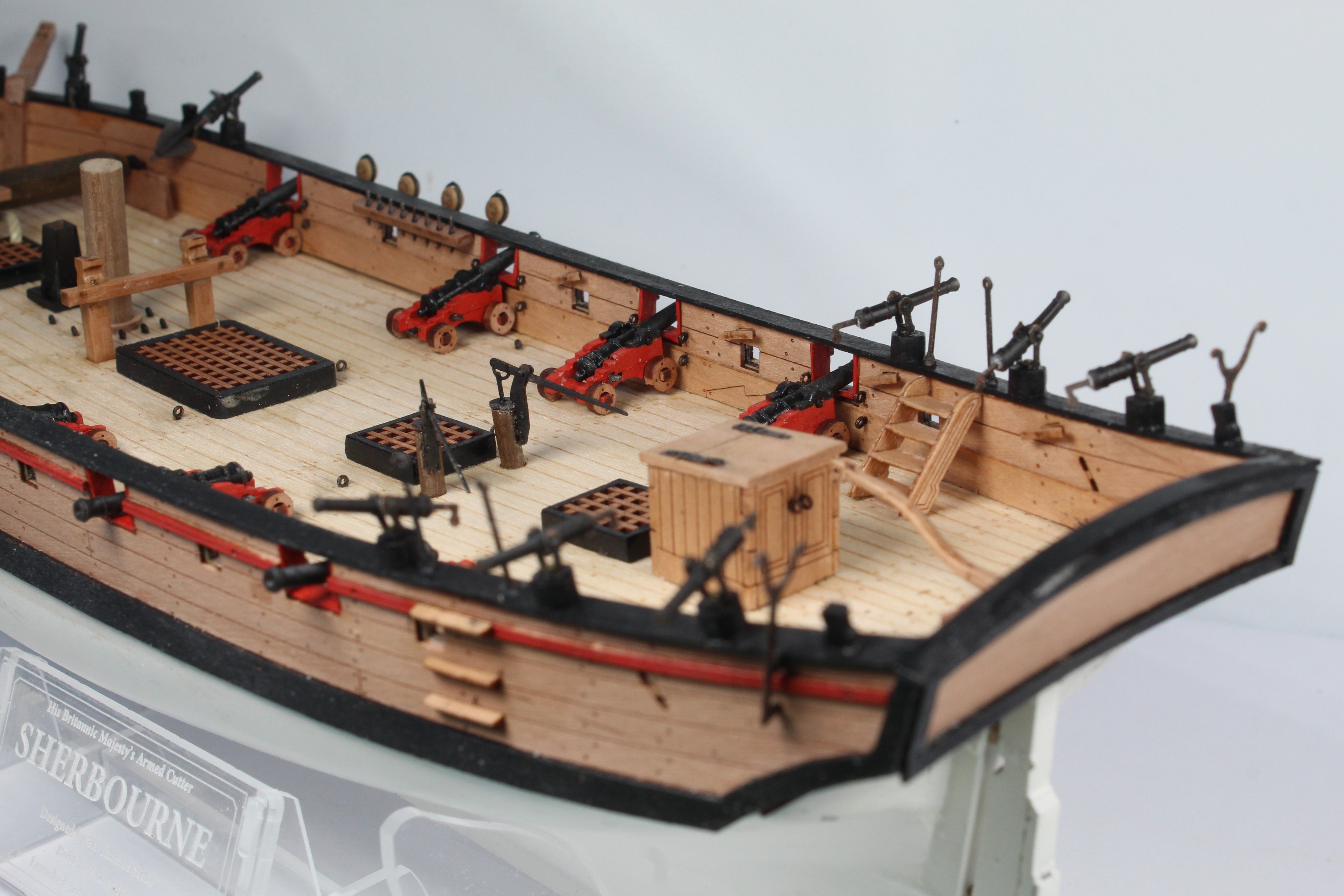
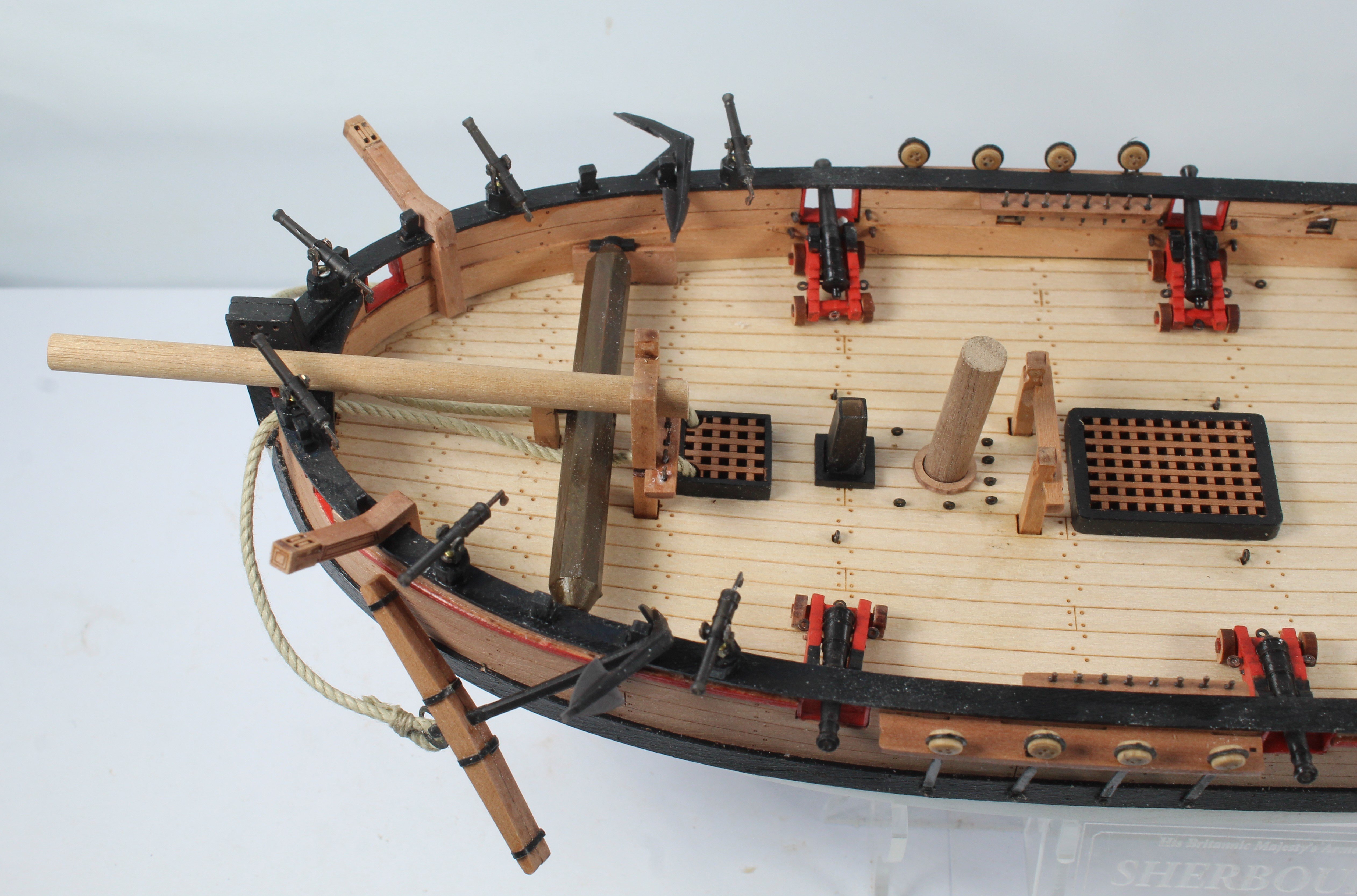
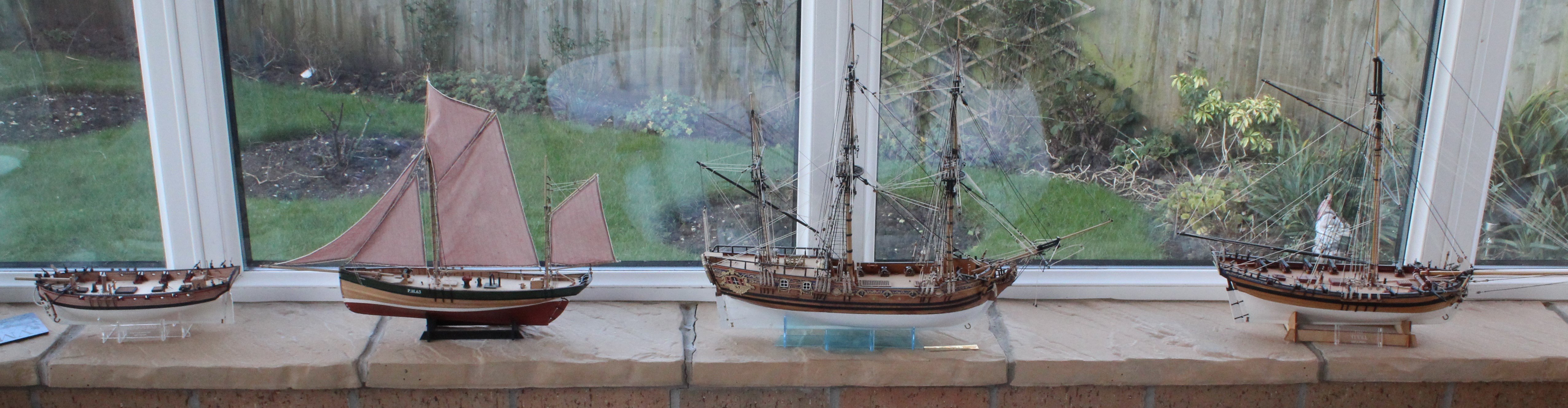
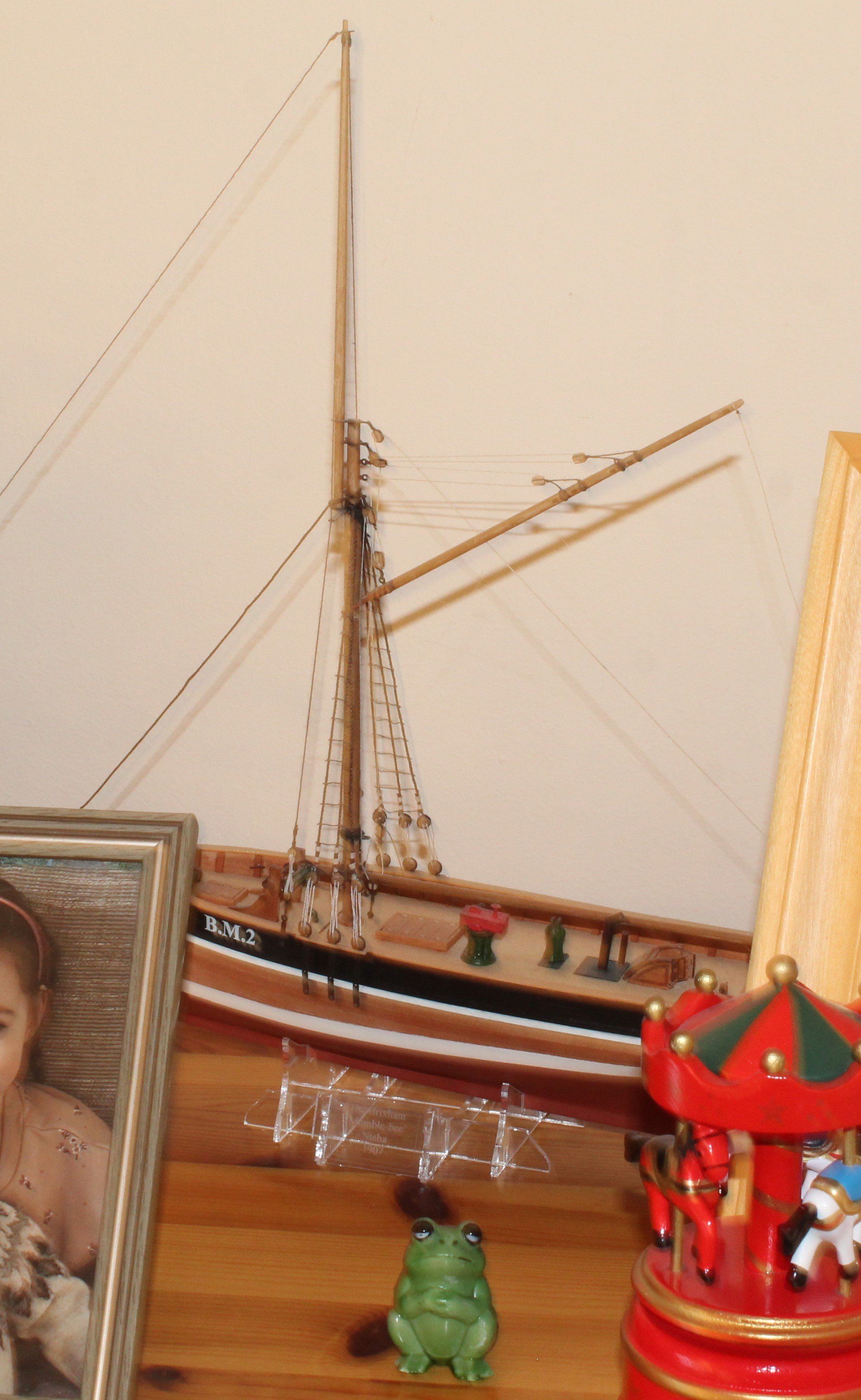
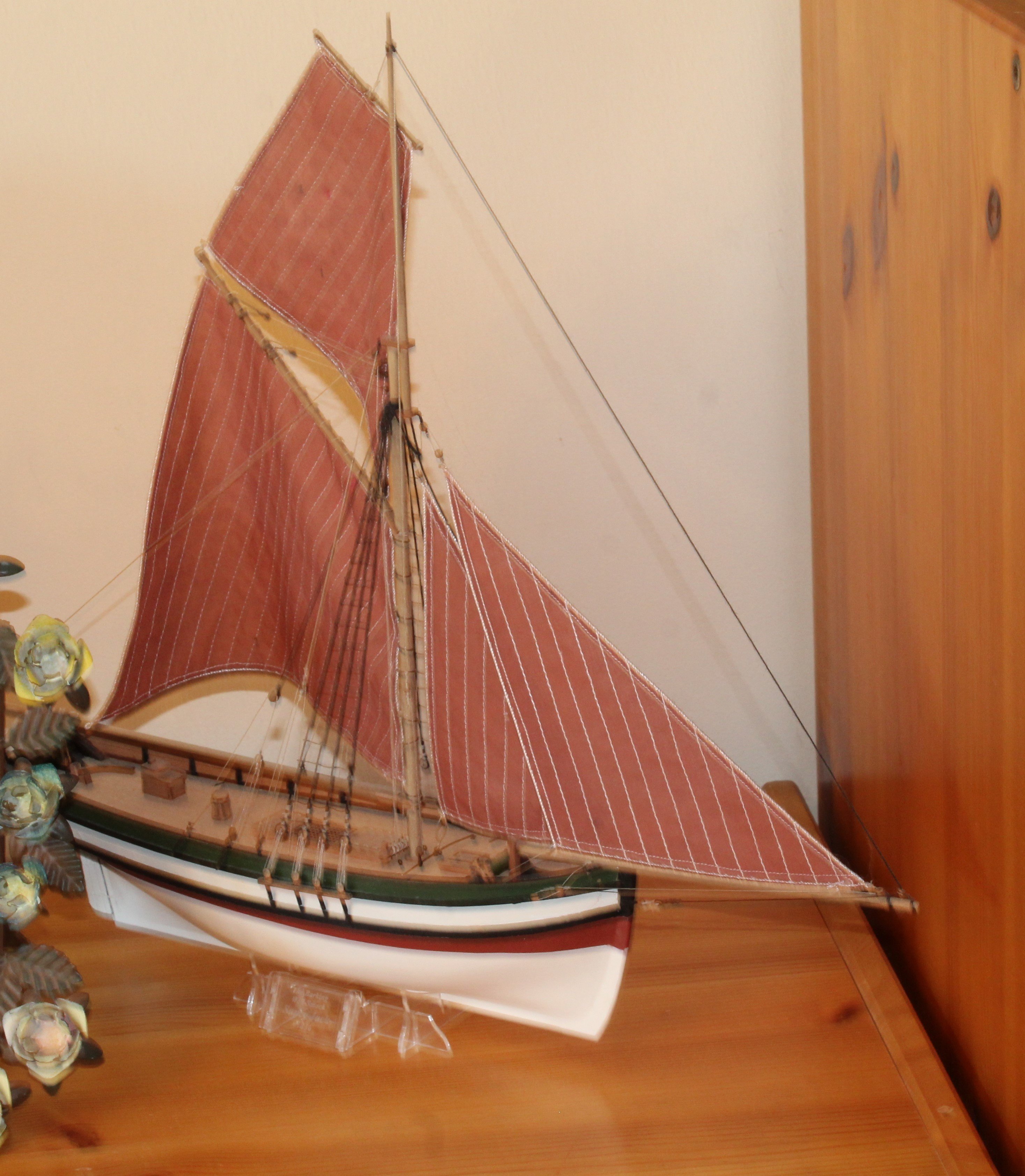
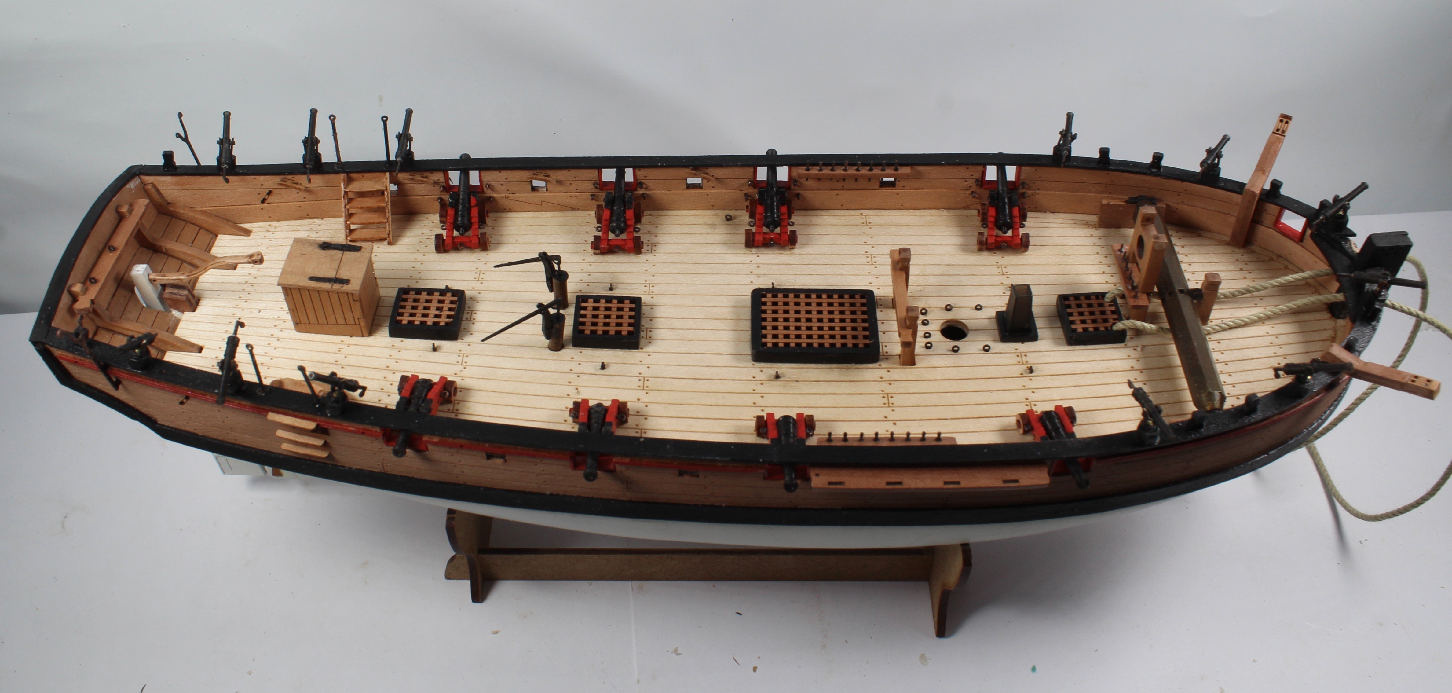
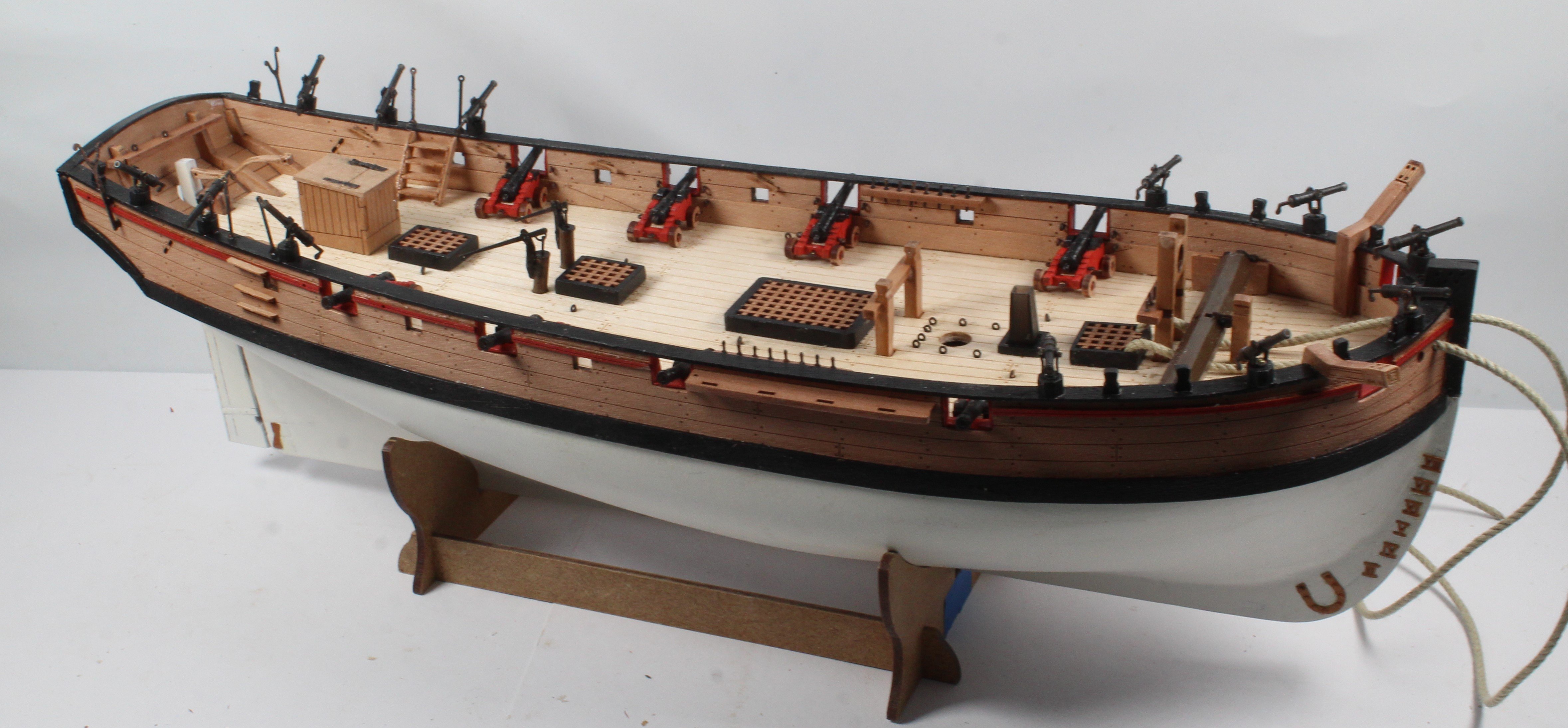
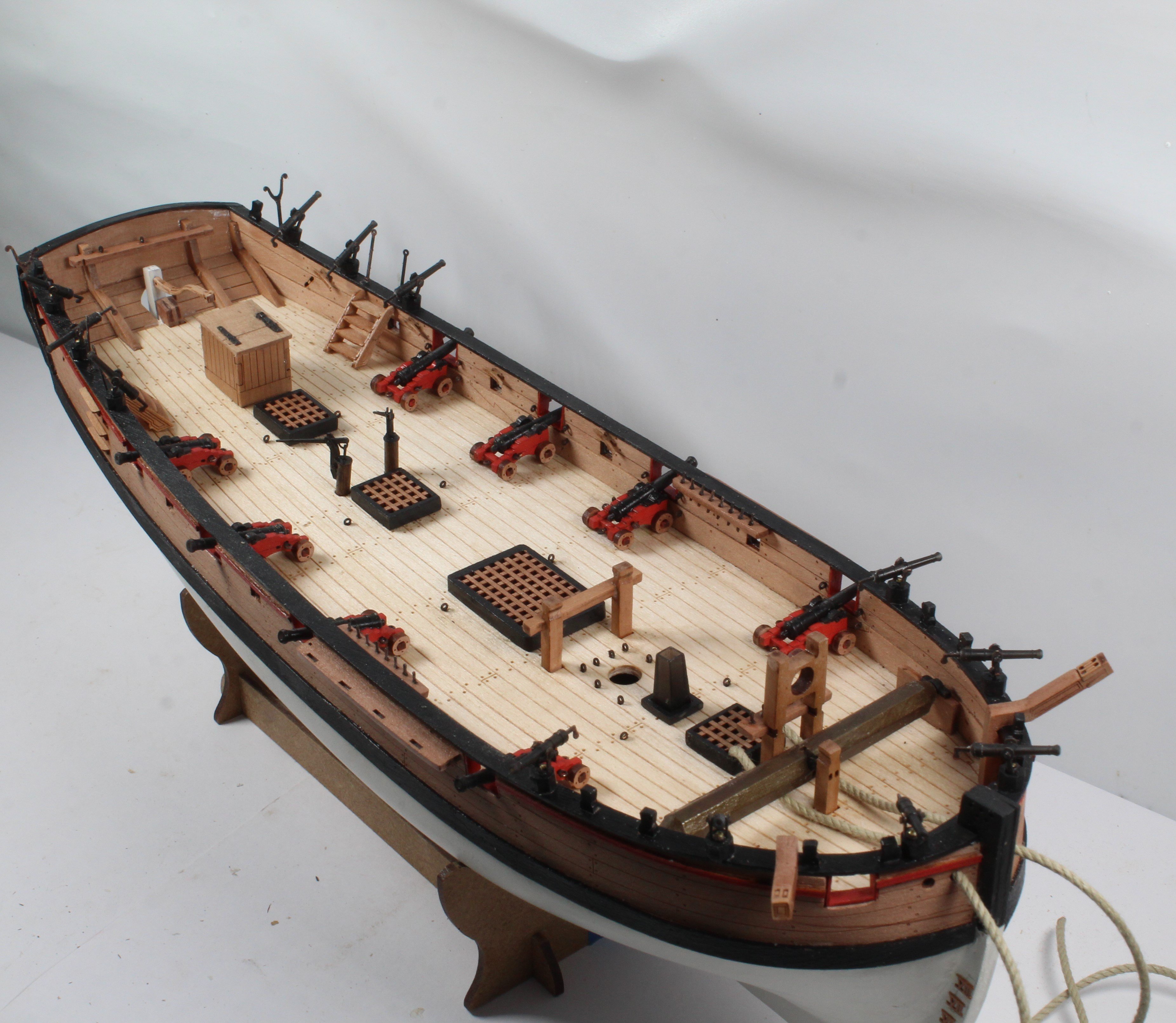
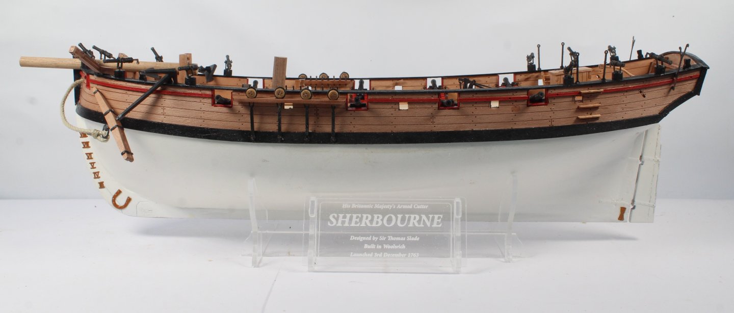
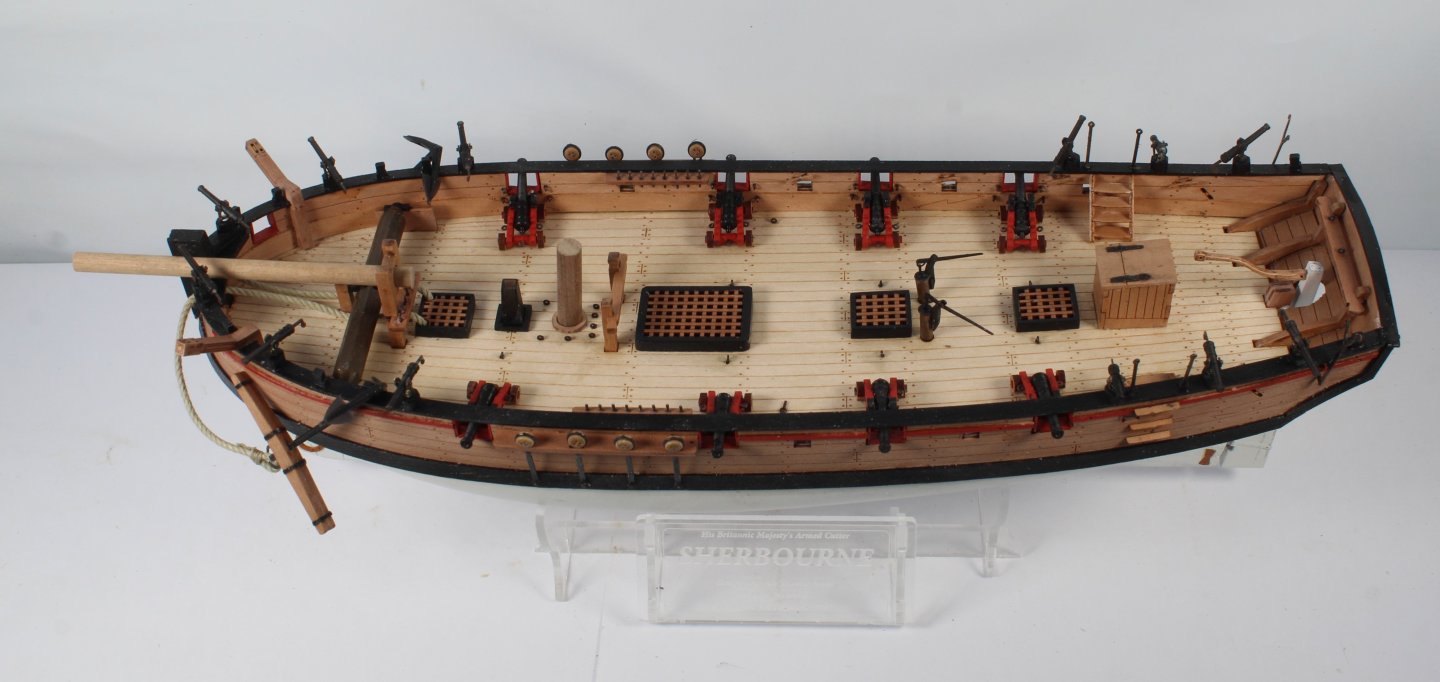
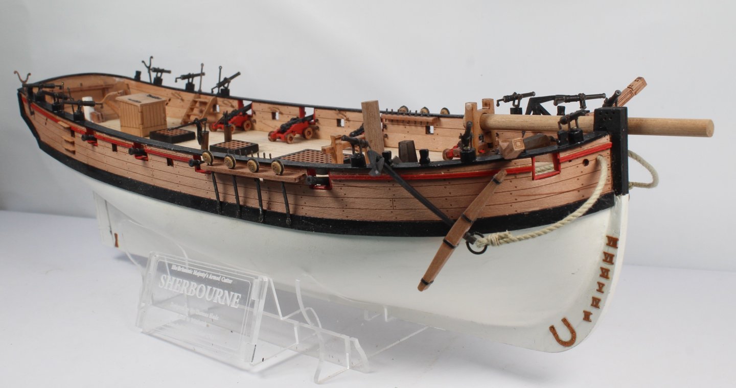
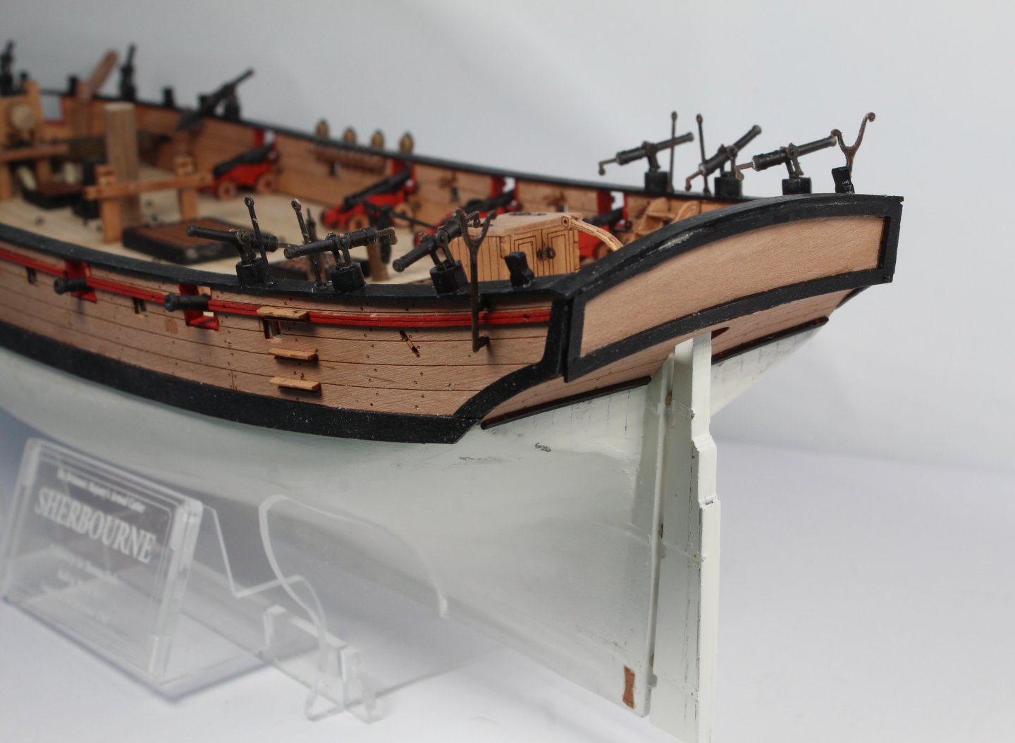
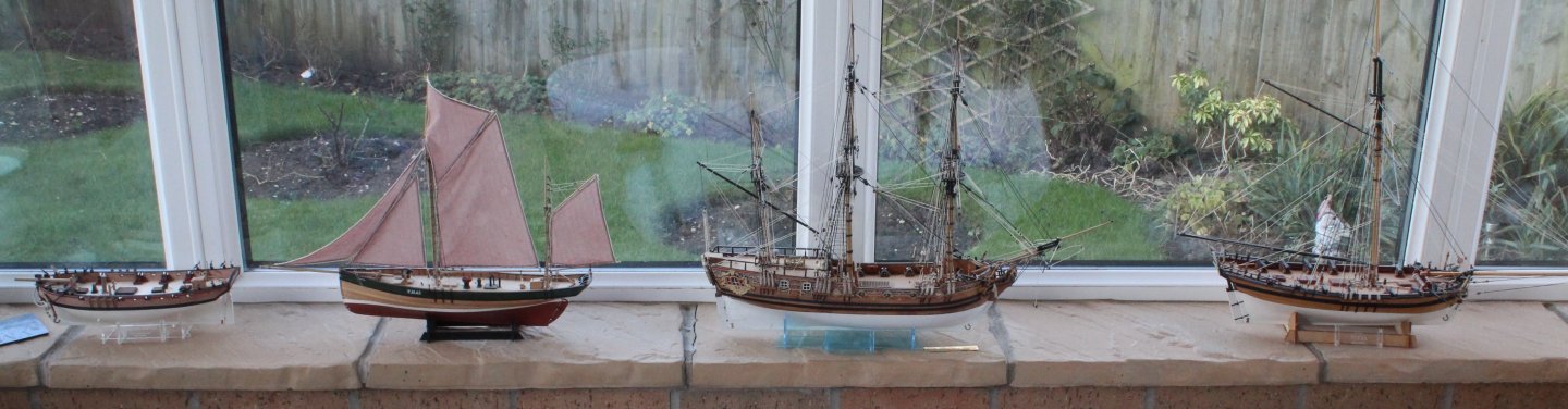
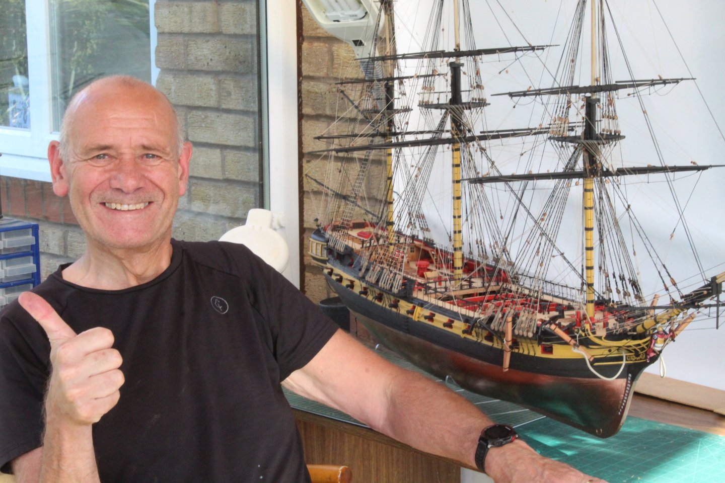
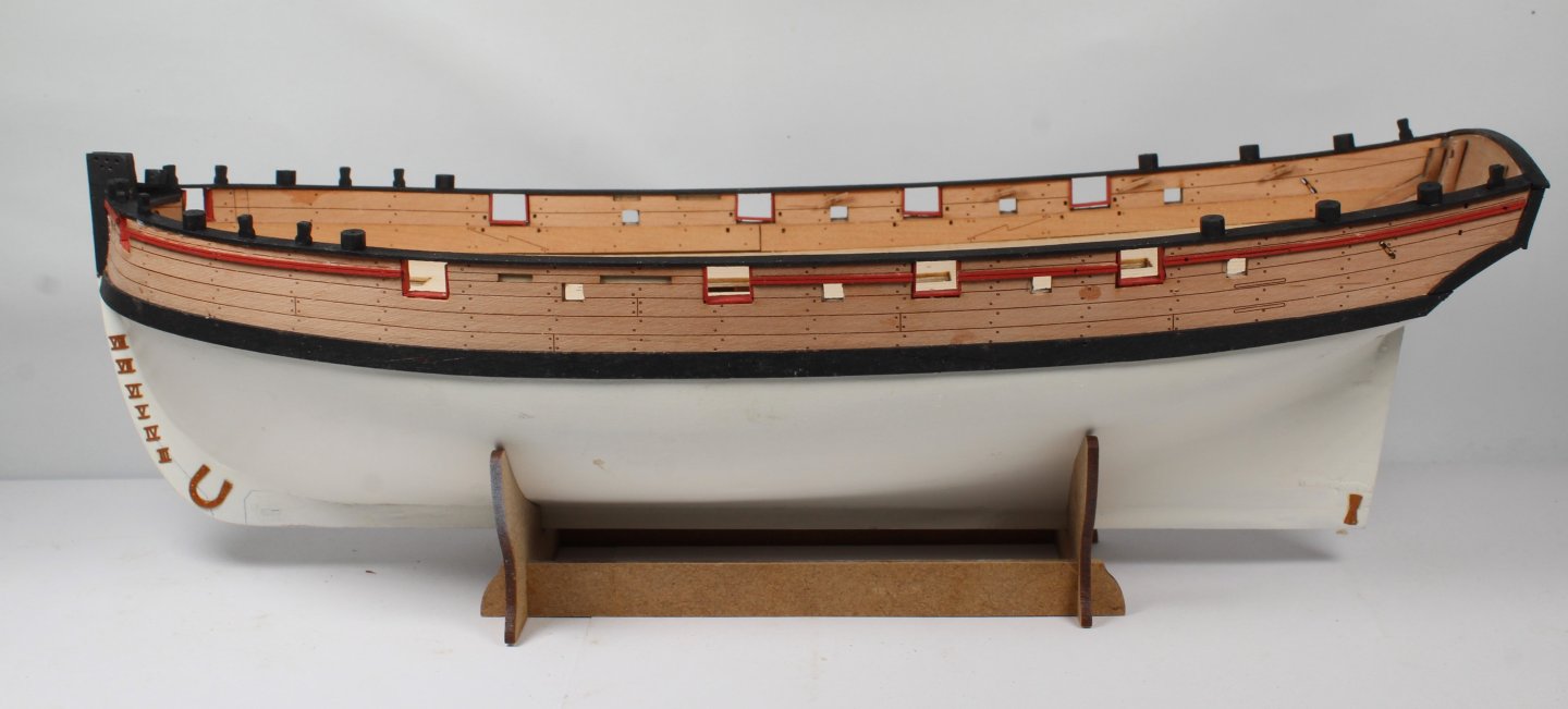
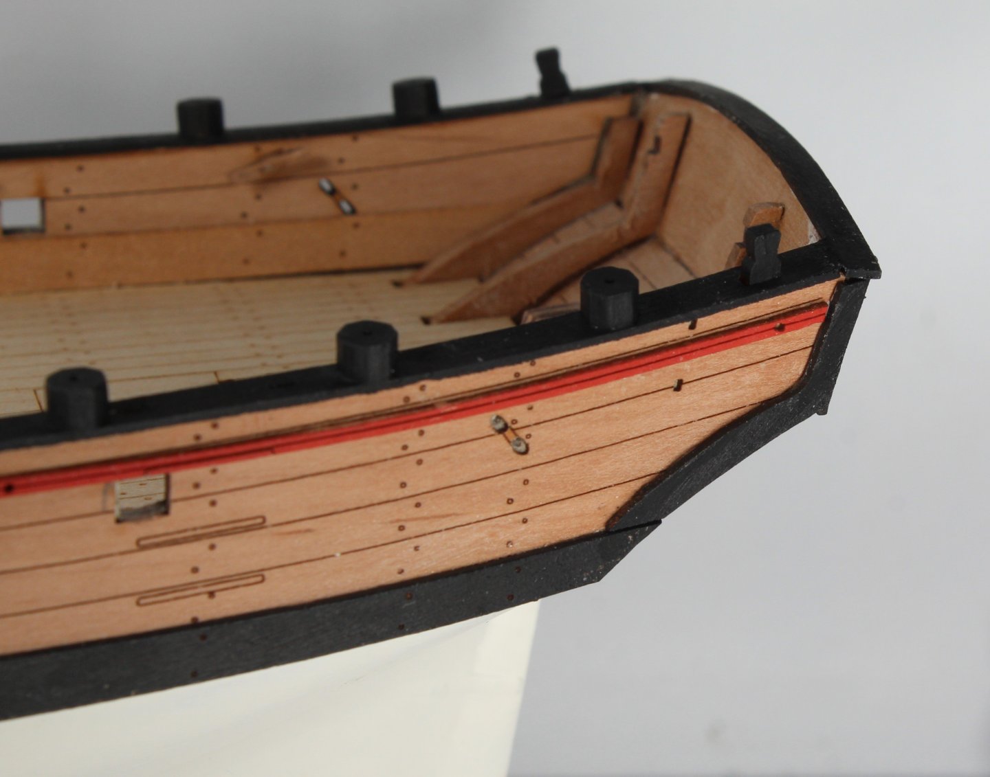
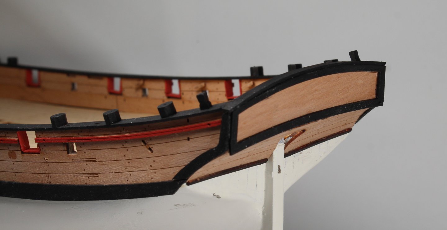
I have now completed all the work on my Sherbourne build which is now displayed as a naval board style model. I do have the option to expand to a fully rigged model sometime in the future. However for the next few months I will be building the Harpy which I am very much looking forward to starting as it looks to be another impressive Vanguard Model. It has been a fun project where I have experimented with some different build methods, which was my intention with this build. My main objective was to try out some different planking methods and I believe I have finally got to grips with how to plank, albeit there is still much more work required to get neater results. The use of the lateral (Chuck's) bending method is certainly the best method for planking around the bow to avoid the dreaded clinker effect. Appling twists to planks when planking toward to the stern was an eye opener and yielded amazing results compared with all of my previous builds, thanks to @Jase for demonstrating this on his YouTube channel Sherbourne build videos. Taking more time and care when assembling the hull items ensured that the various hull and deck items lined up and were installed without any major issues. @chris watton has produced an amazing kit and I am very happy to continue to support his Vanguard Model enterprise buy buying and building the models from his expanding range, with kits suited to all levels from novice to master shipwright. Here is a selection of photos of my completed Sherbourne Naval Board Style build. I have attached some photos of some of my other Vanguard Model builds scattered around the house. The Indy is missing from the photos as someone made an offer to buy which I simply could not refuse to accept so she is now in place where she can be openly displayed and admired by others. A couple of others have been damaged and have been consigned to Davy Jones Locker.


- 43 replies
-
- 14
-

-
-

-
- Vanguard Models
- Sherbourne
- (and 1 more)
-
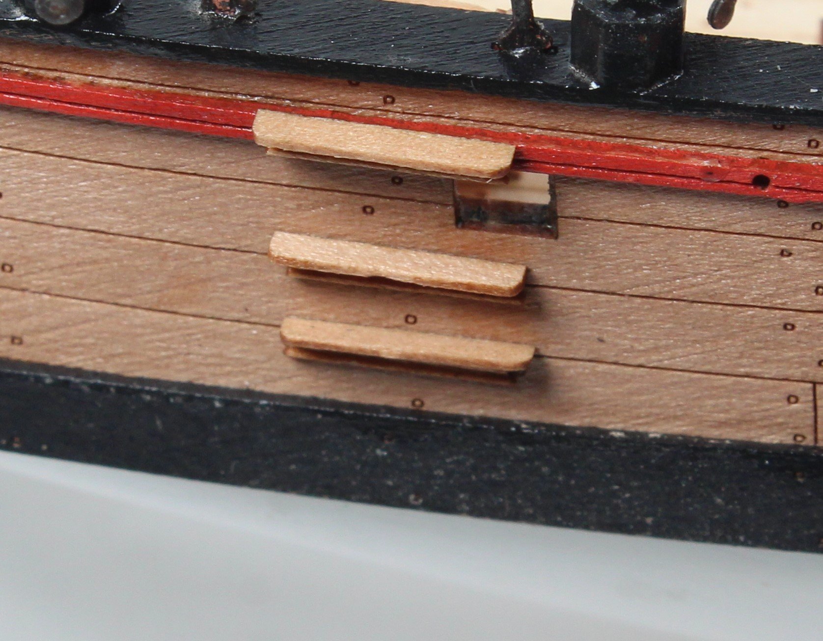
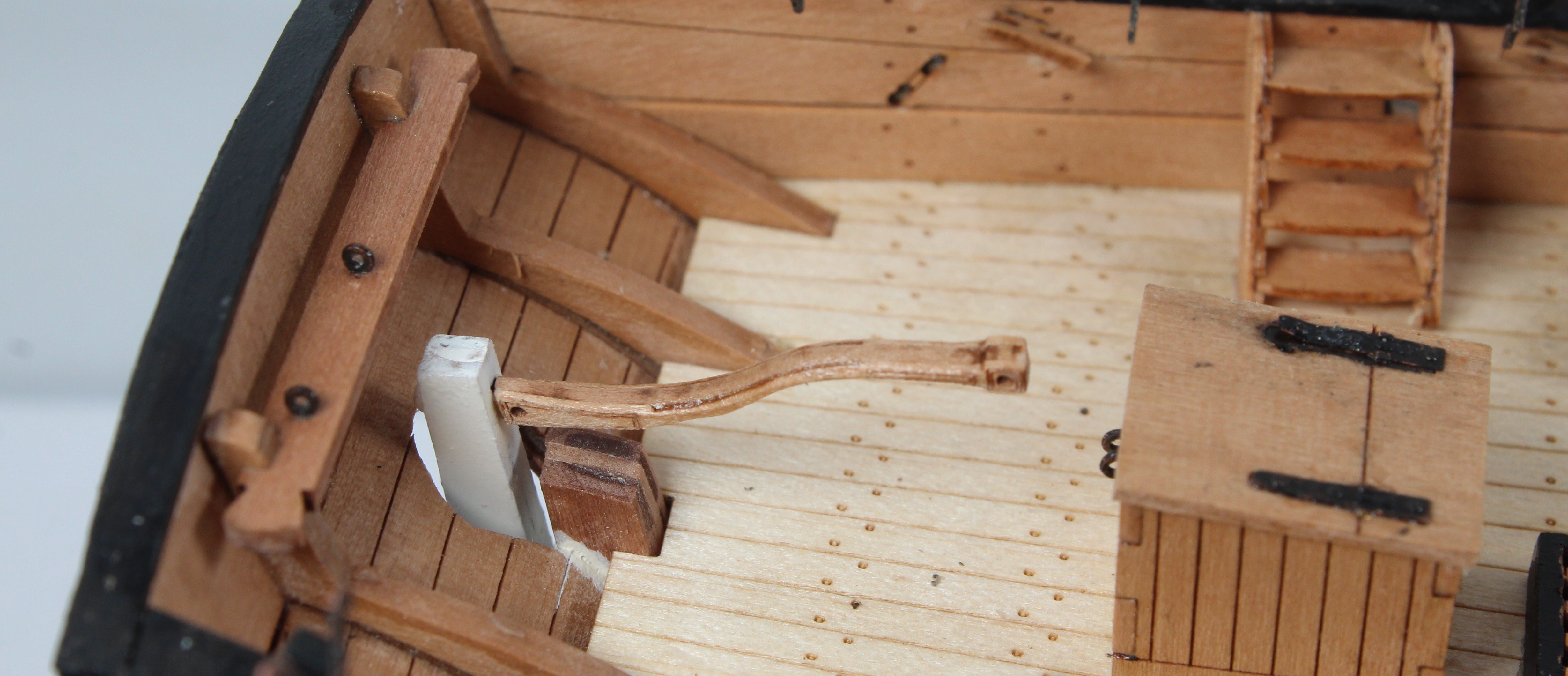
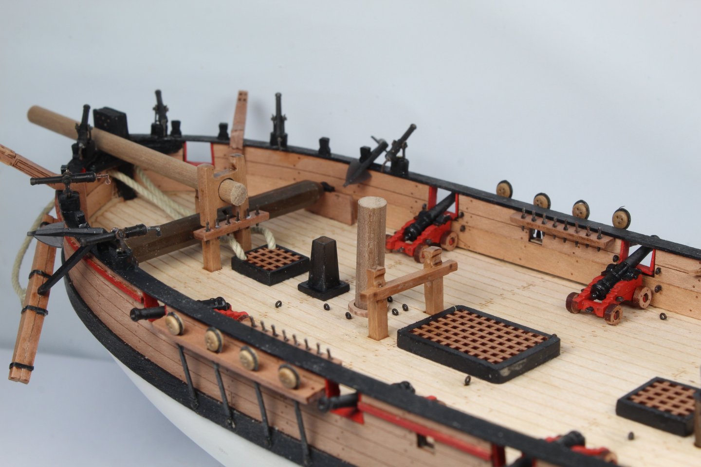
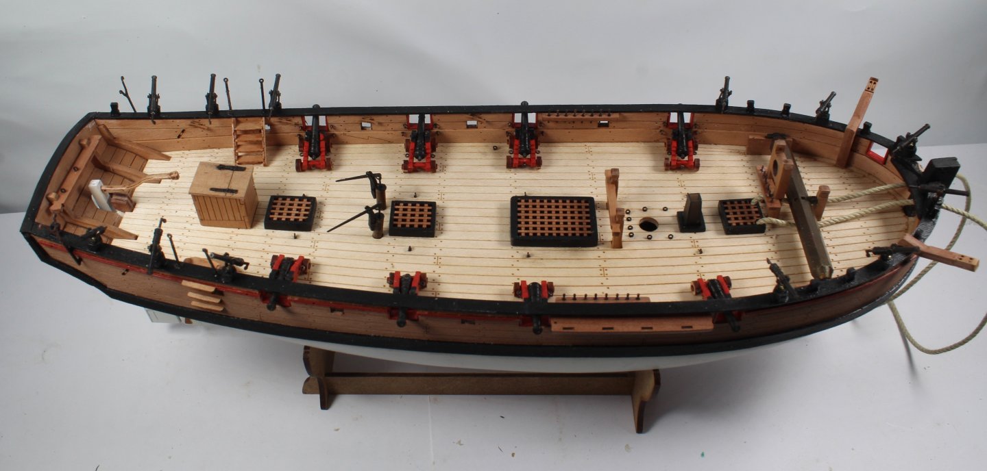
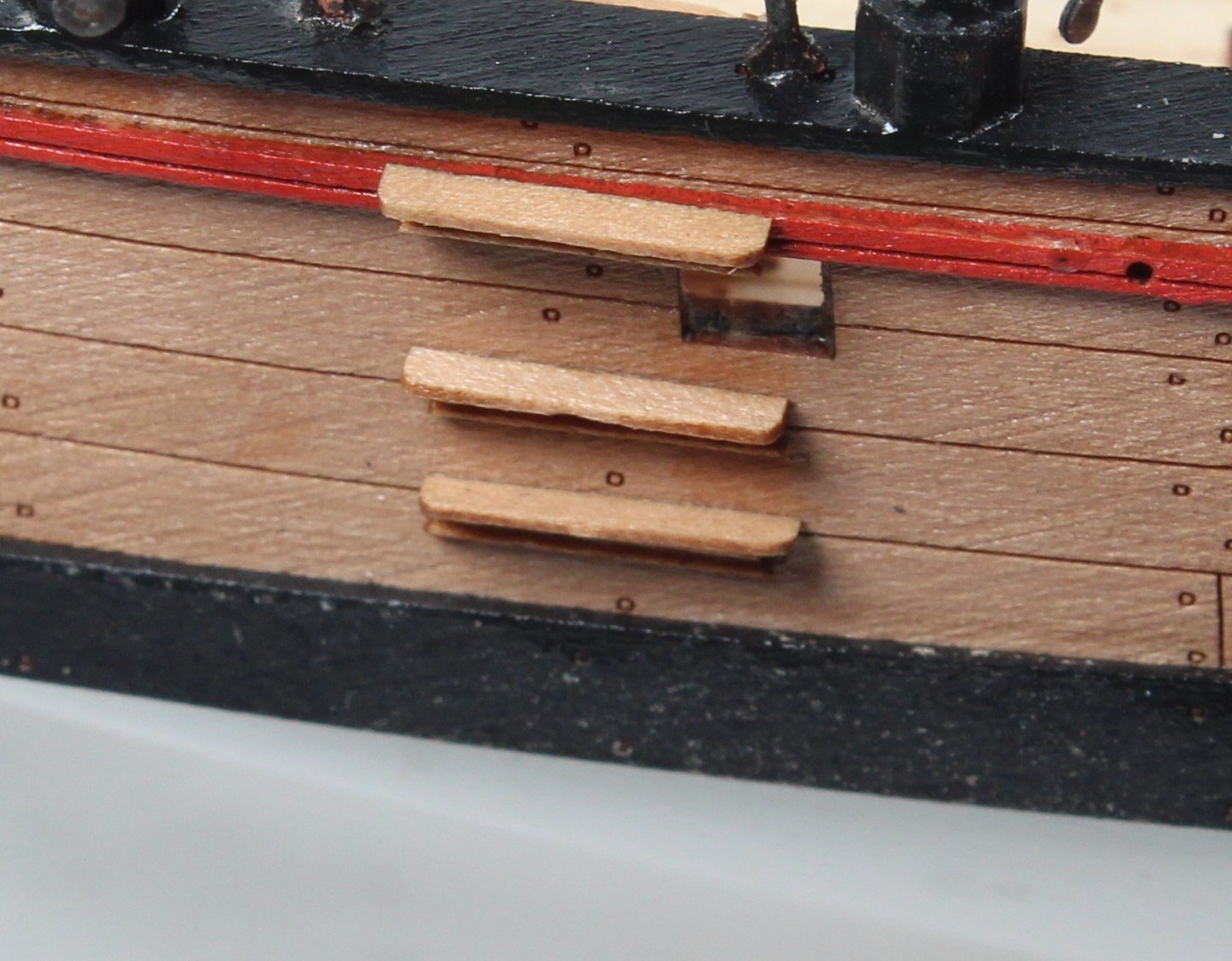
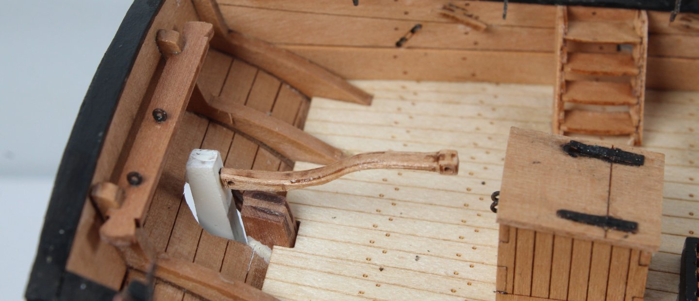
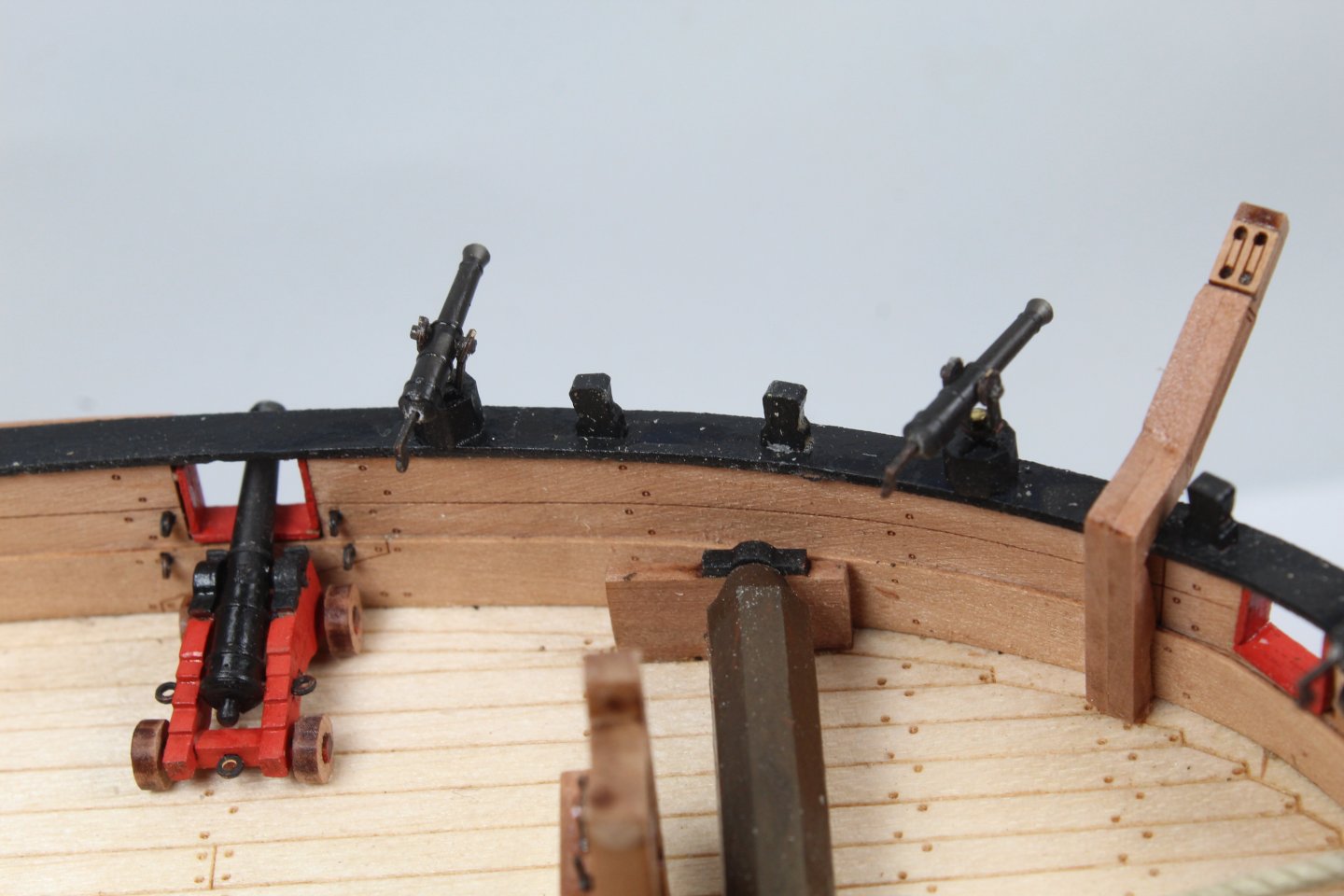
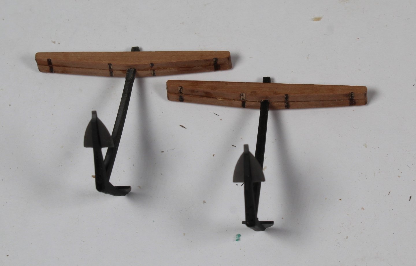
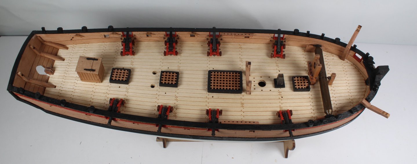
The Sherbourne hull and deck work is now completed, apart from a little bit of tiding up. The next stage would be to make the various masts and yards and then to rig the model. I bought this model to try out some different planking methods and to fill in time before the Harpy kit was released. Therefore I might just add dowel stubs for the main mast and bowsprit akin to a naval board style build so I can then make a start on the Harpy build. Photos of the Sherbourne Current Build Status The outer steps have been added. These are very fiddle to assembly. The ladders have also been installed. The ladder stanchions needs a bit of works to ensure they are correctly aligned and touched up with black paint. The tiller arm has been added to the rudder. Rope for the two anchors have been added. The swivel guns have been added. I did struggle to build these. One problem I had was being able to glue the locating pin to the PE base. I was using CA glue but the pins did not seem to adhere. Once the guns were added it was difficult to keep some guns in a set position. I will probably adjust and use some glue to hold the guns in place. The channels have been added. I will add the deadeyes and chainplates. Belaying pins have been added. The anchors have been assembled, noting the black card strips still have to be added. They are normally added to the ship once the ship has been rigged. I am not sure what I will do at the the moment.


- 43 replies
-
- 8
-
-
- Vanguard Models
- Sherbourne
- (and 1 more)
-
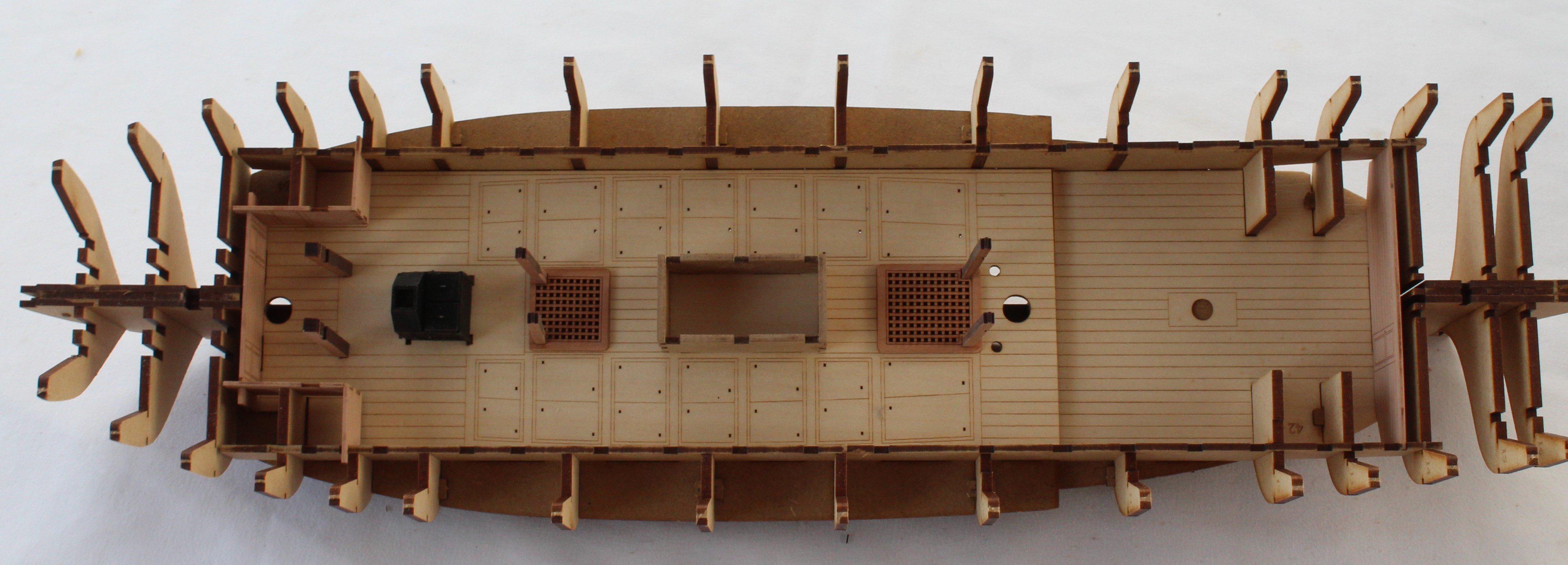
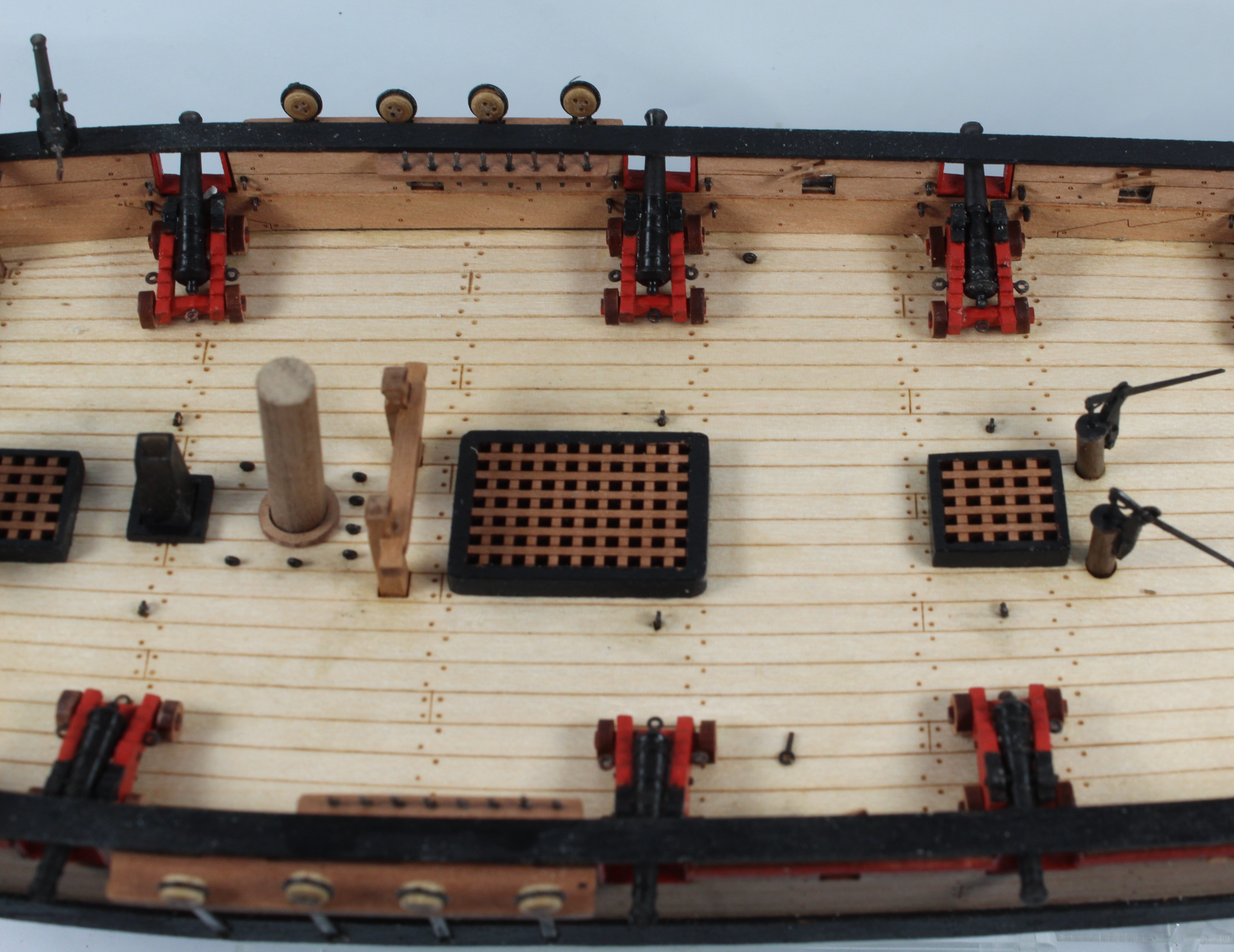
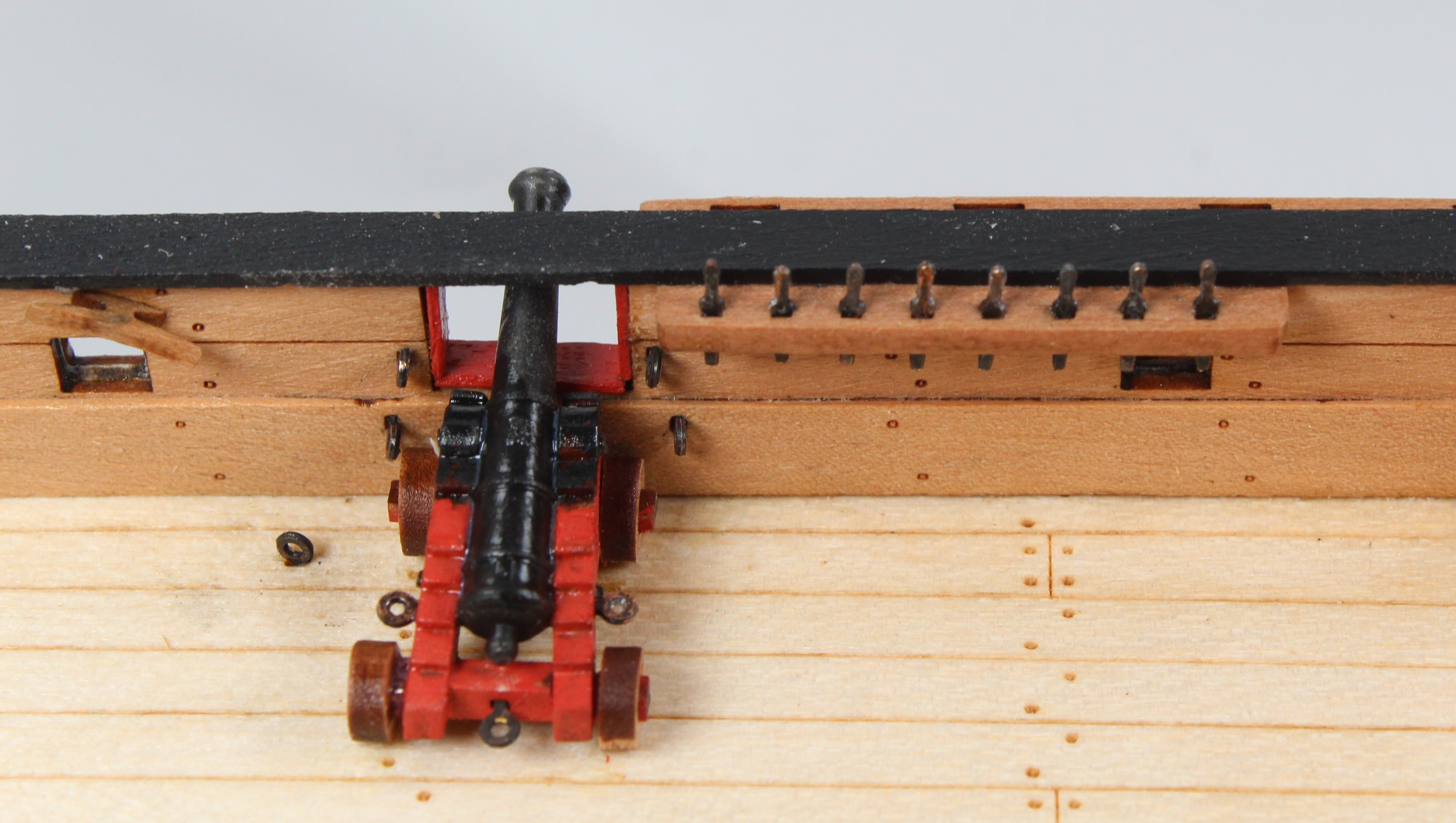
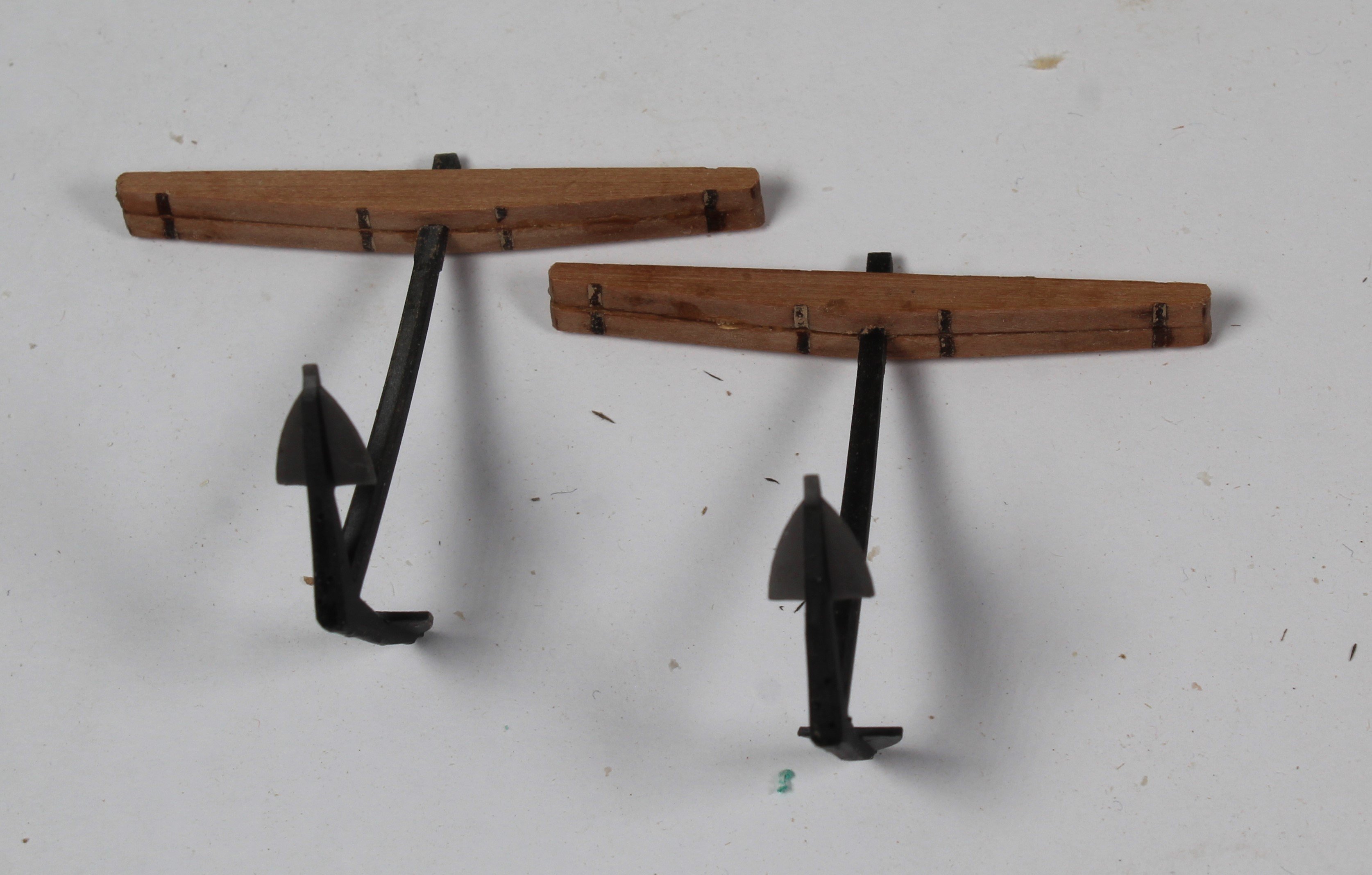
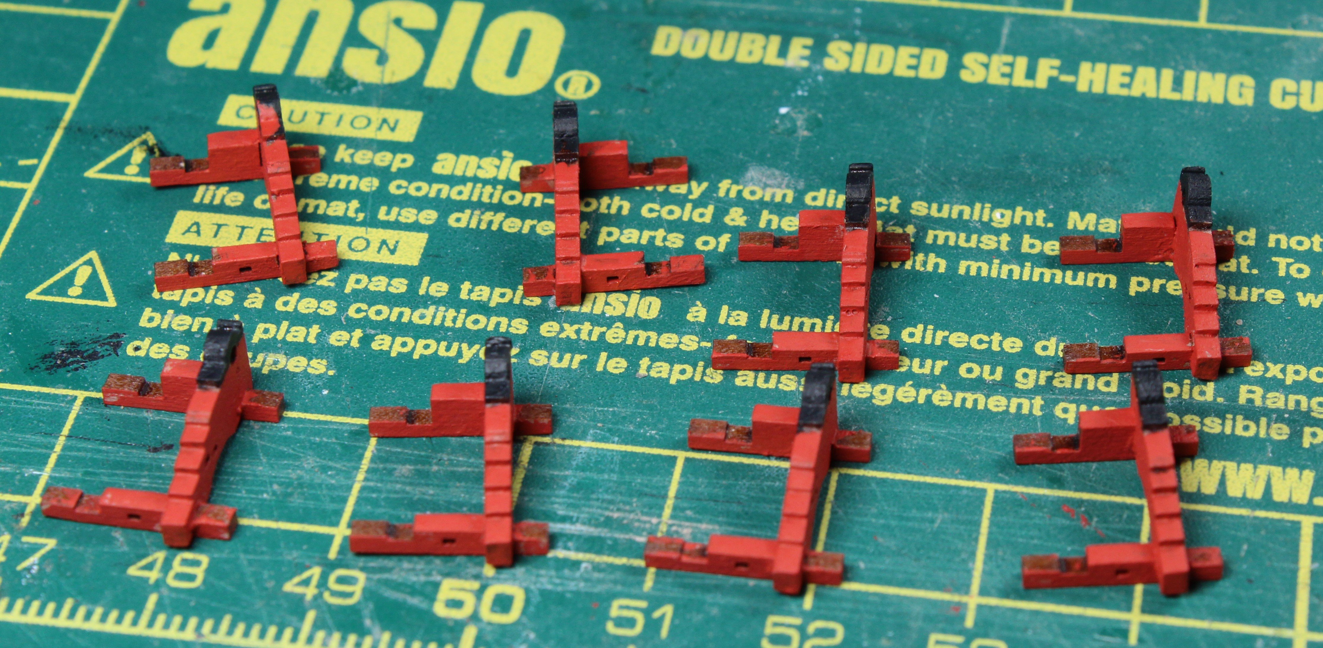
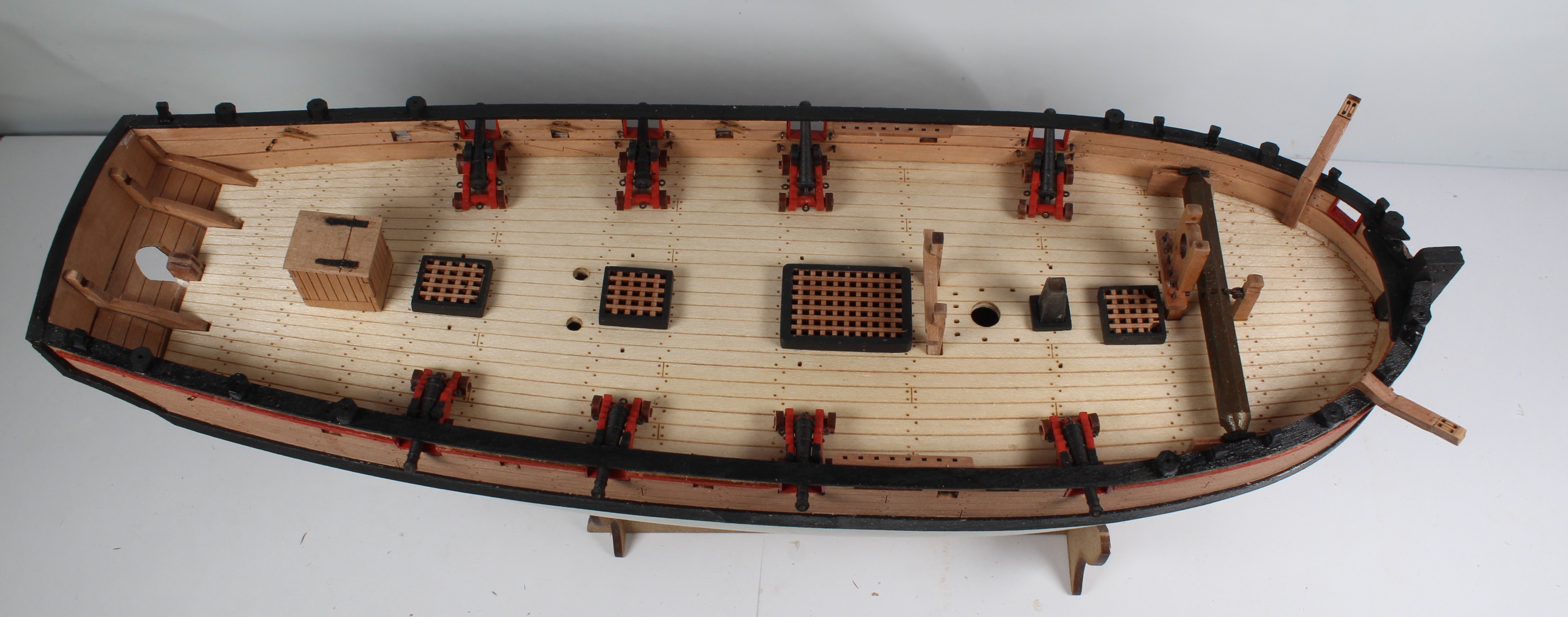
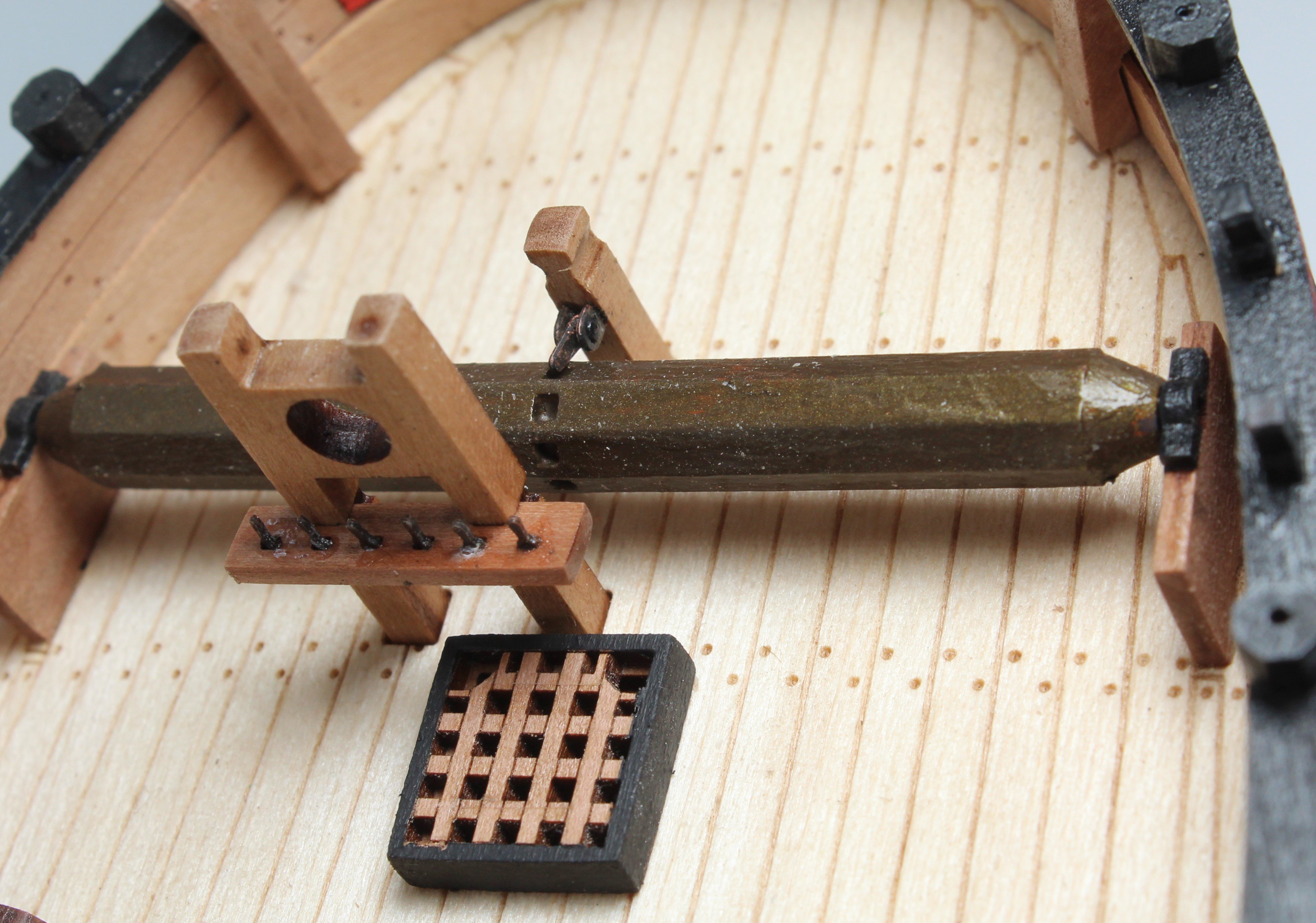
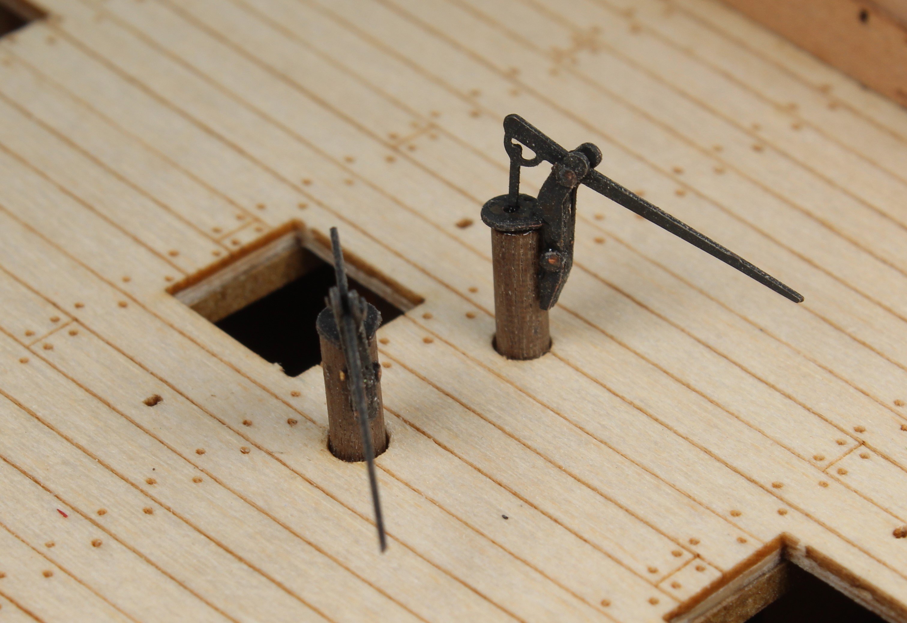
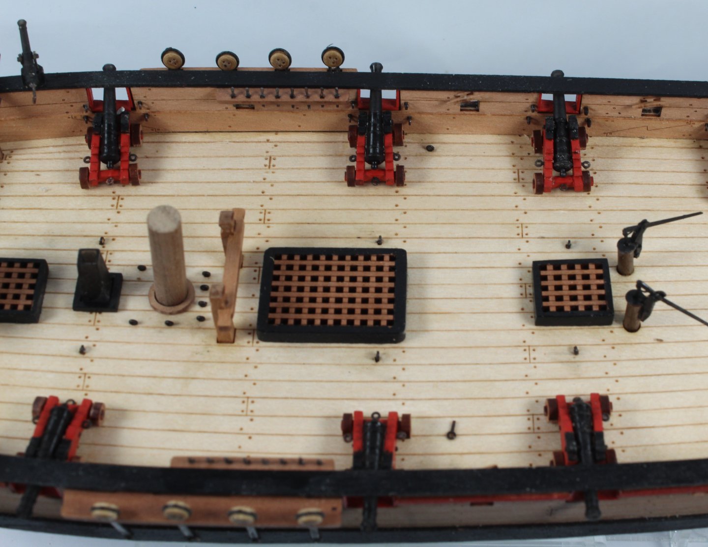
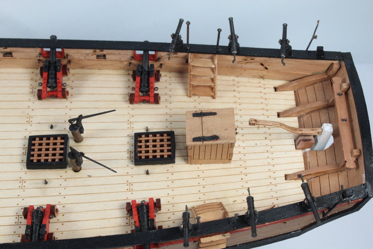
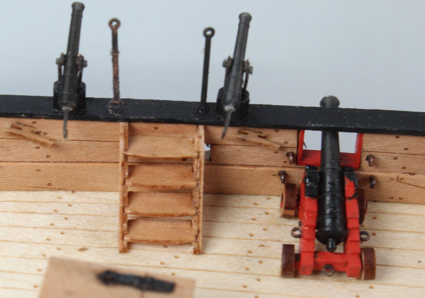
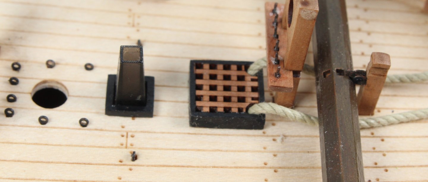
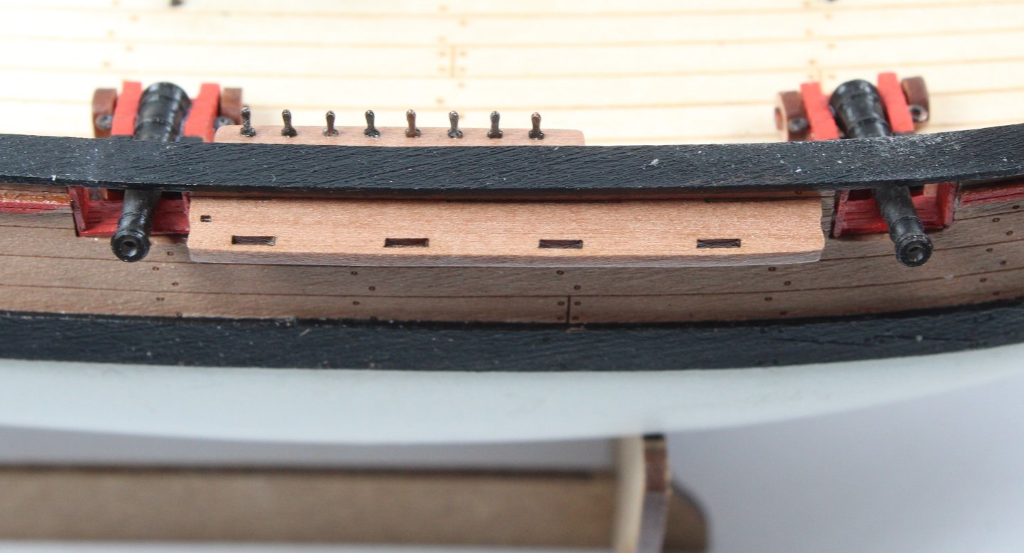
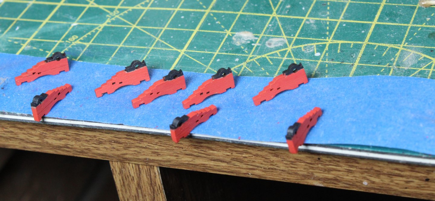
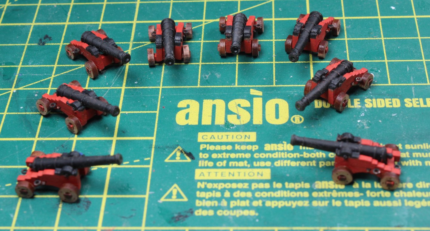
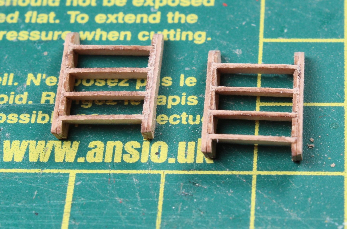
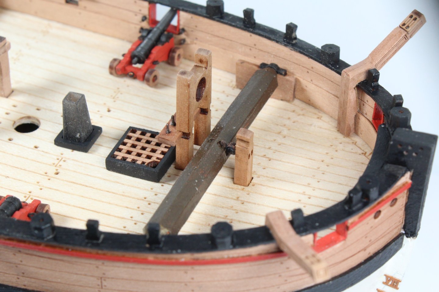
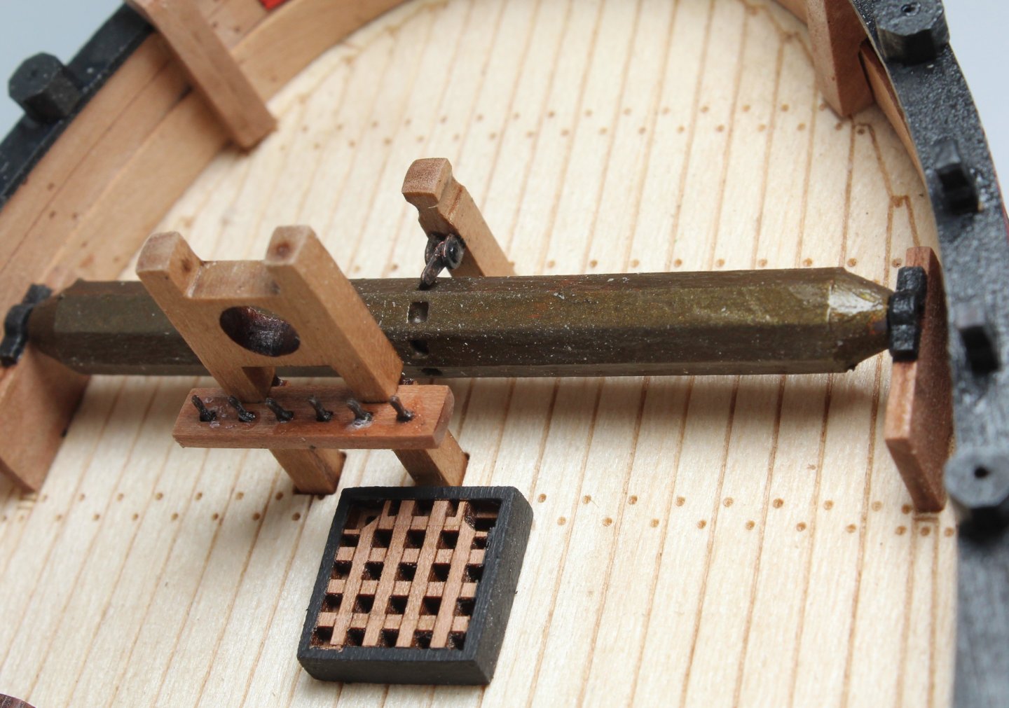
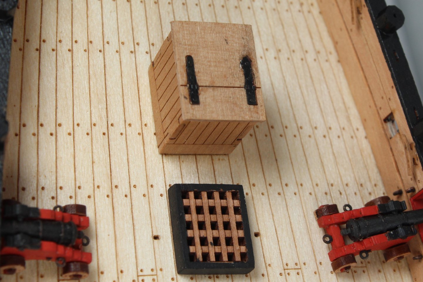
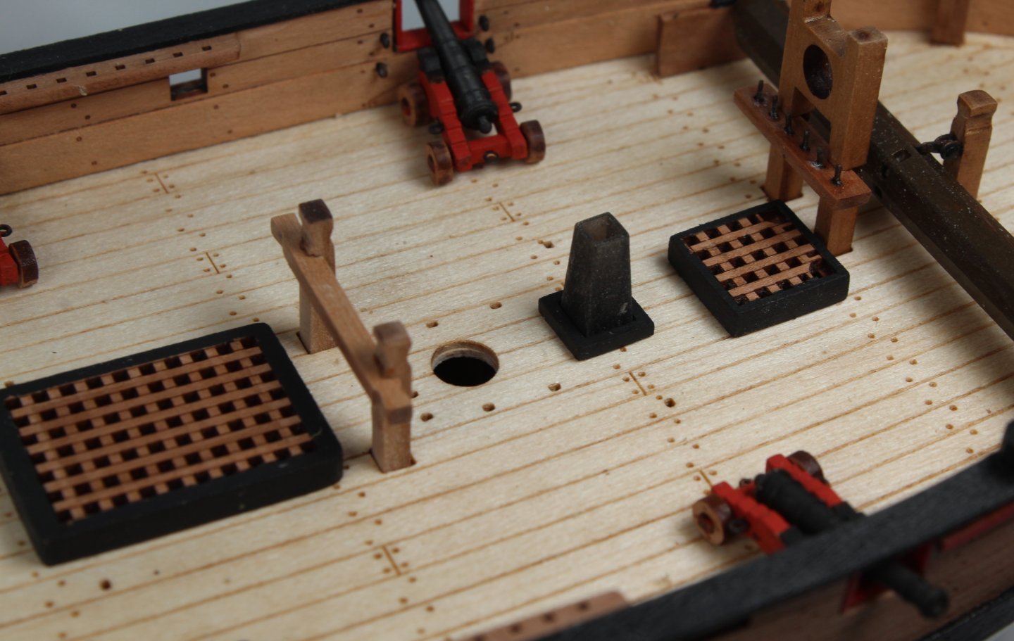
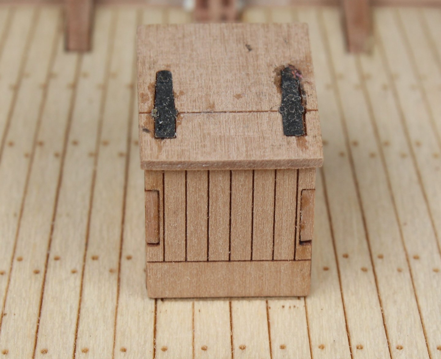
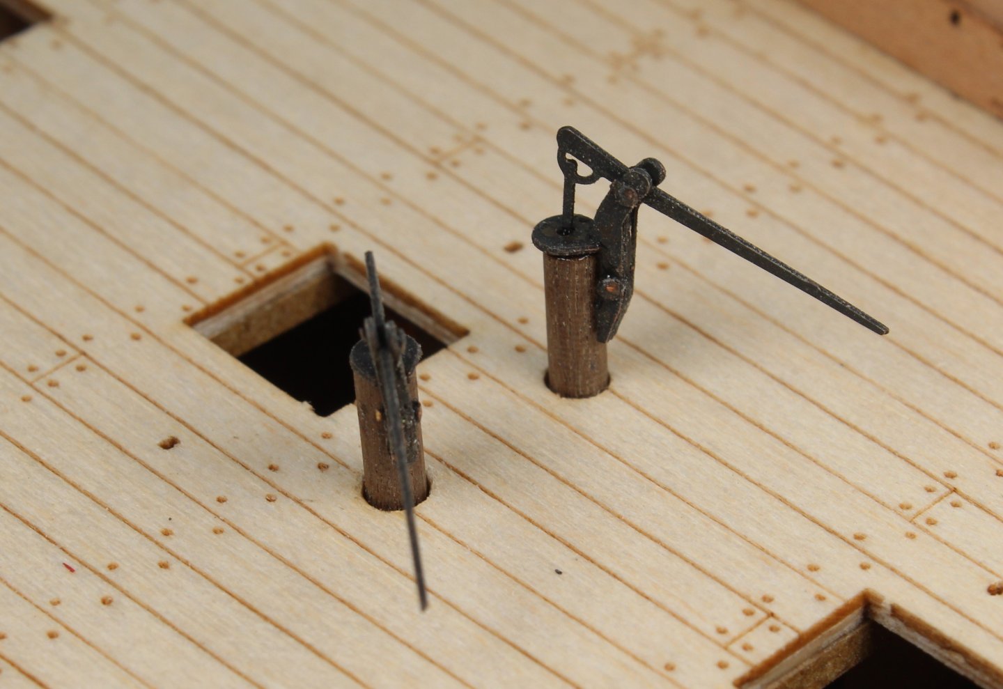
Stage 19 – Deck Work Deck Work - Cannons Build Steps I decided to paint the carriages red, with the top cannon section black. This is shown in the first two photos. The assembly task was then completed without any issues as can be seen in the third photo. Time Taken 120 mins Deck Work - Ladders Build Steps The two ladders have also been assembled but they have not been fitted to the deck. This was a straightforward task. I glued one rung to the top position on one side of the ladder. Once the glue had taken a firm grip another run was added to the bottom position. Once the glue had taken a firm grip the other ladder side was added. Once the glue had time grip the other rungs were added and finally the outer patterns were added. Time Taken 10 mins Deck Work – Windlass, Bitts, Gratings & Companionway Build Steps The windlass winch drum was painted brown, and the two sides tops were painted black. The windlass assembly was then added to the deck. The PE parts were added to the pawl post and then the post was added to the deck. I tidied up the companionway and then glued it to the deck. I decided to paint grating surrounds black. In the following photos they are placed on the deck but are not glued in place. The same is true with the cannons. Time Taken 30 mins


- 43 replies
-
- 6
-
-
- Vanguard Models
- Sherbourne
- (and 1 more)
-
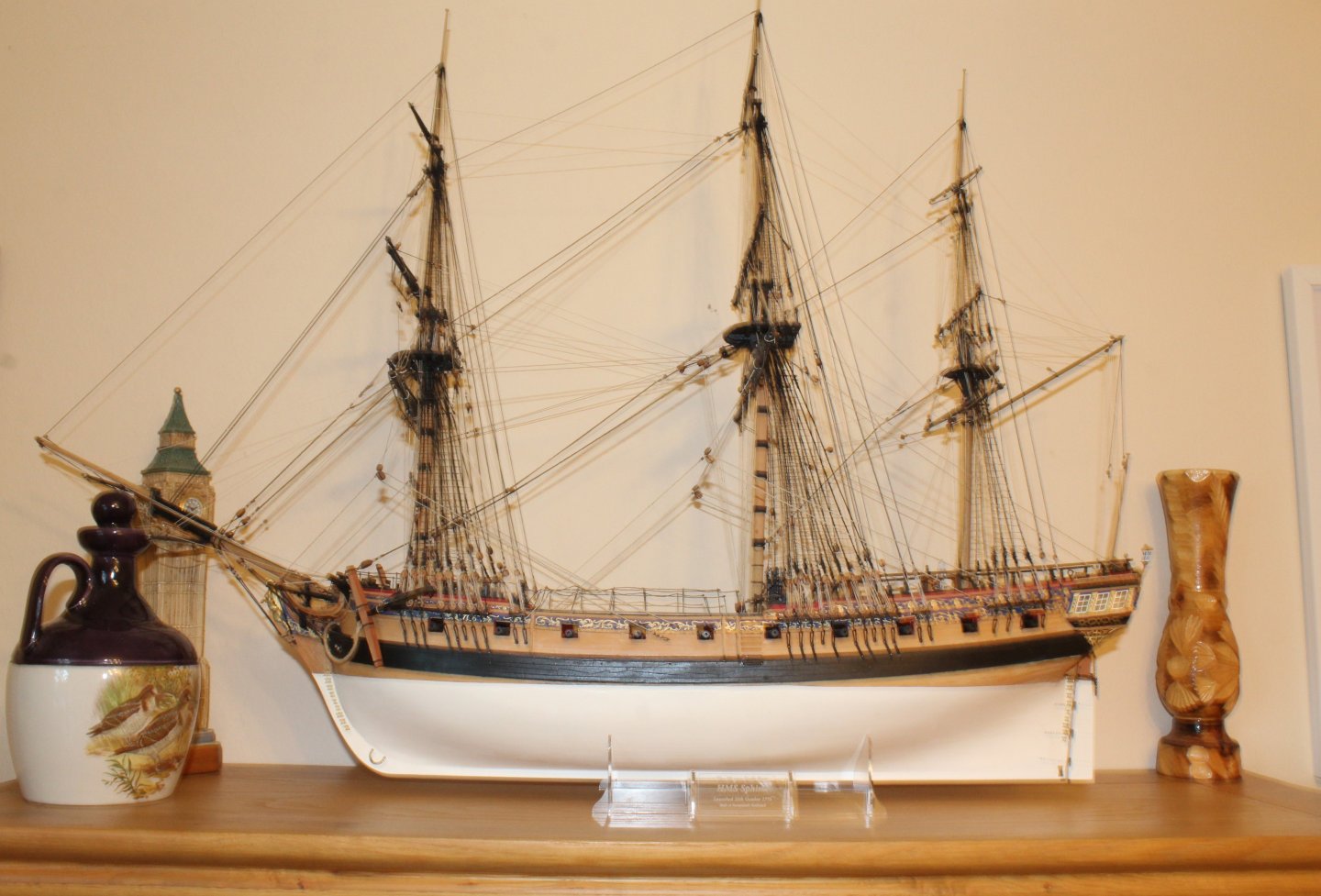
Hi. No worries. This is just a filler project to experiment with some planking methods. I have previously built models such as the Indy, DOK and Sphinx.
- 43 replies
-
- 5
-
-
- Vanguard Models
- Sherbourne
- (and 1 more)
-
Thanks, I have built plenty of these cannons in the past and I always test fit them during the assembly phase. The best advice is to assembly and then carefully slide the wedge with the cannon in situ to get the desired cannon angle. Wood glue will keep the wedge in place once aligned. I have bought some items which could, when fitted, replicate the wedge handle.
- 43 replies
-
- 3
-
-
- Vanguard Models
- Sherbourne
- (and 1 more)
-
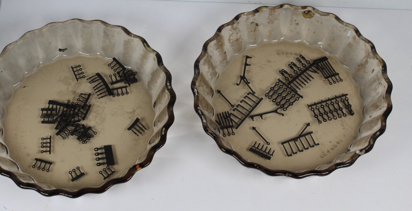
Stage 19 – Deck Work Hull Construction – Final Tasks Build Steps My original plan was to install all the gun port eyebolts once they had been chemically blackened. As I was going to blacken the eyebolts, I decided I might as well go ahead and blacken all the various PE parts required for the deck fitted items. The process I use to blacken the PE parts works well as is as follows: a) Soak the parts in acetone for a few minutes then place on paper towel to dry off b) Soak the parts in hot soapy water for a few minutes c) Rinse the parts in clean hot water and then place on paper towel to dry off d) Place the parts in a blackening solution. I use Metal Burnishing Fluid AK Interactive AK-159 e) Remove the blackened parts from the solution and dry on a paper towel. Time Taken 30 mins Hull Construction – Final Tasks Build Steps 74 - 87 The following deck items were then assembled: a) Companionway, a bit of cleaning up required and I might paint the assembly b) Catheads c) Tiller Arm d) Hand Pumps, a bit of cleaning up required. The two belay pin racks were installed. My next tasks will be to: a) Assembly the 8 off cannons b) Fit all the gun port and deck eyebolts c) Assembly and install the two ladders d) Add the steps and PE stanchions to the hull e) Assembly the winch. f) Fit all the deck parts g) Add channels to hull Once all that has been done the deck work will be completed. I am in two minds weather to then progress with the mast and yard manufacture and rigging or to put the build on hold as I really want to start work on the Harpy. Time Taken 60 mins

- 43 replies
-
- 6
-
-
- Vanguard Models
- Sherbourne
- (and 1 more)
-
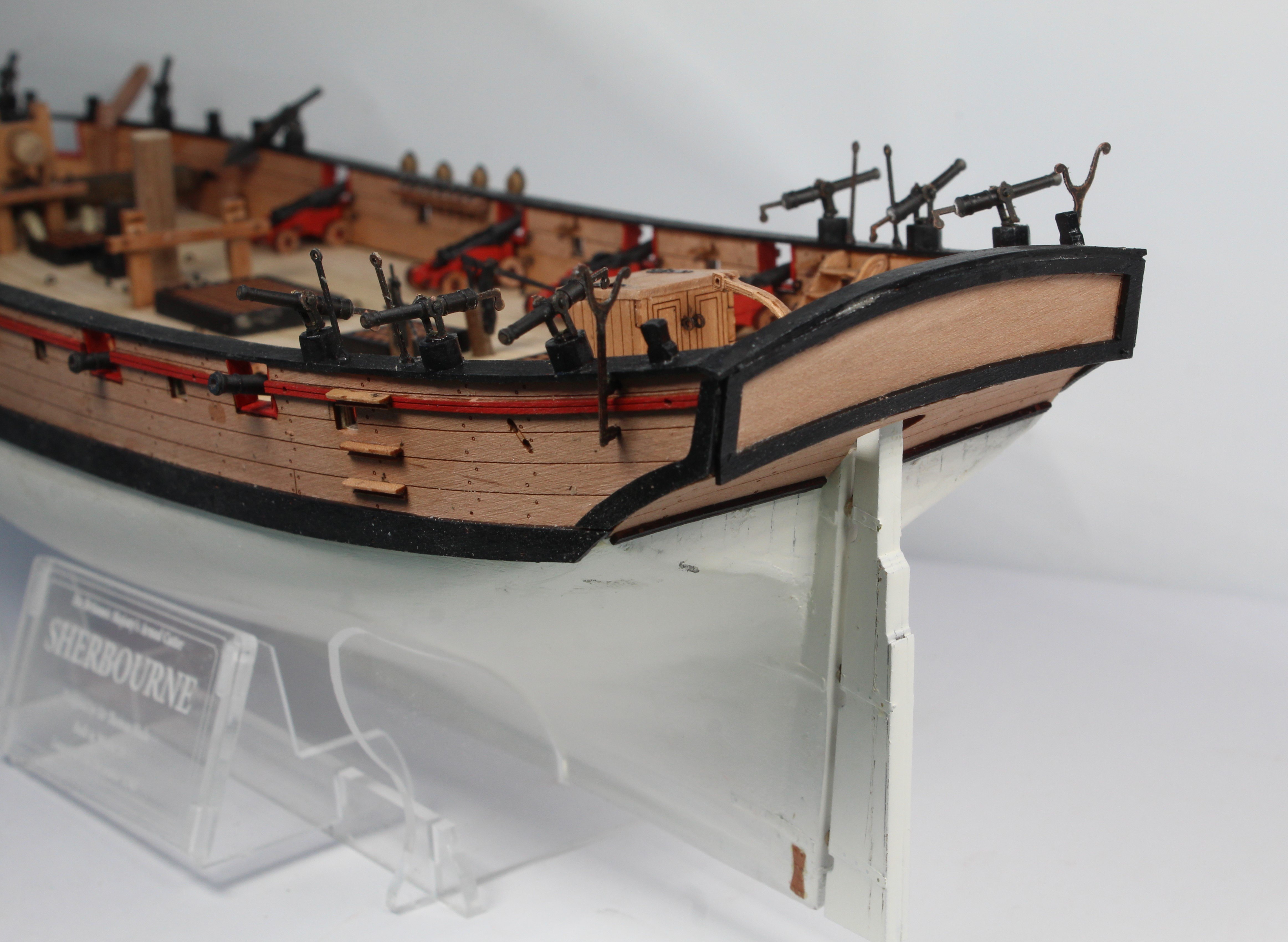
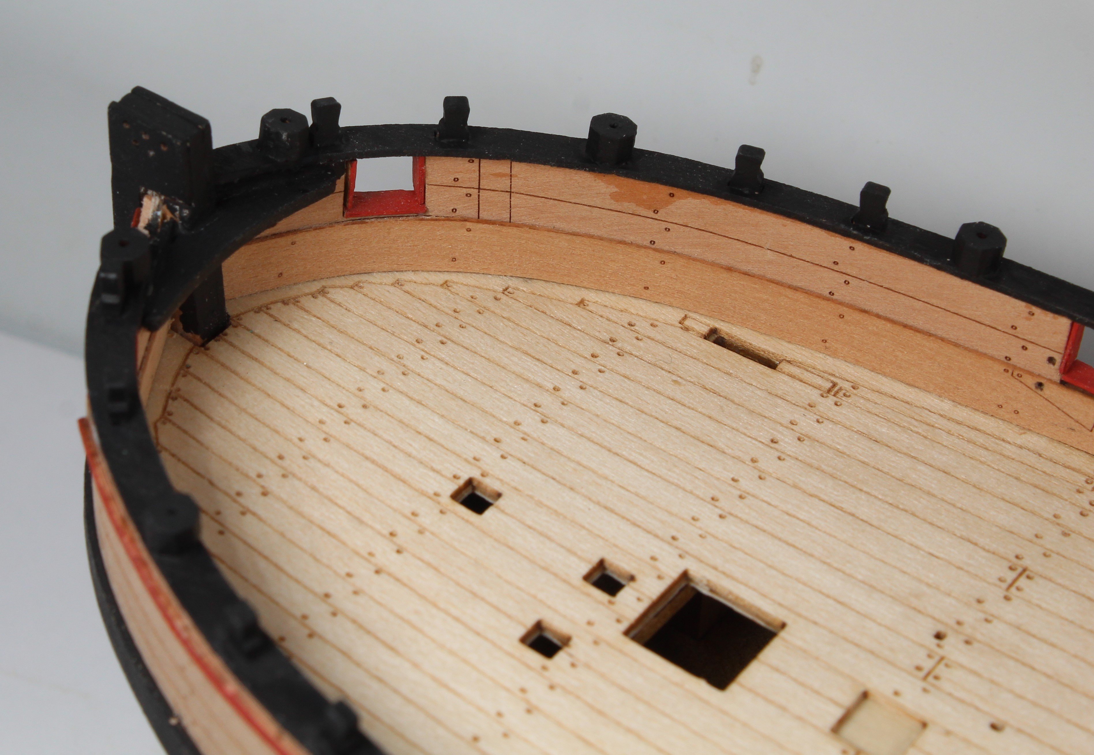
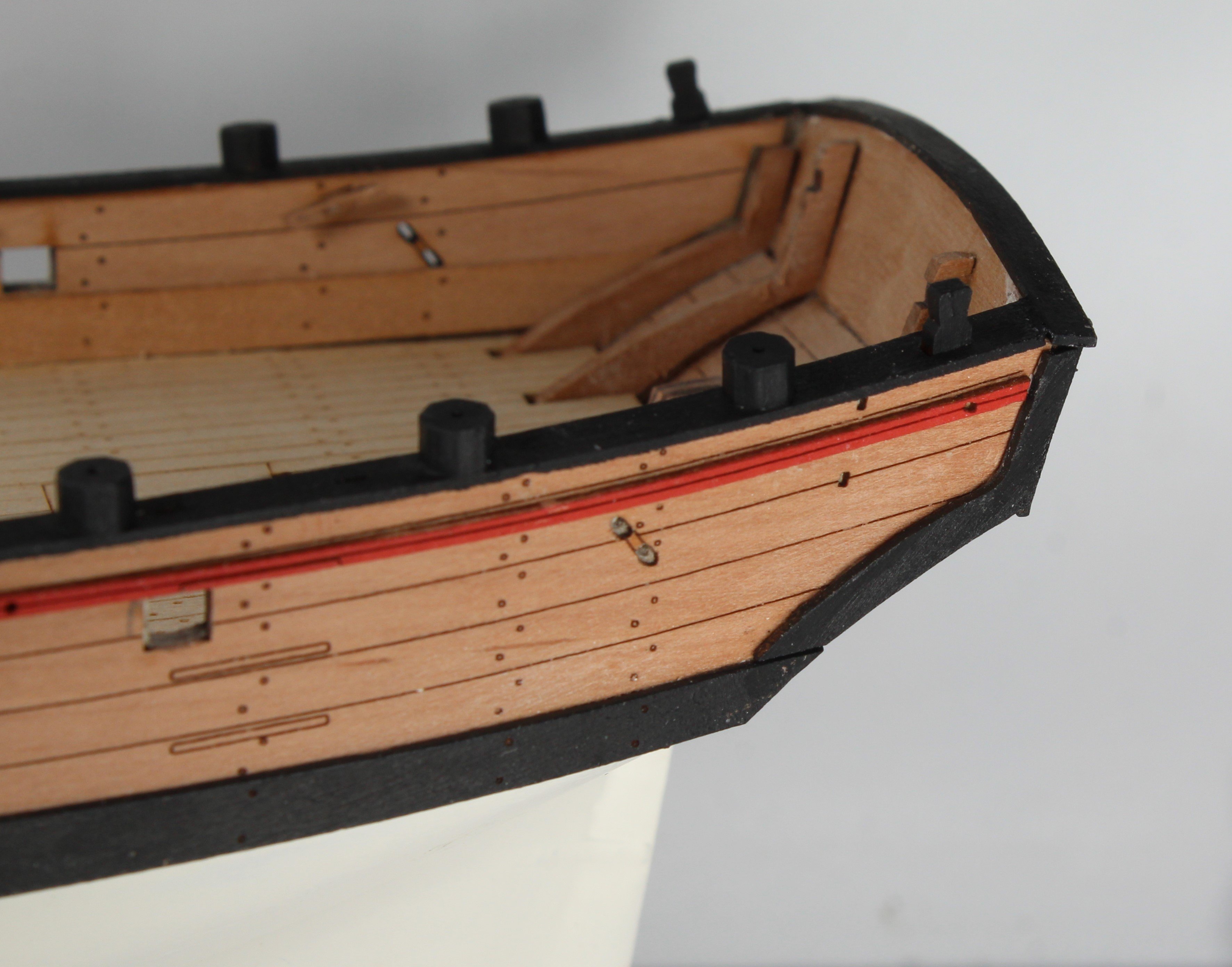
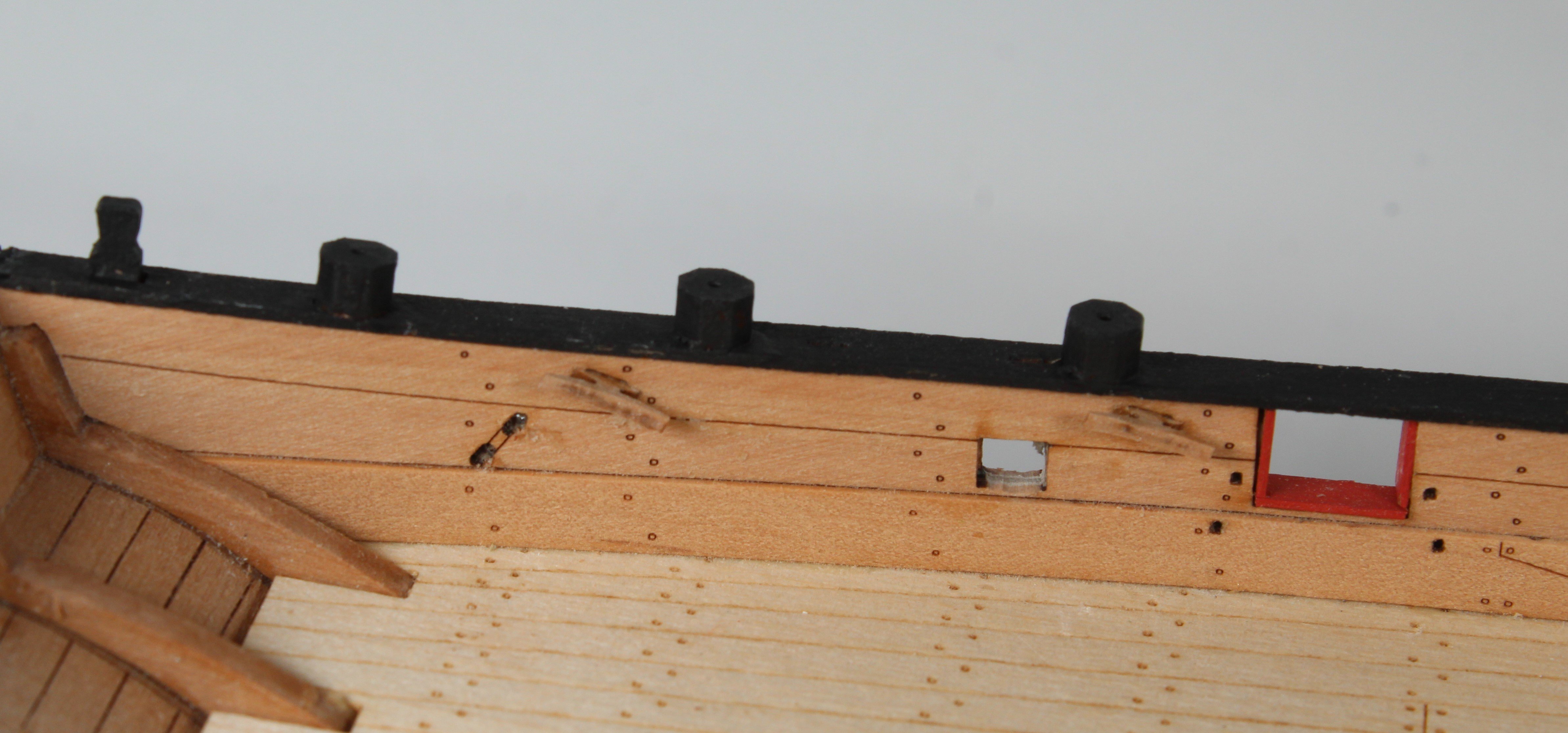
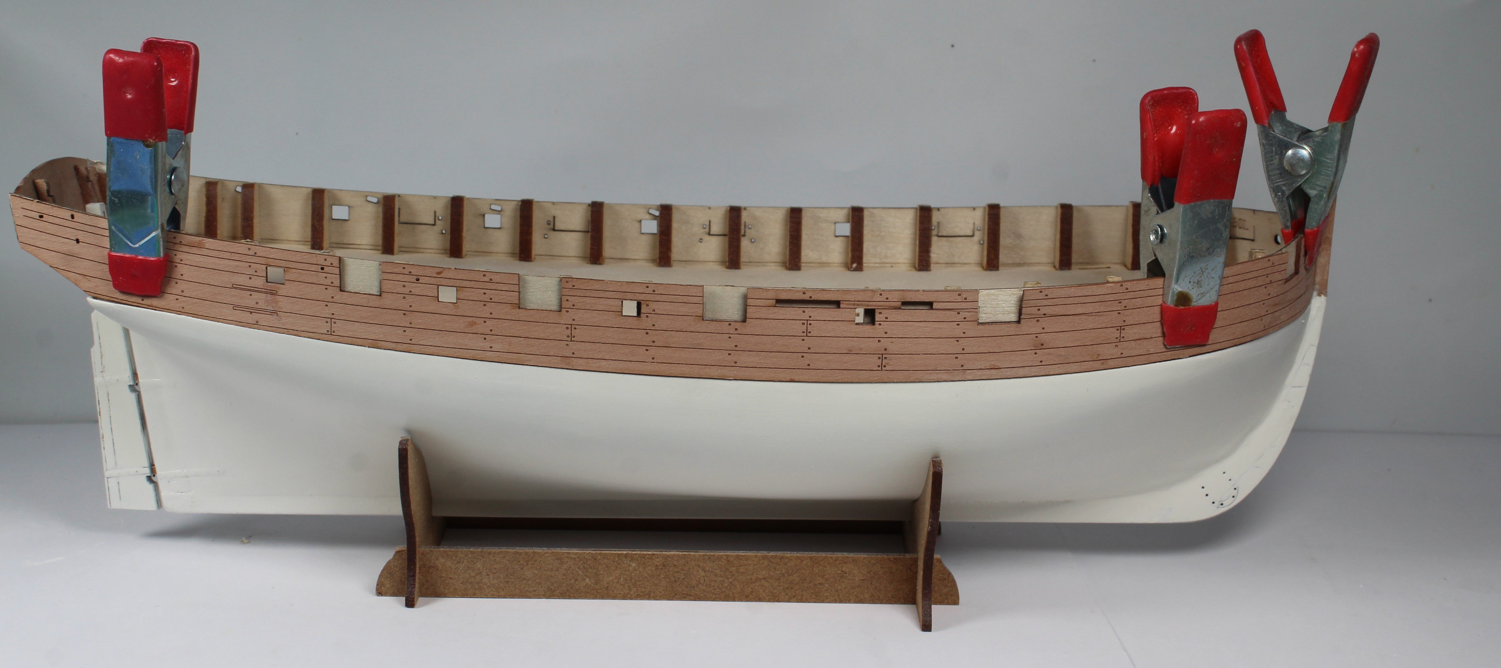
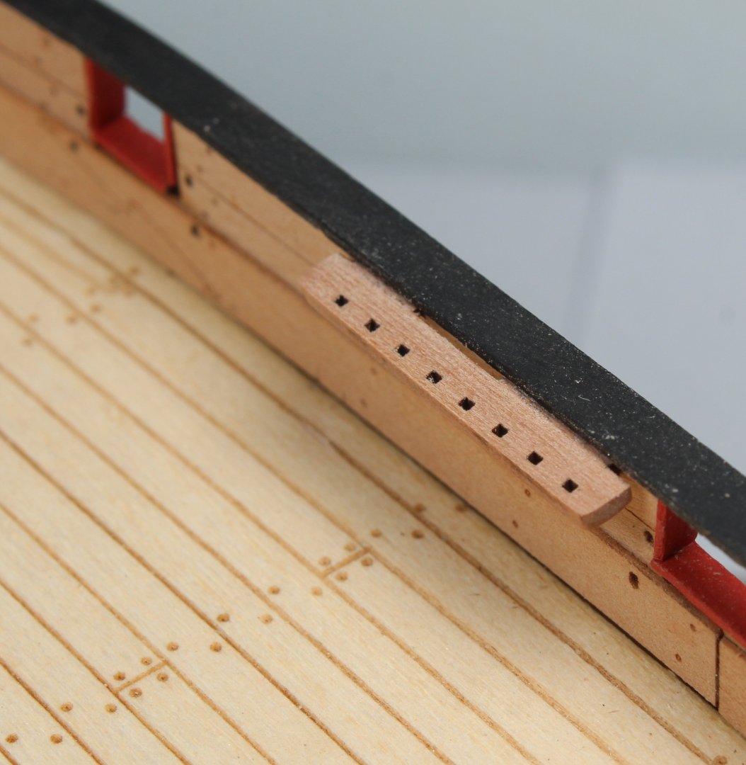
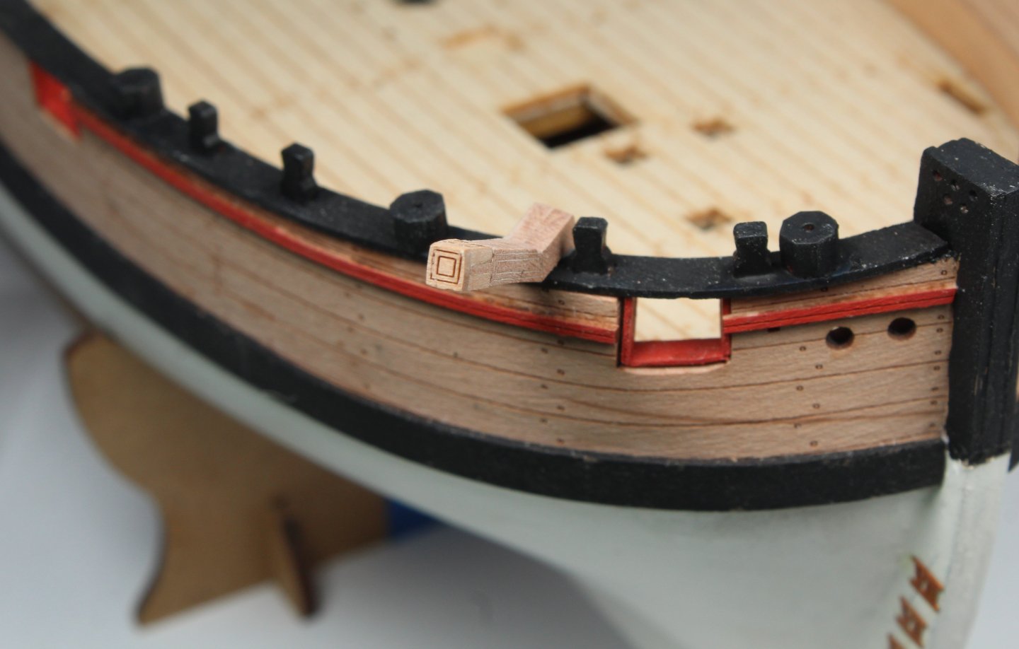
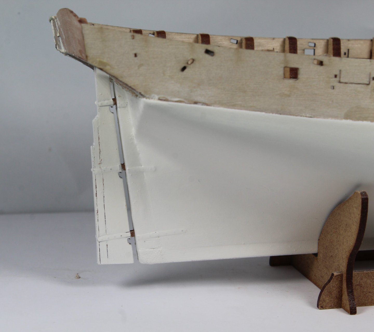
Stage 18 – Completion of Hull Construction Phase Hull Construction – Final Tasks Build Steps 64-73 A lot of work has been completed and the hull build phase is now complete and I am ready to move on to adding the deck fittings. The completed tasks are: a) Cutting the gun port openings. After sanding the cut edges, I decided to add some gun port linings using some spare material. I painted the lining red. b) The bow keel was glued in place and painted black. c) The gunwale were painted black and then glued in place. d) The swivel gun posts and timberheads were glued in place on top og the gunwales. e) The stern side timers and top piece were added to the stern. f) The stern transom rail and stern counter rails were painted black and then added. g) The upper support rails were painted red and then glued in place. h) The cleats were added to the inner bulwarks. i) I test fitted eyebolts in all the holes on the inner bulwarks and deck. The eyebolts still need to be chemically blackened before they are glued in place. Time Taken 180 mins Current Build Status Photos I have added some photos showing the current status of the build.

- 43 replies
-
- 7
-
-
- Vanguard Models
- Sherbourne
- (and 1 more)
-
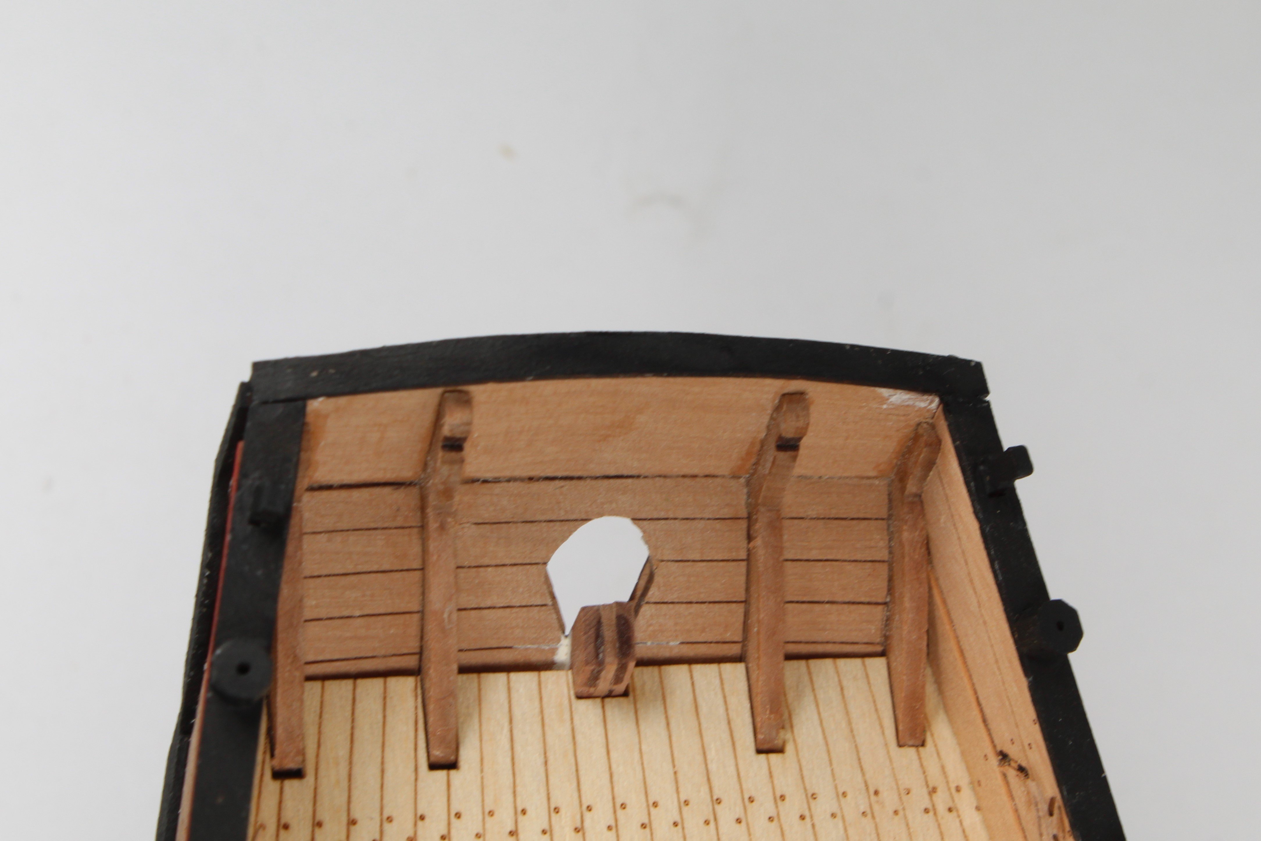
Stage 15 – Laser Engraved Deck Installation Hull Construction – Laser Deck Installation Build Steps 53-55 The excess bulkhead tab material was removed, and the remnants were then sanded smooth. The laser engraved deck was then test fitted, after the laser char had been removed, from the outer edges. The deck was a good fit and I also checked the various deck items would locate in the various apertures. Plenty of wood glue was then brushed on to the deck base and the laser engraved deck was fitted. Plenty of clamps were then used to keep the deck in contact with the base while the glue cured. Time Taken 20 mins Stage 16 – Fitting Inner Bulwark Patterns Hull Construction – Inner Bulwark Patterns Installation Build Steps 56-61 There are two inner bulwarks per side and the front patterns were soaked in warm water for a few minutes and then clamped to the hull. Once the patterns had fully dried out they were test fitted and did require a bit of sanding on the leading edges before I was happy with the alignment. Plenty of wood glue was then brushed on and the inner bulwark patterns were carefully aligned and clamped. As can be seen in the attached photos I did dry fit some eyebolts to ensure the patterns were correctly aligned. Time Taken 30 mins Stage 17 – Fitting Spirketting Patterns Hull Construction – Spirketting Patterns Build Steps 62-63 There are two spirketting patterns per side. These patterns were test fitted, and they did require a bit of sanding on the leading edges before I was happy with the alignment. Plenty of wood glue was then brushed on the patterns and they were carefully aligned and clamped. As can be seen in the attached photos I did dry fit some eyebolts to ensure these patterns were correctly aligned. Next I sanded the top edges of the bulwarks flat and added a curved section on the left side of the front bulwarks for the bowsprit seat. Time Taken 30 mins Current Build Status Photos I have added some photos showing the current status of the build, noting I have dry fitted some of the deck items.


- 43 replies
-
- 8
-
-
- Vanguard Models
- Sherbourne
- (and 1 more)
-
Your build is looking good, well done
- 207 replies
-
- 4
-
-
-
- vanguard models
- Duchess of Kingston
- (and 1 more)
-
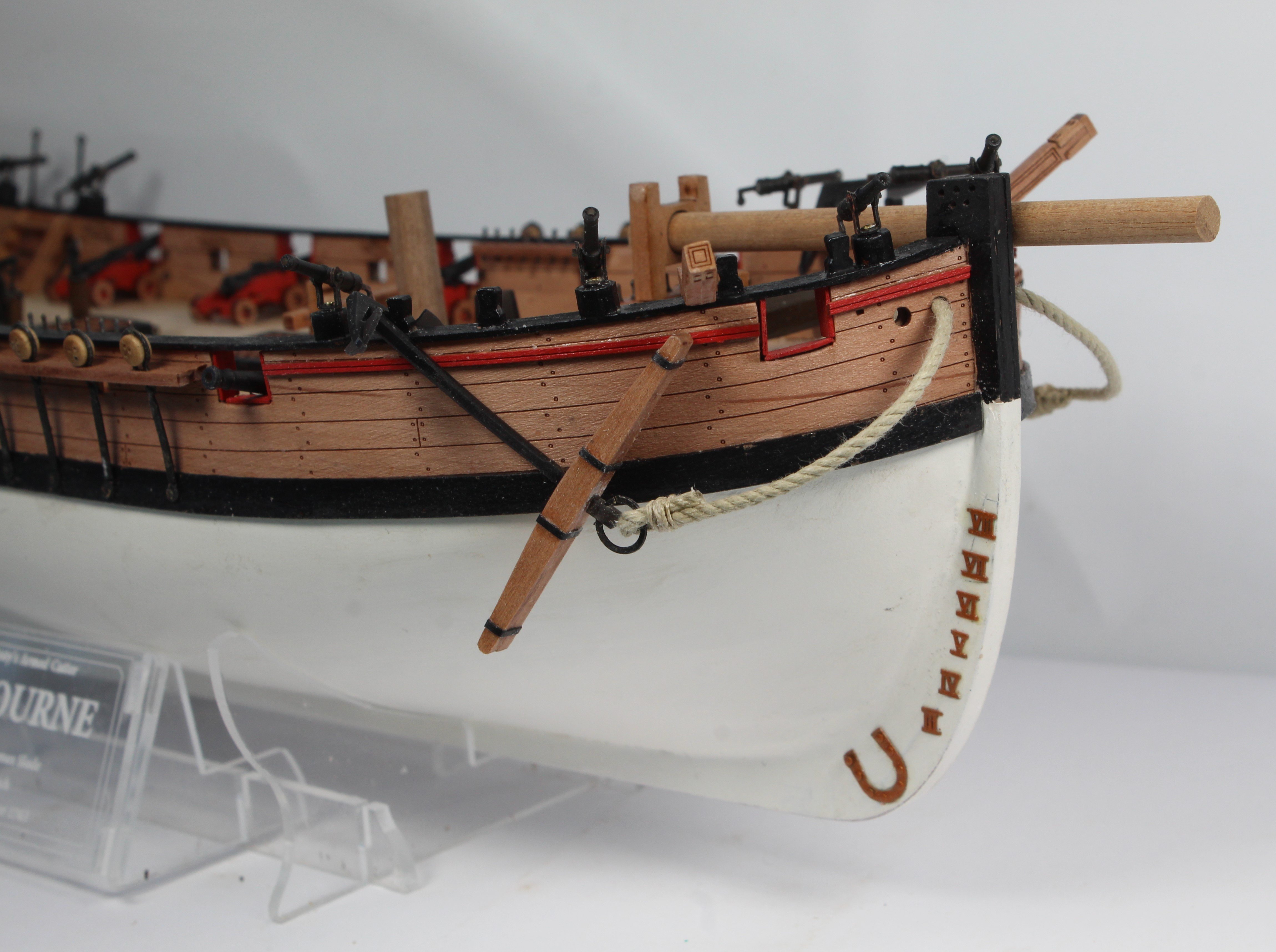
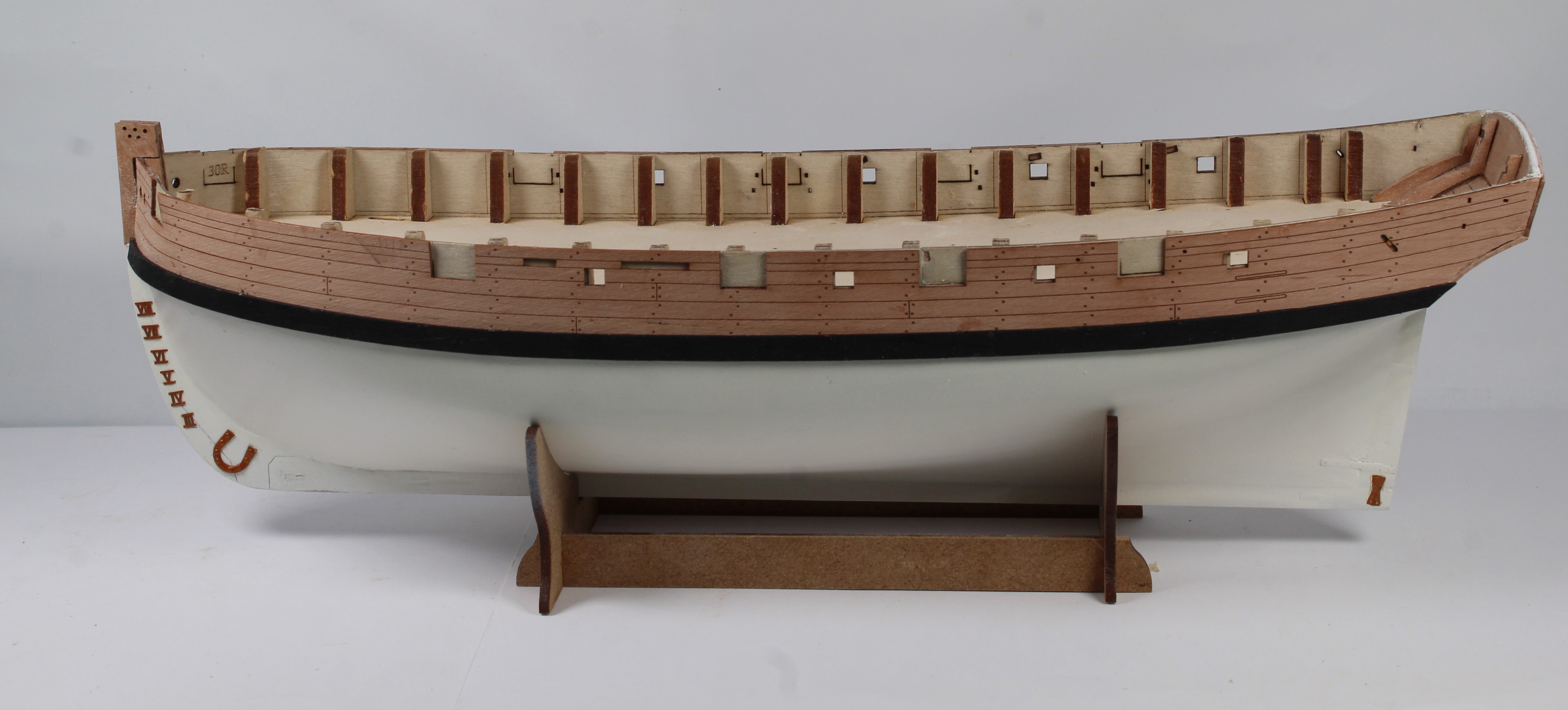
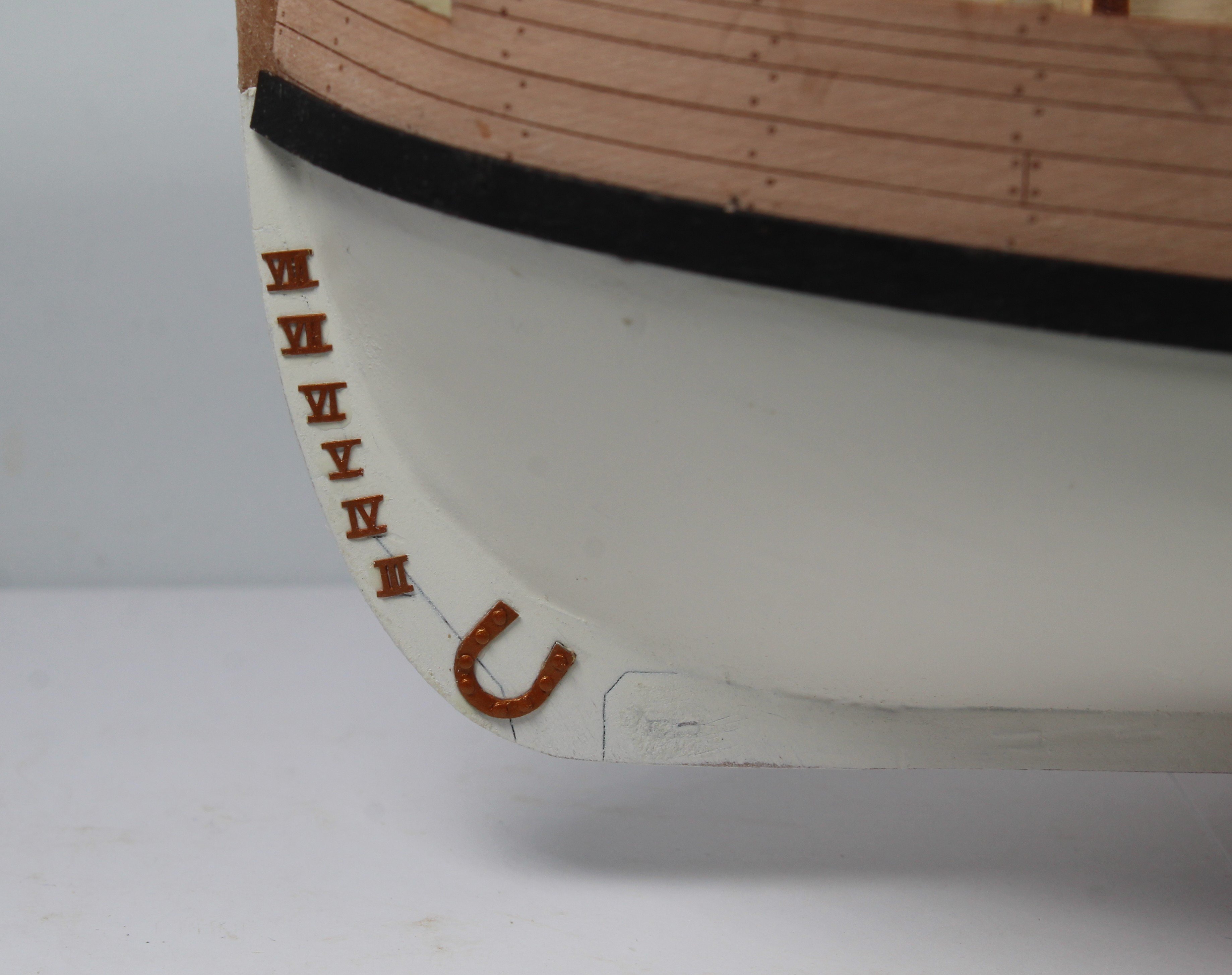
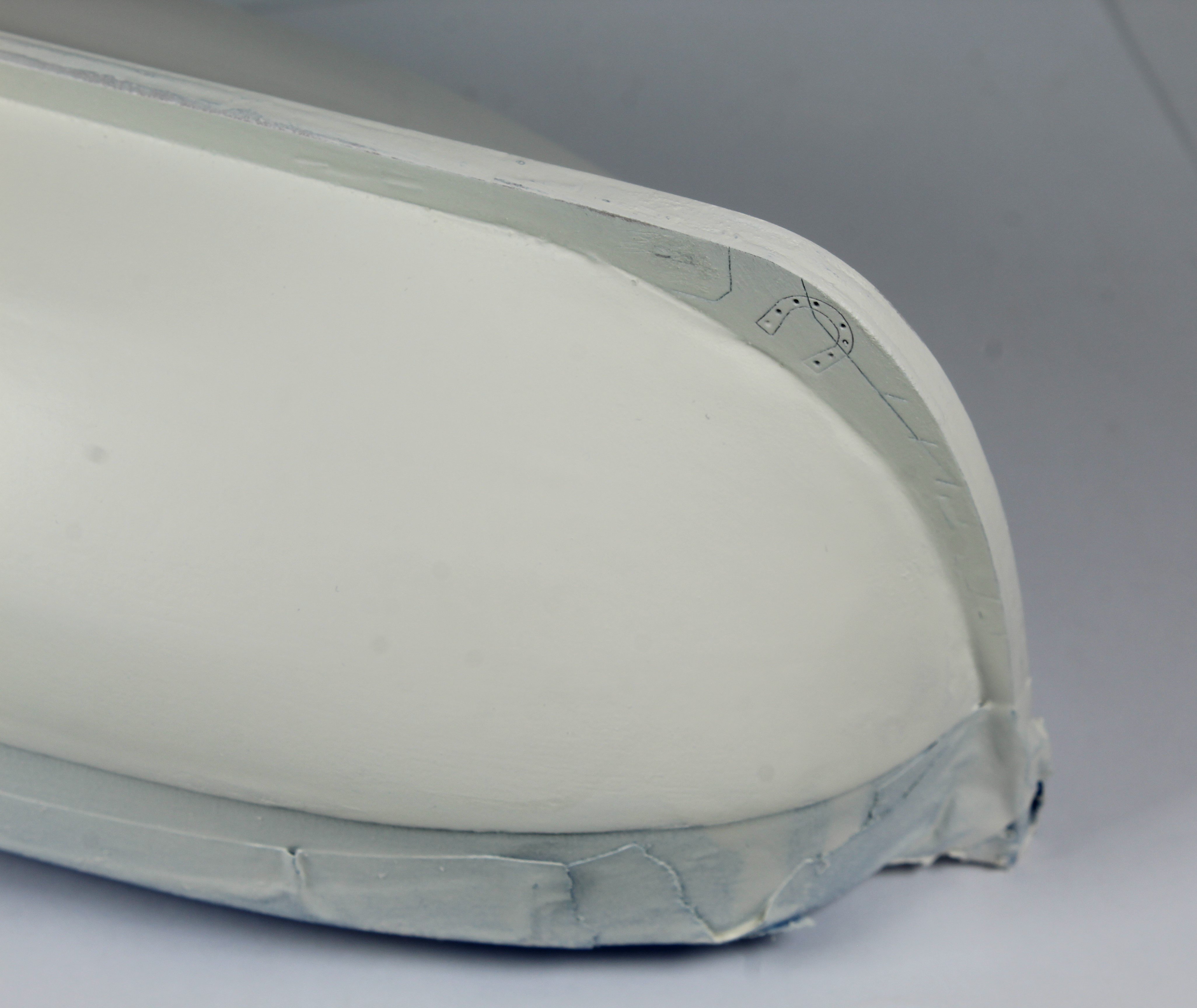
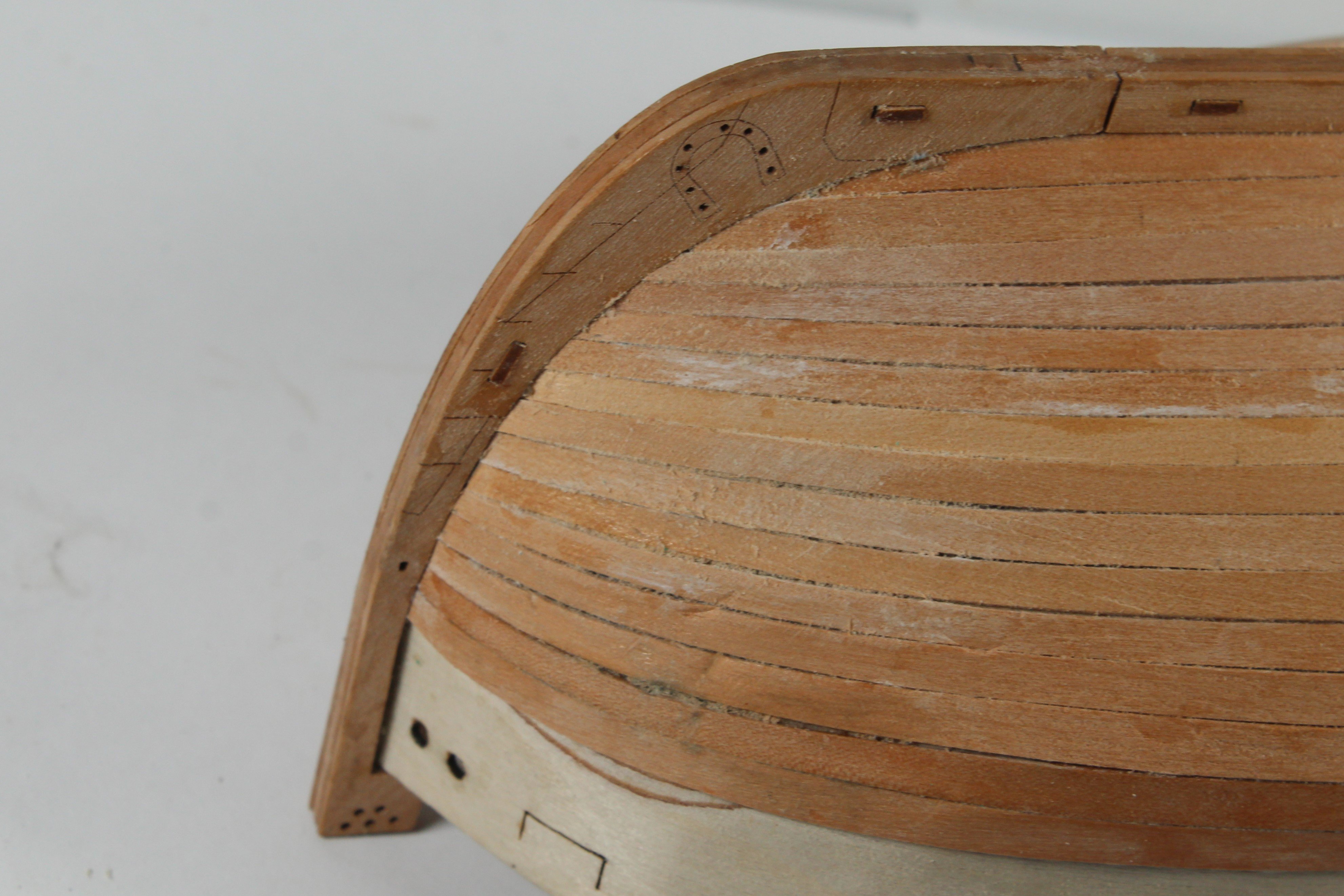
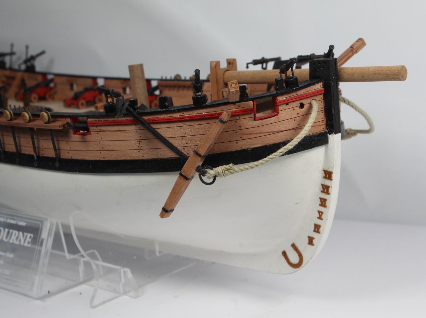
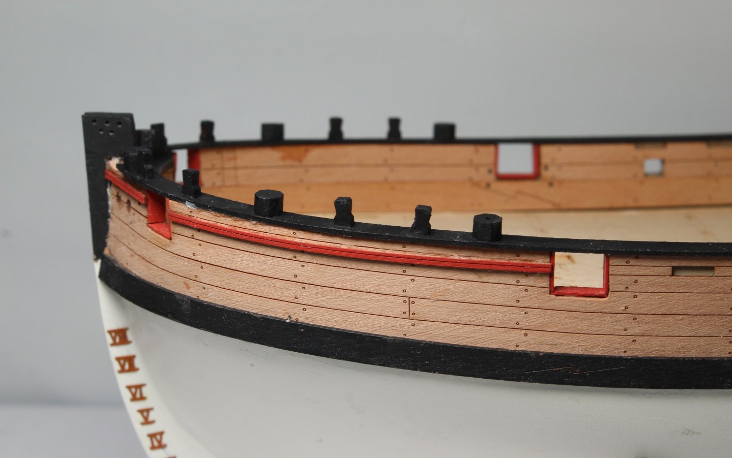
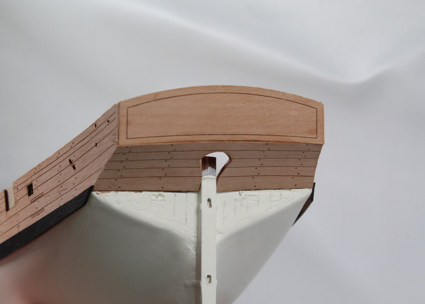
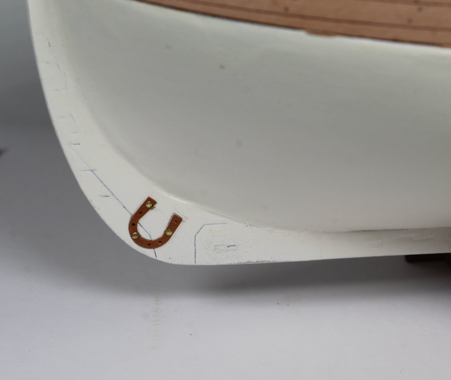
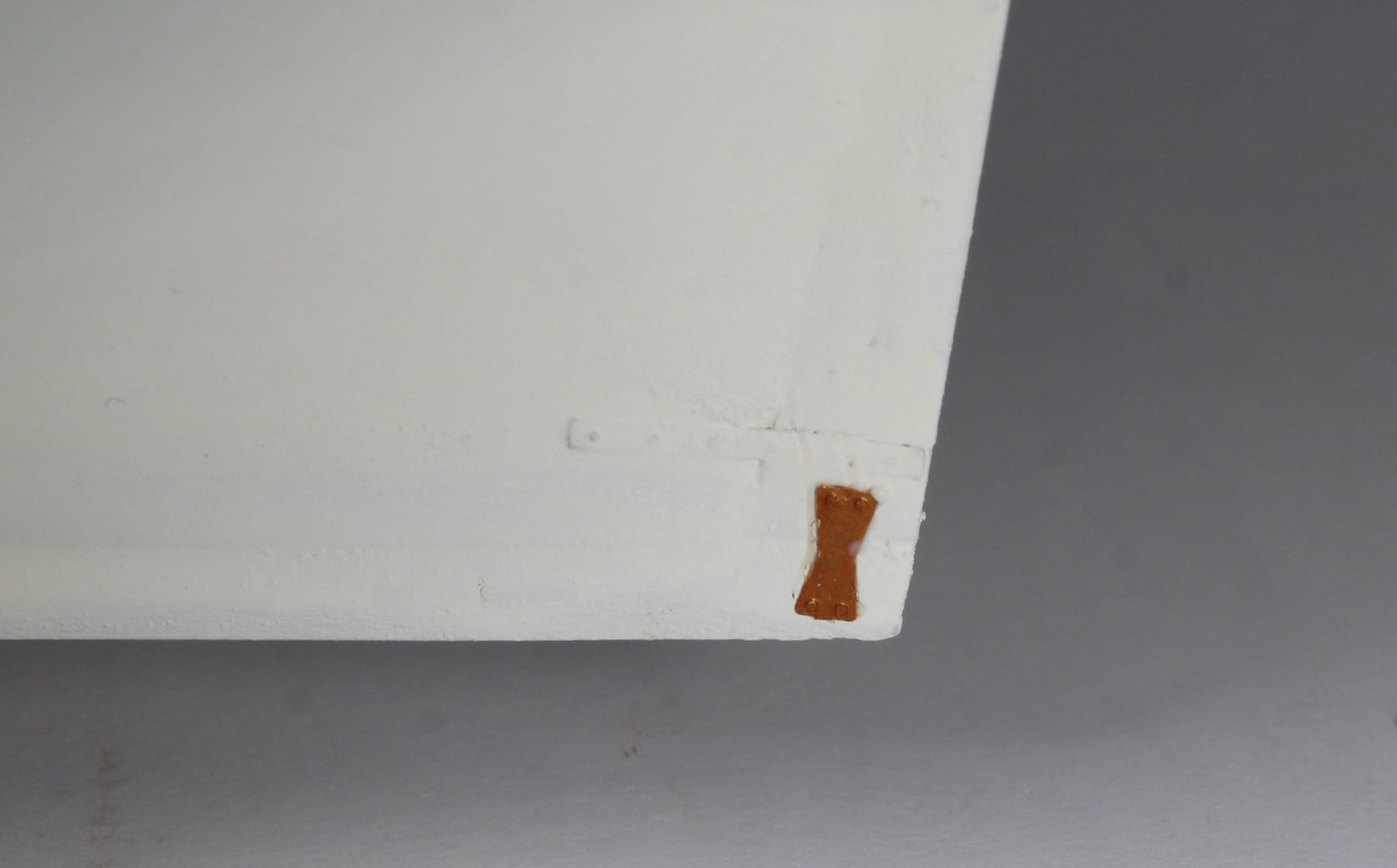
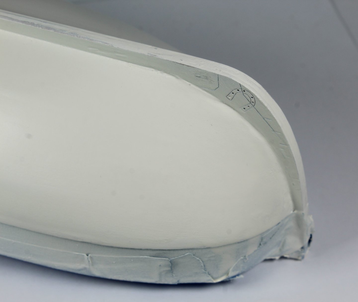
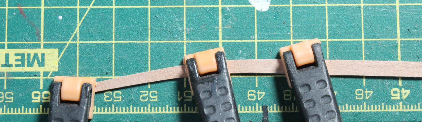
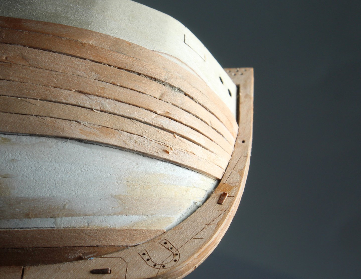
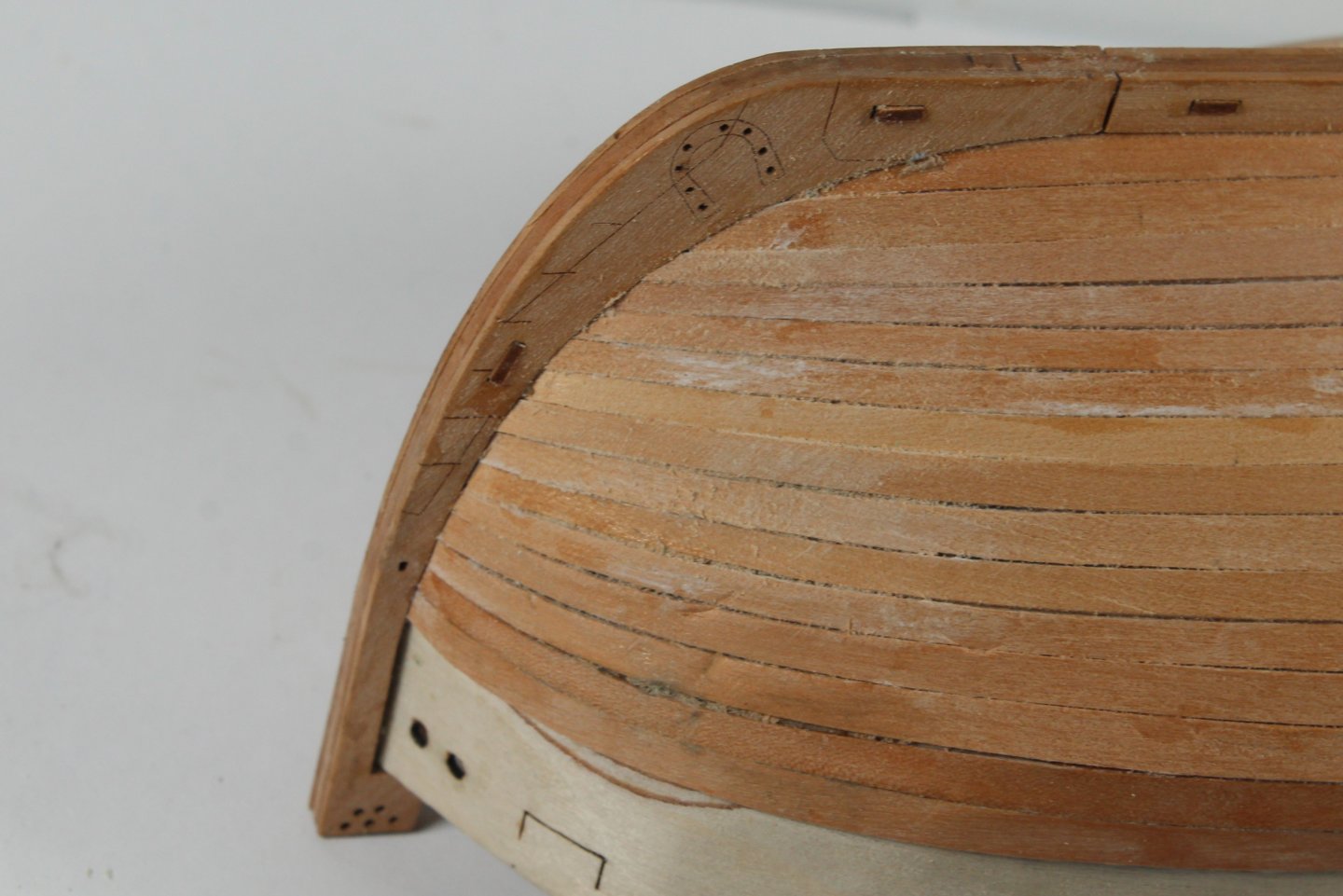
Stage 14 – Wales and Depth Markings Hull Construction – Hull PE Parts Build Steps 51-52 After bending the two wale patterns for a good fit around the bow area they were painted black. I did apply a WOP coat before painting the wales. The wales were they glued and clamped in place. Next I added the horseshoe and depth markings to the hull. Cut down pins were inserted in all of the horseshoe holes. I have now completed the basic hull assembly phase of this build. Time Taken 120 mins As can be seen in the photo below I need to tidy up the lower stern panel paint job.


- 43 replies
-
- 5
-
-
- Vanguard Models
- Sherbourne
- (and 1 more)
-
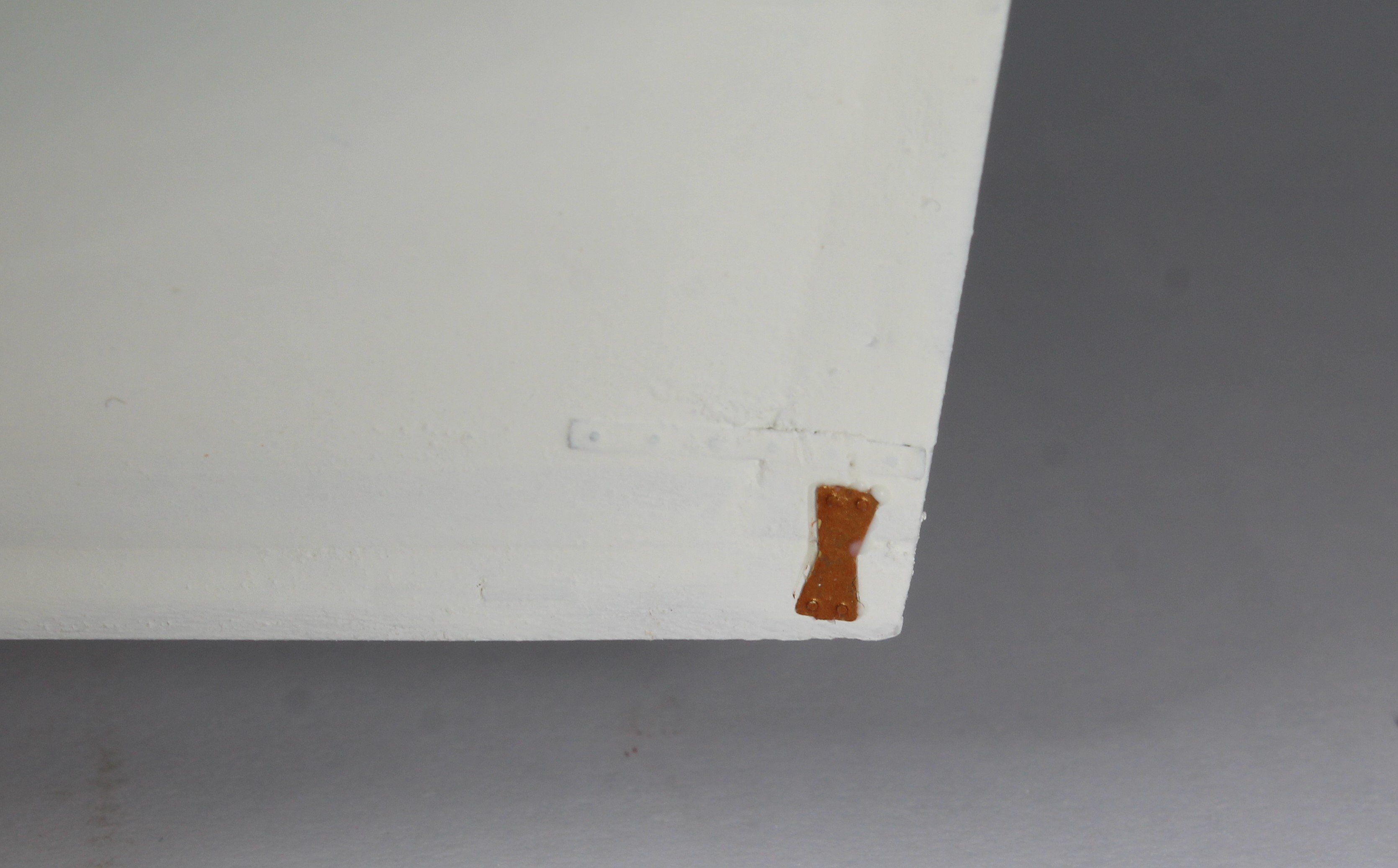
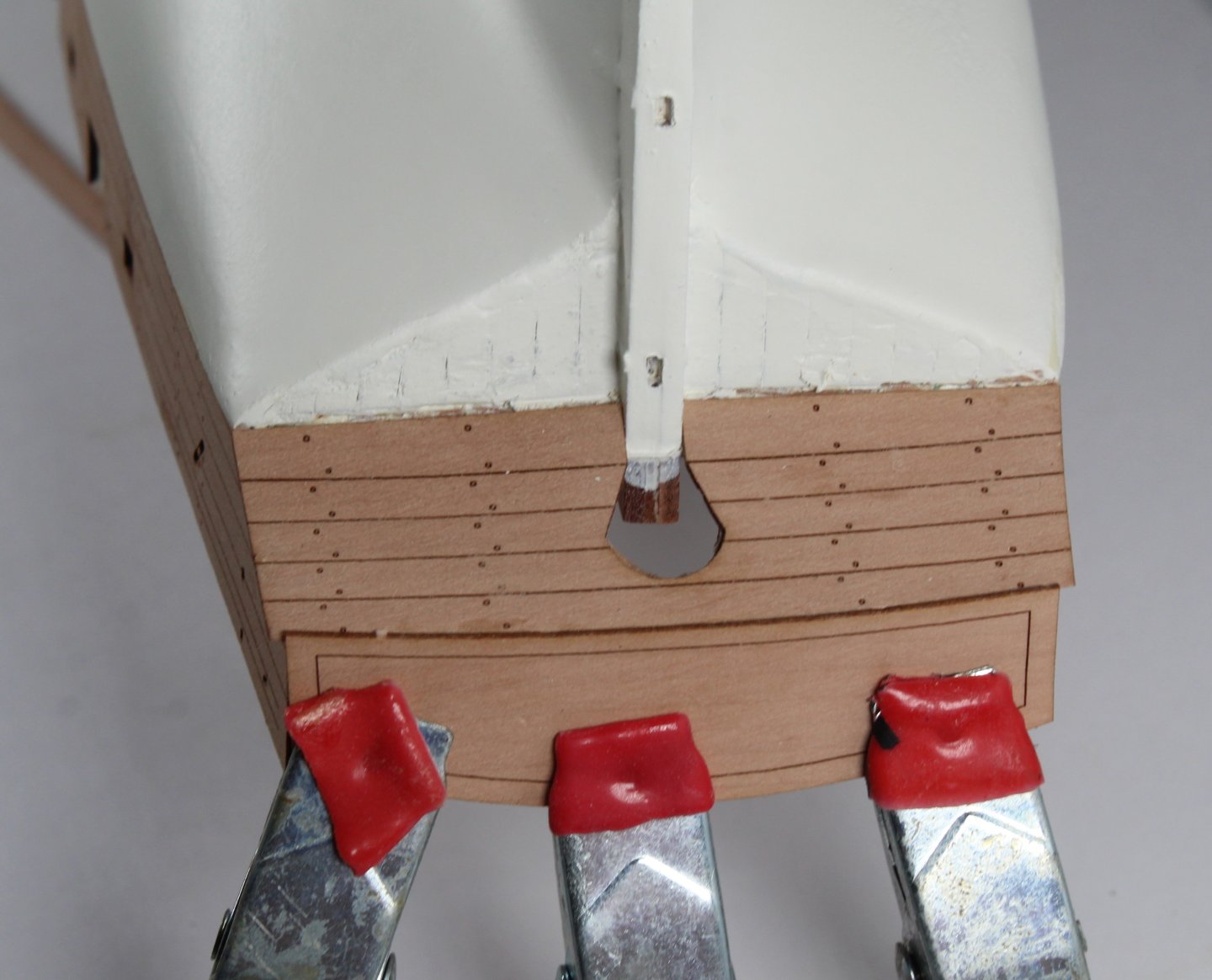
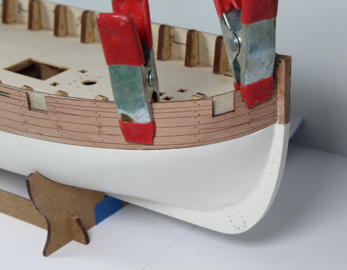
Stage 10 – Outer Bulwark Patterns Hull Construction – Fitting The Outer Bulwark Patterns Build Steps 47 - 48 After test fitting the previously shaped patterns the two outer bulwark patterns were added to the hull assembly. I brushed plenty of wood glue to the hull and the two patterns were then carefully positioned and clamped the hull, as can be seen in the following two photos. Time Taken 10 mins Stage 11 – Shaping the Main Wales Hull Construction – Shaping The Wales Build Steps 51 After wetting the bow end of the two wale patterns they were clamped to the hull and a hair dryer was used help the wale retain the bend around the bow. This is shown in the next two photos. The wale patterns will be removed and painted black before they are glued in place. I have also sanded the excess material shown by blue arrow in second photo from the stern area. Time Taken 10 mins Stage 12 – Fitting Lower Stern Counter Pattern Hull Construction – Outer Lower Stern Counter Pattern Build Steps 49 After wetting the outer lower stern counter pattern it was clamped to the hull so it could follow the curve. Before gluing the pattern in place, I did a test fit of the transom rail pattern. Everything looks good so the lower stern counter pattern was glued in place. Time Taken 20 mins Stage 13 – Horseshoe Show and Fishplates Hull Construction – Hull PE Parts Build Steps 52 A coating of photo etch primer paint was sprayed on the PE parts for the horseshoe, fishplates and depth markings. They were then painted copper. As can be seen in the the next two photo the two horseshoe patterns have been test fitted and the two fishplate patterns have been glued in place. Time Taken 10 mins


- 43 replies
-
- 5
-
-
- Vanguard Models
- Sherbourne
- (and 1 more)
-
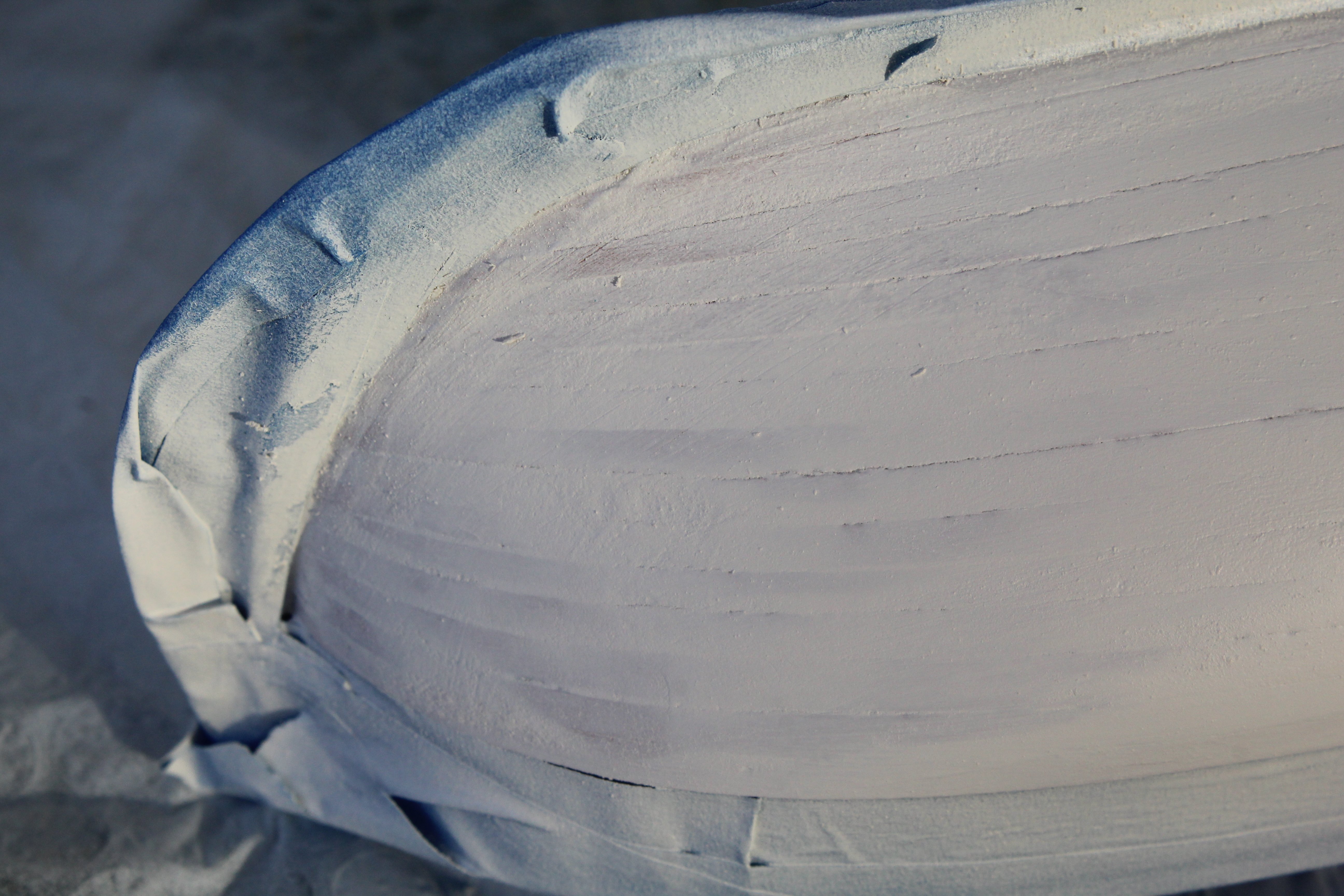
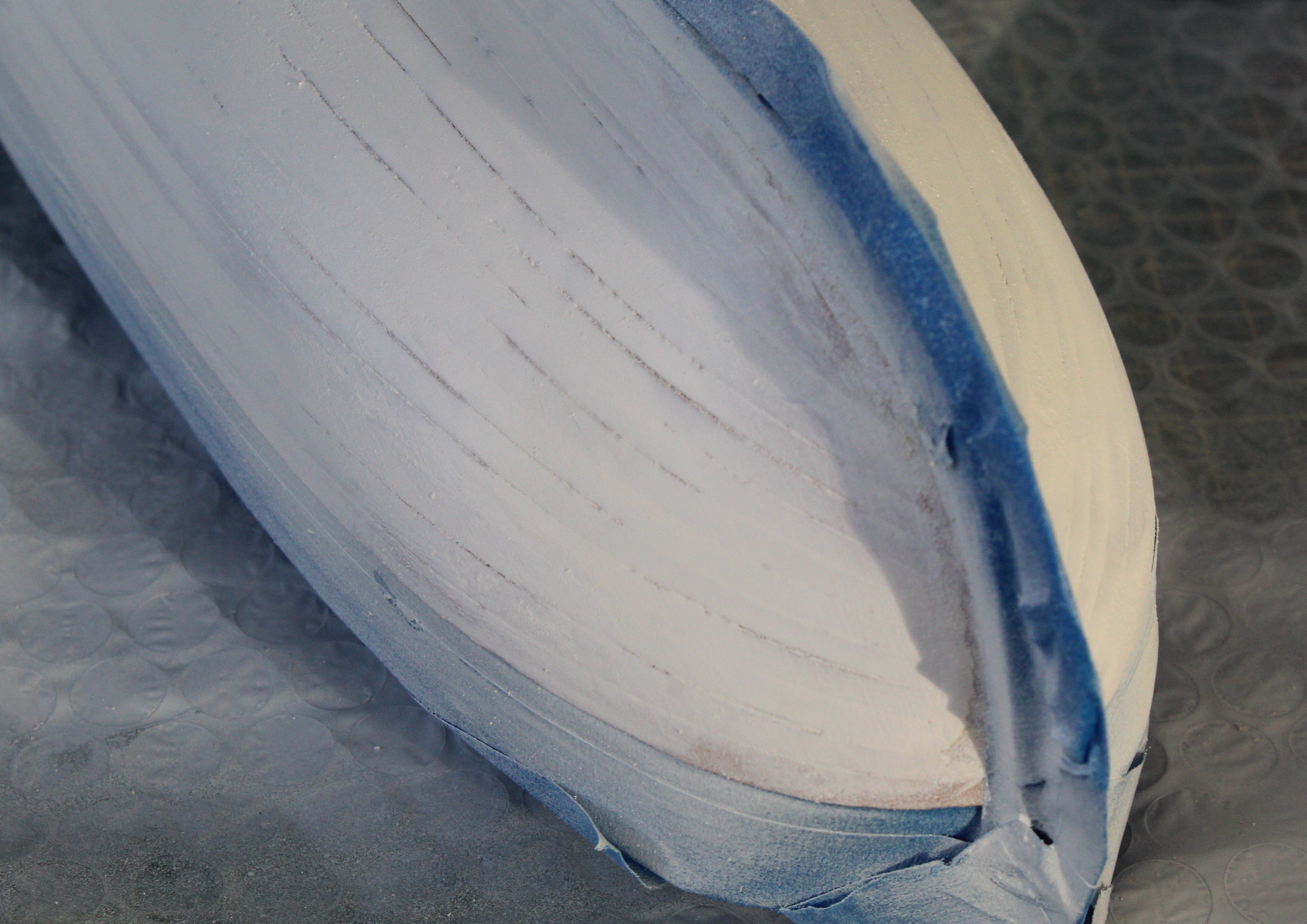
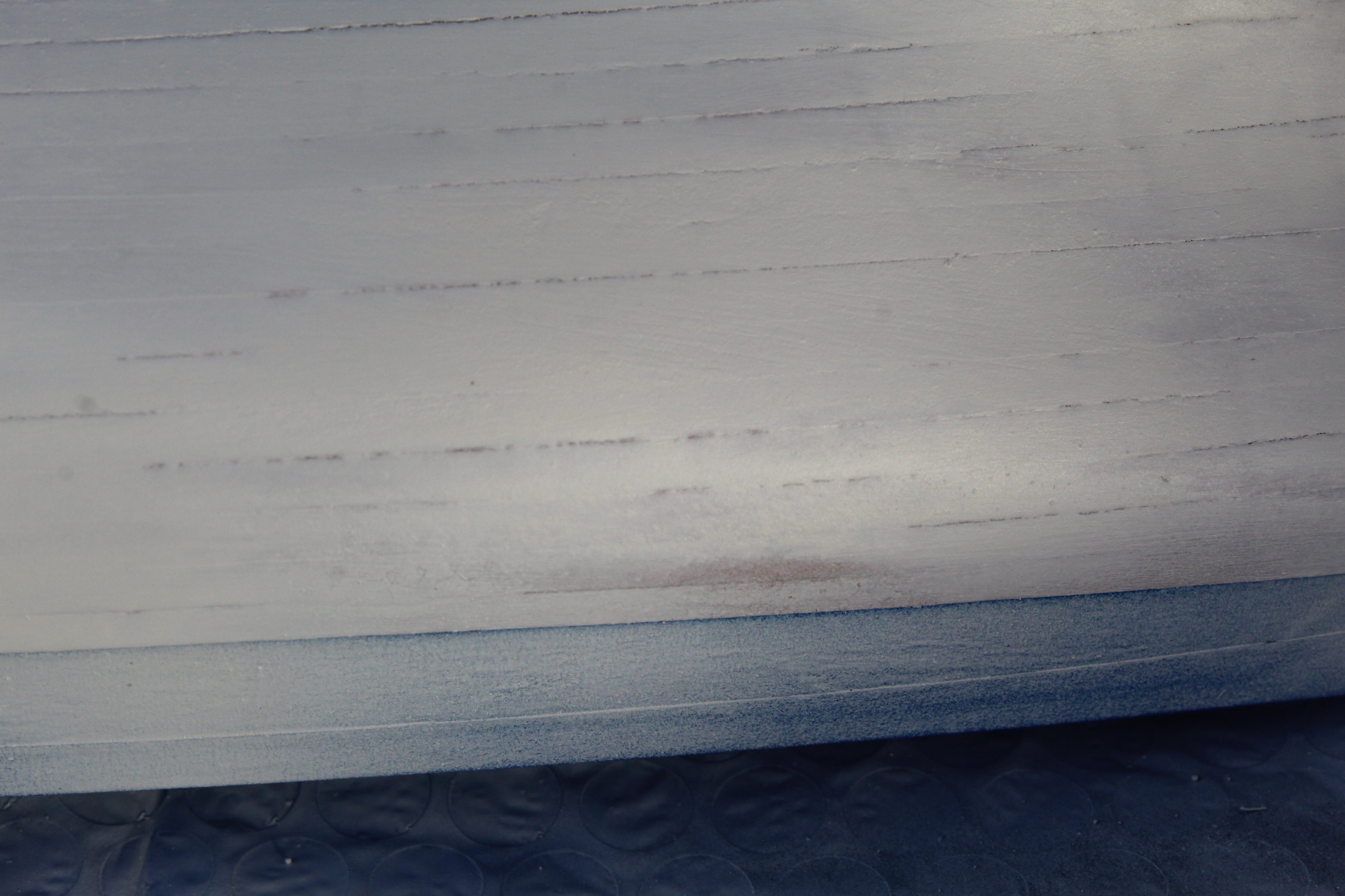
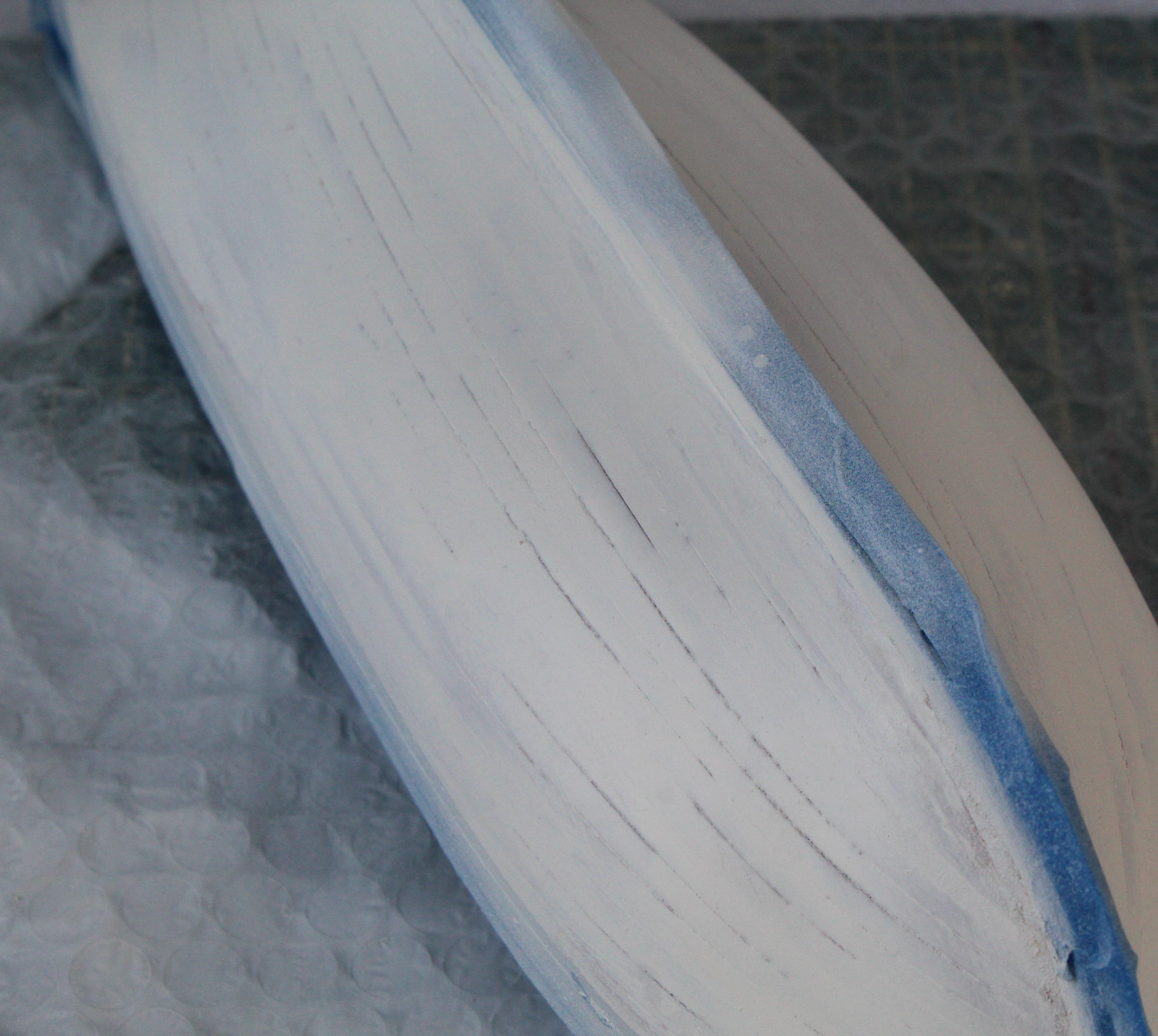
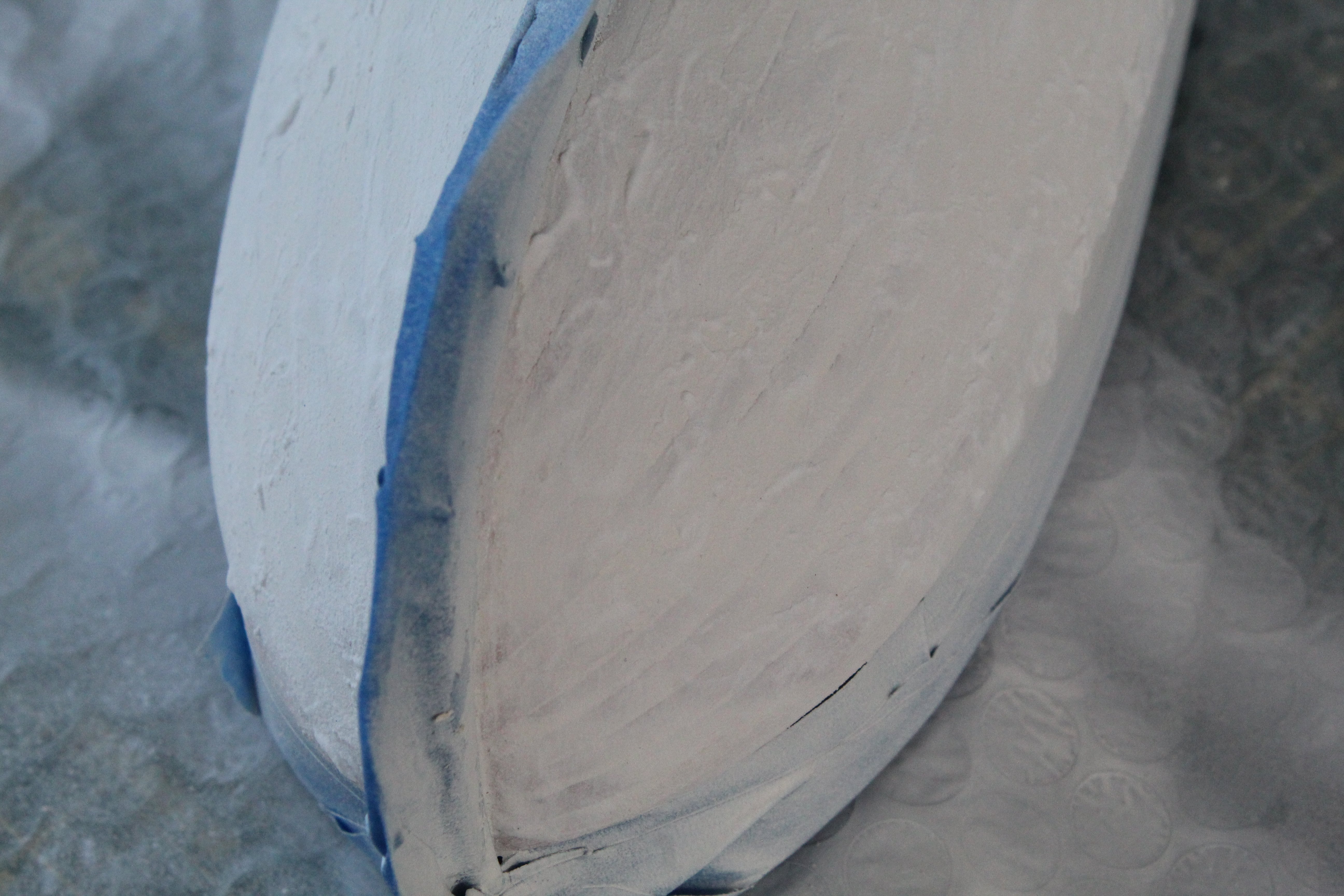
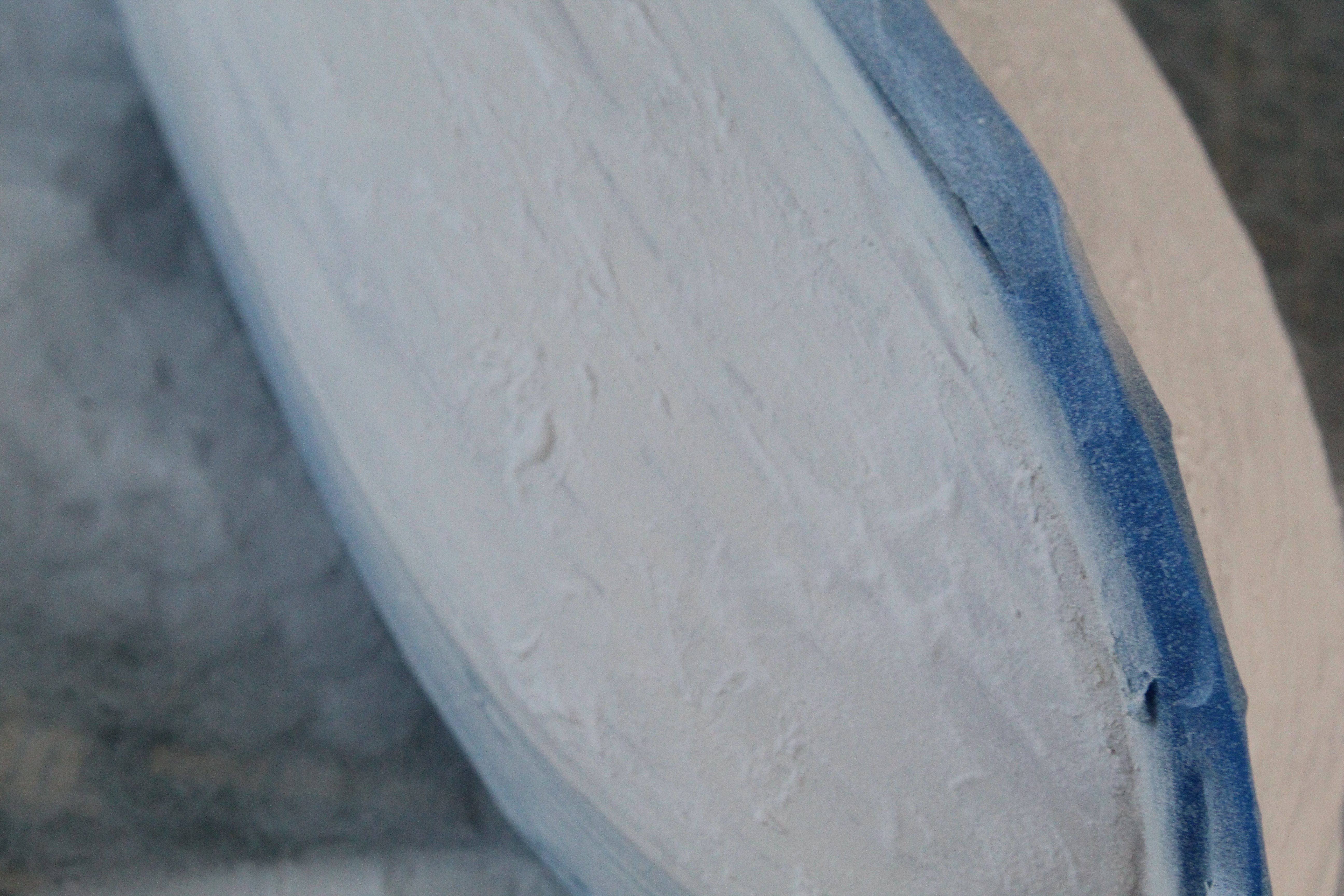
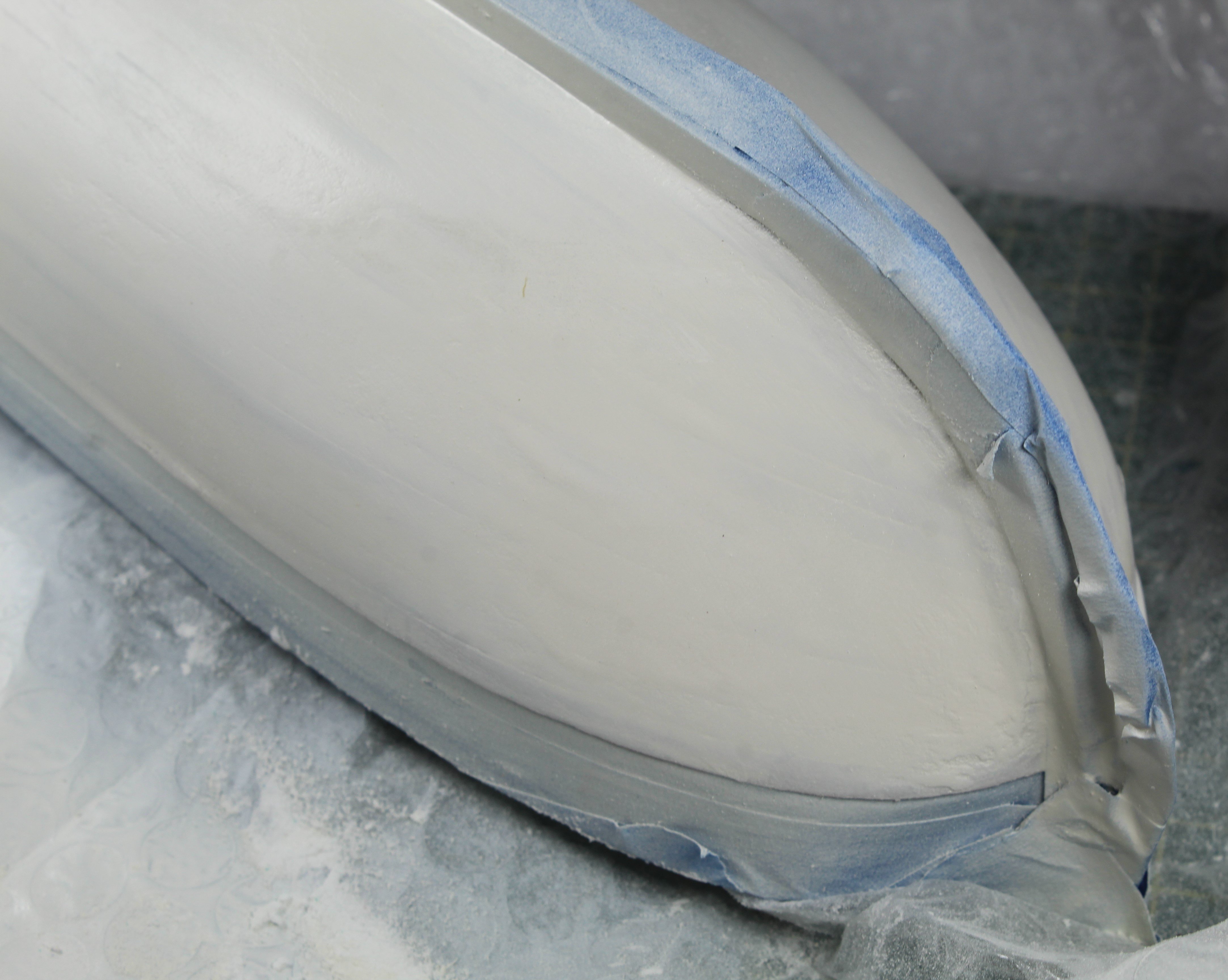
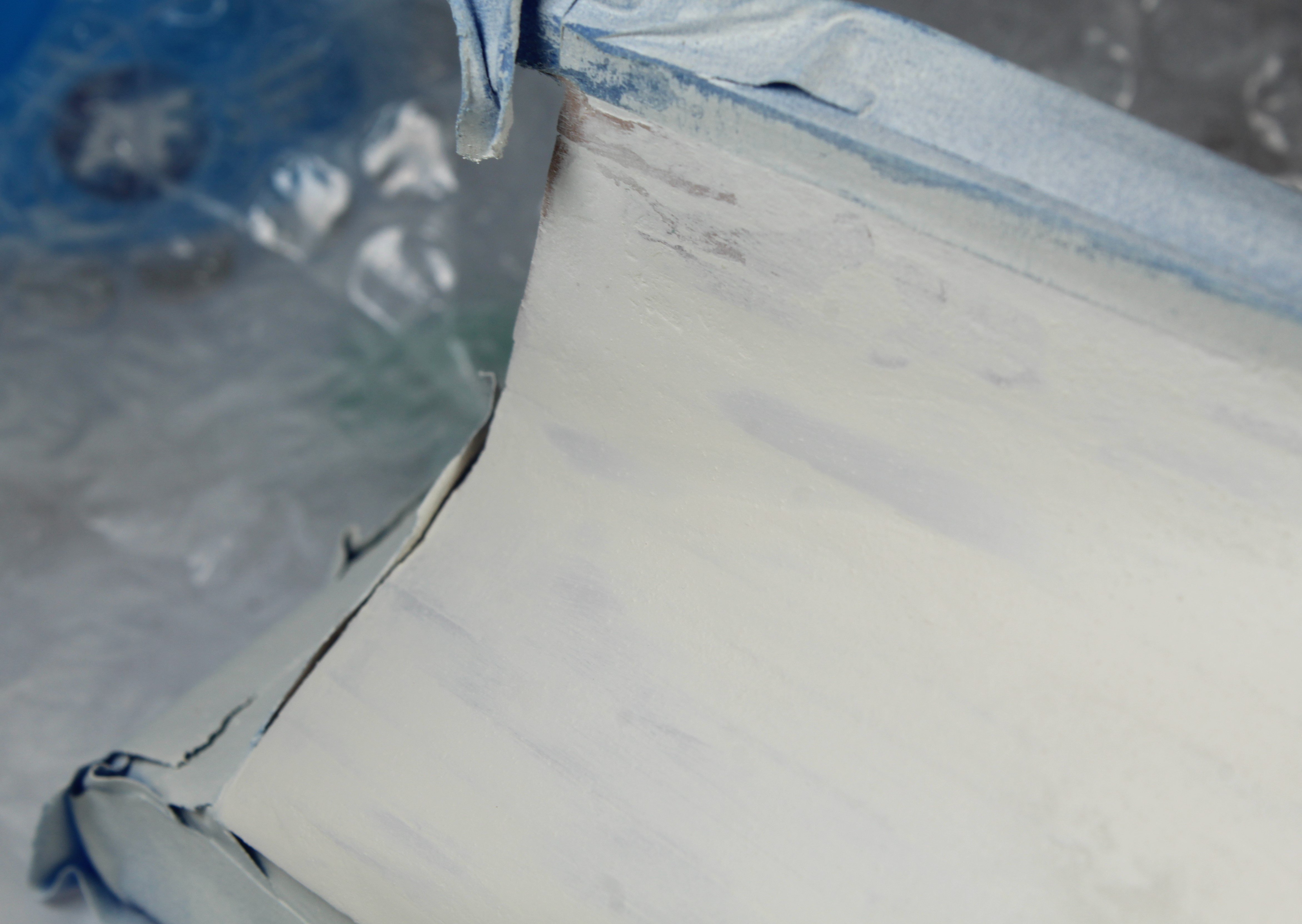
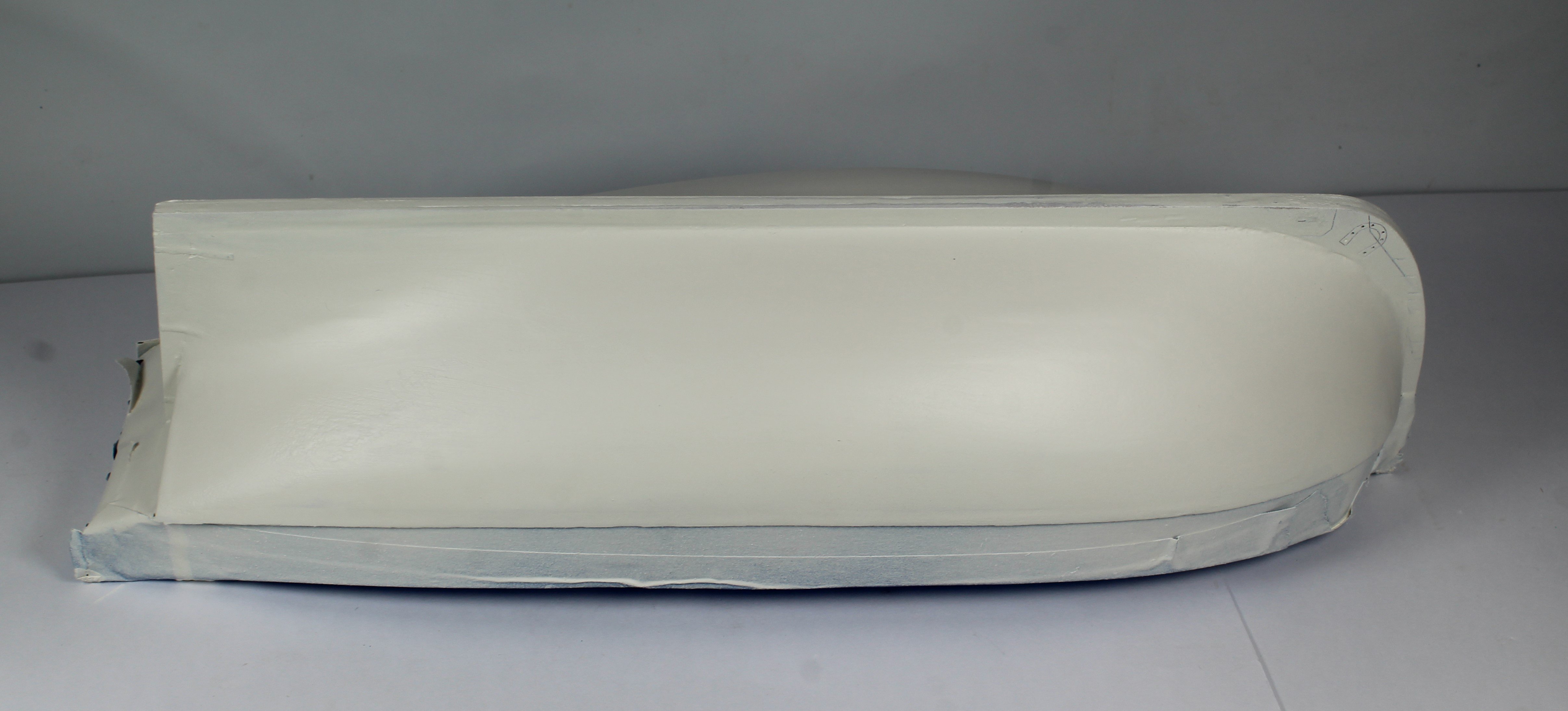
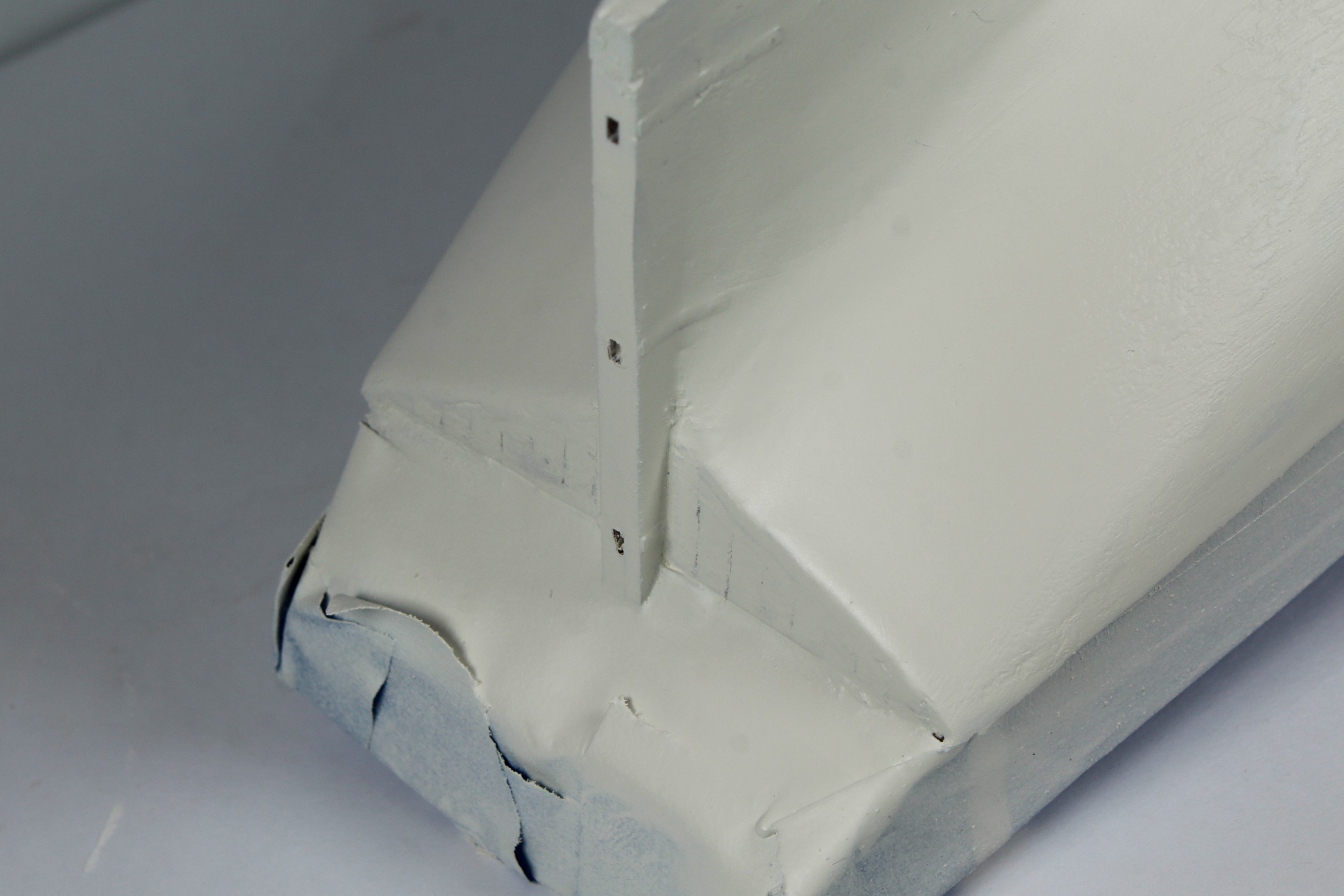
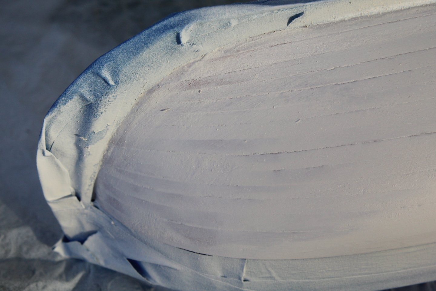
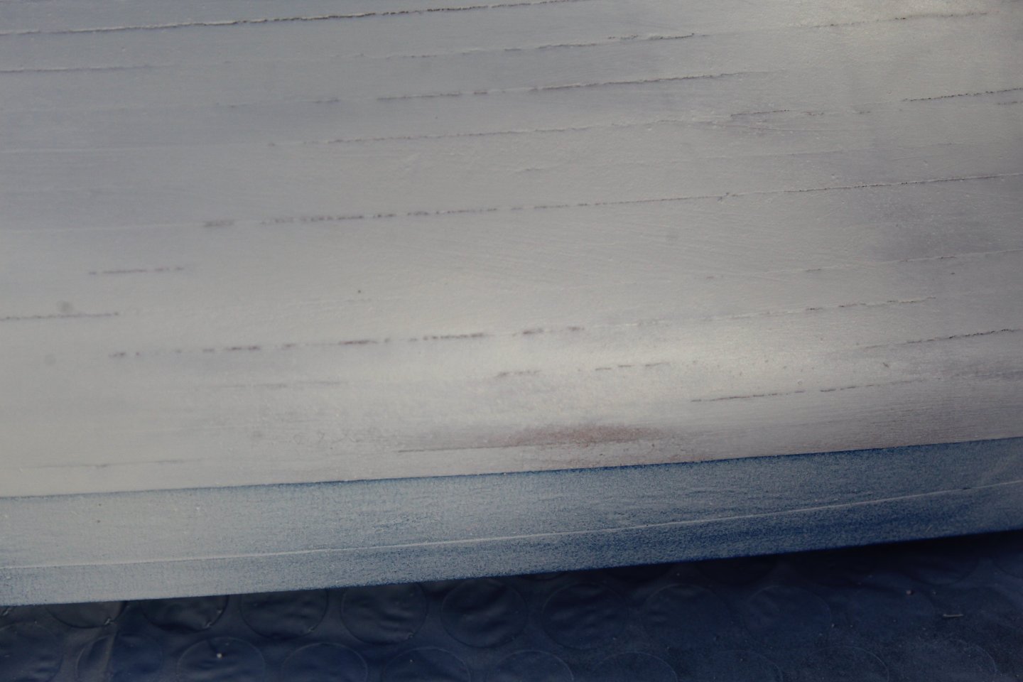
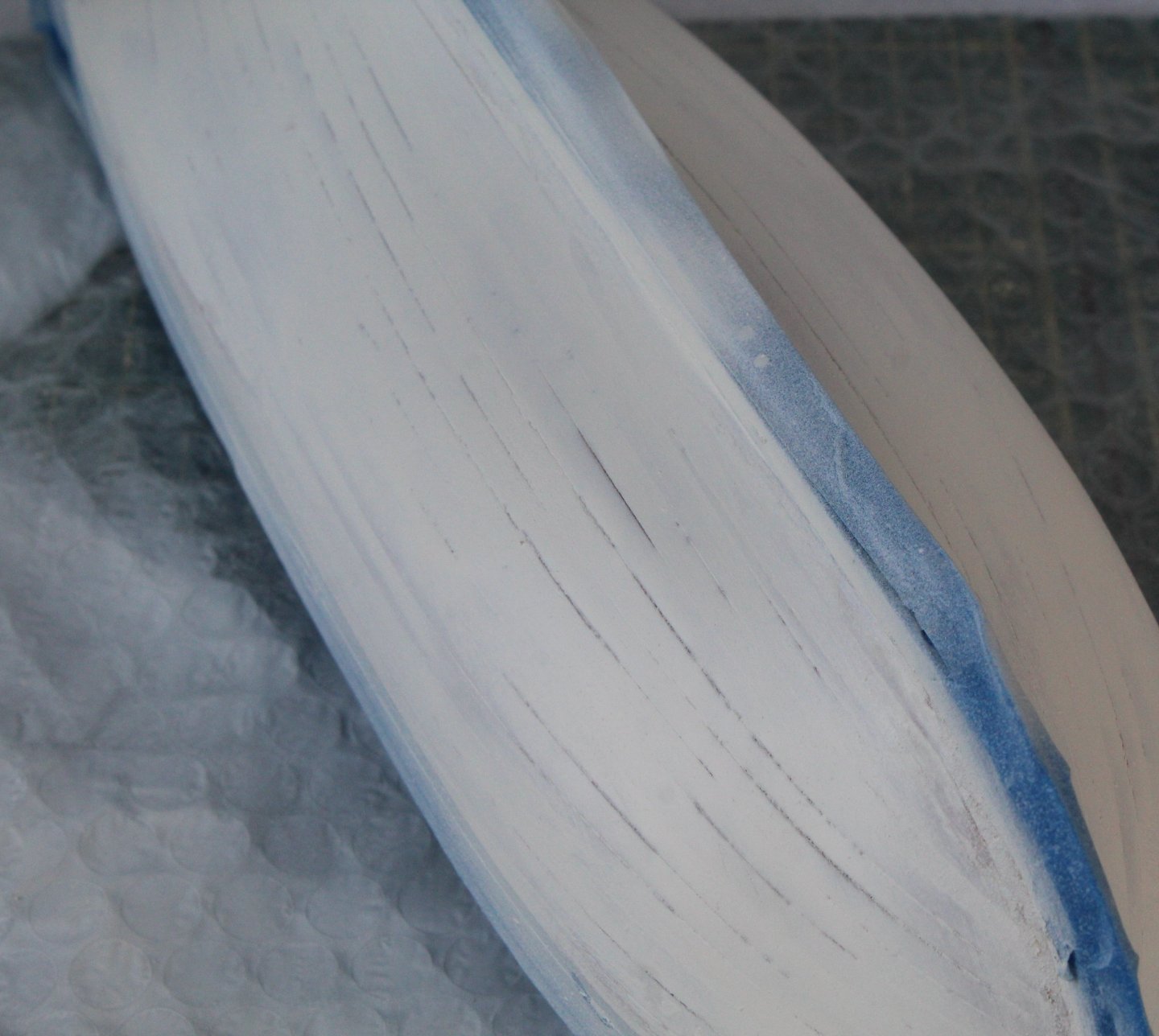
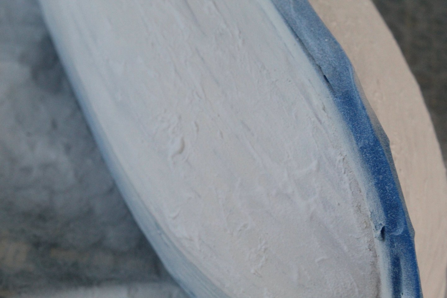
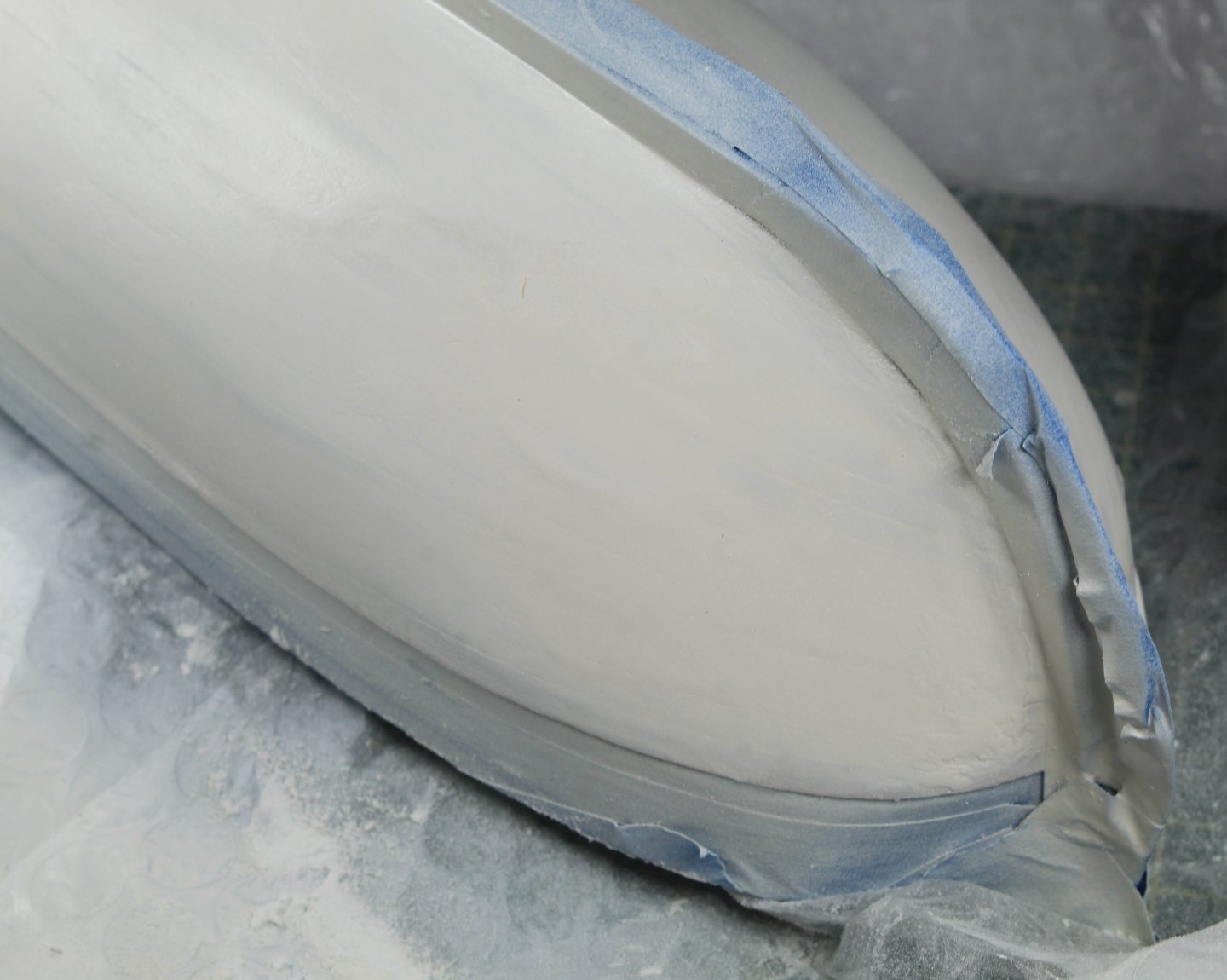
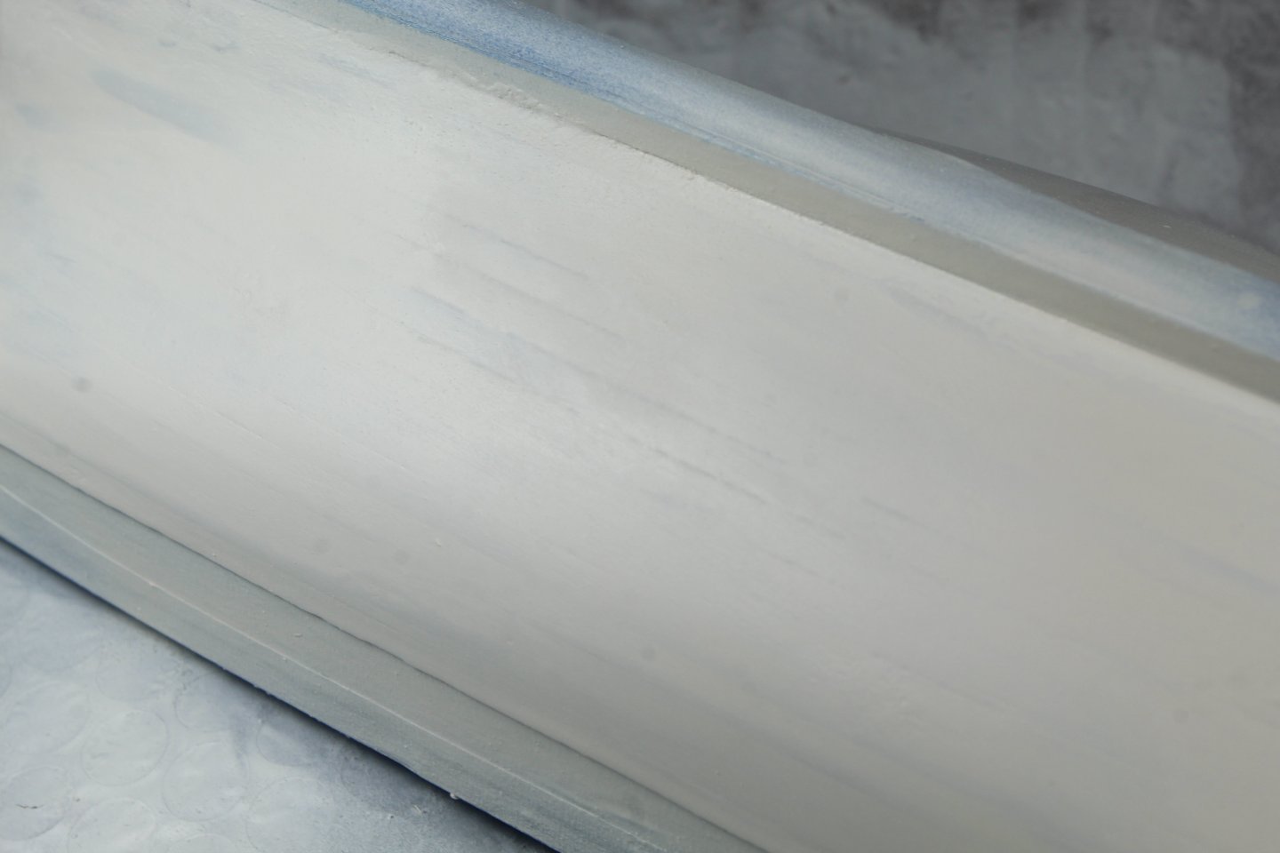
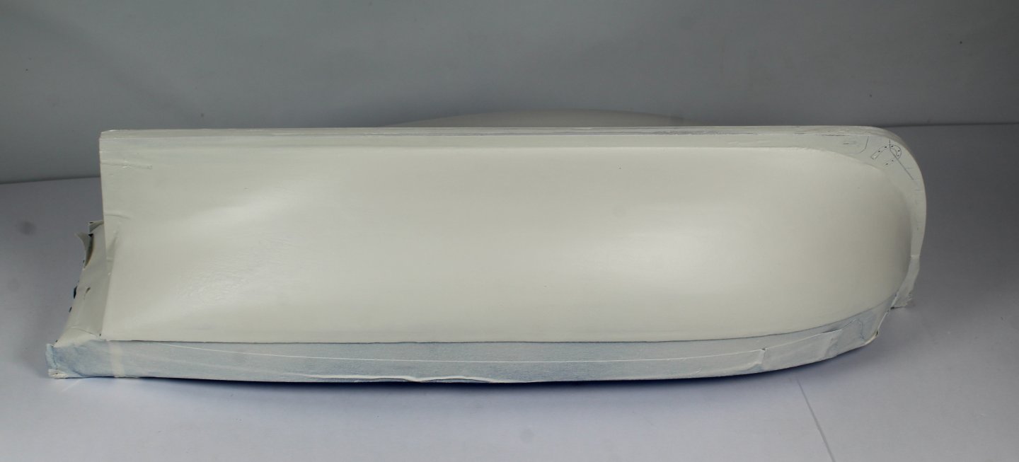
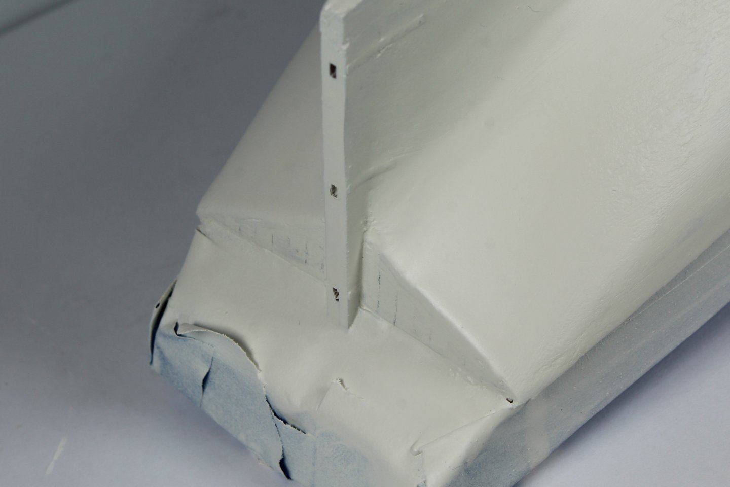
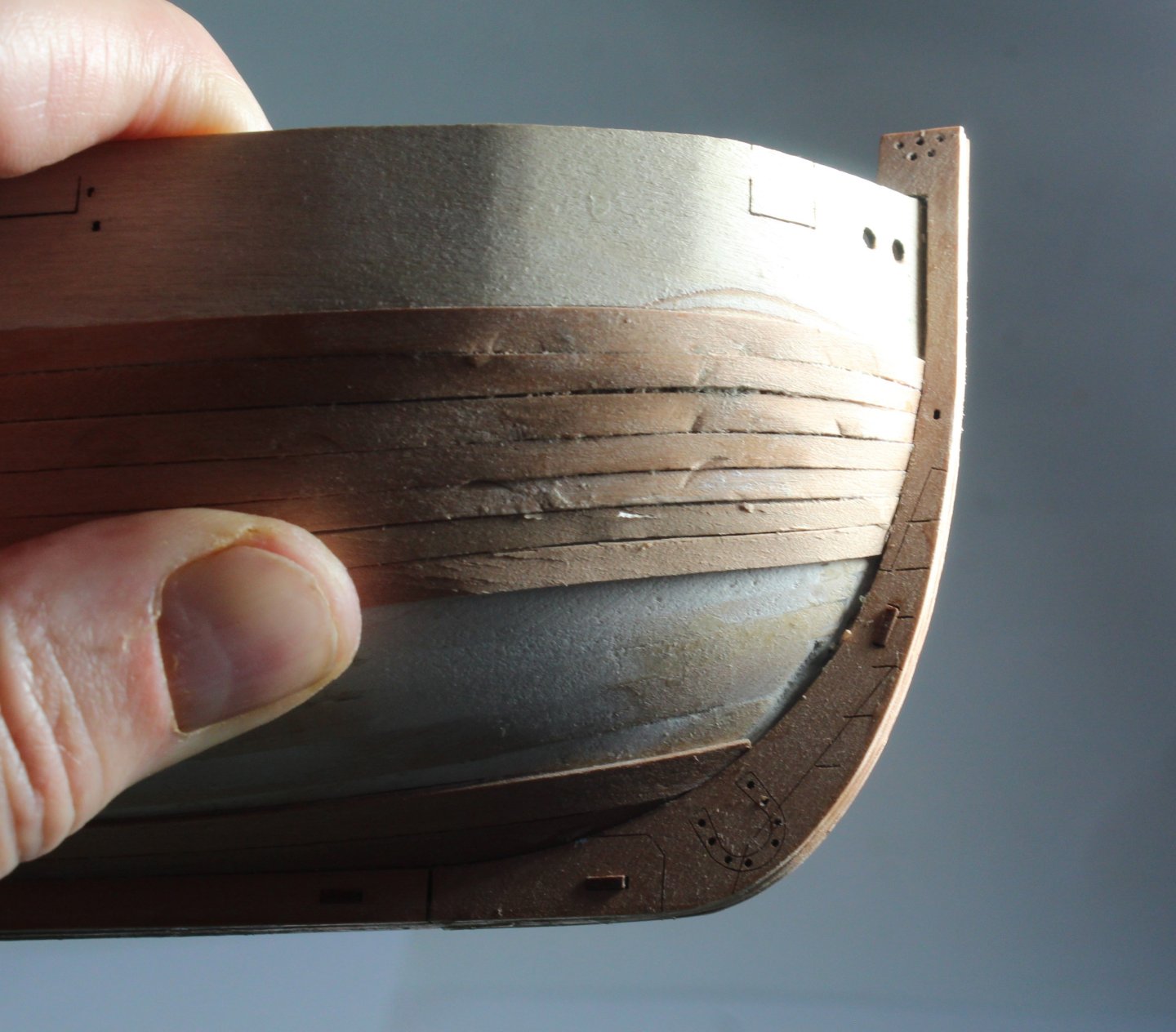
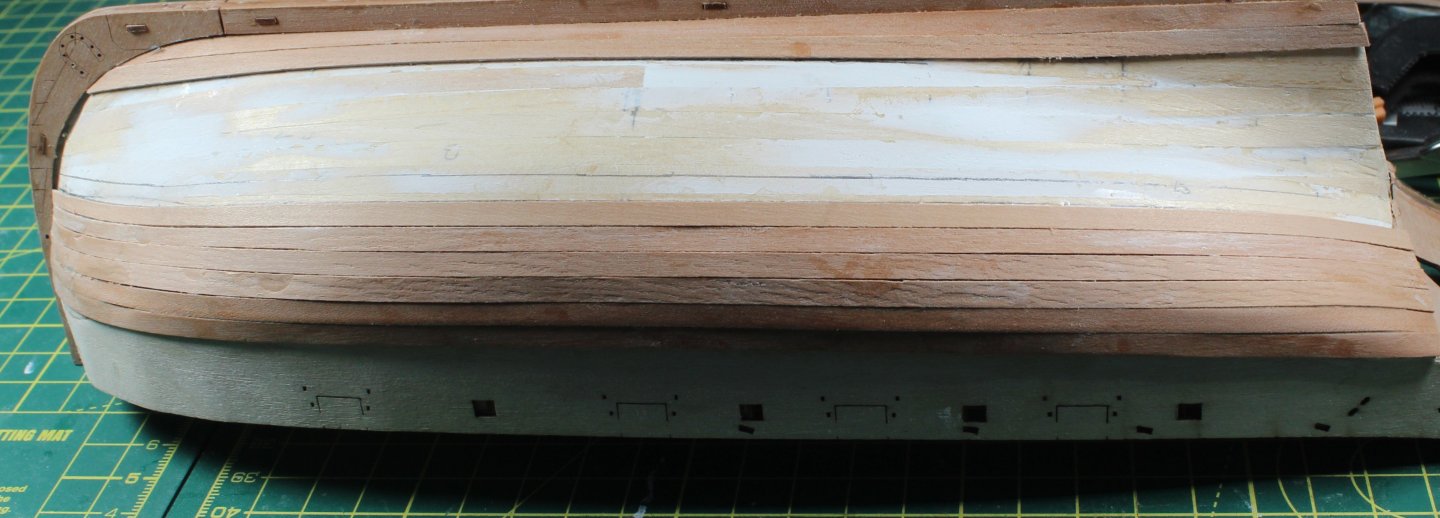
Stage 9 – Pianting The Hull Hull Construction – Painting The Hull – Stage 1 Build Steps 44-46 Painting the hull white takes time to get a nice even finish. After brushing diluted wood filler in the visible gaps / depressions in the completed second planking the hull is sanded until it feels smooth to touch. A thin coat of white paint was then applied to the hull as this really shows up the defects as can be seen in the following four photos. Time Taken 30 mins Hull Construction – Painting The Hull – Stage 2 Build Steps 44-46 A liberal amount of slightly diluted wood filler to the hull, as can be seen in the next two photos. Time Taken 10 mins Hull Construction – Painting The Hull – Stage 3 Build Steps 44-46 Once the wood filler has dried the hull is once again sanded smooth. As can be seen in the next three photos the hull is looking smoother, but more work is still required. Time Taken 20 mins Hull Construction – Painting The Hull – Stage 4 Build Steps 44-46 More diluted wood filler is then applied to the areas which need more attention and then the hull is once again sanded smooth and this process is repeated until I was happy the end result, as shown in the next three photos. Time Taken 60 mins Hull Construction – Painting The Hull – Stage 5 Build Steps 44-46 The rudder was also assembled and painted and then test fitted, as shown in the next photo. It will be added to the hull later in the build process. Time Taken 10 mins Hull Construction – Painting The Hull – Stage 6 Build Steps 44-46 The outer bulwark patterns were then test fitted against the painted hull and everything look good. Time Taken 5 mins


- 43 replies
-
- 7
-
-
- Vanguard Models
- Sherbourne
- (and 1 more)
-
Thanks, my Harpy kit is in the shipyard and I am itching to get started but I will continue on with the Sherbourne which I am using to try out some different ideas.
- 332 replies
-
- 2
-
-
- Harpy
- Vanguard Models
- (and 1 more)
-
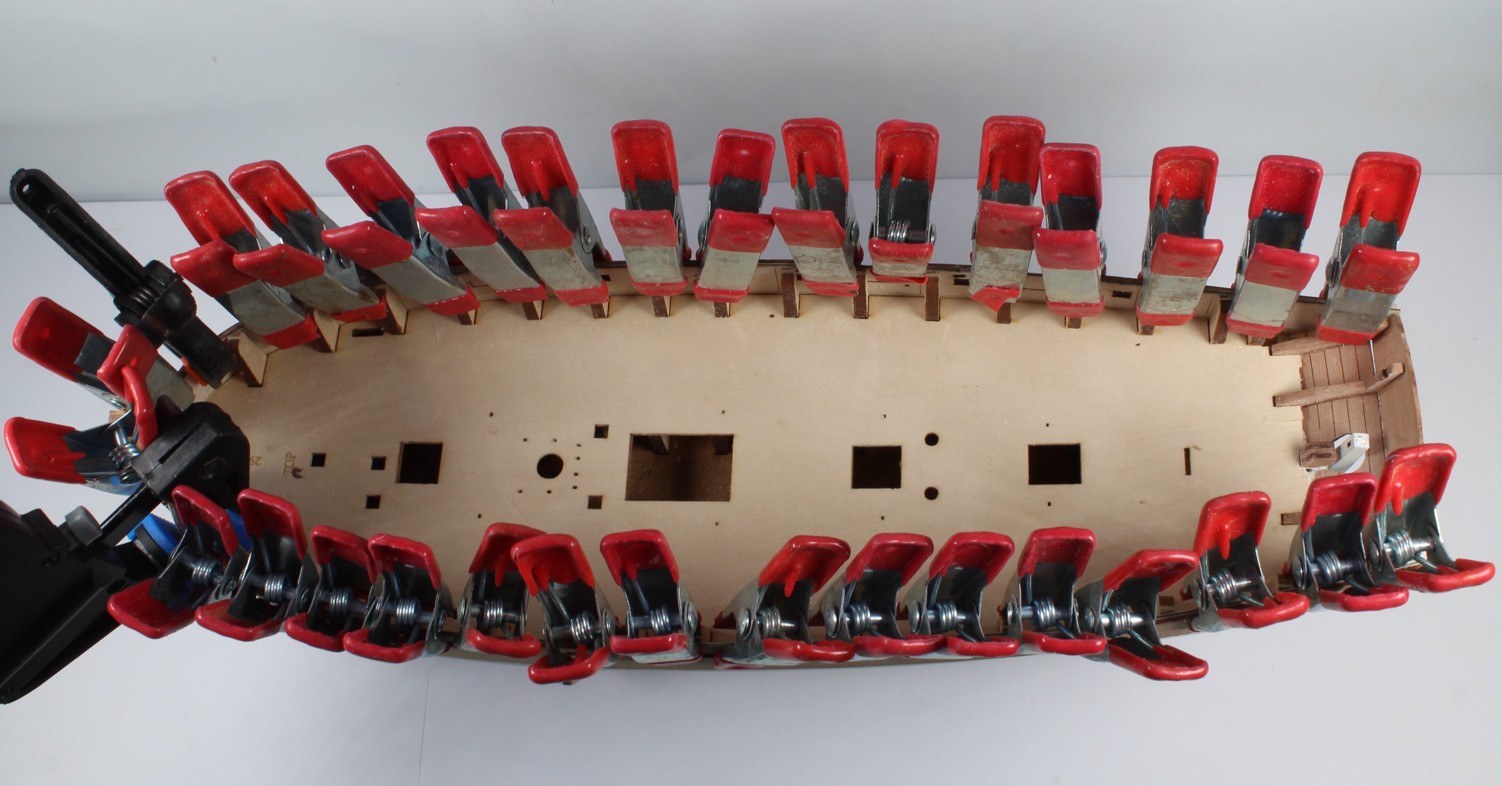
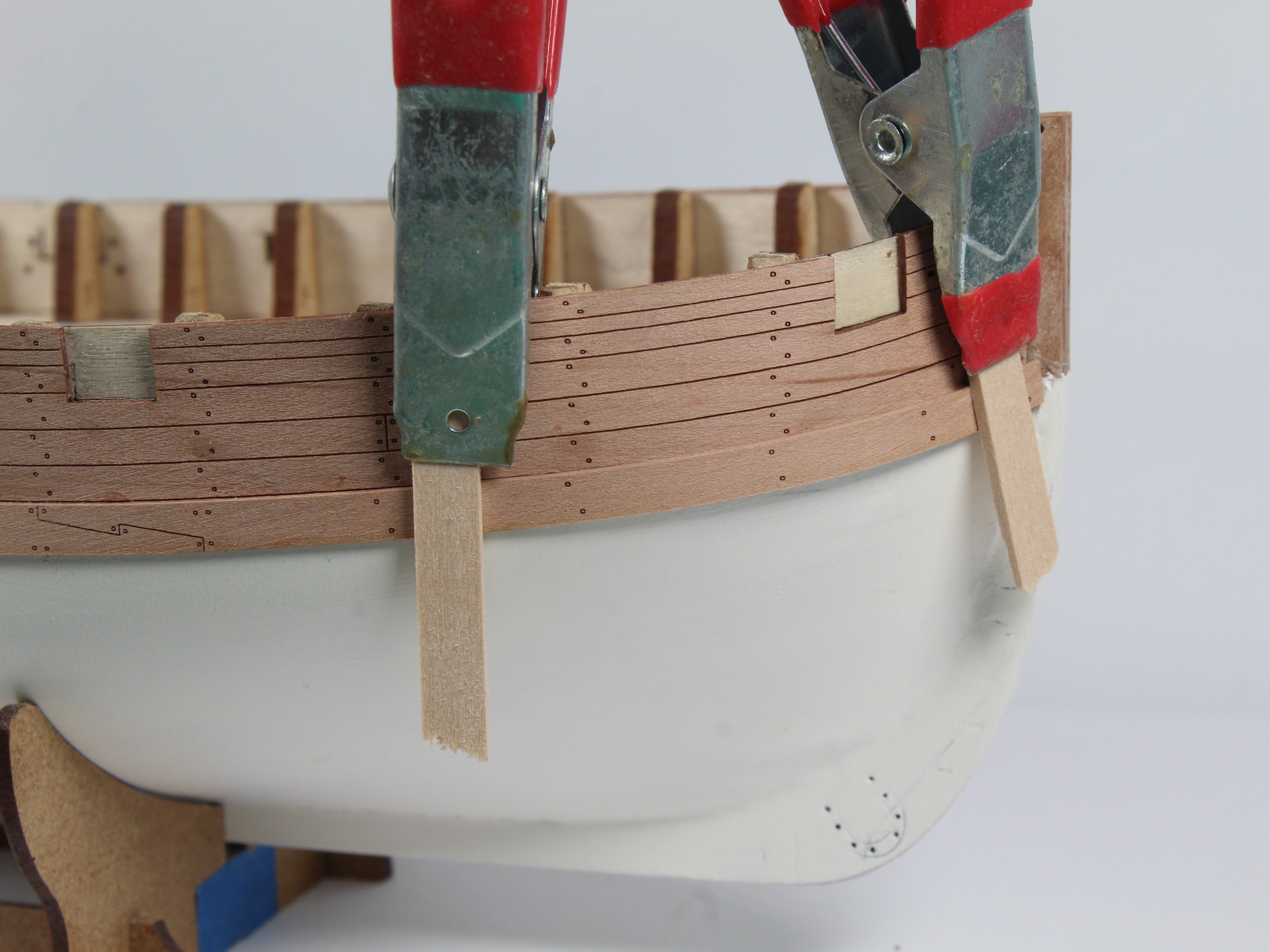
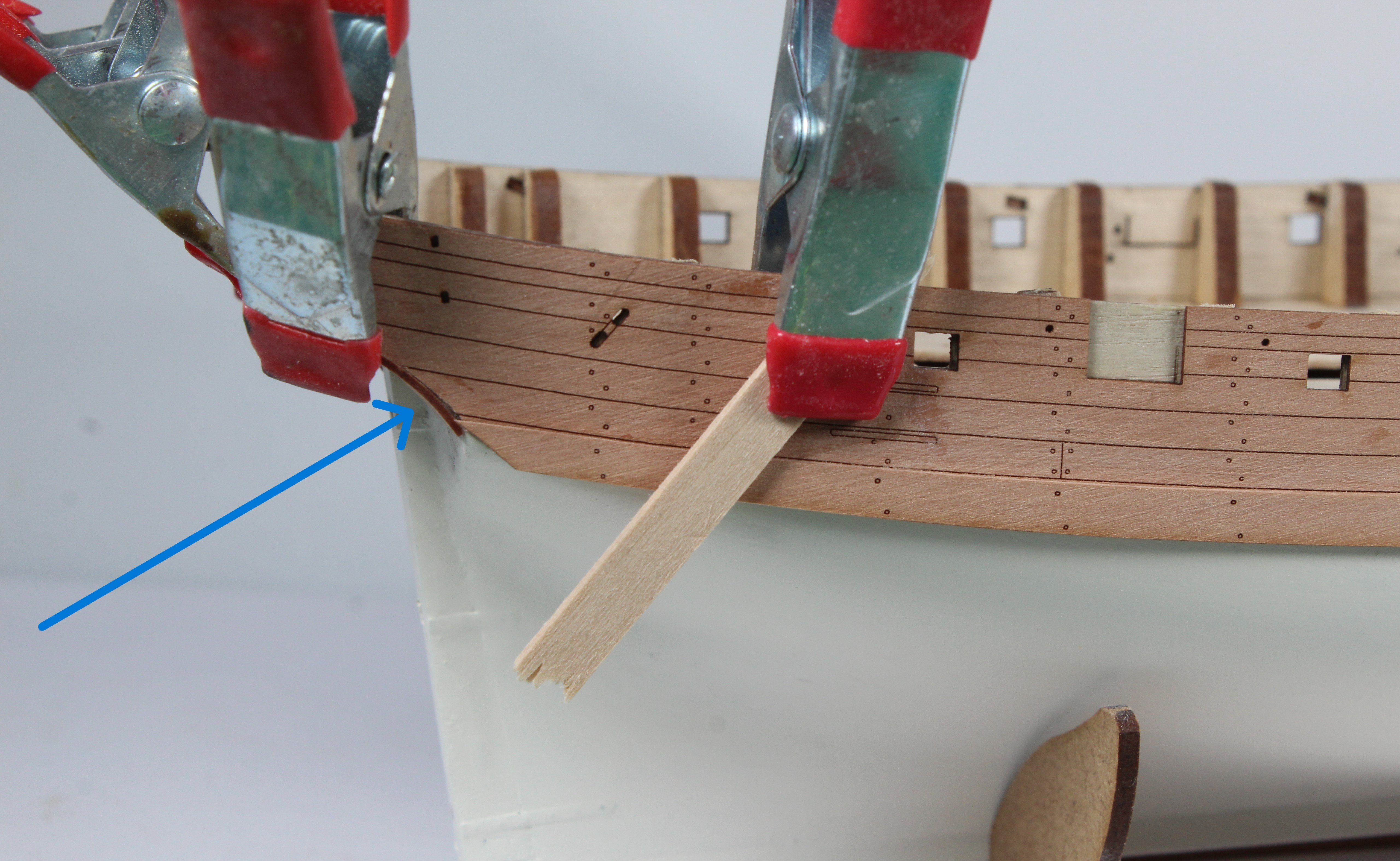
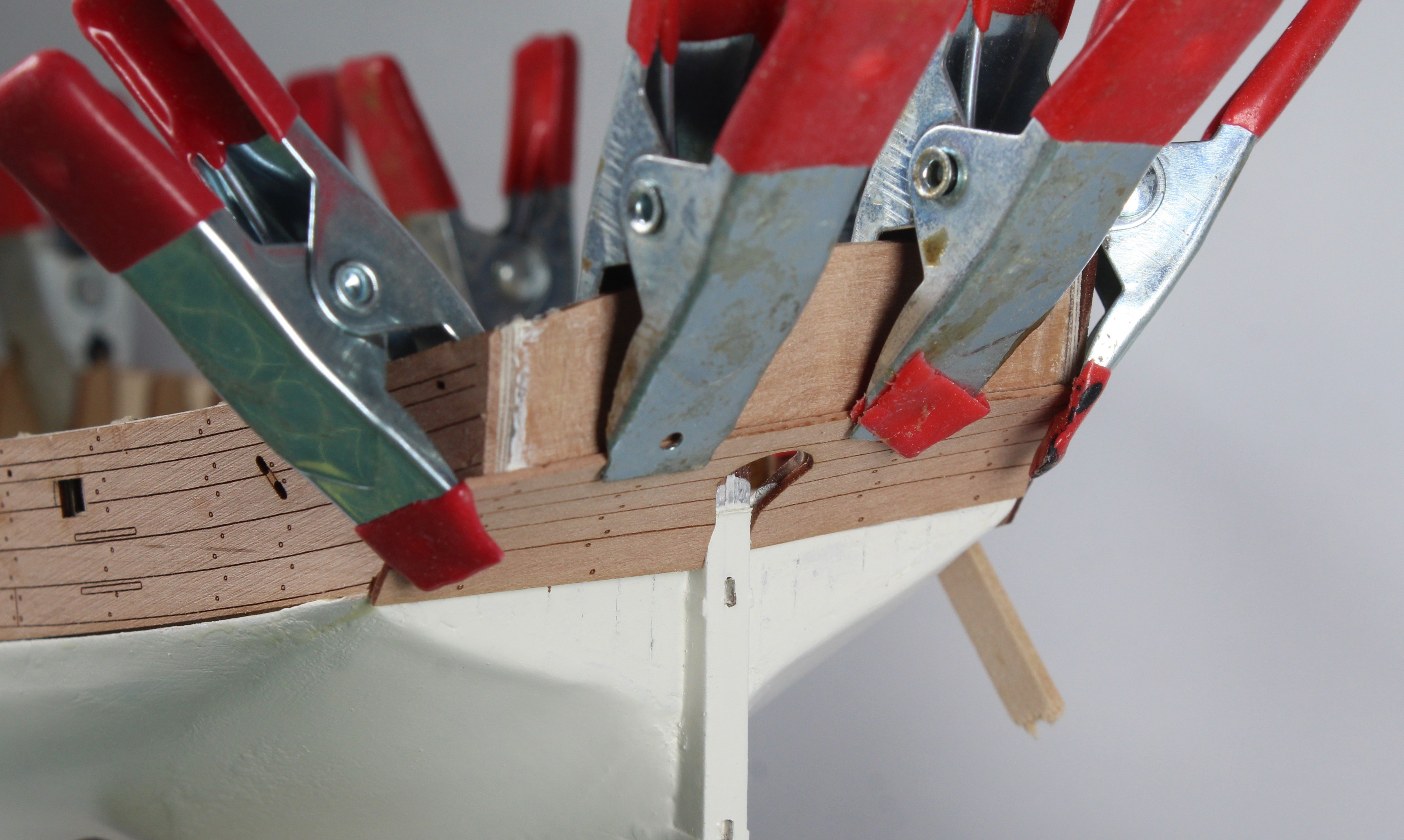
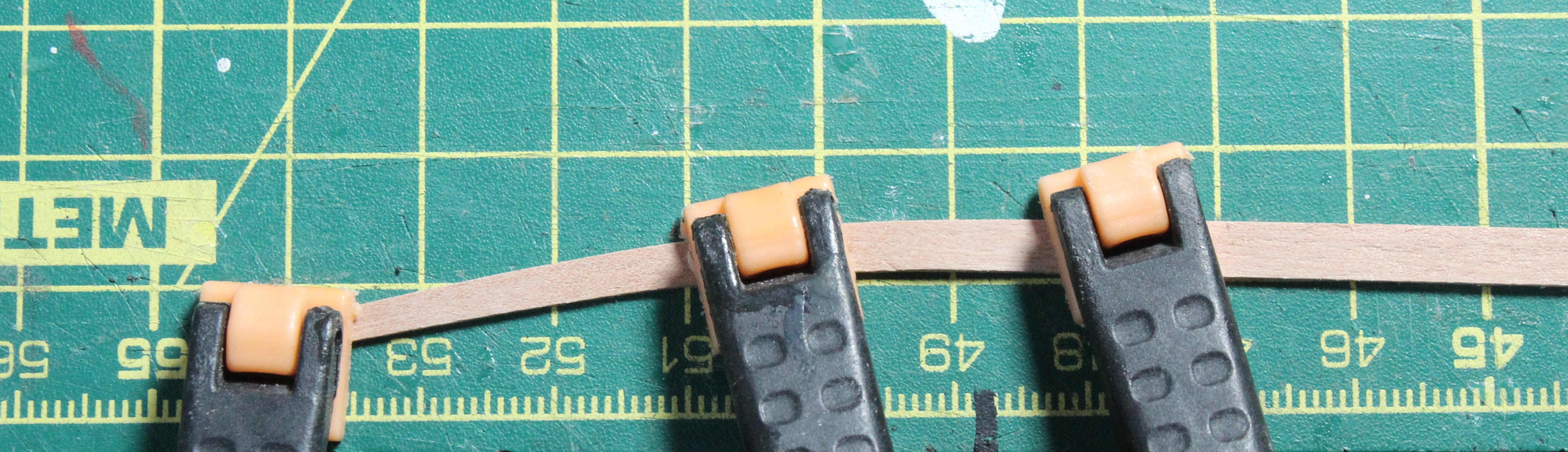
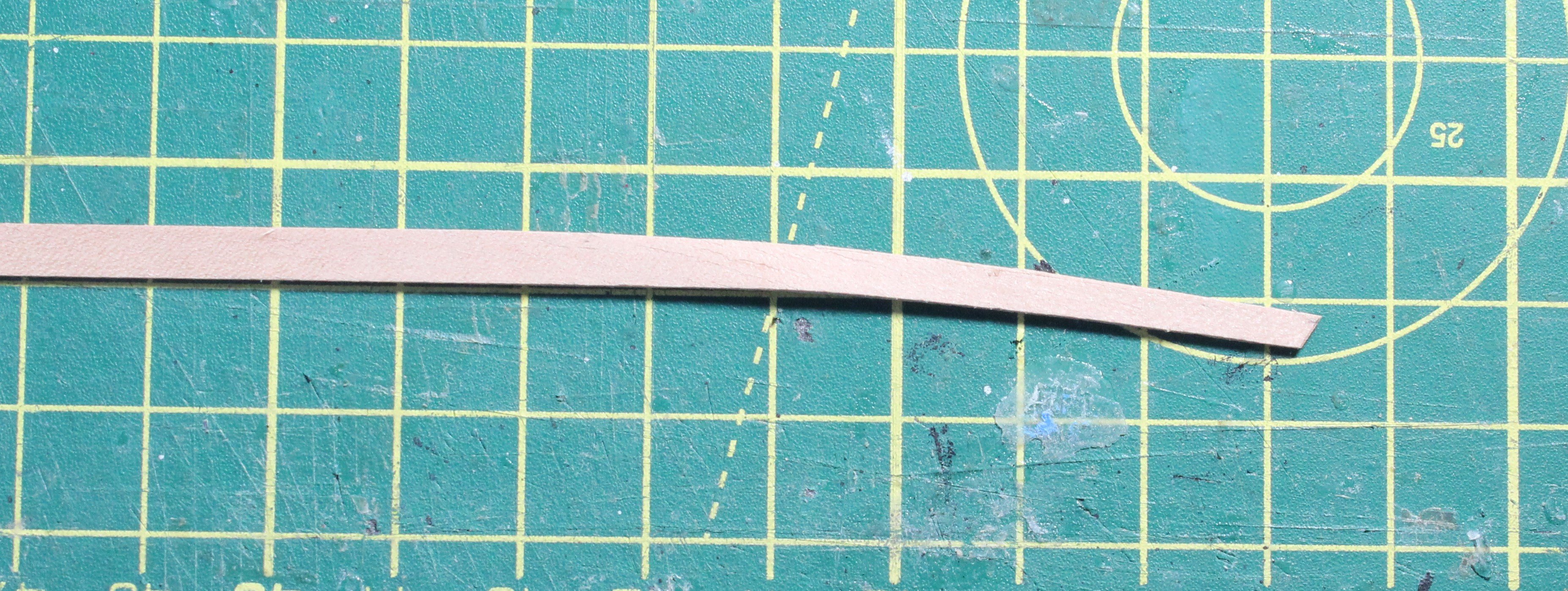
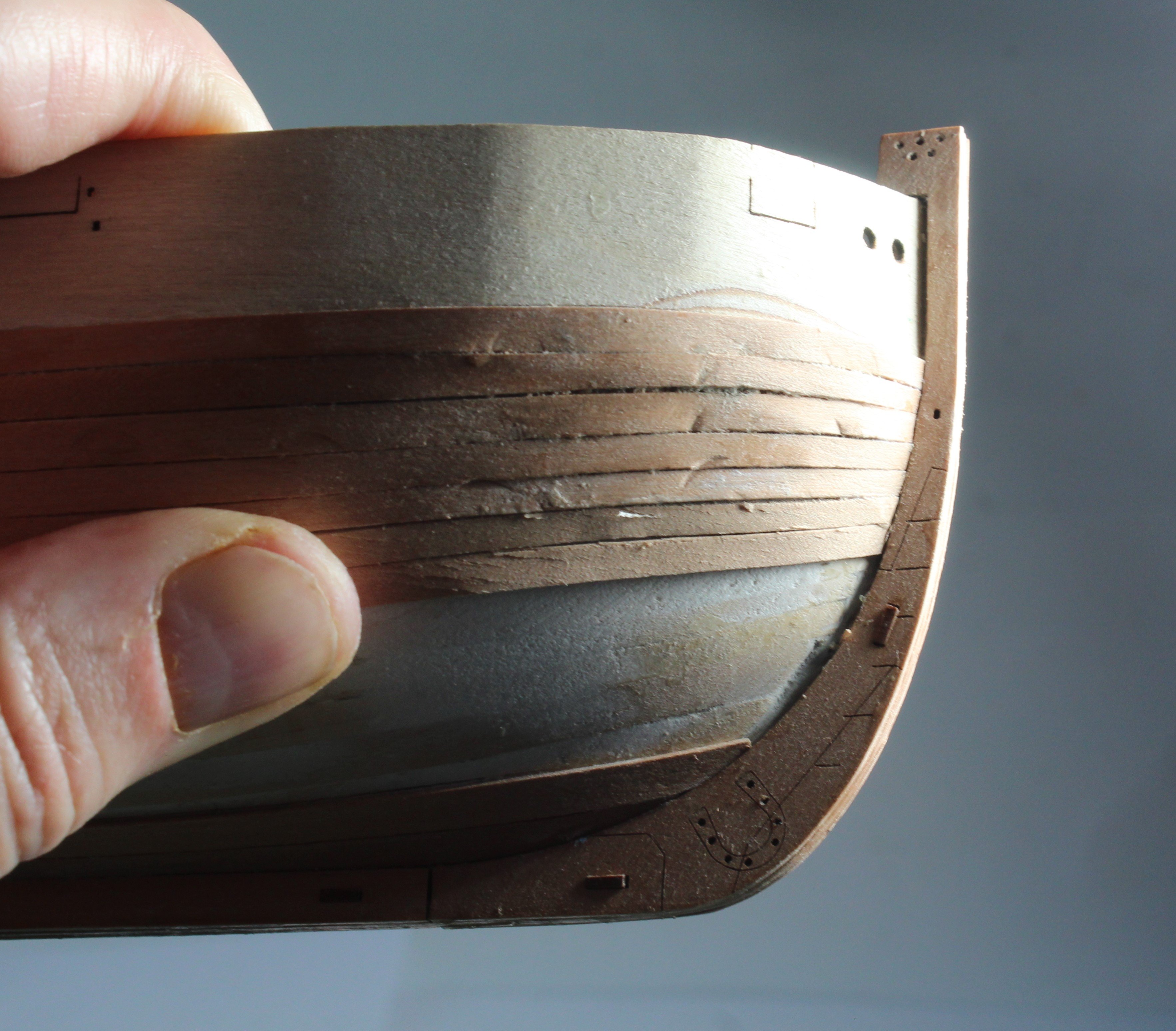
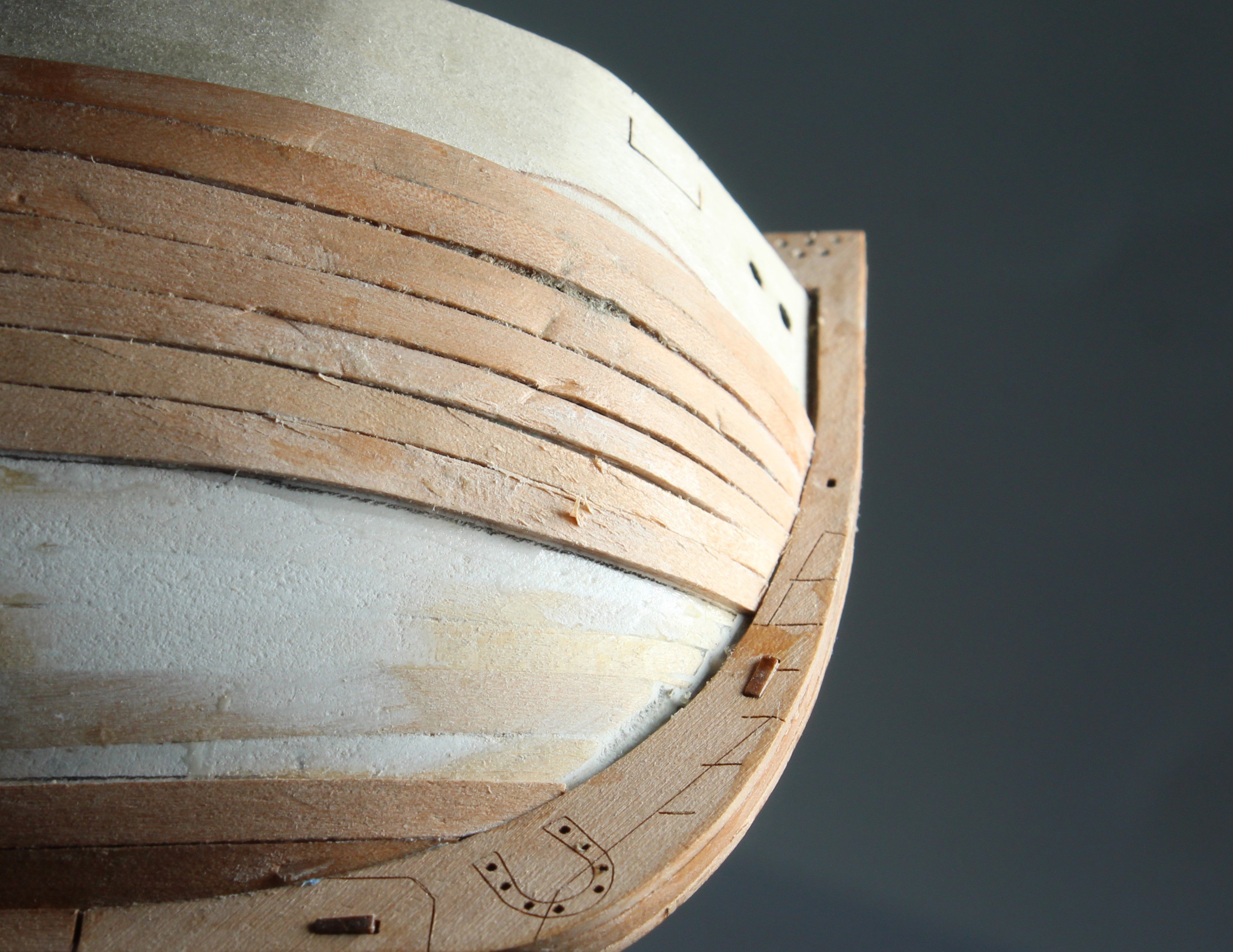
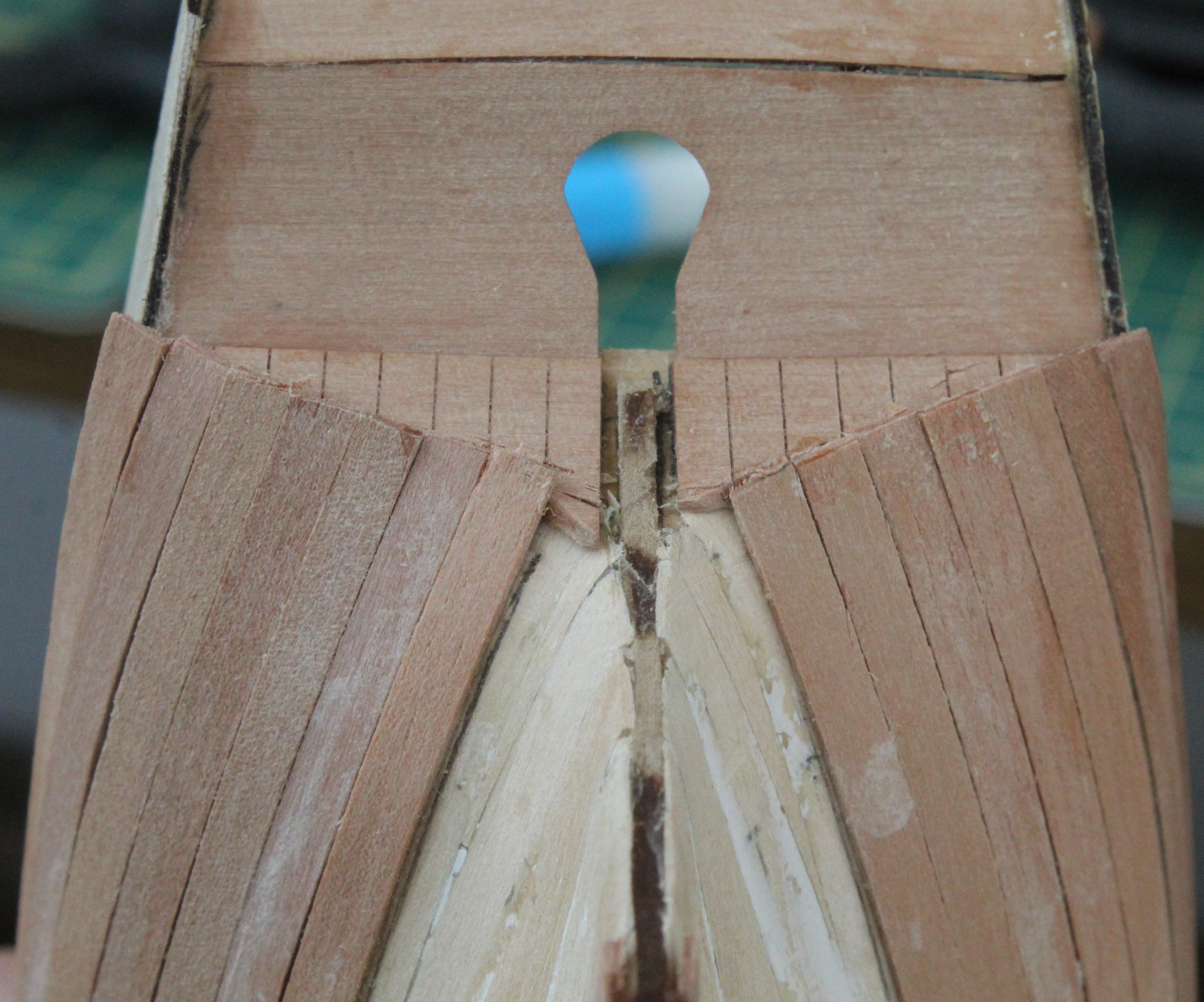
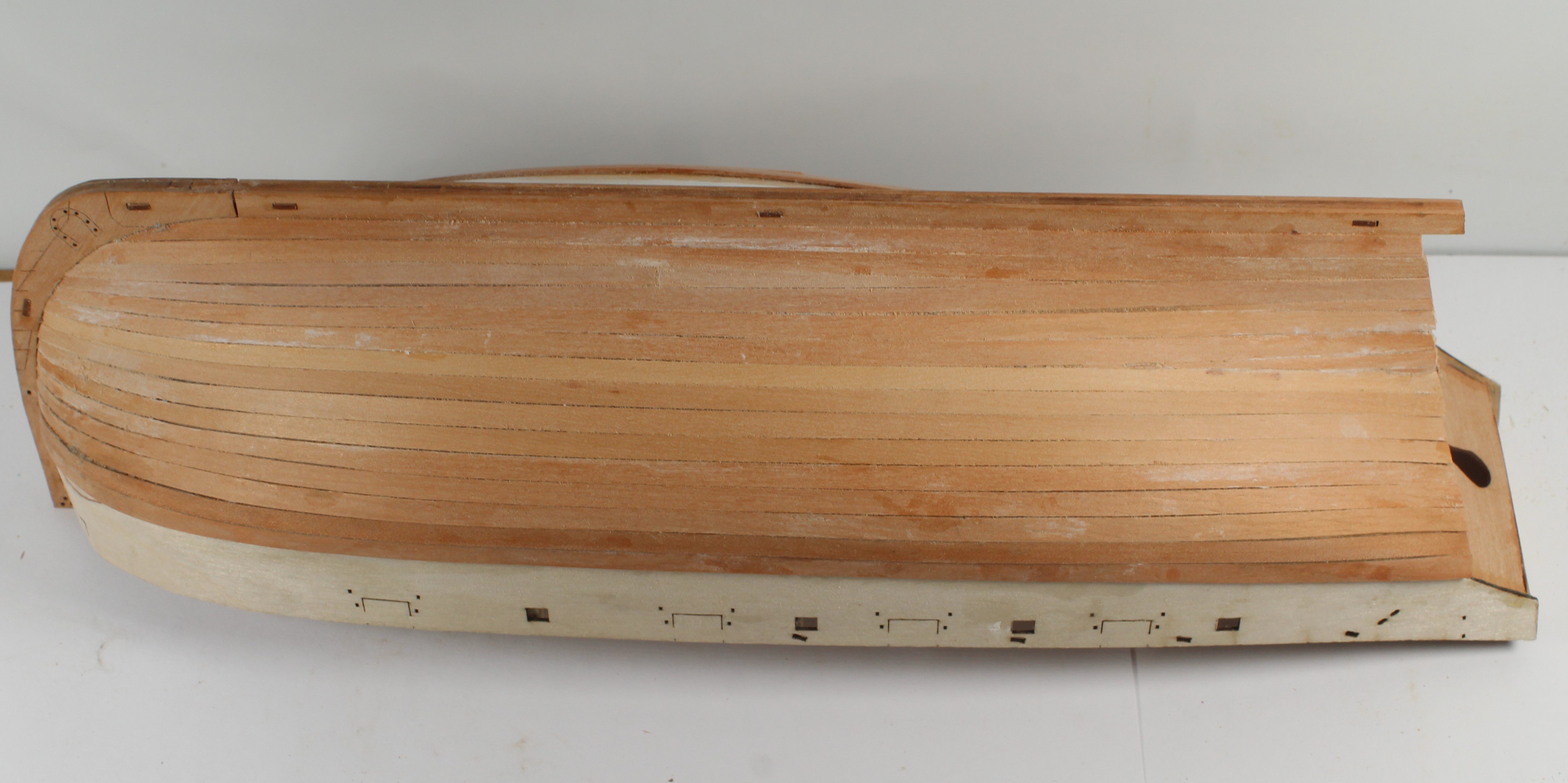
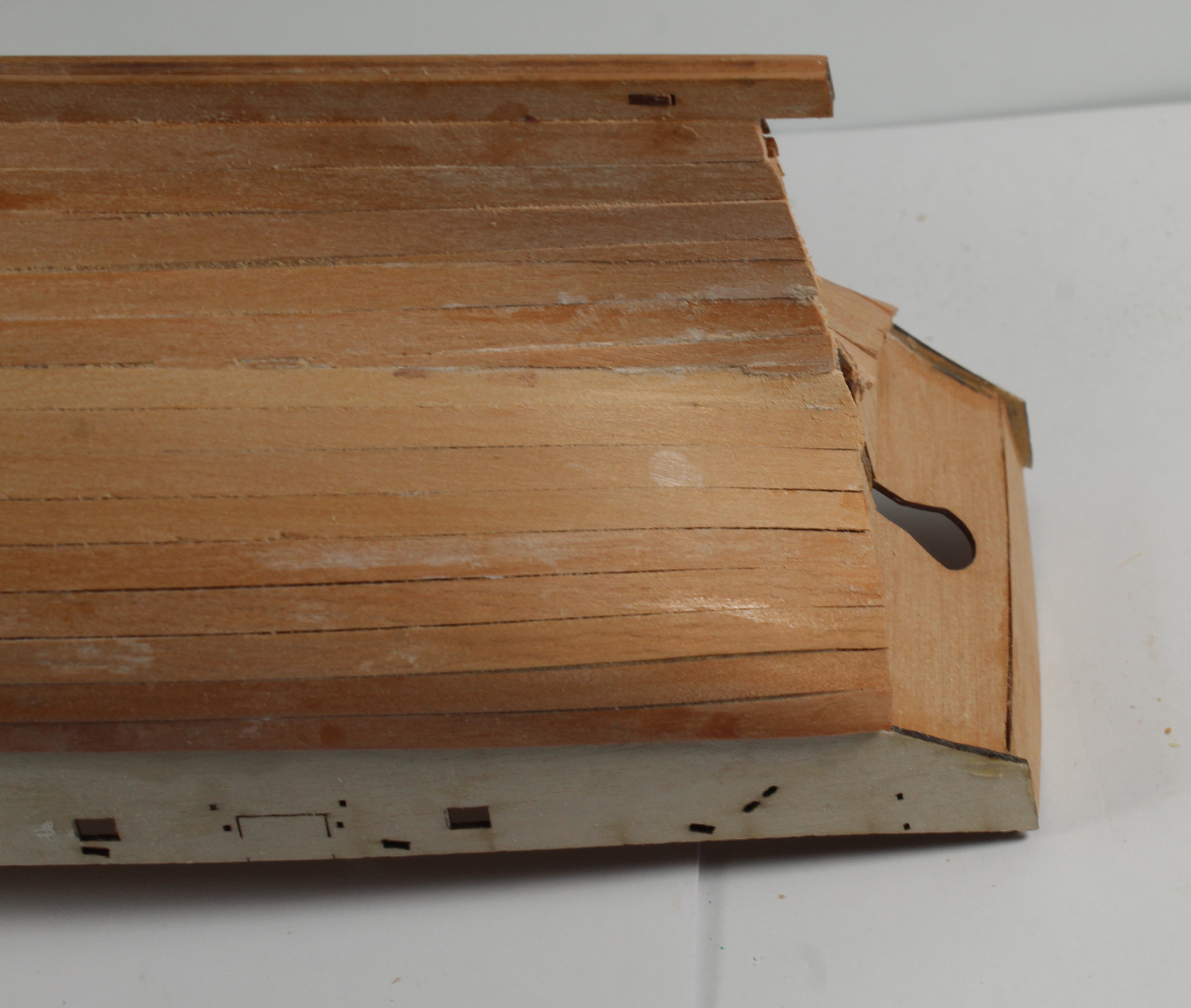
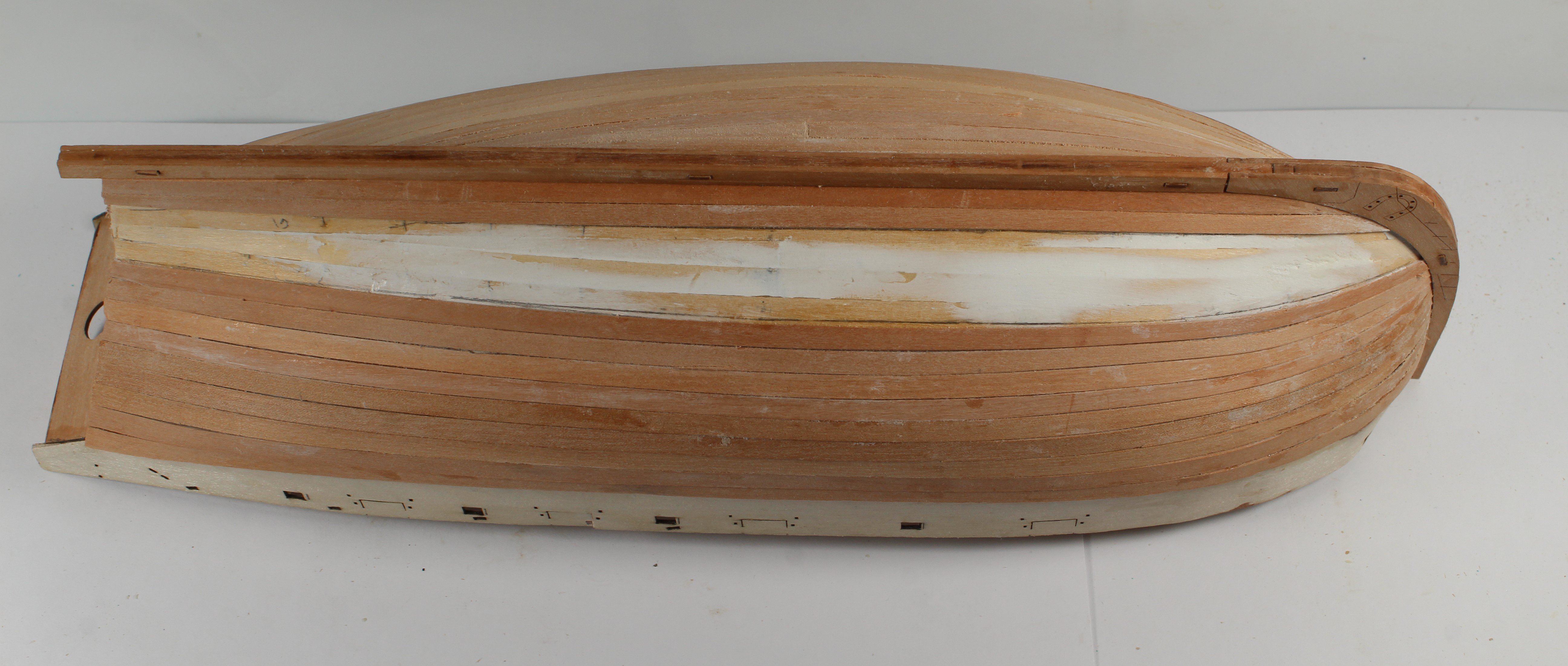
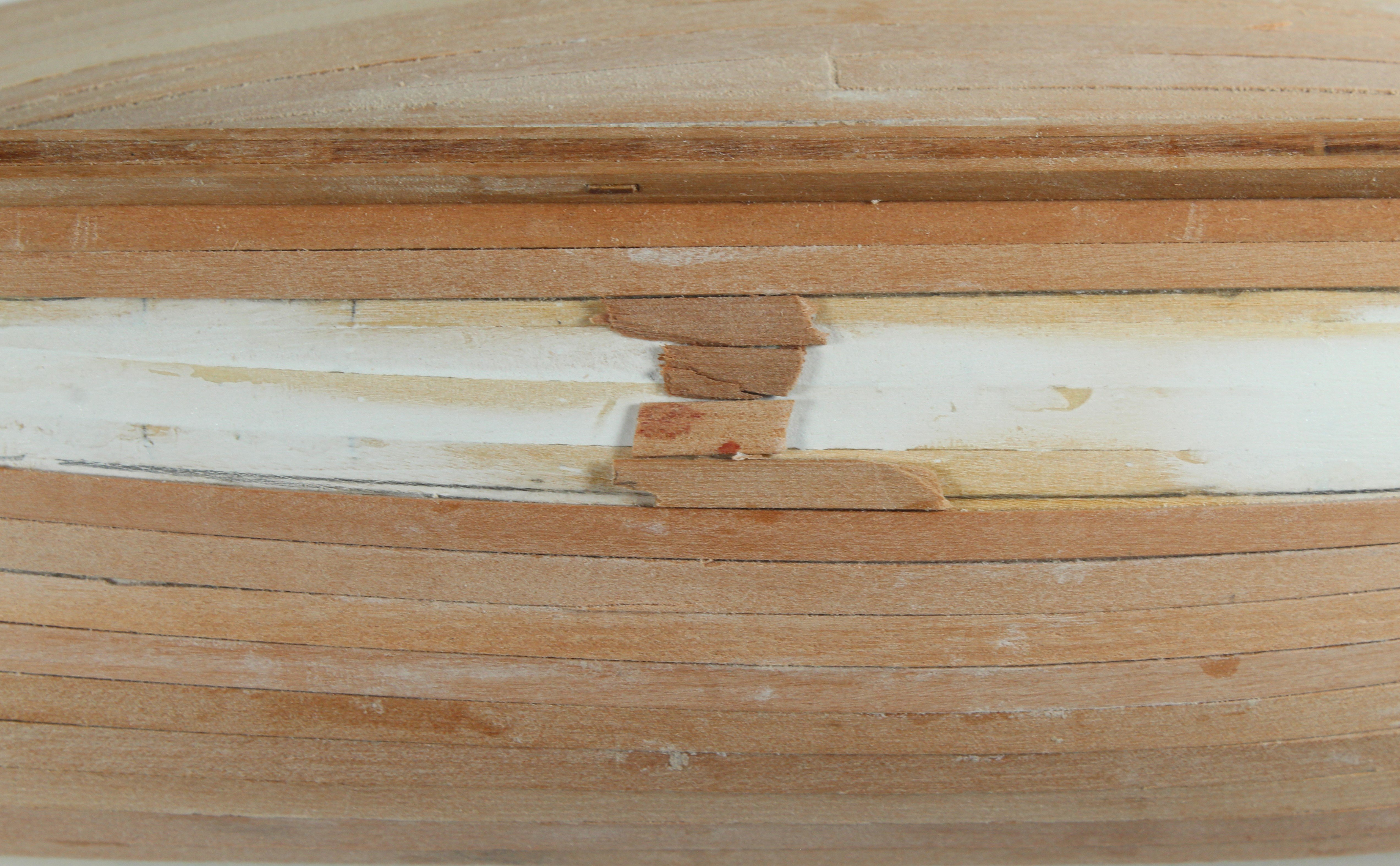
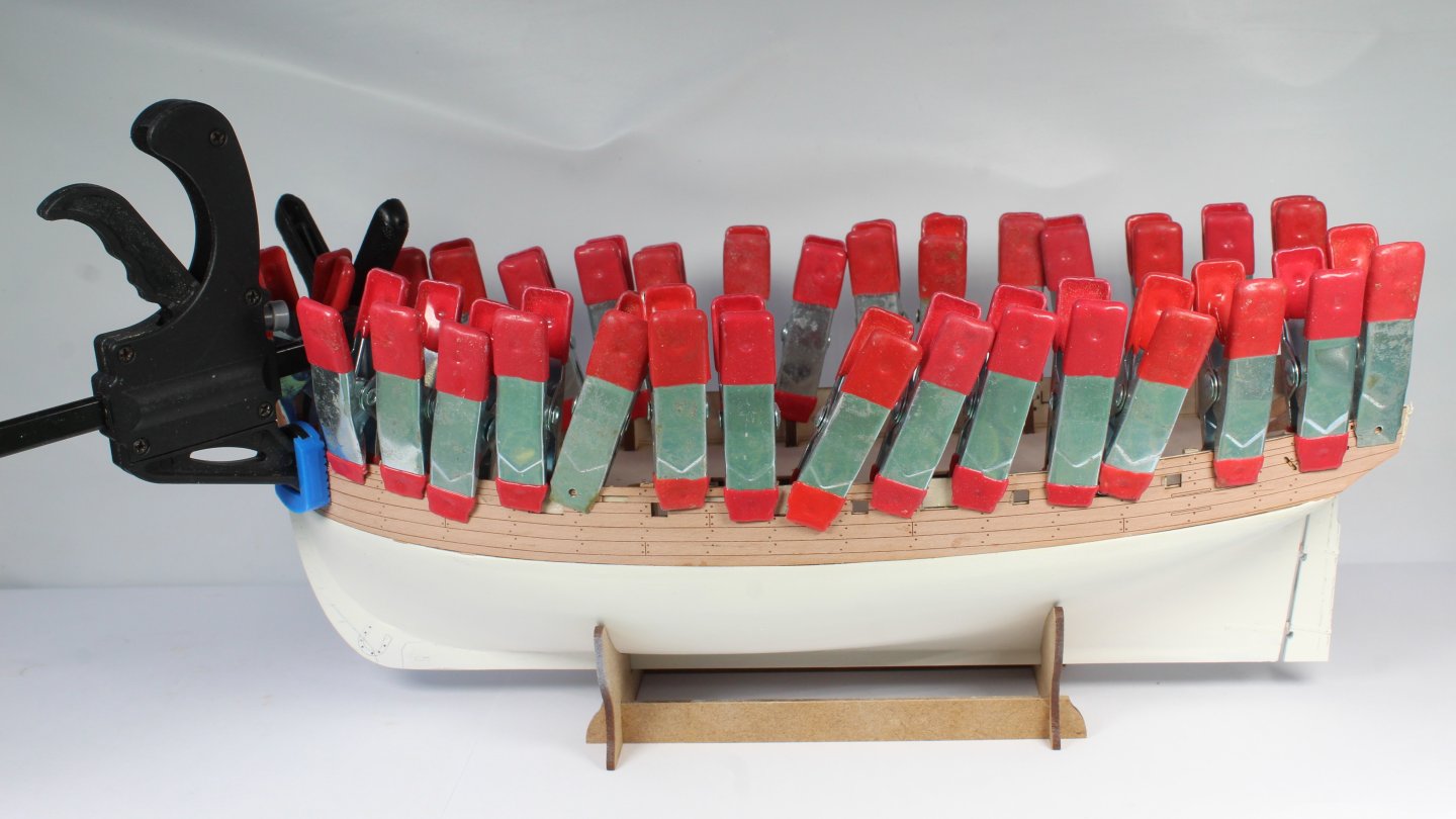
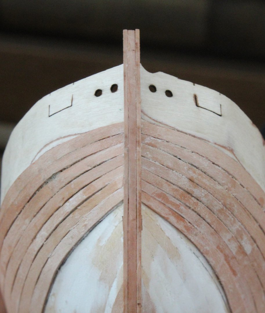
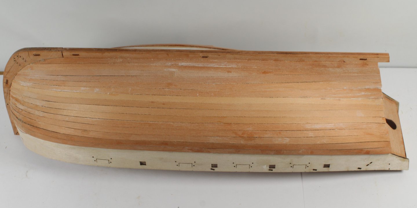
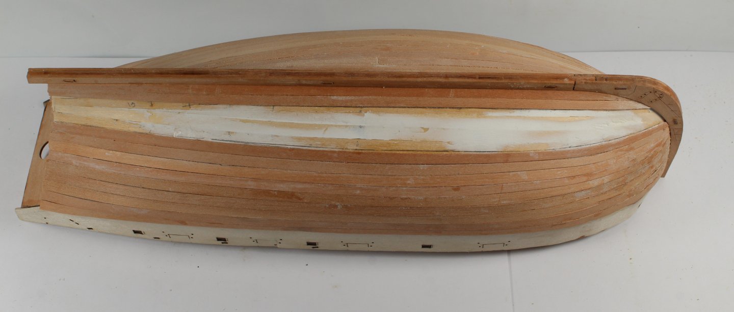
Stage 8 – Second Planking Hull Construction – Start of the Second Planking – Appling a lateral bend Build Steps 33 I have reverted to using Chuck’s lateral bending method as it is yielding much better results than the method used for the first couple of upper planks. After wetting the plank, I used clamps to apply a lateral bend. I then used a hairdryer to dry the plank so it hold’s its shape once the clamps are removed. Please refer to the first two photos below in respect to the above In the third photo below a laterally bent plank is being test fitted and this plank looks OK. Sometimes it is necessary to repeat the bending process to get the required lateral bend. Time Taken 5 mins Hull Construction – Start of the Second Planking – Adding a plank Build Steps 33 Before fitting the plank, The area where the ca glue needs to be added is marked. This is shown in the first photo below. The plank is dampened, as this helps the adhesion with ca glue. Ca glue is then added to the hull along the marked area. Starting at the bow the plank is pushed into the rabbet and then is pressed down working back toward the stern, ensuring any excess ca glue is wiped away. The final three photos show the end result after 7 upper planks have been fitted to both sides. Time Taken 10 mins Hull Construction – Completing Second Planking – Starboard Side Build Steps 33 A total of 15 off full planks were required for the second planking on the starboard side. I am really pleased with the end result. Although more work is required to improve my technique, this is without my best work with regards to adding the second planking. Time Taken 60 mins Hull Construction – Completing Second Planking – Port Side Build Steps 33 I have added 11 planks to the port side, so there are 4 more planks to fit to complete this task. As can be seen on the second photo the gap to fill, at the midship section, requires exactly 4 planks. Time Taken 60 mins


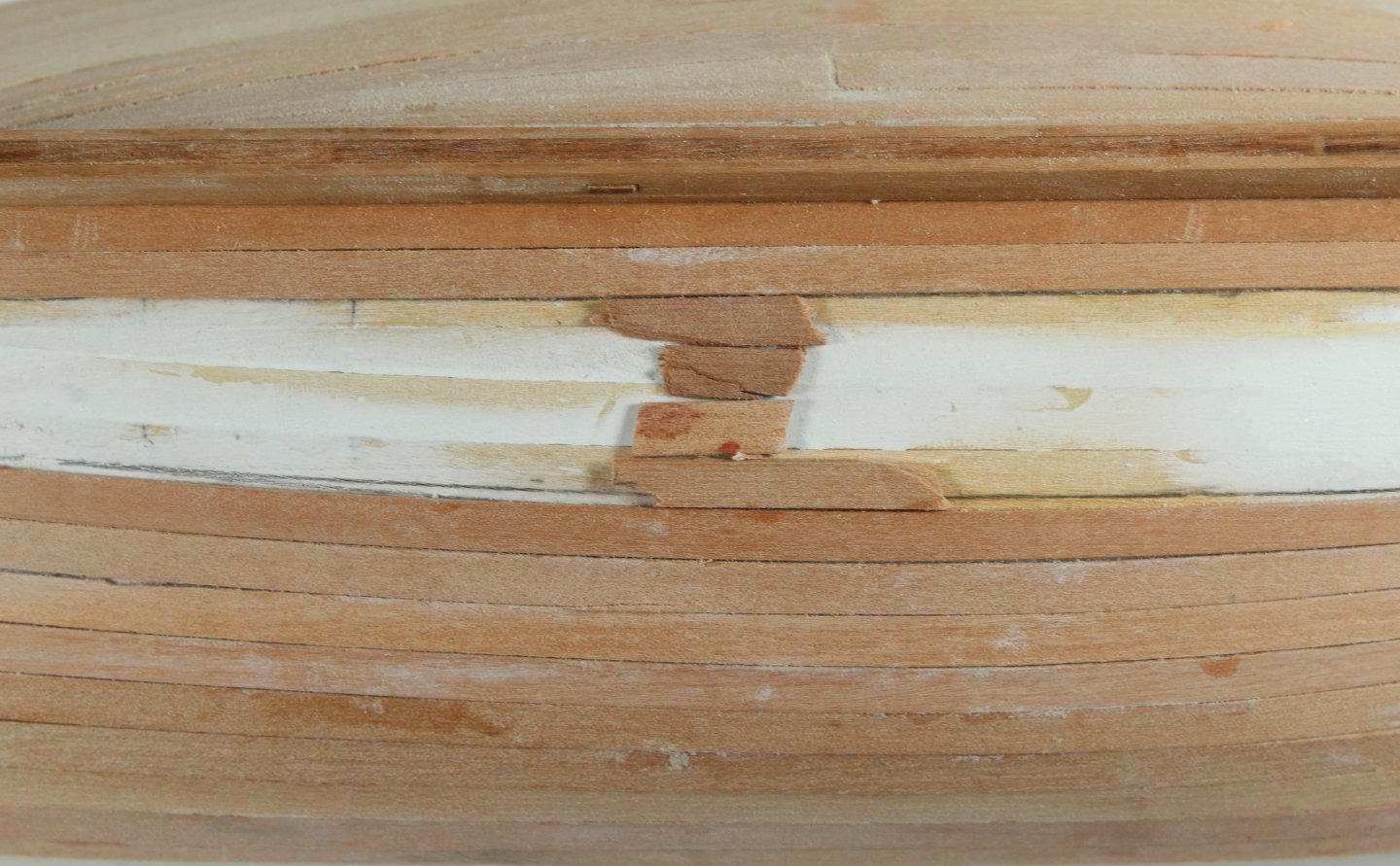
- 43 replies
-
- 9
-
-
- Vanguard Models
- Sherbourne
- (and 1 more)