Glenn-UK
-
Posts
3,176 -
Joined
-
Last visited
Content Type
Profiles
Forums
Gallery
Events
Everything posted by Glenn-UK
-
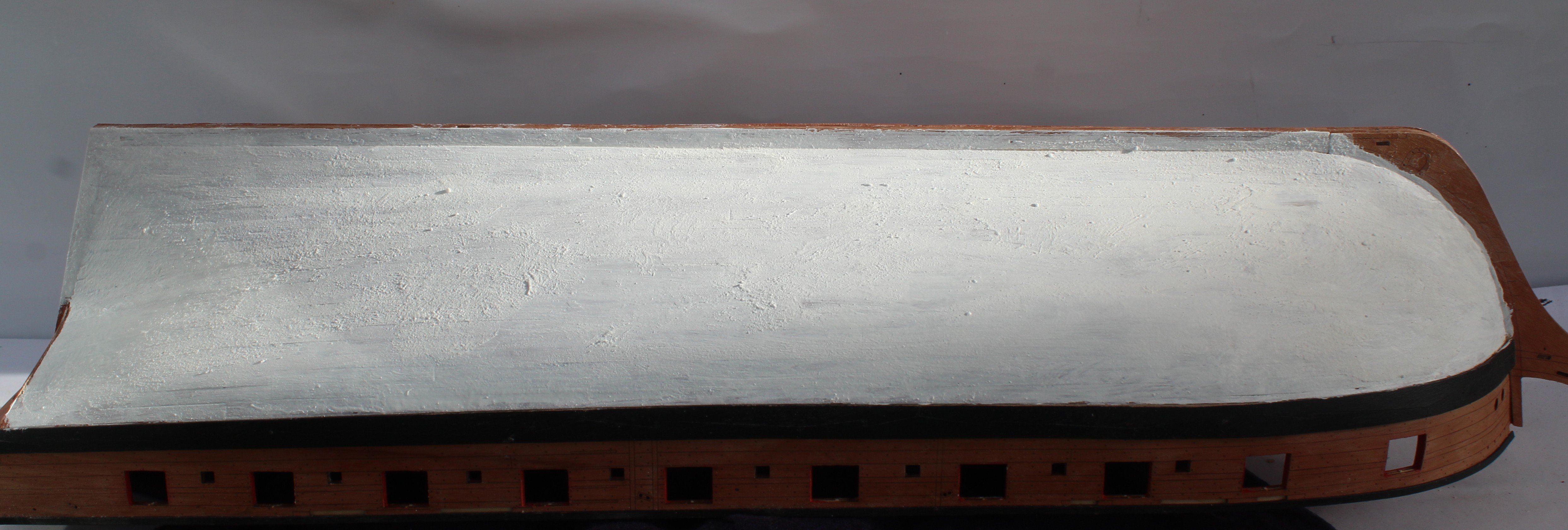
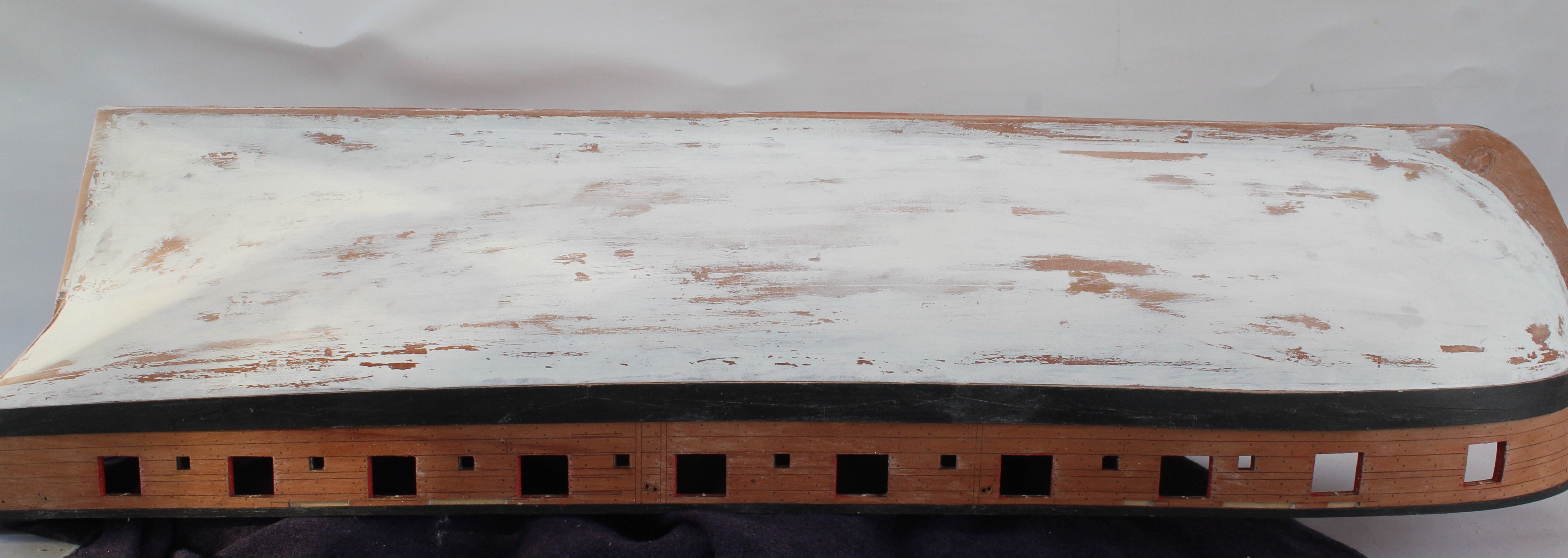
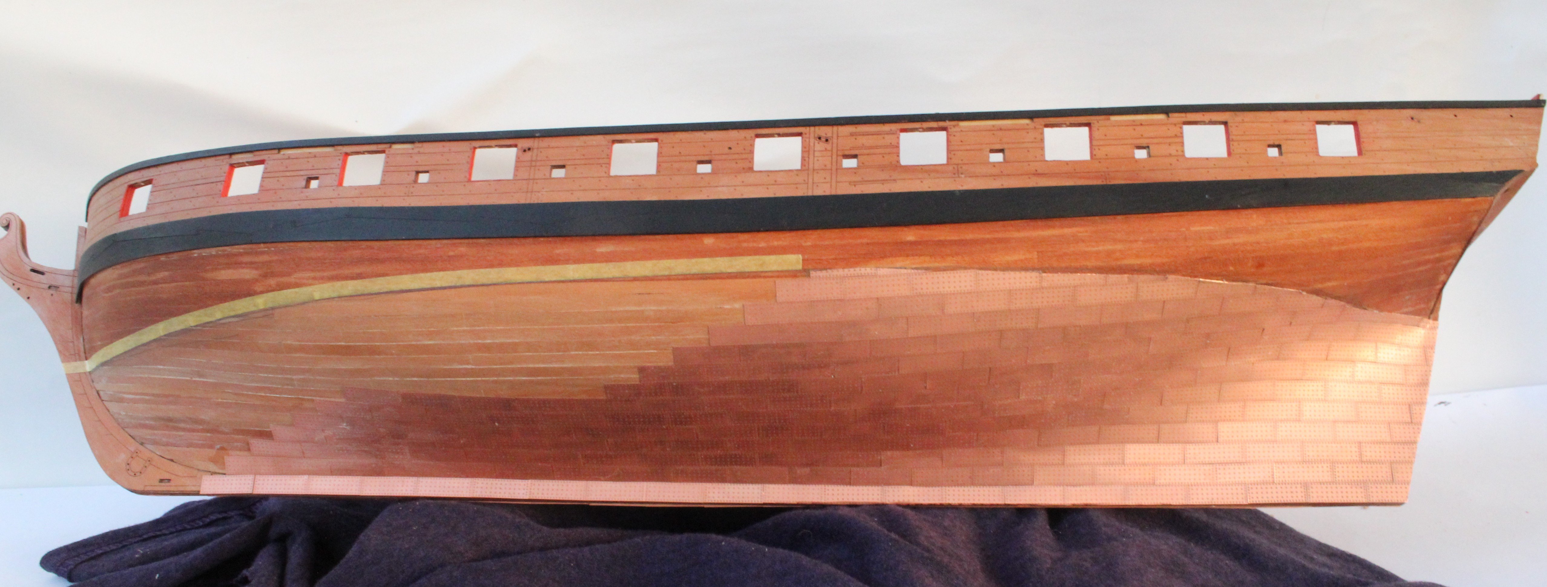
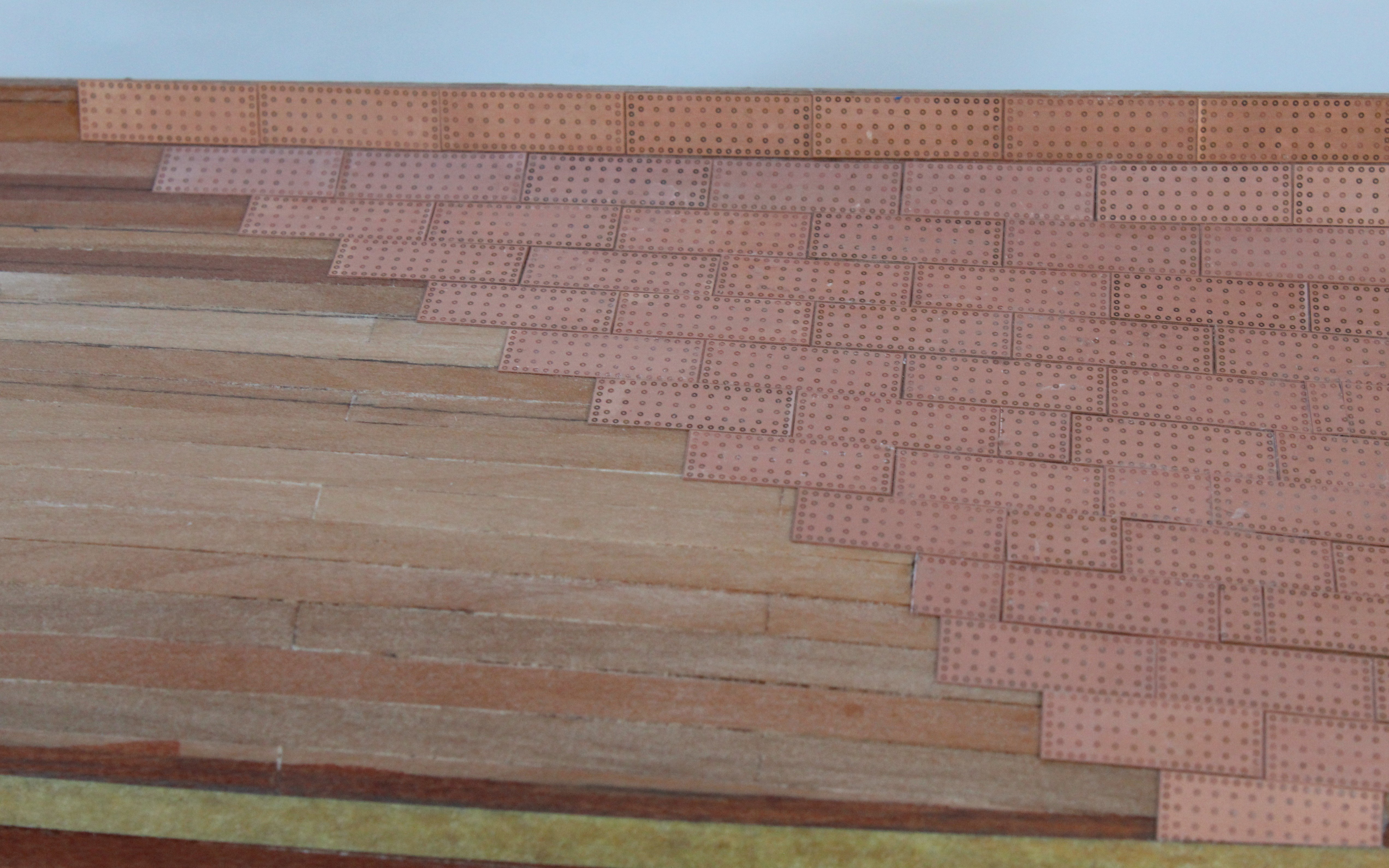
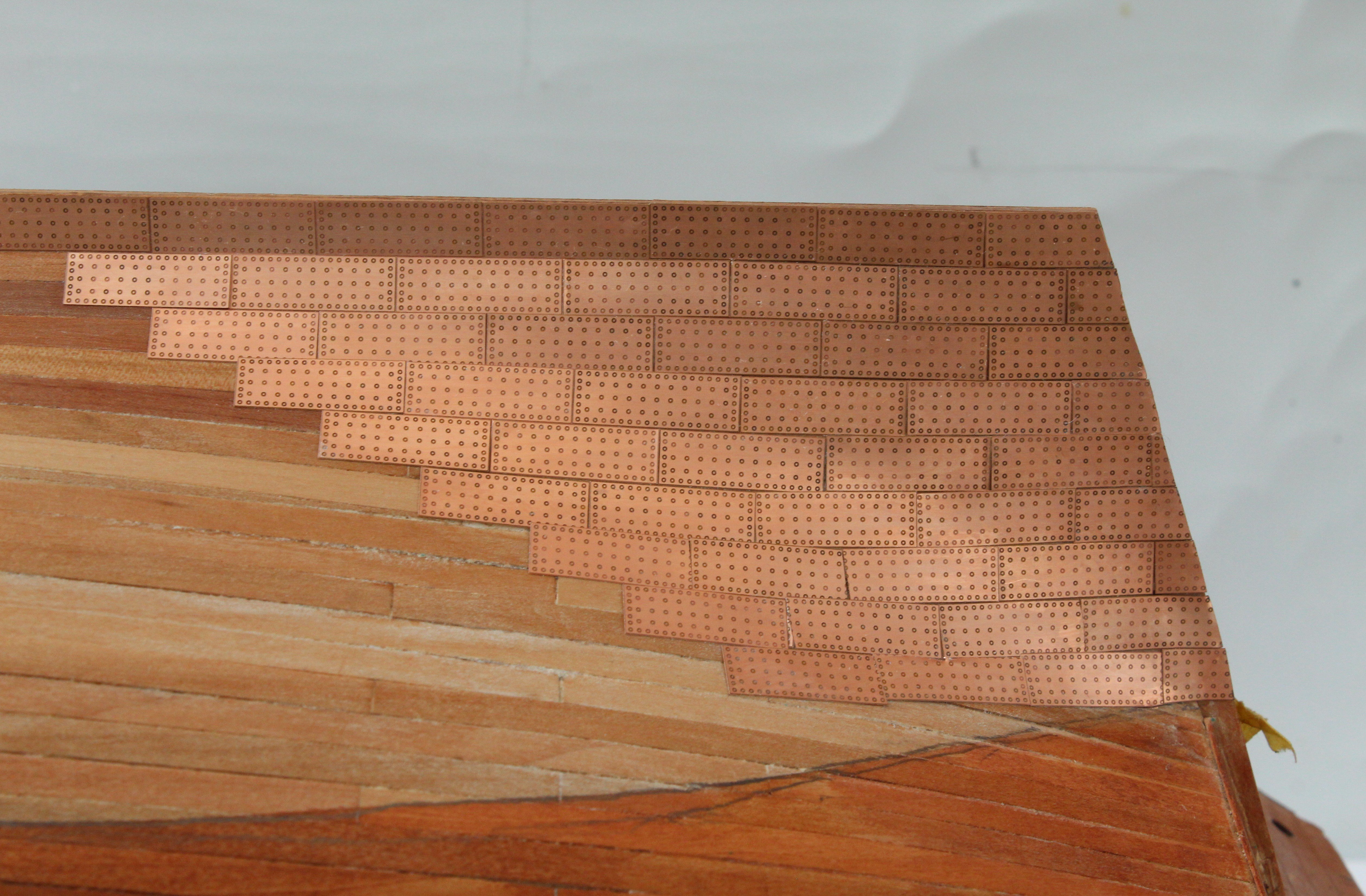
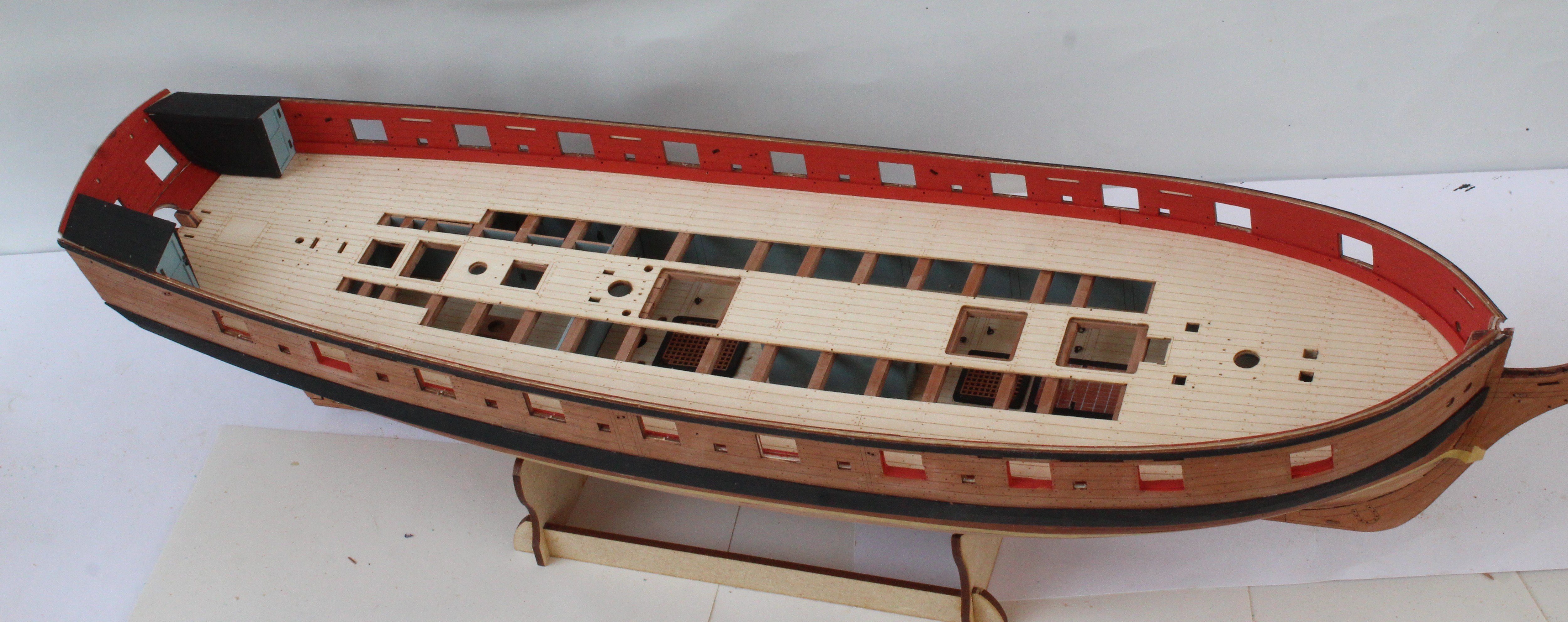
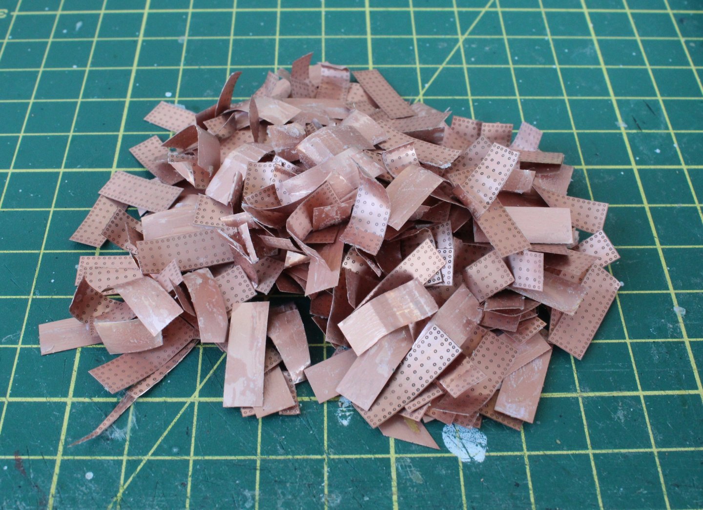
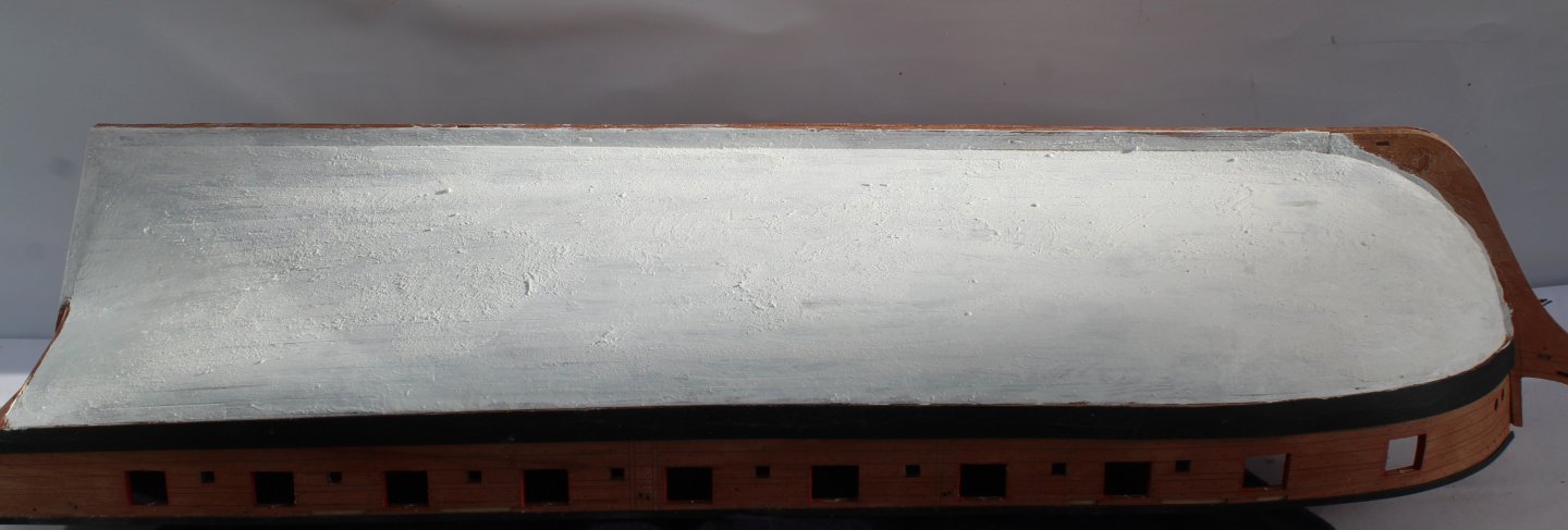
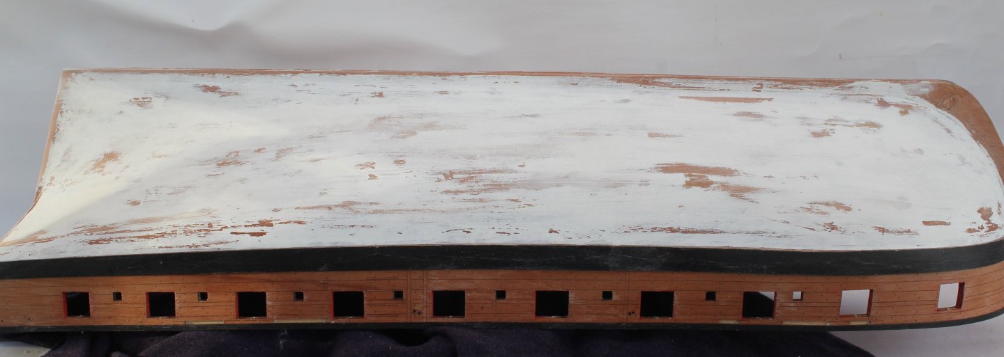
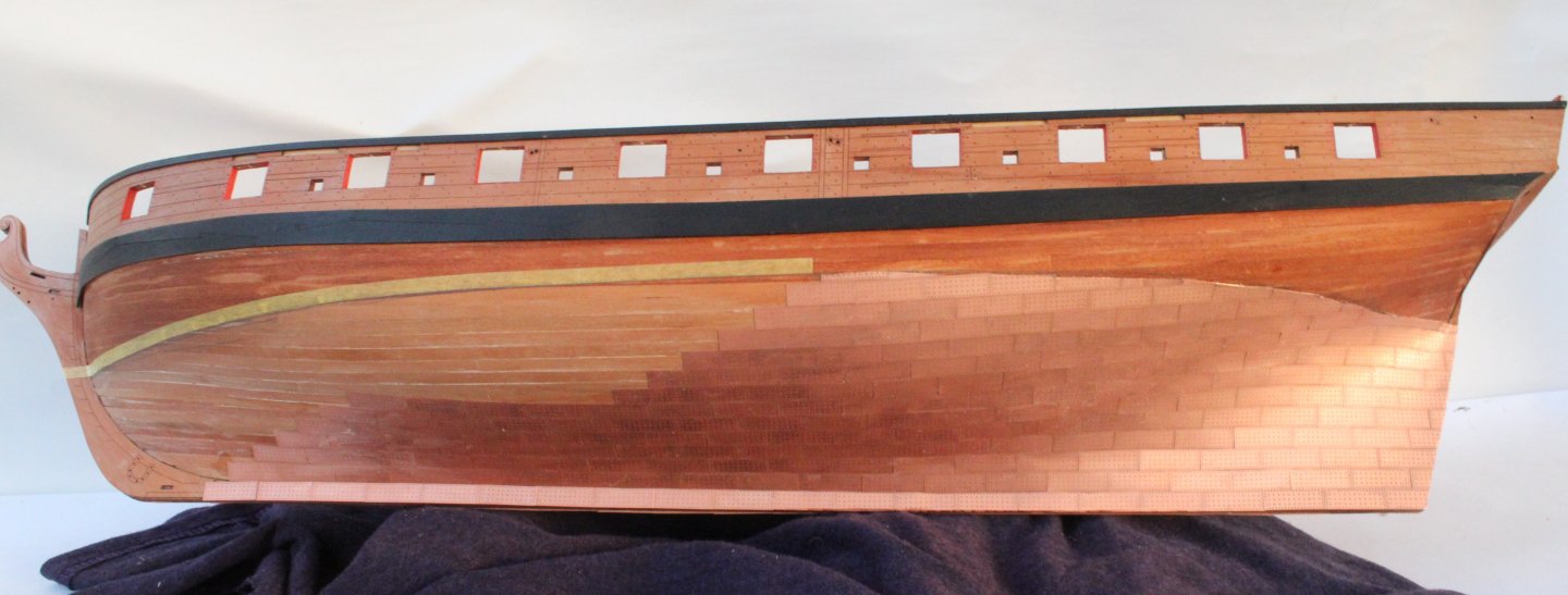
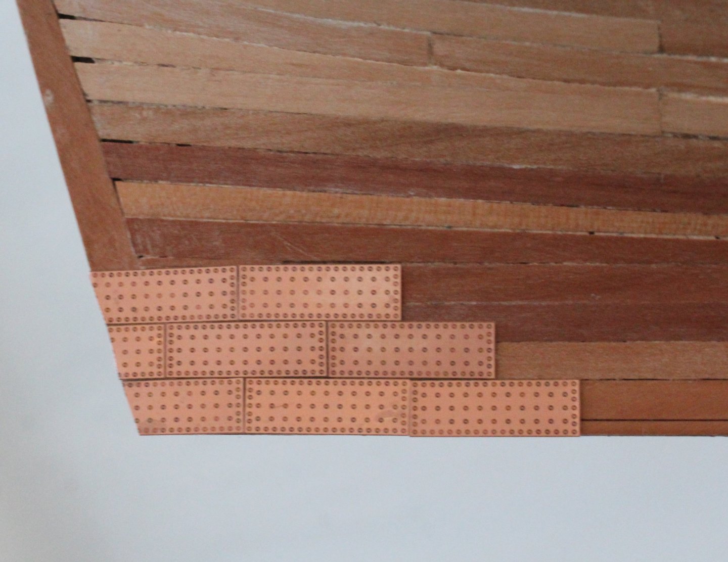
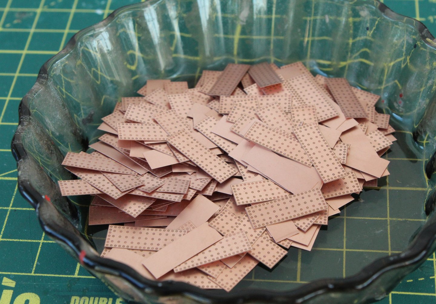
 After another day of copper plates not adhering to the hull I finally took the decision to remove all the copper plates. With the exception of a few copper plates they fell off with a quick flick of a craft knife blade and only took approx. 15 minutes to complete. A big pile of used copper plates. I probably have enough spare copper plates to redo however as I have not got to the root of the problem I have decided to paint the hull. After sanding the hull to remove all traces of any excess ca glue I brushed on some white paint which highlighted a few areas which need some attention. I brushed on some brushed diluted water filler where necessary, as can be seen in the next photo. In the final photo the hull has been sanded smooth and I am happy with how it looks so I can now tape up the hull and start painting. My current thinking is I will use red oxide below the waterline then to have a thin black band for the waterline and to paint the section between the waterline and wales either yellow ochre or white.
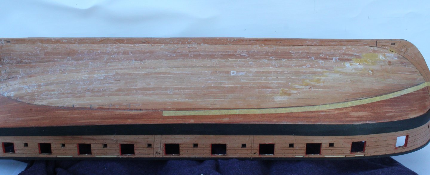
- 241 replies
-
- 10
-

-
- Vanguarrd Models
- Harpy
- (and 1 more)
-
Hello Bob. I have tried two types of ca, the issue seems to be the hull as the copper plates do adhere to other surfaces.
- 241 replies
-
- 1
-
-
- Vanguarrd Models
- Harpy
- (and 1 more)
-
Hello Maurice I did clean the back of the plates. I am bemused. Cheers Glenn
-
Thanks. I have tried painting and WOP. This morning I have cleaned the area and applied a new WOP coat and have been able to add a few more copper plates, but some still refuse to stick.🤨
-
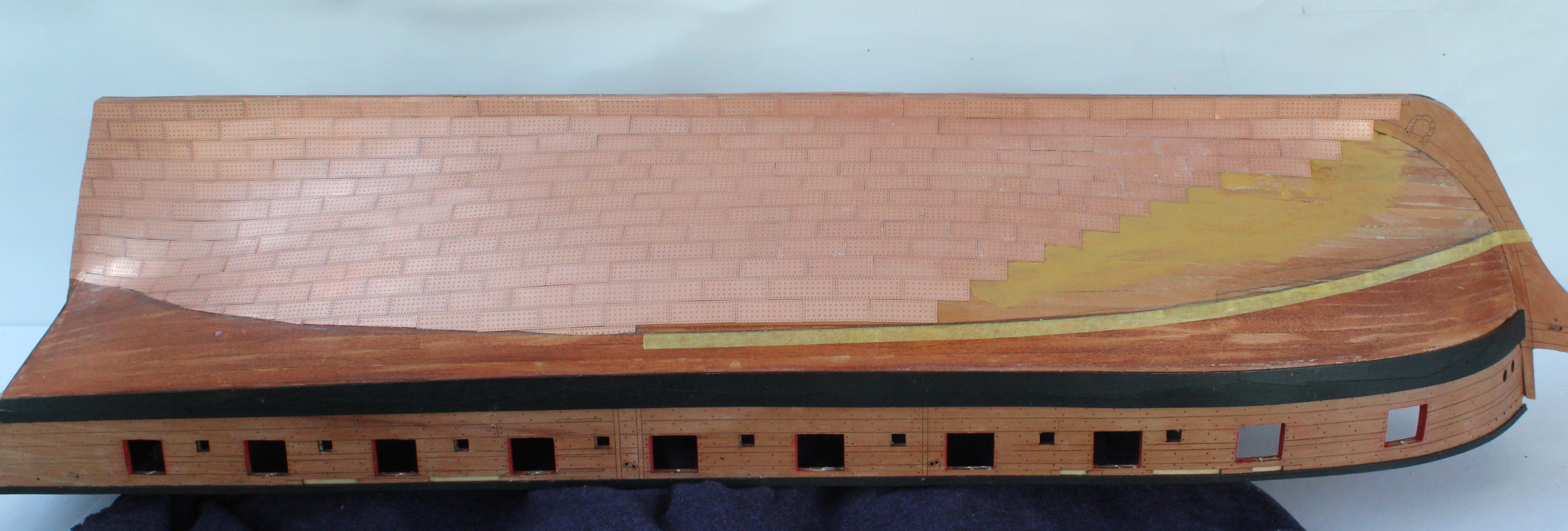
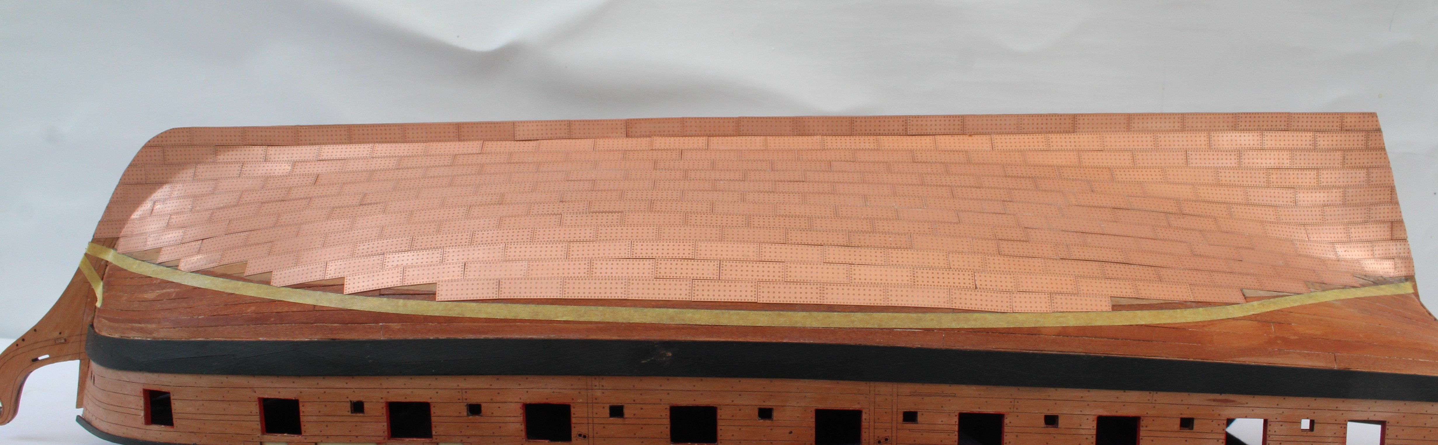
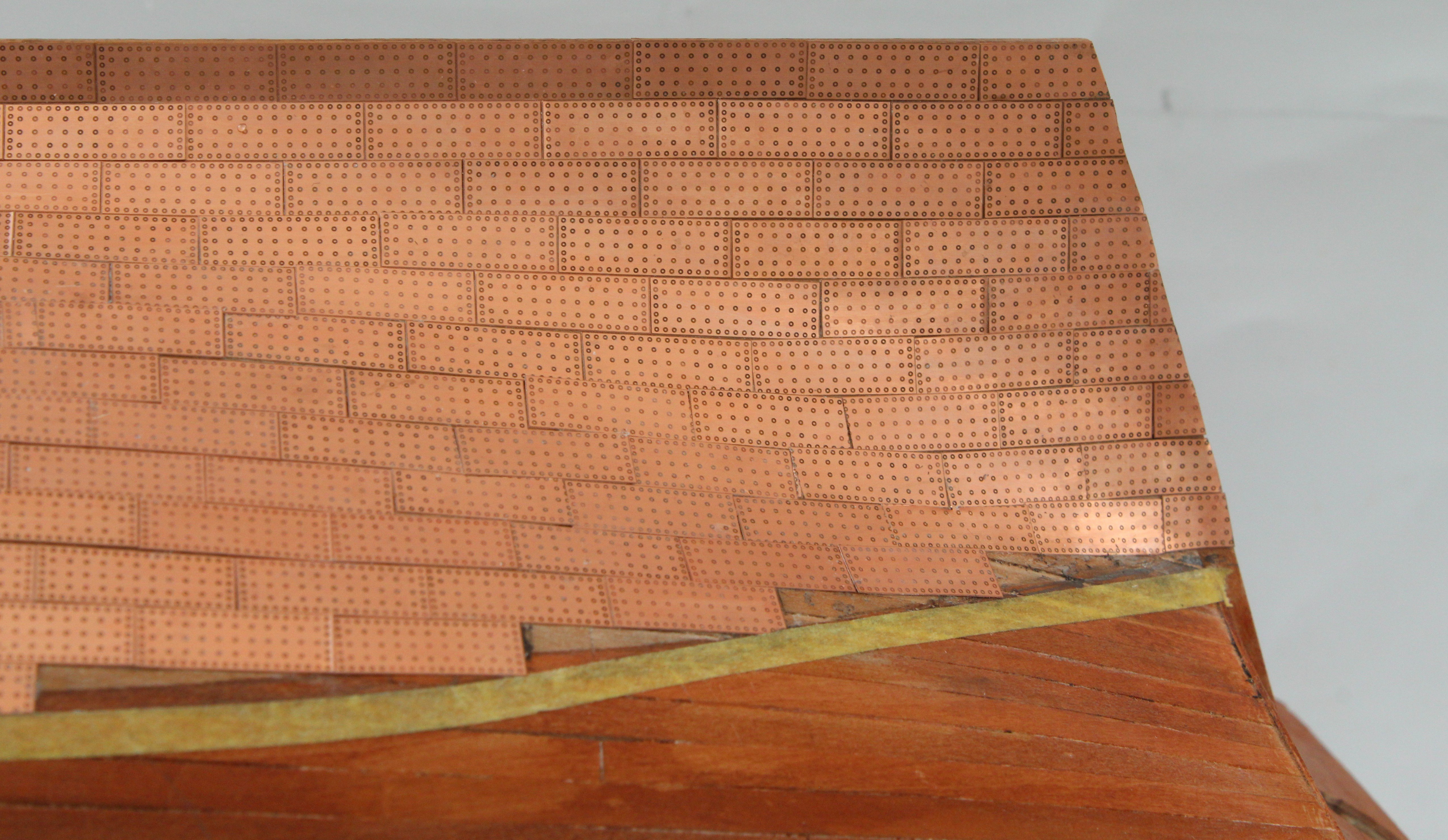
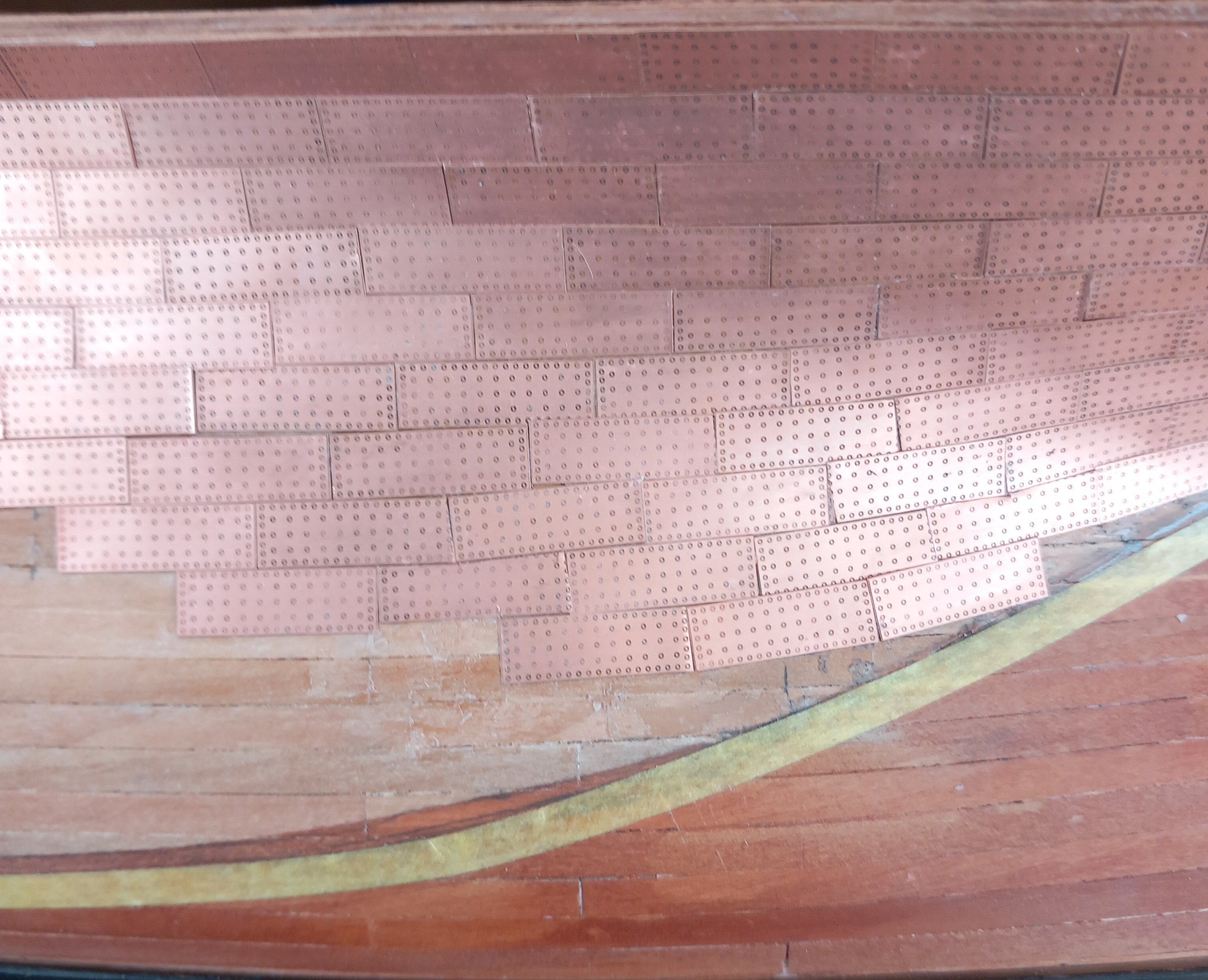
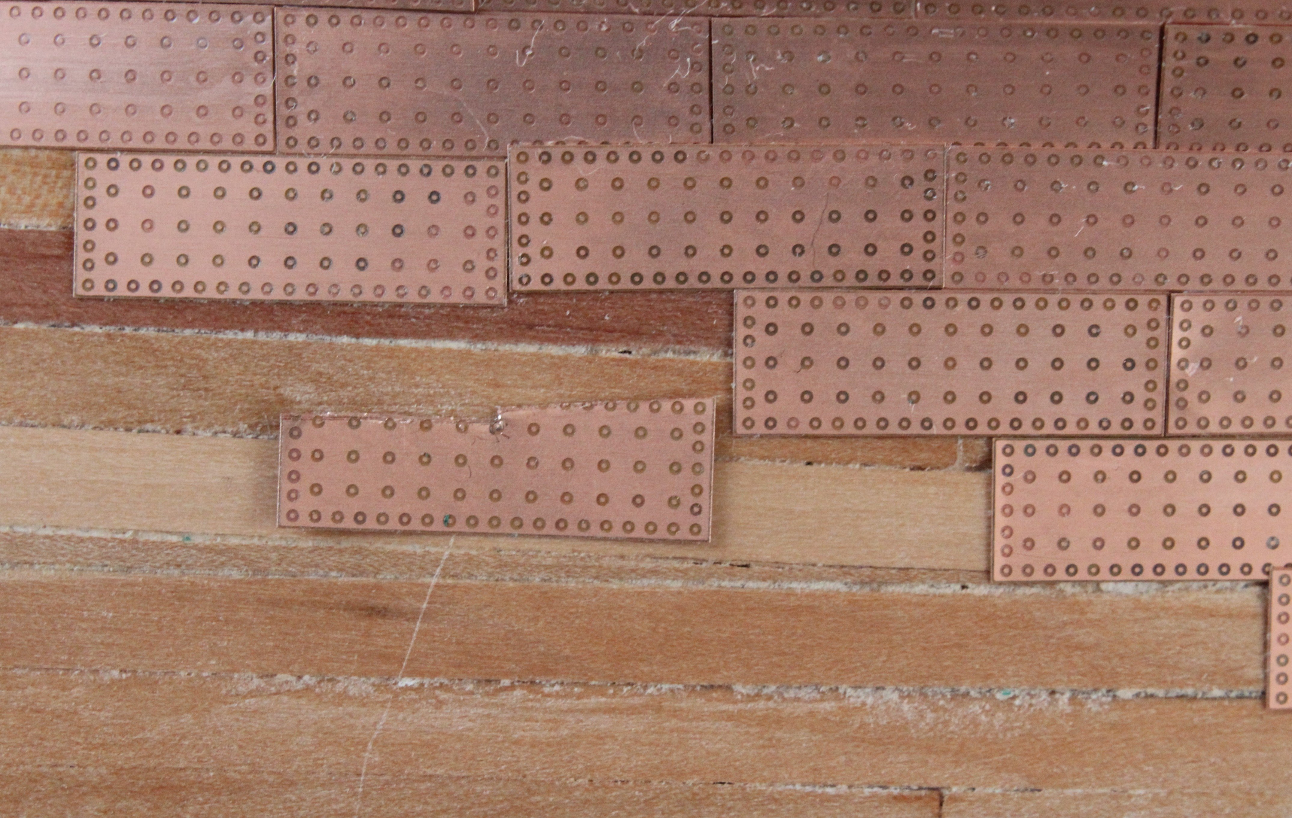
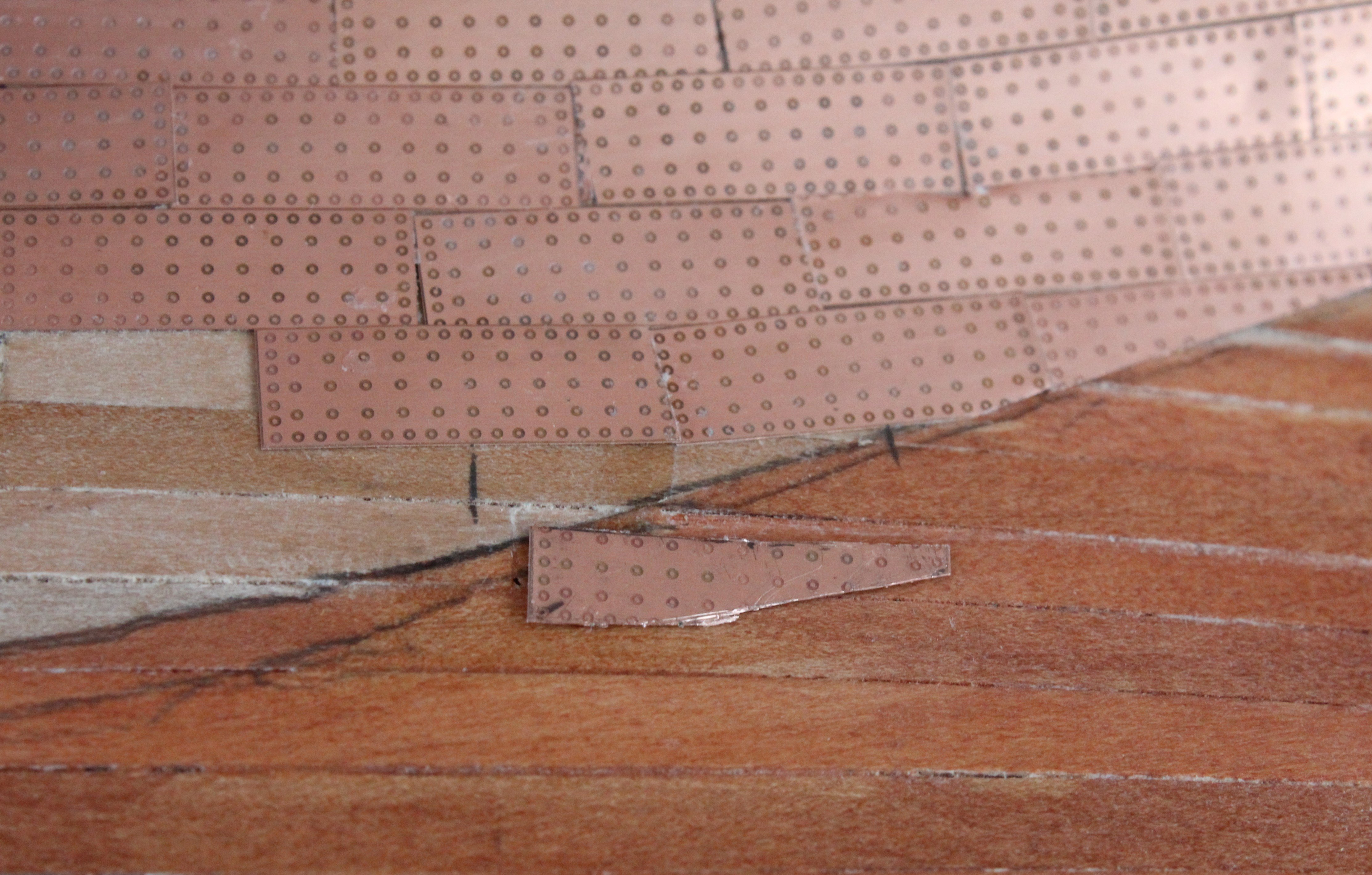
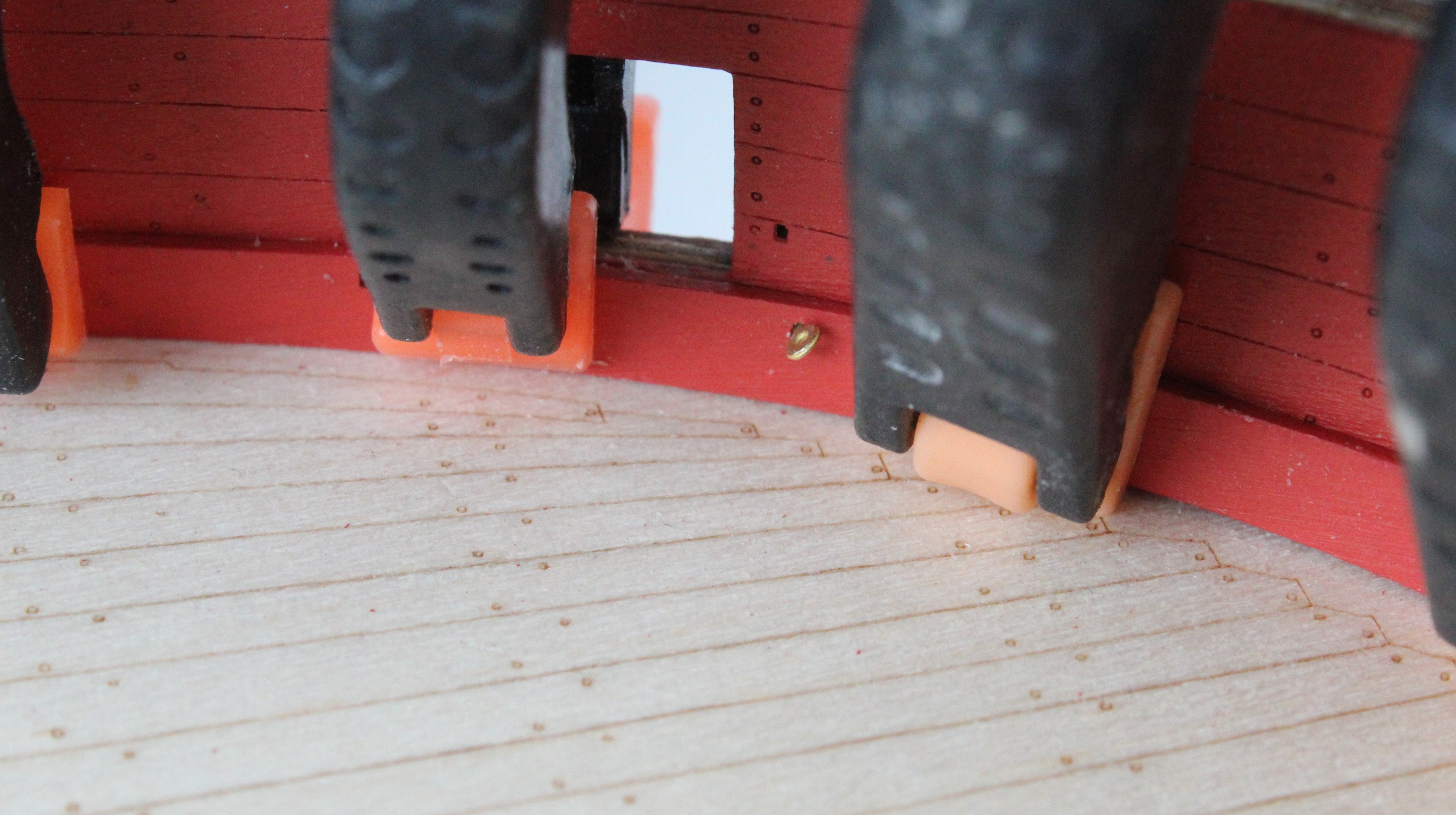
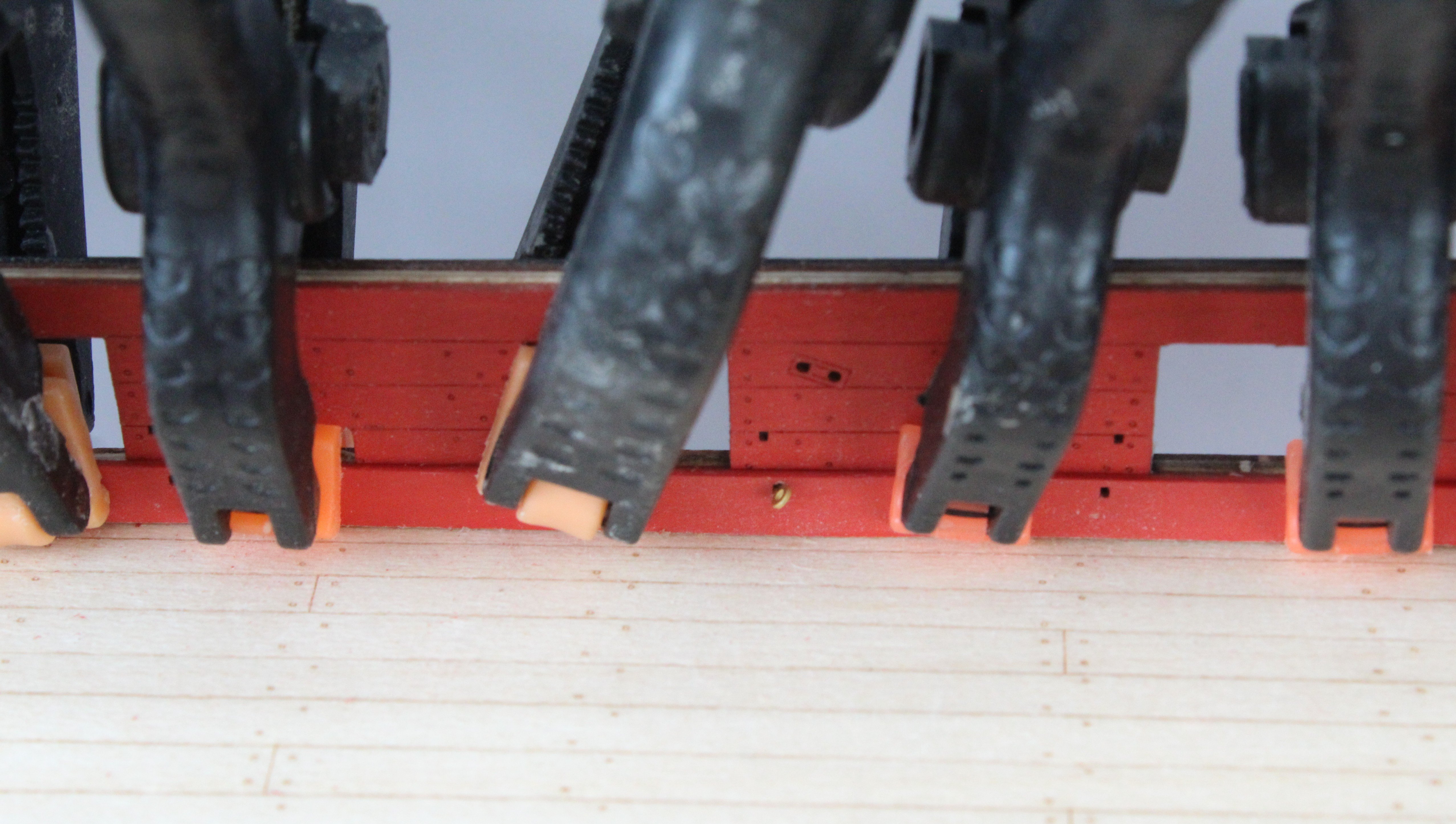
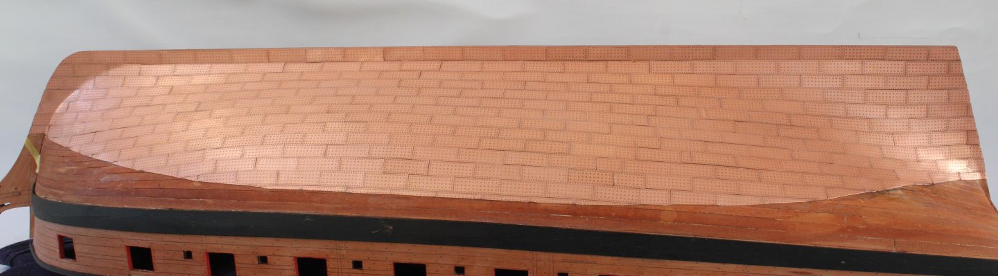
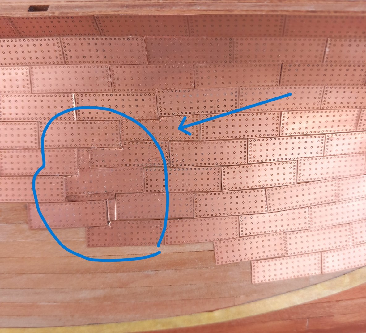
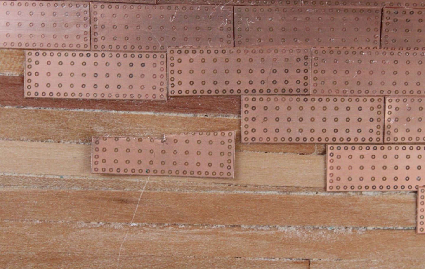
Copper plating the second side of the Harpy has been progressing well, in between my wife's post operative hospital visits, and I reached a stage where there was only 1 or 2 more days work left to complete, as can be seen below. However I have hit major a problem in that the copper plates, when glued in place are simply not adhering to the hull. I have tried a few different things to try to overcome this problem without any luck. The problem is definitely with the surface of the bow section of the hull which is not allowing the ca glue to react, adhere and cure. Clearly I need to resolve this issue but I have no idea what to do for the best as I have already tried several things, such as: a) adding a new WOP coat. b) adding a paint layer c) sanding d) brushing water on hull As can be seen below I have had several failed attempts at adding more copper plates to the hull. Unless I can find a solution I feel I might have to resort to painting the lower section of the hull. This will mean I will have to remove all the copper plates. At the moment I feel this will be lesser of the two evils.


- 241 replies
-
- 1
-
-
- Vanguarrd Models
- Harpy
- (and 1 more)
-
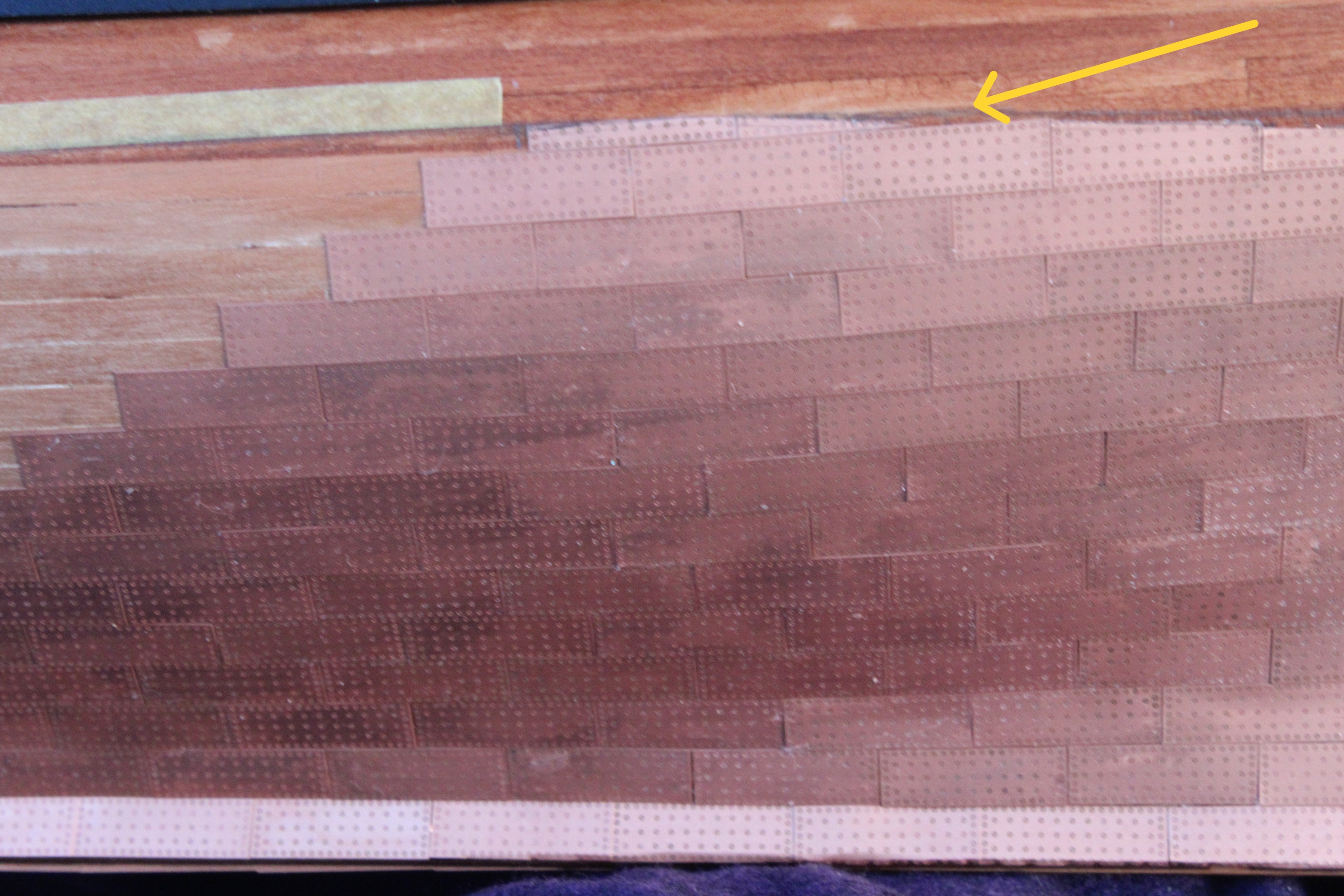
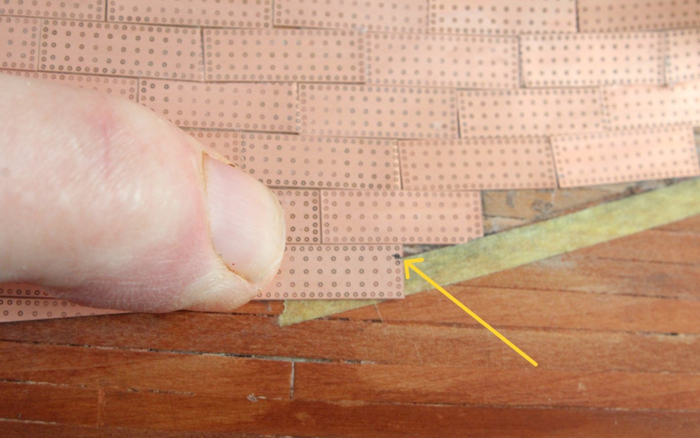
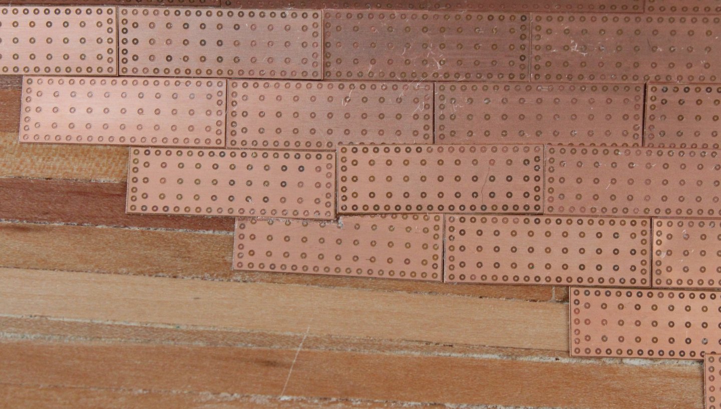
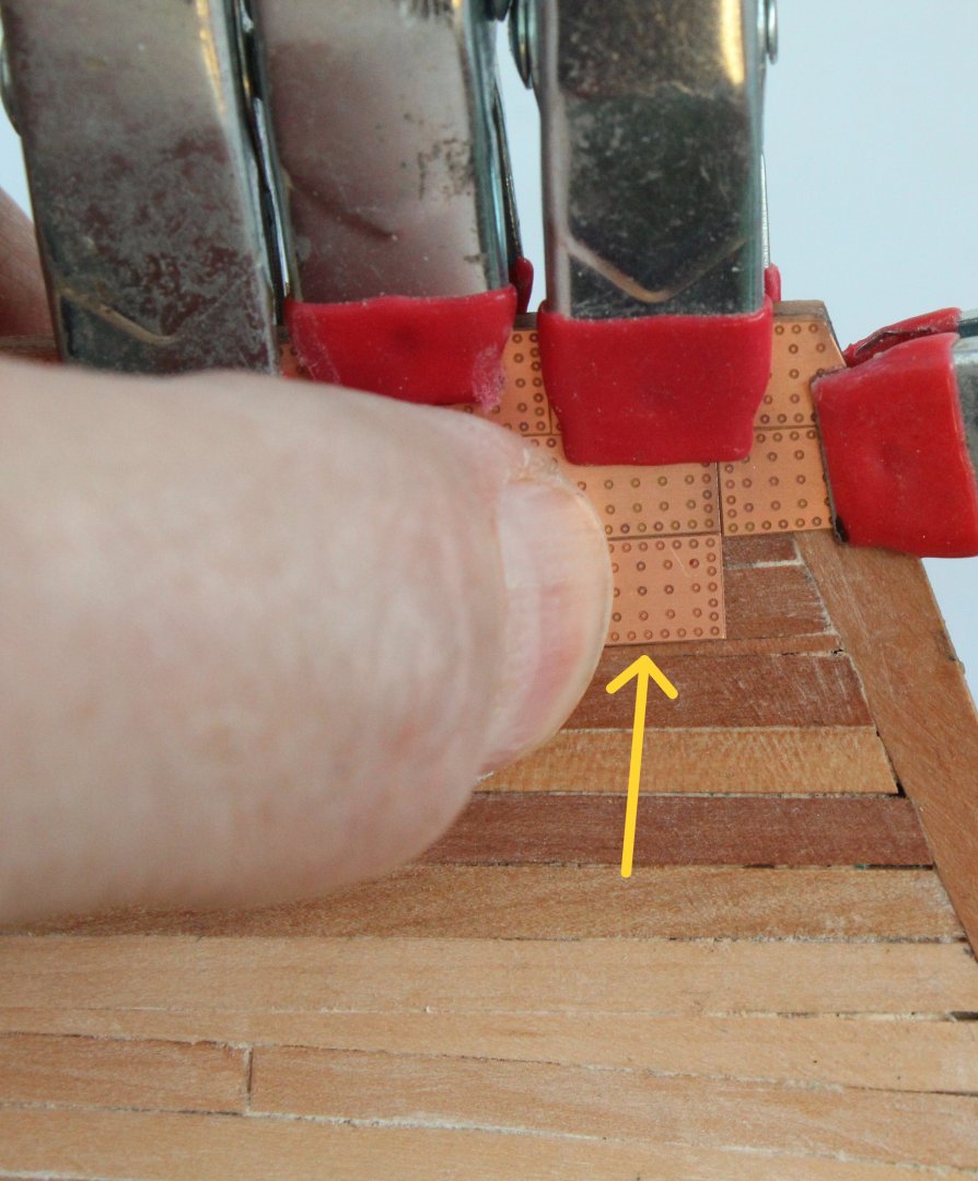
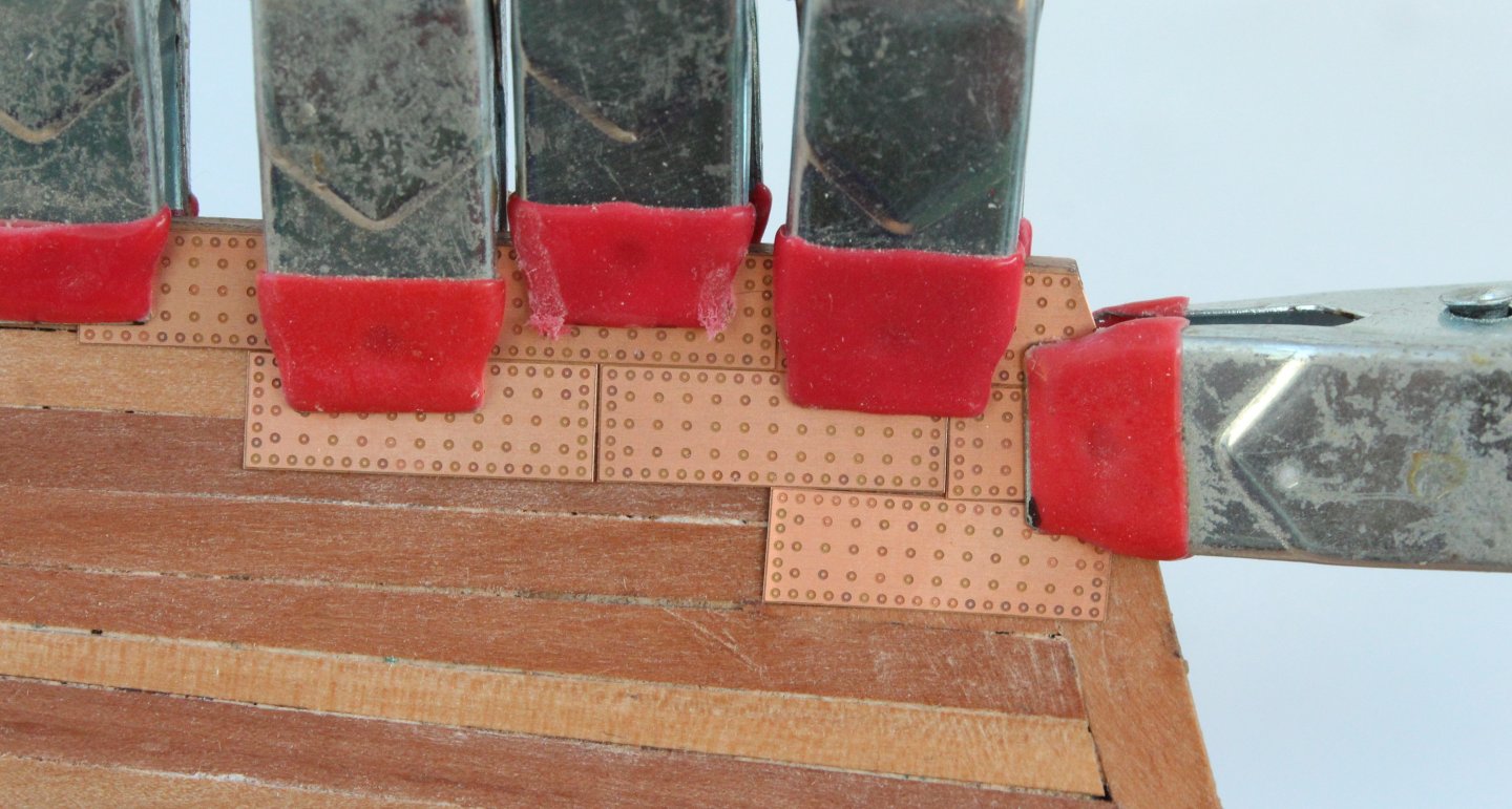
Copper plating the other side of the hull continues, I have made reasonably good progress today and feel the end is in sight in the next few days. I will be adding a 1mm square batten to neaten up the copper plating along the waterline. For the most part I have made a better job of this side of the hull. I will need to redo the copper plates fitted up to the waterline, as can be seen in the photo below. The copper plates will be buffed cleaned. I will need to revisit on small area, as indicated by the yellow arrow as for some unknown reason I had a senior moment. I also need to replace the upper most right hand copper plate .


- 241 replies
-
- 8
-
-
- Vanguarrd Models
- Harpy
- (and 1 more)
-
Thanks Mark
-
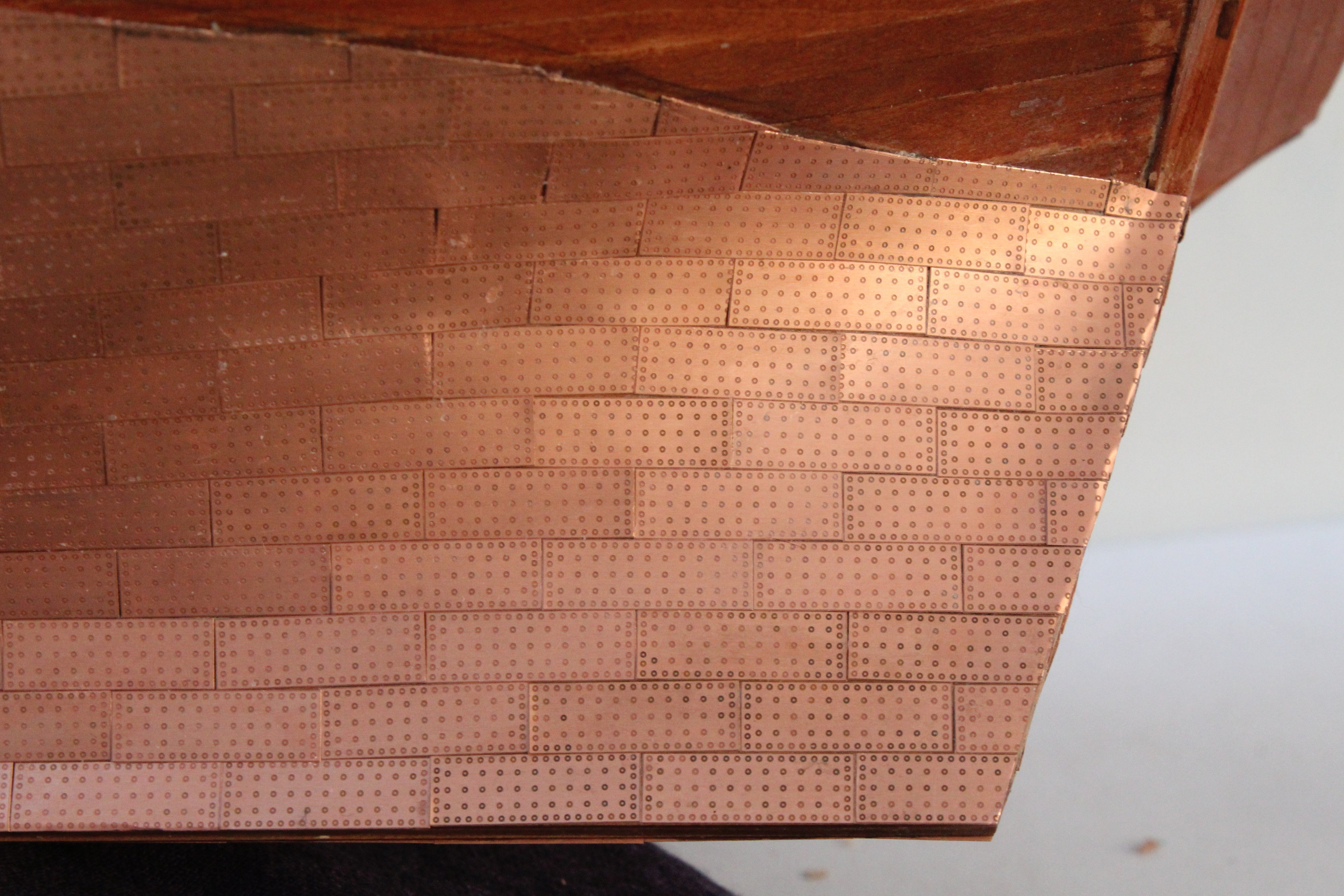
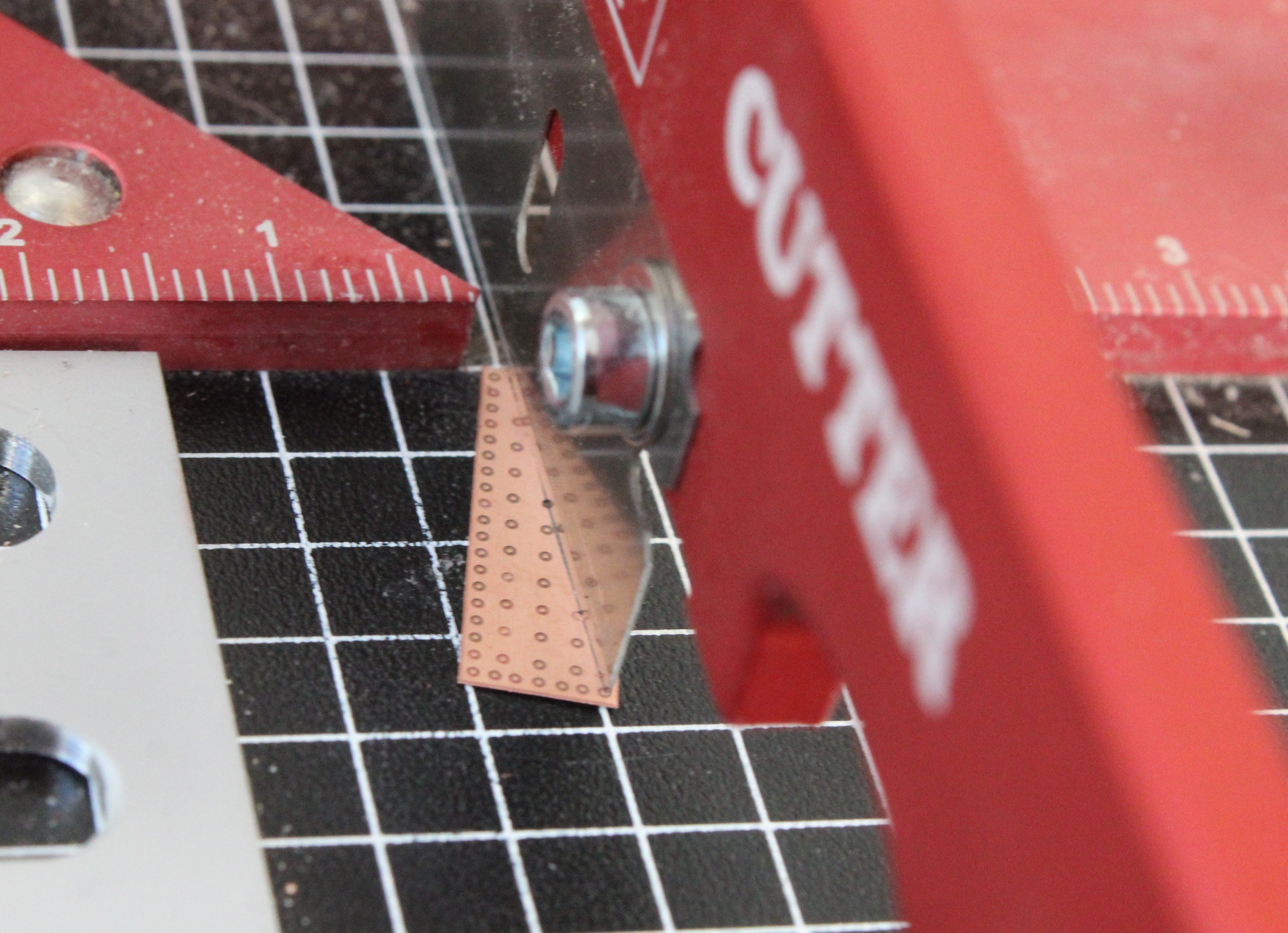
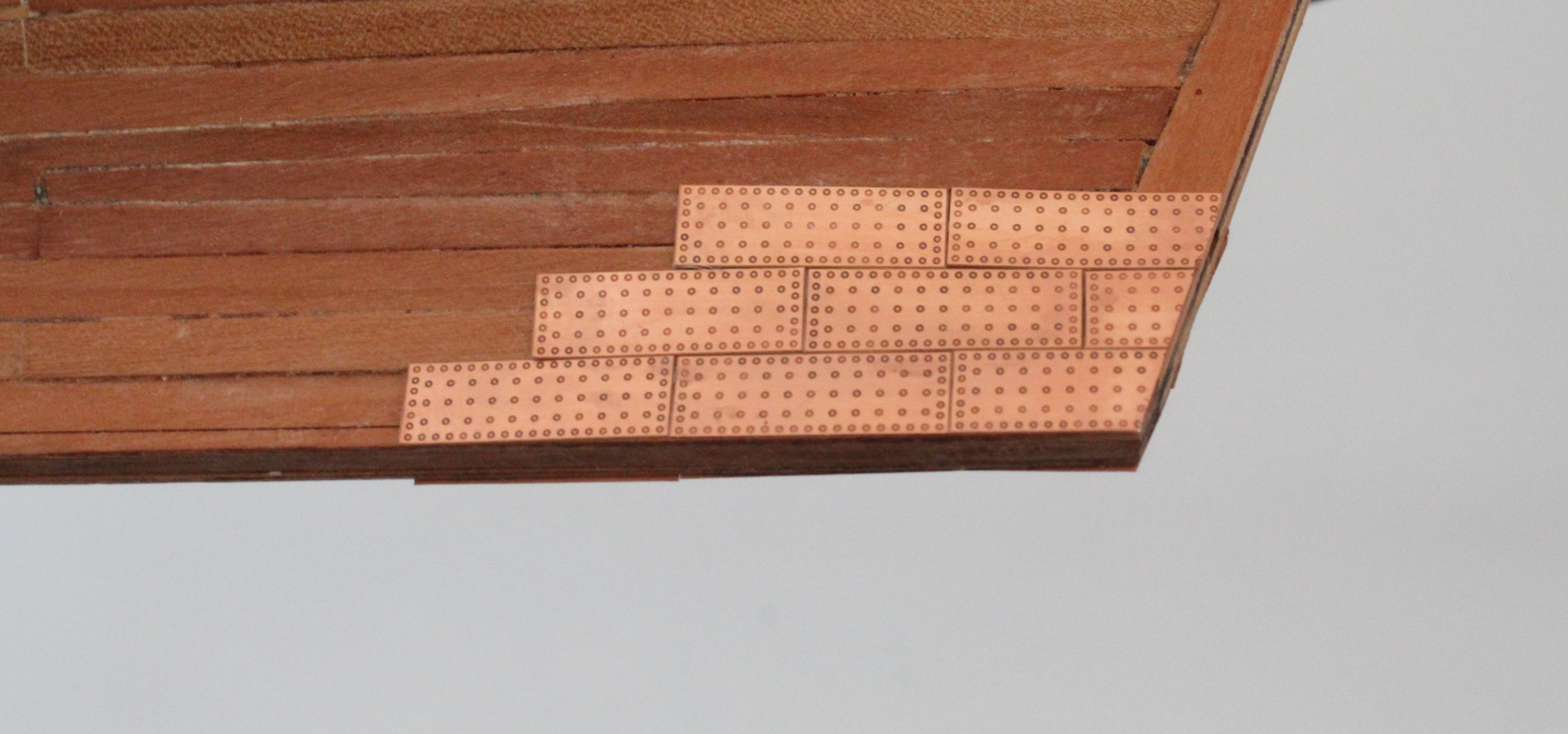
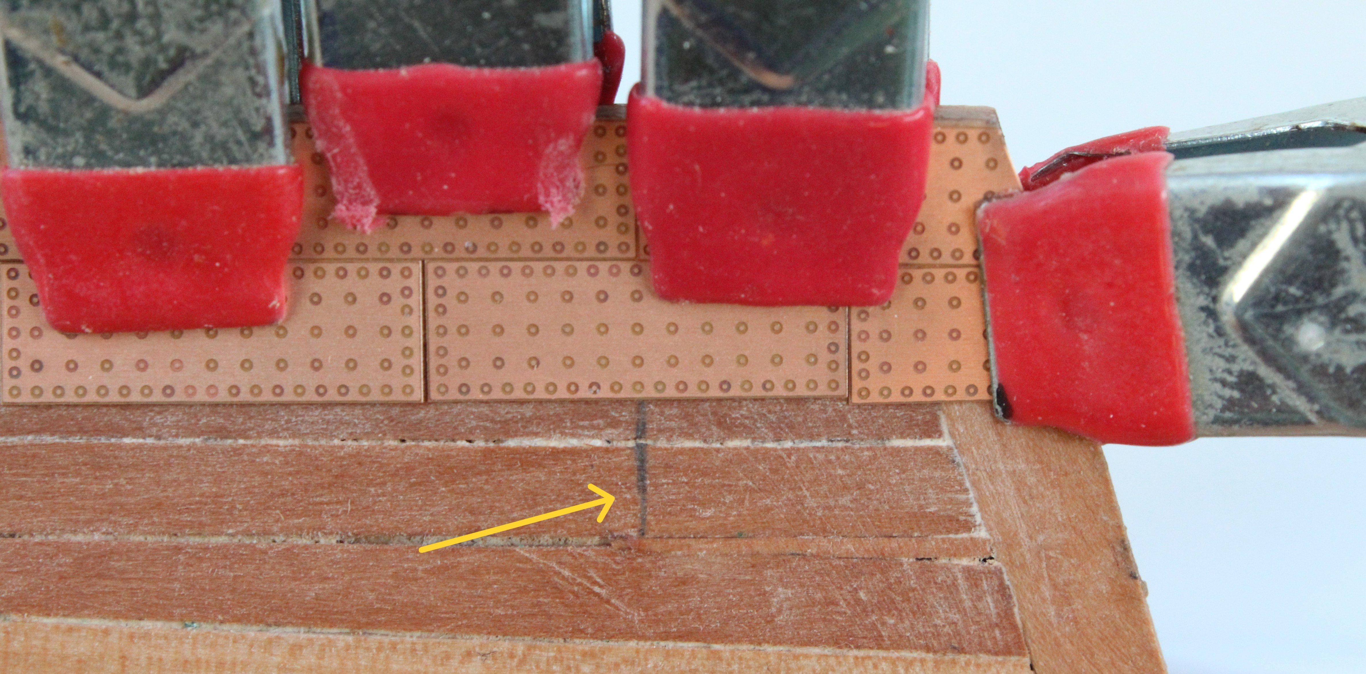
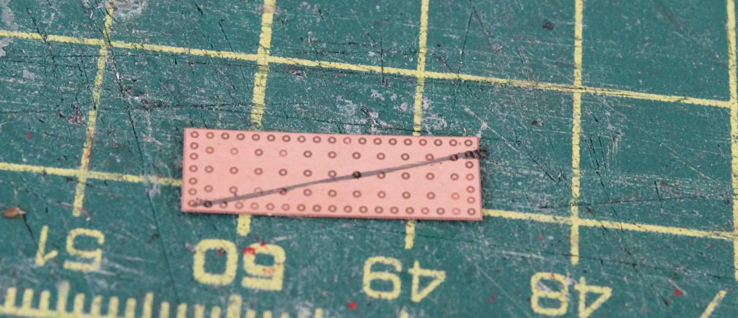
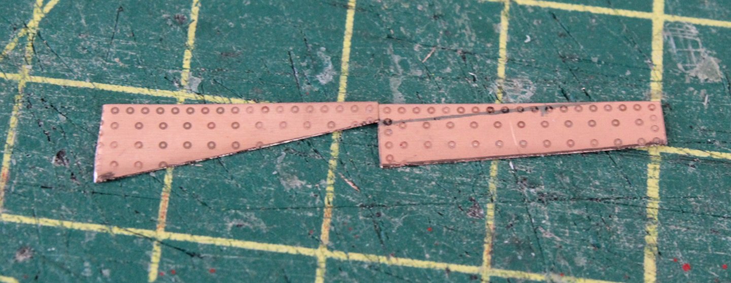
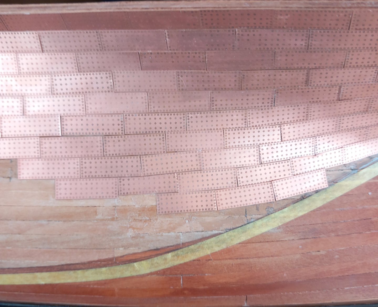
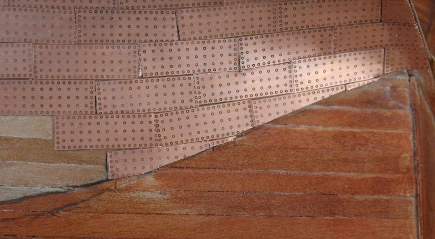
Today I completed the copper plating on one side of the hull. I will add a 1mm square batten along the top of the cooper plates to neaten of the edges. I did a test fit of the rudder assembly. I will need to trim the rudder copper plate sheet to match the hull lines. The following is an insight in to how I went about fitting the copper plates along the water line. A copper plate is offered up to the hull and the pencil mark is made where it meets the waterline. Next I draw a line between the pencil marks. The copper plate is then cut to size, using my guillotine. The next copper plate is marked up and test fitted against its adjacent copper plate. When I am happy with how they look they are glued in place.


- 241 replies
-
- 13
-
-
- Vanguarrd Models
- Harpy
- (and 1 more)
-
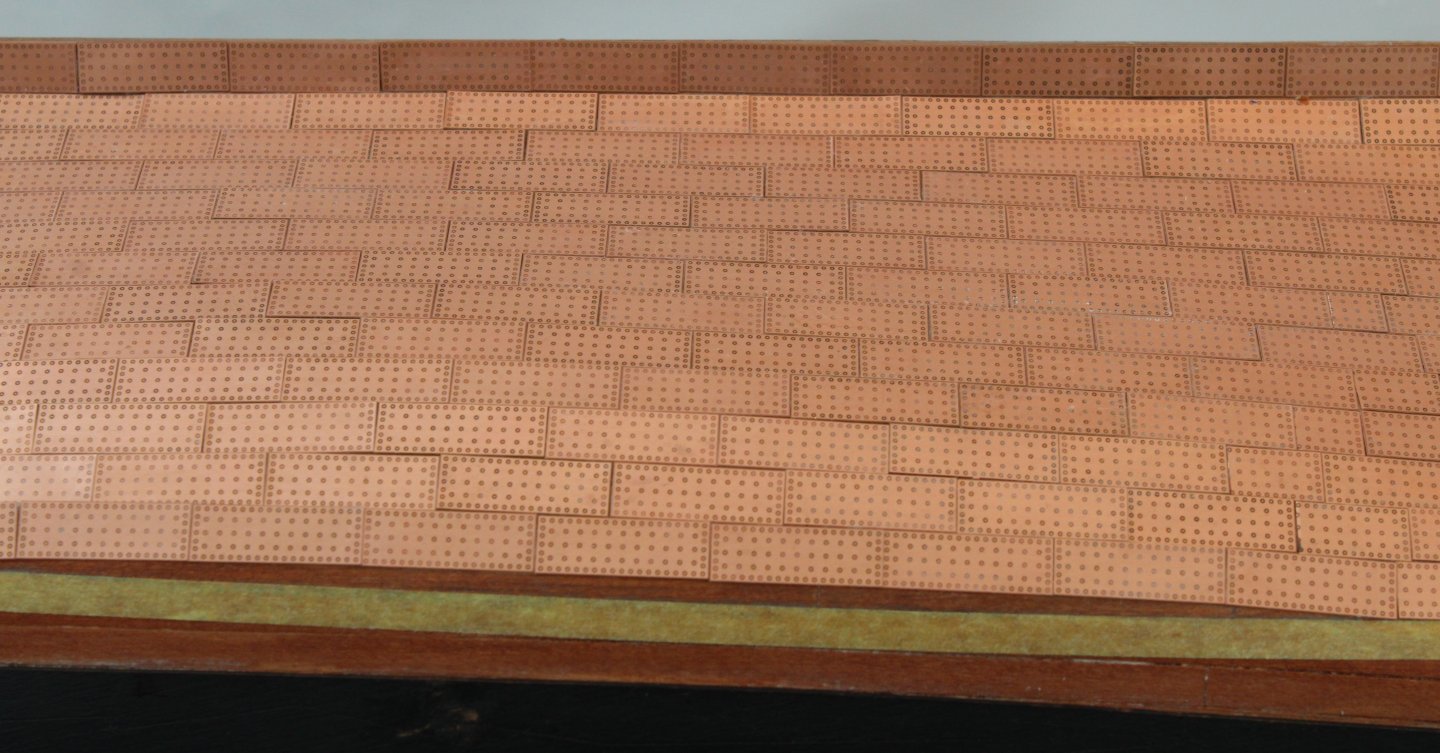
More progress on the copper plating task. I just have to add the infill plates up to the waterline on the first side, as can be seen in the photos attached below. Once that is done I will repeat the plating process (and hopefully I will make a slightly better job) on the other side of the hull. I am using cotton buds, dipped in acetone, to clean the copper plates once they are been positioned. Thankfully there is no sign of any ca glue of the plates that have been fitted so far.


- 241 replies
-
- 11
-
-
- Vanguarrd Models
- Harpy
- (and 1 more)
-
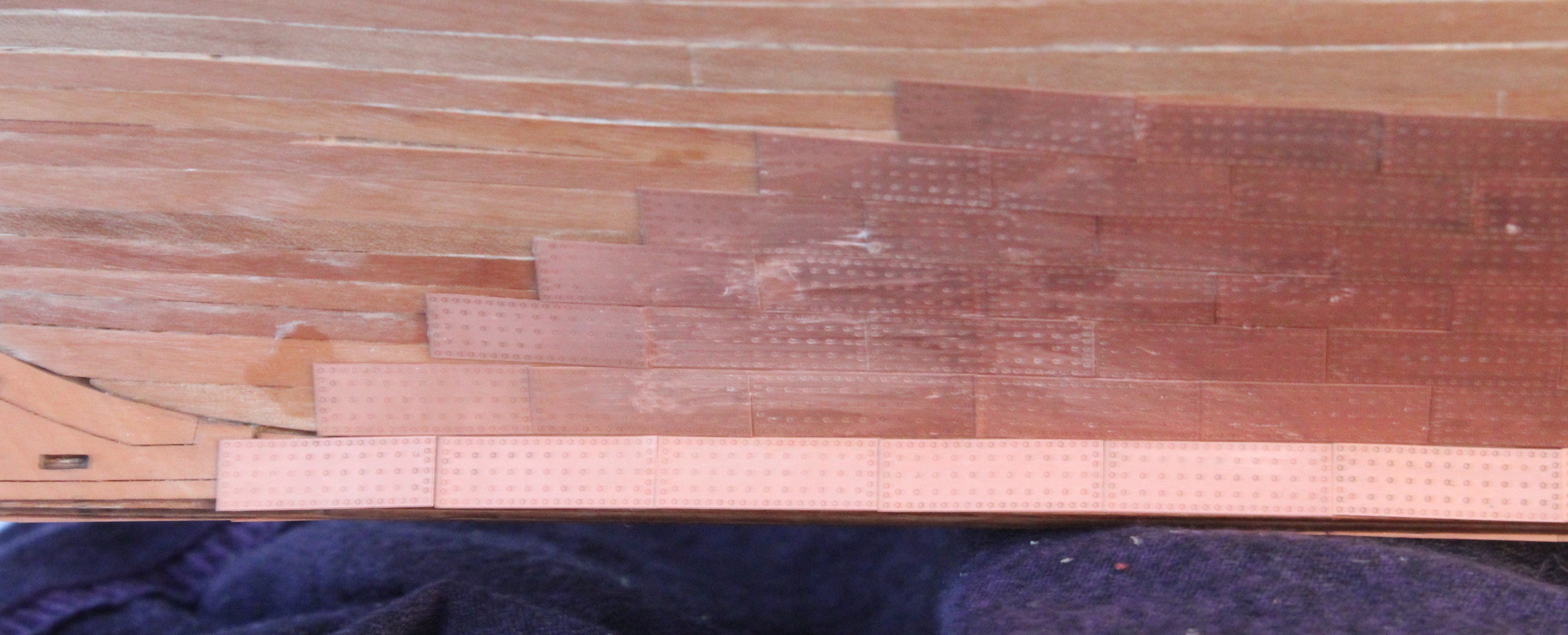
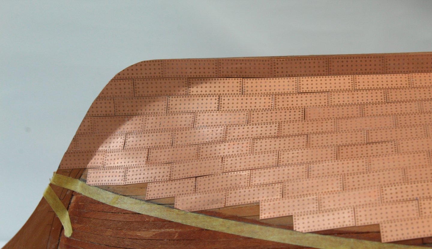
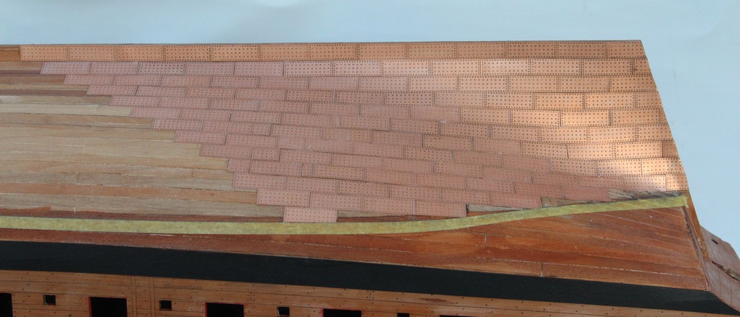
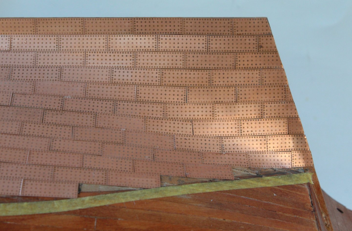
Dropped my wife off at the hospital this morning, we were told she was last on the list and I was not permitted to stay with her. This meant I was free to return to the shipyard. I think my mind must have been elsewhere when I decided to be clever with shaping the copper plates and ended up making a right mess. I ended up ripping off many of the plates and redoing again. Looks a bit better second time around. Using the copper plate pick-up tool it is a relatively quick and easy task to fit each plate. The hard work will be when I have to shape the plates along the waterline, which will be my last task. My coppering skills are not great but they look alright to my naked eye. I am making some minor adjustments, when necessary, so each layer is offset by half a plate width.

- 241 replies
-
- 13
-
-
- Vanguarrd Models
- Harpy
- (and 1 more)
-
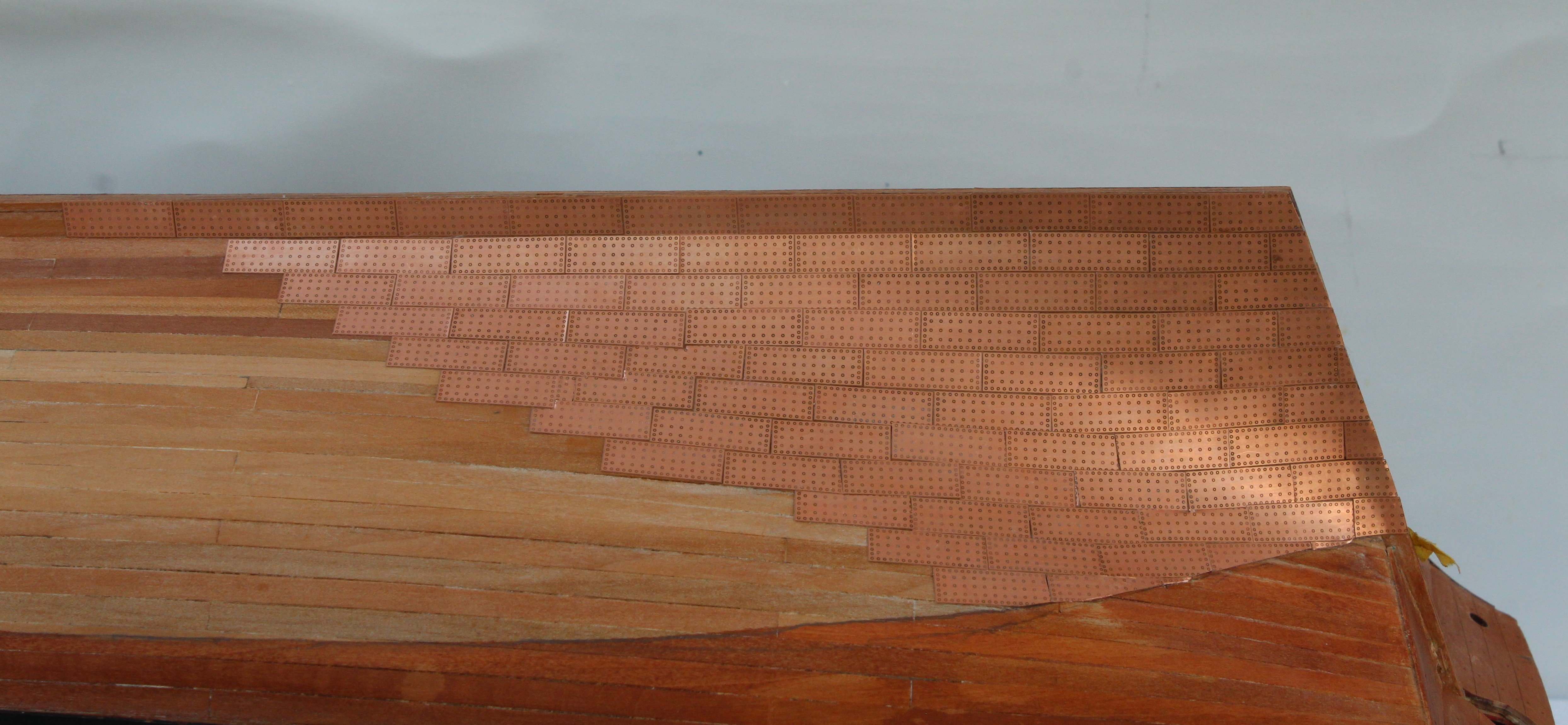
I have managed a couple of hours in the shipyard this morning. My first task was to copper plate the stern post areas up to the waterline. As the copper plating continues I sometimes need to shape the copper plates, as shown below. More shaping is required for the copper plates which follow the waterline. Progress is slow but steady. I am not sure when I will be able to get back in the shipyard. I might be able to sneak the odd few minutes during the week, but in all probability my next visit will sometime over the coming weekend or early next week. The following photo is the current build status.


- 241 replies
-
- 16
-
-
- Vanguarrd Models
- Harpy
- (and 1 more)
-
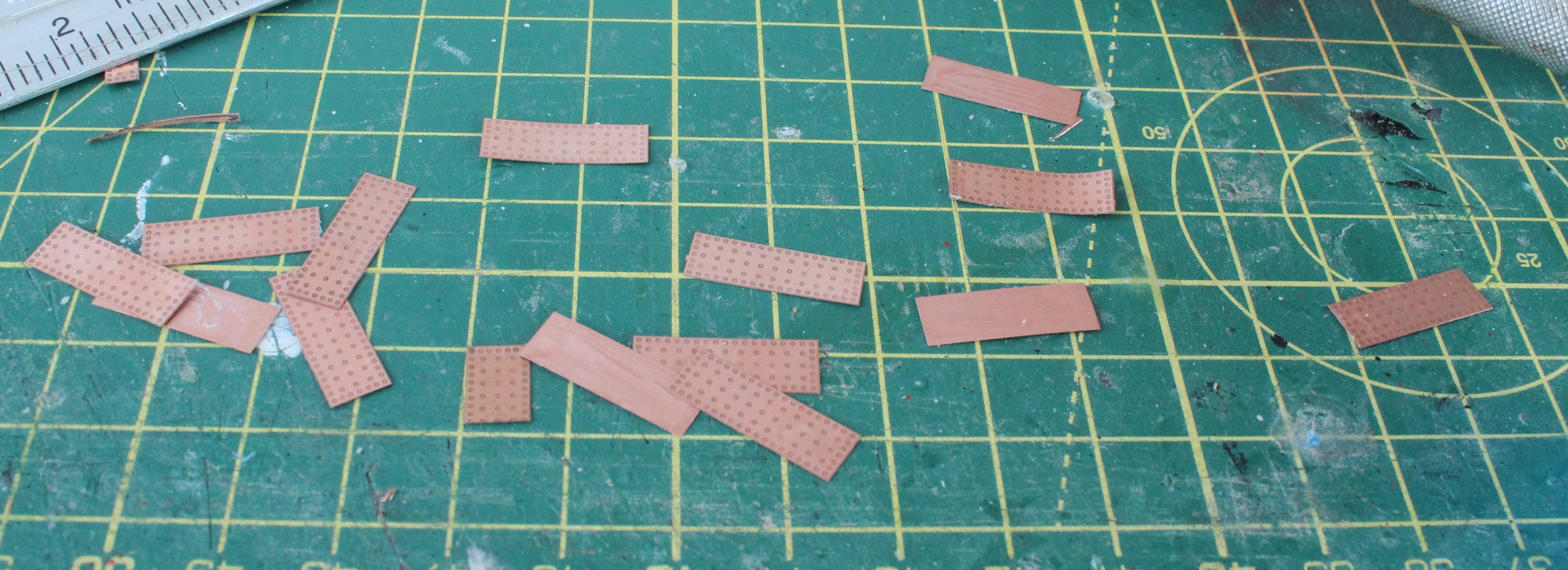
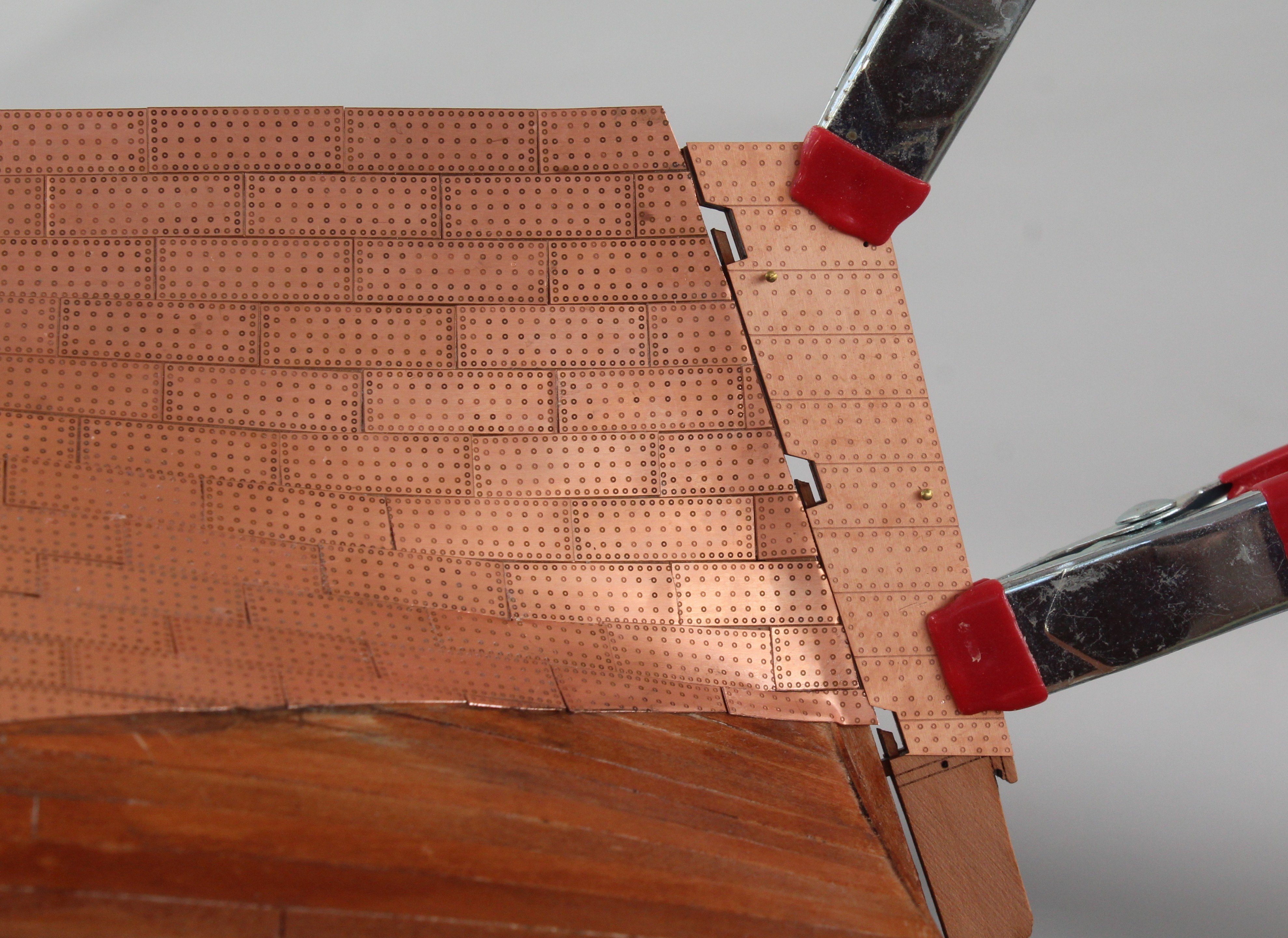
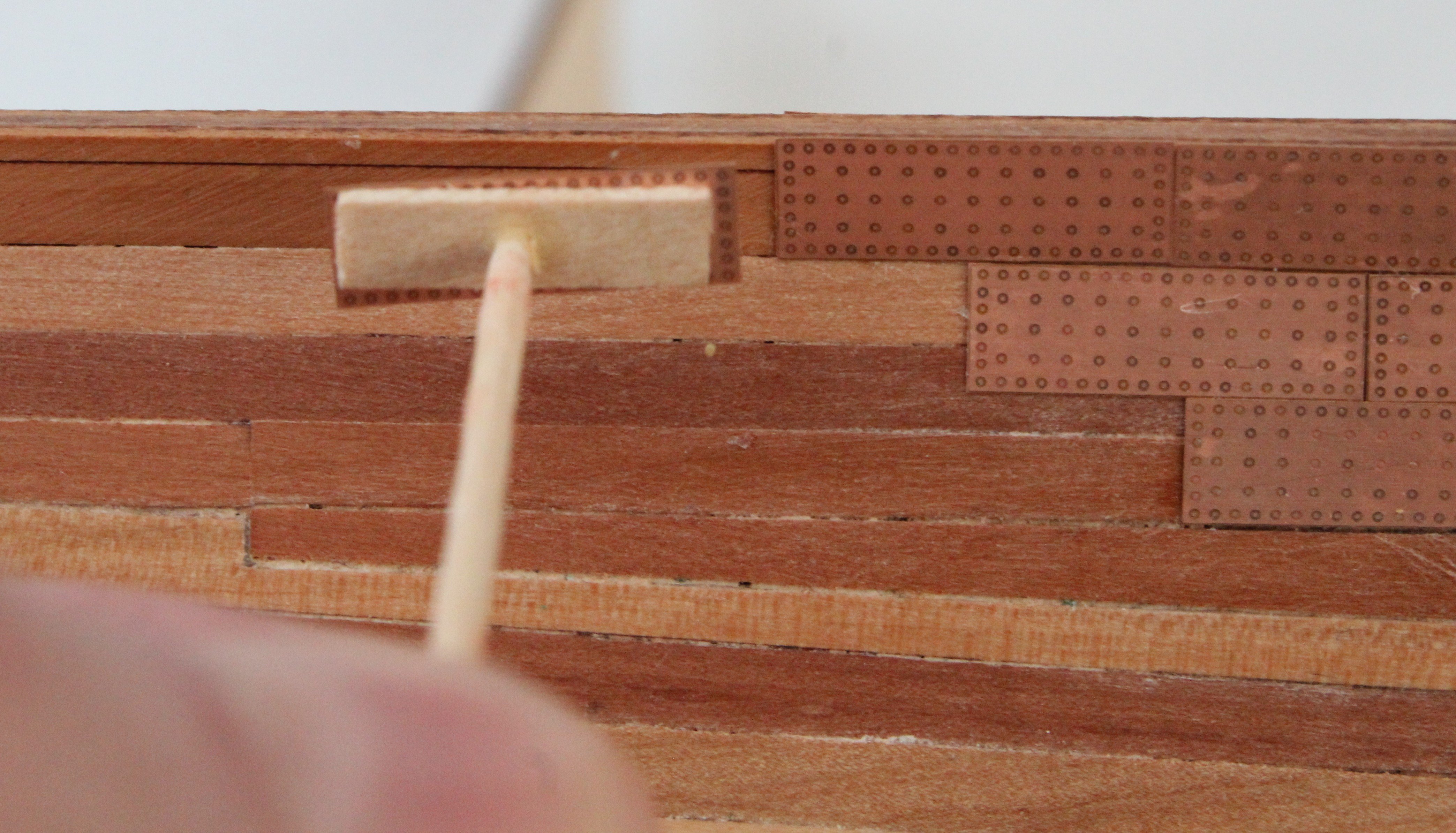
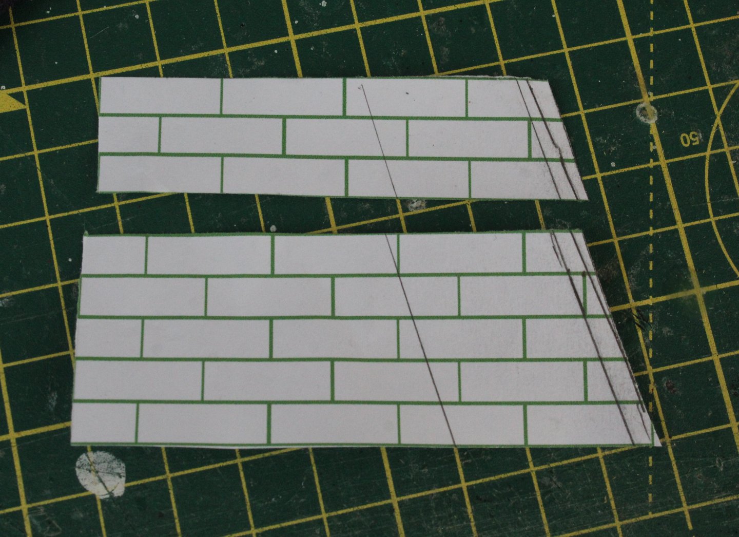
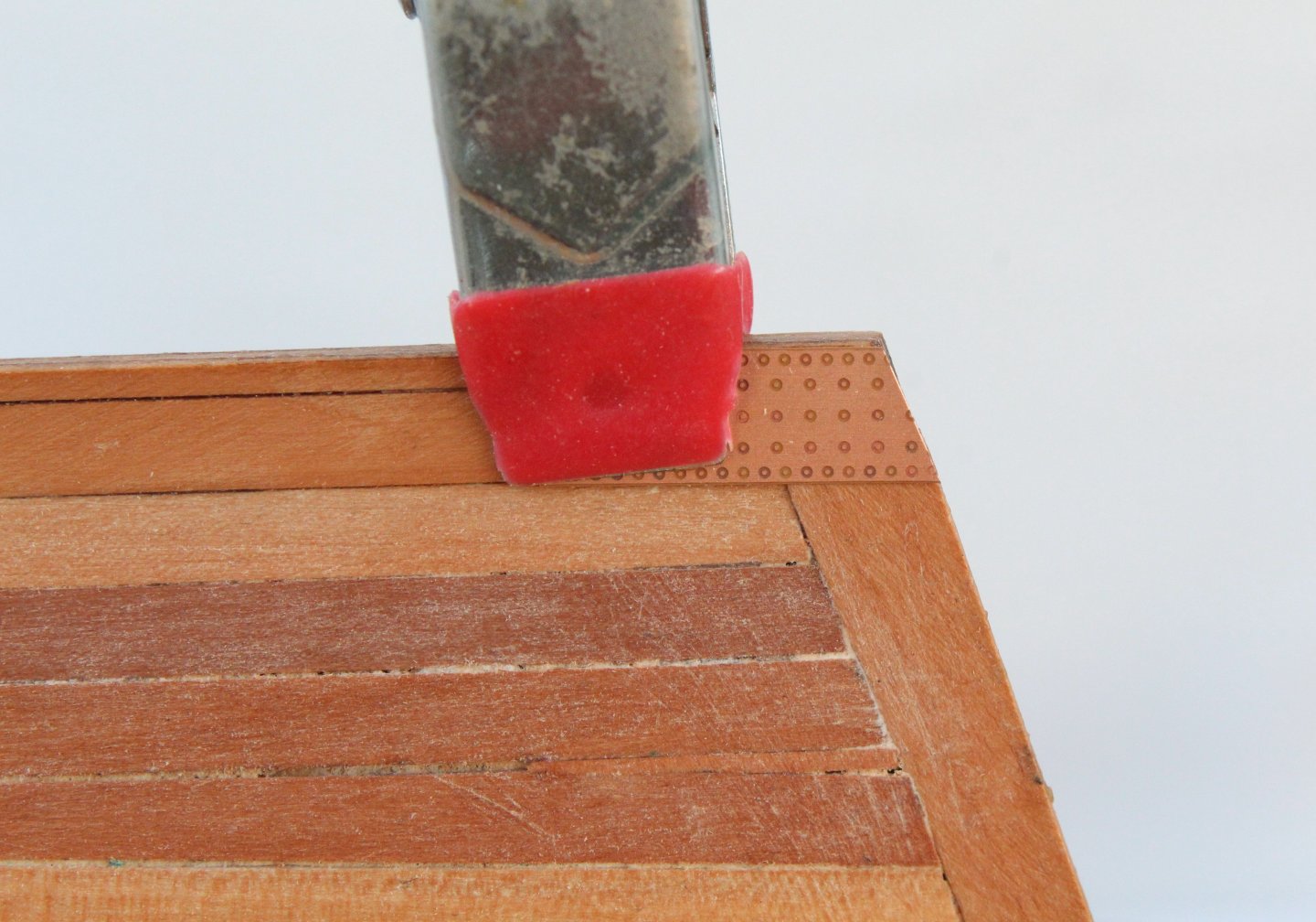
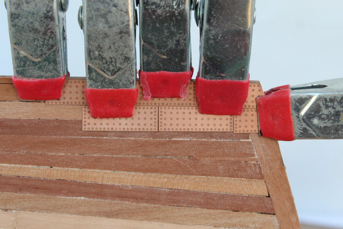
I managed a quick and unplanned 40 minute visit to the shipyard this afternoon and made a start with adding the copper plates. I started the process by printing out a plating template so that I could decide where to trim the stern post edge plates. As can be seen in the photo I covered the first 8 layers and I drew a few lines before deciding where to make the angles cut. The copper plate was then cut to shape using the template as a guide. After a few trial fits I was happy to proceed and as can be seen I have added a few copper plates to both sides. I am using the same method detailed by @Blue Ensign in his excellent Harpy build log and so far it is working very well. Using the pick-up tool each copper plate is picked up. Tackey wax is used to hold the copper plate to the tool, as can be seen in the photo below. Using a cocktail stick a thin layer of ca glue is spread evenly over the base of the copper plate and it is then placed on the hull. A cotton bud dipped in acetone is then used to clean the copper plate.


- 241 replies
-
- 11
-
-
- Vanguarrd Models
- Harpy
- (and 1 more)
-
Thanks Jim, it has been a shock after so many years being cancer free.
- 241 replies
-
- 4
-

-
-
- Vanguarrd Models
- Harpy
- (and 1 more)
-
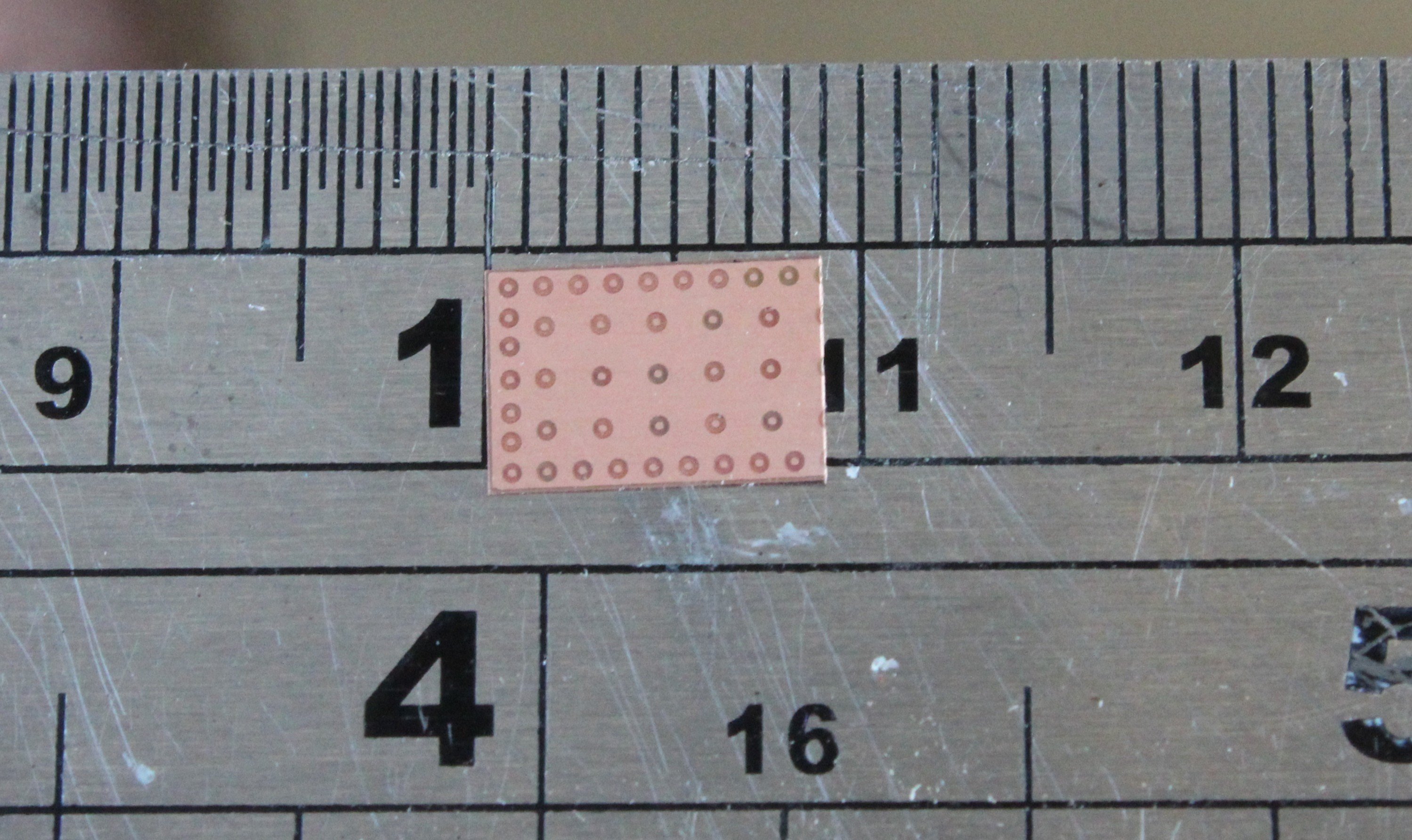
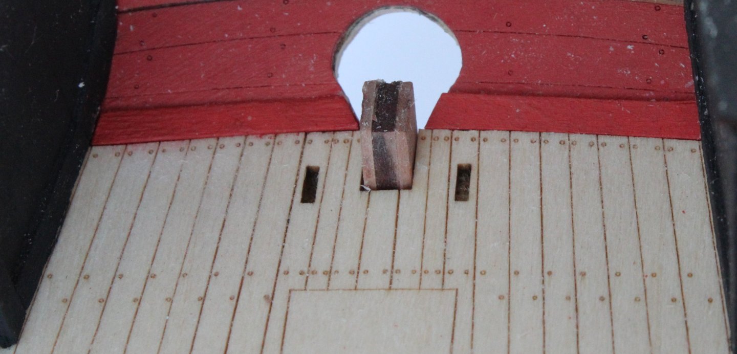
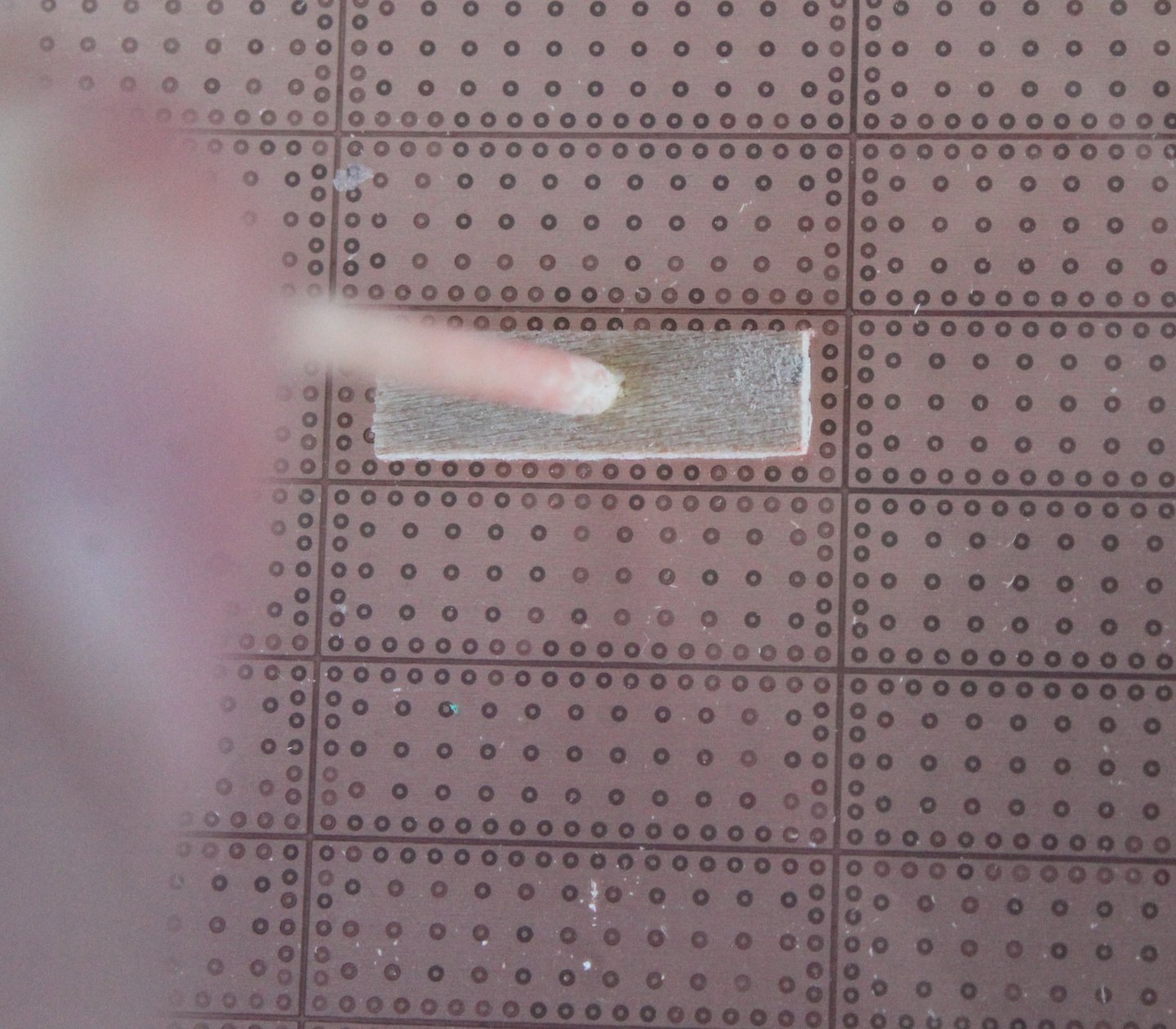
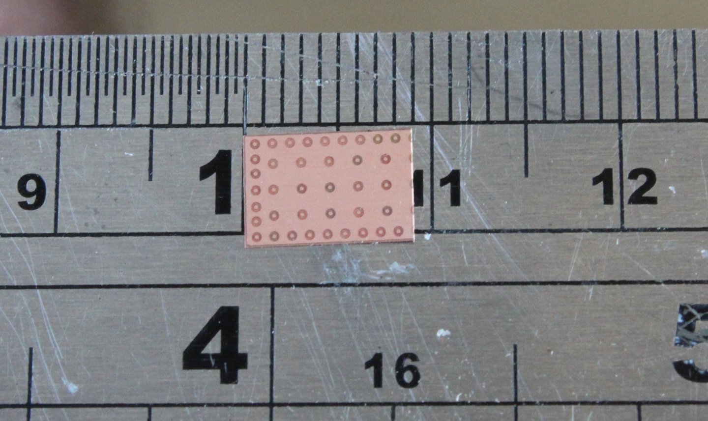
This may be my last post for a week or two. Tomorrow we have grandparent child care duties looking after a 3 year. Then we have family staying with us over the weekend which means spending more time entertaining some other grandkids (1 year and 4 year). Then on Monday we are looking after our youngest 1 year granddaughter for 4 days whilst her parents have a mini break in Venice. On a week on Friday my wife goes to hospital for an operation as her breast cancer has returned after a gap of 16 years. She is expected to make a full recovery after the operation but this will take a few weeks. I have not made much progress today as I am waiting for an Amazon delivery for tackey wax and some more ca glue. I have painted all the gun ports red. I have made and fitted the two margin planks between the deck and stern board. I am much happier with how this looks now. As I wait for the Amazon delivery I have done some prep work for the coppering of the hull. The first task was to make a tool for picking up and placing the copper plates. This is the same type of tool that @Blue Ensign used, i.e. a cocktail stick secured to a piece of planking material that is slightly smaller then the copper tile.. The tackey wax will be used with the tool to pick up and position the copper plates, when they to be glued in place.. Next I released all the copper plates (299 off) from the first copper sheet. I made a test fit of the first copper plate. I then tried test fitting a few more copper plates to get an idea of how the hull will look. Each copper plate is 18mmL so I cut 1 copper plate in half. The half tile is then used is mark the position the first tile in the next row, as shown with the sequence of photos below. The stern post edge plate can then be trimmed to suit as necessary.


- 241 replies
-
- 11
-
-
- Vanguarrd Models
- Harpy
- (and 1 more)
-
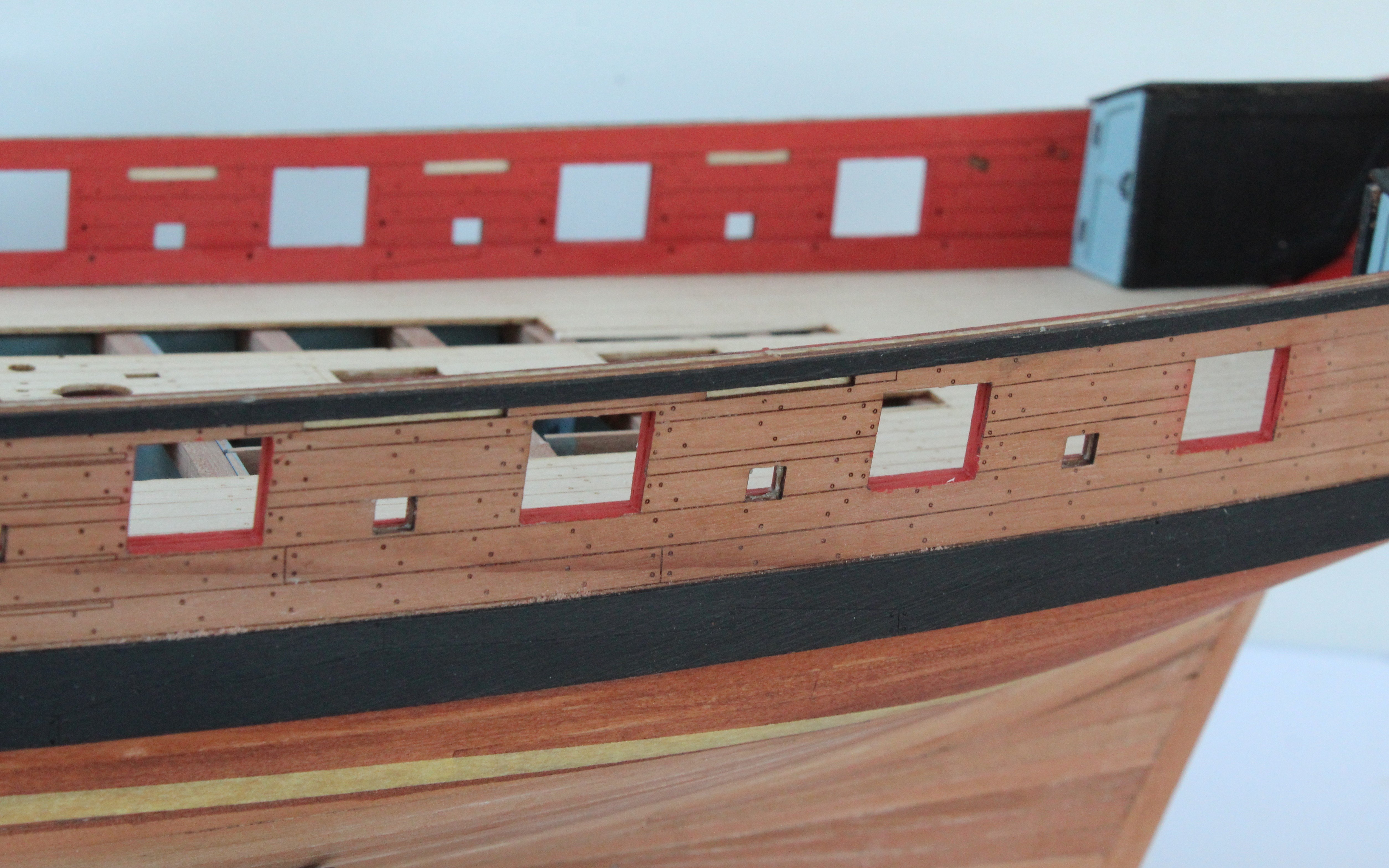
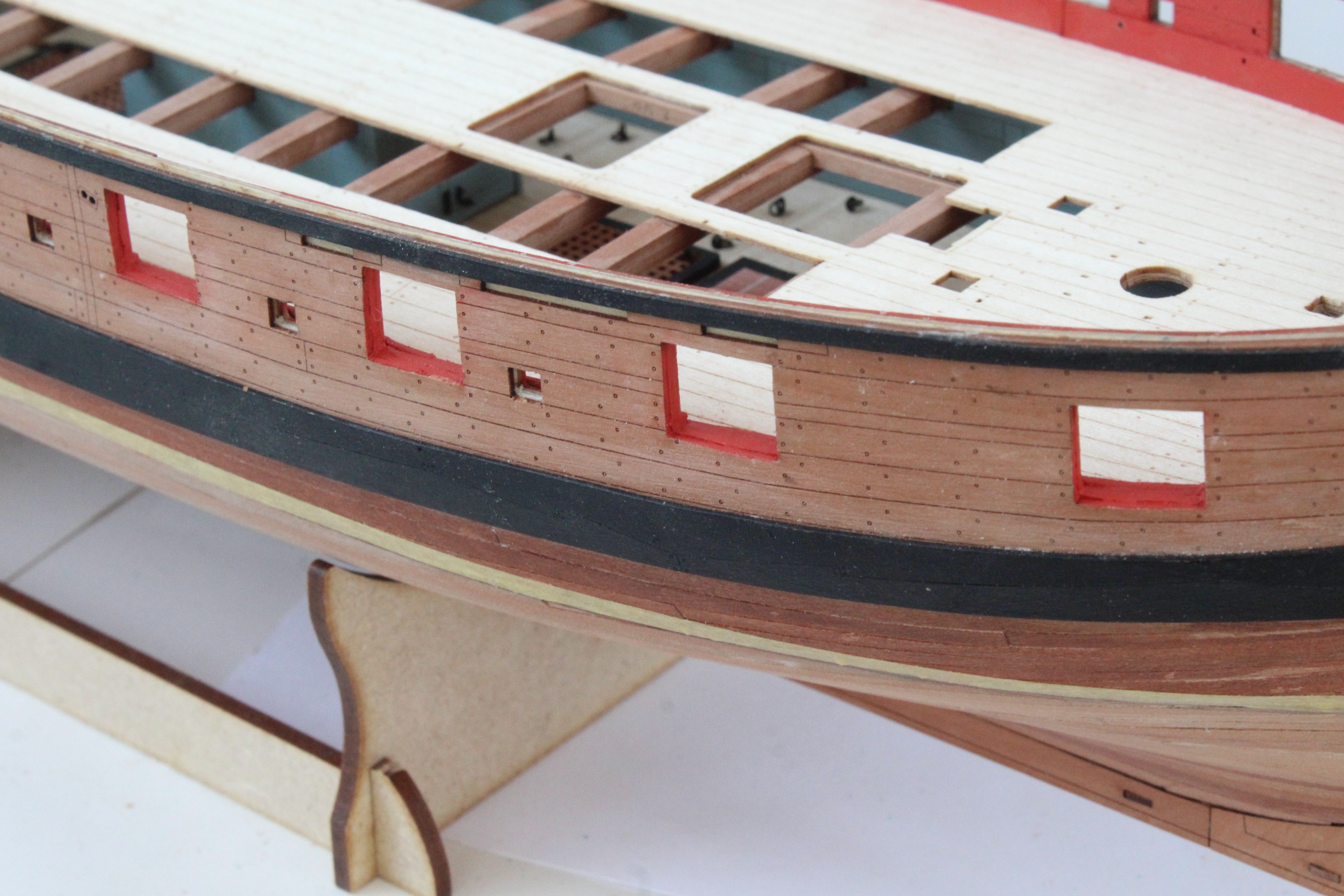
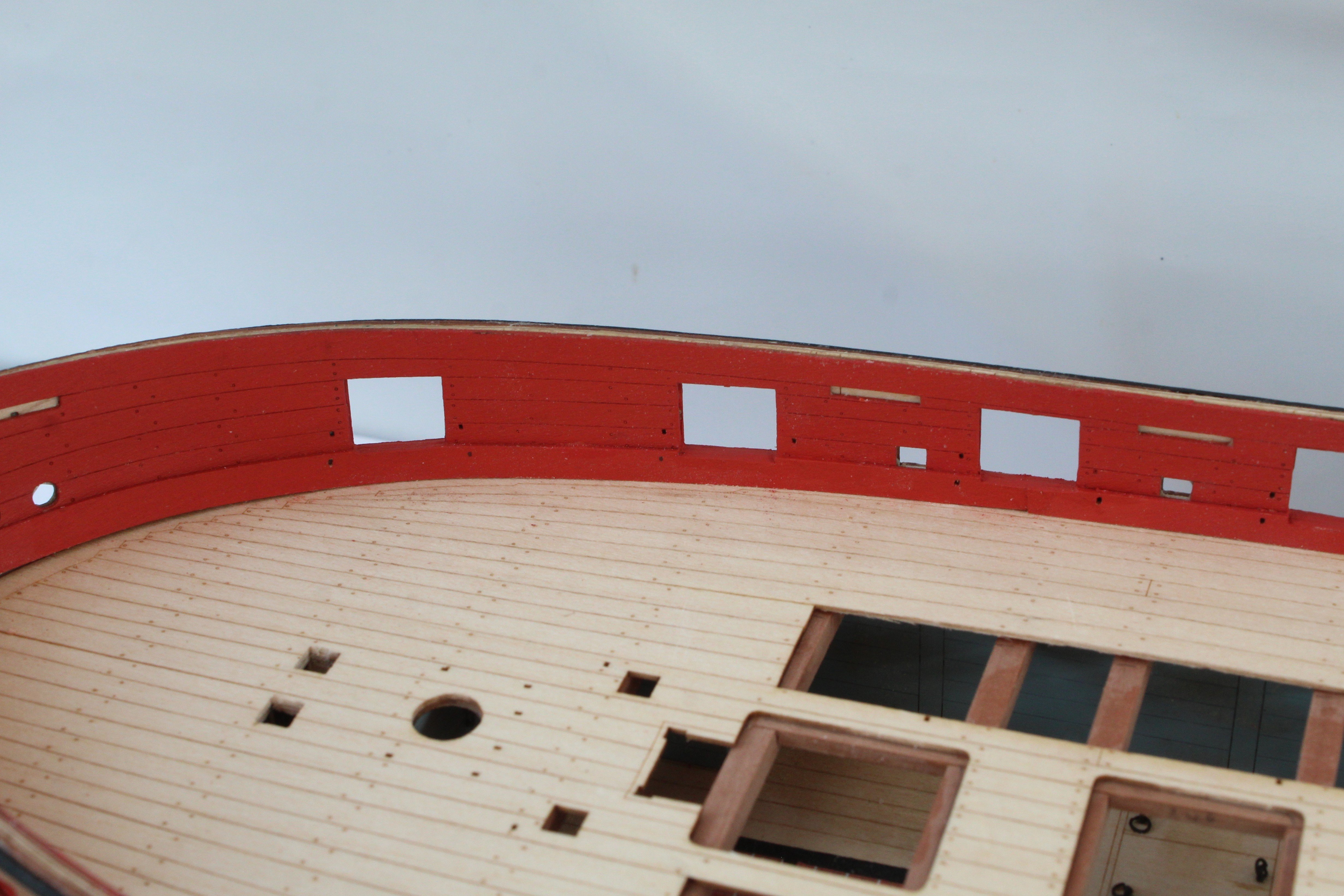
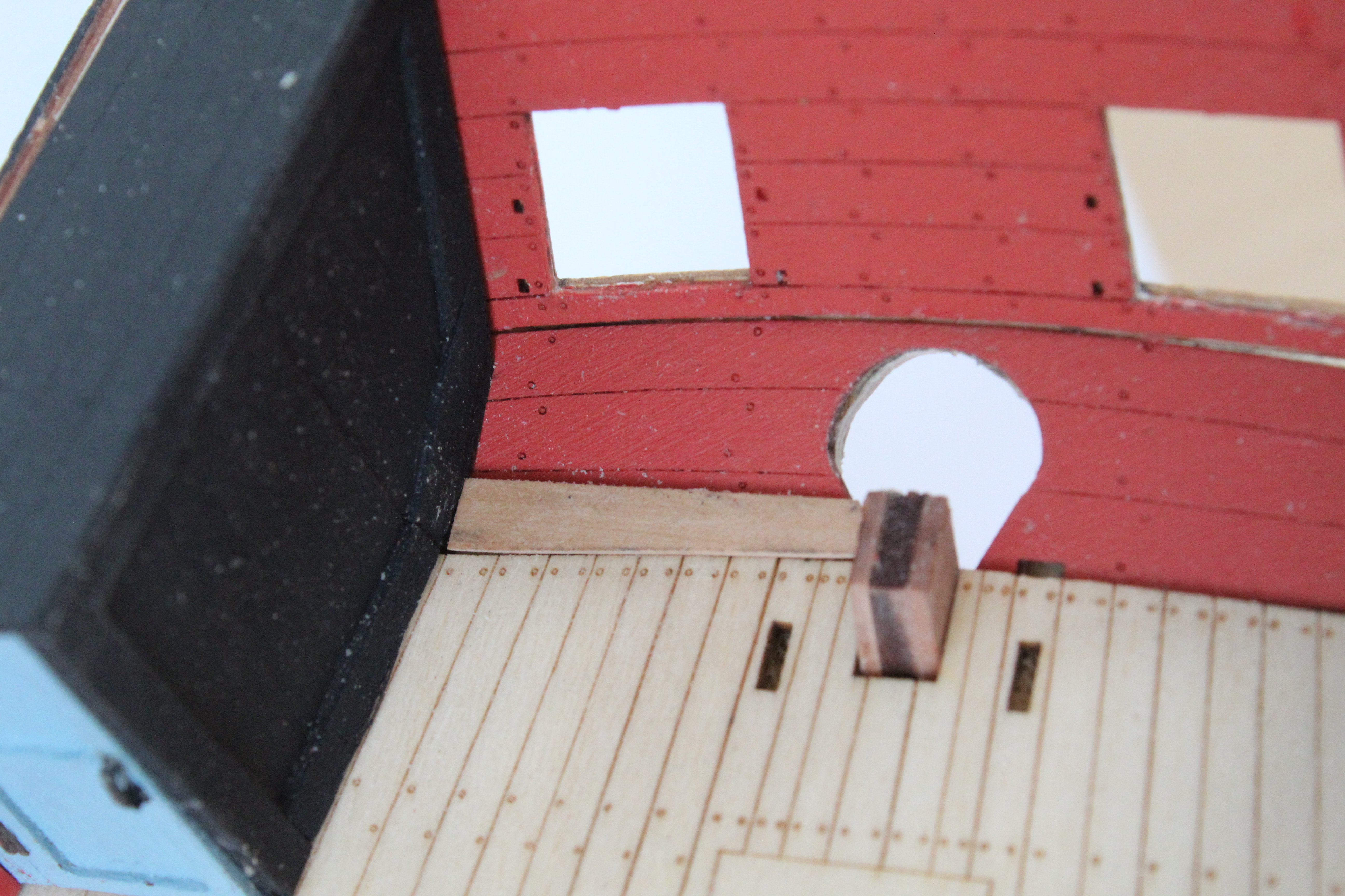
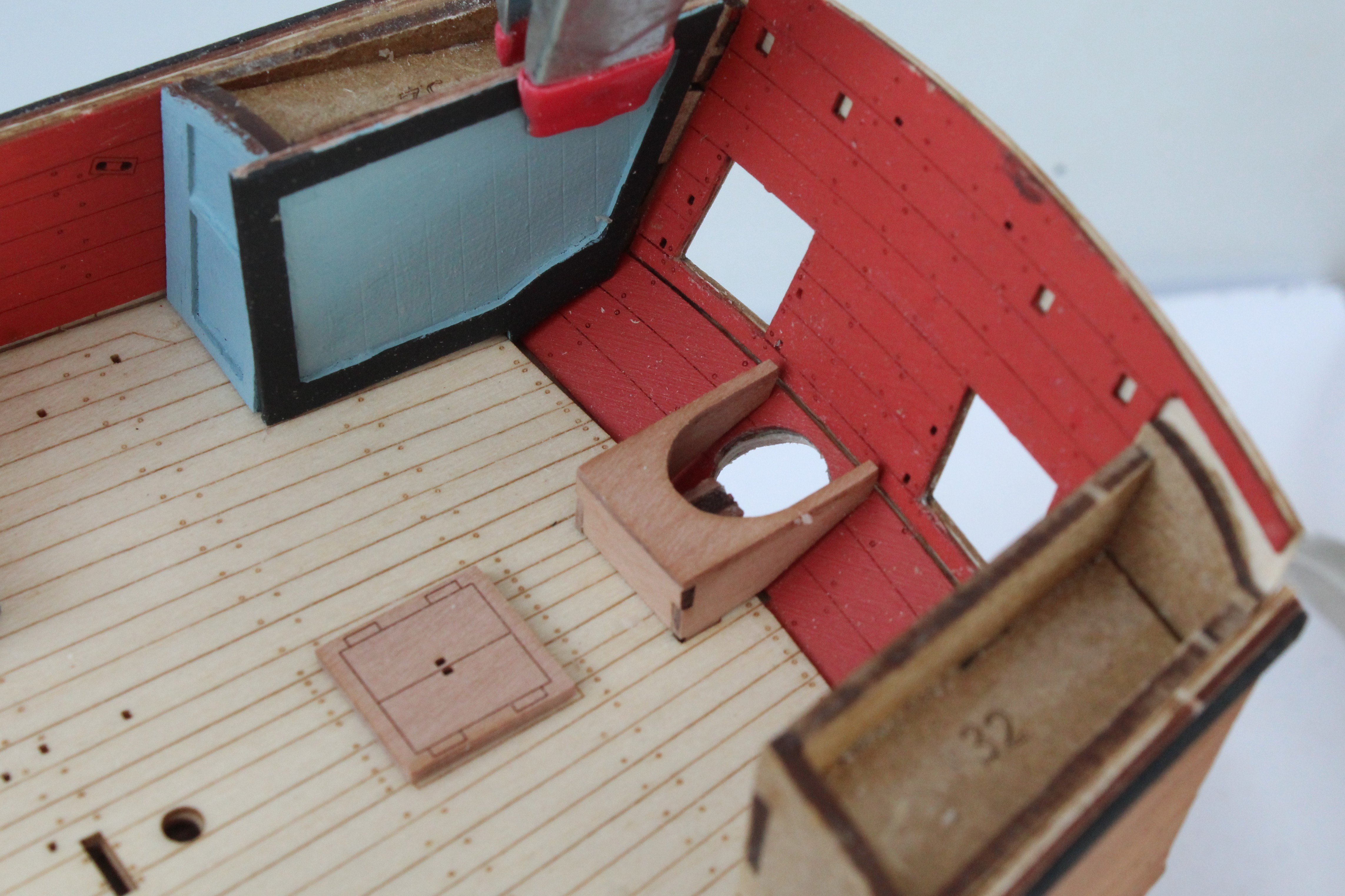
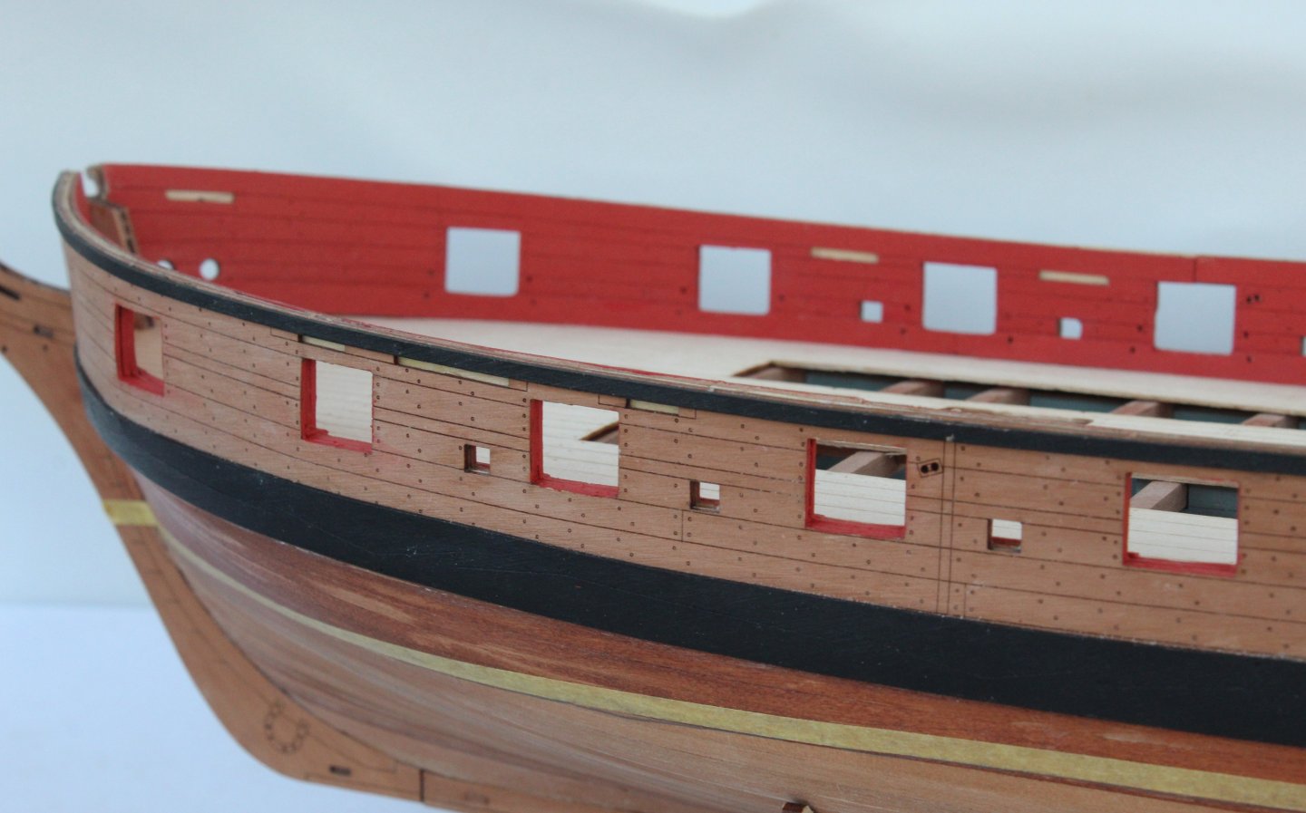
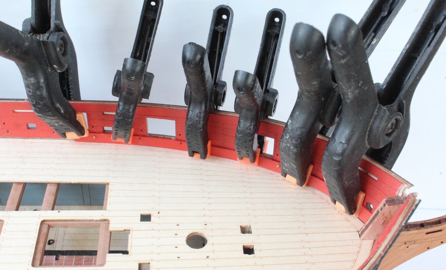
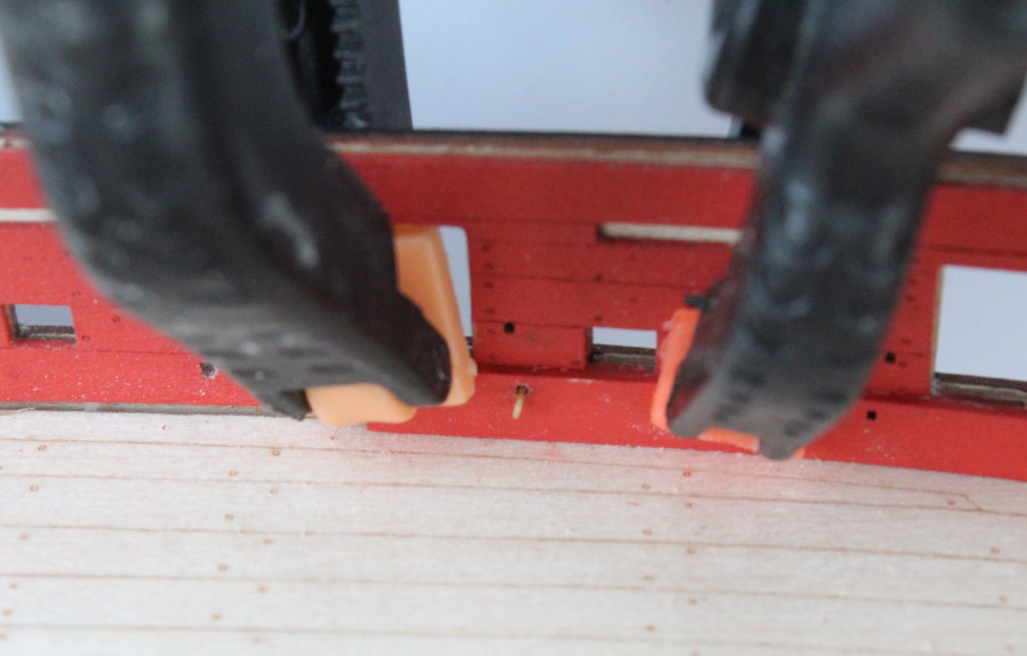
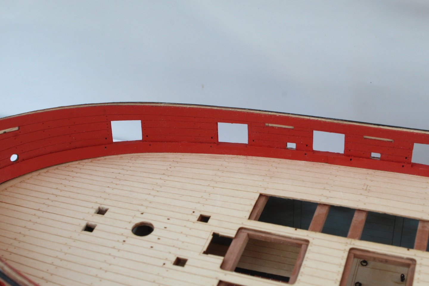
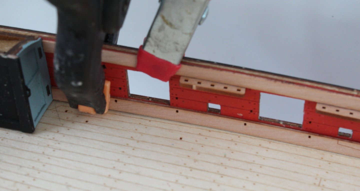
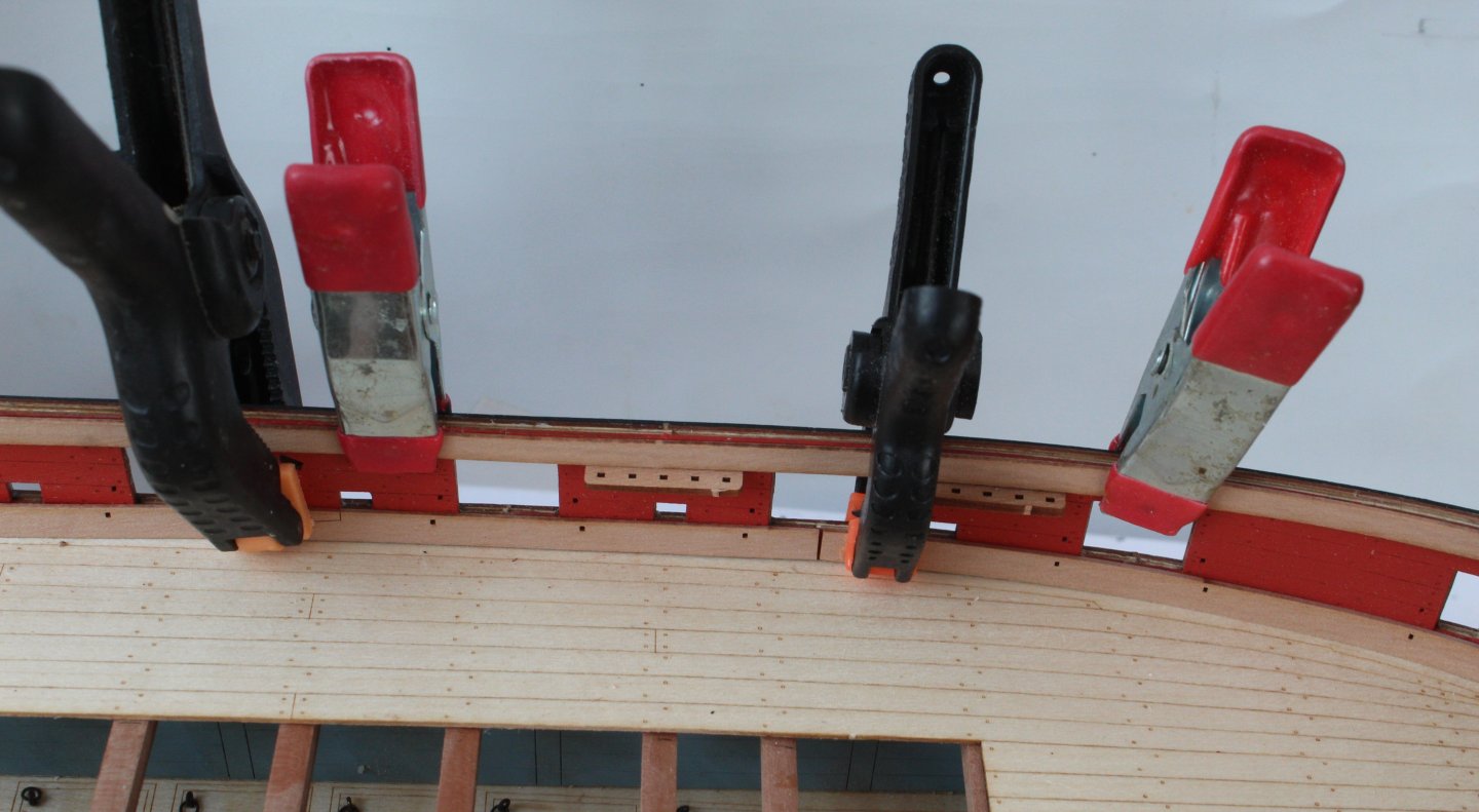
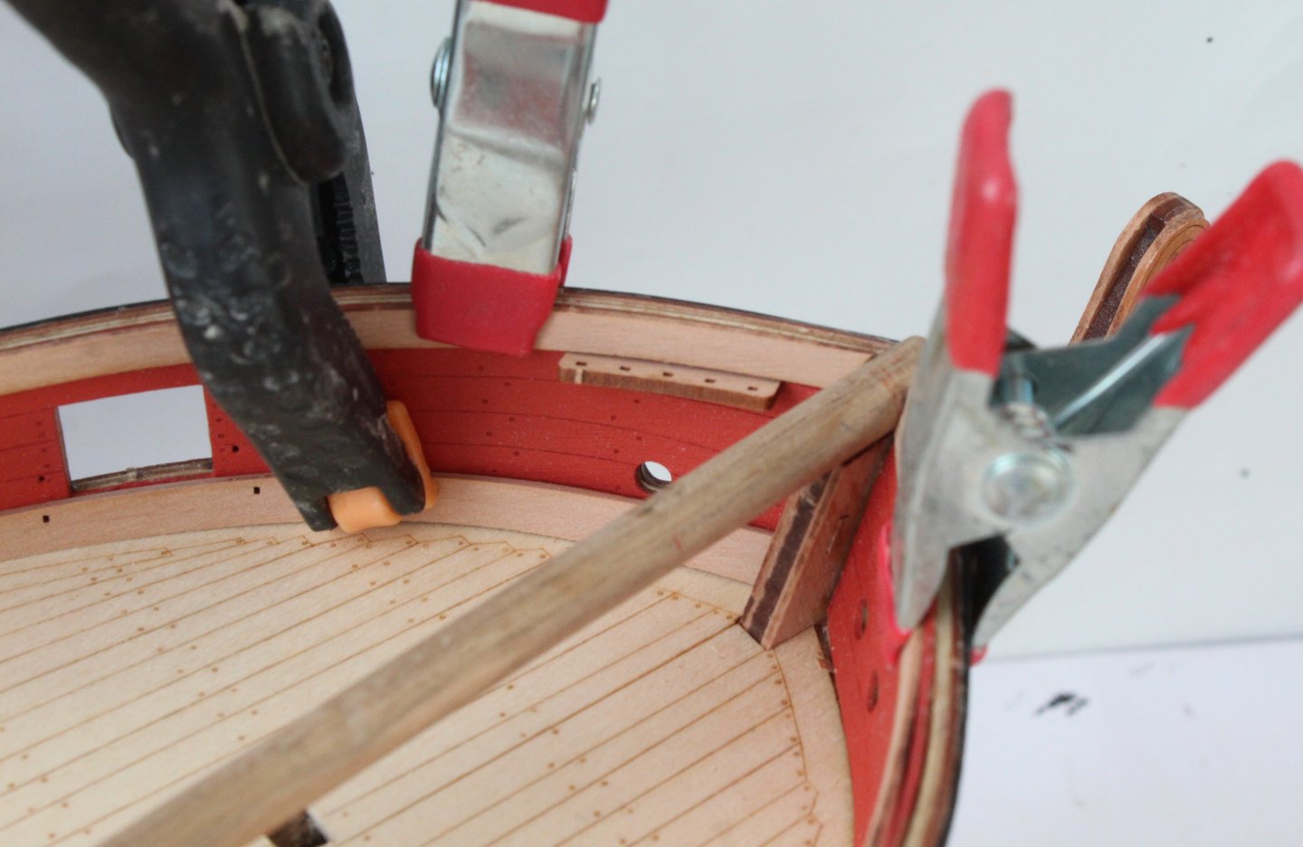
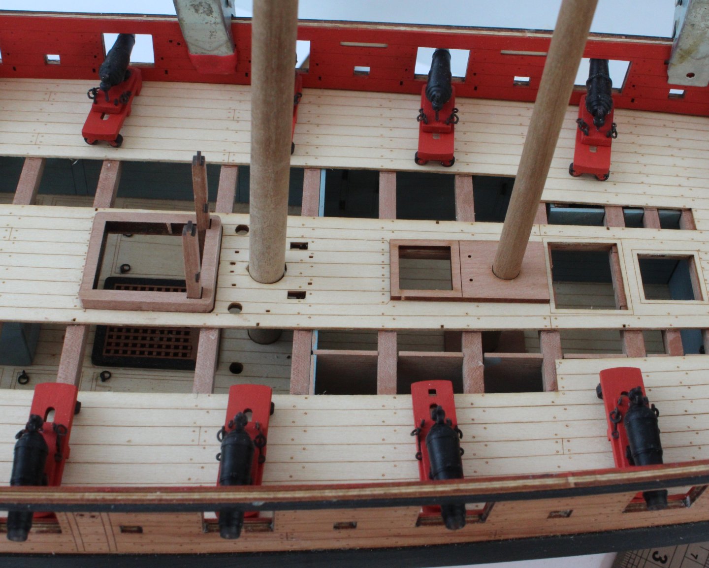
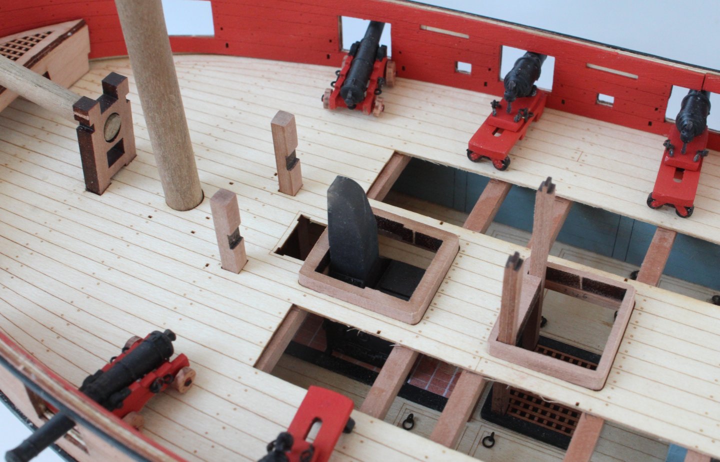
It has been one of those days were I have spent plenty of time in the shipyard but have not really made that much progress. I started by fitting the bow spirketting patterns. This took some time as I need to make sure the holes provided for the eyebolts lined up with the holes on the bulwarks. Once I was happy with the overall fit the patterns were glued and clamped. I did insert a couple of eyebolts at each end of the spirketting, as can be seen in the photos below. It was then a case of repeating the process for the rear spirketting patterns. When they were glued in place I used three eyebolts to assist with the alignment, one at the front one int he middle and one at the rear. Before fitting the patterns I did check that an eyebolt would locate in each of the bulwark openings. In some case it was necessary to run a micro drill in the hole to remove some of the glue deposits. Once the glue had been given time to cure the clamps were removed. I then made a start at cleaning up and painting the gun port openings. Following on from a previous post with regards to the rear cabin roof / gunwale I did a trial fit. The left hand side does not require any remedial work. I will have to trim the top aft section of the right hand side bulwark however. Finally I did make a start on a margin plank for the deck / stern board joint. It still needs a little bit more work but so far so good.


- 241 replies
-
- 10
-
-
- Vanguarrd Models
- Harpy
- (and 1 more)
-
Thanks for the information. I plan test fit the gunwales and davits to see what needs doing on my Harpy.
-
An interesting approach. I like the use of a mirror. I noticed you have worked from outer to middle. I always go from middle to outer. Both ways end up with the same result.
- 426 replies
-
- 1
-
-
- Vanguard Models
- Sphinx
- (and 1 more)
-
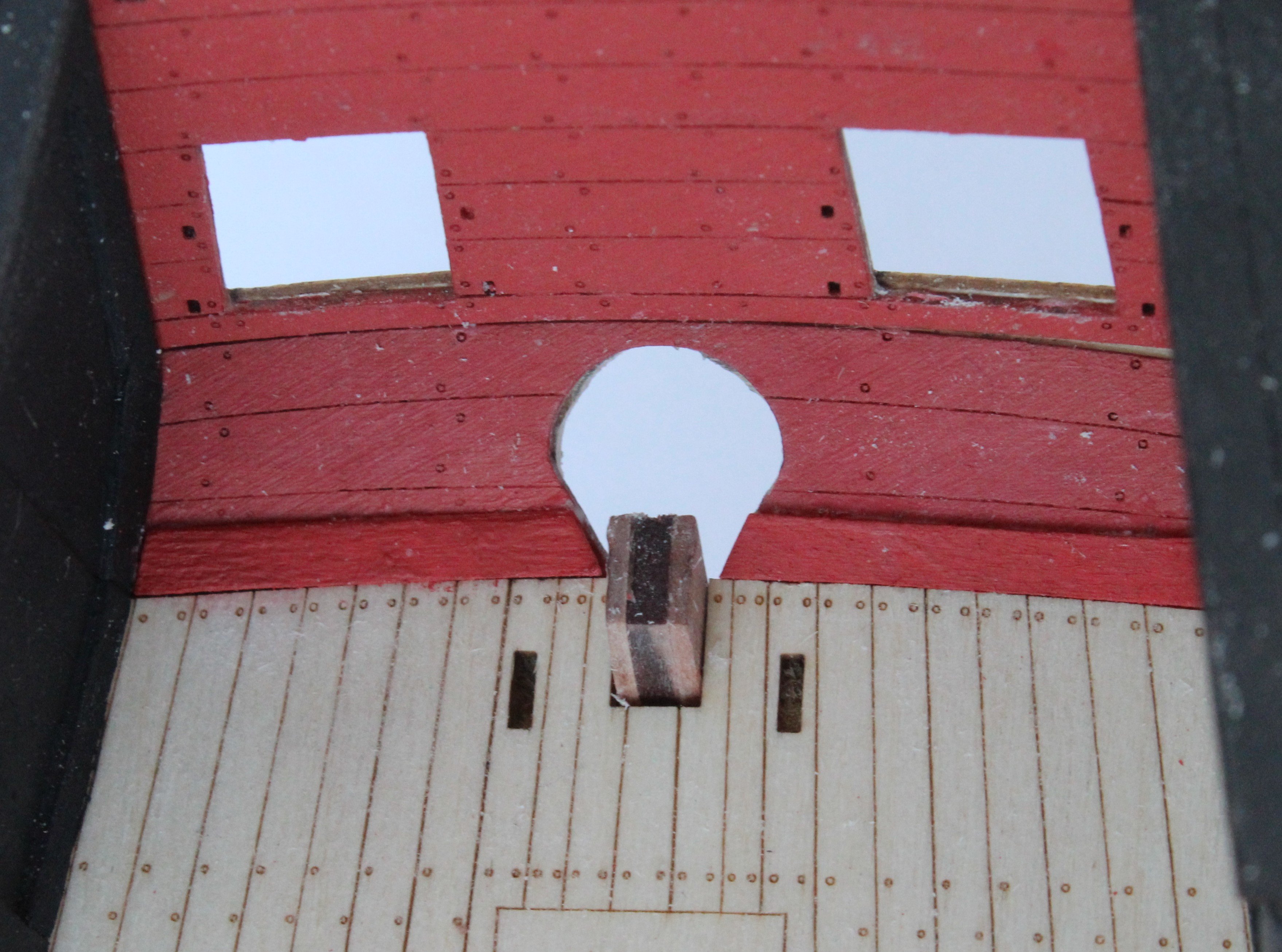
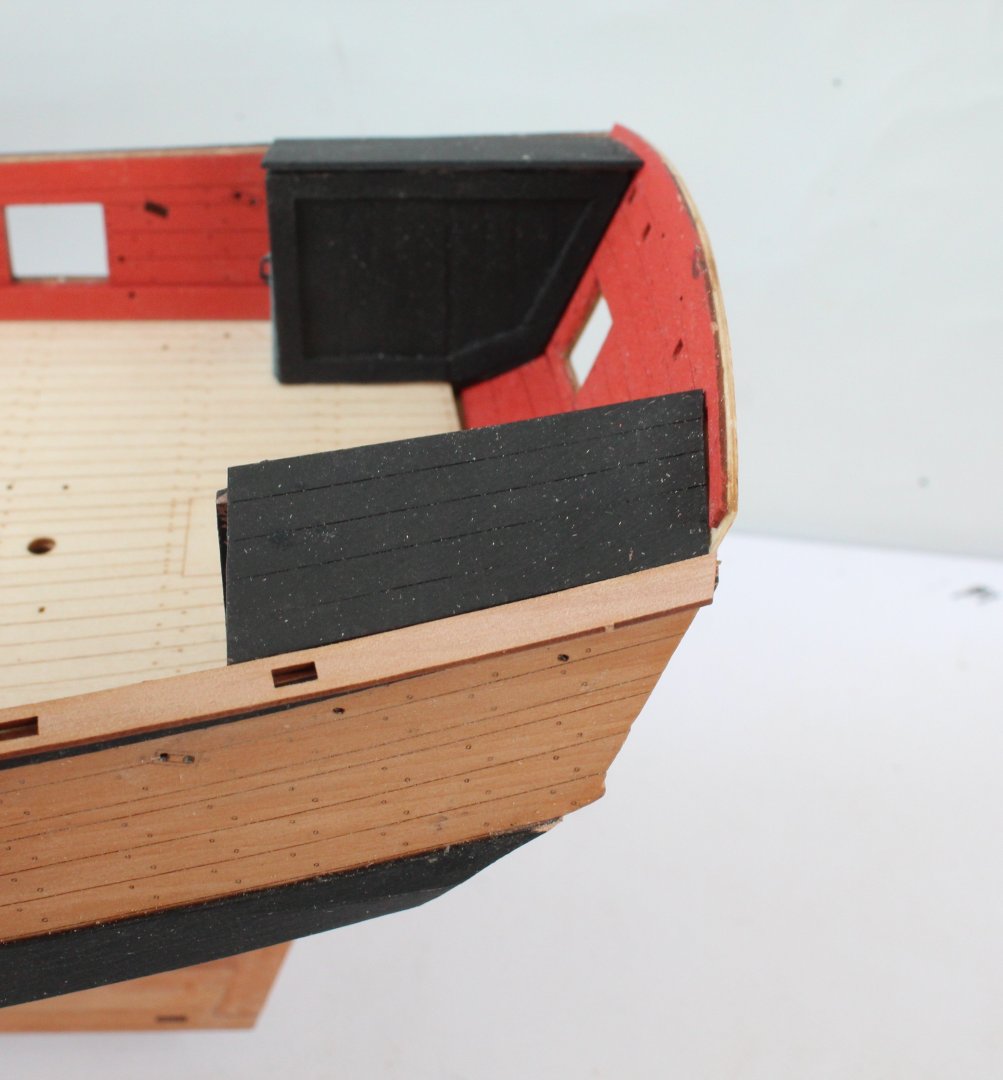
The roof of the two rear cabins have now been added. I have just noted @Blue Ensign comment on his build log regarding the position of the roof with regards to the gunwales and I have the same issue with the rear section of the gunwale being above the level of the cabin roof. I do not plan to do anything with this for the time being. I also plan to add a margin plank between the deck and stern board joint. My next task is to install the inner bulwark sheer rail and spirketting patterns. Experience has taught me that I need to check the position of the sheer rail with regards to the various belaying racks to ensure the racks can be installed without fouling with the bottom edge of the sheer rail. I plan glue the belaying rack in place before the sheer rail so that I can sure the racks are full engaged in the locating slots provided. In the photos below I am test fitting the sheer rail and spirketting patterns, both of which required a little bit of trimming. In the final photo below I am also making sure the bowsprit will fit through the hole provided at the bow. Before fitting the racks and patterns I will coat the various parts with sanding sealer and then paint, red for the patterns and black for the racks.
- 241 replies
-
- 15
-
-
- Vanguarrd Models
- Harpy
- (and 1 more)
-
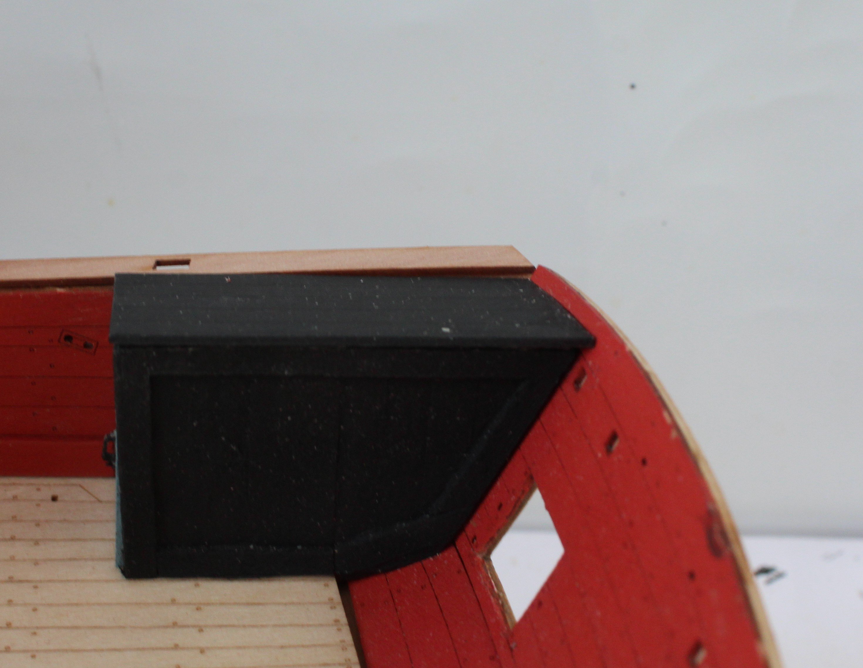
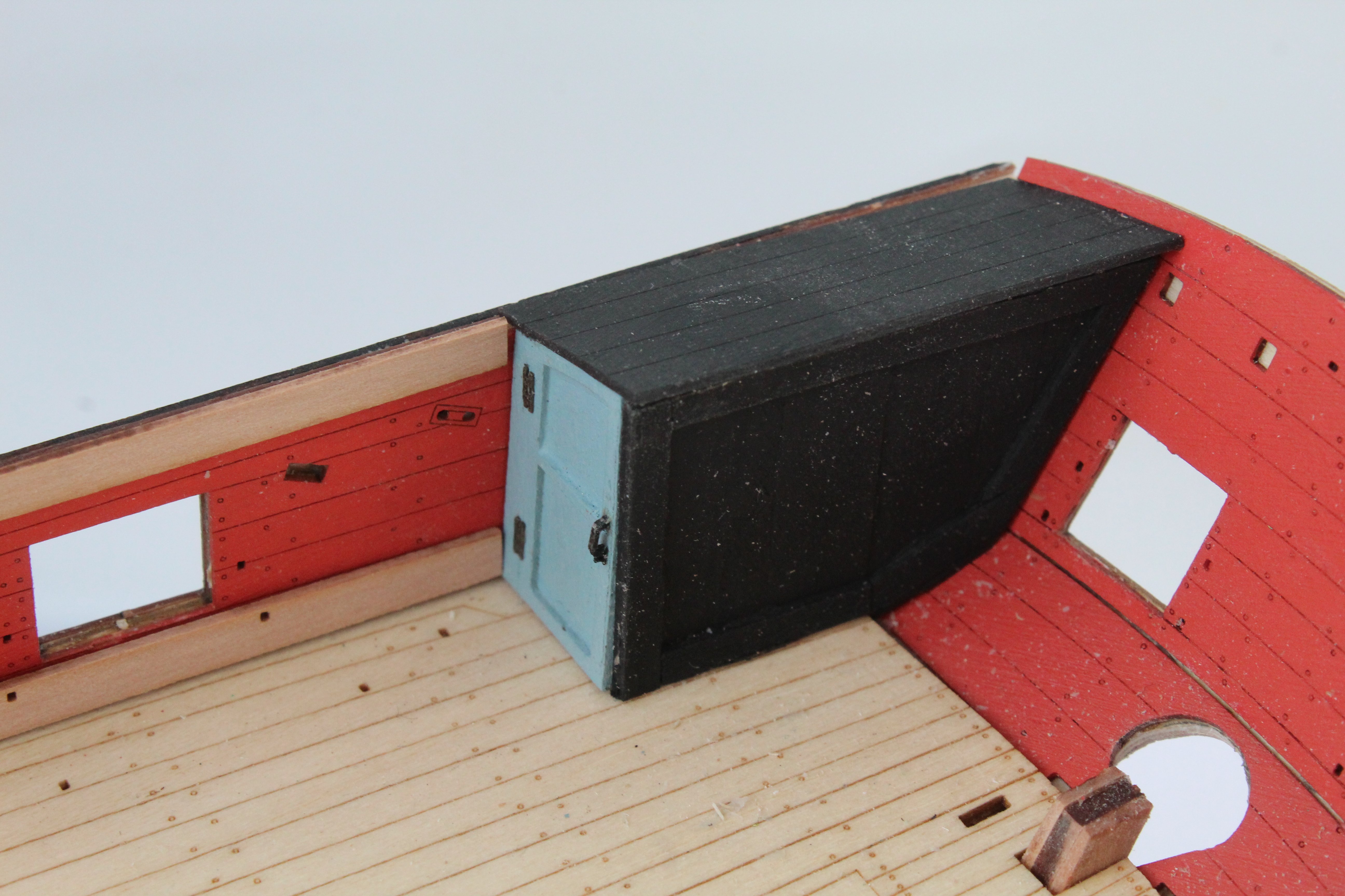
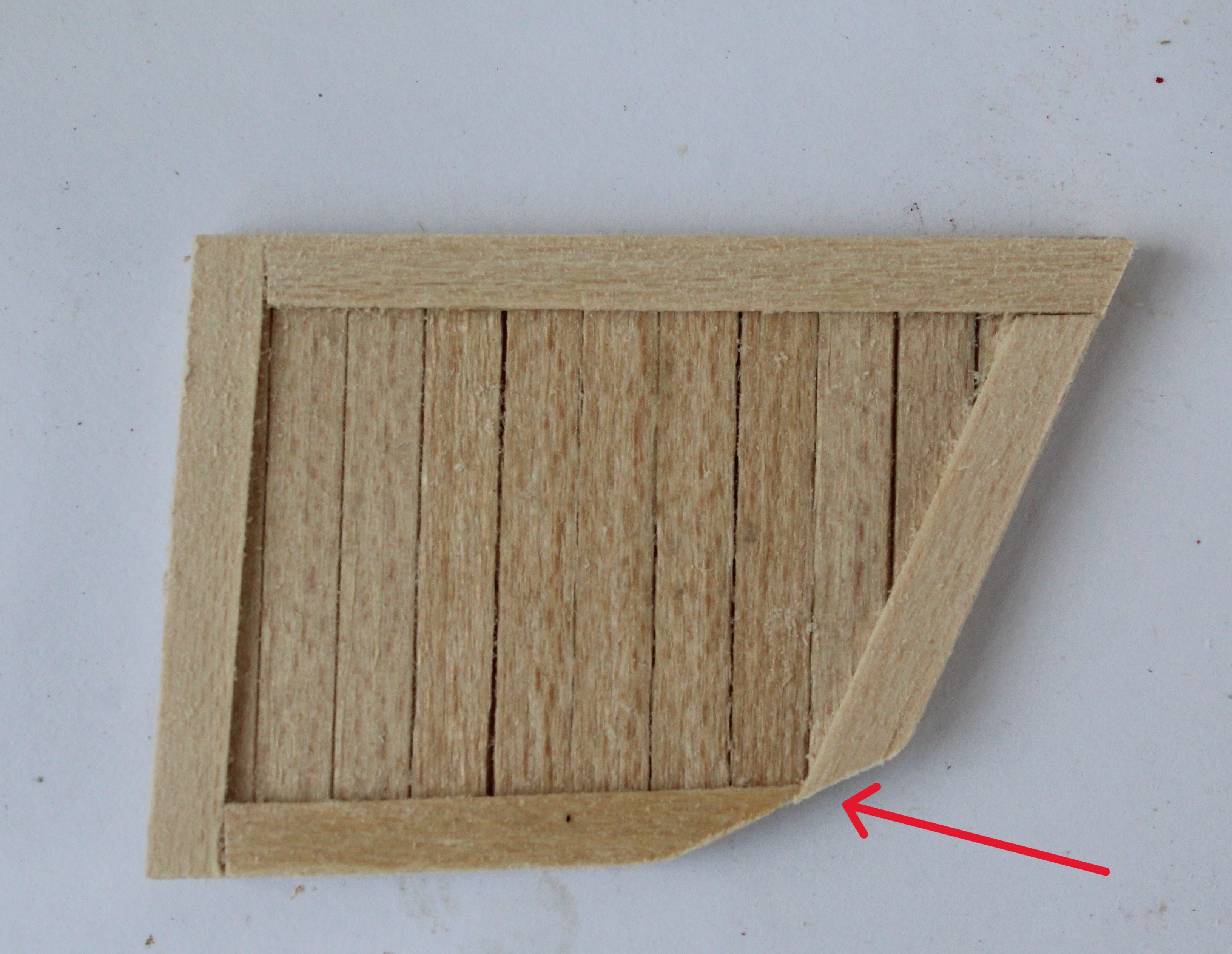
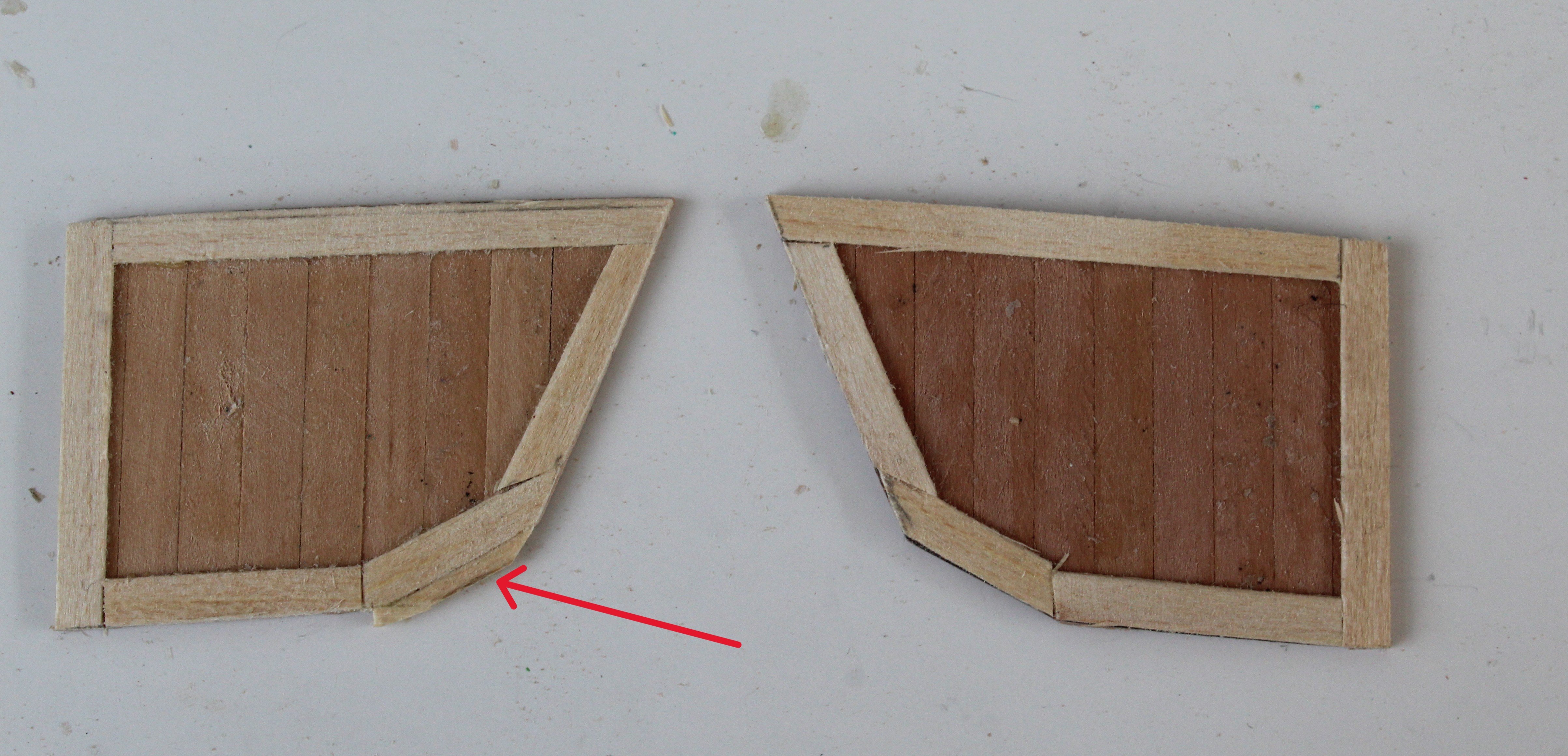
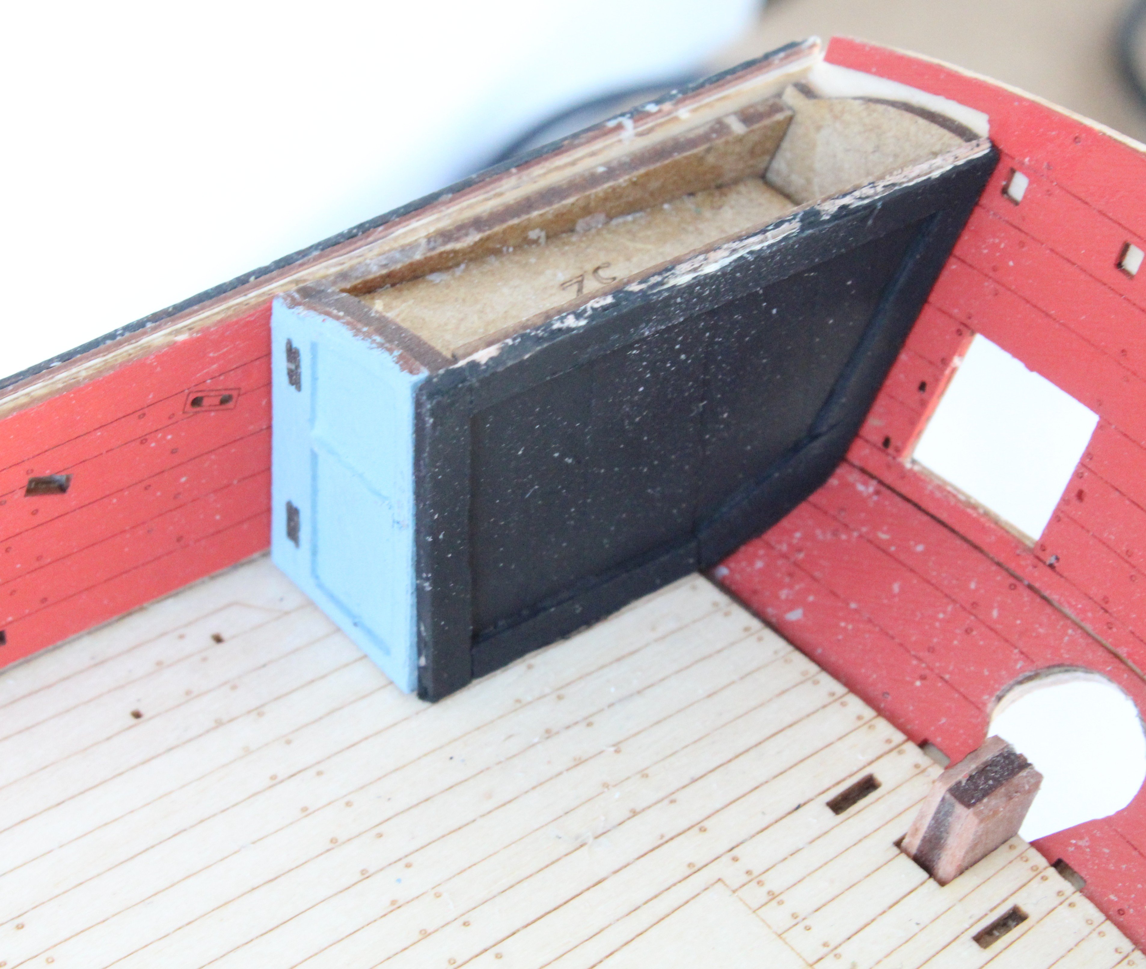
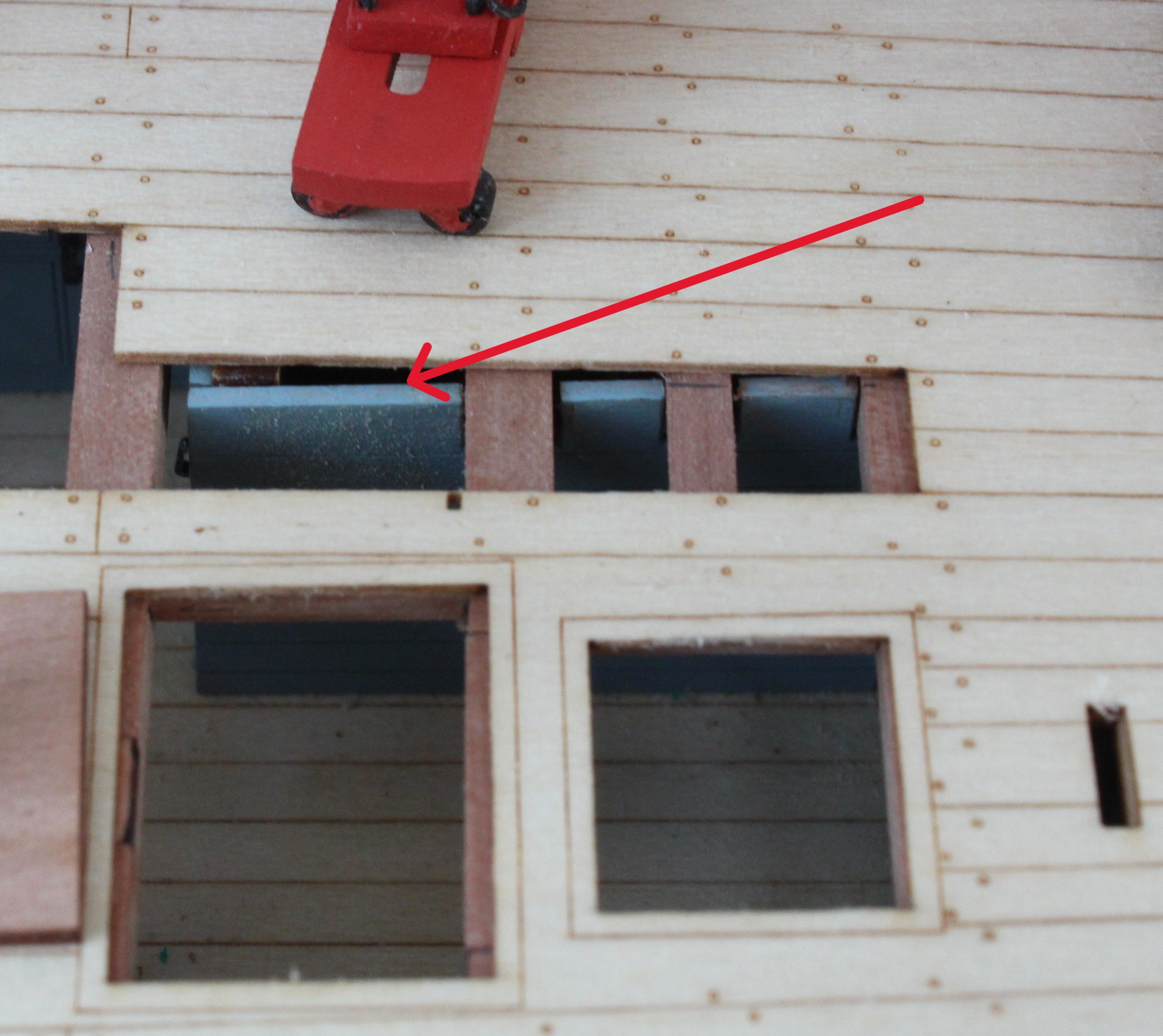
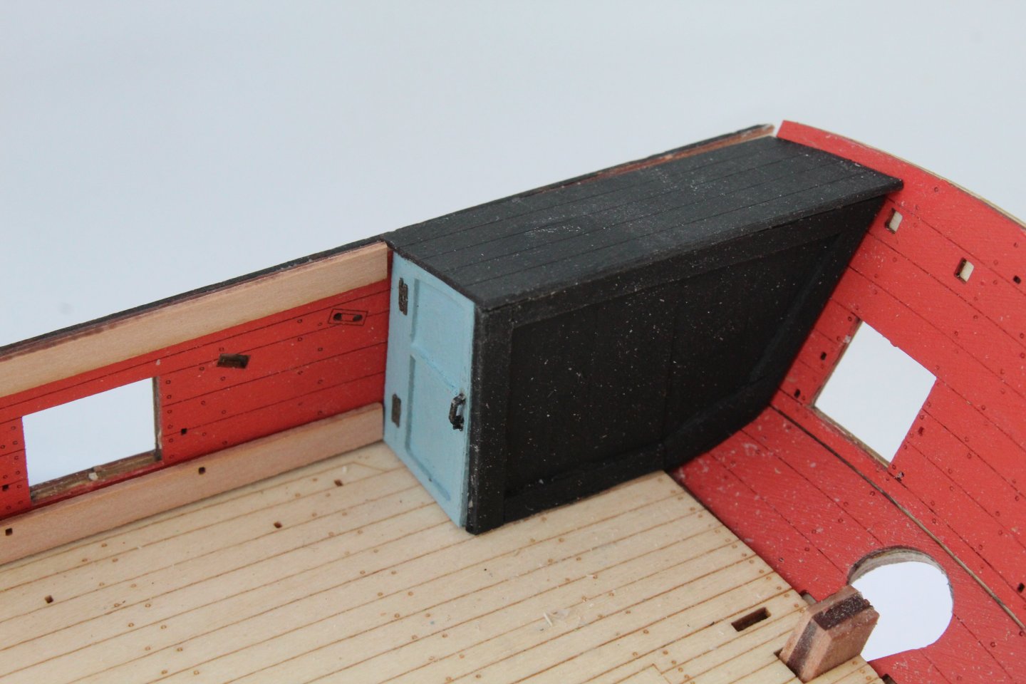
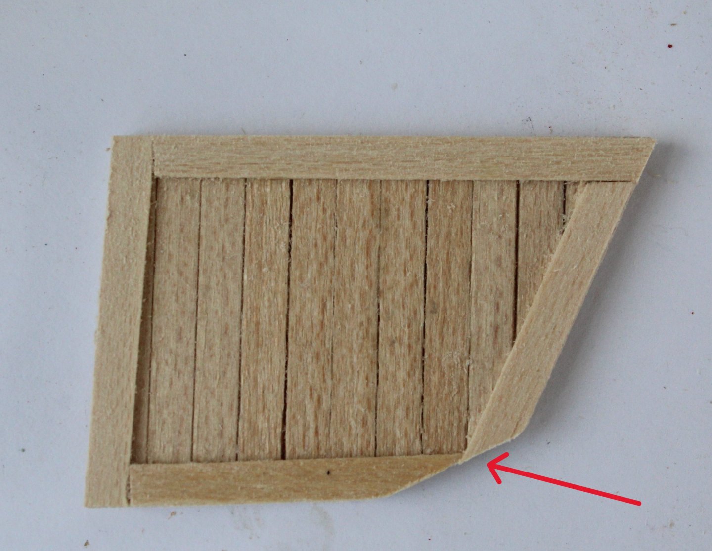
The inner bulwark patterns have now been glued and they were left overnight to allow plenty of time for the glue to fully cure. I did use the gun port jigs to ensure the patterns were correctly aligned. I then turned my attention to the rear cabin side panels. Having made a template which was a good fit I decided the kit supplied patterns could not be trimmed to get a nice looking fit. Therefore I opted to make some new side cabin pieces. I cut some lengths of 4mmW planking material which were then glued together. The template was then used to draw the required outline on the glued planks. To complete the process I added the outer framing strips and the assembly was then trimmed to match the template. I ended up rejecting my first one due to any error with the framing, as shown below. I was much happier with my second attempt, albeit I did need to add an additional filler to the right hand side panel. After sealing and painting the side panels black they were added to the Harpy along with the doors. In the photo below the door handle is missing in action. The missing door handle has now been attached and I have also dry fitted the roof section. I need to make sure it is a good fit with the top edge of the side panel before gluing it in place.


- 241 replies
-
- 11
-
-
- Vanguarrd Models
- Harpy
- (and 1 more)
-
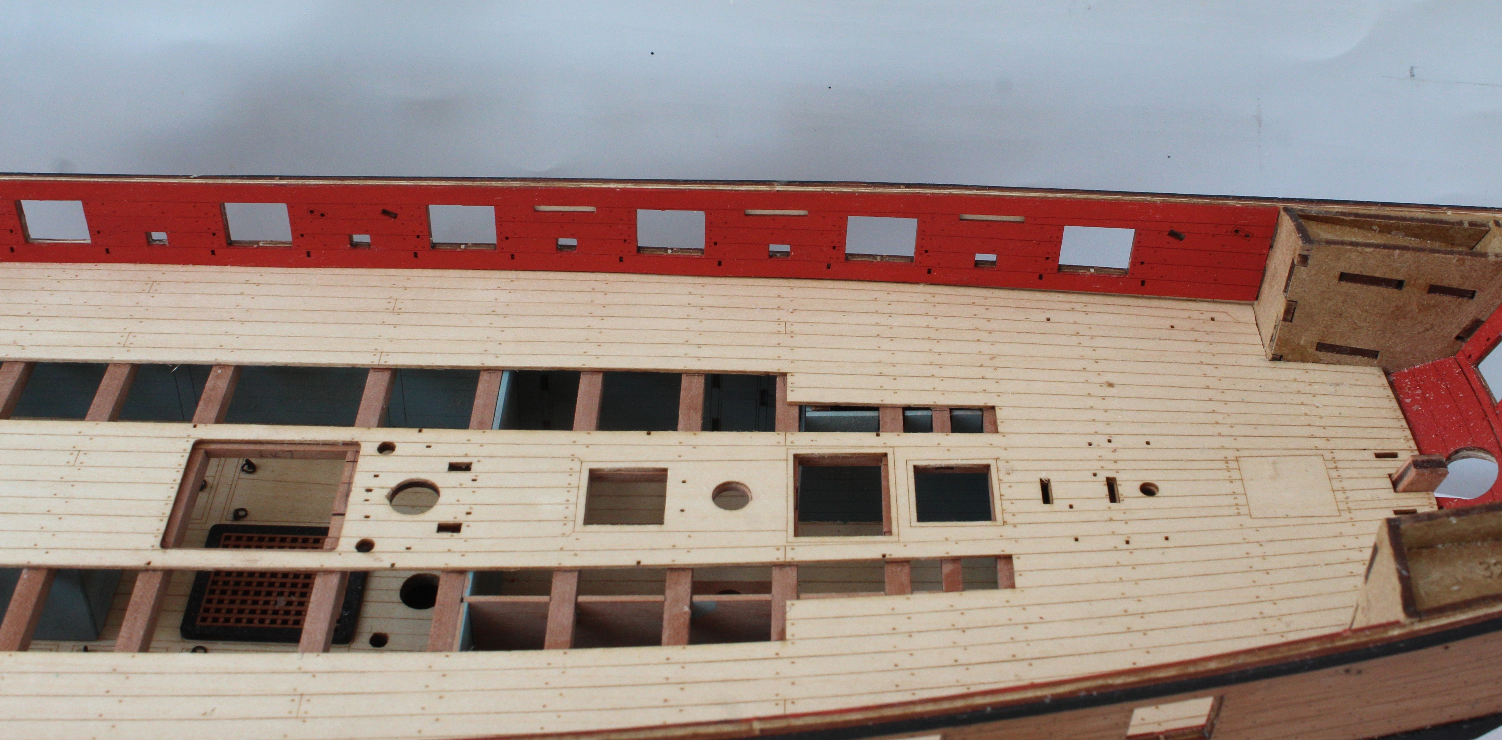
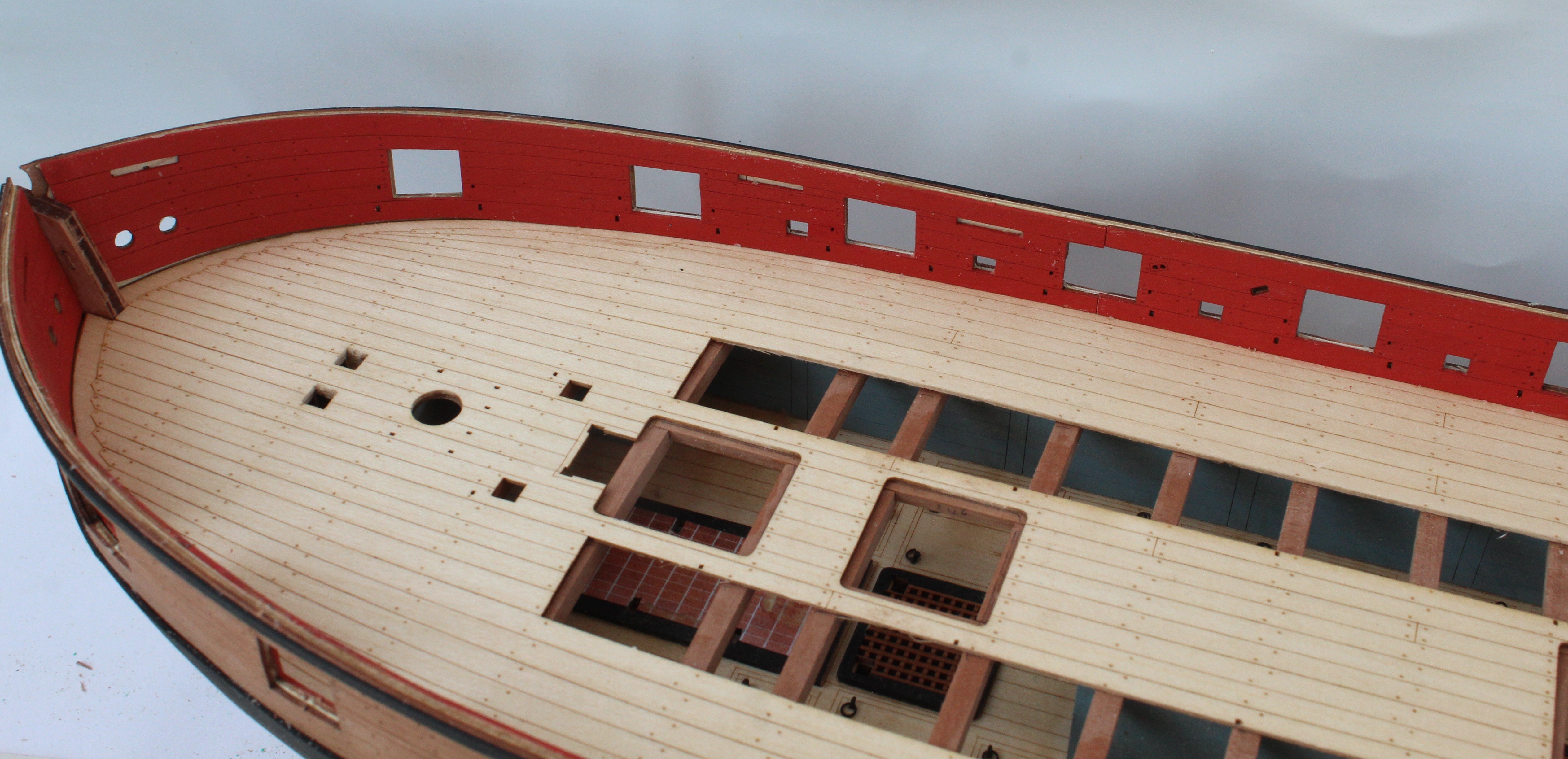
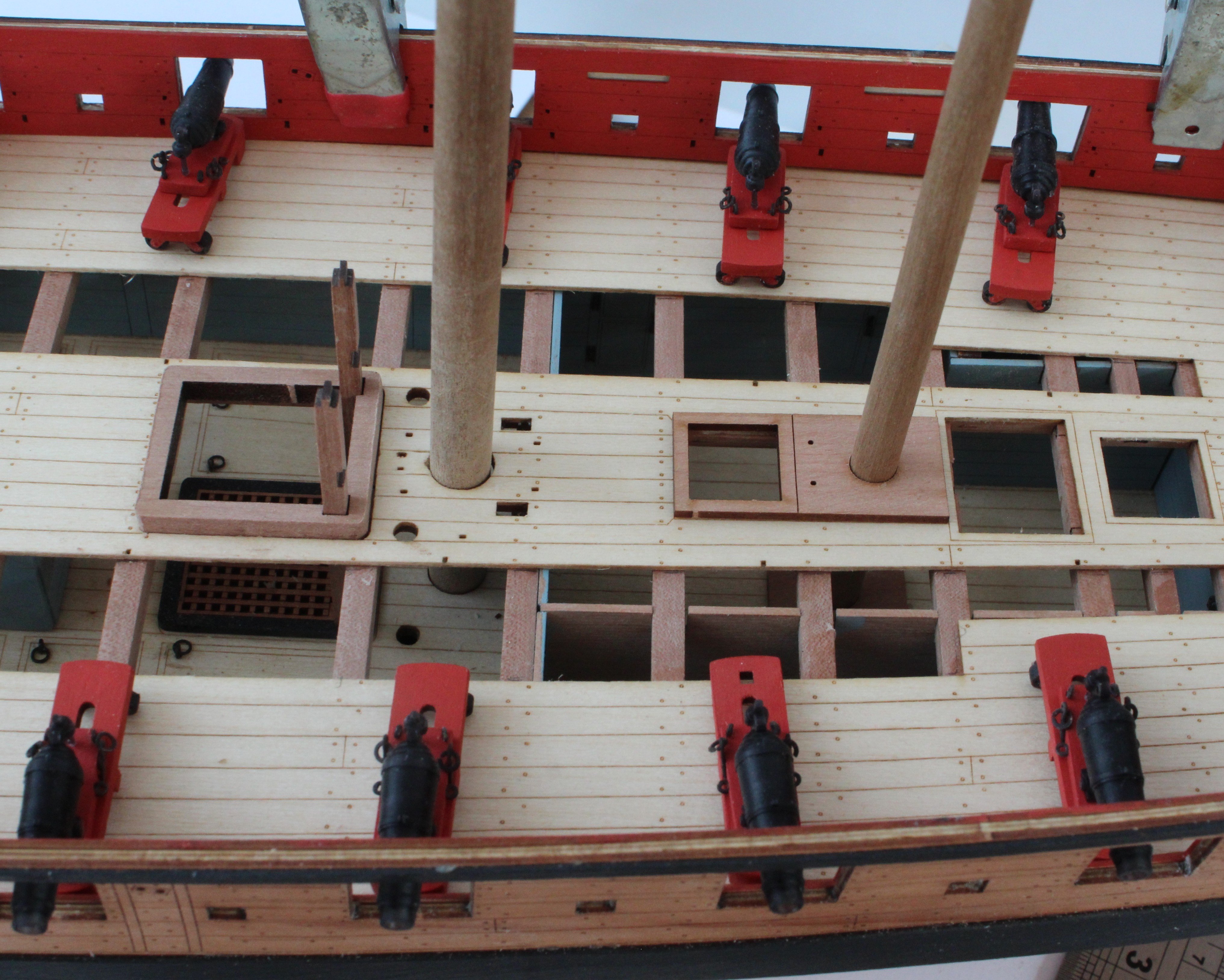
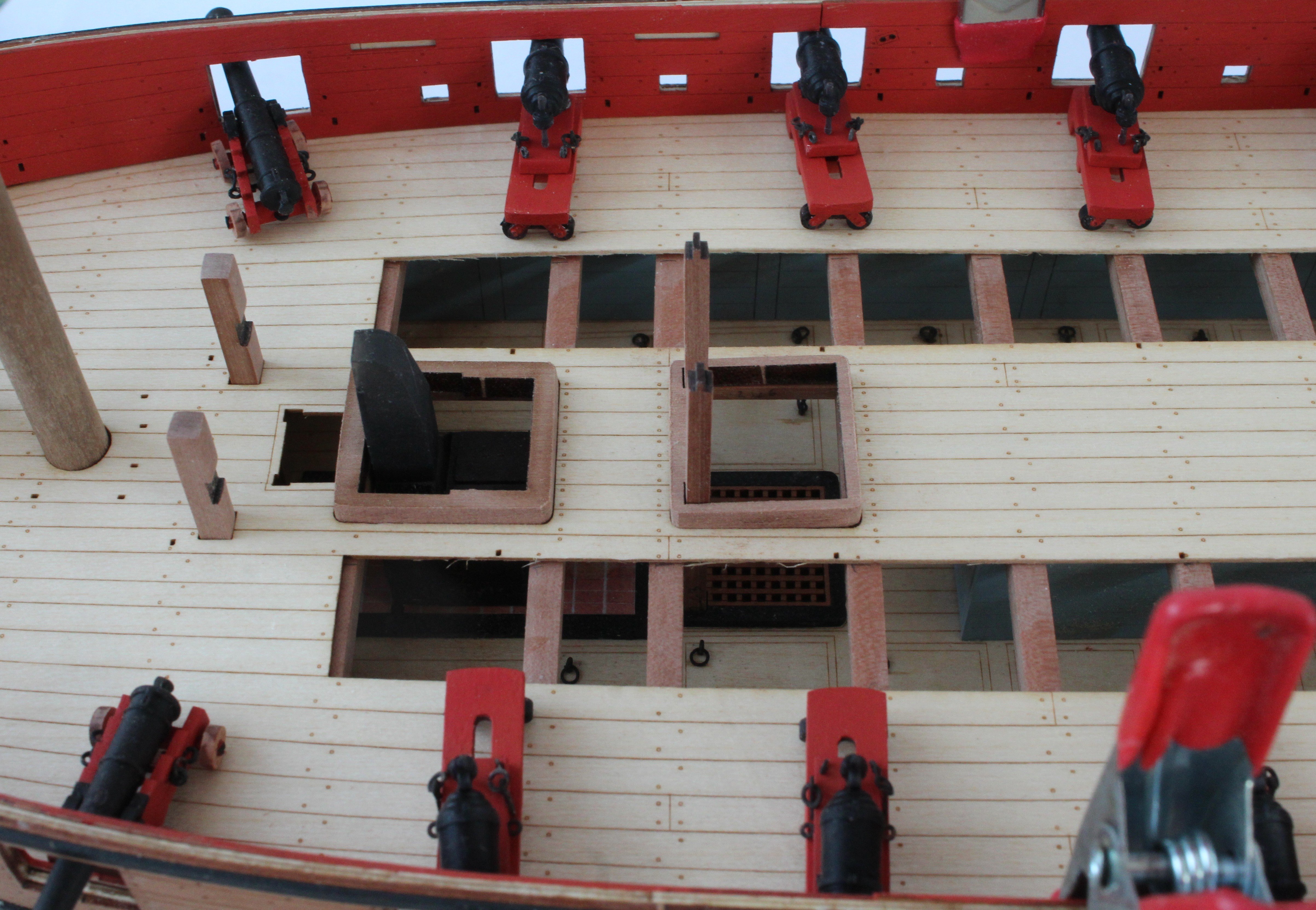
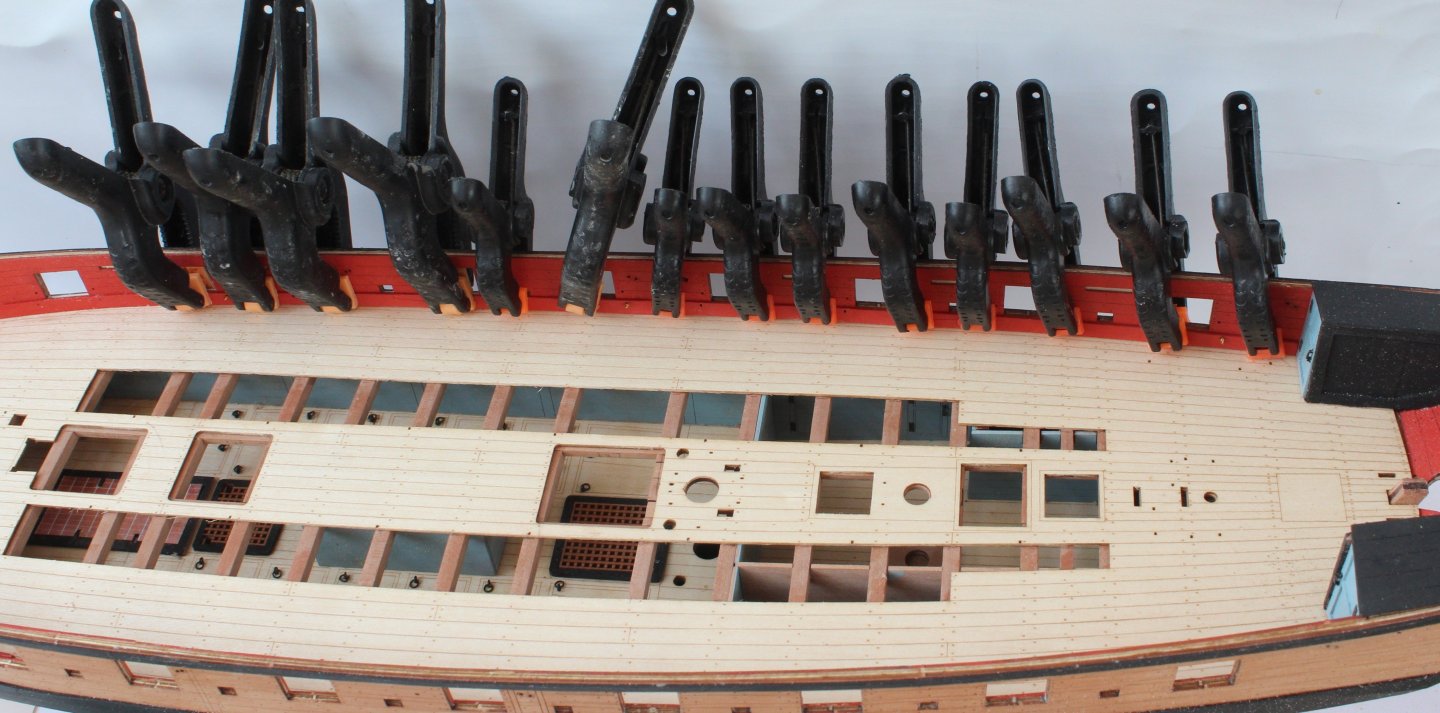
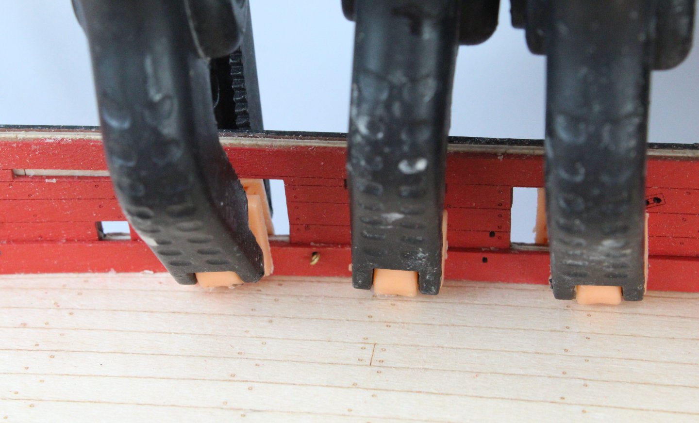
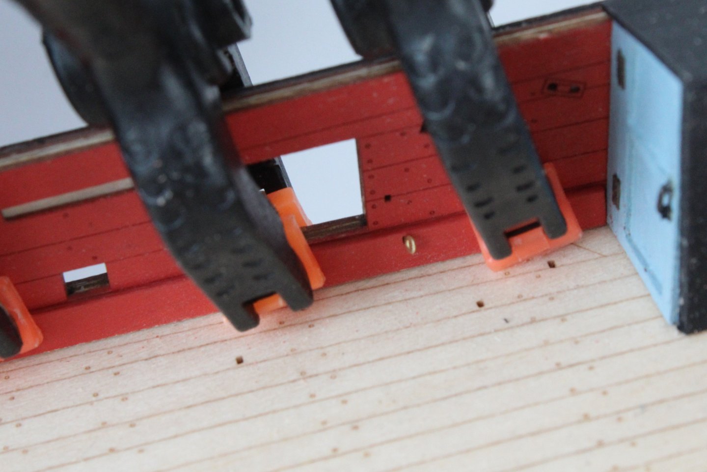
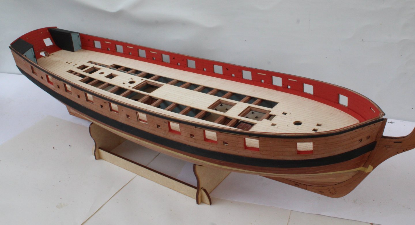
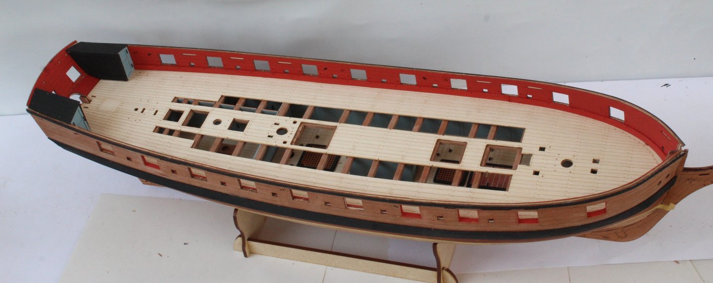
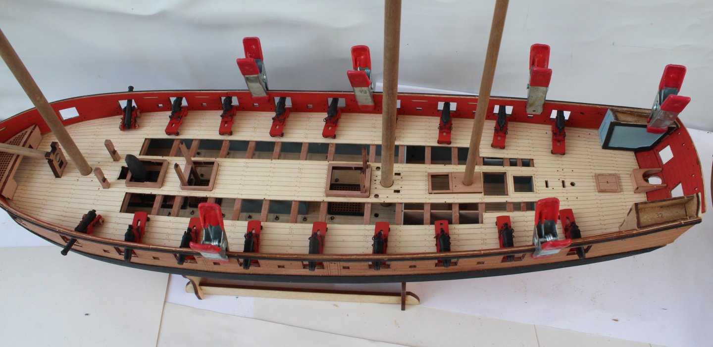
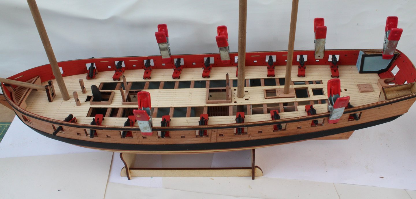
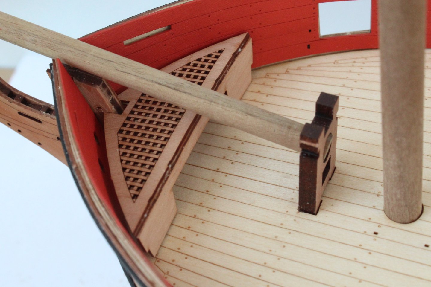
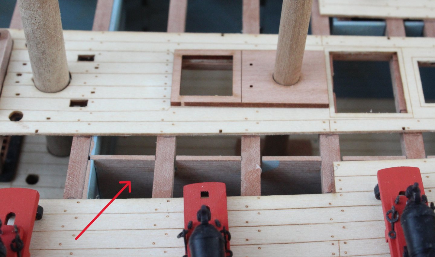
I have returned to the shipyard after a busy two days looking after our youngest 1 year old granddaughter. The upper, laser etched, deck pattern has now been glued in place and was left for 24 hours to give the glue plenty of time to cure. I then decided to dry fit some the upper deck items and patterns. I am very happy that these items seem to fit perfectly as can be seen in the next two photos. My next task will be to glue the inner bulwark patterns in place. The next photo shows the stern area, noting I still have to shape the rear cabin side patterns. The next three photos shows the midship section(s). The next photo shows the bow area, the front grating assembly will require a little bit of fettling to get a good tight fit. I might add a little shaped deck infill so it follows the line of the lower partition, as can be seen in the photo below I can either paint the inner face of the visible partition shown in the photo below or I could add a filler piece so the inner face of the partition is not visible. I will probably try to paint the partition.


- 241 replies
-
- 11
-
-
- Vanguarrd Models
- Harpy
- (and 1 more)