Glenn-UK
-
Posts
3,175 -
Joined
-
Last visited
Content Type
Profiles
Forums
Gallery
Events
Everything posted by Glenn-UK
-
 Many thanks, I think spending time correcting my countless errors is paying dividends. 😀
- 476 replies
-
- 3
-

-

-
- sphinx
- vanguard models
- (and 1 more)
-
Thanks @DelF. It seems to be a mystery. I thought I had found fool proof with aligning the shroud deadeyes, it would appear I am the fool 🤣
- 476 replies
-
- 2
-
-

-
- sphinx
- vanguard models
- (and 1 more)
-
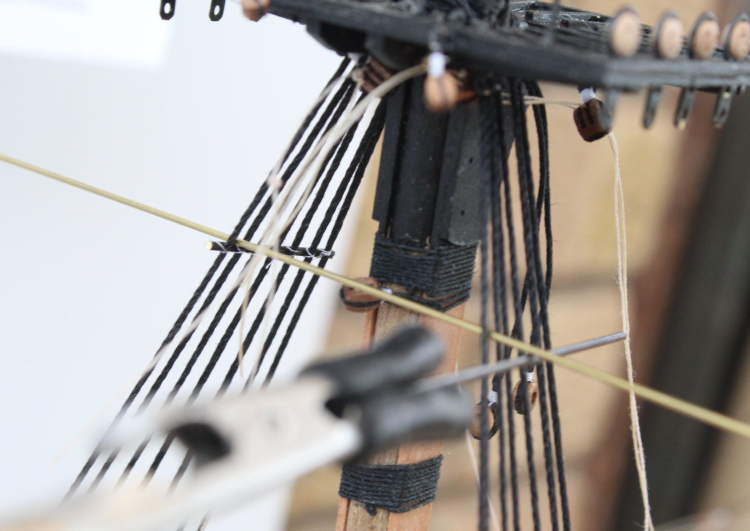
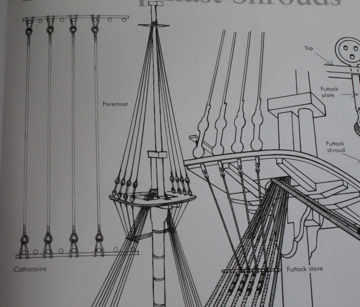
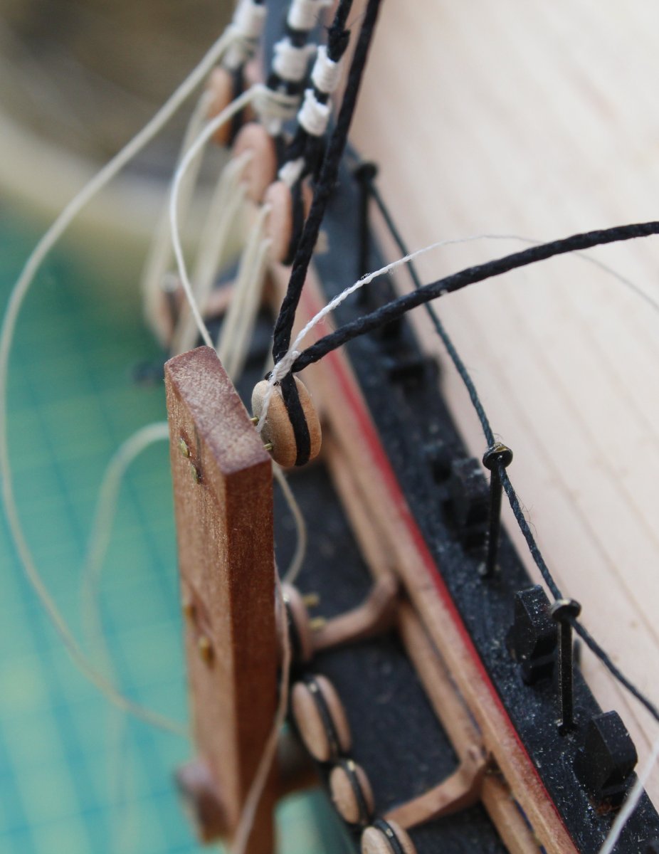
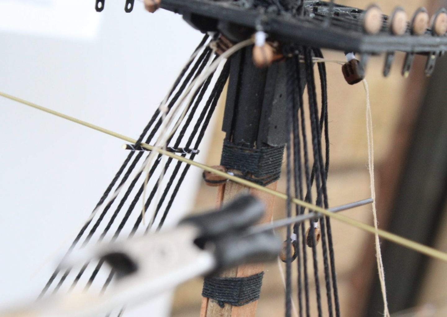
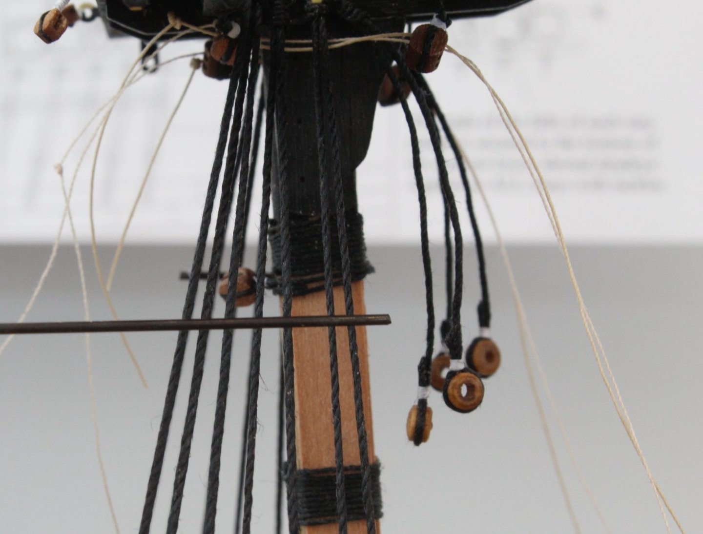
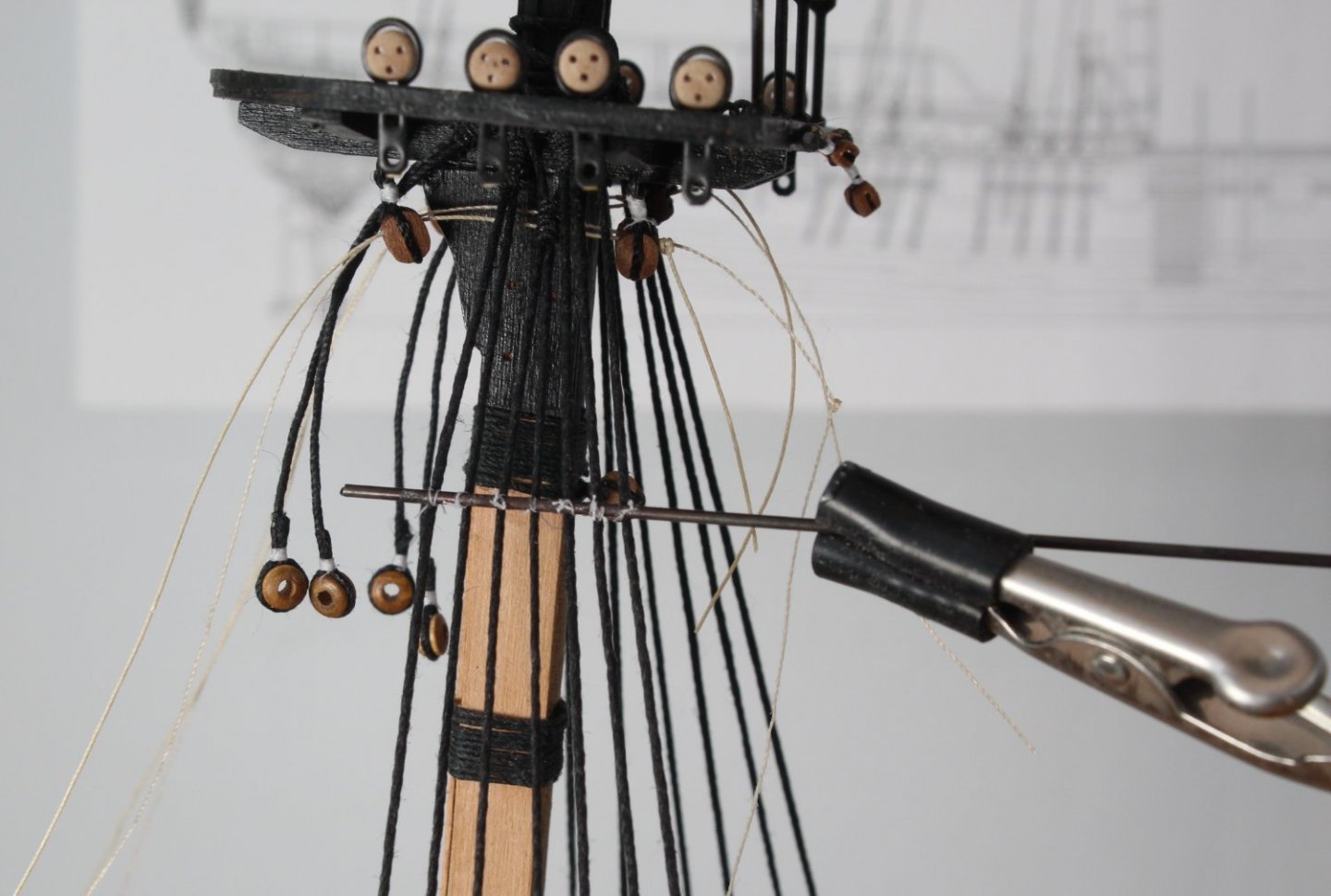
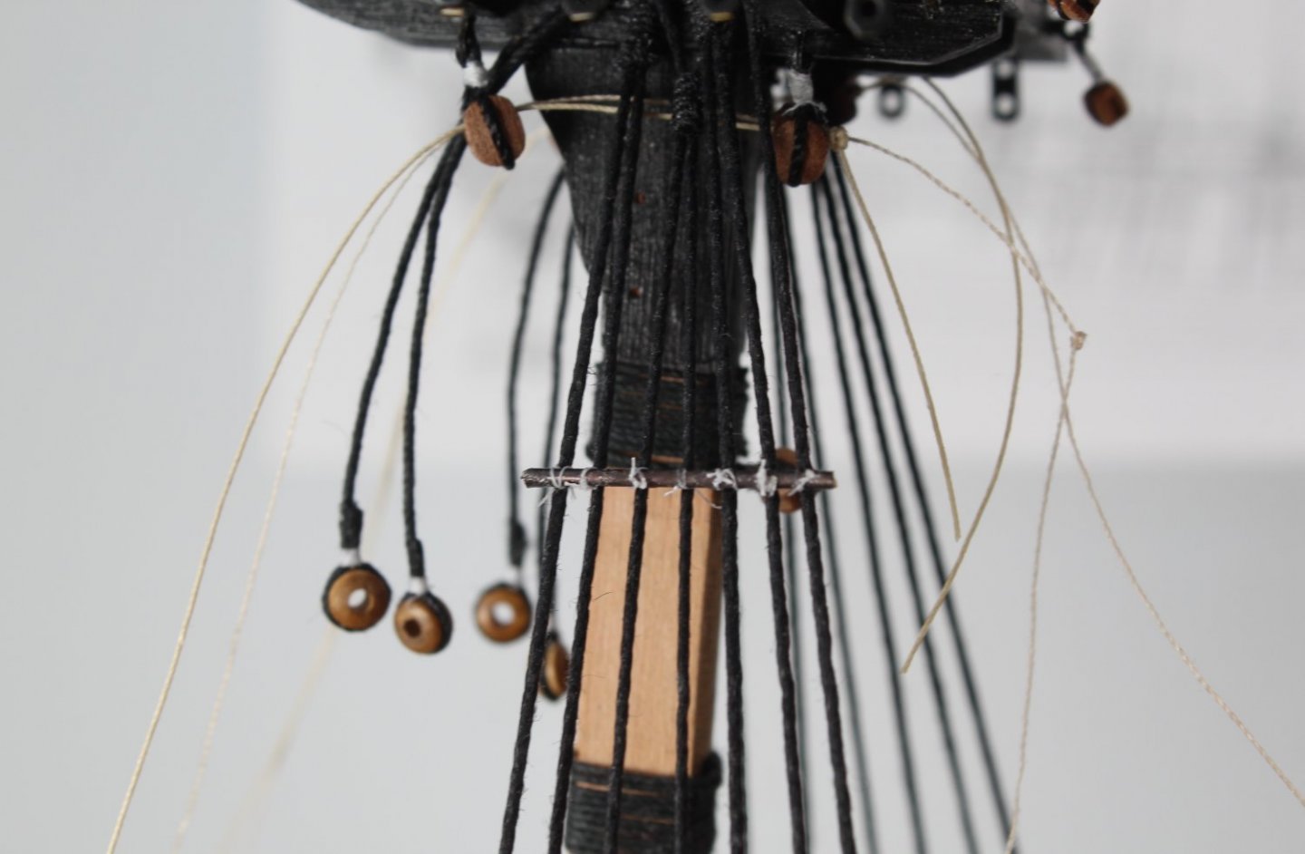
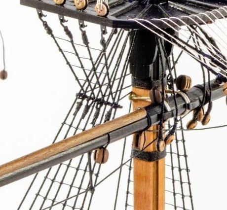
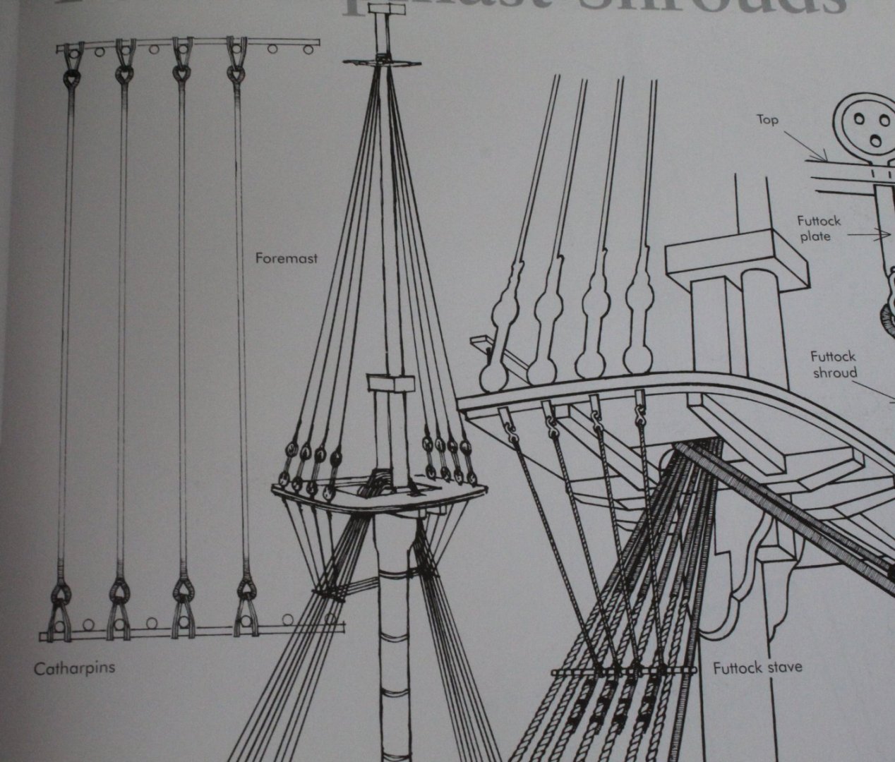
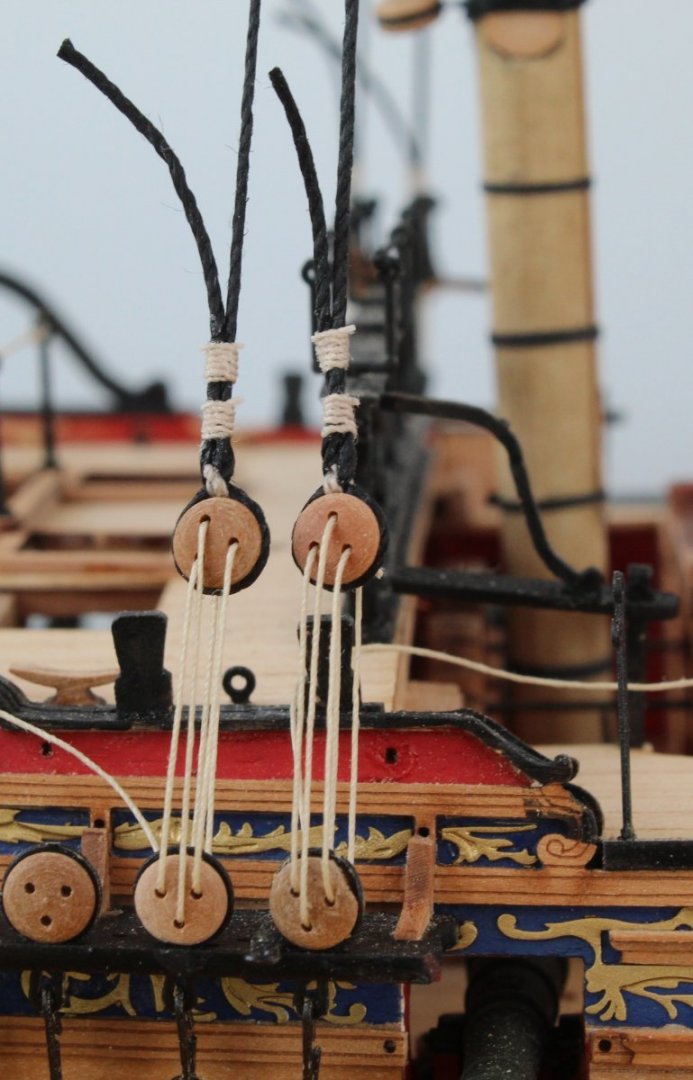
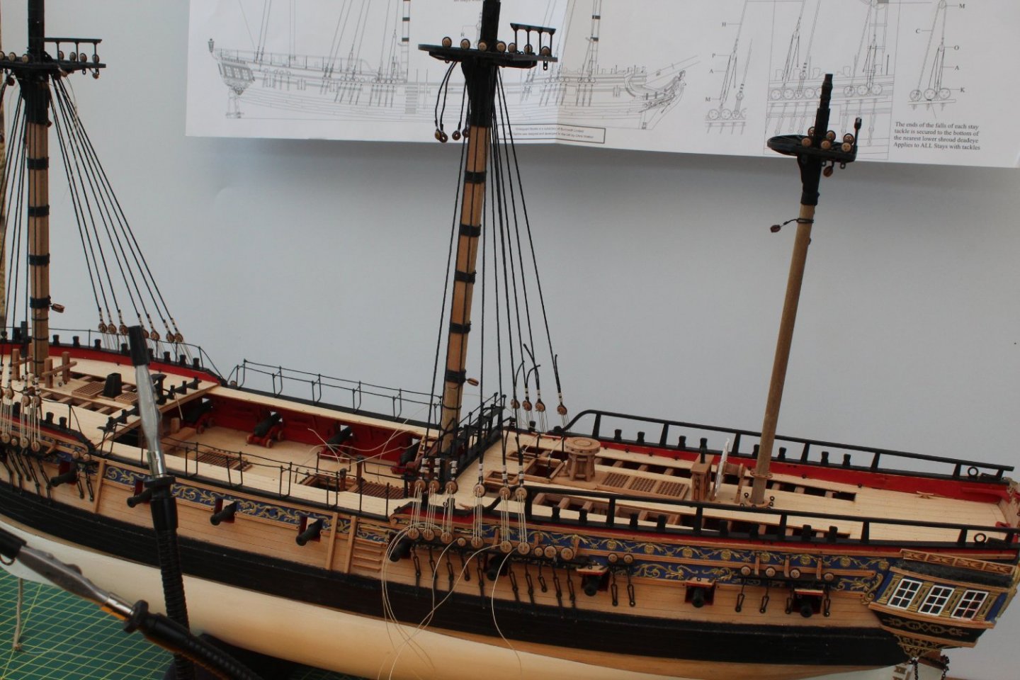
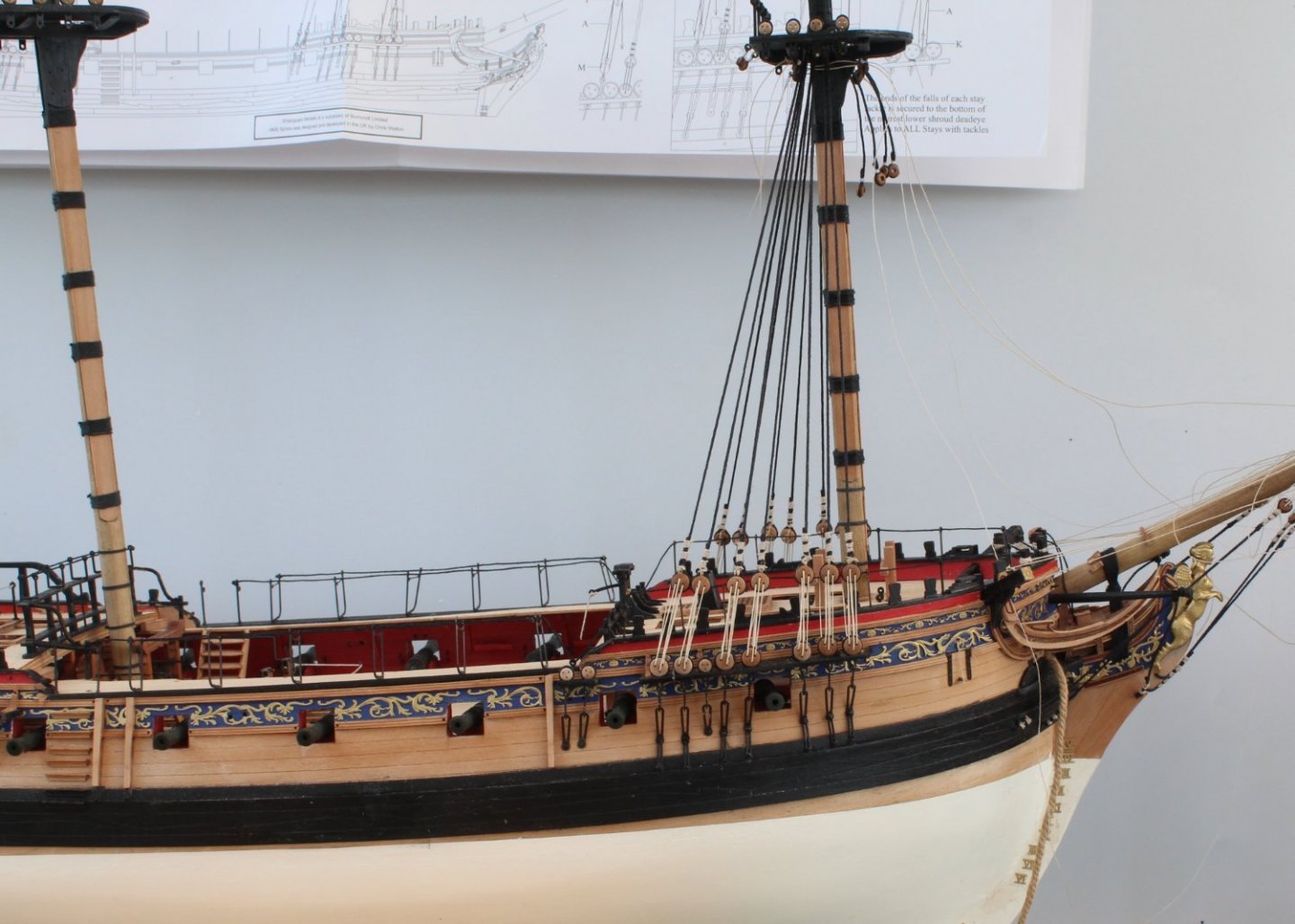
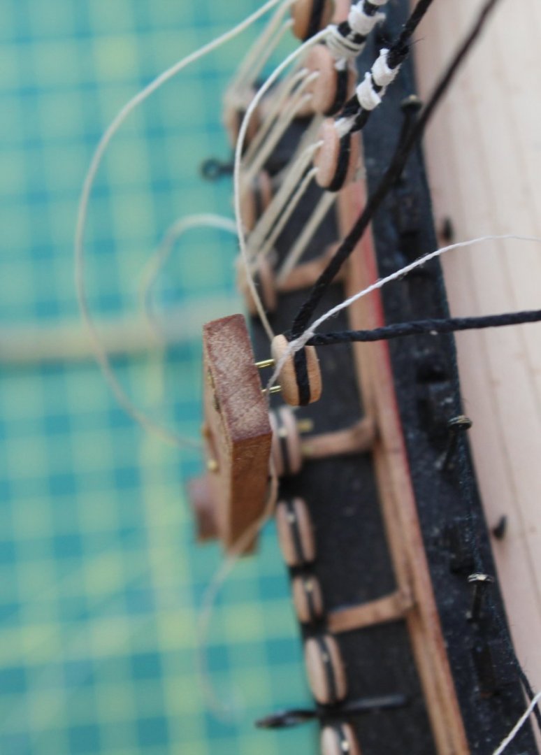
Catharpins Foremast - A False Start The first task with regards to the catharpins is to fit the brass rods to the shrouds. The 1mm brass rod supplied with the kit was cleaned in acetone and hot soapy water and then chemically blackened. The brass rod was then held in position on the port side shroud using a quad hand, as can be seen in the photo below. So far so good! With the brass rod held in position I used some fly tying thread to secure it to the shrouds. It is not my best work but the thread will be dyed black with Indian ink so will look OK. The brass rod is now ready for trimming to the correct length. With the brass rod trimmed, as shown in the photo below, I am ready to move on to the starboard side to repeat the above process. Unbeknown to me however I had made a fundamental error! This seems to be a core theme with my build log journey for the Sphinx. The more eagled eyed of you might have spotted the error. Fear not if you haven't as all will be revealed after the next next photo. Moving on to the starboard side I used a length of brass rod to check the position to ensure it was set to the same height as the port side. This is when I noted that the thread links between the two brass rods, when installed, would foul with the rigging block affixed to the rear of the foremast. I found it difficult to find a picture that clearly shows the problem, the one below is the best of a bad bunch. The middle and inner cross threads would be at the same level as the rigging block based on the level set on the port side brass rod. It did not occur to be to check this sooner. In the photo below I have reset the position of the starboard side brass rod so the cross threads will now avoid fouling with the rigging block. The brass rod is ready to be fixed to the shrouds. Once this is complete I will remove the brass rod from the port side and reposition so it is lower and level with the starboard side. Hopefully this will be easy to do.
- 476 replies
-
- 9
-
-
- sphinx
- vanguard models
- (and 1 more)
-
It great to see the innovations incorporated in this design. It looks like it is going to be an amazing model.
- 488 replies
-
- 7
-
-
- Indefatigable
- Vanguard Models
- (and 1 more)
-
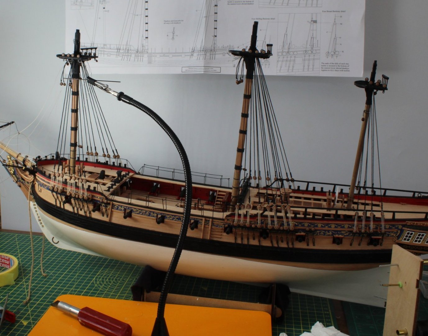
Lower Mast Shrouds All the lower mast shrouds have been fitted and the lanyards rigged. The seizing's have also been dyed black with Indian ink. My skills in this aspect of rigging are much improved but there is still plenty of room for improvement. The area which still seems to cause me some problems is getting the shroud deadeyes positioned at the same level. On the other hand a degree of unevenness is more representative of the shroud deadeyes on the real ships. Catharpins The next task will be to add the catharpins, which are the short ropes tied between the port and starboard shrouds for stabilisation and to prevent the shrouds interfering with the yards. On all my previous builds this is one area I have always struggled with. In Lennarth Petersson book "Rigging Period Ships" each catharpin is shown as a length of rope with loops on each end. The two loops are used to secure the catharpins to the shrouds. I might experiment to see if this is a viable option. I think the problem will be determining the correct length for each catharpin rope. In the past I have looped the catharpin thread around the brass road and then formed the loop by added a seizing to the catharpin thread to hold it in place. This has always proved to be difficult to implement due to the limited space available. Also I have always ended up with a slightly twisted shroud which is a problem with over tensioning the catharpins. In Jim's prototype build the catharpin thread appears to be taken over the top of the brass rod and is then seized to the front of the shroud line. The catharpins are positioned to meet the brass rod next to where the futtock staves pass. After passing behind the brass rod, the futtock staves are seized to the back of the shroud along with the catharpins at the front. This is another method which I have not tried before but it looks much easier to implement so is a method I will experiment with.

- 476 replies
-
- 6
-
-
- sphinx
- vanguard models
- (and 1 more)
-
This is one I thinking about doing after Sphinx and before the Indy. Looks a very nice one to build.
- 16 replies
-
- 2
-
-
- Ranger
- Vanguard Models
- (and 2 more)
-
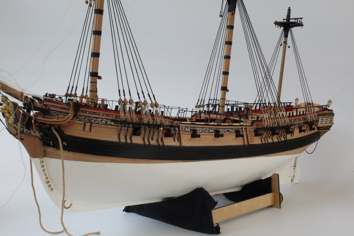
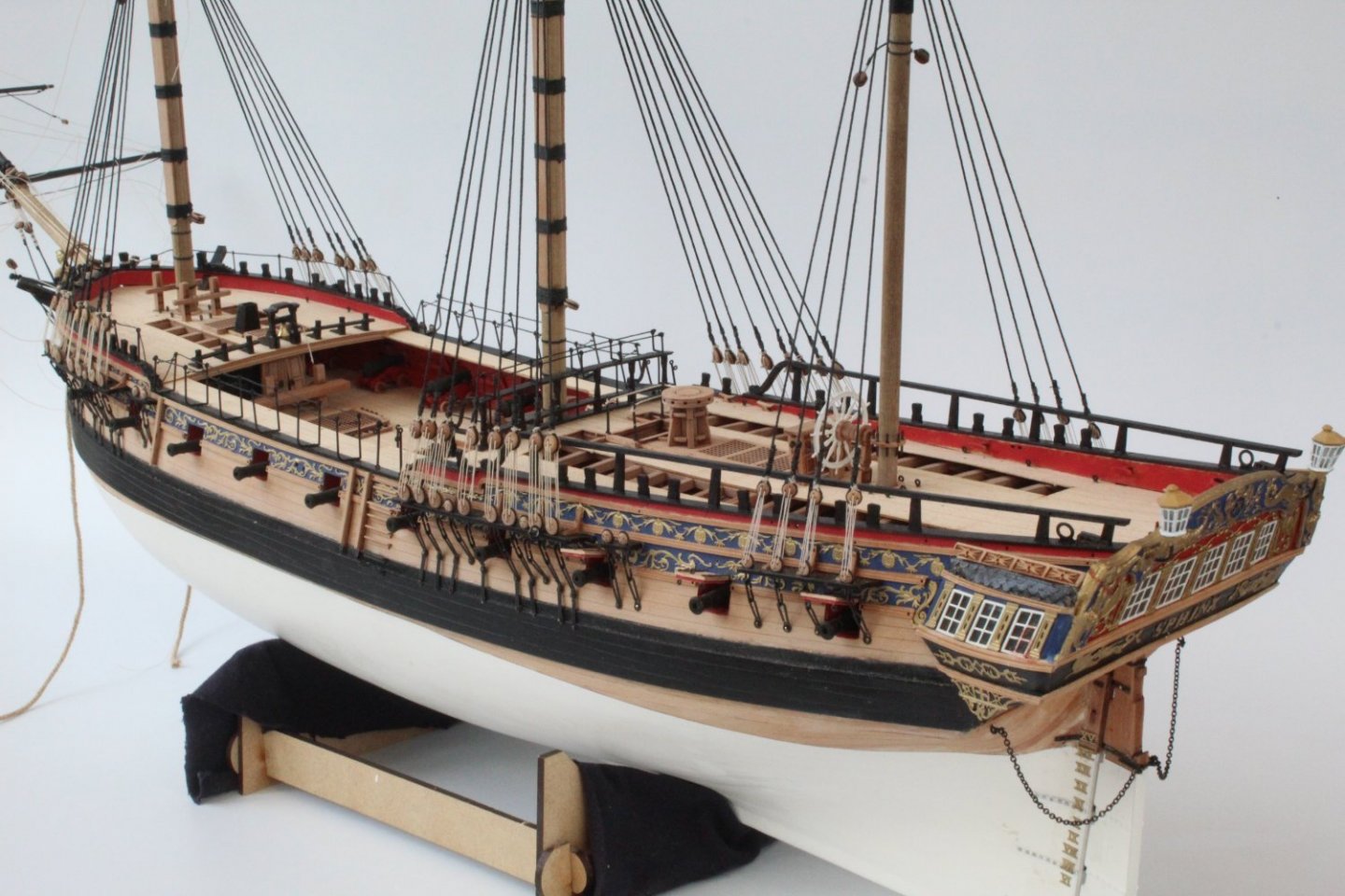
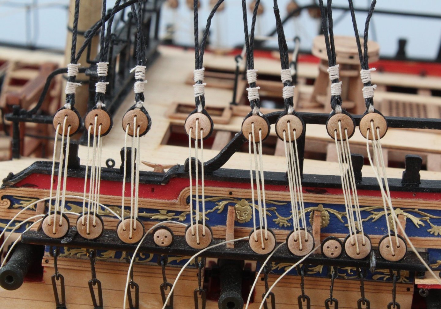
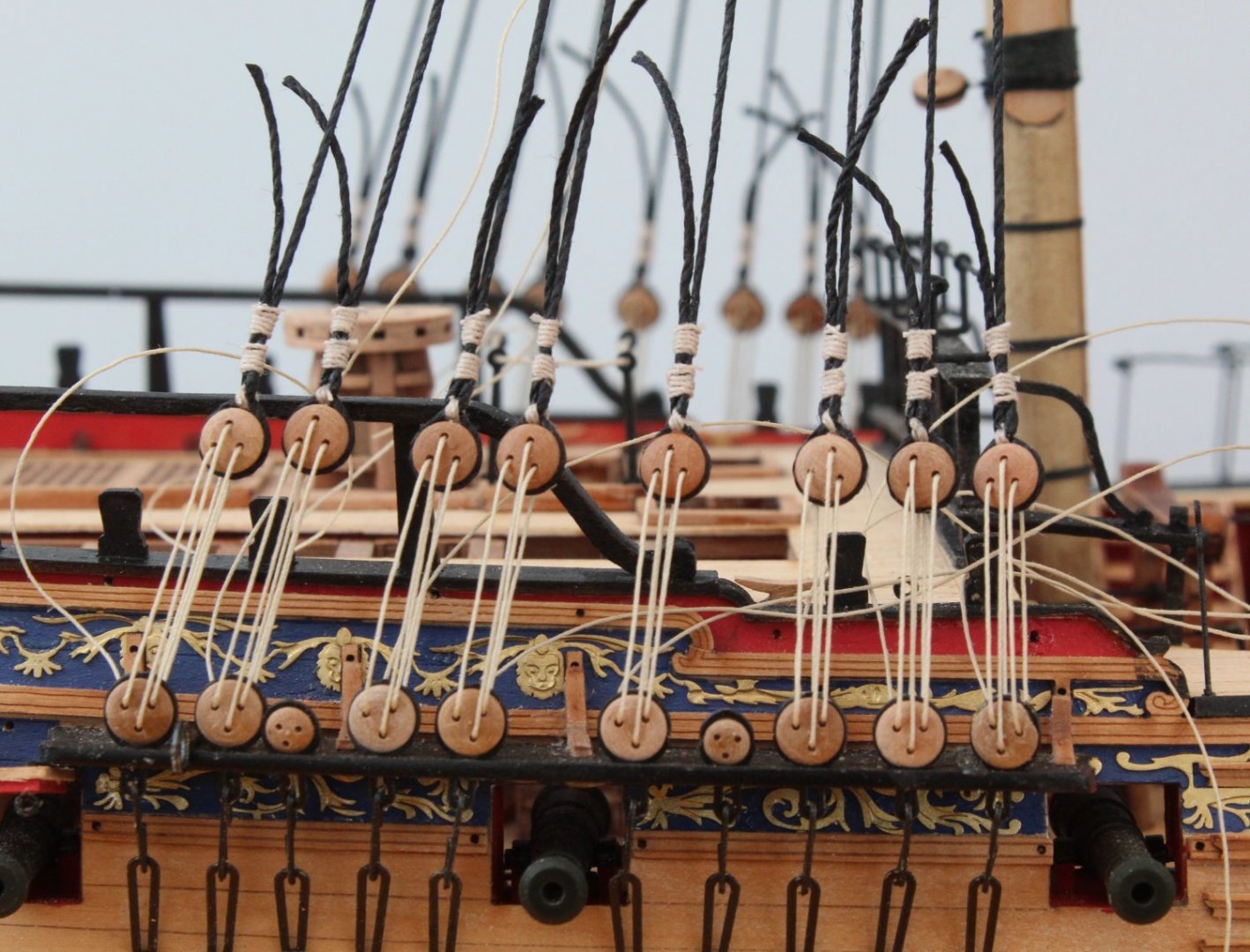
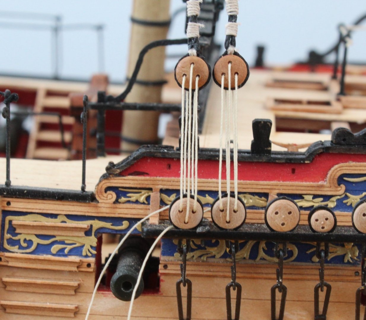
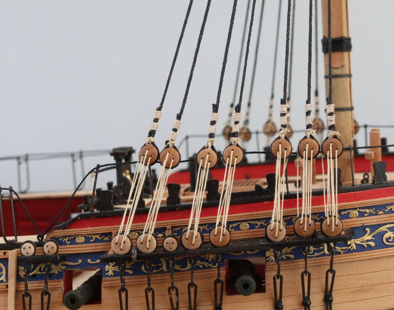
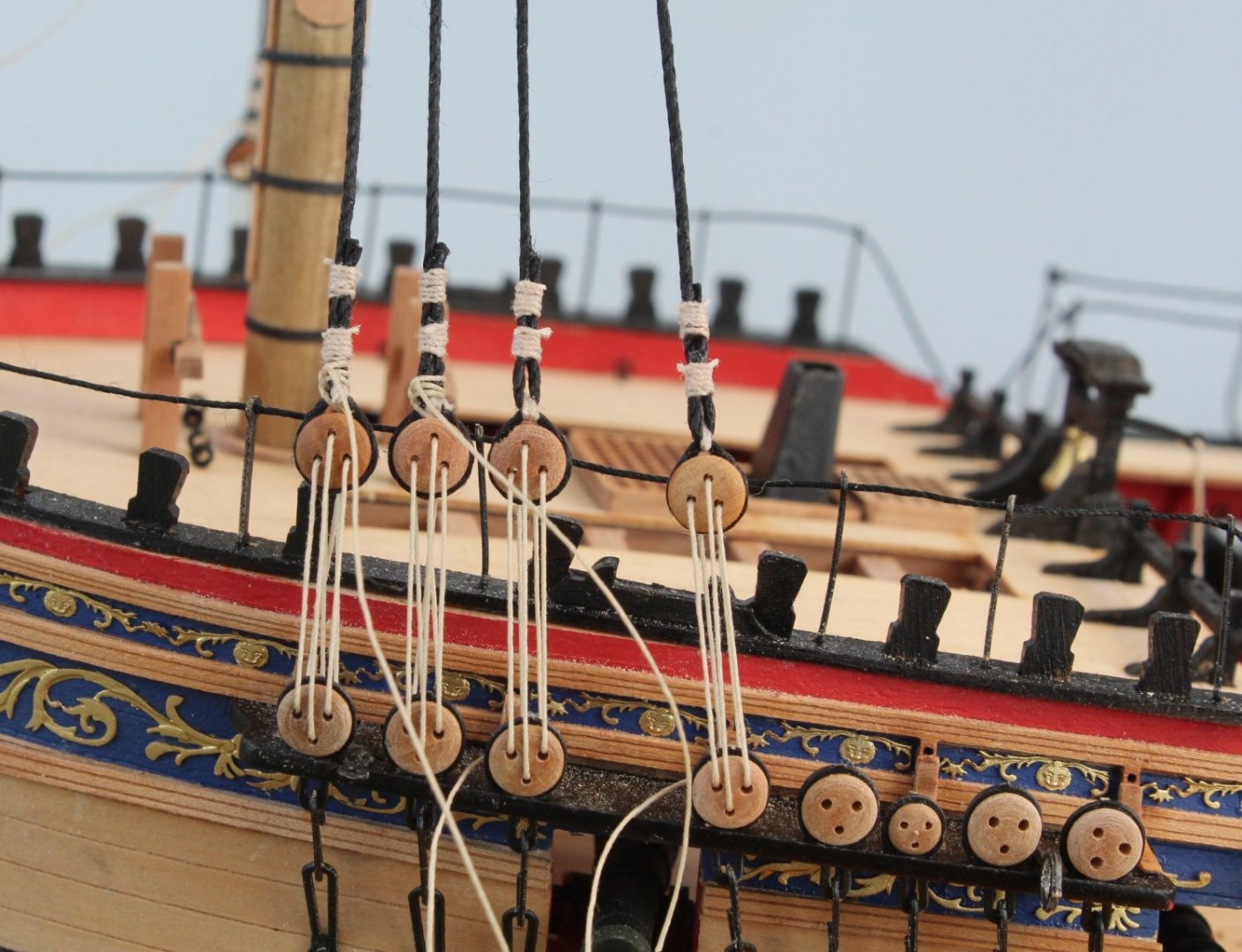
Mainmast Shrouds - Almost Complete Work is progressing very well on the mainmast shrouds. All the port side shrouds have been installed, the lanyards just need tying off and the shroud ends trimmed back. As can be seen in the photo below the shroud deadeyes are almost level with each other, the seizing's could have been a bit more consistent however, but once I have tweaked them a bit and dyed them black with Indian ink I think they will be acceptable. All the starboard side shrouds have also been installed and like the port side the lanyards just need tying off and the shroud ends trimmed back. As can be seen in the photo below they are a bit more uneven compared with the port side. Hopefully I can even them up a bit more by adjusting the lanyards when I tie them off. Shroud Rigging Video's Although I am not equipped to make decent video's of my work I have recorded the process I am now using for the main mast shrouds. I split the process into 4 different video's and they was recorded as I was adding the third shroud pair to the starboard side. These videos have been upload to my YouTube channel. There is no audio commentary on the video therefore I have provided a description of each video's content (along with the hyperlink to the videos) in the following text. Please be aware that I am not very good at making video's but it was fun to have a go. Creating The Loop Video This video shows me creating the loop in the shroud and then adding the deadeye to it. I have noted the video the loop is slightly out of focus, sorry about that. The start of the video shows the shroud line positioned and held in place with the quad hands, one quad hand is for the loop with another quad hand to hold the shroud tail in place. A 20cm length of 0.1mm natural thread is used to secure the loop in place with three half hitch knots placed on the top side of the loop. Once the loop has been formed the shroud line is removed from the quad hands and the loop is closed up as the deadeye is inserted. With the deadeye securely held in the loop the excess seizing thread is trimmed, but not flush with the knots at this stage. I have not added any ca gel to the knots as yet. In the final part of this video the approximate position of the inserted deadeye is checked with the other shroud deadeyes. The shroud deadeye position can still be adjusted as the shroud thread can still slide through the seizing. Checking Deadeye Position with the Jig Video This video does not show a great of information. The video starts with the jig being placed on the channel deadeye using the bottom two locating pins. With the jig in place the shroud deadeye is then checked. When the shroud deadeye is in the correct position it can be placed over the upper two locating pins on the jig. This can be seen in the video. The next step, which was not recorded, some ca gel is applied to the loop knots and the excess thread trimmed. Seizing the Shroud Line Video The next stage in the process is to add the two seizing's to the shroud line, which is shown in this video. With the deadeye held in one of the quad hands a 20cm length of 0.1mm natural thread is used for the seizing. Starting with the lower seizing a half hitch knot is tied to the rear of the shroud line and it's position is checked using a piece of 2mm tape. As can be seen in the video the position of the knot is adjusted. Another half hitch is then tied to the front of the shroud. As the seizing moved slightly when adding the front half hitch knot it was rechecked with the tape and moved the seizing back to the correct position. It was then a case of adding 8 more half hitches, 4 to the rear and 4 to the front. A touch a ca gel was used to secure the last half hitch and the excess thread trimmed. The second seizing was a simply a repeat of the first. A 20cm length of natural thread was used for the seizing and once its initial position was checked using a piece of 2mm tape it was then a case of adding the sequence of front and rear half hitches, 10 in total. Adding the Lanyards Video This is the final video in this sequence. A 30cm length of 0.25mm natural thread is used for the lanyard. The lanyard thread is run through the different deadeye holes in sequence. Once the initial lanyard rigging is complete some tension applied to the shroud and the slack in the middle lanyard is taken up, this also takes the slack in the right-hand side lanyard. This is followed by taking the slack up in the left-hand side lanyard. After a couple of goes the new deadeye is sitting at approximately the same level of the other ones and the shroud and lanyard are nicely tensioned.
- 476 replies
-
- 13
-

-
-
- sphinx
- vanguard models
- (and 1 more)
-
Thanks very much. I am going slow and steady which is against my nature!
- 476 replies
-
- 3
-
-
- sphinx
- vanguard models
- (and 1 more)
-
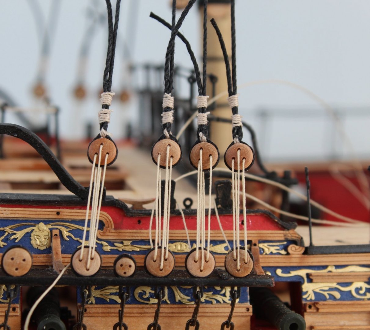
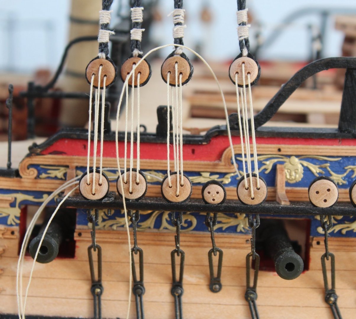
Foremast Shrouds - Work In Progress Now that I seem to have resolved a number of problems with my technique adding the foremast shrouds is coming together quite nicely. There is still plenty of room for improvement, but overall I am very pleased with how they are looking. It is slow progress. It seems to take between 20 to 30 minutes per shroud line to add the deadeye, set the position and to then add the seizing's and lanyards. I do not tend to spend as much time in the shipyard over the weekends so I expect I will complete the main mast shrouds either Sunday or more likely Monday next week. Towards the end of next week, once the mizzen mast shrouds have been added, I will start work on adding the catharpins. I have never managed to do a decent job adding catharpins on any of my previous builds but I will take my time and hopefully I will manage to get them added and looking OK. The first picture shows the first shroud pair on the port side. The lanyards have been added but have not been tided off as yet. The second picture shows the first shroud pair on the starboard side, the left-hand shroud deadeye will be rotated clockwise in the shroud loop a tad before the lanyards are tied off The third picture shows the first two shroud pairs on the starboard side. As can been seen the shroud deadeyes are almost at the level with each other. The forth picture shows the first two shroud pairs on the port side. I will try to adjust (or I will redo if necessary) the seizing's on the second pair as they do not look to good. Fingers crossed I can get away with just adjusting them. The fifth picture shows the first three shroud pairs on the port side and the 6 x shroud deadeyes are almost at the same level. I still have not adjusted the middle pair seizing's. The deadeye, second from the left does require a slight clockwise rotation in the shroud loop. The final picture is the current state of play of the Sphinx , sitting on the workbench waiting for the next shroud pair to be added to the starboard side.
- 476 replies
-
- 13
-
-
- sphinx
- vanguard models
- (and 1 more)
-
Allan. I am aware of serving machines and did build one last year as an experiment. I also considered buying one. Serving lines is something for the future, maybe trialing on a smaller build.
- 476 replies
-
- 5
-
-
- sphinx
- vanguard models
- (and 1 more)
-
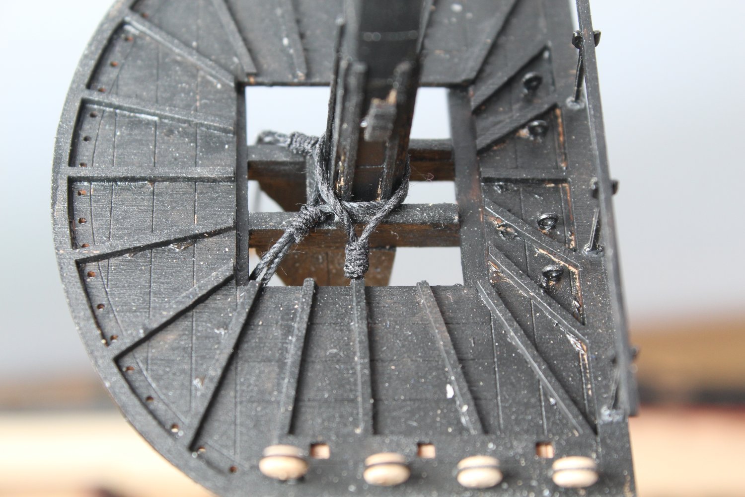
Mainmast Shrouds - a problem solved Through the trials and tribulations of adding the foremast shroud lines I was perplexed why I was unable to get the shroud deadeyes to looking even. I thought the methods I was employing were robust and should have resulted in a much better end result. I was determined to try to make the mainmast shroud deadeyes much more even. After adding the burton pendants to the mainmast I added the first shroud pair. The loops for the deadeyes were formed without any issues and the deadeyes were added. The jig was used to set the distance between the channel and shroud deadeye to 20mm on the first line. I then repeated the process for the second line and I was very pleased with the alignments. I then added the two seizing's above the shroud deadeyes. After I double checked the position of the shroud deadeyes with the jig I was very pleased with the how everything was looking. Next I added the lanyards to the first pair, initially everything looked good but after I started to apply a bit of tension I noticed the shroud deadeyes went not level. I was very perplexed considering all the checks I had made. I removed the lanyards and then rechecked the position of both shroud deadeyes with my jig. Neither deadeye would could be placed in the jig, the first deadeye was to high so would not reach the jigs locating pins and the second deadeye was to low. At first I was at a loss to understand what had happened but after a couple of minutes I knew what the problem was. It was the seizing of the shroud line at the top of the mainmast. The photo below shows the seizing which looks OK. What is happening is the shroud line can move through the seizing shown in the above photo, when tension is applied. This explains why I have ended up with one shroud deadeye being short and the other one on the shroud pair being to long. Now I know what the problem is I can take steps to prevent this happening.

- 476 replies
-
- 7
-
-
- sphinx
- vanguard models
- (and 1 more)
-
That is an option I would add
-
Hi Allan The kit provides all the different rigging threads. As with most kits there is no reference to serving shrouds, that is an option for the more talented builders who like to enhance the builds.
- 476 replies
-
- 3
-
-
- sphinx
- vanguard models
- (and 1 more)
-
Many thanks Dave for your very kind words, they are much appreciated. I am always striving to improve my skills so I can do these wonderful designs the justice they deserve. Glenn (UK)
- 476 replies
-
- 2
-
-
- sphinx
- vanguard models
- (and 1 more)
-
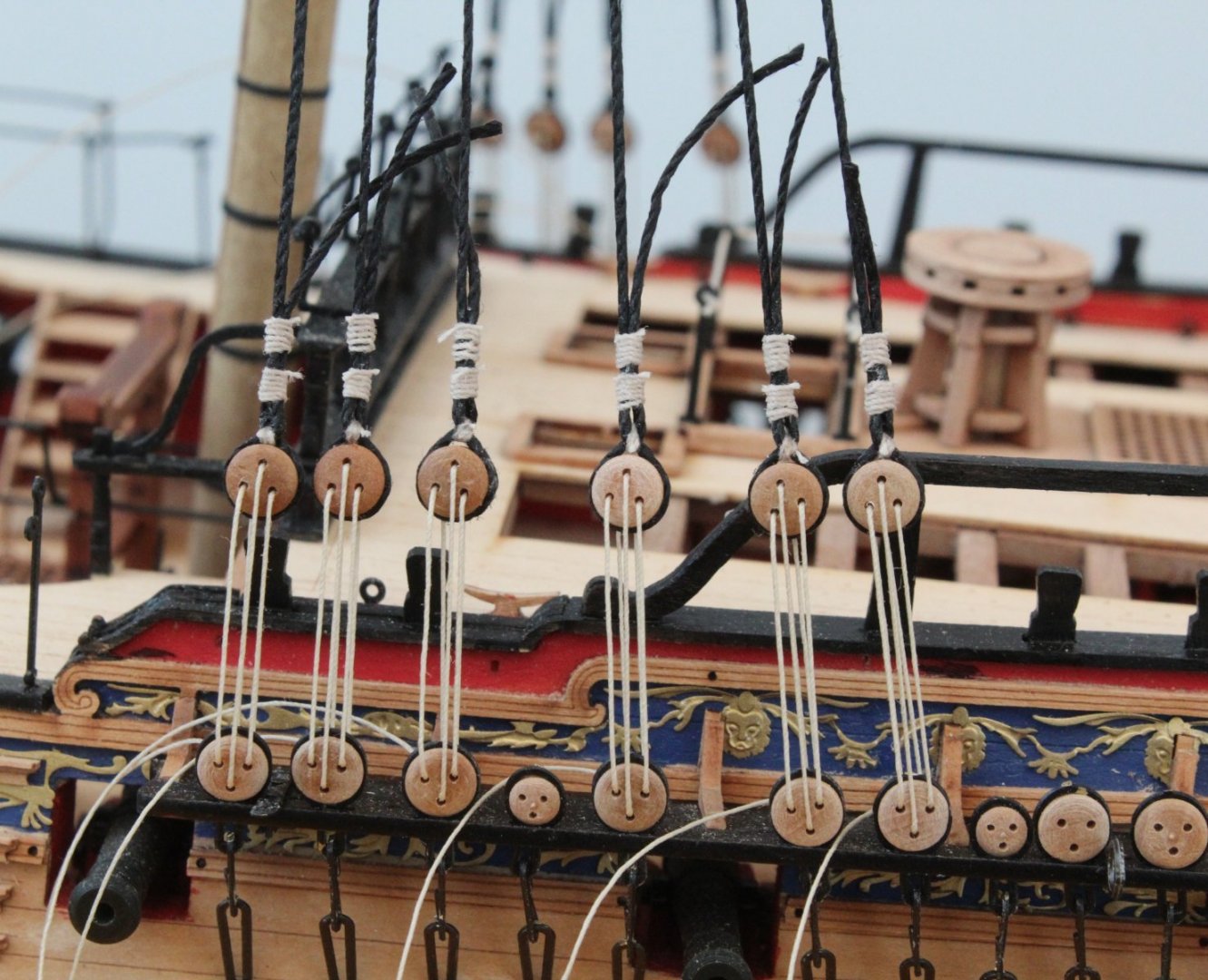
Foremast Shrouds - Complete I have finally completed adding the foremast shrouds at the third attempt. The shroud deadeyes are still a bit uneven but overall I am happy with how they are looking. My technique has improved immeasurably compared with my previous builds but there is still room for improvement. Hopefully the main mast shrouds will look even better. The seizing will look much better when they have been dyed black with Indian ink. They look a bit better when view from afar!
- 476 replies
-
- 6
-
-
- sphinx
- vanguard models
- (and 1 more)
-
Allan. I prefer to seize with a different coloured thread. Natural thread can be dyed black using Indian ink.
- 476 replies
-
- 2
-
-
- sphinx
- vanguard models
- (and 1 more)
-
Thank you, I spent ages debating if I start yet again. It is proving to be the right decision.
- 476 replies
-
- 2
-
-
- sphinx
- vanguard models
- (and 1 more)
-
Following on from my last post where I decided my foremast shrouds (take 2) were still not up to the required standard I had a light bulb moment when having the tea break. I recalled that @DelF used a similar jig to mine but his had two sets of pins set in a piece of wood. The top pair were used to hold the shroud deadeye and the lower pair was located in the channel deadeye. It was a simple task for me to add a second set of pins to my jig. I used the same method as detailed in my post for adding deadeyes to shrouds. I added an extra step after adding the deadeye to the shroud loop where I simply inverted the jig and then adjusted the position in the shroud line so the deadeye would located on the two pins. In the first two photos below the deadeye has been adjusted and is now located on the top jig two pins. With reference to the next photo the first two shroud lines have been set, the next shroud pair are currently work in progress, the lanyards have been adjusted and I'm much happy with how the shroud deadeyes look. They are still far from perfect but they are so much better than my previous two attempts. I might dye the top two shroud seizing's with some black Indian ink

- 476 replies
-
- 9
-
-
- sphinx
- vanguard models
- (and 1 more)
-
I will watch Jim's build with great interest.