HOLIDAY DONATION DRIVE - SUPPORT MSW - DO YOUR PART TO KEEP THIS GREAT FORUM GOING! (83 donations so far out of 49,000 members - C'mon guys!)
×


Glenn-UK
-
Posts
3,162 -
Joined
-
Last visited
Content Type
Profiles
Forums
Gallery
Events
Everything posted by Glenn-UK
-
 Looks nice, you are making an amazing boat
- 345 replies
-
- 1
-

-
- Duchess Of Kingston
- Vanguard Models
- (and 1 more)
-
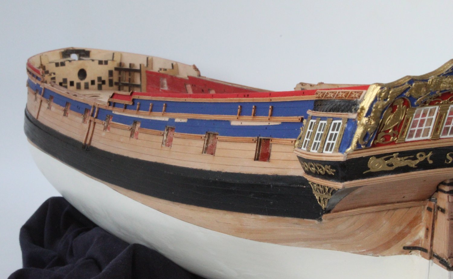
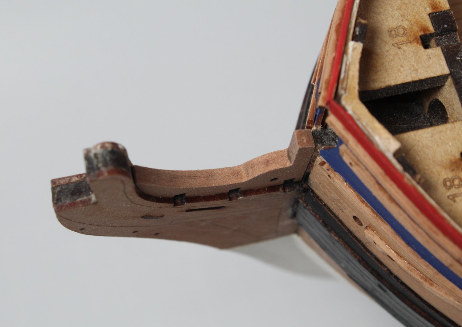
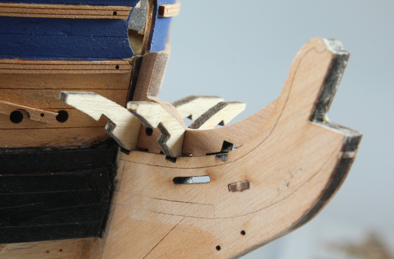
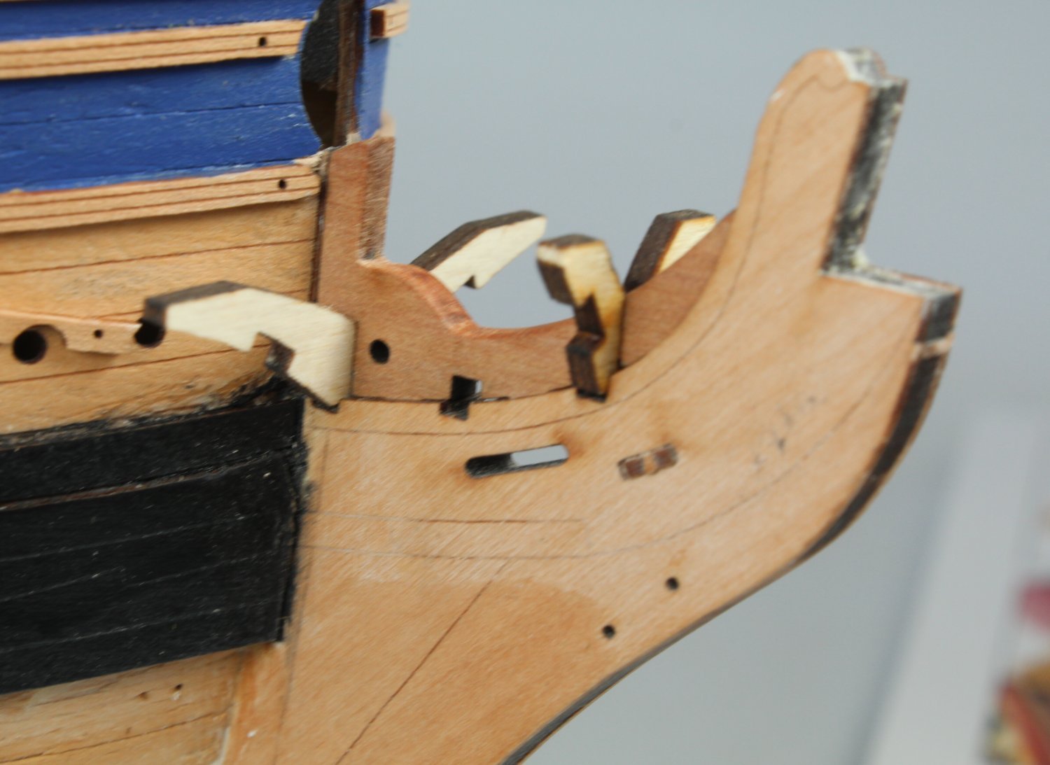
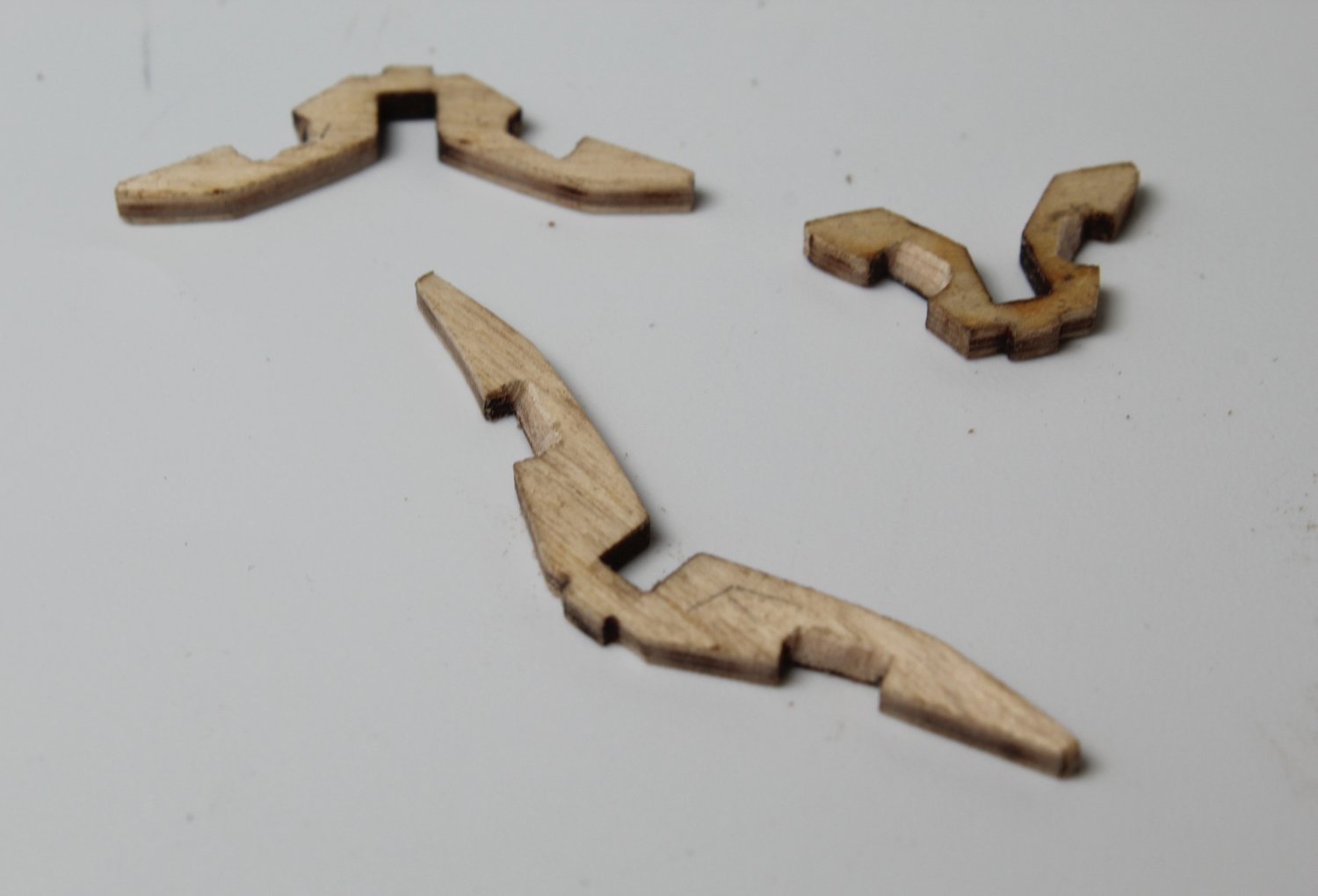
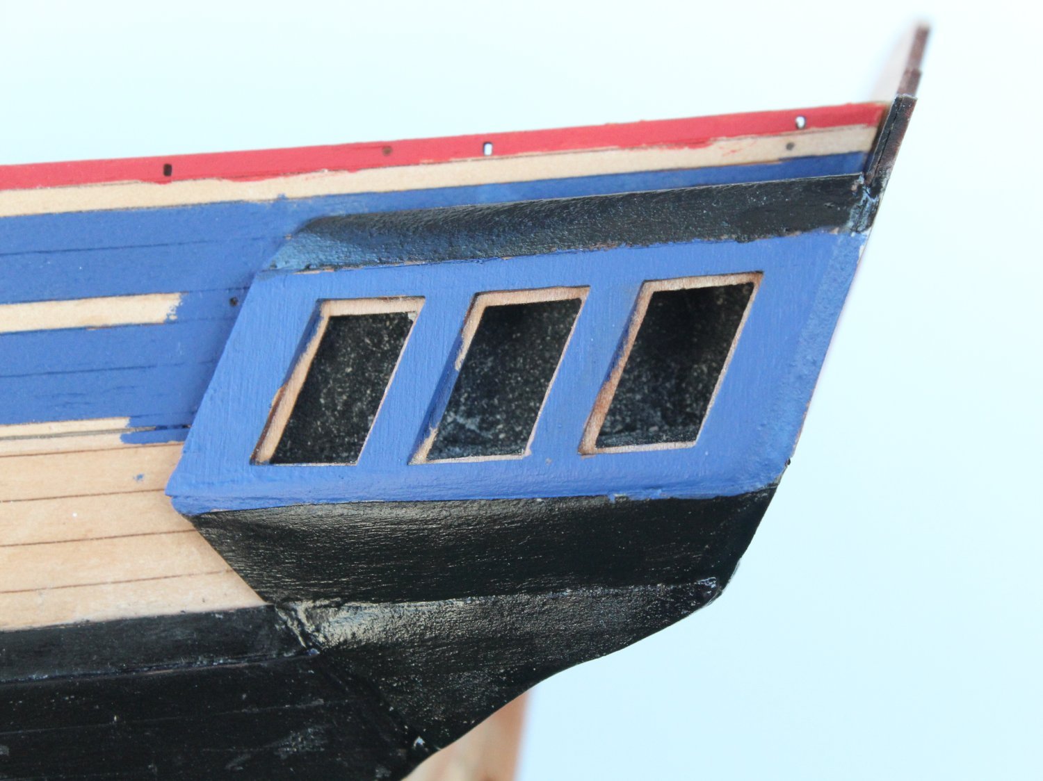
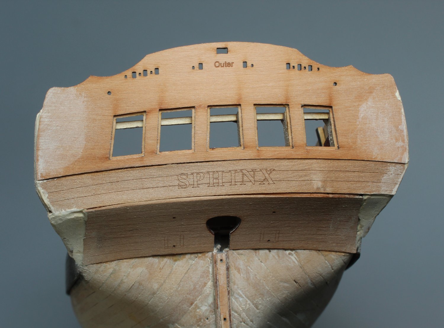
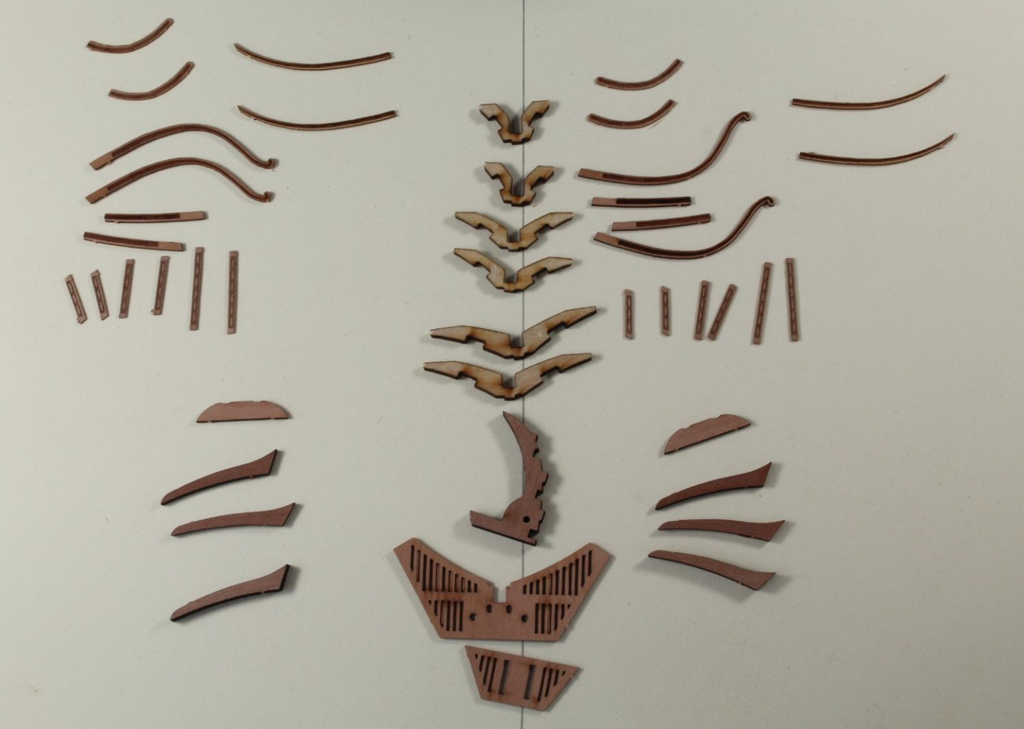
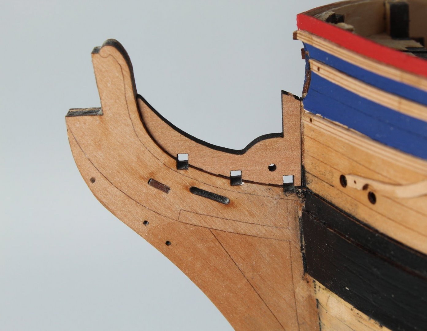
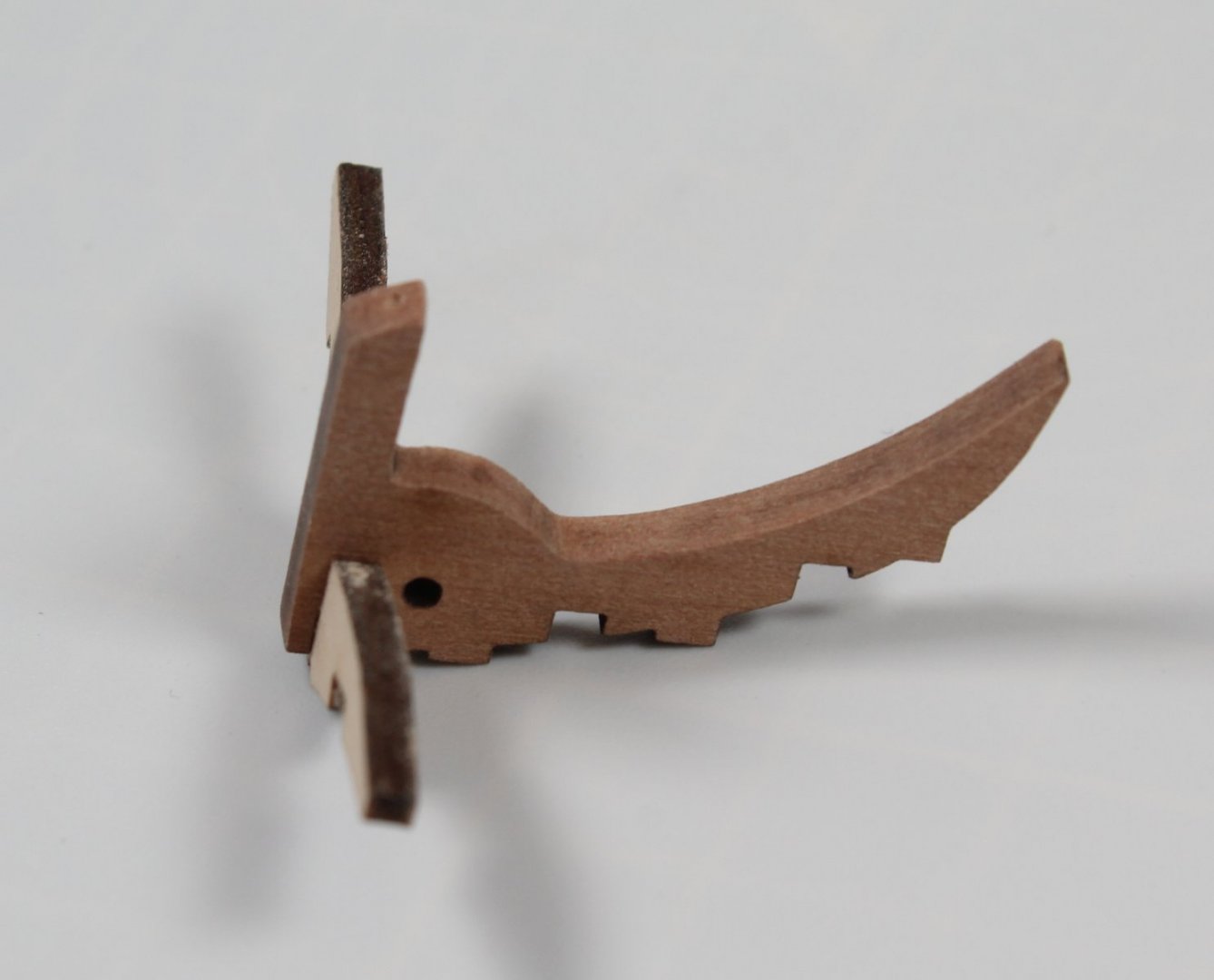
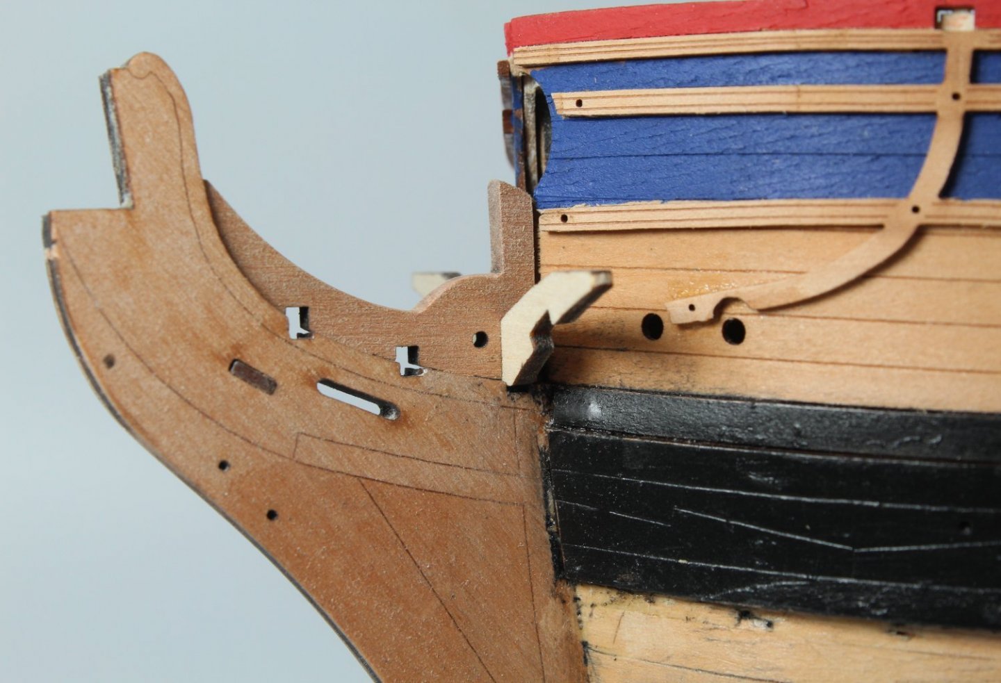
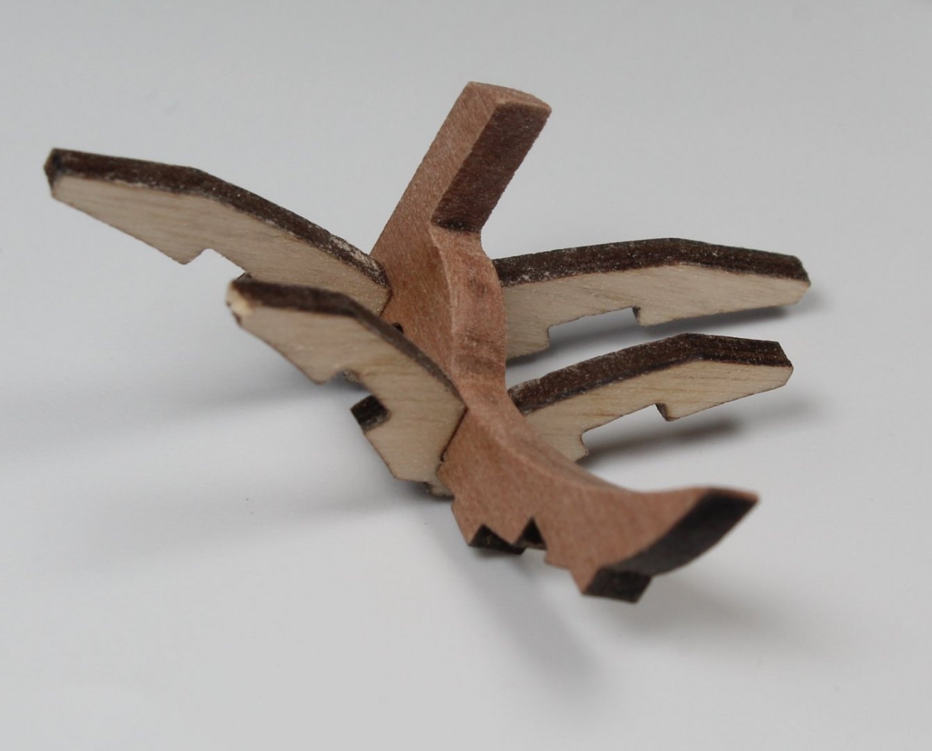
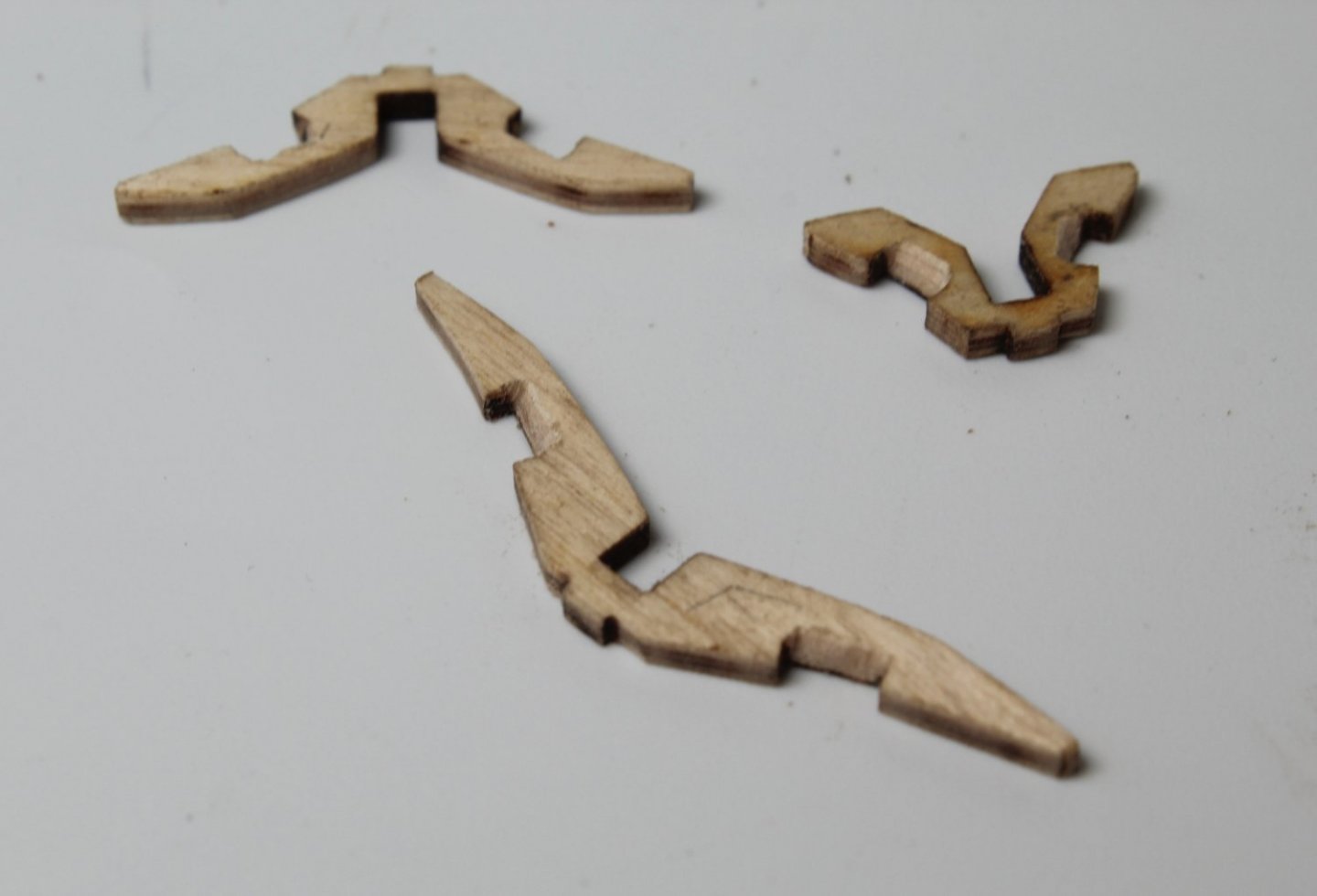
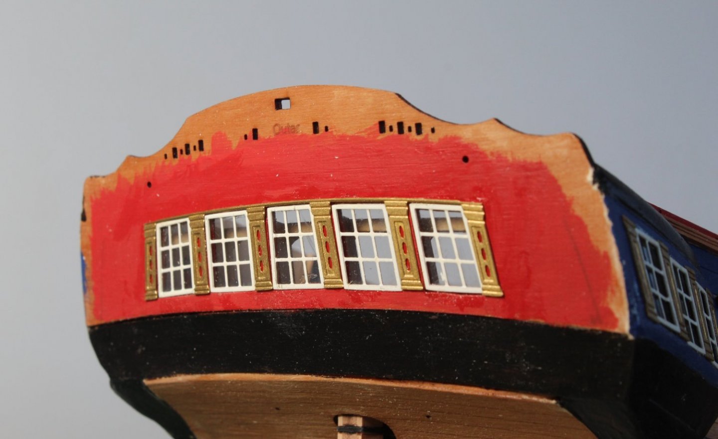
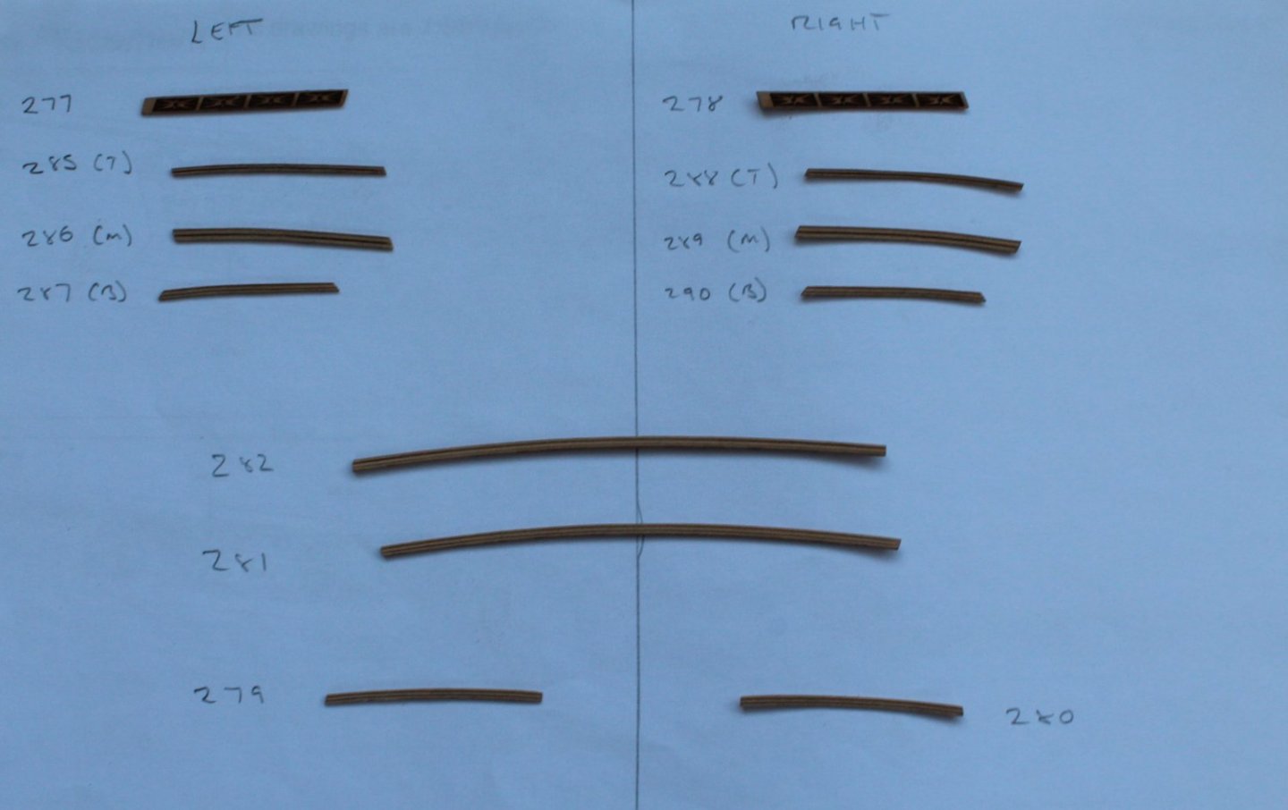
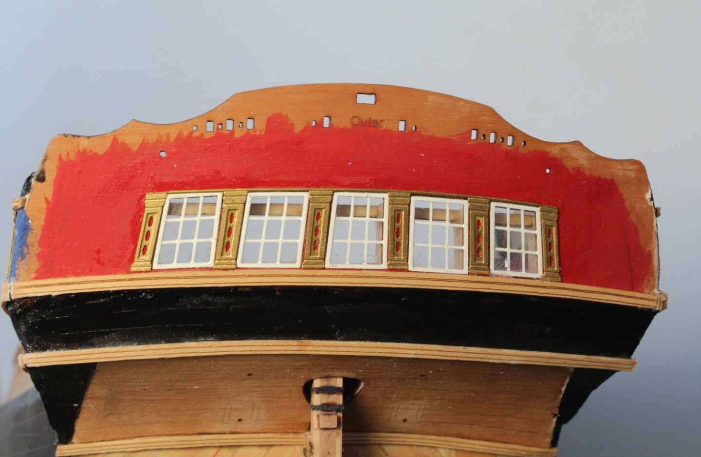
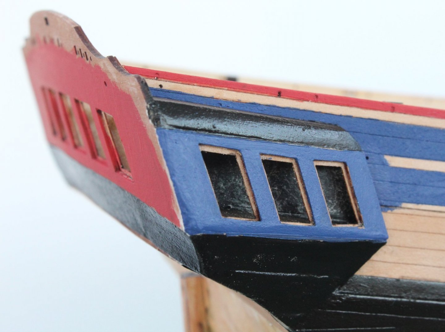
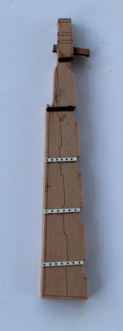
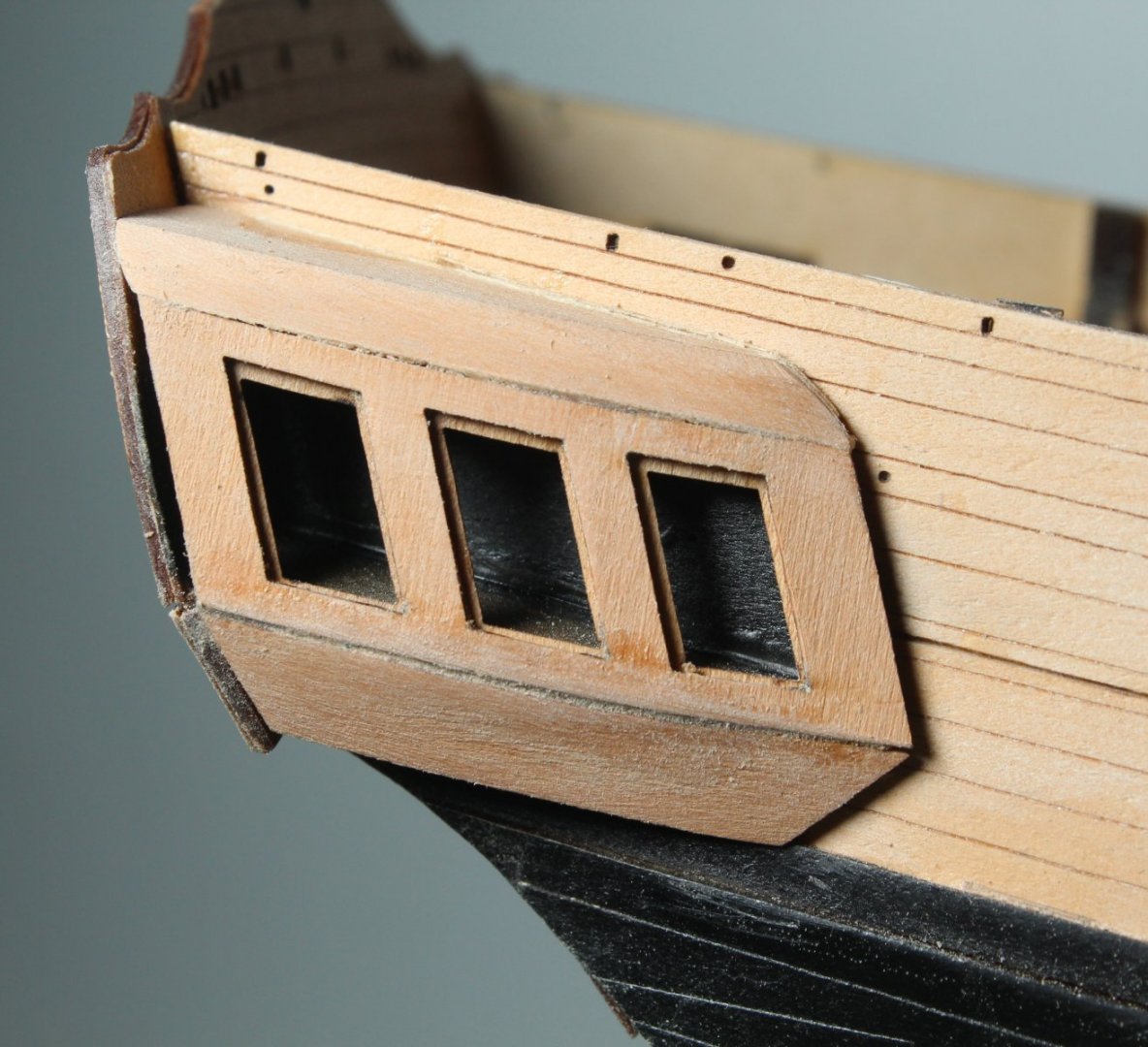
Stern Fascia I have now completed work on the stern fascia. It is not perfect by any stretch of the imagination but compared with my V1 build it is a marked improvement and I am very happy with how it has turned out this time around. I am aware I still need to fit the following items: a) gun port hinges to the upper stern counter panel b) two eyebolts on lower stern rail c) rudder chain between the spectacle plate and lower stern rail eyebolts These will be fitted later on in the build process Bow Area I have now started work on the bow detail. I thought I would detail the process I go through in this respect. I began by using the build manual to identify the parts required and I remove the required parts from the various sheets. The parts, when removed are, placed on a sheet of card. I placed a centre line on a piece of card, so the various left and right-handed parts are kept apart. I have also removed the various spare parts that have been supplied. I took the gammoning knee and checked the fit, and as can be seen in the photo below it looks to be a good fit. The laser char was removed from the visible edges of the gammoning knee. Next I took the largest bow v-pattern and checked the fit with the gammoning knee. The bow v-pattern did require a little bit of sanding so it fully locate in the slot on the gammoning knee. The dry fitted assembly was once again dry fitted to the hull to ensure the two parts were properly aligned. The above process was then repeated for the middle bow v-pattern. It was not a perfect fit in the photo below but I have sorted this out. Finally I repeated the process for the smallest bow v-pattern. The bow v-pattern slots for the for the bow lower rails were then tapered to approx. 45 degrees. The laser char was also removed. Tomorrow I will start the assembly process in earnest.


- 476 replies
-
- 13
-

-
- sphinx
- vanguard models
- (and 1 more)
-
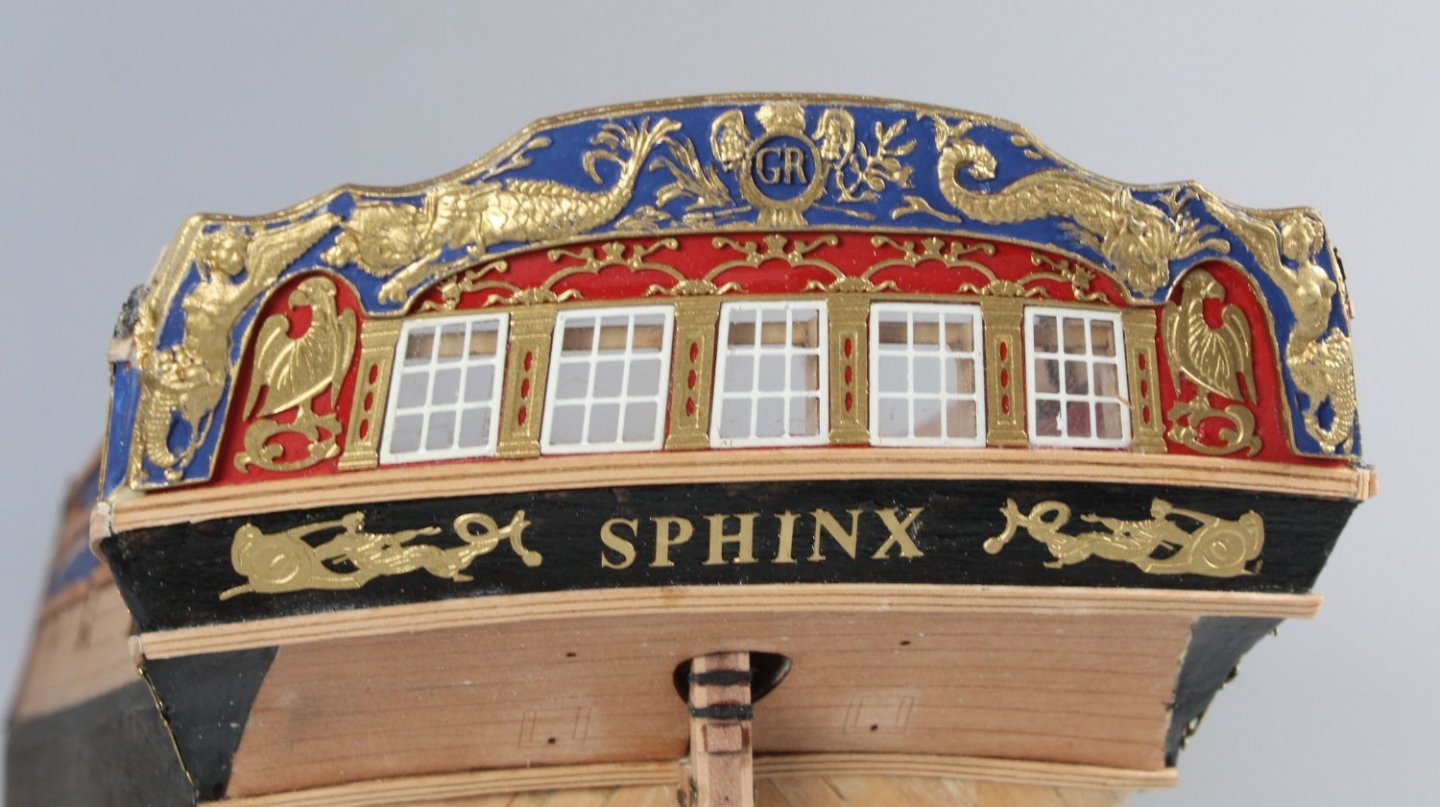
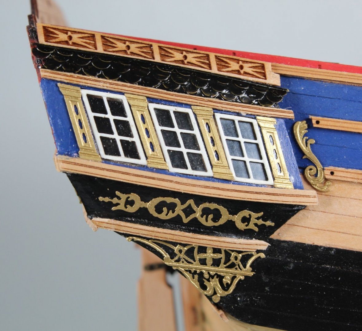
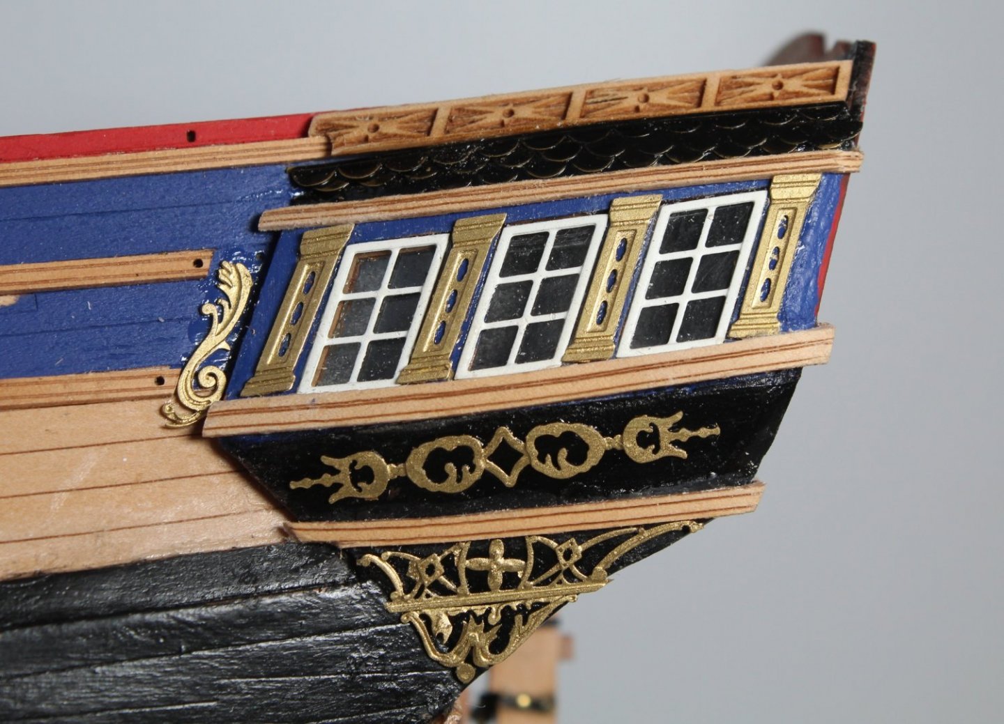
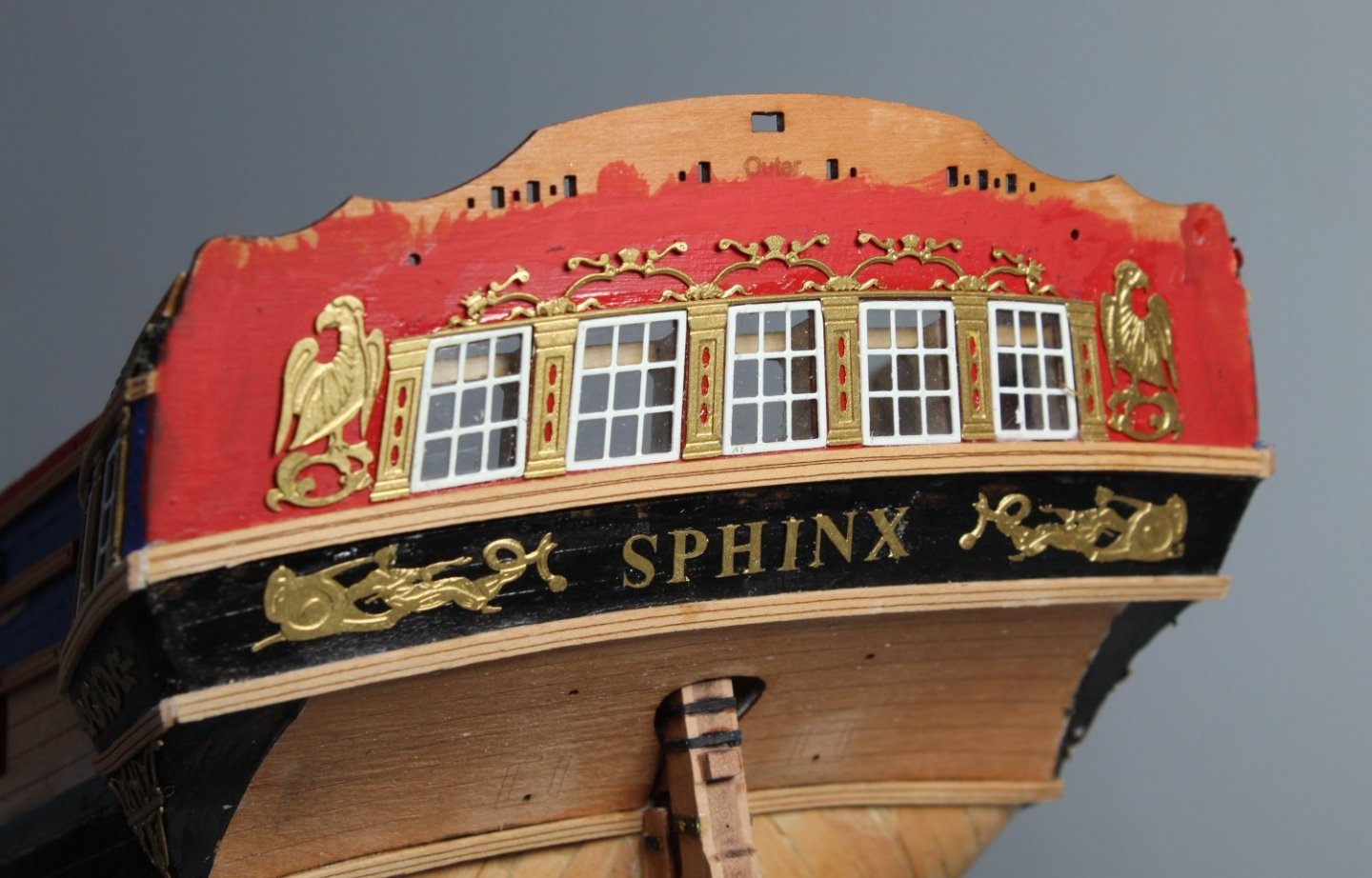
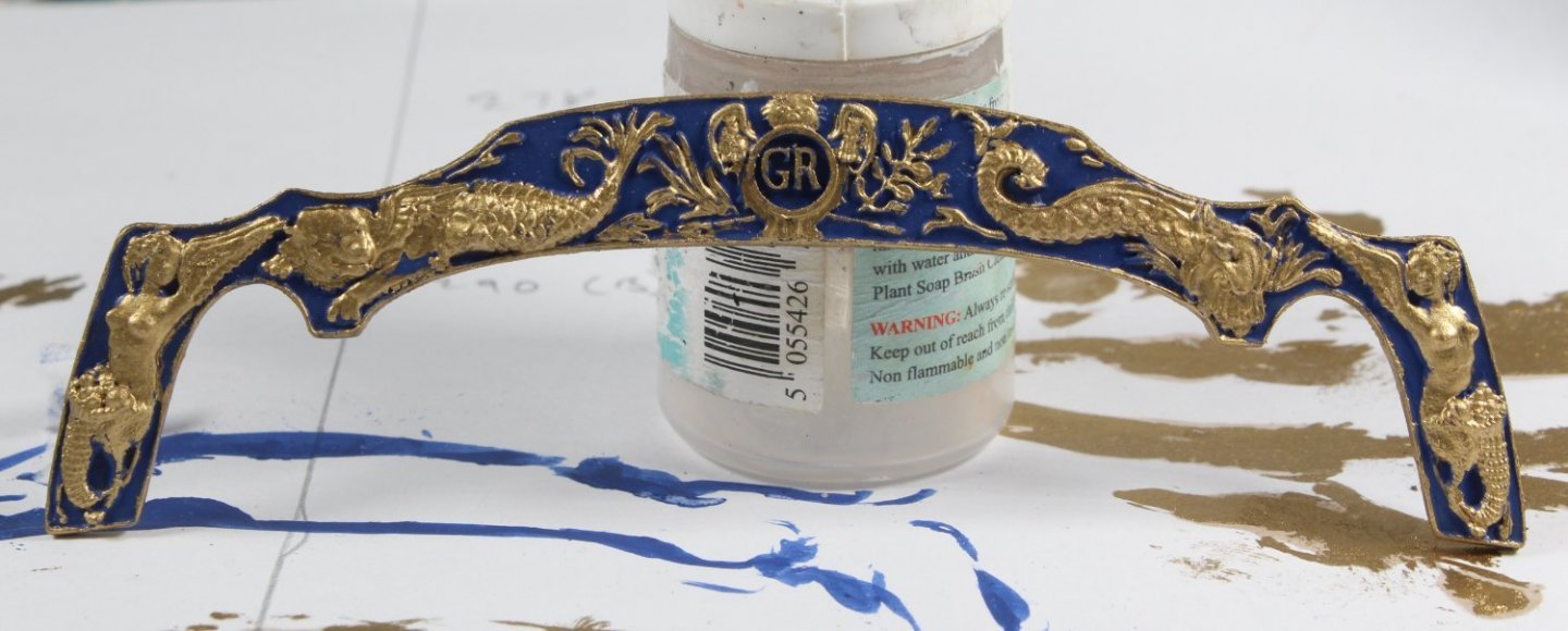
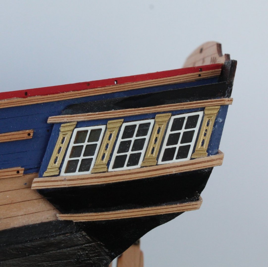
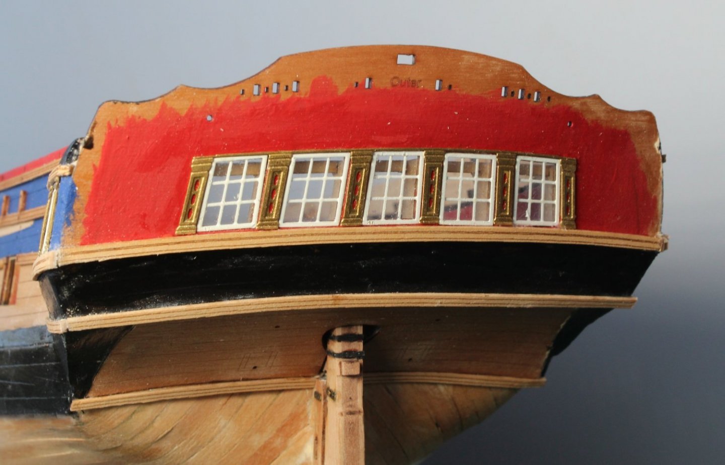
Quarter Galleries Today I have added the final parts on the quarter galleries and the task is now complete. The PE decorations were painted gold last night and secured in place on the quarter galleries using super phatic glue. The upper finishing tile roof PE decorations have also been fitted, but they were painted black. Finally the quarter gallery upper fretwork patterns were glued in place using super phatic. Stern Fascia I have also nearly completed all the work on the outer face of the stern fascia. The PE parts have been painted gold and secured using super phatic glue. I will need to touch up some of the black and red paint, as can been seen in the photo below. The resin moulding has been painted, but still requires a bit more work to tidy up the painting up before I will go ahead and fix it to the stern fascia pattern.
- 476 replies
-
- 11
-
-
- sphinx
- vanguard models
- (and 1 more)
-
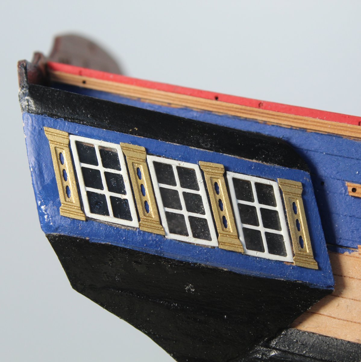
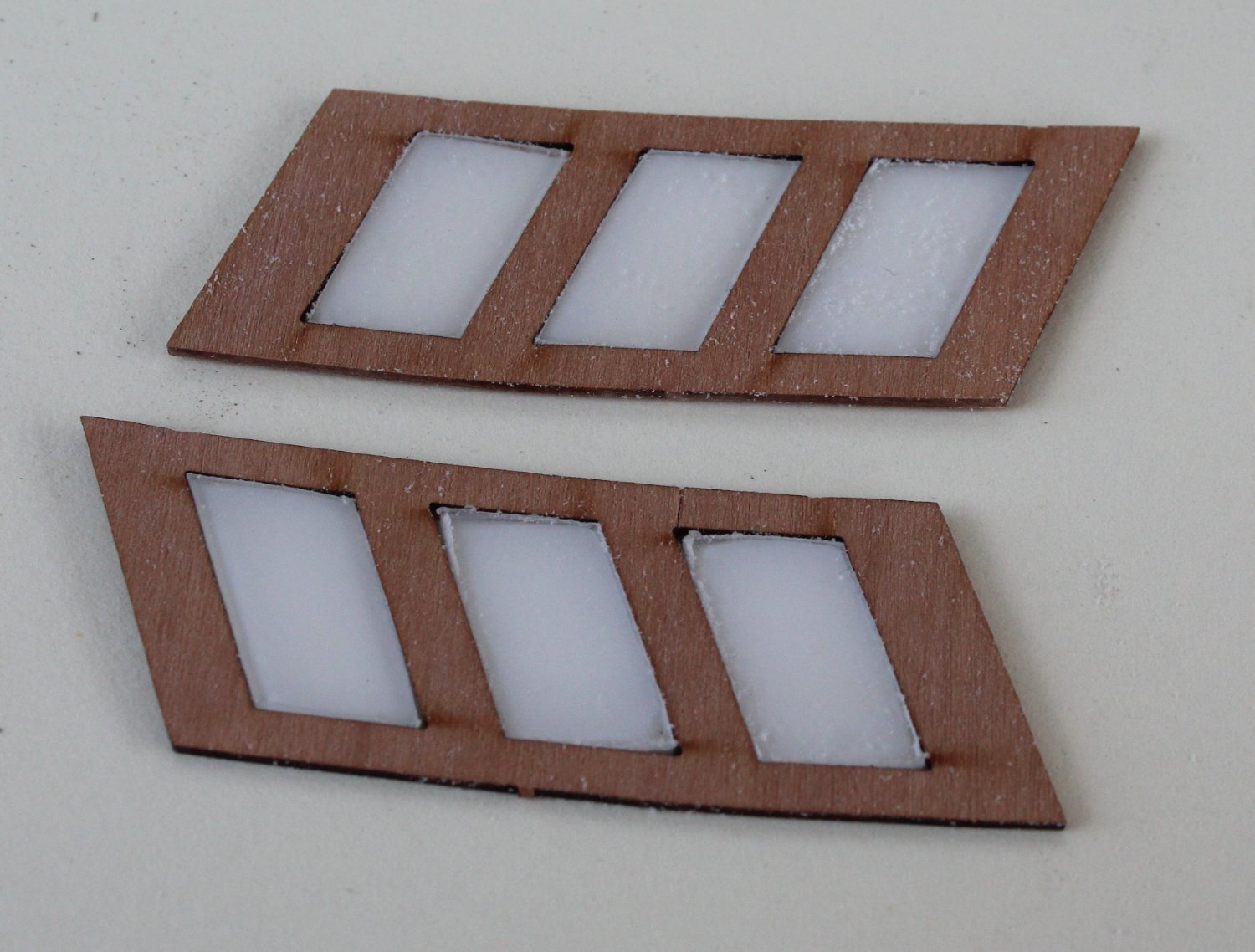
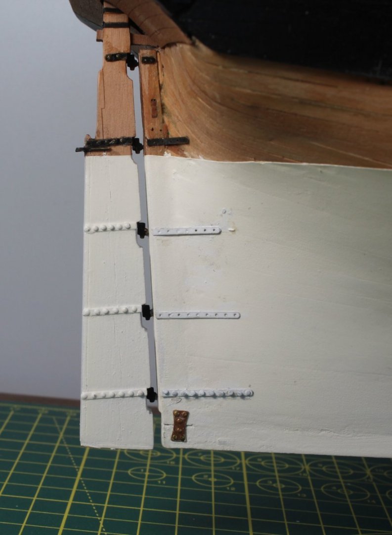
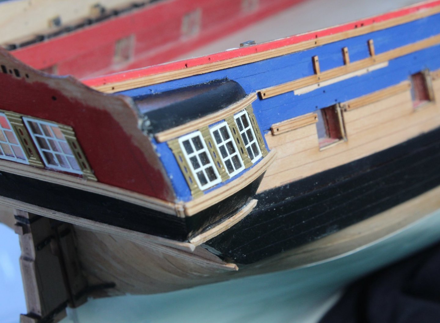
Working on Quarter Galleries and Stern Fascia The completed rudder assembly was fixed in place without any problem. I also added the Rudder Brace Straps to the hull. I have not added all the cut off brass pins to the Rudder Brace Straps but I will be doing so in the fullness of time. As can be seen in the photo below I have added the pin heads to the lower Rudder Brace Straps. The window panes were fitted to the frames, using super phatic glue. The window frames were primed and painted white (two coats applied). The frames were then added to the quarter galleries and stern fascia, using super phatic glue. Next the Stern Column Panel and the Quarter Gallery Vertical Columns were removed from the PE sheets, cleaned and painted gold. Once the paint had dried the parts were glued in position, again using super phatic. The right-hand side quarter gallery The stern fascia The next task was to fit decorative rails to the stern fascia and quarter galleries. I started by removing the laser char from the edges of the rails and once that was done the parts were ready to be fitted. I carefully laid the parts out in insure I was fitting the right parts. I opted to use ca gel to secure the rails. For the most part it was a fairly straightforward task to complete. I did end up having to remove the stern fascia upper rail and quarter gallery middle rail as I incorrectly positioned the stern fascia rail. I has set it to low but thankfully I noticed the problem and thankfully the rails were removed without any damage. I am reasonably happy that the stern fascia rails are nicely aligned with the quarter gallery rails. I am a bit unhappy with the position of some of the Quarter Gallery Vertical Columns but I have decided to leave them as shown in the photo's below. This is a photo of the left-hand side quarter gallery, the paint will require a little bit of touching up. The two end Quarter Gallery Vertical Columns parts look bad in the close up photo, but for me it was much more important to get the rails to align with the stern fascia rails. This is a view of the right-hand quarter gallery, and if you look carefully you will notice that I had to add a small filler piece to the top stern fascia rail

- 476 replies
-
- 9
-

-
-
- sphinx
- vanguard models
- (and 1 more)
-
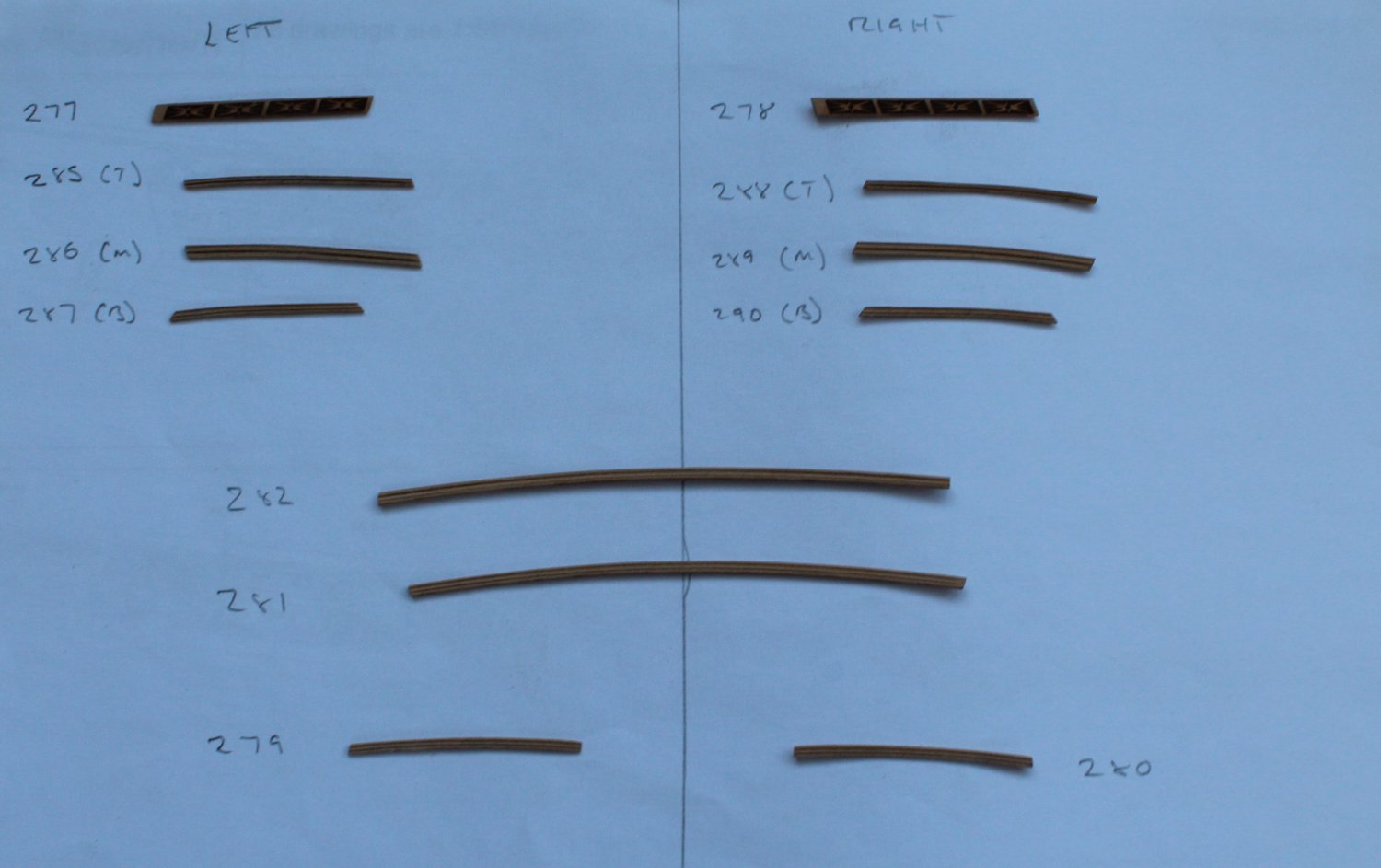
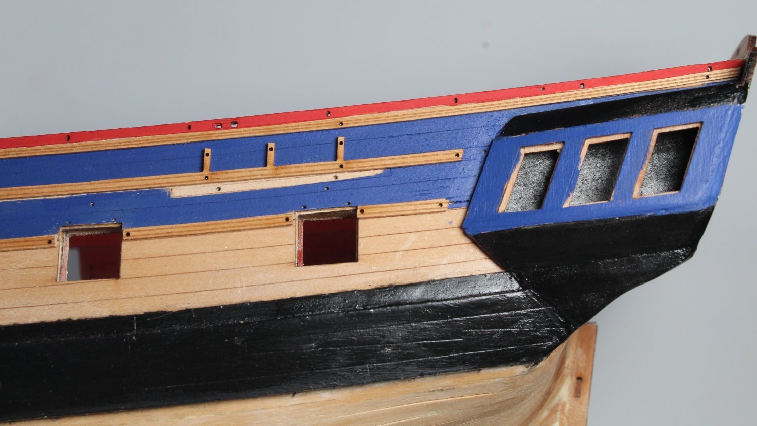
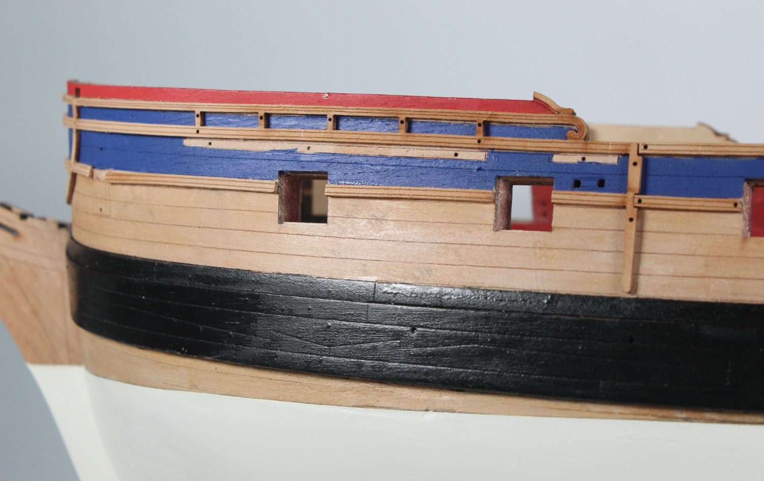
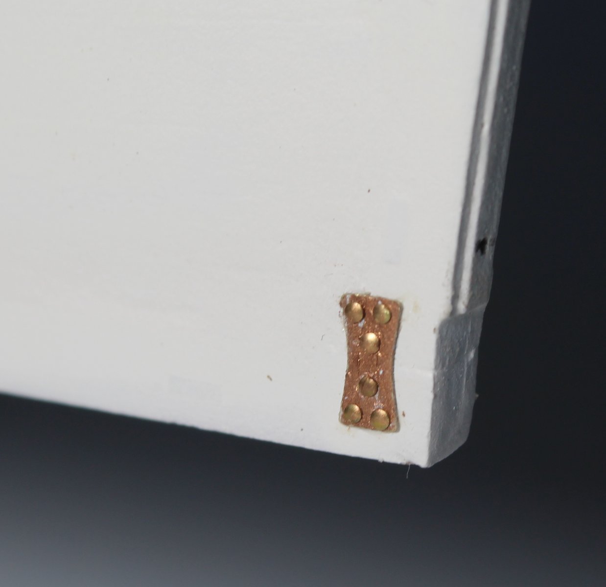
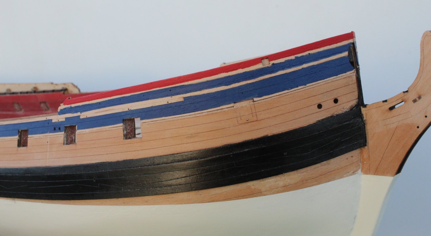
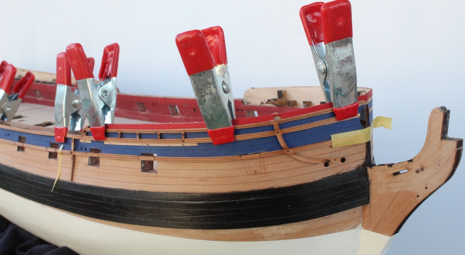
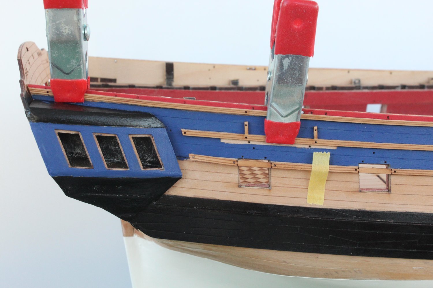
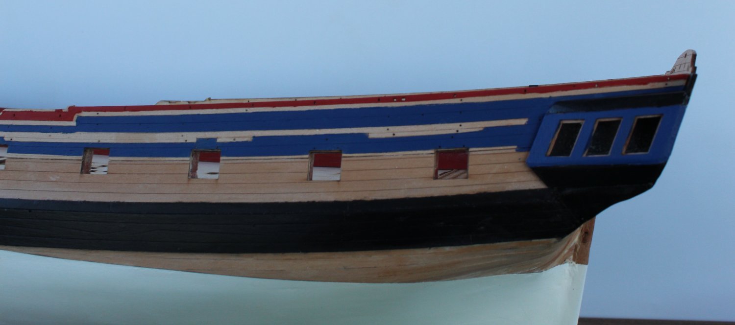
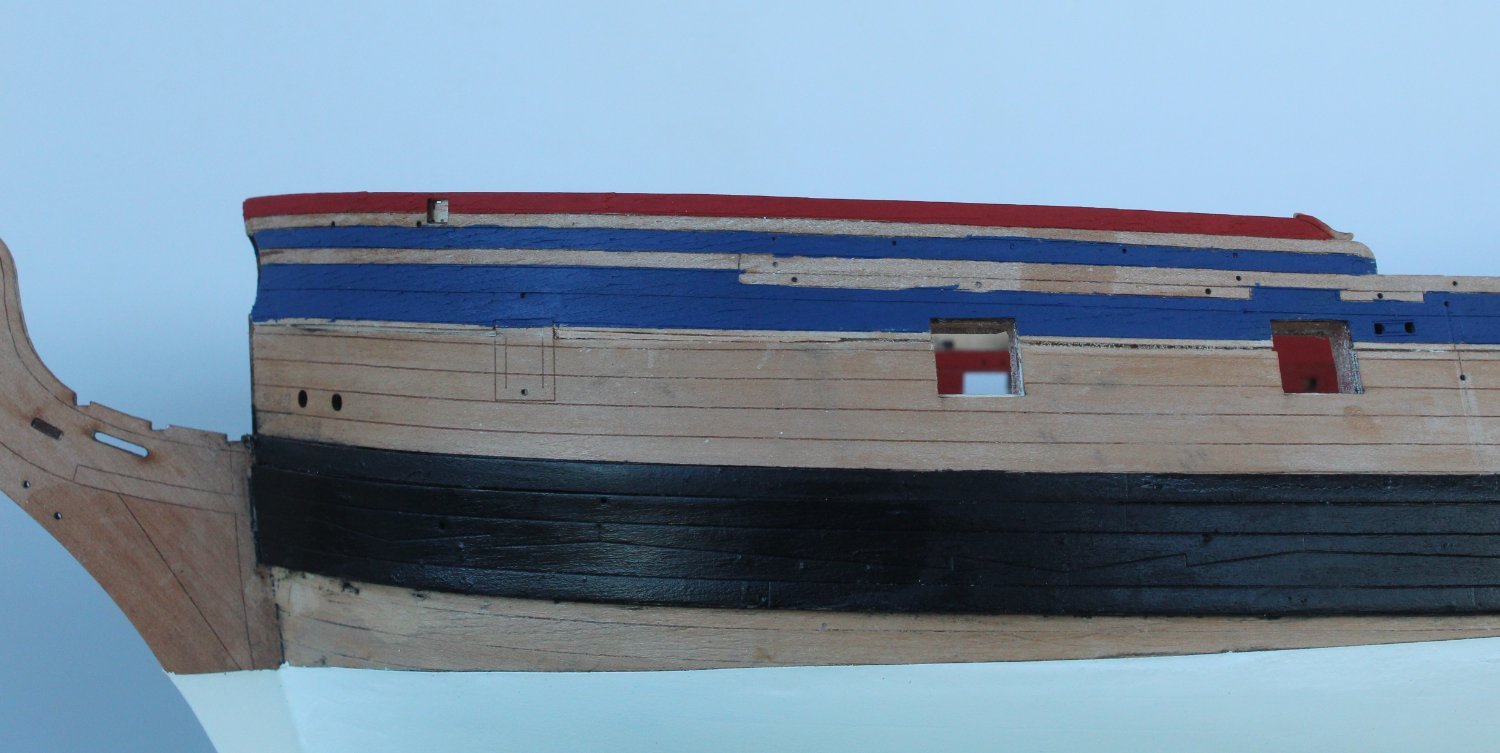
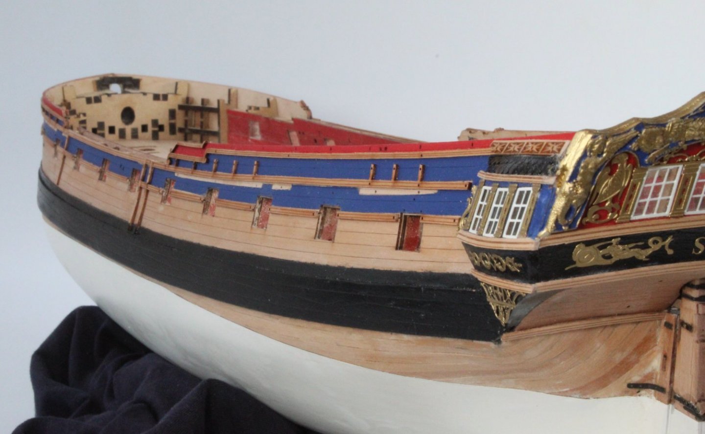
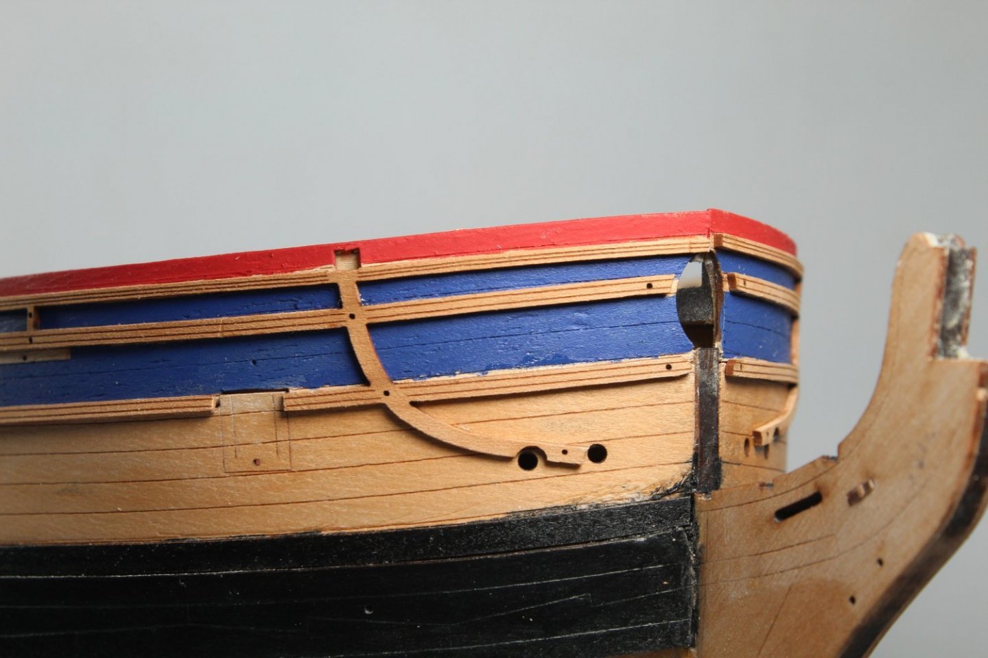
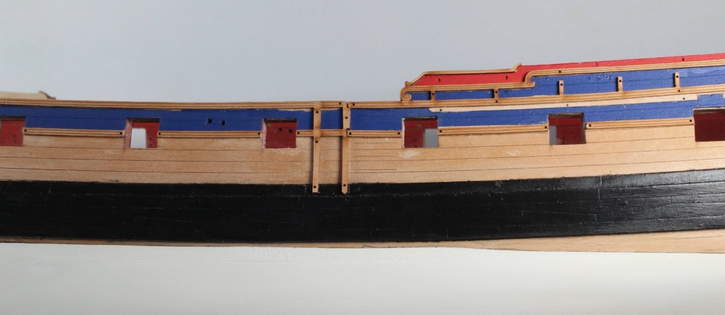
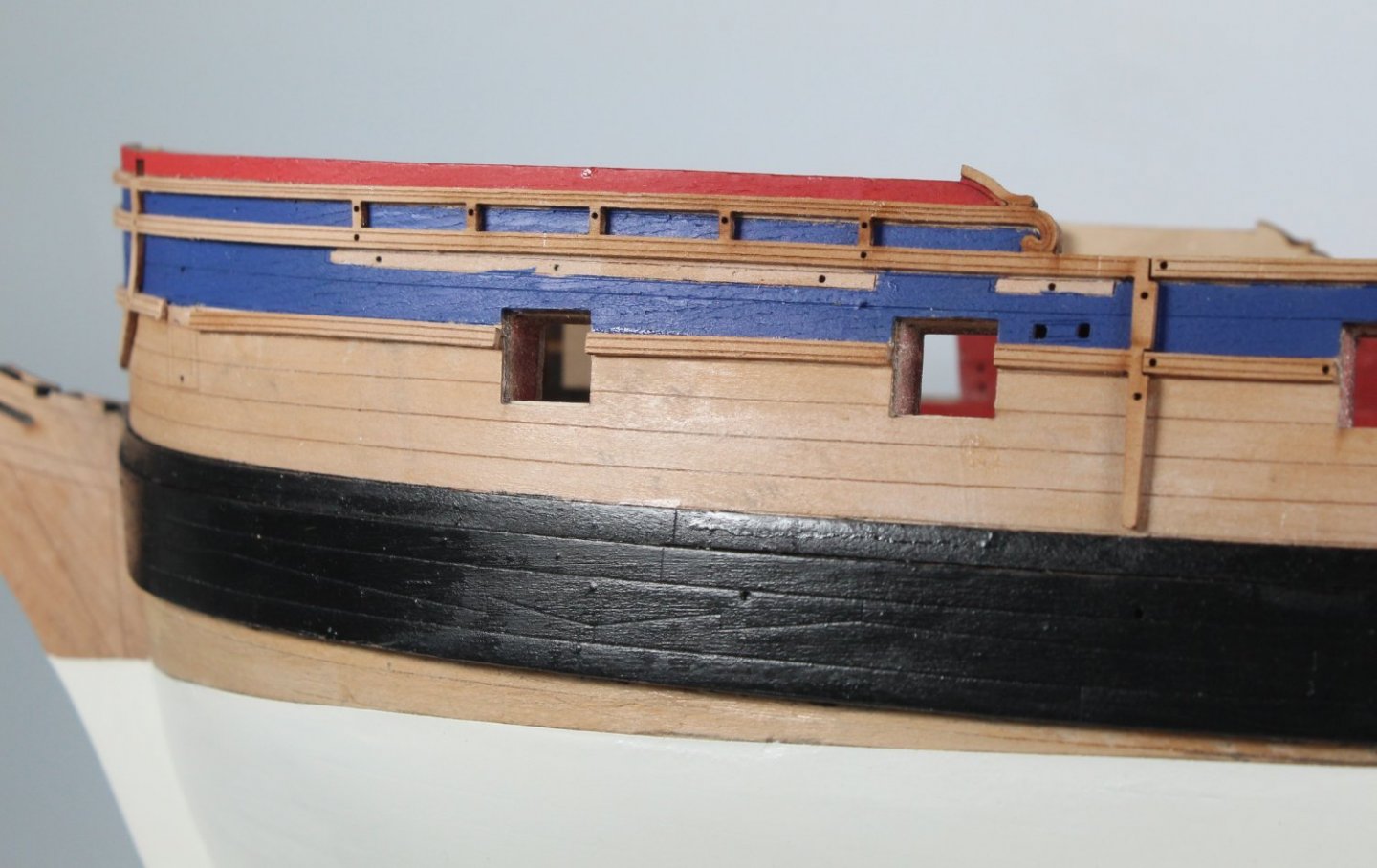
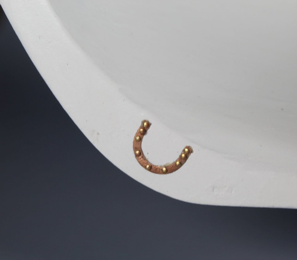
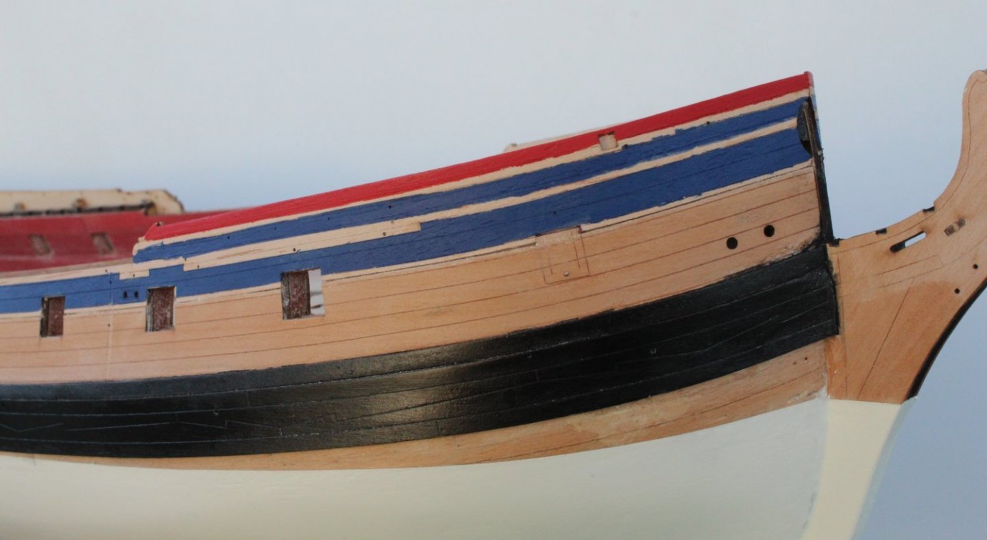
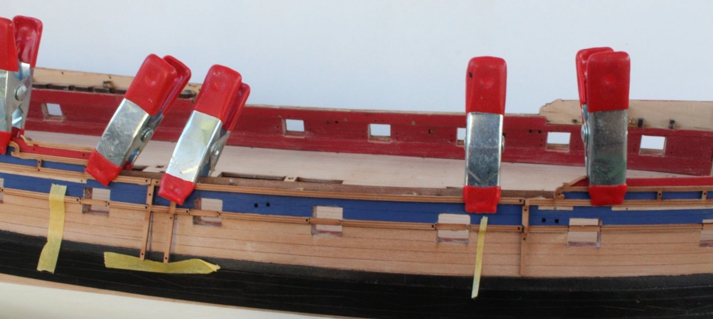
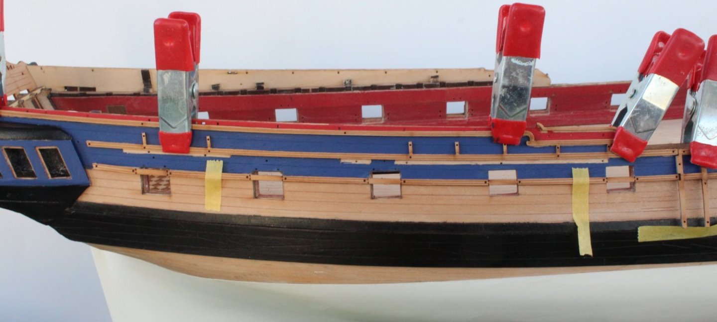
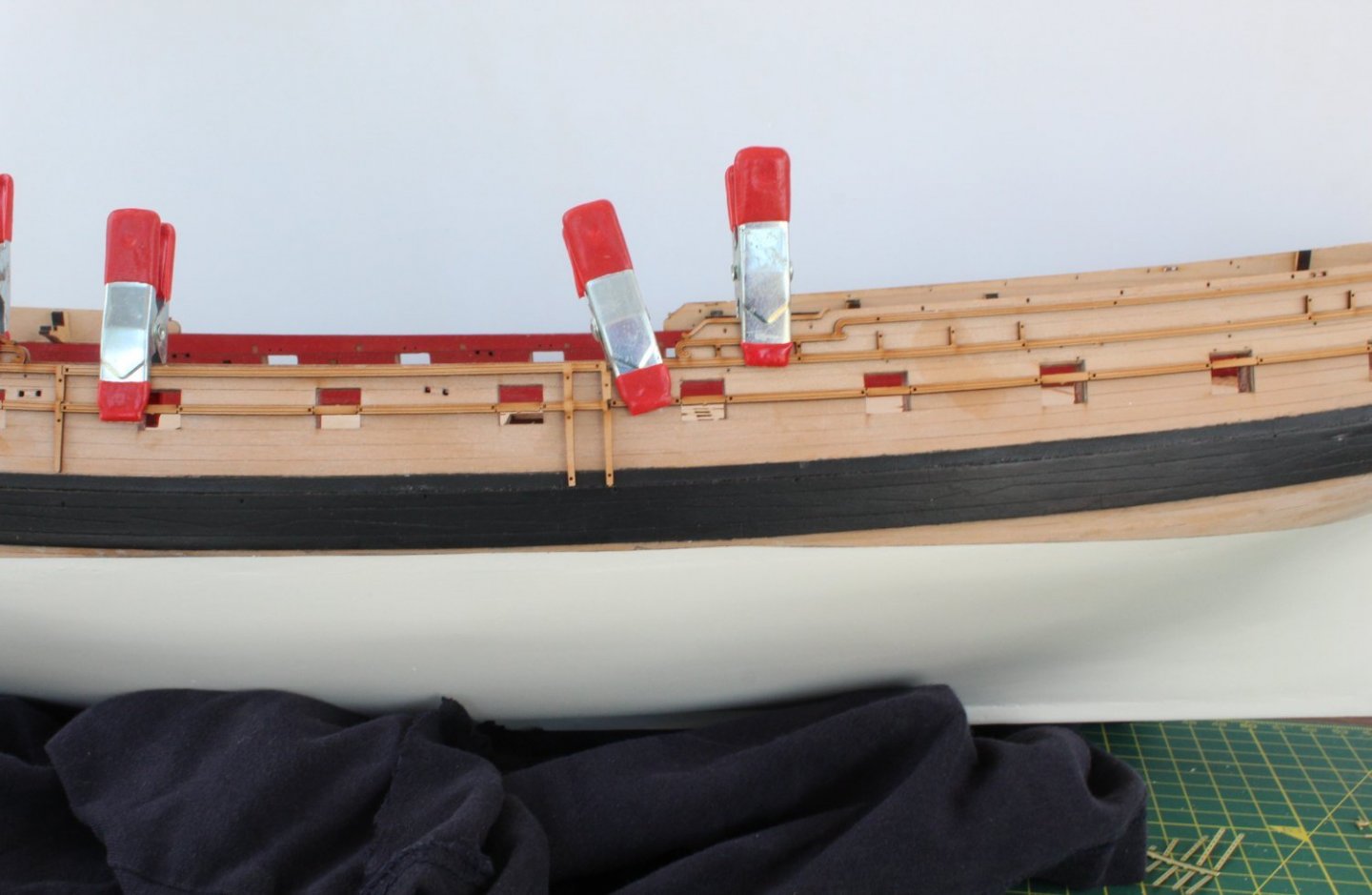
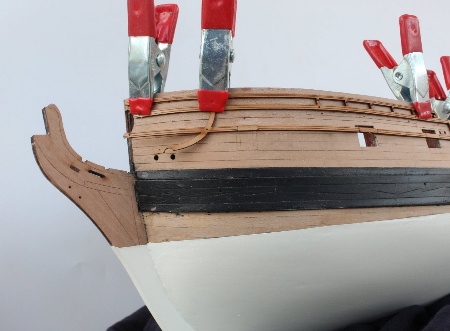
Hull Plates and Rails The horseshoe and fishplates have been fitted to the hull. I used super phatic glue to secure the parts and brass pins to ensure they were properly aligned. Once the glue had cured I added shortened brass pins to all the holes. Horseshoe Plate Fish Plate. I will touch up the copper painting. All the rails have now been fitted. The left and right bow rails were soaked in hot water for 20 mins and then clamped to hull and left overnight to dry. I opted to remove the excess rail material that sat across the gun ports before fitting. I brushed super phatic glue to the rail parts and then carefully fitted them to the hull. The glue gripped really well as each rail part was added. I did make a slight error with the fitting sequence on the right-hand side, but it does not look too bad. It would have been better to fit the stern and bow rails first before adding the midship rails. I need touch up the odd bit of blue paint with a very fine tipped paint brush. I do need to paint the tips of the two vertical strips black to match the wales. The end of the curve rail sits a bit low but once the hawse holes have been opened up to 2mm and the other items added it will look Ok.


- 476 replies
-
- 12
-
-
- sphinx
- vanguard models
- (and 1 more)
-
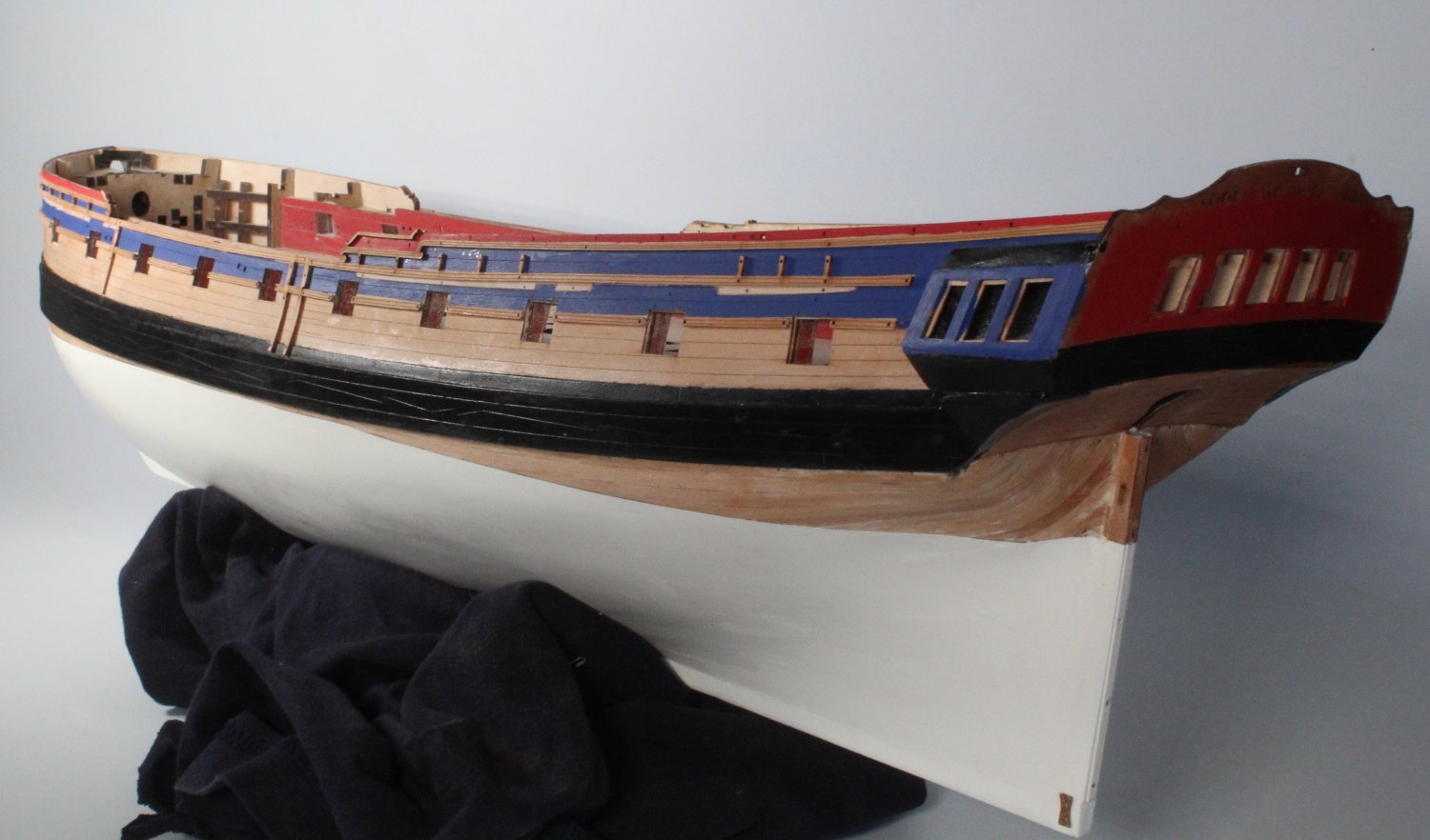
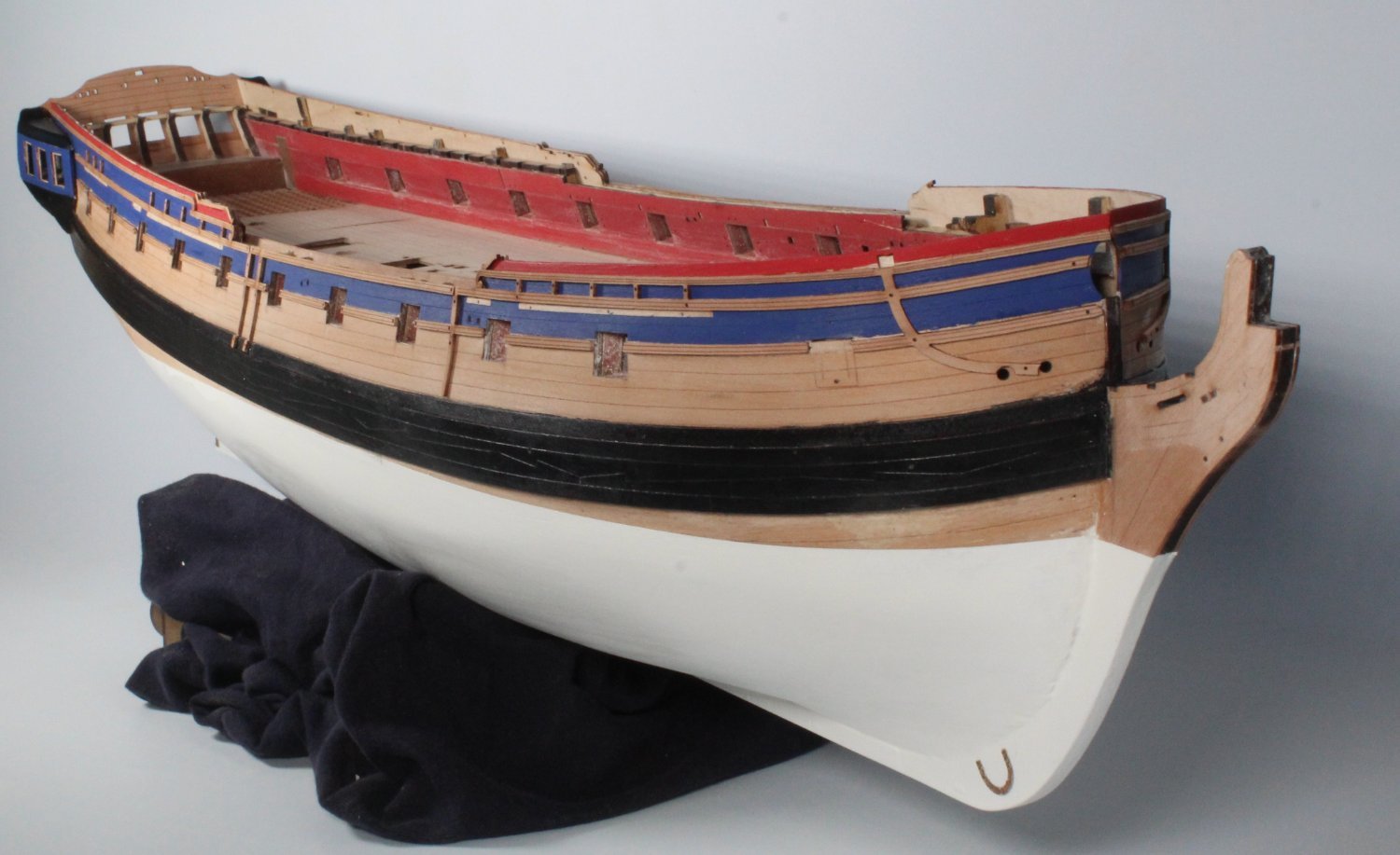
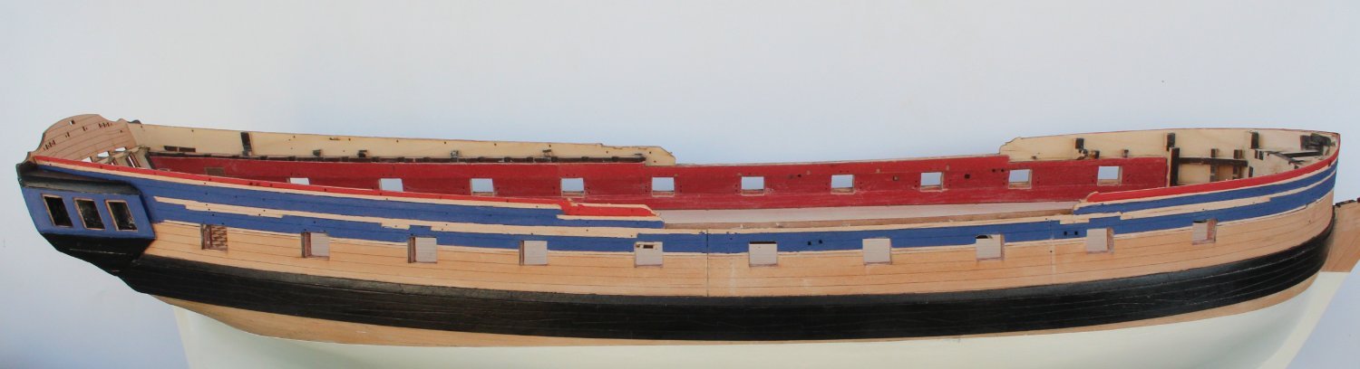
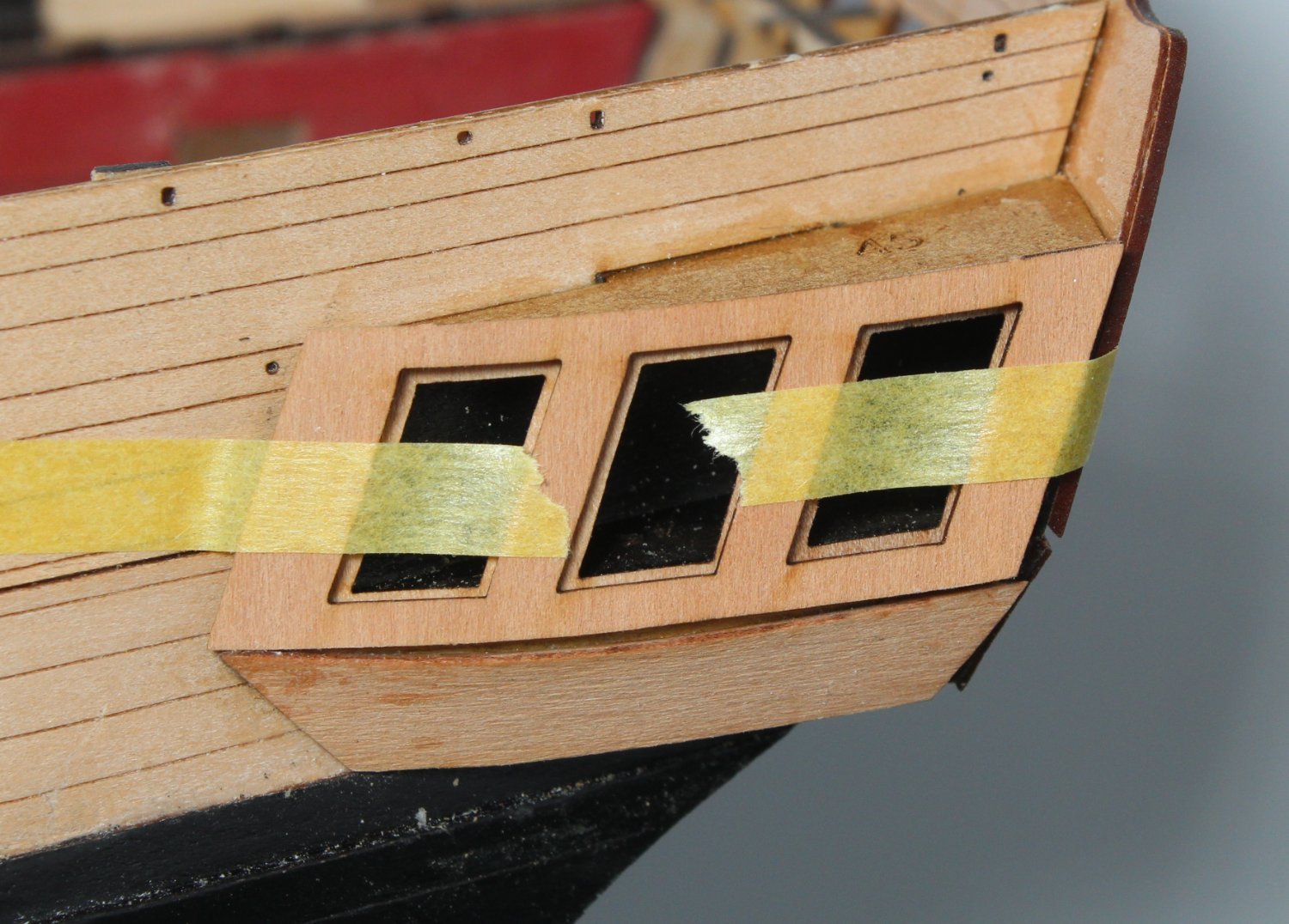
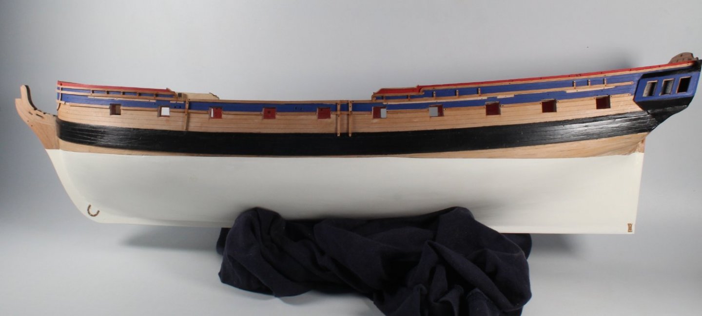
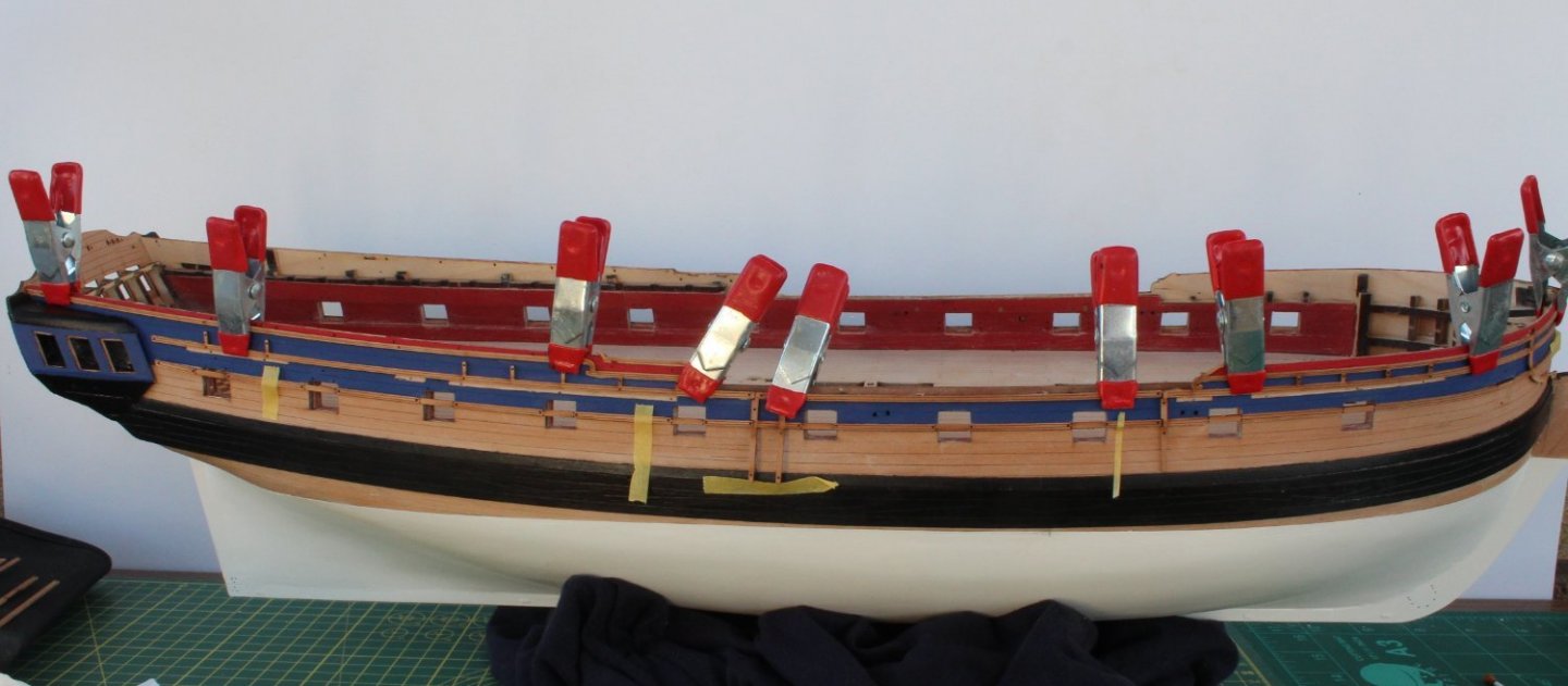
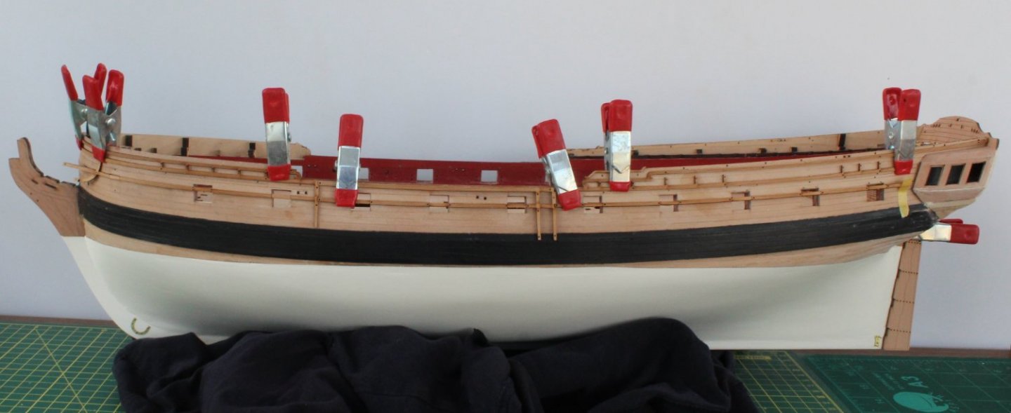
Painting Today I have been painting the hull. The hull had already been taped, as per my previous post when I applied the WOP. I applied 3 coast of the red, blue and black paint to the various parts of the hull, quarter galleries, upper stern counter and stern fascia pattern. The first photo shows the right-hand side of the hull. The next two photos shows the stern area of the each side The next two photos show the bow area. The next photo show the stern counter and fascia area. The next two photos are close ups of the quarter galleries I have dry fitted the various rails to make sure I was happy with the painted areas on the hull. The next 5 photos shows how the hull will look with the rails fitted, noting I will soak and bend the bow rails overnight. FInally I have fitted the pintle straps to the rudder, noting I still have to add the shortened brass pin to the holes.


- 476 replies
-
- 6
-
-
- sphinx
- vanguard models
- (and 1 more)
-
Many thanks Yves. I am pleased with my 2nd attempt at building the Sphinx.
-
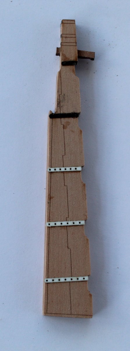
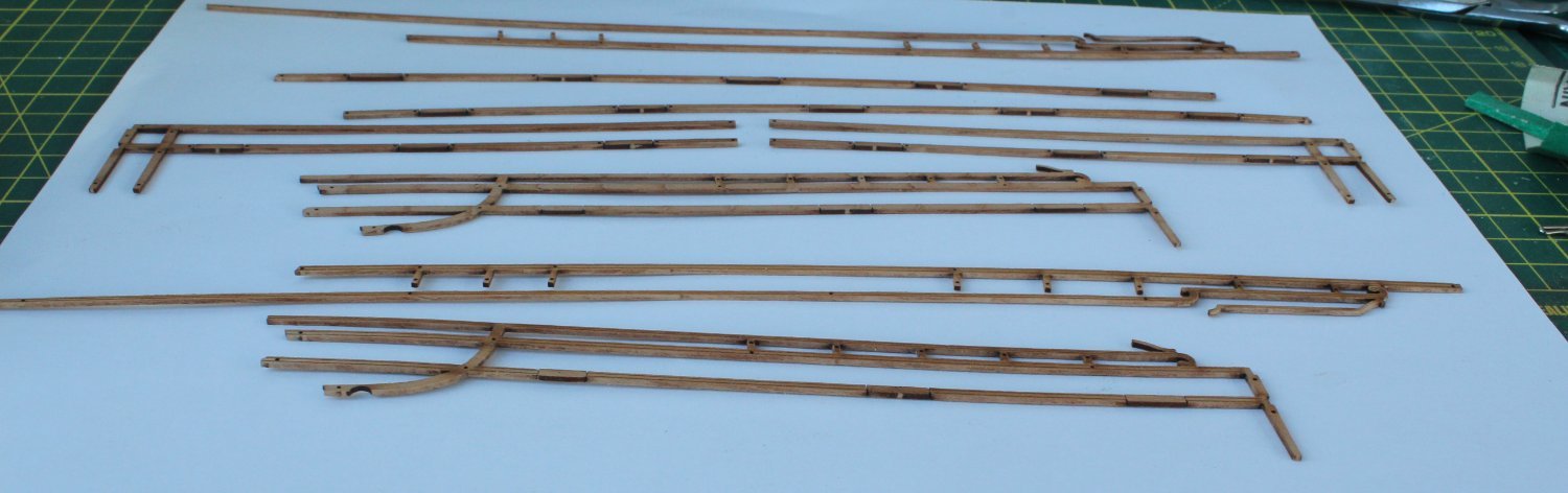
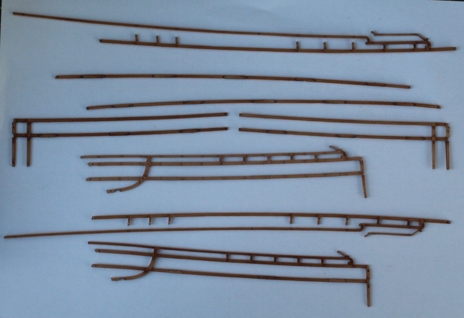
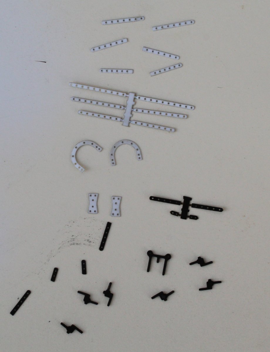
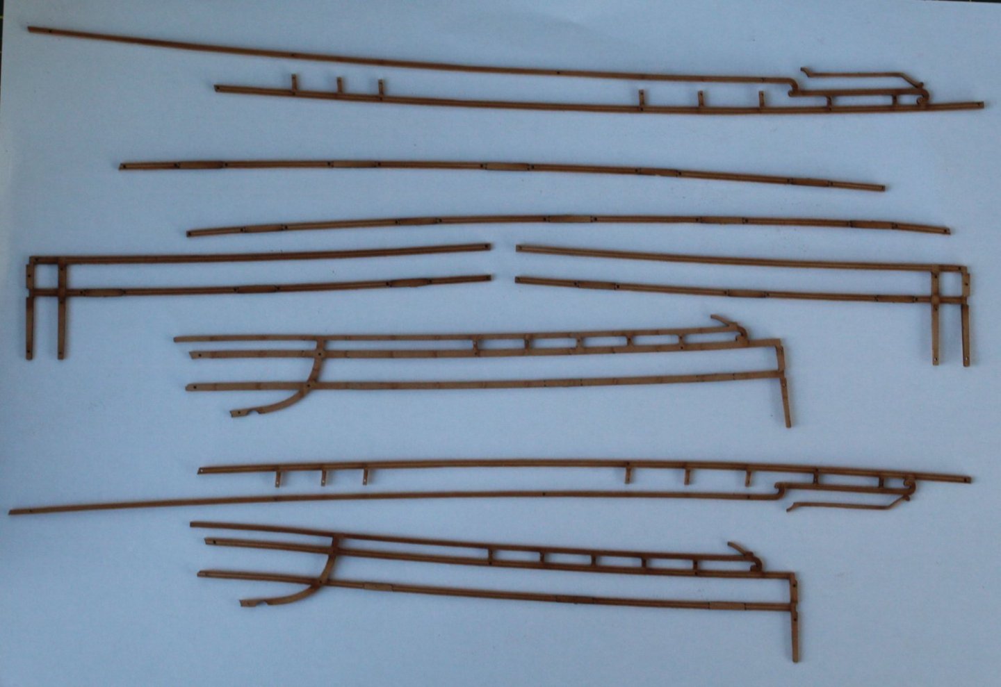
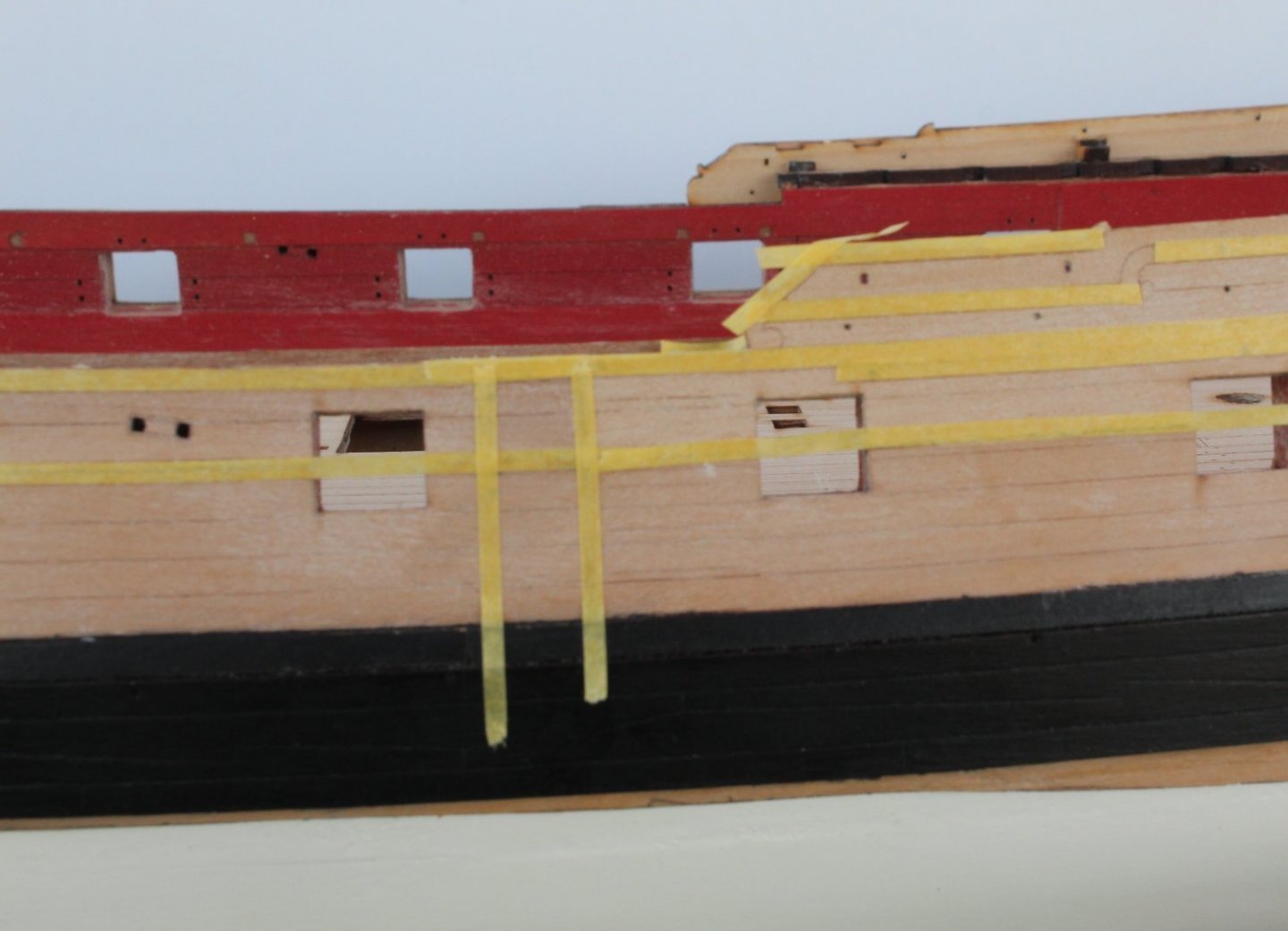
Preparation Work The last couple of days have been spent as preparation for the next phase of the build. The first task undertook was to remove the laser char from the various rail patterns. Rather than split the rails up I decided to see if I could remove the laser char with the rails in tact. Using a mixture of scraping with a sharp blade and sandpaper I actually managed to complete the task with all the rails still in one piece. I still plan to cut the rails which fit between the gun port openings before fitting. The laser char that is visible on the photo below are on the rail parts which sit over the gun ports which will be discarded. The next task was to prepare the rudder PE parts. These parts were all cleaned in warm soapy water before being placed in acetone. Some of them were then blackened and some sprayed with a coat ofr primer, in readiness for a coat (or two) of white paint. The horseshoe and fishplates have also been primed and are now ready for a coat )or two) of copper paint. The area where the rails will be fitted to the hull were covered with 2mmW masking tape before the WOP and paint could be applied. The area's on the hull where the channels will fitted were also taped. The hull was then coated with a wipe on poly (WOP) coat, using two paint brushes. The first paint brush applied the WOP mix (50% poly varnish and 50% white spirit) which was then brushed away using the second brush. Once the WOP has fully dried out the hull can be painted. State of play after the WOP


- 476 replies
-
- 11
-
-
- sphinx
- vanguard models
- (and 1 more)
-
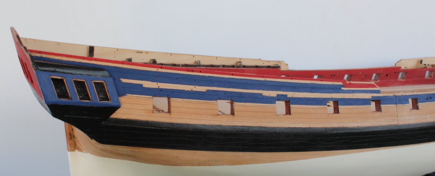
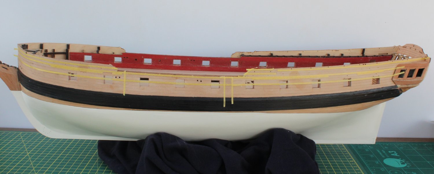
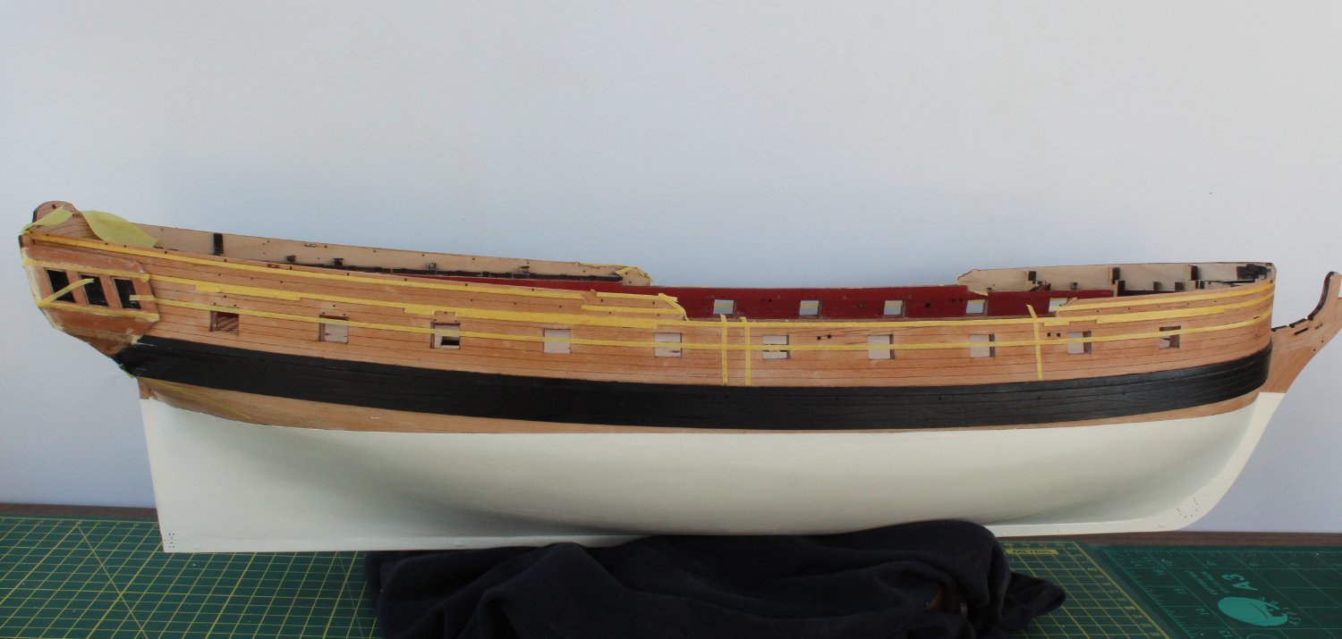
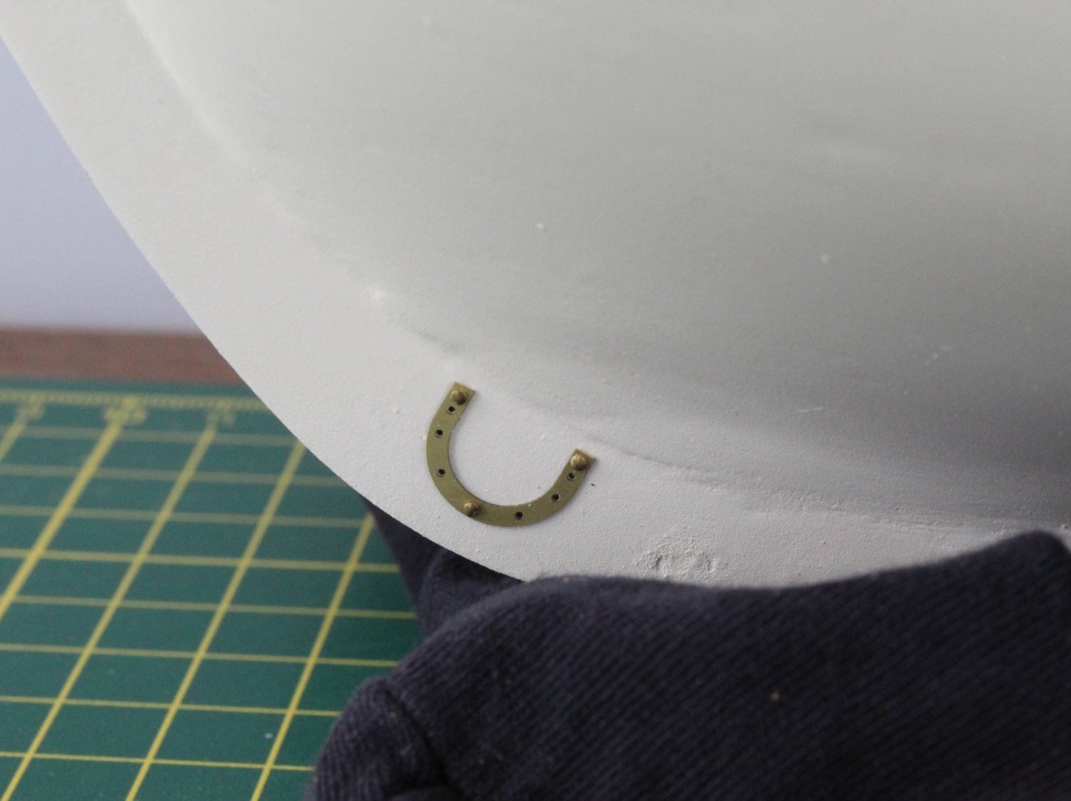
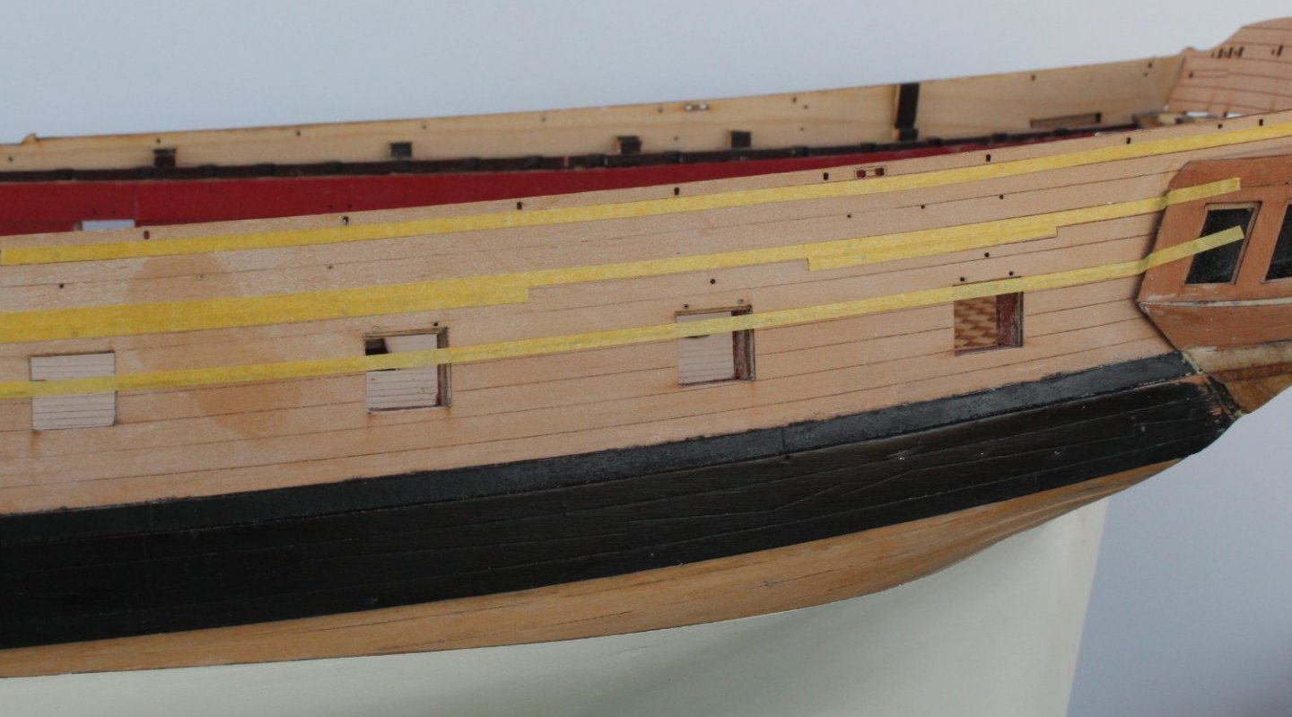
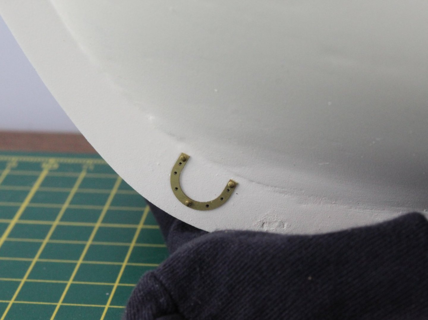
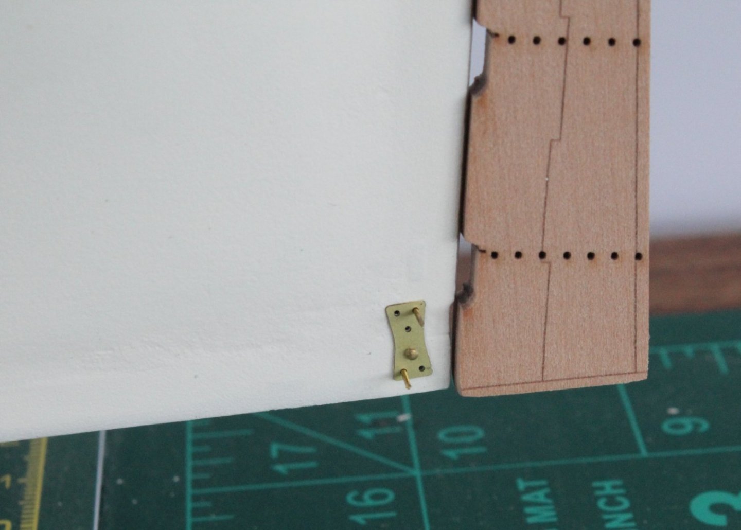
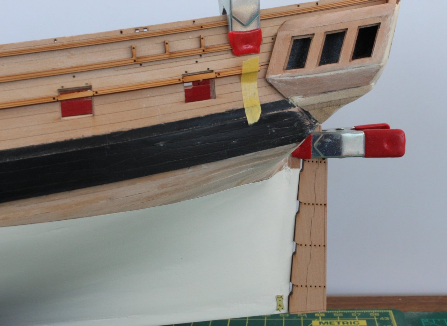
Hull Painting and Dry Fitting Next Stage The masking tape was removed this morning and I was very pleased that there was no bleed. The hull is looking good, not perfect but much better than my previous builds which required a white painted hull below the waterline. Planning ahead I have glued the two outer rudder patterns to rudder. I have also removed the laser char. I have also removed the various rails from the 1mm sheet and these have been dry fitted to the hull. I think I will follow previous builders examples with regards to removing the laser char from the rails by cutting the rails up into smaller pieces. The horseshoe and fishplate have also been dry fitted. The photo below shows the Sphinx with the rails, horseshoe and fishplate and rudder dry fitted. The next photo is a close up of the horseshoe dry fitted in position The next photo is a close up of the fishplate dry fitted in position The next photo shows the rudder in position and the stern rails dry fitted. The final two photos shows the midships and bow areas with the rails dry fitted.
- 476 replies
-
- 14
-
-
- sphinx
- vanguard models
- (and 1 more)
-
Thanks Mark. I will be taking the tape off with a mix of fear and excitement. Hopefully I have made a good job of masking.
- 476 replies
-
- 3
-
-
- sphinx
- vanguard models
- (and 1 more)
-
Thanks, so much happier with the v2 build as I made a right pigs ear with the tricky quarter galleries with my v1 build
- 476 replies
-
- 2
-
-
- sphinx
- vanguard models
- (and 1 more)
-
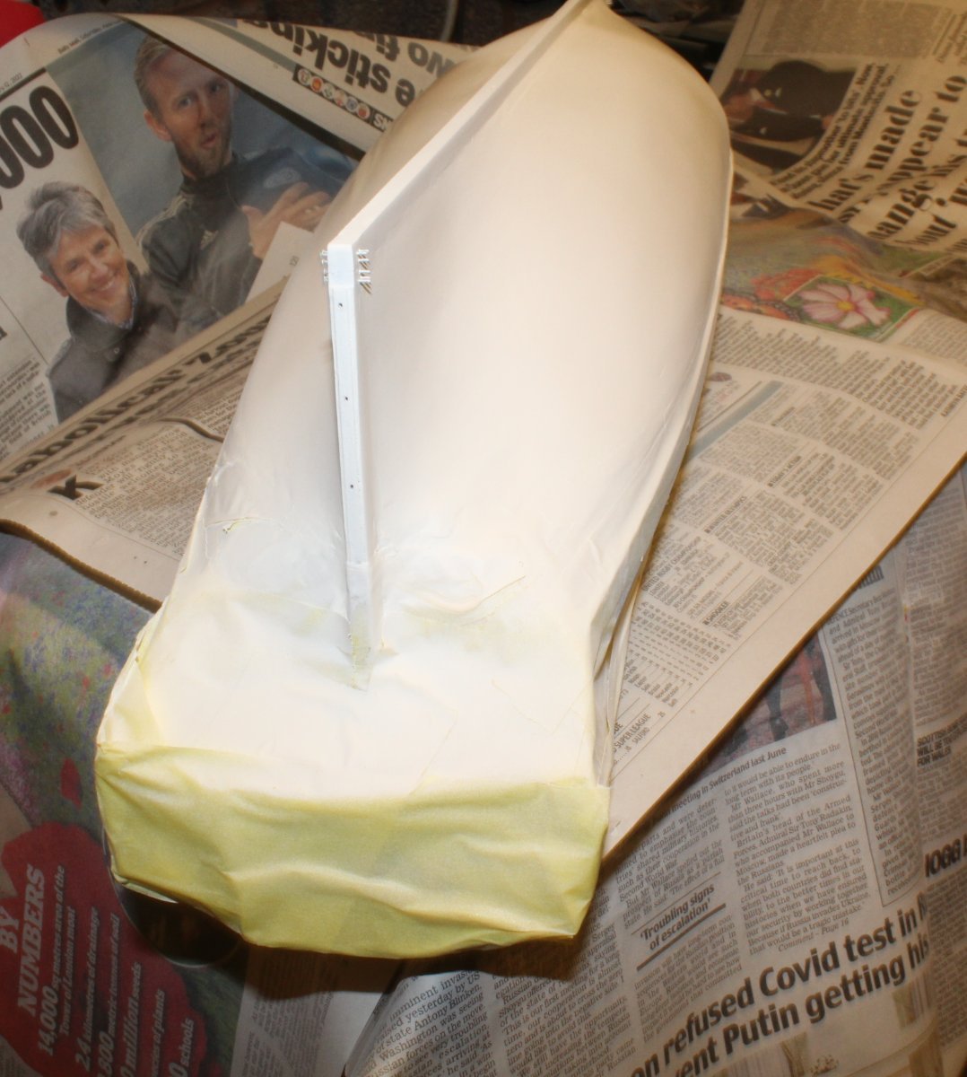
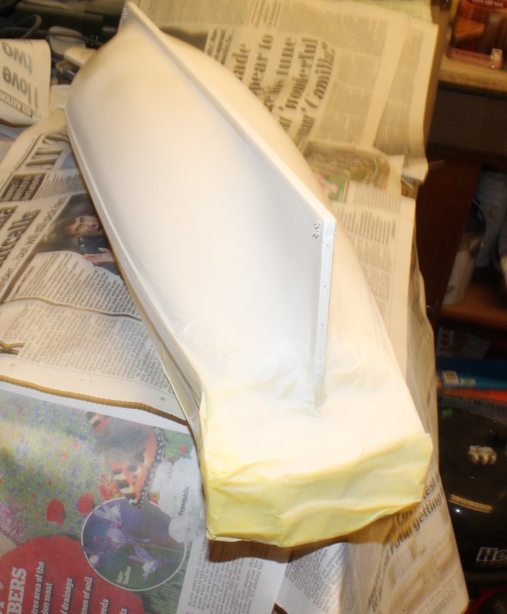
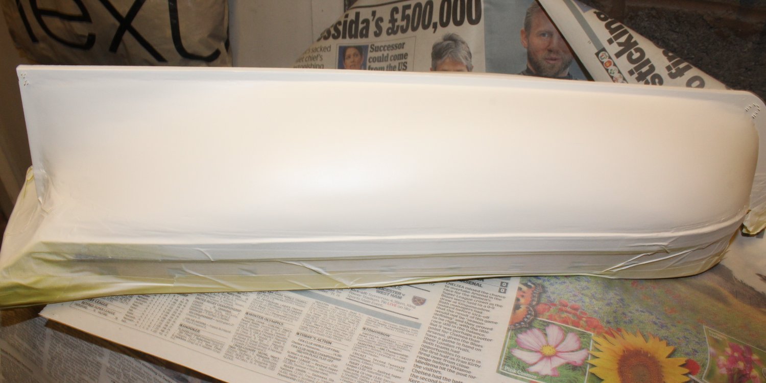
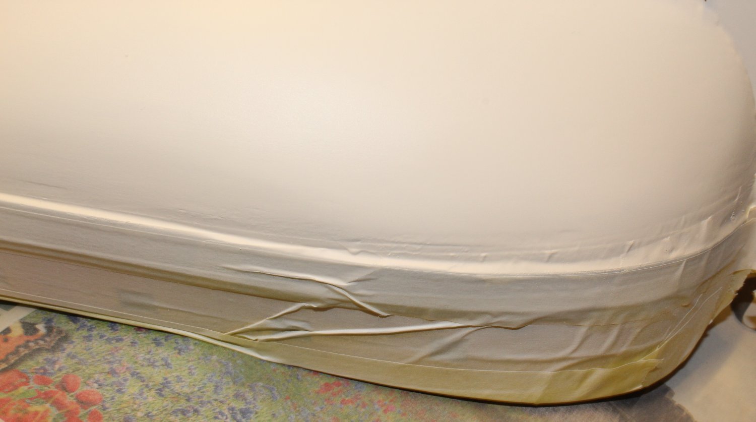
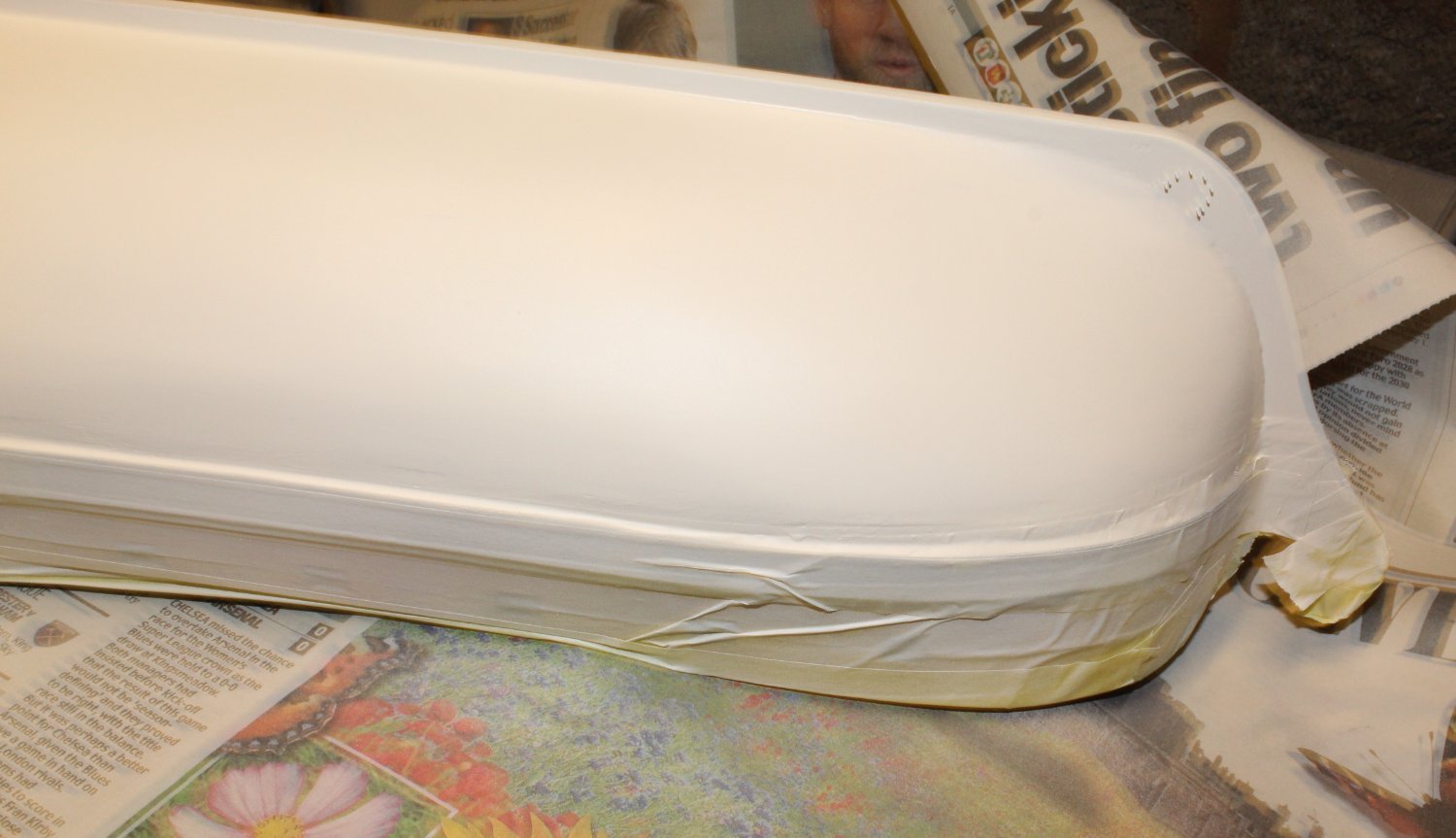
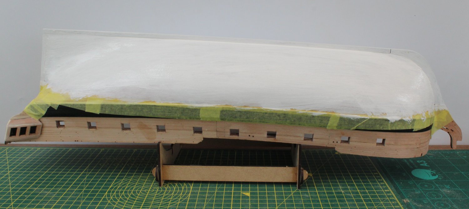
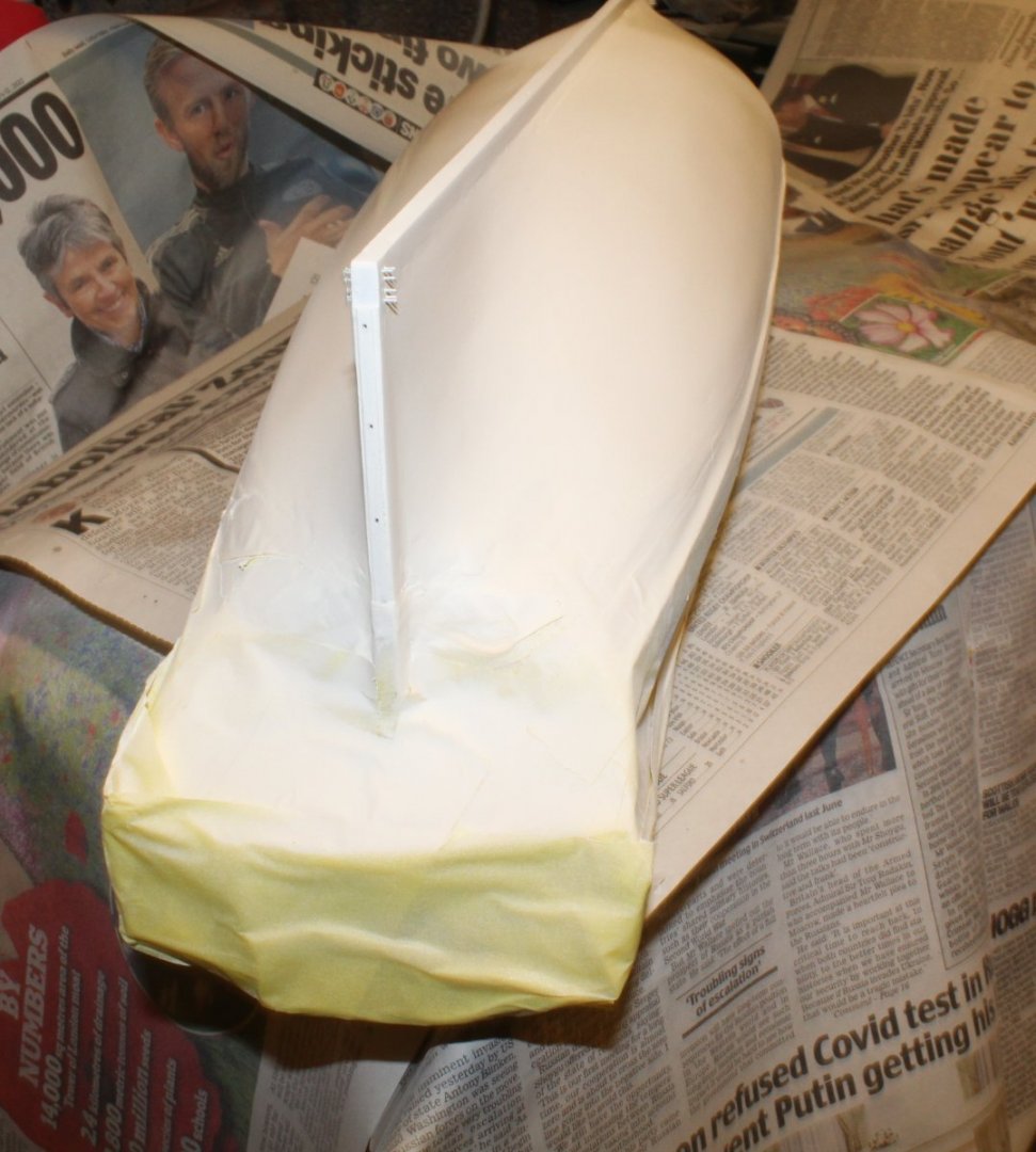
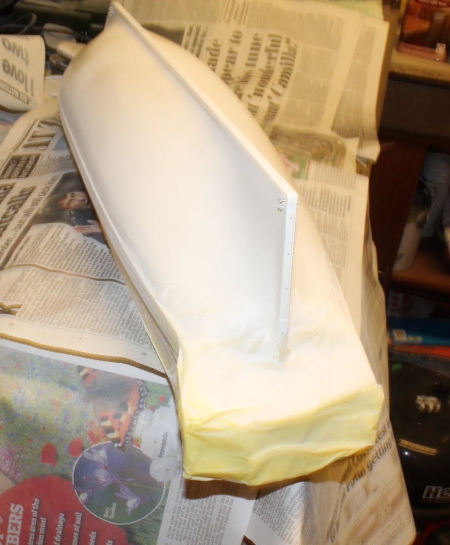
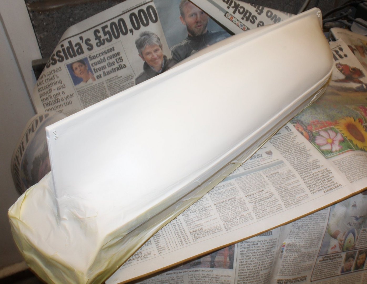
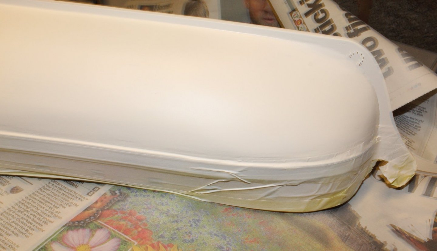
Painting The Hull White I have spent the last few days painting the hull white. This has been a long drawn out process. After each coat of paint a filler mixture was applied to fill the various depressions. I used wood filler mixed with titebond and water to fill the depressions. Once the filler mix had dried the hull was sanded, taking off the excess filler and most of the paint. The hull was then repainted white. After 4 (or 5 interations) of this process I reached the stage where I was resonably happy with the look of the hull. It felt and looked smooth so I sprayed two final coats of white paint. It is not 100% perfect but I think it passes muster. The hull is still in the paint shop and will be left overnight to allow time for the paint to fully dry. Fingers crossed the taping has done its job. Tomorrow will be the day of the big reveal. As can be seen in the photo below I inserted pins in the horseshow and fishplate holes to ensure the remained paint free.


- 476 replies
-
- 6
-
-
- sphinx
- vanguard models
- (and 1 more)
-
Looks very nice. You may need to trial fit the knees. I think they will be easier to fit before it gets to crowded.
- 857 replies
-
- 2
-
-
- Sphinx
- Vanguard Models
- (and 1 more)
-
Hello Mark I use a deadeye jig which has worked very well for both my Duchess of Kingston and Alert builds. I have added a couple of links to my build posts which shows the jig in action. Deadeye Jig (Alert) Deadeye Jig (DOK) Glenn
- 505 replies
-
- 4
-
-
- vanguard models
- Sphinx
- (and 1 more)
-
Looks very nice, great work
-
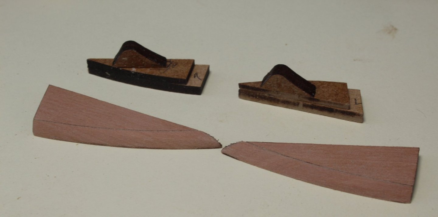
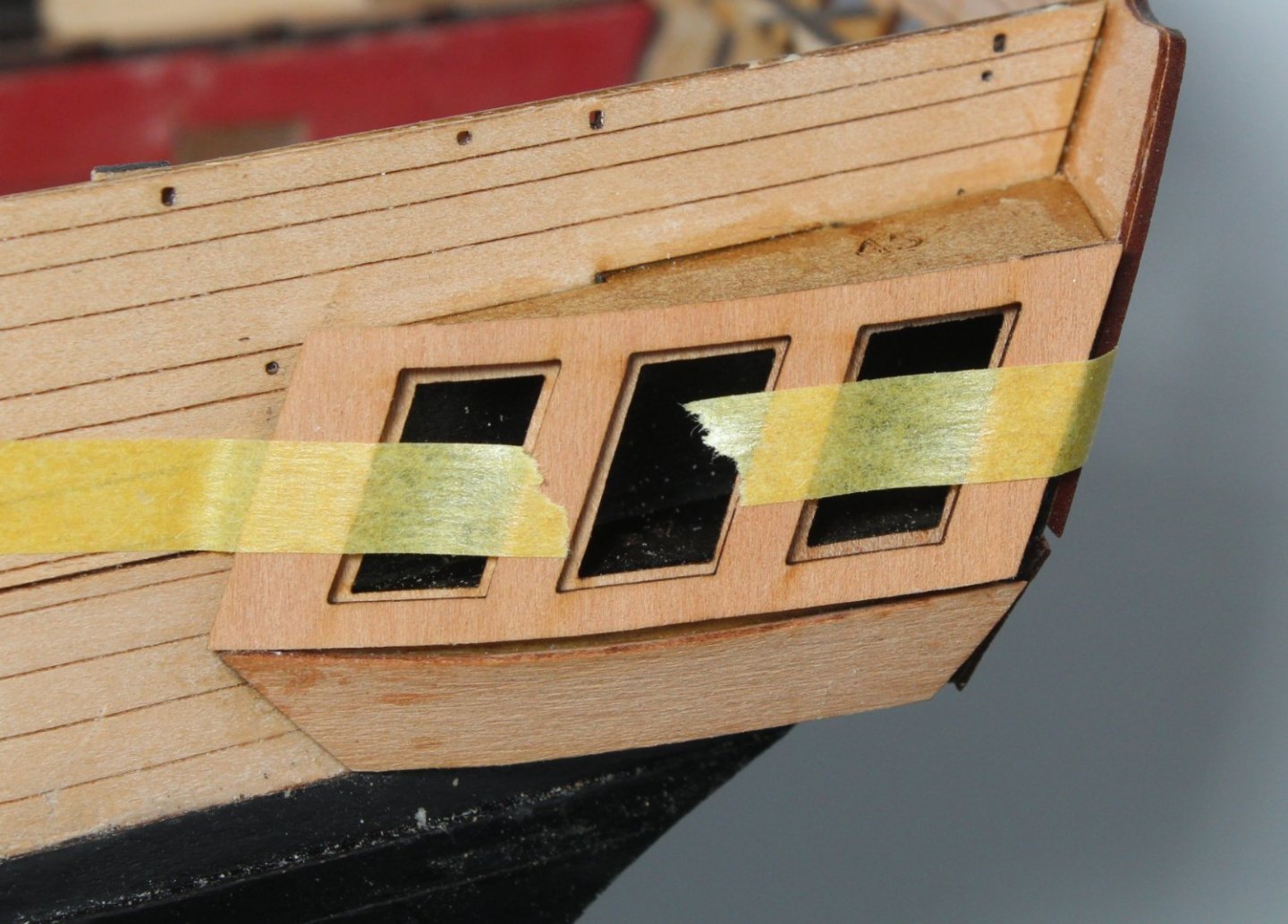
Quarter Galleries and Hull Painting The first task today was to complete the lower finishing pattern for the quarter galleries. Using a rotary tool I carefully shaped the stern end. Once I was happy with the shaping of the stern end I moved on to bevelling the front end so the top edge was flush with the berthing pattern and the lower edge was tapered to a fine edge. Once again I used my rotary tool I took my time with plenty of test fits during the shaping process to make sure it was a good fit. I also used a sanding block and sanding paper for the final shaping. The photo below shows the right-hand side. I have added the filler to the side of the window pattern/ berthing pattern. I did managed to break off the leading edge of the lower finishing pattern during the shaping process. I have started to add some filler to correct and it will look Ok with a bit more fettling and then painted black. The photo below is the left-hand side quarter gallery. Again this will look Ok when the black paint has been added. The photo below show the stern view. It does not look too bad, but I will need to add a bit of filler before the black paint is added Next I taped the hull above the waterline, and using Admiralty Matt White diluted with water I brushed on the first coat of paint. Once the paint has had time to dry I will inspect the hull and then sand and fill as necessary. I am hoping this will not require too much as I did quick a bit of work in this respect when I completed the second planking. I plan to use diluted Admiralty Matt white and once I am happy the hull is smooth. If necessary I will finish off with a spray can final coat. The photo below was taken after the first coat of diluted Admiralty Matt white paint had been brushed on the hull


- 476 replies
-
- 10
-
-
- sphinx
- vanguard models
- (and 1 more)
-
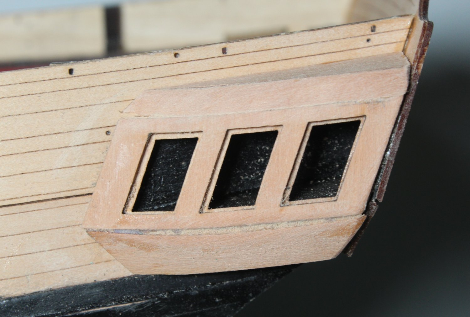
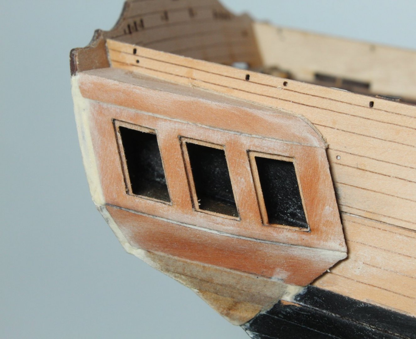
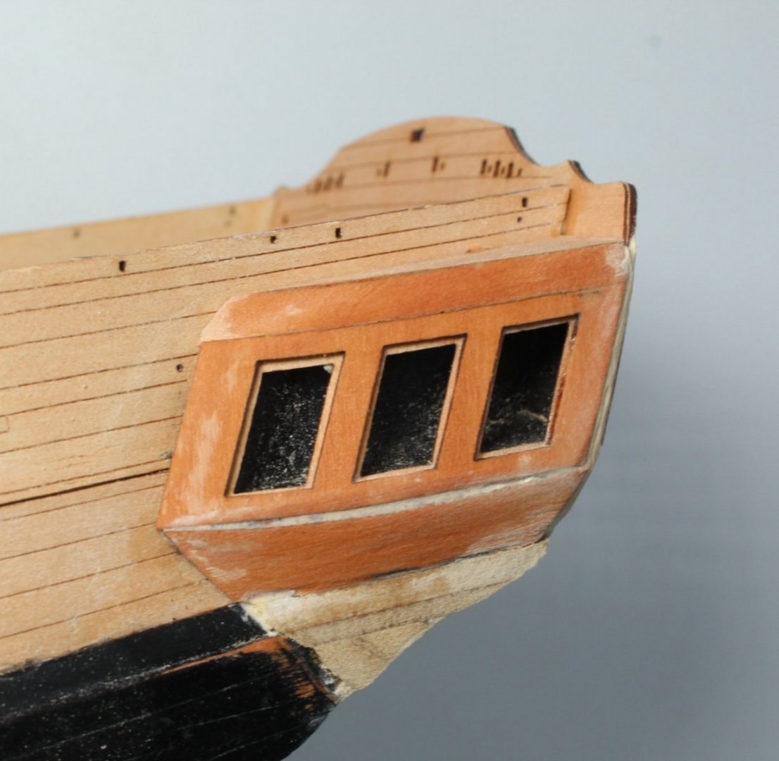
Work on Quarter Galleries Continues As with stern fascia pattern I decided to trial fit the windows to the quarter gallery window frame. They all required a bit of fettling to make them fit. Next I bevelled the front edge of the upper patterns. I also assembled the lower finishing patterns. Next I did a dry fit of the window pattern to make sure. As everything looked good. I spent a bit more time shaping the upper patterns. Once I was happy it was time to glue the various parts in place. The right-hand side looks reasonable Ok. As can be seen in the photo below I will need to fill the edge between the stern fascia and window pattern This is the left-hand side which will also require a little bit of filler. I also need to blow and brush the dust away.


- 476 replies
-
- 8
-
-
- sphinx
- vanguard models
- (and 1 more)
-
Many thanks Malcolm, overall I am very happy with this build.
- 476 replies
-
- 1
-
-
- sphinx
- vanguard models
- (and 1 more)