robdurant
-
Posts
843 -
Joined
-
Last visited
Content Type
Profiles
Forums
Gallery
Events
Everything posted by robdurant
-
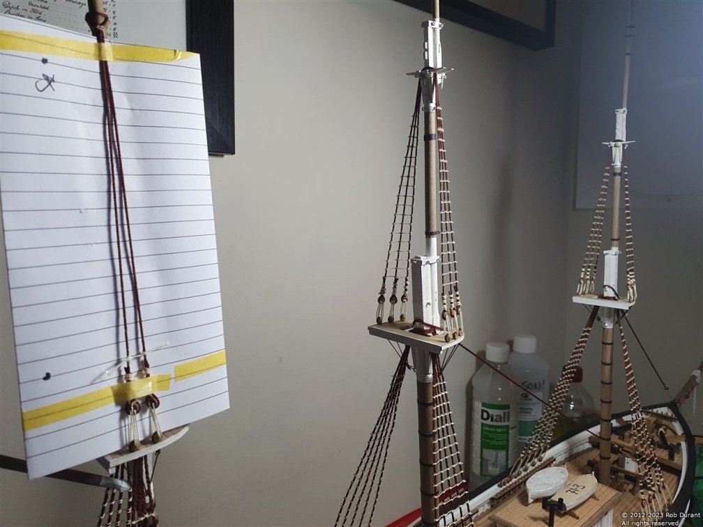
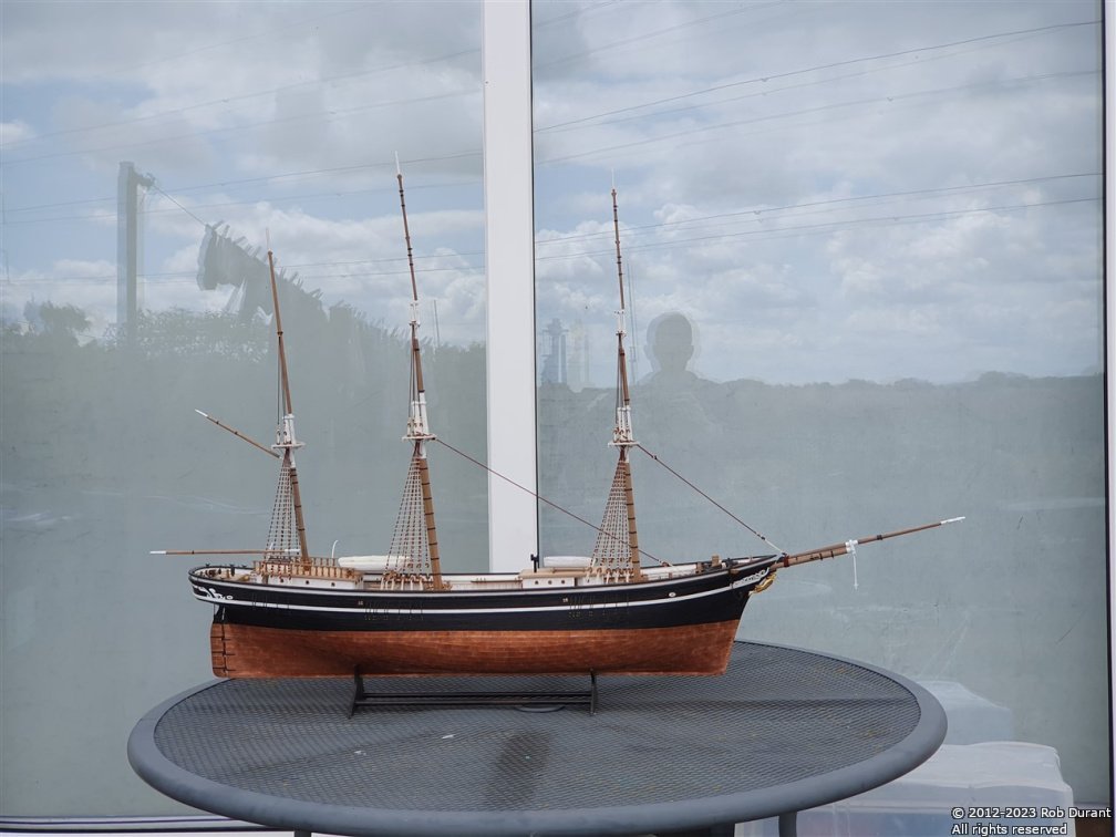
 It's been a while since I posted an update, but today I managed to get the remaining forestays, and some of the main stays set up. Here are a couple of photos of progress, since the weather was playing ball... Happy building, all Rob
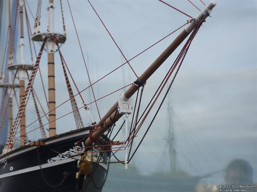
-
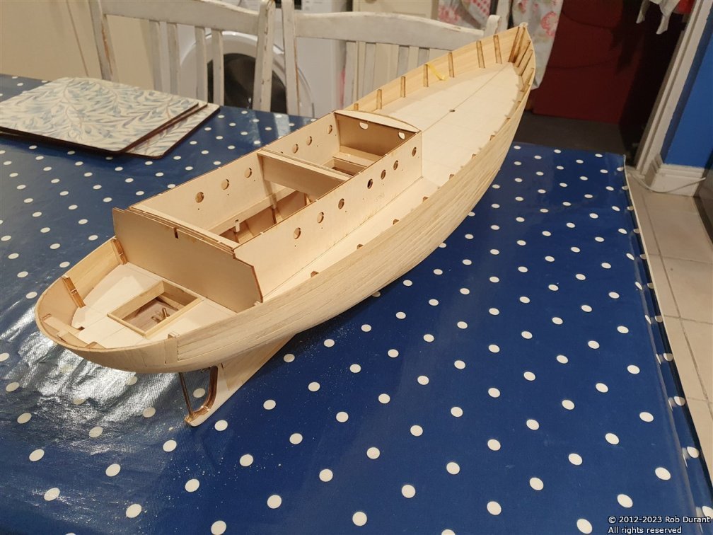
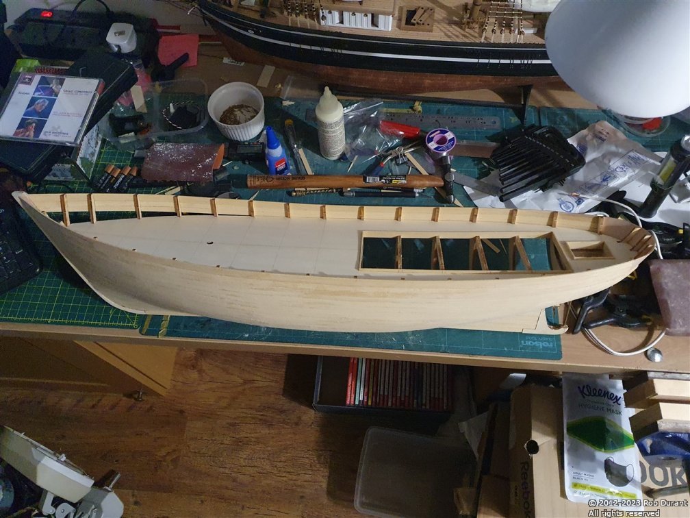
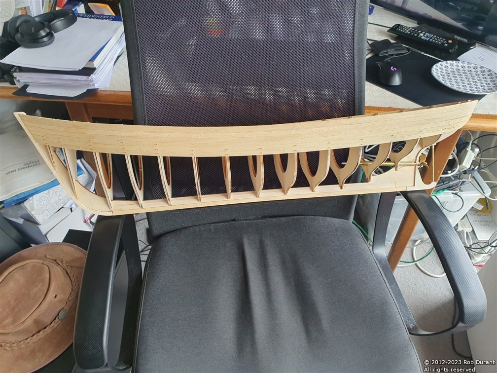
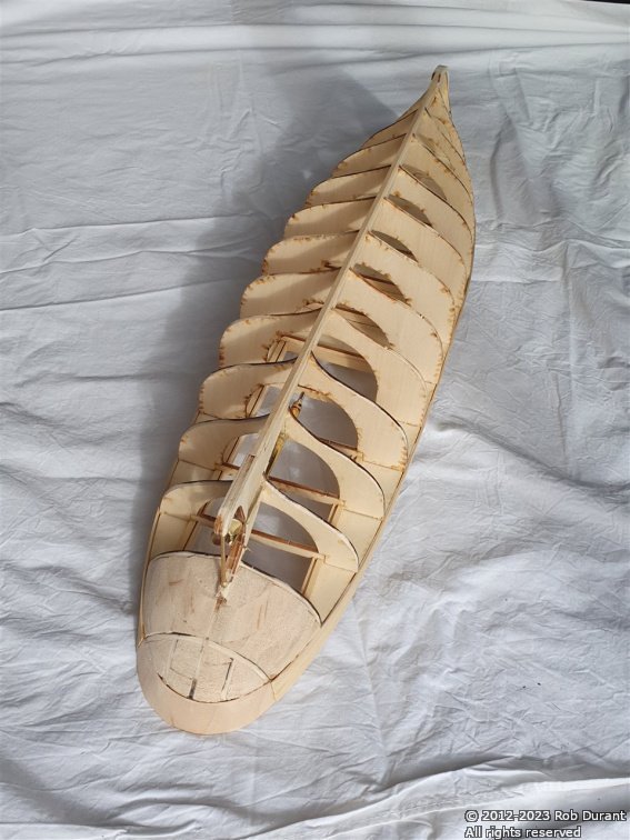
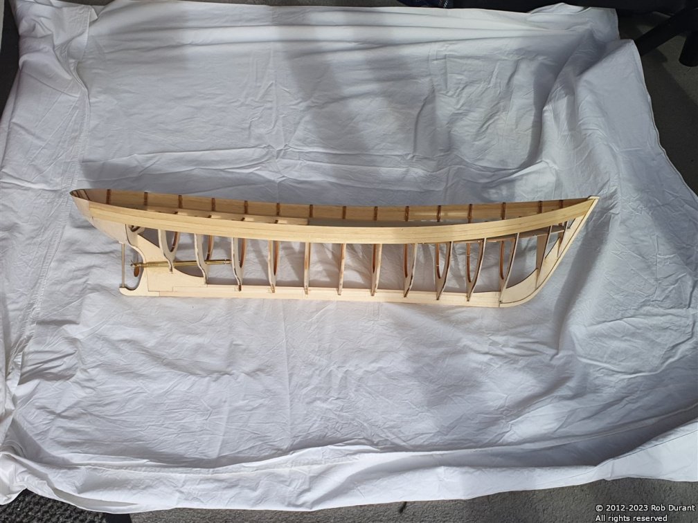
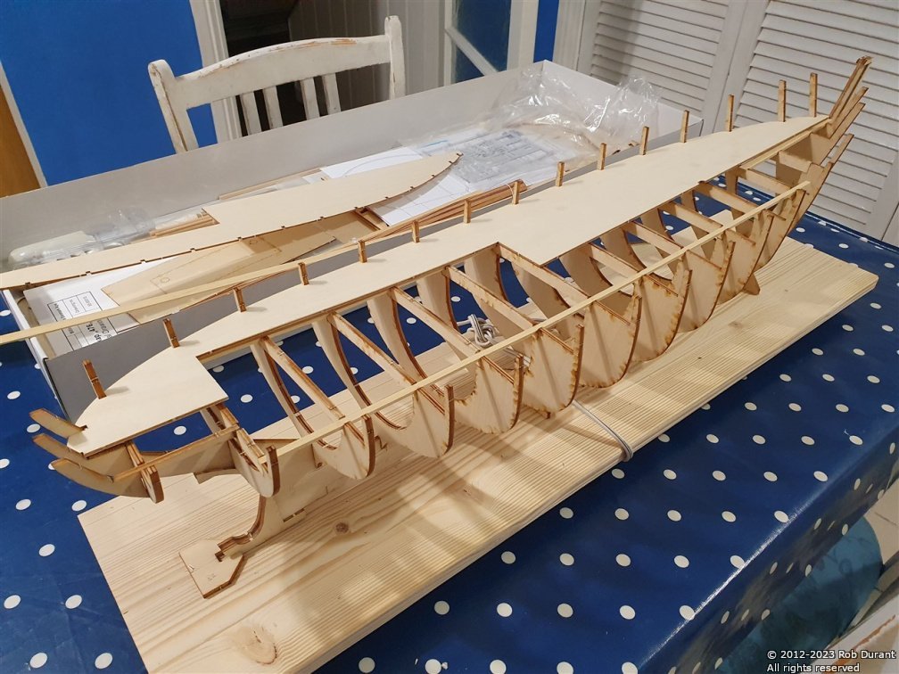
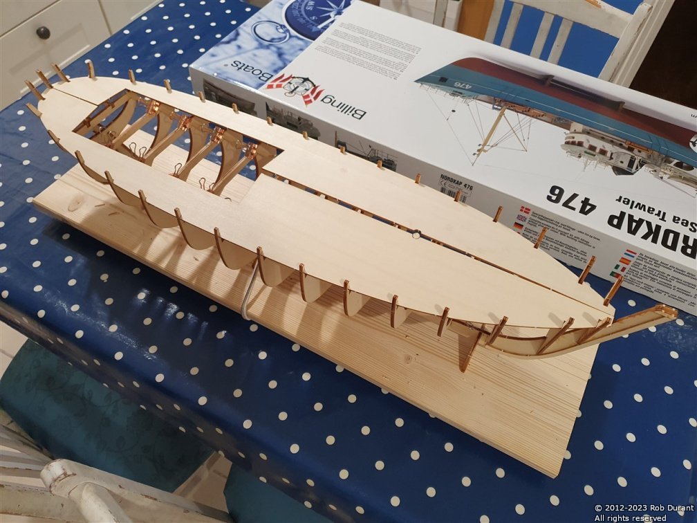
I've reached a milestone - the hull is closed up. I've also cut out the beams where the deck opening is to give space to access the motor, rudder servo, battery, etc... Thanks for looking in, for the likes, and the encouragement Rob
- 57 replies
-
- 10
-

-

-
- Nordkap
- Billing Boats
- (and 1 more)
-
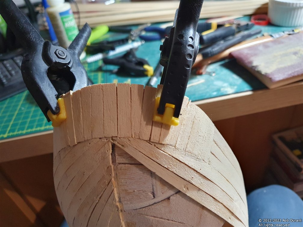
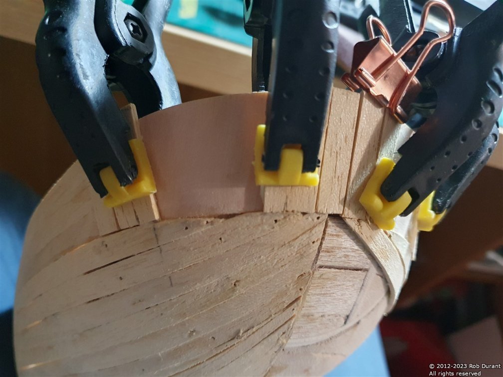
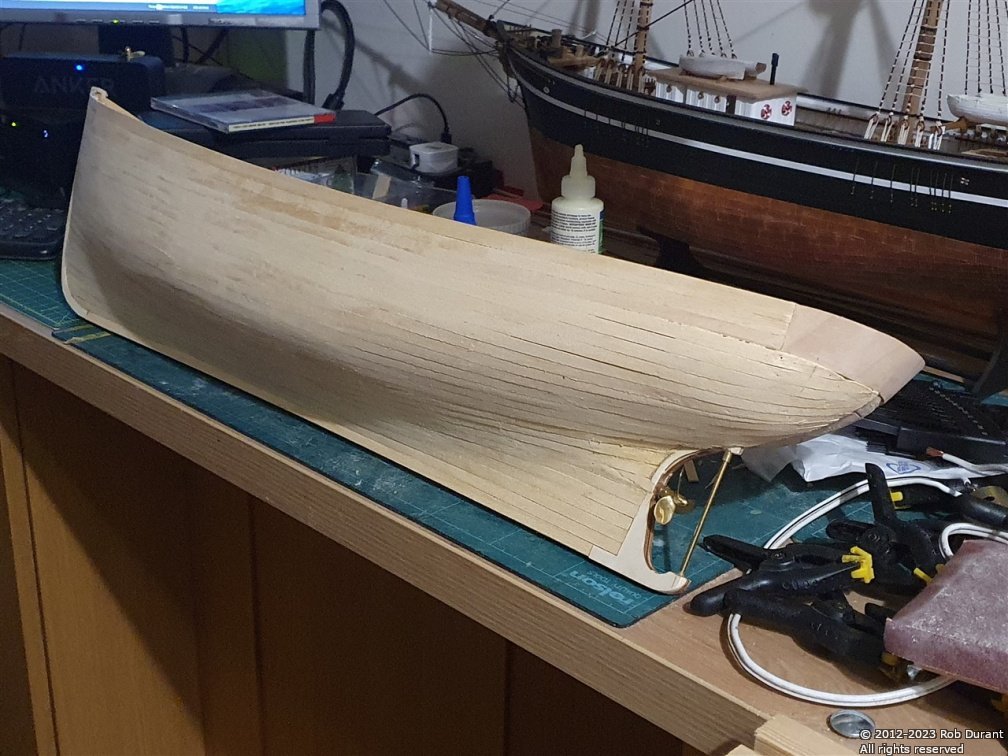
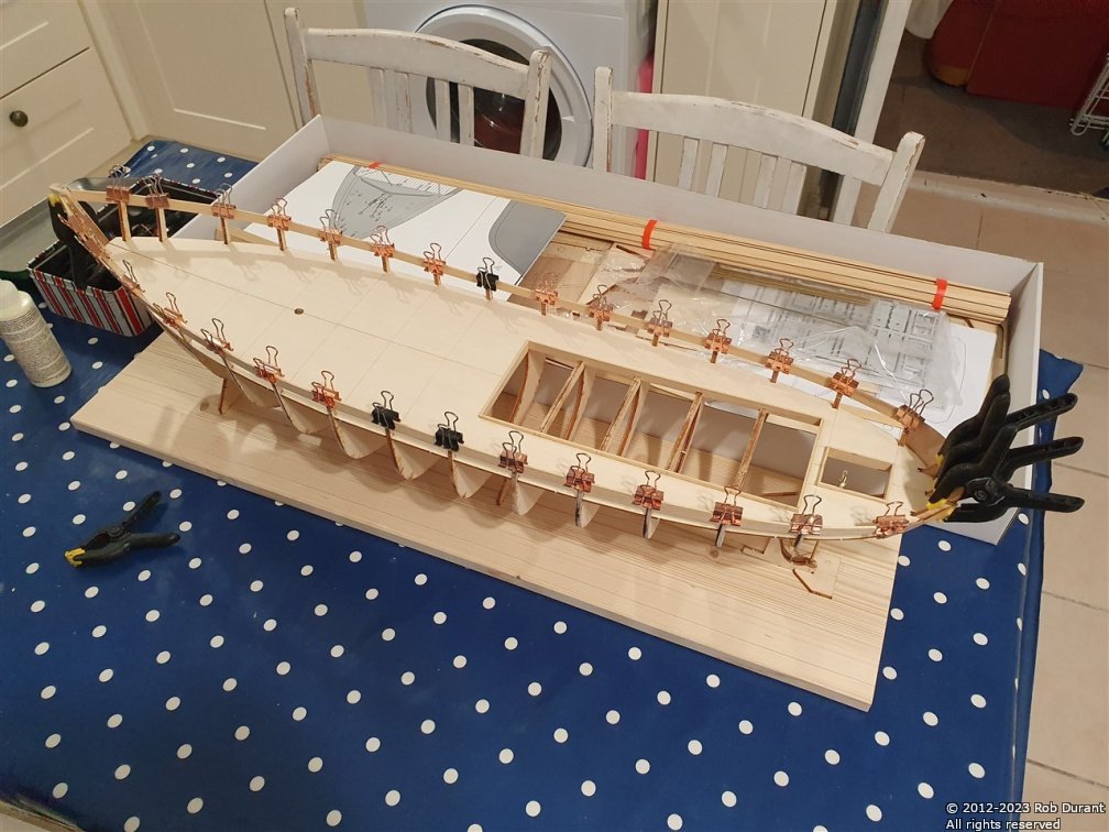
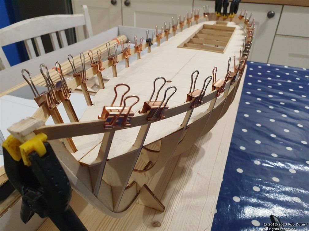
Thank you for these suggestions, Ian. I've moved the linkage in from the end of the servo arm to be approximately the same distance from the pivot as the on the rudder horn. I agree that this is a more sensible setup. As far as the rudder horn holes, I'm not sure why they'd be designed like that, but that's how the Billing Boats part came (unless I've just misidentified the part, and I'm using something that's meant for another bit of the build, which is entirely possible! 😂) I'm not too concerned about a small amount of slack in the system, as this is a scale fishing boat and not a high performance motor launch, so I'm not anticipating I'll need to be doing any precision manoeuvres at speed. It feels remarkably secure, and there's not a lot of slack in the system, so I'm happy enough. It helps keep the budget under control, and it's how I've always done it in my other RC boats There's not a huge amount of "interesting" progress to show, as I'm essentially just planking the other side of the hull to close her up... but I have planked vertically around the stern to bring the planking out to the same level. I've used offcuts of the planking strips to do this. And, planking on the starboard side, so far... I can normally get between three and five planks on in a session... The first nine planks from the bottom of the hull are full width... It won't be beautiful when it's finished, but it will be a solid base to fill and smooth. Planks are glued to the bulkheads, and edge glued to make it as solid as possible. The clamps towards the centre of the hull are to help the planks to glue nicely edge to edge, and to avoid clinker, as the bulkheads have quite a distance between them.
- 57 replies
-
- 5
-
-
- Nordkap
- Billing Boats
- (and 1 more)
-
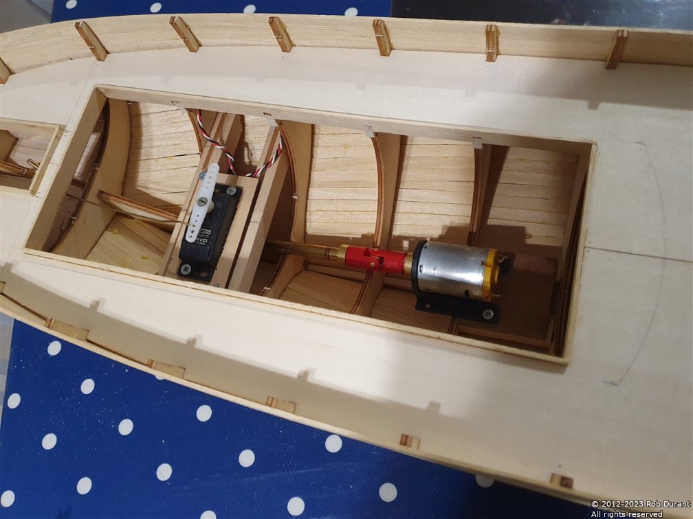
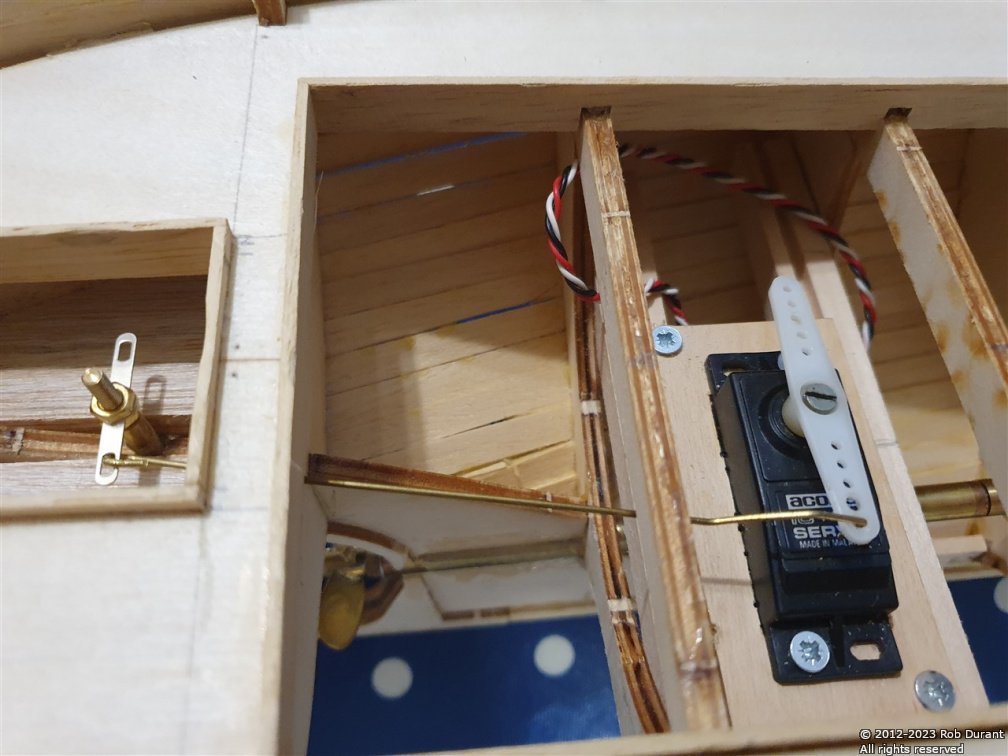
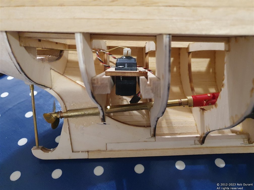
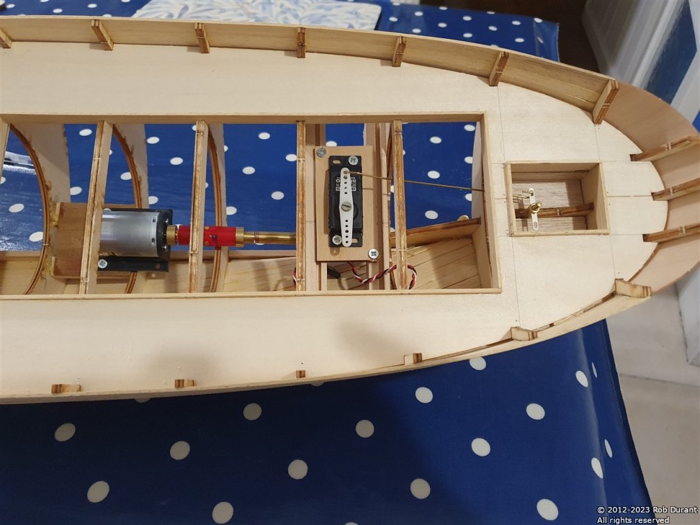
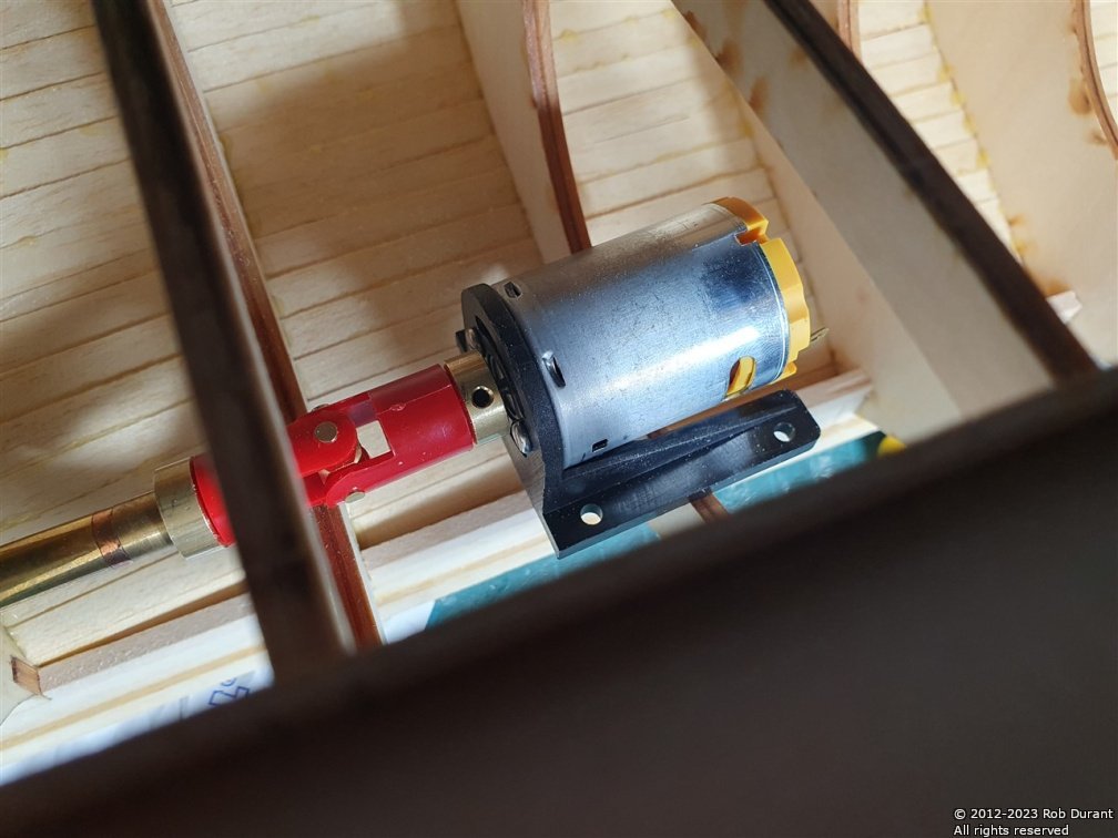
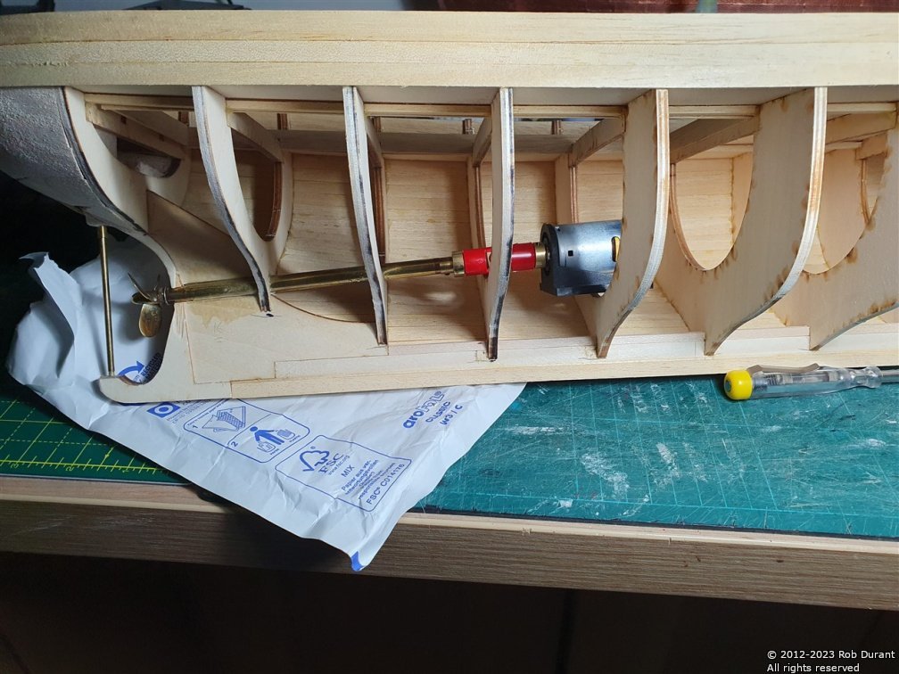
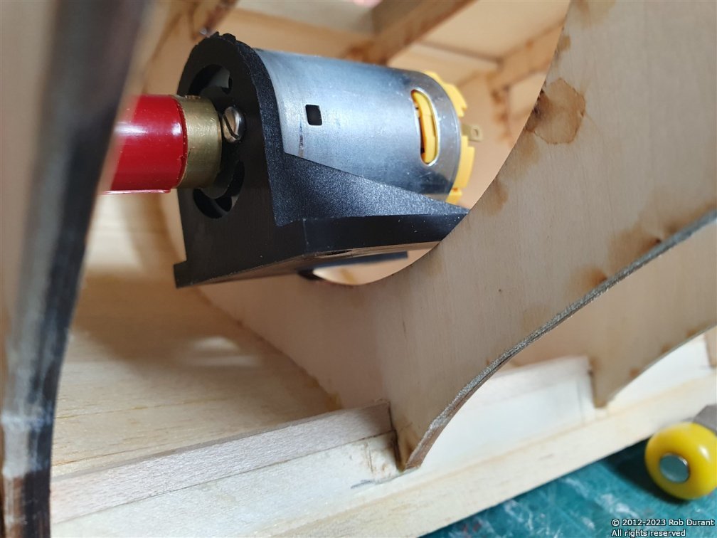
Thank you for the words of encouragement, @Ian_Grant. Yes, the prop-shaft and prop are from George Sitek - I've always been really impressed with their product, and that's no less true on this occasion. The rudder servo tray is constructed, with the servo mounted and fitted... I've also installed the motor on its own tray and mounted that between two bulkheads. Everything's screwed in place so that it can be removed as necessary through the access hatch above. The receiver will go next to the rudder servo. A bit of brass wire has been used as the linkage between the rudder post and the rudder servo. This is bent so that it doesn't hit the bulkheads as it passes forward. Altogether, I'm quite please. Here are some pictures of progress so far. I'm really glad I decided to do all of this before planking the other side closed... it's made life WAY easier

- 57 replies
-
- 7
-
-
- Nordkap
- Billing Boats
- (and 1 more)
-
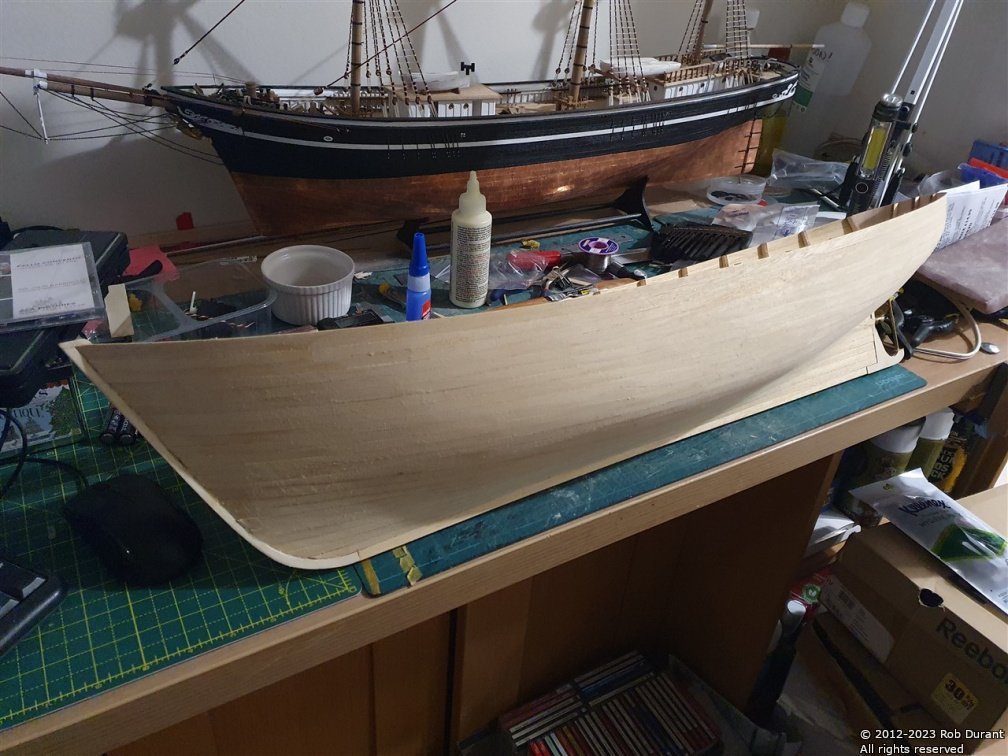
Thanks for the likes Planking continues... Port side is now planked, and starboard side well underway... I'll leave the serious sanding until I've got the whole hull planked. Also, the right parts for the universal coupling, along with a new motor arrived...
- 57 replies
-
- 8
-
-
-
- Nordkap
- Billing Boats
- (and 1 more)
-
A few more planks on the starboard side, and the sides added to the centre part of the keel.
- 57 replies
-
- 4
-
-
- Nordkap
- Billing Boats
- (and 1 more)
-
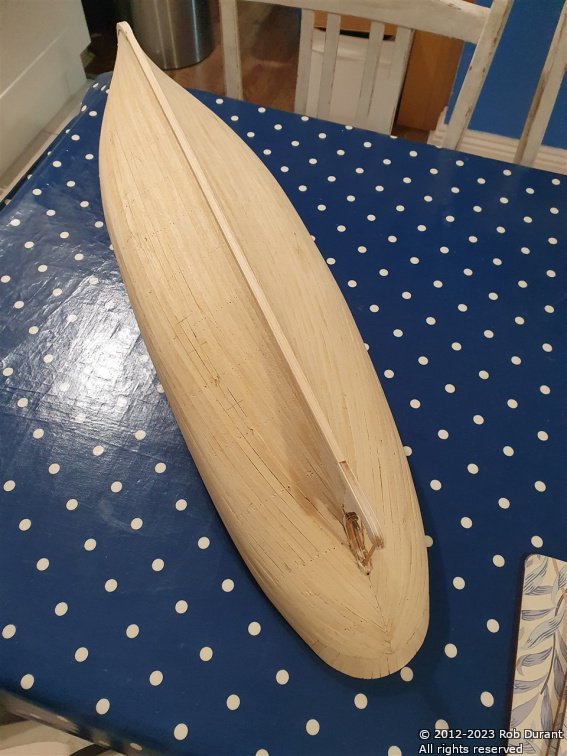
A quick update... I've added the first three rows of planking on starboard and port, and also filled in the stern between the bulkheads with balsa. To get a nice curved shape, this seemed like a necessity, especially as this model has only a single planking layer.
- 57 replies
-
- 6
-
-
- Nordkap
- Billing Boats
- (and 1 more)
-
Thank you for all the likes. The new prop arrived (38mm instead of 32mm, but with the same 4M (4mm) thread for the propshaft), and I'm much happier with how it fits the prop cutout at the stern. These George Sitek props are beautiful, and really lift the whole model. The Sitek props on my model of Cottesmore have taken on a beautiful patina with that deep bronze colour instead of the bright brass, and I'm sure this one will do the same over time. I've begun the planking process... this starts with the transom piece, which I pre-bent using the rib-bending iron. Then the uppermost planks were added (the top row is a 10mm strip, then the following strips are 7mm), lining up with the tops of the bulkheads. I love this stage where the hull lines begin to appear.
- 57 replies
-
- 5
-
-
- Nordkap
- Billing Boats
- (and 1 more)
-
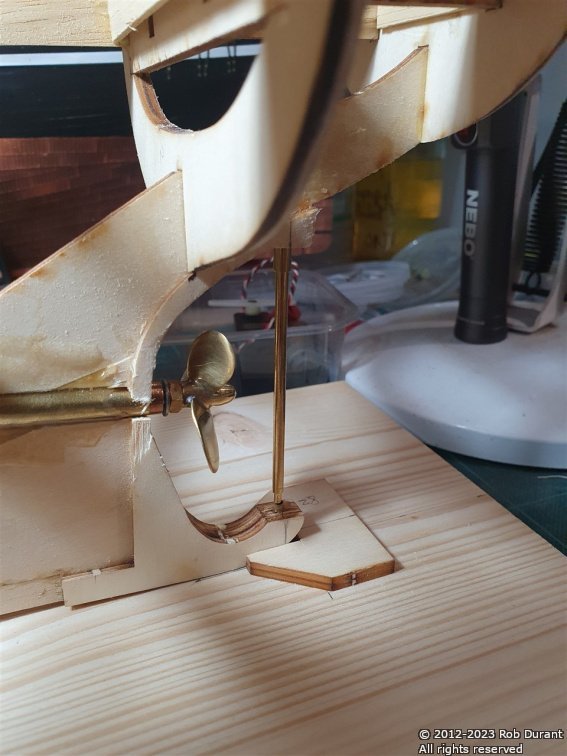
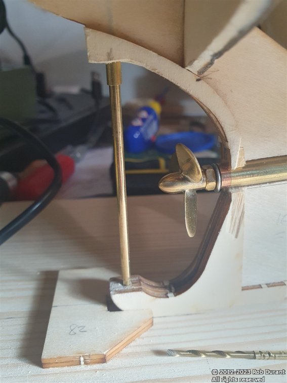
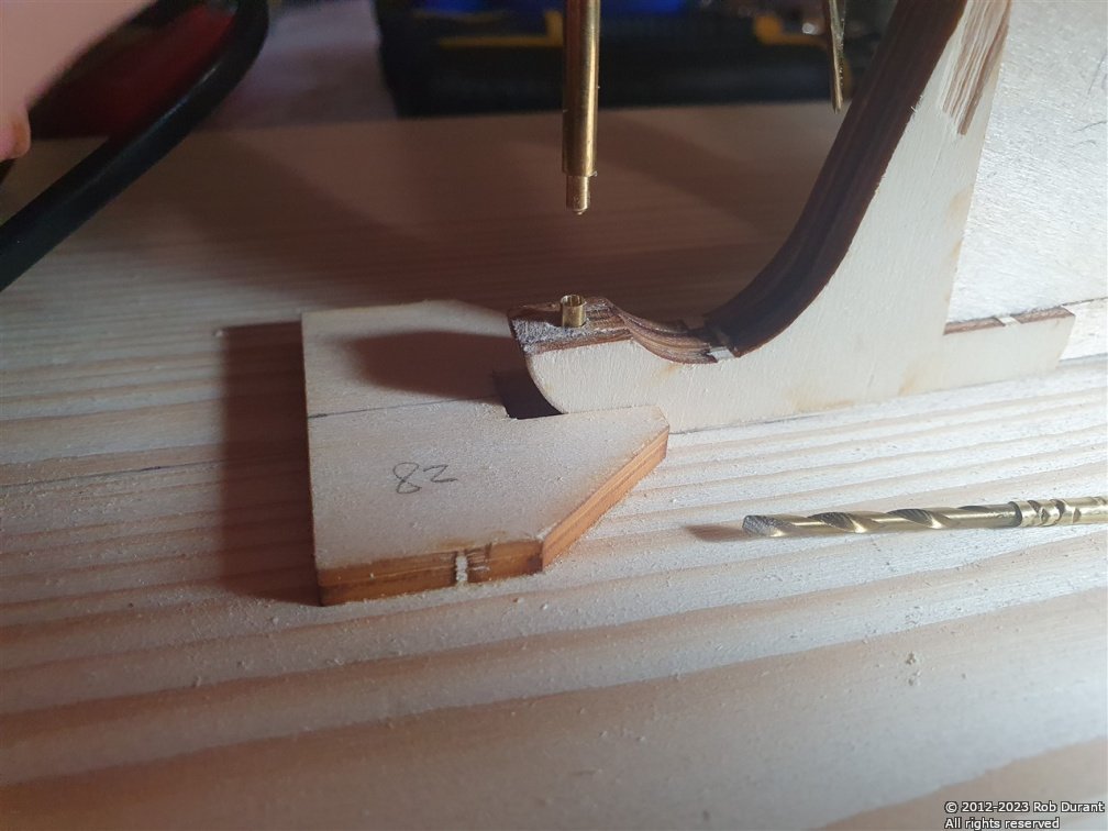
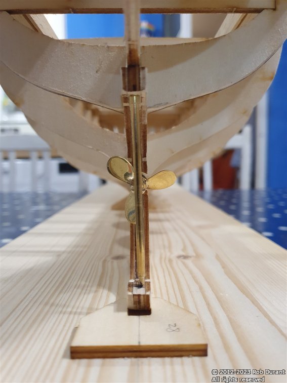
Well, one very enjoyable holiday later, I'm back, and this evening I decided to sort out the rudder post, where it sits in keel as it extends aft. The instructions don't say anything about the base of the post, and I was concerned that if it simply sat in a wooden hole it would a) wear loose over time, b) provide a way for water to get to the plywood over time. To avoid this, I ordered some 3.2mm brass tube, and I've used a 3-4mm length of it to create a socket for the rudder post to sit in. The hole for it was drilled using a drillbit on the end of a brass tube that was put through the rudder post to ensure it was lined up well. Once the hole was drilled, the brass tube was glued in place with Araldite, along with some araldite to hold the other rudder and prop tubes in place. In the photo below, the post dropping down is the rudder post provided by billings. The brass tube is beneath it, and the drill I used for making the hole is lying on the building board to the right. And here's the finished article. Once it's all in place, (and once planking is complete) I'll trim the rudder post at the top back to the hull, but it's helped get everything lined up neatly. Thanks for looking in
- 57 replies
-
- 5
-
-
- Nordkap
- Billing Boats
- (and 1 more)
-
Welcome aboard 😀
-
That's really helpful, thank you
-
Hi HOF Yes, a prop shaft, plastic propellor, rudder post... nice, brass fittings. There isn't any help in the instructions to guide radio installation, and the mistake I made was waiting until after I'd assembled the frame before I cut out the channel for the prop shaft. I'm planning to use fibreglass resin, but to use the planks themselves as the 'glass' structure within the resin. I may change my mind... we'll see Rob
- 57 replies
-
- 2
-
-
- Nordkap
- Billing Boats
- (and 1 more)
-
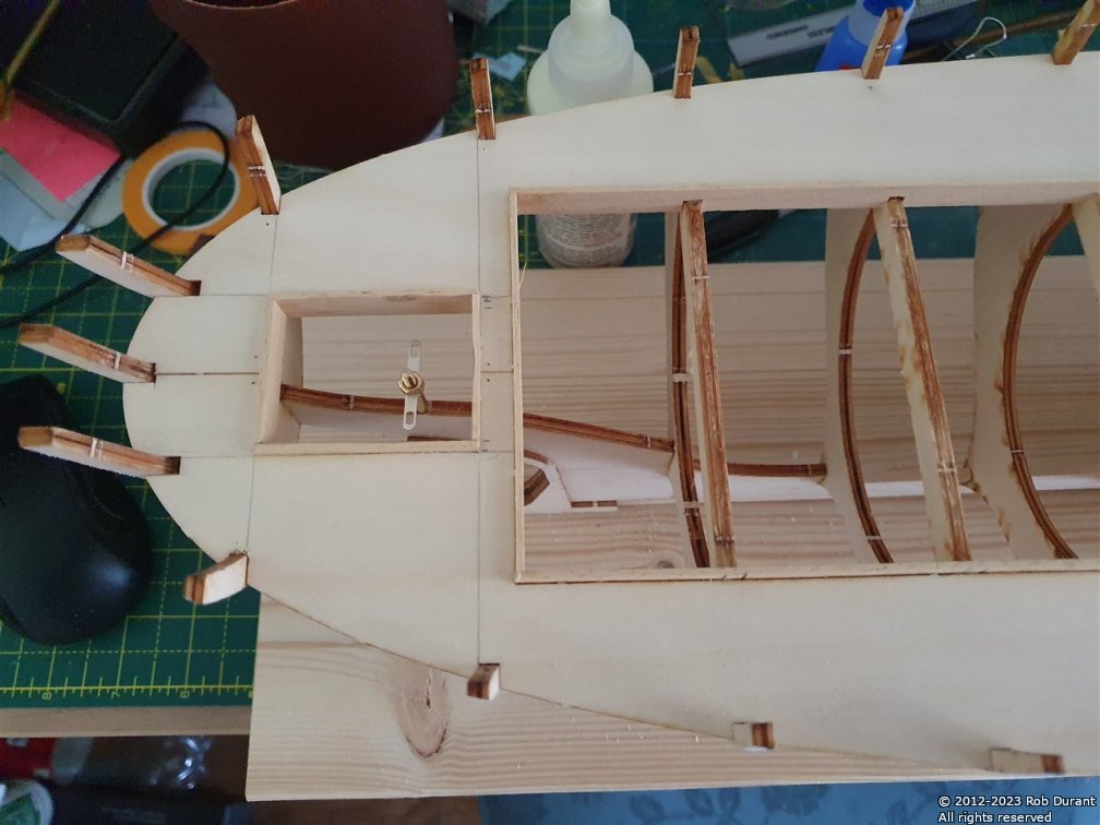
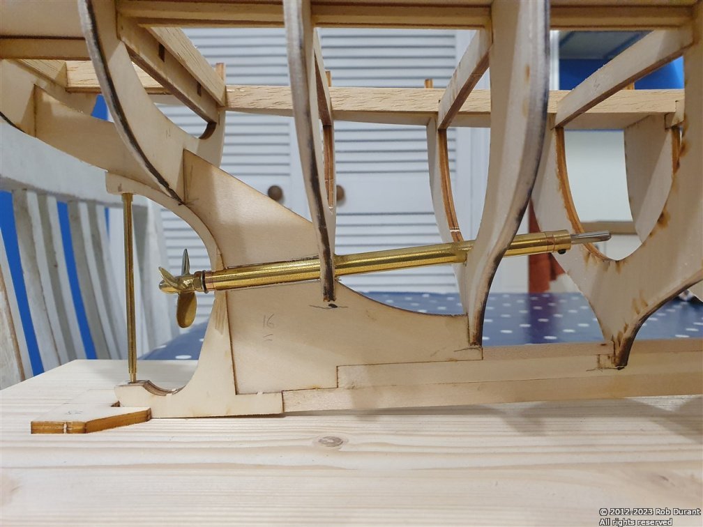
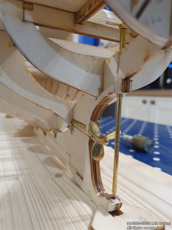
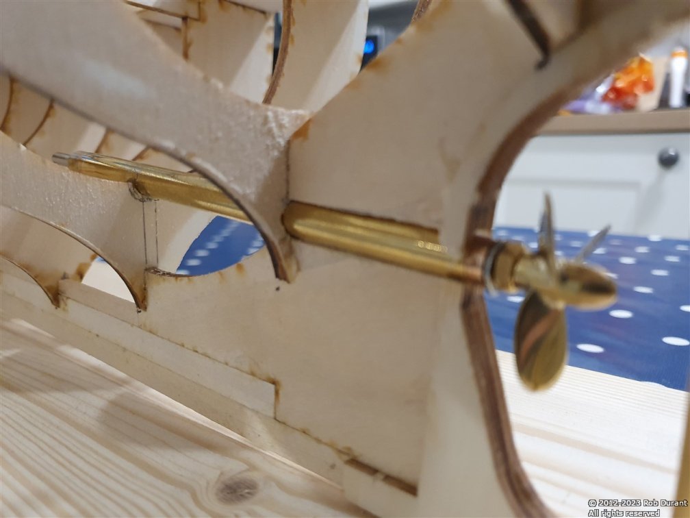
I had a little time to spend on Nordkap today, so here's an update. I've added access to allow the tiller arm to be maintained without ripping up the deck, and begun installing the prop shaft and rudder shaft. A little fore-planning is required for the prop shaft, as I didn't want to install it and find that the motor was in a ridiculous position inside the hull (especially to find that it had to be mounted too low...) the flat surface where the prop shaft exits the hull gives some idea of the angle required. I replaced the prop shaft with a 5" M4 shaft from George Sitek, along with a brass prop... I mistakenly ordered a 32mm prop when I realise now I need a 38mm one (so the 32mm prop looks a little small in the photos)... but the updated prop has now been ordered and will replace the smaller one when it arrives. Here are some photos of progress... The tiller access... And the prop shaft... The next job will be to add doublers on either side of the tubes to strengthen them, and fix them permanently in place with epoxy. Thanks for looking in Rob
- 57 replies
-
- 6
-
-
- Nordkap
- Billing Boats
- (and 1 more)
-
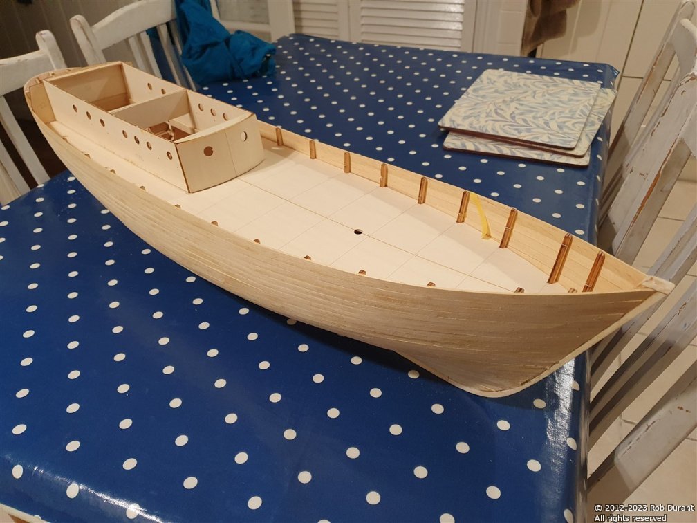
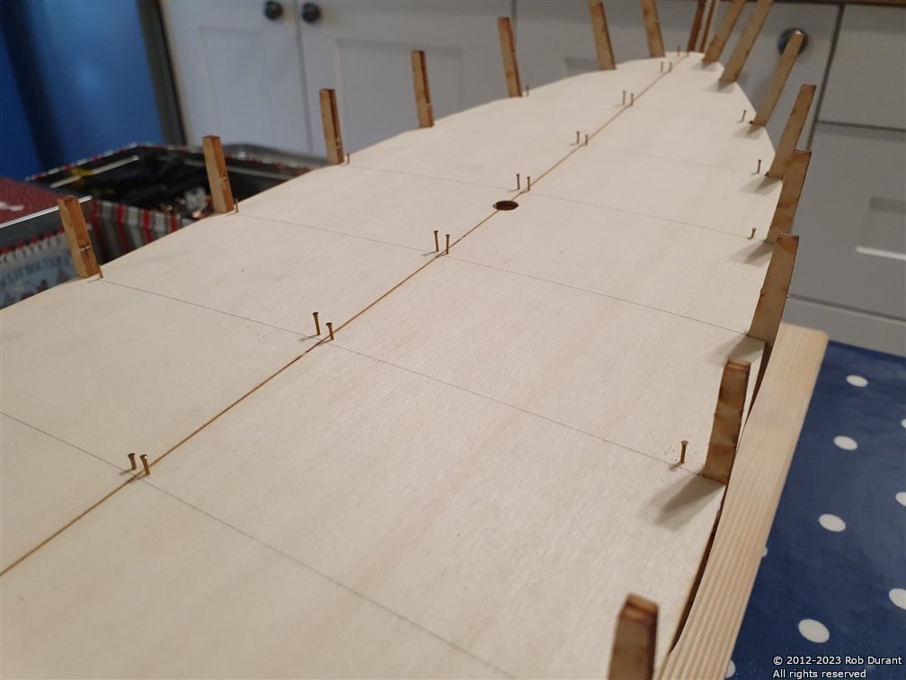
With the help of some of the planking pins, I glued the deck down. Once the glue was in place, I placed the deck, and the Aliphatic glue (Carpenter's glue) gave me enough time to predrill holes for planking pins, and secure the deck to make sure it was well in contact with all of the deck beams. Clamps were used round the inside of the deck opening. I left it overnight to set, and then pulled the pins back out with some needlenose pliers... nice and easy. And here's a different shot showing something of her lines... Thanks to those who've looked in
- 57 replies
-
- 4
-
-
- Nordkap
- Billing Boats
- (and 1 more)
-
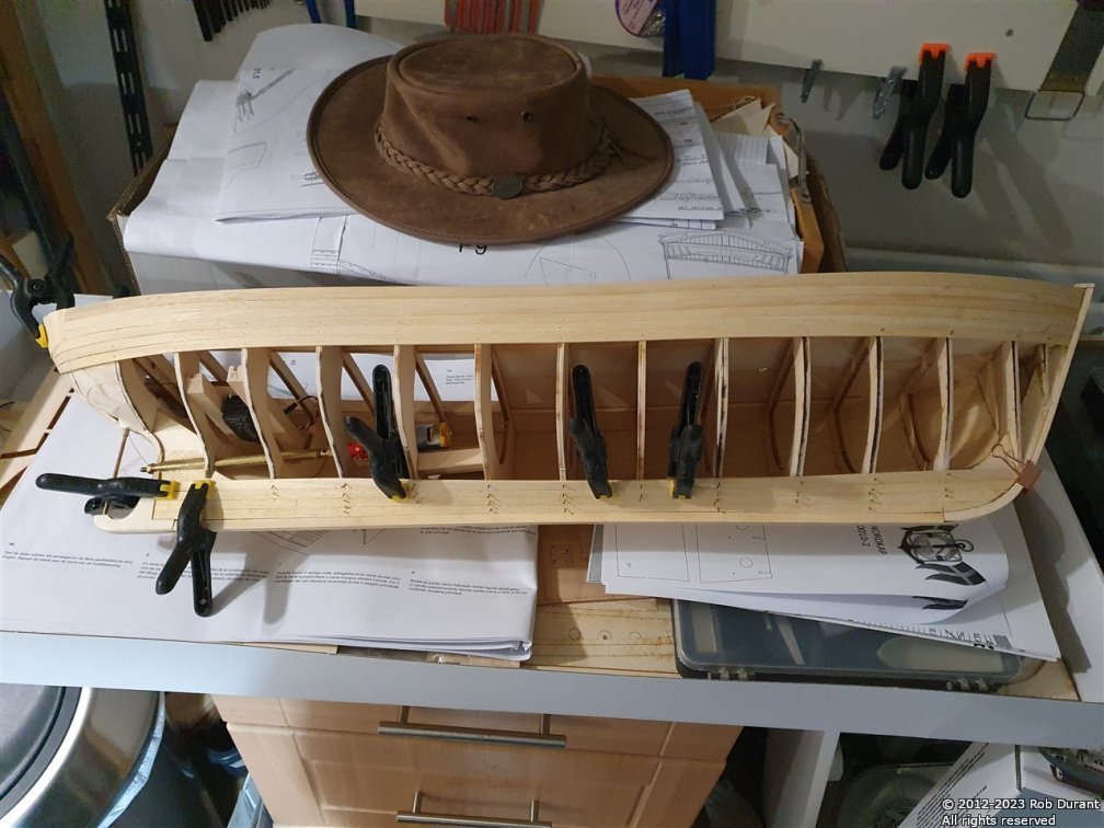
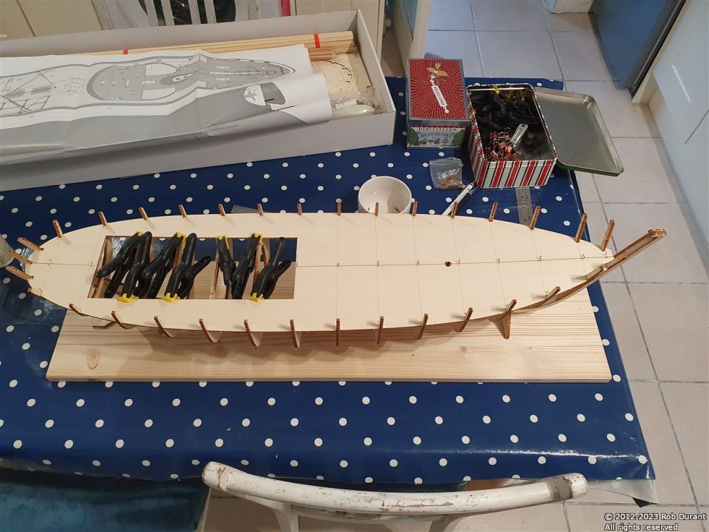
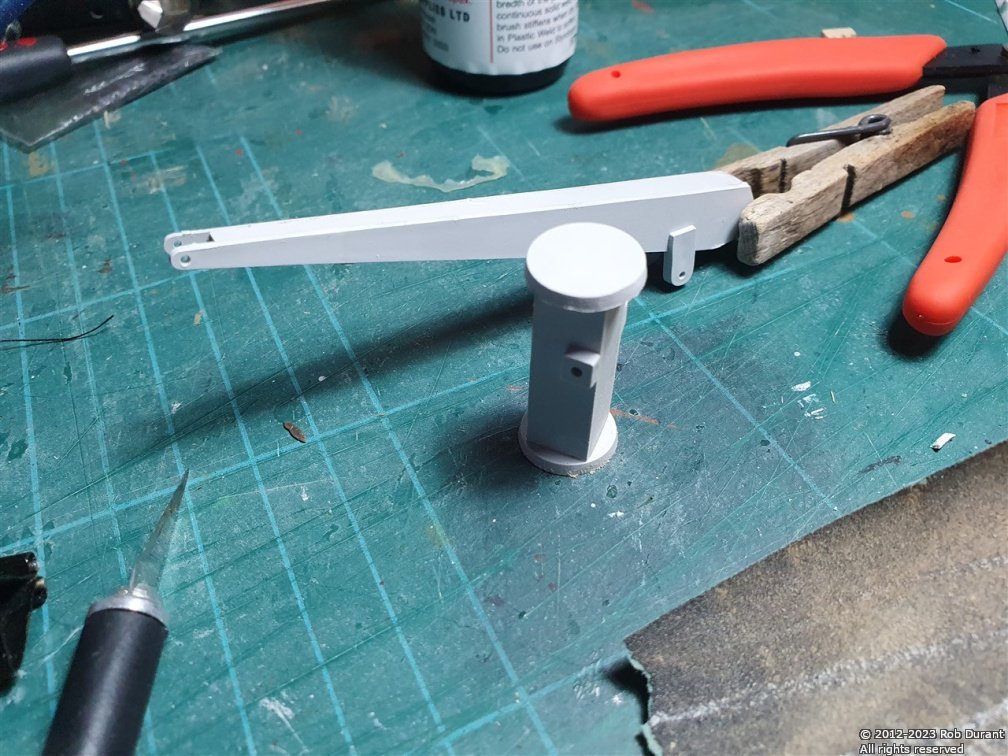
A big thank you to whoever fixed the title on this log... I've added the bridging pieces to the tops of the bulkheads and the stringers that run across the tops of the bulkheads to tie them together. The deck was added again while all of this dried to ensure that it was all lined up. It all seems to have gone quite cleanly. I also began to build the ship's boat davit while I was waiting for glue to dry. The photo below is after all the clamps were taken off...
- 57 replies
-
- 2
-
-
- Nordkap
- Billing Boats
- (and 1 more)
-
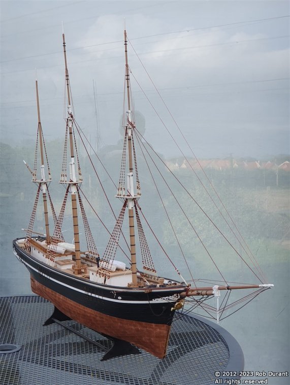
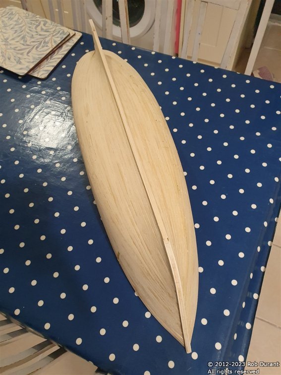
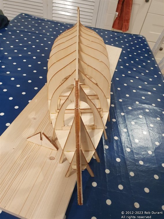
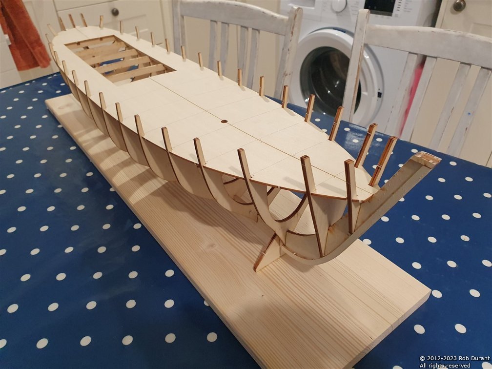
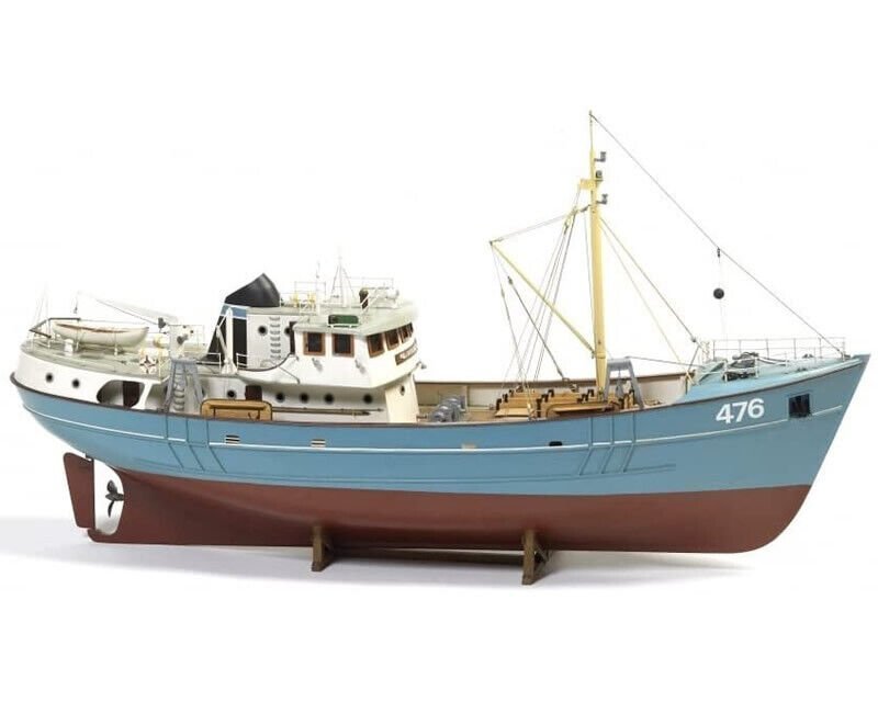
As I near the completion of Barque Stefano, I had a hankering to build something that was simple, where I could just follow the instructions, straight out of the box. Time will tell how closely I manage to do that, but having looked longingly at Nordkap as a teenager, she was the vessel I settled upon. Here's a picture of what she's meant to end up looking like Nordkap builds up into an 81cm l.o.a, 21cm beam vessel - so there'll be loads of room in the hull for all the radio gubbins. She's also small enough not to be too cumbersome to move around when building. I bought a new building board, and set about separating the laser cut frames from the "sprues". Then I looked at the plans and noticed some strange discrepancies... There are two sets of measurements on plan 1 - the first shows the gaps between the forward extents of the frames (4-7) - this should measure up to 159mm. A second set of measurements show the filler blocks that will sit on top of the keel - these are 48mm, 50mm and 50mm - 148mm, leaving only 11mm for three frames - but the frames are 4mm at the least - closer to 5mm in fact... The instructions simply say that the frames are "quite vertical" and then leave the builder to work it out. Instead of guessing, I decided that using the deck would be a neat way of ensuring that the frames were essentially in the right position, so this part was cut out as well and used as a guide to get the frames in the right place. So... so far I've fitted the frames, and added the blocks in between - which have all turned out to be around the 48mm mark. This _may_ come back and bite me later, but I feel much more confident knowing that the deck fits with the frames in their locations, than simply hoping for the best. The observant among you may notice a curvature of the keel (higher in the middle than at bow and stern - it's around 4mm, although it looks worse, perhaps because of lens distortion in this photo) - ironically, having cut the keel parts to be 55cm and 52cm respectively, I now realise that these are perhaps slightly short for the deck... removing the deck after gluing the frames in place got rid of this curvature entirely, and so I probably will need to modify the deck a little down the line, but that's fine - it'll be millimetres here and there, not centimetres, and the hull will be the right shape. The next step is to add the stringers along the bulkhead tops, and as I do that I can ensure the keel is straight. I'm not worried about modifying the deck to fit, I just wanted everything to be in the right ballpark. I've also added the doublers that create something of a rabbet at bow and stern. More soon Rob

- 57 replies
-
- 7
-
-
- Nordkap
- Billing Boats
- (and 1 more)
-
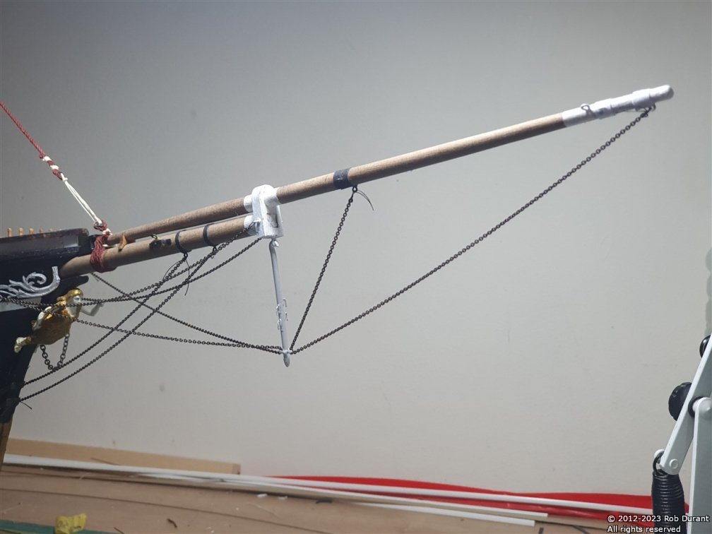
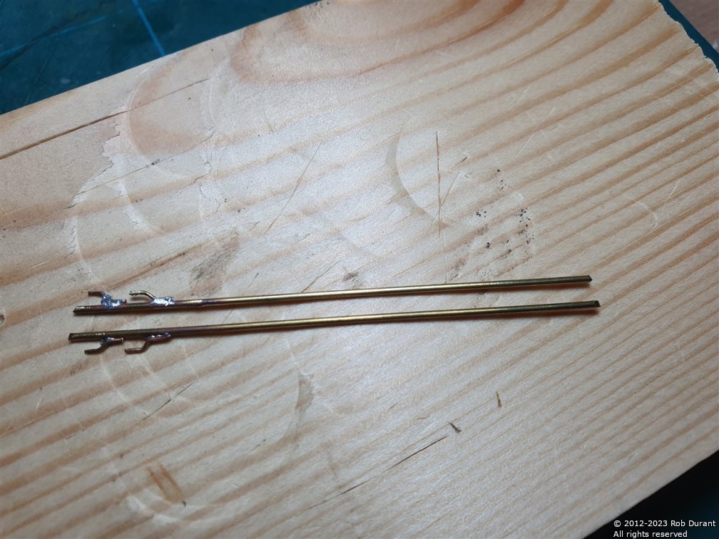
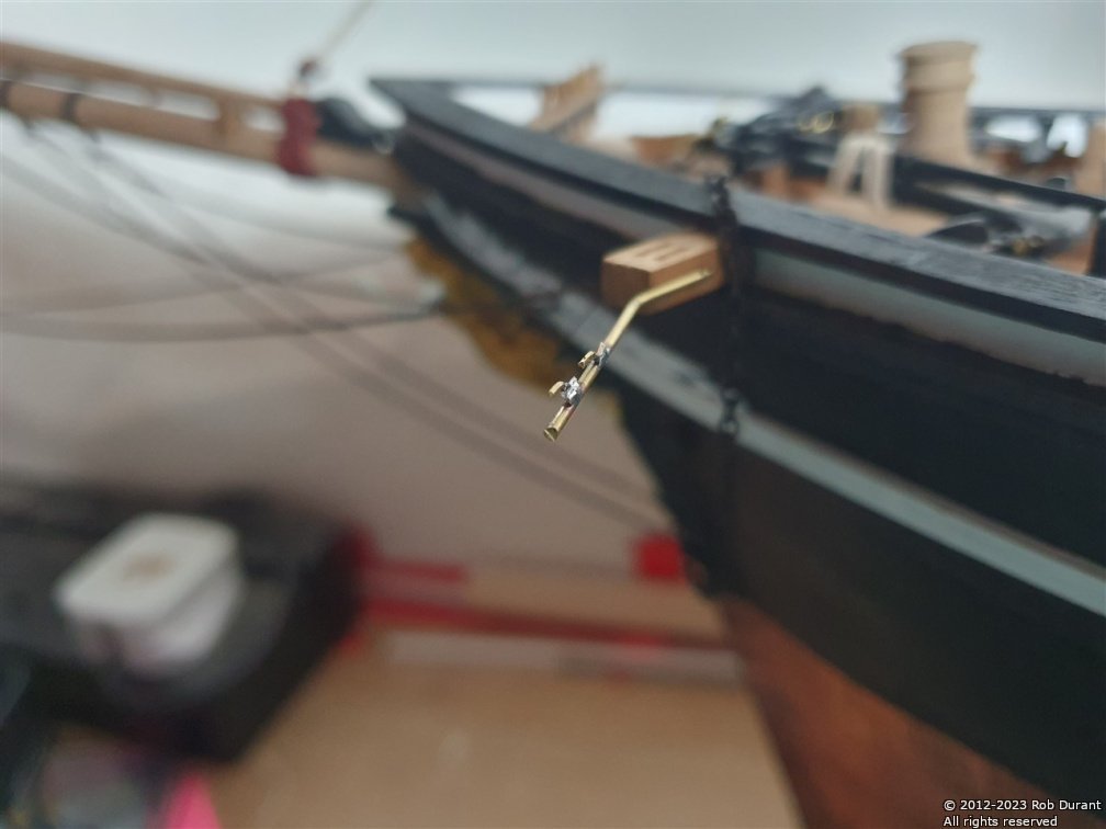
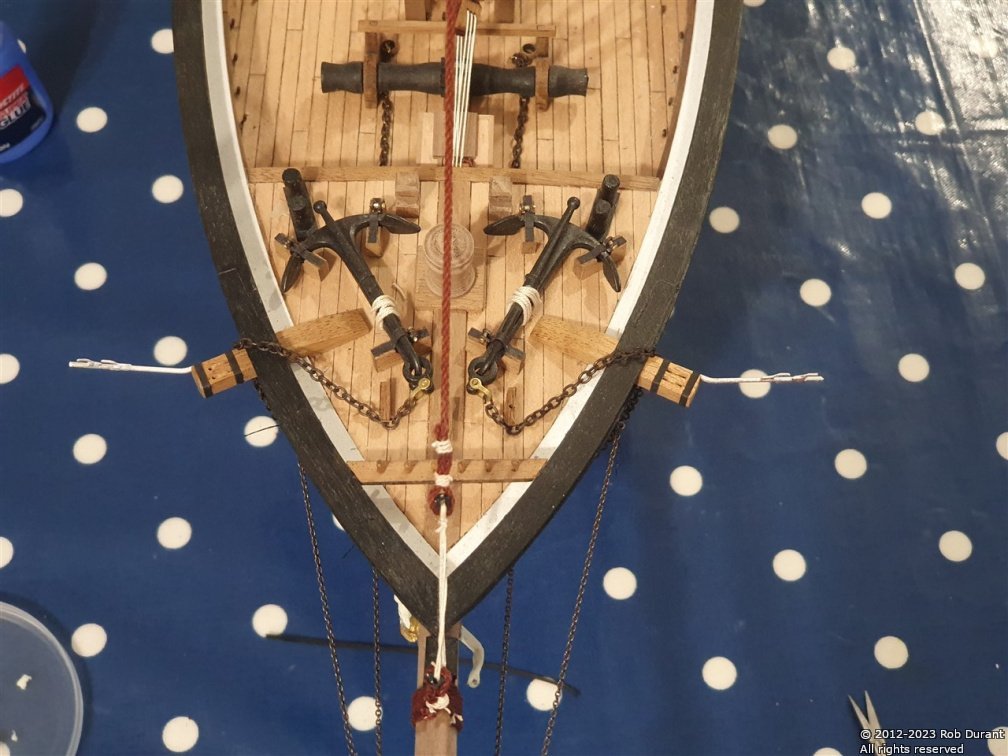
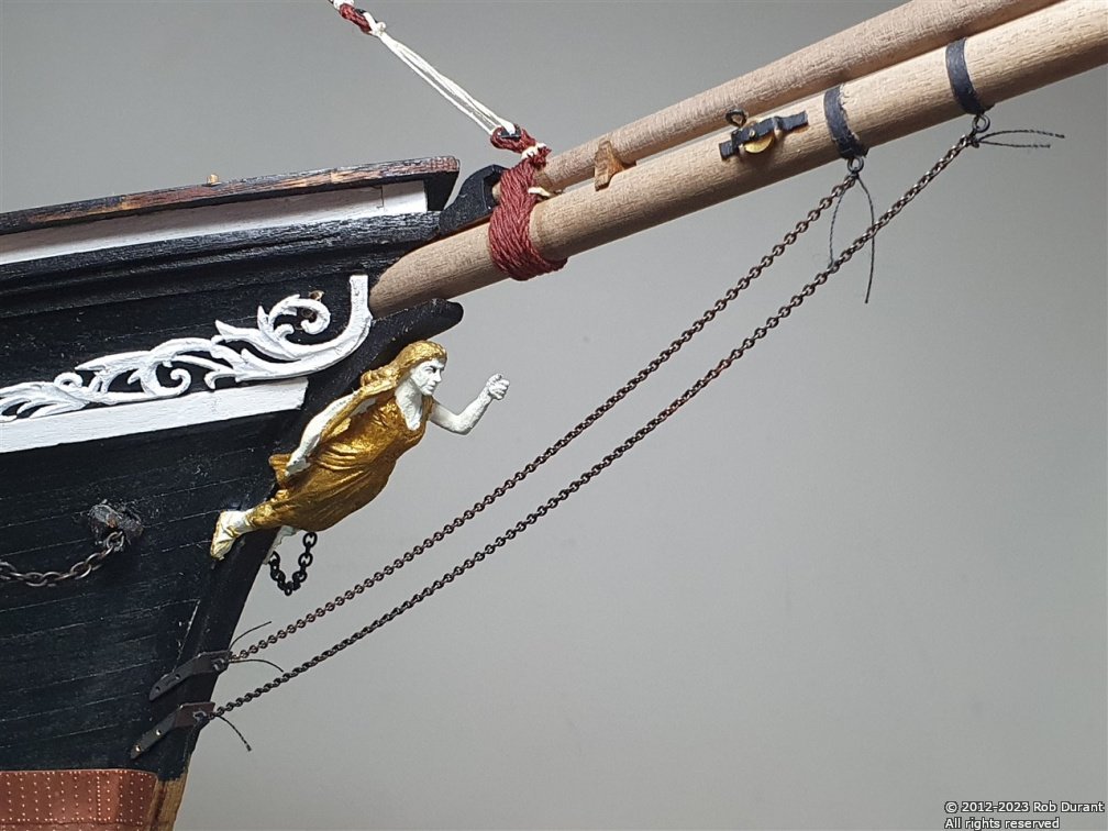
Over the past few days, I've made good progress on the bowsprit rigging, including making the "whiskers" on the catheads, which were soldered from 1mm and 0.5mm brass rod, and then sprayed with white primer. The topgallant shrouds were also set up. I wanted to use black card for the strapping on the cathead whiskers, but also wanted them to be strong enough to withstand knocks and bumps, so rather than simply stopping them at their inboard extent, I have them bending 90 degrees, and fitting into a hole drilled into the cathead itself. This provides lots of strength, and I'm confident they'll withstand gentle knocks... Hopefully I'll avoid anything more dramatic. Adding the "hooks" for the rigging first... Then bending them to fit... and trial fitting them in the holes drilled in the cathead. They were fitted before I bent them vertically up, so that I could ensure they both bent up the same amount... and black card was added to simulate the metal straps... The finished article, once rigged... (rigging required that I make some 0.5mm rope, and then stained it... For those interested (and as an aide memoire for myself, it was made with #100 DMC Cordonnet crochetting thread, 1x thread per strand, 3x strands). The rigging was fastened using #50 DMC Cordonnet thread, and fixed in place with watered down PVA. And as mentioned at the beginning, I've also rigged the top gallant shrouds... Rather than adding deadeyes, I've copied the way these were rigged on my Ethalion... It's nice to feel that progress is being made.
-
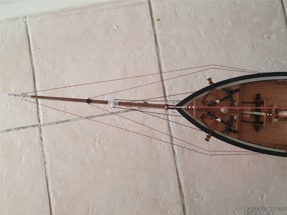
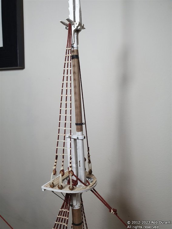
Topmast shrouds and ratlines are complete. I've been doing a little work on the bowsprit, adding the inner and outer bobstays using the kit supplied chain, which was chemically blackened. The chains were attached using black thread, which will be trimmed one I've put some glue on it to stop the knots coming undone.
-
Not much to report, but I've finished the ratlines on the Main topmast... Onto the Mizzen topmast now...
-
Thank you @rwiederrich - yes, it's definitely a personal choice, and not one that's historically accurate, perhaps. I just like the look
-
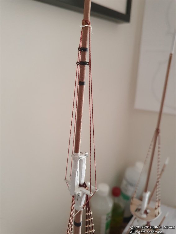
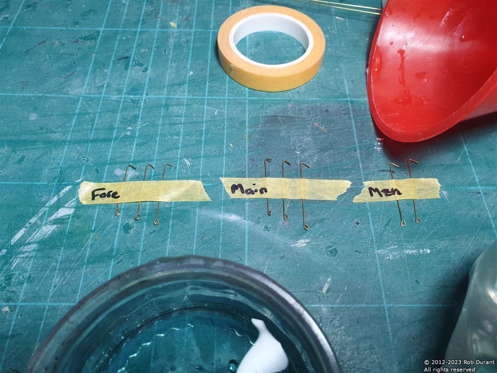
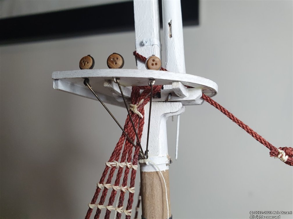
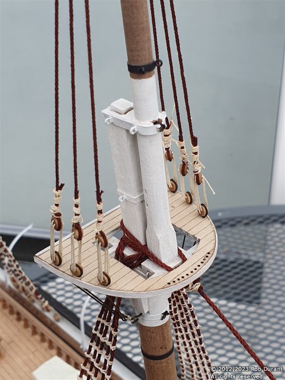
Okay - time for a short update... I've added the futtock bars - it took me a lot of head-scratching to work out how to do this neatly, but I ended up using 0.5mm brass wire, with a loop at one end, that was tied to an eyelet in the mast, having hooked the other end through the eye in the bottom of the deadeye strop... They were tested for size, then blackened before final fit. The parts... And the fitting... And then I went on to put on the topmast shrouds, and I've begun the ratlines... Progress is being made As before, the ratlines are DMC Cordonnet #20 Ecru thread. The same stuff I use for rope-making. It's lovely stuff to use for tying ratlines - very forgiving, and once brushed with watered down PVA, I've had no problems with knots coming undone. Once the topmast shrouds have their ratlines, I'll need to add the futtock bars for the crosstrees on the fore and main masts. Thanks for looking in and taking an interest. Happy building Rob
- 286 replies
-
- 12
-
-
And a last post for today.... I've roughly shaped the bow, changed the lighting, started playing with moving the camera, and added some texture...