robdurant
-
Posts
843 -
Joined
-
Last visited
Content Type
Profiles
Forums
Gallery
Events
Everything posted by robdurant
-
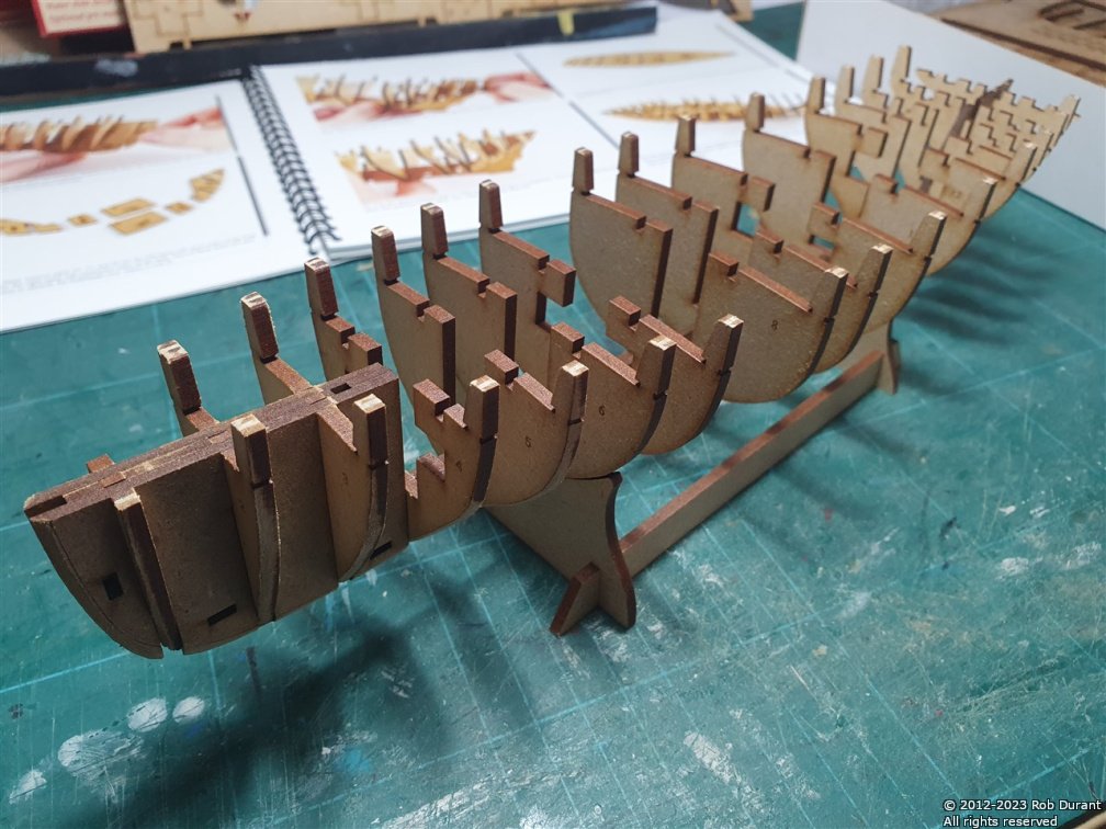
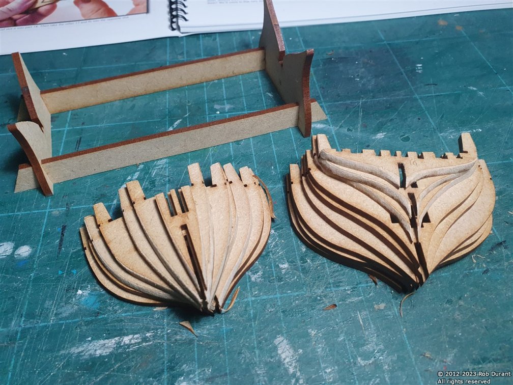
 A promising start this morning. As with the Lady Isabella, this kit is exquisite. The parts fit is immaculate, the parts clearly labelled, and easy to find, and the instructions very clear and simple. For anyone setting out into building model boats for the first time, I'd recommend going gently with the sanding of the MDF bulkhead parts... you'll probably end up needing to take them back further than you think, but slowly and carefully is the way forward. Vanguard provide lines to show where they need to be sanded back to, and plenty of great full colour pictures at ever stage to guide you through the process. (And no, I'm not being paid by Chris at Vanguard to write these things - I'm just enjoying this kit)... Anyway - here's progress so far. Bulkheads cut out and the initial bevelling done (with a combination of scalpel and sandpaper stuck to a board... And assembly - all dry-fit at this point. The reinforcing parts on each side at the bow will be stuck in and then tabs placed through, ensuring that they're in precisely the right position. Assembly was achieved with a good tight fit of all parts straight out of the box. Gently supporting the parts and tapping them into place worked wonderfully. Right... that'll do for today Thanks for looking in, and for all the likes and encouragement. Rob
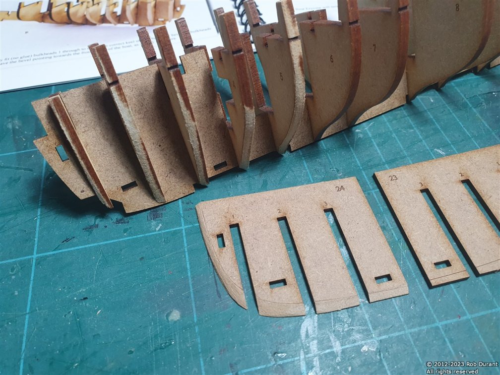
- 47 replies
-
- 3
-

-
- Erycina
- Vanguard Models
- (and 1 more)
-
Thank you, Chris
-
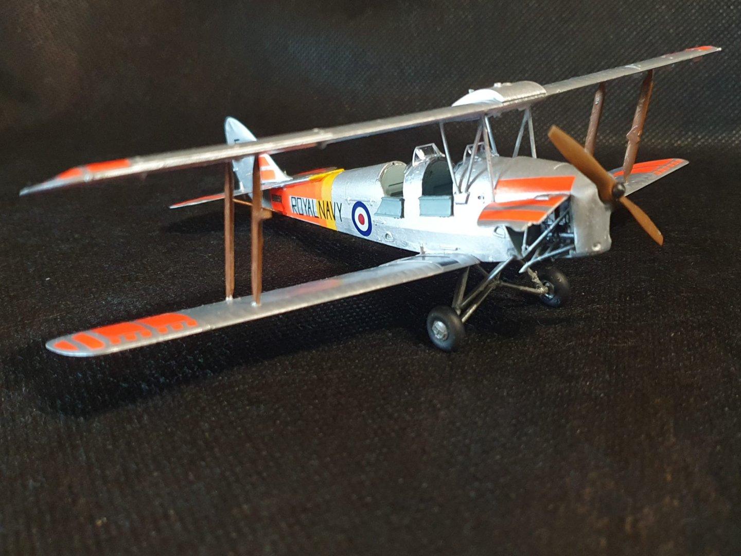
Okay - so having had my immune system attack my brain (explained here... An enforced and hopefully not permanent hiatus), I'm currently unable to think at the kind of level required to make any progress on the projects I had going before (Barque Stefano, HMS Bristol (1775), and Nordkap). To be honest, I can't quite believe I ever even attempted them at all! I'm now having to learn a whole bunch of stuff all over again (new neural pathways, apparently!), and this build is part of my exploring what I'm able to do now Progress is encouraging! Over the past month, I've gone from managing one step of a lego model per day, to being able to use a scalpel again without terrifying everyone within arm's length, to building and painting the brand new 1:48 Airfix tiger moth kit (picture below). I can recommend that kit, btw... it's a fun build! (And no, I didn't attempt the wires between the wings... ) Now, I'm excited to be taking on this beautiful kit as the next step. Having built a model of Lady Isabella before (below), I knew the instructions, kit design and support from this forum, and the simplicity of the build as a whole would be the best shot I have at getting back into this wonderful hobby! So thank you, Chris of Vanguard Models for such an excellent kit! It will be interesting to see how close I can get to this in this new build... I'm hoping to invest in the more detailed sails for Erycina (a rough set are included with the kit, but I can confirm that they aren't a patch on the sails that I purchased alongside Lady Isabella, which I presume are of the same quality as Erycina's separately sold sail set). That Vanguard sells them separately also means I can get them as a separate purchase and spread the cost . Hooray! There are already lots of excellent build logs of this kit, so I'm not expecting to exhaustively cover every step, but I will share my thoughts on it, and if I digress from the kit (not the plan!), I'll note what I've done and why, and you are very welcome to follow along and comment if you'd like to. Anyway - Erycina arrived today, and I shall get stuck in tomorrow. Thanks for reading this far. I'm sure progress will be slow! But slow and steady is just fine More sleep, first! Updates to follow. Rob
- 47 replies
-
- 8
-
-
- Erycina
- Vanguard Models
- (and 1 more)
-
Their final appearance suggests that they were put together by the people on the factory floor who'd spent all day doing it and knew exactly what they were doing... I can't pick up any sign of a struggle... really beautiful work! As an aside, my nan was one of those people on the factory floors... she was building Lancaster bombers, though.
- 126 replies
-
- 11
-
-
Thanks, Jason. Progress is slow but encouraging. Hopefully I'll get back to a place where I can continue this model, but it's well beyond me at the moment until then, I walk past it every day and marvel that not so long ago, I did that! 😆 Great to see you making headway on your stunning Artois class. Rob
-
She certainly is a handsome subject. I wish you all the best as you set out to build her.
-
Hi all. Apologies that this build has stalled from my perspective. The post here will explain Blessings on you all. Rob
-
Hi all. Apologies that this build has stalled from my perspective. The post here will explain Blessing on you all. Rob
-
Hi all. Apologies that this build has stalled from my perspective. The post here will explain Blessing on you all. Rob
- 57 replies
-
- 1
-

-
- Nordkap
- Billing Boats
- (and 1 more)
-
Thanks 😊 I've been following along with interest but have not been well recently. Lots to give thanks for, though, so I shall just wait patiently until it's time to pick up these threads again. The boats are patient, thankfully.
- 57 replies
-
- 2
-
-
- Nordkap
- Billing Boats
- (and 1 more)
-
You can find it here... hope it's helpful. Any questions, just ask. https://modelshipworld.com/topic/26538-free-picture-resizer-application-i-programmed-to-solve-those-image-rotation-woes-microsoft-windows-10-and-11-only/
-
Hi Kevin, This is a lovely, welcoming and helpful community. I could not have done half the builds I've done without the support I've found here. Good to have you here. Do consider starting a build log and showing people where you're up to. You'll get more input that way and it will provide a place to ask any questions you might have and get those answers Rob
-
Congratulations on your retirement. It's great to see progress on this model being made, and I hope you find great joy as you adjust to this new season of life.
-
Having built a vanguard model, and having almost finished MarisStella's largest model to date, I can say that the instructions are like night and day. Vanguard hold your hand throughout, making even the most complex of their models something that can be achieved with perseverance and patience. MarisStella provide many plans, but drawing them together and planning a build sequence or working out what tool to use for what task is left in many ways to the builder. Both fun to build (if you're happy to invest all the time required for the choice you make), and neither approach is wrong, but I would definitely expect a far steeper learning curve with MarisStella if it's similar to Barque Stefano.
-
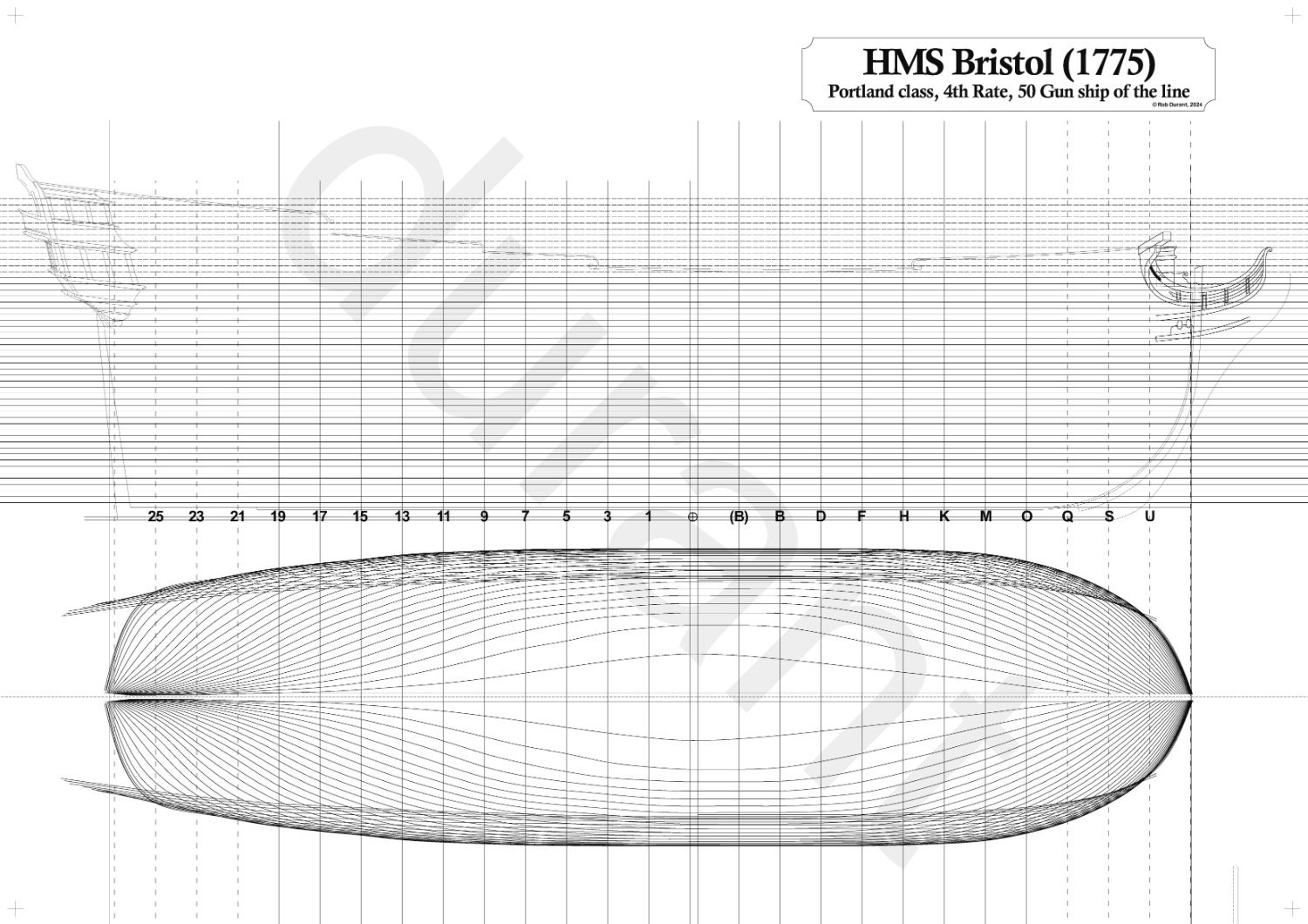
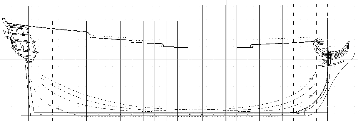
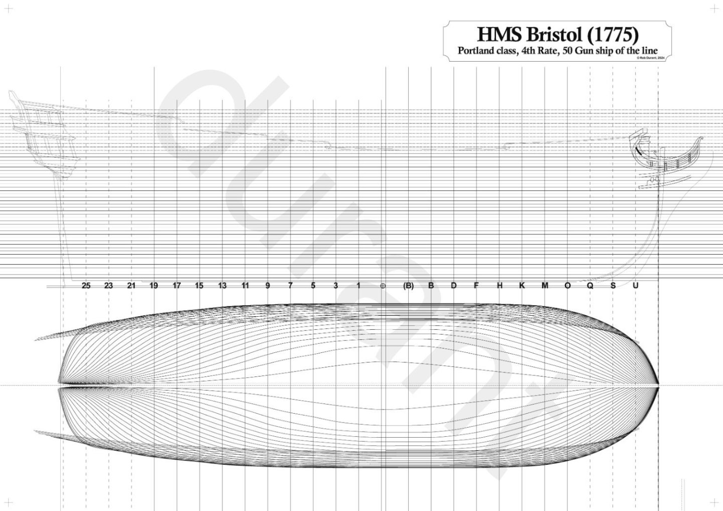
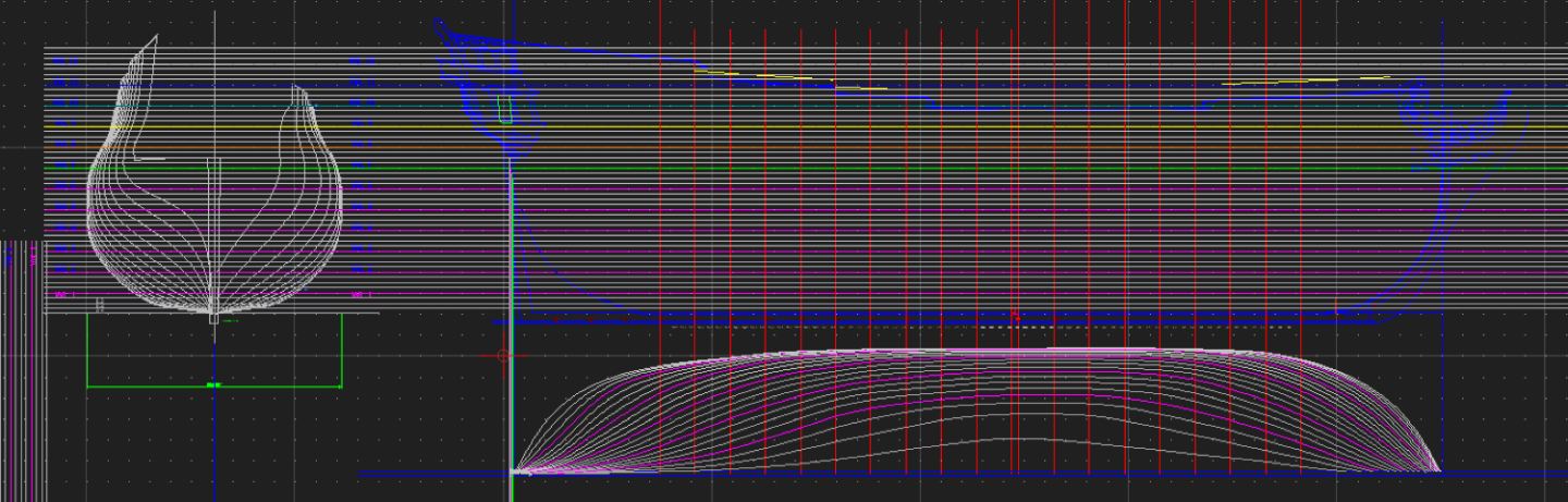
Finished the waterlines, and here are the buttock lines. Only very minor changes, and they look pretty smooth, so I think I'm happy to start sketching out the square frames...
-
Thanks - That's the next task after I finish these waterlines... The first attempt without the interpolation looked fine, but I've moved things since then, so I'll go over it again. Here's a snapshot of progress to date... I'm looking forward to the bit where I can say I'm happy with these lines, and I think I'm edging closer.
-
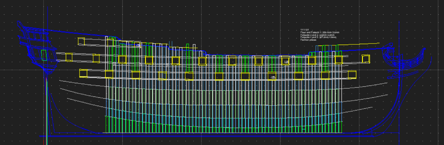
A brief update to say that I haven't stopped all progress on this project, but there hasn't been much to show. I've been fine-tuning the CAD plans, interpolating between the waterlines, before I begin to loft the frames. It currently looks like this... I'm beginning to have confidence that these lines will make a good-looking hull. I still have to add interpolated lines above where the tumblehome begins... that's the next step. I've also redrawn all of the square frames, so that they are one of three "sides" (depths of wood front to back) - I hope this will make the final construction much more efficient. Once I'm happy with the lines, I'll add the canted frames, too. Thanks for looking in, and for all of the fascinating discussion. My efforts must appear very stone-age, but I'm having fun, and enjoying the pace I'm working at, so I figure that's a win! Stefano's beginning to reach the final stages (just running rigging to do) so I'll have more time soon - and hopefully some space on my build desk again! Rob
-
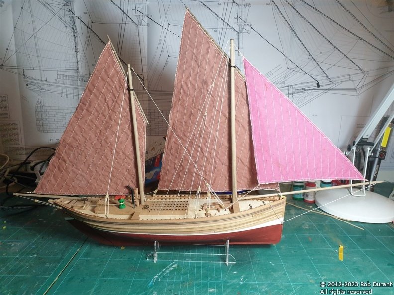
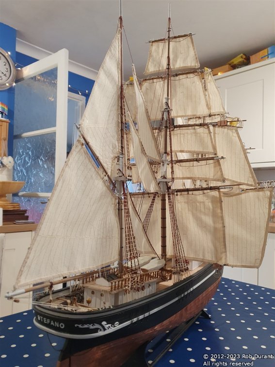
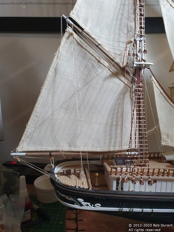
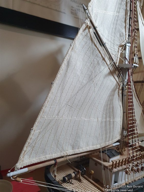
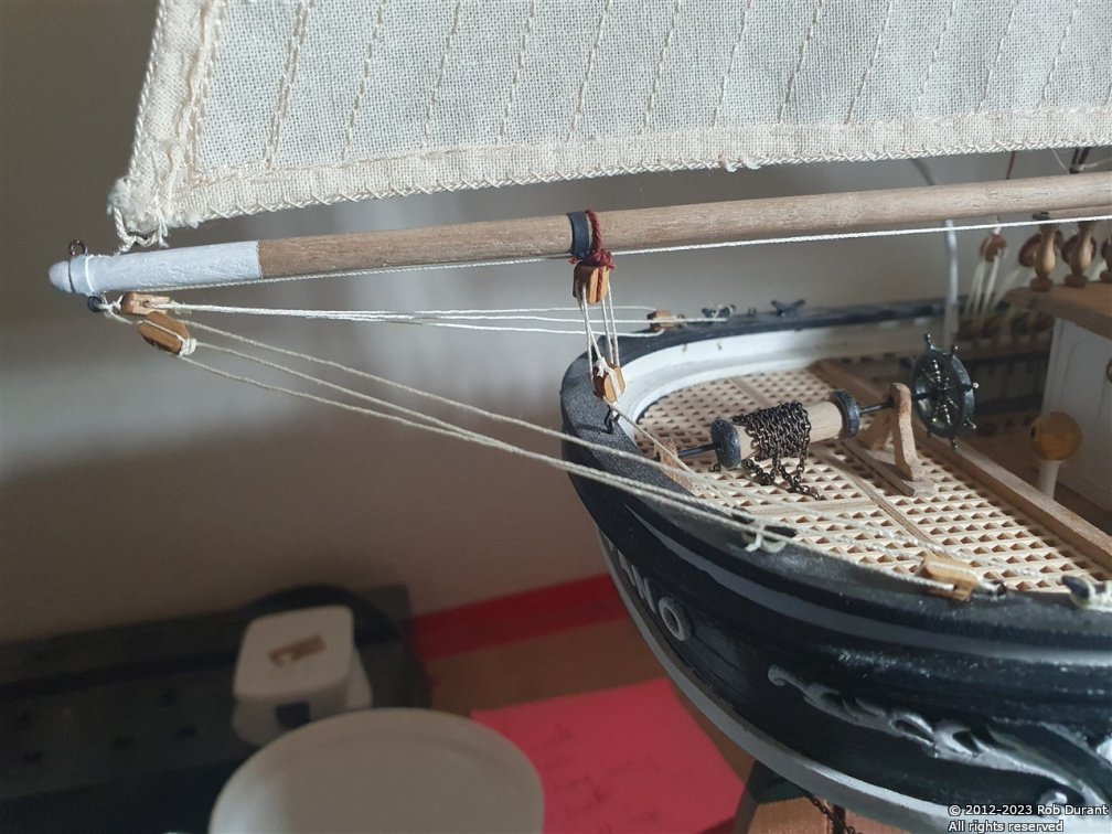
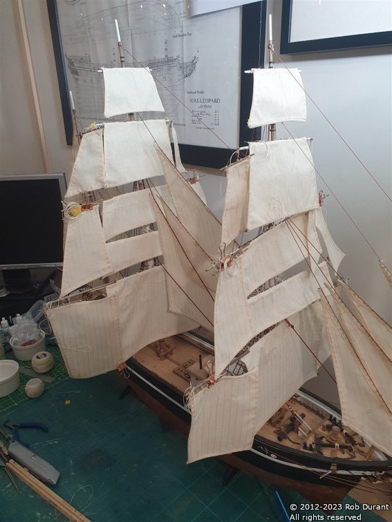
A very quick update, and an opportunity to say a big Happy Christmas to everyone Immanuel - God is with us. I've completed the task of fitting out the yards, and bending the sails to them. And now, I've begun to add the running rigging, starting at the mizzen mast, and moving forward. Now that I'm well into it, I'm beginning to understand the plans. It's necessary to reference various different plans to see all of the runs and belaying points. This means the task is best down with a big table spare... The kitchen table works for me, but it does mean that it's not very easy to proceed when family are around for Christmas - a nice problem to have ! Here are some pictures of progress so far...
-
Somehow I found myself doing two builds where the instructions were much more basic than my previous models, and it does mean that more of my energy is spent on convincing myself to keep plugging away than it was on the builds I did before. I do find I get satisfaction from working out my own solutions, so it's just part of the process. Definitely a word to the wise for those setting out, though. There are various stages where the Nordkap simply leaves you to work it all out for yourself.
- 57 replies
-
- 1
-
-
- Nordkap
- Billing Boats
- (and 1 more)
-
What a lovely present. I'm in the middle of building a Billing Boats model (Nordkap), so I'll pull up a chair and follow along if that's okay. Looks like you've made a good start already, and now I've seen your last build, I'm sure you'll come out the other end with a fine model!
-
Hi Halsey Welcome to the forum. It's a great place to get encouragement, support and advice, and you'll find that opinions vary about whether glassing is necessary for an RC boat to be reliably watertight. Having used Eze kote I can confirm that it's lovely to use. It sets up good and hard, cleans up easily and leaves a relatively smooth finish. A little sanding would take out the final brush strokes, but as you say on a model such as this a few marks do not necessarily take away from the working boat feel. My small experience so far suggests that the hull is comfortably watertight enough for occasional sailing. I won't be on the water every weekend, so I don't feel the need to make the finish as robust as others may? My tests in the bath tub have been very encouraging with no sign of water ingress at all. I haven't noticed any scratching or marks in the eze kote finish, and the vallejo acrylics have taken well over the top, with no sign of weak adhesion. Until I've finished the boat and sailed for a season that's about as much as I can tell you, but early signs are very promising. You are doing a find job with your model. I hope you will start a build log so I can learn from you as well Any other questions, do ask away. All the best, and a very Happy Christmas to you. Rob
-
Hi Paul, I'm glad if my ramblings are helpful. It's a nice kit to build although there are points where a little more detail would be appreciated in the plans. I've realised that the layout of the parts that build up the superstructure is shown on some 1:1 sheets. Might help you out where I guessed. Nordkap does make up into a handsome model, and I hope you get a lot of enjoyment as you build her, as I have. You'll be able to skip some of the steps I've taken if she's to be static. Rob
-
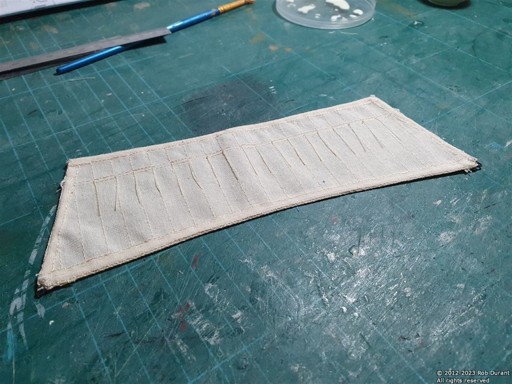
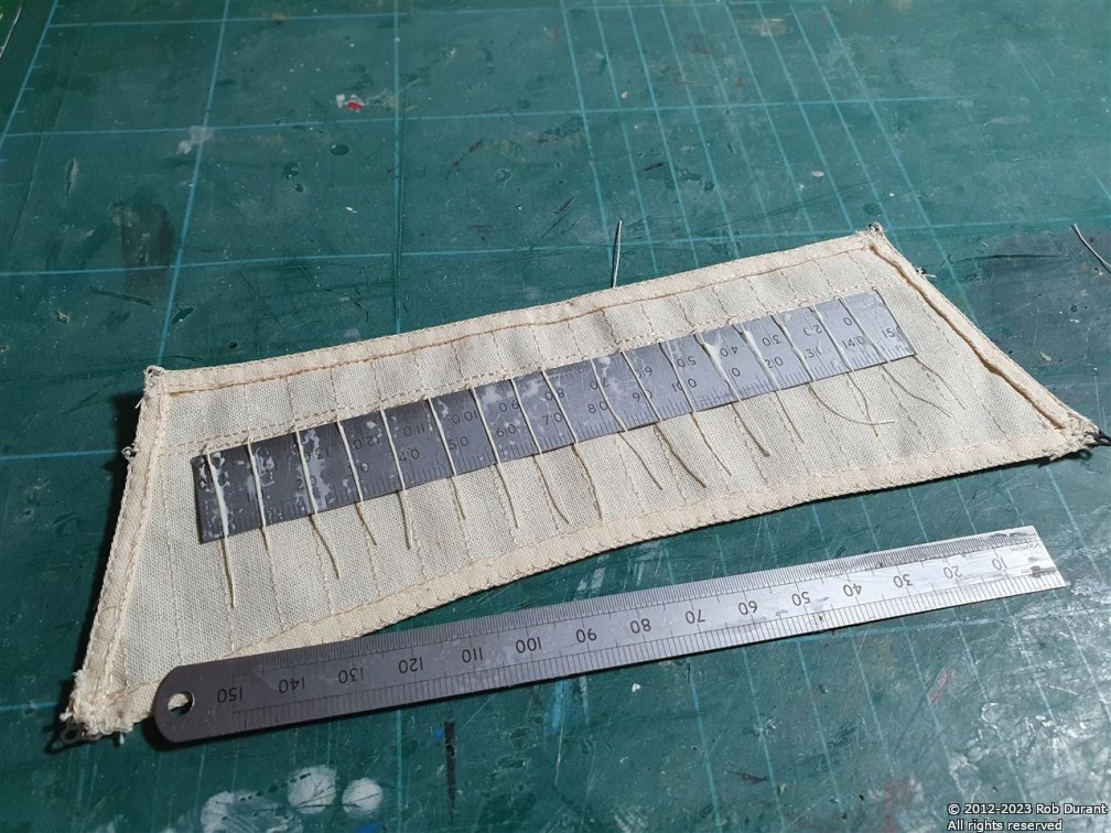
Thanks, @BobG, @gak1965, @AJohnson, you're very kind. I feel surrounded by masters, here... but I'm pleased with how my bodging is coming along! I managed to add the reef points to the fore upper-topsail, which is the last sail to need reefing points, so that was a nice milestone to reach. Next is to add the eyelets and blocks to the fore upper-topsail yard ... am I the only one who finds drilling holes all over the yards a fiddly and frustrating job? I think I've probably described the process of the reefing points before, but just in case, it's #100 DMC Cordonnet crochet thread, with a knot in it (one knot is plenty), then threaded through the sail with a needle. Once through, it's cut off with a couple of inches to spare. When all done, I place a metal ruler beneath it, and use watered down aliphatic glue (Carpenter's glue / yellow glue) to stiffen the thread, and line it up vertically. Once fairly dry, it's cut to length (the width of my wider 15cm steel rule) and another dab of watered down PVA fixes the end in the right position on the sail. The sail is then turned over, and the process repeated. The finished article... I am glad to have these done. Thanks for all the support and encouragement Rob