
HOLIDAY DONATION DRIVE - SUPPORT MSW - DO YOUR PART TO KEEP THIS GREAT FORUM GOING! (Only 13 donations so far - C'mon guys!)
×


robdurant
-
Posts
842 -
Joined
-
Last visited
Content Type
Profiles
Forums
Gallery
Events
Everything posted by robdurant
-
 The following are the low-res copies that RMG (Royal Museums Greenwich) have uploaded to Wikimedia Commons as public domain images, and I'm putting them here as they'll help me as a reference to refer back to as I continue with the build. The details of each image are below them, along with a link to the image on the RMG website for those who might wish to purchase a high-res copy. What is immediately apparent is that there's a startling amount of information still available about this ship. When we look closely we realise that there's a history to be unpicked here, as well, since Bristol became a prison-ship in the 1790s and some of the plans below show modification made for that purpose. Clearly some careful study is required. https://prints.rmg.co.uk/products/plan-for-bristol-1775-j3857?_pos=1&_sid=c2ca144bb&_ss=r J3857, ZAZ1751 Plan for 'Bristol' (1775) - Scale: 1:48. Plan showing the quarterdeck and forecastle, and upper deck illustrating the cabin arrangements on Bristol (1775), a 50-gun Fourth Rate, two-decker, as built at Sheerness Dockyard. Signed by George White [Master Shipwright, Sheerness Dockyard, 1773-1778]. https://prints.rmg.co.uk/products/plan-showing-the-orlop-deck-for-bristol-1775-j3855?_pos=2&_sid=c2ca144bb&_ss=r J3855, ZA1755, Plan showing the orlop deck for Bristol (1775) Plan showing the orlop deck for 'Bristol' (1775), a 50-gun Fourth Rate, two-decker, as fitted at Chatham Dockyard as a Prison Ship. Scale: 1:48. Signed by Thomas Pollard [Master Shipwright, Chatham Dockyard, 1793-1795]. https://prints.rmg.co.uk/products/plan-of-the-starboard-side-of-the-head-for-bristol-1775-j3853?_pos=3&_sid=c2ca144bb&_ss=r J3853, ZA1752, Plan of the starboard side of the head for Bristol (1775) Plan showing the starboard side of the head for 'Bristol' (1775), a 50-gun Fourth Rate, two-decker, building at Sheerness Dockyard. The plan does not provide much information on the timbers used for the construction of the beakhead. Scale: 1:48. https://prints.rmg.co.uk/products/plan-of-the-spar-deck-and-upper-deckof-bristol-1775-j3856?_pos=4&_sid=c2ca144bb&_ss=r J3856, ZAZ1753, Plan of the spar deck and upper deck of Bristol (1775) Plan showing the spar deck (quarterdeck, waist, and forecastle), and upper deck illustrating the 'Bristol' (1775), a 50-gun Fourth Rate, two-decker, as fitted at Chatham Dockyard as a Prison Ship. Signed by Thomas Pollard [Master Shipwright, Chatham Dockyard, 1793-1795]. Scale: 1:48. https://prints.rmg.co.uk/products/plan-showing-the-gun-deck-lower-deck-for-bristol-1775-j3854?_pos=5&_sid=c2ca144bb&_ss=r J3854, ZA1754, Plan showing the gun deck (lower deck) for Bristol (1775) Plan showing the gun deck (lower deck) for Bristol (1775), a 50-gun Fourth Rate, two-decker, as fitted at Chatham Dockyard as a Prison Ship.Signed by Thomas Pollard [Master Shipwright, Chatham Dockyard, 1793-1795]. Scale: 1:48. https://prints.rmg.co.uk/products/plan-showing-the-gun-deck-lower-deck-for-bristol-1775-j3858?_pos=1&_sid=2820e0460&_ss=r J3858, ZA1750 Plan showing the gun deck (lower deck) for 'Bristol' (1775) Scale: 1:48. Plan showing the gun deck (lower deck) for Bristol (1775), a 50-gun Fourth Rate, two-decker, as built at Sheerness Dockyard. Signed by George White [Master Shipwright, Sheerness Dockyard, 1773-1778]. https://prints.rmg.co.uk/products/plan-showing-body-plan-sheer-lines-with-alterations-and-longitudinal-half-breadth-for-building-br-j3860?_pos=1&_sid=b8053f321&_ss=r J3860, Plan showing body plan, sheer lines with alterations, and longitudinal half-breadth for... Plan showing the body plan, sheer lines with alterations, and longitudinal half-breadth proposed (and approved) for building 'Bristol' (1775), a 50-gun Fourth Rate, two-decker. The plan includes a table of mast and yard dimensions. Scale: 1:48. https://prints.rmg.co.uk/products/plan-showing-the-body-plan-stern-board-decoration-detail-with-the-name-on-the-counter-sheer-lines-j3859?_pos=1&_sid=c30fbb098&_ss=r J3859, Plan showing the body plan, stern board decoration detail with the name... Scale: 1:48. Plan showing the body plan, stern board decoration detail with the name on the counter, sheer lines with inboard detail and figurehead, and longitudinal half-breadth for Bristol (1775), a 50-gun Fourth Rate, two-decker, as built at Sheerness Dockyard. Signed by George White [Master Shipwright, Sheerness Dockyard, 1773-1778]. And there are more Portland-class images… https://prints.rmg.co.uk/products/inboard-profile-plan-of-portland-1770-hannibal-1779-jupiter-1778-adamant-1780-l-j3574?_pos=3&_sid=178507300&_ss=r ZAZ1720, Portland (1770); Hannibal (1779); Jupiter (1778); Adamant (1780); Leopard (1790); Leander (1780); Europa (1783) Scale: 1:48. Plan showing the inboard profile for Portland (1770), and later for Hannibal (1779), Jupiter (1778), Adamant (1780), Leopard (1790), Leander (1780), and Europa (1783), all 50-gun Fourth Rate, two-deckers. https://prints.rmg.co.uk/products/framing-profile-of-hannibal-1779-jupiter-1778-leander-1780-adamant-1780-europa-j3575?_pos=2&_sid=ac99ef27f&_ss=r And a plan showing framing for Hannibal, Jupiter, Leander, Adamant and Europe - all Portland class ships. That last image is the one that convinces me that a fully-framed model is beyond me... but the lower frames might be possible. We'll see how we go. First up is to get the hi-res images I have so far ready to work from for CAD. Come hither, trusty scanner! As I go, I shall get more of these plans to help the process. I'm assuming that the process will reveal which plans are helpful when. And I love the idea of spreading the cost over the years instead of a single outlay.
 -
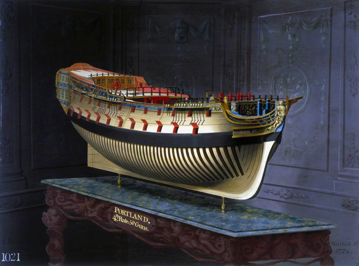
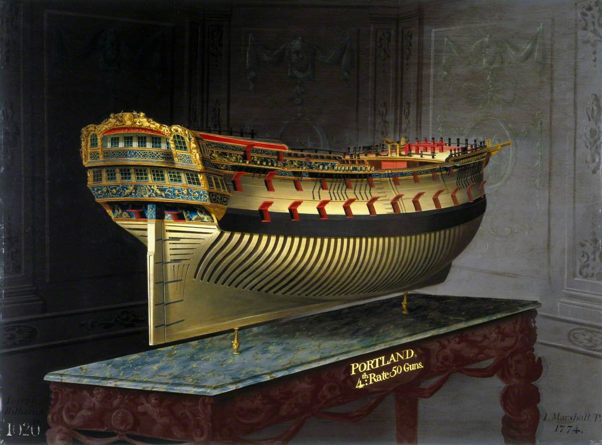
Hi all, I've often been very taken by the Joseph Marshall paintings, and in particular by the paintings of the admiralty model of Portland from the bow and stern quarters. (Here in low-res courtesy of Wikimedia Commons) That led me to explore the National Maritime Museum archives, and I came across the plans for HMS Bristol, her sister ship. That accompanied, with my stumbling upon RIf Winfield's book The 5o Gun Ship, which includes plans for another Portland class ship, Leopard meant I was well and truly smitten. A good number of plans survive for Bristol on the National Maritime Museum, and so, I figured (probably foolishly) that it would be wonderful to try and create as closely as possible the admiralty model shown in Joseph Marshall's paintings of Portland, but as her sister-ship Bristol. Having completed a model of HMS Diana, the Artois class frigate (as her sister ship Ethalion), and having made my way through a fair bit of Barque Stefano, both of which I have modified a fair bit as I've gone, I'm reasonably confident I'm up to the task of doing this as POB, but the big question is, how to recreate the frames... I don't think I'm up to fully framed yet - that will probably be the model after, so some POB / Joseph Marshall-painting-style-POF mash-up is the aim, with frames showing below the wales, and planked bulkheads above... As I'm designing it, I'm reasonably confident I can make this work, but there'll be plenty of planning before I make any sawdust. So. Right now, I have the following plan as a high res printout - this low-res version is from wikicommons (I couldn't stretch to the £100 license to buy a digital copy) and lots of low-res images. I'll add to the collection as I go. This is enough to begin planning internal structure. The full size plan is in 1:48, and it's stunning! From that tiny snapshot of history where the Admiralty had plans drawn up on completion of a ship, as well as at the beginning of construction - hence the decorations are all drawn out. So. This post is as much as anything a pin in the map - a starting point, and a statement of intent. If you'd like to join me for the journey you're extremely welcome. It'll be slow going, I'm sure, but it should be fun, and if it turns out anything like the picture in my head, it'll be really wonderful in the end
_RMG_J3859.jpg.98fd2a235bceabf6579a26769089dbc8.jpg)
- 55 replies
-
- 12
-

-
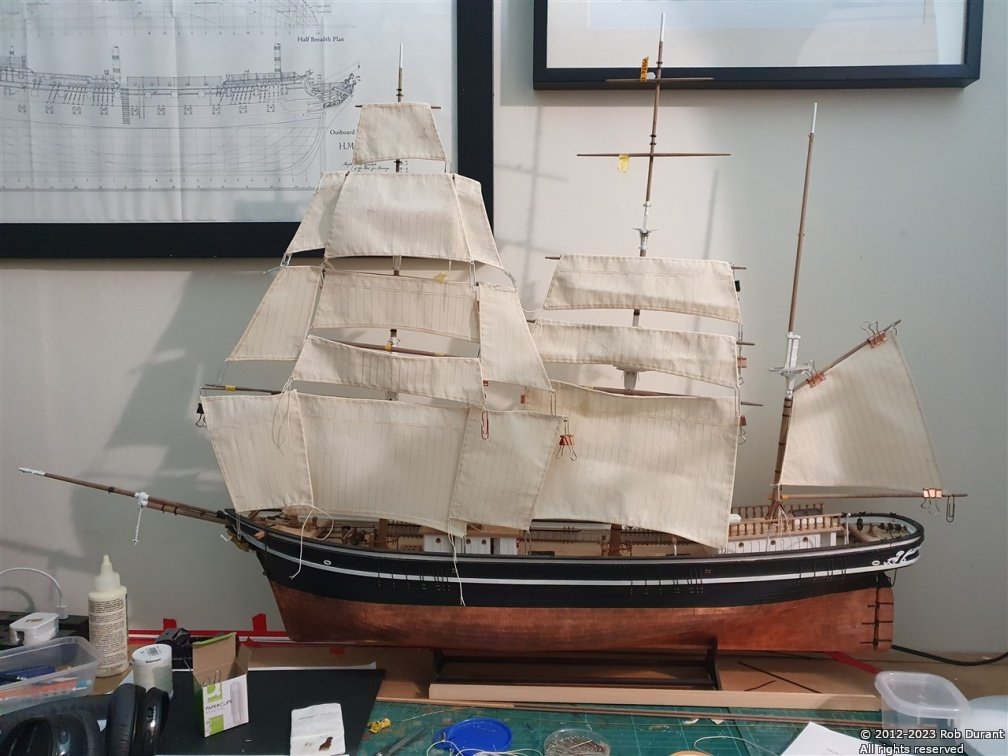
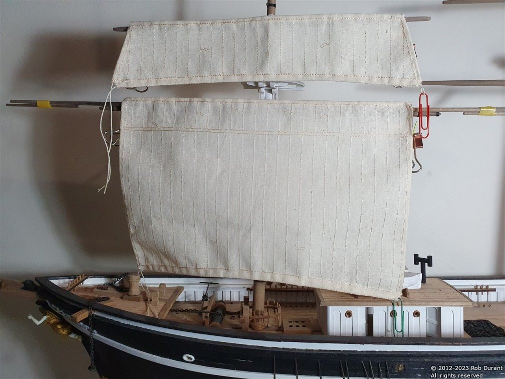
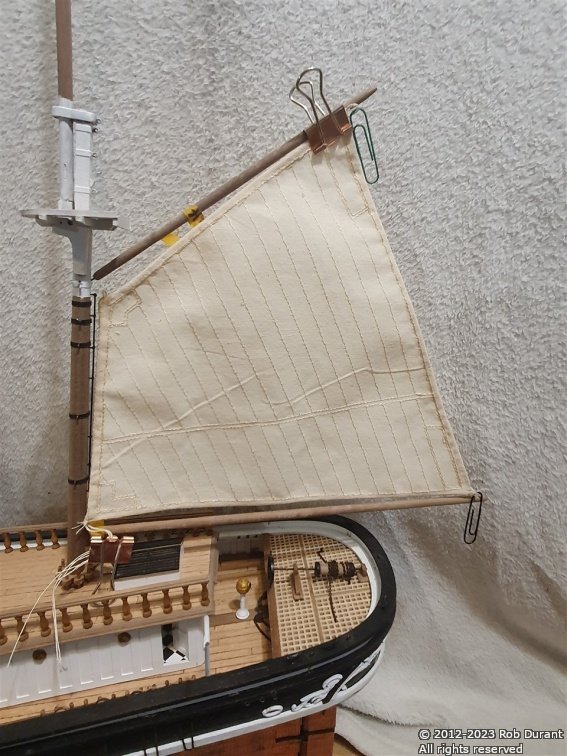
A few more sails... The fore mast is now full and I'm onto the main mast sails... (all just hung temporarily over the yards) I've also made a couple of the staysails, but those aren't in the photo. Thanks for the likes.
-
Really great work. Congratulations! The sea is very convincing, too. Thanks for showing us how you've gone about this build.
-
If you're using pva glue (or carpenter's glue) you may find it a good idea to weight these down flat until they're really dry. The moisture from the glue on the one side of the parts can cause them to warp and it's nigh on impossible to get the twist out of them again.
-
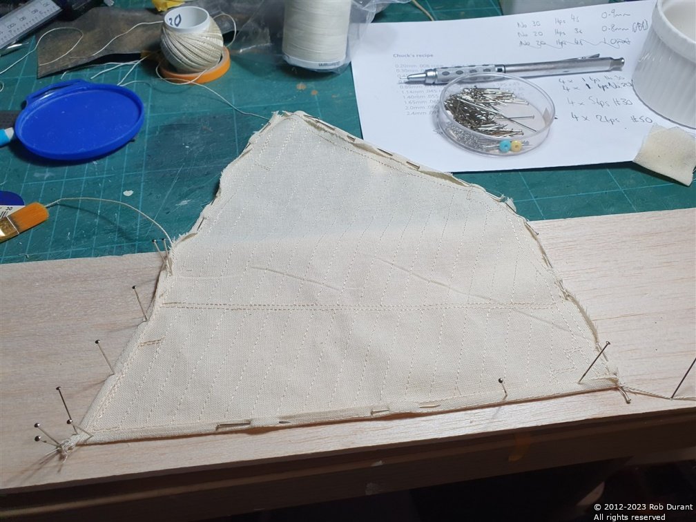
Thank you, Rob And a couple of studding sails... I've discovered that sewing sails is actually really really relaxing (except for when I'm stabbing myself with dress-making pins!)... I can strongly recommend this as an enjoyable part of making the model. The plans include complex instructions for hemming the corners - due to the relatively coarse nature of the sail cloth, I have found it to be far too apt to fray for this to be possible (there's nothing left to sew that close to the edge of the fabric). Once the hems are done it all becomes much more manageable. Others with more experience of this may have excellent suggestions as to how this can be avoided. But I'm pleased with the results I'm getting, and as always, though I may not be able to reproduce them exactly they plans themselves are works of art, which I shall enjoy long after I've finished this model. Care has to be taken with the studding sails (which are RH and LH), to ensure the hems are put on the back of the sail, and you don't end up with two RH or two LH! I've avoided this frustration so far... Check twice, sew once, is the order of the day Happy building, all. Rob
-
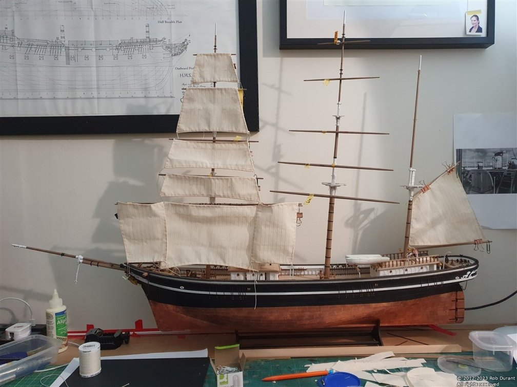
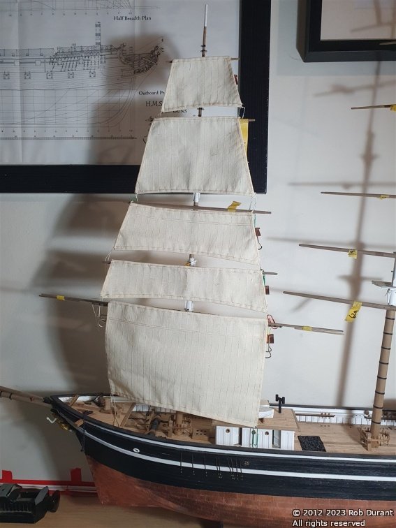
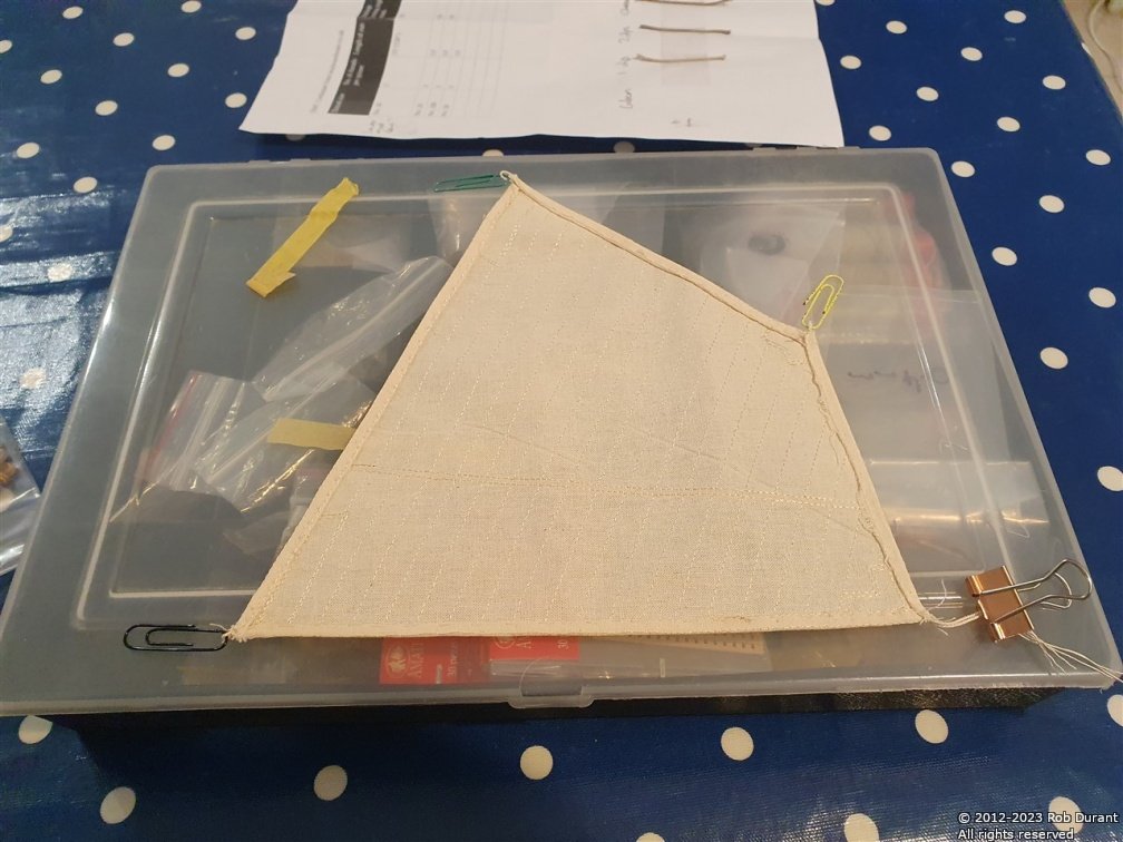
Just a very brief update - I've completed hemming the foremast course, lower and upper topsails, topgallant and royal... so here it is - the pyramid of sail... More soon Rob
-
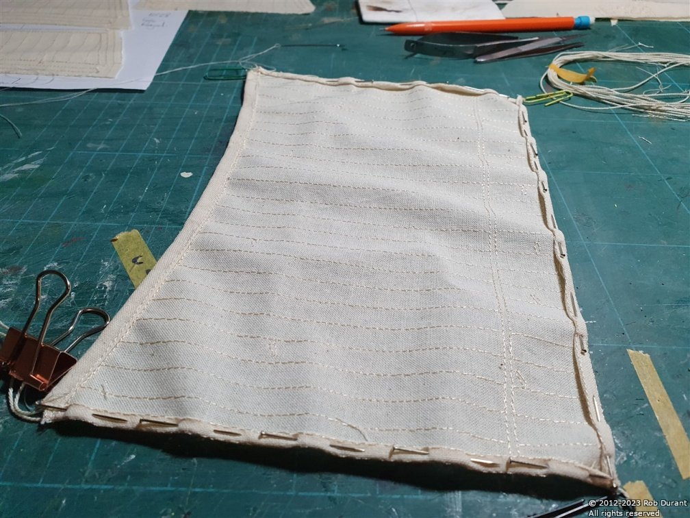
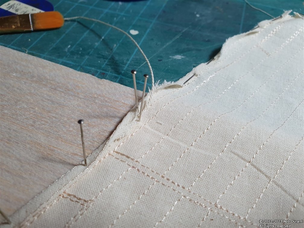
Thank you for the advice and the encouragement, Rob. I don't own a drill press, so it will just be a case of marking it out and being as accurate as I can with hand tools. I think part of the problem was that I was drilling the holes too small, and then in the process of trying to push in the eyelets, I was bending the wire. Practise should make better, if not perfect, and I'm not scared of a do-over. I've been doing some more work hemming the sails for the foremast... The paperclips stop the loops on the rope from disappearing into the hem until they're finally fixed. That should happen when I sew the bolt rope on to the edges of the sail.
-
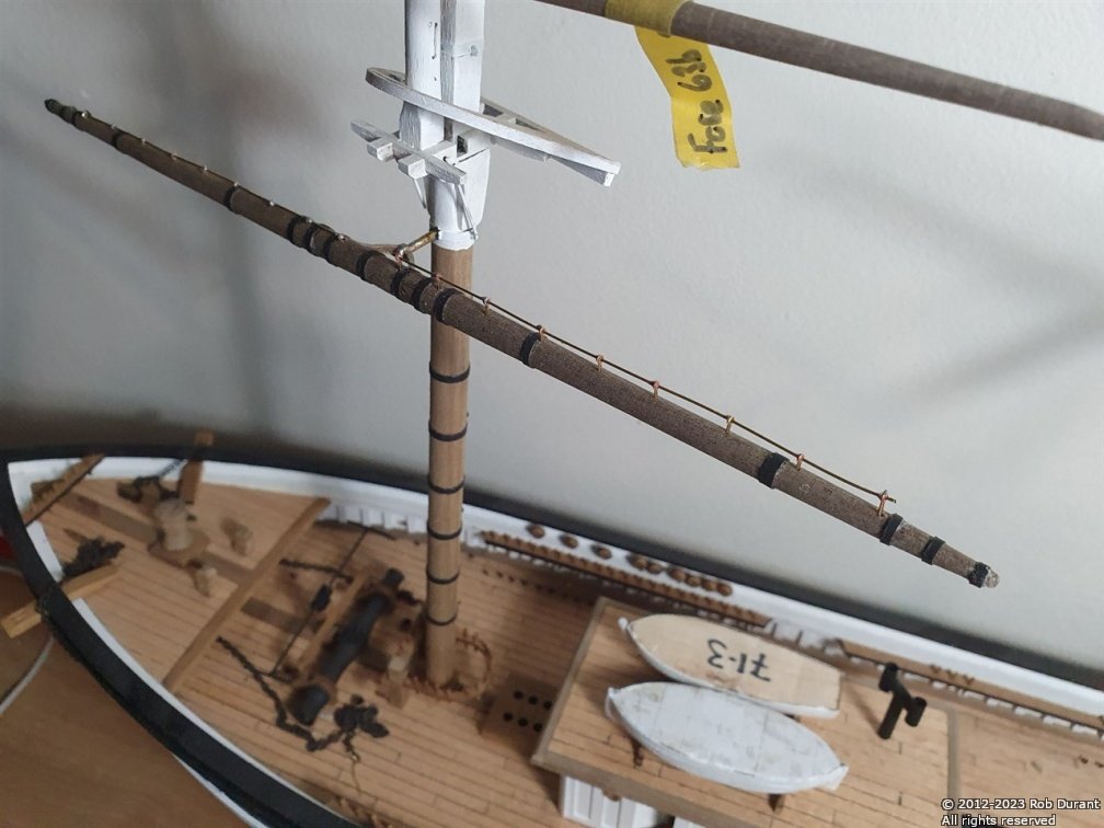
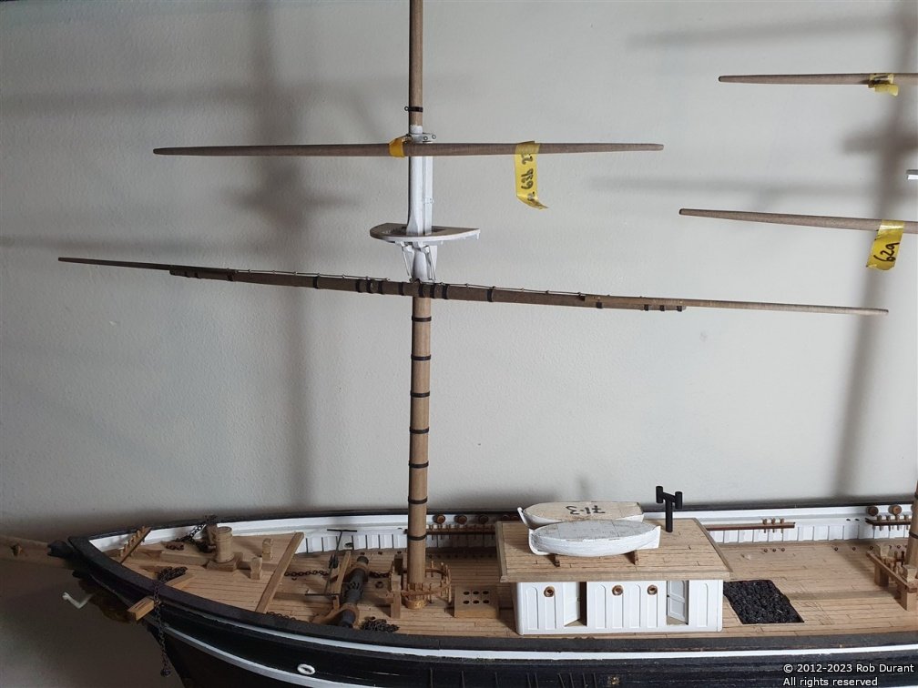
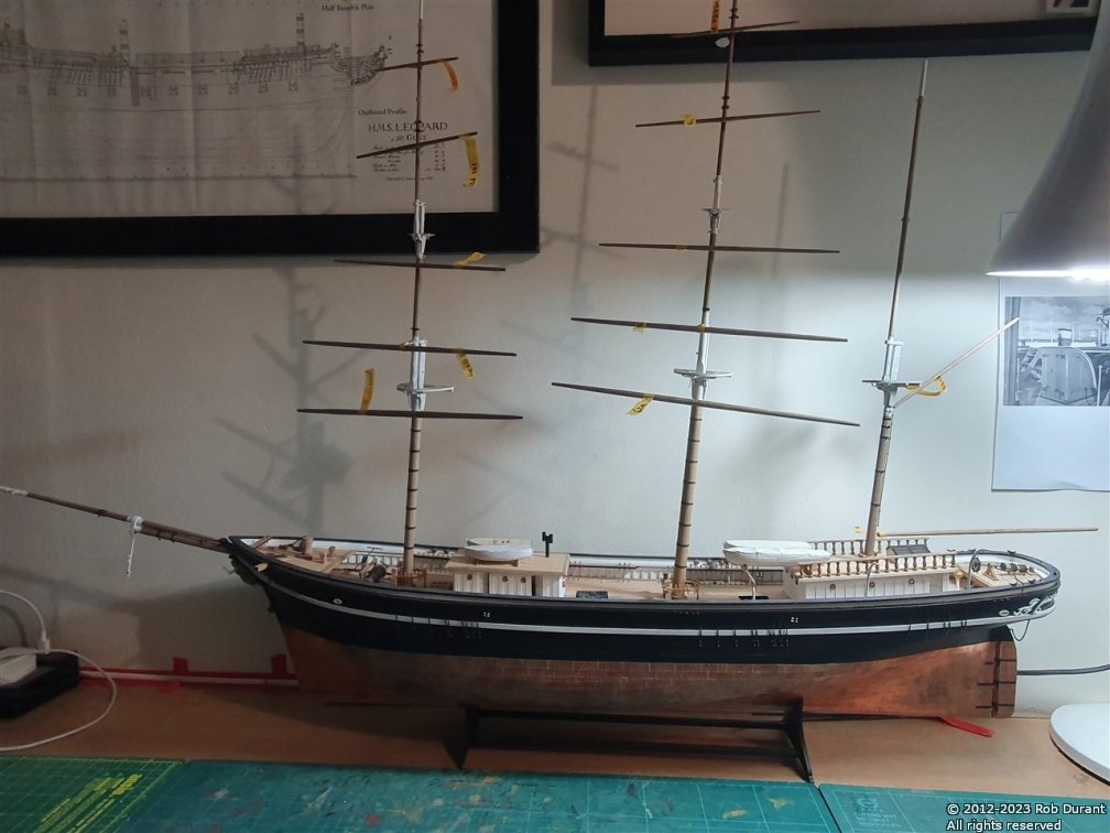
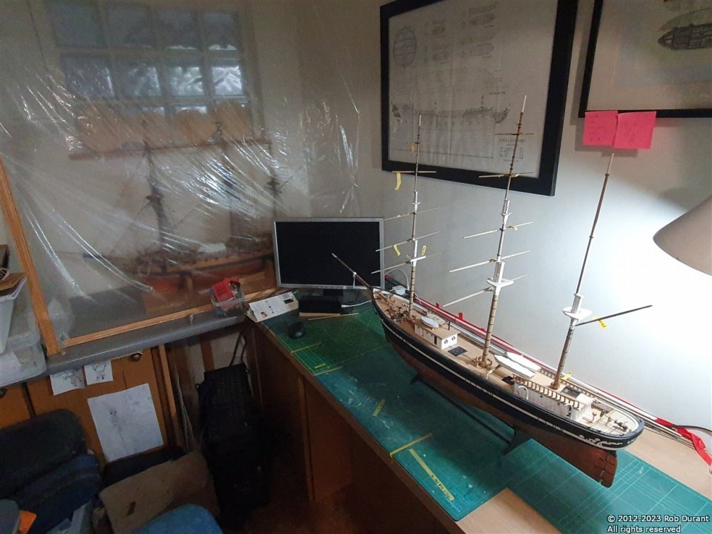
Thank you, all, for the likes and encouragement. It does spur me on Work has moved on to completing the yards. I've begun with the lowest yard on the foremast. I've added black cartridge paper banding, and had a first attempt at the rails that the sails are attached to. I'm not quite happy with these yet, but it's soldered so I can go back and have another go. I've also decided to build Stefano with stuns'ls deployed... it'll make the model a full 15cm wider than if the stunsl booms were retracted, but it'll also make her a very imposing sight indeed... so... I'll go for it, and worry about where I'll keep her later! The first photo is one of my cleared up boat desk with Ethalion in the background... With the masts rotated, she pushes to the back of the desk and that gives me room to work on whatever's going on that day. And a couple of photos of the progress on the foremast main yard. And with the stunsl booms attached temporarily... These are pinned in place, and then black cartridge paper will cover these attachments to look like the iron bands that would have held them in place. That's it for this evening. Happy building, all. Rob
-
Okay - time for another update. Version 1.10 - If you select the option to modify individual images as they are resized, you will now notice that there is an option to modify the saturation, hue and luminance for each image. This allows you to make them black and white for example, by reducing the saturation to the minimum. The functionality is described in the documentation, which can be found here: PictureResizer.Documentation.20221222.pdf And the app itself is on the website: https://www.durant.biz/pictureresizer/ As always, this is programmed in my spare time to try and be helpful, so I do all I can to make sure it will play nicely, but you do use it at your own risk. I've started playing with cropping, and hope that there might be the possibility of cropping images before they are resized someway down the line. I know it's possible, but I haven't managed to get it working reliably yet, hence I'm not sending it out into the wild Watch this space! Take care Rob
-
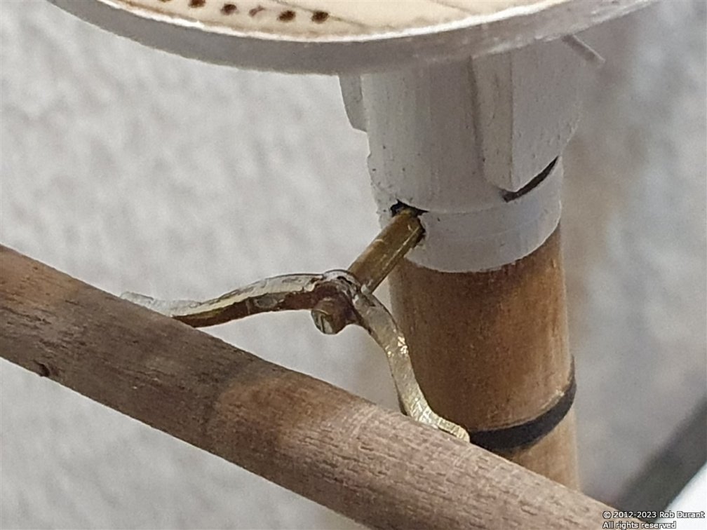
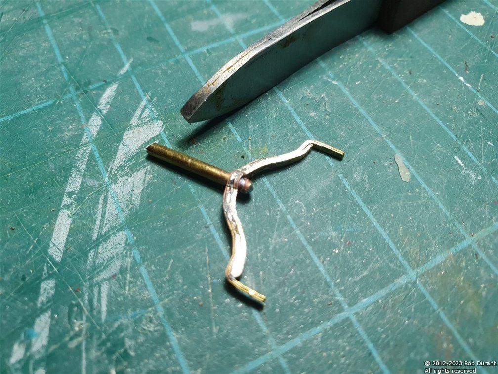
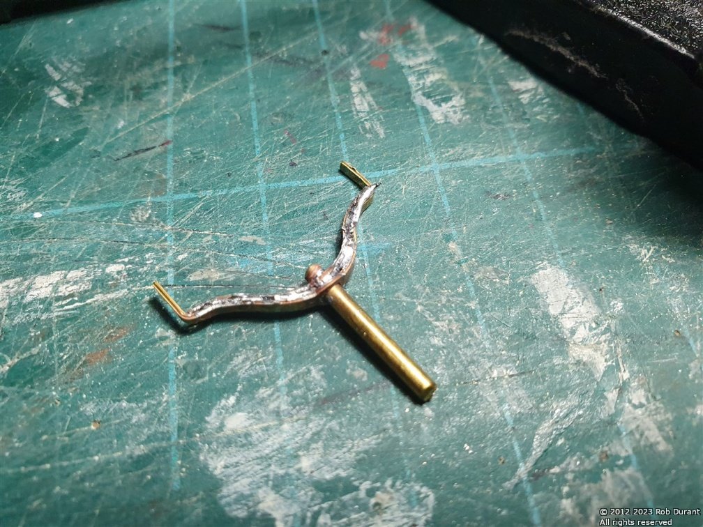
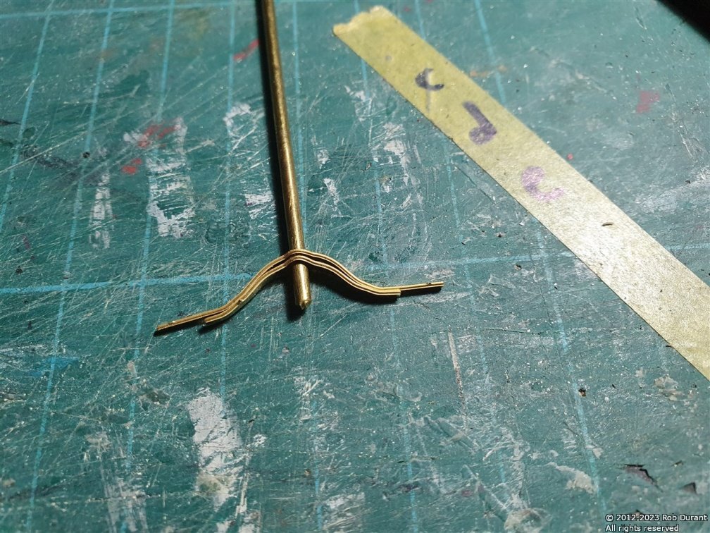
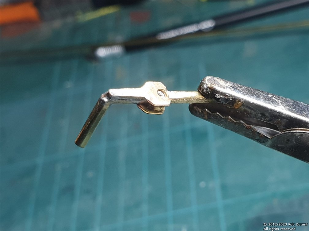
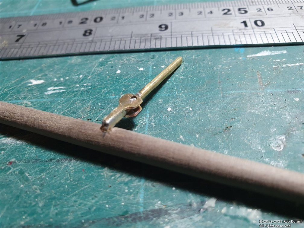
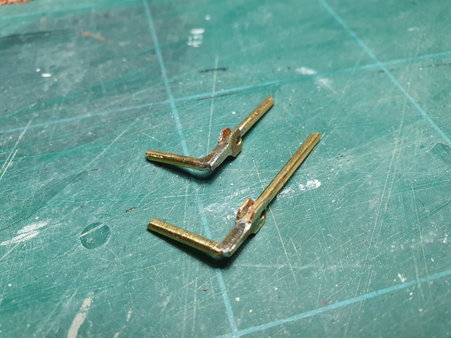
Thank you all for your likes, and for showing an interest. I've finished mounting the yards today. This involved making up the lower yard attachments, which are constructed from two layers of photoetch, with 2mm brass rod. I've simplified these somewhat to strengthen the attachment. Here are the original parts... Which are soldered together... And then tidied up with jewellers files... And here it is in place... The yards were now mounted to the yards... And I couldn't resist temporarily trying the part-completed sail in place, too... Now, I need to do a bit of tidying up Happy building and a happy new year to you all. Rob
-
Thank you Rob for your kind words. I use a small proxxon db250 lathe. It really does make the task simple. A tool I haven't regretted investing in.
-
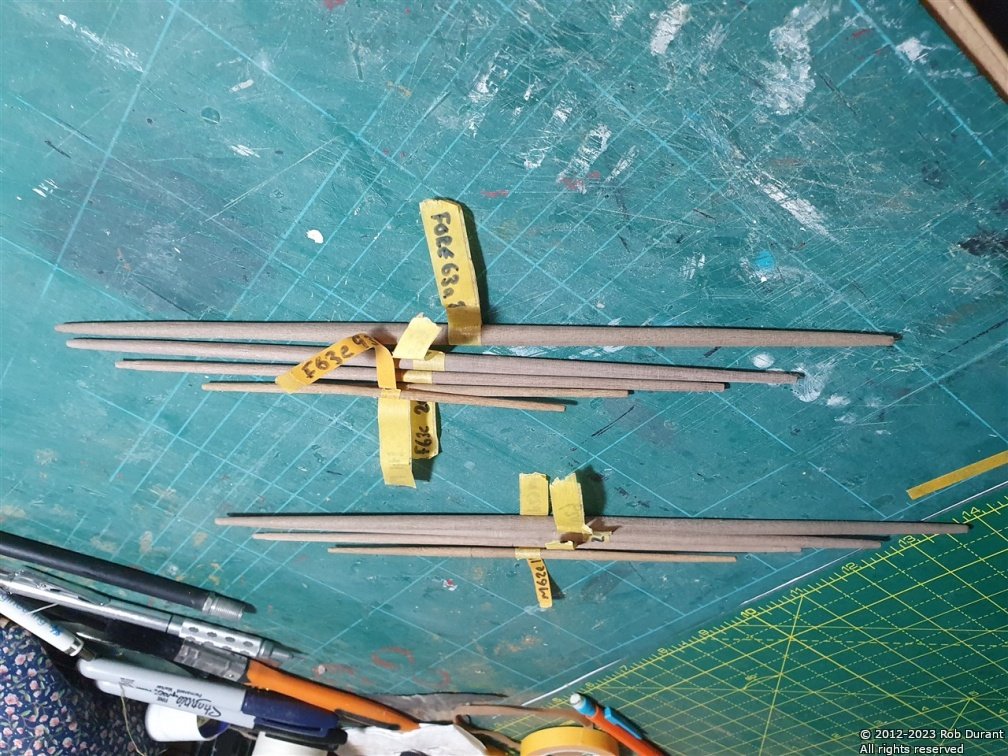
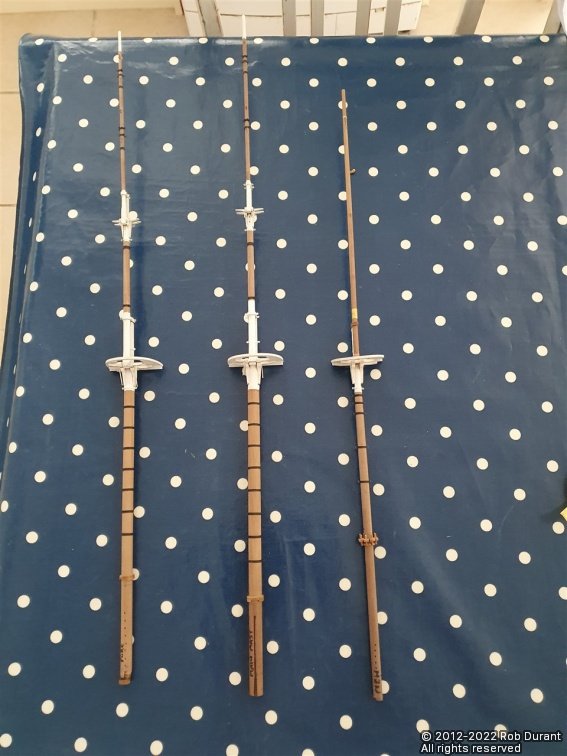
Hi all, I finished turning the yards yesterday. I also started work on the fittings that attach the yards to the mast. The top three yards on fore and main yards are laser cut, and the bottom two, photoetch. Unfortunately the photo etch does not leave the spare metal where it is folded and so I have not been able to form these as suggested in the plans. Instead I used brass rod and soldered parts of the photo etch. They will not be articulated, but they will be strong, which is a good thing.
-
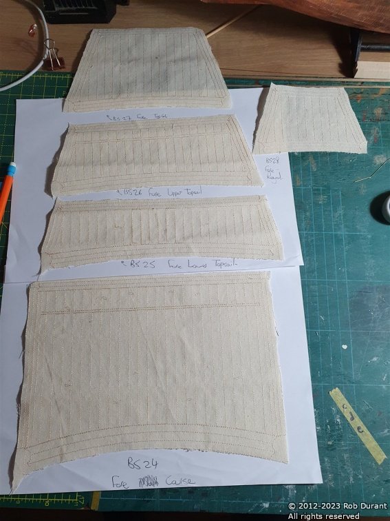
I've spent a while trying to work out how I could paint modelspan to represent sail cloth, but I seem not to have the knack, so having worked my way through a fair bit of acrylic paint and not come out with anything I was happy with my attention turned back to the sails contained in the kit. The sails have to be cut out and then double hemmed, with a 0.75mm rope (3strands, 1 threads per strand, #20 DMC Cordonnet) worked into the second fold. I've chosen not to include any glue (because it easily creates ugly watermarks) and to simply sew the hem. Sadly my sewing skills are not as good as I might hope, but I was pleased enough with how it turned out. There's plenty more to be done yet, but it's not a bad start. The next step should be to stitch a bolt rope round the periphery.
-
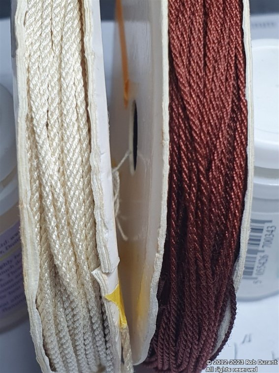
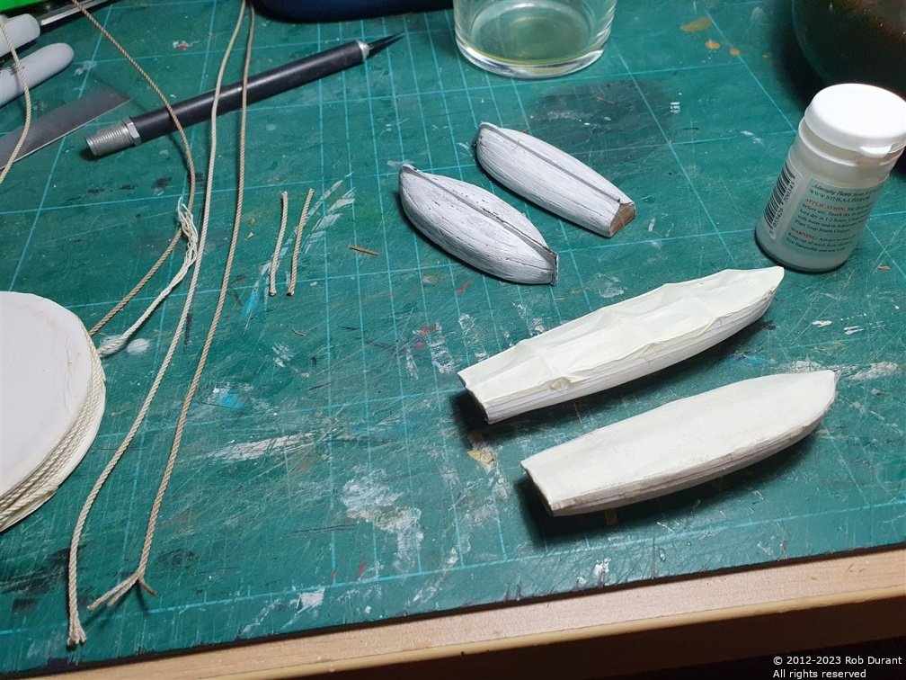
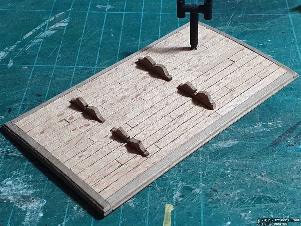
Happy Christmas everyone. I have a little progress to report. I've almost finished the ship's boats, and I've added the stands to the deck house roofs. I've also been working on rope-making. I've worked out the combinations I want to use for some of the standing rigging now, using the rope-rocket. Namely: Lower mast stays: 4 strands at 2 threads per strand of No. 50 DMC Cordonnet crochet thread (makes 1.1mm rope) This is then coloured using Rit Cocoa Brown dye (I tried using Colron wood dye, but it seemed to have very little effect on the rope) - approximately 1 tsp of dye for 500ml water, with a few drops of washing-up liquid. This is heated gently on the hob, and then the rope dipped in it. I tried simply dipping the rope in, but it tangles horribly. I've also tried drawing it through, but this is horribly messy. Finally, I tried making hanging the rope loosely coiled from brass wire - this allows me to dip it and draw it all out in one go. I've also been working out the best way to do the sails, but I'll post that as a separate entry.
-
Wow... this is impressive. My eyes wouldn't cope with 1:700 these days.. I remember trying not to breathe attaching a rear rotor blade to a lynx helicopter for a British type 42 destroyer in 1:700, but nothing approaching the results you are getting here. Very nice
-
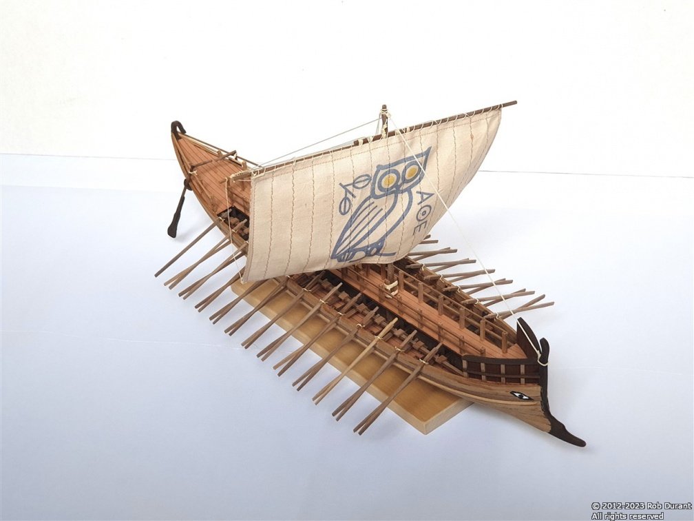
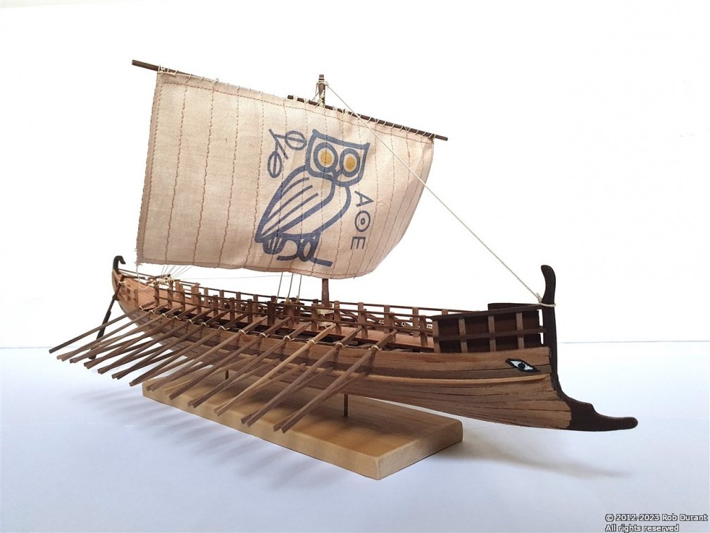
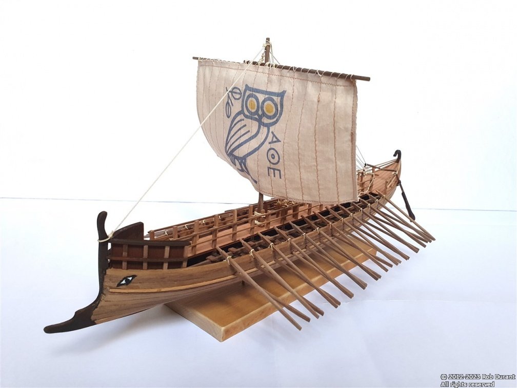
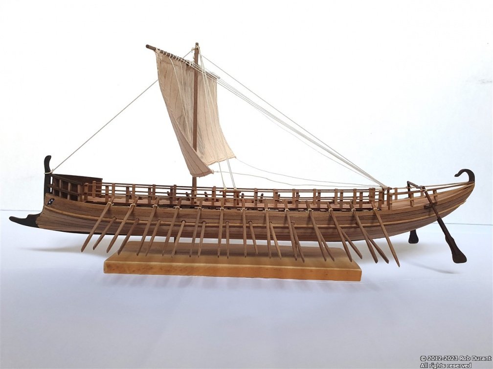
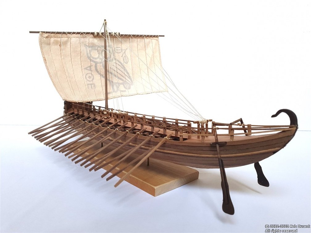
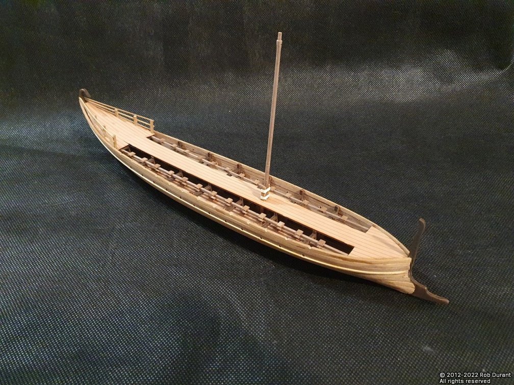
As promised, albeit slightly off-topic - here are a couple of photos of the Bireme I've just completed... I'm really pleased with the results. Not perfect, but pleasing, nonetheless, and not too bad for a first attempt at a rowed vessel. Happy building to you all Rob
-
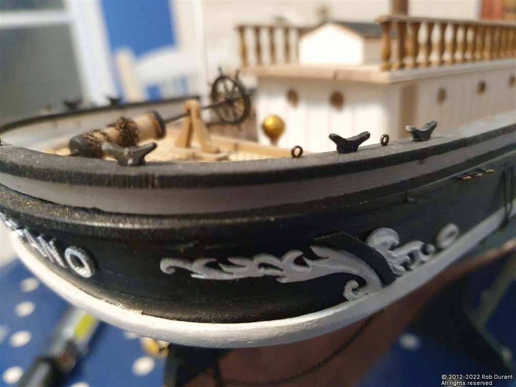
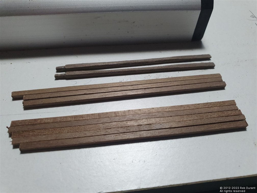
Well, life gets busy, and suddenly months have passed. I've finally finished the Greek Bireme, which I've named Ἀθηνα (Athena). It has the Owl sail, and will soon be setting sail for its new home. I haven't taken the final pictures yet, but I'll post a couple here when I do. Having finished the Bireme, I'm now able to pick up work on Stefano, which I'll admit I was somewhat daunted by. Today I've managed to get my head back into the things I was trying to accomplish. The cleats (part 70) are 2mm walnut, and I was concerned they would simply disintegrate or pull off the rail when they had rigging attached to them, so I've replaced them with some metal cleats I had left over from my Ethalion build. These have a 1mm rod on the bottom that provides for a stronger connection. I've also picked up the work on the lifeboats and adding the lifeboat stands to the forward deckhouse roof. Only a little progress, but it's good to be moving forward again. Happy building, to you all, and I hope you all have a wonderful Christmas! Rob
- 286 replies
-
- 10
-
-
Love those props... looking really smart, now.
-
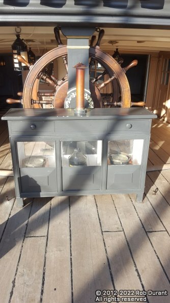
David's looks remarkably similar to the one onboard HMS Victory in Portsmouth. Perhaps this was the source? Very nice work, David. Rob
-
Looks like a great start. Hope you don't mind if I follow along.
-
uploading pictures
robdurant replied to David56's topic in Using the MSW forum - **NO MODELING CONTENT IN THIS SUB-FORUM**
If you use a quality around 85-90 you shouldn't have any issues at that resolution of 1200x1600 pixels, and the image should be good quality and not showing any noticeable compression artefacts. -
Thank you Bob. A simple build, but a very enjoyable one.
-
Right, an update is long overdue. Not a huge amount to show on Stefano, as I'm working to finish off the Greek Bireme I'm building for my wife... I've finished putting the eyelets onto the masts. There's still some detailing to be done, but they're getting there. In Greek-Bireme-land, things are moving ahead, too... I'm making oars now... one by one, by one, by one.... More soon, hopefully. Happy building to you all. Rob
-
Hi Valeriy, I echo all of the high praise being given for this superb model. I wondered whether you used some form of stamp to create those cross-shaped pieces for the flywheels? Or are they cut out by hand... regardless, the accuracy and consistency of your work is quite astounding. All the very best wishes for you. Rob


