HOLIDAY DONATION DRIVE - SUPPORT MSW - DO YOUR PART TO KEEP THIS GREAT FORUM GOING! (Only 13 donations so far - C'mon guys!)
×


robdurant
-
Posts
842 -
Joined
-
Last visited
Content Type
Profiles
Forums
Gallery
Events
Everything posted by robdurant
-
 Hi Shipman. My desire in writing this software was primarily that it hard-coded the information that sets the rotation on website pages...This rotation information causes a lot of confusion to users who see a photo the right way up on their cameras but then it displays the wrong way online. It may well be that the software you have pointed to does the same, but I had struggled to find something that did that reliably for free Glad you found an app that works well for you. Rob
 -
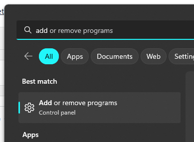
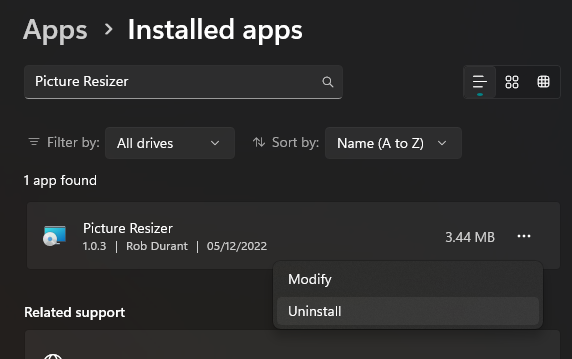
Hi, If you click the windows button, and type "add remove program" and select "Add or remove programs" Now , you can search for the Picture Resizer application, select the three dots on the right hand side and uninstall it. Once that is complete you can install the new version downloaded from the website. Hope that helps. Rob
-
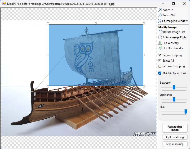
Version 1.13.0 now available on https://www.durant.biz/pictureresizer now supports cropping (with the option to maintain the aspect ratio of the image) on a per image basis as you resize your photos. Simply select "begin cropping" or click and drag to select a region of the image, then resize it until you're happy with the size. Selecting the "maintain aspect ratio" checkbox will mean that each time you resize the selection it will keep the width to height ratio the same as that of the original image (i.e. 16:9, 4:3, etc...) Then when you resize the image, it will crop the image to the rectangle. Hope it's helpful Happy resizing! Rob
-
Thank you Ian. You're very kind. Yes, I made the ropes using the Syren rope rocket and DMC cordonnet crochet thread, dyed with Rit fabric dye. It is wonderfully rewarding rigging with your own rope, and there's no anxiety about running out
-
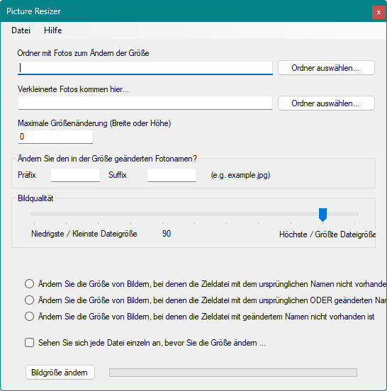
I'm conscious that many of our wonderful family here on ModelShipWorld.com are not native English speakers. My little offering to brighten your day is Version 1.12.0 of Picture Resizer (available at https://www.durant.biz/pictureresizer/ ) which now supports languages natively for the main application window (I'll add support for the other windows soon). All you need do is install the application and it will show the application in the language your computer uses (It currently supports French, German, Dutch and English) if it can't find your language, it will drop back to English) Languages are not my area of expertise, so "Calling all linguists"... If you speak German, French or another language, and you're reasonably au-fait with computer, and you would like this application to support your mother-tongue / preferred language natively, please could you translate the following, and I'll add this support into the application... The English terms at the moment are as follows, and the French, German and Dutch attempts are below (with big apologies in advance for what are a mix of guesswork and google translate... please help me make these better!) English originals Resize Images Image Quality Highest / Largest filesize Resized photos go here... Folder with photos to resize Maximum resized dimension (width or height) About... Exit File Help Load settings... Save settings... Modify the resized photo name? View each file individually before resizing... Prefix Resize all images in source folder Resize images where destination file with modified name does not exist Resize images where destination file with original OR modified name does not exist Resize images where destination file with original name does not exist Select Folder... Lowest / Smallest filesize Suffix French: Redimensionner les images Qualité d'image Taille de fichier la plus élevée/la plus grande Les photos redimensionnées vont ici... Dossier avec photos à redimensionner Dimension redimensionnée maximale (largeur ou hauteur) À propos Quitter Fichier Aider Charger les paramètres... Enregistrer les paramètres... Modifier le nom de la photo redimensionnée ? Affichez chaque fichier individuellement avant de redimensionner... Préfixe Redimensionner toutes les images dans le dossier source Redimensionner les images où le fichier de destination avec le nom modifié n'existe pas Redimensionner les images où le fichier de destination avec le nom d'origine OU modifié n'existe pas Redimensionner les images où le fichier de destination avec le nom d'origine n'existe pas Sélectionner le dossier... Taille de fichier la plus basse / la plus petite Suffixe German: Bildgröße ändern Bildqualität Höchste / Größte Dateigröße Verkleinerte Fotos kommen hier... Ordner mit Fotos zum Ändern der Größe Maximale Größenänderung (Breite oder Höhe) Über Photo Resizer... Picture Resizer beenden Datei Hilfe Einstellungen laden... Einstellungen speichern... Ändern Sie den in der Größe geänderten Fotonamen? Sehen Sie sich jede Datei einzeln an, bevor Sie die Größe ändern ... Präfix Größe aller Bilder im Quellordner ändern Ändern Sie die Größe von Bildern, bei denen die Zieldatei mit geändertem Namen nicht vorhanden ist Ändern Sie die Größe von Bildern, bei denen die Zieldatei mit dem ursprünglichen ODER geänderten Namen nicht existiert Ändern Sie die Größe von Bildern, bei denen die Zieldatei mit dem ursprünglichen Namen nicht vorhanden ist Ordner auswählen... Niedrigste / Kleinste Dateigröße Suffix And Dutch Formaat van afbeeldingen wijzigen Beeldkwaliteit Hoogste / grootste bestandsgrootte Verkleinde foto's komen hier... Map met foto's om het formaat te wijzigen Maximale afmeting gewijzigd (breedte of hoogte) Over... Uitgang Bestand Hulp Instellingen laden... Instellingen opslaan... De gewijzigde fotonaam wijzigen? Bekijk elk bestand afzonderlijk voordat u het formaat wijzigt... Voorvoegsel Wijzig het formaat van alle afbeeldingen in de bronmap Wijzig het formaat van afbeeldingen waar het bestemmingsbestand met gewijzigde naam niet bestaat Wijzig het formaat van afbeeldingen waar het bestemmingsbestand met de originele OF gewijzigde naam niet bestaat Wijzig het formaat van afbeeldingen waar het bestemmingsbestand met de oorspronkelijke naam niet bestaat Selecteer map... Laagste / kleinste bestandsgrootte Achtervoegsel Thank you for all your help This is truly the benefit of a global community! Hope it's of help. Rob
-
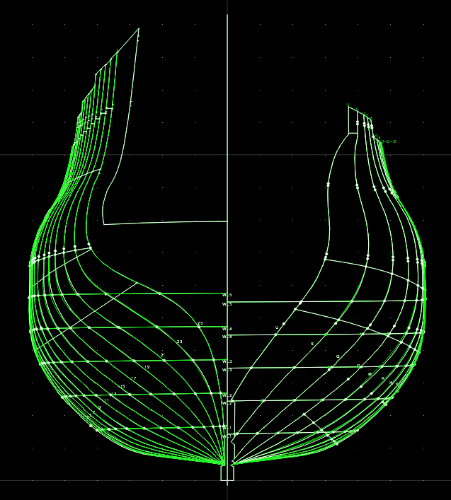
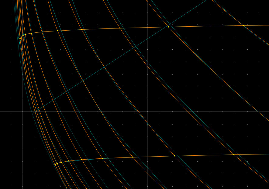
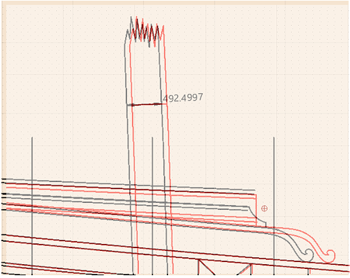
Thanks Dusan, I've been working on the table of offsets. 1. I traced the stations, giving the following table: (note negative values are because I've maintained the right of centre and left of centre frames so I can easily do a visual check of the output with a line graph.) TRACED FROM PLAN Distance from centre (mm, 1:1) Station WL0 WL1 WL2 WL3 WL4 WL5 U 735 1476 2268 S 303 1120 2056 3019 3825 Q 921 2068 3202 4162 4820 O 1560 2929 4102 4976 5438 M 2153 3618 4747 5490 5805 K 2775 4218 5207 5784 5972 H 3247 4617 5485 5923 6025 F 3604 4856 5635 5999 6066 D 3787 4975 5688 6014 6066 B 3908 5019 5712 6015 6066 Ø 3990 5065 5737 6015 6066 Ø (bow) -4001 -5064 -5740 -6031 -6069 1 -3940 -5016 -5724 -6032 -6069 3 -3848 -4949 -5675 -6022 -6059 5 -3631 -4811 -5602 -5992 -6049 7 -3428 -4640 -5486 -5934 -6029 9 -3088 -4394 -5324 -5850 -5976 11 -2541 -4027 -5078 -5692 -5912 13 -2029 -3581 -4754 -5507 -5795 15 -1505 -2997 -4272 -5192 -5591 17 -1062 -2348 -3706 -4805 -5364 19 -718 -1636 -2855 -4236 -5062 21 -434 -981 -1936 -3344 -4582 23 -229 -496 -1050 -2163 -3725 25 -111 -210 -416 -879 -2079 AP The second task was to cross-check these against the half-breadth plan, which gave the following offsets: Distance from centre (updated by half-breadth) (mm, 1:1) Station WL0 WL1 WL2 WL3 WL4 WL5 U 732 1490 2343 S 267 1052 2027 2925 3830 Q 910 2025 3120 4090 4803 O 1535 2878 4001 4922 5435 M 2131 3608 4679 5446 5788 K 2694 4186 5161 5763 5975 H 93 3181 4575 5454 5922 6055 F 960 3563 4826 5620 5983 6080 D 1453 3784 4968 5696 6005 6084 B 1717 3896 5046 5731 6022 6080 (B) 1824 3938 5075 5744 6030 6076 Ø 1845 3930 5062 5741 6024 6048 Ø (bow) -1844 -3923 -5054 -5739 -6020 -6048 1 -1794 -3868 -4997 -5724 -6003 -6045 3 -1619 -3770 -4904 -5687 -5992 -6038 5 -1342 -3639 -4803 -5630 -5978 -6033 7 -854 -3411 -4641 -5526 -5931 -6024 9 -111 -3055 -4389 -5360 -5845 -5996 11 -2571 -4028 -5118 -5720 -5920 13 -2031 -3562 -4782 -5528 -5795 15 -1492 -2972 -4308 -5220 -5630 17 -1062 -2334 -3704 -4831 -5421 19 -707 -1638 -2883 -4232 -5121 21 -434 -991 -1930 -3307 -4624 23 -235 -509 -1093 -2134 -3670 25 -106 -211 -429 -885 -2042 AP Finally, I copied these back over the plans, and made a few modifications to the U and S stations at WL5 and WL4 so that the stations flowed smoothly. The following changes were made: U, WL5 = 2190 S, WL4 = 3018, WL5 = 3788 The following image shows the original lines traced off the plans in white, and the updated lines taken from the half-breadth in green. As can be seen, the differences are fairly negligible, except at the extreme breadth, where they become a little more significant. The difference amounts to a maximum of 7.7 centimetres at 1:1 scale, so nothing too dramatic. This image shows some of the differences more closely - cyan is the plan lines, and orange the updated lines from the half-breadth. The next step is to begin working out framing distances, and lofting the frames using the curves these stations produce... Anyway - that's enough from me for now. Happy building, all.
-
Looking at those pictures it really is shocking how close the lower gunports were to the waterline. The idea of these ships heeling under sail is scary. Thank you for sharing this research and build with us all. Simply fascinating.
- 2,696 replies
-
- 4
-

-
- heller
- soleil royal
- (and 9 more)
-
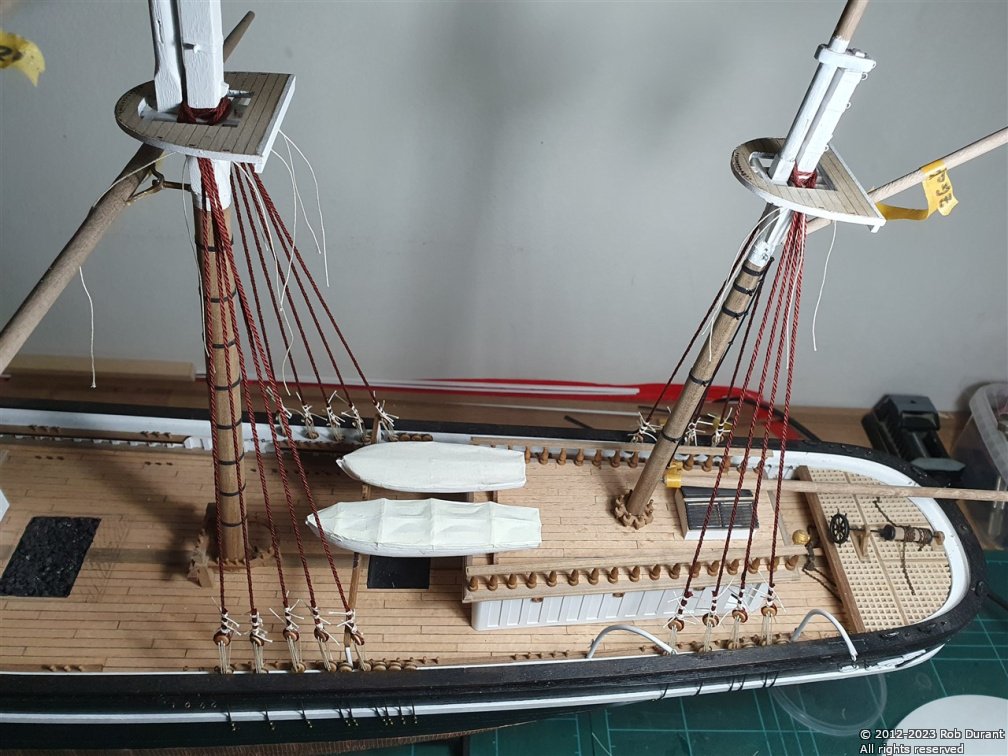
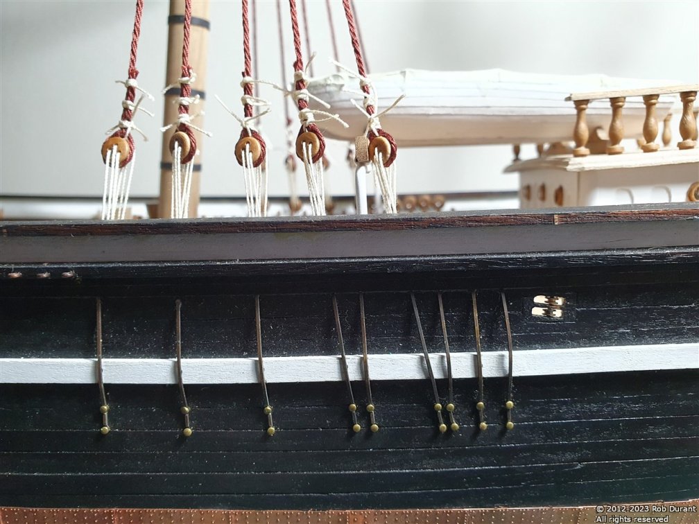
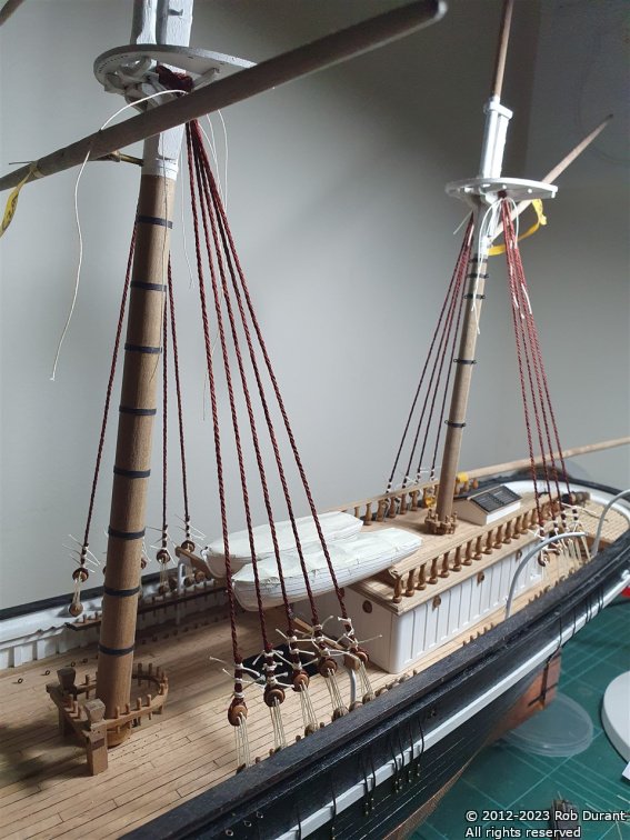
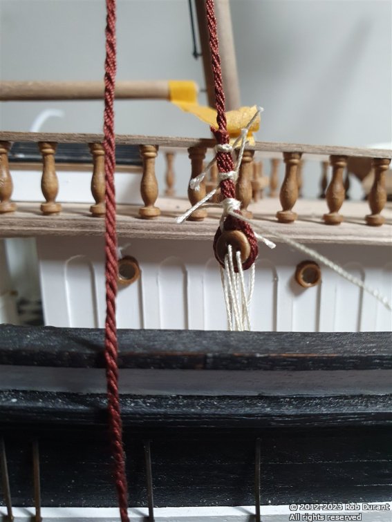
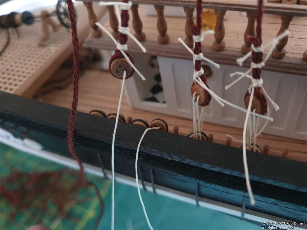
Okay - so today I added the bolt rope to another sail - no need to add pictures for that. It's another stay sail, so they would look pretty much identical to the previous pictures I've posted. Then, as a change of scenery, I began adding the mizzen shrouds. These are using (as a note to self as much as anything) 4 strand, 2x threads per strand, from #50 DMC Cordonnet thread, dyed in Rit Cocoa brown die. The captain's clearly a showy so and so, so he's used contrasting natural #20 DMC cordonnet thread for the lanyards. The lanyards are something of a challenge. I've added two starboard pairs and one port pair so far (alternating sides, beginning to starboard), and because the dead-eyes are inside the railing, and the lanyard needs to pass through the railing from the outside on the lower deadeye, it took me lots of fiddling with tweezers, super-glue strengthened end of the lanyard and summoning of patience, before I realised that it was possibly simply to bend the deadeye in towards the centreline of the deck to rig it, and then bend it back out again. This is by far the easiest method I've found, and it's made the task achievable (still fiddly, but possible). I'm not sure whether leaving the deadeyes detached until this point would have helped matters, as I haven't tried that approach, but certainly one for builders of this model to watch out for. Here are some photos of progress so far. I haven't put watered down Aliphatic resin (carpenter's glue) on these yet, so the ends are left long intentionally. I'll do the whole lot in one go, once I'd happy they're all a good length. One deadeye is rigged off the ship (I have a little template to keep the distances consistent), then the shroud is wrapped round the mast, through the crosstrees and top, and brought back down to have the other deadeye rigged. Before I rig the second deadeye, I put on the first lanyard, so that I can gauge where the second deadeye should go. Thank you to everyone for the likes and encouragement.
- 286 replies
-
- 10
-
-
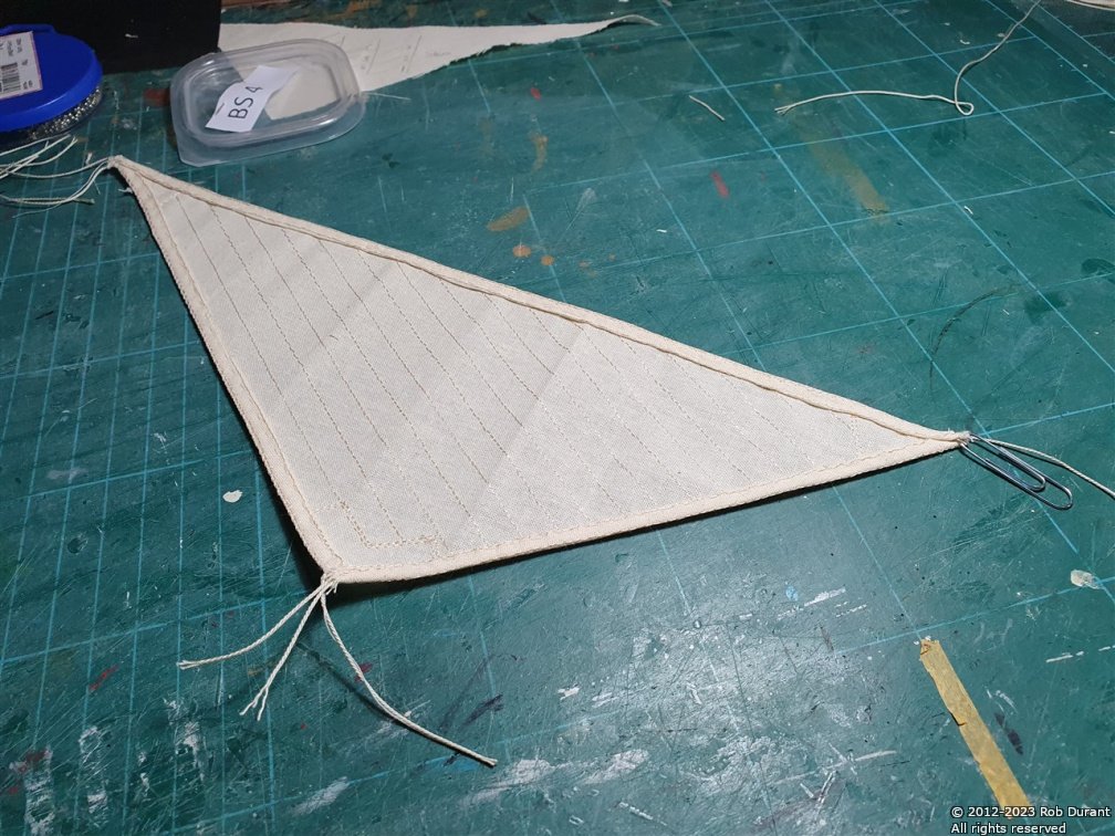
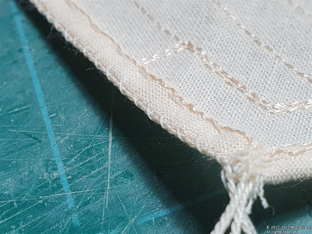
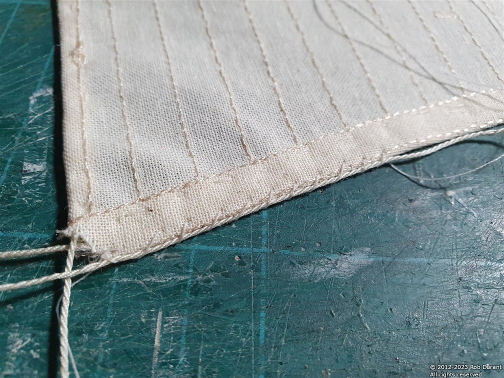
Thank you for the likes. I haven't stopped working on this, but it takes me a good couple of hours to put the bolt rope on each sail, so here is sail BS 4 getting bolt rope... COnsidering I haven't done a lot of sewing before, I'm pretty pleased with how it's coming out.
- 286 replies
-
- 11
-
-
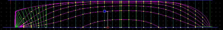
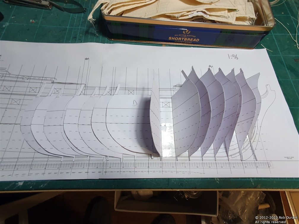
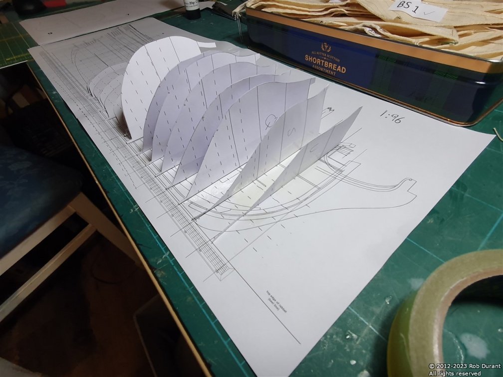
I couldn't resist seeing the model so far jump off the drawing board into real life, so I've started to make a basic paper half-hull mockup at 1:96 scale to get a sense of the lines. At the moment there's no lateral support for the frames, so they're all over the place, but an interesting exercise nonetheless, and adding the poop / quarterdeck / upper gun deck will help matters no end. The deck locations are marked with solid lines and waterlines are marked with dashed lines. This half-hull should help me work out how to go about realising the internal structure. Progress so far...
- 55 replies
-
- 12
-
-
Thank you Druxey. I'm using QCAD Pro (https://qcad.org) - I used a mac and linux for a good while, and this program is robust and works beautifully on each, but also on Windows which I used now. It has a free version which did the vast majority of what I wanted, but I was so pleased with it, I thought it worth supporting the developers. It can generate dxf files which import into blender, so there's no great problem if you want to take the work and use it for 3D work, too.
-
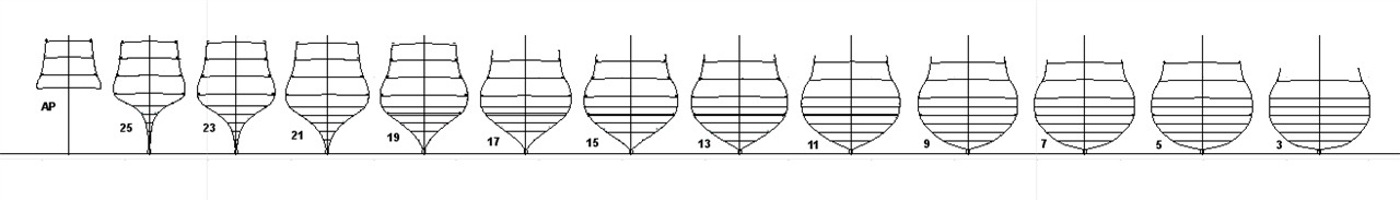
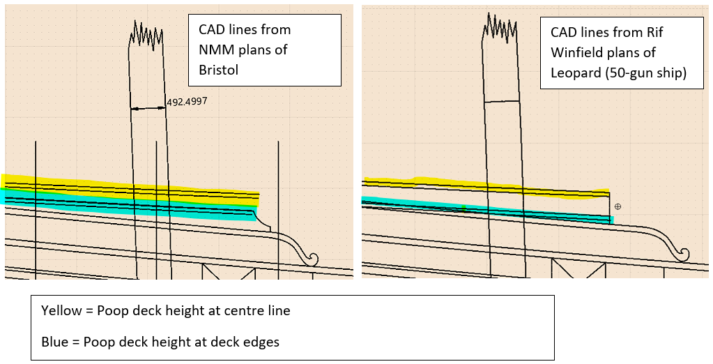
I spent a few hours working on the station lines yesterday - these are a first draft, but they contain the waterlines and upper and lower deck limits, which should help me double check them against the half-breadth. One interesting point was that there is an vertical extension to the bulwark at the forward end of the poop deck which allows the height between quarter deck and poop deck to be sufficient to accommodate the ship's wheel without having extreme camber on the poop deck. This extension doesn't show up on the Winfield Leopard 50-gun ship, Leopard plans. (My CAD from RMG plans on left, Winfield on right) The same images are shown below super-imposed: red is the sketch from Winfield, and black, from the Bristol NMM plan. Here, we notice that either the gunport location was slightly different (a matter of different framing?), or the Mizzen mast was moved between Leopard and Bristol, by a few inches (the more likely, I would think.) Nevertheless, the difference in height for the poop decks (between the beams) would have felt pretty significant if you were on the helm all day. 1.86m for Leopard at the centre line, and 1.92m for Bristol, or 6' 1" and 6' 3" in old money. Being 6' 2", I think I would have preferred Bristol! I also reconciled the mid-point stations for the aft stations (l.h.s of the plans) and the forward stations (r.h.s of the plans), and was concerned that they were miles out - until I realised that I was very zoomed in, and it worked out as a difference of 1.3cm on the full size ship - or 0.2mm on the model. I think I can live with that - a brush of sandpaper, or swipe of the scraper should reconcile the difference!
-
If you upload images to the "drag files here to attach" section of the post box (rather than dragging them straight into the text, and then you don't actually insert them anywhere in the post text, they will be added to the end of the post. In your post it looks as though you uploaded 13 photos, but only added some of them into the text - perhaps you deleted the others from the text - and so it added them automatically at the end of the post. To avoid this, you need to manually remove the images you have uploaded but aren't using from the "drag files here to attach" bit at the bottom before you click "submit reply". With that said, I enjoyed seeing the extra photos, so thank you for including them Rob
-
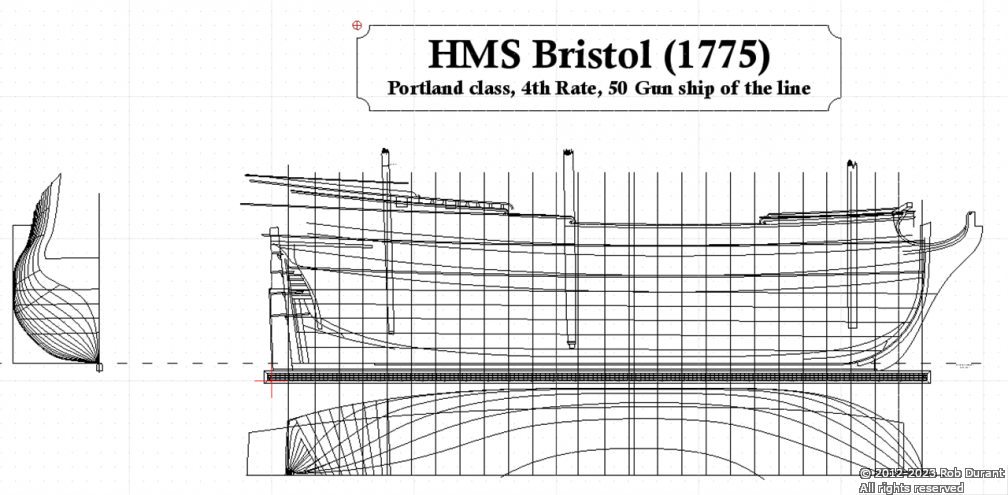
Some progress to show. I've started getting the plans into CAD ready to begin designing the skeleton of the model. A long way to go, but it's good to make a start. The actual plans are colorised, with different parts on different layers so I can separate them easily. Near the stern on the half-breadth plan some of the waterlines divide into two lines as they approach the rabbet. I've never noticed that on plans before, so if anyone knows what that represents I'd be interested to know. More soon Rob
-
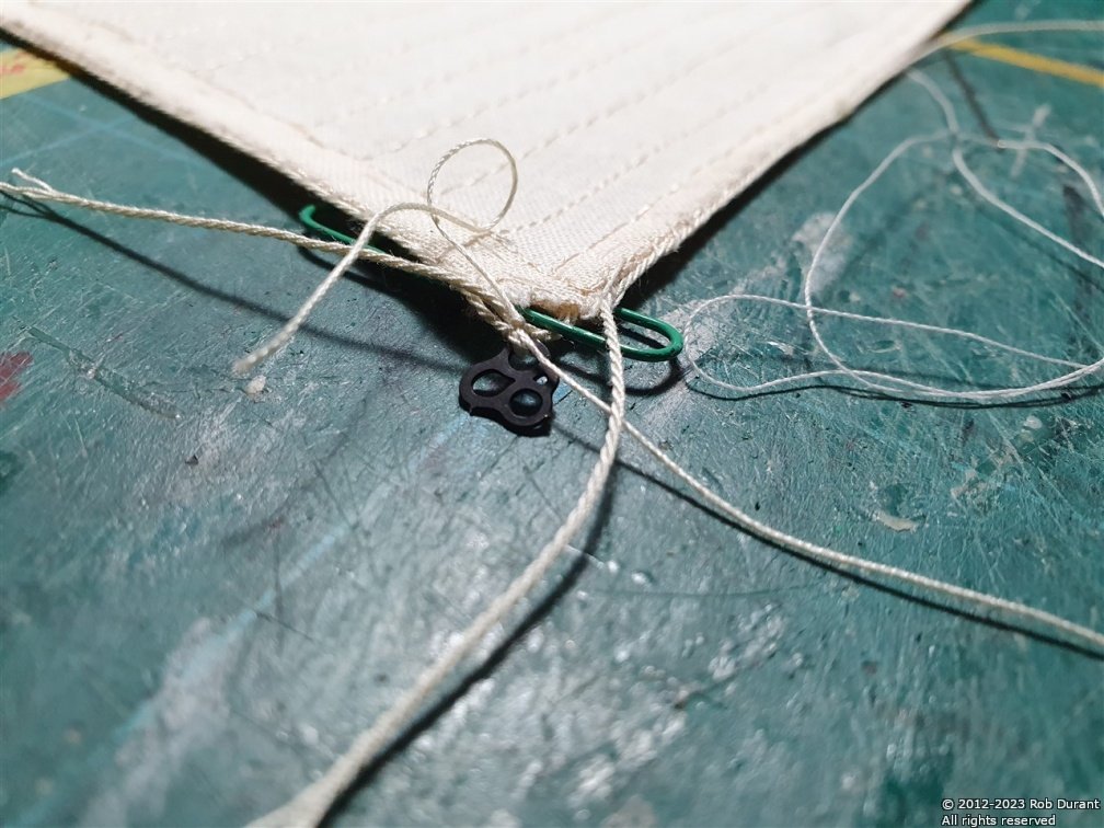
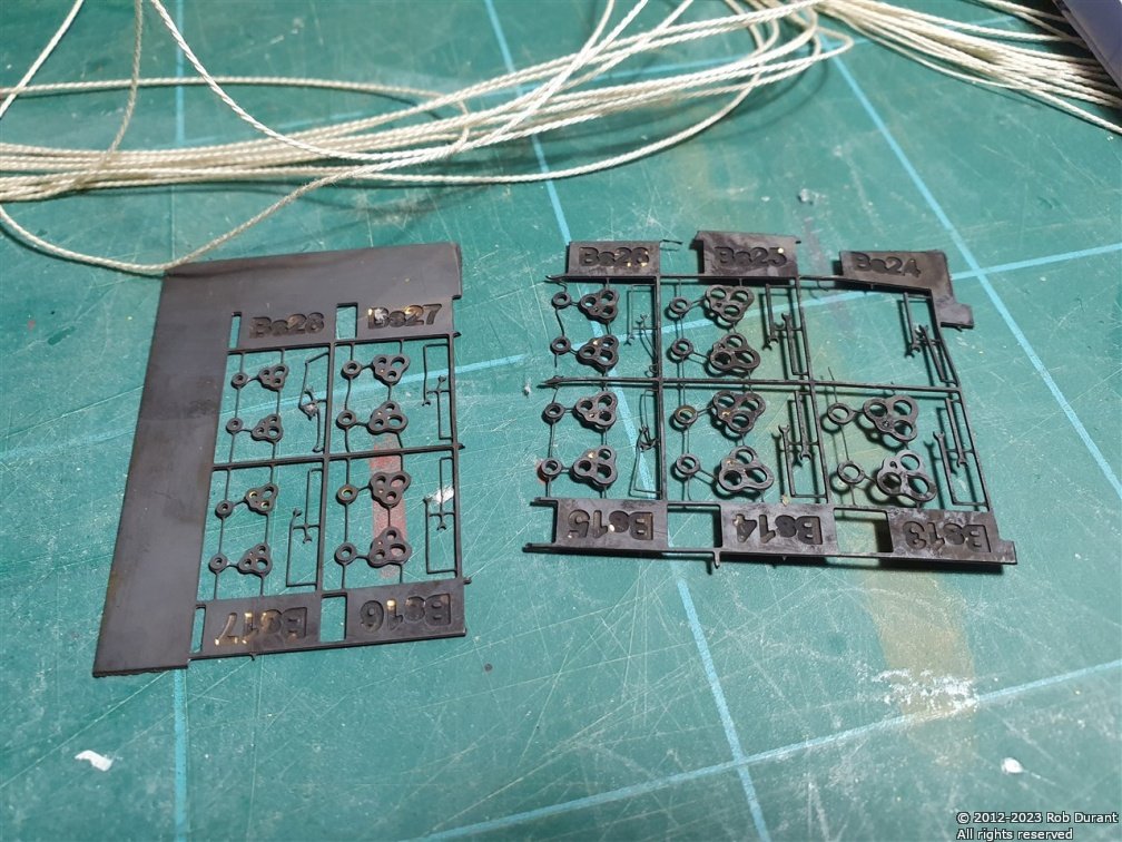
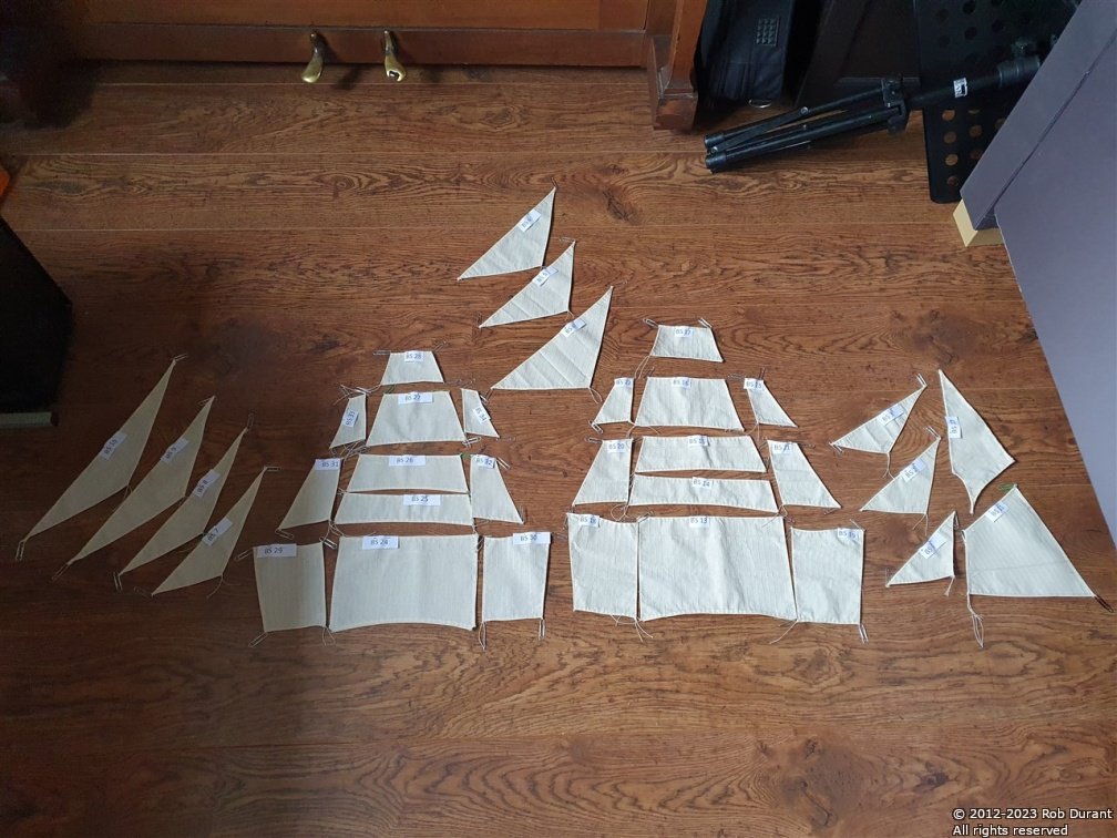
Hi all, I've finished hemming the sails, and now it's onto bolt ropes. For this, I made some thinner rope (3 threads per strand of #50 DMC cordonnet thread). The bolt ropes come to an end at each corner of each sail, and they're used to attach the corner fittings for the sail. These were blackened ready for use. I've simplified what the instructions call for a little, but things are going well so far. Here's a photo of the photo-etch corner fittings. Step one is to attach the over-length bolt rope. Step 2 is to attach the corner fittings... This results in something of a spiders web at each corner, but it all gets tidied up once everything's attached. In the photo below the photo-etch corner fitting has been attach to the left boltrope, but not the right. And here are all the hemmed sails laid out ... 34 in all! Plenty more sewing to enjoy... After this step - which will take some time! - comes reefing points, attachment holes, and lots more work on the yards to get them ready. Thanks for looking in Rob
- 286 replies
-
- 10
-
-
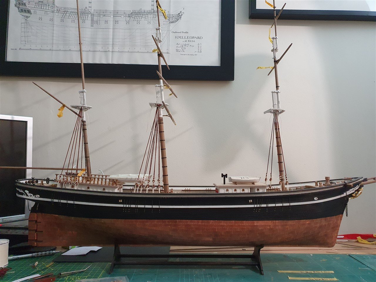
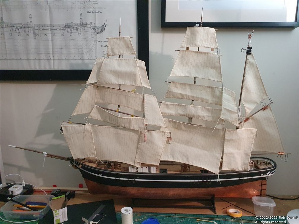
Thank you George I'm either brave or foolish... but nothing ventured, nothing gained. I was inspired to build this model when I saw a model of a clipper with sails in a museum. It was such a sight I couldn't resist. I am a bit nervous about rigging tensions for the stay sails so that they don't sag, which is one of the reasons the bowsprit goes right through to the deck so it will have a really good ability to push back against all that pull. I'll try and make sure the lines below the bowsprit are anchored well too. Inevitably the rigging will end up being an indication of full rigging for the sails rather than every single line, but I still need to work all that out. Plenty still to do
-
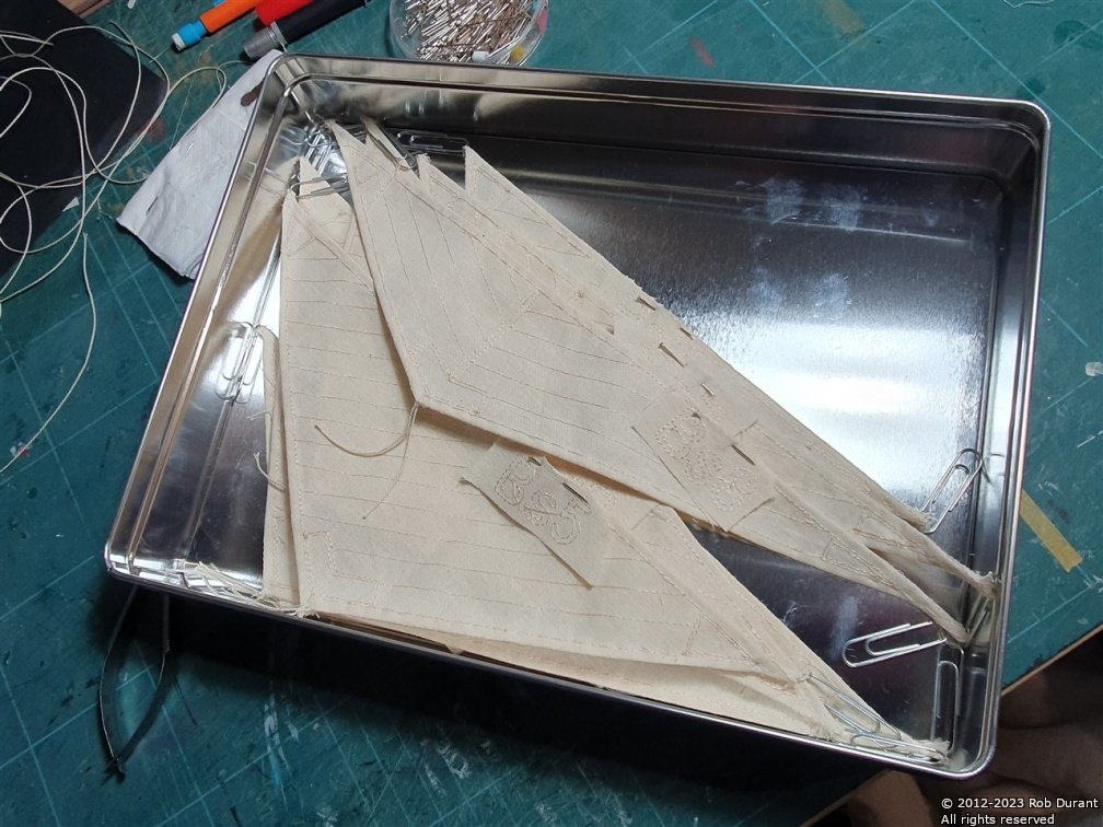
Thanks Rob, and everyone for the likes. Not much to update, really. I've just been steadily working through the sail set, double hemming them. Today I needed to make some more rope, too. Once I got to the stay sails, there's no rigging to hold them at the moment, so I was forced to empty a tin of shortbread to provide somewhere to keep them safe 😁 There are two more stay sails to make, and then four stunsails and I'm done on this stage! Happy building Rob
-
Congratulations. What a beautiful model. Thank you for showing us so much of the process of building her. You have built a model to be very proud of.
- 756 replies
-
- 5
-

-
-
- galleon
- golden hind
- (and 2 more)
-
You're very welcome, AnobiumPunctatum. Glad to have you following along. Thank you for that insight Mark. It's fascinating to hear how much we know about this model. It would have been truly amazing to be a fly on the wall in one of these model builders' workshops.
-
Thank you both. It will be an adventure for sure. I shall be standing on giants' shoulders for this project as Chris designed many of the kits I have built so far. So much of what I know has been taught by him through his kits. Equally MSW has been a fantastic support and encouragement in my journey so far. I'm very excited to see what Chris does with Bristol when he designs his kit of her, and equally excited about facing some of the design challenges he makes look so easy for myself. I'm sure I shall get to the end of this process with a deeper respect for what he and all kit manufacturers do. And he will probably be all done long before I am
-
A little history - Bristol was caught in the great hurricane of 1780, and dismasted along with HMS Hector... the image below is public domain: There's a particularly lovely model of Bristol in the Art Gallery of Ontario, in Toronto; pictures of which can be found on Wikimedia. The link below from the Art Gallery itself suggests this model was built in 1774, making it contemporary - perhaps even the builder's model. https://ago.ca/collection/object/agoid.106283
- 55 replies
-
- 13
-