robdurant
-
Posts
843 -
Joined
-
Last visited
Content Type
Profiles
Forums
Gallery
Events
Everything posted by robdurant
-
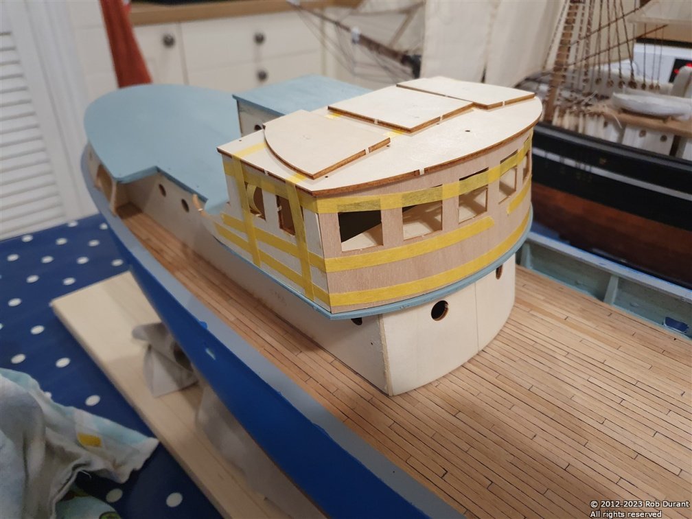
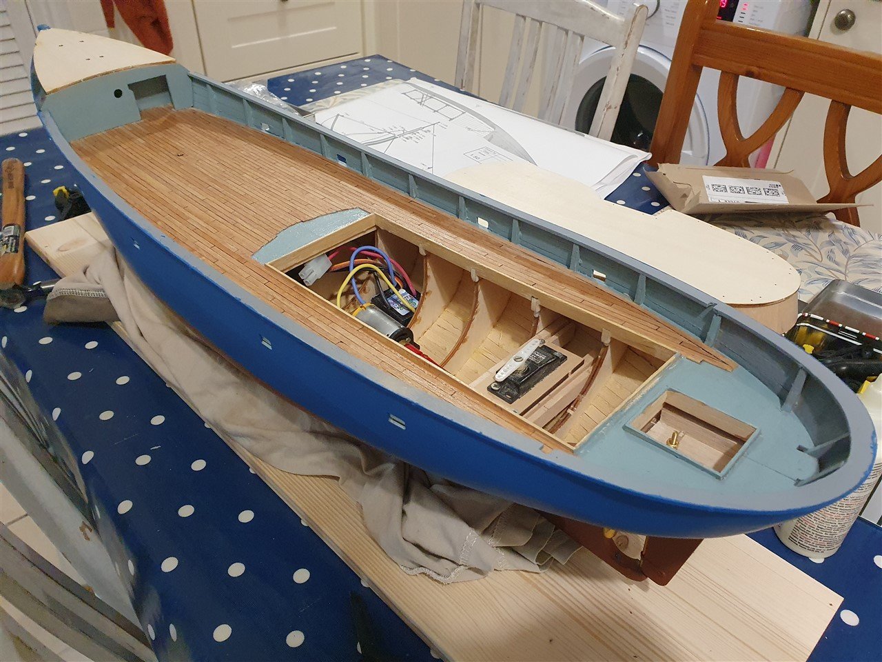
 The weather deck at the bow is filled and painted - with a little fettling still to do, perhaps, but I'll do that once I've added the rubbing strips and details on the outside of the hull. I've also made progress with the superstructure, which now has the makings of a wheelhouse, and the deck sections just behind the wheelhouse are being planked. Here are some photos of her on water... The first time she's been ballasted down to waterline (using sheet lead), and she was dry as a bone inside Thanks for looking in, for likes and for general encouragement. Progress is slow, but definitely heading in the right direction. Rob
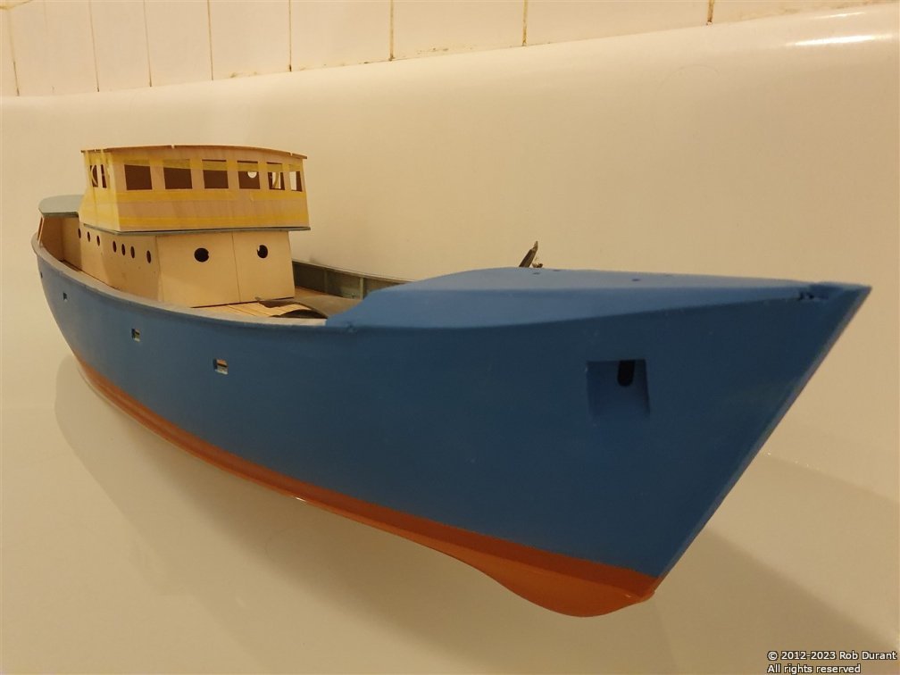
- 57 replies
-
- 6
-

-
- Nordkap
- Billing Boats
- (and 1 more)
-
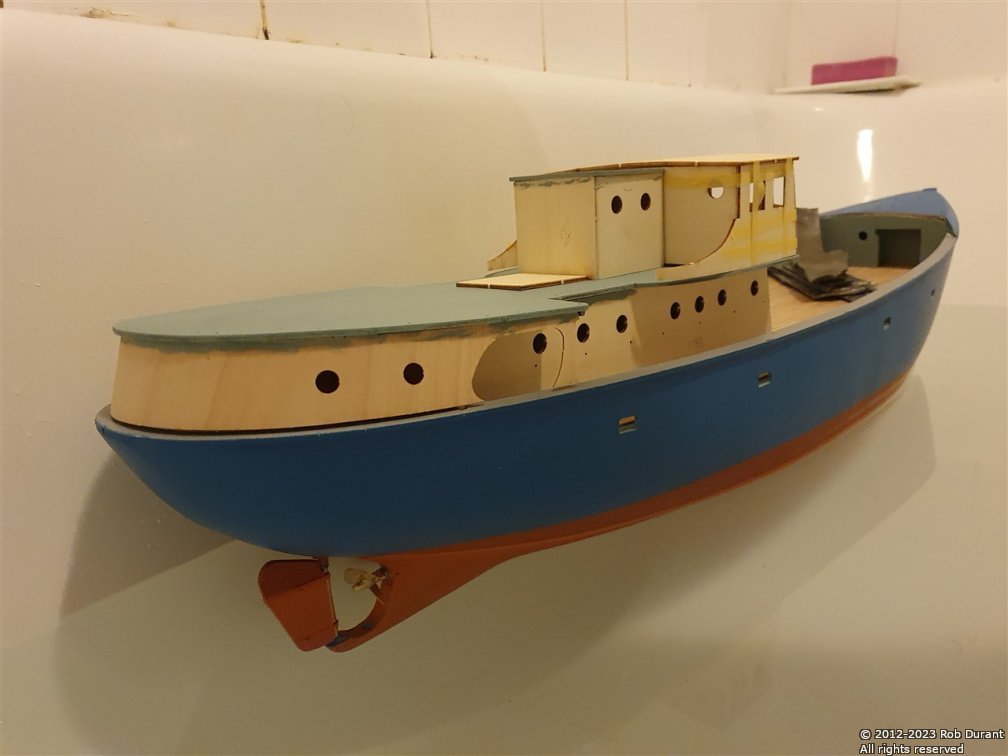
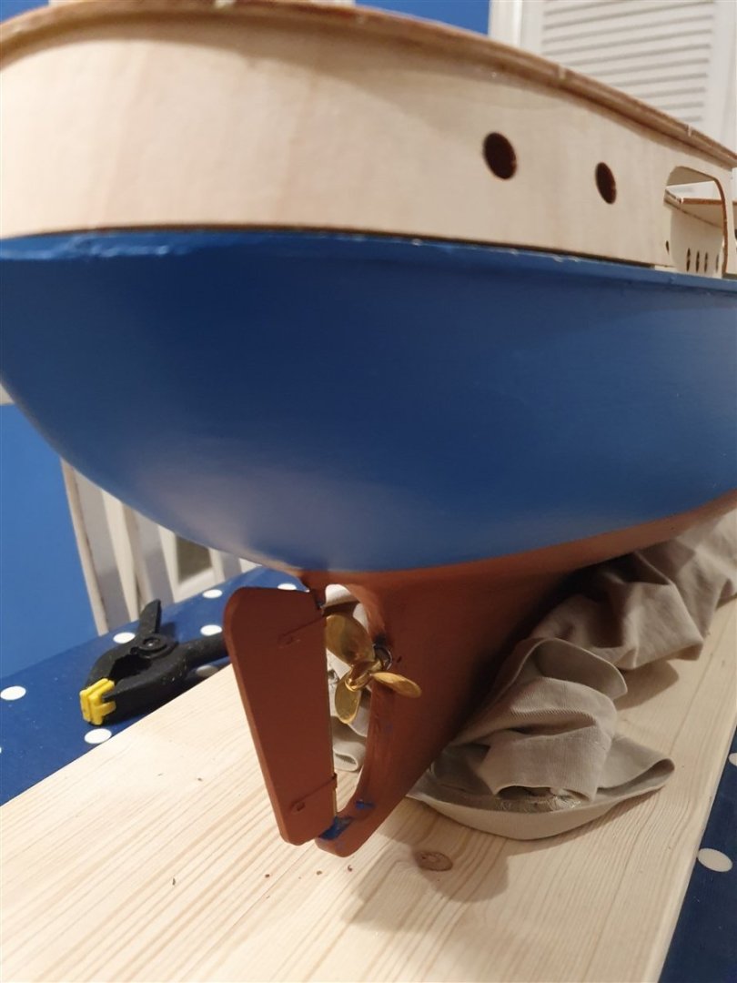
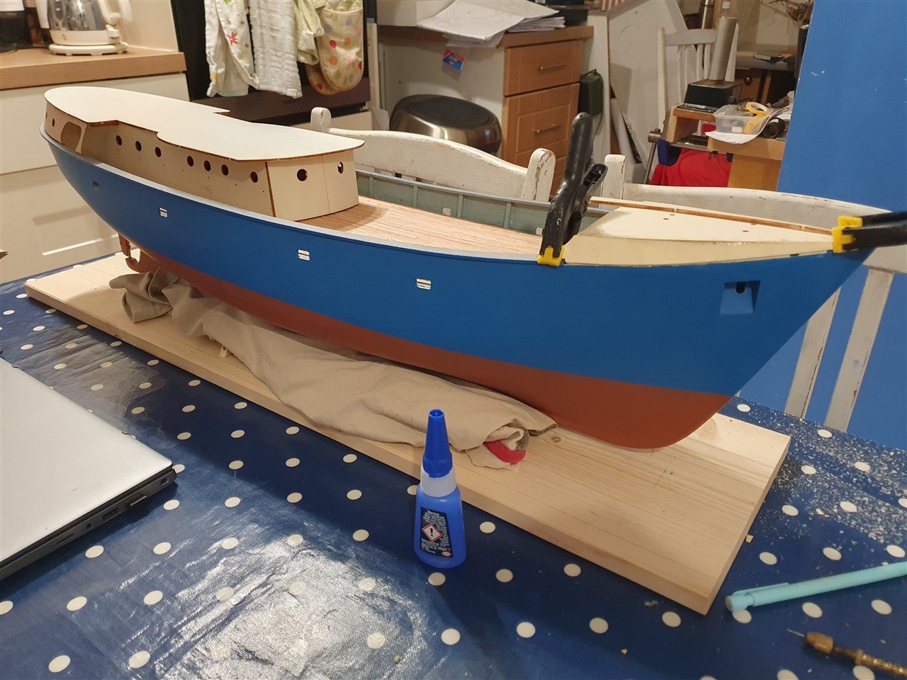
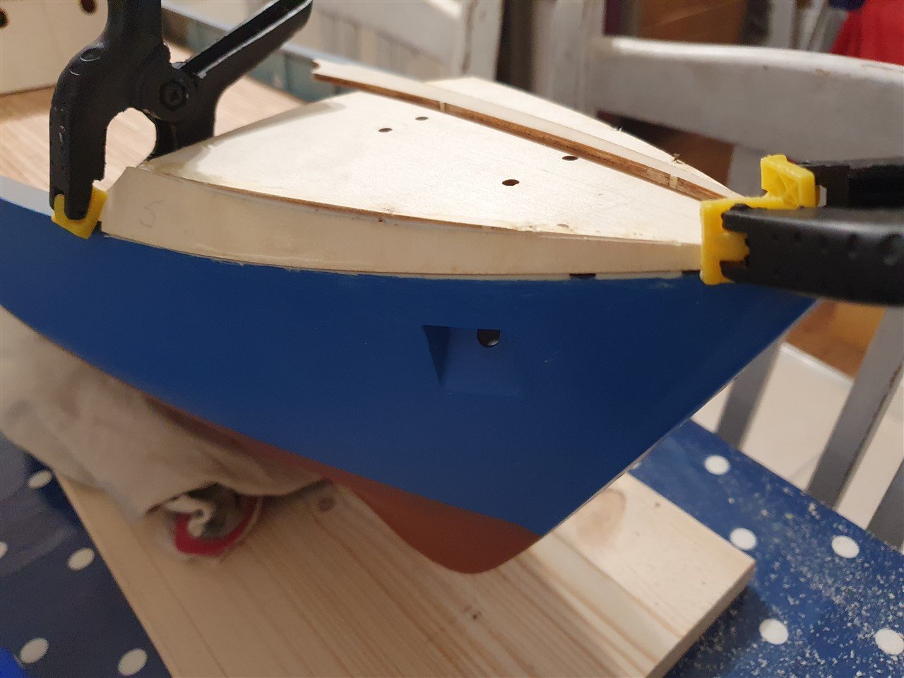
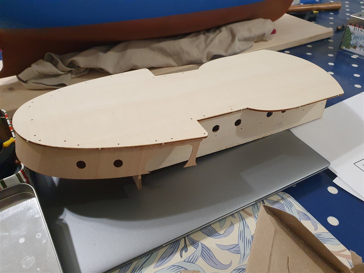
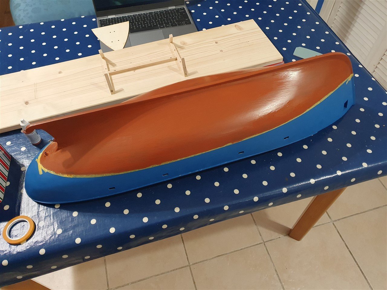
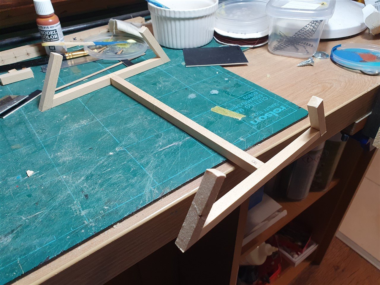
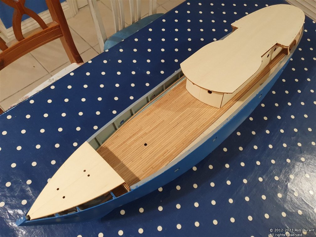
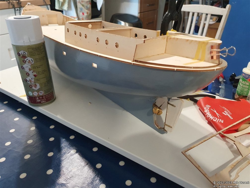
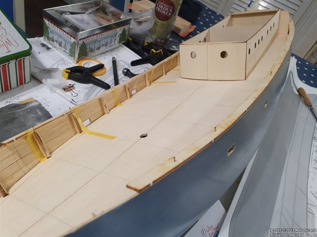
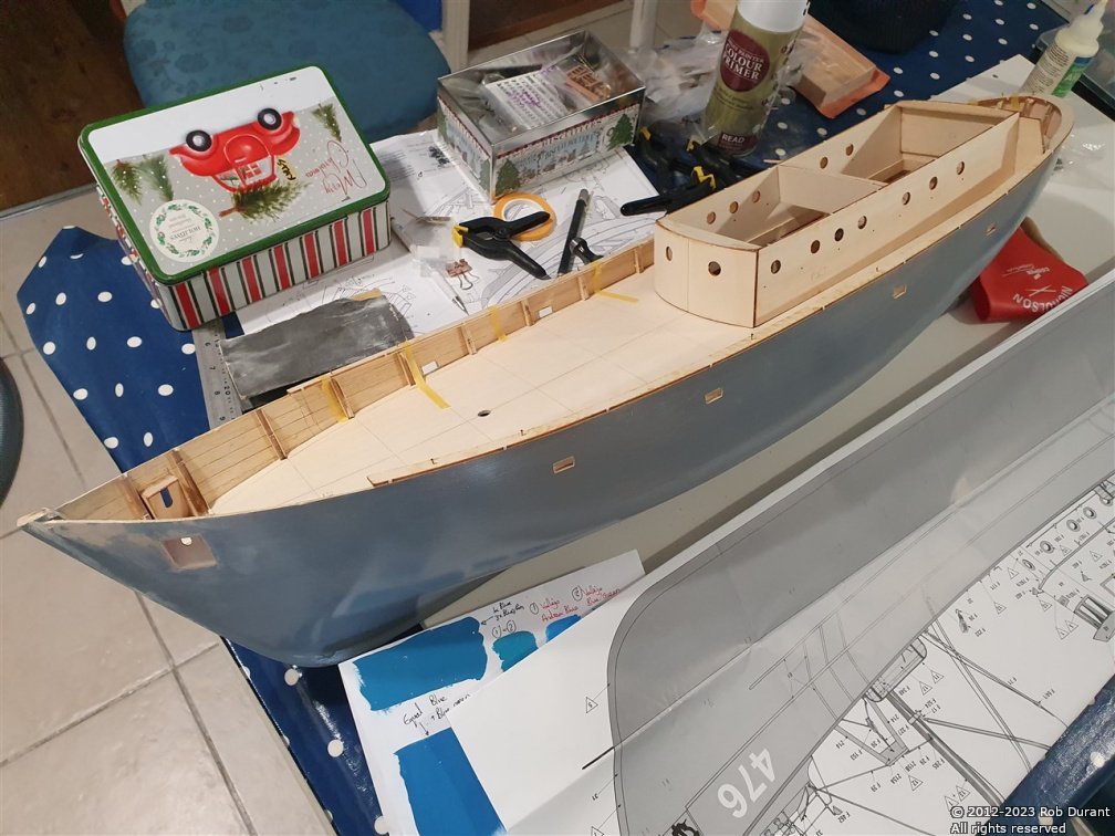
I've completed planking the deck. Once complete, this had a coat of matt varnish (Admiralty paints) I was conscious that I really needed to get on with making the stand, so I bit the bullet, and it turned out okay. The stand as designed is pretty flimsy, and I want it to withstand being taken to a lake to sail, so I've glued it onto the build board, and pegged the parts onto the board with 3mm walnut. I modified the design a little, moving the props for the hull to the ends of the cross pieces, so that they provide greater lateral stability, coming further up the sides of the hull. All in all, it's pretty sturdy now. I'm using an old t-shirt to protect the hull, but at some point, I'll put some pads onto the stand to replace it. Now I had the stand, the front end of the stand could be propped up using some books (2.5 centimetres higher at the bow than the stern), and the waterline marked using a biscuit tin with a pencil stuck to it. Basic, but effective. A spirit-level was placed across the bulwarks to ensure that the waterline was level side to side. Once marked, the waterline was masked off with tamiya masking tape, and the section below the line painted with Vallejo Leather Red. I'm still not entirely sold on the blue - it's darker and not as greeney as I'd intended, but I'm hoping daylight will make it look better. In the not too distant future I now need to add the strips on the hull... these will be stuck on with superglue, and touched up as necessary. The weather deck at the bow was now glued in place. I was really pleased with how this went together in the end. The top was bent using my violin rib-bending iron first to get some camber in it, and then stuck in place, with some pins to hold it in place as it stuck. Once dry, the sides could be added, bevelling the edges to help them fit to the hull and deck. It looked a bit rough, but some sanding improved things massively, and with a little filler, it will look really smart. I noticed that the holes in this deck are nowhere near to centred on the part. I'll probably fill them in and re-drill them. I presume these holes are for the hawse pipes and some deck equipment. I've also added the deck onto the superstructure, ready to begin building the wheelhouse on top. This deck has a lot more curve in it than you'd think, and it was a bear to clamp it while gluing. I eventually got there, but not without a little frustration along the way. The best way seemed to be to clamp it in a few places, so it was in the right position, then to add carpenter's glue, and once pushed into place, add superglue along the inside edges where the deck meets the superstructure sides to tack it in place while it sets. Finally, the rudder had a couple of coats of the Eze-kote water-based epoxy resin substitute that I've used for the hull, and then a few coats of the leather red to match the hull. Looking at that photo, the cap rail's going to need some more attention before it gets its final coat of black. I can do that at the same time as I clean up the weather deck at the bow. Thanks for taking an interest. Another bouyancy test is called for soon, I think Rob
- 57 replies
-
- 6
-
-
- Nordkap
- Billing Boats
- (and 1 more)
-
Looking great... the character is in fact a Greek capital lambda (L) (the following image is public domain from wiki images) The Lambda represented Lacedaemon which was the Greek for Sparta.

-
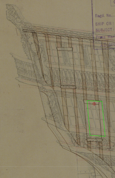
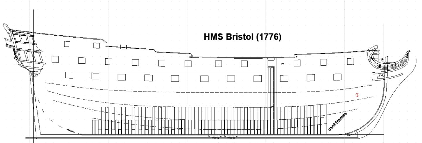
I mentioned earlier in this thread that the framing plan for Portland didn't quite match up with the profile plan for Bristol, and @scrubbyj427 and @allanyed and @AnobiumPunctatum, you've been kind enough to continue the discussion prompting me to think about this whole task in ways I hadn't before. My horizons are broadening! Looking back at the plans, and doing some measuring (the CAD I'm drawing is at 1:1 scale for the original) I now realise that the door is only 3" out of place, so what seemed like a gaping difference when I looked at it, is pretty close all things considered. Here's a picture of a small section of ZAZ1749 (Bristol profile) and ZAZ1719 (Portland framing plan) overlaid to show the difference. The green square marks the quartergallery door as per the Bristol profile.
-
Interesting. I'm using ZAZ1719 for the framing and ZAZ1749 for the profile of Bristol... this is the plan with the decoration on it. It hadn't occurred to me that the framing might have changed so drastically between Portland and Bristol. Without evidence to the contrary I would feel inclined to follow the framing plans for Portland as closely as possible, I think?
-
Perhaps something like this? 1mm half round styrene. Only .1mm over scale... a brush with some sandpaper, or drawing it through a .9mm gap would make that difference.. and being HIPS you could warm it and it may go round the corners? You could laser cut a wood jig to shape it on inside and outside while gluing, perhaps? I used crayon as a release layer to stop the plastic glue sticking the melted plastic to the wood. https://www.scalemodelshop.co.uk/1-0mm-half-round-evergreen-240-p11588/?gad_source=1&gclid=CjwKCAiA9ourBhAVEiwA3L5RFqOc_8N-nCzcjOCucuzaV3MVNrqOCPTypKI8P3kbAJKTe01YS3INgBoC7GMQAvD_BwE
-
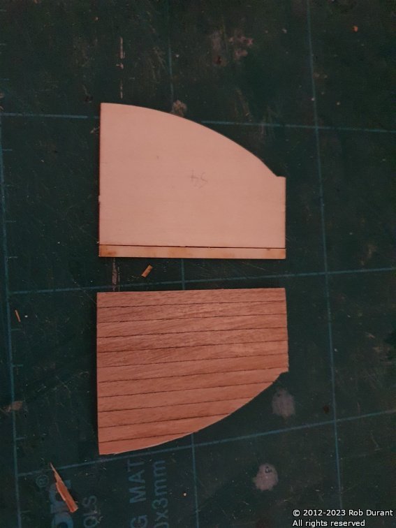
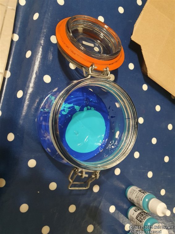
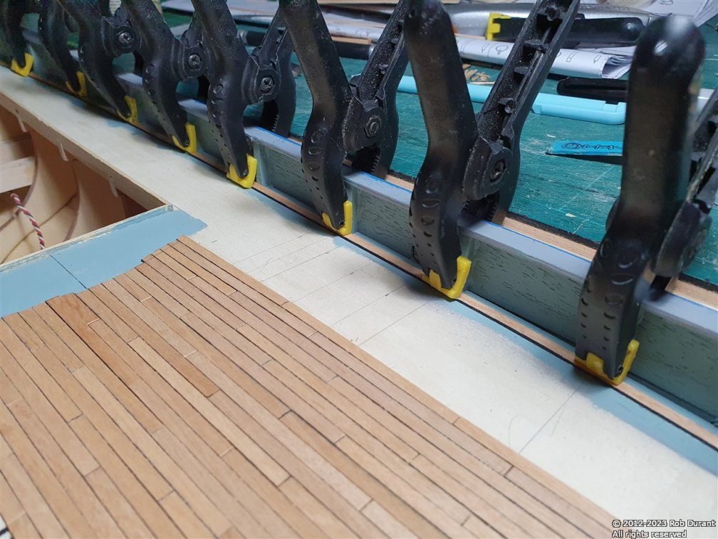
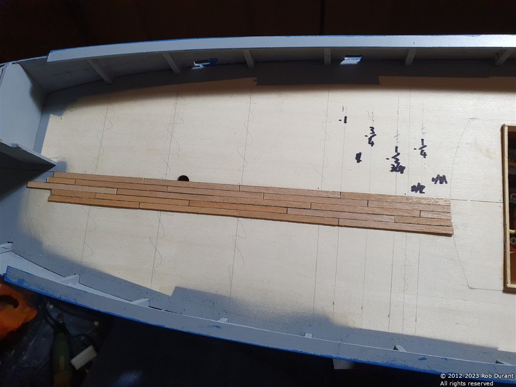
Ten more days have given me time to mix up some blue paint for the hull - I've used whole bottles of vallejo paint so that I can re-make this colour if I need to... it's four bottles of blue, four bottles of blue-green, and one bottle of light green-blue. I've did a test on the planking (which is left over from Barque Stefano), to make sure that Admiralty (Caldercraft) Matt Varnish didn't make the sharpie I used to add caulking, run... it didn't. I also painted the insides of the bulwarks light green-blue, and the top of the superstructure will be this colour too. The planking was stuck in place with carpenter's glue. Once varnished, it should be fine for fairweather sailing. The edging of the planking was achieved by adding a margin plank, which was glued just inside of the bulwark posts. I'm pretty pleased with how it's turned out. Here are some pictures of progress so far. (There are still a few lines of planking to be added on each side to finish the job.)
- 57 replies
-
- 7
-
-
- Nordkap
- Billing Boats
- (and 1 more)
-
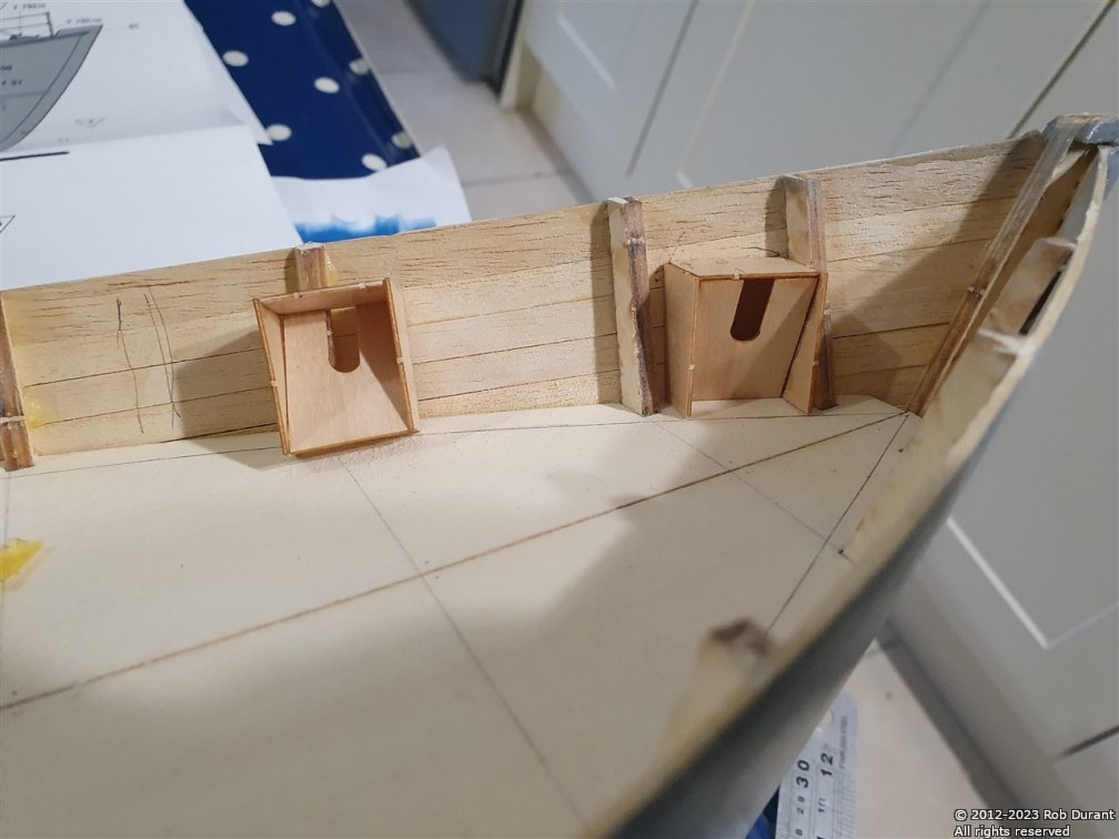
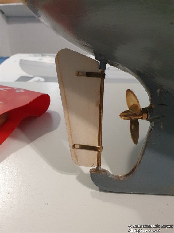
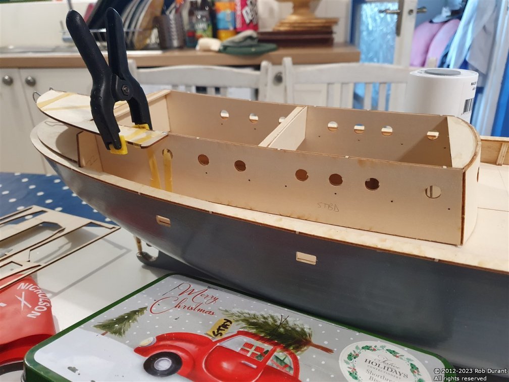
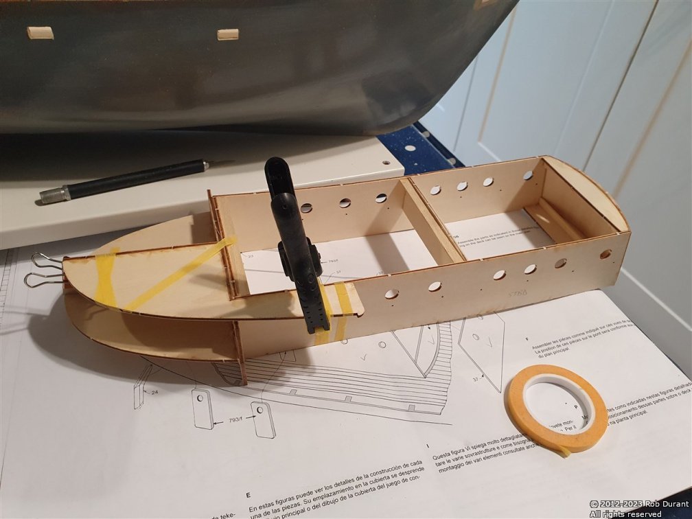
My day off today has given me a good shot at getting some things done on Nordkap. I've opened up the scuttles (?) and built and installed the recesses on either side of the bow for the anchors. Each hole was started with a drill, and then opened up carefully with a craft knife and then a file. Once glued in place, the anchor recesses had any gaps filled with a wood, superglued in place, and then sanded flush. I've also installed the cap rails... These were temporarily pinned while they glued, as otherwise they don't sit flat on the tops of the bulwarks. Built and installed (temporarily) the rudder... before I glued the two wooden parts together, I bevelled the front edges to create a v-shape that the rudder post could sit in. Once glued together, the rudder was sanded to make it narrower at the rear - I always think rudders look slightly strange when they're chunky at the back... it just looks wrong to me. Then it was time to go into town a get a pasty for lunch! I also made some progress with the bow weather deck and stern superstructure (this is easier once the cap rails are on, as the height of the rear area of the superstructure is determined by the cap rail (to ensure there's no gap). Finally, it was all cleaned up, and another coat of the Eze-kote resin was painted on to seal all of the exposed wood on the outside of the hull (and in the scuppers). I need to do some testing to see whether I can put Eze-kote over the deck planking, or whether I'm better off with just matt varnish... Thanks for following along. Rob
- 57 replies
-
- 7
-
-
- Nordkap
- Billing Boats
- (and 1 more)
-
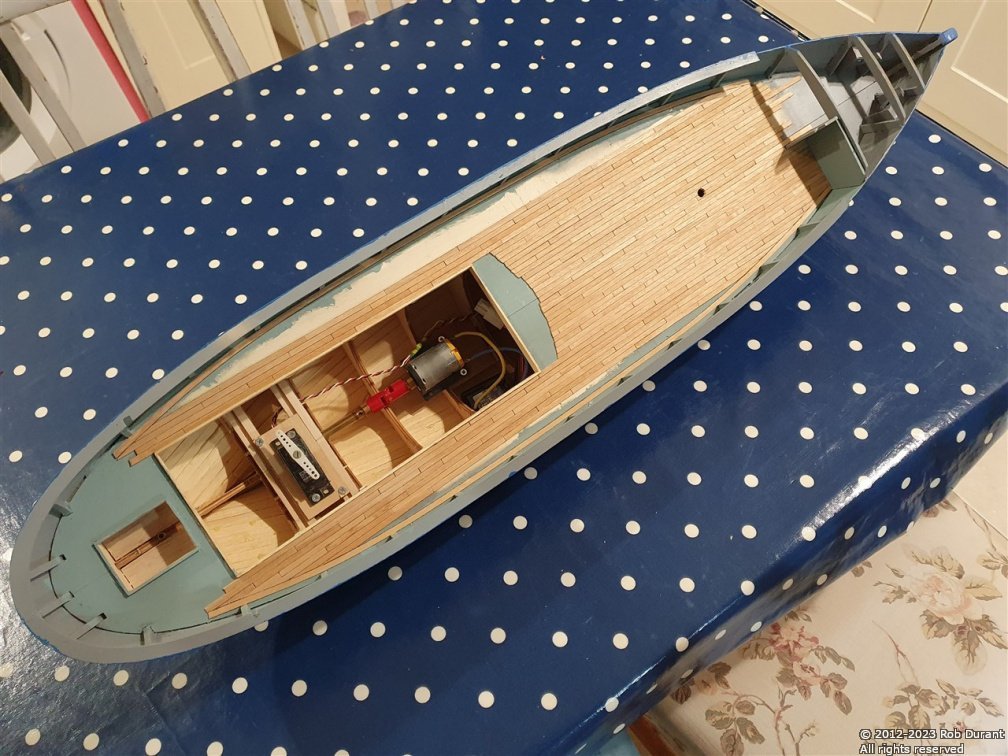
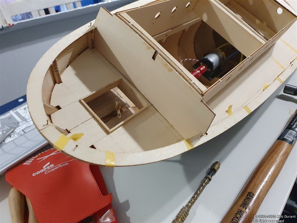
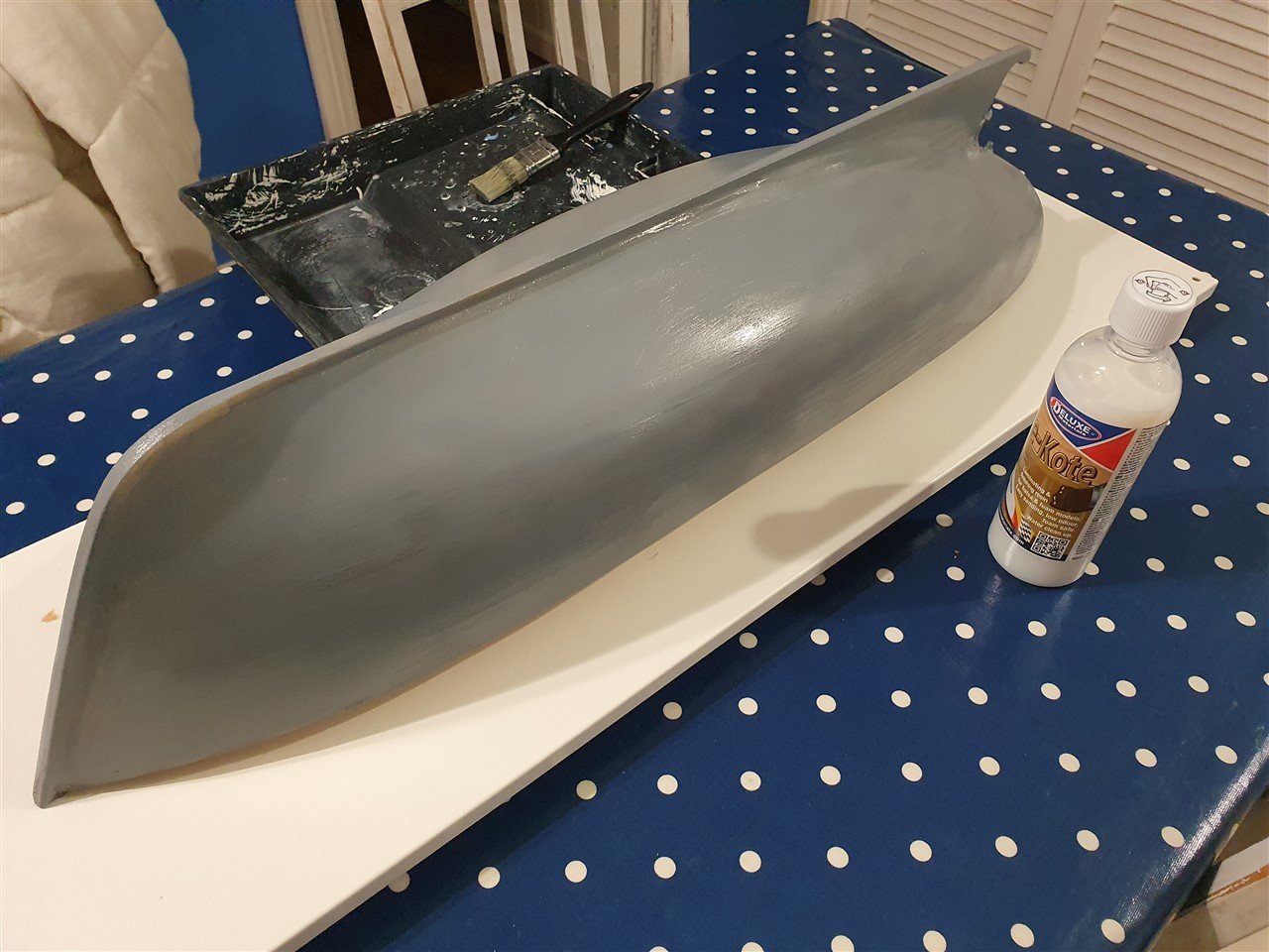
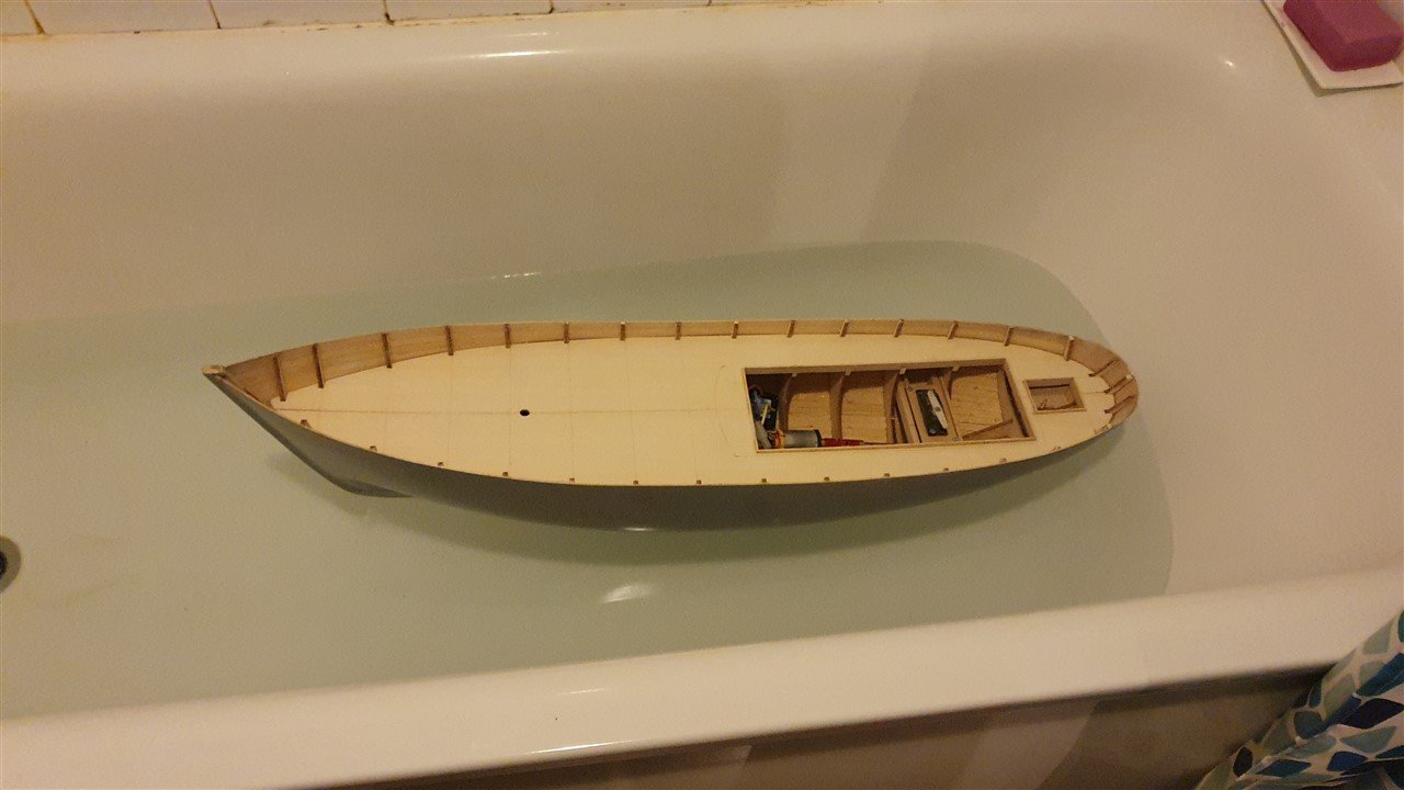
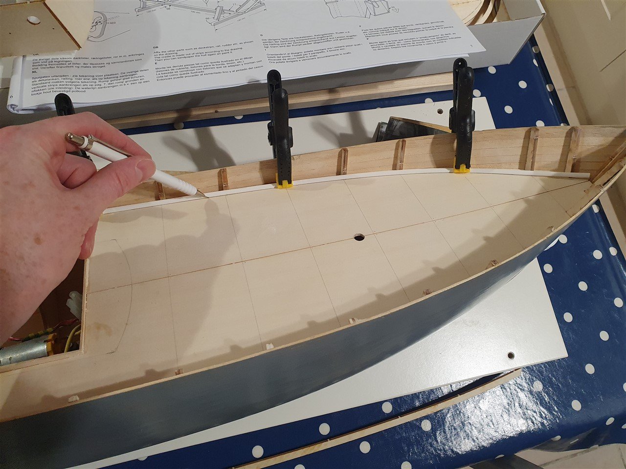
So... here's the progress. I did a lot of reading up, and the whole question of whether to use fibreglass along with the resin, or whether the resin itself is enough seems to be very much a Marmite one... I've opted to try without the glass. Many have said they've had success this way, and it certainly seems to have done the job from all I can tell. Time will prove me right or wrong I am grateful to you, @Ian_Grant for your advice, and you will absolutely have the rightn to say "I told you so" if this heads south as a result of my decision 🤣 Lots of prep, four coats of Eze-kote, with very light sanding in between, and the hull has taken on a lovely sheen - re-installing the prop and rudder shaft with some grease, and it was time for a test in the bath. It's years since I've done this, and I thought I'd ask my son to give me a hand... Here are the results. There was a brief false alarm as we mistook some bobbles of carpenter's glue for water coming in, but thankfully it was all a false alarm. She's dry as a bone inside. Here are some photos of her. In addition, I've begun marking out the deck for planking. The strips of planking provided are pretty rough, but thankfully I have a shedload of tanganyika left over from my HMS Diana, Caldercraft kit, that I'll substitute. Before I do that, I need to cut out the bulkwark openings (the anchor port, and the scuppers), and then paint the edges of the deck that will remain unplanked. Onwards and upwards! As always, thanks for looking in, and for the likes, advice and encouragement. Rob
- 57 replies
-
- 7
-
-
- Nordkap
- Billing Boats
- (and 1 more)
-
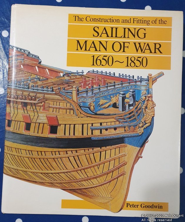
Yes, I also own a copy. I've been working from that for the framing plan. It pretty much lays neatly over the Bristol side profile plan, although the caprail height towards the stern is considerably different (raised higher in Bristol), and the transom posts are at a slightly different height, even though the quartergalleries are at the same height... Considering the complexity of these drawings, they really are magnificent achievements in themselves. Thank you for the prompt, though. I also received this in the post today, which I'm expecting to be very helpful... It was £4.50 on AbeBooks, and only £2.50 postage, so an absolute no-brainer! Much happy reading is in store! Rob
-
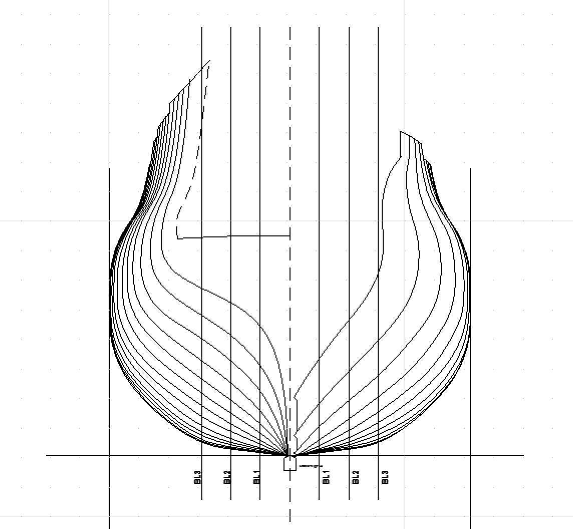
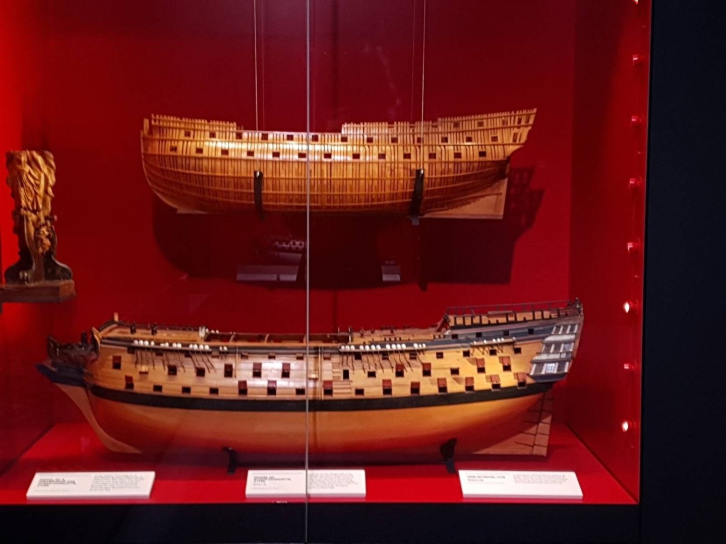
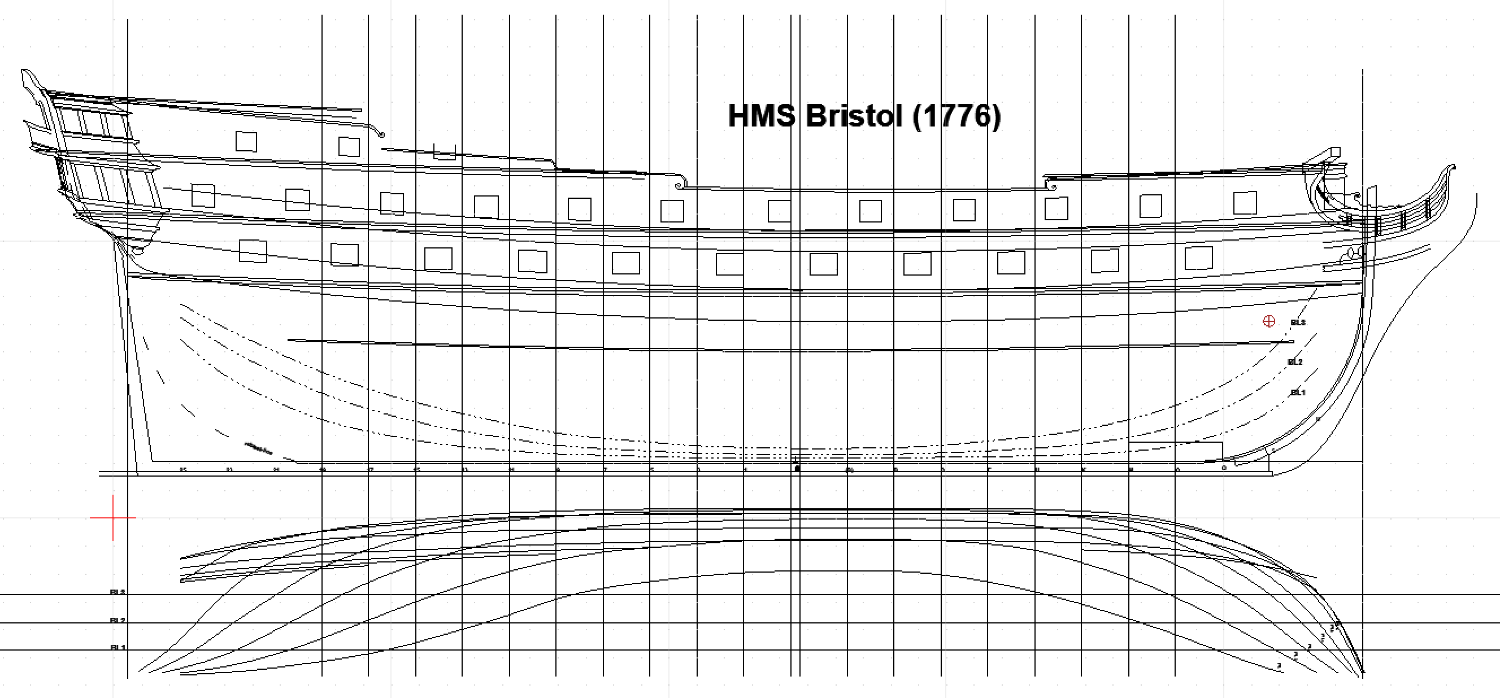
Time to revisit this thread... I haven't stalled, but I have been spending lots of time thinking, reading and revisiting how I've approached this. I've gone right back to scratch with all I've learned, and redone the drawings from the plans, and I'm much more happy with the results (shown below)... they're all works in progress, but reconciling the profile, half-breadth and body plan, suggest that the fairing process is going well so far. Plotting the buttock lines went perfectly with no changes required, which was very satisfying indeed. I'm indebted to Wayne Kempson for his article on this site (Drafting Ship Plans in CAD) - it's been a massive help. So - initial lines... There are decks, the two wales, buttock lines, and the rabbet line at the stern... As the plan stands, I'm now hoping to build this as a fully framed model without any planking, except possible the wales, much like a model (I think of Centurion?) I saw in Chatham a few weeks ago... (Apologies for the quality of the photo) Beginnings of a frame plan... (this will need redoing, but it gives some idea of the flow of the frames) And the body plan... My next step is to confirm the heights of the caprails...

-
What a stunning model, George. A wonderful achievement!
- 602 replies
-
- 1
-
-
- Flying Fish
- Model Shipways
- (and 2 more)
-
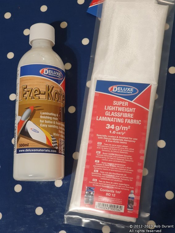
That's some cool looking stuff you've got there, Ian... and that book looks great, too. I've been really enjoying watching your progress with your Roman warship. A magnum opus, to be sure! Okay - so here's the plan for waterproofing... Having sanded the hull some more the other day, I noticed that when I hold the hull up to the sun, I can see not only thin areas where the planking had gaps, but more than that, I can see pinholes where the planks and the filler haven't completely bonded... Suffice it to say, if I were to try and float this boat right now, the water would be getting in right away... So... I've had a bit of a look around, and this is the plan. It's called Eze-Kote, and it's designed specifically as a finishing resin, but it's water based, so clean up is easy, and it's low odour - it's a much nicer chemical to be dealing with. In addition, I've bought the lightweight glass fibre they recommend to go with it. I wanted something very light weight, so that it forms round the hull shape nice and easily, and is relatively smooth out of the box. Last time I used fibreglass resin, I used automotive stuff, and both the results (I used fibreglass mat, not knowing that was a disaster in the making), and the resulting headache and rough breathing for a few hours after were enough to tell me I hadn't taken enough / appropriate precautions, so I'm hoping this experience will be far less unpleasant. I'll let you know how I get on, but there's a little more prep to be done first round the prop shaft and rudder post. I'm working on the assumption that good prep is always time well spent. Thanks for looking in, and for the advice and encouragement. Rob
- 57 replies
-
- 5
-
-
- Nordkap
- Billing Boats
- (and 1 more)
-
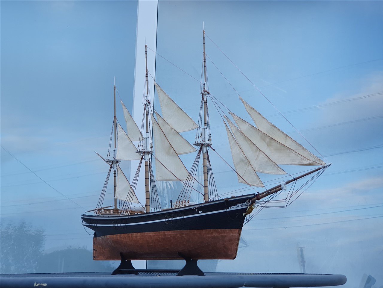
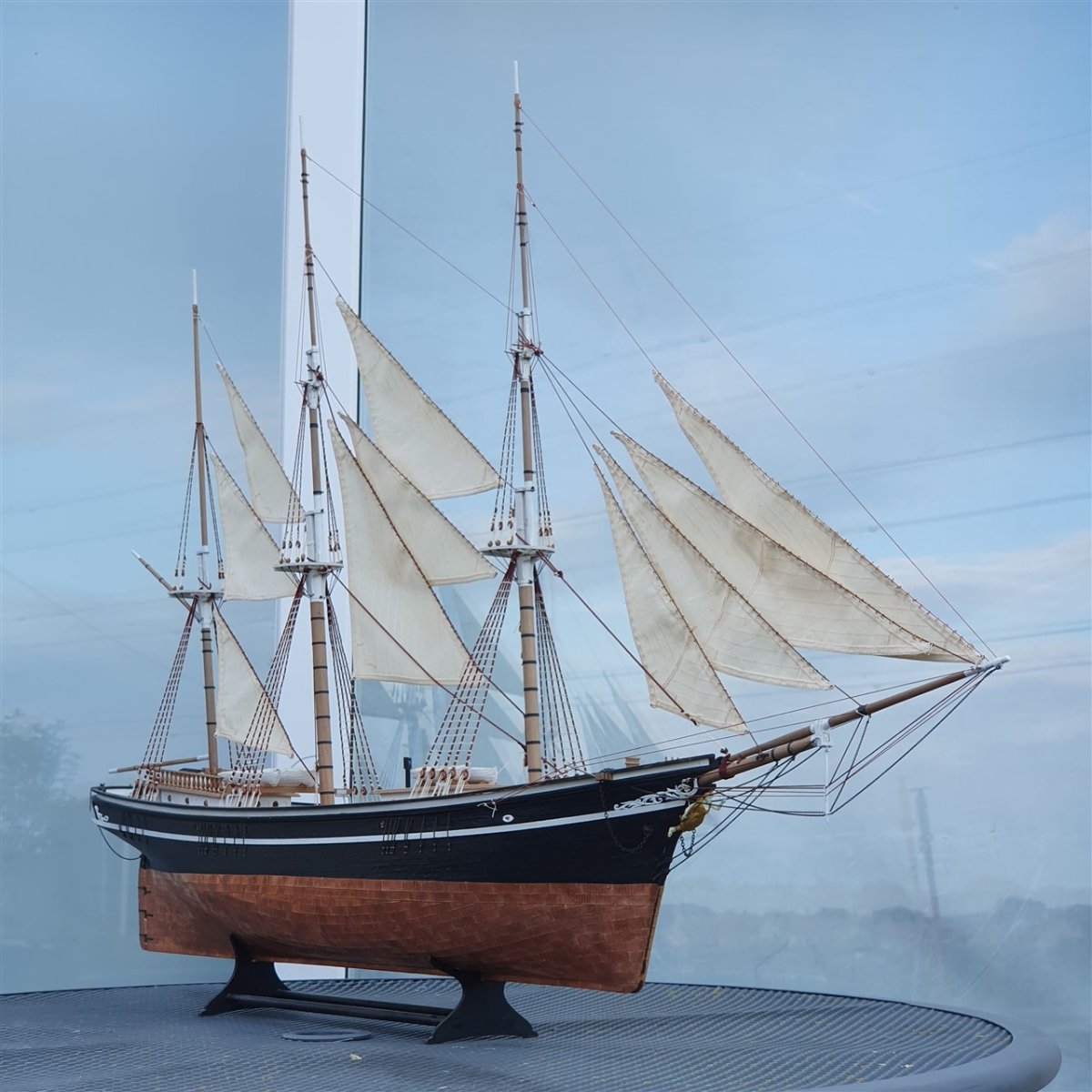
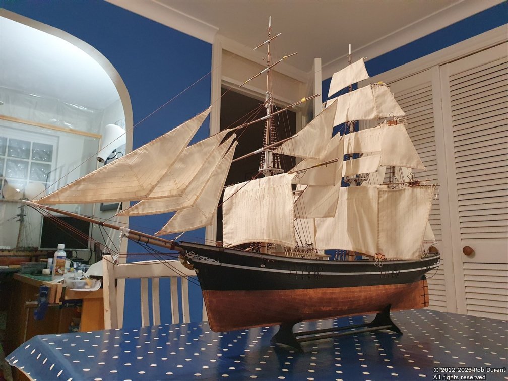
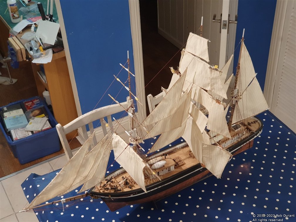
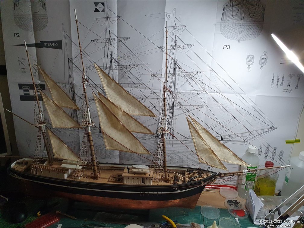
Hi everyone, Three weeks later, and I've had another good day to work on Stefano. I finally made and died some more .5mm rope for the standing rigging, which allowed me to complete the backstays. I've also got some more work done on the yards, adding eyelets, blocks, and bending the forecourse to the main yard on the foremast. Again, this has caused the model to take up significantly more space on my desk, but it feels like we're on the home straight now as we move towards running rigging. I counted, and I think I have 8 sails left to bend to yards / stunsail yards. There's a lot of tidying up to do with rope ends fixed with watered down PVA (a big advantage of making your own rope with DMC cordonnet thread, as it's natural, not synthetic), and trimmed to make them neat. Thank you so much to all of you who've hung in there through what has proved to be a lengthy build Here are a few shots of how she stands right now. Happy building Rob
-
That deck looks great. Thanks for sharing this build, I'm enjoying following along.
- 68 replies
-
- 2
-
-
- Sanson
- Artesania Latina
- (and 2 more)
-
Aah yes.... I seem to remember they were called "Bob's boards", or something similar... and my Tamiya Grasshopper II had one in it... Back in the days when you had a race to use the RC before both transmitter and car ran out of charge. I seem to remember it had a ceramic heat sink to get rid of all the wasted power (not a sign of great sophistication!) Something like this... ? Times have certainly moved on That brings back memories, for sure! Many a happy time was spent zipping it round the garden and collecting wet grass all over it until it crawled to a stop!
.thumb.jpg.bd9852c1e1806265697a25764d2d3829.jpg)
-
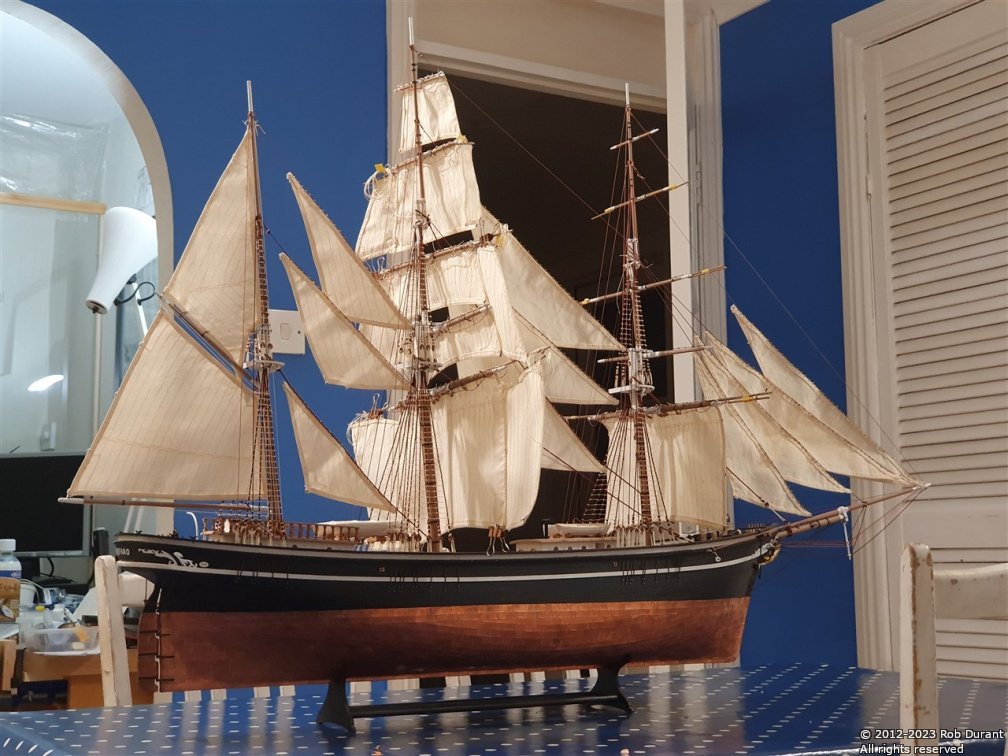
@rwiederrich - It truly is. I had a good day yesterday working on Stefano - I've added the mast hoops to the Mizzen topmast - these 9 hoops were formed from brass wire and chemically blackened. Then they were put in place on the mast and thread tied to them ready to attach the sail. I added the running rigging holding this sail in place, and then went on to add the spanker sail. Now that these fore and aft sails are in place, I can add the backstays. So far I've added the starboard foretopmast backstay. Thanks for looking in, and for your kind words and encouragement. Getting to this stage is really spurring me on to complete Stefano, but there's still a fair bit to do. Rob
-
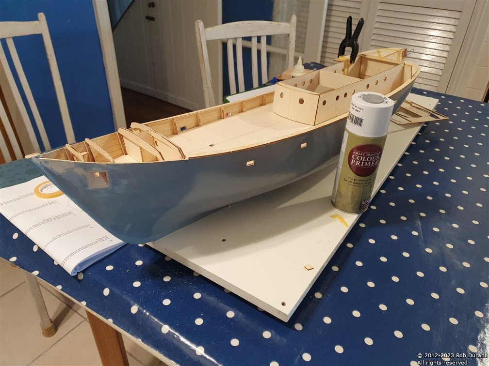
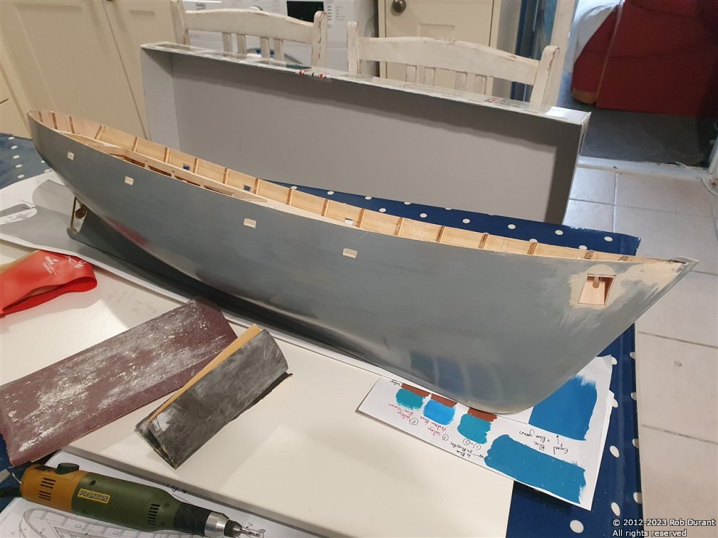
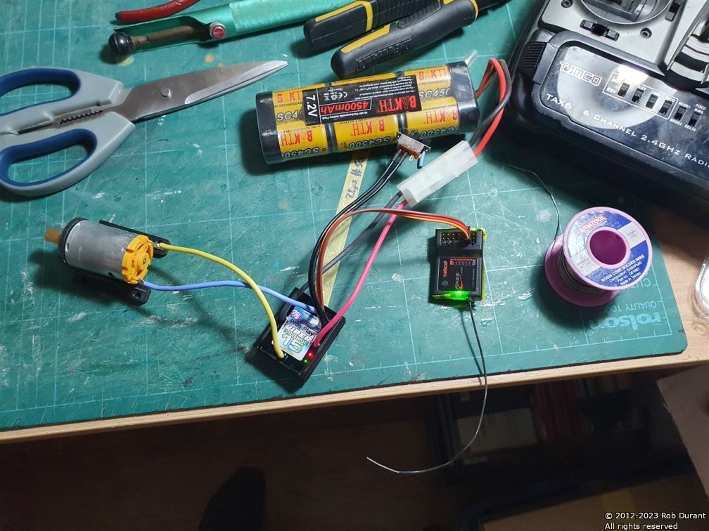
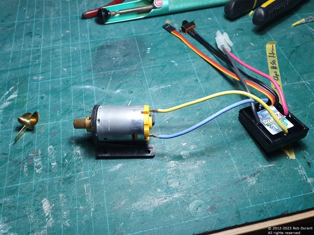
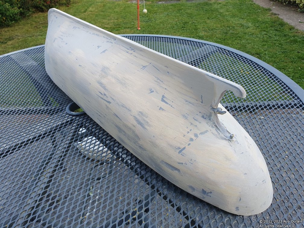
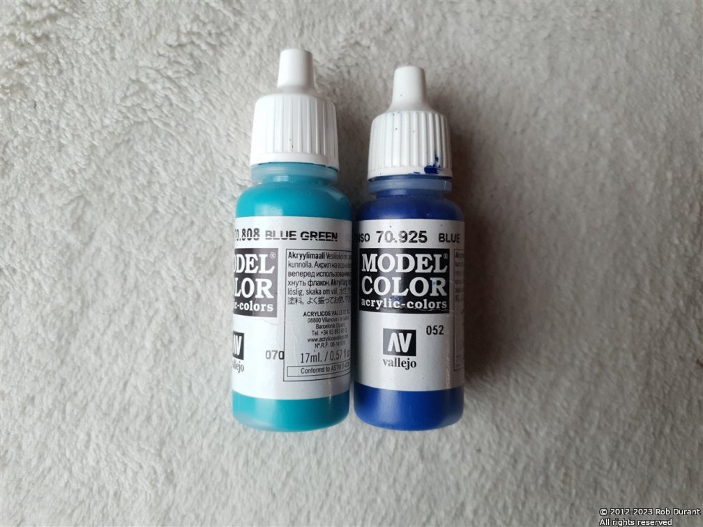
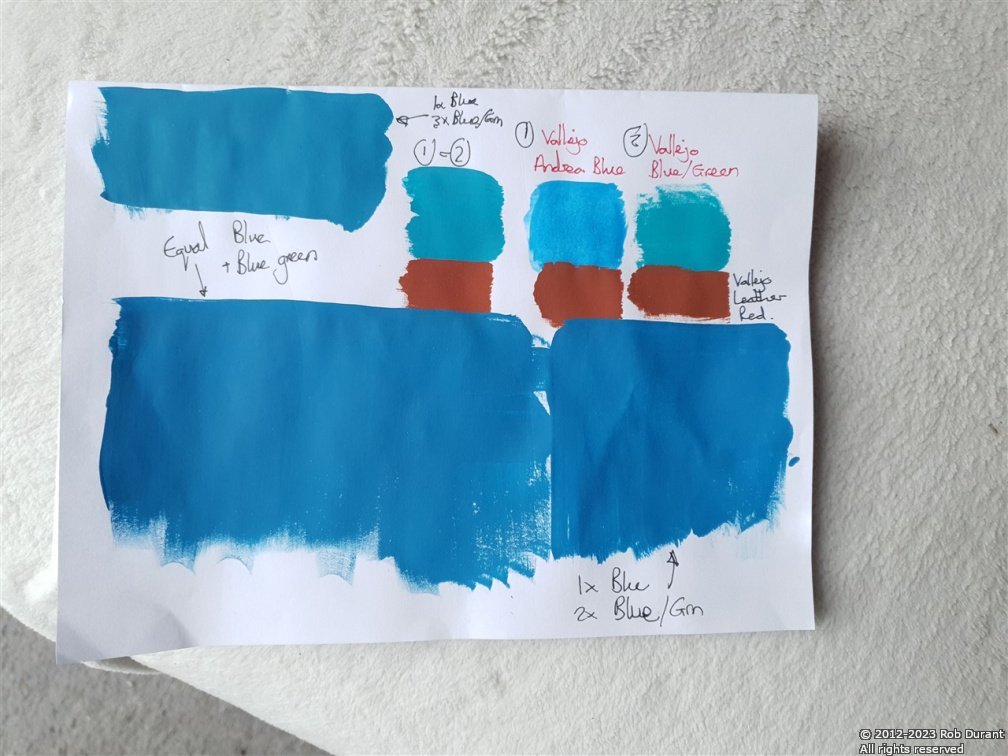
Thanks @Ian_Grant - yes, I need to source some light fibreglass cloth. I'm hoping to get a really smooth hull before I fibreglass it, so that the tidying up after is as limited as possible. I've gone through a few more rounds of filling / sanding, and it's really starting to look quite neat - these photos are from half way through the process. In-between filler and sanding, I put on a coat of grey primer so I can see where the peaks and troughs are... The new speed controller arrived, so I've set up all the electrics and tested them. They'll do the job nicely. Things have moved on since I last made a radio controlled model, and this clever speed controller works out which way is forward based on the first direction you push the throttle stick on the radio control! Clever stuff! I had to solder a new receiver plug onto to the servo for the rudder, but otherwise, all very simple and easy. Rudder is channel 1, and Throttle channel 2. I tested the motor with an AA cell before I soldered on the speed controller to check that the prop would rotate in the correct direction - (clockwise as you look from the stern). It ended up as shown below. I've also been looking at what colour to put on the hull... I don't want a bright blue, but something a little more towards the teal end, and somewhat more subtle... To that end, I've been experimenting... I need to re-run these experiments on grey primer, as I suspect the mix will need to change, but the picture below gives some idea of the colour I'm looking for... It's a 1:2 / 1:3 ratio of Vallejo blue/green and Vallejo blue... I tried Andrea Blue but it was too light. I'm looking for something like the top left tone... Admittedly that tone will look different on each screen that displays this, but I've been looking at this in daylight and under daylight bulbs, and I'm pretty happy with the tone in real life. Having a 1:2 / 1:3 ratio makes it very easy to replicate should I need to. I just get the appropriate number of bottles and mix them in their entirety. Big thanks to everyone for looking in Rob
- 57 replies
-
- 3
-
-
- Nordkap
- Billing Boats
- (and 1 more)
-
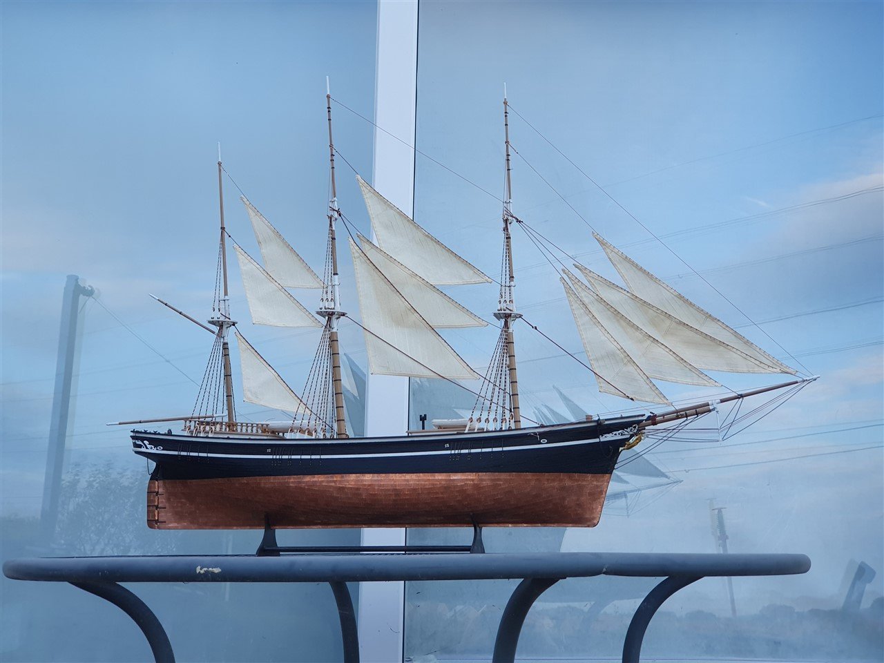
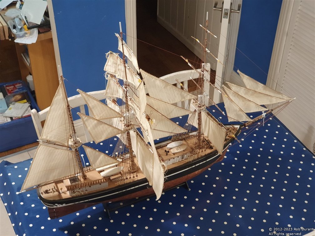
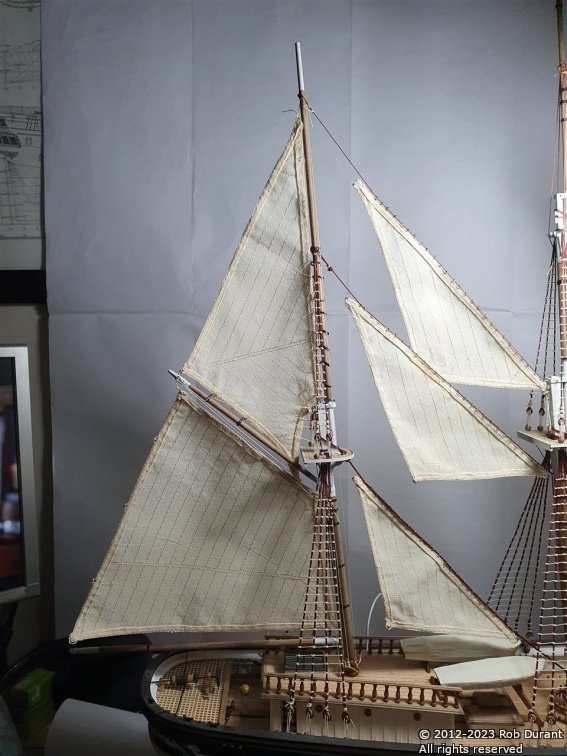
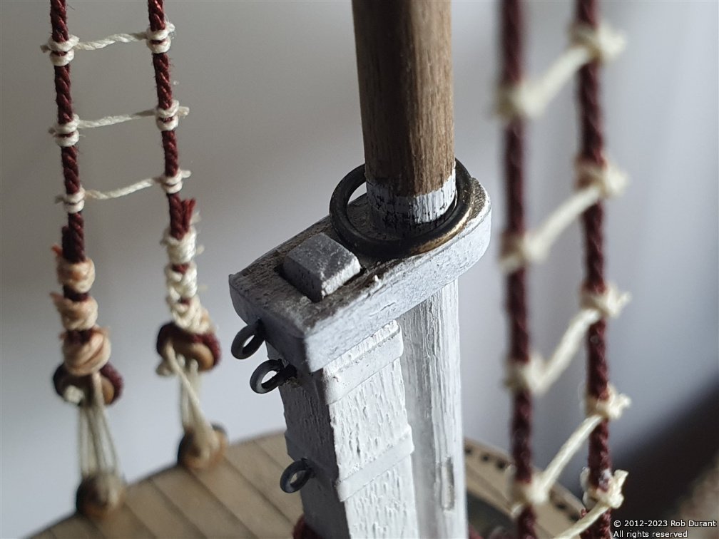
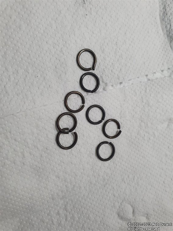
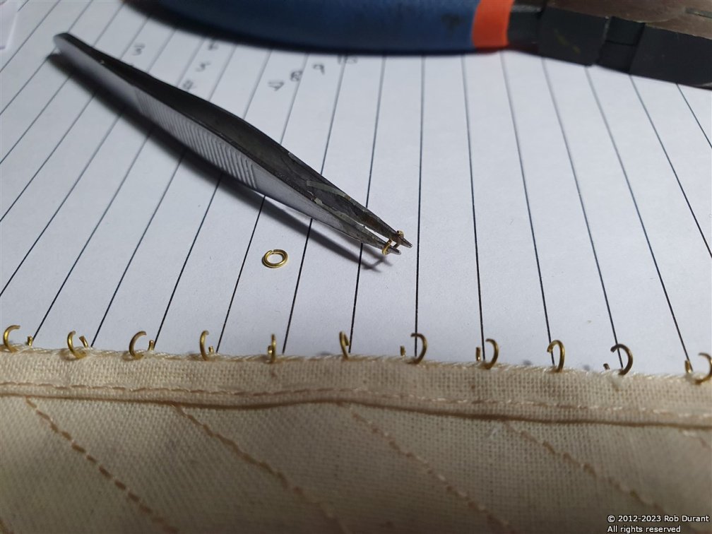
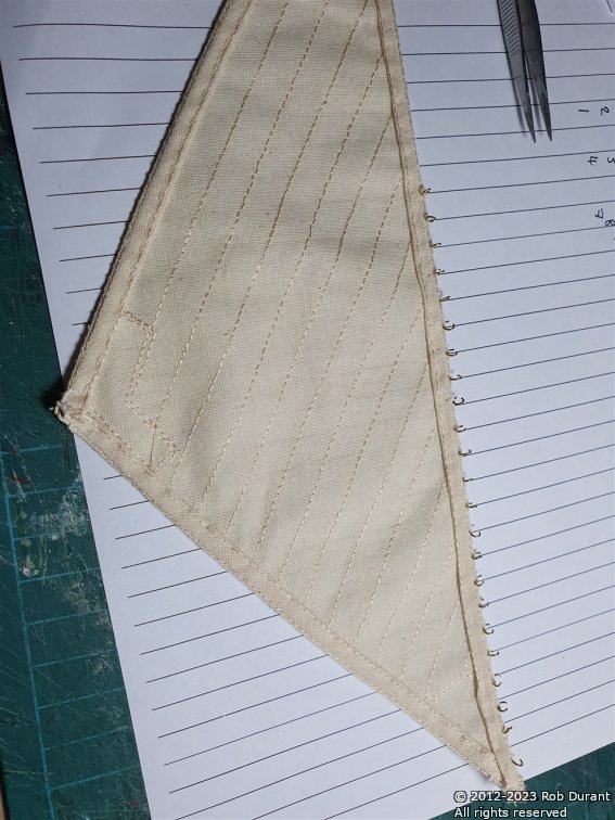
After a very enjoyable day off, more progress has been made. I've been attaching the stay sails... These are attached with tiny rings which are opened up one by one, and threaded between the bolt rope and the sail... The sail is then lifted into position and the rings closed one by one. I've found that a pair of tweezers is essential for holding and opening the rings, then a pair of pliers with grooves helps to grasp the ring to close it (a smooth pair of pliers won't stop the ring pinging round flat, and that led to considerable frustration at the beginning of the process. I've got quite good at it now. There are two staysails waiting to be attached. I wanted these in place before I added the backstays, so that I still had easy access to the centreline of the model, where all this takes place. I think that's proven to be the right approach. Thanks for all your comments, and for showing an interest Rob
-
I would be very interested to hear that. Hope it proves satisfactory they're hulking great models when they're rigged (of course that's part of the appeal)
-
Sadly, the cost of cases is prohibitive for such a model - last time I looked it would cost over £500, and the companies I talked to were unwilling to take on the work - it being of too large a scale for them to want to try delivering the case once it was made... Time will tell, but I do have a willing recipient, so I suspect Stefano will end up on display out of a case... I haven't got Ethalion into a final case - she's behind a perspex screen so that I can see her, at the end of my boat building desk. The enjoyment is absolutely in the building for me, so if someone comes along, admires her, and wants to put her in a case, I'd probably be tempted to pass her on
-
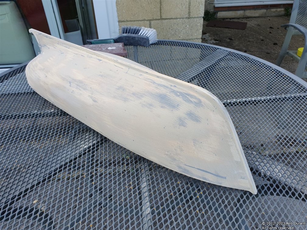
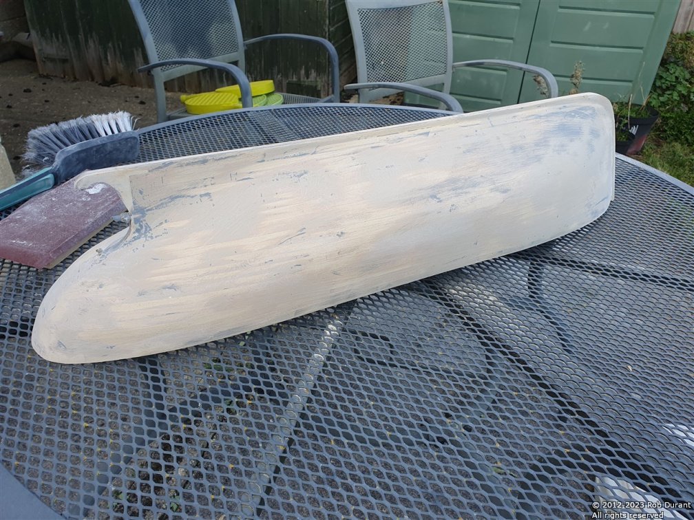
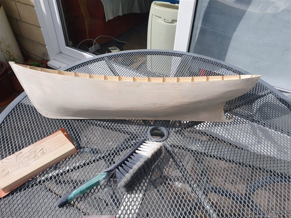
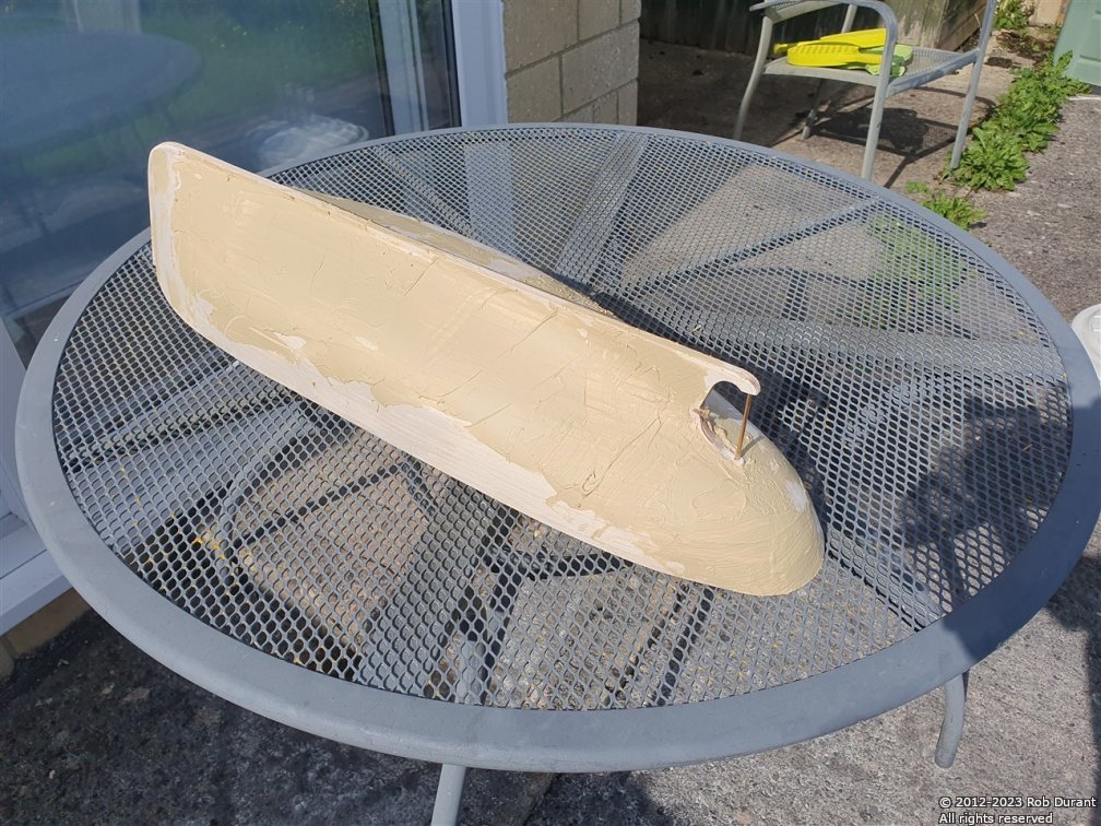
So... it seems like something of a crime to cover up planking, but I've used some car body finishing filler (polyester-resin) to begin making the hull watertight... and now begins the sanding... and more sanding... and then filling... and then sanding... and (you get the picture...) First comes the filler... Then, after 20 minutes it's set enough to be sanded... and it's worth sanding it sooner rather than later, as it only gets harder... I'm using a very coarse paper glued to wood to ensure I don't sand peaks and troughs into the hull... This is most certainly a job to be done outside, with a mask on, and with the door inside shut... the amount of dust is considerably... It's a start. And it suggests that I will, indeed, end up with a watertight hull. Thanks for looking in and for the likes and encouragement Rob
- 57 replies
-
- 4
-
-
- Nordkap
- Billing Boats
- (and 1 more)
-
Thank you for your kind words, David.


.jpg.175ad6e61b99e125d62c0df76a231fd1.jpg)