
HOLIDAY DONATION DRIVE - SUPPORT MSW - DO YOUR PART TO KEEP THIS GREAT FORUM GOING! (Only 13 donations so far - C'mon guys!)
×


robdurant
-
Posts
842 -
Joined
-
Last visited
Content Type
Profiles
Forums
Gallery
Events
Everything posted by robdurant
-
 Looks like you're well set for an enjoyable build. Hope you don't mind my following along.
 -
When you add pictures to your post, so they show in the attachments box just below the text, but then you don't insert them into the text, they are automatically added at the end of the post instead... you can remove then if you want by editing the post, hovering over that attachment in the box under the post text and clicking the black x on the top right corner of the attachment you wish to remove. You've done a beautiful job with this model. The varnish has brought out the wood really nicely. Looking forward to seeing all 4 masts stepped... she'll be even more impressive.
- 58 replies
-
- 3
-

-
- Spanish galleon
- Billing Boats
- (and 1 more)
-
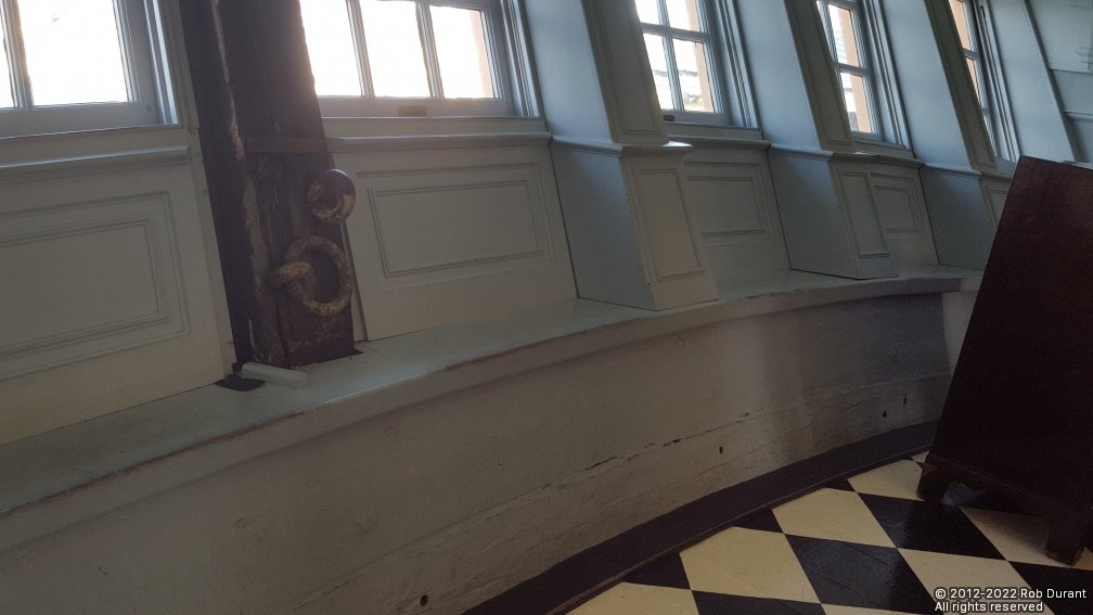
Here's a photo I took in Victory which gives some idea... for some reason I didn't take any wider angle pictures in there...
-
Hear hear
-
Excellent description and a very clever method. Thank you David. Rob
- 310 replies
-
- 3
-
-
- Diana
- Caldercraft
- (and 1 more)
-
Apologies, as I may be the only one who is terribly slow on the uptake. Would you mind describing how you use this dipping trough? Specifically whether you wrap the rope round the bobbin and lower it in as a batch, or whether you use the bobbin to hold down the rope as it is pulled through from one side to the other? I face exactly the same task of colouring standing rigging, so I'm very grateful to you for describing your experiments. I'm also thrilled to hear that you've made the breakthrough with the colron wood dye. Those wouldings look great Thanks in advance Rob
- 310 replies
-
- 1
-
-
- Diana
- Caldercraft
- (and 1 more)
-
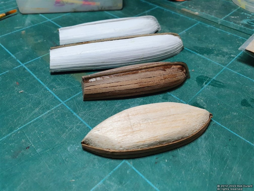
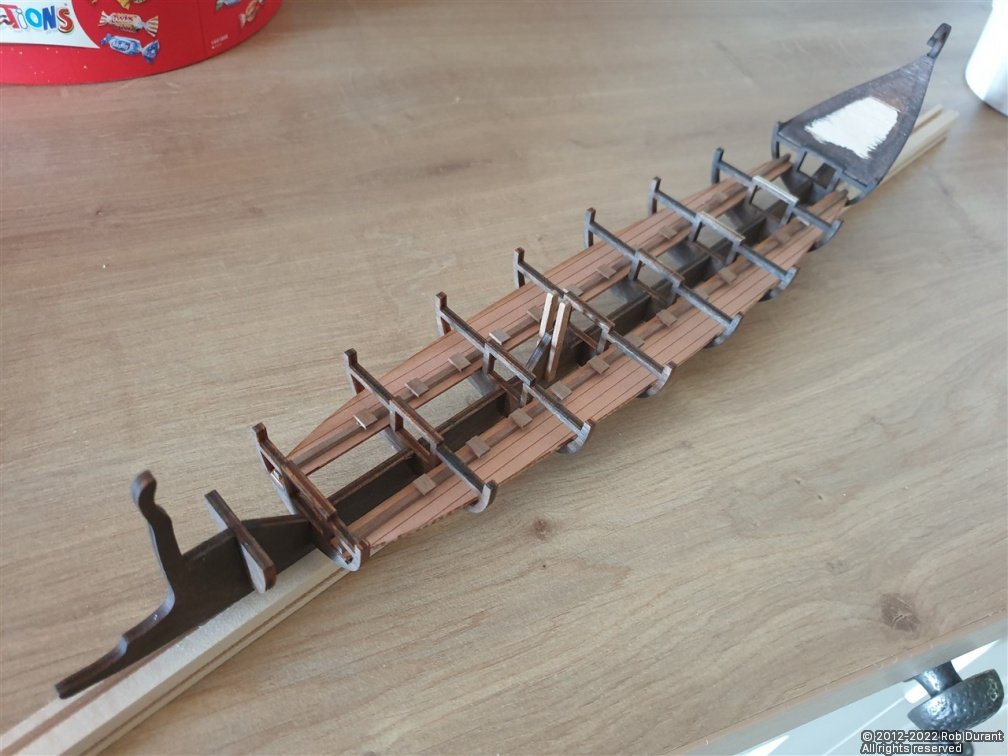
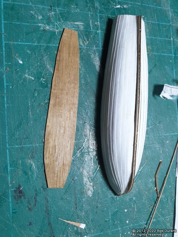
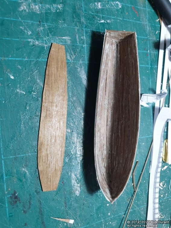
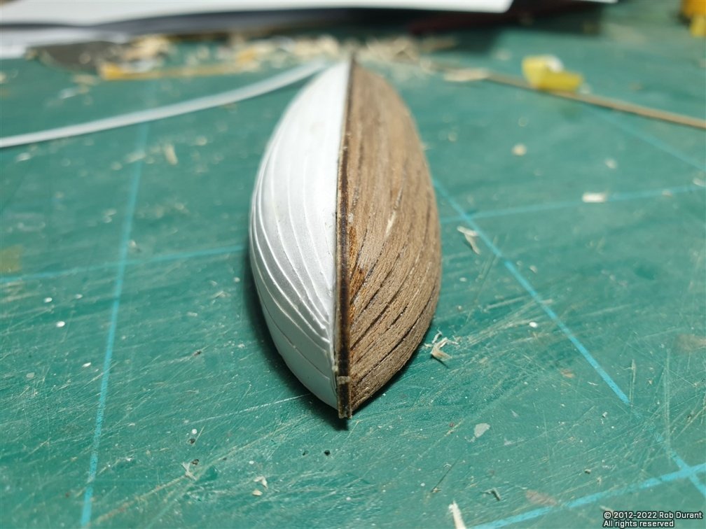
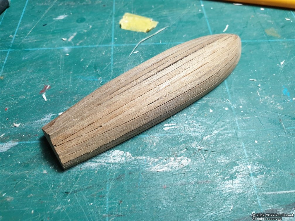
Hi all, Thanks for all the likes. A very brief post today. I haven't stalled completely, but holidays have caused the shipyard to slow to a crawl. I've now planked three of the ship's boats with the thin walnut, and covered two of those with paper "planking" to create a clinker effect. In addition, I've made a start on a Dusek Bireme, as a much more portable holiday project that I can take away with me (she's 39 centimetres from bow to stern). There are excellent build logs on that kit already on the forum, so I'm planning on just enjoying that one as a build, rather than posting a log, unless anyone particularly wants me to put up some pictures. Here is one of progress so far, however. I've got a link to the pictures I'm taking of the build in my signature (or click here "ἈΘΗΝΑ (Athena) (6th Century B.C.) Greek Bireme").
-
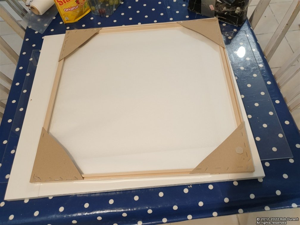
A new post, because this progress is completely unrelated to the posts above. I've been working on making sails with modelspann... I've made a frame to allow the tissue to be prepared from wood with card corners to strengthen in... And I've been working on the ship's boats again, finishing off the planking of 71.1 the largest boat, hollowing it out, and adding clinkering using paper on the outside. The next step with these will be to detail them (the part on the left above will form the floor of the boat, but before that goes in I need to add ribs. I'm pleased with how it's going so far. Right - sorry for so many updates... I'll try and keep up a bit better in future.
-
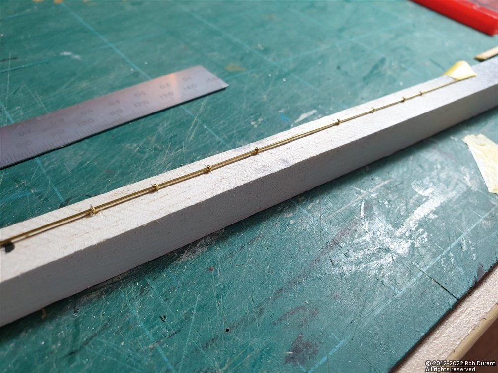
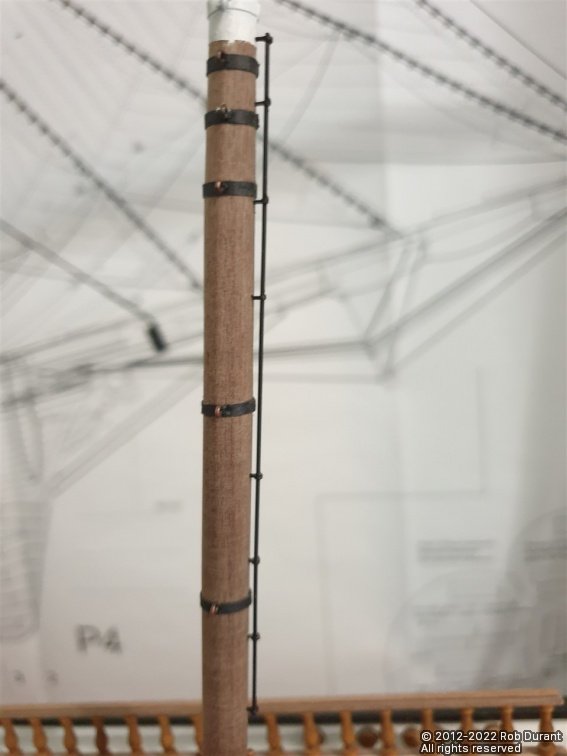
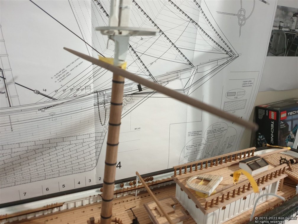
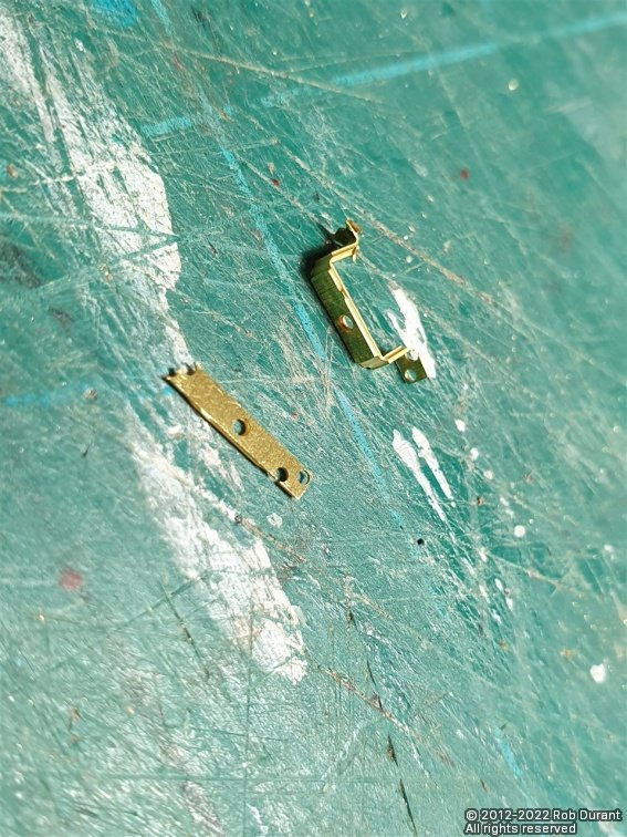
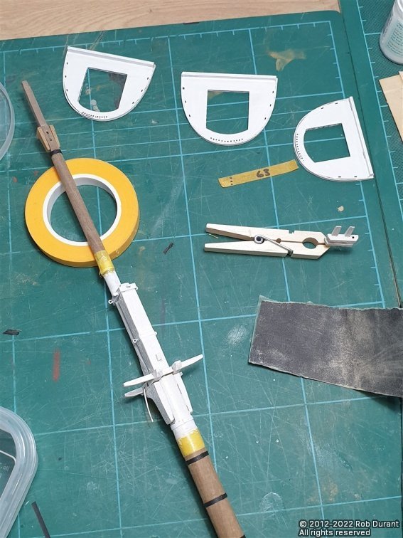
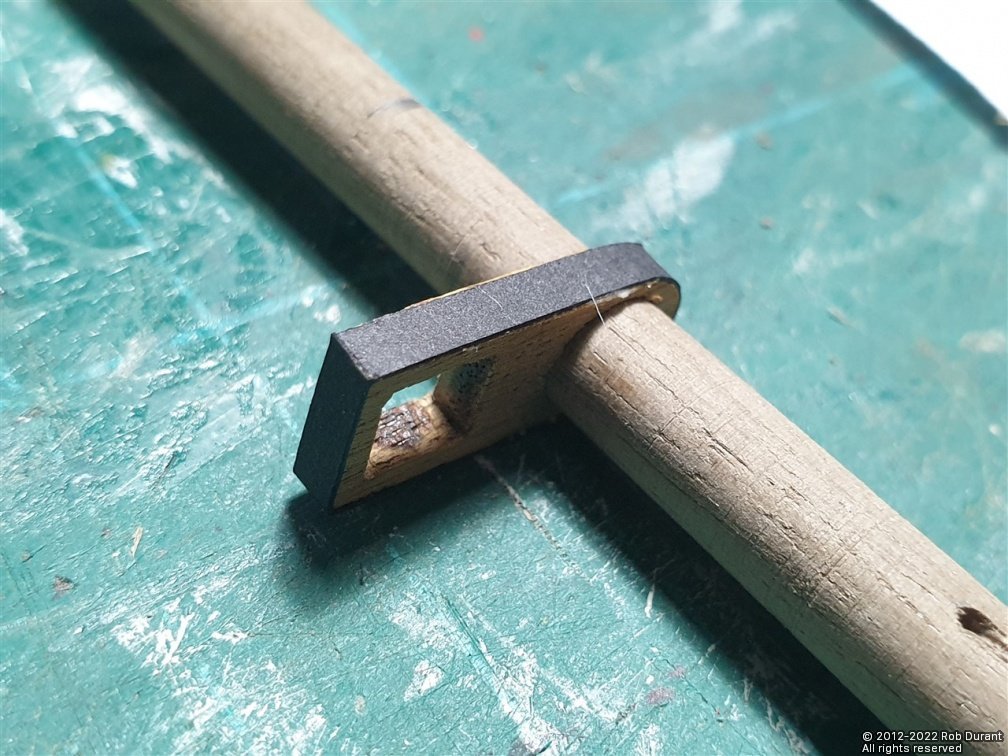
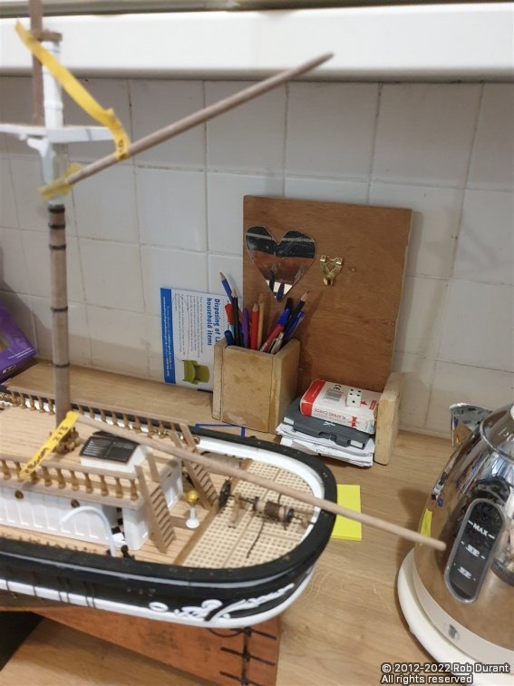
Finally, I made up the rail that forms the attachment point for the gaff sail on the mizzen mast. This is made from brass photo etch eyes and brass rod, and marked the positions onto balsa which was used to hold the parts while they were soldered. By transferring the positions onto masking tape, they could then be moved onto the mizzen mast to ensure the holes were drilled in the right positions. The rail was sprayed black before fitting. I have turned the yards for the main mast, and here is a photo of the main yard taped in position... Having turned this yard, and left it in place as shown, I went out for lunch, came back and it had completely disappeared. Eventually, I realised it had rolled down the back of my boat building table behind a row of cabinets... 45 minutes later, I'd finally retrieved it... to my great relief.
-
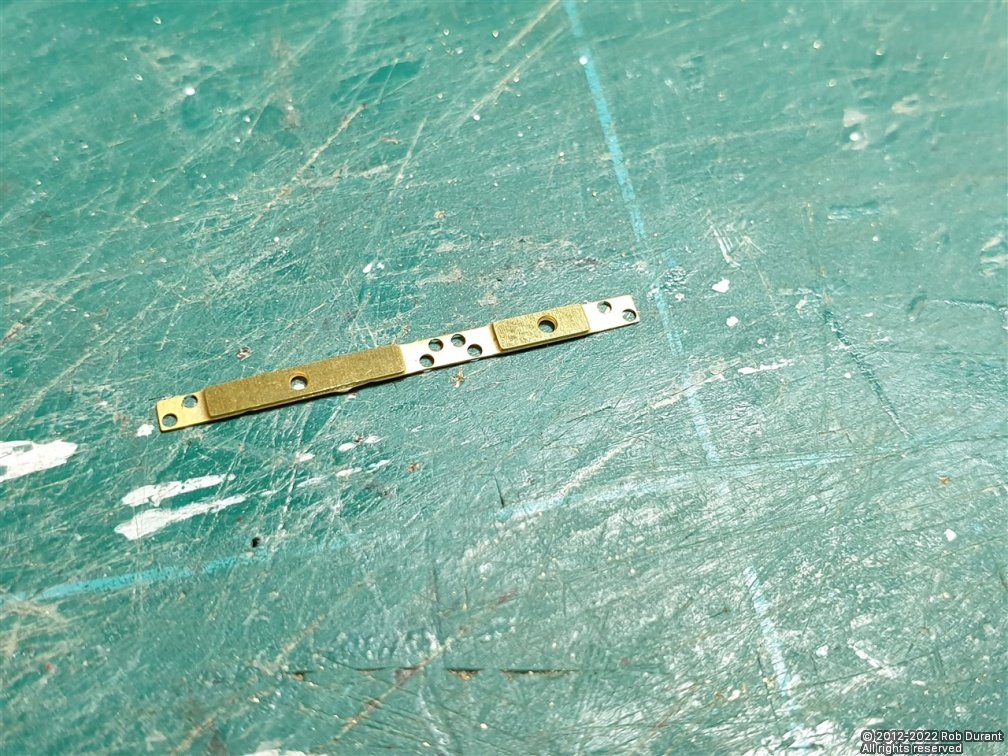
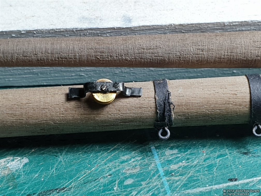
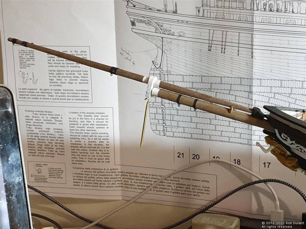
Thanks for the likes. Having worked on the dolphin striker, I added the sheaves, eyelets and bands around the bowsprit and the main topmast, and painted the white sections. The sheaves that mount to the sides of the bowsprit are made from photoetch, and I found this a challenge again. Holes are etched in to allow the structure to be mounted to the bowsprit, but the gap between the holes was so thin that I found it impossible to bend the photo-etch without it bending where the holes were. Instead, I made my own band to go round the sheave. Here is the photoetch part... And here's how it looked after I'd tried to bend it (those who are more au-fait with photo-etch may well see what I'd done wrong here?) And the part I eventually made from copper... And here is the finished bowsprit (with the dolphin striker fitted but only half completed) And the topmast to topgtmast transition now detailed...
-
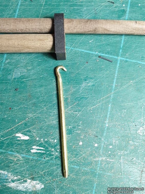
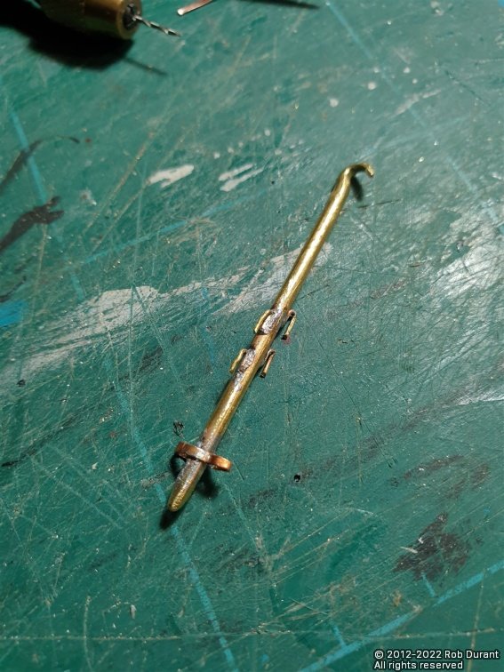
Definitely time for an update... I've got somewhat behind in the updates so it might be a couple of posts. First off was the bowsprit detailing, and in particular the dolphin-striker. This was shaped from 2mm brass wire, tapered at either end, and then bent into a hook shape at the top. Once shaped, fittings needed to be soldered on. Four hooks, two on either side of the striker, act as guides for the various rigging lines that pass by the striker. Then chains attach towards the bottom end of the striker. There is a beautiful, fine piece of photo etch that is supposed to sit on the front of the striker as an attachment point. I tried to use this, but I was clearly too clumsy as it crumbled in my hands before I had the chance to try and fit it to the striker. I struggle to imagine it would have held up to having the chains attached, and almost certainly wouldn't have stood up to my rigging process. Instead, I fashioned a simple strap using copper offcuts from the hull tiling fret) that formed two anchor points, one in front and one behind the striker. It looks appropriate delicate, but is actually quite sturdy, so I feel much more confident this will do the job. More progress has been made, but I'll post another update after dinner Happy building Rob
-
I don't. That would be a question for @MarisStella.hr . I have noticed that in various places on the plans there are detailed sections shown in 1:21, which obviously works better at 1:63 than 1:64, but yes, it doesn't work quite as well for imperial as 1:64 / 1' = 3/16". Thankfully I'm of the generation that was taught both metric and imperial at school in the UK, so neither phase me too much. Thanks Rob, That makes perfect sense. I am enjoying watching your Glory of the Seas come together no end.
-
Quite a shift from Wyoming, but equally fascinating. Thanks for sharing your development steps And amazing to think that (if I'm right) Oregon was launched 10-20 years before Wyoming....
-
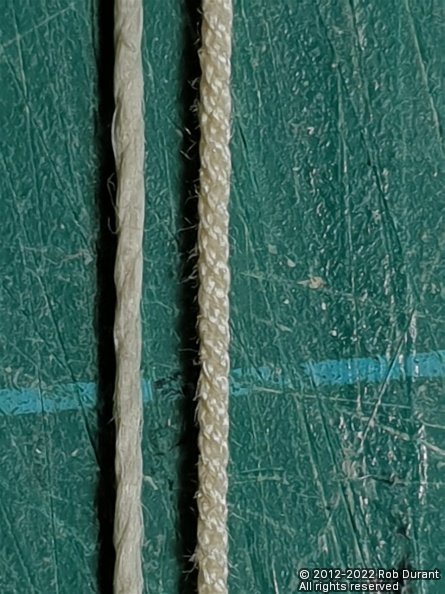
It's pretty quick once you get going... 5 minutes for a 14ft length of rope... and a whole lot cheaper than buying it I just need to master dyeing the darker rope for the standing rigging. Below is a shop bought rope on the left and my rope on the right... I couldn't go back
-
Lovely clean work, George. What a great way of strengthening the spreaders... it would be disheartening to see them bend or break half way through rigging, and this gives a great safeguard.
- 602 replies
-
- 2
-
-
- Flying Fish
- Model Shipways
- (and 2 more)
-
Thanks @gak1965. I enjoy the rigging, so it's nice to be getting closer to that stage. There'll be a lot of rope making ahead!
-
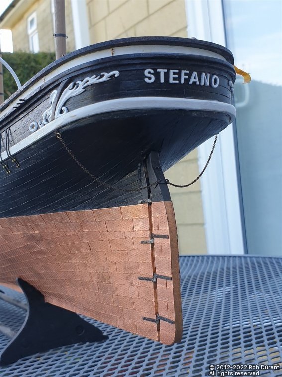
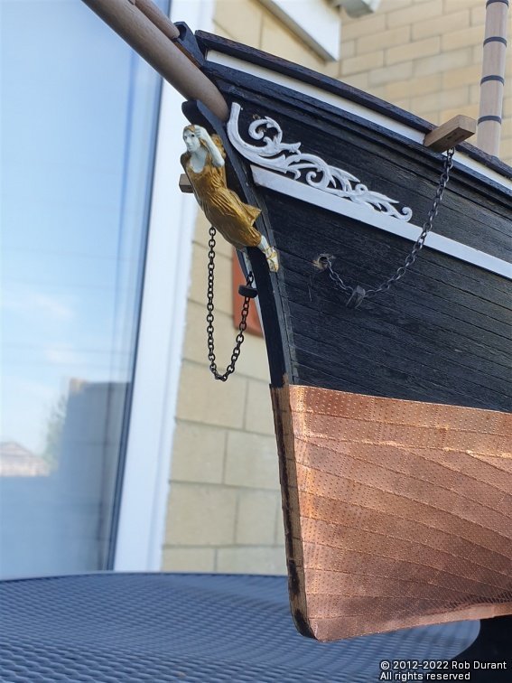
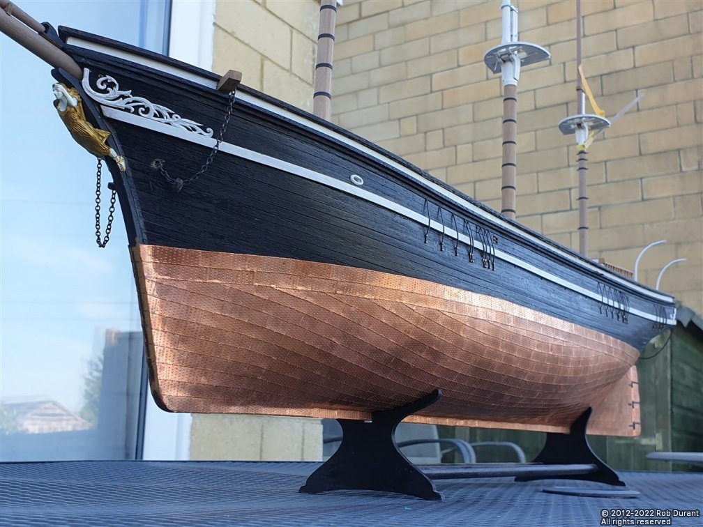
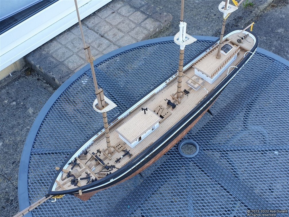
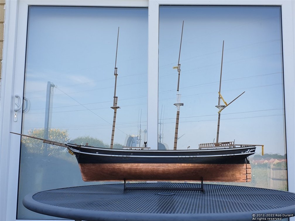
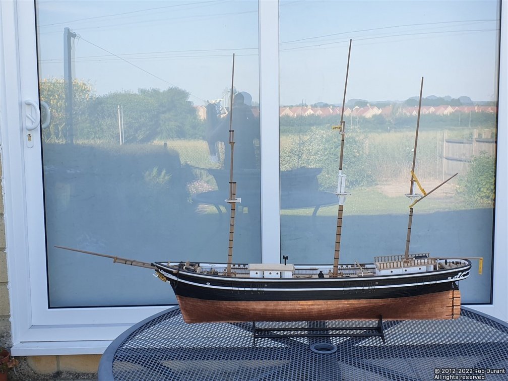
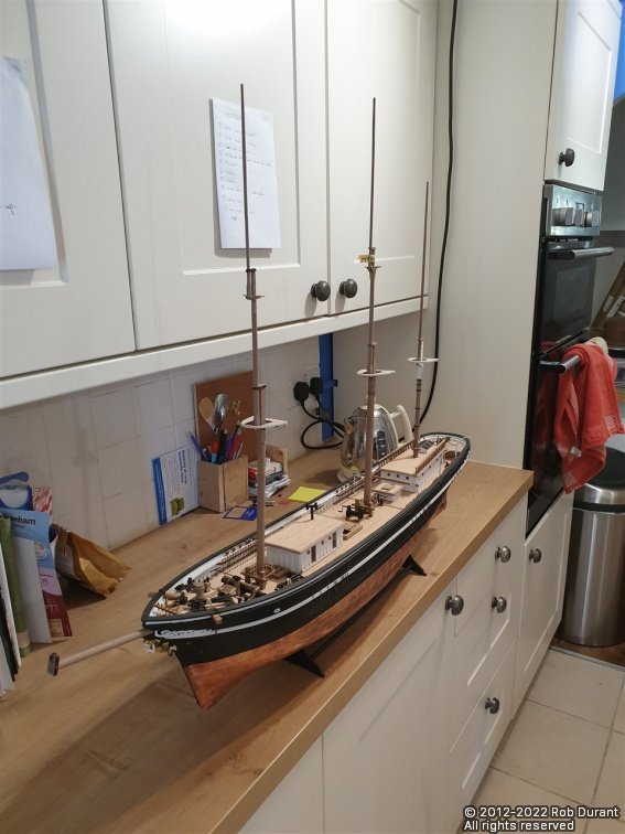
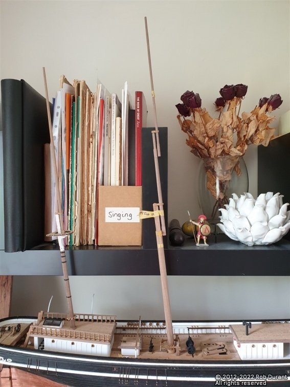
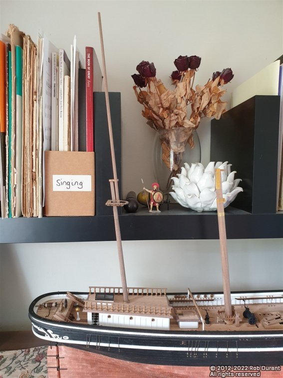
Thank you @rwiederrich. Yes, I have to do a walk into the kitchen to turn the boat these days... Ethalion is still sat at the other end of the bench, so not enough room to slide Stefano round the corner to see the other side these days... While the weather is so exceptionally fine, it seemed like a good moment to take some photos of the whole... Bearing in mind that so much of it is only placed in place at the moment, Stefano's not looking too shabby At some point, I shall try and get some reasonable photos of Ethalion and Stefano side by side - that really would be a fascinating comparison, but Ethalion is protected behind dust covers at the moment, so it will have to wait.
- 286 replies
-
- 18
-
-

-
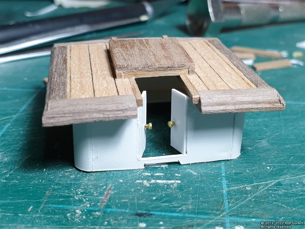
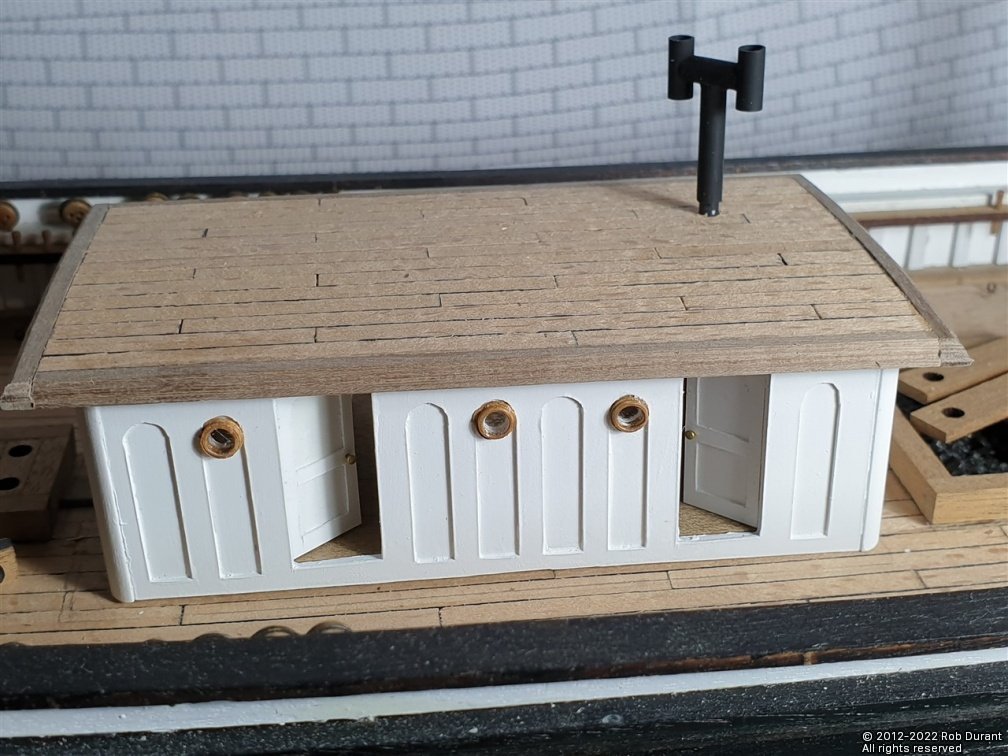
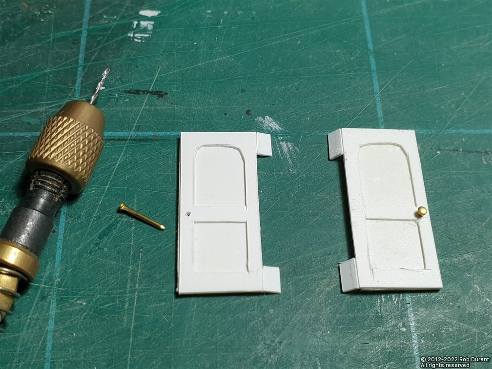
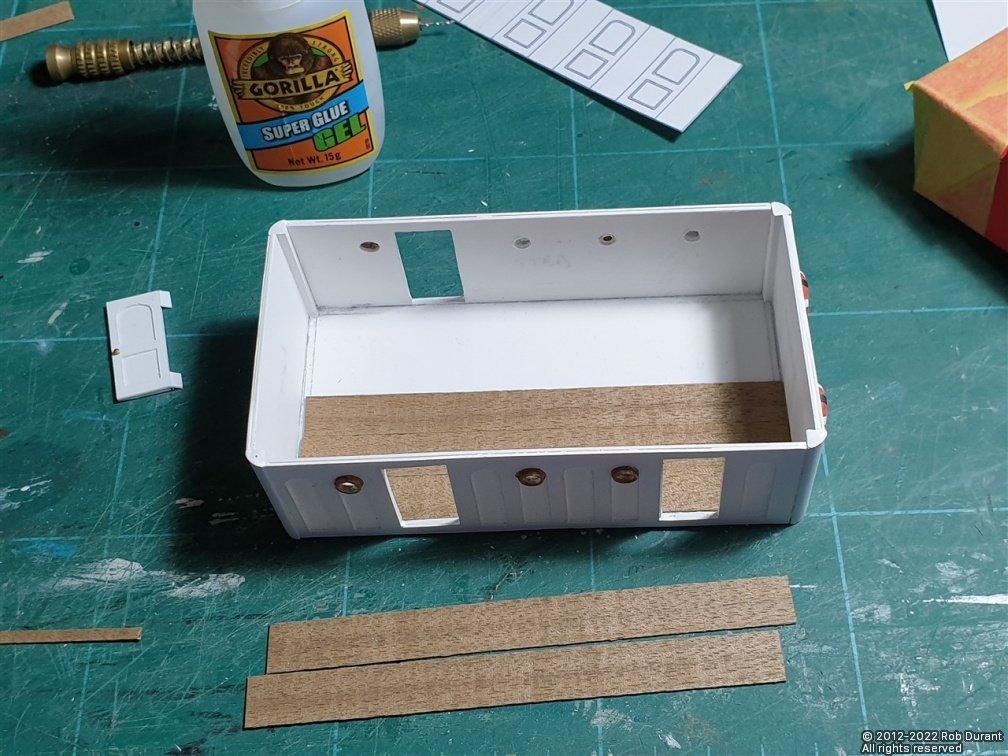
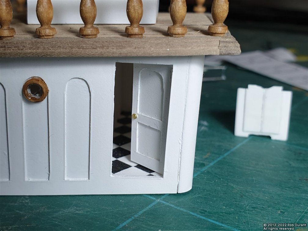
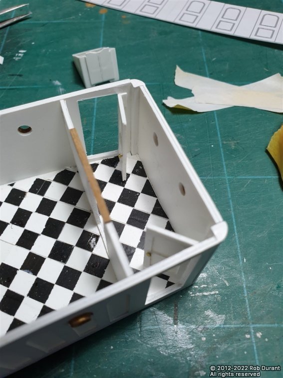
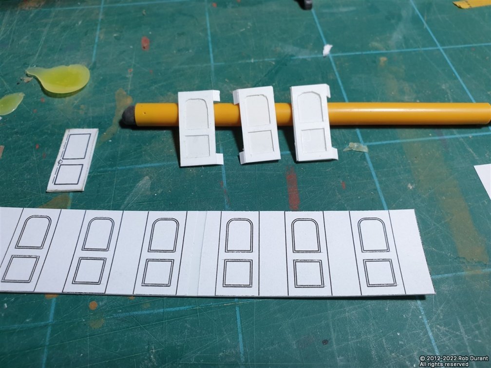
Hi all, Thanks, as always, for the likes I finally worked out how I wanted to do the doors for the superstructures and the companions, so those are done. They're made out of two layers of styrene with tabs left on to attach them to the cabin walls. Caldercraft nails were used for the door knobs... Before I could put the doors into the fore cabin, it needed a floor, which was made of 0.5x10mm walnut... Then doors were added to the main companionway. Next, I turned my attention back to the masts, and simulated the sheaves in the maintop mast. I added the iron banding round the main mast cap, and the eyelets. I added the fid using brass wire (cleverly the location of this is laser-etched into the fore and aft beams of the cross trees. And then the whole was given a couple of coats of paint. Finally, I turned the jib-boom, and added the block and seat. I've added a short length of brass wire into back of the jib boom that goes into the block at the back to add strength. I know I'm going to knock it at some point, and I want to give it a good chance of withstanding my clumsiness as and when that happens. The seat that sits between the bowsprit and jib boom needs sanding, but it was quite fragile, so I wanted to glue it in place on the bowsprit before sanding it to add strength. That's it for today Happy building Rob
- 286 replies
-
- 12
-
-
-
Hi all, Thank you for all the likes, and for your kind words @rwiederrich. I have completed turning the masts, topmasts, and topgallant masts now, and begun detailing them. The cross trees have been made up for the fore and main masts, and so the top gallant masts are now stepped (albeit this is all dry fitted at the moment.) The mast bands are added using black card. I've also started to turn spars with the mizzen gaff and boom. That's it for now
- 286 replies
-
- 13
-
-
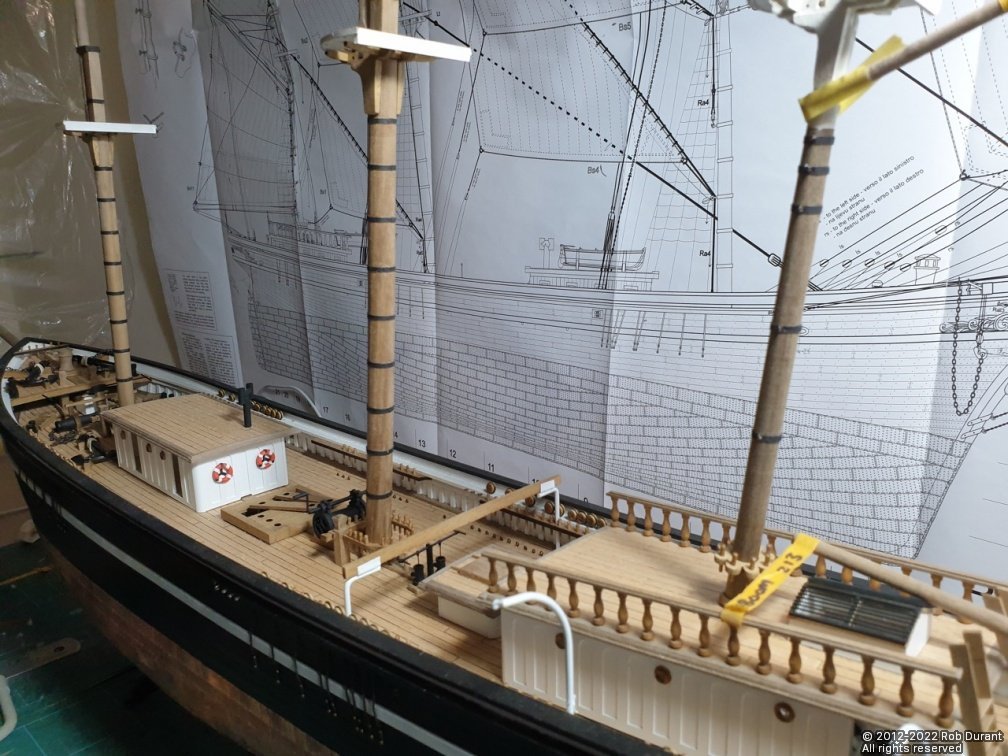
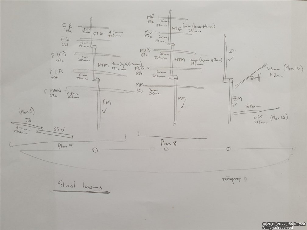
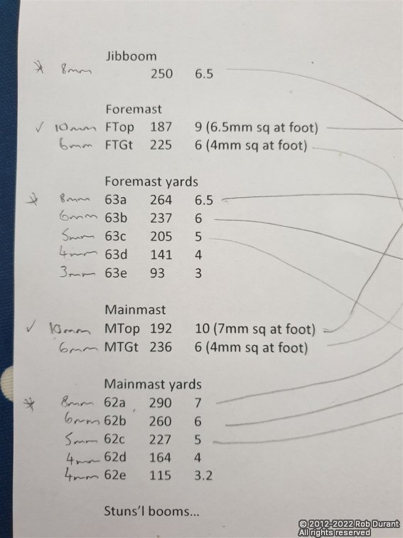
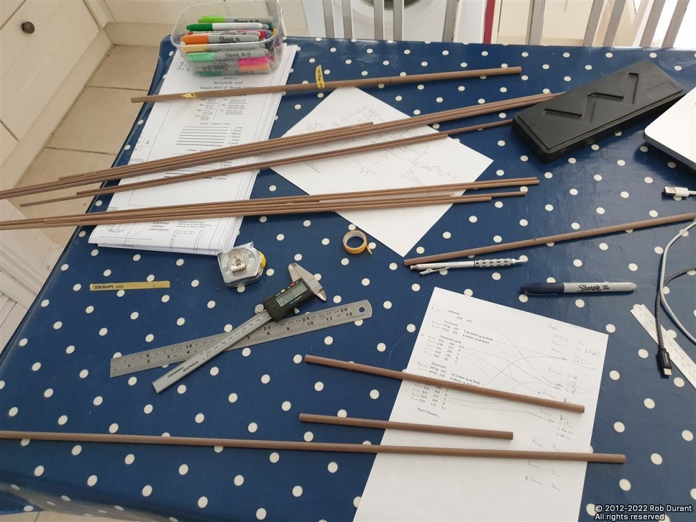
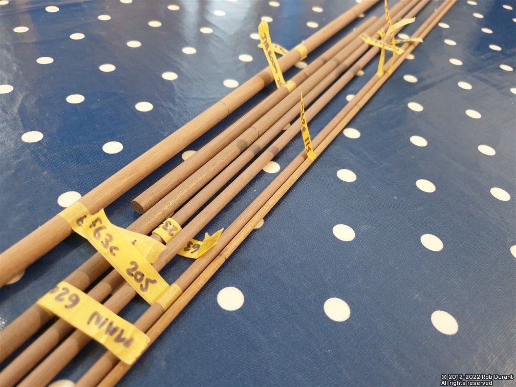
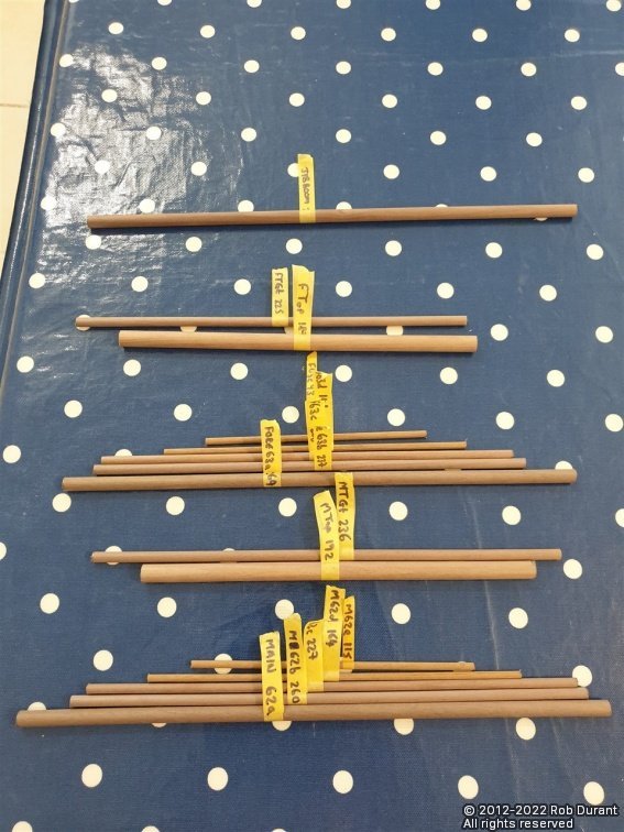
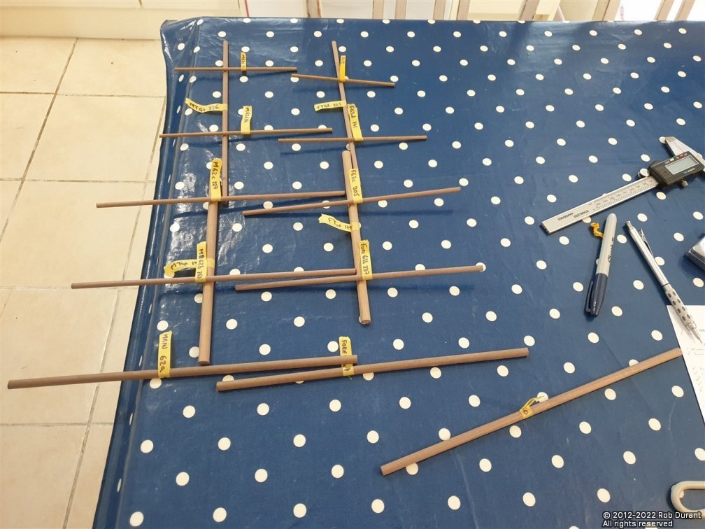
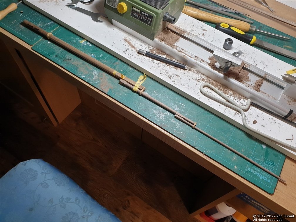
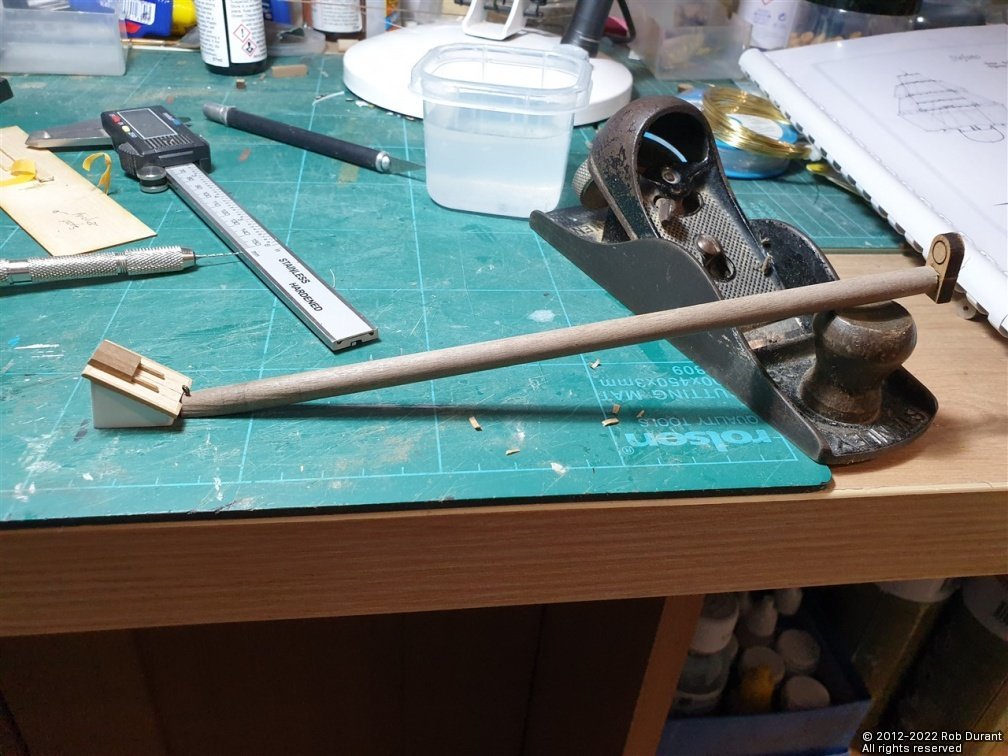
Hi all, I've been working out what dowels I needed to make the masts, yards, bowsprit, gaff and boom... These were calculated based on the largest diameter required to allow the square sections to be made as part of the mast. The first step was to work out which dimensions were shown on which plans. The answer being: plan 10 for the mizzen mast and spars; plan 9 for the foremast and yards and jib boom / bowsprit; plan 8 for the main mast. (excuse the messy drawing below, but it helped me think it through in one go, and meant I had all the measurements in one place) Having done that, the next task was to take stock of what dowel I had, and what I needed, and then assign the spars to the stock. The measurements are my own taken off the plans, so don't take my word for it - do your own measuring - you have been warned! The left hand column (e.g. 8mm) is the dowel diameter I intend to use, the next column is my code for that particular mast / yard, the third is the length of the spar, and the fourth is the diameter at it's maximum (where a square section is required, I've noted the maximum diameter to encompass that, along with the final size of the square section) - nb: I've noticed now, that some of the square sections at the foots of the top masts are NOT square... they're rectangle, so watch out for that, too. The pencil lines go from the spars to the stock I have... this is my way of checking I'm not going to run out, but also that I'm using the wood in the most efficient way. The spars are measured out onto the dowel with at least two centimetres spare, so that I have a bit of surplus to be left at each end while turning the spars. The measurements on the table above do NOT include this surplus - I just add it on as I mark up the wood. Everything's marked out onto the dowel, with masking tape tags to keep a record of which section will be for which spar... Once that's done, I cut the lengths out, ready to be turned. Laying them out gives some idea of what the effect will be (and helps you spot if you've missed any... as I had... I missed the mizzen gaff and boom! Then it was on with the turning. Today was the turn of the main topmast and topgallant. These were turned, taking care to fit them to the caps as I went. And it's always pleasing to be able to raise the mast with no glue required at all... just the friction of the cap holding it all together. I'm beginning to get that dread sense of the scale of this model when she's complete... and that's before I begin to think about the stunsails! Thanks as always for all the likes Rob
- 286 replies
-
- 12
-
-
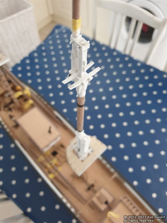
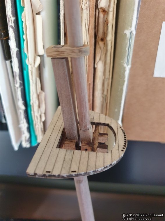
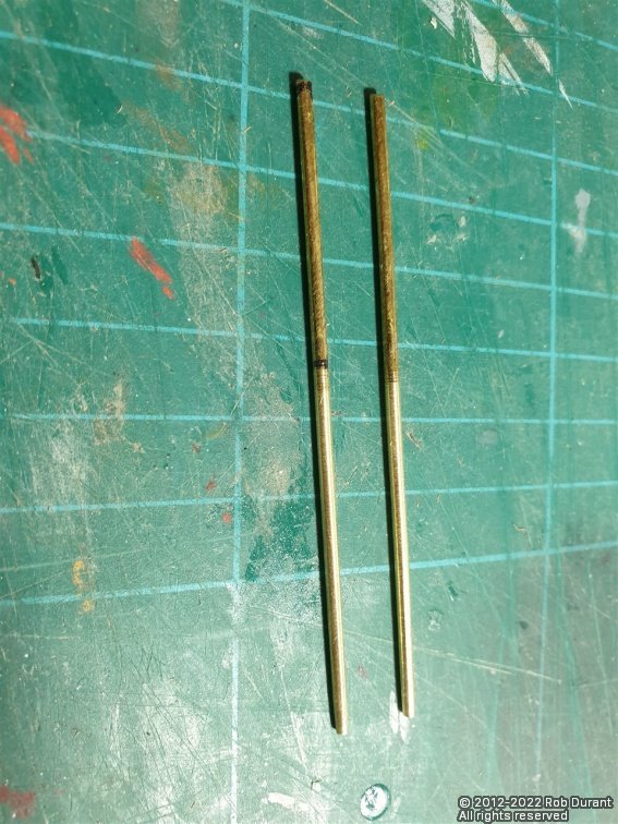
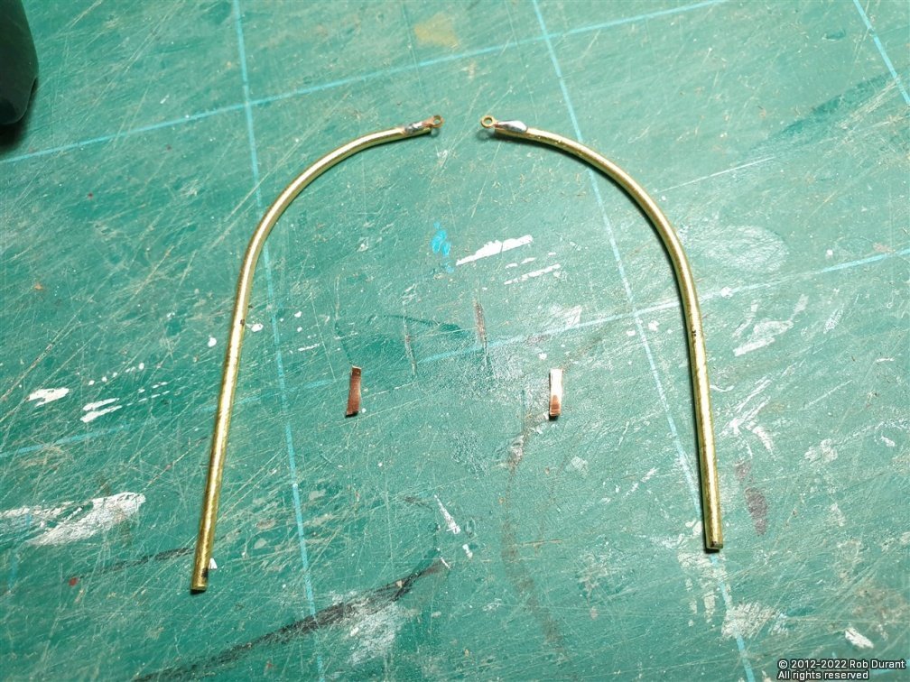
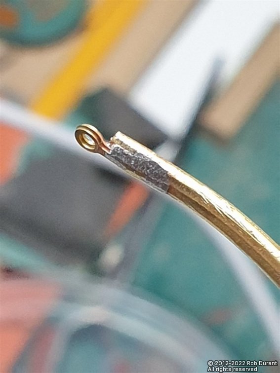
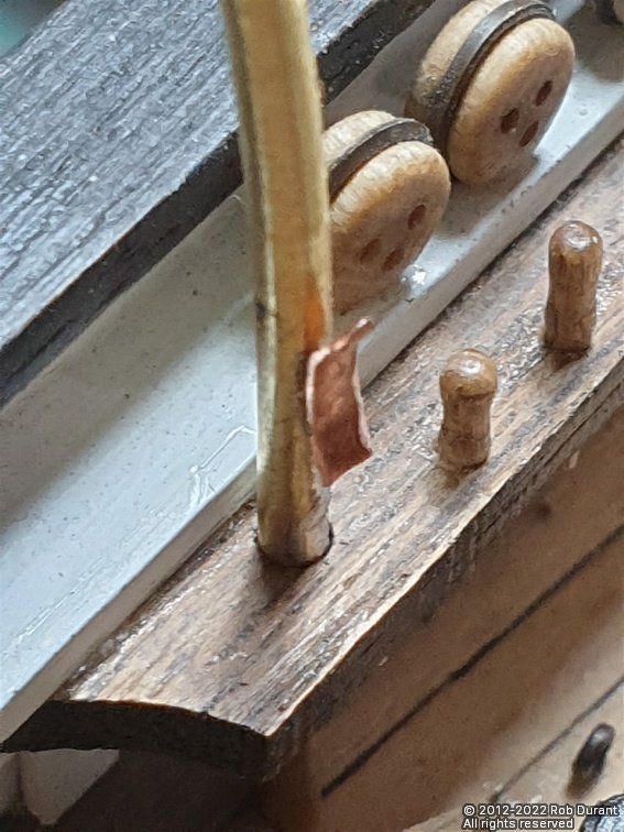
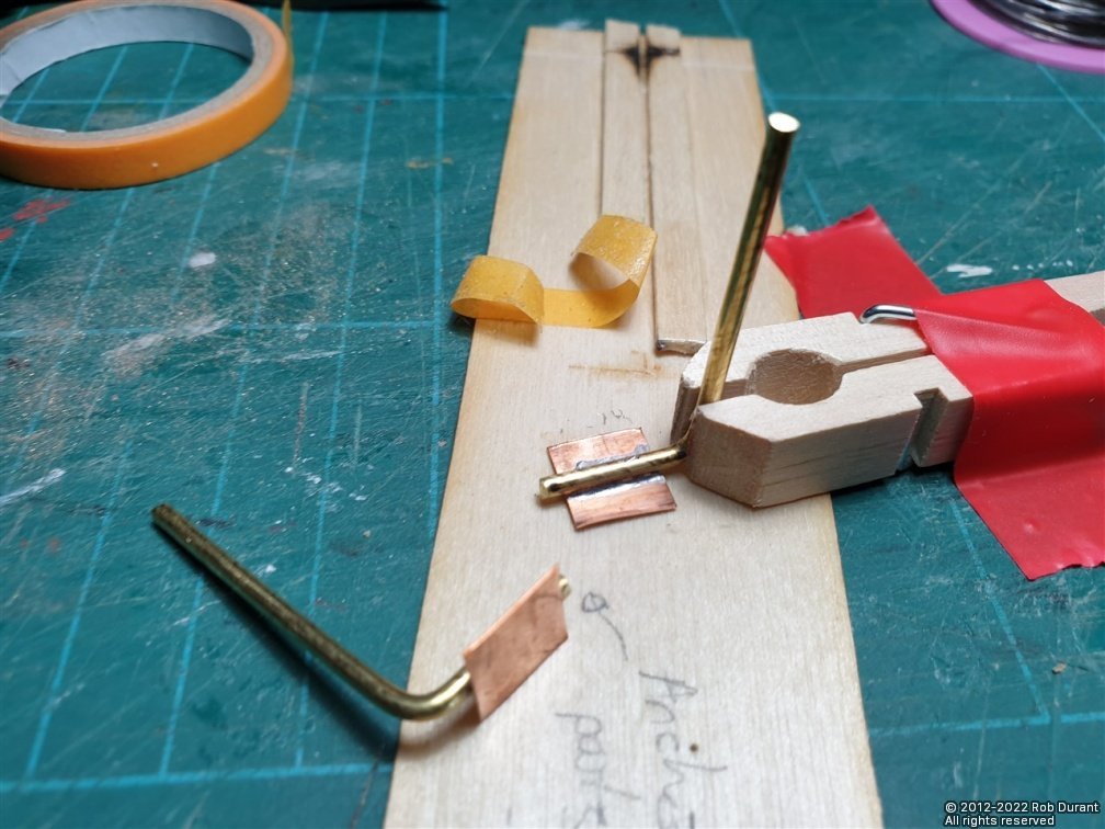
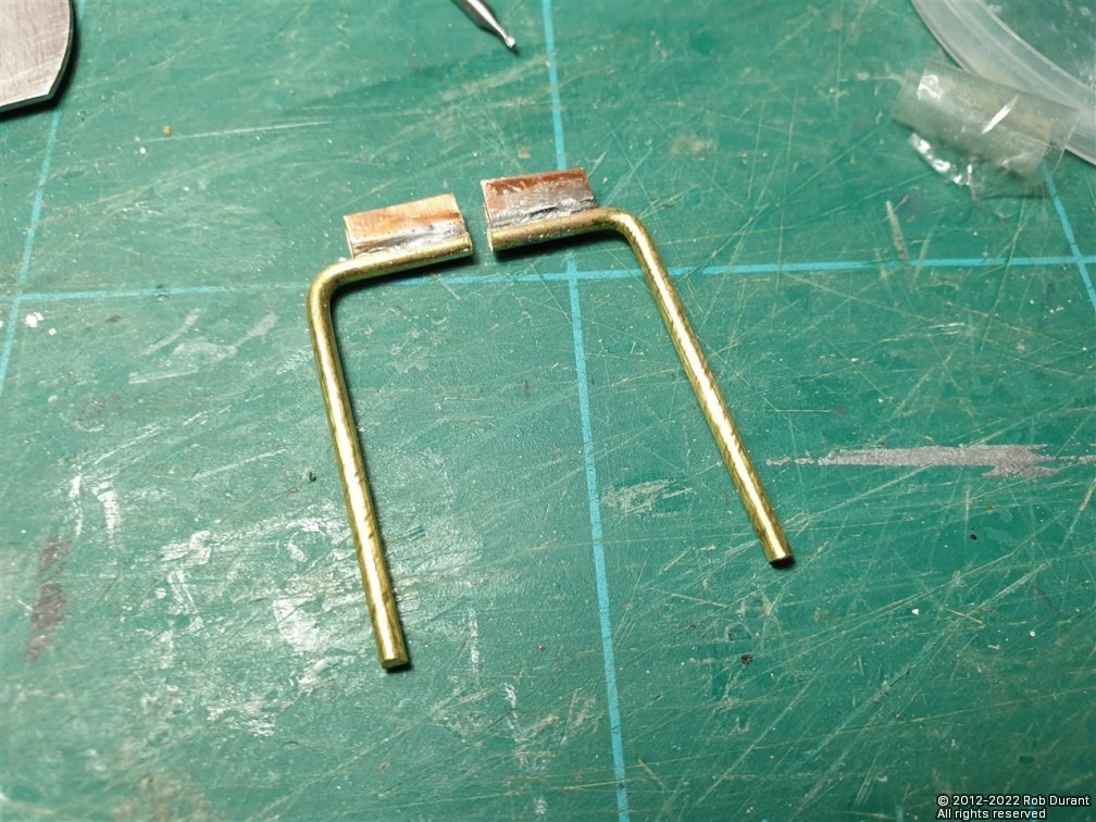
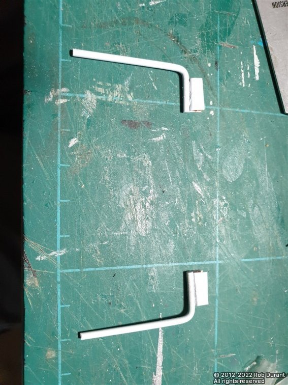
And the second part of the update.... I've also spent some time putting together the mizzen top, and making and fitting the mizzen topmast. There's still a lot to do on both... The mizzen top is made from laser cut parts from both the ply, and the 2mm and 3mm walnut sheets. This structure will have a walnut surround. I turned the walnut topmast, and fitted it to the cap. The mizzen mast needed a little fettling to fit the structure that supports the top. Today I added the cheeks to the mizzen, and the pin rail that sits just above the deck. I'll show that in a future photo, as I'm waiting for more belaying pins to arrive (I'm replacing the kit ones with Caldercraft 9x1.5mm belaying pins) Finally, I turned some 2mm brass rod from the kit to taper it and then bent it to shape for the ship's boat davits that sit on the port quarter. These had eyelets cut off the top of 1:48 RN stanchions soldered to the top, and copper strip soldered to the back as a cleat. The tapered rod... (It's worth noting that once these were made, I realised that the sternmost davit is shorter than the foremost one - thankfully every other detail is identical, and I'd made these to the longer version, so it was just a case of shortening the sternmost one. As per the cross-support for the boats over the deck, these were inserted into the pre-laser-cut 2mm holes in the pin rails. Next will be to give them a lick of paint, and then it will be back to the mast fabrication. That's it for today. Rob
-
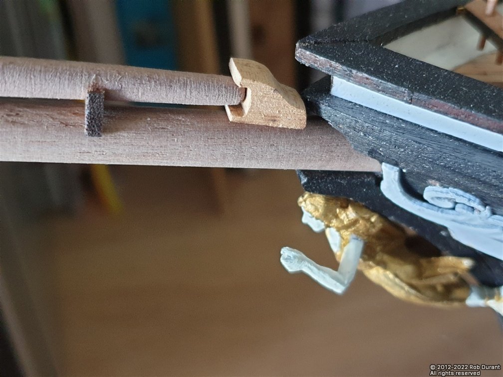
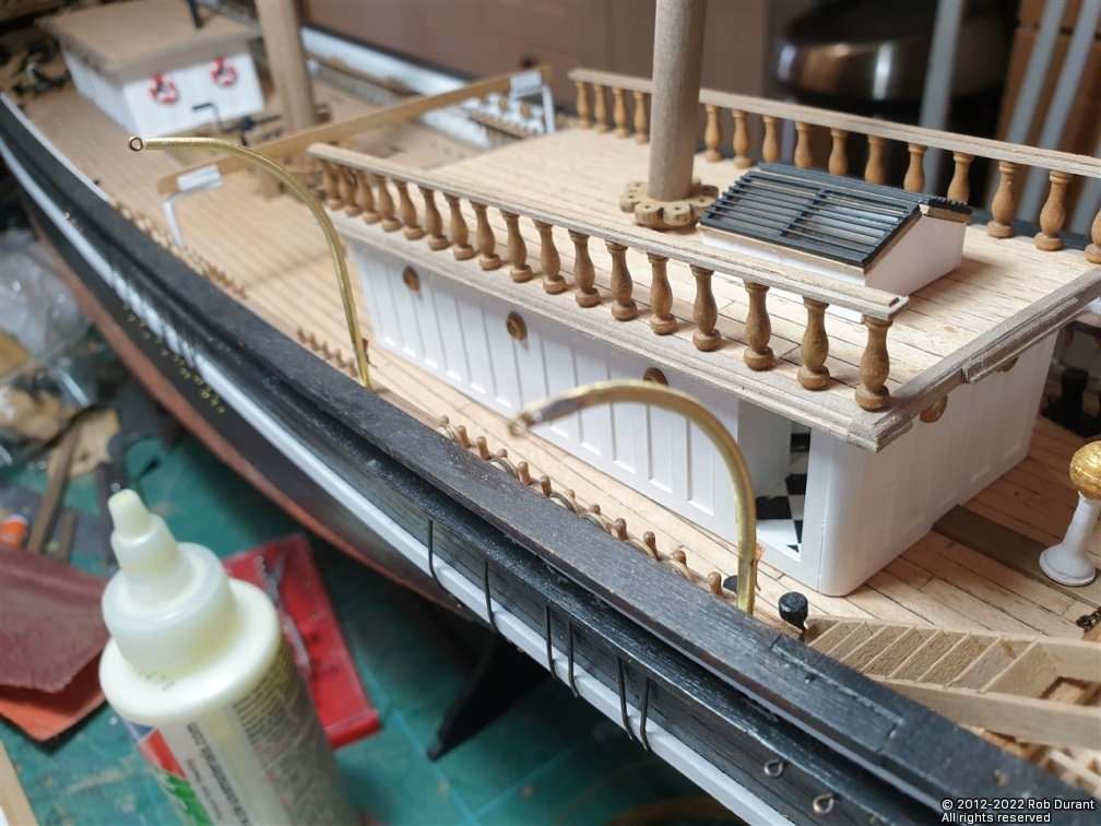
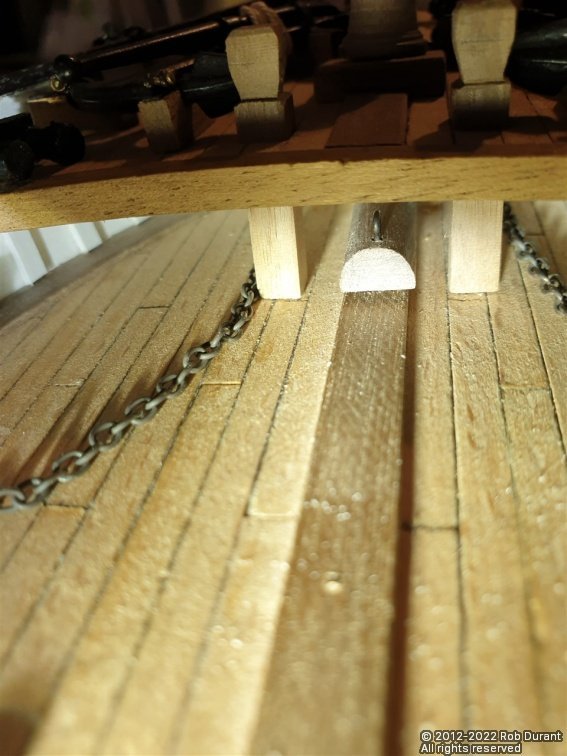
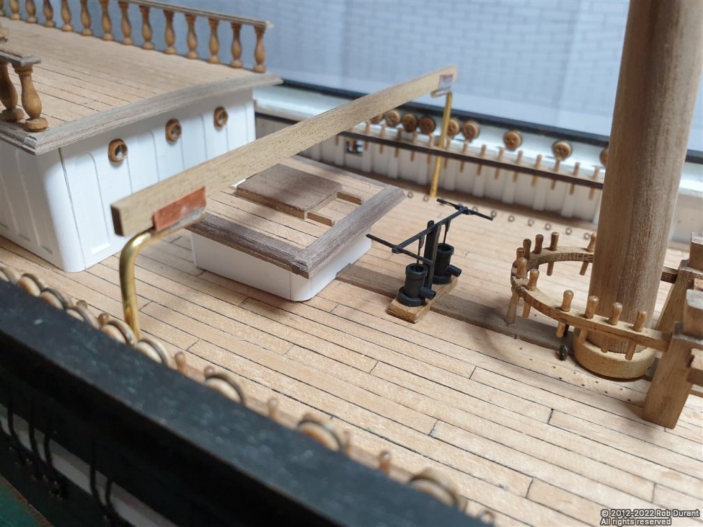
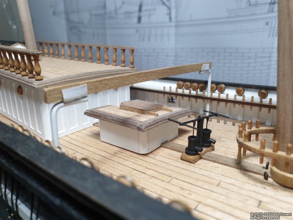
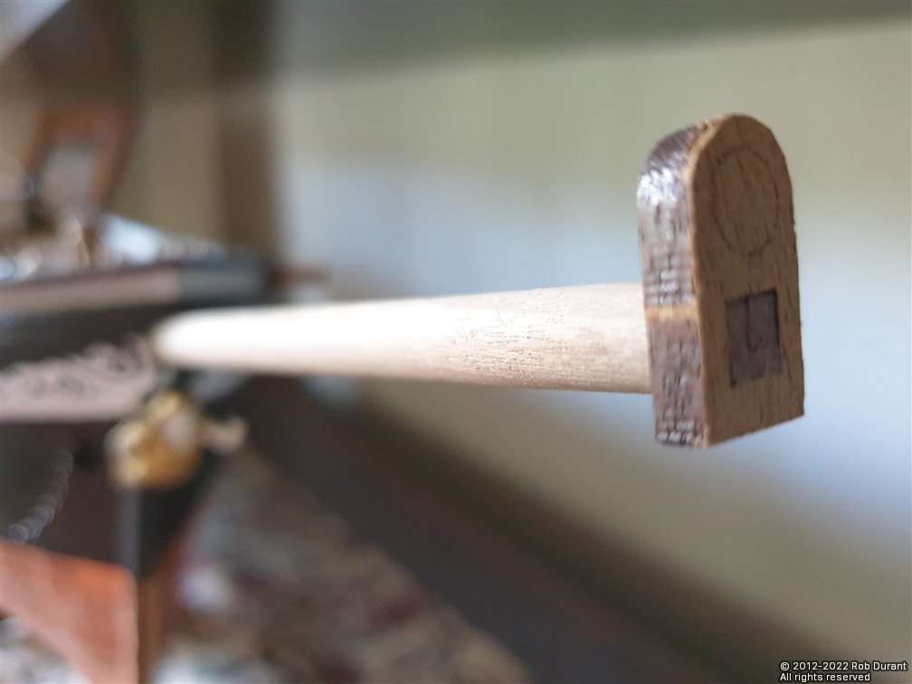
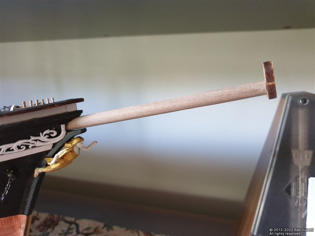
Hi all, Thanks so much for the likes - it's a great encouragement. Part two of the knock-on effect of sticking down the foredeck too early was pointed out in the instructions. They say quite clearly that you mustn't forget the large eyelet under the foredeck. From what I can tell that eyelet only shows up on one side-view on the plans - It sits a centimetre under the foredeck, and needs a hole drilling vertically into the deck. I'd missed it because it doesn't show up on the top down view where all of the other eyelets in the deck are marked. It's kind of important, because it forms the anchor point for the main stay for the main mast! I scratched my head for a bit and realised that I could kill two birds with one stone. By allowing the bowsprit to come further aft, as I had done, the bowsprit would occupy the space where the stay would be anchored. By drilling the vertical hold into the end of the bowsprit, I could then put the bowsprit in, then, once it's finally in place, and I'm rigging, install the eyelet in the end of it (because the hole was now in the right place). This is all hidden behind the companion way that sits directly behind it under the foredeck. The eyelet is installed in these photos, but not glued in place, because the bowsprit will doubtless be in and out of the boat a few times yet. And here's a shot of where the bowsprit ends up when installed. Feeling pleased with myself I went on to install the eyelets on the outside of the hull, and the rails. I also drilled the holes for the cleats at the stern. Nothing much exciting, except that I was tired and broken a few drills in the process. It's a bear to drill down into the upright between the main and topgallant rails. The big eyelets were installed at the bases of both masts. Definitely not a job you'd want to do with the pin rails in place, so do follow the sequence in the instructions here. (I've intentionally not glued down any of the fittings until I'm confident all of these gotchas are finally out of the way!, but the instructions are proving to be in a helpful order.) The next job was to start making the ship's boat cranes. There are two types. A support that runs across the deck, which was made out of wire, and copper left from a fret from the copper tiles for the hull. Hopefully the sequence of photos will be fairly self-explanatory here... The uprights fit into holes that came ready laser cut in the pin rails (which were opened out to 2mm with a pin drill.) I have a little more to share, but I'll put up an extra post after tea, which is smelling lovely! Pork and apple cider casserole. Happy building to you all. Rob
-
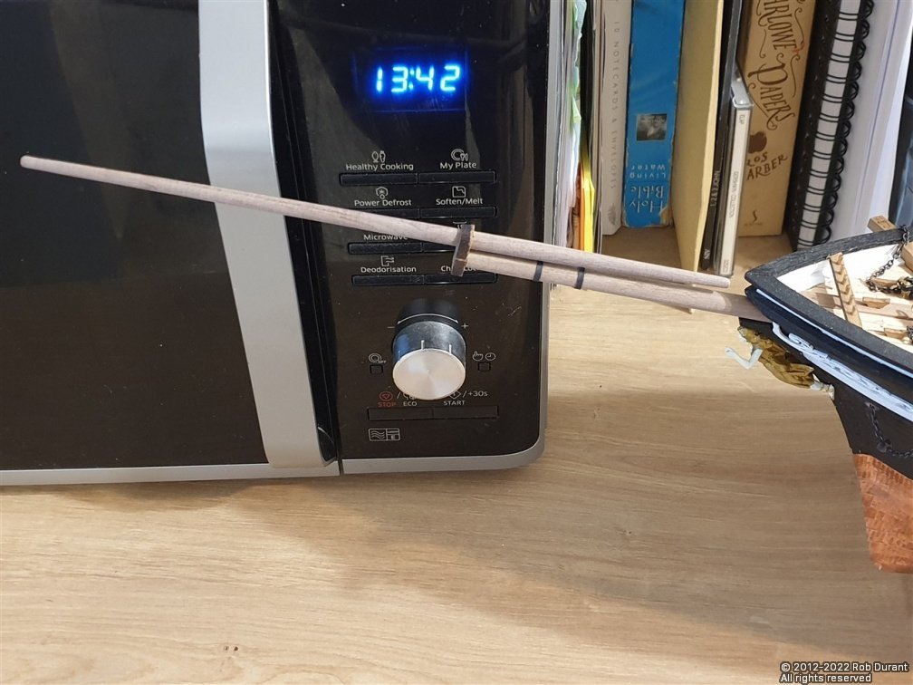
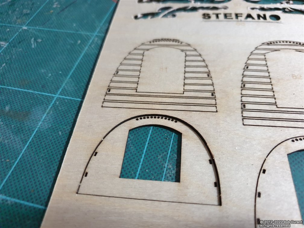
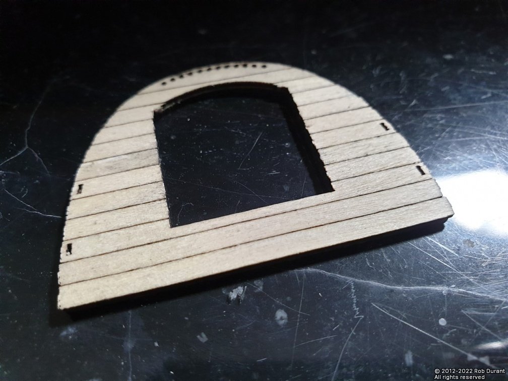
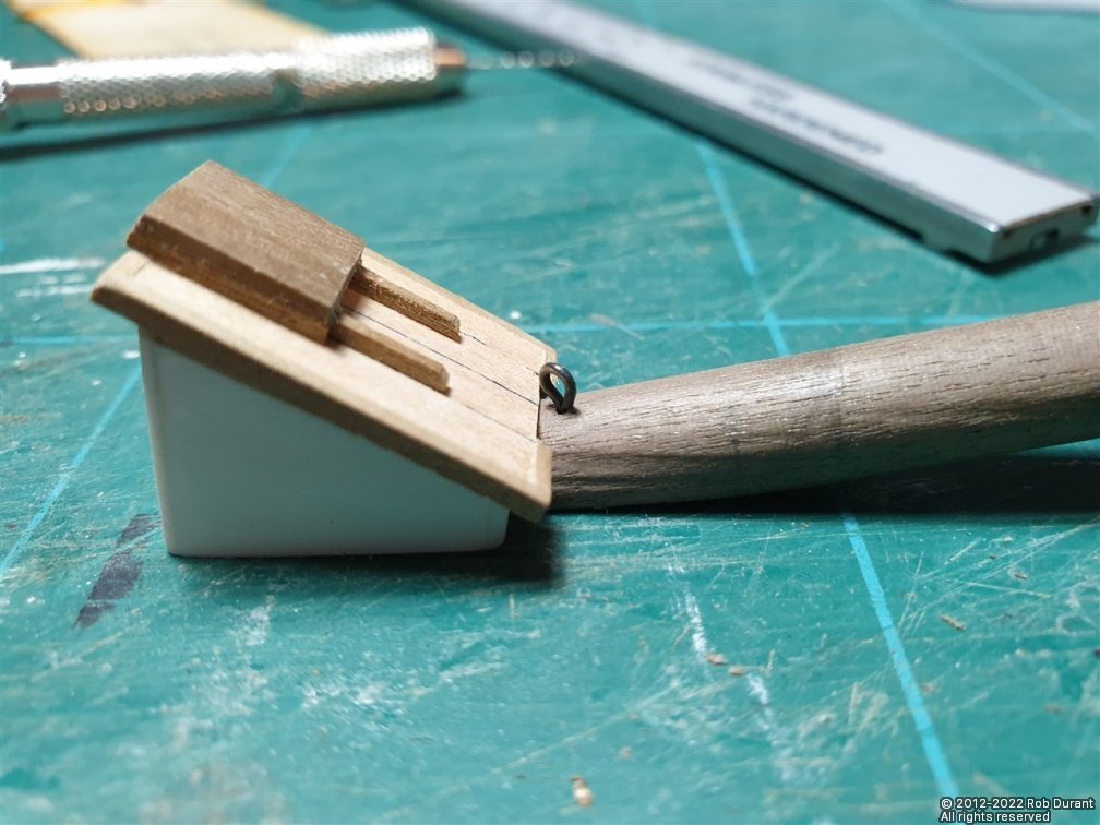
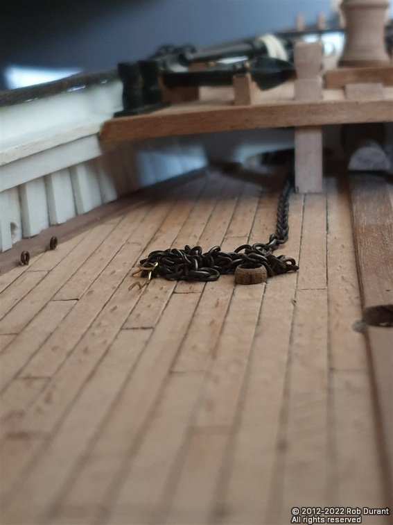
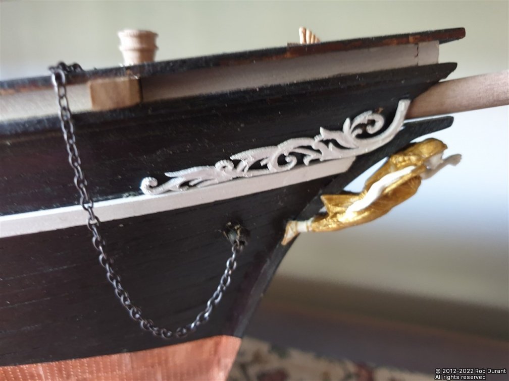
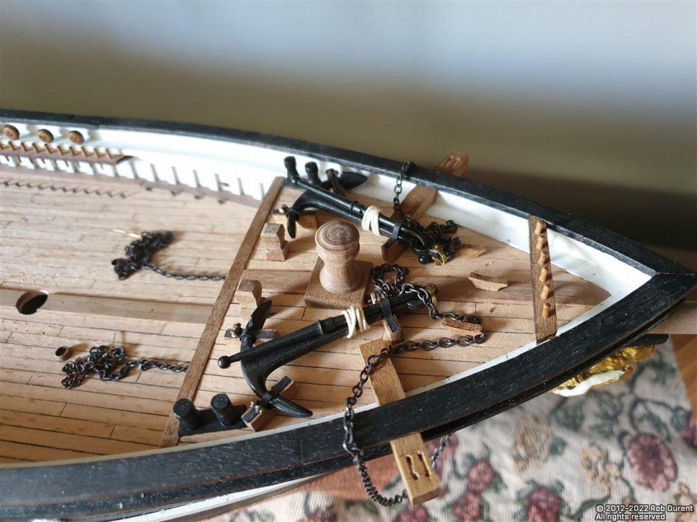
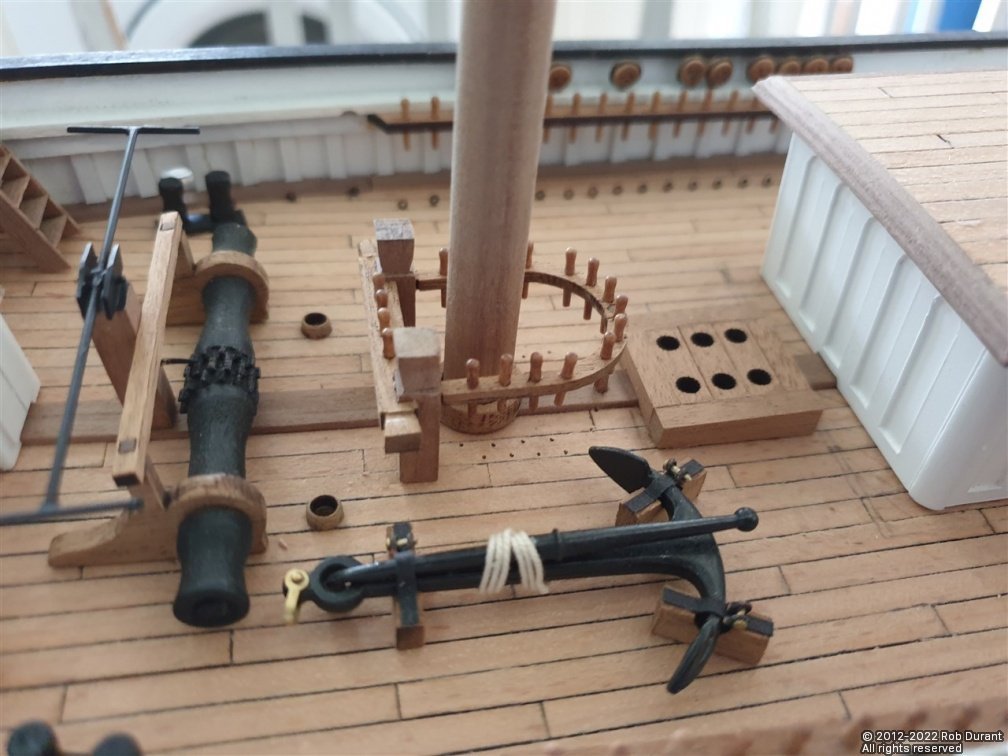
I wanted to see how easy it was to run the anchor chain, having mistakenly glued the foredeck in place too early. Hopefully my mistake will help someone else to avoid it. The answer is that using brass wire and a torch and some needle nose pliers, and lots of patience, it wasn't too bad. Mainly because I'd hollowed the balsa out before putting the deck on. With that said, it was still something of a fiddle, and once the brass wire was threaded through from one side to the other, I could then pull the ready-blackened anchor chain through. It will come from the holes in the deck just aft of the windlass, pass round the windlass, then go through the bulkhead, down to the hawse pipe holes, out of the bow, loop up to the cathead, where it is wrapped around to find the anchors on the deck. I realised in doing this, that the chain was too big for the hawse hole, so I opened them up and had another go. (All of the deck furniture was removed for this task, so that I had access, as you will see in the photos...) The ends are left completely loose, as are the rosettes on the hull, as these will be stuck back on once I've finished getting everything finalised. The other thing I've started working on is the bowsprit. By the plans this is made from 10mm walnut, but my hull has ended up fitting an 8mm dowel. It needs shaping so that it reduces to 7.5mm at the outer end. On the plans, it almost seems to be greater in diameter at the stern end, than at the point where it goes into the hull, but that would mean that either the hole would be too small so that it could be inserted, or once inserted, the hole at the entry point at the bow would be too large. I've opted to keep it at 8mm all along the length once it enters the hull. According to the plans the jib simply ends at its stern end, hanging in thin air, shortly after it exits the sternmost bulkhead it passes through, but again this provides no force pushing forward to counteract the pressures of the rigging on it (or indeed, my whacking it as I walk round the house with it, moving it from my boat building space to its home on top of the piano! So, I've left it slightly long, and bevelled the bottom edge, so that it now pushes right through until it gently sits on top of the king plank. As it stands, it needs shortening about 7mm, which will be taken off the stern end, as the square section has been cut in at the bow-end. It needs to be a 4.7mm square section to fit the bowsprit cap. This proved simple enough to do, and I filed in this section while it was still in the lathe, which helps me to line it up for the filing. As you'll see, I haven't removed the laser char from the outside of the bowsprit cap, as I wanted to leave it as strong as possible while the test fitting was taking place. The laser-cutting on these 4mm parts does not go quite all the way through the part, so a little cutting out is required, but not too much. It's certainly easier than cutting out parts with no help at all. That's it for now. I really enjoy this stage of a build. It feels like it's all coming together quite pleasingly! Happy building to you all.
- 286 replies
-
- 11
-
-
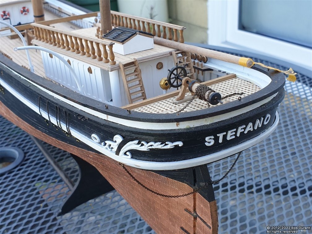
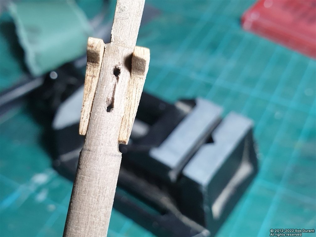
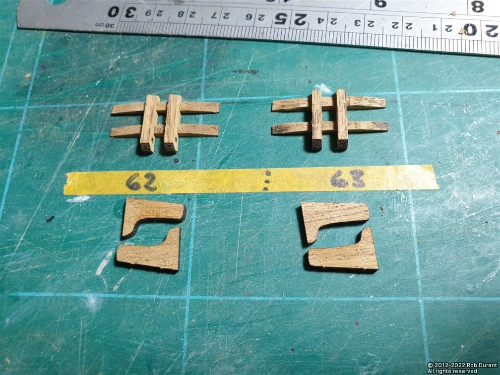
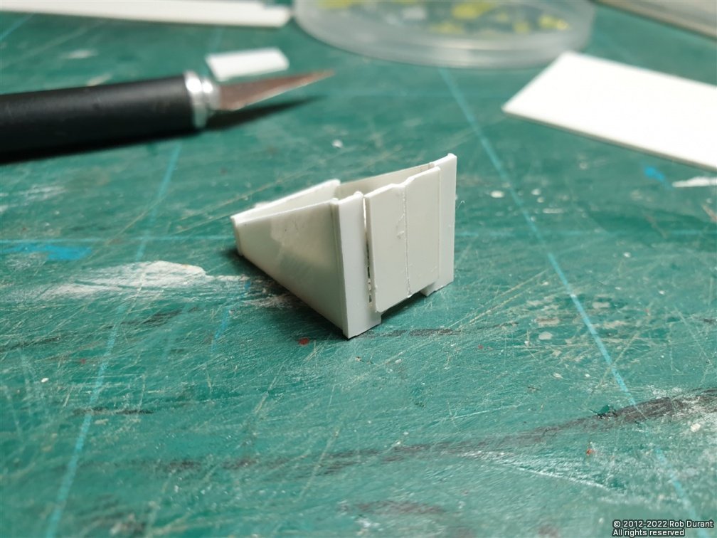
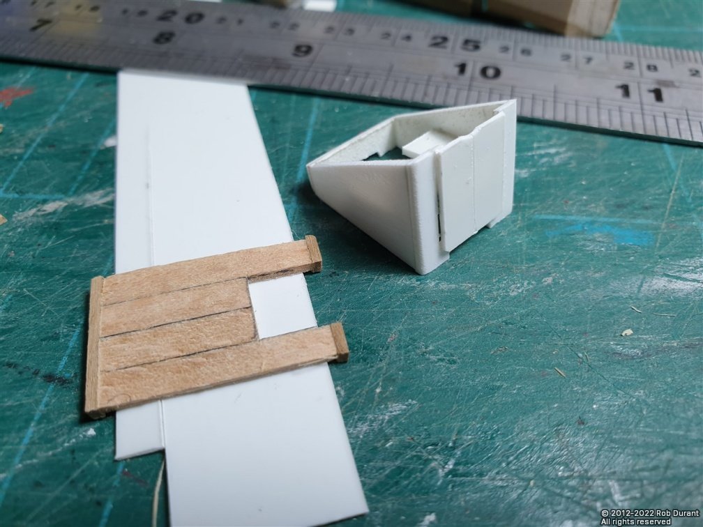
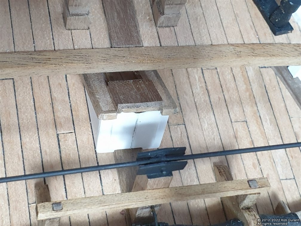
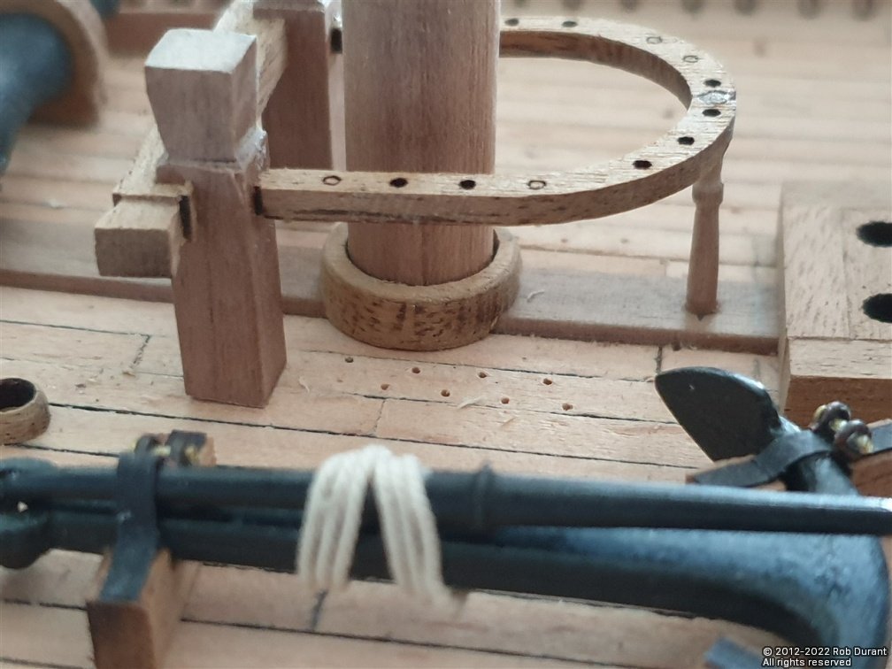
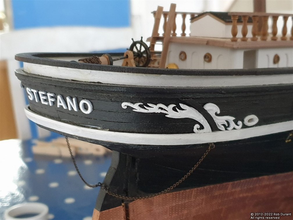
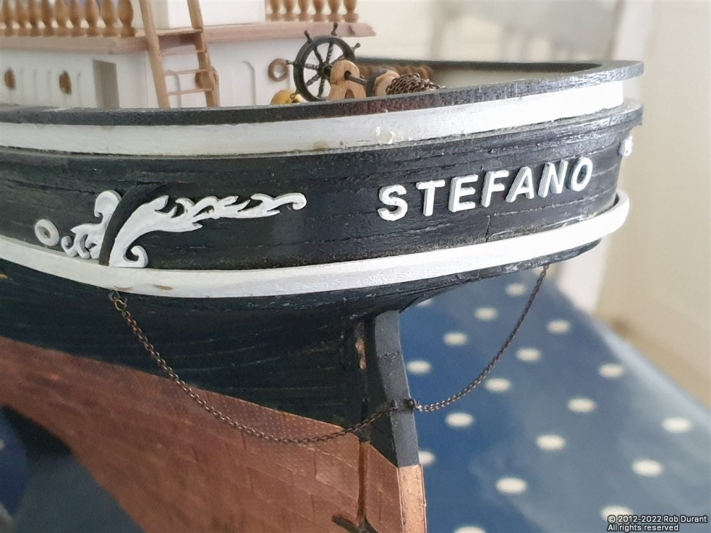
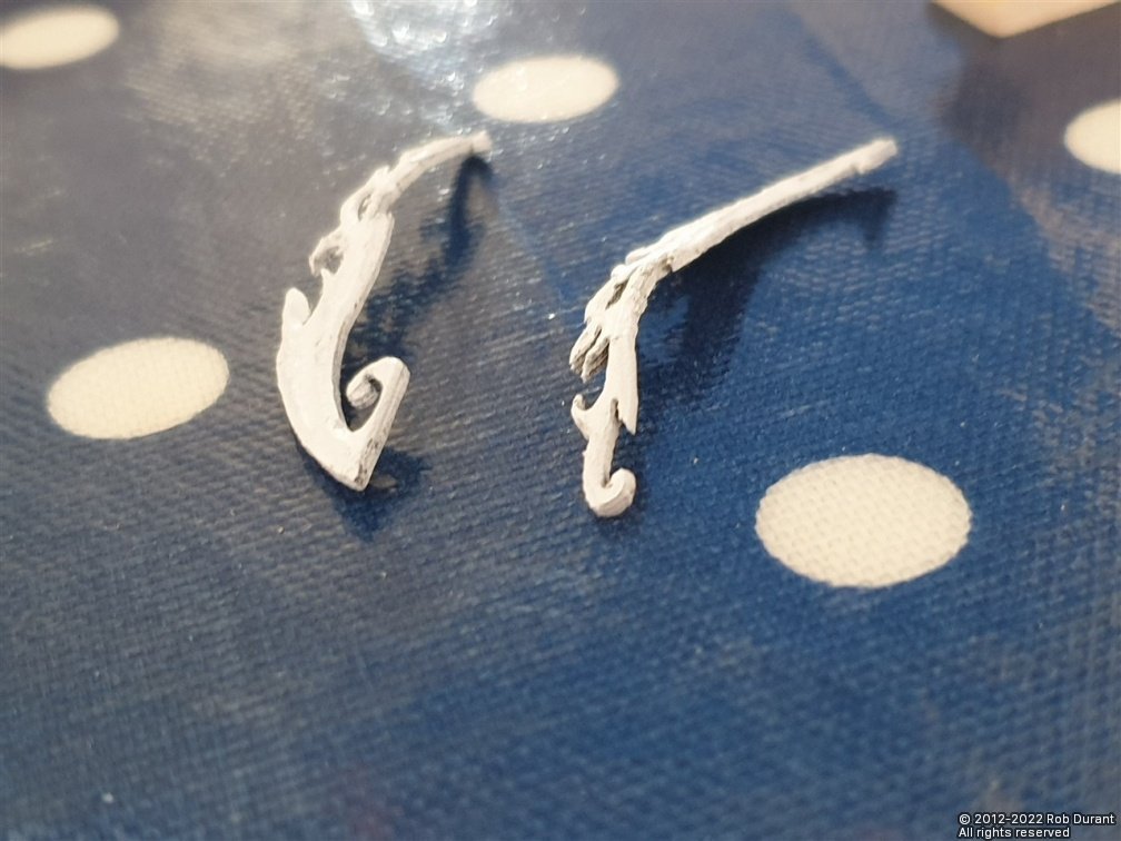
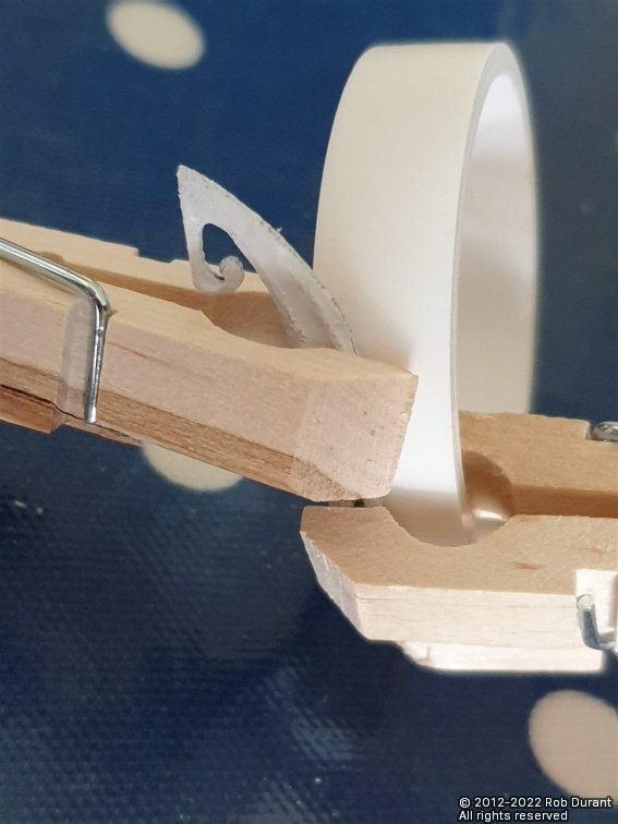
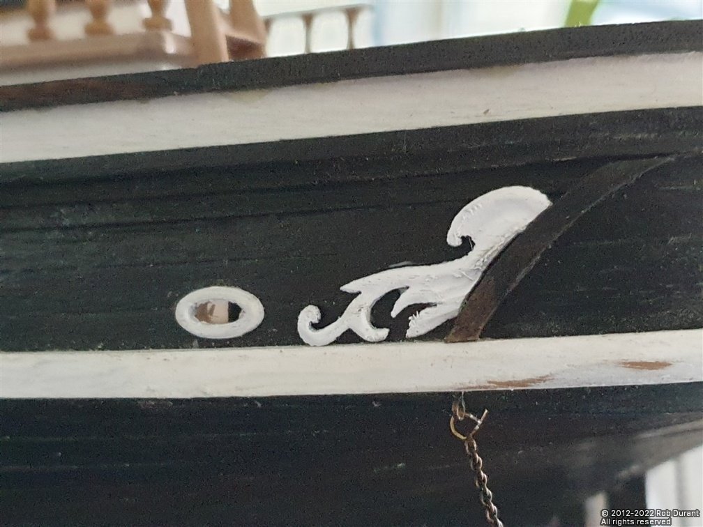
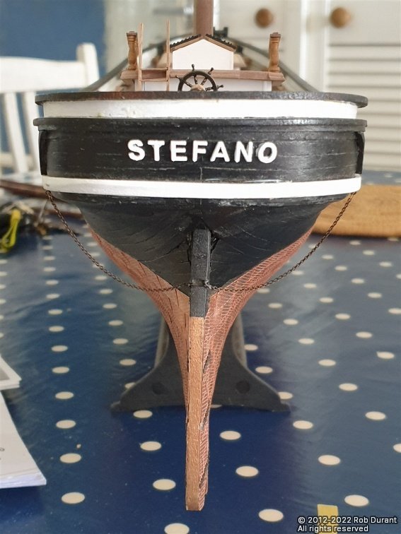
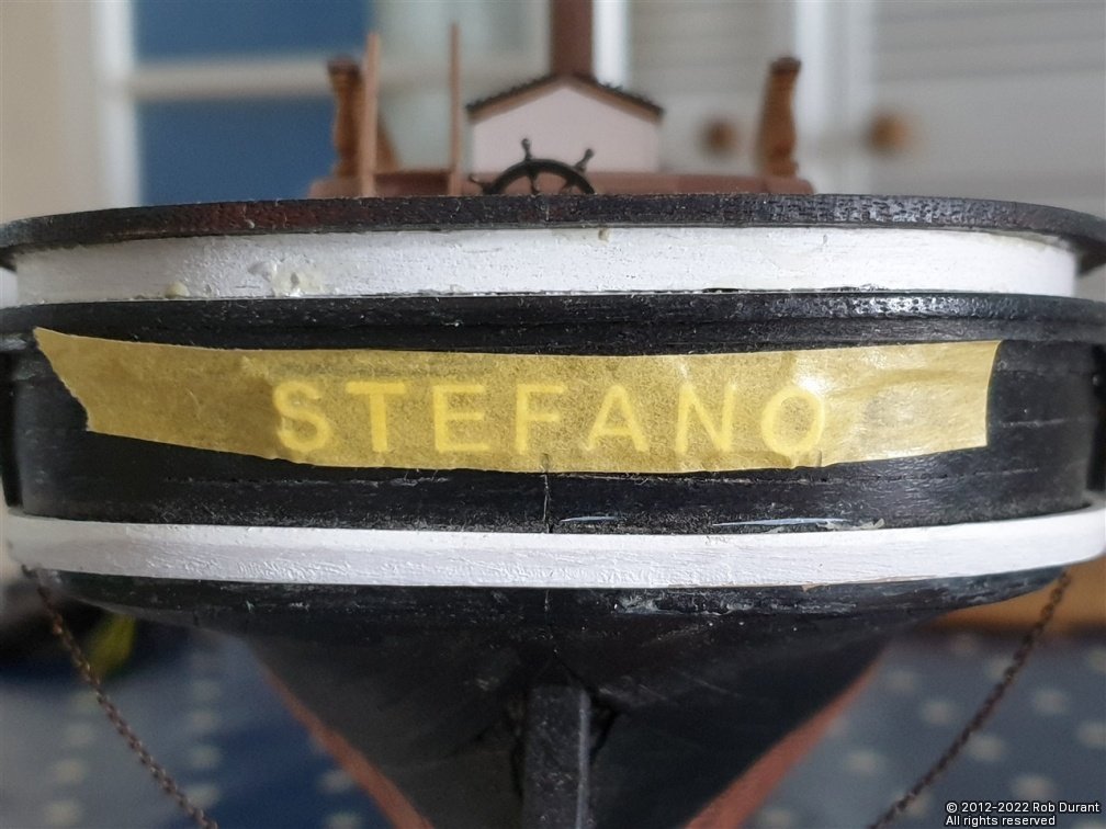
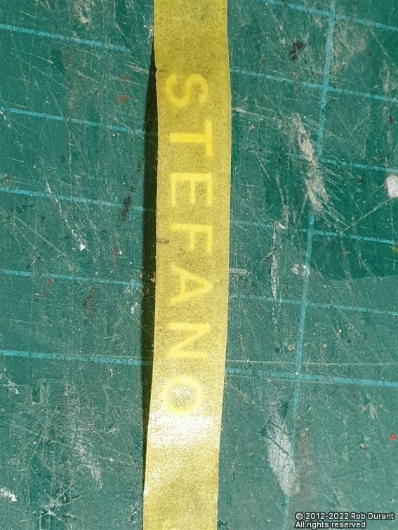
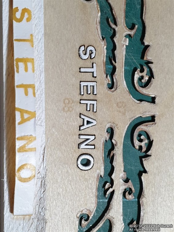
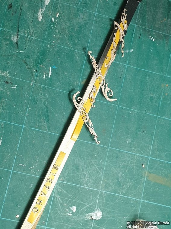
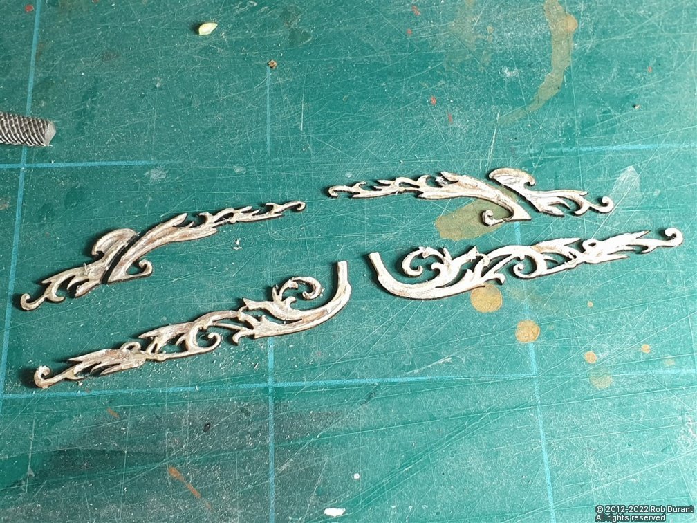
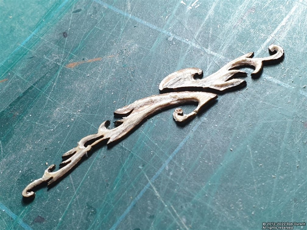
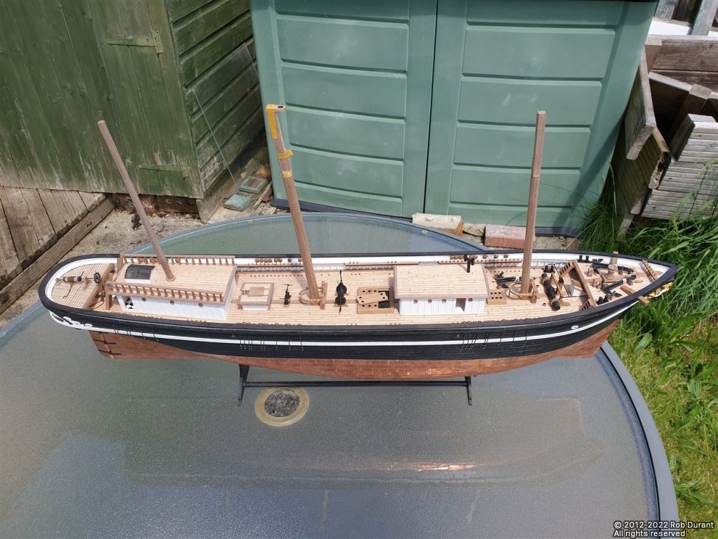
Hi all, Thank you for the likes. I've been doing more work on the deck furniture, and the hull decoration today... one of those days when you can really see the results of the work you've put in, which is always pleasing! 1. The companionway under the forepeak. This was built from styrene, to match the other deck houses, although being so small, I sanded in small rounded edges on the corners instead of using the larger 4mm corner styrene section. The roof was created using veneer as the false base, with beech decking, as per the deck and other deck houses, and 2x1.5mm walnut strip round the edges. The hatch was created in the same fashion as the aft companionway, and this one is glued closed, as there's no hole in the deck to simulate below decks. I've had a few attempts at the doors - not sure I'm happy yet, but at some point I need to bite the bullet and put doors in throughout the companionways and deck houses. The rough structure (this door was replaced later). Making the deck... And in situ (dry-fitted)... 2. Mast clamps... (61, 62, 64) These are laser cut. The fore and main mast bases need a slot filing in them to fit over the king plank. They also need the laser char removing and the top shaping. They will also need the inner edges filing to allow them to sit flat even though the mast passing through them is raked. The main mast base is from the 6mm laser cut panel, and will need sanding down by 2mm. 3. Hull decorations... These are made from thin ply, and need (very gently) shaping to give them depth and definition. I used my proxxon engraving set for this. You can see that even with a gentle touch, I managed to snap off the tiny scroll at the bottom. Thankfully, I found it after a quick search and it was a clean break, so it could be reinstated. Detail is shown on the plans, so you can draw the scrolls and details onto the parts before attacking them... For a first attempt, I'm really pleased at how they turned out. Then it was time to spray them. I decided to add the name to the stern at the same time. Once sprayed, the lettering was placed back into the ply holder to space them properly. Masking tape was stuck over the top, and then the letters were lifted out, still attached to the masking tape. Now, this masking tape could be turned over, and carpenter's (Aliphatic) glue could be added to the back, and the whole then placed on the stern. Once placed, the gaps on each side were carefully checked, and after a minute or so, I very gingerly removed the masking tape and used a dressmaking pin to remove the glue that had oozed out in a few places. Now it was time to add the decoration. This was easy enough for the parts in front of the curve at the stern quarter, as these parts sit flat. For the parts aft of these, they wrap around the stern, and so they were steamed over the spout of a boiling kettle, and then clamped very gently round a curve. This imparted the desired curve, and meant the glue doesn't have to hold this surprisngly tough ply to a curve. Instead, they could be glued on with very little pressure required. And here are the results. 4. Pin rails round the fore and main masts. These are deceptive little blighters. They're simple enough to make, but once you come to put the belaying pins in, even though I drilled the holes out really carefully, they split again and again. The rail itself is not ply, so on the curve, the grain crosses the part, and I must have stuck these back together at least five or six times in the process of getting all the belaying pins in. I'm hopeful that now the belaying pins are in place, they're going to add strength, but we'll see. I can well imagine the whole thing going ping half way through rigging - NOT an something I particular want to encounter! Once the glue's had a good chance to dry, I'll have another look at them and see if they're feeling strong enough. All in all, a very productive time! Here's a picture of the whole vessel... More soon Rob
- 286 replies
-
- 12
-
-