woodrat
-
Posts
836 -
Joined
-
Last visited
Content Type
Profiles
Forums
Gallery
Events
Everything posted by woodrat
-
 I suppose so. All is supposition until I get some answer from the archaeologists. I have been unable to find pictures of hatches from contemporary sources. Dick
- 263 replies
-
- 4
-

-
- nave tonda
- round ship
- (and 2 more)
-
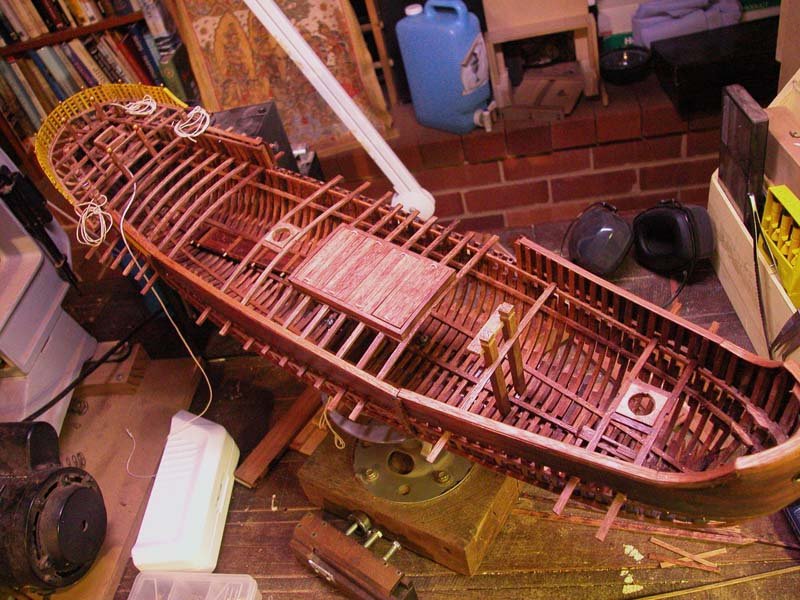
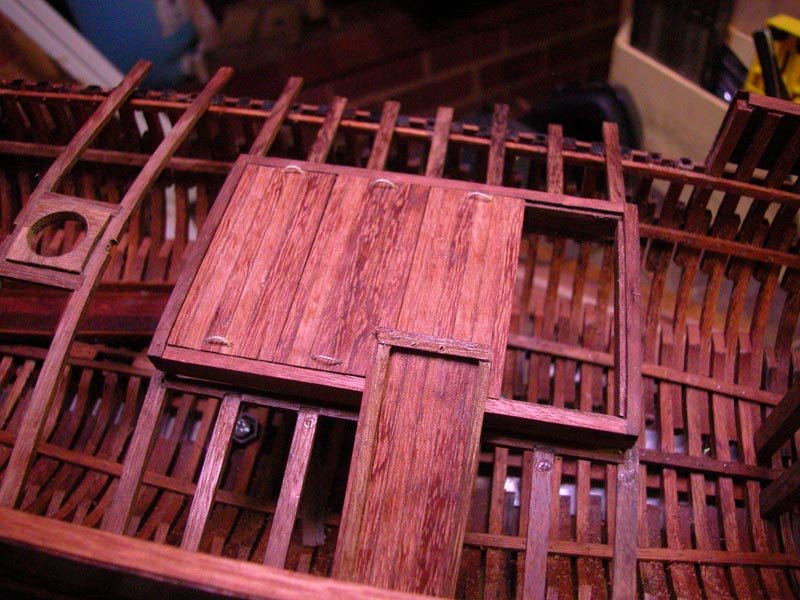
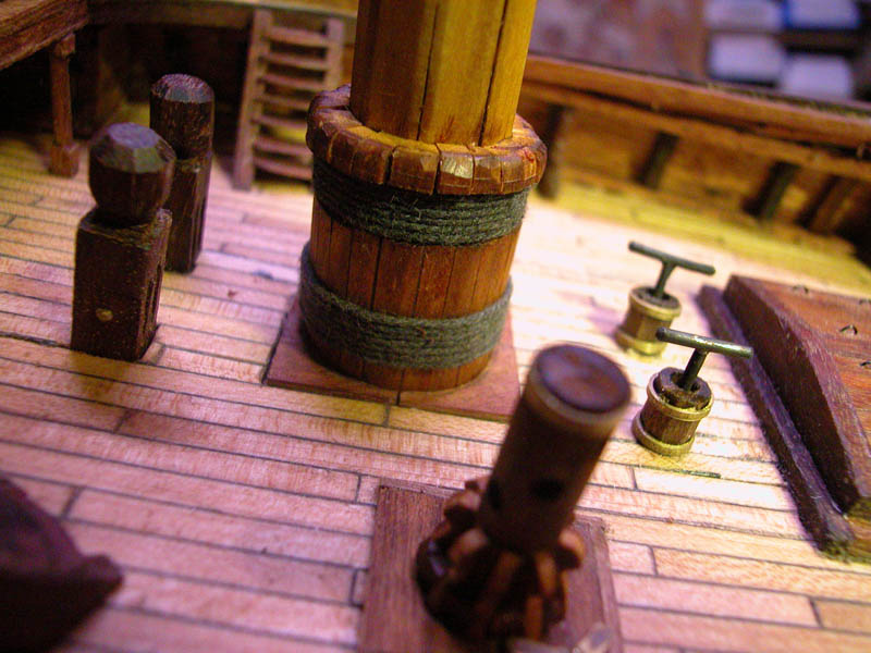
Have installed the mast partners, main hatch and bitts. Dick
- 263 replies
-
- 10
-
-
- nave tonda
- round ship
- (and 2 more)
-
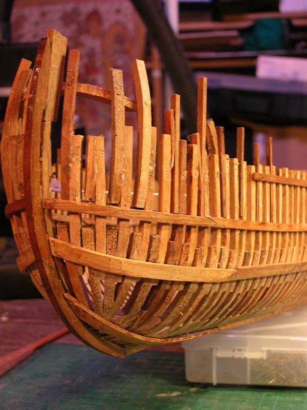
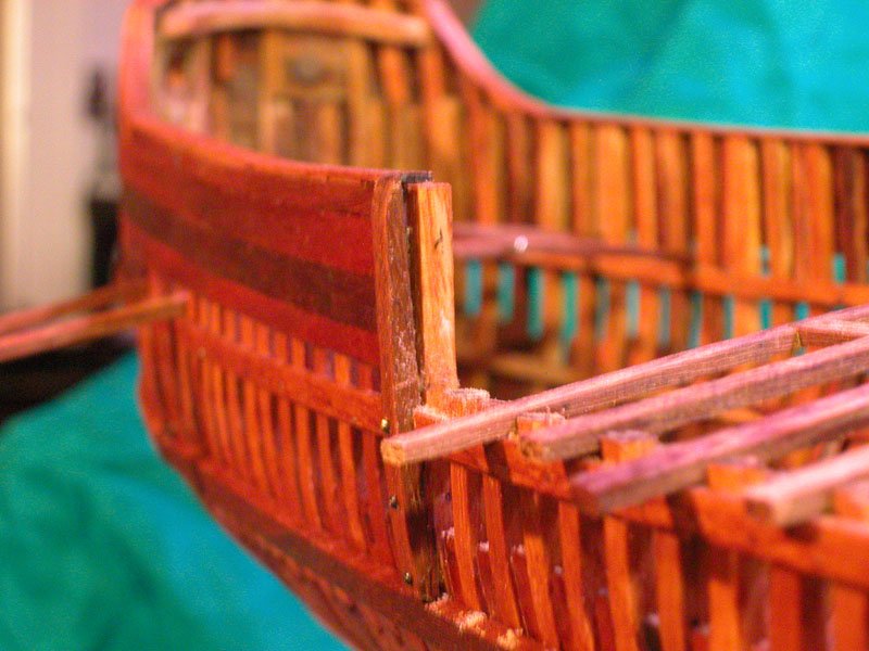
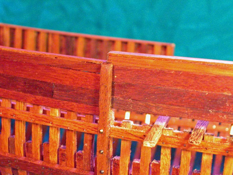
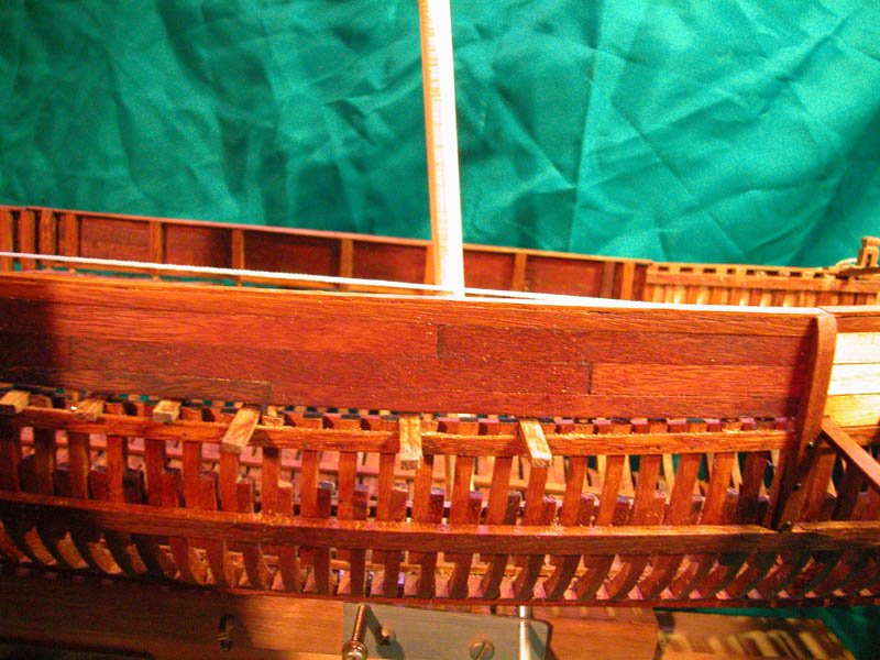
Thanks for those pics, Binho. Most Useful. The round throughbeams have also puzzled me. The vessel is said to be a "round ship" although not as "round" as what people conceived a round ship to be. The Contarina I wreck is about the same period as the Black Sea vessel but regional differences are important. Just look at the vast range of different types of hull and rig extant in the 20th century in the Arabian Sea. One of the unusual findings in the Contarina ship was the cut off of top timbers level with the deck in the mid section of the ship. Combined with this was the slotted timbers at each end of the gap. This seems to represent a removable section of bulwark. Is this to facilitate cargo loading or to allow sweeps to be deployed? No-one knows but I favour a combination of the two. In any case, I have included this feature in my model. The section of bulwark could be lifted by two men and slid into position Here is the rake of the main (forward) mast here is the rake of the mizzen (rear) mast Cheers Dick
- 263 replies
-
- 7
-
-
- nave tonda
- round ship
- (and 2 more)
-
Thanks, Binho. As I cant purchase the documentary in Oz, that would be most kind. Thanks also Mark and Steven. I do not plan to cover up any more of the hull framing. Partial deck plank it is. I have a tentative plan for the deck. It is largely driven by the position of the mast partners Dick
- 263 replies
-
- 2
-
-
- nave tonda
- round ship
- (and 2 more)
-
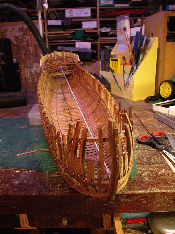
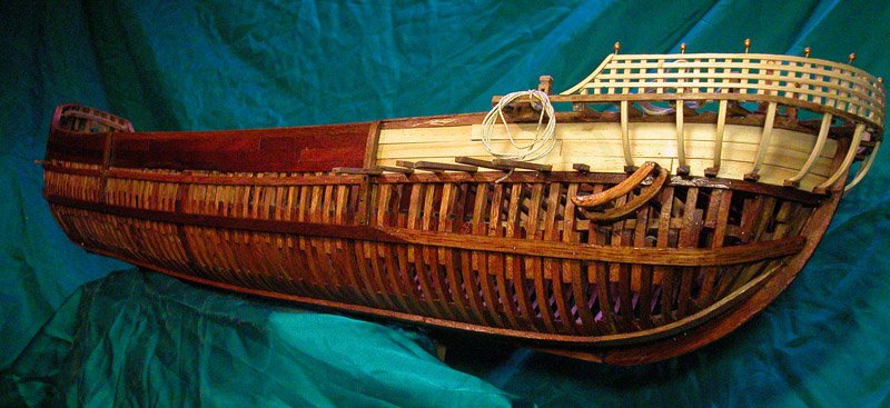
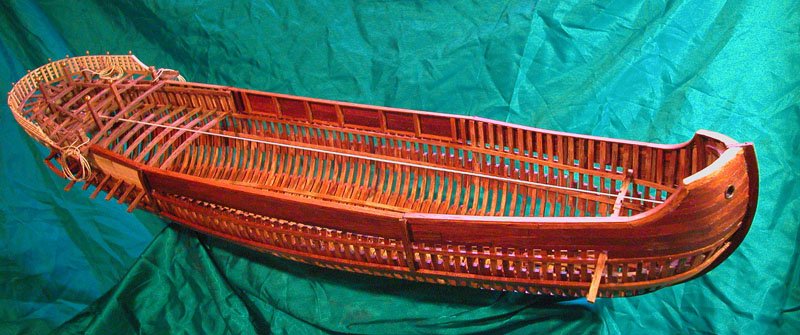
I couldn't help it! The wood was crying out for moisture. So I slavered on lots of orange oil and the wood said "thank you". The hull is largely complete. I now will attend to the deck framing, hatchways and machinery. This is contentious as no deck framing has survived from Contarina I and the I am likely to fall off the perch before I get answers from the Black Sea!! Anyhoo, the next question is whether to fully plank or partially plank the deck or not at all. Decision, decisions! Btw, thanks for the likes and general support for what is a fairly exotic subject cheers Dick
- 263 replies
-
- 12
-
-
- nave tonda
- round ship
- (and 2 more)
-
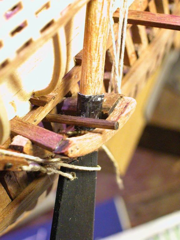
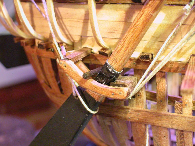
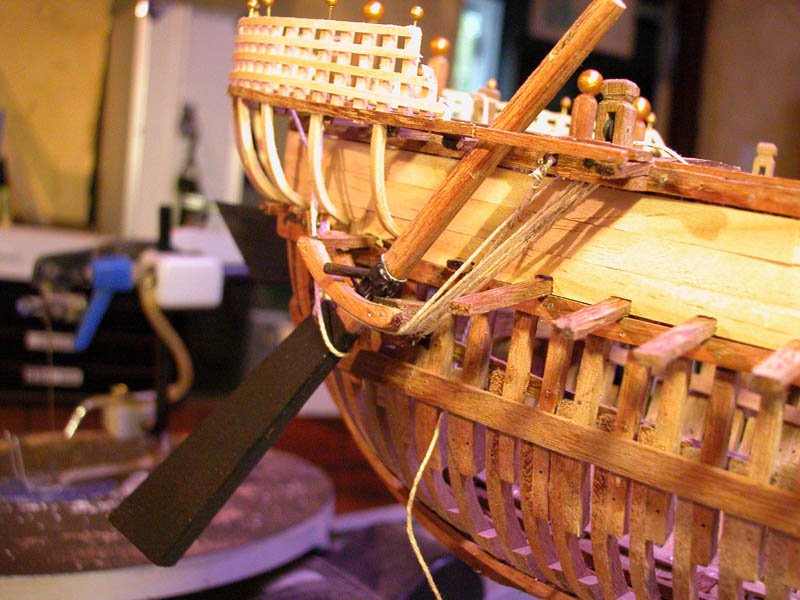
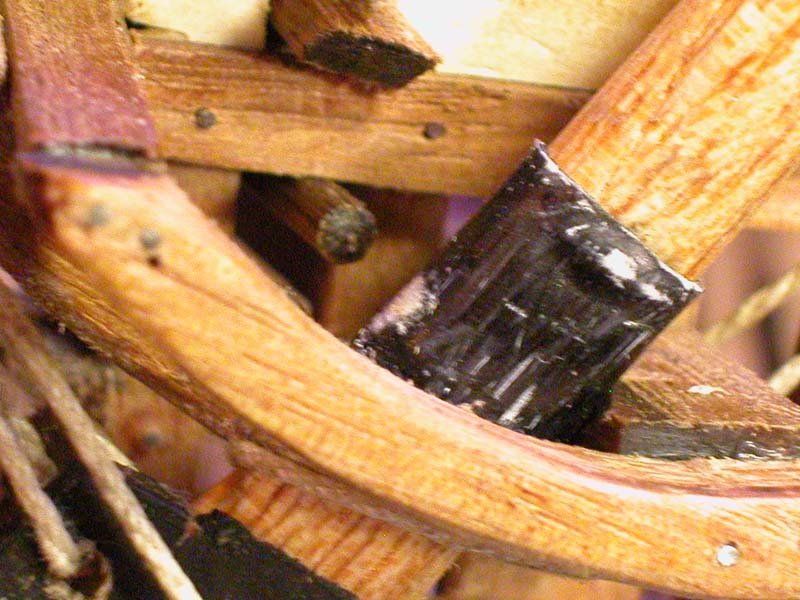
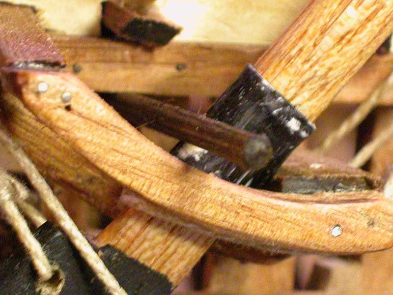
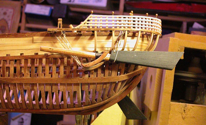
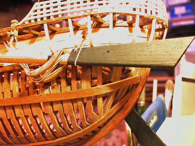
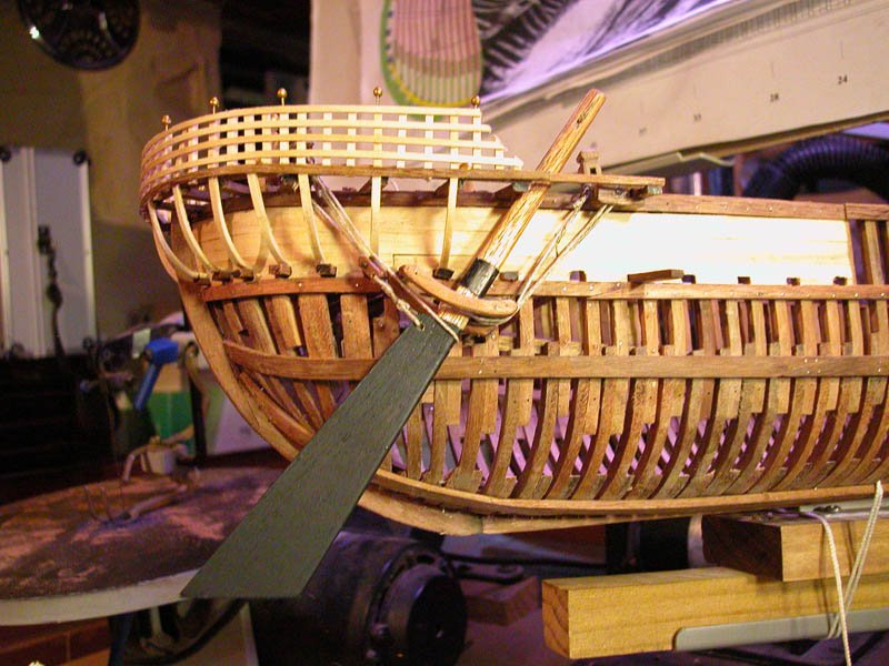
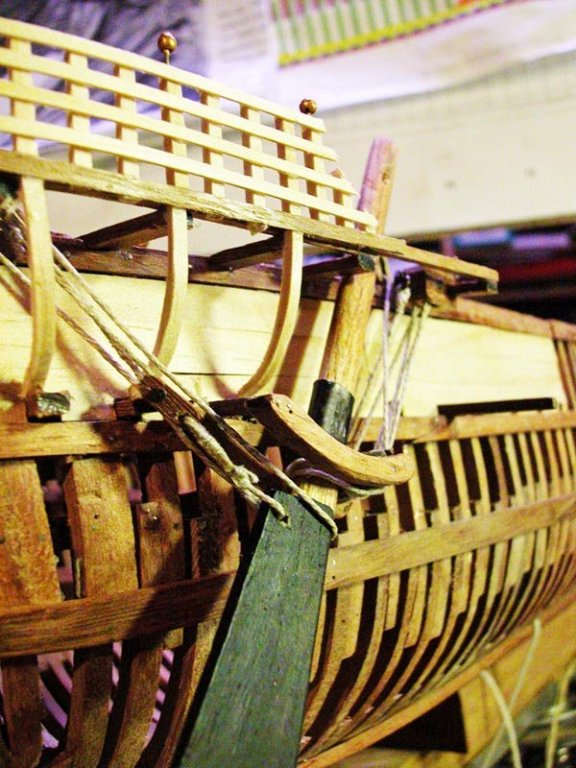
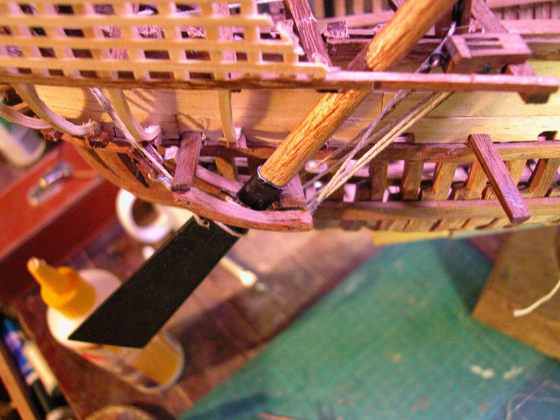
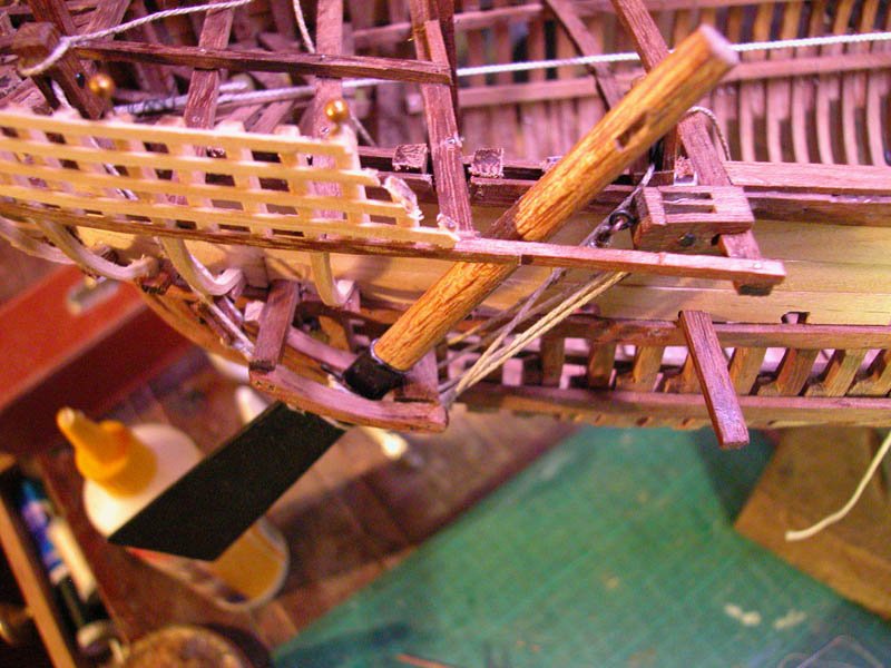
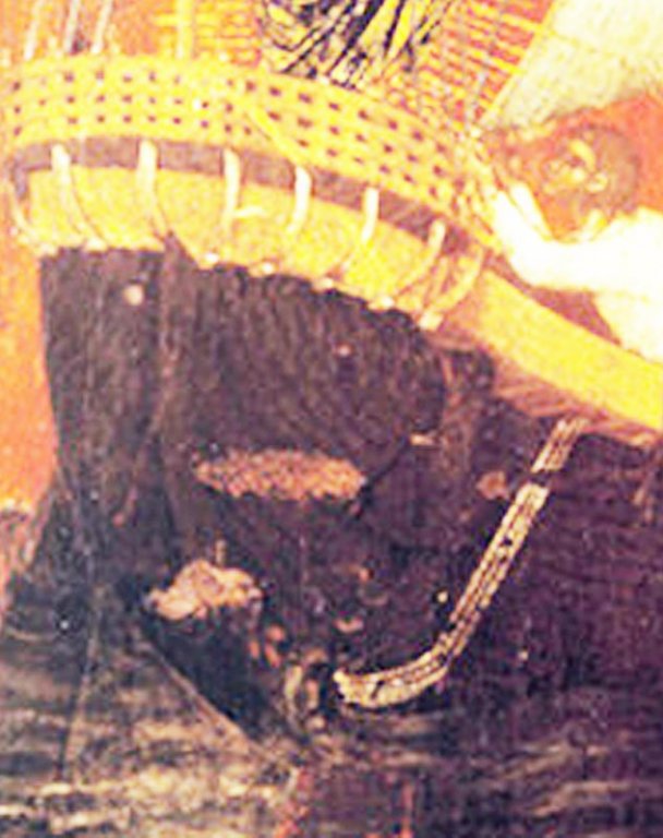
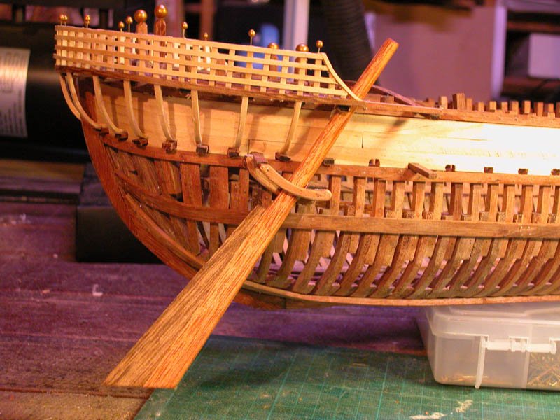
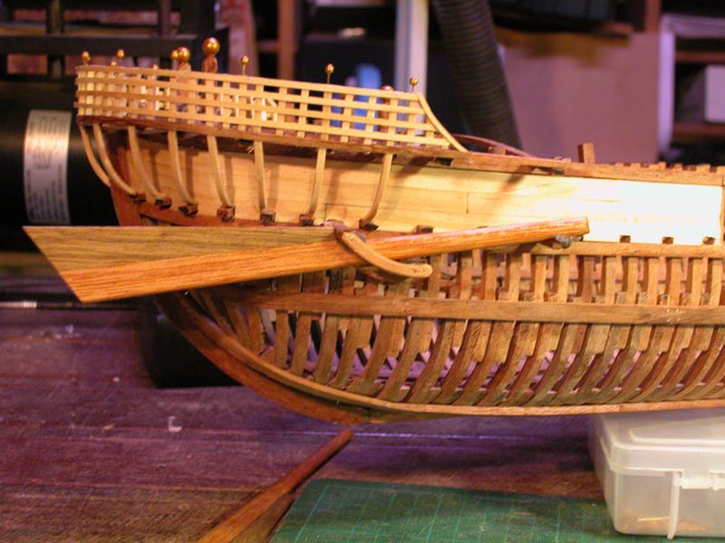
Shown here is the final addition to the quarter rudder mounting. This is a sliding rod (the dark rod ) which can slide in and out to lock the rudder against the lower through-beam. When it is required to raise the rudder, the sliding rod is slid back in. I believe this can be seen on the mounting of the Black Sea "round ship" Dick Slid out Slid in This is capture from the Black Sea video showing the quarter rudders from above and it shows the sliding rod as well:
- 263 replies
-
- 9
-
-
- nave tonda
- round ship
- (and 2 more)
-
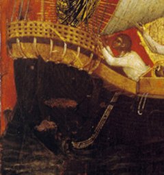
Thanks, Mark. In 1204 the blind Doge Dandolo, conspiring with his treacherous crusader partners, laid siege to, overcame and sacked with sickening slaughter the tottering Byzantine capital of Constantinople. Scuttling back to Venice with their loot (including the 4 bronze horses still seen on the facade of Sr Marks basilica) the venetians set to work to control the trading routes. The Byzantine empire was dismembered and Venice greedily clutched new possessions to her chest including the Peloponnese peninsula and Crete. Venice now controlled trade through the Adriatic, the Eastern Mediterranean, through the Dardanelles, into the Black Sea and as far as the Crimea. During the 14th century Venice was competing with its deadly rival the Genoese republic for control of the trading routes in the Mediterranean. After some scrappy battles, Venice was victorious, became pre-eminent in trade until superseded in the mid 15th century. Venice traded even as far as Northern Europe with its long range merchant galleys. Progressive loss of prestige and degeneration reduced the venetian republic to a shell until the latest bully Napoleon Buonaparte squashed Venice with his thumb in 1797. Here are some pics of the port quarter rudder in the up position. Note that the hoist is tight and the "uphaul" loose. Cheers Dick
- 263 replies
-
- 9
-
-
- nave tonda
- round ship
- (and 2 more)
-
Steven, I am at about the same point with my round ship. That is, working out masting, associated tackle and deck furniture/machinery. There is very little contemporary help and the Black Sea is keeping its secrets for the nonce. However, there are some illustrations 12th and 13th century which show the halyard block and tackle heading obliquely at about 60 degrees back to the lower halyard block which is just in front of the poop or steersman . This is analogous to the way it is done in dhows. The halyard tackle was more vertical in carracks and cogs. I would be cautious using 19th century lateen rig as a model. I believe the pulleys in the "calcet" should point fore and aft so the yard can fall forward away from the mast (pole mast or built?) Dick
-
Whatever type of truss you choose (and I don't think there are many wrong choices) you need to be able to loosen and tighten the truss with a tackle from deck level. The truss needs to be loosened to allow the yard to fall away from the mast (which is angled forward) so that the yard can be lowered or raised. It also needs to be loosened when the yard is transported around the mast during tacking (see Landstrom). Have you thought about where to put the halyard blocks? Dick
-
Thanks, Druxey and Steven. The tackle as presently rigged allows an arc of 60 deg. That is 30 degrees in and 30 degrees out. This all that is required to steer since having a foil cross-sectioned rudder at angles of attack greater than 30 degrees leads to turbulence and a probable stall at 45 degrees (Gillmer and Johnson 1982 , Introduction to Naval Architecture. Quoted in L Mott: The Development of the Rudder.) Cheers Dick

- 263 replies
-
- 3
-
-
- nave tonda
- round ship
- (and 2 more)
-
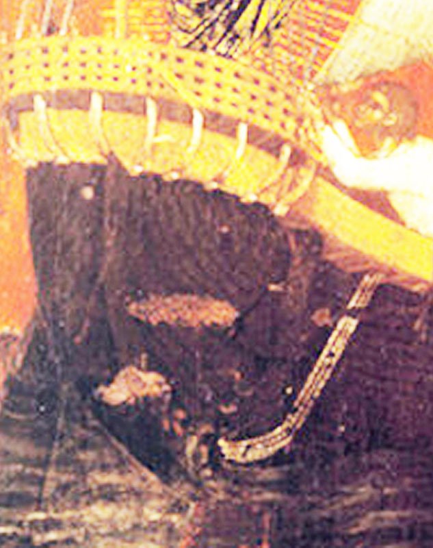
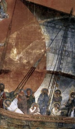
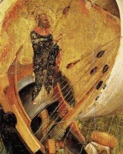
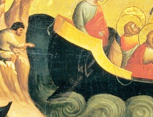
I have rigged the starboard quarter rudder using a system which I believe is shown in the Veneziano painting of the translatio of St Mark. The only way I could do this was to use a double pulley on the "uphaul" and with the ropes going under the throughbeam around the rudder and back up to the pulleys. The rudder hoist I have left as single pulleys. With the rudder in the down position the hoist is loose and the uphaul tight and pulling the rudder against the throughbeam. Dick
- 263 replies
-
- 12
-
-
- nave tonda
- round ship
- (and 2 more)
-
I don't think it makes one iota of difference! Dick
- 263 replies
-
- 1
-
-
- nave tonda
- round ship
- (and 2 more)
-
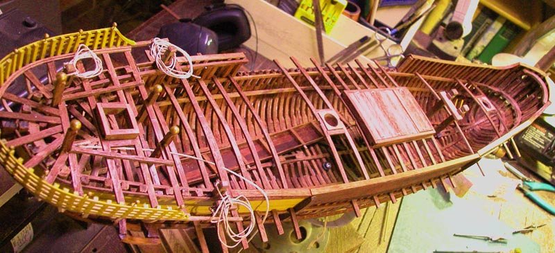
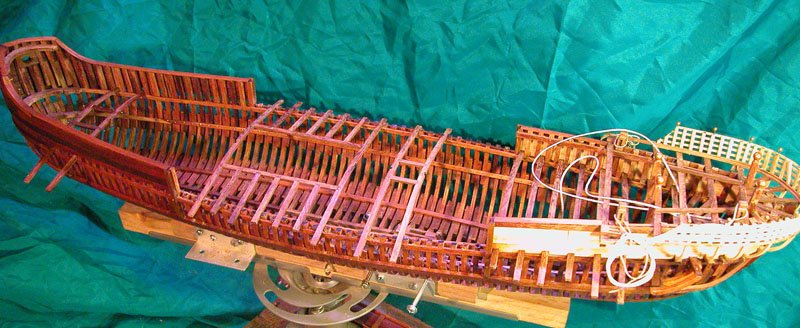
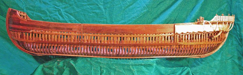
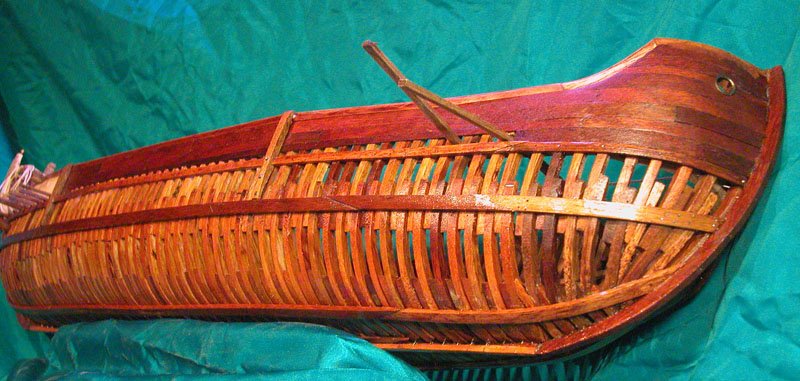
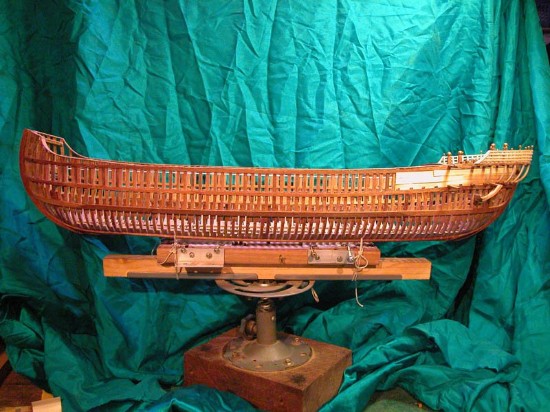
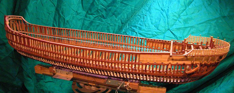
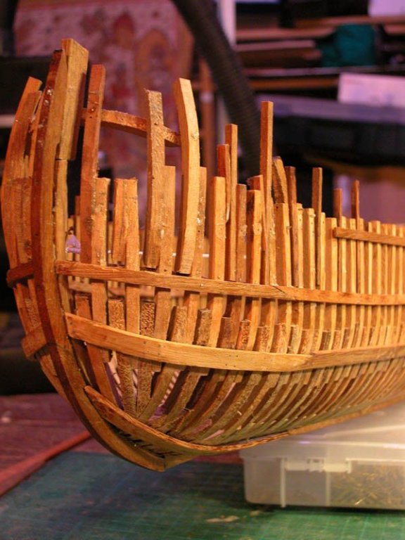
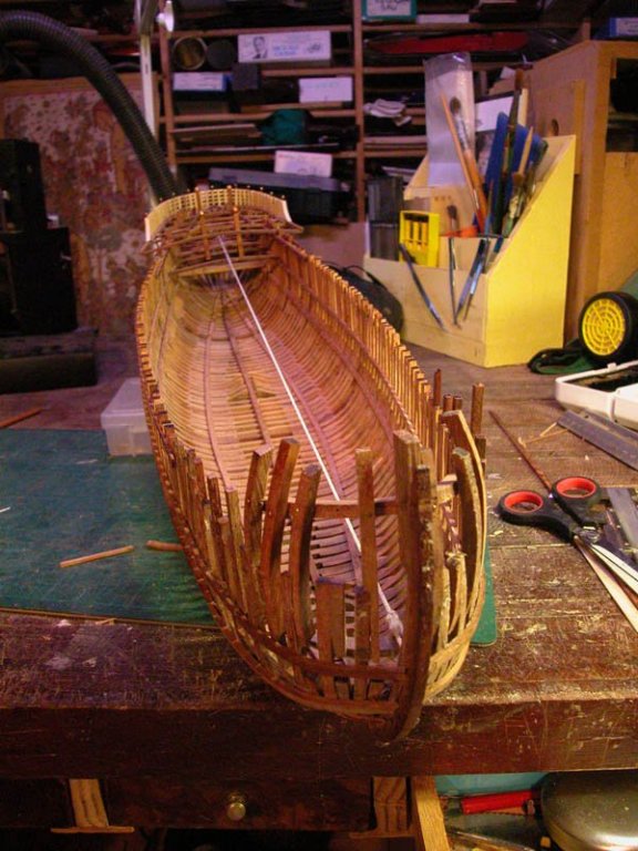
The hull framing is complete and looks more tidy. Now to plan the deck beams Dick
- 263 replies
-
- 11
-
-
- nave tonda
- round ship
- (and 2 more)
-
Steven, I have had a message from Prof. Mauro Bondioli. In his learned opinion, rudder blades were indeed coated with pitch. Dick
- 263 replies
-
- 3
-
-
- nave tonda
- round ship
- (and 2 more)
-
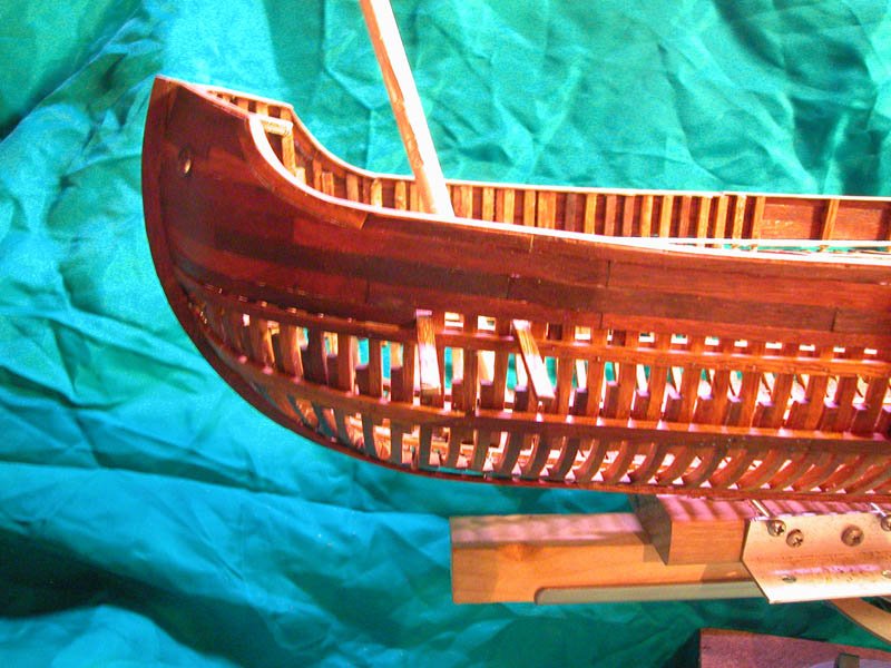
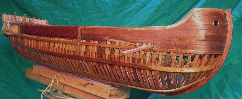
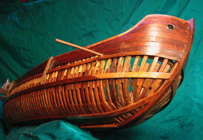
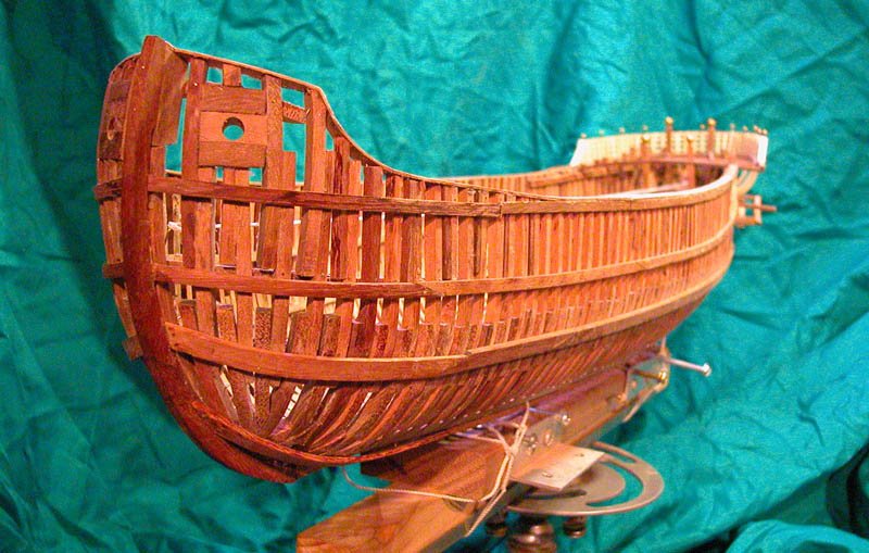
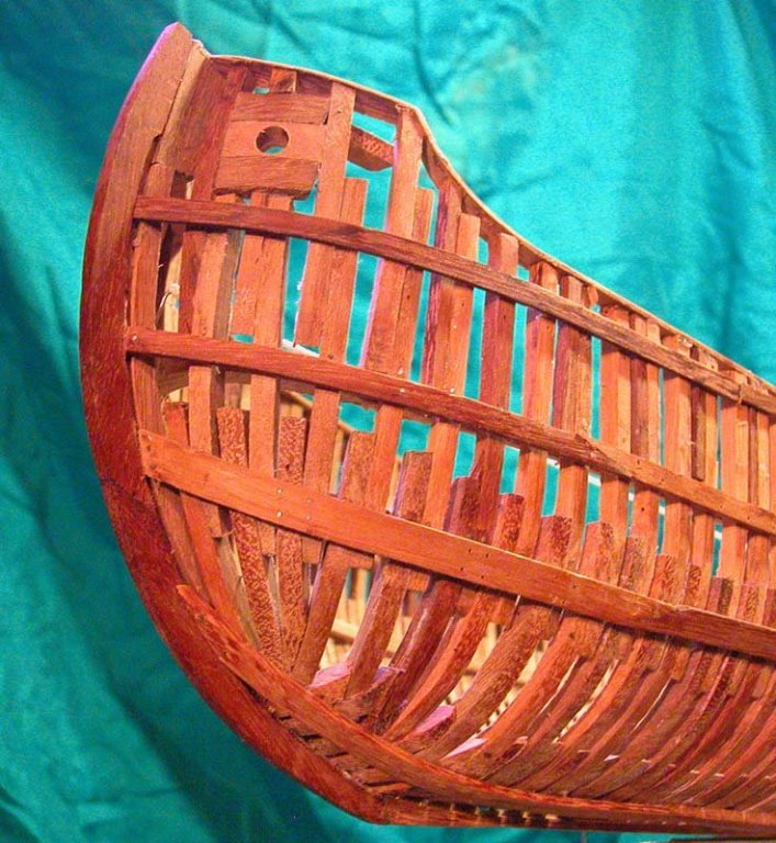
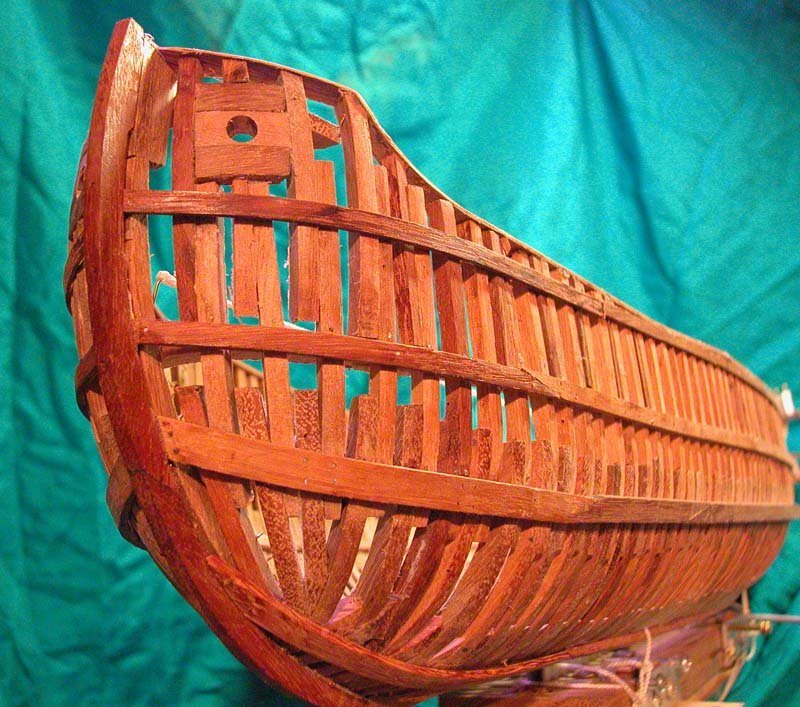
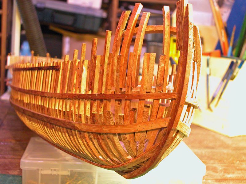
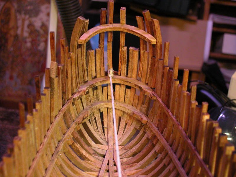
Here are pics showing the framing of the bow and hawse timbers which need to be strong. Dick
- 263 replies
-
- 13
-
-
- nave tonda
- round ship
- (and 2 more)
-
No. The aft end of the curved guides (inner and outer) is permanently fixed to an extended beam. To remove the rudder when in port all that is required is to disconnect the rudder hoist and "uphaul". The rudder is reversed out of the mount with the help of a boat. The rudder then is floated off and towed away by one of the boats. It is reinstalled in the opposite manner, again with the help of a boat. That is my interpretation. Also, do you think that the rudder blades were coated with pitch? The MIchael of Rhodes manuscript shows the blades blackened. Dick
- 263 replies
-
- 2
-
-
- nave tonda
- round ship
- (and 2 more)
-
Alberto, what is your specialty in archaeology, if you don't mind my asking? Dick
-
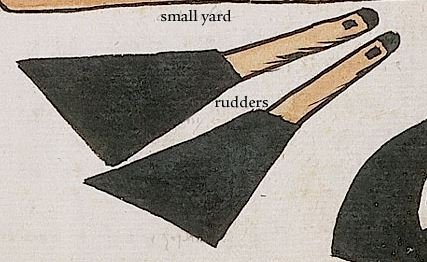
I closely read Lawrence Mott's thesis. the poop superstructure is based solely on Veneziano's Pala Feriale transport of St Mark, as is the bow structure (to follow soon). The length of the rudders is 1/3 of keel length (Fabrica di Galere and Michael of Rhodes) Having fun. Dick
- 263 replies
-
- 4
-
-
- nave tonda
- round ship
- (and 2 more)
-
Thanks, Alberto for the links to Twitter. They did work and I have had a good look at the mediaeval merchantman from 13th century. The rudder mount seems to tally with mine and I feel somewhat encouraged. The Contarina I wreck upon which I largely based my reconstruction has been tentatively dated to 1300 and so can really be regarded as a 13th century vessel contemporaneous with the Black Sea example. Unfortunately Amazon wont ship the video to Australia and Amazon Australia has never heard of it. It will turn up somewhere, I suppose. I am now turning my attention to the bow which is more bluff than the Black Sea vessel. Here are pictures of the quarter rudders in the down and up position. Cheers Dick
- 263 replies
-
- 16
-
-
- nave tonda
- round ship
- (and 2 more)
-
verrry interesting! I have not heard that. Can anyone clarify this? The wedges were solidly hammered in and woolded. It would be no mean feat to take them out and replace them for an extra knot or two even if the mast did not go by the board. Keel-haul the captain, I say! Cheers, Dick
-
The structures surrounding the mast base at deck level are indeed wedges inserted around the mast at the mast partners. These wedges are then tightly woolded with stout rope (see my cocha build). Without these wedges at deck level, the strain on the mast foot would lead to early failure. The coin needs to be byzantine of the correct period, I agree. Dick
-
Steven that foremast looks like it has a curve to it. Love the poop super structure. It would make sense to use wedges. Don't forget the coin under the mast foot. Dick
-
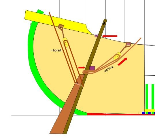
Thanks Steven Attached is a rough draft of the rudder and its tackle as I see it. Rudder curved guides are not shown. The hoist and "uphaul" are shown. The forces holding the rudder to the throughbeam and upper beam are shown as red arrows. This system will allow easy re-installation of the rudders and easy raising . Of course the uphaul would need to be cast off to allow the hoist to raise the rudder. I will demonstrate this later when I have made the rudders. It is rather like the system shown in Veneziano paintings ( one of the more reliable artists) Cheers Dick
- 263 replies
-
- 8
-
-
- nave tonda
- round ship
- (and 2 more)
-
For what it's worth, having read and re read Lawrence Mott and reviewed contemporary iconography, I am coming to the view that most artists did not know what they were drawing or carving. They represented what they thought they saw. They might, for instance see curved rudder guides in a swing mount and interpret them as ring or box mounts or even through-the-hull jobbies. Artists are unreliable draughtsmen but produce tantalising representations. I await the publication of archaeological results from the Black Sea. Were any rudders found at Yenikapi? Dick
- 263 replies
-
- 2
-
-
- nave tonda
- round ship
- (and 2 more)
-
Thanks Steven. A couple of these are new to me. The Veneziano in particular shows detail of the poop deck which I was puzzling over and is very helpful. Some of the others such as the San Pietro in Ciel d'Oro - Pavia show the curved guide timbers much as I have done them. The Sant'Eustorgio is gorgeous and shows the rudder hoist and downhaul ropes well but looks like a box mount . It is hard to see how the rudder could swing up. Cheers Dick
- 263 replies
-
- 1
-
-
- nave tonda
- round ship
- (and 2 more)