HOLIDAY DONATION DRIVE - SUPPORT MSW - DO YOUR PART TO KEEP THIS GREAT FORUM GOING! (89 donations so far out of 49,000 members - C'mon guys!)
×

woodrat
-
Posts
835 -
Joined
-
Last visited
Content Type
Profiles
Forums
Gallery
Events
Everything posted by woodrat
-
 At least get "Vanguard of Empire". Are you thinking of building a carrack or other style of mediaeval ship?
 -
An excellent starting point is Roger Smith: "Vanguard of Empire" Oxford Press. Other reference for iconography is: Lillian Ray Martin : "The Art and Archeology of Venetian Ships and Boats" Texas A&M Books Articles by Mauro Bondioli in : "The Book of Michael of Rhodes vol 3" Long, McGee and Stahl eds. MIT Press Of Course The volume in Conways History of the Ship " Cogs Caravels and Galleons" is a very useful starting point as well. Dick
-
The modification of the stempost is relatively minor and would make it resemble both Oliveira's plan and the Trombetta manuscript more closely.

-
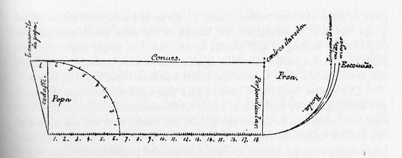
this is the present stempost and the modified version according to Oliveira , a Portuguese. Is this more like the original? Dick


-
Thanks, Steven, the sternpost rake was calculated by contemporary geometric techniques as used by the shipwrights in the Arsenale. Incidentally it happens to tally with the Mataro model closely. Dick
-
MDF board also has health risks due to formaldehyde glues and wood fibre. Good ventilation is required as well as face mask and eye protection if sanding or using power tools on it. A good shop vacuum is a wise investment. Here is a relevant link: http://www.wisegeek.com/what-are-the-health-risks-of-mdf.htm Dick
-
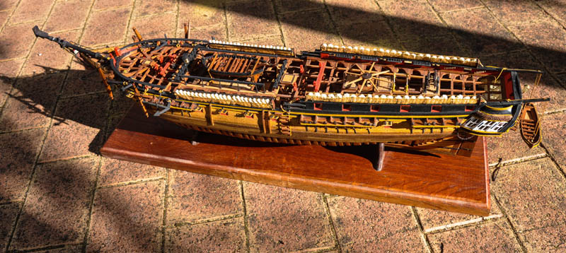
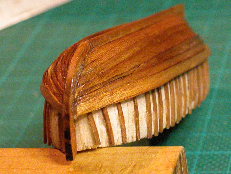
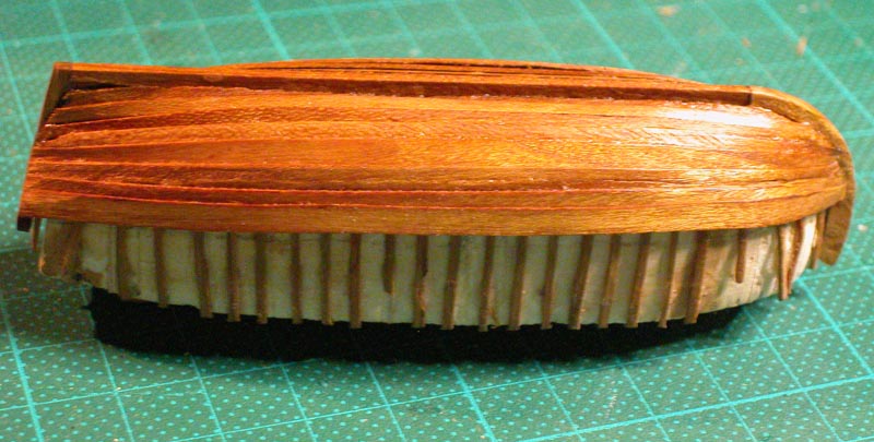
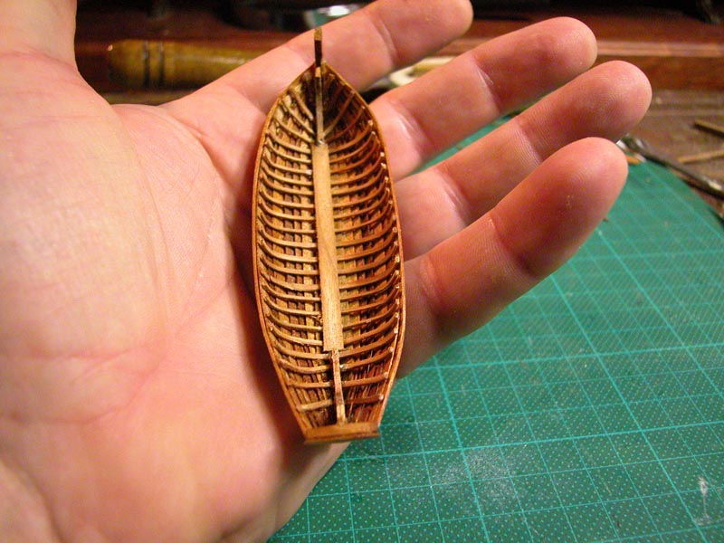
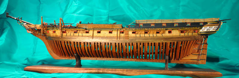
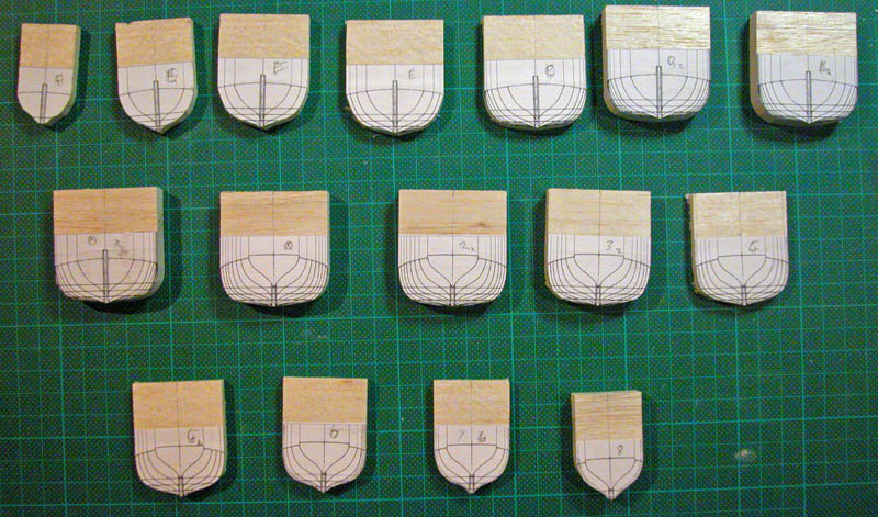
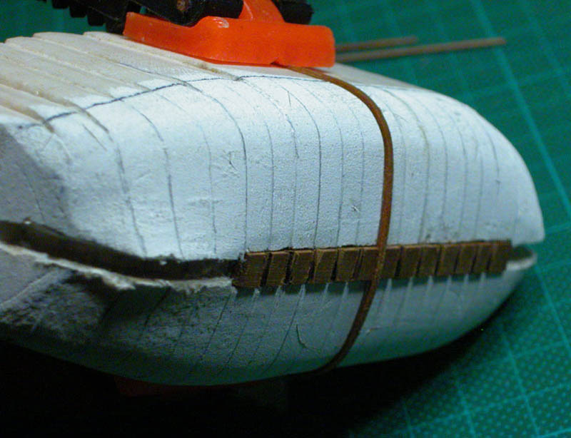
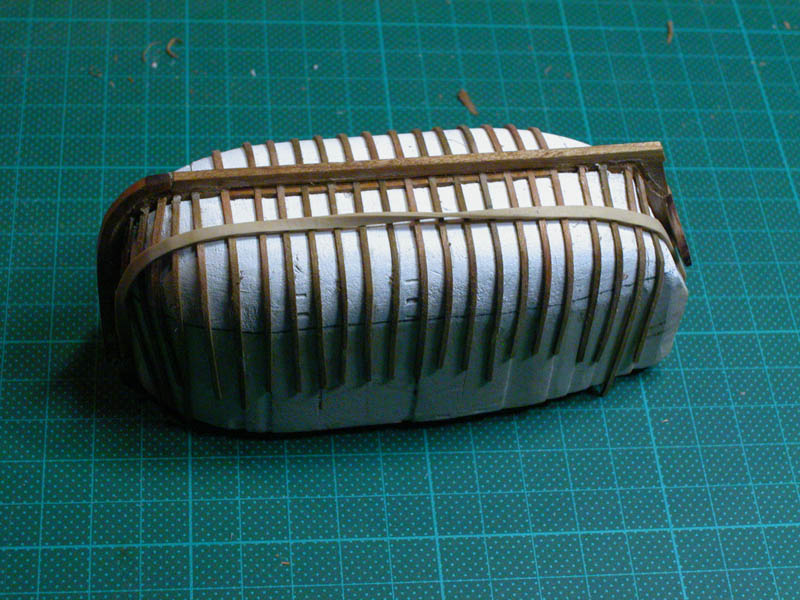
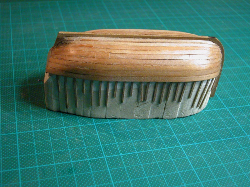
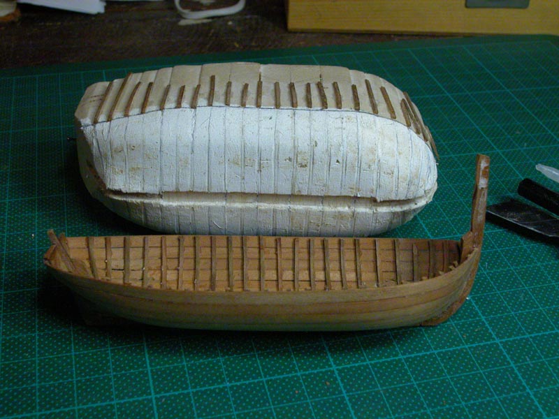
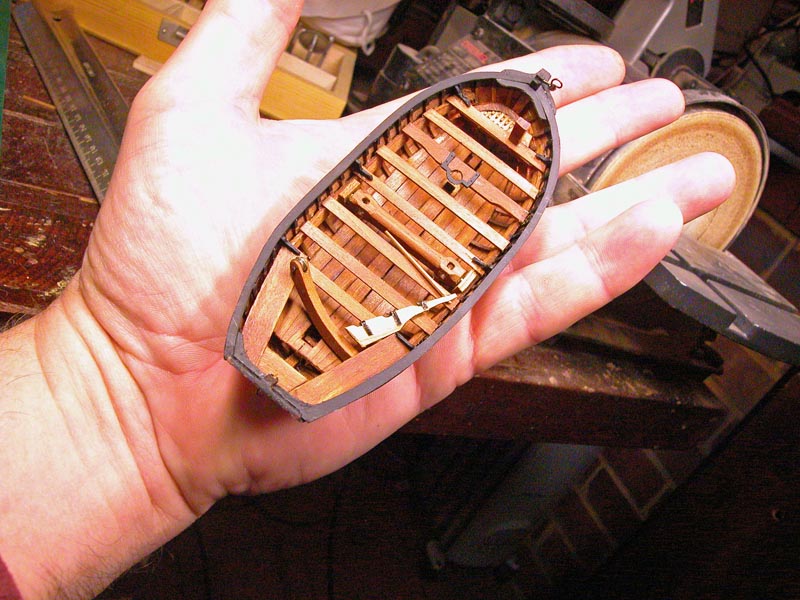
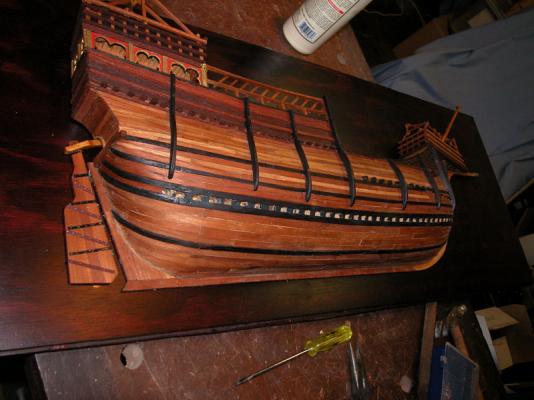
Before I get too involved with rigging, I have to build the full hull . This is new to me as I have never done a POB model before. Nor have I designed one. I am making this up as I go along. I hope you guys will forgive any egregious errors and make suggestions as I go. Here goes, this is the central bulkhead support with the backbone of the ship
-
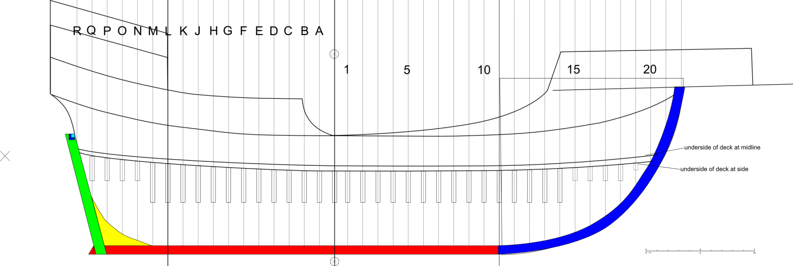
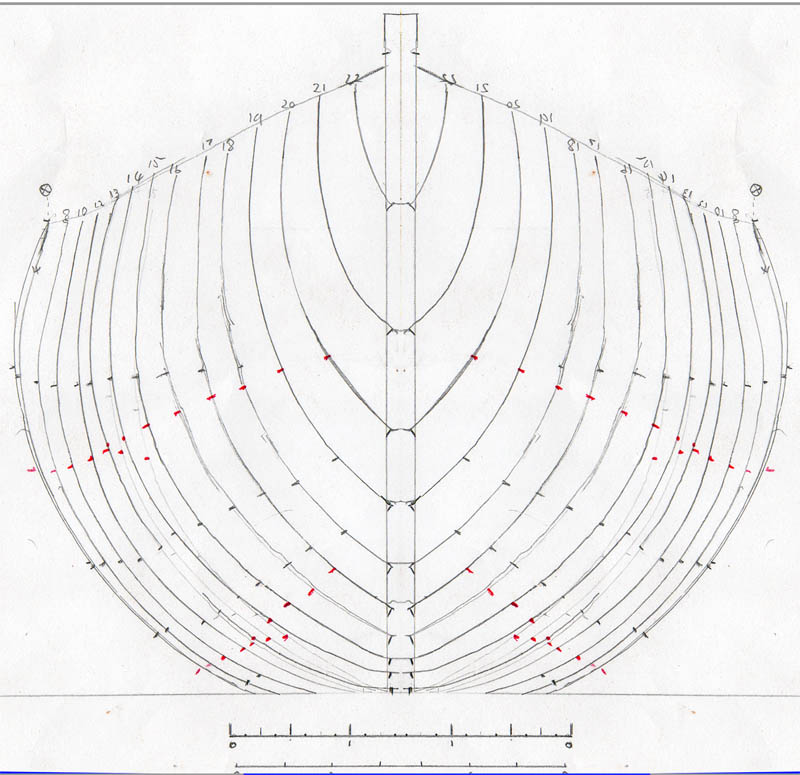
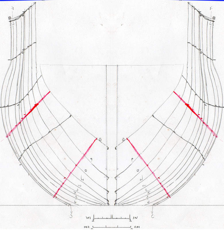
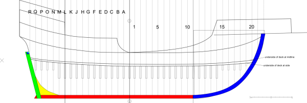
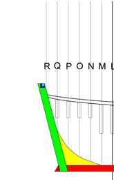
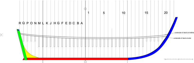
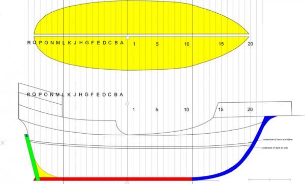
the TAMU files are a wonderful resource and we must be grateful to them for making them available to lubbers like us Here are the lines of the carrack to date [][][]
-
Thanks to Mooonbug and well done on your reworking of the AL Santa Maria. Good choice to have a round tuck stern. The rigging of my carrack fills me with trepidation, however. Dick
-
Yep, I did consider it but decided against it. Please see previous posts for the reasons. Yes, Crackers, there is guesswork but it is also detective work with many clues and many suspects here are some preliminary lines, which will be cleaned up. Dick

-
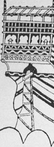
Thanks, Steven for the pics which will be of interest to many MSW readers. The Reixach carracks seem to be closest to the carrack I am reconstructing. It also shows a sailor ascending ratlines but they are not drawn in. The most realistic depictions of carracks by far are by Carpaccio. I am presently drawing up lines to build a 1:64 POB full hull model. Dick

-
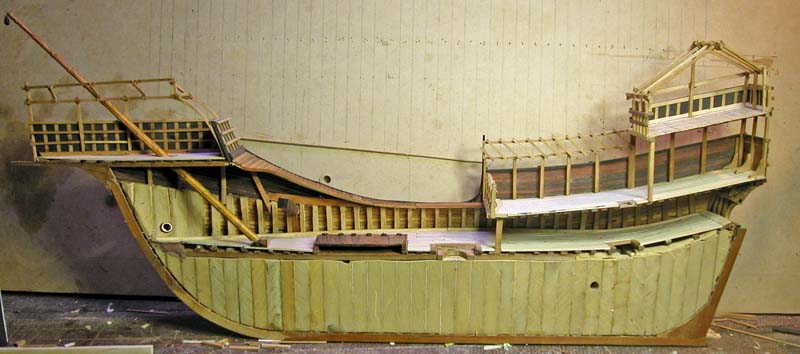
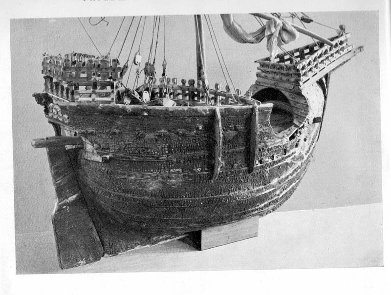
Louie, I have been fascinated by the english carracks in the Richard Beaumont drawings. These seem to be sketched from life and show much interesting detail. Some show ratlines and others Jacob's ladders. Thanks for the link. Druxey and Doreltomin. Another reason not to place the ship on a mirror was the fact that it was not symmetrical. the bowsprit (if that's what it was) is shifted to the starboard side of the forecastle (a feature seen in many pictures of the period). Dick
-
Have fun with your build, Cookster. It is a beautiful ship. Dick
-
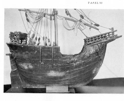
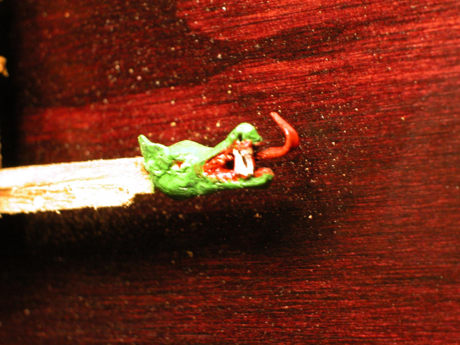
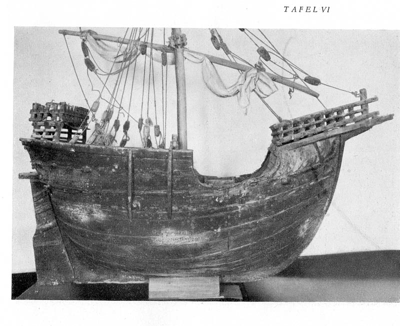
I did consider a mirror and tried one but, because of the thickness of glass over the silvered layer, it looked like there was a huge gap down the middle of the ship and I gave up on the idea. Besides, there is a venerable tradition of half-hull models and I rather like the way they look. Thank you Louie for the article on Master W A +. This will be very useful. I think Landstrom in his excellent book uses the Mataro nao but lengthens in in the mid section to make it seaworthy. the wooldings on the masts in two of the pictures indicating masts made of several pieces of wood whereas the small nao by W A has a one piece mast. Also noteworthy is that, in the first picture, the yard has been lowered to the deck, presumably it was the way they did a harbour furl. The dragon


-
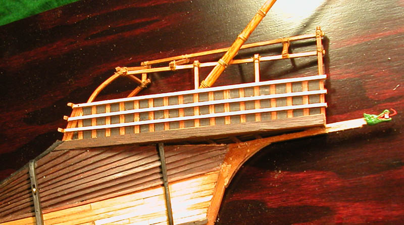
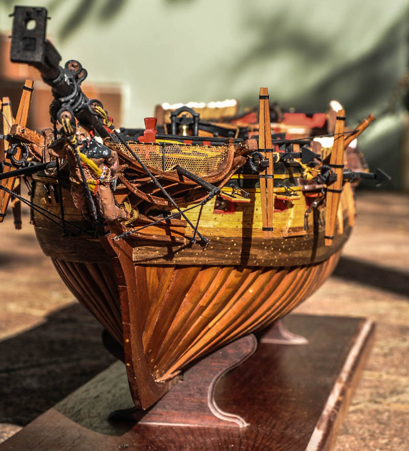
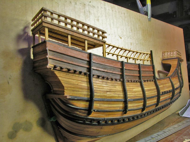
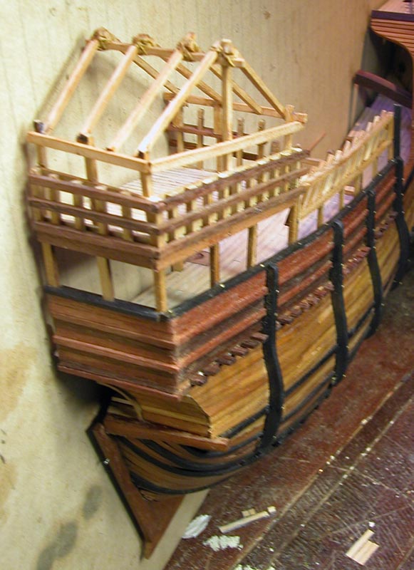
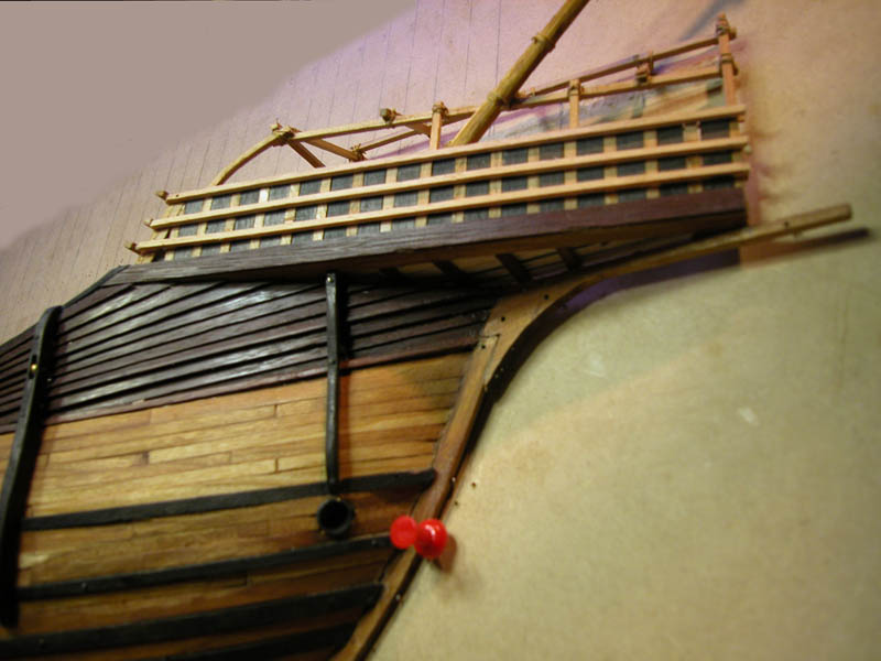
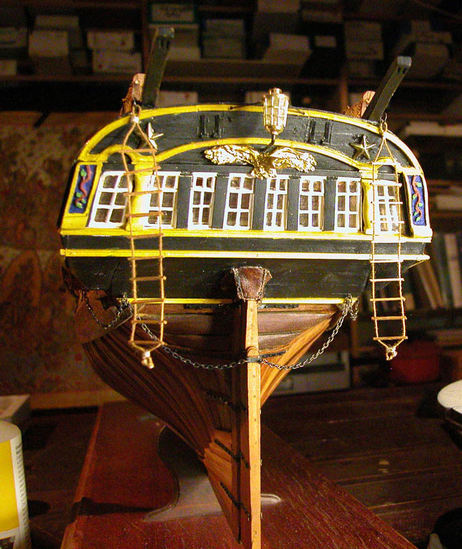
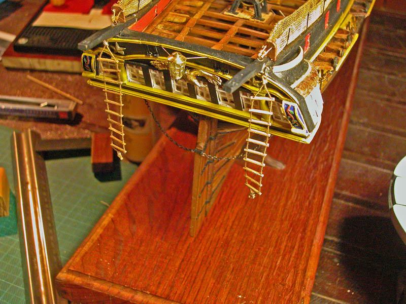
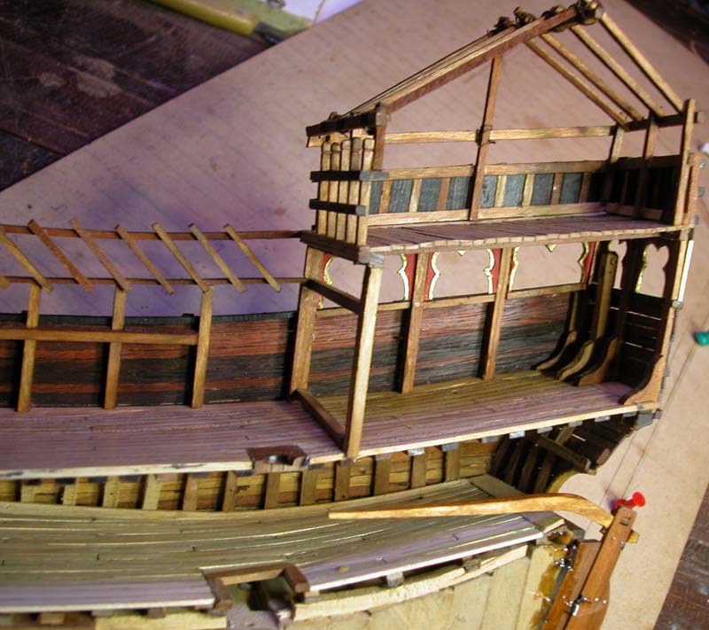
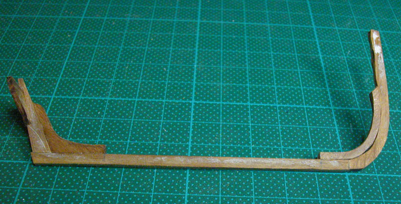
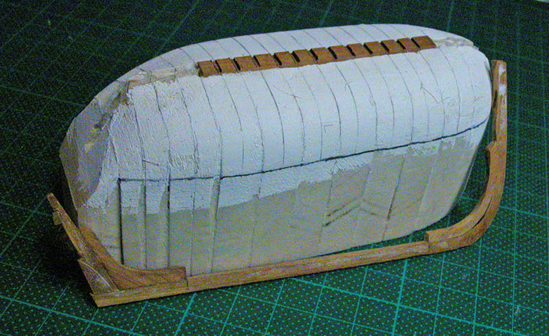
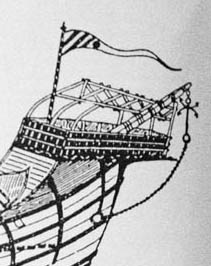
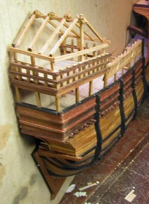
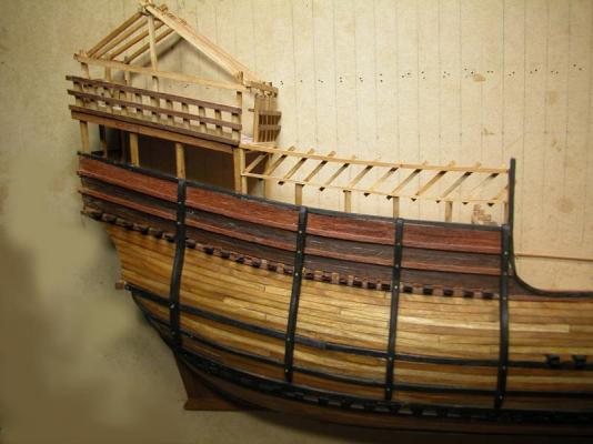
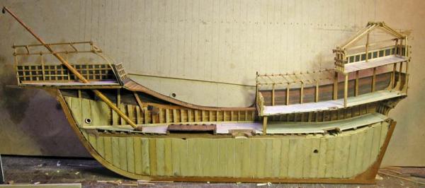
Thanks, Doreltomin. It is unfortunate that the Mataro nao has been interfered with so much over the centuries but it is the best we have. It is a challenging project . Here are some views of the temporary framework used to support awnings on the stern and fore castles. Also the eccentric "bowsprit"
- 632 replies
-
- 10
-

-
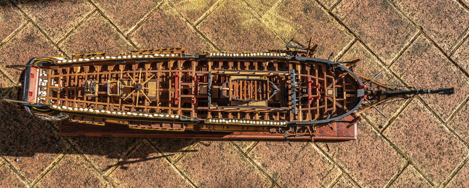
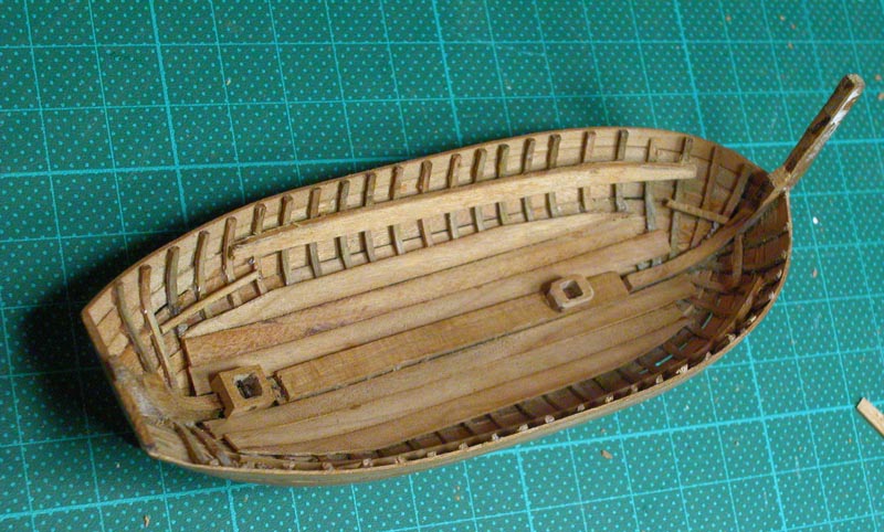
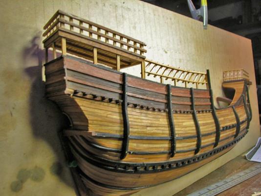
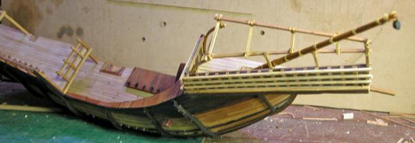
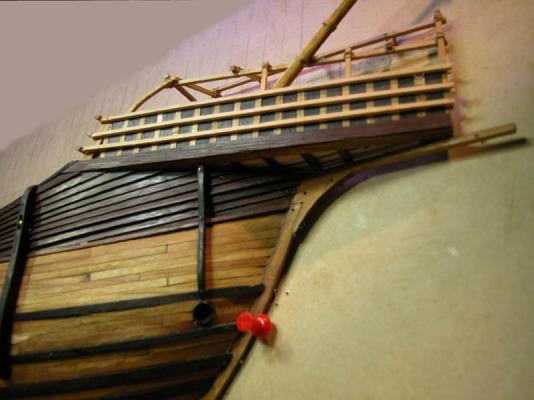
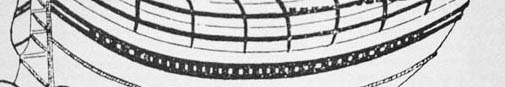
Have removed the "deck beams" and exposed the underlying bituminised "frames". The planking between the wales left off. Looks more like the illustration Dick
-
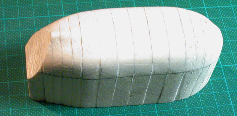
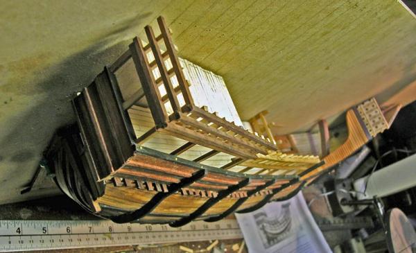
The fore and aft edges of the blocks are always perpendicular to the keel. Problem solved. Have to change the model now Dick
-
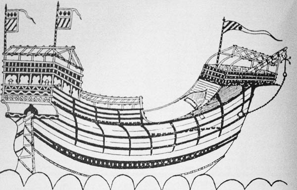
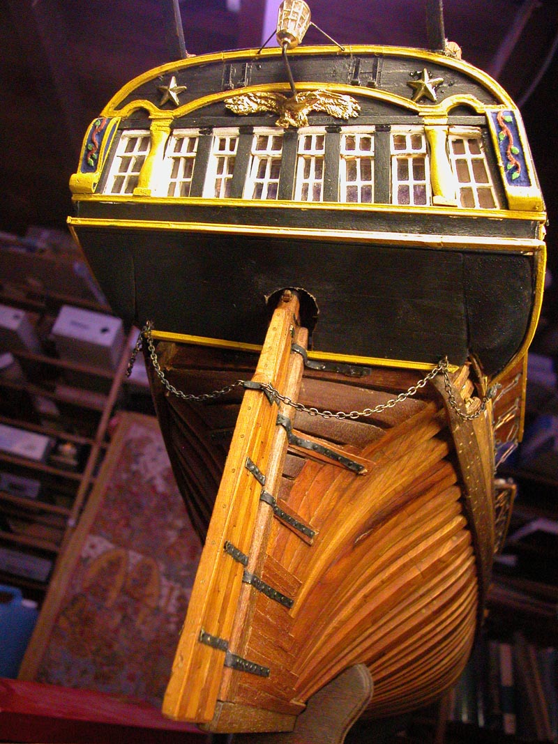
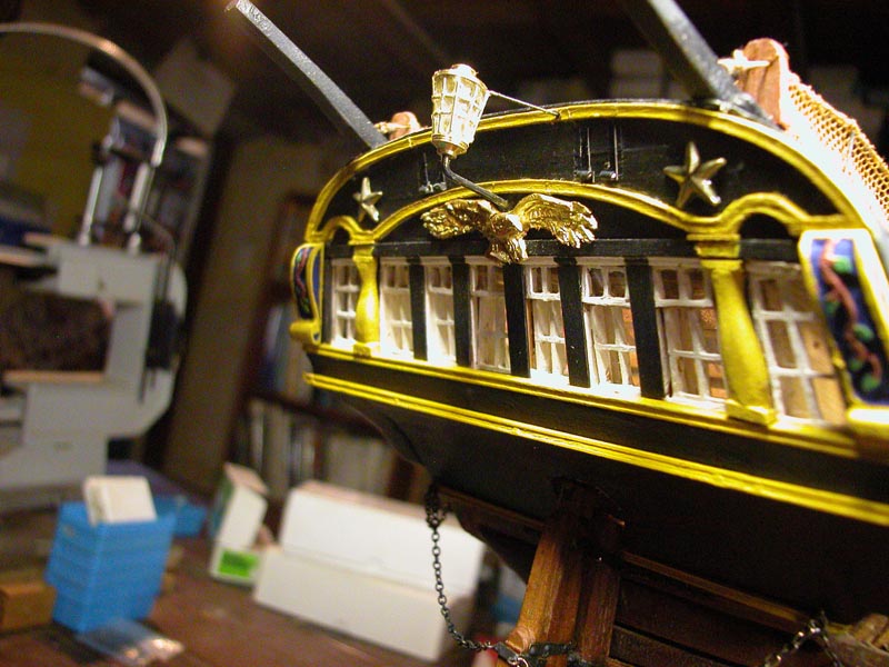
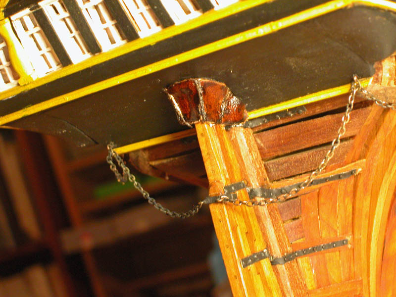
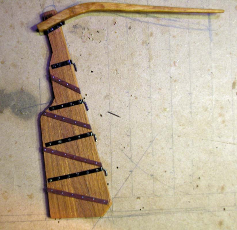
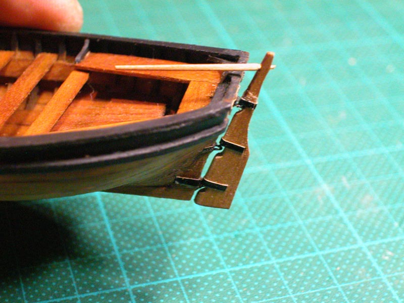
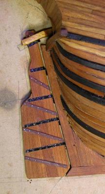
Another thought. Perhaps the ship in drydock is in the process of being planked and the strakes between the main wales are not yet in place. The square blocks could be the underlying frames. :mellow: Dick The rudder is made of several pieces with wooden battens and metal straps reinforcing. Note the curve of the tiller.


-
Thanks, Crackers. But if you think the evidence for hull construction is poor, wait till you see what's known about mediaeval rigging!!! I do, however, have a cunning plan to do a full hull with rigging. The half-hull was sort of a proof of concept model. But first I must finish Le Gros Ventre. Dick
-
Or one ot two archaeological finds! I can find no other reference in my books of nautical archaeology to projecting beams below the waterline but sheathing is well attested. Any nautical archaeologists out there?
-
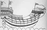
Thanks Druxey, Bob, Vivian and Doreltomin. Great work Vivian on your caravel, keep posting. You raise a good practical point, Druxey. The Mataro nao shows no projecting beams below the waterline, but the Trombetta nave definitely shows this My theory is this: The drawing was done with the ship out of water in drydock. No masts. Whole hull visible The ship may just have had all its outer sheathing removed and awaiting new sheathing. Sheathing was a layer of sacrificial planking over other materials (hair, bitumen tallow, etc) which protected the hull against shipworm This nave was a a largeish size vessel and the projecting beams below the waterline may have been required to prevent torsional problems. the outer sheathing may have helped to caulk the projecting beams and cover them. Alternatively, the dotted area between the wales may not be deck beams at all! If so, what do they represent? There are no known wrecks of venetian round ships from this era so this is all speculation. What do you think? Any other ideas in MSW Land? Dick