HOLIDAY DONATION DRIVE - SUPPORT MSW - DO YOUR PART TO KEEP THIS GREAT FORUM GOING! (Only 13 donations so far - C'mon guys!)
×

woodrat
-
Posts
835 -
Joined
-
Last visited
Content Type
Profiles
Forums
Gallery
Events
Everything posted by woodrat
-
 That's an option worth considering. But the carracks at that time lowered the mainyard in order to furl the sail, which would obscure the deck detail somewhat. Thanks Jesse and Steven for your kind comments Dick
-
Thanks chaps. I still have some deck furniture to do before I can tackle the rigging. The perennial question remains, furled or not furled. . I am tending towards furled as it would be a good way to depict how they raised the bloody great ponderous mainyard by muscle power alone! Dick
-
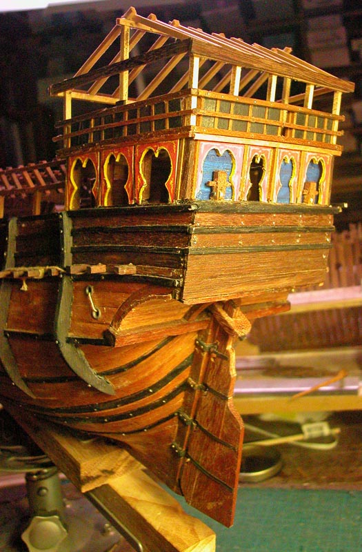
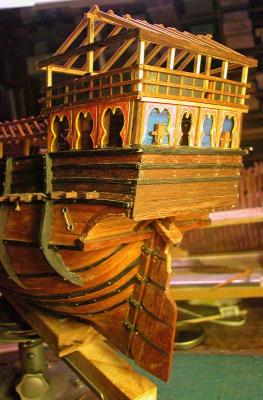
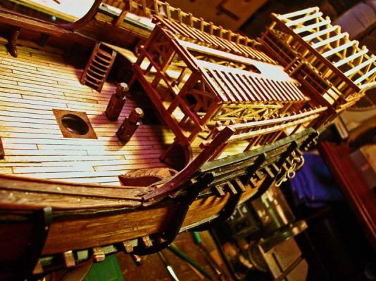
Thanks Carl and Steve. The blinds are meant to hinge up out of the way. You can also see them on the Matthew reconstruction. Dick
-
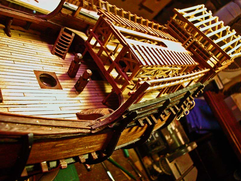
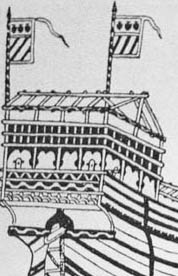
here are some pics of the stern gallery. I have left some blinds down and some up (coloured blue). Dick

- 632 replies
-
- 17
-

-
Yes, sure am. Stripes seem to be blue and white. I will also include a lion of St. Mark on the quarterdeck. Dick
-
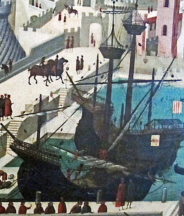
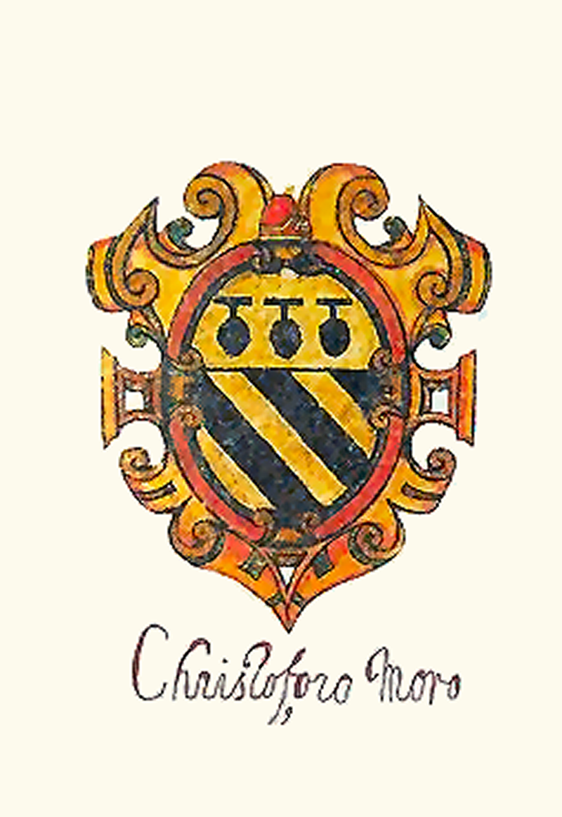
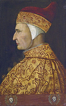
"Breaking News!" After a lot of fruitless searching of heraldry sites, I believe I have now identified the owner of the carrack in Trombetta's illustration. I believe the flags are those of Doge Cristoforo Moro (1390 – November 10, 1471) who was Doge from 1462 to 1471 which places him smack in the right era This is his family crest which matches exactly the flags on the ship the round things may be pomegranates this is his portrait Dick

-
Steven, is there any indication in the Yenikapi wrecks whether the keels have a convex curve in them or whether they are straight. Some mediaeval shipwrights deliberately built in a curve to make it easier to beach the galley. Dick
-
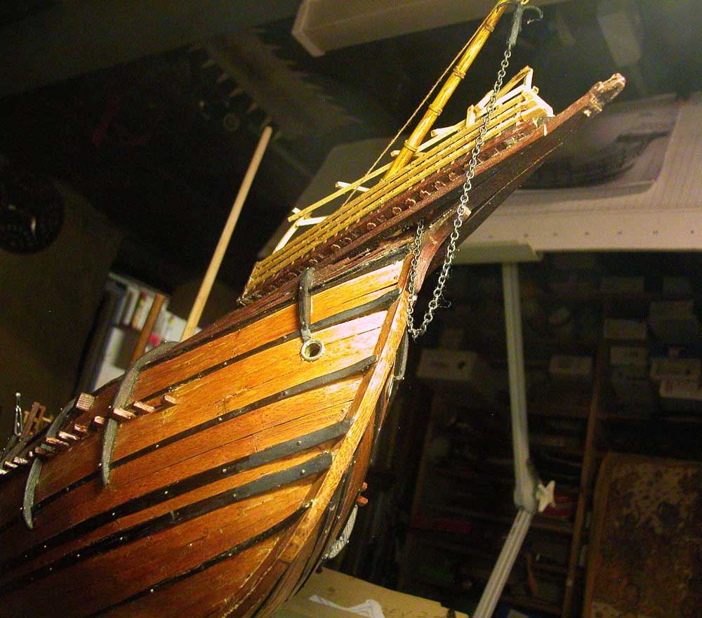
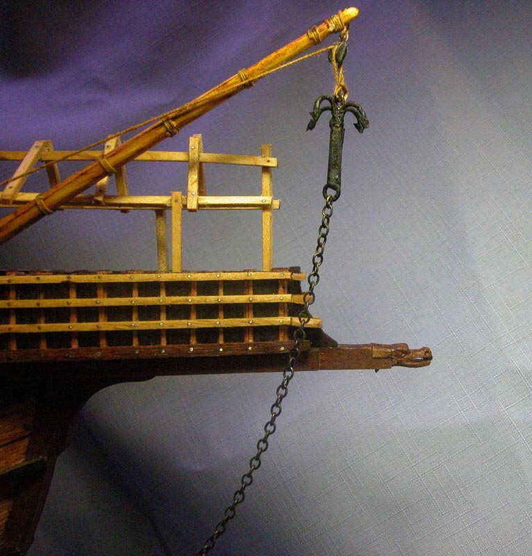
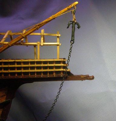
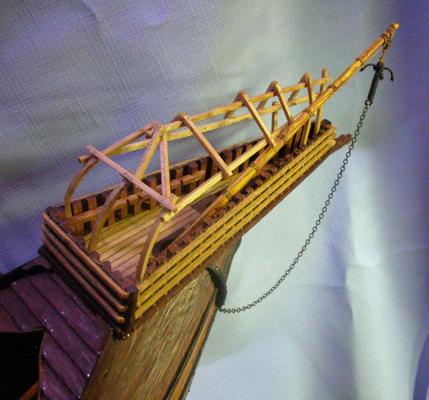
I have corrected the placement of the grapnel chain so it does not foul the hawse. I suppose the grapnel cable could still be led to the windlass if needed. Dick


- 632 replies
-
- 13
-
-
That is most kind in you, Druxey. It is very satisfying to try second-guessing the shades of long dead shipwrights. Dick
-
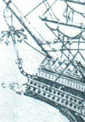
Thanks Carl and Steven. I have gone back and looked through my picture bank and found some good detail on the disposition of the grapnel. All of these illustrations seem to show the chain being led into the floor of the forecastle, not the hawse holes (I will change this) The nice chain, Steven, was a leftover from a kit that I trashed. I waste nothing. Certainly hooks are seen on later warship carrack yard ends but are not seen on these early carracks. I remain to be convinced that the grapnels were designed for offensive use against other ships except in extreme emergency. I believe I now have the answer. Grapnels were a common form of anchor for dhows and other vessels of the Indian ocean and were used to assist mooring in tidal estuaries or tidal flats at low tide. They were also used to help haul the dhow out to deep water at high tide. (Clifford Hawkins: The Dhow, an illustrated history of the dhow and its world). the dhows suspended the grapnels from the bowsprit and sometimes used chain instead of cable.I believe that this would have been the practice in the tidal lagoons such as Venice where the large anchors could not have been used (as seen in the Barbari map of Venice) Cheers Dick

- 632 replies
-
- 11
-
-
Thanks, Carl. I am speculating here. I am far from clear about this myself. The grapnel is only an auxiliary anchor. The main anchors are much larger. The grapnel may be used for manoeuvring the ship in harbour. I doubt it was used to grapple other ships. The grapnel chain is attached to a cable which is led into the forecastle, maybe through the hawse holes ( i dont believe this now. see posts below).The windlass could also be able to assist and the grapnel cable could be wound onto the tranversal bitt. What is the exact function of the transverse bitt and how is the main anchor cable attached to it? No detailed contemporary pictures show this detail although one picture shows what may be the anchor cable wound around the bitt. This is guesswork but I would appreciate all suggestions. Dick
-
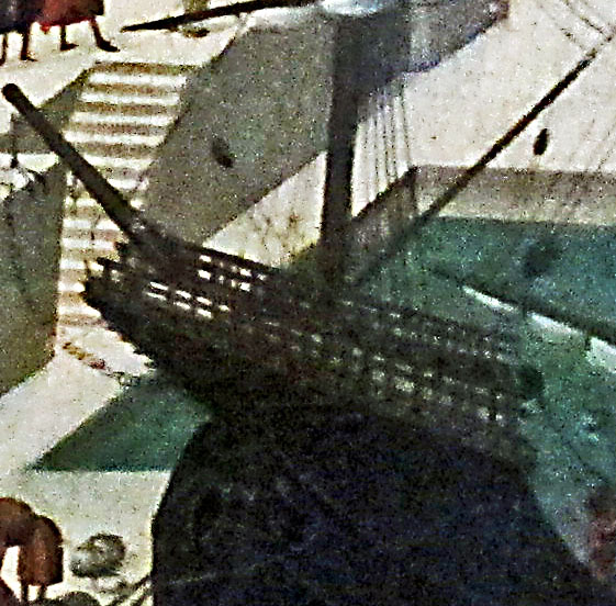
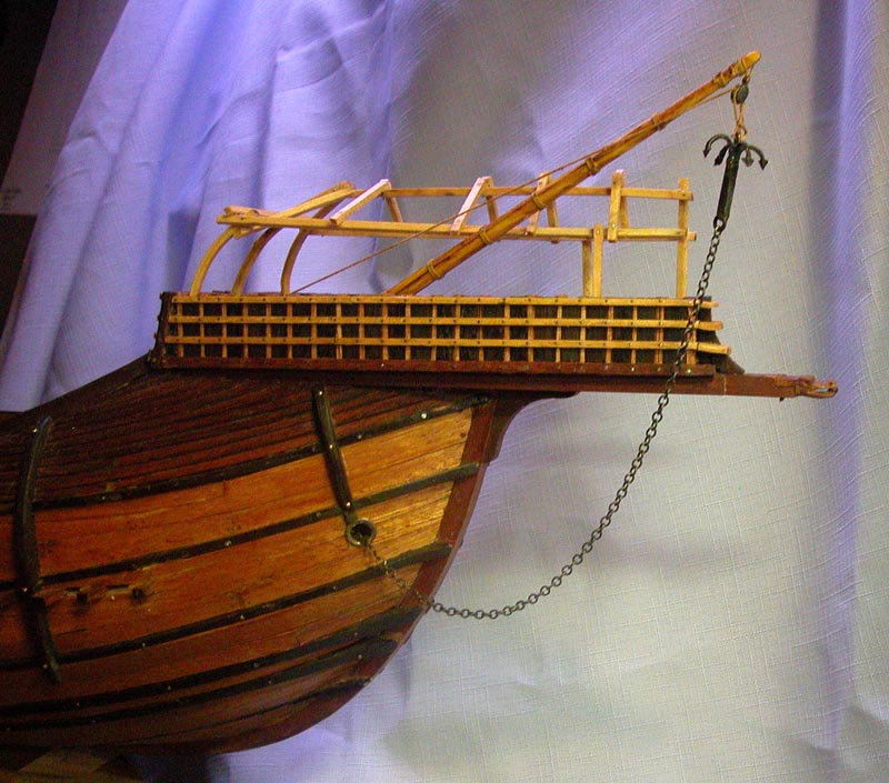
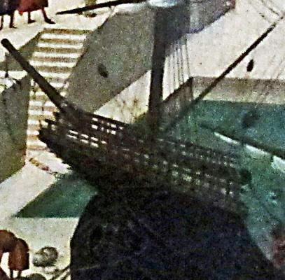
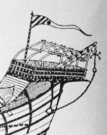
These show the grapnel hung from the bowsprit and the figurehead similar to that of the Gribshunden wreck. Dick

- 632 replies
-
- 19
-
-
Just a suggestion but putting the frames external to the plug as here in my longboat http://modelshipworld.com/index.php/topic/4496-usf-essex-by-woodrat-scale-1-64-fully-framed-from-takakjian-plans/?p=142797 allows you to edge glue the planking and fix the planks on the frames. The keelson ( if dromons had them) can be morticed to hold the frames and the keel fixed over the frames. Dick
-
Thanks, Steven. The new workshop is not fully set up but am starting to work again. I have a vague plan to do a reconstruction of that mysterious beast, the hulc (hulk, holk) once I rig the carrack. How is the dromon going? Cheers Dick
-
thanks, George. It's not that they kept records, they didn't. They kept secrets of shipbuilding which were handed down within the guilds. People were probably murdered to maintain these secrets . Cheers Dick
-
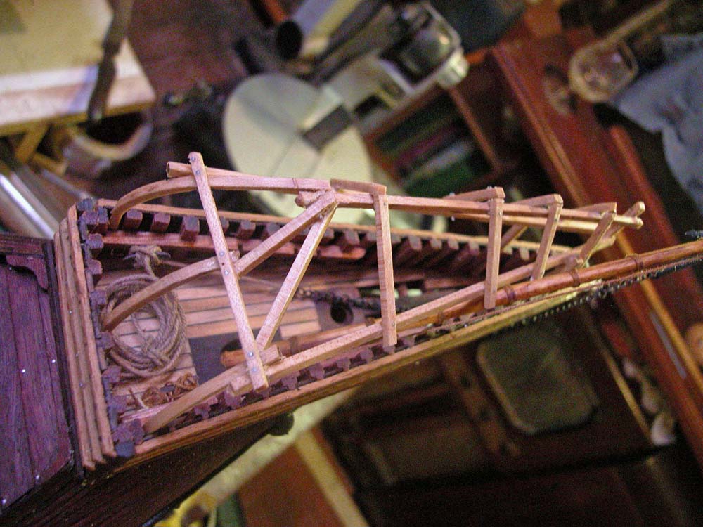
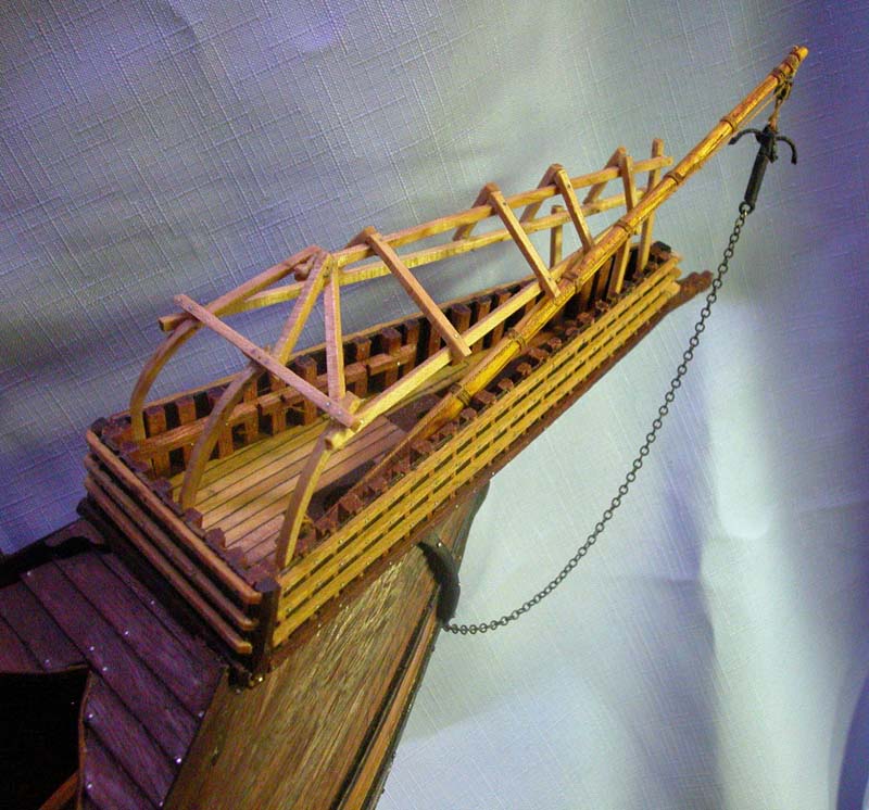
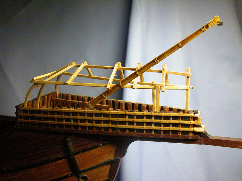
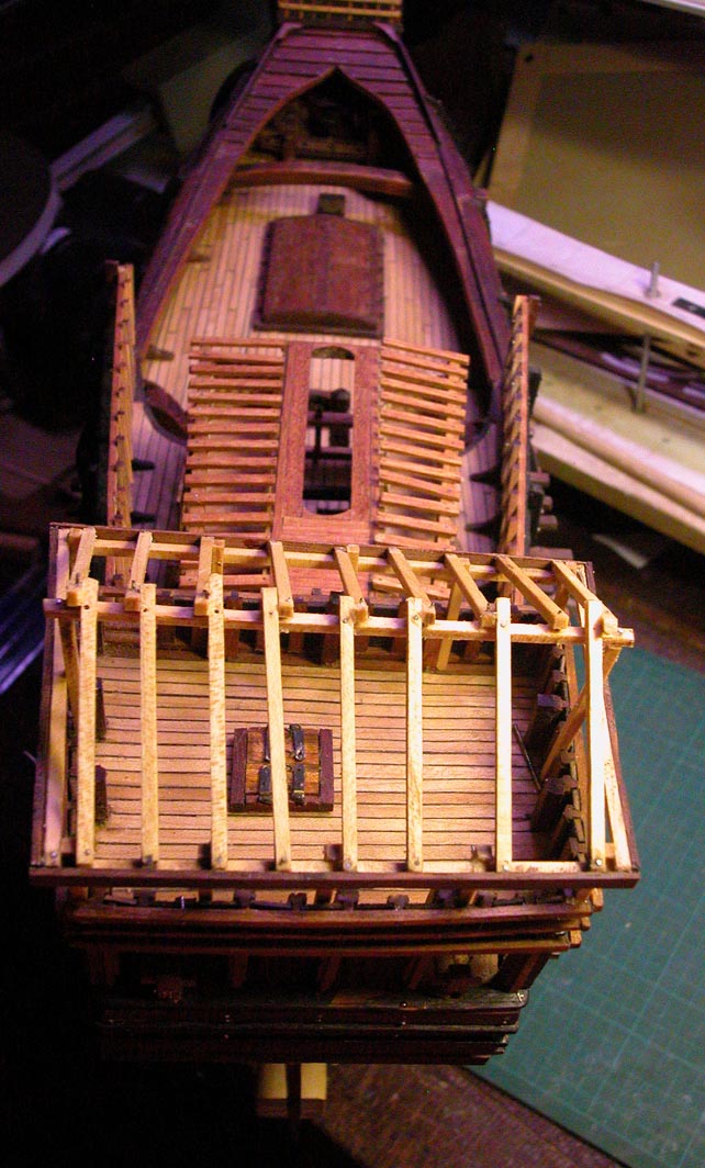
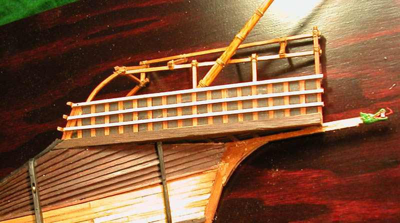
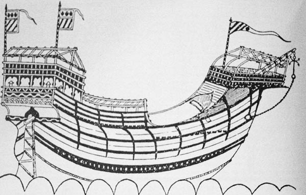
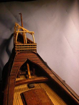
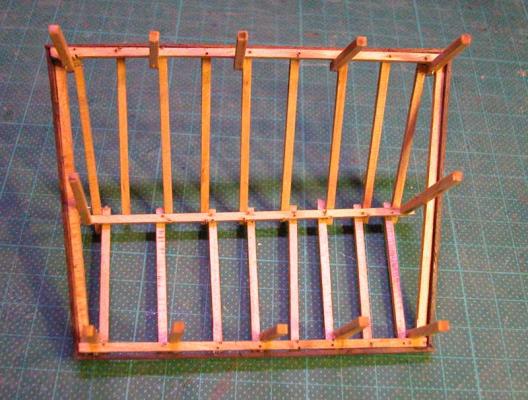
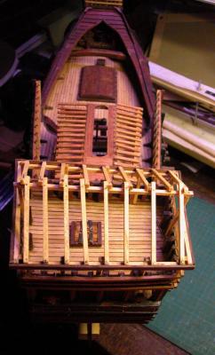
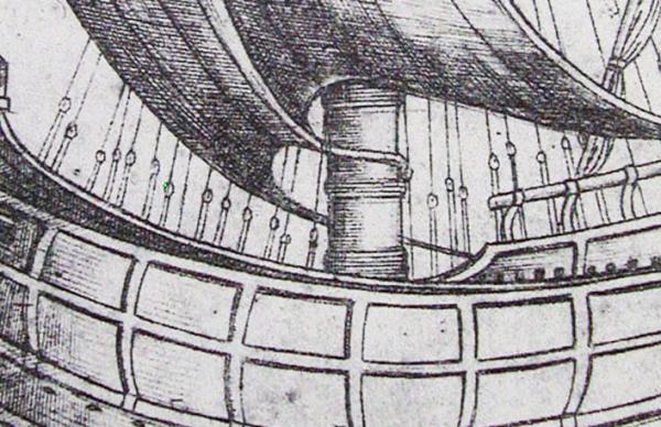
This is as close as I can get to how the forecastle is depicted in the original drawing. Note the asymmetry (foremast not yet stepped). The bowsprit sticks out over the starboard rail of the forecastle. Again, the carpentry is crude and appears temporary. the forecastle from aft. There were no crew quarters. They slept where they could find shelter. Hammocks were unknown.

- 632 replies
-
- 14
-
-
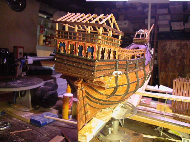
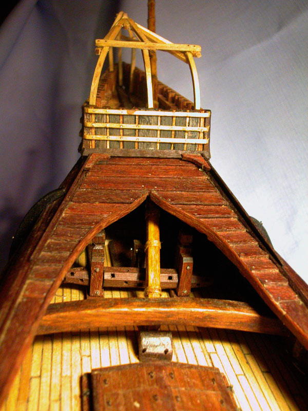
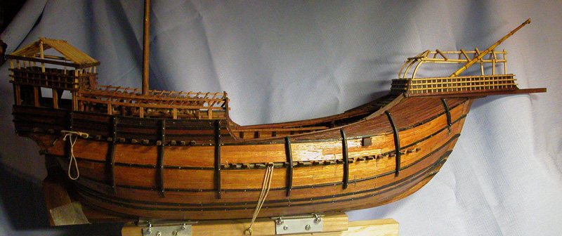
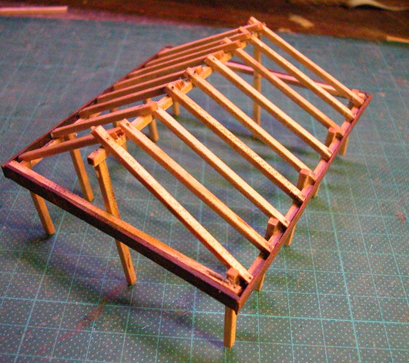
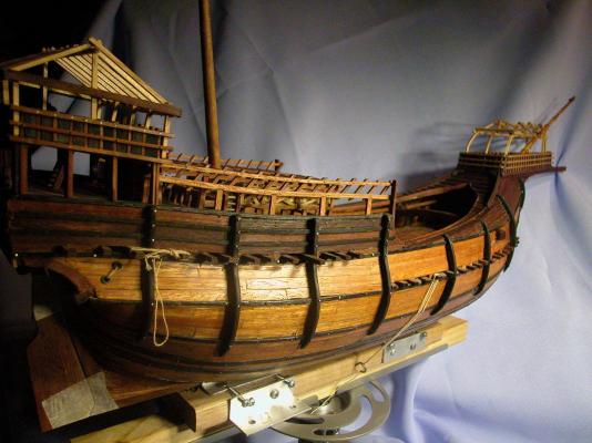
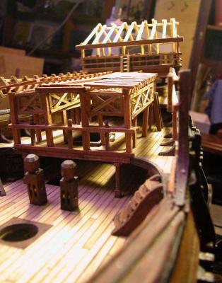
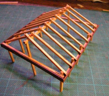
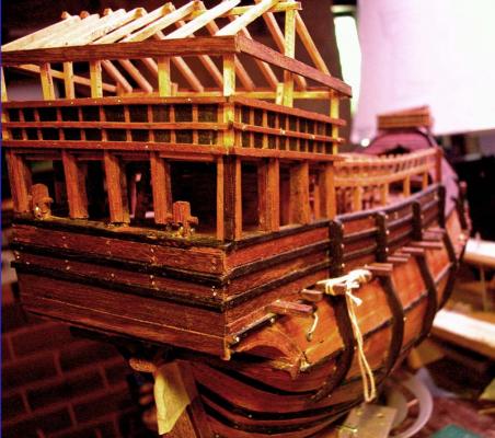
Sorry for the delay in posting. I have now completed the sterncastle including the somewhat jury-rigged appearance of the carpentry on the shelter itself (this is seen on the original Trombetta document and presumably indicates that the sterncastle shelter was temporary and easily disassembled or cut away in an emergency) I have provided some very basic accommodation or shelter for passengers on the quarterdeck which can be accessed by ladders. There is evidence from contemporary illustrations for such accommodation. Now to do the forecastle shelter which is more challenging as it is asymmetrical to accommodate the foremast. Dick
- 632 replies
-
- 12
-
-
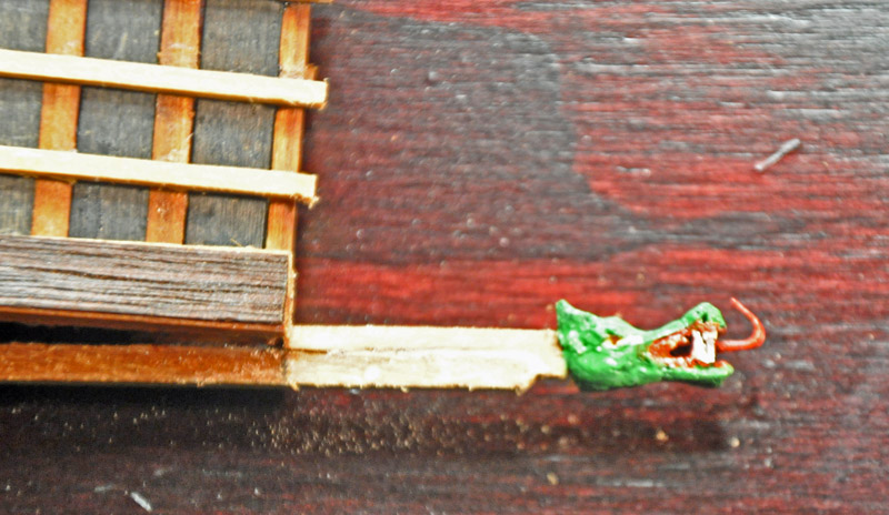
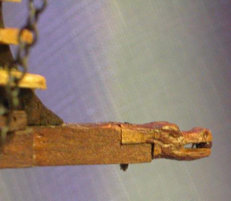
Thanks, Steven. This is a very good find! It matches some of the carrack figureheads seen in 15th century illustrations. I based my figurehead for the half-hull model on this sort of beast A similar beast may be made out on the trombetta illustration. Here is the figurehead for the Kraek vessel Cheers Merry Xmas Dick


-
The article by Salisbury has a diagram of the mast remnants. It is also found in the excellent monograph "The Good Ship" by Ian Friel. I cant reproduce here because of copyright. Dick
-
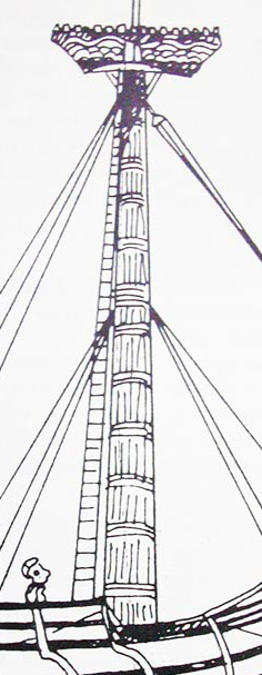
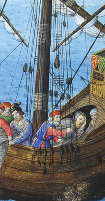
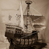
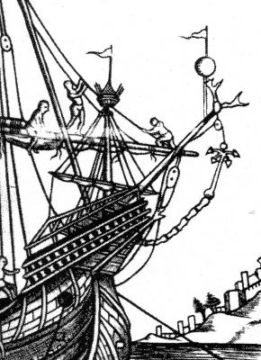
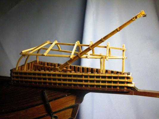
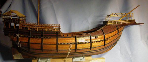
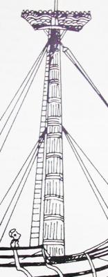
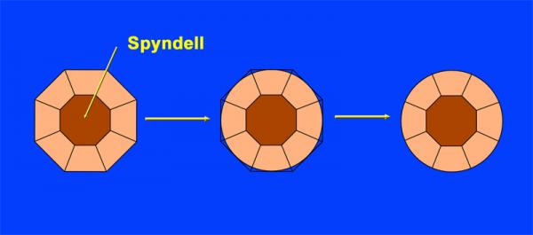
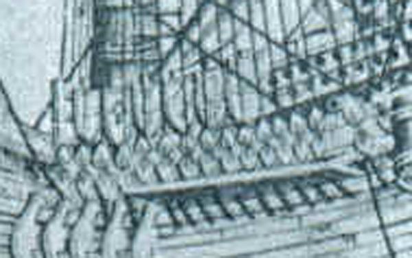
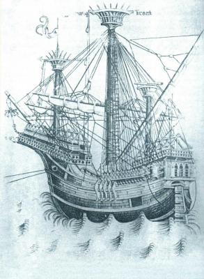
Masts in larger vessels of the middle ages were "made" masts. That is to say, made of several spars shaped and scarfed together and then surrounded by hemp wooldings usually nailed to the mast. This is seen well in this mid 15th century illustration from the Trombetta manuscript. Only smaller vessels had pole mainmasts made from a single spar. Foremasts and mizzen masts were usually single spars. Although maststeps commonly are preserved with the keel in shipwrecks, surviving masts are not usually found. An exception is the Woolwich ship found in 1912 (R.C. Anderson Mariner’s Mirror May 1959) and thought to be the Sovereign 600 tons of 1488 (W Salisbury MM 47 1961) . This wreck had a surviving 10 foot stump of mainmast still in its step. It was 1.32 metres in circumference. By my calculations, this would make it 42cm in diameter at its base. I have elected to attempt a "made" mast based on the Woolwich ship This will have a central large spar octagonal in shape (the spindle or spyndell) with 8 filling pieces surrunding it. Below deck level the mast would probably remained octagonal but would be rounded above deck level. Dick
- 632 replies
-
- 10
-
-
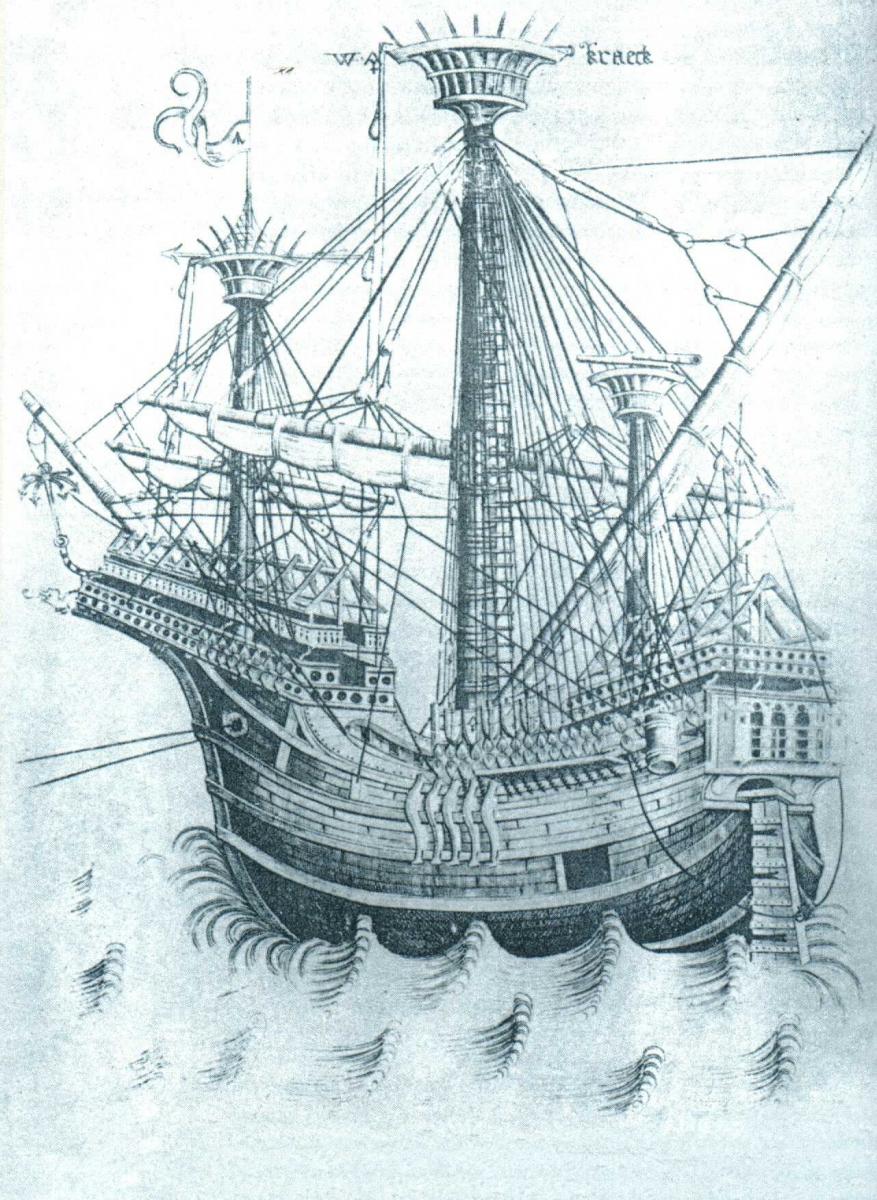
I think triangular deadeyes are correct but more likely to be found in northern europe as in the W A Kraeck . The Mediterranean practice seems more likely to have been pendants and blocks Some of these blocks were massive and elongated These are just my opinions. Certainly I would not criticise the choice of deadeyes. There would have been much regional variability Dick

-
I don't think deadeyes would be correct for this era, at least not the mediterranean. I will go with pendants and blocks as seem to be shown in Carpaccio. The wattling may be a good idea for some of the windbreaks of the quarterdeck accommodation. Great model Tadeusz, which plans did you use? dick
-
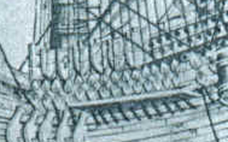
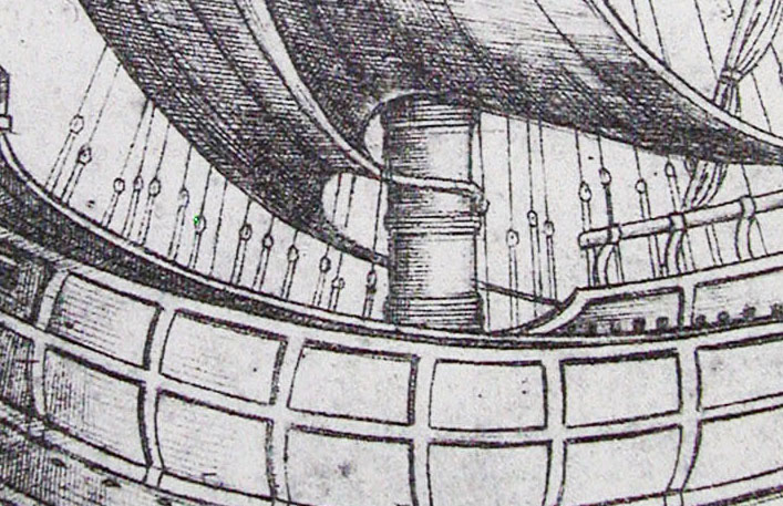
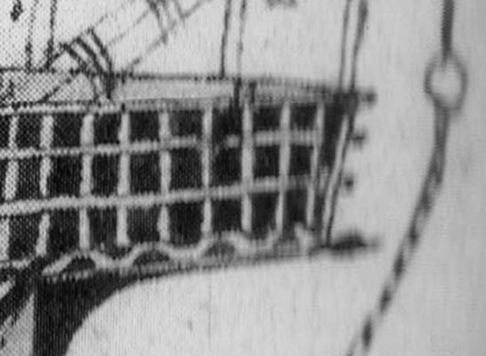
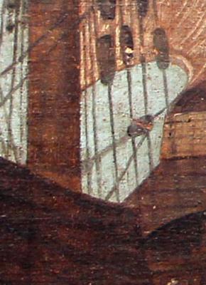
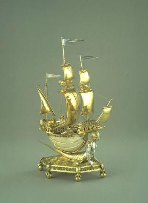
Where DO you find these things? I have not seen them afore. Some are clearly sketches of nefs used as table ornaments or salt cellars by the nobility. Often these were made of silver but sometimes combined with precious stones or even nautilus shells. Few of these nefs have survived to the modern era. "Burghley nef" by The original uploader was VAwebteam at English Wikipedia https://commons.wikimedia.org/wiki/File:Burghley_nef.jpg#/media/File:Burghley_nef.jpg The most detailed one seems to be a votive model. Of note is the presence of a "loading port" as seen in the famous "Kraeck" illustration of the flemish master W A. Very interesting! Note also the ventilation ports AND the apparent projecting beams at the level of the mainwales!!! As in the Trombetta illustration!!!
-
Thanks, David. I have not considered that. What is the mechanism? I am not a NRG member. Is that a requirement? Cheers. Dick