


AON
-
Posts
2,580 -
Joined
-
Last visited
Content Type
Profiles
Forums
Gallery
Events
Everything posted by AON
-
 Once I get my eyes adjusted I'll hopefully be able to spot those details again.
 -
thank you missed that detail inside the figure.
-
I have 1985 copy of The Anatomy of Nelson's Ships by C. Nepean Longridge. Page 188, second paragraph from the bottom refers to figure 119. There is no figure 119 .... there is a 118 then a 120. If anyone has an copy of this book that has figure 119 could you please scan it and send it to me. I will print it and insert it in my copy of the book. Thank you. Alan
-
I should have mentioned it is also in The Anatomy of Nelson's Ships. I've had my breakfast so the brain is starting to work.
-
Thank you all for the responses. My source : The elements ans Practice of Rigging and Seamanship - vol 1 - is dated 1794. This table suggests it is in ships of 100 guns down to sloops (found on pg 45) it is not mentioned again nor is it shown in any of the Plates diagrams of masts and yards for any size ship. (not that I can find this early in the morning)

-
I just discovered yesterday that there is a flying jib boom. It is not on many builds. Steels lists it for the 74 gun ship, but I've not seen it on any builds except the 50 gun HMS Leopard (1790). I've read an old post that states the flying jib boom and the jib boom are the same thing, and having seen it I know they are two different things. The flying jib boom protrudes beyond the jib boom, secured to the head of the jib boom with an iron clamp The heel of it rests against the bowsprit cap. I've no idea how that end is secured. I also have no idea if it is an optional boom extension, when it is added, or what determines it should be included. Seemingly only if a flying jib sail is wanted to be rigged... seems to be logical. Does anyone know more about this item: why, when, where used? Thank you in advance.
-
HMS Fly according to papers, she was in Antigua in January, notice of PRIZE published 5 March... still looking update: did a quick search through to July and no other mention of her
-
from the reliable Wikipedia: HMS FLY On 17 September 1801 Fly left Portsmouth as escort to a convoy for Newfoundland. She foundered and was lost with all hands off Cape Flattery, Newfoundland in January 1802.
-
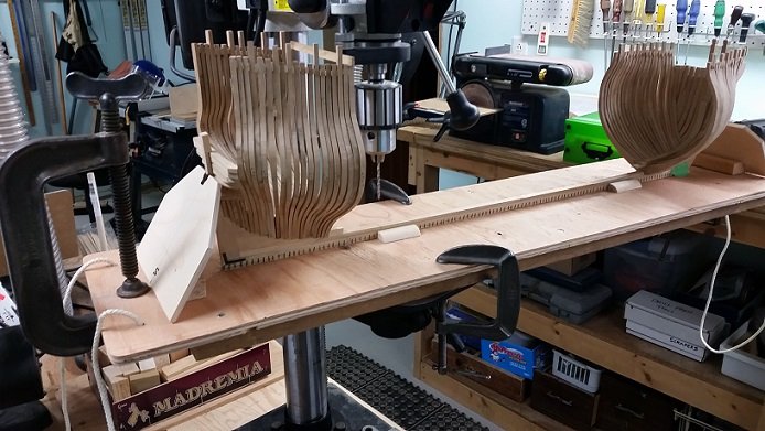
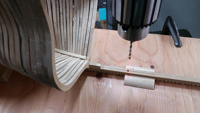
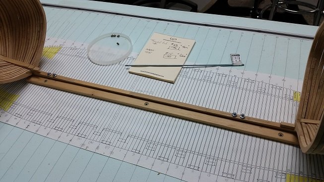
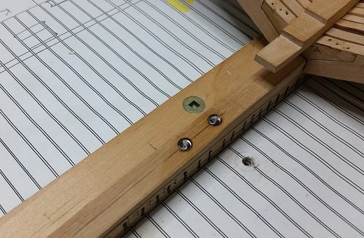
Mounted the model on the travelling base. Used a heavier clamp at one end as a counter balance as I made adjustments to align the drill bit with the mark then clamped it to the drill press base. Drilled the holes. #29 thru, #15 1/4" deep. Set it on the build table and drilled thru the table. Made up lengths of threaded rod, chased the threads after cutting the lengths (borrowed my son's tap and die set for this). Installed the helicoil inserts as described earlier. Now it sets up and cures. I left one of the original wooden clamping bars on the table as I can set the keel to it/align to it, and it holds the plan in place on the table.
-
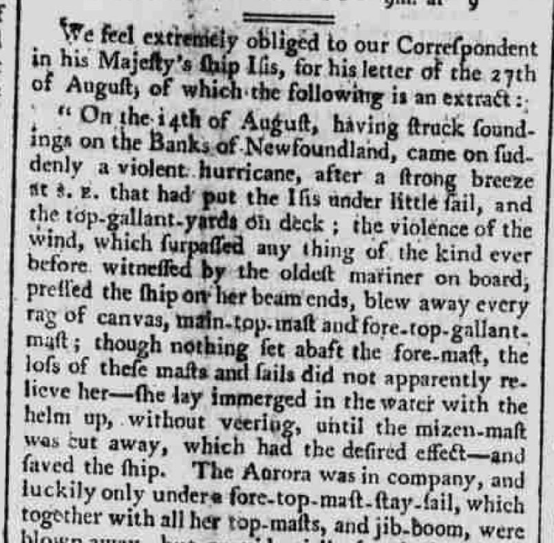
Surviving hurricane winds on the Grand Banks off Newfoundland (1802)
-
...and along the same train of thought... times were harder then. (1802)


-
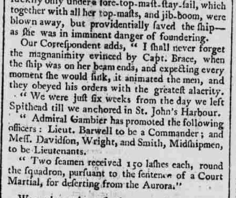
Life is like that, eventually you either are no longer needed or worse, outlast your usefulness (1802)

-
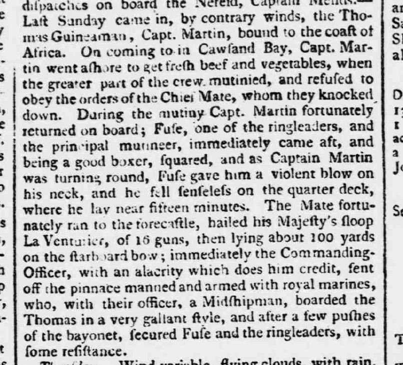
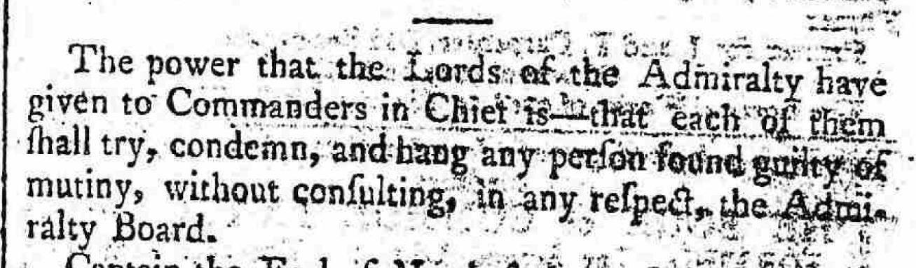
ARGH, there be a mutiny aboard her
-
Ah, nothing like a little scurvy to top off some surviving a lightening strike

-
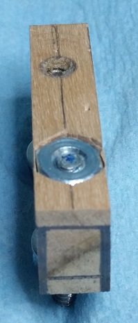
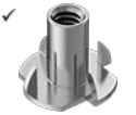
As a picture is worth a thousand words I thought I'd try to explain it another way. In the photo below I show the Helicoil thread insert (in a stepped hole) versus a hex nut (set in a customized pocket). I have also drawn in the rising wood (top), keel, and false keel (below) at the end of the block of wood. The hex nut and helicoil are buried in the rising wood. The hex nut is as thick as the rising wood so it necessitates the removal of a great deal more wood than the helicoil. In my mind it is cleaner and simpler. More rising wood is left in place. The frames glue to the rising wood... so it would be nice if some wood were there. The hex nut is entrapped and so cannot spin. With the tang removed from the helicoil it does not move. So both are equal in that sense. The hex nut has 3.6 threads and the helicoil has 7.
-
YIKES!!! (1801)
-
A book. It would be the worst selling book ever! I would think there are very few people willing to pay for such a thing. Wouldn't you rather just get it for free?
-
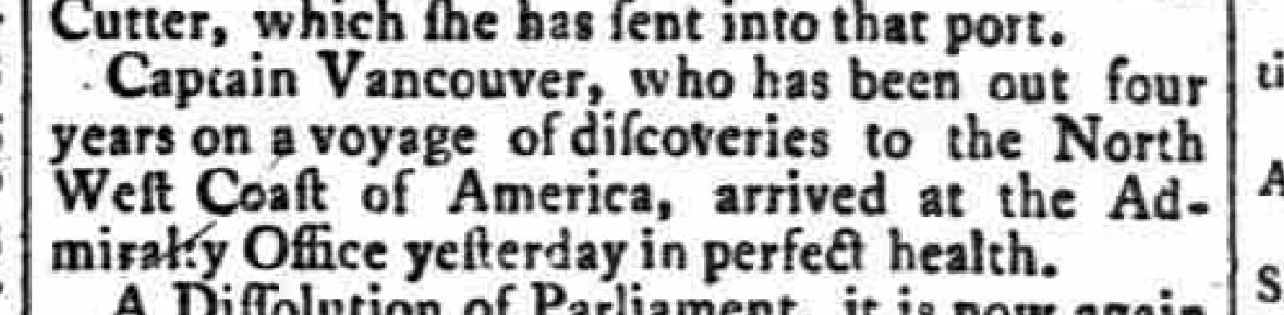
This one was mis-labelled as 7 July 1801 but when opened it was realized to be 24 Sept 1795 It has a special meaning for me, as I had spent 5 summers on Vancouver Island, and earned my sailing and pulling cox'n papers in my third summer out their.
-
Thank you Mike. I had looked at these and thought they were quite large a barrel diameter and then also to the OD of the cutting thread, and in some cases the length. I was hoping to minimize the material (wood) removal. My test worked, but I will need to remove the "tang" as if you continue to turn the rod after it contacts the tang the insert threads out of the hole. Of course there will eventually be a frame covering the hole so the rod will only thread in so far and have to stop. In my application, I used a somewhat backwards installation as I cannot cut the proper size thread in the wood (as I am a cheap ol' coote). Normally they feed in the same side as the screw or rod, but mine in in the opposite side to create the retaining shelf for clamping.
-
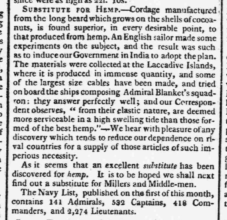
a substitution for HEMP cordage is discovered..... and the list of officers gets even more inflated. (1801)
-
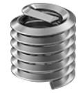
Above is a threaded insert (aka helicoil threaded insert) Below is a blind nut. I think you are referring to the blind nut with the flange and spikes that have a much larger diameter cylinder (with the threads inside) than the OD of the threaded insert, requiring a larger hole and length removing more wood than I prefer. The flange on the #6-32 blind nut is too large for the width of my keel and would require filing. The thickness of the flange requires a spotface in the keel to get the top flush or buried. The spikes are just a pain in the behind. I was looking for something cleaner than the flanged/spiked blind nut, and cleaner than a standard hex nut that would need to be filed across flats to fit in a pocket that would need to be chiselled out of the top of the keel. I am attempting something different. If this does not work I will resort to the hex nut, that is quite functional, but ugly (and, yes, I know it will be hidden). And you, sir, are anything but thick.
-
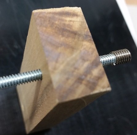
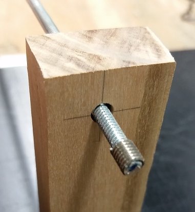
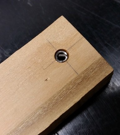
TESTING the stainless steel #6-32 helicoil thread insert for mounting my build to the table and eventually the display mounting board. FYI: #6 refers to the screw thread diameter; 32 means 32 threads per inch. I learnt long ago that the full strength of a thread is developed in the first fully engaged 5 threads, everything after that is safety factor. When I ordered mine I made sure it was long enough to have at least 5 full threads... mine has 7. I decided to drill and thread a hole in an attempt to assist the insert into feeding into the wood. First I drilled a 9/64 inch (0.1406 inch) hole for a #8-32 tap. Now a #8-32 thread is a slightly smaller diameter than the outside diameter (OD) of the insert but I thought as it was going into wood I might be able to ease it in so it followed the 8-32 and cut it's own threads a wee bit deeper. That did not happen as the "wire" is very slim and so it deformed. I then tried feeding it in with it on the threaded rod and that did not work. If I had spent an extra $40 for the correct tap and proper holder for the insert I likely would have been successful, but I didn't think the extra expense was worth it for 4 holes. Luckily I purchased 10 inserts and only need 4 for the job. So next I decided to try by drilling a stepped hole. First I used a #29 drill bit which is slightly larger than the rod OD at 0.136 versus 0.132 inches and drilled through the wood. So the rod slips thru easily. Second I used a #15 drill bit and drilled down 1/4". The #15 bit is 0.180 inch diameter and the insert is 0.1785 inch OD. The next smaller bit would be too small (#16 at 0.177 inch). This created a step or shelf that the insert rests on when placed in the hole. Although advertised as 0.276 inches tall the insert is actually 0.232 inches tall so a 1/4" (0.25 inch) deep hole puts it just below the surface. My keel assembly is almost 1/2" tall. I then inserted the threaded rod and rub some good old petroleum jelly (Vaseline) on the OD of the rod threads. Then I screwed the insert onto the end of the rod. Then I cleaned up a bit of the petroleum jelly that got pushed out of the threads by the insert. I applied a thick two part epoxy onto the OD of the insert. The petroleum jelly is supposed to keep the epoxy from migrating through the coil of the wire and gluing the threaded rod to the insert. I then pulled the rod back into the wood block to draw the insert in and up to the shelf or step. I let that set for a while and eventually removed the threaded rod. Now it is curing. Later today or more likely tomorrow morning I will test that it is holding, does not spin. I will apply reasonable torque (a wee bit over snug) for the small thread. The end of the stainless steel threaded insert has a tang blocking the hole. This is used with the proper insertion tool to help thread the coil into a threaded hole. It is meant to be broken off after the item is installed. If what I just did works, I think I will leave it on as a stopper for the threaded rod. Below are some photos.
-
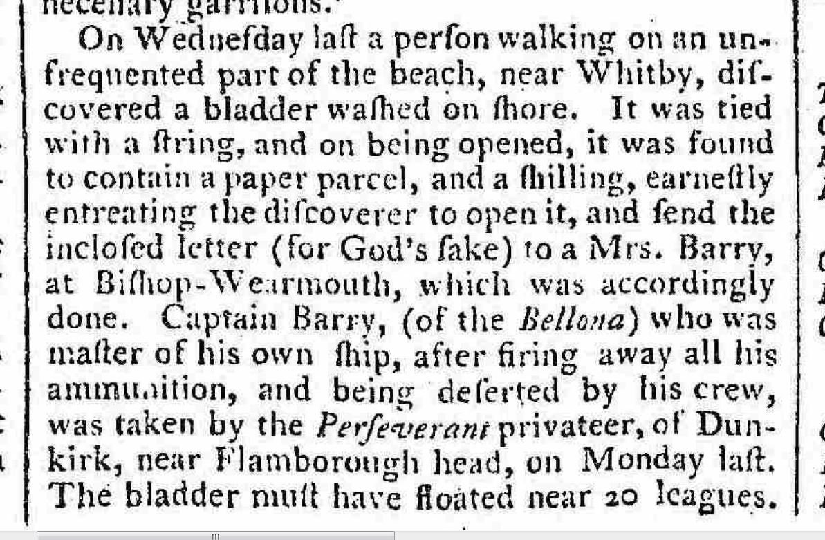
Prior to e-mail was snail mail before that was the proverbial message in a bottle (AND NOW THE SONG IS STUCK IN MY HEAD)
-
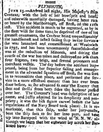
What is interesting about this article is the figure carved was said to be the last prior to the cut backs that resulted in less ornamental, and more importantly, less costly carvings. 23 June 1800
-
(1800) punishment fitting the crime? Ouch. I guess it made others think twice.

