HOLIDAY DONATION DRIVE - SUPPORT MSW - DO YOUR PART TO KEEP THIS GREAT FORUM GOING! (89 donations so far out of 49,000 members - C'mon guys!)
×


AON
-
Posts
2,866 -
Joined
-
Last visited
Content Type
Profiles
Forums
Gallery
Events
Everything posted by AON
-
 Thank you Druxey. I'm guessing it is four pair... but then wonder why Vanguard kit has six? This may never have an answer. I should double check museum models on line just to feel better about it all.
 -
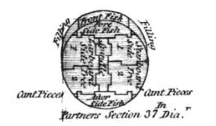
I am presently trying to determine the number of shroud slots in a 3rd rate main mast platform. Steels table reads 4 pair but 12 deadeyes. All details below that support 4 pair. Were the other 4 deadeyes spares? Vanguard models show 6 pair. Bellona (the book) has 5 pair. Taking a break.
-
To be more specific TFFM section 15 shows concave as are Greg's accompanying 3D images. Historic ship models page 223 show the same. TAONS (HMS Victory) page 174 shows tapered. Did Mr Longridge simplify it? I'll chew on it a bit. Would David and Greg lead me off course? I think not.
-
Some references showed scooped while others seemed to be a simple taper. Presently they are tapered.
-
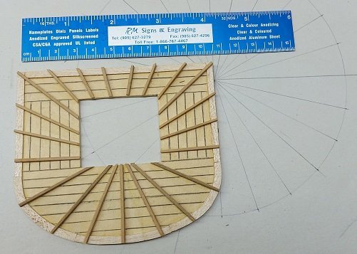
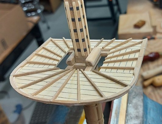
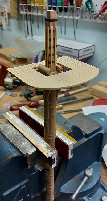
Got a little bit more done to the platform. I've a couple more pieces and some holes to add before this small part can be called done. (it is only dry fitted to the trees to see how she looks in place)
-
Took the TREES apart to shape them then reassembled. Removed the BIBS, remade and refitted them. TREES installed and battens installed. Made the TOP (platform) that sits on the trees. Three layers of 1/32" glued cross grain. Planks laid out and scored with a knife, highlighted the joint with a pencil, then sanded. Underside scored to show the different overlap. More work to be done to the TOP before it is fitted permanently.
-
I understand what you are saying about the hoops. It was an effort to try to keep them straight and level and evenly spaced... I am not saying I was successful. I thought if it should look like kaka I paint the space between the hoops (under the rope) as camouflage. Worst case... off it comes. I guess I should wrap some twine between a couple and see the "damage" before I get further ahead of myself! Tapers... yes. Angle... very slight. Thank you.
-
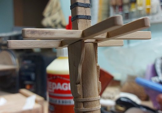
Been busy putting things on, taking them off, putting them back on... normal stuff. Removed the bibs, added the wooden hoops for the woodling ropes, added the metal hoops above the stops, made the cross/trestle tree assembly, put the bibs back on. I sanded the wooden hoops so they are presentable. Made my bolsters but have not added them to the tree assembly as yet. Need to add other metal hoops, battens, and build the tree platform.
-
Looking darned good. If it were any of the sea cadets I knew the sweeps would be all wonkey! Still waiting to see how the rudder yoke connects to the tiller. I know how it worked on the whalers but they had a mizzen mast to pivot on.
- 433 replies
-
- 3
-

-
- open boat
- small boat
- (and 1 more)
-
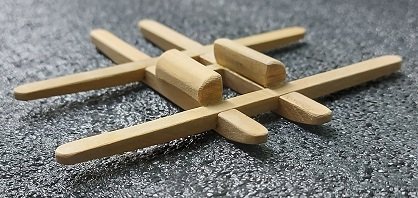
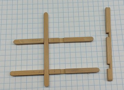
Thank you Druxey. We learn by our mistakes. Easily remedied...but I will have a Trestle Tree made to guide me when I correct this.
-
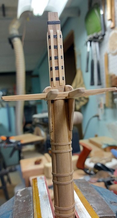
Some update pics. I've yet to add the Woolding Hoops and the eight Battens above the stops.
-
The sweeps on the whalers and cutters I am familiar with were exactly that and very light, made of ash.
- 433 replies
-
- 4
-
-
- open boat
- small boat
- (and 1 more)
-
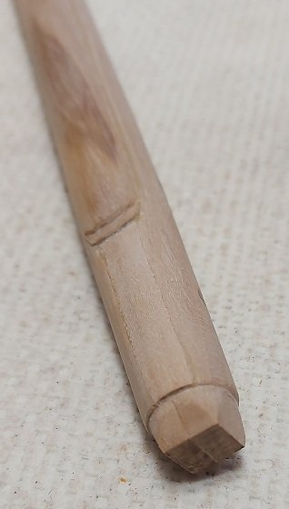
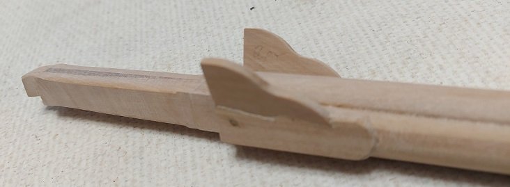
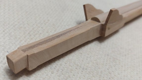
Using a steady is the only way I know of to keep it straight. I have the seats (flats) cut in for the fish and cheeks. Started working on the front cheek.
-
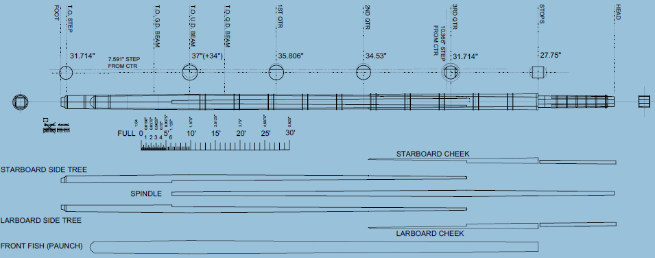
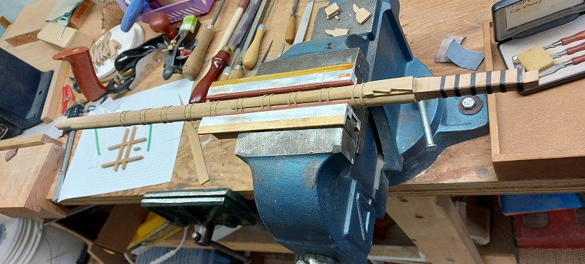
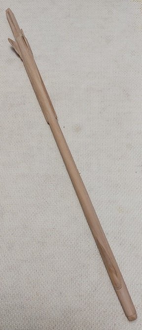
Three piece main mast turned. Marking off the extents of the flats for the cheeks and fish.
-
Had you considered mounting her suspended from davits? 😇
- 433 replies
-
- 5
-
-
- open boat
- small boat
- (and 1 more)
-
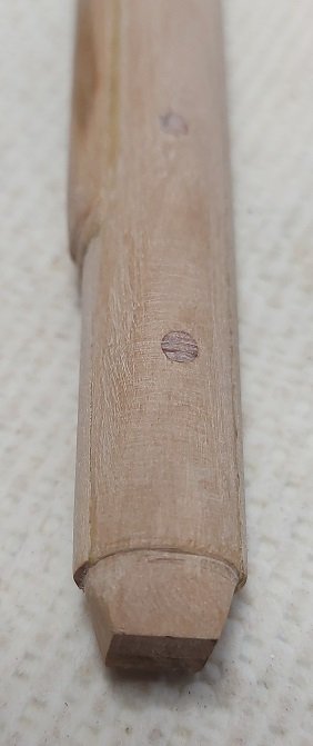
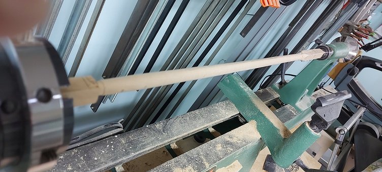
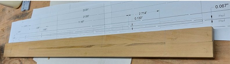
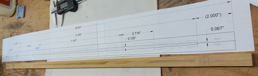
Made my transfer batten from a piece of plaster wall lath (hemlock strip). Marked off each quarter location and step where the diameter dimensions were indicated. I was concerned my three pieced glued mast might pull apart on the lathe during turning so I marked off where the hoops and woolding bands are located and drilled #31 hole on centre at each location through the port/starboard sides and pinned through each hole with a 1/8" dowel. I lightly crimp notched the surface of the dowel with the grooves on my pliers, applied wood glue, then tapped it through the hole and cut it flush. Belts and braces. This might not have been necessary but I'd rather not find out. Once the woolding ropes are wound on the lower pins will be hidden. The upper pins will be under the cheeks so they won't be visible either. Now we let that dry and cure. Turning hopefully tomorrow.
-
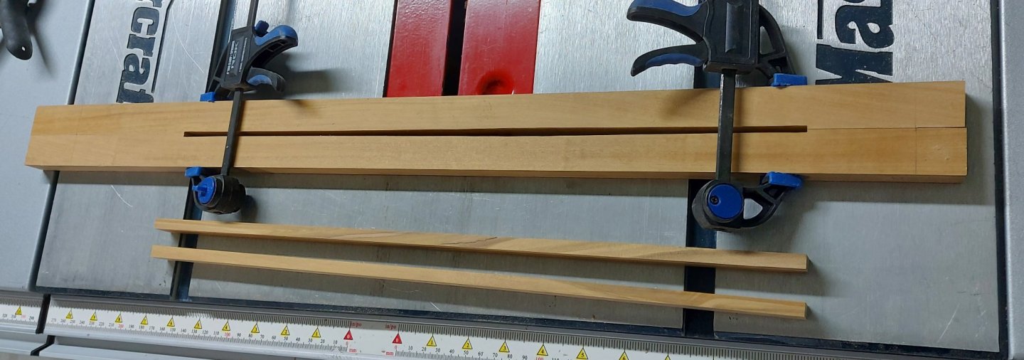
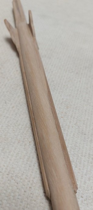
Sanded the spindle to shape. Glued up the three pieces (side trees and spindle) and left them clamped overnight. Trimmed the excess off the sides of the tree blanks and put these pieces aside to be used for the aft fish and cheeks. Now being square I can shave off the four corners a bit and it will be ready to turn down to size.... maybe tomorrow or Wednesday. I've prepared another sheet with location and diameter info that will be transferred to a batten which can be held against the part on the lathe to help relocate these critical spots once the pencil marks have be cut away. I will leave the square ends untouched to help me relocate the four sides to create the flats for the fore and aft fish and side cheeks. Hopefully I've thought this through adequately.
-
For me the 27ft Whalers were single banked while the 32ft Cutters were double banked.
- 433 replies
-
- 6
-
-
- open boat
- small boat
- (and 1 more)
-
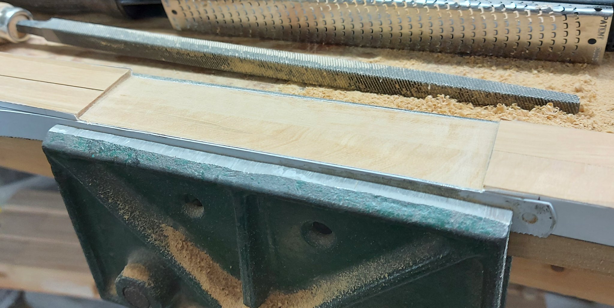
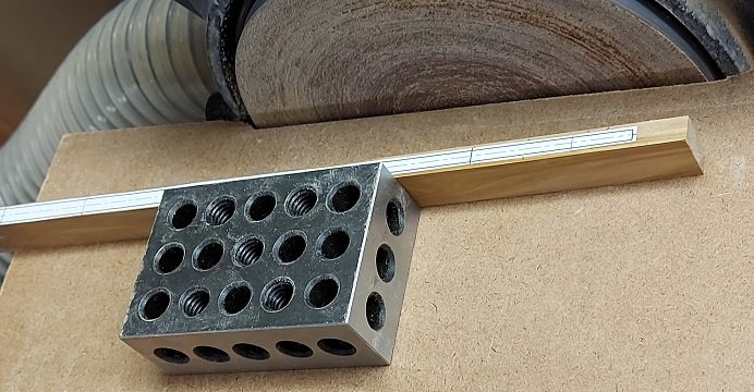
Extremely short frames progress report: I am presently working on square frames 13Aft to 11Aft having made up a batch of new blanks. As the nice weather is upon us I will find myself drawn outside to soak up some vitamin D from the glorious sun. I will be making another attempt at my figure head while out there. Third time is the charm??? Always eager to attempt something new, I spent a considerable amount of time studying the construction of "made masts". My ship would have had them for all the lower masts. The problem with these are that all the pieces that make up a "made mast" are hidden from view so the question that begs to be answered is "why bother?". My answer seems to be "for the challenge of it". I'll try one to start. My bowsprit is already done so it was spared the trial. I've drawn up a simplified version of the Main Mast and will attempt it first. I've ripped and planed two blank pieces for the side trees and one for the spindle (and one spare). I've completed the notching of the side trees to accept the spindle by double side taping the two pieces together with the centre of each facing upwards. I rubber cemented my cutout pattern to the outsides of each and double side taped two hacksaw blades to the pattern with the non-tooth edge lined up to the edge of the cutout on the pattern to act as a stop guide when removing the waste. I removed the waste from the spindle notch with a wood rasp and files. Presently the spindle blank ready to be shaped. I rubber cemented my template to one side and will use my 90° setup block as a backer to hold it dead parallel to the bench disk sander on the rest plate. This will take some patience to assure the fit is proper... even though no one will see 80% of it as it will be inside the mast! The lower portion will be hidden by the front and rear fish pieces. Wish me luck.