

AON
-
Posts
2,580 -
Joined
-
Last visited
Content Type
Profiles
Forums
Gallery
Events
Everything posted by AON
-
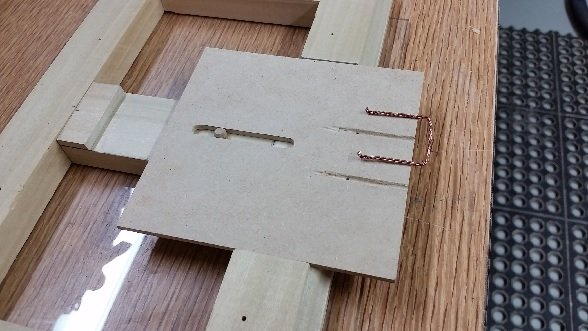
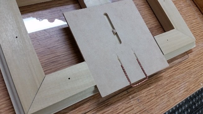
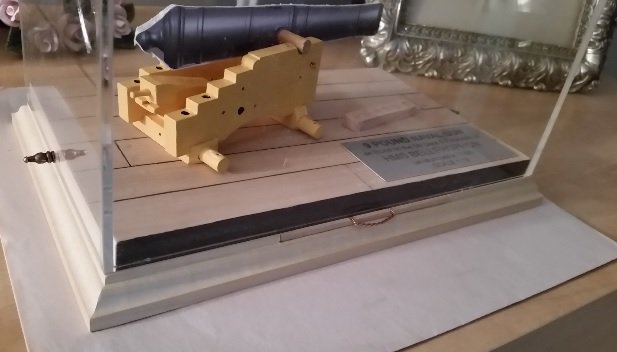
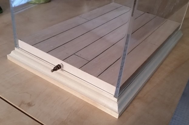
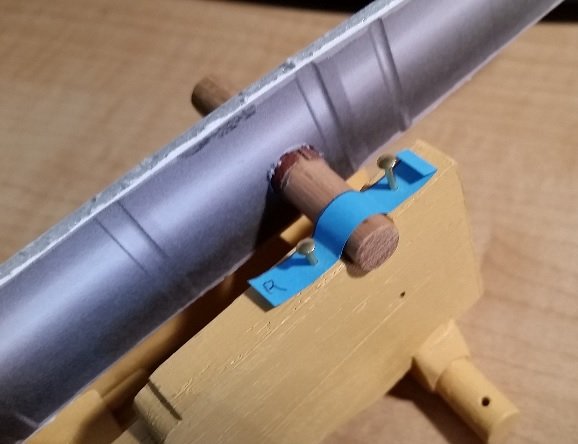
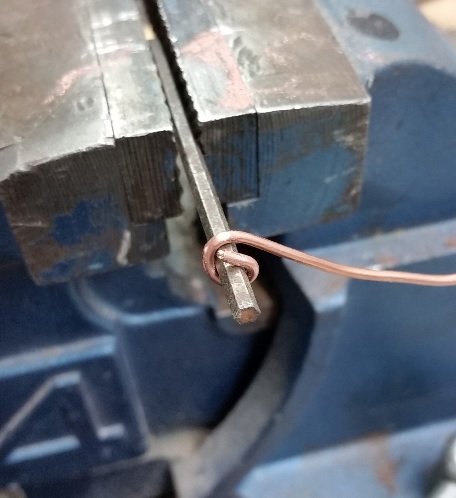
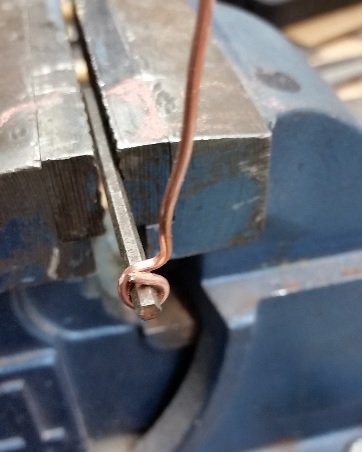
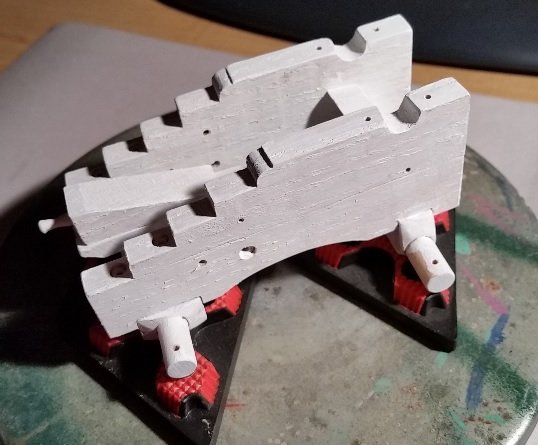
 Then I started working on the sliding information tray. I made a support bridge piece between the frames, marked the depth, wood rasped and then sanded to the marks. Drilled and inserted the stopper dowel. I didn't get any photos of it until the final assembly. Marked the location, depth and width on the front frame piece then I cut it down. The sliding "tray" is a piece of MDF (medium density fiberboard) wide enough for the nameplate and deep enough to have a slotted hole to encapsulate the locking pin in a slotted hole. The pull out handle is made of three strands of 0.031" copper wire twisted together to look like rope. One end of the group of wires was clamped in the vise and the other end in the chuck of my variable speed drill. I ran the drill to twist the wires until I had the look I wanted. The wire was bent and the fiberboard was grooved for the wire to sit into, below the surface so the nameplate would sit flat (no bump). As an added precaution the ends of the wire were bent 90° downwards to fit into holes drilled at the end of each groove so when pulling on the wire it has additional holding power to the MDF. This was assembled and glued together. Then the tray was assembled to the sub-base and tested.
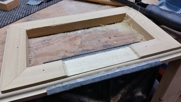

- 125 replies
-
- 11
-

-
- 9 pound naval cannon
- 3d cannon barrel
- (and 1 more)
-
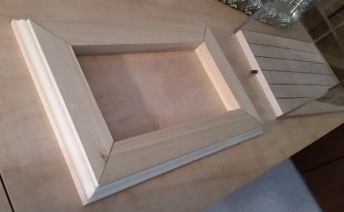
Had to go get my mitre saw from my son (he used it to build his garage) and cut the 45° mitres. Dry fitted them under the mounting board and case and made adjustments to get the "shelf" closer to the outer edge of the case. Then I sanded it down to the mark. Double checked and finally glued and clamped the pieces together.
- 125 replies
-
- 7
-
-
- 9 pound naval cannon
- 3d cannon barrel
- (and 1 more)
-
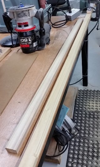
Worked on the sub-base frame. Practised routering on a piece of scrap to determine which profile was best out of three I had picked out. Decided on a 5/32" Roman Ogee profile. Took my length of 34" x 1-1/2" Poplar and with a 4 foot piece to ride on in behind it so the router didn't rock I cut the profile.

- 125 replies
-
- 5
-
-
- 9 pound naval cannon
- 3d cannon barrel
- (and 1 more)
-
Okay. No one asked. I had transposed the year of launch... 1786 was written and then engraved as 1768. Really dumb... my dyslexia exposed to the world.
- 125 replies
-
- 2
-
-
- 9 pound naval cannon
- 3d cannon barrel
- (and 1 more)
-
I am afraid if it was my mistake he would not accept any fault (or off any discount to the price) Ship Modeling from Stem to Stern by Milton Roth, pg 125 mention deck treenails. Historic Ship Models by Wolfram zu Mondfeld, pg 98 mentions deck treenails. He states "Please note: on iron framed ships - that is, after 1850 - no treenails or nails should be visable, but the wooden plugs covering the fixed bolts would be and would appear similar to treenails with a cross instead of an end grain." TFFM Vol 3 by Greg Herbert, Pg 157 mentions deck treenails. (funnily the other volumes of TFFM by David Antscherl does not mention treenails at all that I can find". I expect to see him on the 18th at our club meeting and will ask). I confess to not know any more than I read. Do you have a source of this info Druxey? BTW - I did find an error... of my doing.
- 125 replies
-
- 2
-
-
- 9 pound naval cannon
- 3d cannon barrel
- (and 1 more)
-
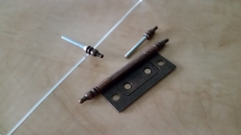
Sanded to two skewed short ends of the plywood mounting plate square and ironed on the maple edge trim. Using a #34 drill and my Dremel I carefully drilled a shallow pocket into the short end through the clear acrylic case. After removing the case I drilled the hole deeper for the pin. The pin was fitted to the hole and got stuck! As I pulled to remove it the ornamental cap popped off to reveal a perfect coned end. I decided this was the end I wanted exposed and the cap should go on the other end. It would not hold. I needed to press grooves (knurl like) onto the end to expand the diameter so it would grip and then tapped it on with my soft rubber mallet. Cleaned out the hole a bit and it is now a nice snug fit. Went to take the cap off the end of the other pin and found they used more glue on that one. Buggered the pin in my attempt to disassemble it. Thank goodness they sell hinges in pairs. I was able to get one of that pair apart and now have two good pins. The case fits well and the pins hold it all together! Tomorrow I hope to router some pieces for the sub-base and assemble it.

- 125 replies
-
- 3
-
-
- 9 pound naval cannon
- 3d cannon barrel
- (and 1 more)
-
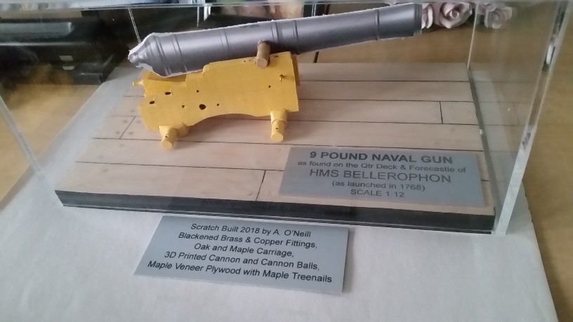
Picked up the nameplates today from our local trophy shop. Should have had them yesterday but they spelt NAVAL incorrectly (NAVEL). I could only laugh. They knocked $10 off the price so try as I might I couldn't find another mistake. I decided to go with laser engraved aluminium. It is clean, scratch resistant, professional looking and easy to read. I also decided to only mount the one on the deck as it looked to "busy" or cluttered. The other will be on a sliding pull out information tray or board just below the mounting plate and glass... yet one more thing learned at our last club meeting.
- 125 replies
-
- 5
-
-
- 9 pound naval cannon
- 3d cannon barrel
- (and 1 more)
-
All metal pieces are made and need to be blackened. The clear acrylic display case cover and my mounting plate were picked up today. The case looks wonderful but the fit is questionable. The case fits very well to the long sides but is too sloppy (too large a gap) on the short sides. This is likely my fault for not sanding the ends perfectly square to start with. The clearance measures 0.108" (2.7mm) whereas on the long sides it is 0.0005" (0.01mm). My solution is to sand both short ends square (as these are slightly out of square) and apply a 1/32" (0.8mm) maple wood veneer over the end to decrease the gap and snug up the fit with the acrylic cover. I should probably do the long sides also so the cut edges look finished. Went out and bought a $4 pair of door hinges. Cut one in half and took the pin halves out. I will use these as the locking pins for the acrylic cover. This pin will keep the cover from popping off if the display case is picked up by the cover. Thank goodness I went to last months club meeting to learn this pinning trick.
- 125 replies
-
- 5
-
-
- 9 pound naval cannon
- 3d cannon barrel
- (and 1 more)
-
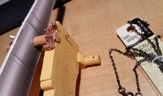
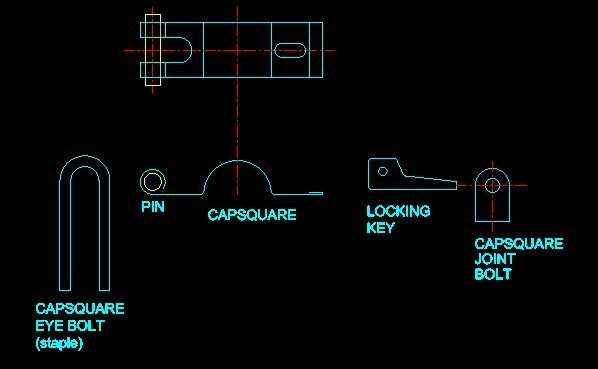
The CAPSQUARE JOINT BOLT was made out of plate, cut and filed to fit the slot in the Capsquare, and a hole drilled through to accommodate the Locking Key. The chain was purchased from Michael's, a local craft store in St. Catharines, Ontario (a 20 minute drive). It is from an 18" long black jewellery necklace collar. The Locking Key was made twice. I didn't like the first attempt and so, after sleeping on it, I made a more proper Locking Key. My copper plate material was too thin so I folded it over to get double the thickness, filed it to shape and drilled the hole to which the chain will attach.
- 125 replies
-
- 6
-
-
- 9 pound naval cannon
- 3d cannon barrel
- (and 1 more)
-
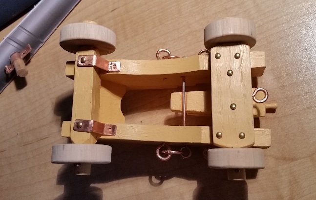
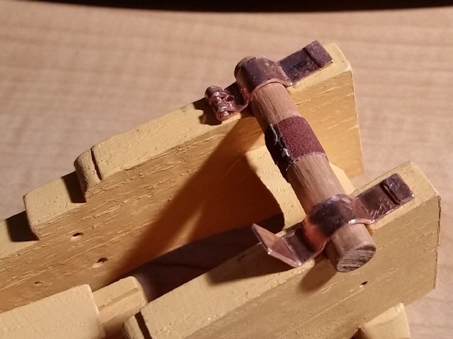
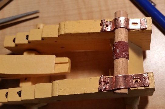
All these pieces were dry fitted to the carriage to give me a feel for the final look... and I like it so far. Two eye shafts needed adjustment so the eye sat properly. The simulated bolt heads are solid brass 1/2" x 18 gauge escutcheon pins bought at the local Canadian Tire store, hardware section. I cut the length short to about 1/8" and intend to glue these in place after blackening. I need to drill two new holes for the Fore Axletree Stays and the two missing holes for the Capsquare Locking Key Chain Rings.

- 125 replies
-
- 3
-
-
- 9 pound naval cannon
- 3d cannon barrel
- (and 1 more)
-
The next item to make was the CAPSQUARE using yet another flattened out copper tube material and new paper templates. The plates required a number of attempts at bending. The slot at the hinged end was cut with my Dremel tool and cutoff disk, then opened with a drill bit to fit the CAPSQUARE EYEBOLT (a simple piece of wire with a bent U at one end to make a staple). The hinge pin was then roll/clamped in place. My second and third Capsquare turned into scrap and so there was a fourth before it was done. Finally the Capsquare Joint Bolt slots were drilled and filed.
- 125 replies
-
- 6
-
-
- 9 pound naval cannon
- 3d cannon barrel
- (and 1 more)
-
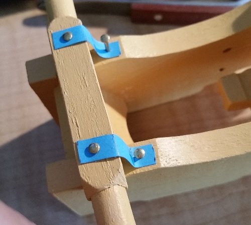
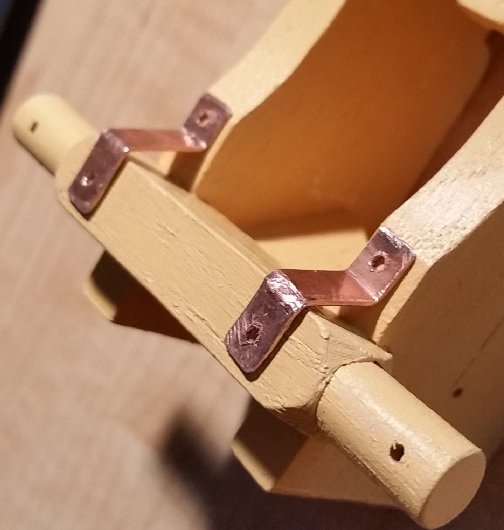
The FORE AXLETREE STAY was made of copper plate. The actual plate measures about 3/8" (9.5mm) thick or 0.04" (1mm) to scale. After hunting around my workshop I found some copper water tube that had a wall thickness of 0.032"... close enough! I needed to slice it open with a hacksaw, and flatten it out with a hammer on the anvil to make the plate. I started by making a paper template to fit on the model to determine the lengths required. Then cut it to size with a cut off disc on my Dremel tool, filed off the burrs, bent and drilled holes in the Stays.
- 125 replies
-
- 8
-
-
- 9 pound naval cannon
- 3d cannon barrel
- (and 1 more)
-
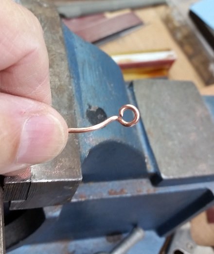
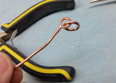
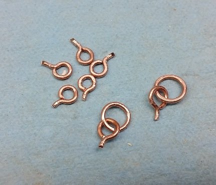
Now was the time to tackle the fittings. There are a number of eyebolts and a couple with rings: Train Tackle Eye, Gun Tackle Eye, Gun Tackle Loop and Breeching Ringbolt. These are all rather large diameter bolts ( 1" to 1-1/4" diameter) and gave me some grief to make. After numerous attempts I finally stumbled on a method that worked for me. I used an Allen Key (of a size similar to the inside diameter of the eye) as a mandrel to wrap the copper wire around. To start the end was clamped in place with smooth jaw pliers as I pulled and wound the wire through slightly more than 360°. The wire loop (eye part) was then squeeze tight against the key with the same pliers to make it a snug fit. The loop (eye part) was than squeeze snuggly against itself. The standing end (bolt part not, the eye part) was straightened out and the overlap of the eye was snipped of. The eye was knocked together flat with light taps of a hammer on an anvil and then any gap was closed with a couple lateral taps with the hammer. The round eye shape was adjusted and the bolt was snipped off after filing a couple notches in it to allow something for the glue to gab to when inserted in the hole. The ring was made in a similar fashion with the finished ring being assembled to the eye before it's loop was closed up.
- 125 replies
-
- 5
-
-
- 9 pound naval cannon
- 3d cannon barrel
- (and 1 more)
-
Yes, just what the doctor ordered to get me back in the groove!
- 125 replies
-
- 2
-
-
- 9 pound naval cannon
- 3d cannon barrel
- (and 1 more)
-
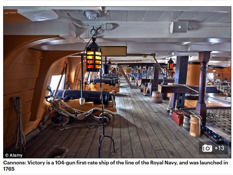
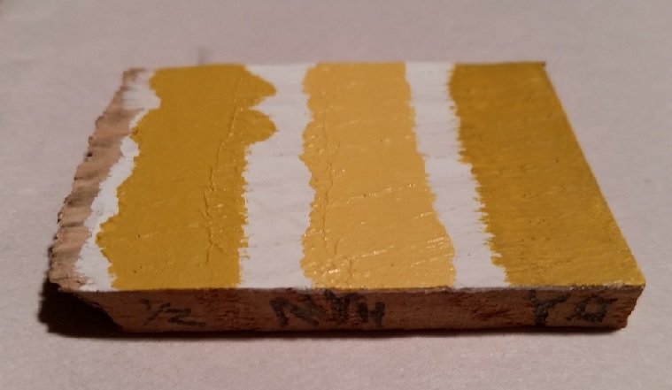
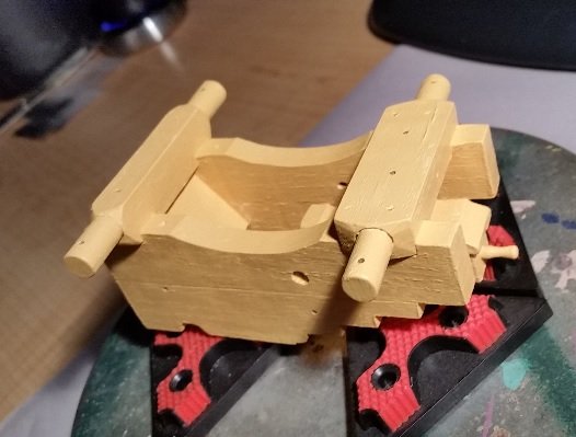
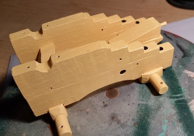
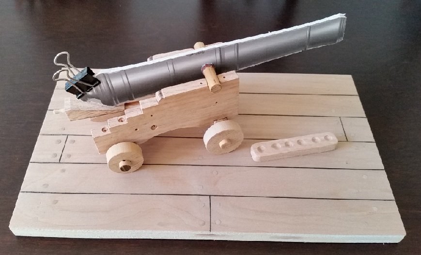
Now was time to yellow wood glue the carriage together, wipe it all down with TACK CLOTH to remove all the dust particles, and finally prime the wood with GESSO SURFACE PREP. This is a white water base coating that dries to the touch quite quickly, but I let it sit over night. Some of the grains popped out a bit (swollen) and a few feathery bit poked out. I like the look of the wood grain but the feathery bits need to be removed. As for the finish coat colour of the carriage, I've seen them painted grey, red, black, brown, and left bare. Mine was to be YELLOW OCHRE in colour as I've read that this was the original colour of the ship's gun carriages for the time (ref: https://www.dailymail.co.uk/news/article-2583165/Nelsons-flagship-HMS-Victory-true-colours-blue-deck-none-hideous-orange.html). The very first photo at the beginning of this build and the following image are the proof. Unfortunately I found Yellow Ochre to be too brown for me, and so after some testing I went with Naples Yellow Hue which is slightly less brown and more yellow. I used Liquidtex Professional Heavy Body Acrylic series 2 paint. All fittings will be black and the TRUCKS (wheels) will be left bare.
- 125 replies
-
- 9
-
-
- 9 pound naval cannon
- 3d cannon barrel
- (and 1 more)
-
To get a better idea of the size and be able to better determine the display case dimensions I made a mock up of the cannon, mounted it to the carriage and placed everything on the base. I originally thought the case would be 5-1/2" tall (measured from the open bottom lip to the inside top of the case) but this mock up had me drop the 1/2". I did some pricing. To purchase an adequate supply of 3mm (1/8") thick clear acrylic sheet (Plexiglas), some Plastic solvent glue (Weld-on #4SC), an applicator (20cc syringe with 16 gauge blunt needle), and acrylic cutting tool would cost upwards of $251 CDN plus taxes and shipping. I asked for a quote from people who do this for a living and all said and done it was $200.56 CDN including taxes and my picking it up. This is the first cover I will have ever had and I fear it will be prettier than my model. I ordered my Plexiglas from a local company named Plastruct Polyzone in Vineland, Ontario. They have my base to fit the case to and called to let me know my case was a total of 1/32" out of square from short end to short end (at 1/64" skew per end). The long sides were parallel. This company did work for the firm I was last employed with, and those items were to four and five decimal place tolerances, so I know they are that good... but my table saw is not. They notified me the case would be ready for pickup on the 14th of November (shy one day of two weeks away as today is 1 Nov). Just received another e-mail the following day (Friday the 2nd of Nov) that the case is ready for pickup. I cannot get there until Monday.
- 125 replies
-
- 7
-
-
- 9 pound naval cannon
- 3d cannon barrel
- (and 1 more)
-
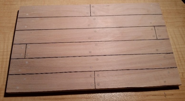
I drilled out the holes and cut my treenails from 1/8" diameter dowelling at 1/2" long. I pushed them into the holes with a dab of yellow wood glue with a small amount projecting above the board. I cut them flush with my Veritus Flush Cut Saw, wiped the board with a damp cloth and later sanded it all and wiped it once again. After all of this I needed to run my V chisel through the notch and re-darken the caulk lines with the my pencil.
- 125 replies
-
- 7
-
-
- 9 pound naval cannon
- 3d cannon barrel
- (and 1 more)
-
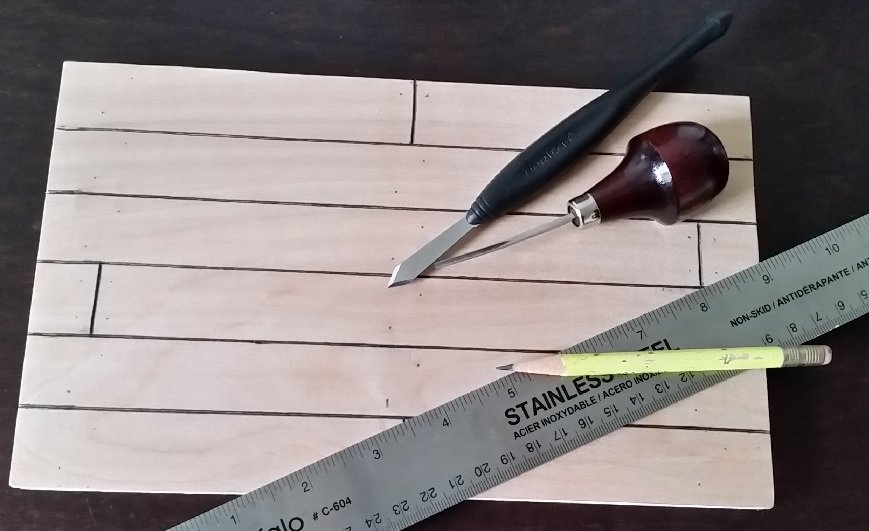
I practised with a scrap piece of plywood to assure I had the treenail dowel drilled hole size and the scribed caulking line cut technique correct. I scribed the line with my Veritus Scriber drawn against a cork backed straight edge held down firmly with one hand. I then went over the lines with a mini Vee notch chisel to widen the line. The line was darkened with a sharp HB pencil. The pencil required continuous sharpening to assure it reached the bottom of the notch.
- 125 replies
-
- 7
-
-
- 9 pound naval cannon
- 3d cannon barrel
- (and 1 more)
-
Prior to starting the other metal pieces I decided to cut and lightly mark (with a soft HB pencil) the deck plank and treenail layout.
- 125 replies
-
- 6
-
-
- 9 pound naval cannon
- 3d cannon barrel
- (and 1 more)
-
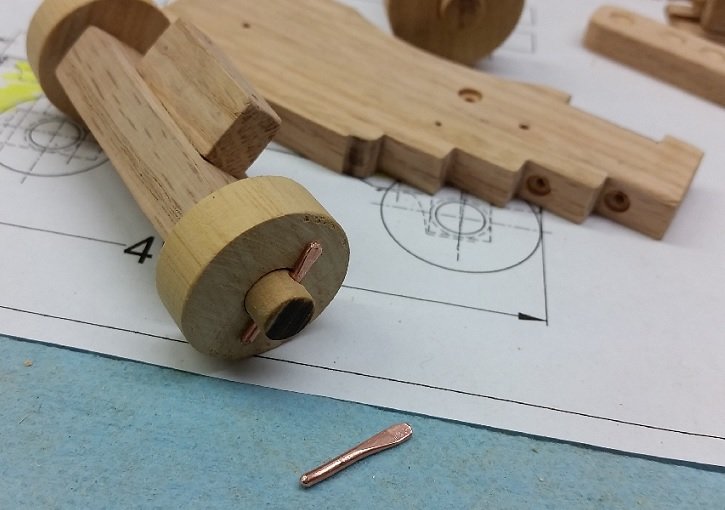
LINCH PINS were made from copper wire. One end flattened in the vise then filed to shape. Measured and cut to length and the lead "pin" end was filed round. The wire was straightened as best as I could and test fitted. Three of the four wheels needed to be sanded thinner so the pins could be driven into place.
- 125 replies
-
- 5
-
-
- 9 pound naval cannon
- 3d cannon barrel
- (and 1 more)
-
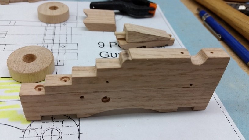
I went back to the BRACKETS (CHEEKS) and slightly countersunk three holes in each using a small brad bit. Then I drilled in the missing bolt holes on the top for the trunnion Cap Square and the bottom for the Fore Axletree support bracket. This was followed with some light sanding
- 125 replies
-
- 5
-
-
- 9 pound naval cannon
- 3d cannon barrel
- (and 1 more)
-
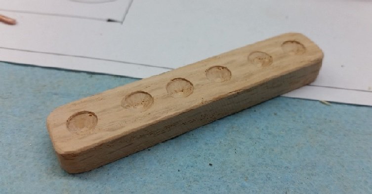
I have a sheet of 1/2" maple finished plywood that I can make the mounting base from. The planks can be scored in and the joints darkened with a lead pencil. The treenails holes can be drilled and filled with 5/32" diameter dowelling. The mounting base will be placed on a sub plate that will create a ledge for the Plexiglas case to rest on. The Plexiglas will be pinned to the mounting base so it doesn't separate from the base if picked up by the glass. The outside of the sub plate may be completed with finish moulding. My next part to work on was the CANNON BALL RACK. This was cut out on the scroll saw, sanded and the divots were marked off and drilled in. I am considering leaving this single piece unpainted as this is how they seemed to be when mounted on deck.
- 125 replies
-
- 5
-
-
- 9 pound naval cannon
- 3d cannon barrel
- (and 1 more)
-
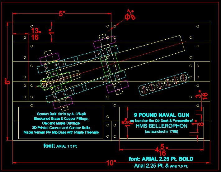
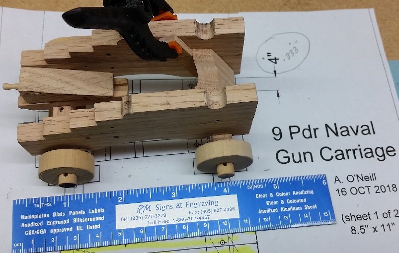
Prior to this, I decided to put my thoughts down on paper for the display case. The topic of our October Model Shipwrights of Niagara club meeting happened to be on building display cases. If you are interested in downloading a very informative PDF of this presentation go to the blog page of our website ( https://modelshipwrightsofniagara.weebly.com/ ) and search for October 2018. I copied the top view of my carriage and added a crude tracing of the cannon to get the overall size so I could pick a display mounting base size. To this I added the cannon ball rack to get the full effect. 6" x 10" seemed perfect. The inside of the Plexiglas case would fit over this. I decided the model would be displayed as if it were on a ship's deck. I drew the planks at 12" width, added a few staggered butt joints and the treenails. Then I created the information plates and decided their placement. I have yet to decide if they will be engraved brass or white on black lamacoid labels with bevelled edges... or something else. I've also played with the text quite a few times and am still not quite happy. Less is usually more but sometimes not enough. 9 Pdr Naval Carriage Display Board Size Dwg - AON - 28OCT2018.pdf
- 125 replies
-
- 3
-
-
- 9 pound naval cannon
- 3d cannon barrel
- (and 1 more)
-
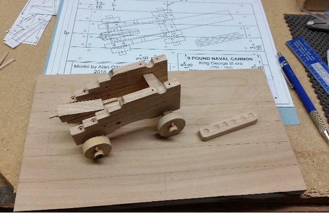
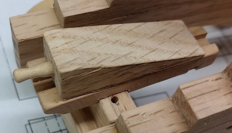
Here is the final dry fitted assembly. The Transom is held in place and kept from falling with a small temporary shelf board clamped to one Bracket. It requires a few more holes to be drilled in the brackets before I start on the hardware.
- 125 replies
-
- 10
-
-
- 9 pound naval cannon
- 3d cannon barrel
- (and 1 more)
-
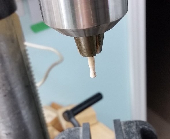
The QUOIN HANDLE was made of maple dowelling, filed and sanded to shape while mounted in the drill press chuck. A pocket was drilled in the Quoin with the nearest sized number drill I had and the Handle was filed once again to fit quite snuggly in the hole and so is one of the few pieces not glued.
- 125 replies
-
- 9
-
-
- 9 pound naval cannon
- 3d cannon barrel
- (and 1 more)