AON
-
Posts
2,871 -
Joined
-
Last visited
Content Type
Profiles
Forums
Gallery
Events
Everything posted by AON
-
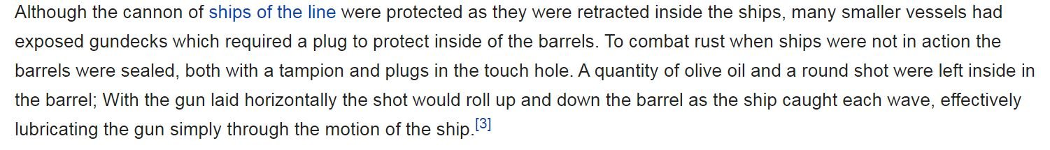
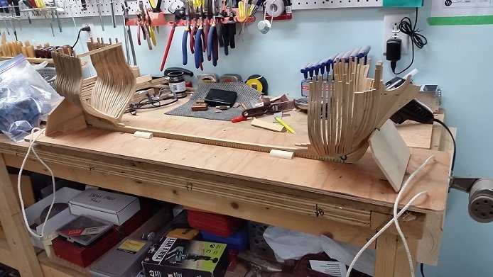
 All forward cant frames are installed. I have P-forward and P-aft (both square frames) to install before I move to the next stage. P-fwd is cut and glued. P-aft is cut and the foot is assembled tested, adjusted and finally dry fit. Now I can complete gluing it together. Hope to be installing frame spacer chocks by Thursday so I can bring it back to our club meeting this Sunday.
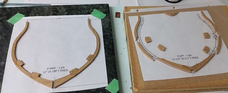

-
Should have also mentioned I purchased #6-32 threaded rod, hex nuts and flat washers a Lowes in Niagara Falls on Tuesday. This will be to mount the model to the build board through the keel, but I will do this after sanding the cant frames which at my pace may be next year. Right Derek? Have to repair my uncles coffee table first.
-
Now I just discovered STEP files are better than IGES files because they are newer, IGES is 20 years old and can convert with gaps or missing info. still trying them both out. Inventor LT (at $520 Canadian a year) is closer to what I am use to using and all my files are on my computer. Fusion 360 for hobbyist is free, very similar, but cloud based... your stuff goes off site like all those celebrity photos that never should have seen the light of day. I've read you can save to your hard drive and work on it. I'll have to give this a try. I am not a fan of having no choice but to have my files being "out there". Is that privilege worth $520 a year?
-
Thanks for the reply. I just discovered it only works with a paid supscription. If you use the free hobbyist version the ipt files needs to be converted to an igs, stp or similar type file. I tried this moments ago and it worked.
-
I just downloaded the free hobbyist version of Fusion 360. I've been able to create new parts and save the files without issue. The problem arises when I attempt to OPEN an Inventor 2011 or Inventor 2015 part file. They (two different versions) upload fine. I can see them in the project folder I created. When I pick them and the menu opens there is no OPEN option displayed as when I opened the new parts I created and saved to the same project folder. Does anyone have experience with this program; uploading/opening Inventor part files? I also understand the program is supposed to convert the file to a Fusion 360 part extension but that didn't happen. Does it happen after successfully opened in the program and then saved? Or is it that it is the free hobbyist version and that function is not available in that free download?? Thanks for any help offered.
-
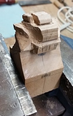
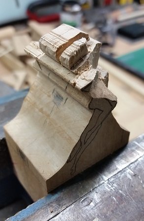
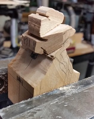
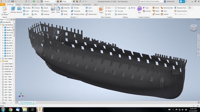
So much happening. It took a while, but after having looked at it from every angle, and realizing all my guide marks would eventually be chipped away... then getting some words of encouragement, I started removing material from the block of Costello that with some prayers will hopefully become my ship's figurehead. I was told to imagine a cloth draped over the finished part... now remove everything up to the cloth. Then with the help of the maquette to visualize the finished part, remove everything else. I have also had to deal with my 3D program loss. It was from my last employer for working at home (you are allowed to copies), but since I am retired now I cannot re-register the copy I had. So I am test driving Inventor LT 2020 - paid annual subscription required (which does not allow assemblies as the full version does but you can import other parts as blocks into a part to essentially create an assembly.. see screen capture below... I rebuilt my hull assembly in about 20 minutes), and Fusion 360 for hobbyists - free version (an Autodesk program which is very similar to Inventor ... same people make it). It is suppose to open Inventor parts but so far I have had no success with it. If anyone has experience with Fusion 360 I could use some directions. I will post this elsewhere on the forum. I've also purchased an upgrade to my music sheet creation/playing program but it doesn't work properly either. Why do these guys release these upgrades before they are ready? Oh yeh... they want your money. I am presently assembling my last forward cant frame (P1 at 0.9° offset) and will install P-aft and P-fwd prior to adding the spacer chocks between frames to stiffen it up as Druxey advised. Then I will pin the heels of the 1st futtocks to the deadwood with treenail type pins in lieu of the monofilament bolts as I want the extra strength... again as recommended by Druxey. I've read that if making treenails from round bamboo skewers, they should be cut square (remove the round edges) by way of two cutters clamped between a spacer block in a vise. So that will be one more thing to McGiver.

-
Gun Spile
AON replied to Mark Allen's topic in Discussion for a Ship's Deck Furniture, Guns, boats and other Fittings
I've not a clew. Beats the shot out of me. -
If you look at the plan below that frame (R4) has a large gap on both sides. I was going to deal with it's spacing with the chocks between frames but it is off and back on now. The bolts are in the scarph joint (outboard to inboard) not between station frames (forward/aft). A.
-
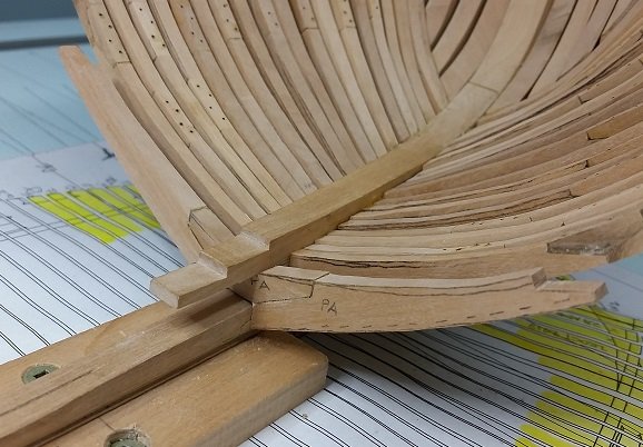
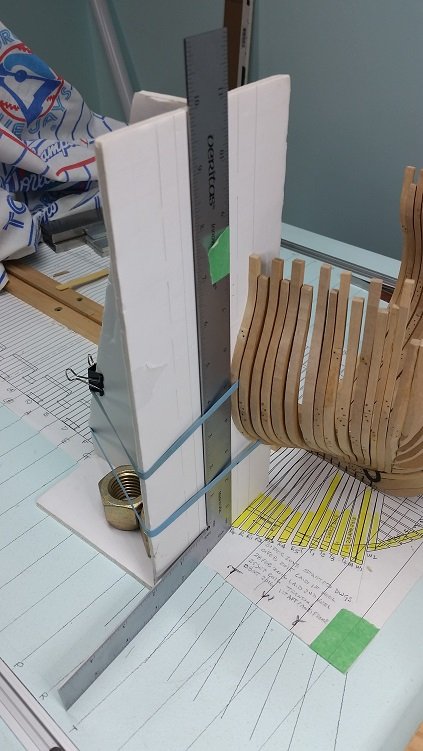
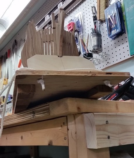
Looking back at the last week I cannot believe how many of the forward cant frames I've removed, adjusted, and reset. It is almost as if I made the whole thing three times. I am happy to say I have everything tiddly now. Last week I had lunch with one of our local club members and discussed a problem I was having and some solutions I had come up with and the new problems they introduced. Of course this was an issue he had dealt with a millennium ago and he described his simple solution for which I have attached the photo below. The problem is that I can use a square to align the outboard edge of a frame with the plan below on the build board and I can use tape to mark the height of the top of the frame, but I just couldn't seem to get the top of the frame to properly align with the plan on the build board. His solution was to simply draw a line on the frame support. Put the line on the inside or outside of the top of the frame on the plan below and position the top of said frame with the same line above. So simple. Sometimes you can't see the forest for the trees. I lightly drew multiple lines equally spaced to give me options. In the photo below the top of my frame aligns on the inboard edge with the line and the plan below. Four and a half frames to go before the spacer chocks go in between them, and then I bolt all the first futtock frames pieces to the keel (wooden bolts for strength in the joint). I had one decision I've been putting off. Some time ago I asked about bolting patterns as each scarph joint is supposed to be three bolts per the contract. Druxey had suggested a triangle pattern, but I had found a sketch in a modelling book with a diagonal pattern. Had it been an historical photo or Admiralty drawing I would have marched forward with it. I admit it seems most logical to me as no bolts are near another that might cause the wood to split. At that time I had decided to only use two bolts diagonally and ponder on it some more. I could easily add the third between those two before fairing.... or I leave it at two and call it a day. I have decided to leave it at two as it is more trouble than it is worth. At full scale there is a lot of room, but at 1:64 it is rather tight.
-
Good evening Derek Yes... I move at a snails pace. One reason is because I have far too many interests and each takes a bite of my time. The last has been yet one more issue with my home computer that has lost me the access to my copy of Inventor (3D modelling) from my last employer. I am test driving Inventor LT which I think will do what I want/need for the next few years. I also removed yet more frames that were not quite right. I (we) are so fortunate to be so close to a couple great talents. I had lunch with one of them the other day and his words of encouragement meant so much. I've said to all that care to listen that this will likely be the only ship I build. Need time to enjoy my retirement... like scratching noise from the strings of my violin. I like coffee, tea, jamiesons. Give me a call and we will work it out. Take care. A.
-
Gun Spile
AON replied to Mark Allen's topic in Discussion for a Ship's Deck Furniture, Guns, boats and other Fittings
I would have said it was a naval carriage installed in a land base operated by the army so they put their barrel and metal wheels on it ... but what the heck do I know... then again the quoin is missing it's handle. I attributed this to Parks Canada. Possibly they Frankensteined the whole thing. Hmmmm???? -
Gun Spile
AON replied to Mark Allen's topic in Discussion for a Ship's Deck Furniture, Guns, boats and other Fittings
Here is a photo I took in October at Ft George in Niagara on the Lake. It does not have the metal on the lower corner of the cheek Possibly it is an era thing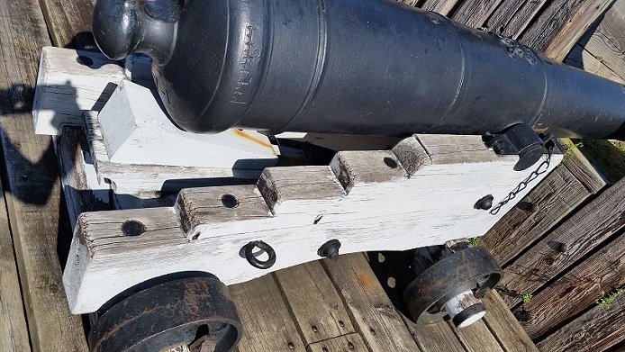
-
Gun Spile
AON replied to Mark Allen's topic in Discussion for a Ship's Deck Furniture, Guns, boats and other Fittings
I imagine it to be a protective wear plate on the bottom or lower rear corner of the cheek. I admit I did not notice these on the naval guns at Fort George in Niagara on the Lake here in Ontario, Canada. If I get my computer back this afternoon I will dig up the pictures I took this summer and have another look. -
Thanks for the reply re: treenail and plank sizing, Ben. I am trying to better appreciate why and when various size treenails are employed. Found a wooden ship building book dated 1919 with guidelines based on tonnage and joint location for treenails and bolts but not sure it hadn't changed from a century or two earlier.
-
I think #18 is 0.018 diameter x 48 (at 1:48 SCALE) = about 7/8" diameter full size. May I ask: What thickness is the plank?
-
Well the trip to the monthly club meeting, this time held at Lee Valley Tools in Niagara Falls, was a complete success. The ship made it there and back without any damage. She is back on the build table now. My presentation on DIGITALLY PHOTOGRAPHING SCALE MODELS was well received, or so I was told. If anyone is interested in downloading a PDF copy just visit our club website (Model Shipwrights of Niagara address below in my signature line) and go to our BLOG page. Scroll down a wee bit and it is there.
-
Gun Spile
AON replied to Mark Allen's topic in Discussion for a Ship's Deck Furniture, Guns, boats and other Fittings
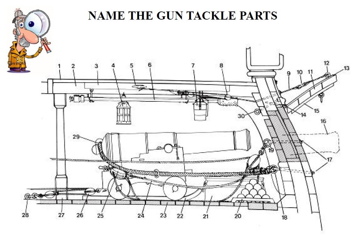
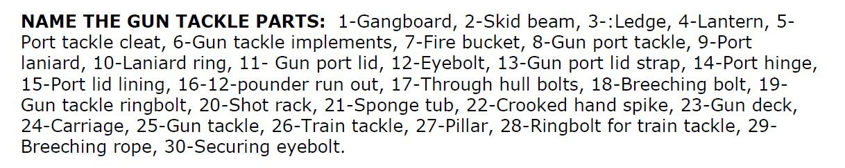
Mark Allen here are some images for reference when assembling your naval guns and tackle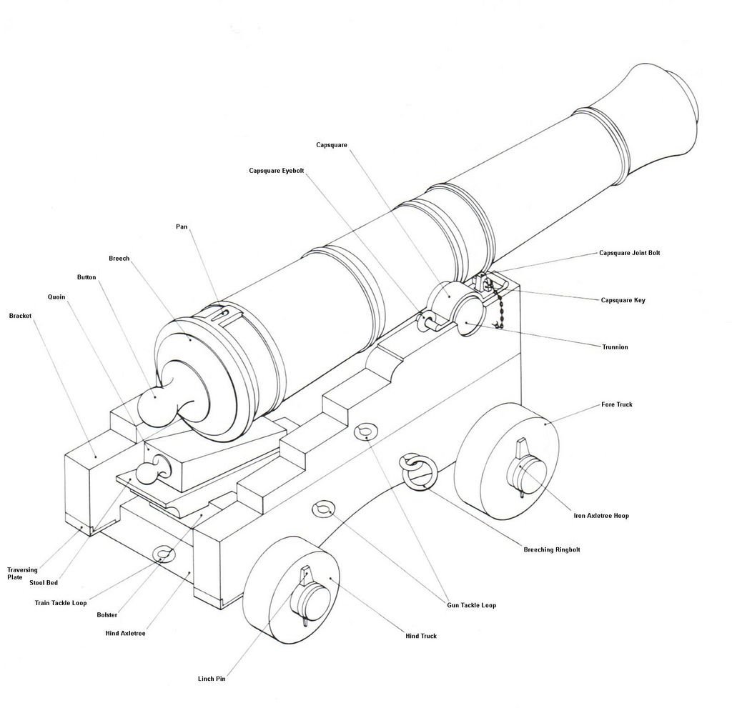
-
Gun Spile
AON replied to Mark Allen's topic in Discussion for a Ship's Deck Furniture, Guns, boats and other Fittings
That wedge with the handle for adjusting the elevation of the canon is called the "quoin". A "spile is technically a cone with the pointed end cut off leaving a stubby plug. -
Need CAD type program
AON replied to Sambini's topic in CAD and 3D Modelling/Drafting Plans with Software
The free version of Draftsight will cease to run after 31 December 2019... they have decided to charge an annual fee. The hobby version will be $99 and does not do 3D. It is strictly 2D If you are able to spend more money there is a version that will do 3D. -
welcome aboard fitz301
-
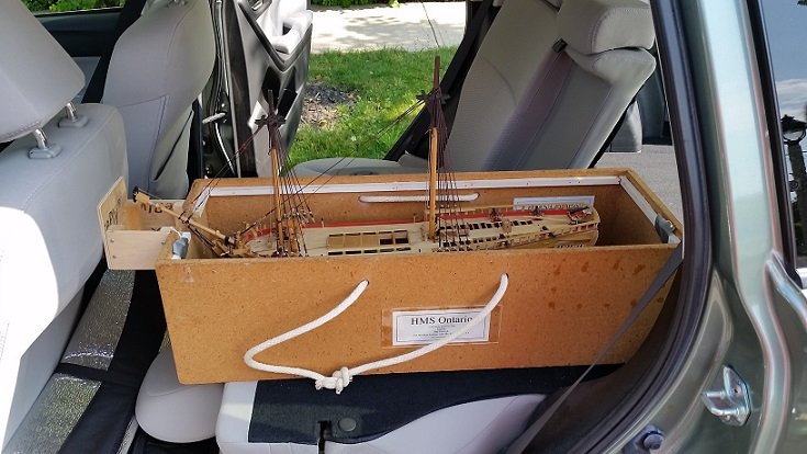
here is a picture of our club members ship model carrying/travel box. He had to add an extension to the front for the bowsprit! The ship is mounted to a pull out board similar to the one I built above.
-
Thought about taking pictures (yet again) but people don't come to the meetings to look at pictures. So today I made a carrying board which goes inside a cardboard box. As time goes on and things get taller I'll make a plywood box. I screwed two runners along the length on the underside for stiffness and added to pull ropes passing through holes in the plywood base with stopper knots (figure eight knot) so I can lift it out of the cardboard box. I did not invent this. One of the more skilled members of our local club made himself one... so I copied him.

-
Yes Druxey, you told me this last year for the aft cant frames and I did not forget. I am reluctant to do this until I have them all done and I am reasonably happy with the locations... as I might need to remove some to adjust before sanding (fairing). As you described, I find the aft frames are quite stiff now.
-
Gun Spile
AON replied to Mark Allen's topic in Discussion for a Ship's Deck Furniture, Guns, boats and other Fittings
found this
-
Gun Spile
AON replied to Mark Allen's topic in Discussion for a Ship's Deck Furniture, Guns, boats and other Fittings
There is nothing mentioned in the Manual of Instruction for 18th century Artillery (including naval pieces).