
HOLIDAY DONATION DRIVE - SUPPORT MSW - DO YOUR PART TO KEEP THIS GREAT FORUM GOING! (89 donations so far out of 49,000 members - C'mon guys!)
×


AON
-
Posts
2,866 -
Joined
-
Last visited
Content Type
Profiles
Forums
Gallery
Events
Everything posted by AON
-
While transcribing posts from old newspaper articles regarding HMS Bellerophon, I came across the following today... Belfast Commercial Chronicle - Monday 6 January 1806 AUTHENTIC ACCOUNT OF THE DEATH OF LORD NELSON. About the middle of the action with the Combined fleets, on the 21st of October, Lord Nelson was upon the quarter deck, where he had resolved to take his station during the whole of the battle. A few minutes before he was wounded, Mr. Bourke was near him; he looked steadfastly at him, and said, "Bourke, I expect every man to be upon his station." Mr. Bourke took the hint, and went to his proper station in the cockpit. At this time his Lordship's Secretary, Mr. Scott, who was not, as has been represented, either receiving directions from him, or standing by him, but was communicating some orders to an officer at a distant part of the quarter-deck, was cut almost in two by a cannon shot. He was expired on the instant, and was thrown overboard. Lord Nelson observed the act of throwing his Secretary overboard, and said, as if doubtful, to a Midshipman who was near him, "was that Scott?" The Midshipman replied, he believed it was.. He exclaimed, "Poor fellow!" He was now walking the quarter-deck, and about three yards from the stern, the space he generally walked before he turned back. His Lordship was in the act of turning on the quarter-deck, with his face towards the enemy, when he was mortally wounded in the left breast by a musket-ball, supposed to have been fired from the mizen-top [sic] of the Redoubtable French ship of the line, which the Victory had attacked early in the battle. He instantly fell. He was not, as has been related, picked up by Captain Hardy. In the hurry of the battle, which was then raging in the greatest violence, even the fall of their beloved Commander did not interrupt the business of the quarter-deck. Two sailors, however, who were near his Lordship, raised him in their arms, and carried him to the cockpit, He was immediately laid upon a bed, and the following is the substance of the conversation which really took place in the cockpit, between his Lordship, Capt. Hardy, Mr. Bourke, and Beatty: Upon seeing him brought down, Mr. Bourke immediately ran to him. "I fear," he said, " your Lordship is wounded."---"Mortally, mortally."---"I hope not, my dear Lord; let Mr. Beatty examine your wounds."---"It is of no use," exclaimed the dying Nelson, "he had better attend to others." Mr. Beatty now approached to examine the wound---his Lordship was raised up; and Beatty, whose attention was anxiously fixed upon the eyes of his patient, as an indication the most certain when the wound is mortal, after a few moments glanced his eye on Bourke, and expressed his opinion in his countenance. Lord Nelson now turned to Bourke, and said, "Tell Hardy to come to me." Bourke left the cockpit. Beatty now said, "suffer me, my Lord, to probe the wound with my finger; I will give you no pain." Lord Nelson permitted him, and, passing his left hand around his waist, he probed it with the fore-finger of his right. The description of the surgeon, however, is so accurate and scientific, that, by his permission, we thankfully give it: "On his Lordship's being brought below, he complained of acute pain in about the sixth or seventh dorsal veterbra [sic], of privation of sense, and motion of the body and inferior extremities; his respiration was short and difficult; his pulse weak, small, and irregular; he frequently declared his back was shot through---that he felt every instant a gush of blood within his breast; and that he had sensations which indicated to him the approach of death. In the course of an hour his pulse became indistinct, and was gradually lost in the arm; his extremities and forehead became some afterwarde [sic] cold: he retained his wonted energy of mind and exercise if his faculties; until the latest mement [sic] of his existence; and when Victory, as signal as decisive, was announced to him, he expressed his pious acknowledgements thereof, and heart-felt satisfaction at the glorious event, in the most emphatic language. He then delivered his last orders with his usual precision, and, in a few minutes after expired without a struggle" COURSE AND SITE OF THE BALL ASCERTAINED SINCE DEATH. "The ball stuck the fore-part of his Lordship's epaulette, and entered the left shoulder immediately before the prosessus acromion scapulae, which it slightly fractured: it then descended obliquely into the thorax, fracturing the second and third ribs; and, after penetrating the left lobe of the lungs, and dividing in its passage a large branch of the pulmonary artery, it entered the left side of the spine, between the sixth and seventh dorsal vertebrae, wounded the medulla spinalis, and, fracturing the right transverse process of the seventh vertebrae, it made its way from the right side of the spine, directing its course through the muscles of the back, and lodged therein, about two inches below the inferior angle of the right scapula.---On removing the ball, a portion of the gold lace and pad of the epaulette, together with a small piece of his Lordship's coat, were found firmly attached to it. "W. BEATTY, SURGEON." When Bourke returned into the cockpit with Captain Hardy, Lord Nelson told the latter to come near him.---"Kiss me, Hardy," he exclaimed.---Captain Hardy kissed his cheek,---"I hope your Lordship," he said, "will still live to enjoy your triumph."---"Never Hardy!" he exclaimed, "I am dying---I am a dead man all over---Beatty will tell you so---bring the fleet to an anchor---you have all done your duty---God bless you."---Captain Hardy now said, "I suppose Collingwood, my dear Lord, is to command the fleet."---"Never," he exclaimed, "whist I live," ---meaning, doubtless, that, so long as his gallant spirit survived, he would never desert his duty. What passed after that was merely casual: his Lordship's last words were to Mr. Beatty, whilst he was expiring in his arms, "I could have wished to have lived to enjoy this; but God's will be done."---"My Lord." exclaimed Hardy, "you die in the midst of triumph"---"Do I, Hardy I" [?" - sic] ---He smiled faintly---"God be praised!" These were his last words before he expired. At the funeral of Lord Nelson of the 9th, the whole of the Morning Service will take place prior to the burial Service. The cable that now extends from the top of the dome, in ST.PAUL'S, is intended to hang all the colours of the different powers, taken by the gallant Lord. At the top will be displayed the English flag of the Victory, which , on a signal being given, will be lowered into the grave, with the remains of the ever to be lamented Noble Tar. The Plate upon Lord NELSON'S coffin is gold.---The dimensions are to be thirteen inches by nine. It is to be the same size as the Duke of GLOUSHESTER'S. His MAJESTY'S goldsmith is preparing it. The following inscription is to be upon it:--- DEPOSITUM. The Most Nobel Lord HORATIO NELSON, Viscount and Baron NELSON of the Nile, and of Burnham Thorpe, in the County of Norfolk. Baron NELSON of the Nile, and of Hillborough, in the said Country. Knight of the Most Honourable Order of the Bath; Vice-Admiral of the White Squadron of the Fleet; and, Commander-in-Chief of his Majesty's Ships and Vessels in the Mediterranean. Also, Duke of BRONTE, in Sicily; Knight Grand Cross of the Sicilian Order of St. Ferdinand, and of Merit. Member of the Ottoman Order of St. Joachim. Born September 29, 1758. After a series of transcendent and heroic Services, this Gallant Admiral fell gloriously, in the moment of a brilliant and de- cisive Victory over the Combined Fleets of France and Spain, off Cape Trafalgar, on the 21st of October 1805.
- 4 replies
-
- 12
-

-
 Canute I am glad you appreciate the old reports. They are definitely written on behalf of the victors. My favourite newspaper post to date is the announcement of the auction of the prize of a ship and the goods on board. It reminds me of the prize my grandfather lost out on in WWI. We had found a record of it. I was surprised they were still doing that then... at such a late date. I believe the practice of selling prizes and distributing the money is not done any more. As a kid I thought this was only done by pirates. I never found history as exciting in school. I suppose it is like a fine wine... gets better with ageing. It is likely why the younger generation repeat the mistakes of the past... they are not old enough to appreciate the lessons offered with the temperment if time. Am I old?
 -
It has been over 24 hours and my wrist and hand are much better but not 100% as yet, possibly one more days rest is called for. However my butt reminds me of the fall every time I take a seat. Thank you Mark and all others for thinking so much of my favourite ship to have downloaded and reviewed my Part 1. The attached PDF is a preview of Part 2. It has a lot more to go so don't expect to see the finished product any time soon. Take care. Alan HMS Bellerophon - Part 2 - Newspaper Articles and Letters - 24 Oct 2019.pdf
-
Had an accident today. My rolling stool ran away as I was going to sit at the scroll saw. Sprained my wrist and my bottom side. Both are quite sore but nothing broken. Difficult to make and pick up my evening tea. Might need to take a few days to recover.
-
And the fellow that introduced me to it.
-
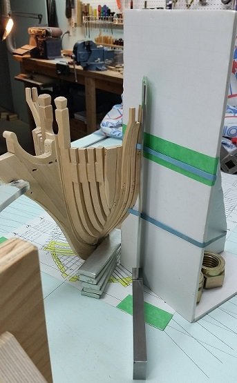
Down in the shop this afternoon for about 3 hours readying three more frames as I struggle with frame T2 on the starboard side. The port side went in quite nicely but it's mate was giving me grief for the last few days. I always need to adjust the taper on the foot to pull the top in or out a wee bit but this one just refused to align. In frustration I put it down on top of the template once more, ready to walk away and then I spotted it. The lowest or first futtock had shifted up and inwards during glue up. It would never align to the adjacent forward frame properly. I took it apart, cleaned it up and now the glued joint is drying once again.
-
Thank you for the favourable comments and likes. As with all works I thought I "had it" but upon yet another review (surely my tenth or more) I discovered some typos and minor corrections. These have been dealt with and the document switched out. So if you see this before you start your review please grab the newer copy above. (and let me know what you think, comments/corrections, etc. by PM if you please)
-
For those interested in the Bellerophon I have been collecting information for years and have compiled the first half (attached PDF) - HMS Bellerophon, Part 1: A Service History for your enjoyment The second half (Part 2) will be transcriptions of newspaper postings and letters from the 1700's and 1800's I have collected 948 newspaper articles, many are duplicate events in different publications. It will be some time to manage these... but then so will my build! HMS Bellerophon - Part 1 - A Service History.pdf
-
Well stated.
-
Thank you Carl. It feels nice to be almost missed... but I always come back. The contract reads the frames were bolted to the deadwood with 1-1/2 inch (3.8 cm) diameter bolts. This would be 0.023 inch (0.58 mm or less than 1/32") at 1:64 scale. I need to draw down to the hole size identified as number 23. These seem quite small and as I am looking for additional strength in the glued joint to the keel I may make them a wee bit larger diameter, especially since there is no #23 on the draw plate. There are Nos. 24, 25, 26, 28, 29, 31, 32, 33, 35, 36, 37, 38, 39, 40, 41, 42, 43, 45, 47, etc. I might try .047 (1.193 mm or 3/64") or 3" dia. to scale. Still thinking about it. Alan
-
ah it works also seems you shouldn't copy and paste
-
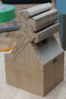
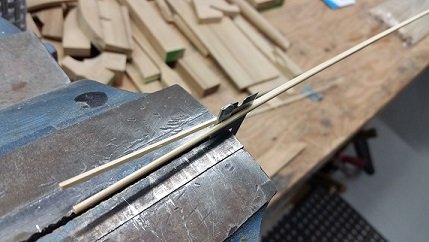
Here we are with summer a happy memory and fall deep in my bones (damp and getting colder). A good summer for fishing, relaxing, and just basically enjoying the outdoors and the sun. Now I find myself back down in the playroom for a few hours in the early afternoon with all my toys. Starting remaking and attaching my forward cant frames earlier this week, so I'll be crawling along on this for a couple weeks. Also stumbled upon some nice bamboo skewers to use as treenails as the others I started making from old bamboo stakes are not so good I also cut out two blank castello blocks for my figurehead carving. I've yet to transpose the sketch widths to the front and rear but I will have enough to keep me from getting bored


-
good morning Druxey I picked your link, copy and pasted each search and hit enter and got nothing. There must be an extra step. help? Alan

-
"The only necessary thing for evil to trumph is for good men to do nothing".
- 366 replies
-
- 3
-
-
- bellerophon
- victory models
- (and 2 more)
-
When I stood by the handrail barrier surrounding that building at ground zero and my host described how people jumped into the canal (that runs along one side) for relief from the scorching heat to only find the water was boiling... I had tears in my eyes... and do so now once again just thinking about it.
- 366 replies
-
- 2
-
-
- bellerophon
- victory models
- (and 2 more)
-
Facinating discussion. The NCO would possibly not have so ornate a head covering. They also would not want it to be too comfortable so as to keep it unoccupied/available. 😆
-
75 years ago today: D-Day -1 My father manned a Bren gun aboard HMCS Caraquet, the flag ship of the 31st flotilla, Canadian minesweepers. They sailed at about 1700 GMT and throughout the night cleared the channel and then in the early morning of the 6th they went to work clearing OMAHA beach for the Americans. Attached is the story, including mention of the moon coming out to temporarily illuminate them to the enemy while they continued to clear the shore. And how they worked through the sun rising until the enemy saw the approach of the massive assembly of ships... and then spotted them. Exactly how my father described it to me except they don't use his words to describe how scared they were the whole time. The 31st Canadian Flottilla - poem.pdf The 31st Canadian Minesweeper Flottilla on D-Day.pdf
-
Oskar24 If I may add, there is the detailed and then the simplified method of doing Plank on Frame. The simplified method does not have scarph joints or chocks in the frames. It might be simple butt joints or even no special joint at all. As the builder you get to decide what you are comfortable doing or want to attempt to do.
-
Potato? ... one persons taper may be another persons angle, but a taper is definitely at a specific angle. (or is it a chamfer?) either way I am buggered
-
Two steps forward.... three steps back. It is the worst dance step ever but leads to one more lesson learnt that will likely never be forgotten. The chocks on the forward cant frames should taper opposite to those on the aft cant frames. It was clearly there in black and white. One lesson learnt some time ago: the second time is always quicker!
-
Thank you Druxey. I will see what I have and hope to give it a try today.
-
Thank you Dowmer. Possibly another trip to the dollar store is in order. 😉
-
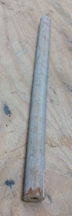
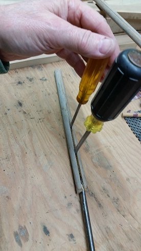
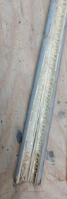
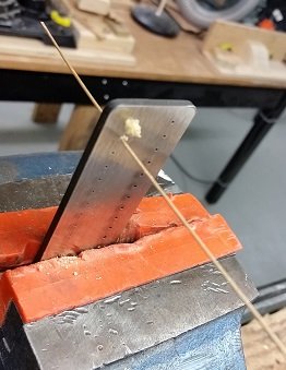
Making treenails (or trunnels). I've searched online, through my small collection of books, and in this forum to find instructions. Allow me to add my take on making treenails with a draw plate. If I have done anything incorrectly I trust one of the more 'weathered' people on this forum might set me on course. First I borrowed (long term no return basis) about a 10 inches (25 cm) in length of bamboo from the garden. This stuff has spent the winter in the garage and is well dried out. It needed to be split and as I am trying to be less of a hazard to myself I did not attempt to do this with a knife. I used three slotted or flat blade screw drives as wedges and split it as I use to split large logs for the fireplace (but without the sledge hammer). Once opened up I could easily identify the soft inner core and the hard outer shell. I needed strips of the white stuff from between these zones. I put the bamboo against a dog (stop) on the bench and pushed a chisel blade through to make smaller strips. Eventually I had to forego the dog as the strips were getting quite thin. The contract reads the frames were bolted to the deadwood with 1-1/2 inch (3.8 cm) diameter bolts. This would be 0.023 inch (0.58 mm) at 1:64 scale. I clamped my draw plate in my vise using soft jaw inserts to protect the draw plate. Looking at the draw plate I can see numbers from 16 to 59 stamped next to the holes. 16 means 0.016 inch (0.4 mm) diameter and 59 means 0.059 inch (1.5 mm) diameter. I need to draw down to the hole size identified as number 23. The holes in the plate are sharp edged on one side and funnel (tapered inwards) shaped on the other side. The tapered or funnel side faces you. The strip of bamboo is fed into the sharp edged side. Once poking through you grab it and pull! I sanded a taper on one end and poked it through the smallest hole it would fit through. I had read that you pull through the draw plate and can assist by pushing lightly from the other side. Let me say this method works for the larger diameter but as it gets smaller you do not want to try to assist by pushing from the far side as the sliver of wood will buckle, or split and buckle. Also, eventually my fingers could not adequately grip the small strip of wood and I needed to employ small hobby pliers to pull it through the draw plate. This did crush and flatten the end of the wood which I nipped off with my chisel and re-sanded a taper to allow me to feed the piece into the plate. I also found that if you push the lead end of the wood through the funnel side a very short distance, it helps to crush and shape the sliver of wood to assist feeding it into the other side. Presently I have a number of slivers of bamboo at hole size number 33 or 0.033 inch (0.8 mm) diameter. This is about 2-1/8 inch (54 mm) diameter at scale. My first piece at 0.023 inch is extremely tiny and I am not certain how this will add any strength to my joint for sanding my frames. I believe I will stick with the larger size as no one but Druxey will be taking a caliper to my build.
-
I believe the block and sheave are both angled at about 7° or so. Yes they sometimes wrote diameter but meant circumference. Steel's tables for rigging are located here: https://maritime.org/doc/steel/tables/pages/032-ShipOf74Guns.htm Thanks to this forum I discovered the site on JSloane's HMS Bellona build. Yes the Canadian younger generation are more metric but it is still mixed for some industry. I am so close to the states that I hear and see many words pronounced and spelt oddly for the way I was taught in grade school. The good thing is no one will take a caliper to your model so close enough is damn good in most cases.
- 366 replies
-
- 4
-
-
- bellerophon
- victory models
- (and 2 more)
