


AON
-
Posts
2,587 -
Joined
-
Last visited
Content Type
Profiles
Forums
Gallery
Events
Posts posted by AON
-
-
The Refit of the Schooner “CHARLIE”
16 June 2014
I have taken on a diversion project which is to complete a build started by a co-worker’s step father whose health has deteriorated to a point he cannot manage it. My working associate does not want anything too fancy.
At present the build consists of
- the hull cut from a solid piece of wood
- the deck cut from a single piece and nailed to the hull
- the cabin walls made from four mitred pieces nailed together
The general shape of the hull somewhat resembles the BLUENOSE but this weekend was one where the gentleman could recall some memory of the vessel and he stated it was not any particular boat.
Link to photos:
http://modelshipworld.com/index.php?/topic/7009-help-please-identifying-sailing-vessel/
My intention is to complete the shaping of the hull, add a rudder, put a roof on the cabin, add a metal hand rail around the deck edge, add masts/yards/gaff/boom and some rigging. Then mount it on a simple base and cradle assembly.
My first task will be to establish the centreline on the underside of the hull and copy the profile, transfer it to stiff cardboard, prove it to the hull and then create a “skeg” template for the piece to be made and added to the underside.
As for the vessels name: CHARLIE is how the gentleman refers to everyone whose name he doesn’t know or may have forgotten. CHARLIE just seems fitting (considering the gentleman's condition) and I have to refer to it as something besides “that boat of yours”.
Meanwhile I have to finish the build of my modelling table (got my saws back from my son yesterday) and I continue to plot out my keel, stem and stern post for my build of my HMS Bellerophon.... mow the lawn, wash the car.... and fit some fishing time in there somehow. I just might have to give up my day job to make time for all this.

-
Druxey: "grasshopper"
that put a smile on my face!
thoughts of dear old David Carradine
(I still think Bruce Lee would have been the better kung fu master)
Chief: Re: time spent on my actual build
This build is still in the planning/layout/research stage and takes 100% of the time I put on it for now
I cannot comment on anything other than the whaler I did 14/15 years ago where I was intimately familiar with them back then so research was minimal and I practically jumped right in after receiving the print from NMM and the photos from my CPO at HMCS Quadra that summer.
Alan
-
Good morning Druxey
Thank you for following.
I see you are everywhere on the forum and cannot imagine the time it must take
I greatly appreciate your and other modellers visits as it somehow puts me at ease.
Recording the measurements and plotting the points is a bit tedious but I will admit joining the dots is fun (is that weird?) I attribute it to the fact that I can see myself getting closer to starting the actual model. There have been some frustrating moments... one major one being trying to read and then make sense of Ree's or Steel's.
I am approaching it as I've done many a new challenging task at work, divide and conquer.
I break it up into much smaller but manageable frustrations and overcome them one by one!
I will also admit I had not factored in the demands of the new season taking me away from all this.... I hear the grass calling me again

but (as I am certain you can attest to) it is much more enjoyable being out in the sun then basking in the ice and snow!

Take care Obi-Wan!
(did I just reveal my age?)
Alan
-
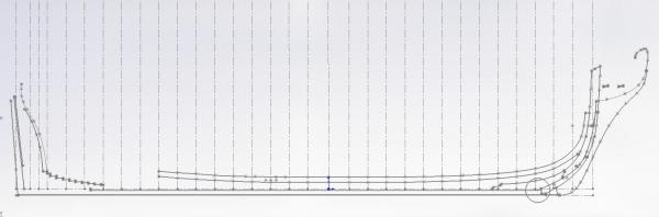
Some minor KEEL, Stem and Stern Post layout progress taking place as I take a break from building my modelling table.
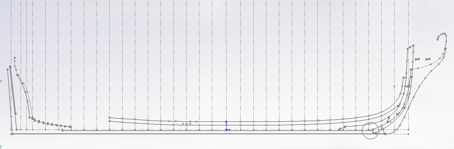
I had taken a multitude of measurements off the plan and am now plotting them to draw the lines to establish the various pieces and the rabbet line.
The circle near the bow is to remind me of something that does not blend well in that area... I need to double check my dimensions and/or redraw the polyline to more reference points.
I am also having some problems at the bow drawing in the edge in the area above the gammoning holes as the plan does not distinguish any detail of this surface edge.
Looking at Ree's Plate X, figure 1, ( I understand they are very similar to Steel's) there are two dotted (hidden) lines that I believe the lower one is what I need.
This area does not look anything like the Vanguard or Bellerophon kits I see being assembled on the forum.
- block for the figure head is not stepped
- two round bobstay holes versus three
- another round hole up above the inboard gammoning hole
Alan
-
Ahhhhhhh
British Columbia aka God's Country .... unless you are speaking to people from Alberta
-
Pete
Nice workshop... and room left over to park your car!
(When needed mine flows out of my designated play area in the dungeon to the rest of the basement)
Some how I would not have thought snows shoes and San Diego, California would go together

-
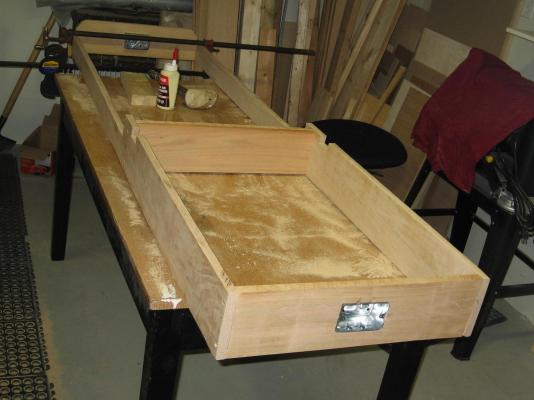
I managed to get quite a bit done this weekend as the following photos will show.
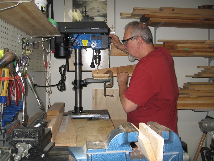
01 drilling holes in legs - using the sticky back templates provided with the mechanism made this step considerably easier
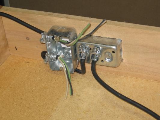
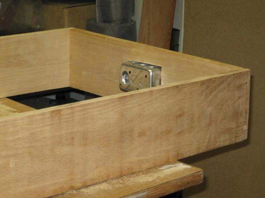
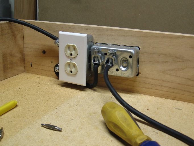
02 wiring - ran wiring to each of the three electrical boxes
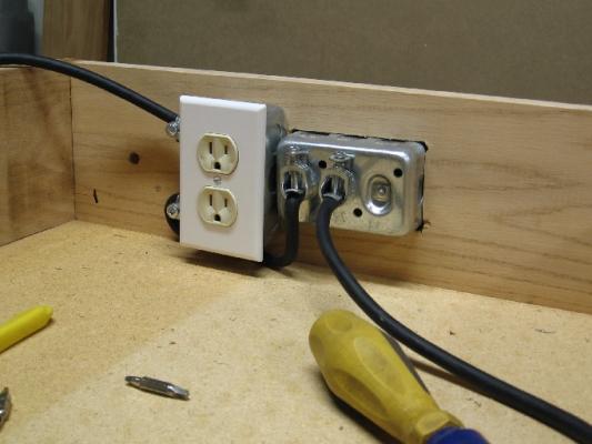
03 wiring - installed the plugs and plates; had to run out to Home Hardware to get a 3 prong plug for the end of the feed wire as the one I thought I had seems to have walked away.
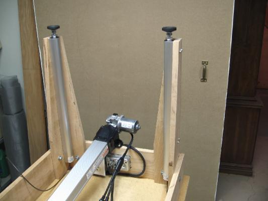
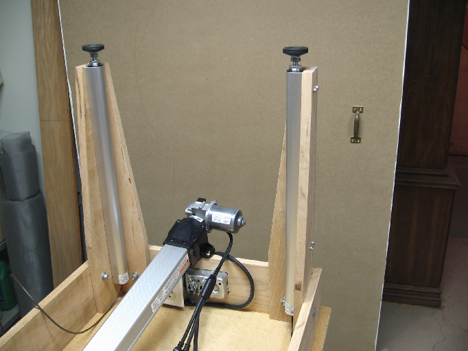
04 mounting legs - everything lined up perfectly; I used socket head cap screws and a flat washer to give me some additional bearing surface area against the wooden leg so when torquing the screws they would crush into the wood a little less
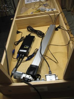
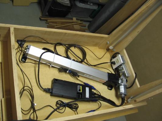
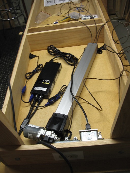
05 laying out mechanism - It was a bit tight as I hadn't allowed for the electrical outlet boxes in my plan; had to skew things to fit
06 securing mechanism - they had provided tie down straps for the tubing (these screwed to the table but no screws were provided); wiring cable sticky back holing slips were provided but I was uncomfortable applying these to the wafer board as I wasn't confident they would hold so I used the extra cable straps. They had provided two screws for the control buttons but I could only use one on each as the other hole was under my frame.
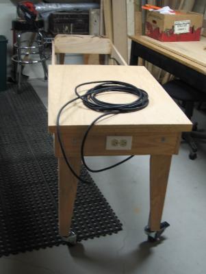
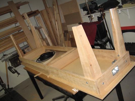
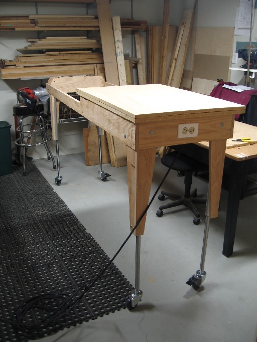
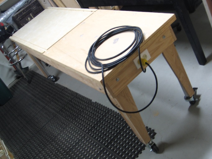
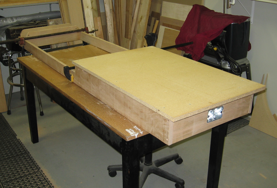
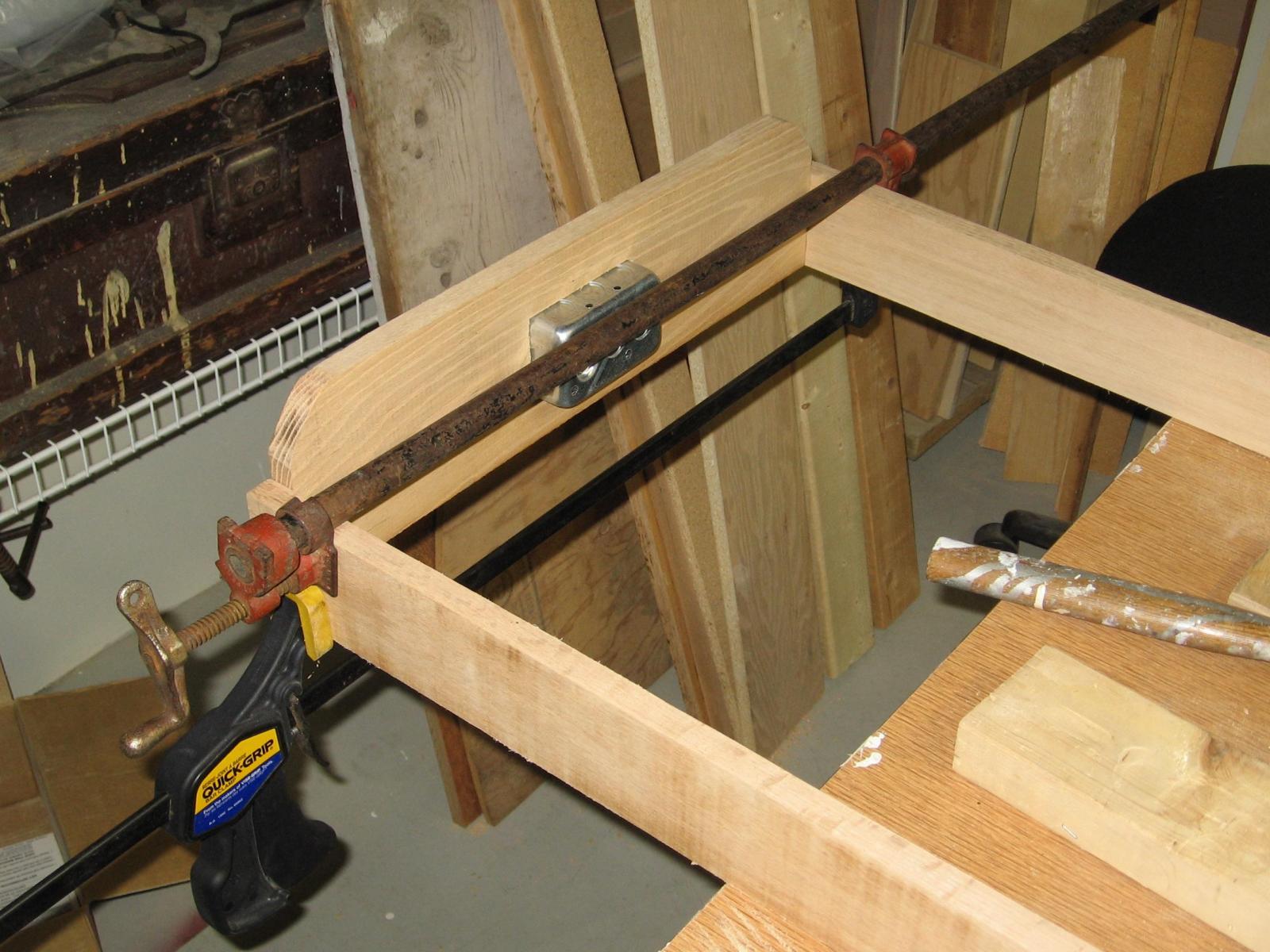
07 table down - this is as far as I was able to go with the assembly
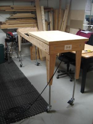
08 table up - raises 15-3/8 inches (390.5 mm) from 30-1/8" to 45-1/2" (767 mm to 1156 mm) in 24 seconds. The lowering was uneven as the far side did not have adequate weight on the cylinders. I placed the model table tops on the table and added a bit more weight and tested again and it all worked fine. When I complete the table assembly it should have enough weight to it.
09 table - a shot of the table with the modelling half placed on top
I will not be able to make the frame for the modelling half for another week as my son has borrowed the cut-off and circular saws for the re-modelling of his home. This will allow me to concentrate on my ship modelling - establishing the rabbet line. I have taken a quad-zillion measurements off the plans and have been plotting them out in my 3D model.
Hope to be posting there again soon.
Alan


-
It was a pre-release notice and won't be out for a month yet
I am locked in on the $CDN price (always more in Canada versus the states) and if it drops (as if that ever happens) I get the lower price.
I am very interested in reading her story and having not seen the first printing I hope it will be one of those few books I cannot put down
-
Thank you Pat.
It is a wonderful feeling to see a mere thought and then vision develop and transform into reality.
Now that it is beginning to resemble an actual table I cannot wait to see it finished... this is when I have to reel myself in a bit to avoid doing something really dumb
For instance, I don't know what I was thinking when I was going to drill the lift cylinder mounting holes with my hand held drill and the legs bolted in place.
It would never have aligned properly!
I took the legs off last night to use my drill press... this will keep them parallel with the surface.
I also double checked the new metric bolts .... they are the correct ones!
Oops! Should have answered your question... eh?
I am thinking one shelf across the bottom with store bought clear plastic (see through) containers/drawer units on it.
I use these for my carving tools at the moment and they seem to work for me
-
Some photos from last night
Just wish I had managed to mount the lift cylinders
I did get out this morning and picked up some real M5 x 25mm bolts and washers at Fastenal
- sonicmcdude and BANYAN
-
 2
2
-
I managed to assemble the fourth leg last night
Drilled and carriage bolted them to the frame
Took out my M5 x 25mm bolts to fasten the cylinders to the legs
Found the correct drill for the M5 bolt by drilling a hole in a scrap piece of wood and fitting the bolt through.
(the markings on my drills are worn off and my vernier calliper is at the office)
Something looked wrong. Put the bolt up against the leg and it was a 1/2" longer than the leg thickness.
The blind tapped hole in the cylinder is just over 1/4" deep
Measured the bolt and it is 1-1/4" long
Took the bolt over to the cylinder and tried to screw it into the hole.... no go.
The bolt isn't an M5 thread!
That put a damper on progress
(note to self: never ever believe the marking on the box)
-
I managed to assemble two more legs last night
One to go, then I'll mount the lift and provide more pihotos
-
The problem with summer time is that there is so many more things to be done... plus it was another gorgeous weekend outside
Once again a small amount of progress
Mounted one additional electrical box inside the frame for the lift motor plug
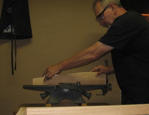
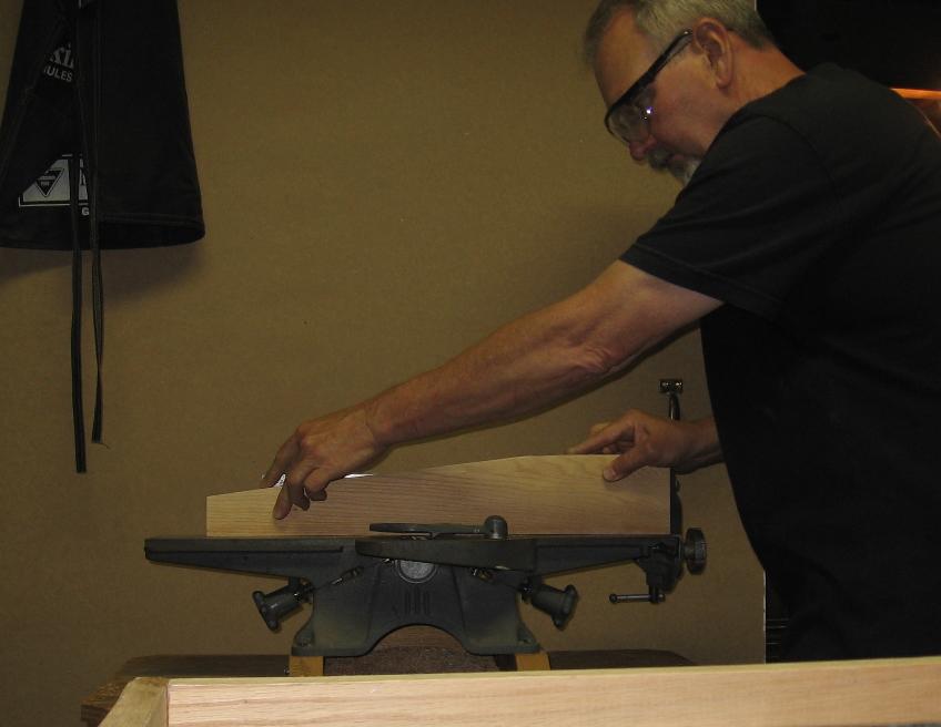
Ran all the legs through my 4 inch Beaver jointer-planer for better fitting
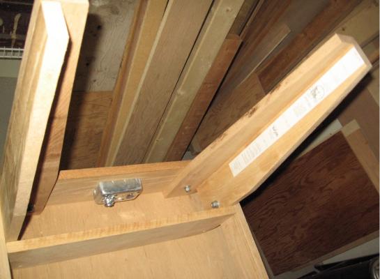
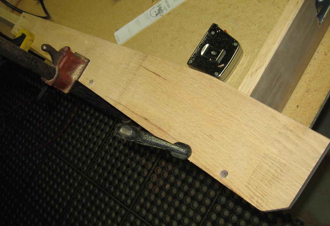
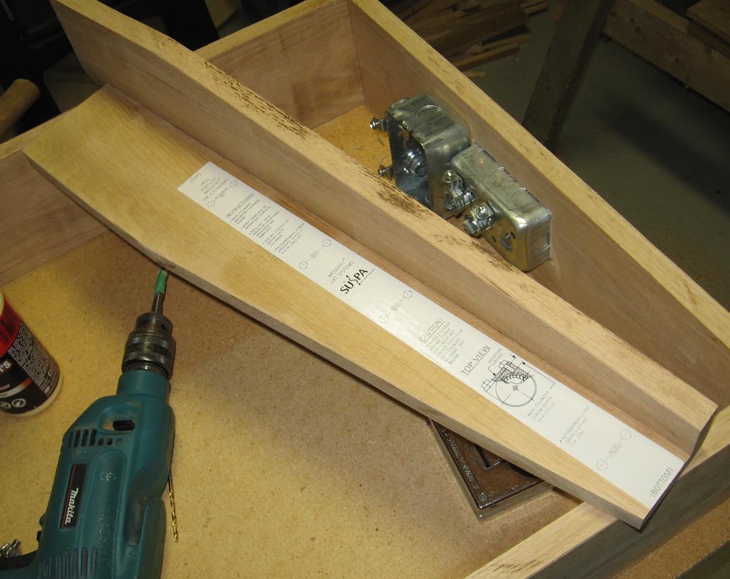
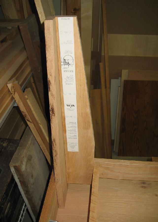
Laid out where the lift mechanism bolt holes would be and then laid out my dowel pins locations
Drilled for three dowel pins, glued up and assembled
Placed the stick on drill template for the lift mechanism to the inside of the leg
Fitted the leg in position
Yet to be drilled and bolted in place
I will make the other three and drill them all for the lift mechanism and mounting to the table frame at the same time
Until later
Alan


-
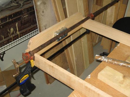
Once again a picture is worth one thousand words!
-
You'll need one extra hand, three more temporary supports and a couple extra tall shots of Canadian Club Classic to get this done!
All joking aside, it must feel great when something so difficult finally comes together!
-
-
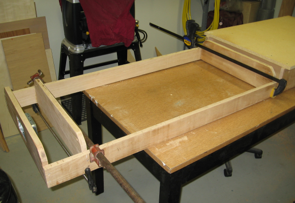
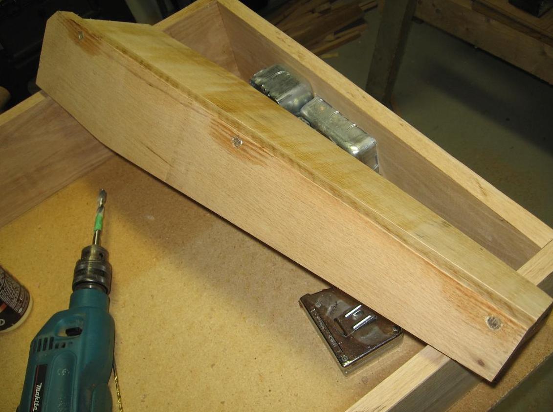
Once again my estimated time to complete the work outdoors was double what I thought it would be
Got about 1-1/2 hours on the table and then had to quite as I was getting tired and that's when dumb mistakes are made
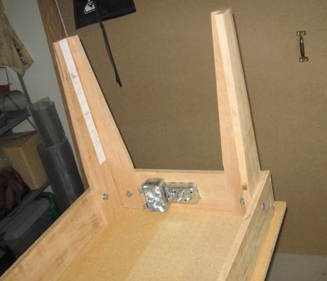
Installed the stationary pin plates onto the table frame
Installed the stationary reference sub-table top
Placed the sub-base tilting table top under the frame and marked off centre
Placed the pivot pin plates near their final location just for show
Yet to do:
Need to make the frame for the underside of the pivot table section and attach to the pivot sub-table top
Attach the pivot plates to the pivot sub-table top frame
Make the pin guide blocks and pins
but before all that I want to first assemble the legs and mount the lift mechanism
Here are a few photos of last nights progress
Alan


-
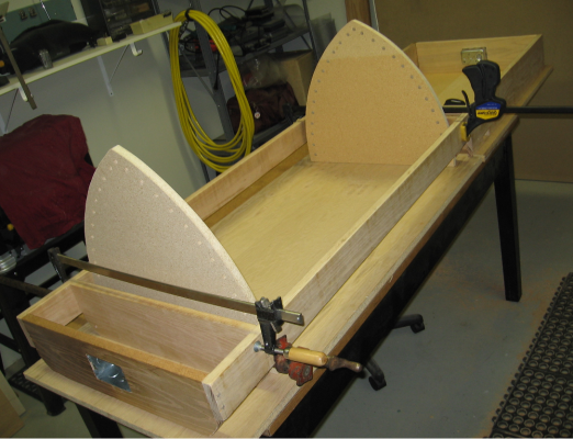
Spent the last two days outside in the garden and will spend at least half of today finishing up out there.
What a beautiful weekend this turned into
I am glad I booked today off work.
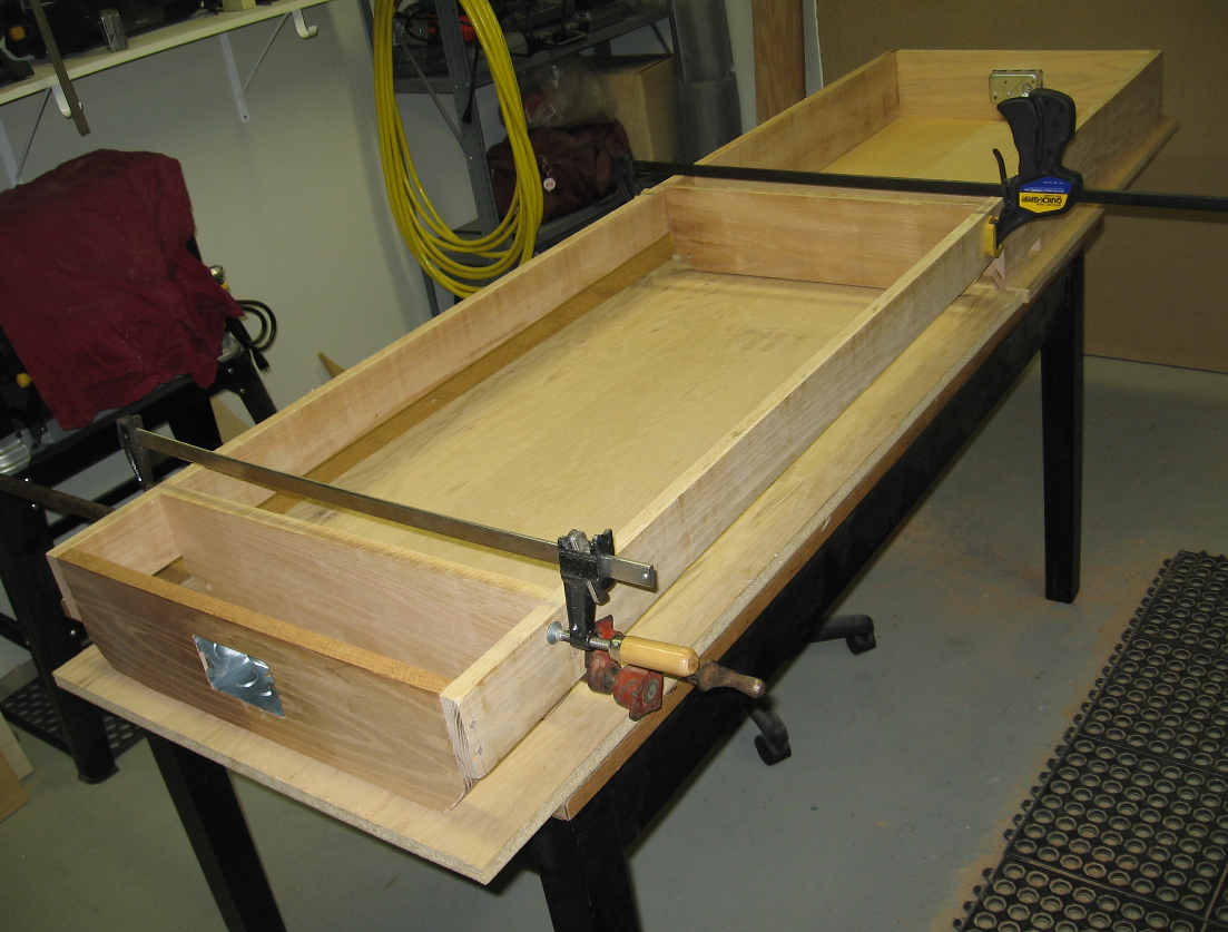
Got about an hour and a half on my table last night and hope to get a little time on it later today.
I managed to put the two electrical boxes in the ends and assembly the far end piece.
Some pics below.
I'd like to get the legs assembled and reference sub top on today.
Possibly mount some of the lift mechanism.
We will have to wait and see how the days work plays out
Alan
-
Thank you Don.
I'll be watching for your model posts

I initially used the traditional WL and longitudinal section views for checking and caught quite a bit but the final slow spinning and studying of the light reflection off the copper tone looking for dark spots was the final step that seems to have caught it all for me
The reflection off the copper tone is similar to the zebra stripe effect but was easier for me to understand.
I am not certain how a plank thickness changes anything but we each have to do what we have to and as I said I'll be watching.
Seems I also needed to walk away for a few weeks as I couldn't "see" anything... like I had blinders on.
I also went back and restudy each frame sketch, found minor line spacing issues and made numerous corrections.
Having said all that it all seems a wee bit excessive and possibly OCD (or is that CDO) for the drastically reduced scale model but the need was stronger than me. It is not like my making adjustments after I've built the model is going to help me at all.
Going out to buy some rose bushes to replace those that didn't survive the winter, plant them and what we bought last weekend ... and cut that darned grass again!
-
now that is interesting
 never saw this before
 -
possibly a cannon ball indentation!

-
Druxey: You think I can sneak anything past "she who must be obeyed"???
I know you are married and I'll bet after all those wonderful years you still can't get anything past her.
Alan
-
Hexnut: The fun left a long time ago with fairing the 3D hull. I just couldn't let it beat me.

As I came back refreshed and could see errors again I will admit some "fun" was brought back to it.
Druxey: I have a similar issue with the floor timber height measurement stated in the contract and feel I should likely stick to the contract and ignore the penned notation
I spent about 2 hours making nit picky fine adjustments to the upper portion
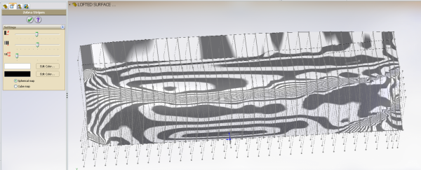
Unsurpressed the loft feature to show the new shape in 3D and slowly spun it about looking for shadows pin pointing blemishes
Cleaned them all up ... I cannot find any more in that manner
Turned on the zebra view and changed it to Spherical Map (wish I had noticed it before) and the image is below
At this point I am ready to move on. (hurray!!)
Alan
- hexnut, Elmer Cornish and Don9of11
-
3
-


CHARLIE by AON - FINISHED - RESTORATION - schooner
in - Build logs for subjects built 1901 - Present Day
Posted
I set the hull upside down on graph paper and centred the stern to the bow using a square.
I then marked reference (station?) lines at 1" intervals onto the hull and graph paper
Now I have the top profile on paper and reference marks on the hull
The model is 6-3/4" wide x 30-7/8" long (171 mm x 784 mm)
I then got out my trusty chalk line and established a centreline along the bottom
I drilled three tiny shallow holes on the chalk line as it will rub away
This is my permanent (until covered) reference for the centreline
My next step (tomorrow?) will be to use my profile gauge along the underside of the hull to trace the shape to transfer to a template.
I did take some photos (to be posted later today) but have to get ready for my day job now.
Hi Ho, Hi Ho, It's off to work I go............................