Waldemar Posted September 8, 2022 Share #31 Posted September 8, 2022 This is exactly what you have already done, and which can be seen in your post #14. Quote Link to comment Share on other sites More sharing options...
Waldemar Posted September 8, 2022 Share #32 Posted September 8, 2022 (edited) ... and this only confirms that you made the scarf correctly, although perhaps somewhat unconsciously. 🙂 Edited September 8, 2022 by Waldemar KrisWood and mtaylor 2 Quote Link to comment Share on other sites More sharing options...
Waldemar Posted September 9, 2022 Share #33 Posted September 9, 2022 However, on balance, I would tend to follow Kevin's advice to simply fake the scarphs to avoid complicating the task. These scarphs are not desirable or essential elements per se, but just means to an end, i.e. combining small elements into larger ones. And they could have been located almost anywhere along the keel length, depending on the available material. mtaylor 1 Quote Link to comment Share on other sites More sharing options...
KrisWood Posted September 10, 2022 Author Share #34 Posted September 10, 2022 The main reason I've kept them so far has been the scale I'm working at (1:25) makes it very difficult to find wood long enough to make the keel in a single piece. I'd still need to make scarfs for the stems anyway. 🤷♂️ mtaylor 1 Quote Link to comment Share on other sites More sharing options...
KrisWood Posted September 12, 2022 Author Share #35 Posted September 12, 2022 Next problem with my plans. I've got three kinds of errors: 1. Scanning / scaling artifacts: A number of the published resources were either scanned from paper or rescaled from digital files to the point where the numbers are too distorted/pixelated to read 2. Measurement errors: A number of the measurements in the resource materials disagree with each other within 1cm. There's no apparent way to tell which are the right ones 3. Typos: Unavoidable in any materials with this many numbers in them I've got a situation where some lines by the numbers are 1cm away from where they are drawn. Furthermore the numbers are out of fair. So I'm stuck with a choice, draw the lines as drawn, or draw them as calculated and try to fair them? What would you do? mtaylor 1 Quote Link to comment Share on other sites More sharing options...
Kevin-the-lubber Posted September 12, 2022 Share #36 Posted September 12, 2022 My view is this: whatever looks most right and gets you closest to what you want with the least amount of work. In other words, the line of least resistance. I don't know about you but I find fairing on a computer to be much more difficult than if I was doing it to a piece of timber. No options here to run your hand along it with your eyes closed, feel the little bumps. druxey and mtaylor 2 Quote Current builds: 1) HMS Victory 1:100 (Heller) https://modelshipworld.com/topic/23247-hms-victory-by-kevin-the-lubber-heller-1100-plastic-with-3d-printed-additions/ 2) Bluenose II 1:100 (Billing) - paused, not in the mood https://modelshipworld.com/topic/30694-billing-bluenose-ii-1100-no600-by-kevin-the-lubber/ 3) Cutty Sark 1:96 Revell https://modelshipworld.com/topic/30964-cutty-sark-by-kevin-the-lubber-revell-196 Stash: Revell Cutty Sark 1/96 (a spare for later) Revell Beagle 1/96 (unlikely to ever get built!) Revell Kearsage 1/96 (can't wait to get started on this) Revell Constitution 1/96 If at first you don't succeed, buy some more tools. Link to comment Share on other sites More sharing options...
Lieste Posted September 12, 2022 Share #37 Posted September 12, 2022 A mm is an inch in scale... I would note that there is a considerable asymmetry in her lines, in excess of several inches for knees, and having a visibly different line for the wales port and starboard, as well as for the location of the knees relative to station lines. Get it fair and 'close' trying to be 'perfect' is unlikely to be 'more authentic' to the original building practice. mtaylor and druxey 2 Quote Link to comment Share on other sites More sharing options...
KrisWood Posted September 12, 2022 Author Share #38 Posted September 12, 2022 (edited) I think she got it closer than the museum reconstruction. The original conservator didn't take into account that the keel had been flattened by the burial mound settling on top of it for a thousand years. He also assumed the decks/oar holes were flat, when they actually line up better if curved. The knees were broken in multiple places so any reconstruction is somewhat guesswork, though the museum display has them shorter than the excavation drawings. (Note, the original conservator also didn't have computers to do wood grain analysis to figure out which way the curves of broken pieces went together) Anyway, like the two of you suggested, I'm thinking I'll end up with something that looks very much like the oseberg ship, which does not agree 100% with the plans. Edited September 13, 2022 by KrisWood mtaylor 1 Quote Link to comment Share on other sites More sharing options...
Lieste Posted September 12, 2022 Share #39 Posted September 12, 2022 The Saga Obesberg is a far better sailor than the built 'as displayed' Dronningen which drove under when tested under sail because of her 'too flat' keel sheer and the 'too narrow' thwarts in the damaged bow area of the museum article. With the original form approximated as closely as is possible using rigorous archaeology and practical model and modern and 'model' 3d reconstructions and simulation the Saga Oseberg is a much more successful sailer, capable of tacking with apparent ease, as well as riding on her own bow wave and semi-planing under sail at speed. druxey, mtaylor and KrisWood 3 Quote Link to comment Share on other sites More sharing options...
KrisWood Posted September 13, 2022 Author Share #40 Posted September 13, 2022 The curved stems of Saga Oseberg pull the bow up slightly. The straighter, narrower stems of Dronningen caused it to dive naturally at the bow. 😣 Part of the problem with Dronningen was that it was built from Lundin's 1957 plans. Lundin didn't have access to measurements of all parts so he had to guess more. druxey and mtaylor 2 Quote Link to comment Share on other sites More sharing options...
Waldemar Posted September 13, 2022 Share #41 Posted September 13, 2022 You have already received good advice above. Even the best reconstruction models made by archaeologists are always only an approximation, and a model 100% identical to the original has yet to be built, if that is at all possible. That said, first and foremost you have to decide for yourself whether you want to build a model closer to the archaeological interpretation or a nicer looking display model. As you have already discovered, archaeological documentation is not always precise and you have to interpret. Where numerical data and graphics conflict, I tend to favour the numbers, but not in a fundamentalist way. A lot depends on the context and your choices about the nature of the model. druxey, mtaylor and KrisWood 3 Quote Link to comment Share on other sites More sharing options...
Waldemar Posted September 13, 2022 Share #42 Posted September 13, 2022 In such dilemmas, it is also very important for me to answer the question: what was the intention of the original builders? As opposed to what they happened to come up with. druxey, KrisWood and mtaylor 3 Quote Link to comment Share on other sites More sharing options...
Waldemar Posted September 13, 2022 Share #43 Posted September 13, 2022 (edited) And also try to look at it from the point of view of an archaeologist doing the documentation. To take my example: I once took measurements of gun barrels in a museum and discovered that, among many other errors, they are not round in cross-section but oval. It would have been unnecessary nonsense to try to reflect this irregular deformation in the dimensioned line drawings. I averaged the measurements, noting this fact in the description, and gave the measurement deviations.... Now ask yourself: how accurately would I want to make a scale model of such a deformed barrel (diameter deformations up to 8 mm and irregular along the length of the barrel). Take into account that all the cannon barrels were deformed in many different ways, even those of the same series. Edited September 13, 2022 by Waldemar KrisWood, druxey and mtaylor 3 Quote Link to comment Share on other sites More sharing options...
KrisWood Posted September 16, 2022 Author Share #44 Posted September 16, 2022 Anyone want to help draw the stems? I'm having a heck of a time getting the thickness of all the parts correct. Most of the dimensions are on page 28 of "Rekonstruktion af Osebergskibet" Bind II. The dimensions for "Snit E" are on page 27. mtaylor 1 Quote Link to comment Share on other sites More sharing options...
KrisWood Posted September 17, 2022 Author Share #45 Posted September 17, 2022 (edited) Here's all the relevant details. Bischoff reconstruction on the left, Johannessen reconstruction on the right. How in the world would you model the transition from stem to stem-top? Edited September 17, 2022 by KrisWood mtaylor 1 Quote Link to comment Share on other sites More sharing options...
KrisWood Posted September 17, 2022 Author Share #46 Posted September 17, 2022 Hmm when saving it as a jpg it blurred the numbers horribly Quote Link to comment Share on other sites More sharing options...
Waldemar Posted September 17, 2022 Share #47 Posted September 17, 2022 (edited) The size of the inserted bitmaps into the posts is reduced (probably to a maximum of 1440 pixels of the longer side). Yes, these are quite nasty shapes to model, but possible. Try it this way, but your initial polysurface needs to be closed (for better clarity and less working time a straight element in this sample): This is not the only way, but probably the most convenient. Edited September 17, 2022 by Waldemar KrisWood and mtaylor 2 Quote Link to comment Share on other sites More sharing options...
Waldemar Posted September 17, 2022 Share #48 Posted September 17, 2022 Or, when exporting pages from a PDF document as bitmaps, set higher resolutions. KrisWood and mtaylor 2 Quote Link to comment Share on other sites More sharing options...
KrisWood Posted September 17, 2022 Author Share #49 Posted September 17, 2022 8 hours ago, Waldemar said: The size of the inserted bitmaps into the posts is reduced (probably to a maximum of 1440 pixels of the longer side). Yes, these are quite nasty shapes to model, but possible. Try it this way, but your initial polysurface needs to be closed (for better clarity and less working time a straight element in this sample): This is not the only way, but probably the most convenient. Count me amazed. How do you do that so fast? Are you using Rhino? The rabbets can be modeled more simply as being perpendicular to the inside of the stem and not cut out. That's how they were made on Saga Oseberg. They didn't cut them until they were ready to lay the next plank down, and then they cut it to the depth of that plank. mtaylor 1 Quote Link to comment Share on other sites More sharing options...
Waldemar Posted September 18, 2022 Share #50 Posted September 18, 2022 Yep, for CAD work only Rhino and I like it very much. Of course, my renders were only to show the idea of the proceedings, you choose the exact shape. KrisWood and mtaylor 2 Quote Link to comment Share on other sites More sharing options...
KrisWood Posted September 19, 2022 Author Share #51 Posted September 19, 2022 Ok I'm stumped. I couldn't figure out how to model with solids like you did, so I did it my own way using open curves. I've forgotten how to get solids out of these though.... mtaylor 1 Quote Link to comment Share on other sites More sharing options...
KrisWood Posted September 19, 2022 Author Share #52 Posted September 19, 2022 (edited) Ha. Hahaha. HAHAHAHAHAHAHAHAHAHAHA.... 🤪 I went and added my beautiful, new, mathematically derived lines for the stem back into my guesstimate that I'd made before the new, more detailed plans and numbers were published. All that work and none of the lines moved by more than a centimeter... My old guesstimate was as close as makes no difference at scale... 😆 That said, I guess I'm going back to a previous save and simply converting my files to a card-friendly scale/format... Edit: Also, the way I ended up getting a three dimensional stem-top was to take Johannessen's cross sections and adapt them to Bischoff's numbers, then voila, it matched Saga Oseberg. In doing so, I realized a simple truth about all Oseberg reconstructions. Every last one of them is historically inaccurate. In Mr Finderup's "Saga Oseberg" book, he explains that they ran out of time at the end of the project to fully analyze the remaining fragments of the stem top, so they went with a mathematically derived approximation in a single solid piece, even though the original used multiple pieces. Comparing excavation drawings to both Johannessen's and Bischoff's reconstructions, the original stem top would have been somewhat larger and at a different (somewhat unknowable) angle. Because it makes zero difference to the functioning of the ship, I think Ms Bischoff's approach is the correct one. Johannessen did what looked good for the museum display. Bischoff did what functions given the most probable dimensions of the planks which made up the hull of the ship. Edited September 19, 2022 by KrisWood mtaylor 1 Quote Link to comment Share on other sites More sharing options...
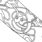
KrisWood Posted September 20, 2022 Author Share #53 Posted September 20, 2022 Drawing the carvings for the first time. I'm going to need to print them on card and then paint over the parts that are too small to cut. It's fun to be doing art instead of math for once on this project. And with that I'd better get some sleep! mtaylor 1 Quote Link to comment Share on other sites More sharing options...
KrisWood Posted September 21, 2022 Author Share #54 Posted September 21, 2022 So many carvings to get into the right format. This will take a while... mtaylor 1 Quote Link to comment Share on other sites More sharing options...
KrisWood Posted September 23, 2022 Author Share #55 Posted September 23, 2022 Finished the port-side fore-stem carvings, moving on to the "tingl". mtaylor, jchbeiner and Waldemar 1 2 Quote Link to comment Share on other sites More sharing options...
Waldemar Posted September 23, 2022 Share #56 Posted September 23, 2022 Bravo! mtaylor and KrisWood 2 Quote Link to comment Share on other sites More sharing options...
KrisWood Posted September 30, 2022 Author Share #57 Posted September 30, 2022 Question: Is there a good (free?) automated tool for importing ship plan drawings from any raster format into any vector format which can be imported into Rhino? I've tried a number of methods but they all end up with curves drawn as bubbles around the black lines rather than through the middle of the black lines. I've got photoshop if anyone knows of a method there as well. mtaylor 1 Quote Link to comment Share on other sites More sharing options...
KrisWood Posted October 1, 2022 Author Share #58 Posted October 1, 2022 (edited) And next question is, depth of rabbets, drawn in CAD or just the placement of the rabbets and cut them to depth physically when building? Edit: Here's a fun diagram to explain how to draw the depth of the rabbets on any Viking ship that has them. It's actually surprisingly easy. The following is a cross section of the stem at a point where I have no numbers beyond those calculated from the documentation for top and bottom width of the keel / stems. The plans have lines for the top and bottom of the rabbet and the bottom of the keel in profile view. I've drawn these as horizontal lines in RED. Given the measurements of the widths from the documentation, I can now make a trapezoid shape connecting the dots, which I've done in BLUE. Next I draw the depth of the keel as two circles, centered at the intersection of the red lines with the blue line, which I've drawn in GREEN. I'm not bothering to taper my planks, so my circles have a diameter of 2.5cm along the entire length of the keel / stems. To get the correct ANGLE of the rabbets, draw a line connecting the two circles from the intersection of the top circle with the top red line to the tangent of the bottom circle, which will give a perfect right angle to the bottom of the rabbet, drawn in BLACK. Edited October 1, 2022 by KrisWood mtaylor 1 Quote Link to comment Share on other sites More sharing options...
KrisWood Posted October 1, 2022 Author Share #59 Posted October 1, 2022 (edited) Now to do the aft stem and then I'll be ready to slice it into printable layers. Edit: oh wait, I still need to figure out how to project the carvings onto the stems... Edited October 1, 2022 by KrisWood mtaylor 1 Quote Link to comment Share on other sites More sharing options...
KrisWood Posted October 3, 2022 Author Share #60 Posted October 3, 2022 Two questions for you all... 1. How do you project curves onto a surface in Rhino? 2. My reference materials from the stems are, I think, based on Johannessen's reconstruction drawings and Sofie Krafft's detailed drawings of the carvings. They do not line up with Ms Bischoff's reconstruction. In my game modeling days in 3D Studio Max there was a tool called Free Form Deformation that could scoot curves into place en-mass in situations like this. Is there an equivalent in Rhino? BenD 1 Quote Link to comment Share on other sites More sharing options...

Recommended Posts
Join the conversation
You can post now and register later. If you have an account, sign in now to post with your account.