James H
-
Posts
5,517 -
Joined
-
Last visited
Content Type
Profiles
Forums
Gallery
Events
Everything posted by James H
-
Kit review Full Metal Beam Engine Steam Engine (RETROL) - EngineDIY
James H replied to James H's topic in Non ship-related reviews
For me, it did start to move, but not not enough to start its cycle. I needed to push the flywheel to get momentum. I presume the initial movement was because the cylinder was at the start of its travel (at bottom of stroke), and needed external momentum to begin that cycle. -
Kit review Full Metal Beam Engine Steam Engine (RETROL) - EngineDIY
James H replied to James H's topic in Non ship-related reviews
They sure are. Was a big surprise to me as the last two I bought for the school I work, were between £150 and £200, possibly. Certainly nowhere near £400. And let's be honest, they aren't great technical creations with their soldered joints and thin boiler jacket, faux chimney and rickety construction. This new one feels incredibly robust and 'sure' in its operation. If anyone wants a nice discount on this or any other model engine from EngineDIY, just use the voucher code: JAMESHATCH -
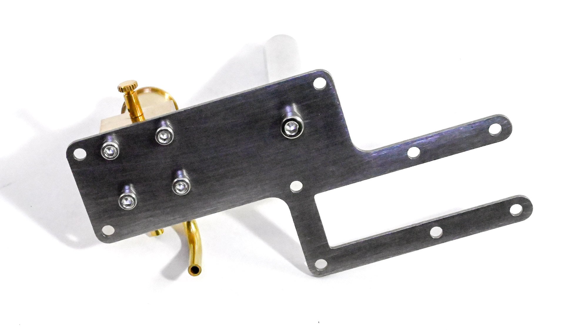
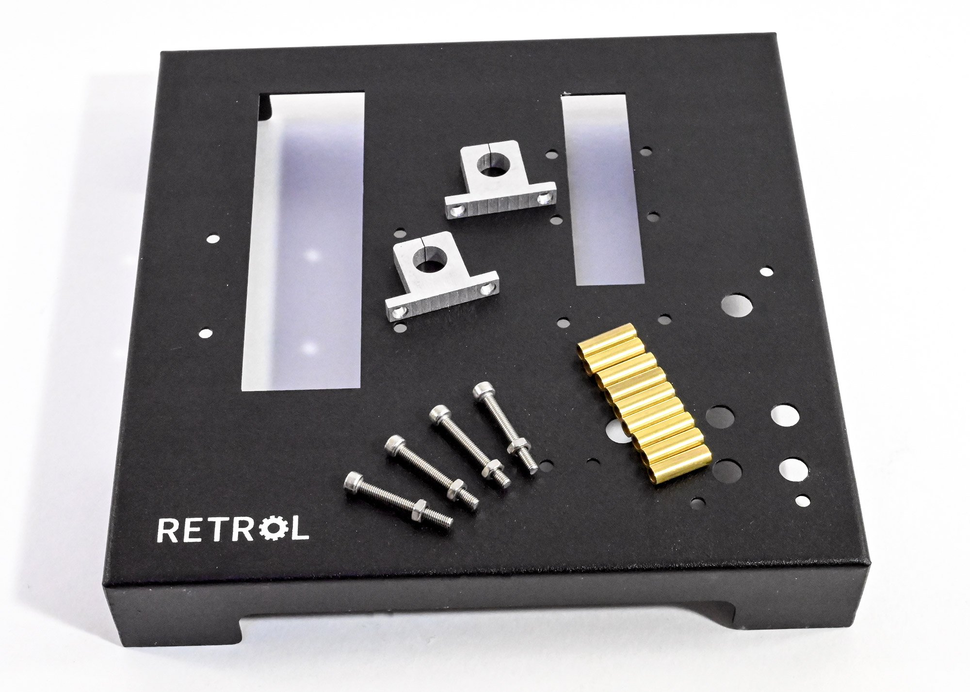
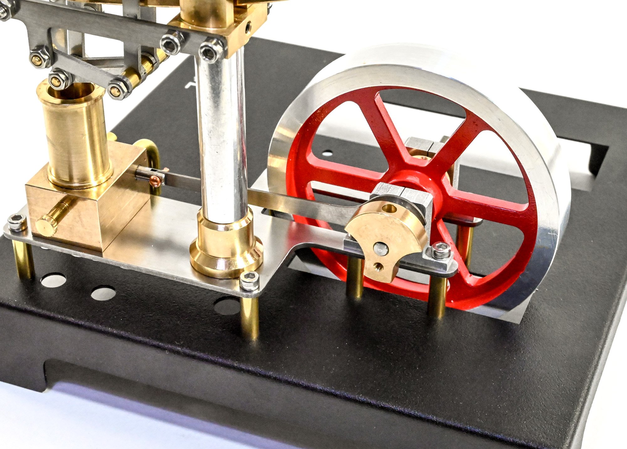
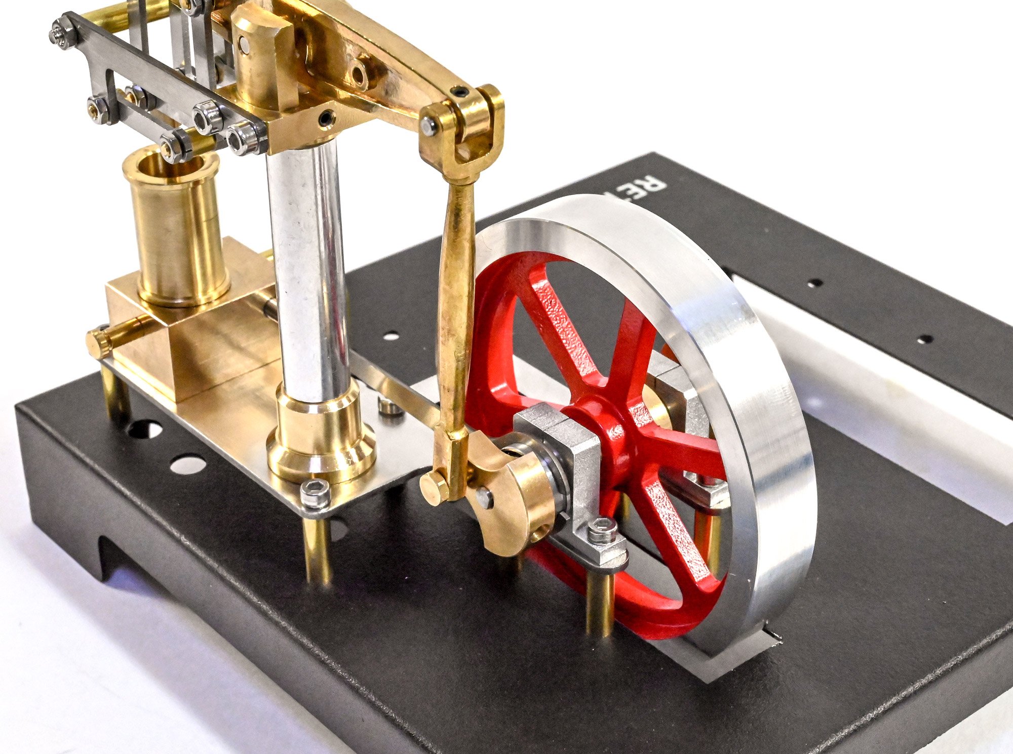
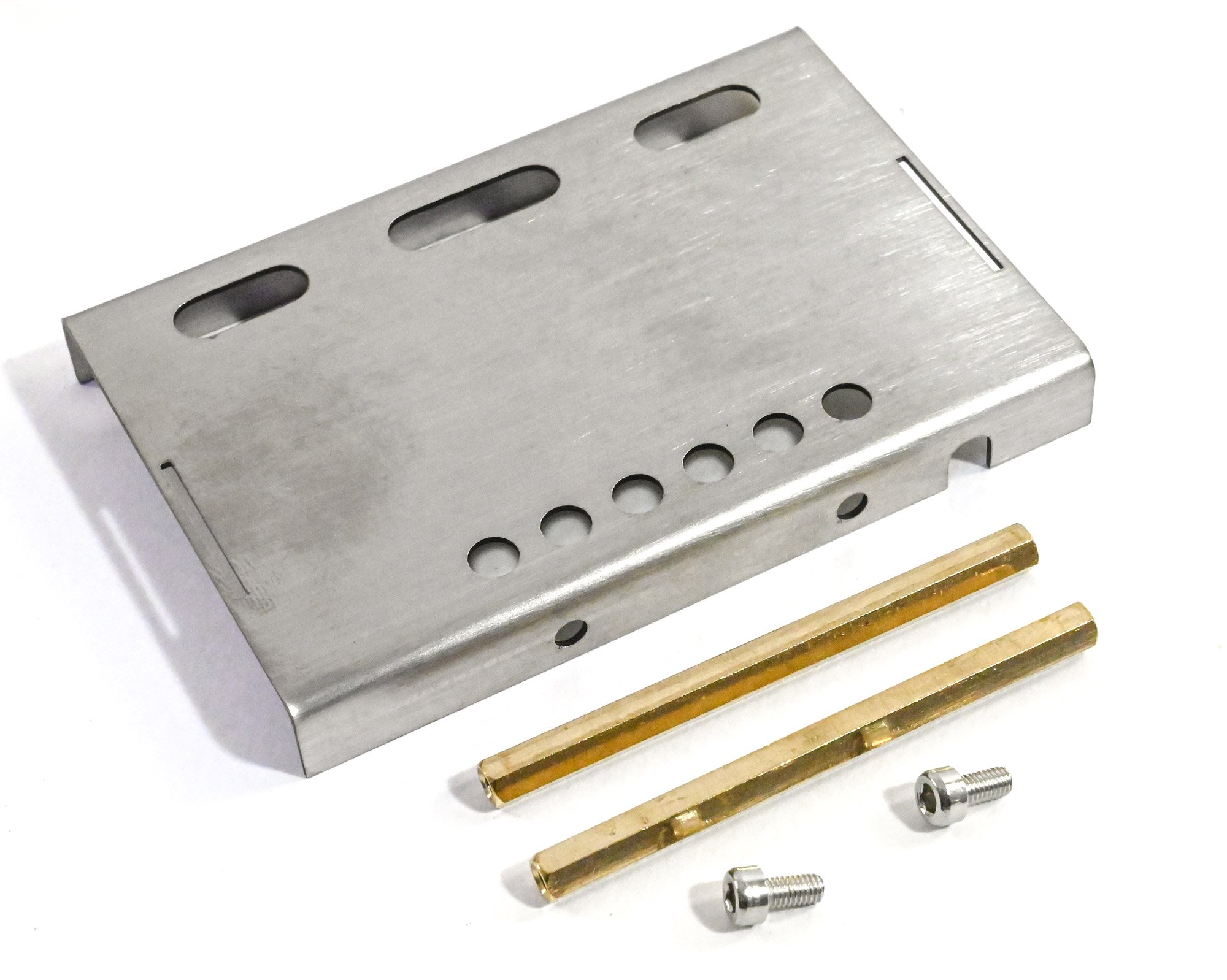
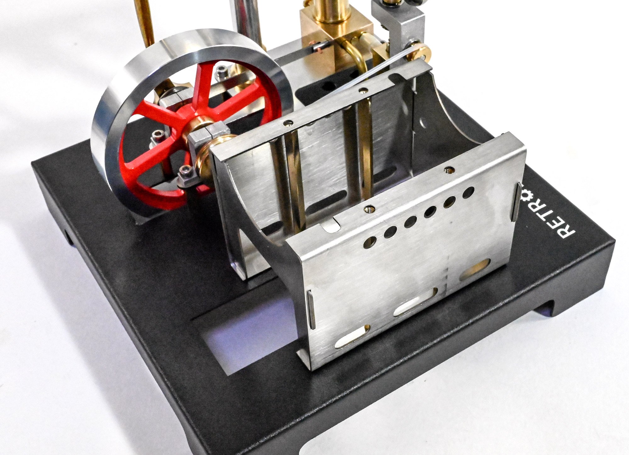
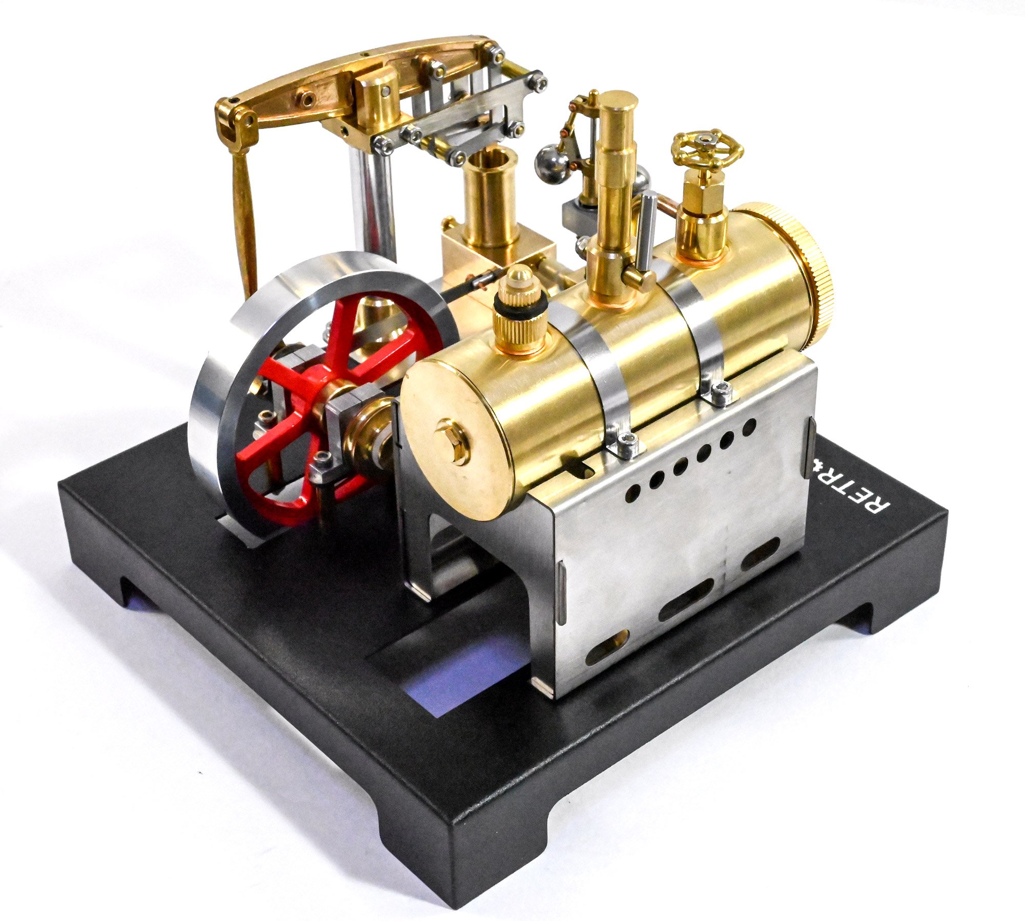
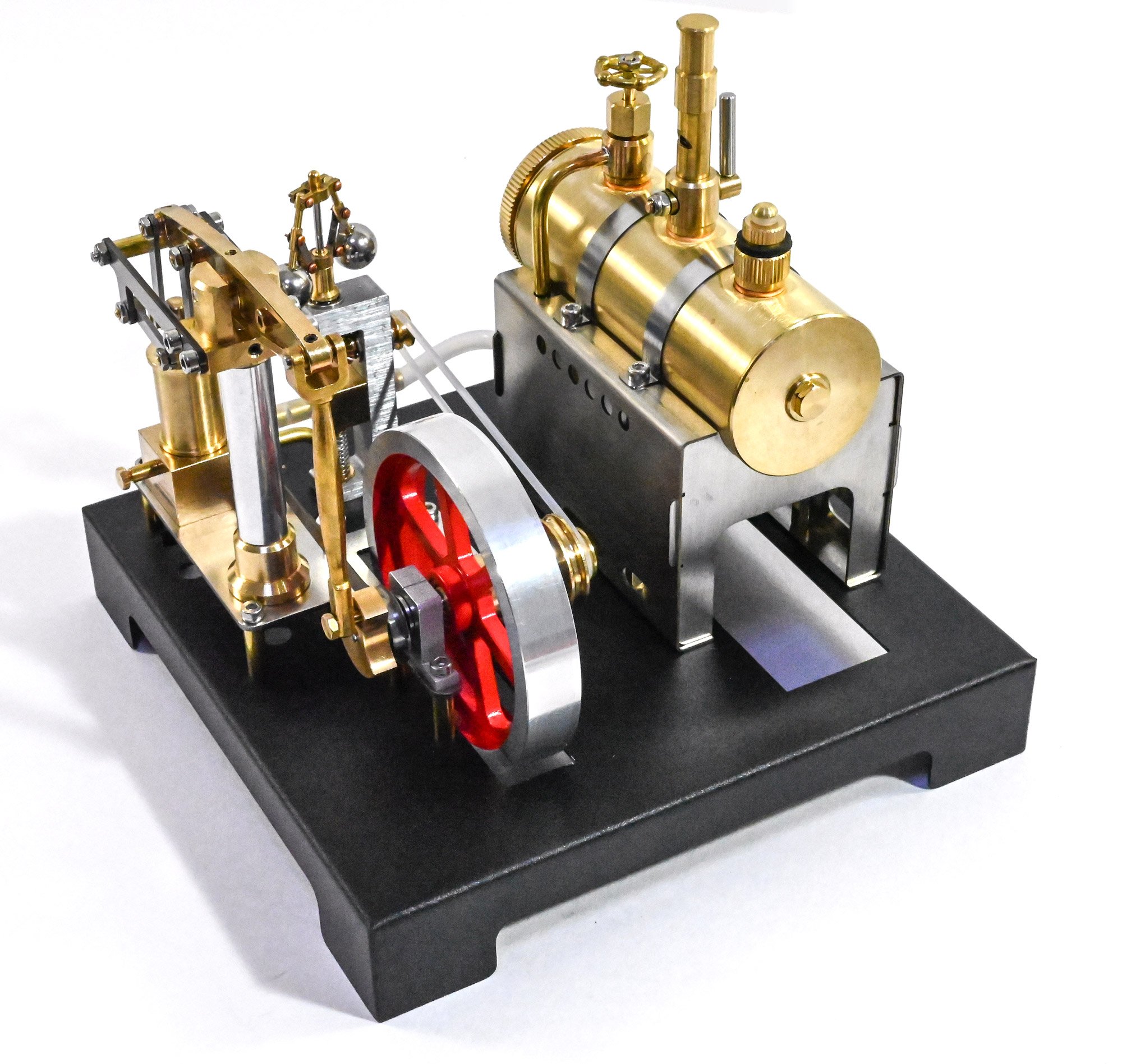
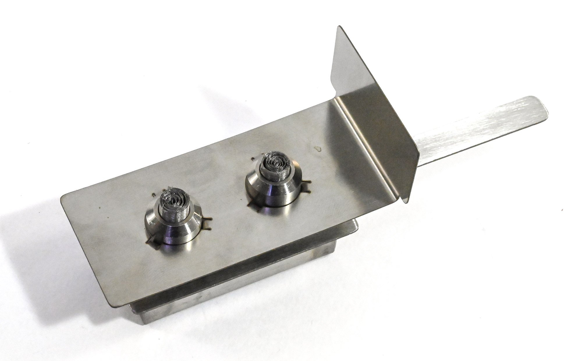
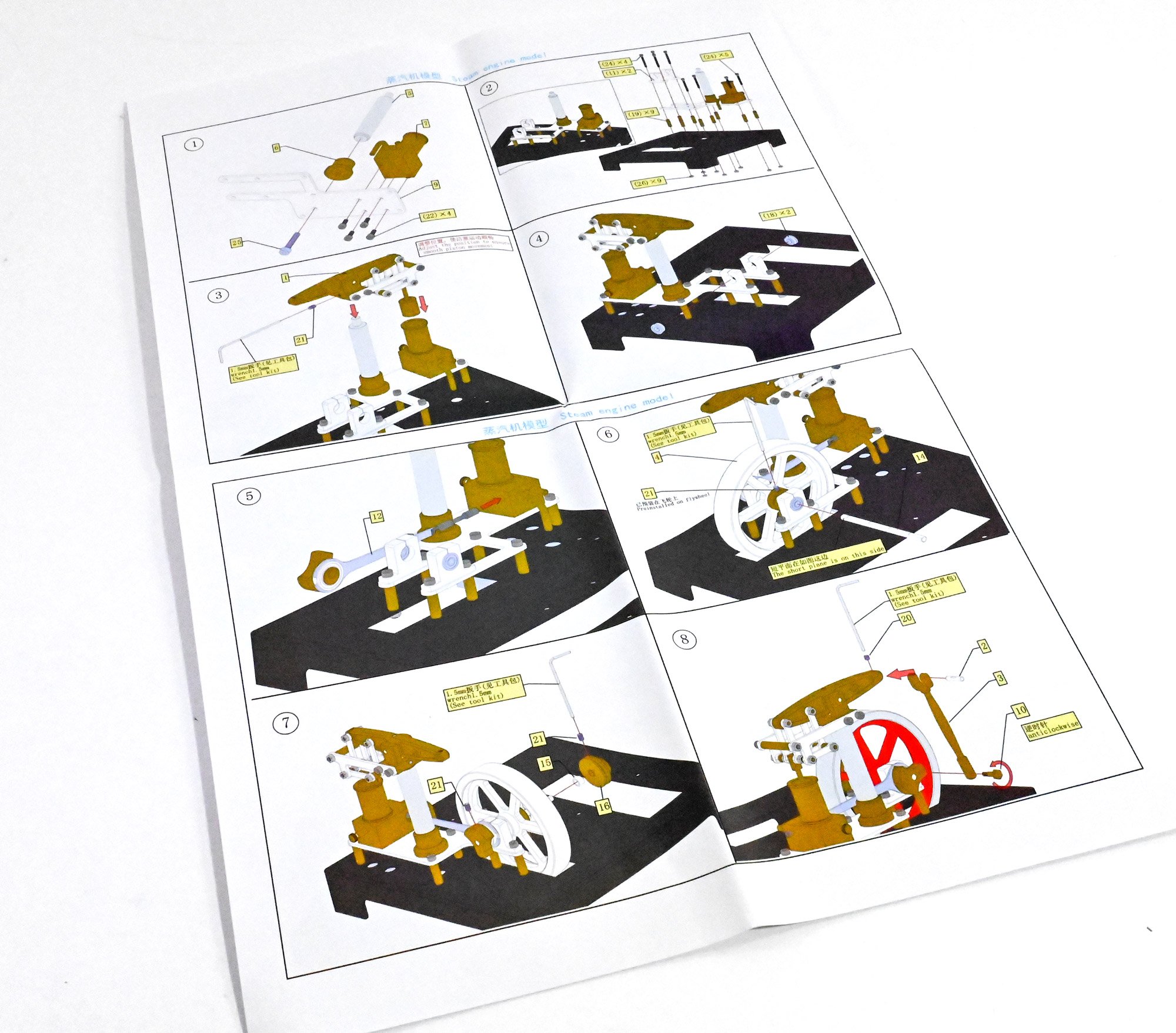
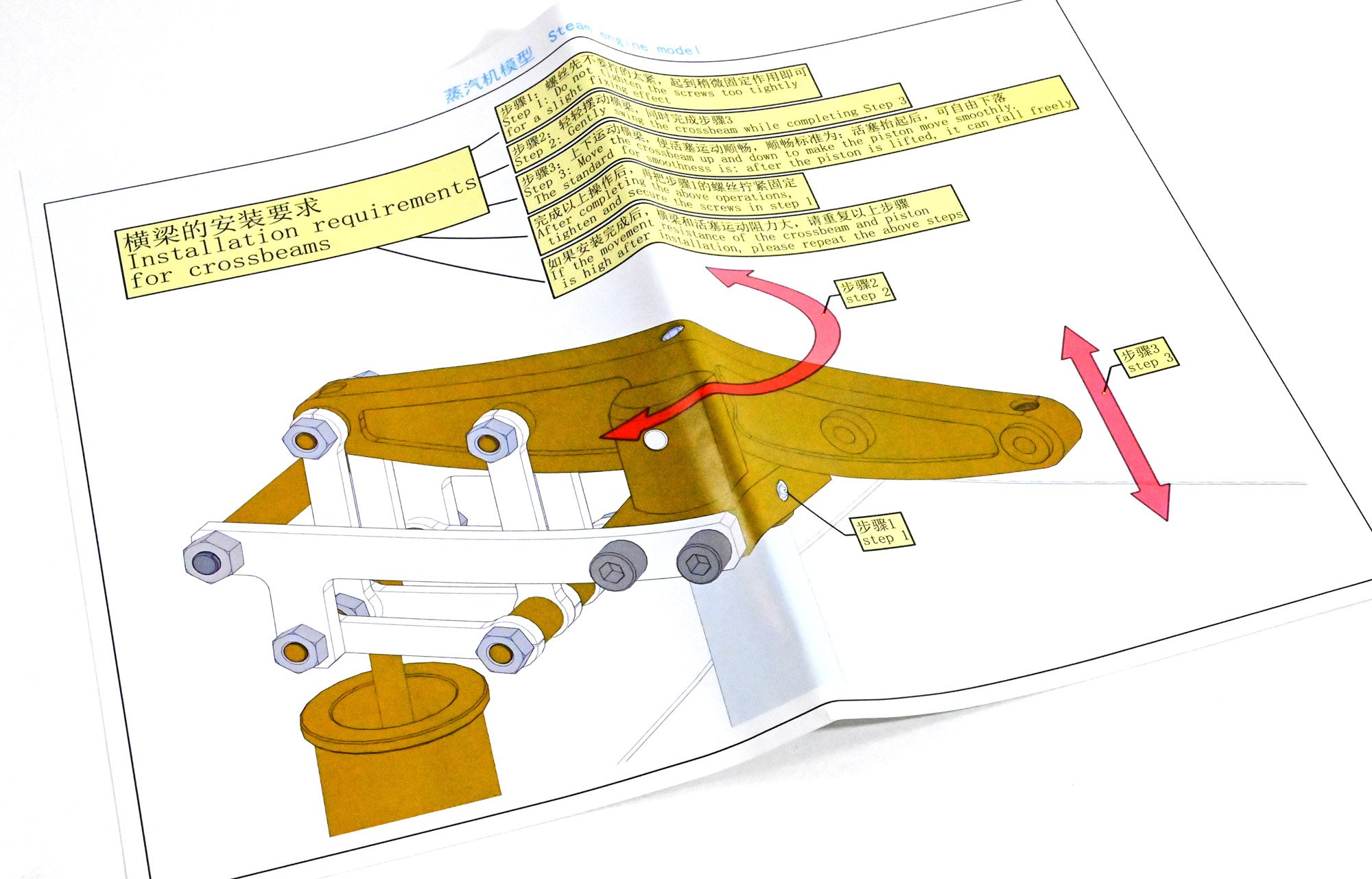
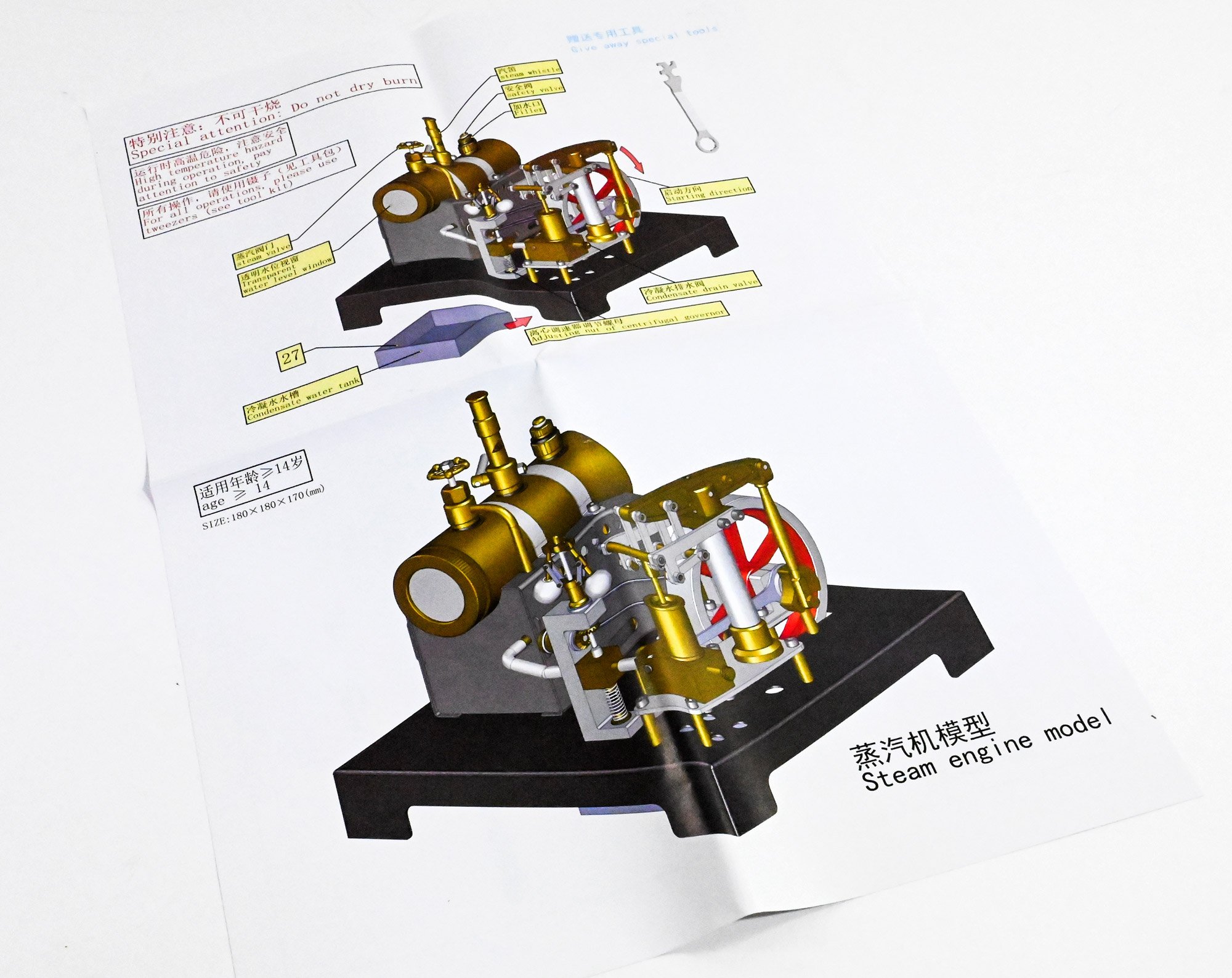
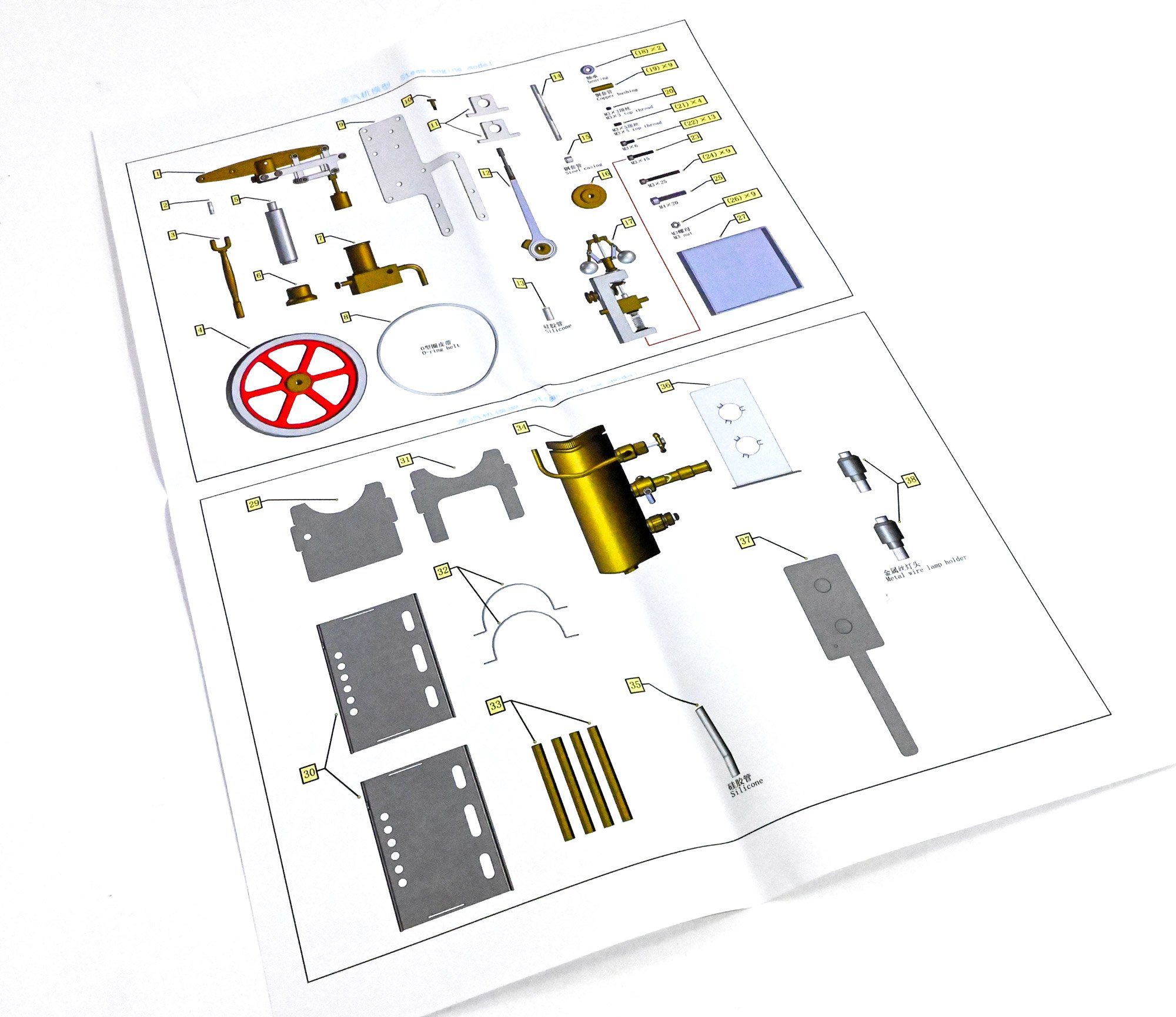
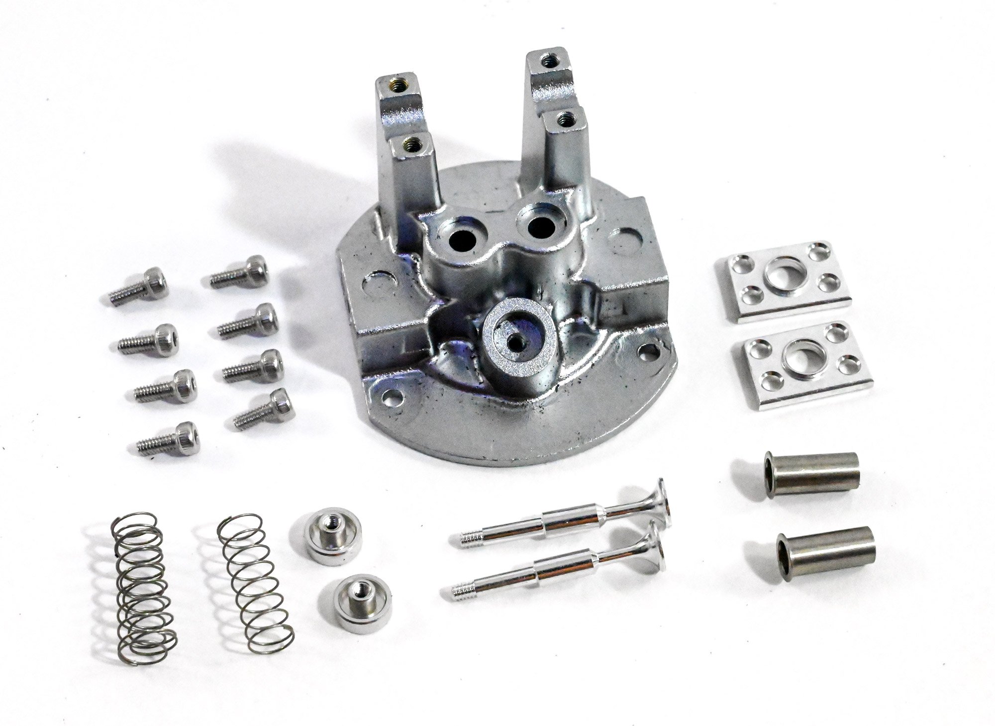
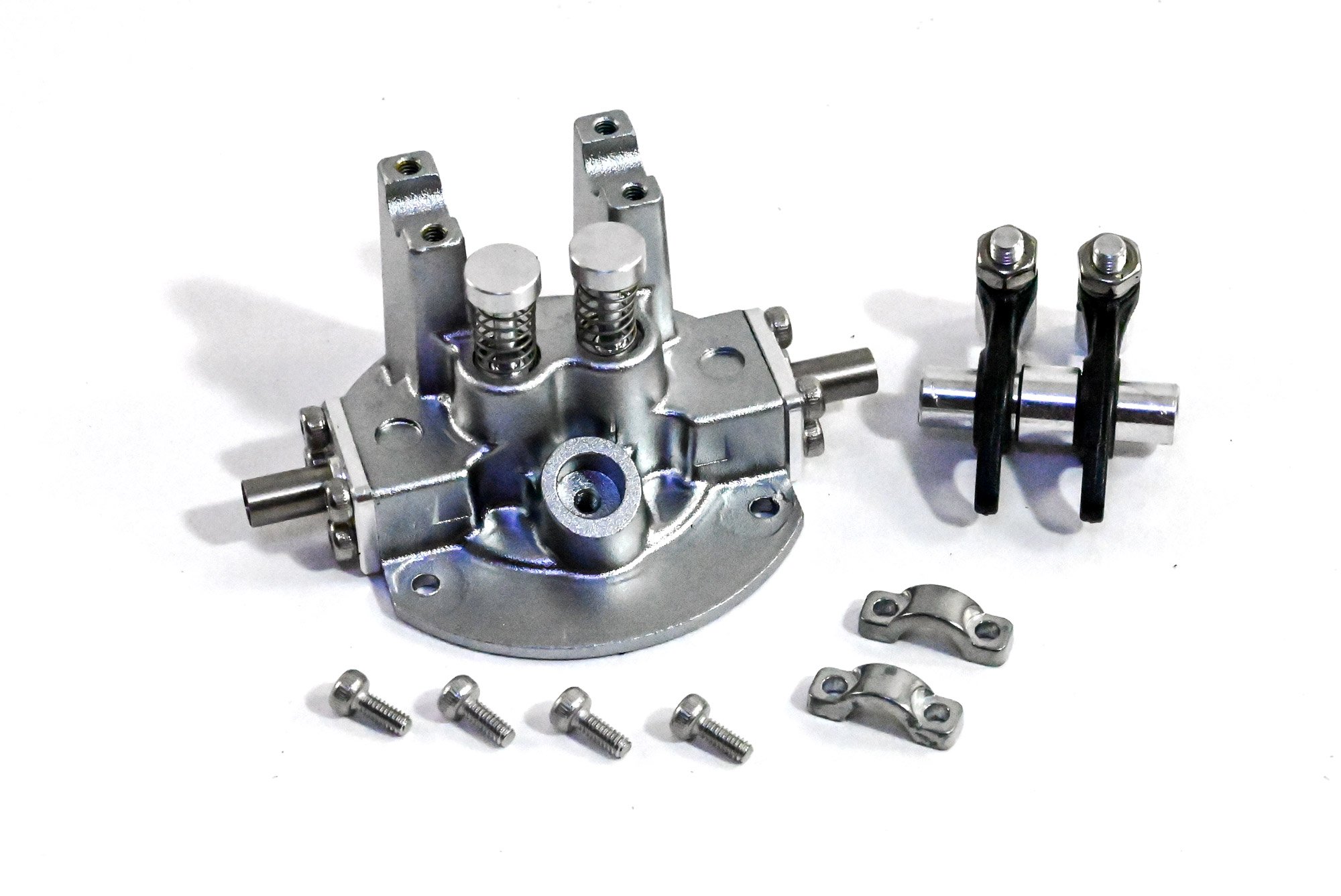
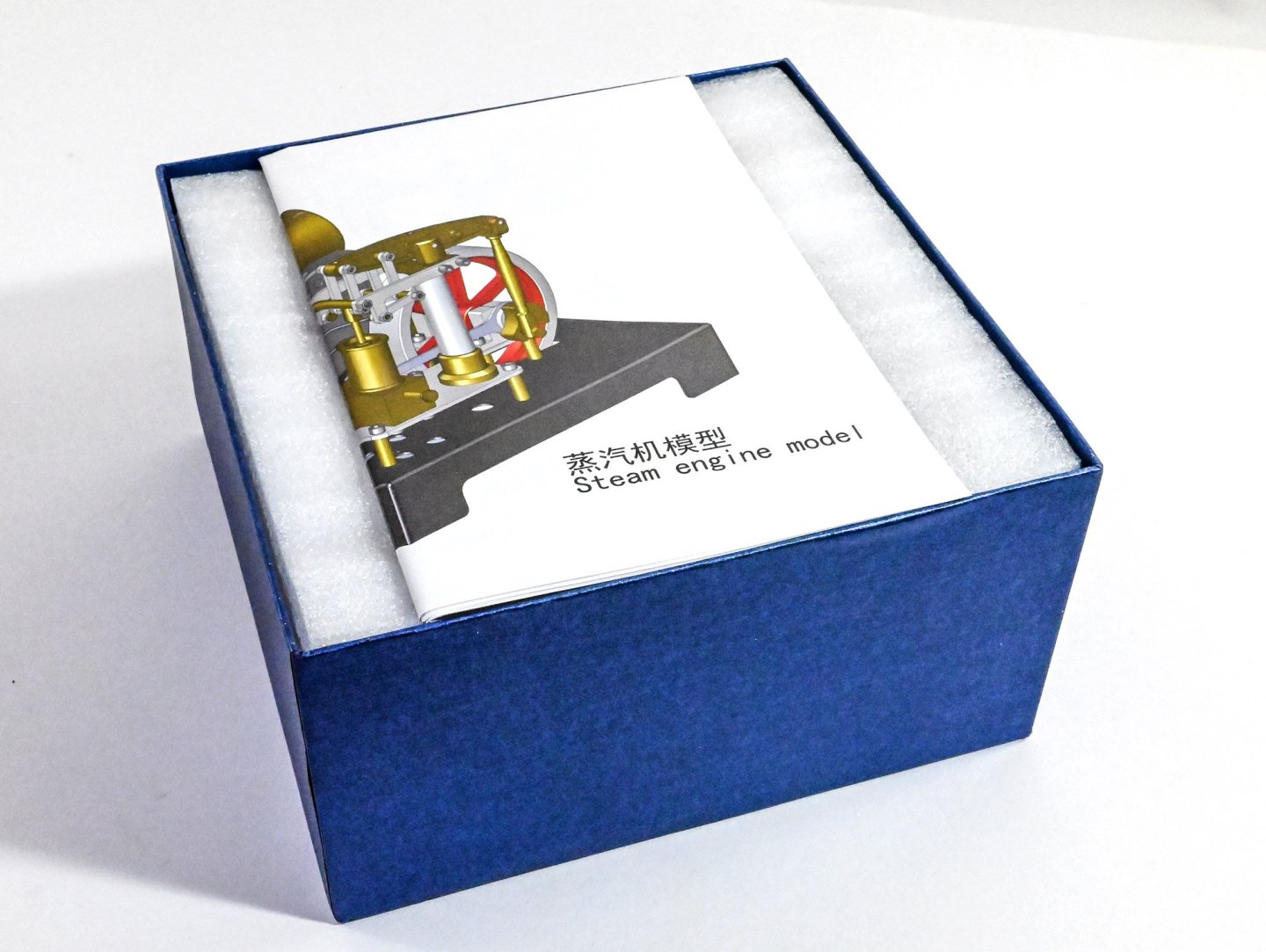
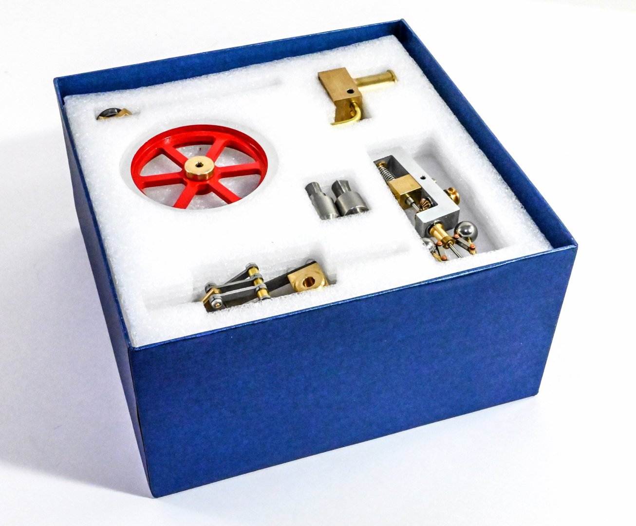
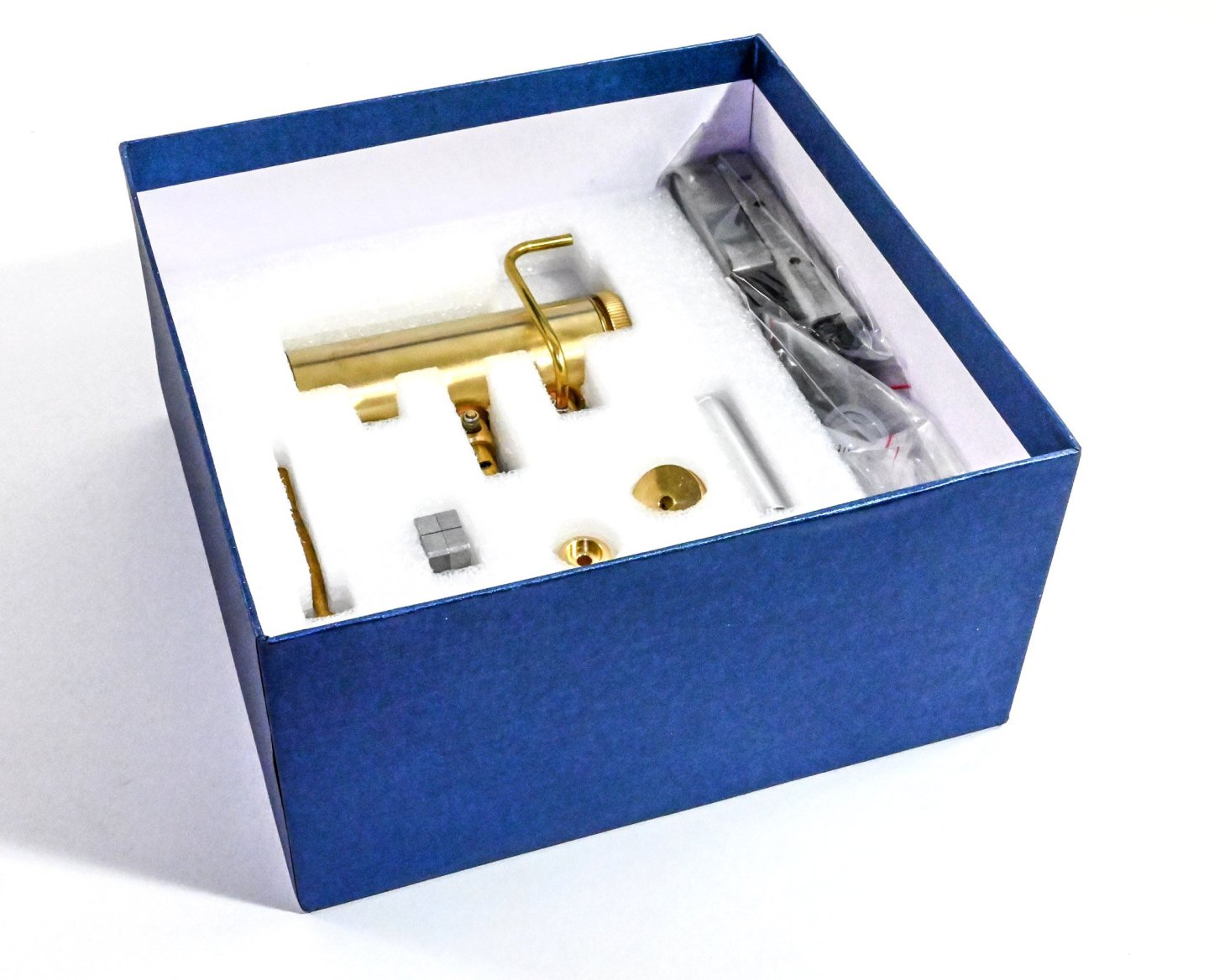
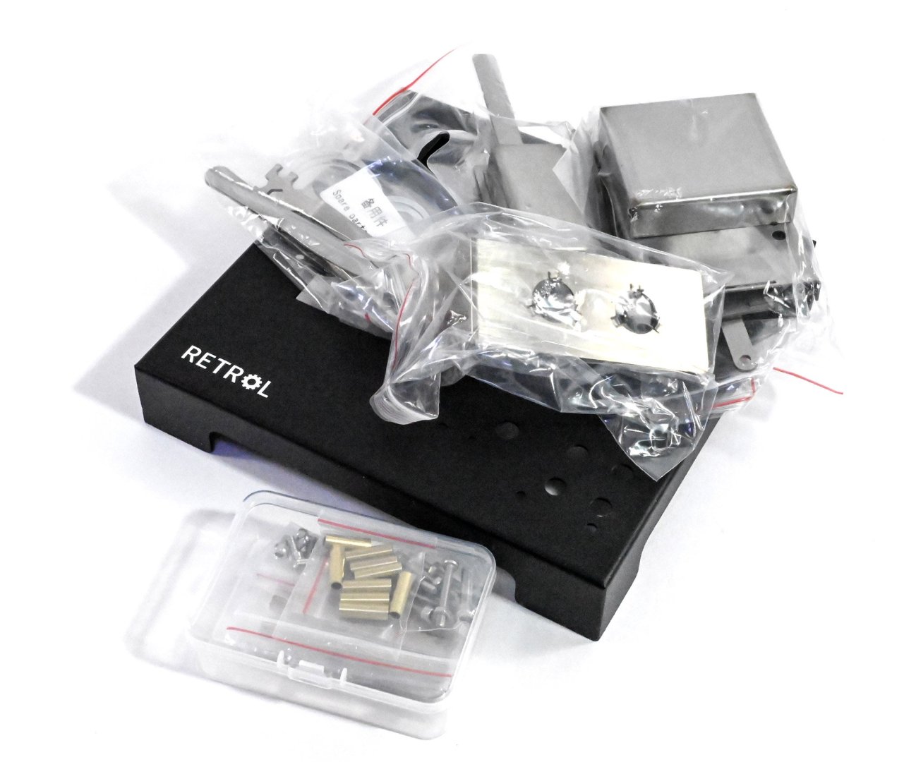
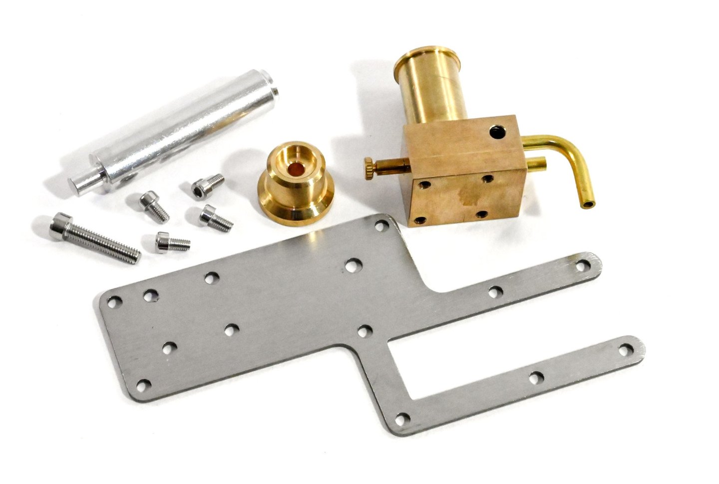
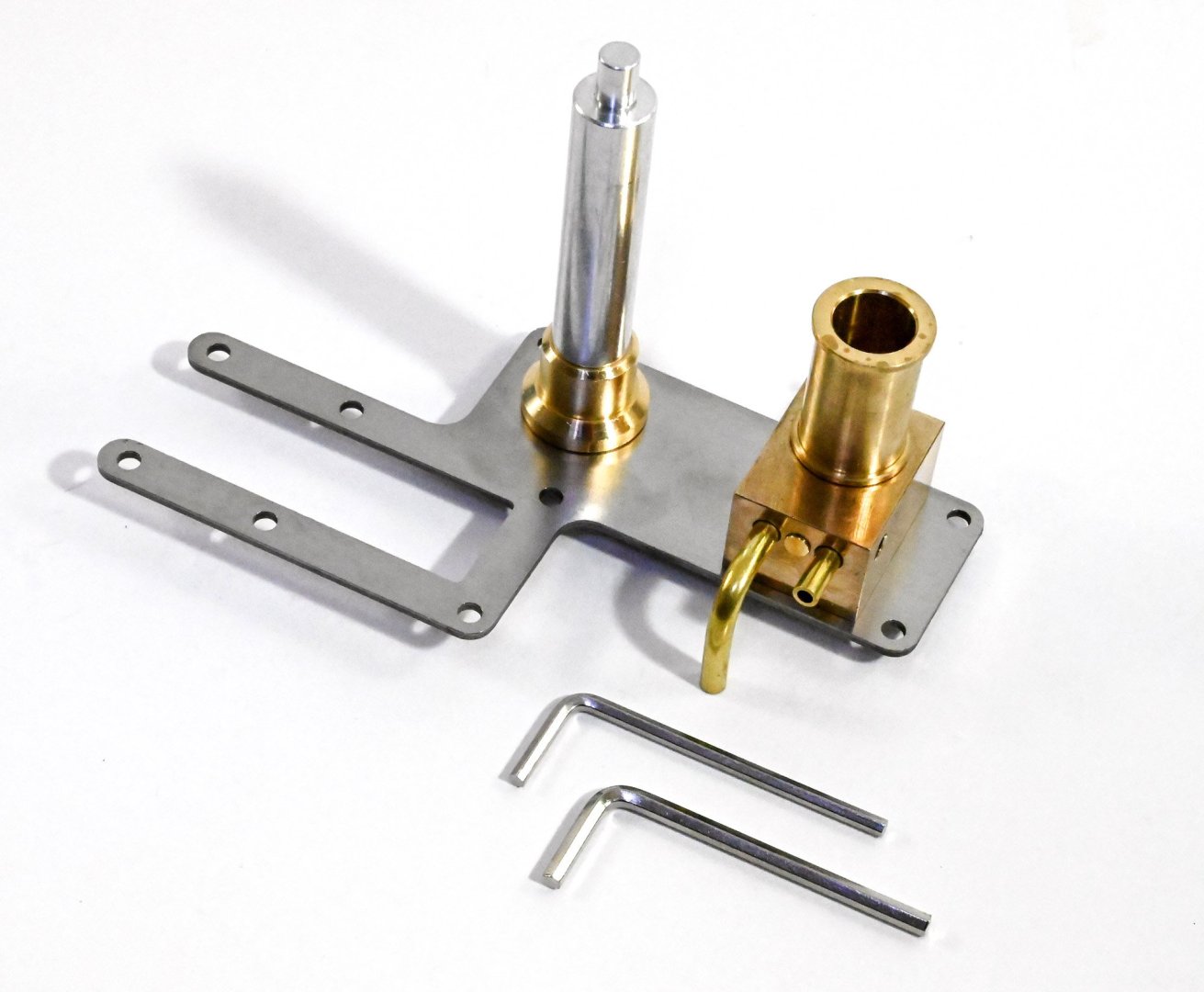
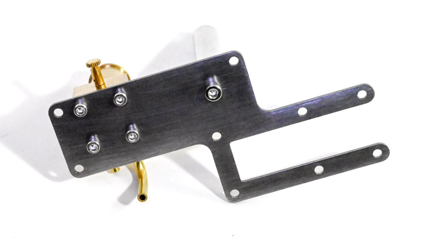
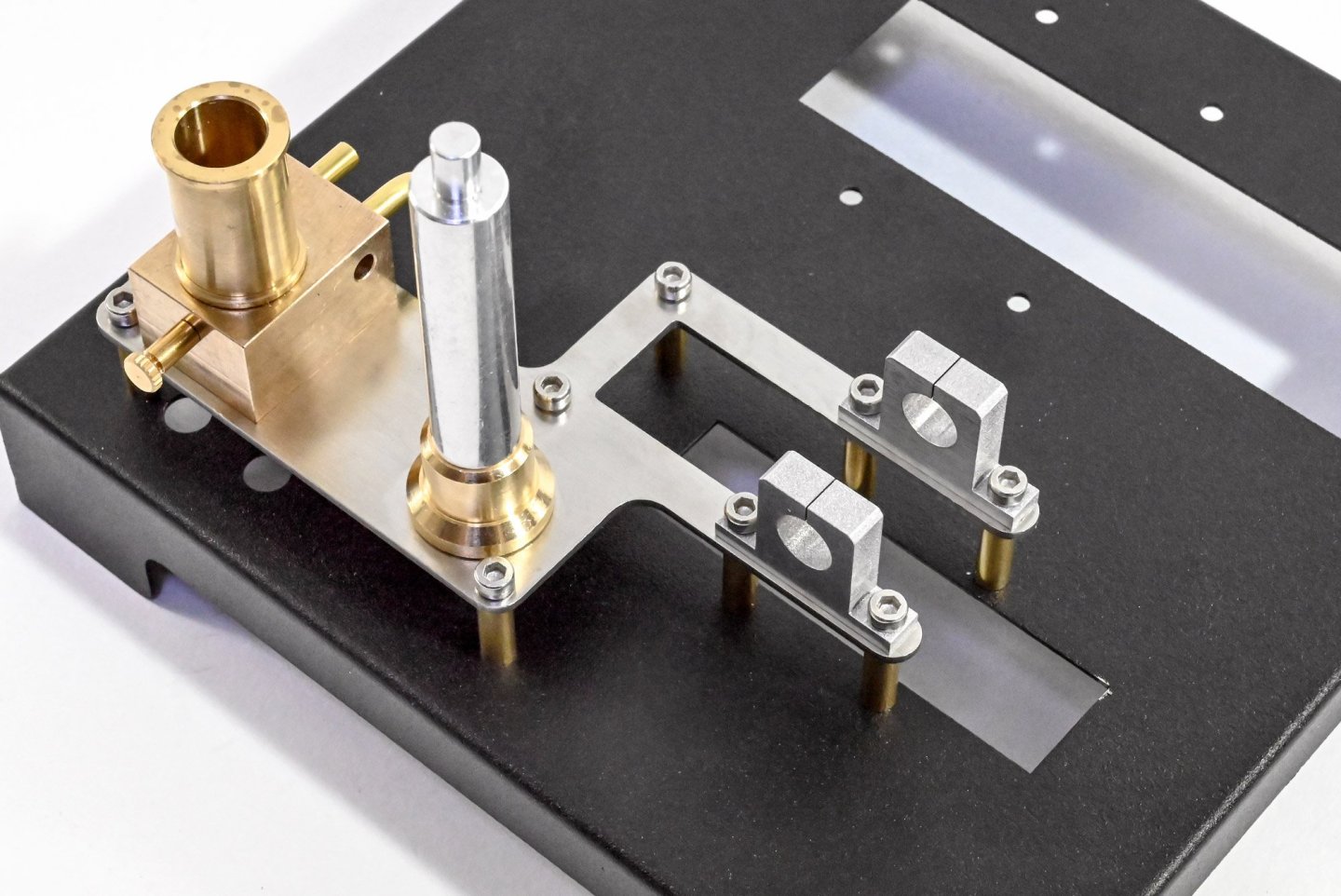
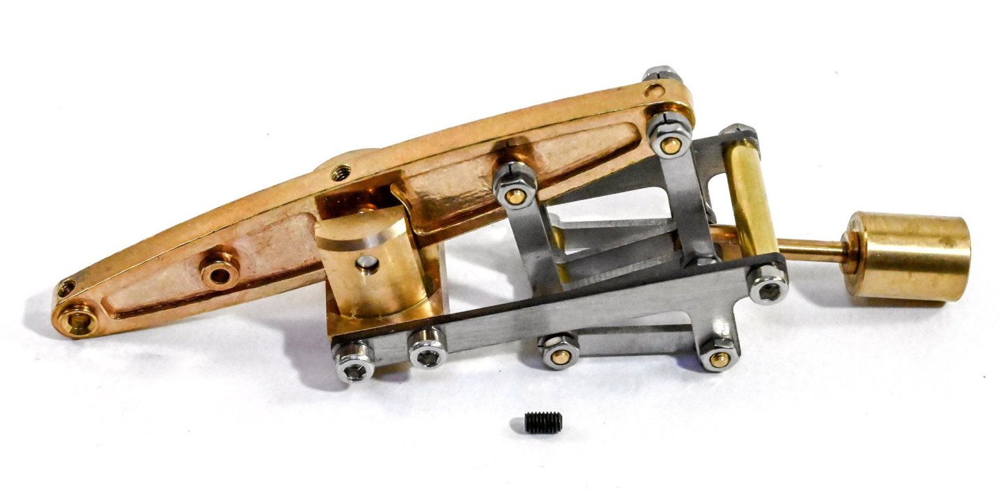
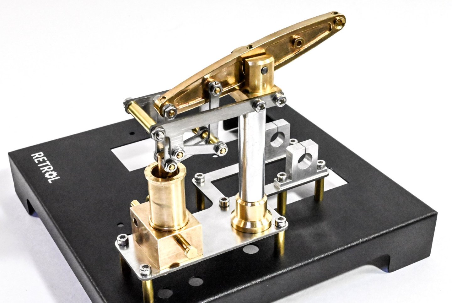
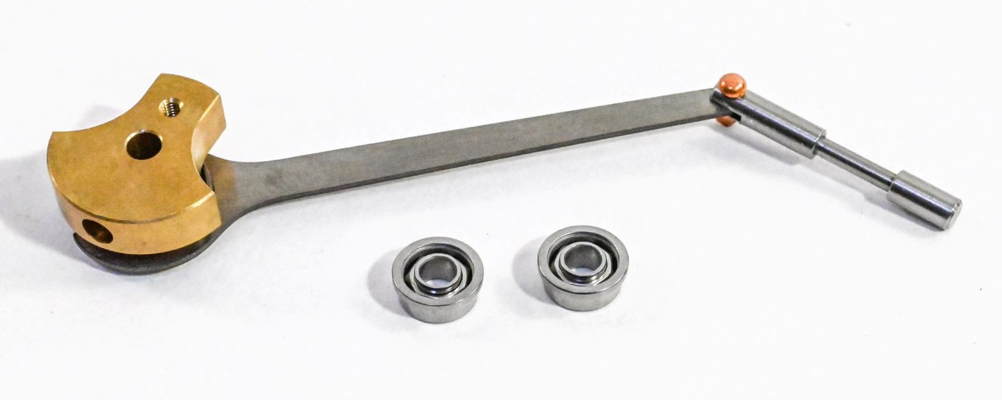
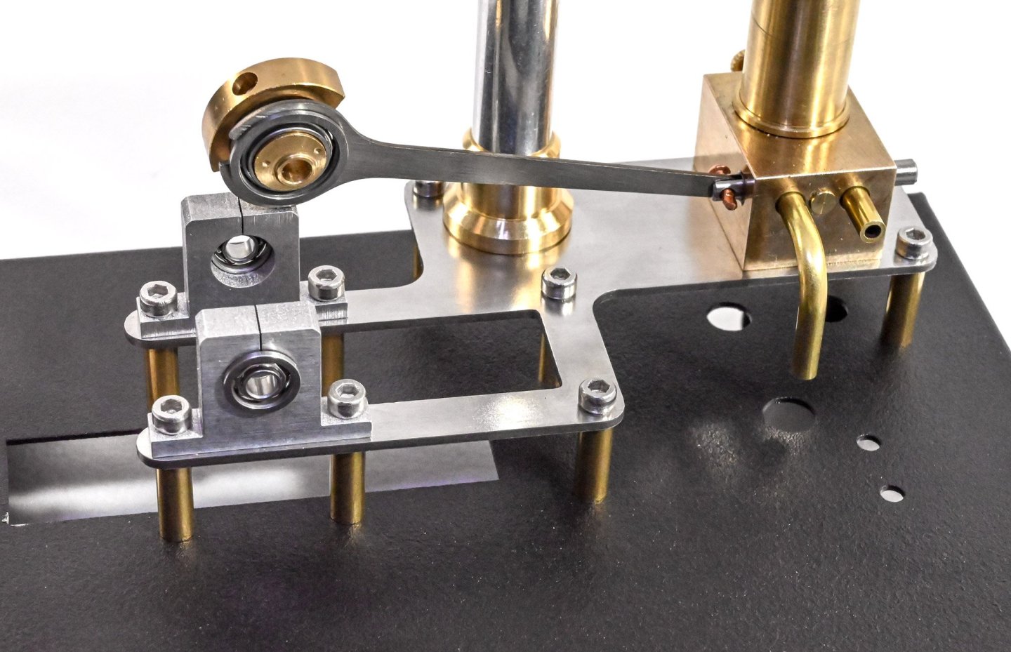
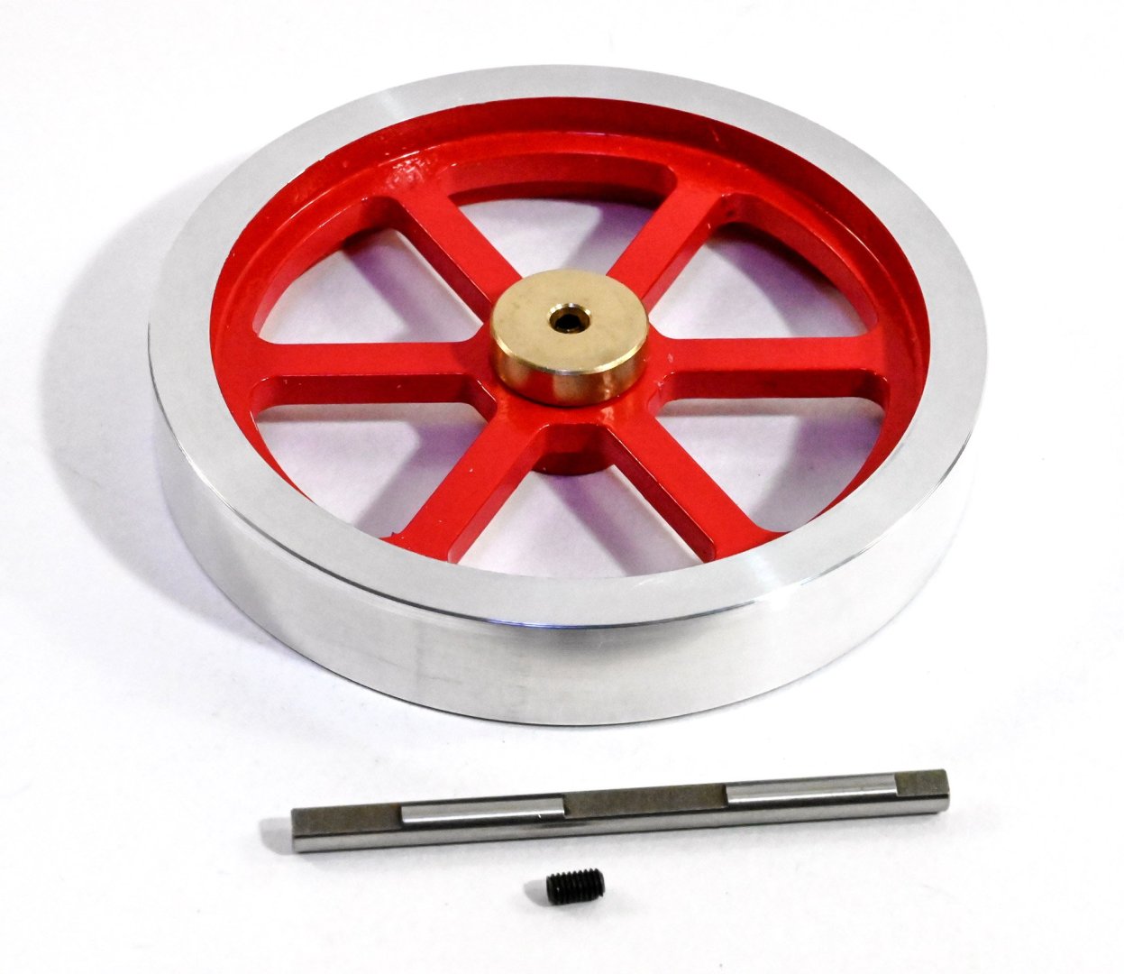
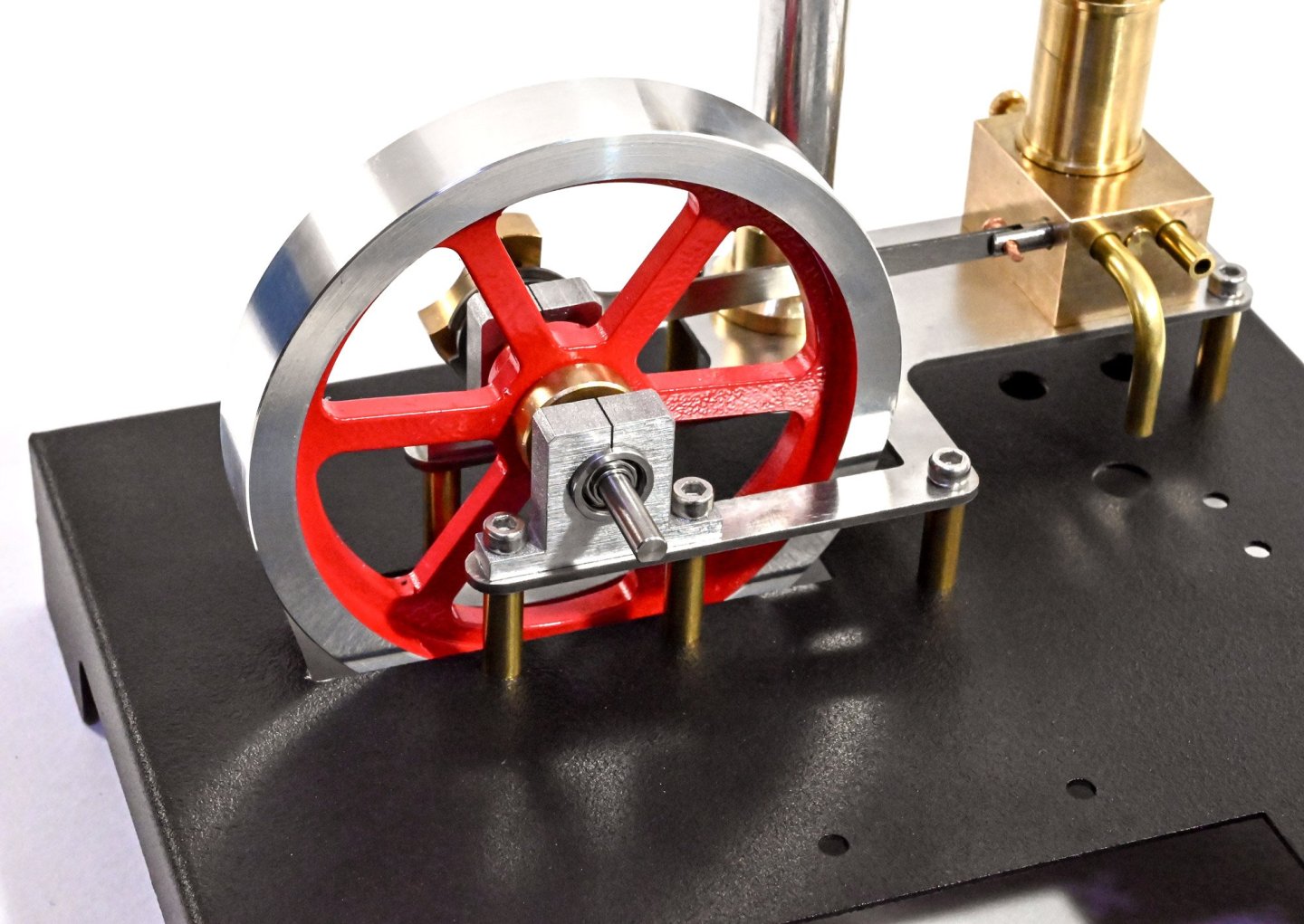
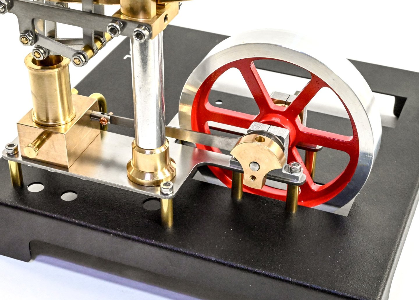
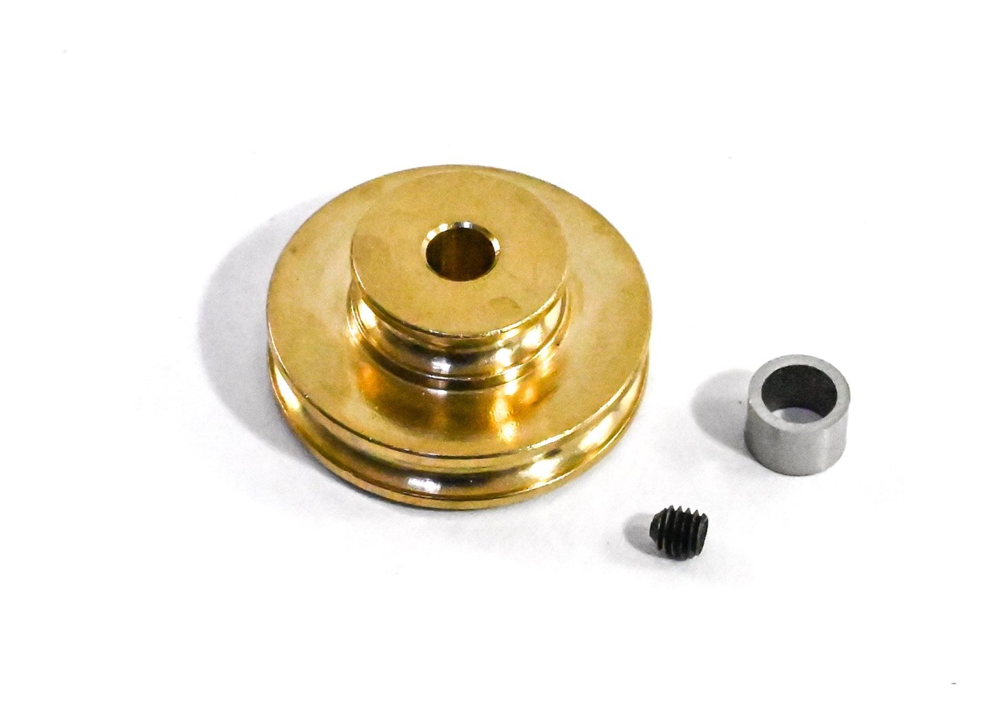
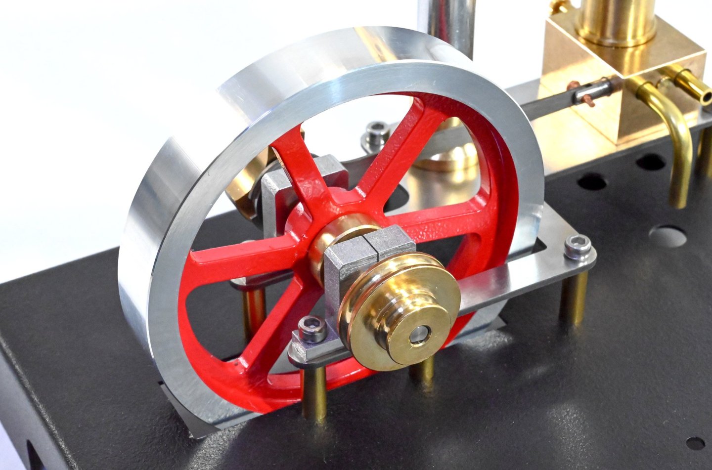
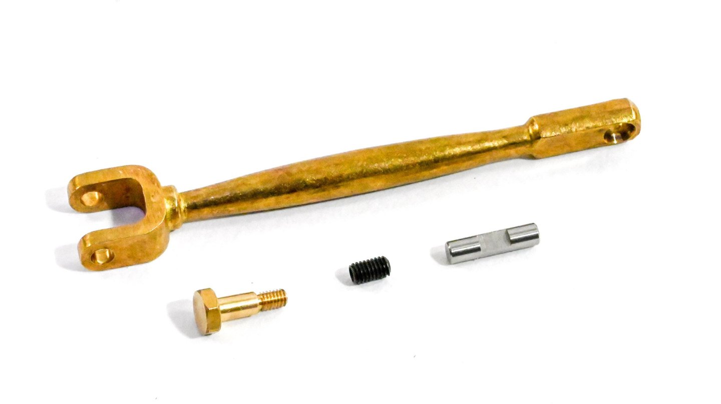
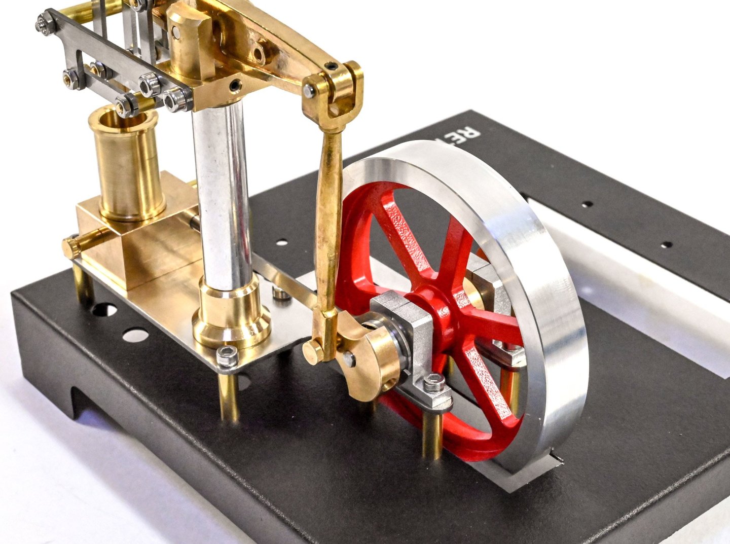
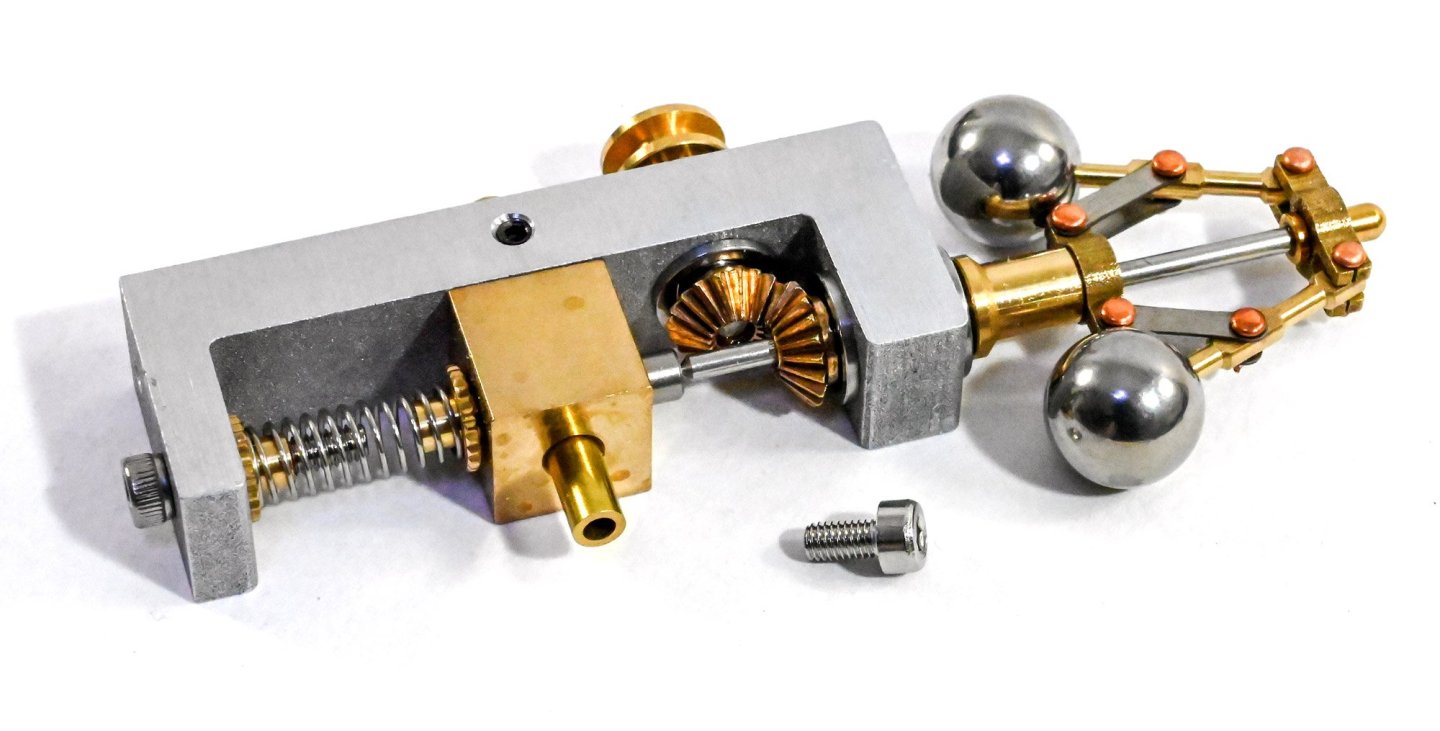
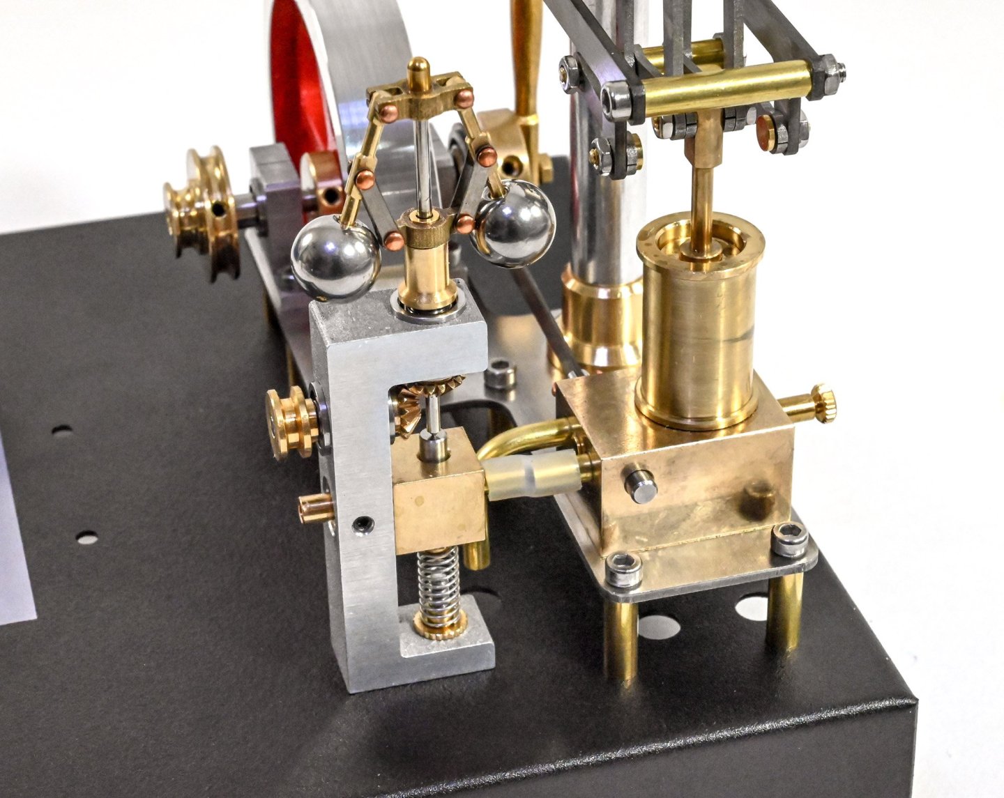
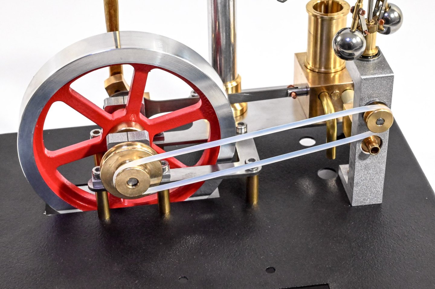
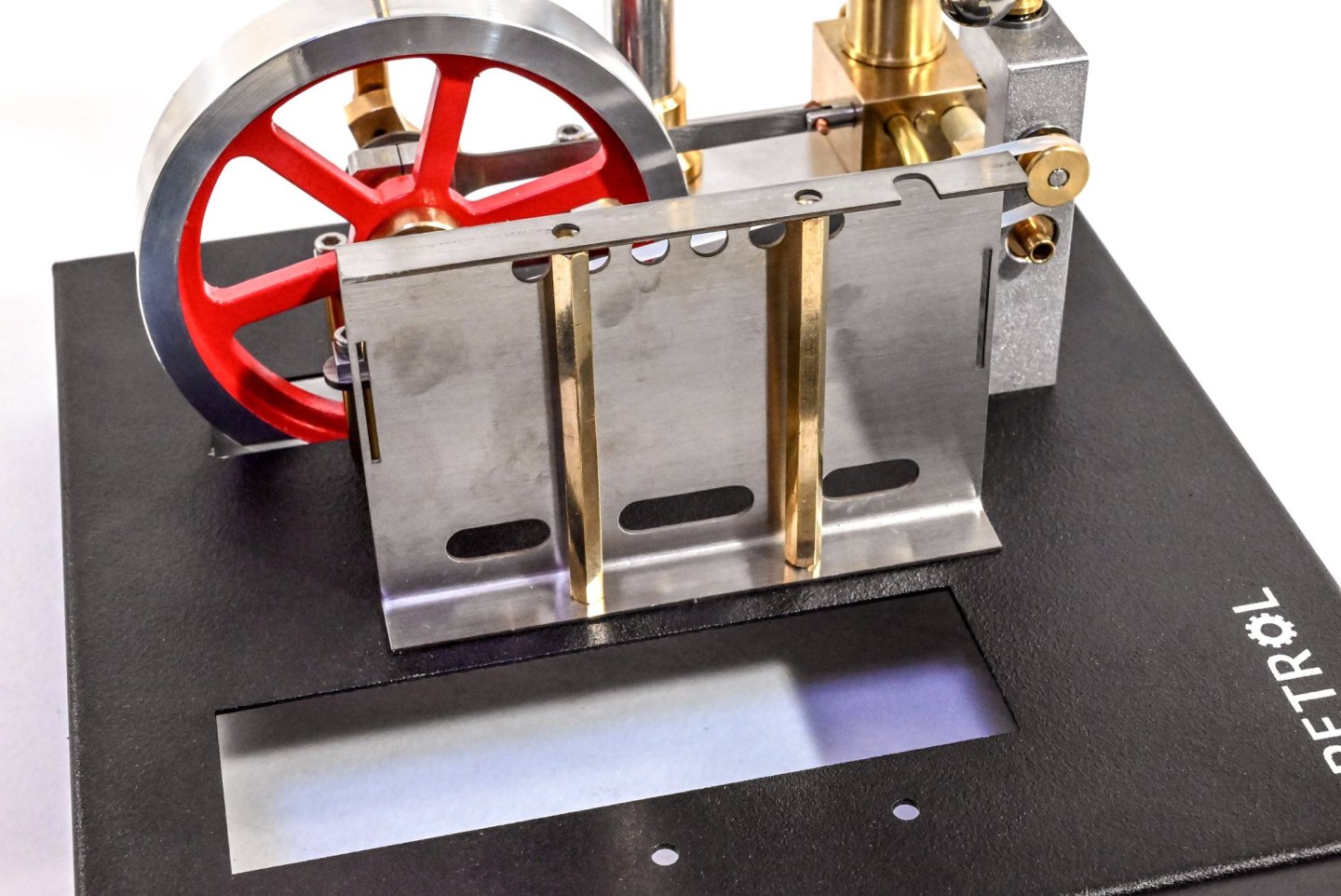
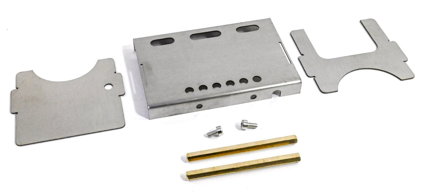
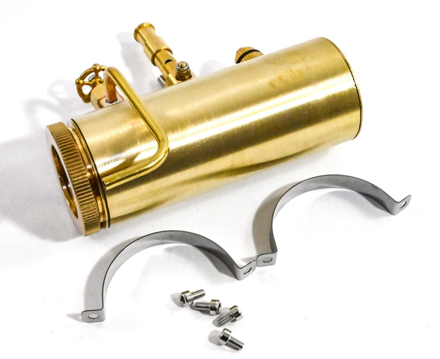
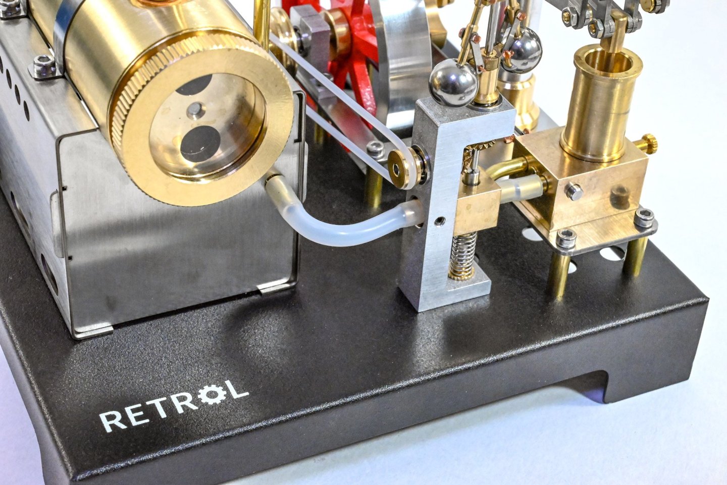
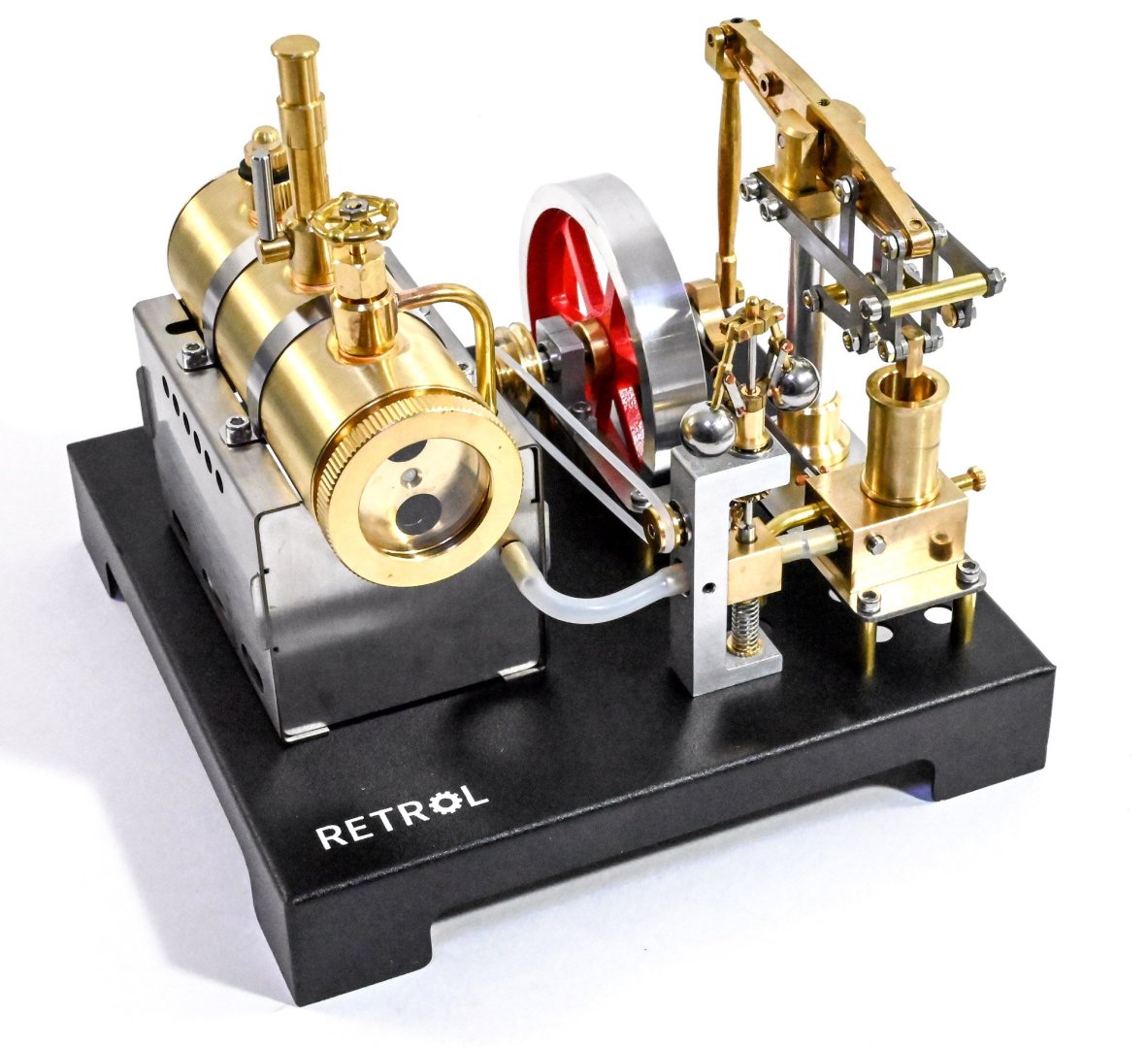
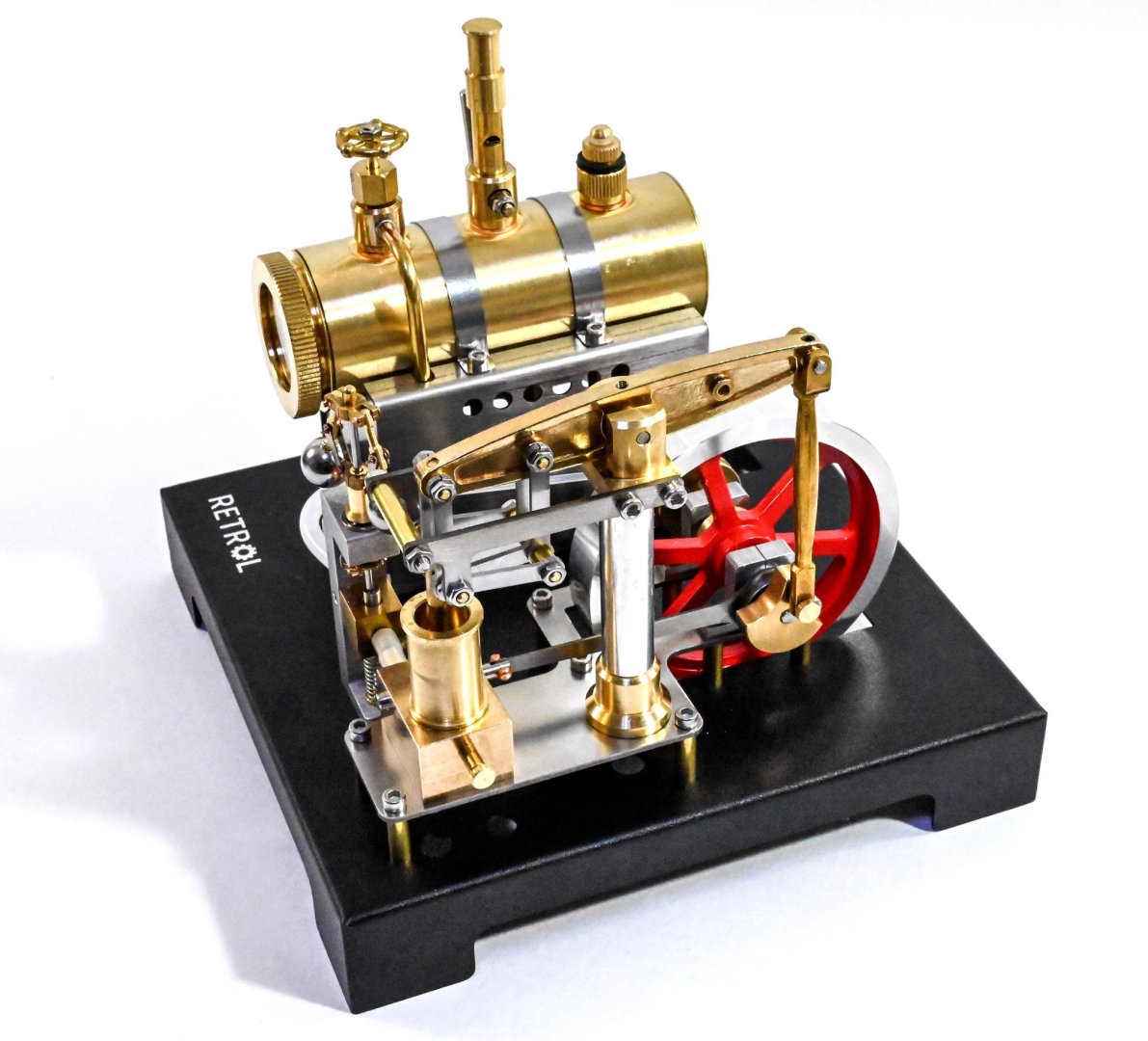
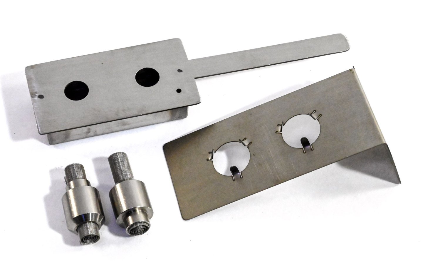
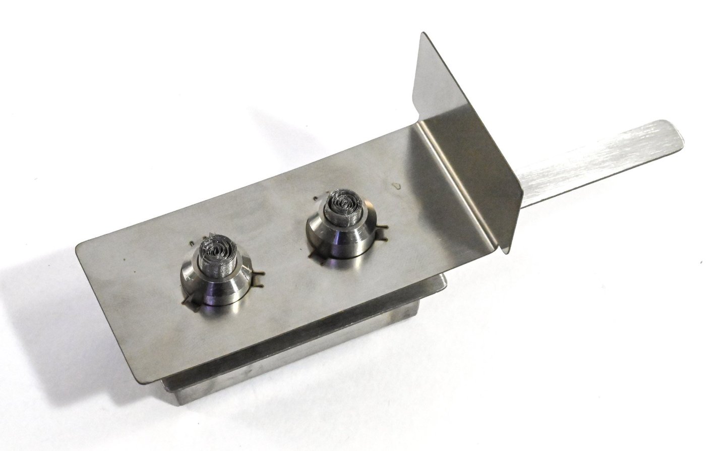
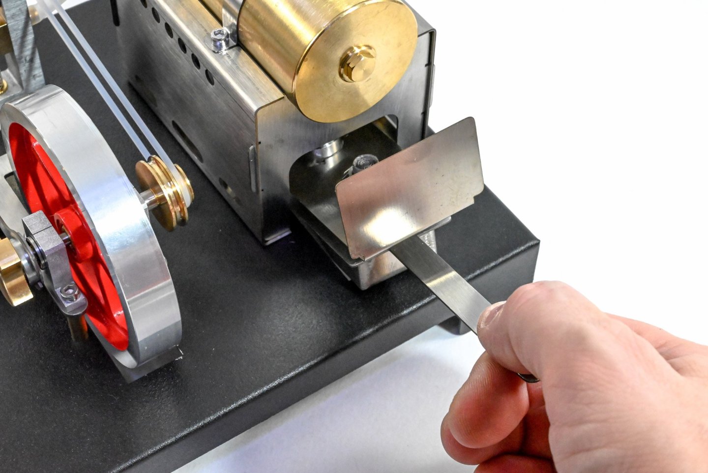
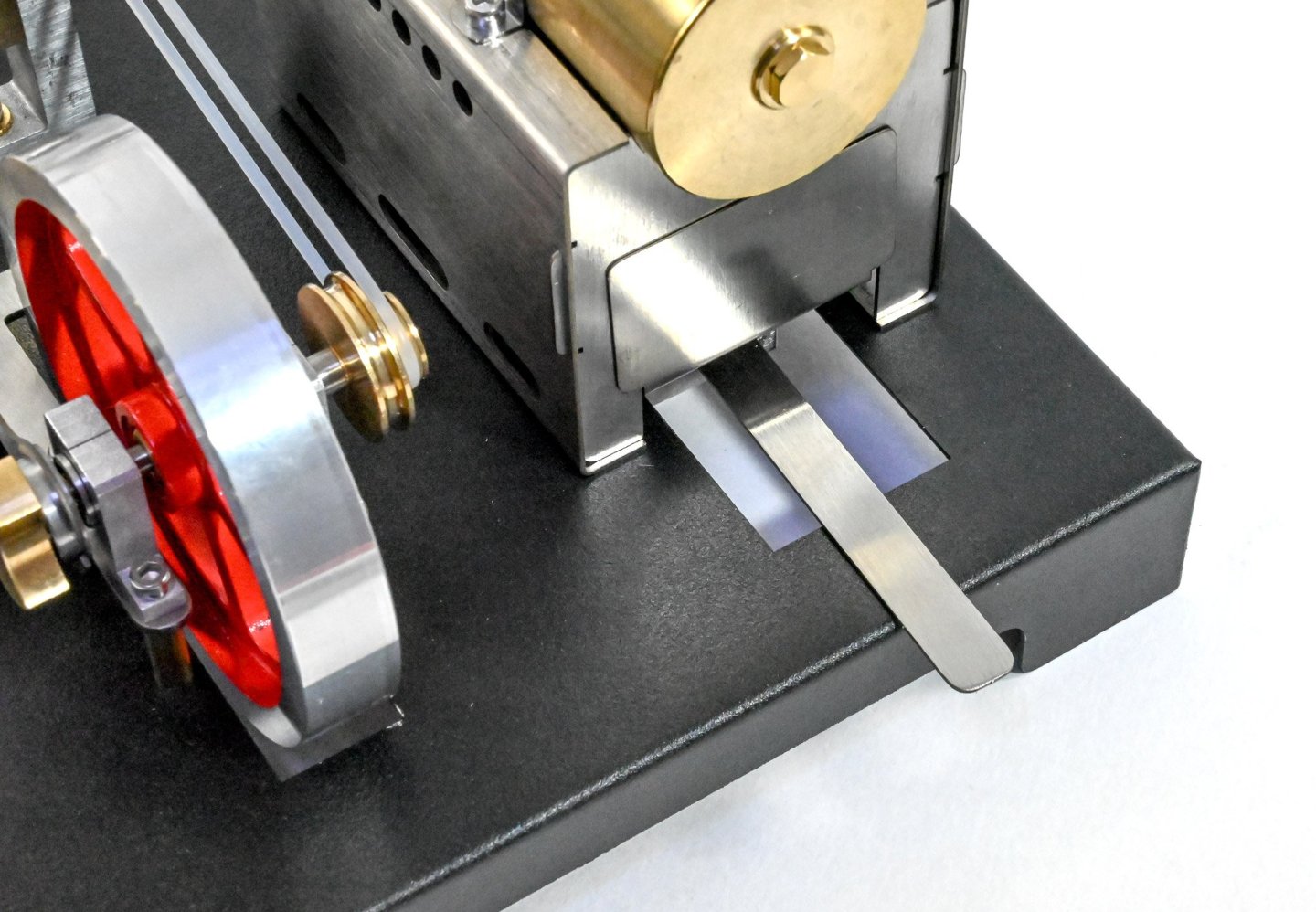
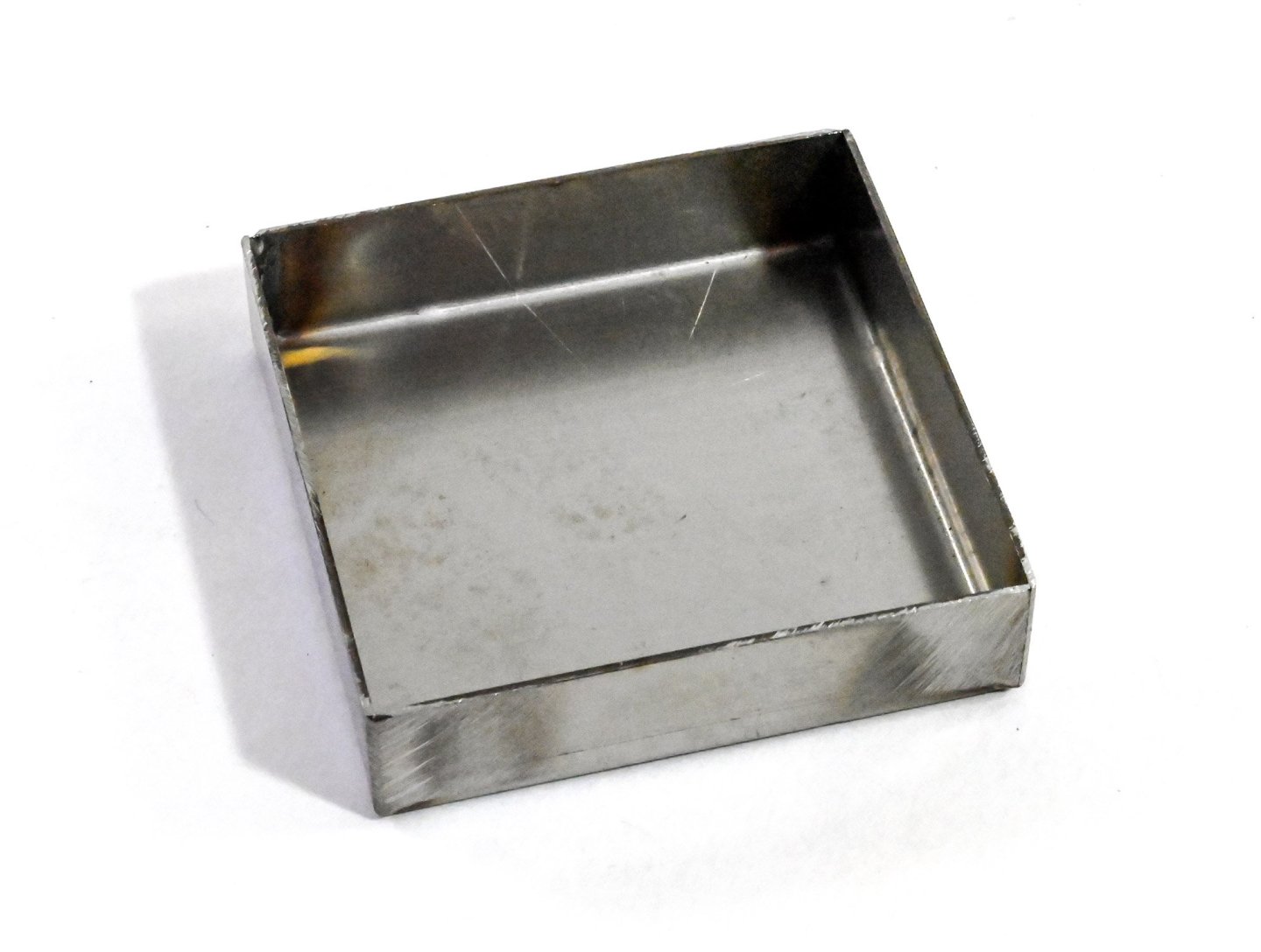
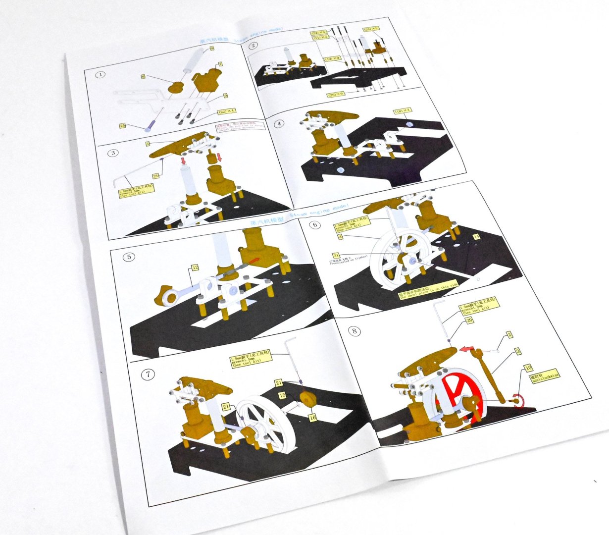
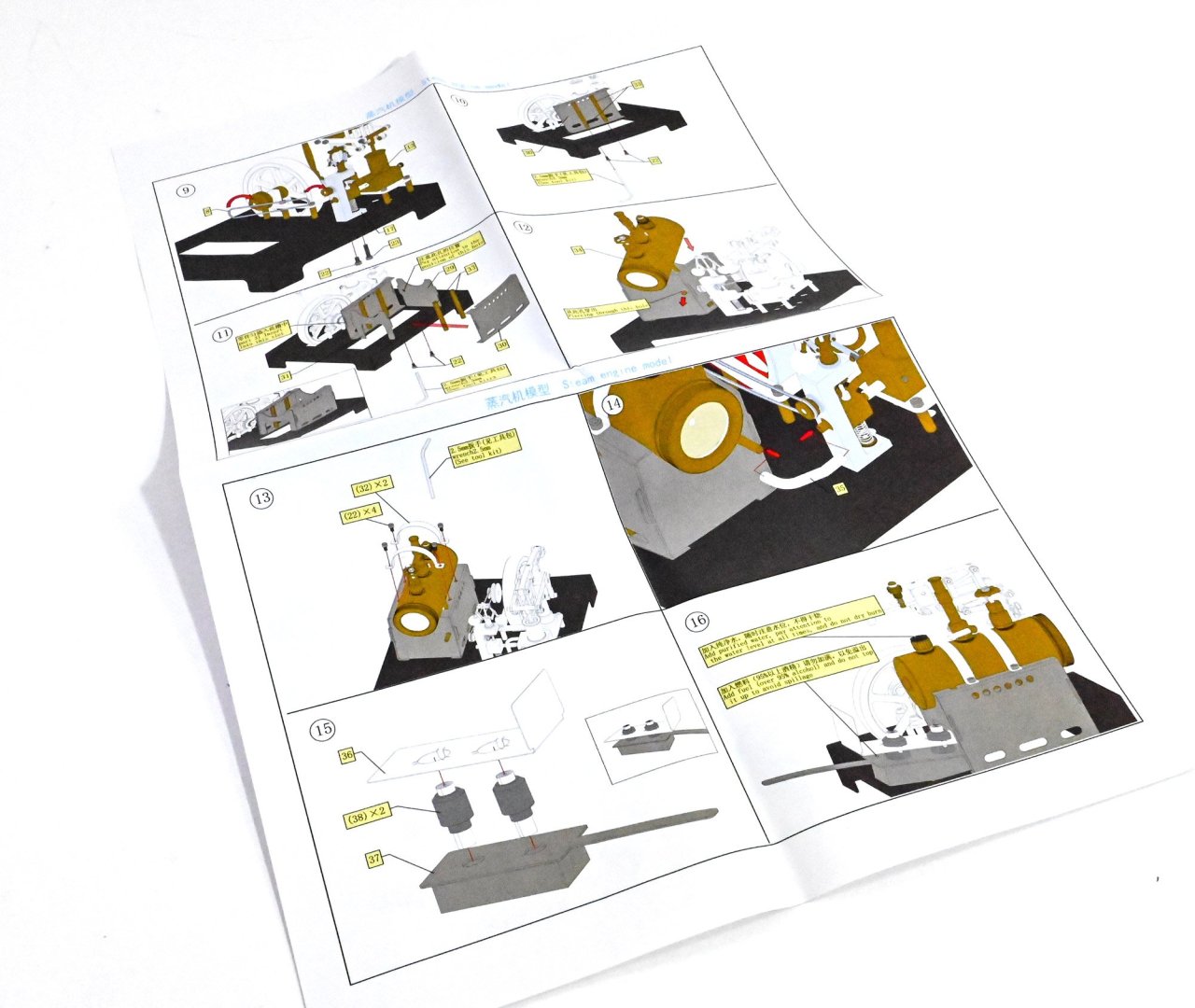
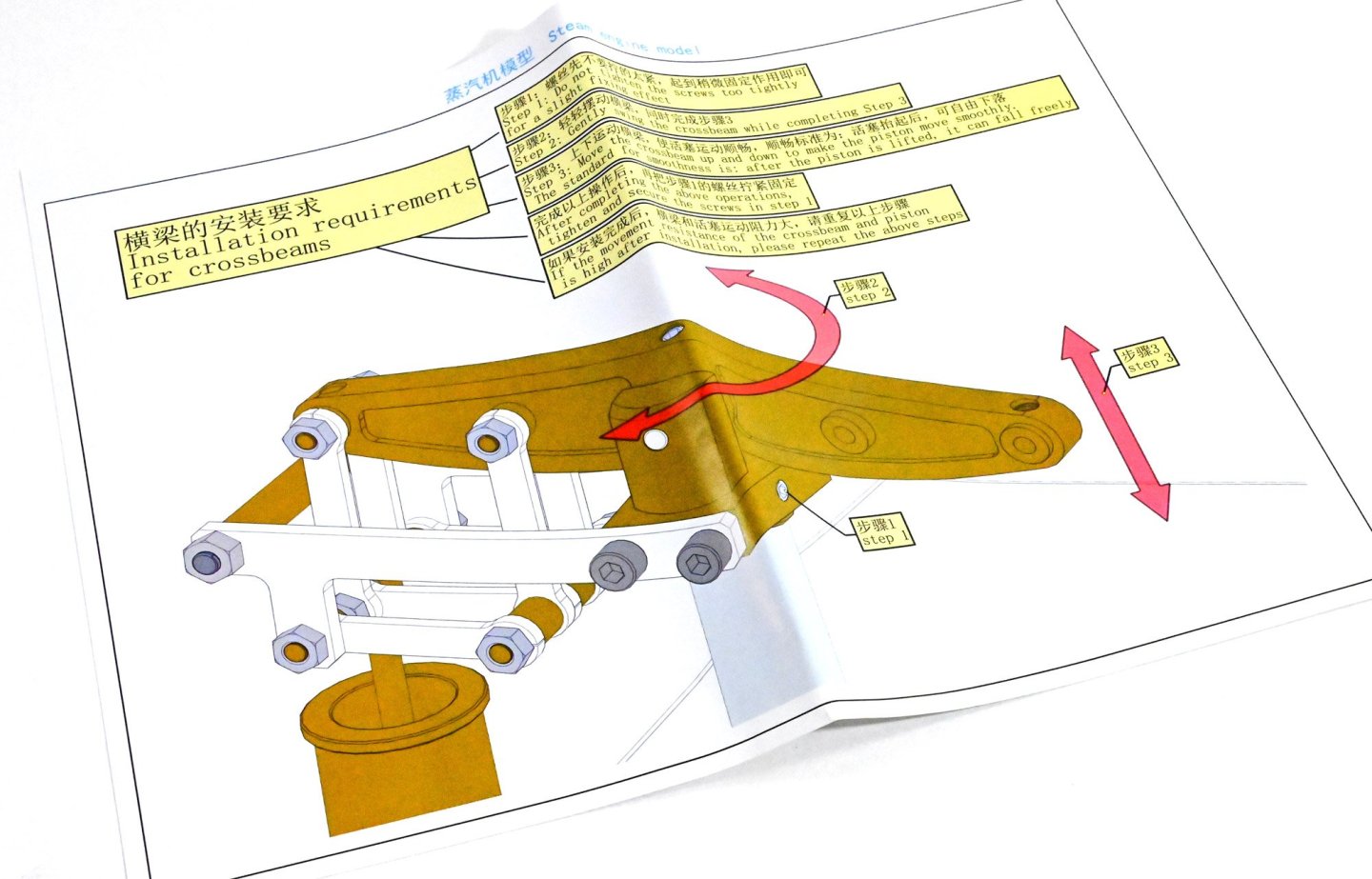
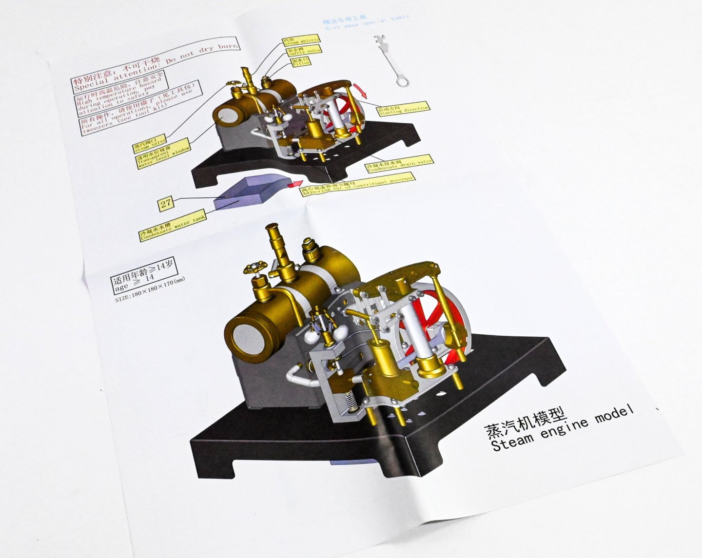
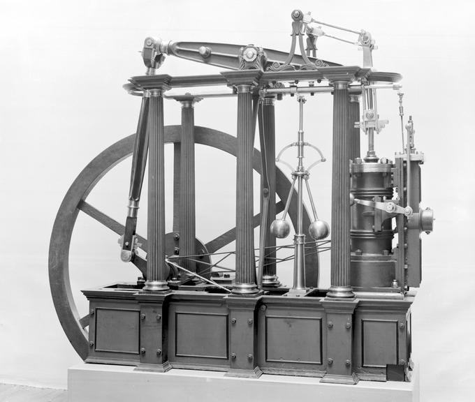
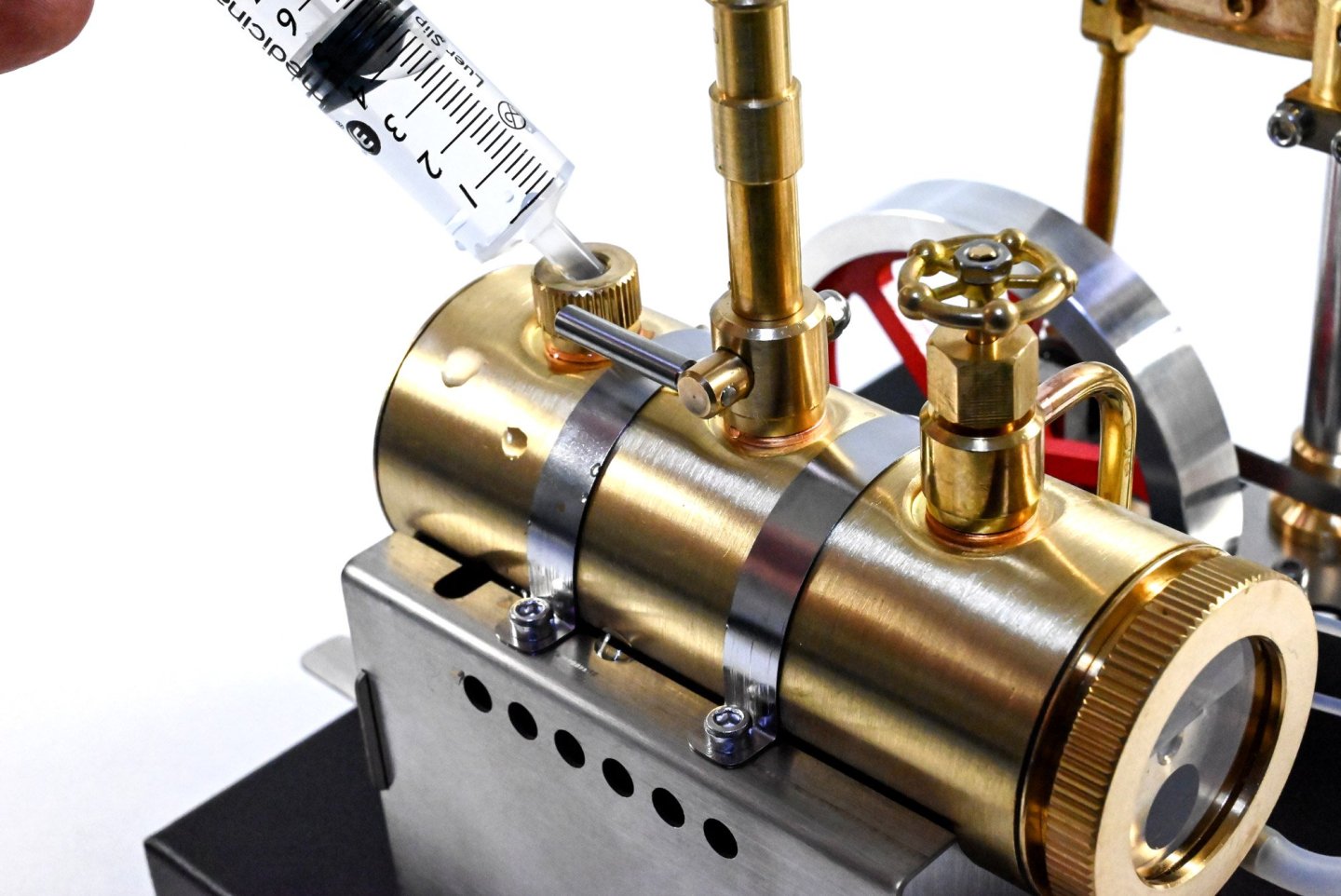
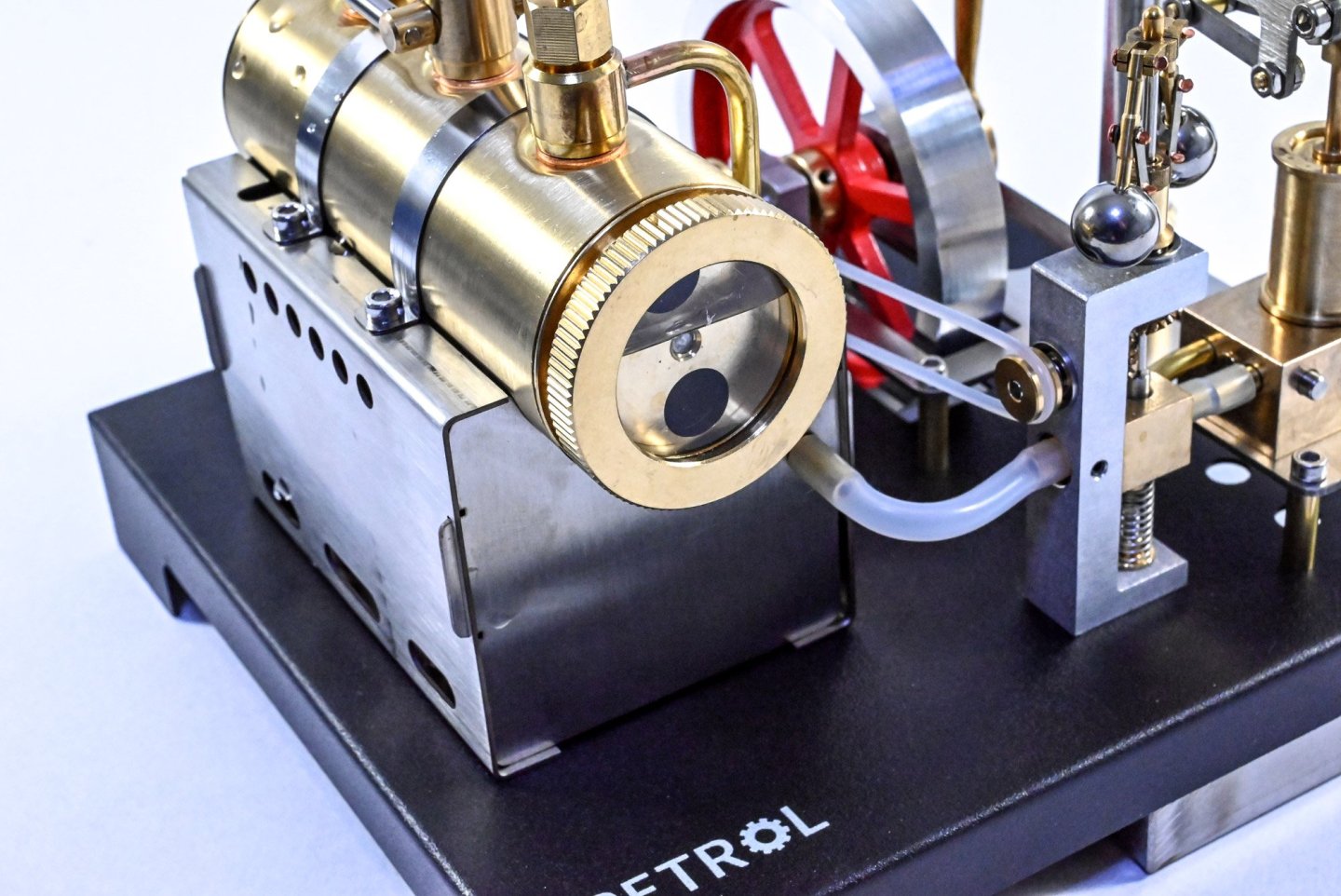
Full Metal Beam Engine Steam Engine (RETROL) EngineDIY Catalogue # 33ED3487709 Available from EngineDIY for USD $299.99 A beam engine is a type of steam engine where a pivoted overhead beam is used to apply the force from a vertical piston to a vertical connecting rod. This configuration, with the engine directly driving a pump, was first used by Thomas Newcomen around 1705 to remove water from mines in Cornwall. The efficiency of the engines was improved by engineers including James Watt, who added a separate condenser; Jonathan Hornblower and Arthur Woolf, who compounded the cylinders; and William McNaught, who devised a method of compounding an existing engine. Beam engines were first used to pump water out of mines or into canals but could be used to pump water to supplement the flow for a waterwheel powering a mill. They also could be used to power steam ships. The first steam-powered ships used variants of the rotative beam engine. These marine steam engines – known as side-lever, grasshopper, crosshead, or 'walking beam', among others – all varied from the original land-based machines by locating the beam or beams in different positions to take up less room on board ship. The kit This steam engine kit comes in quite an anonymous and thick gauge cardboard box with absolutely no label! The box itself is reasonably heavy too, weighing in at just under 2kg. Lifting that lid off immediately shows the colour printed instruction sheets which are sat on a sheet of foam which protects the two trays of parts underneath. This kit contains 84 parts, inclusive of screws etc. All parts are sat in foam cutouts which provide excellent protection for the assemblies and parts. I say assemblies, because I see this as more of a semi-kit in that a number of elements are pre-built, and the idea is to assemble these to the individual parts, which are all then mounted on a metal base. A number of the parts are in plastic sleeves. These are the ones made from stainless steel, and are for building the boiler's mounting chassis, and also the fuel/igniter tray. Work starts on mounting a number of parts to a metal stand-off frame which will eventually mount to the main plinth. This includes the piston mount/condensation block, and the column for the cross beam. Hex keys are provided for the bolts, as well as a spanner with various sized jaws for various nuts etc. This assembly can now be mounted to the main plinth. This is done via a series of brass stand-offs. I'll also now fit the two fly wheel mounts. All screws are tightened up except for those holding the brackets. I decided to make sure I align the drive shaft through them before properly tightening up. This is the cross beam, and one of the number of pre-built assemblies in this model. This is composted of cast and turned brass, plus stainless steel. You can see the piston plunger on the right of the image. This is now fitted to the column using a small grub screw to secure. I ddi apply a little lubricating oil into the piston chamber first and then made sure the beam would move freely, pulling the piston up and down. A separate sheet of instructions gives tips on how to achieve this. If not done correctly, this is about the only area which will cause enough friction to stop the engine from running freely. I found I needed to do a little adjustment of the base of the beam. That's why you can see an adjustment hole underneath this, in the main plinth. The idea is that once the piston is raised, it will drop into the piston cylinder due to gravity. This drive arm is now lubricated and slid into the base of the piston block, and the two bearings are interred into the outside of each of the brackets. Notice the larger end isn't yet engaged into anything and is sat on the bracket simply for the photo opportunity! You could say this is one of the main events...the fly wheel. This beautifully machines piece of aluminium will now be fitted between the two bearings, via that drive shaft. Flats are machined onto this so the grub screws have a proper surface to fasten to. The opposite side of the drive arm is now engaged into the drive shaft and a grub screw used to tighten up to the machined flat on the shaft. The drive wheel can now also be secured to the drive shaft via a grub screw. A small collar is used to help space the components. This is the beam link which will connect the beam to the flywheel drive shaft. The brass fastener has a reverse screw thread which secures into the drive arm. This beautiful little assembly is the centrifugal regulator. The lowest bolt needs to be removed from the unit and reattached from the underside of the plinth, along with the smaller bolt you can see here. Pushing the small brass linkage downwards will force the two balanced wheels outwards. This is what will happen when pressure is pushed through the brass block that you can see midway down the assembly. A small length of silicone tube is used to link the centrifugal regulator to the condensate box/piston chamber. Lastly, for this section, a silicone drive belt is applied between the centrifugal regulator and the fly wheel. The boiler sits atop a stainless housing which doubles as the heat box for the boiler. The first side is fitted, via two brass shafts which also help reinforce the assembly, as well as create mounting points for the boiler securing straps. The box is now complete, with the scalloped side towards the top, and the square cutout as shown. The latter is to accommodate the fuel tray. This really is a very nice piece of engineering, mostly from machined brass. I remember the boilers from the Mamod steam engines, and I can vouch that there are flimsier than this, and that had soldered joints. This is a far superior unit. The boiler is now fitted and secured. The protruding outlet pipe is connected to the centrifugal regulator via a length of silicone tubing. The steam engine itself is now complete. These parts assemble to create the fuel tray. This contains a tray into which the fuel (methylated spirits, IDA etc) will be poured. The 'wick' units which create a chamber from where the fuel vapours emit, are then plugged into the tray and then the cap is fitted. This creates a shield which closes off the fuel chamber from the outside world. The underside of the piston block has that condensation pipe. This little tray will sit underneath that whilst in operation. Instructions These are quite sparse in text, with quite a lot of Chinese present, but the illustrations themselves are enough to easily build this steam engine. With the engine complete, we can now give it a test. First, the safety valve needs to be unscrewed and then water added. I do this with a syringe. First you need to open the valve at the front of the boiler, or the water will just leak from the injection point, as you add it. I found that about 60ml of water was enough for this. I also added about 10ml to 12ml of methylated spirits to the fuel tray and then lit the burner. The boiler took just a few minutes to come to pressure. The flywheel began to rotate slowly, so I gave it a gentle push and off it went! Conclusion Firstly, I have to say that this is a delightful little steam engine that is both easy to understand and build. This took me a little over 90 minutes to build, inclusive of taking the unedited photos. The quality of parts really is excellent, which is what you need when you are dabbling with a miniature boiler unit and the pressures within. The overall feel of the kit and the finished model is one of quality. All I would suggest is adding a little lube in areas such as the piston and gearing in the centrifugal regulator etc. When you compare the beautiful finished model here, compared with the current Mamod models which are pre-built and cost over a £100 more than this, then I consider this to be excellent value for money. It will also make a wonderful cabinet display piece too, which is exactly where mine will be heading. My sincere thanks to EngineDIY for sending out this kit for review on Model Ship World. To buy direct, click the link in the header of this topic.


-
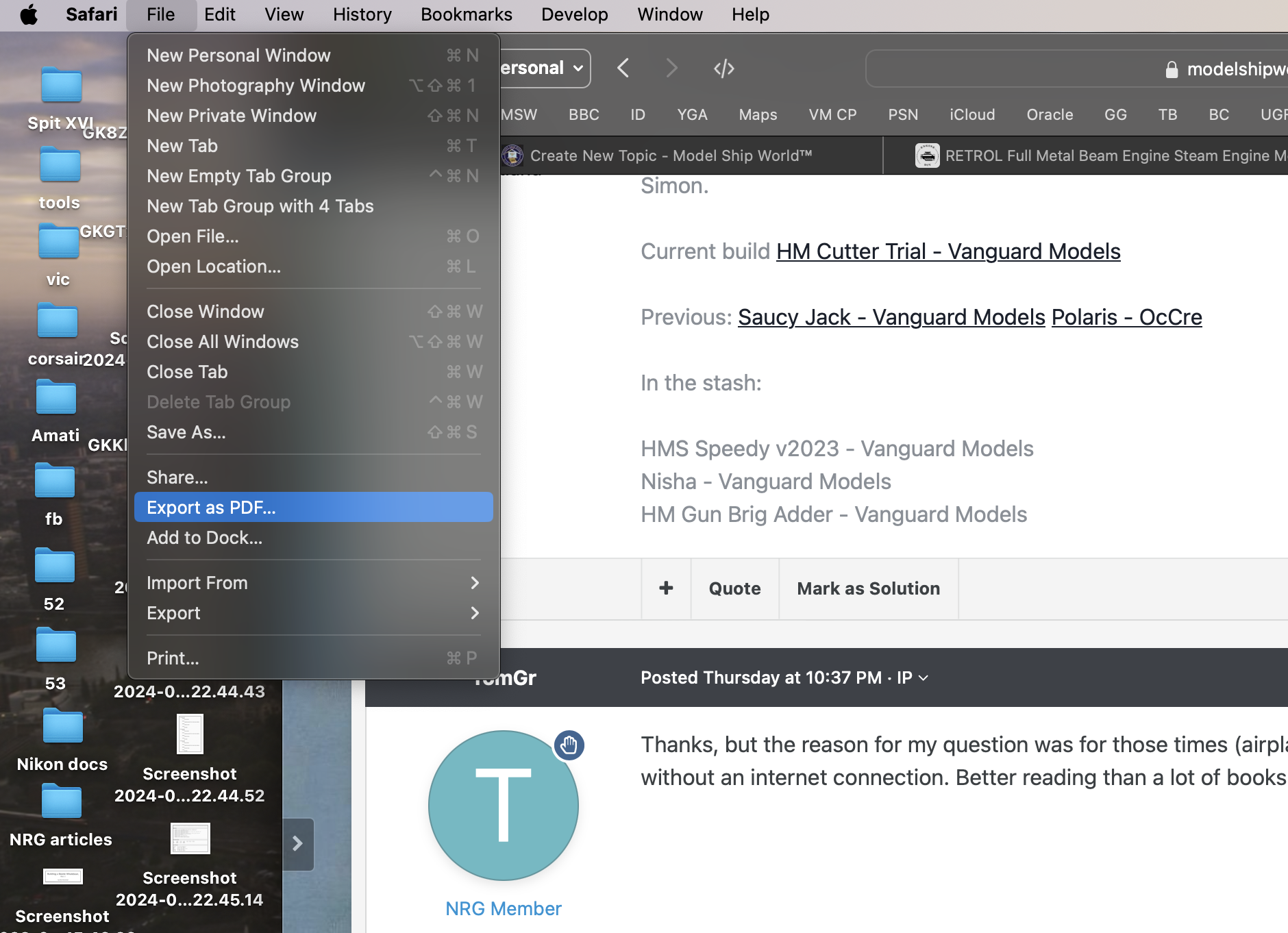
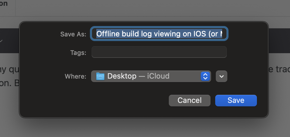
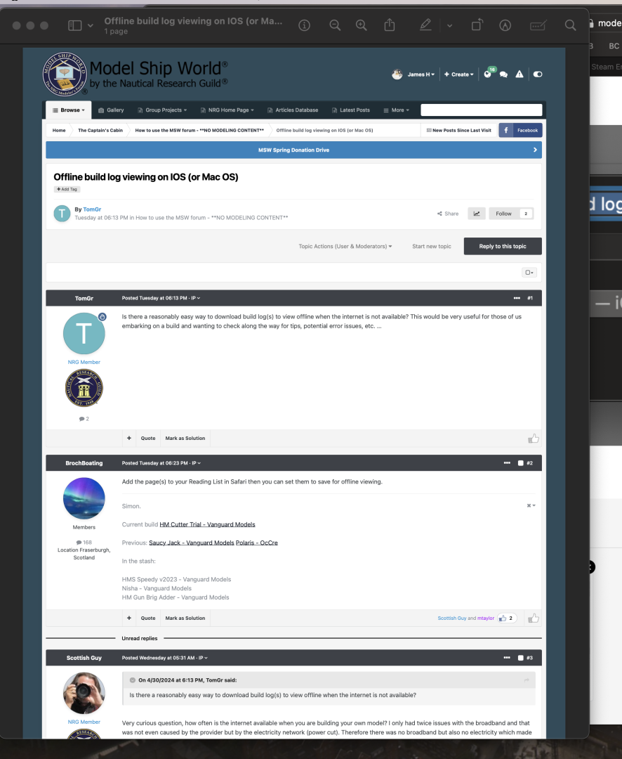
Well, I'm on Mac Safari, and I can do this. No special plugins or software necessary:


-
Kit review 1:80 Rainbow – America’s Cup 1934 - Amati
James H replied to James H's topic in REVIEWS: Model kits
I totally agree! -
kit review 5 Cylinder Radial Engine (TECHING) - EngineDIY
James H replied to James H's topic in Non ship-related reviews
I’m told that it’s a 16% code, if anyone wants it. -
kit review 5 Cylinder Radial Engine (TECHING) - EngineDIY
James H replied to James H's topic in Non ship-related reviews
If anyone would like a code for a nice 10% discount, drop me a PM and I’ll let you have it. -
Beautiful work, Tom. That's real clean and great to look at 🤗
-
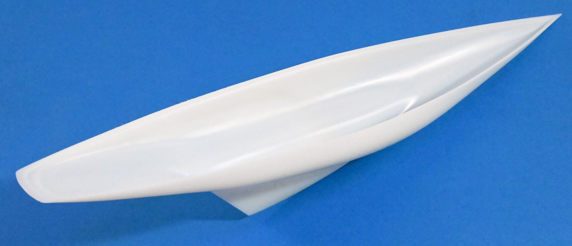
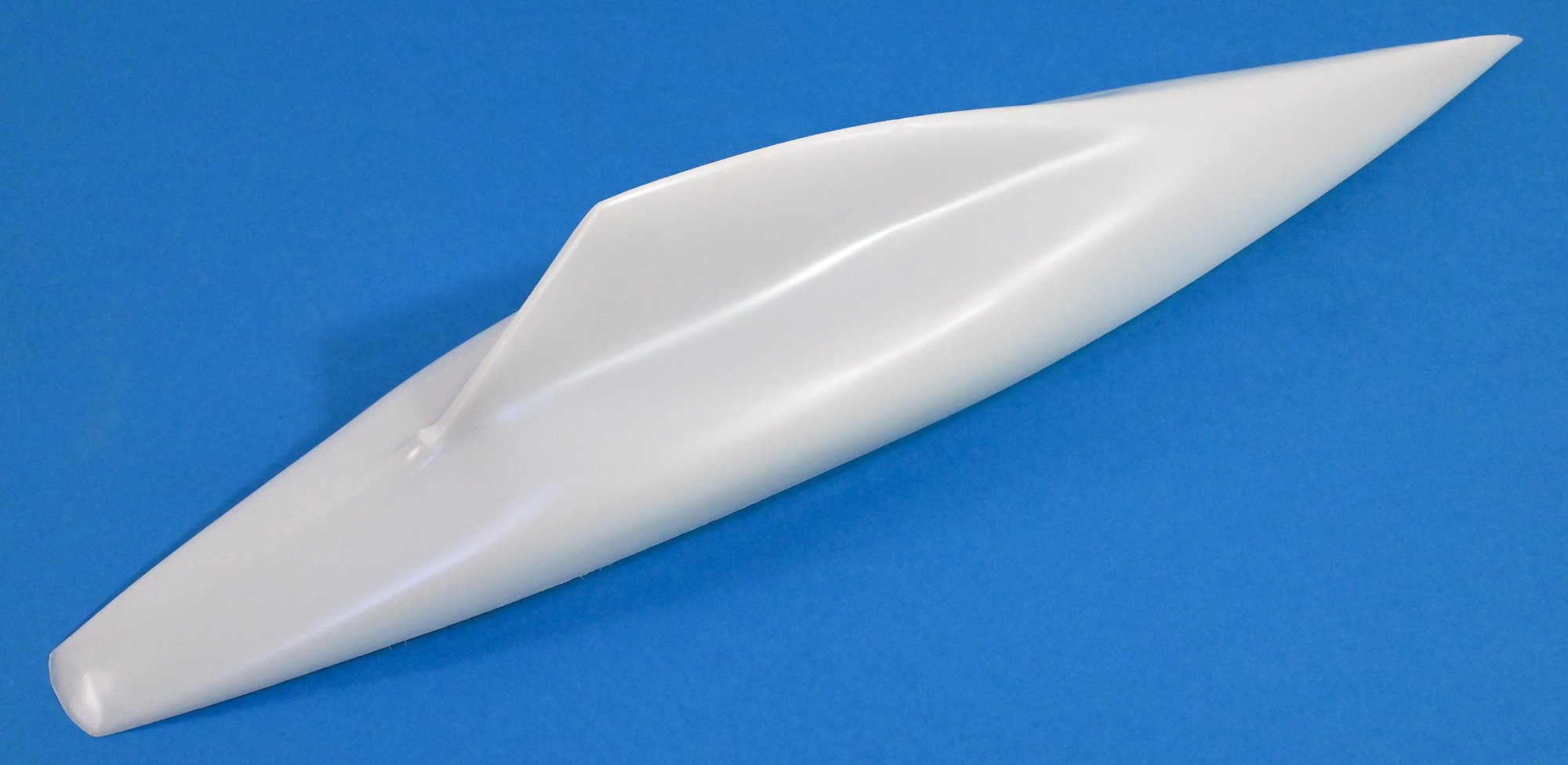
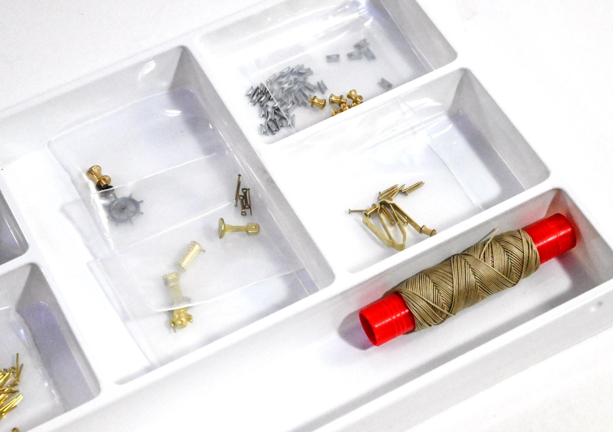
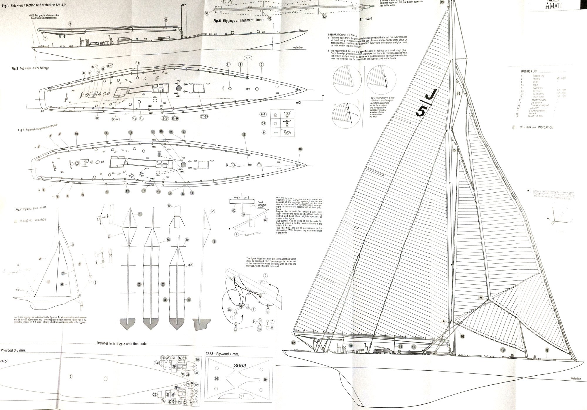
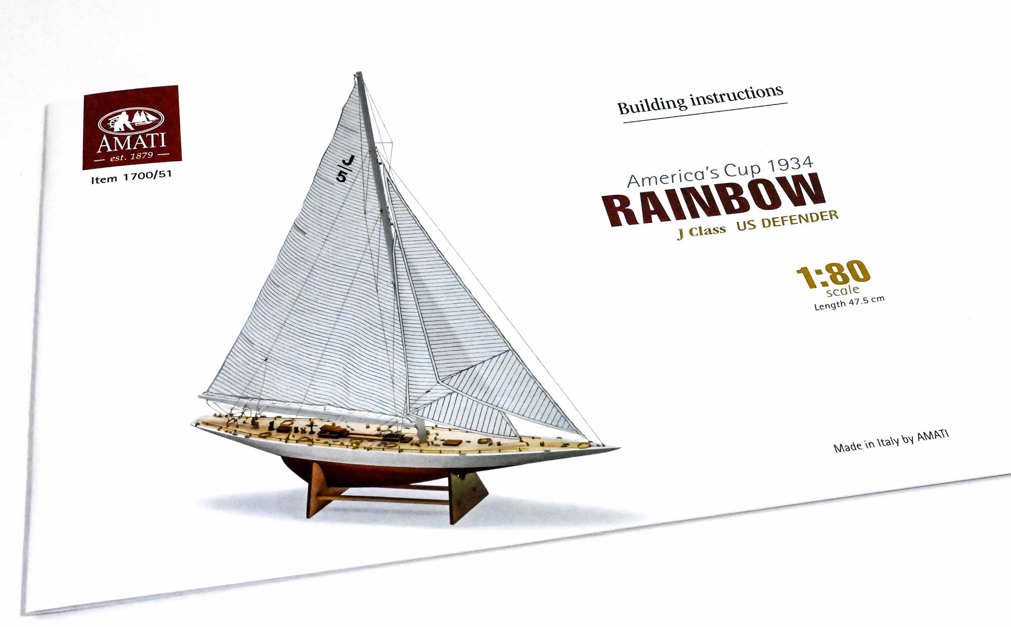
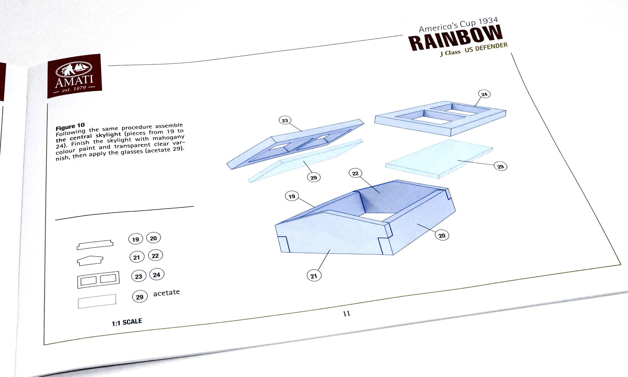
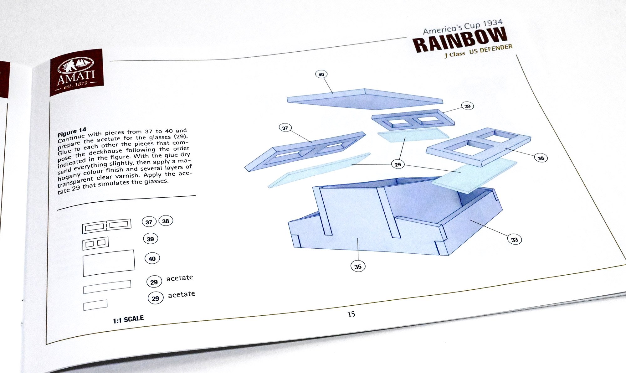
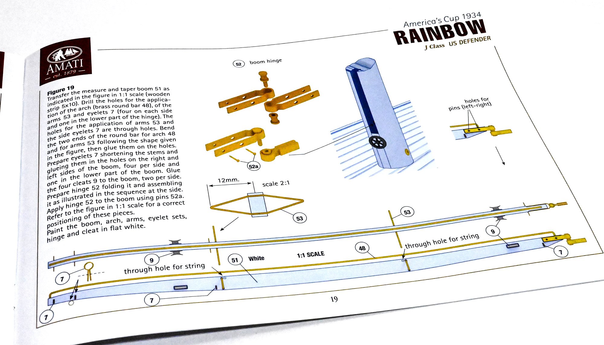
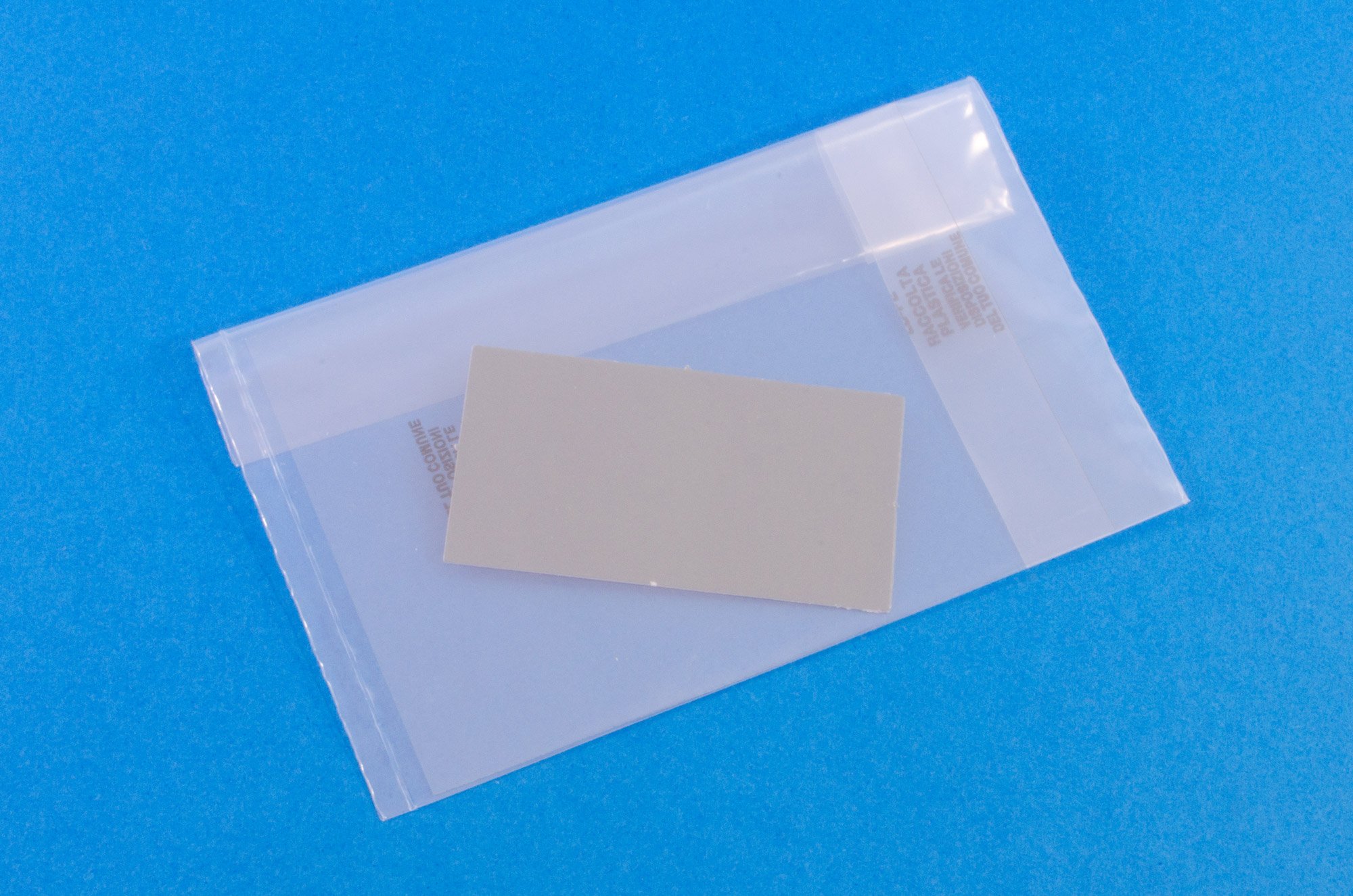
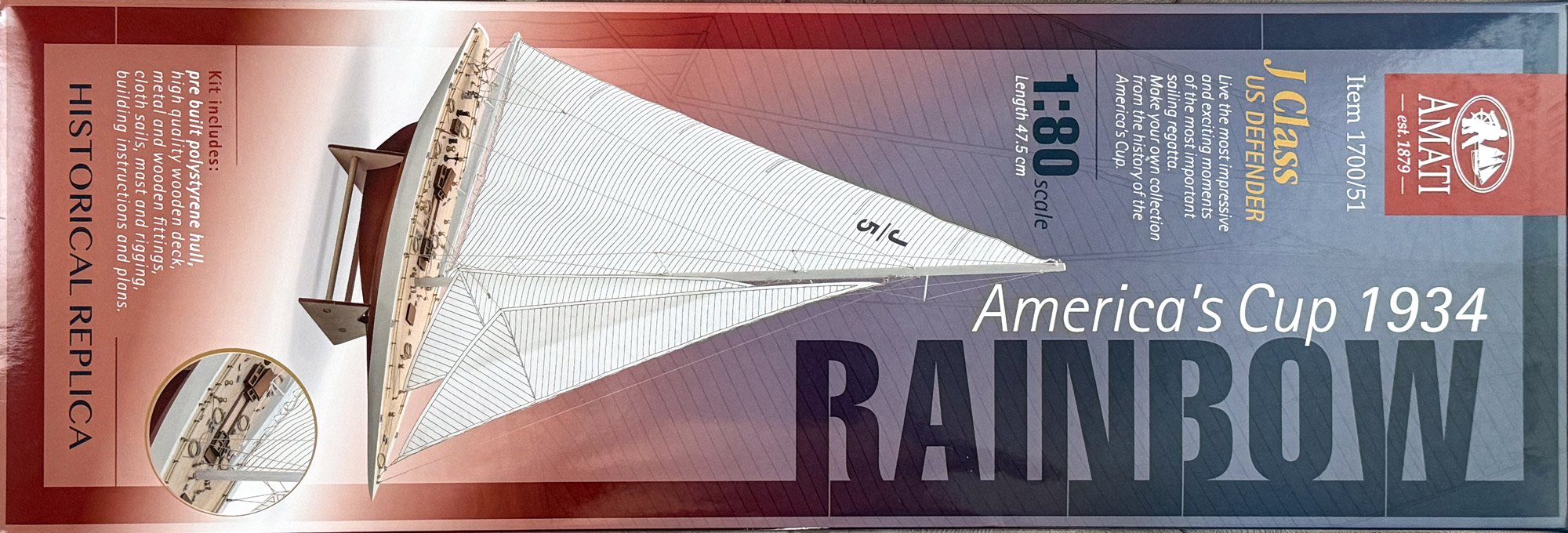
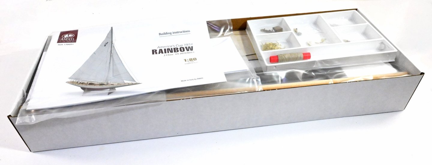
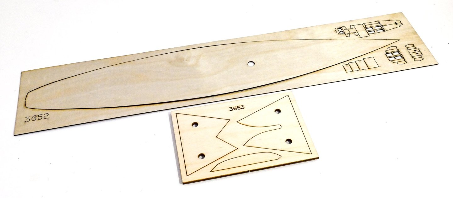
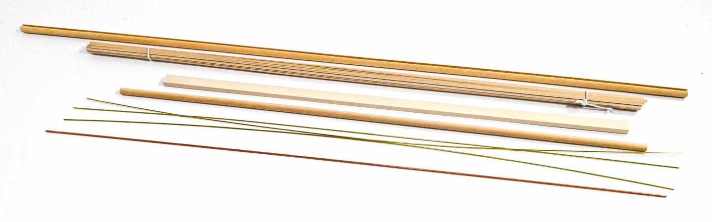
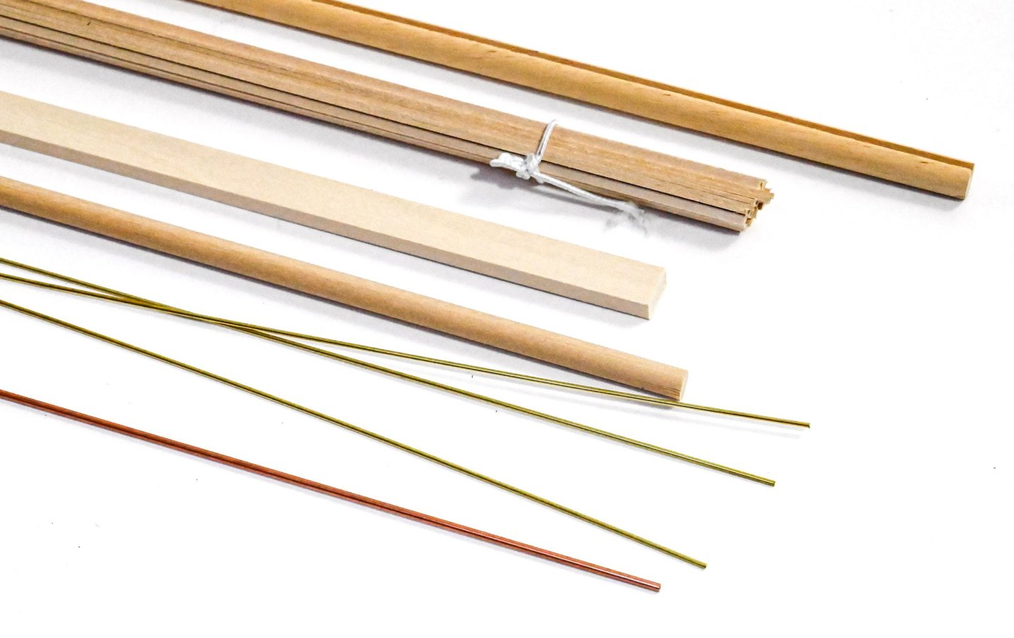
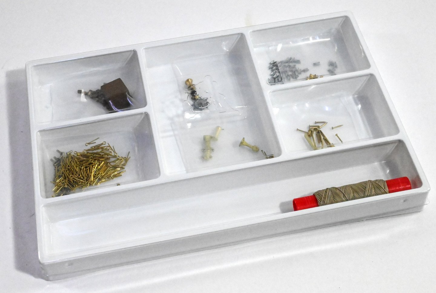
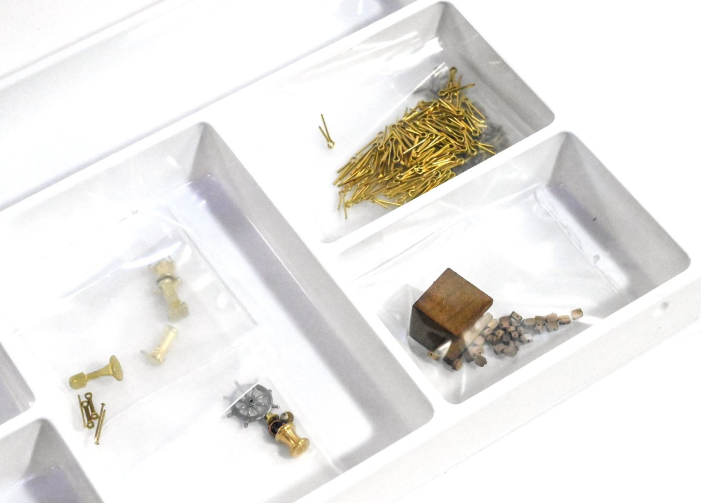
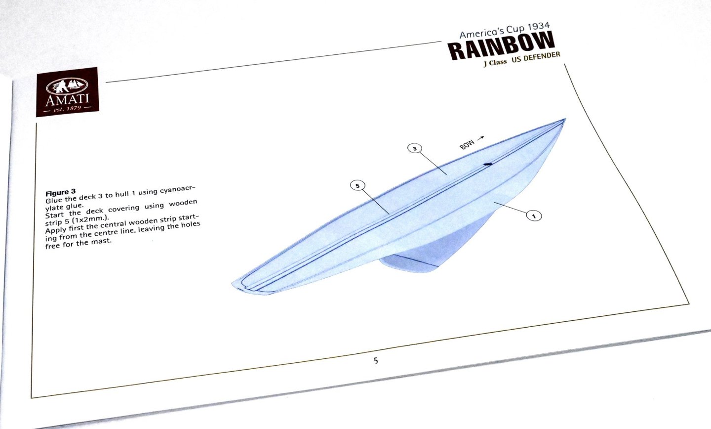
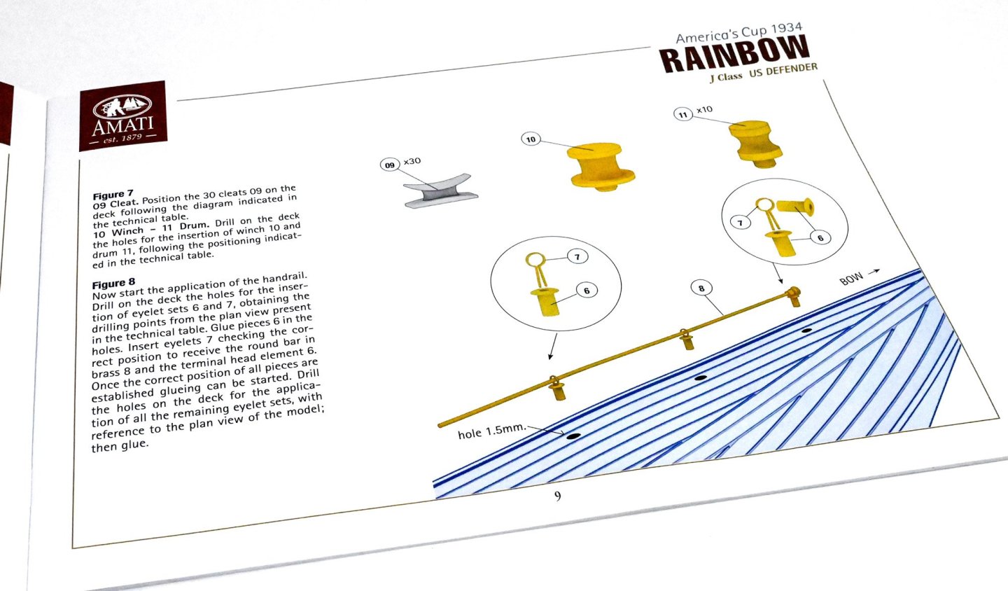
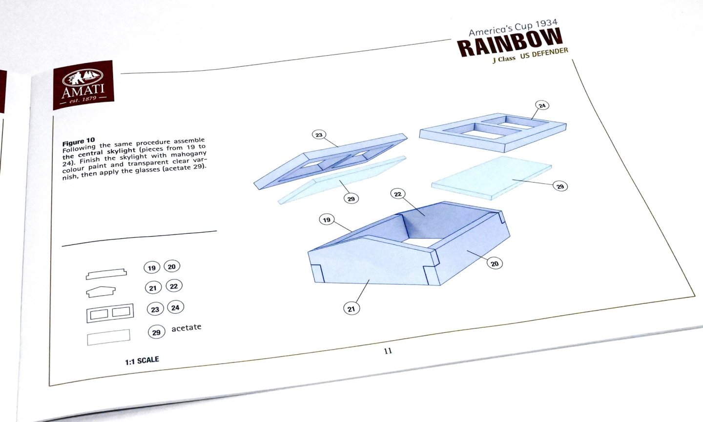
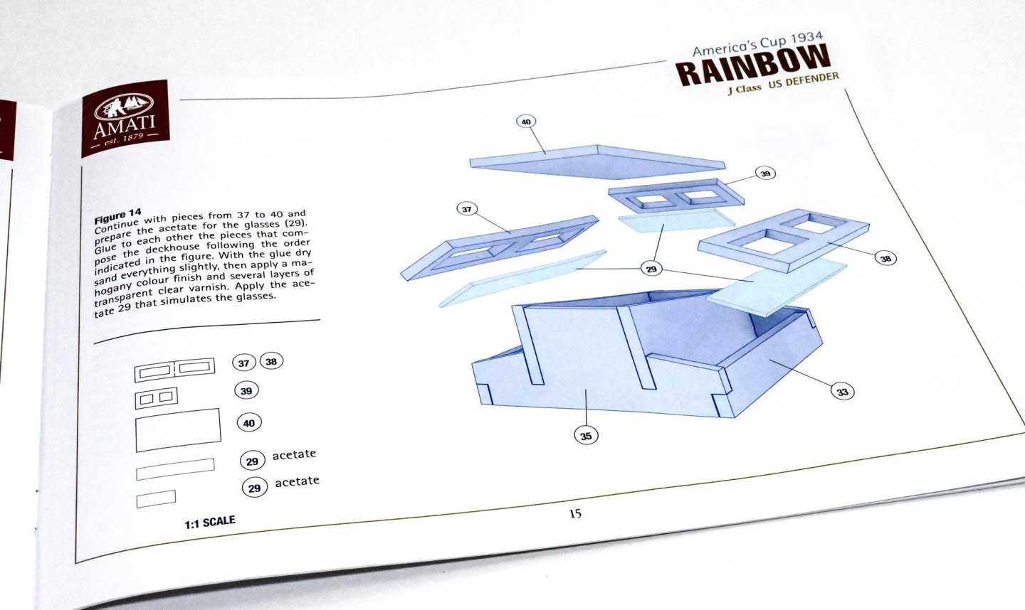
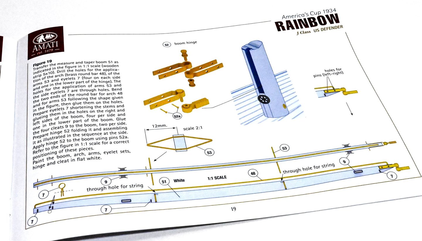
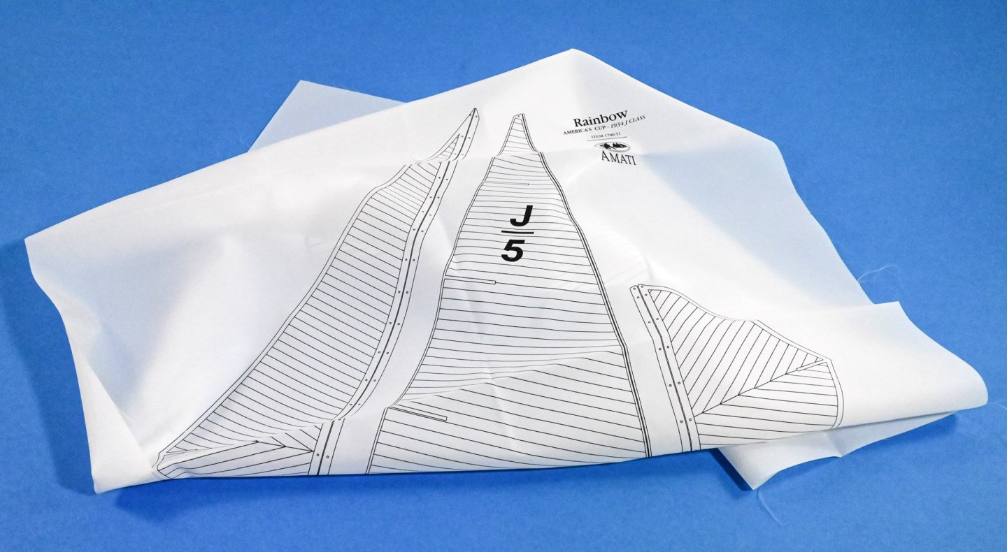
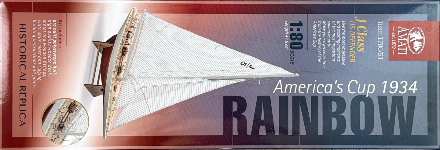
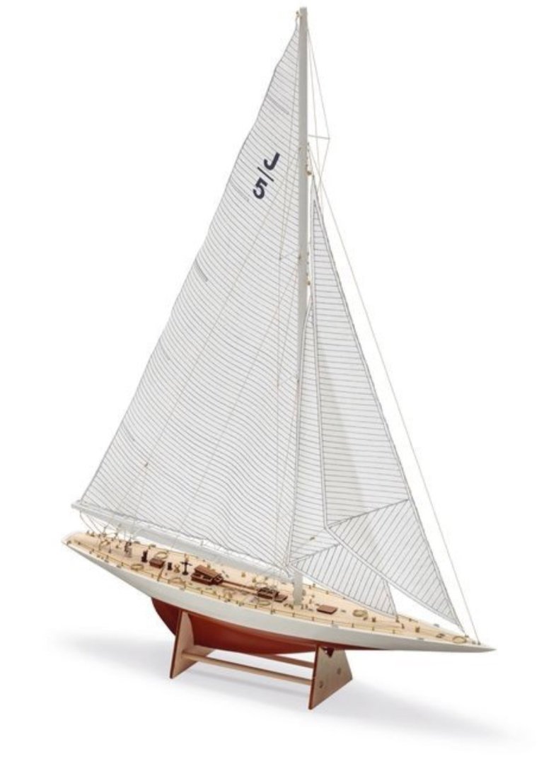
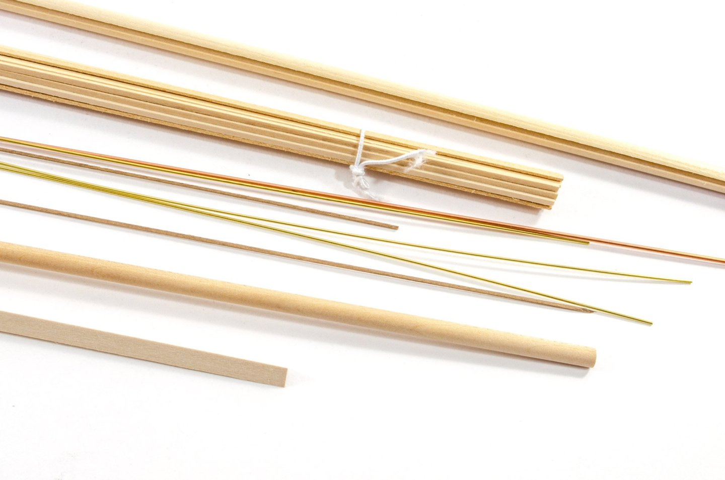
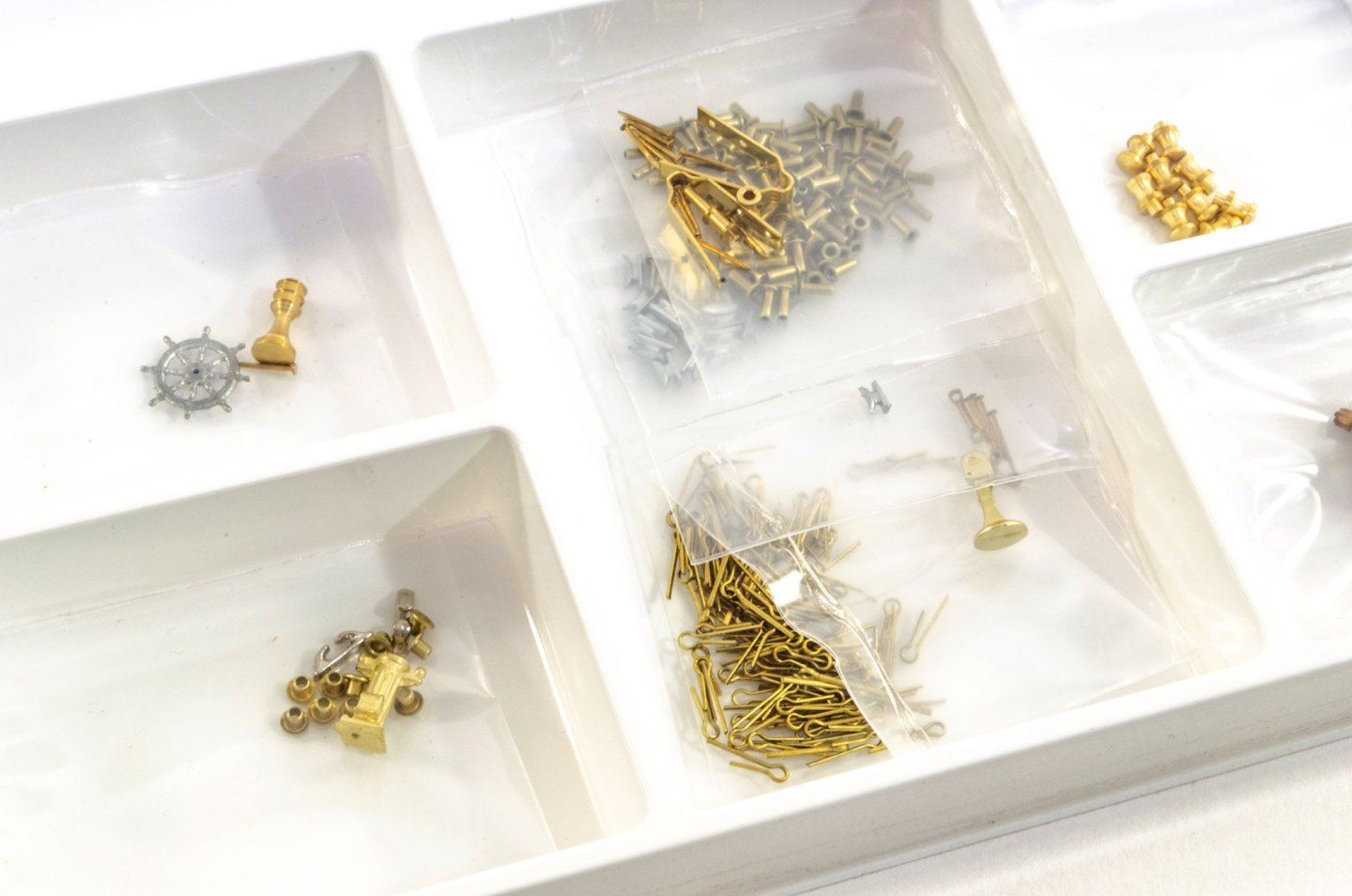
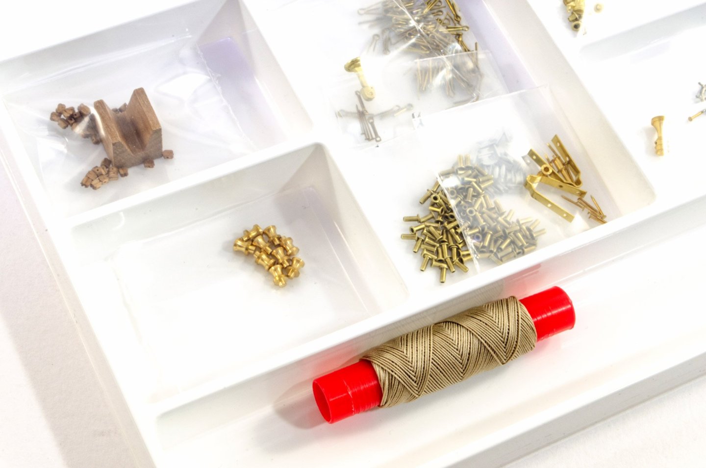
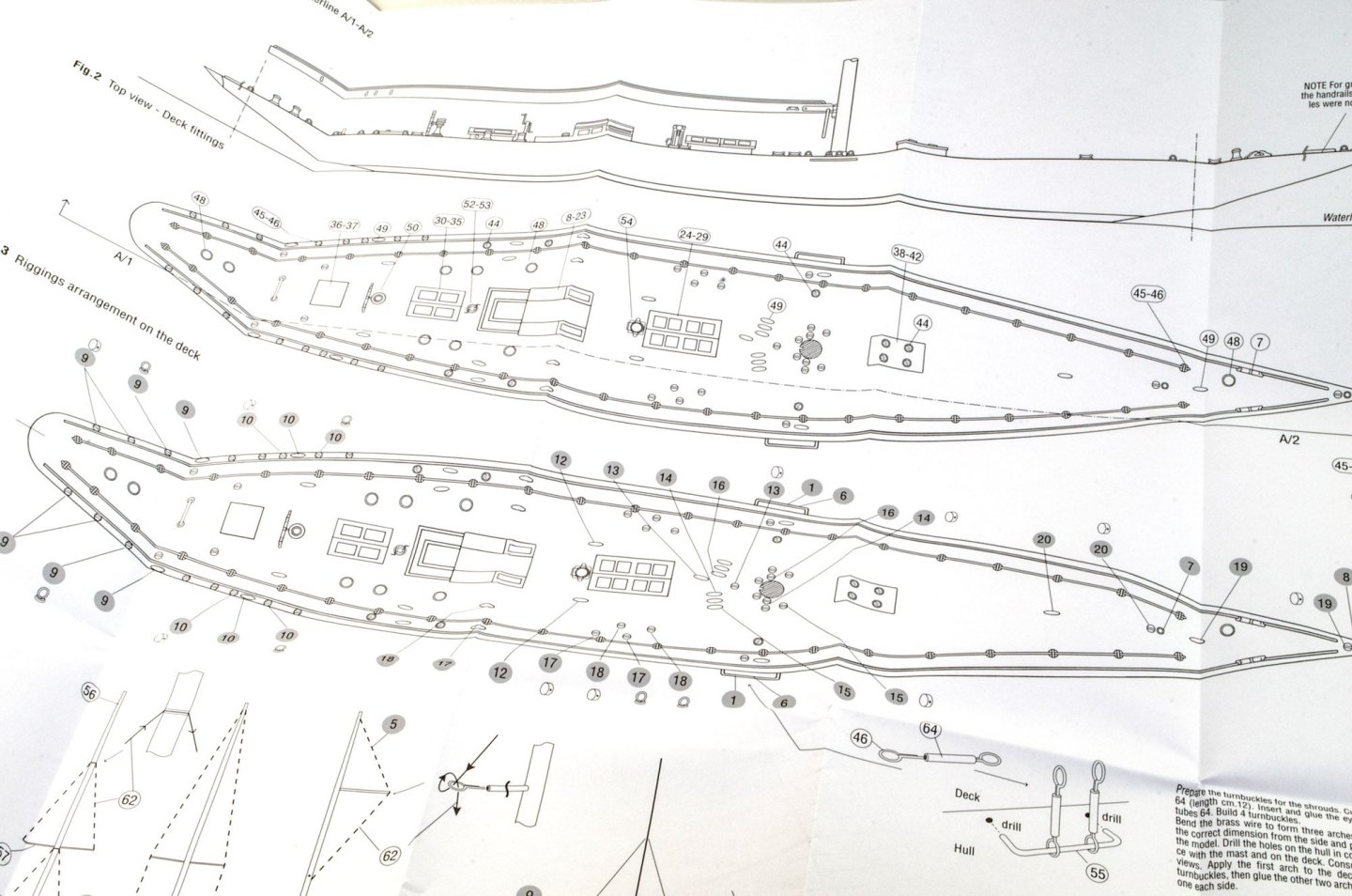
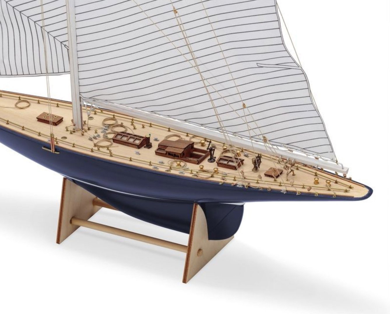
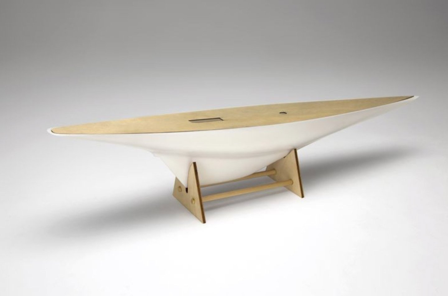
1:80 Rainbow – America’s Cup 1934 Amati Catalogue # 1700/51 Available from Amati for €78,69 History Rainbow was a J-class yacht built in 1930, and successful defender of the 1934 America's Cup. It was ordered by Harold Vanderbilt and designed by William Starling Burgess. Rainbow was scrapped in 1940. (from Wikipedia) The kit Amati’s Rainbow kit is packed into a sturdy and glossy lid-opening box with a photo of the completed model on the front, plus an important dimension stating that the model has a length of 49.5cm. Curiously, for a tall yacht, the height isn’t given. For your info, the model height (taken from the plan sheet) is approx. 67cm tall and 8.8cm wide. This model is also supposed to be suitable for RC. Under the lid, all of the components are elevated by the packing that holds the single-piece, white styrene hull. The moulding of this looks nigh on perfect with a totally smooth finish. No internals are provided for this if you wish to go RC. You’ll need to fathom motor and shaft mounts yourself. For most of us, that doesn’t matter. The rudder is a separate wooden part. The hull is well packed so that it can’t move about whilst in the box. Two sheets of ply are included. These are actually the only timber sheets in the whole kit! The main sheet contains the single-piece deck with superstructure and mast openings. This will need to be planked. There are straight planks which run centrally, but then you need to begin the next phase of planking from the outside edges, working towards the centre. The beauty of this deck will be in the fitting out. On this sheet, there are other parts which are used to build up the various superstructures such as the central and stern skylights. The second, smaller sheet contains the fore and aft display stand parts and also the yacht’s rudder which needs to be shaped. This yacht will need some glazing and this clear sheet is provided for this purpose. There is a nice bundle of strip material in this kit, from the slotted/milled mast, though to deck planking etc. A small quantity of brass and copper is also included. I have to say the timber quality is excellent and very nicely milled/cut. A single tray of fittings is included, with everything packed into bags within. This includes cleats, portholes, eyelets, drums, winch and arm, wheel, binnacle and rigging cord etc. Fittings quality is up to Amati’s usual high standard. One plan sheet is included with the main drawings at 1:1. Whilst the instruction booklet deals with all things to general construction, plus some other elements such as rudder wheel etc, the plan is what you need to refer to for fittings placements, masting and adding sails and rig. White sail material is included. This has all of the yacht’s sails printed on it. You will need to carefully cut these from the sheet and then finished before fitting. A colour manual is included. This covers all the main stages of construction, and some of those which are best illustrated in 3D instead of in plan form. All illustrations are very clear, with the specific parts shown in plan form, adjacent to the 3D illustrations, complete with part numbers. These numbers can be referenced from the plan sheet. Conclusion If you like graceful hull lines, but hate planking, this is for you. Even if you need a quick but satisfying ‘between projects’ build, then this could hit the mark. There aren’t too many parts to this build, by both nature of kit design and also due to the vessel herself. Once you’ve planked that ply deck and fitted to the hull, it’s very much a fitting out project. The quality of the plastic hull is excellent, and you’ve got a real nice base onto which you can then add paint. No plank lines to fill and rub back endless times. She’ll look great in a custom-made acrylic case too, and the kit itself is very reasonably priced. My since thanks to Amati for sending out this kit for us to look at on Model Ship World. Check your local dealer for availability. If unable to purchase via dealer, dead onto Amati to buy directly, via the link at the top of the article.


-
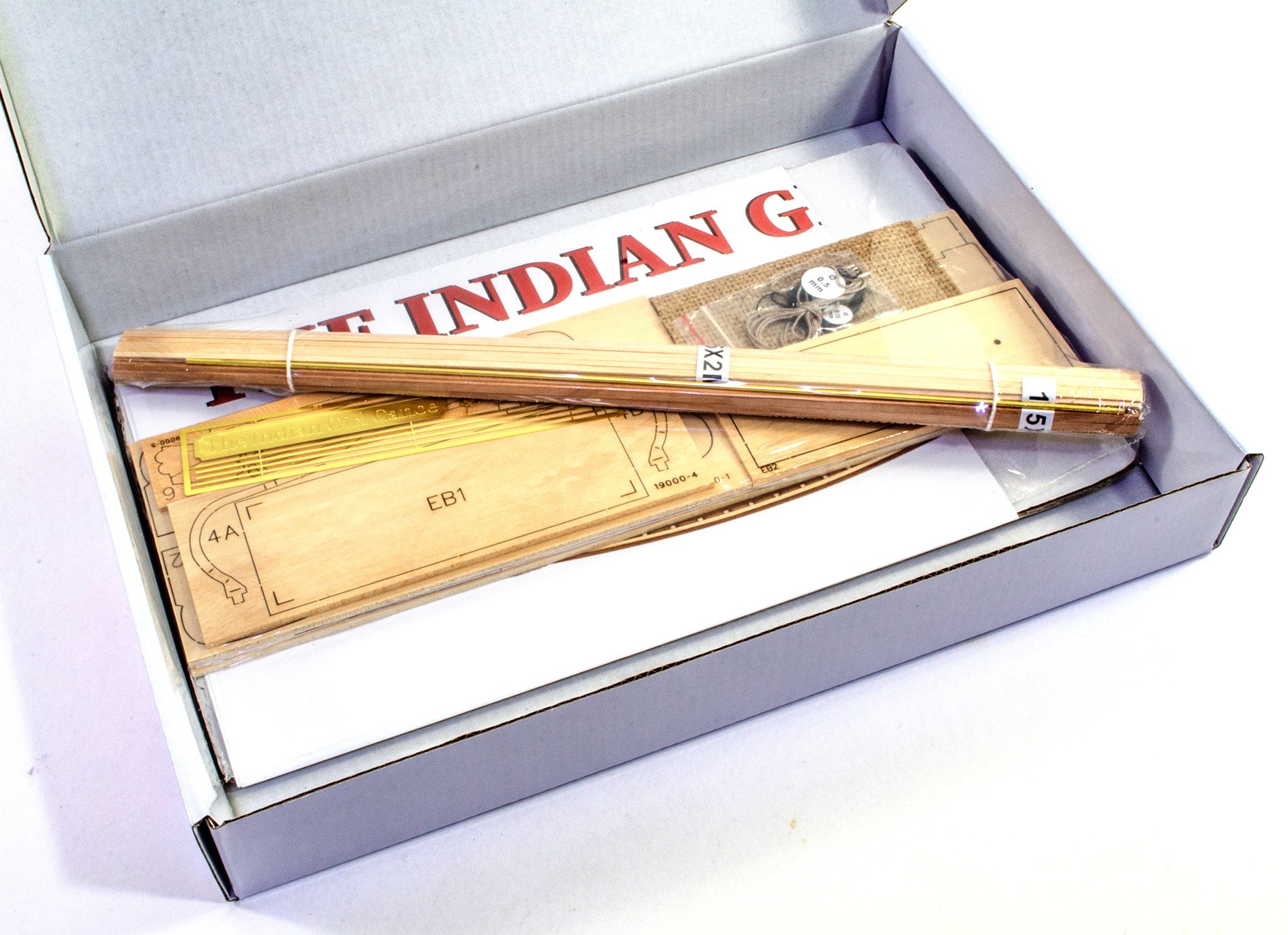
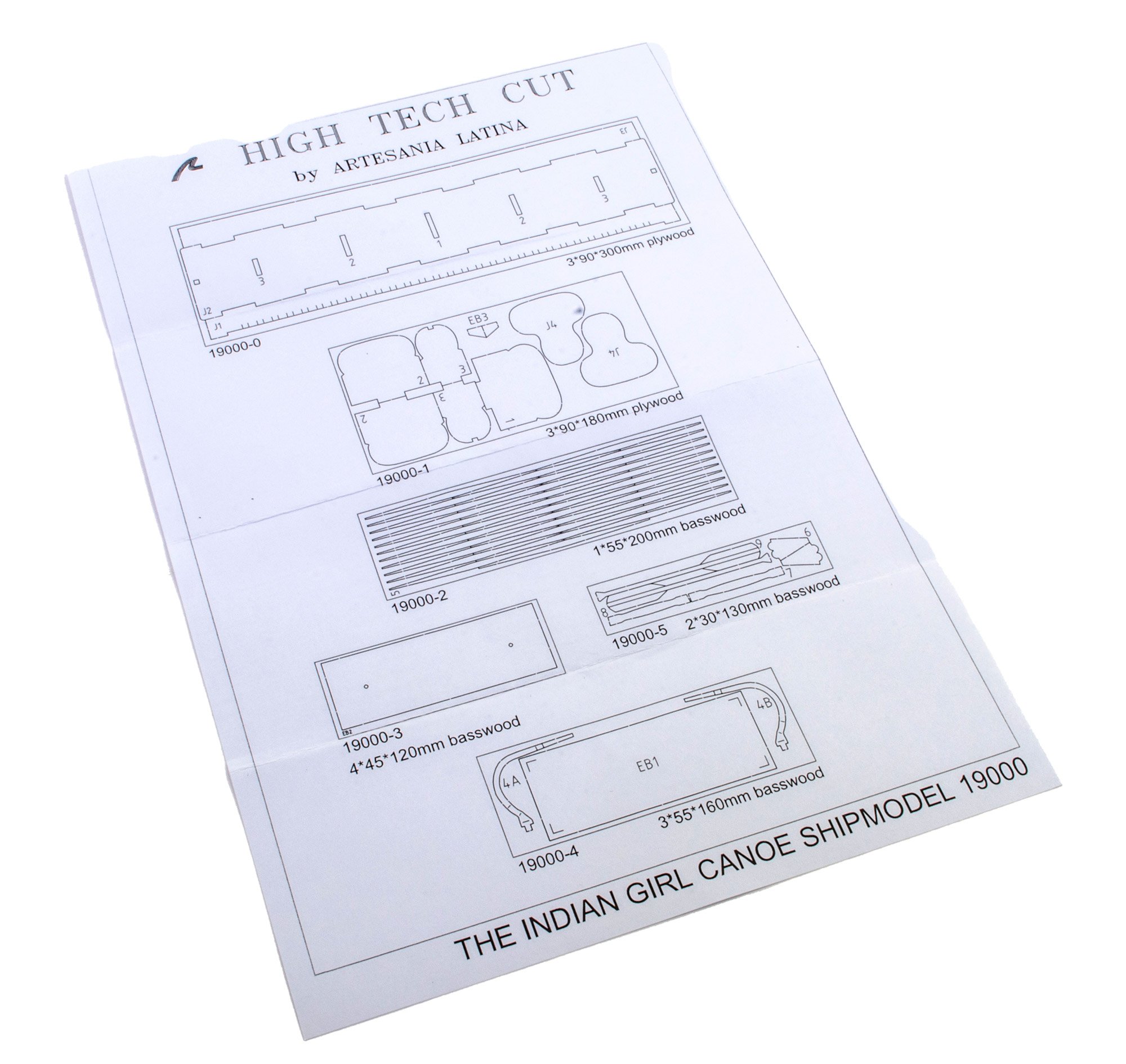
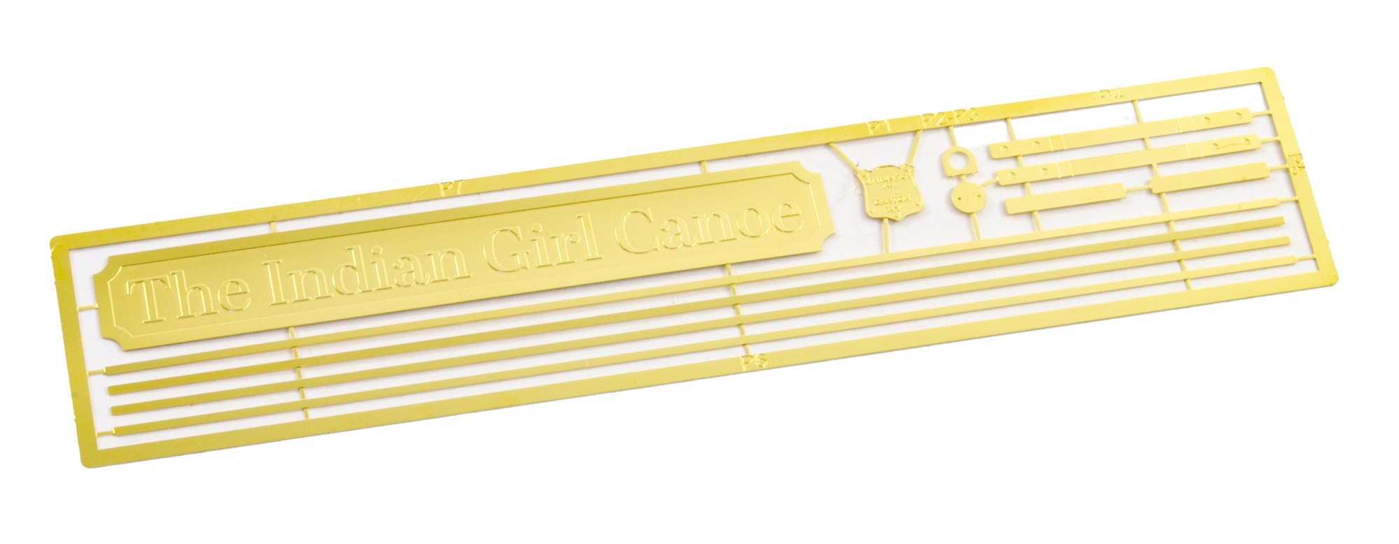
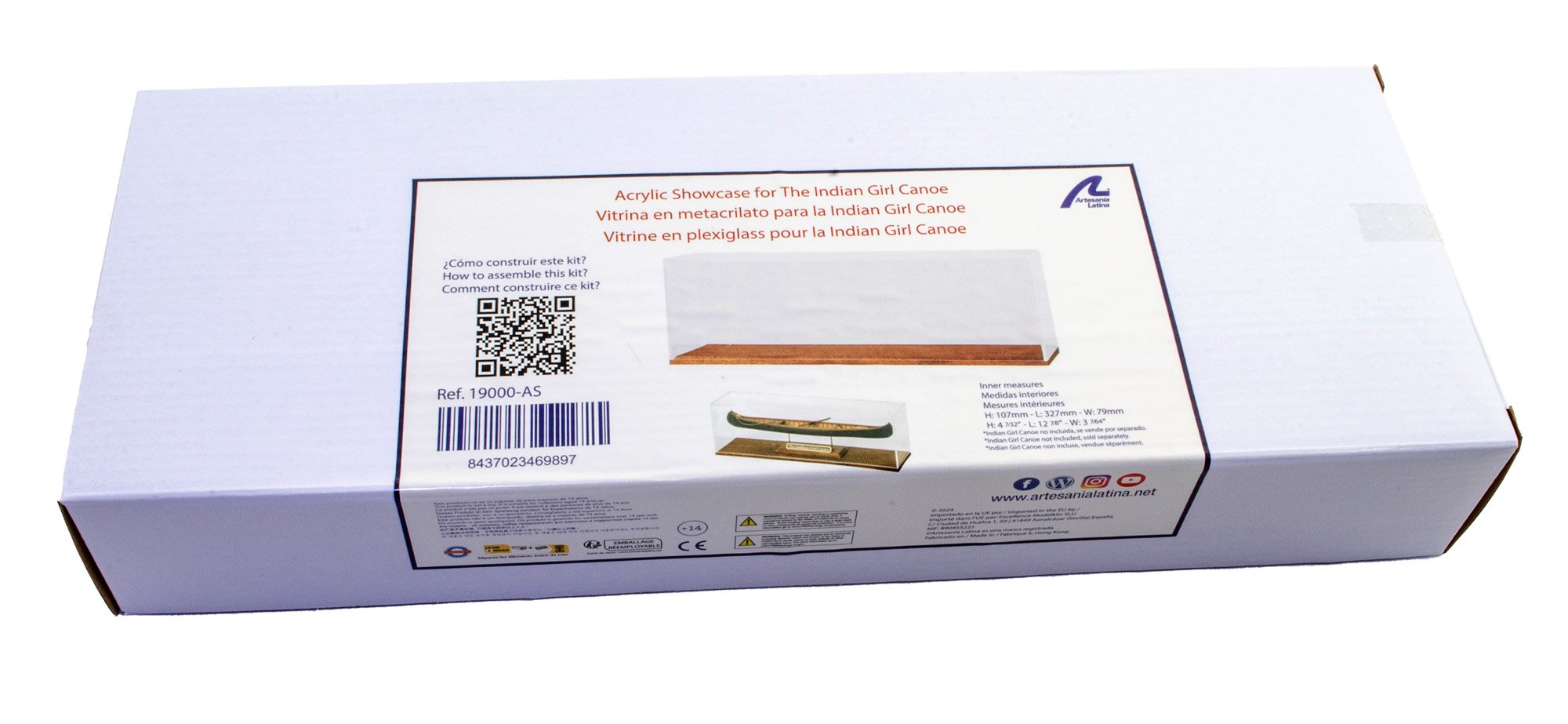
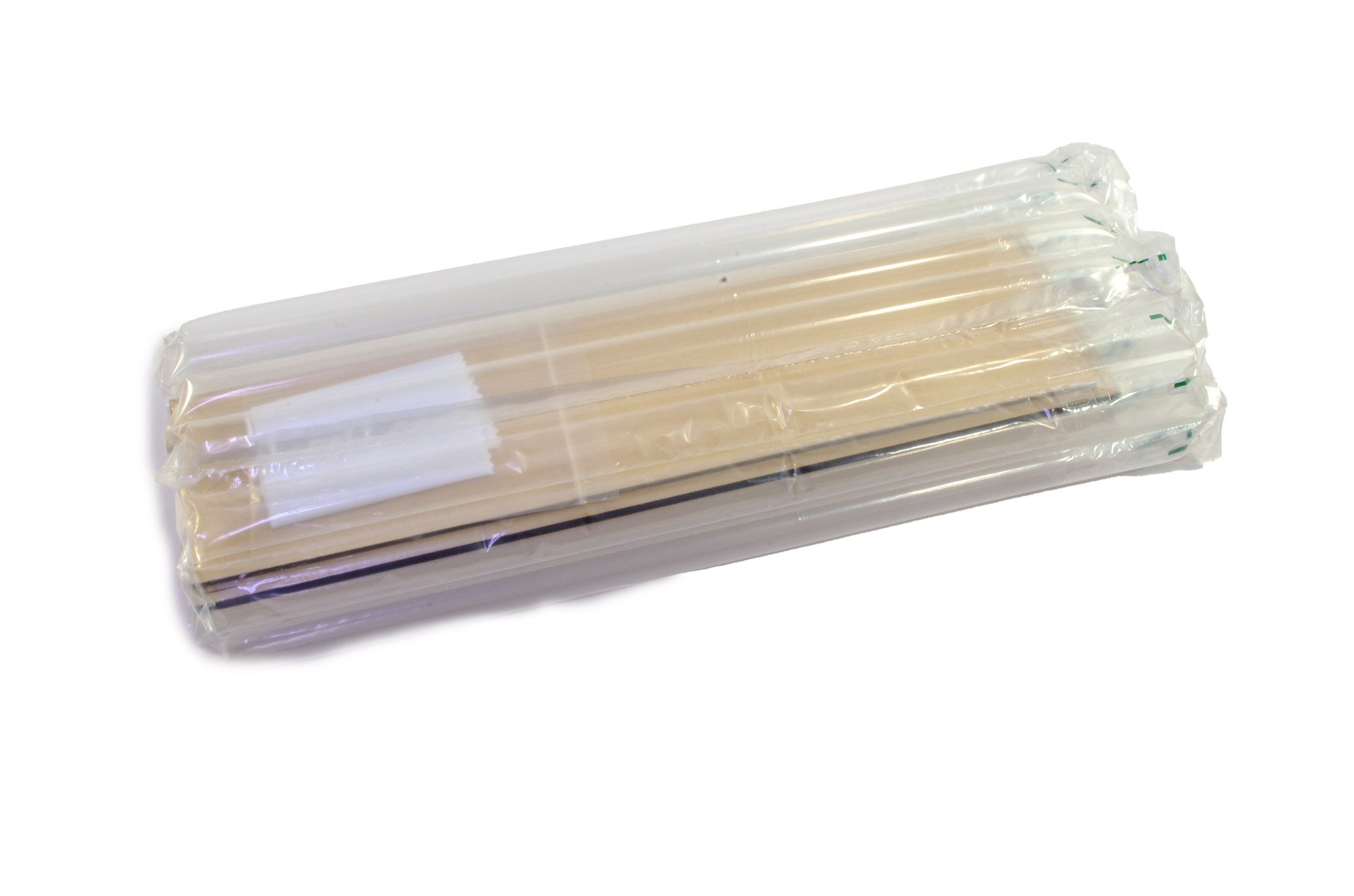
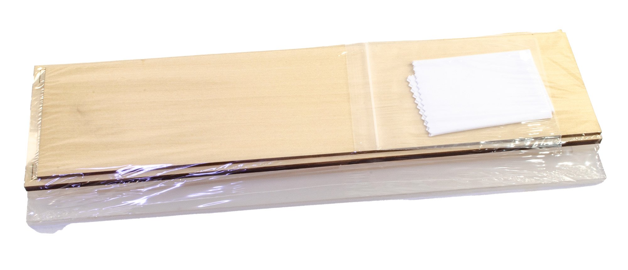
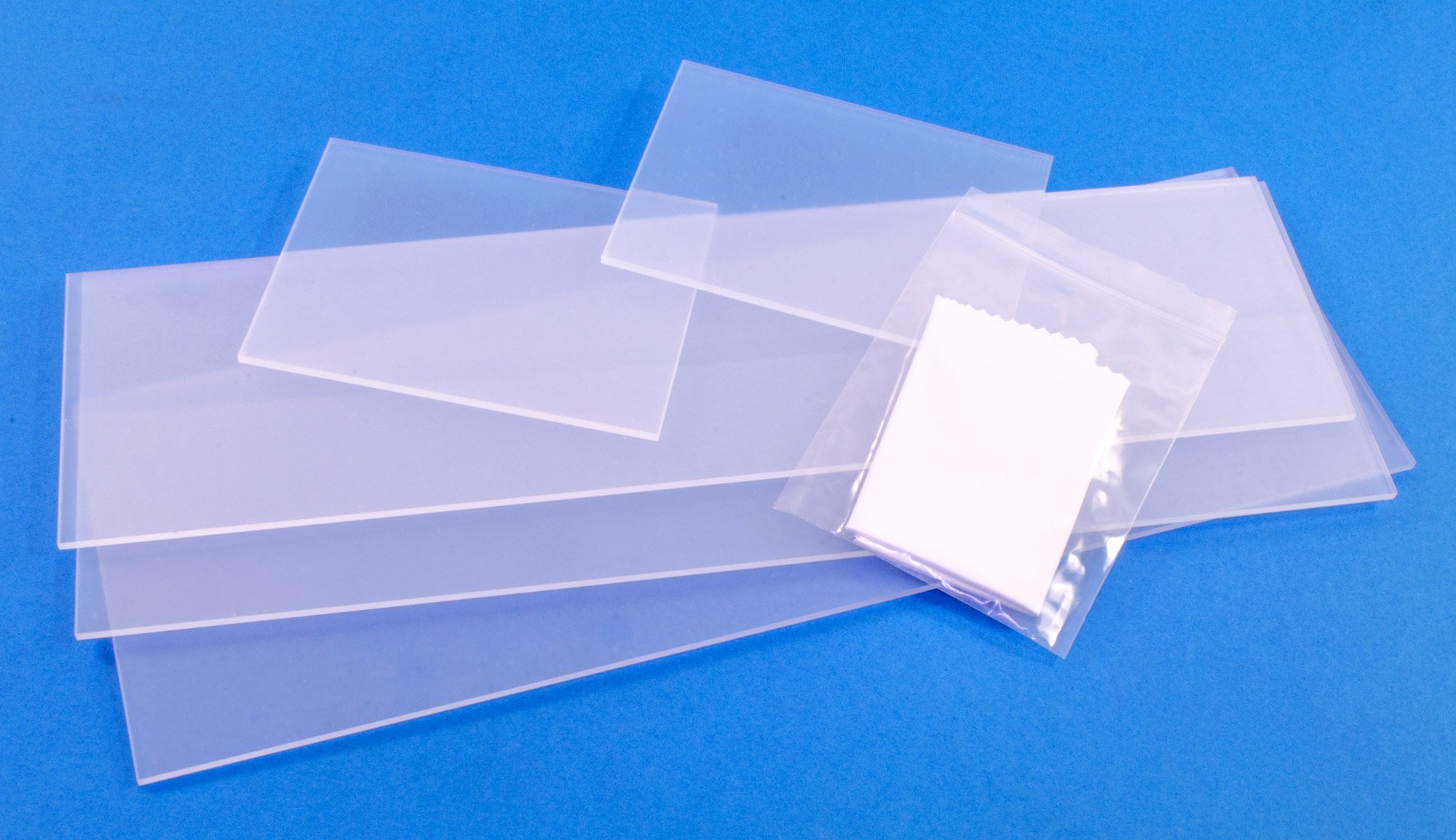
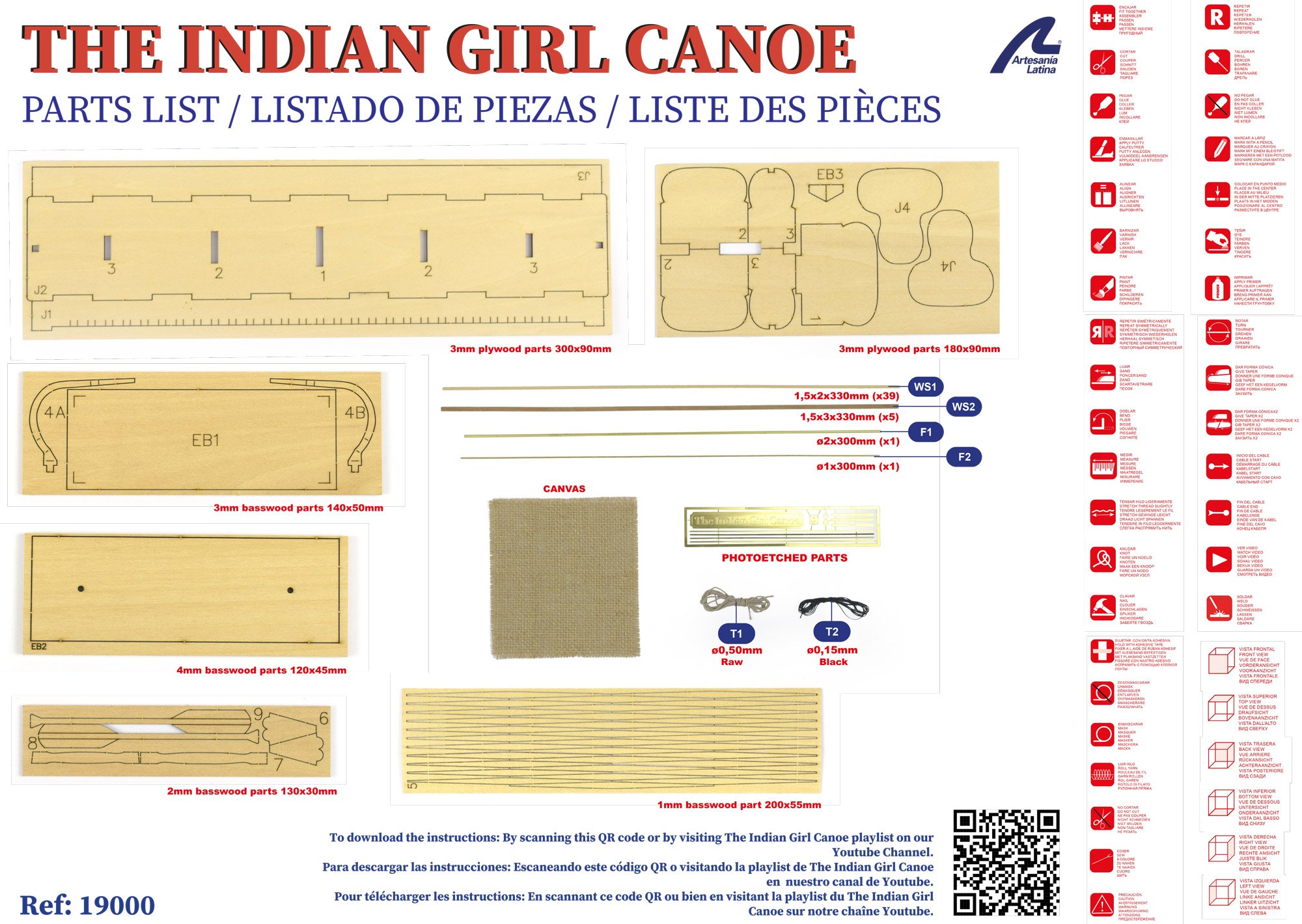
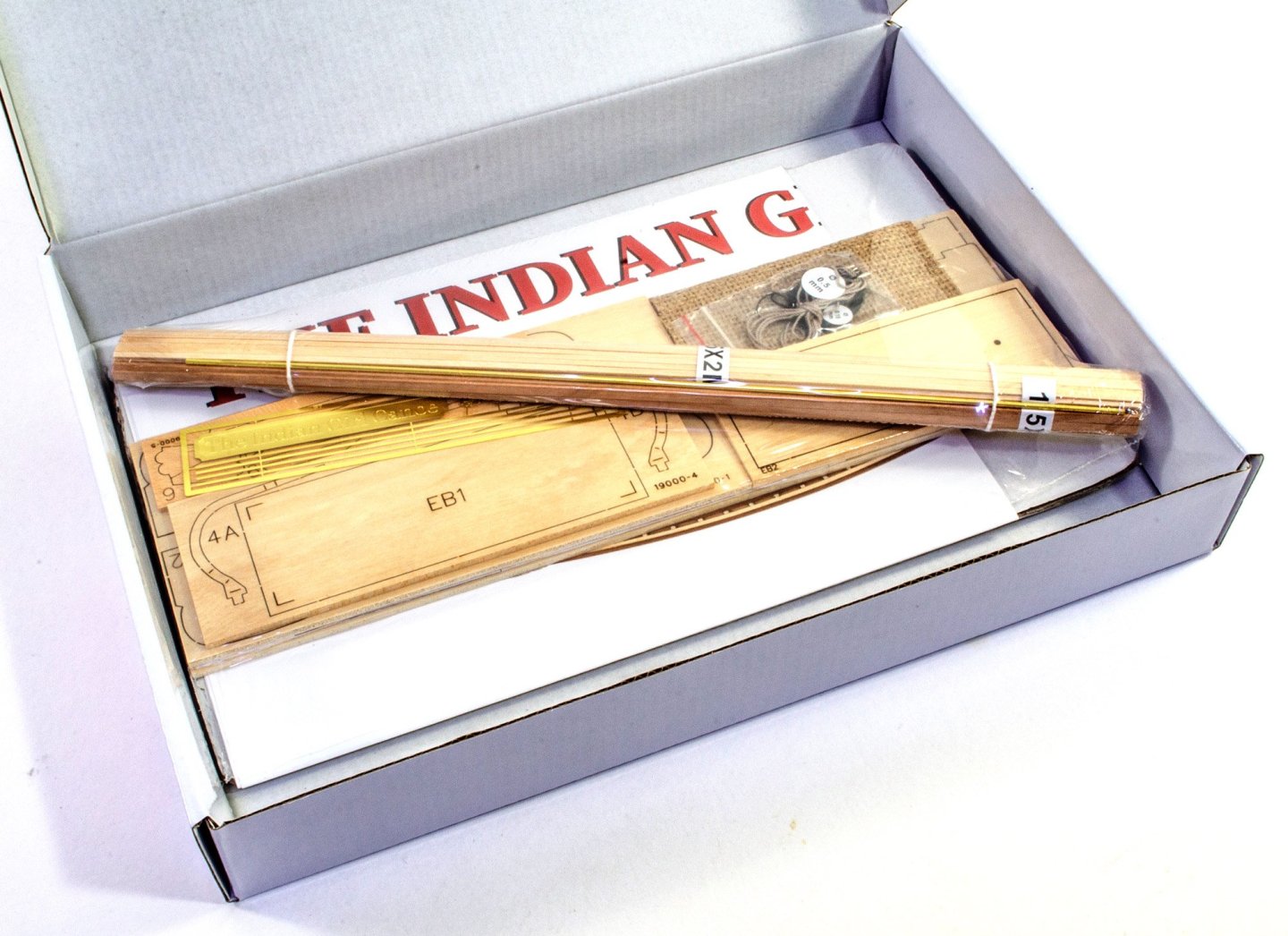
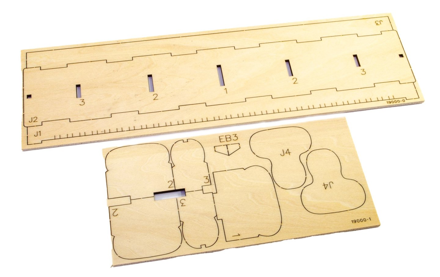
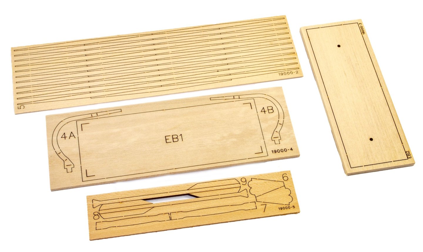
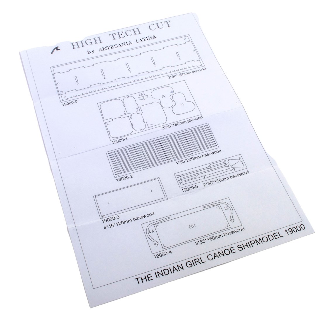
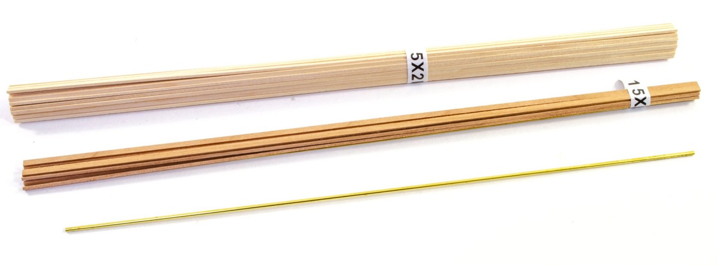
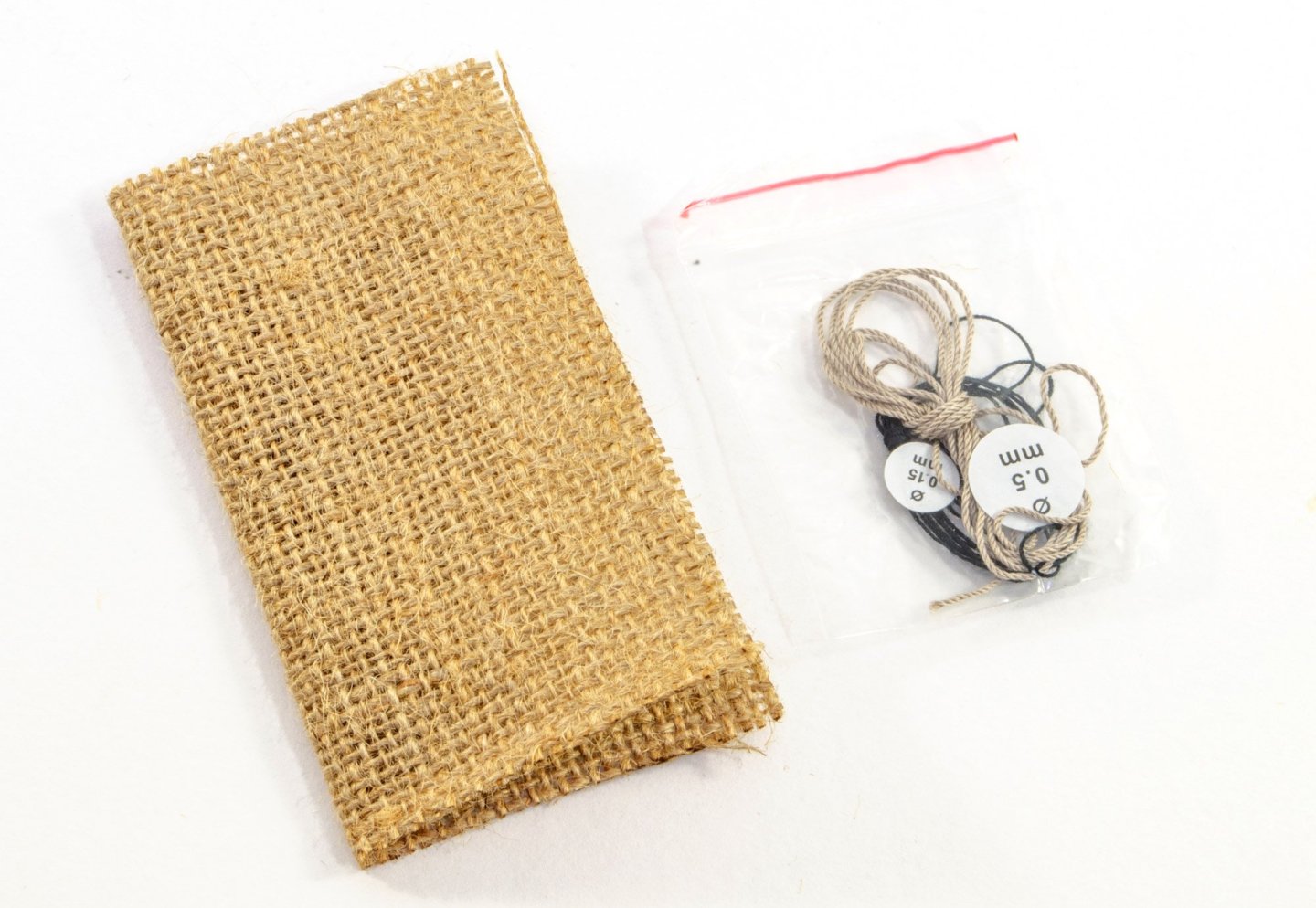
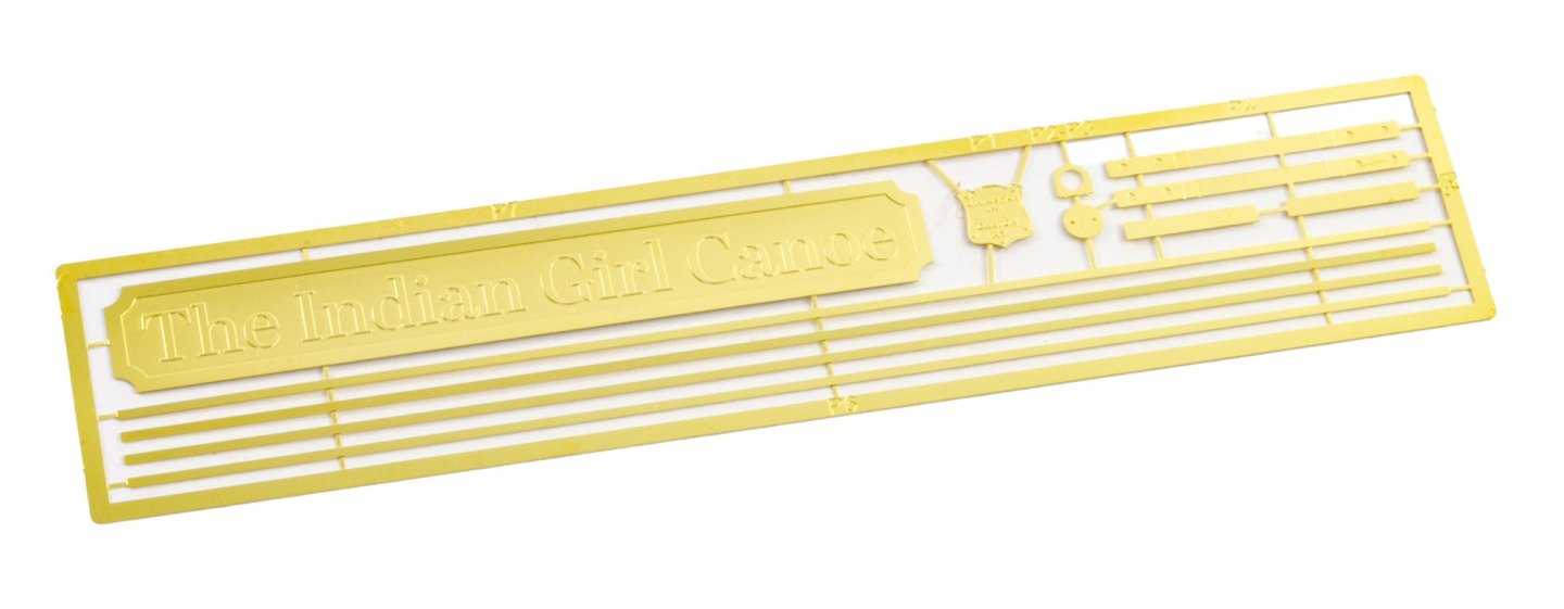
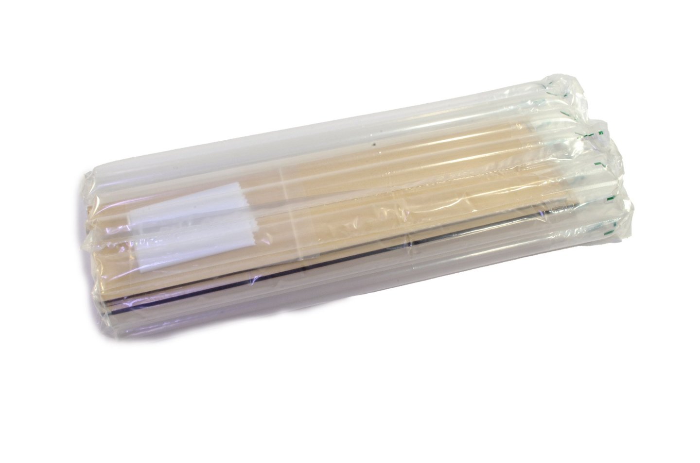
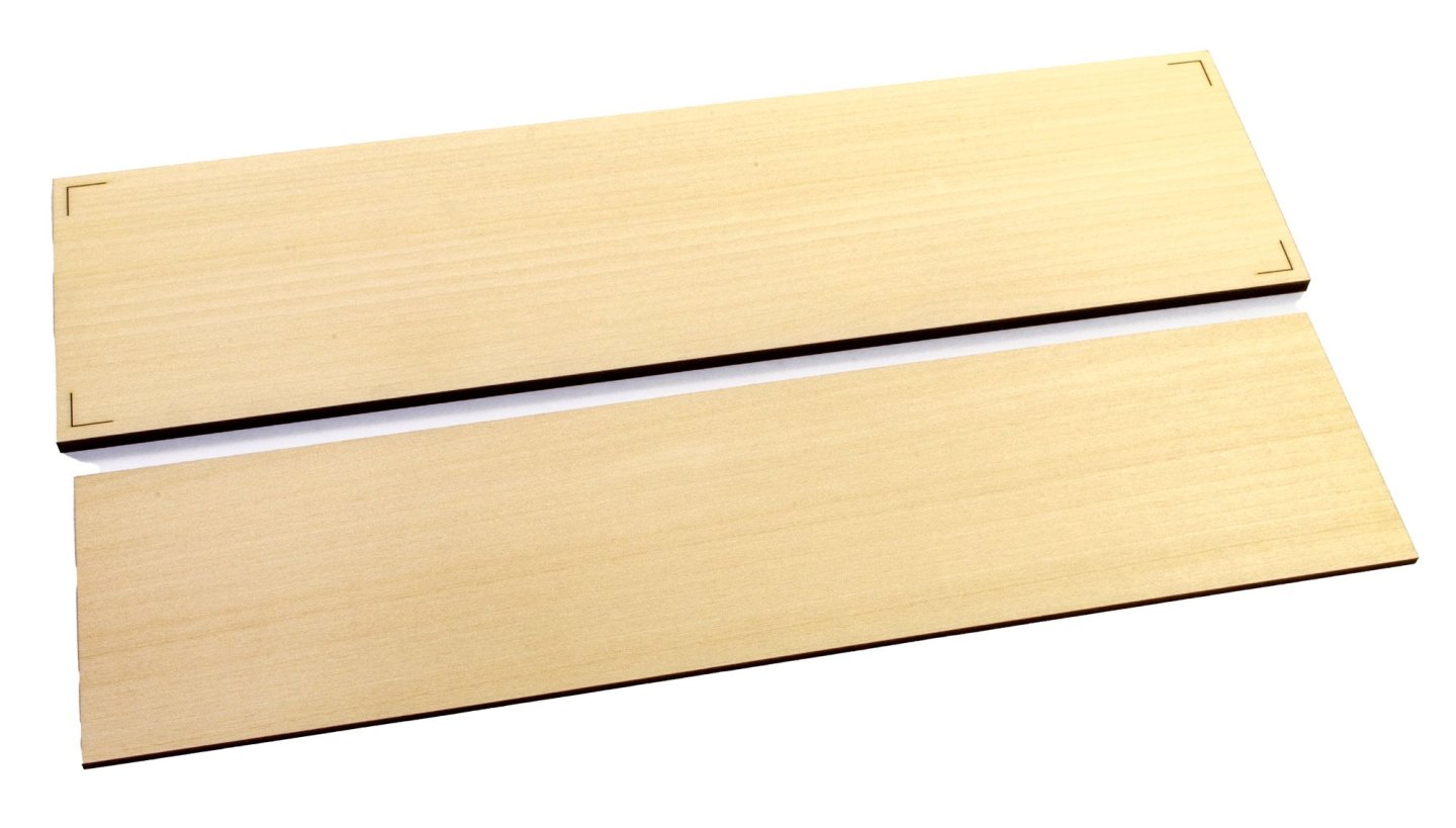
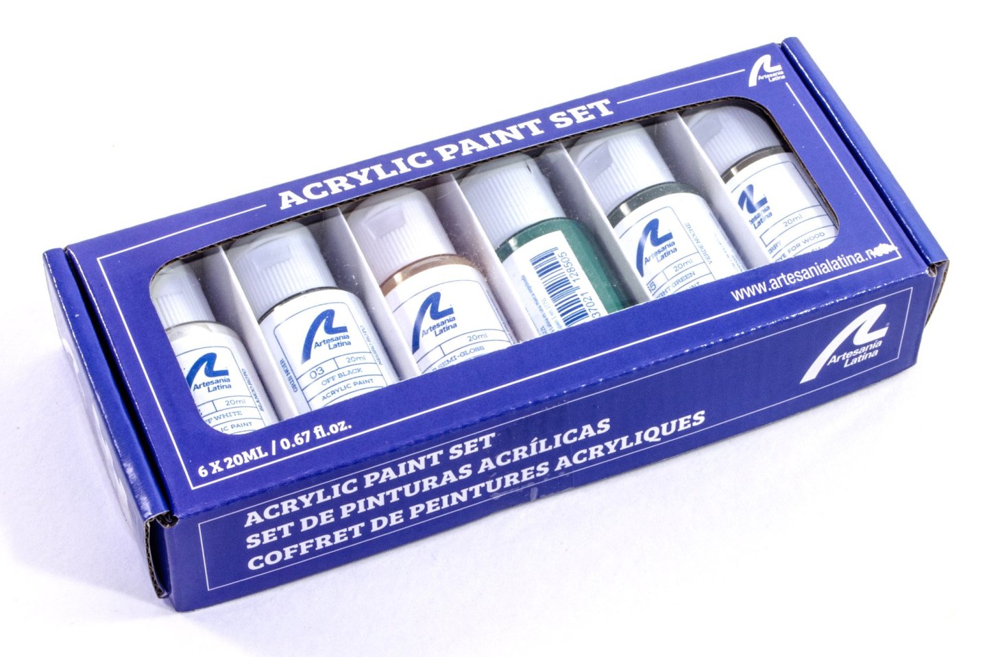
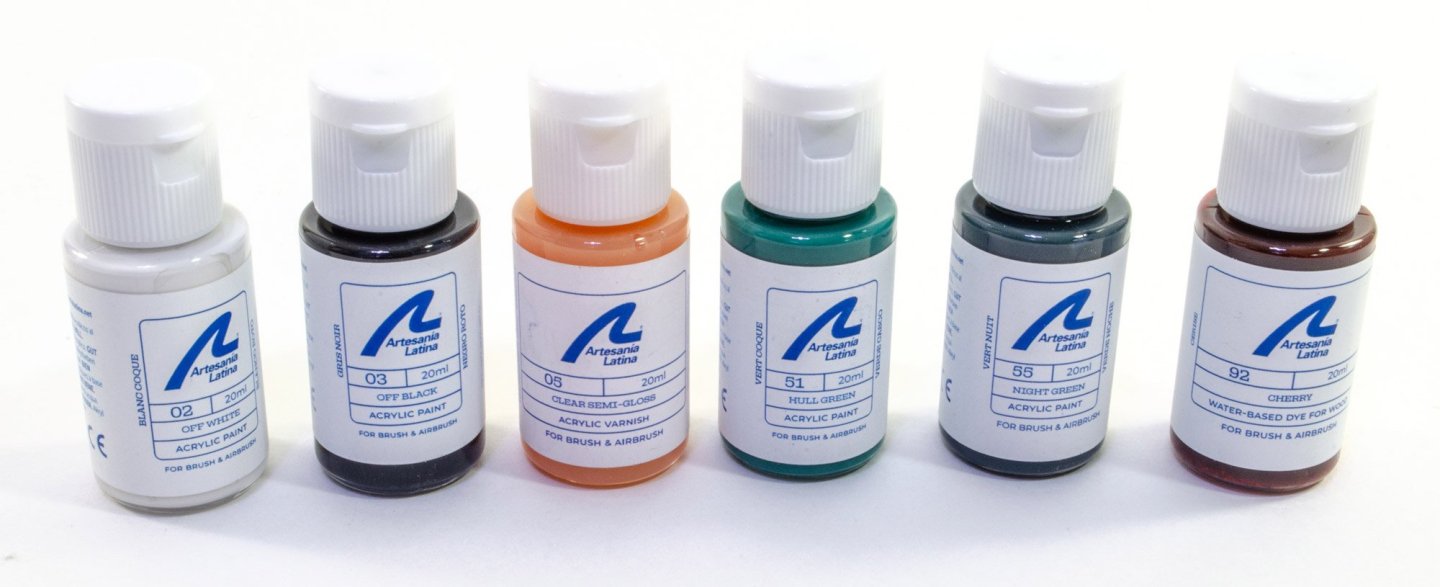
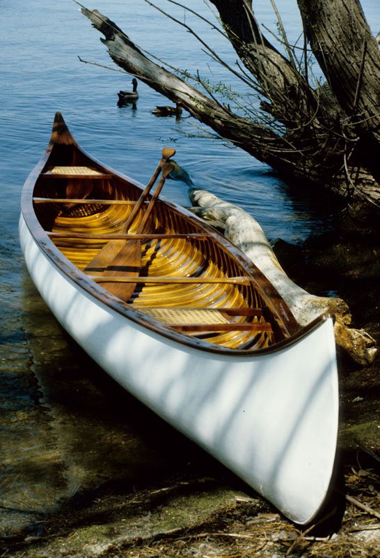
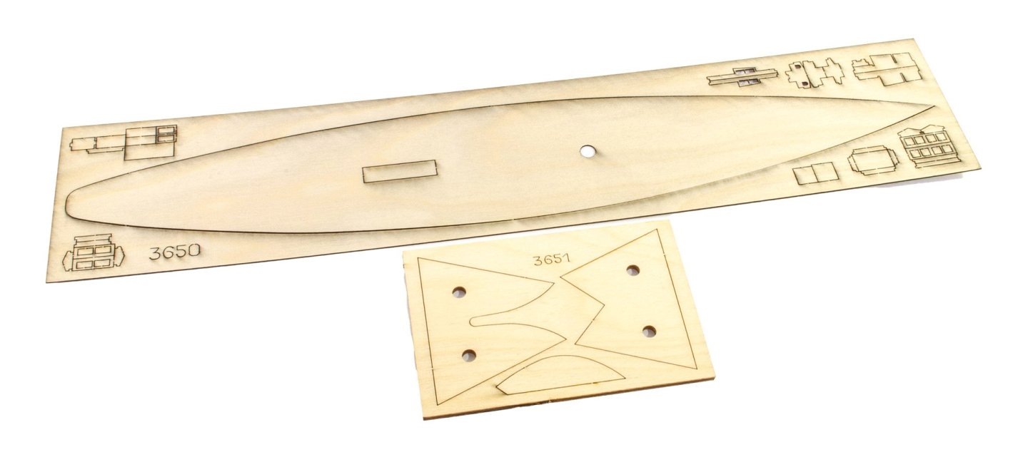
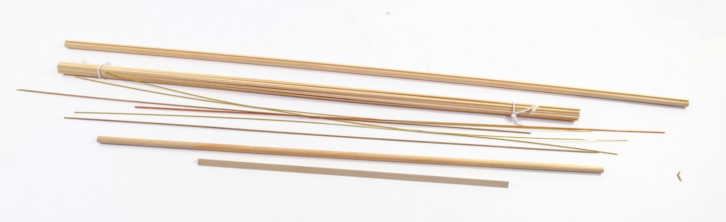
1:16 Indian Girl Canoe Artesania Latina Catalogue # 19000 Available from Artesania Latina for €54,99 History Famous for appearing in numerous American Indian films, the ‘Indian Girl’ canoe was created in 1902 by J.H. Rushton, America's leading canoe builder. The ‘Indian Girl’ came in numerous versions. Introduced in 1902 and always Rushton's best-selling canvas canoe, the Indian Girl was available in lengths from 15' to 18'. Offered in Grade A (two-piece gunwales and pocketed ribs) and Grade B (heavier inwales and thin outside rails and rail caps). Rushton died in 1906. His widow and son incorporated the business and remained in operation until 1917. Canoes and boats built between 1906 and 1917 can usually be identified by the presence of a "J.H. Rushton, Inc." brand or tag. Sometime after the Rushton factory closed in 1917, Joseph Leyere, a noted boat builder from Ogdensburg, New York, acquired the Indian Girl moulds and the rights to build them. He marketed these under the "Whistle Wing" trademark of the St. Lawrence Boat Works until sometime in the late 1920s. (Abridged from the excellent Wooden Canoe Museum website). The kit This is a new release from Artesania Latina. I'm not entirely sure which of the incarnations of the Indian Girl canoe it represents, but it clearly appears to look like the one in the photo I added above. That's good enough for me. This quite inexpensive kit will create a model which is just over a foot (30cm) in length, at a scale of 1:16. The kit is packaged in one of Artesania's easily recognisable top lid boxes which has some images of the completed model, including detail shots. The nature of this kit means that there aren't oodles of parts sheets within. Instead, there is one small pack of cellophaned parts, and a bundle of strip wood/metal tube etc. No instructions are supplied in the kit as it's expected that you will follow the online build videos. That could be a little contentious for those who want a paper copy and aren't good with using online resources to build a kit. Let's take a look inside the bundle. There are 6 sheets of wooden parts. The first two, seen here, are for building the jig/buck onto which you will plank the canoe shell. Please note the engraved marks on one of the sides of the main jig. these are for transferring the marks to the strip piece which will form the lower keel and determine the position of the inner ribs of the canoe. The formers don't have a centre line engraved on them for some reason, and you will need to add that yourself. The two bulbous parts (J4) are for helping to form the inner ribs before gluing them in place. EB3 are for mounting the nameplate to the plinth. Sheet 5 contains all of the internal ribs that you will form around part J4. These are over-length so you can trim them after fitting. The sheet underneath contains the the largest of the two plinth parts, with the small one on the adjacent sheet. Also seen on the plinth sheet are the bow and stern of the canoe. The bottom sheet contains the thwarts, paddles and the bow/stern turtle decks. While there aren't too many pre-cut parts, but there is a reference sheet included which has them all printed on. The remainder of the kit materials are in strip form, including some brass tube and rod which will be used for mounting the canoe to its plinth. The lighter material is for planking the canoe and the darker is for internal details as well as keel, seat frames etc. The hessian fabric is for adding to the seat frames, creating the cushion. The rigging cord is for the canoe tether line and also the handle grips on the paddles. As well as the name plate for the plinth, there is also an ID shield for the canoe itself and parts for the tether, plus further parts for running on the outside of the completed keel. As there's no manual, you can access the online instructional videos by this link. Please check it out: Conclusion While this I a very simple kit, the completed model does look incredibly nice and won't take up much valuable shelf space. It would make a very nice desk ornament too. A very inexpensive and nicely designed little kit which will give the modeller a good number of pleasant hours in the workshop. RELATED ITEMS Artesania have sent extra items which relate to this kit release, namely a display case and a set of paints which are also specific. Methacrylate Showcase for The Indian Girl Canoe Model Purchase from Artesania Latina for €59,99 The case for the canoe model is quite specific in its dimensions, and all parts are carefully packed into a robust bubble bag so the delicate acrylic won't be damaged. Inside the sleeve, all parts are also wrapped in cellophane. There are two parts to the base, creating a recessed lower plinth onto which the clear assembly will sit without need for glue. All panels of acrylic are covered on BOTH sides by a peelable protective cover. Also note that a cleaning cloth is provided too. The online instructions for this case show the sheets being taped together and then thin CA being run down the seams to permanently secure them. This does give me a little anxiety in case the glue leached from the joint and onto the tape which is holding the panels together. And then there is the risk of clouding. I know you can use odourless CA, but I would perhaps opt to use a glue which is specific for Methacrylate, and clamps/tools for making sure you get all angles correct. This is essential to make sure the last part fits. The tape method does mean you test all panels together before CA, but I'll leave that decision to you. Paint set for Indian Girl Canoe Purchase from Artesania Latina for €15,99 This acrylic paint set contains SIX 20ml bottles of paint, filler, varnish, and also stain. The colours are specific to this kit, and include the white as an undercoat. All are water-based. The contents are: Off white Hull green Semi-gloss varnish White primer/filler Water based wood dye Night green Artesania's site says the paints are also suitable for airbrushing. It gives no details about this, but assume you would need to thin them at least 50% with water or other thinner which aids smooth acrylic flow in an airbrush. My sincere thanks to Artesania Latina for sending these items to be reviewed on Model Ship World. To buy them, click the links in this article.


-
kit review 5 Cylinder Radial Engine (TECHING) - EngineDIY
James H replied to James H's topic in Non ship-related reviews
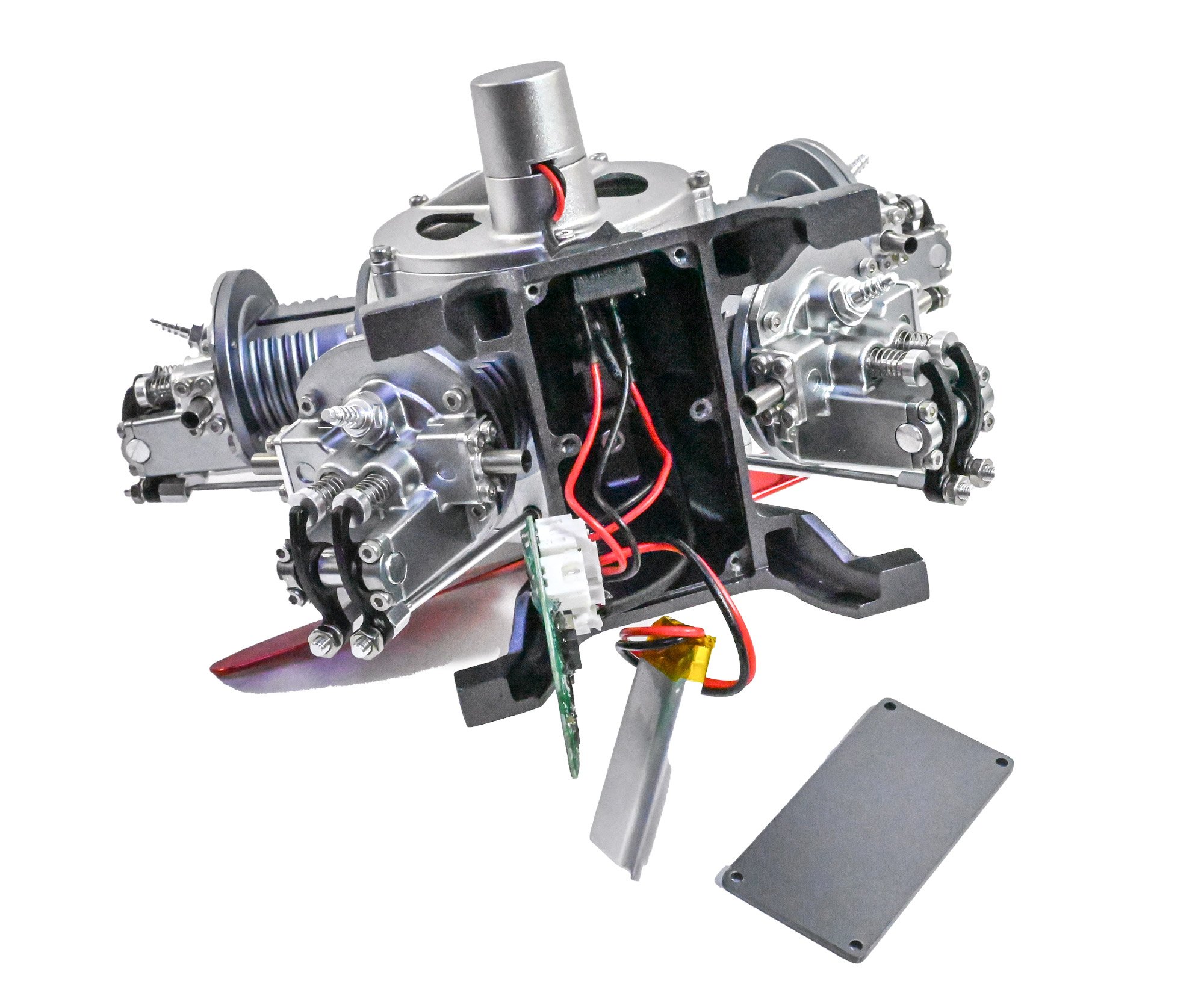
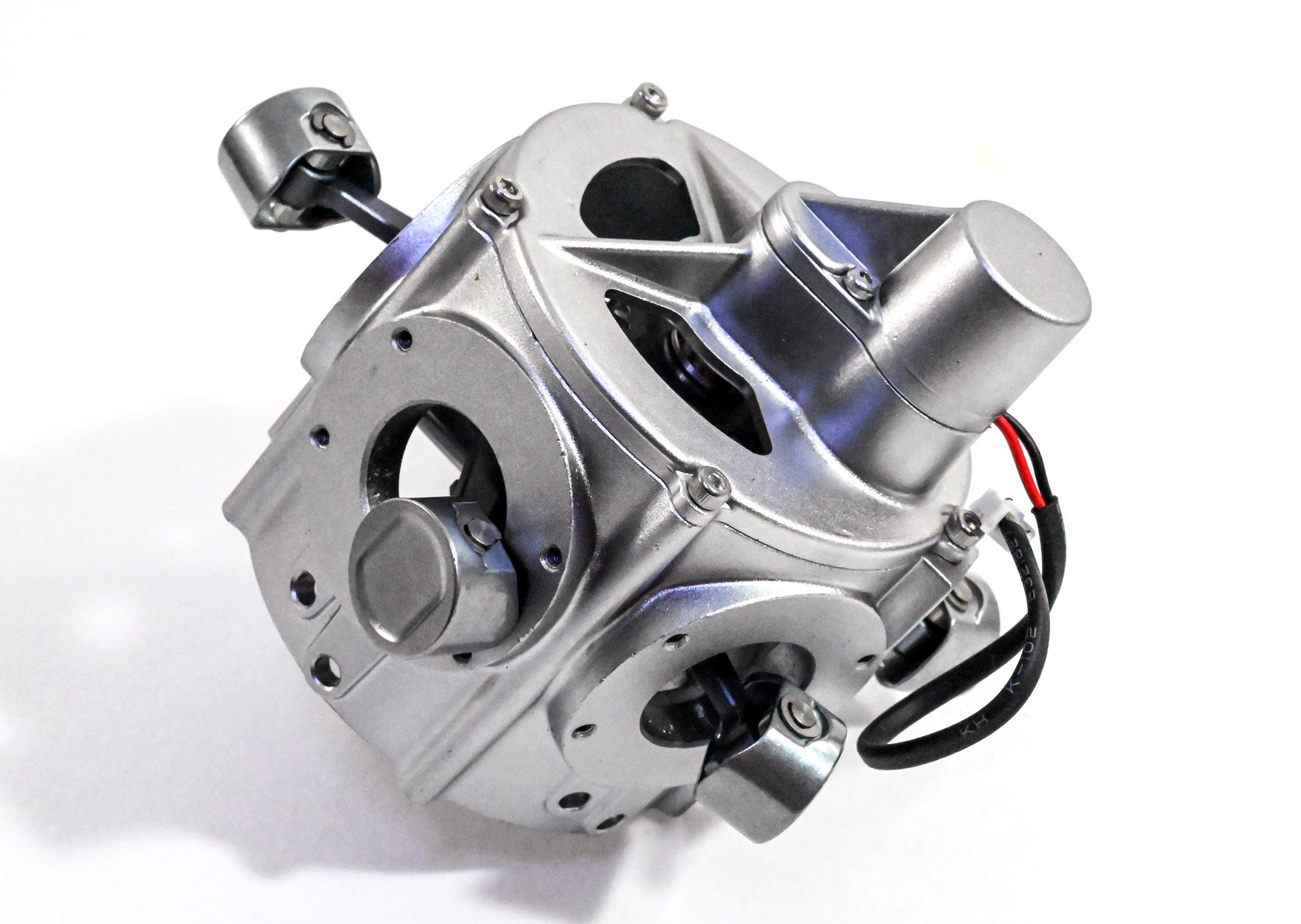
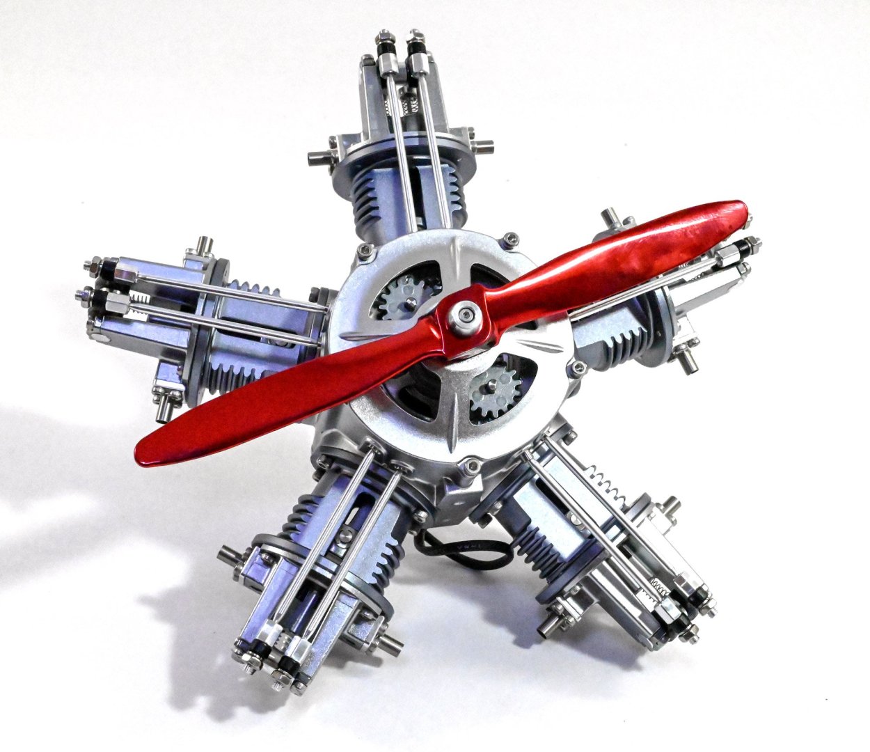
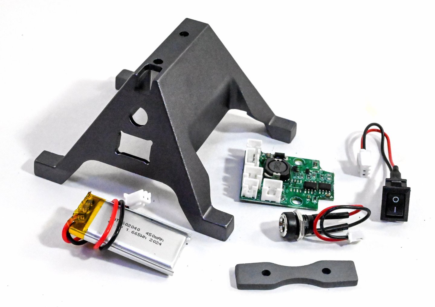
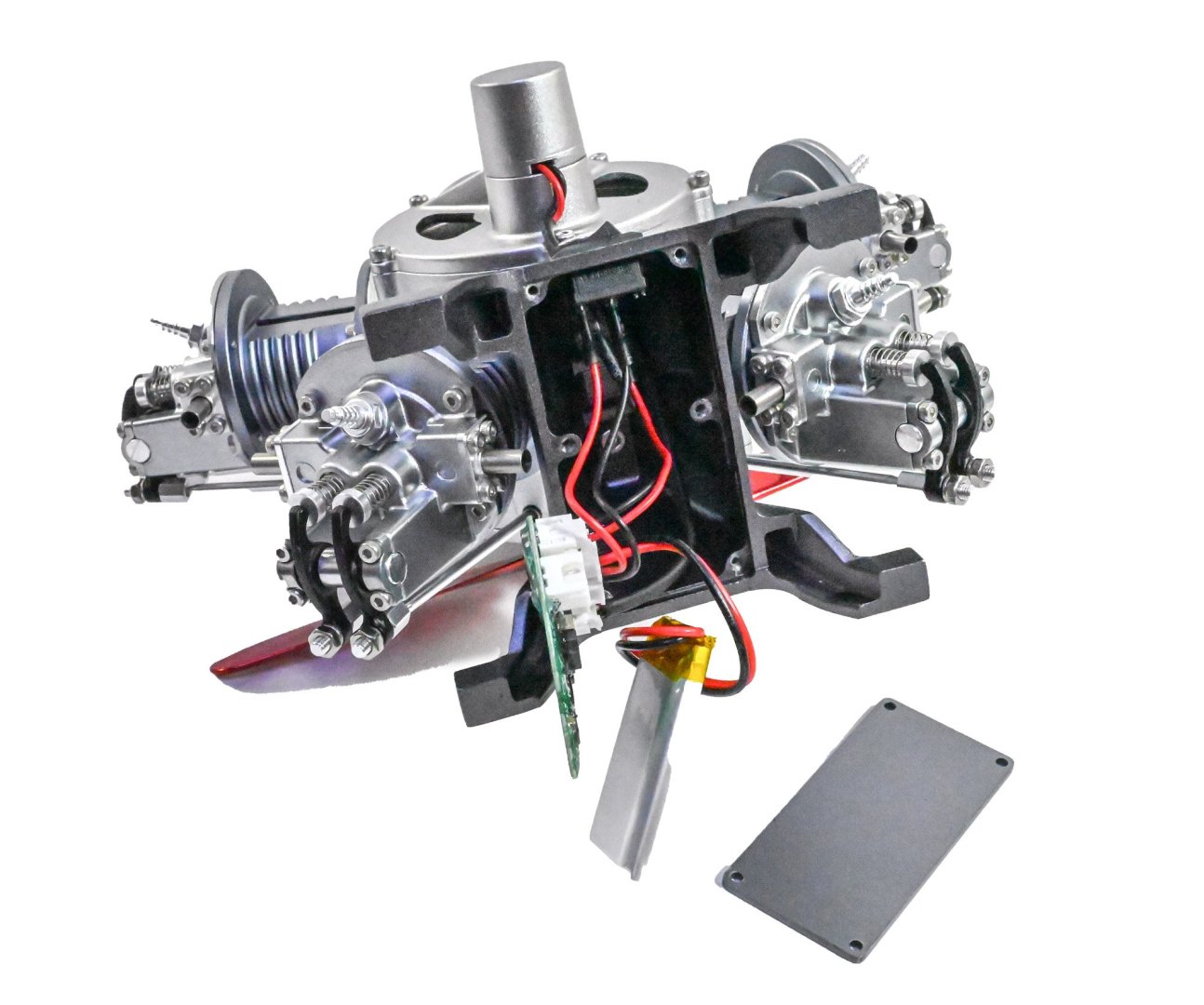
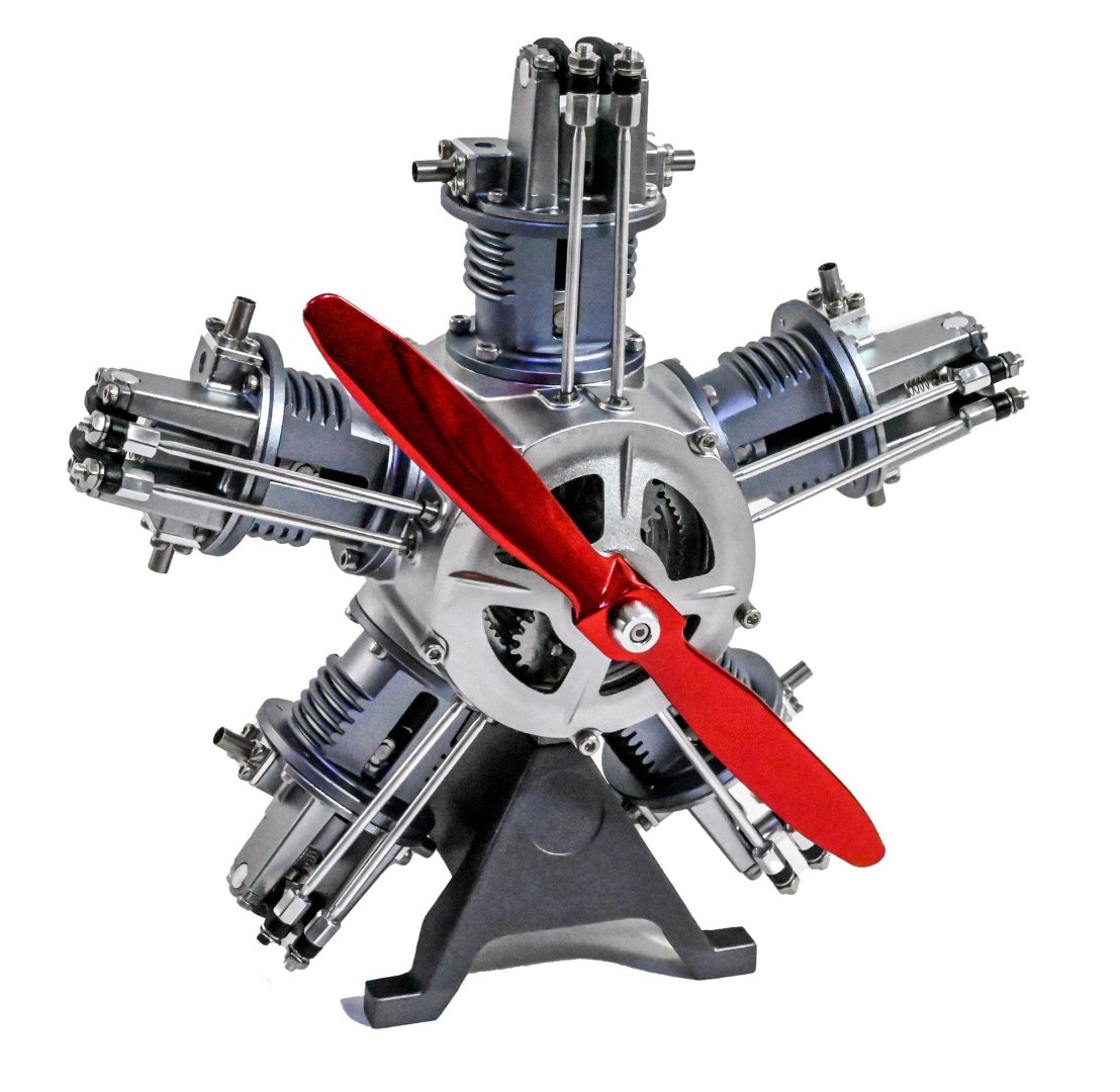
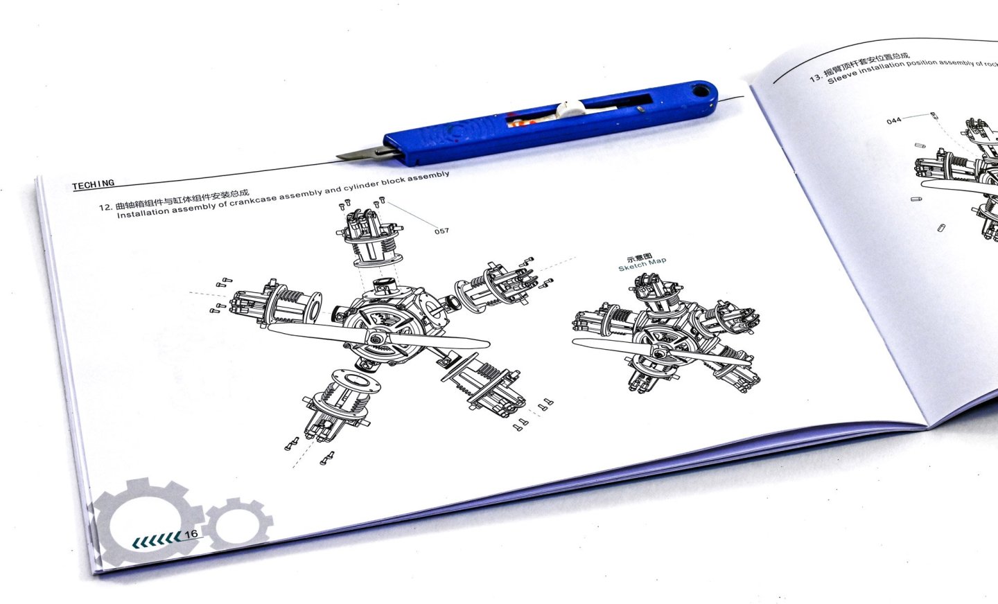
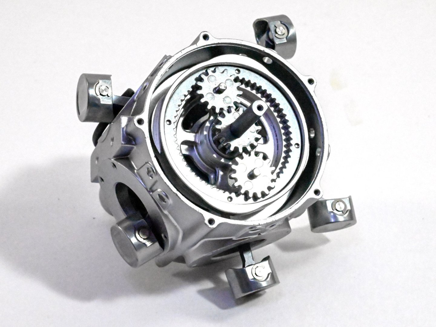
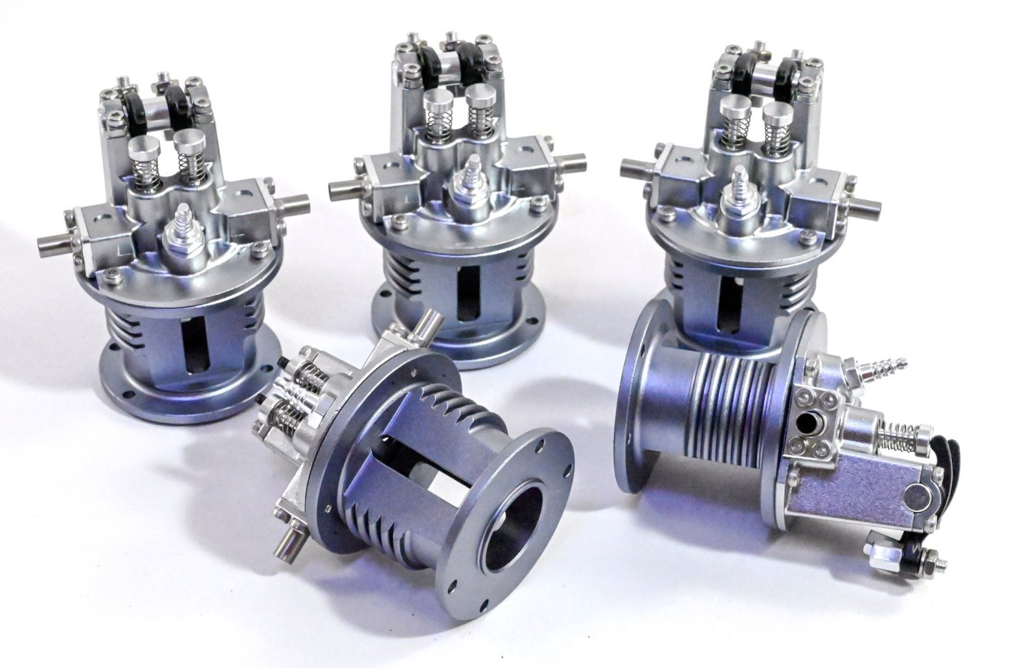
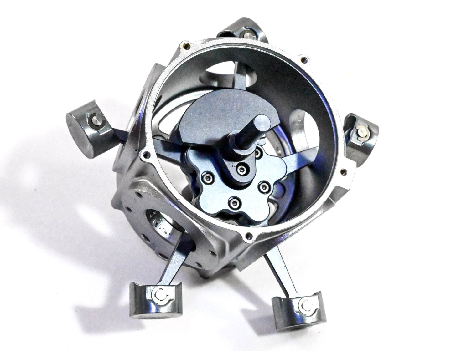
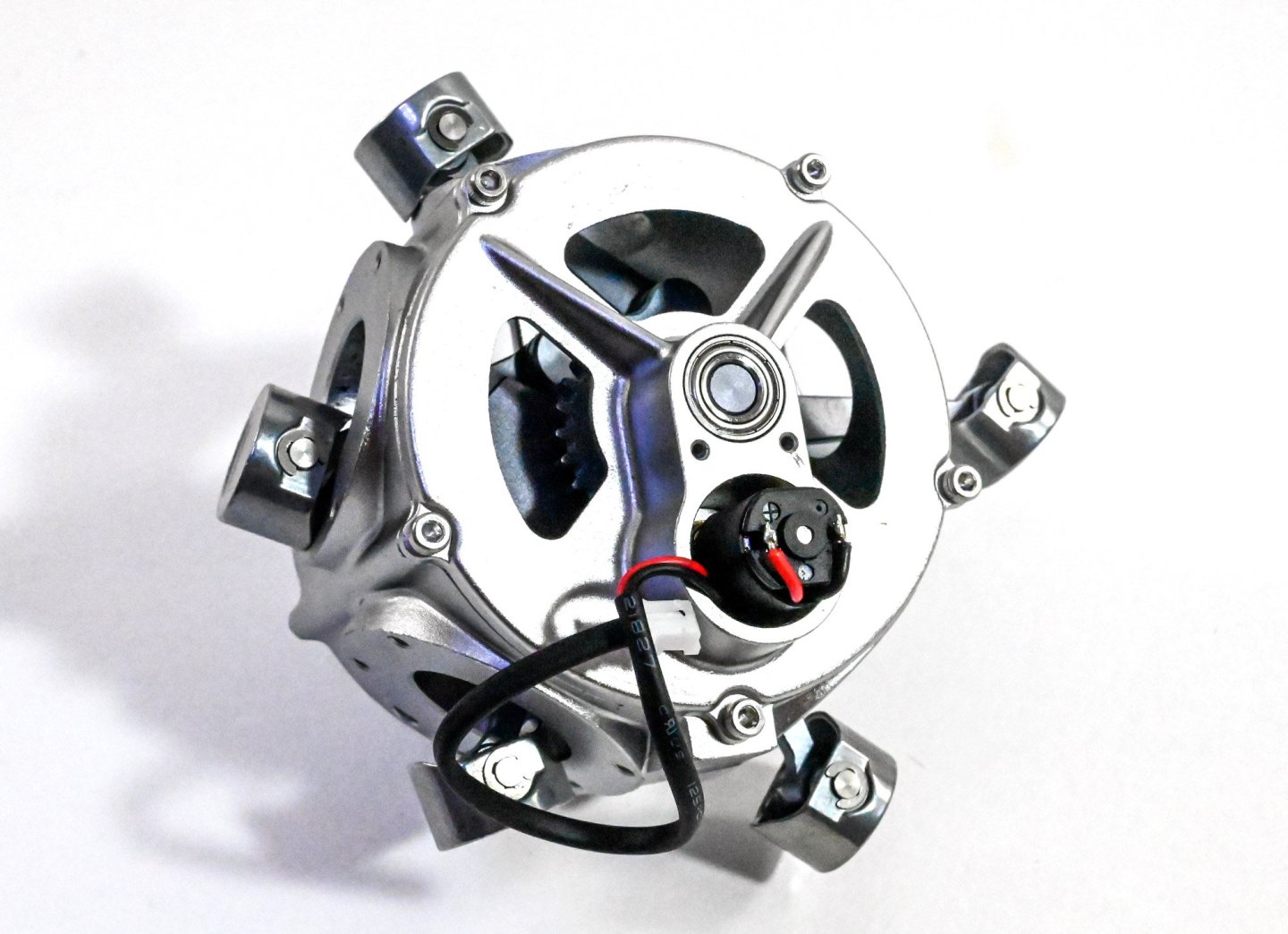
Here is the main event! The model is actually quite large and weighty, and we haven't finished yet. The ejector rods and sleeves are now to be fitted. This is done one cylinder at a time, and needs to the rocker arms to be lifted to allow the ejector rods to sit. The base is now fitted, and a spacer mounted between the base and engine. Once fitted, the battery charger port, switch and motor cables are threaded into the base. The cables are then plugged into a control board, along with a battery pack. The circuit is then screwed into the base and a cover fitted to hide it all. The kit also includes a USB charging cable too (not shown). COMPLETE! And here is a video I made of my review build. The instruction manual is clearly illustrated and the average builder should find zero difficulty in following each stage. Conclusion I didn't know what to expect before seeing this kit in the flesh, and I was very pleasantly surprised. I'd had a hankering for building something like this for a while, but I suspect the mixed reviews I'd seen were from cheap copies. This kit very much surpasses my expectations in presentation, quality, and also the final result. This model took me about 5hrs to complete, but that's also because I was setting up photos of each stage. I think it's fair to say that the manufacturer expectation of about 3hrs is reasonably accurate. The instructions are very easy to follow and should present no problems, even to a beginner who has no sort of modelling or engineering experience. All parts fit perfectly together with no issue. The only things I would criticise are the hex keys which are a little soft and round off easily, making tightening the screws hard. Also, there is no lube in this kit any longer, so you will need to source your own. In all, a fantastic kit. My sincere thanks to EngineDIY for sending out this kit for review on Model Ship World. Whilst not marine-related, I'm more than sure you'd really enjoy this one. To buy direct, click the link in the header of this topic.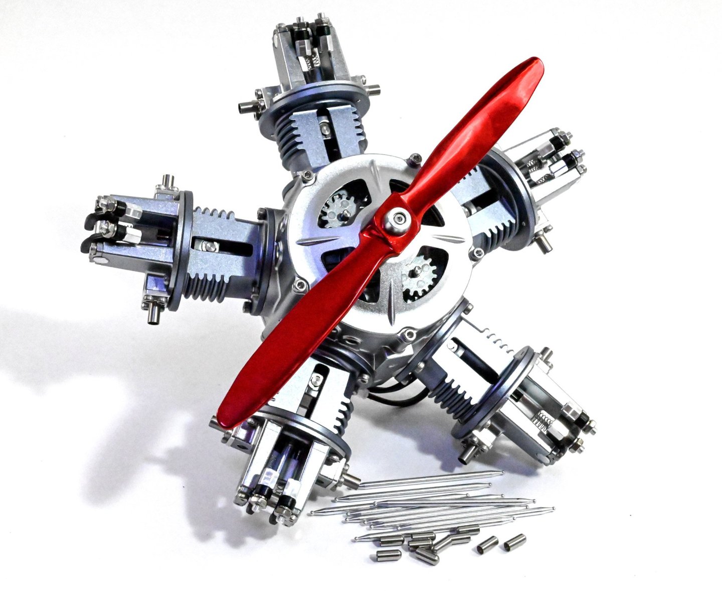


-
kit review 5 Cylinder Radial Engine (TECHING) - EngineDIY
James H replied to James H's topic in Non ship-related reviews
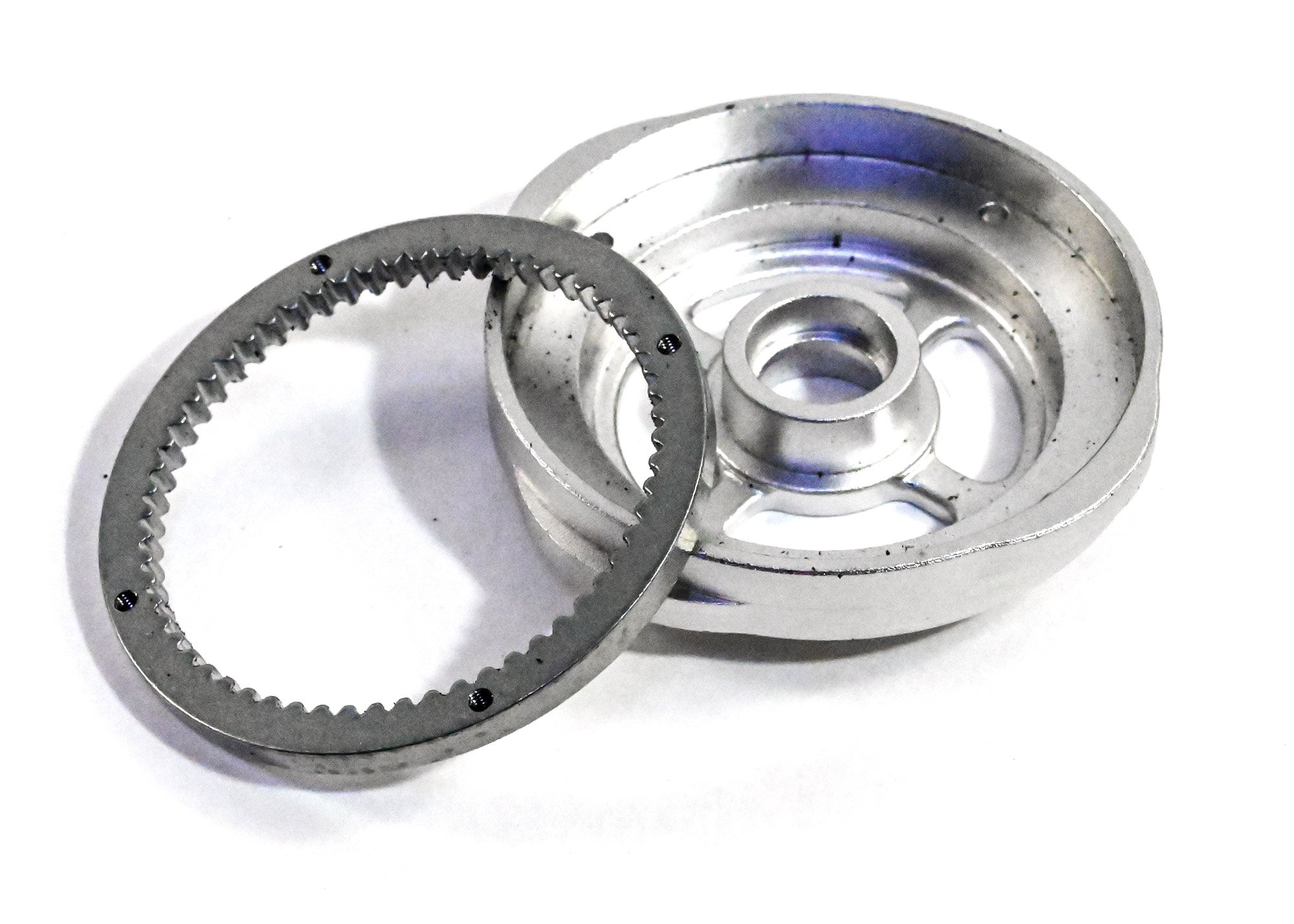
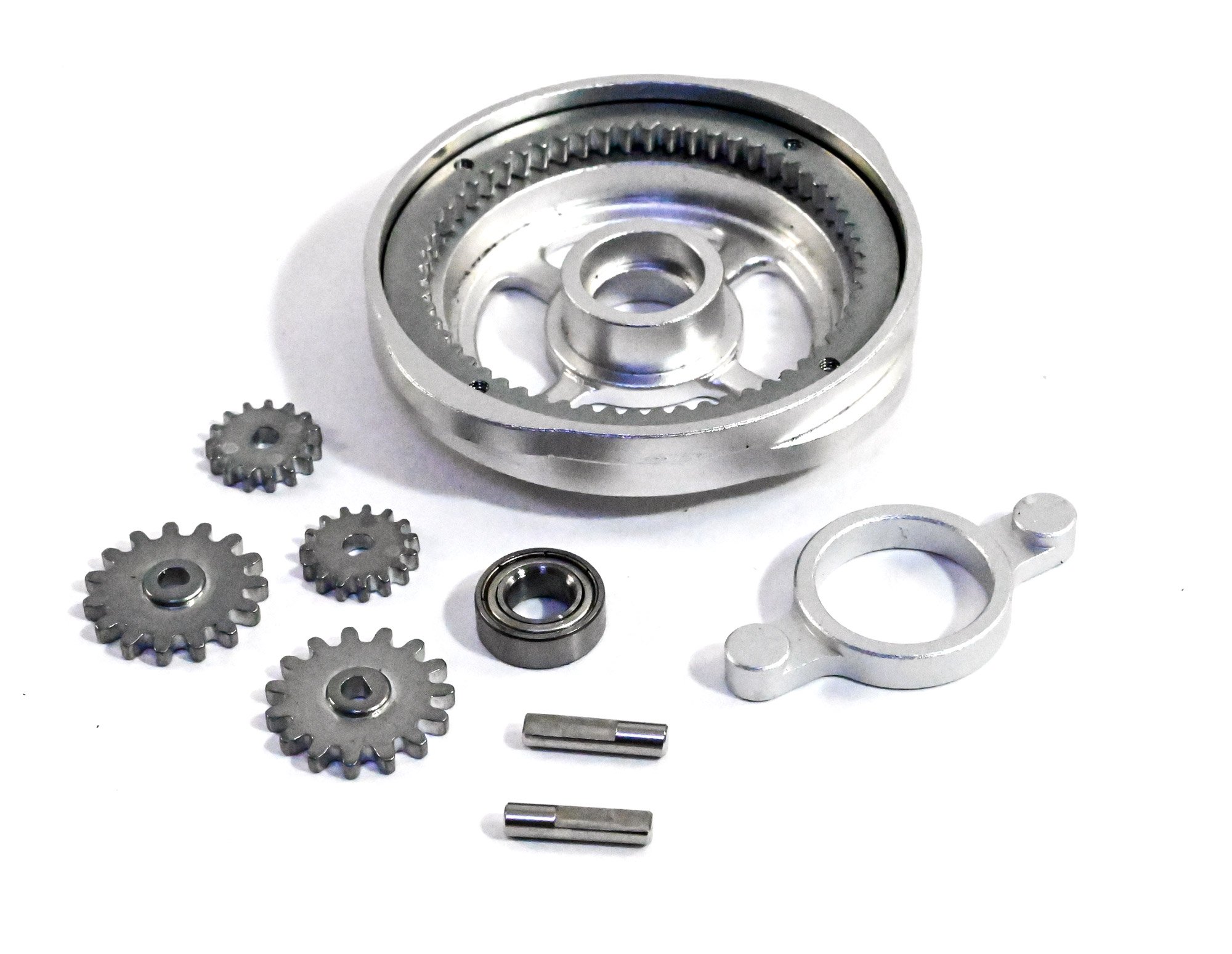
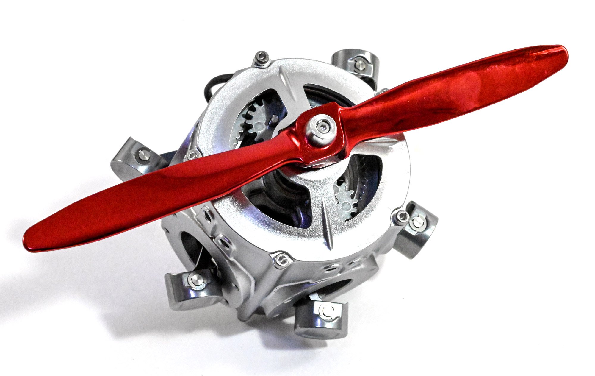
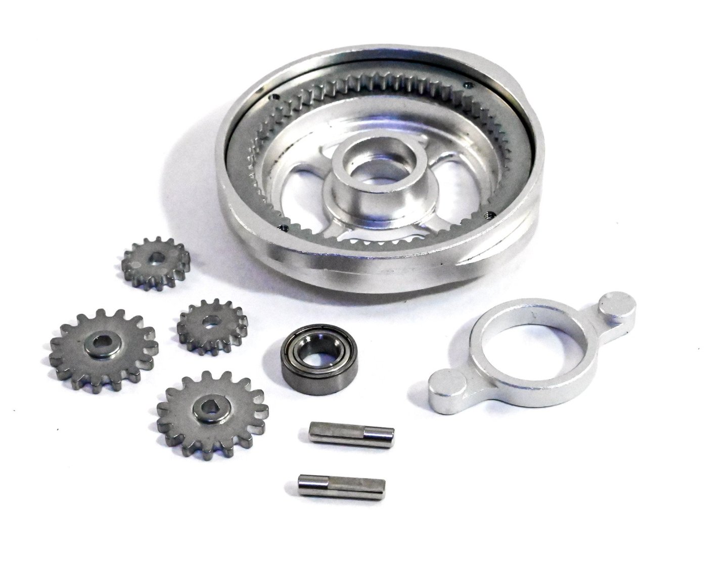
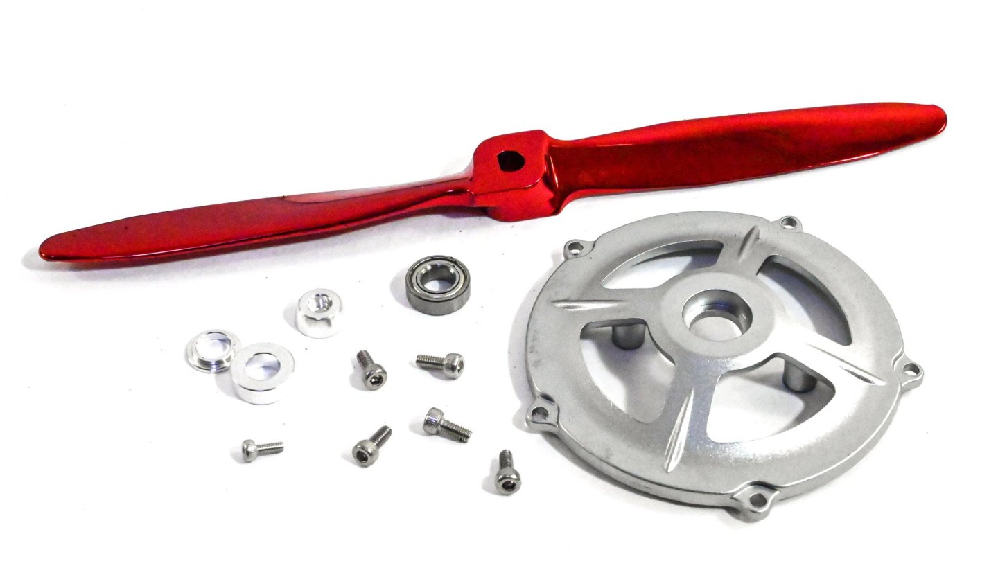
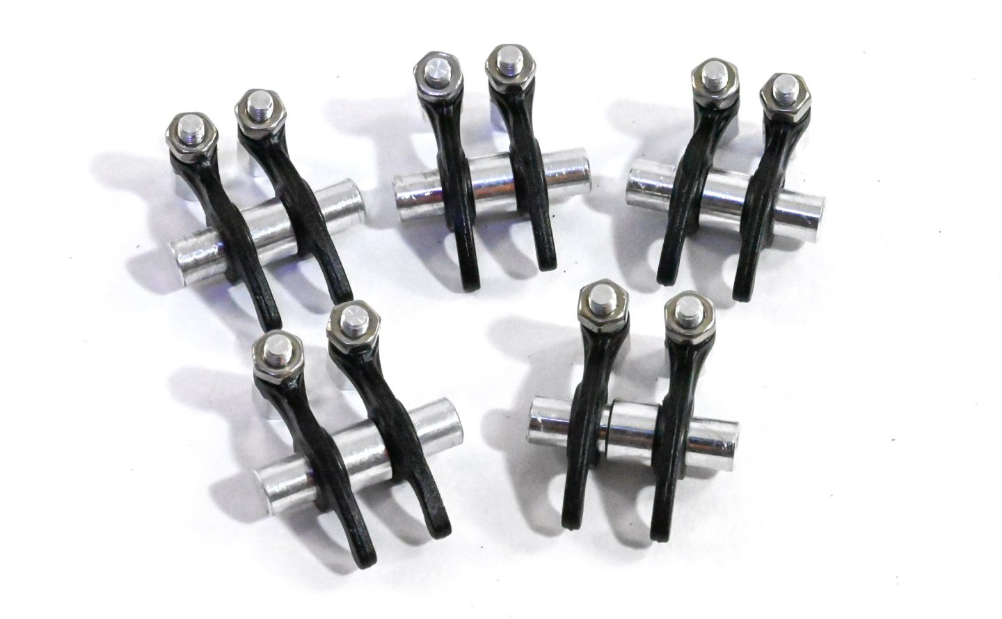
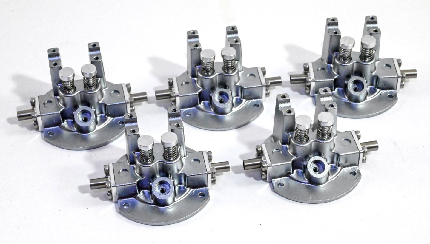
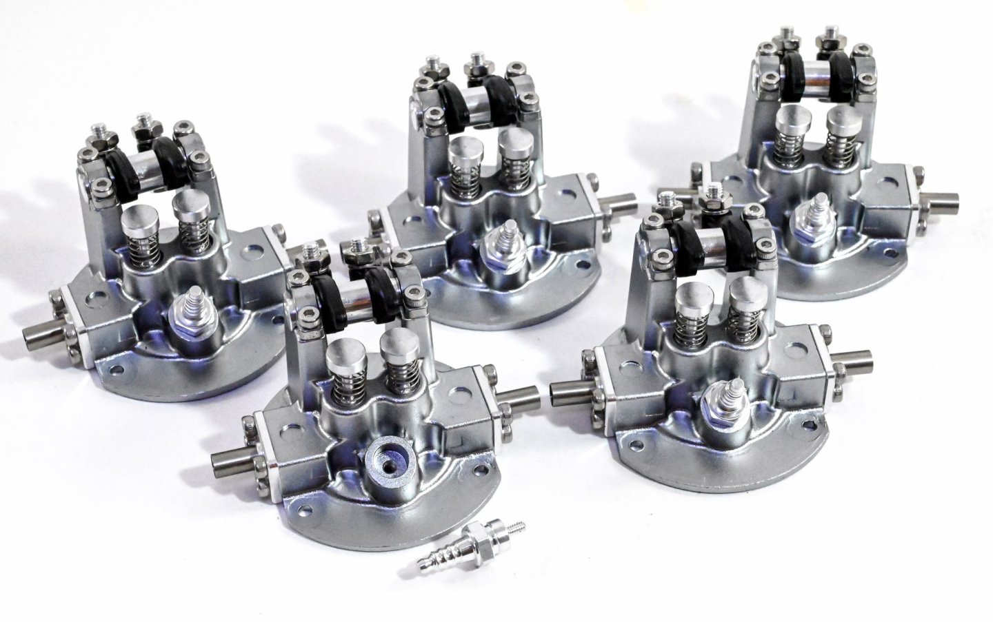
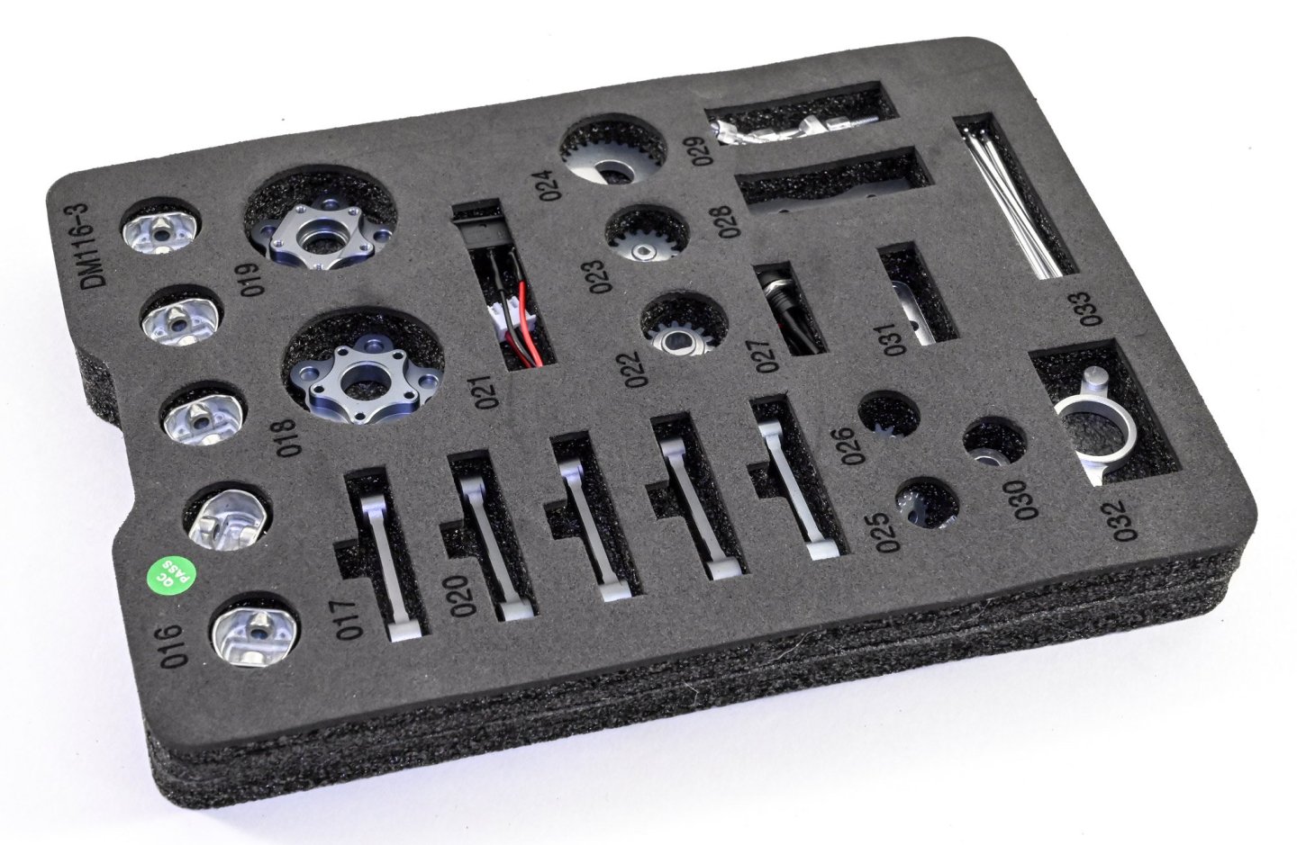
If you see any black flecks as are visible here, these are just some debris from the foam trays. Parts with this are just blown clear before assembly. Here are the cam and gear which are simply fastened with four small screws. The cam drive gears are now selected and assembled as shown. You'll notice the mounting pins are machined to accept the gears. The gears must also be fitted in the orientation shown in the manual. Yes, you see that correctly....a metallic red prop! Whilst I understand that it's better to include a machined metal prop as there won't be any balance issues, I might well have selected a different colour to anodise it. Still, this is a display model and it does looks strangely attractive when fitted. Here you see the prop and the front crankcase with the bearing, collar and prop hub parts. Now it's onto the rocker arm assemblies. It's here you'll find the only plastic parts of the engine, seen here in black. The quality is still excellent and these parts aren't at all fragile. We turn our attention to the five cylinder head assemblies. Lots of screws to use here and you can see the exhaust ports and valves here. The valves do actually work too. The rocker arms are now fitted to the top of the valve assemblies, and little reproduction spark plugs added. You could choose to paint the insulators in white, but I opted to leave in natural metal. The cylinder blocks themselves are now fitted to the completed cylinder heads.


-
kit review 5 Cylinder Radial Engine (TECHING) - EngineDIY
James H replied to James H's topic in Non ship-related reviews
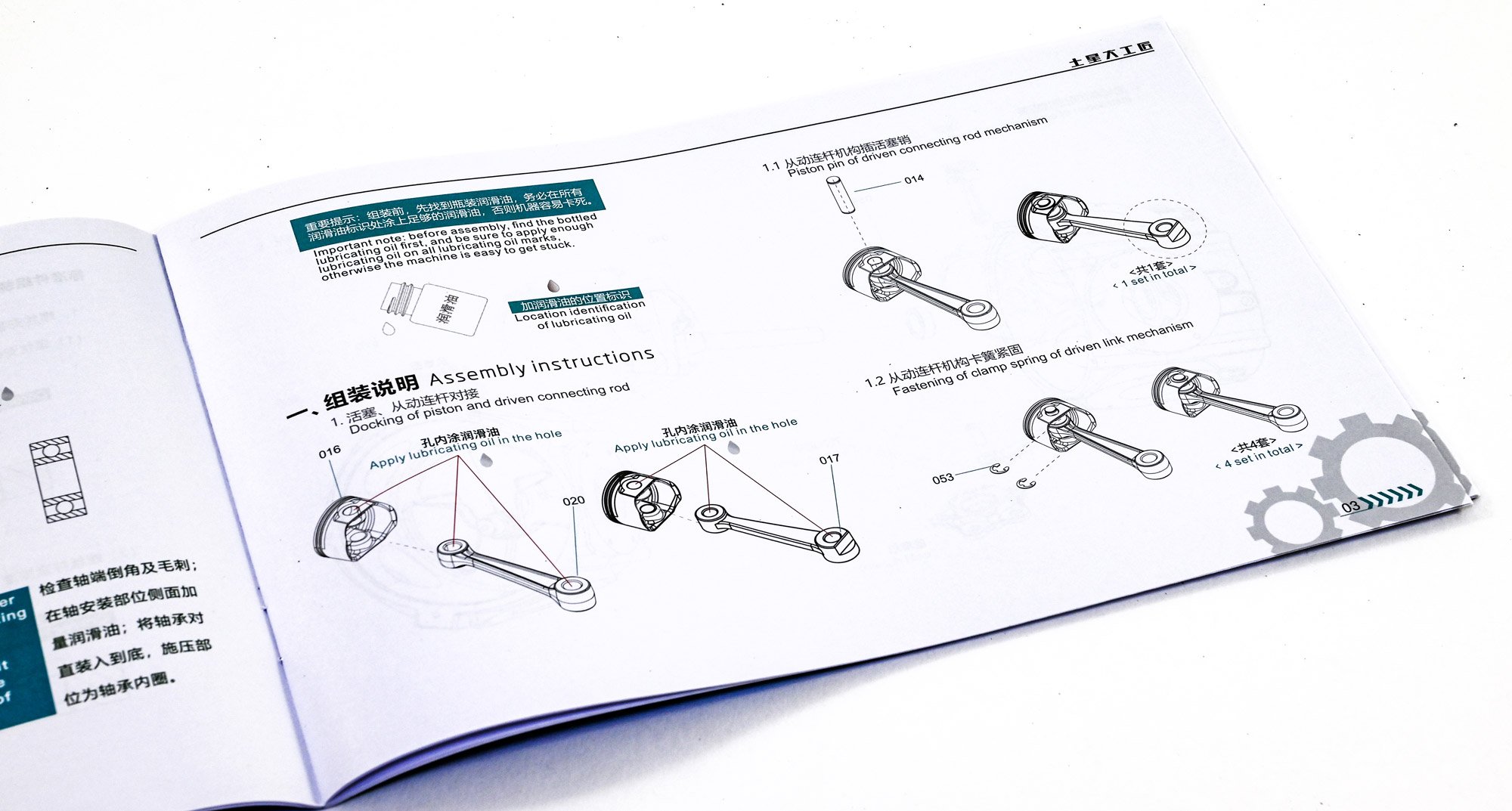
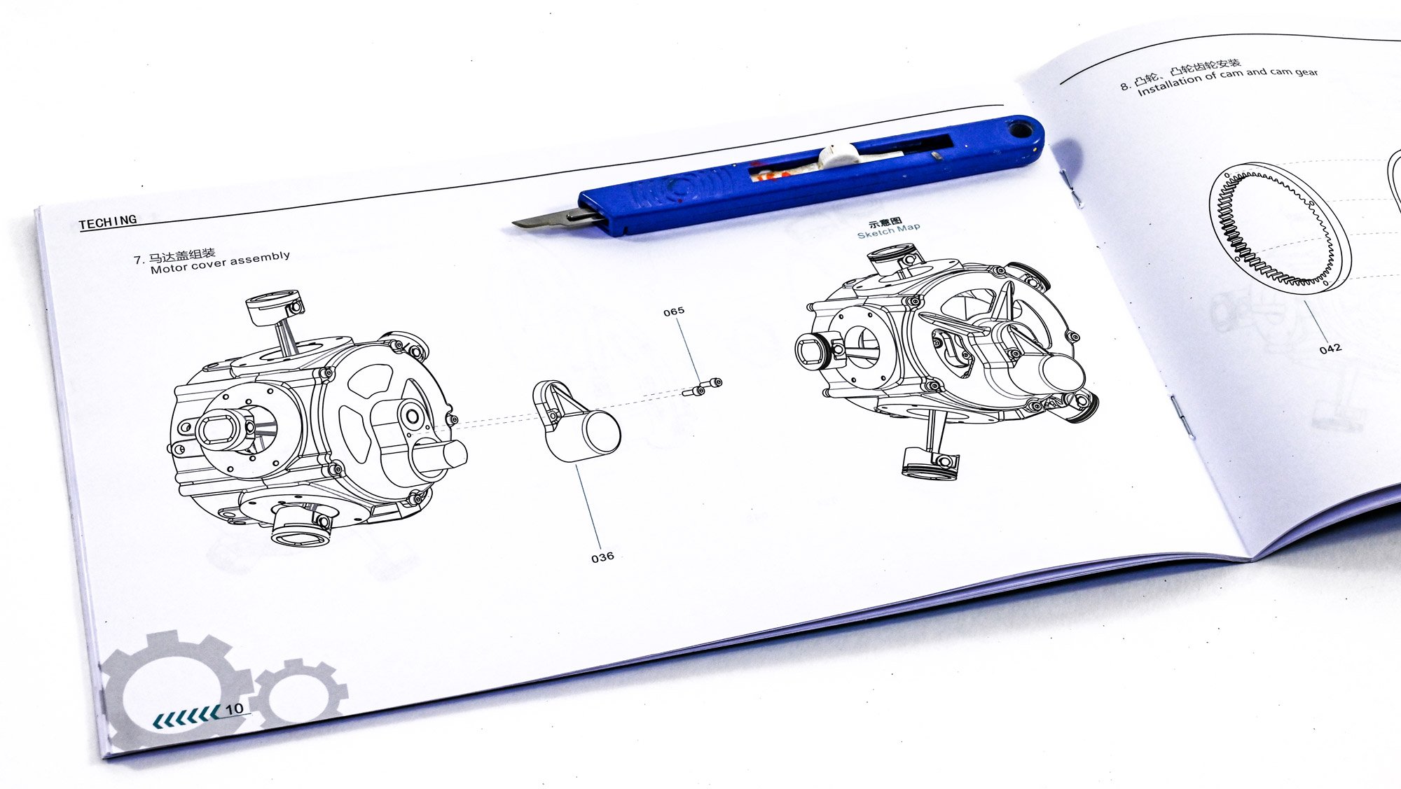
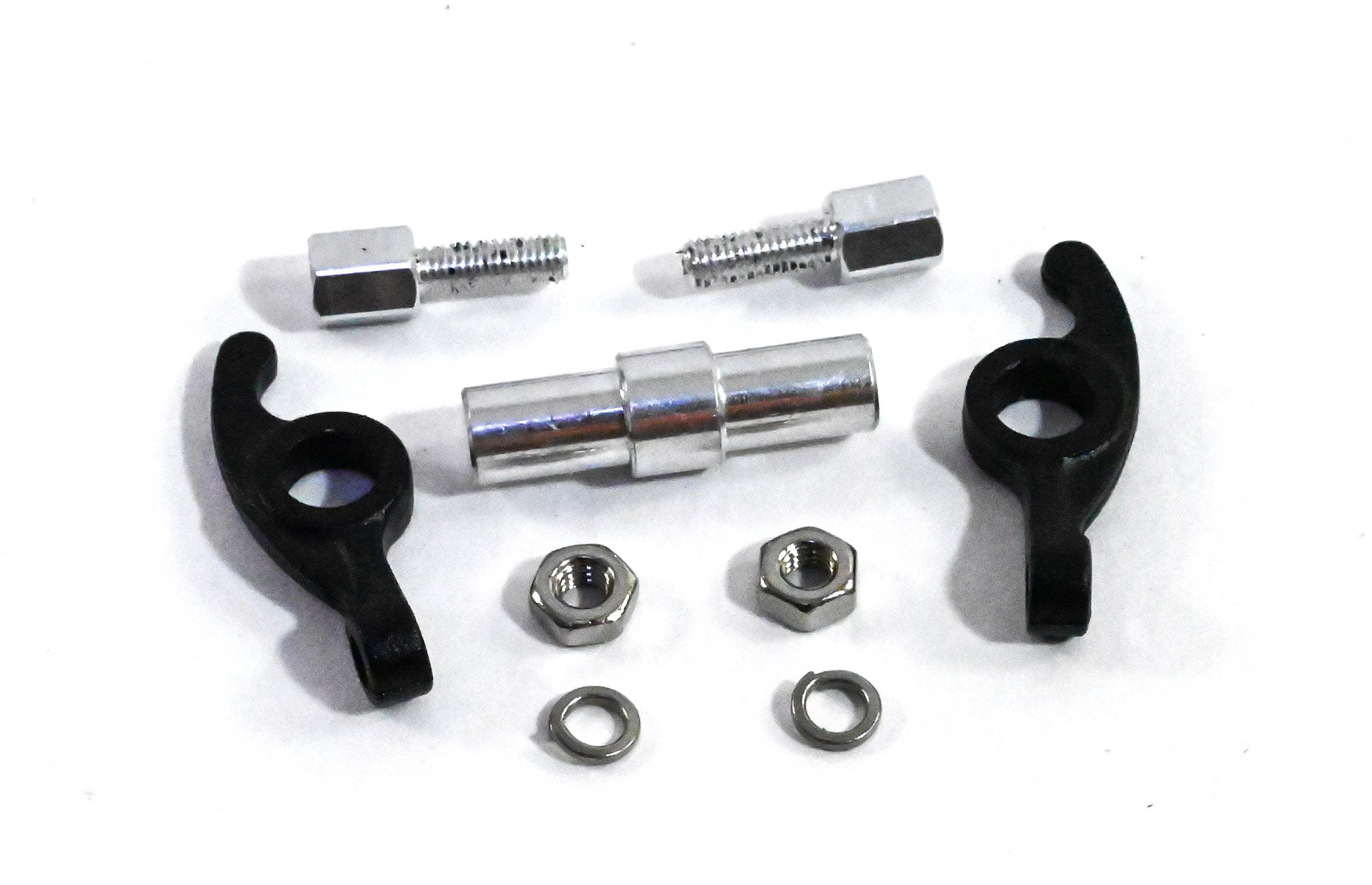
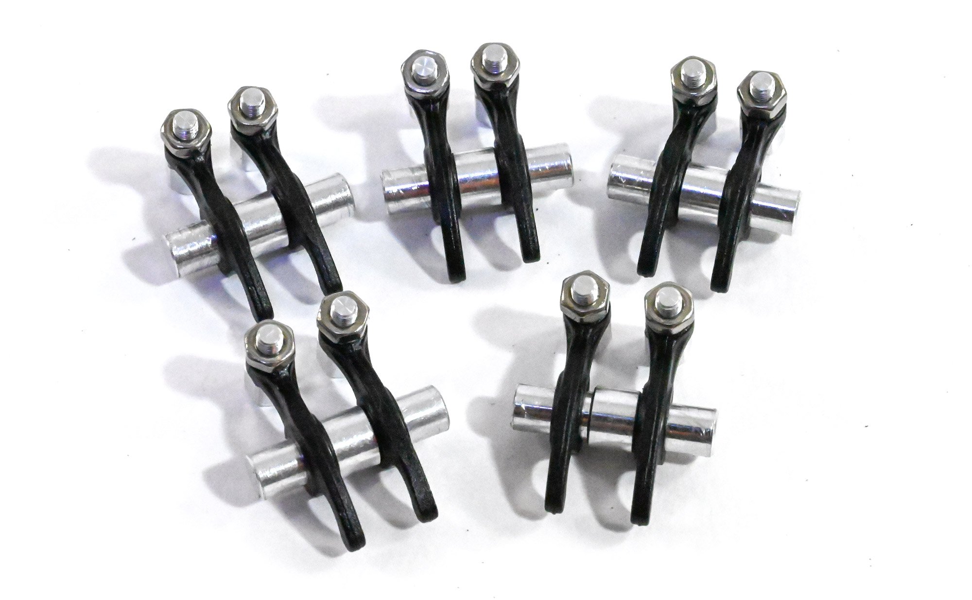
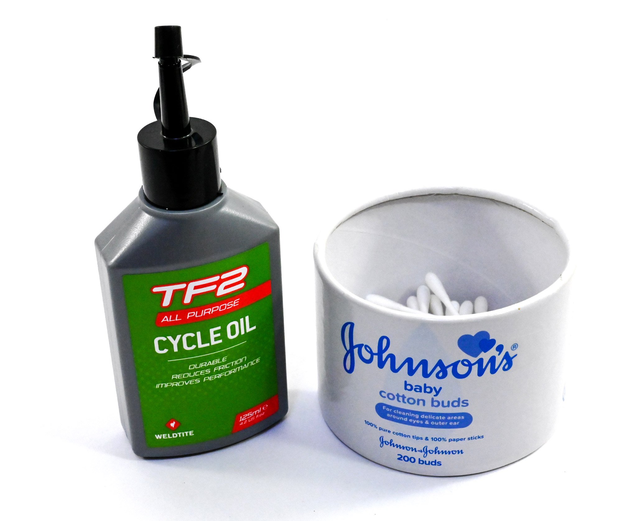
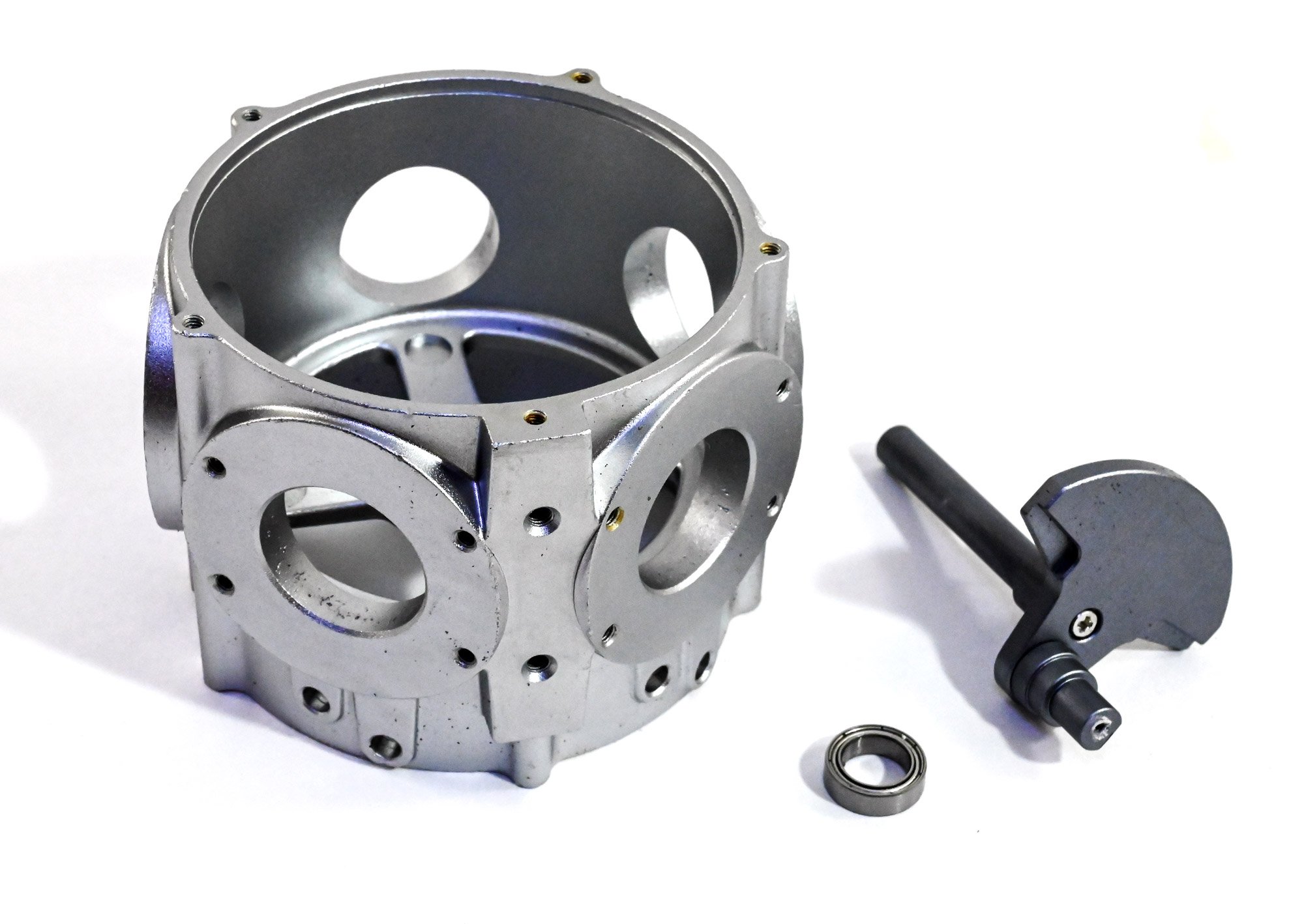
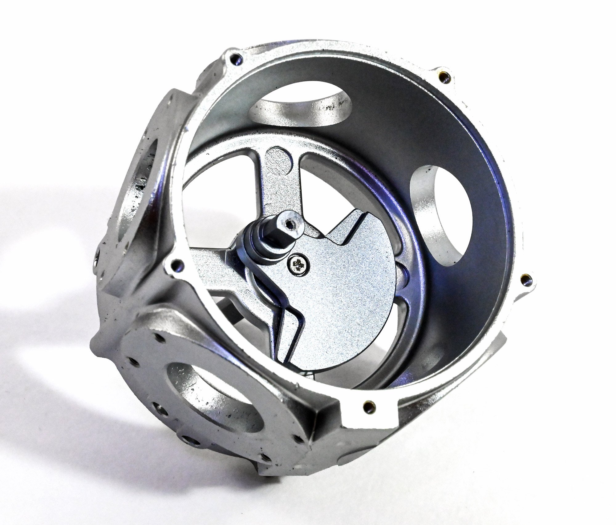
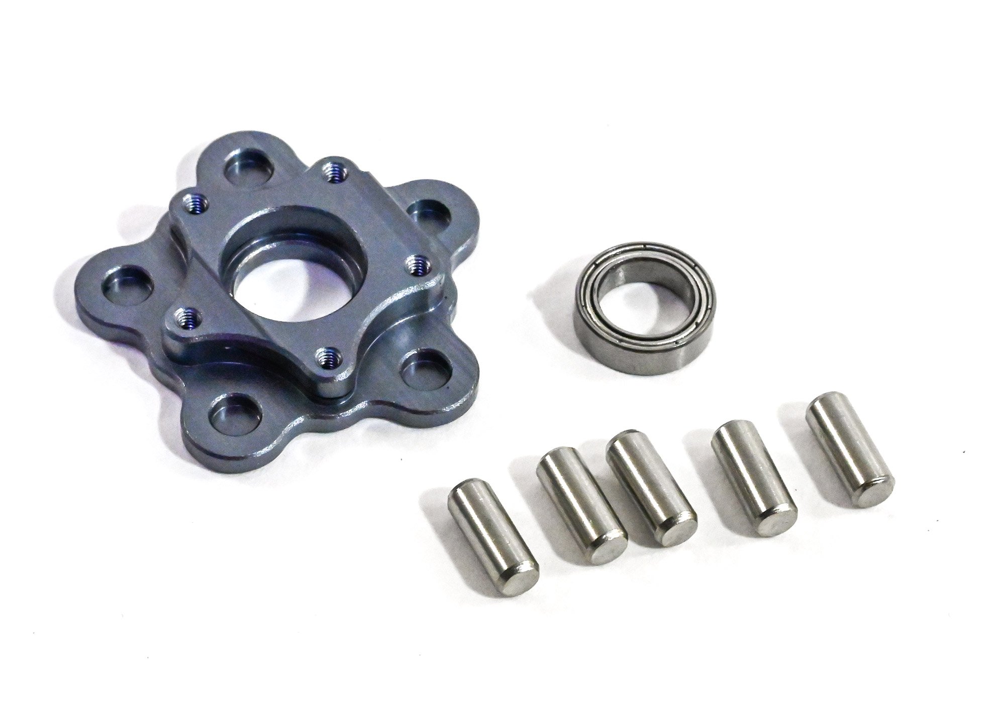
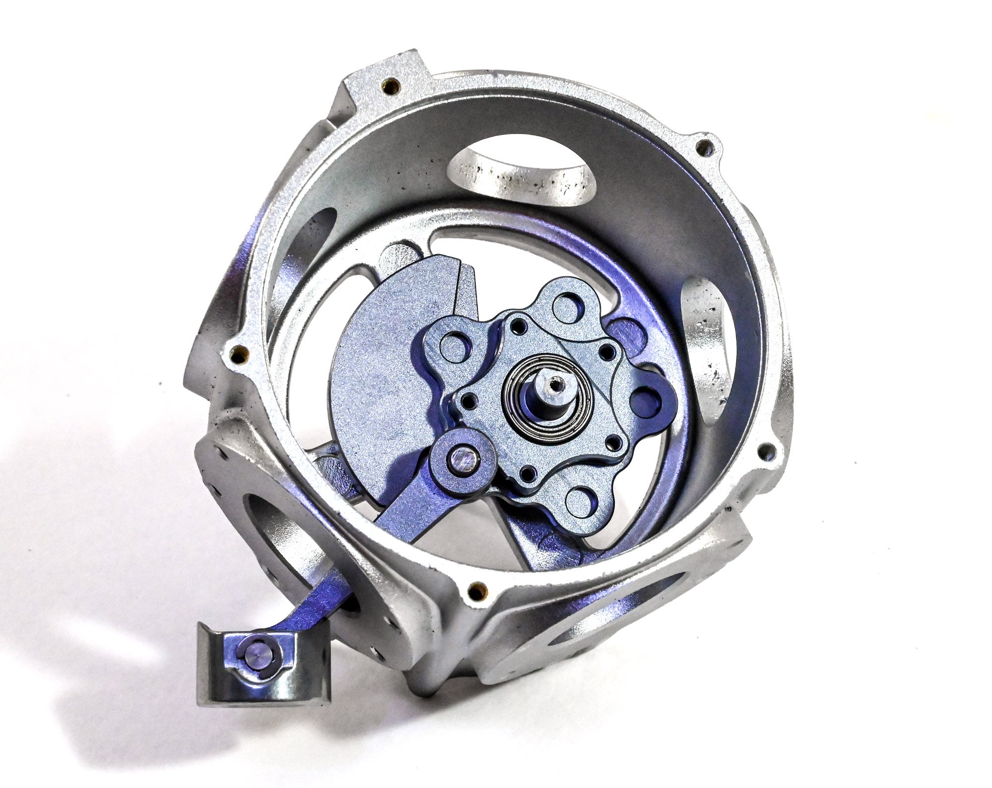
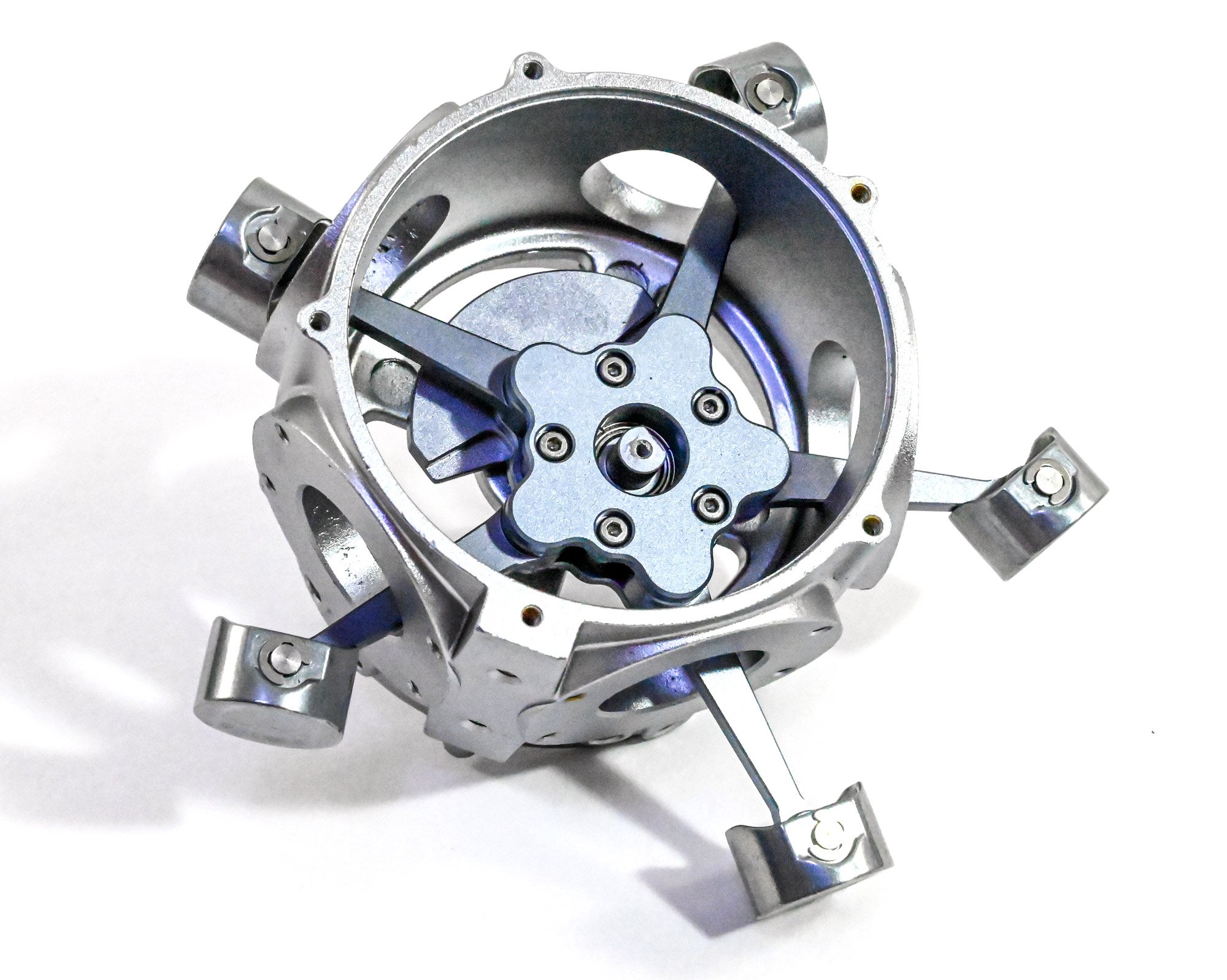
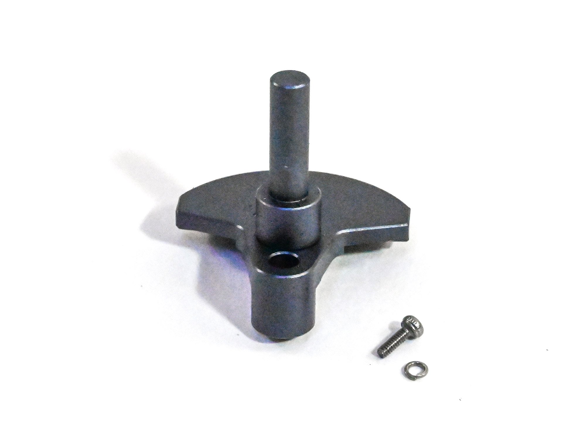
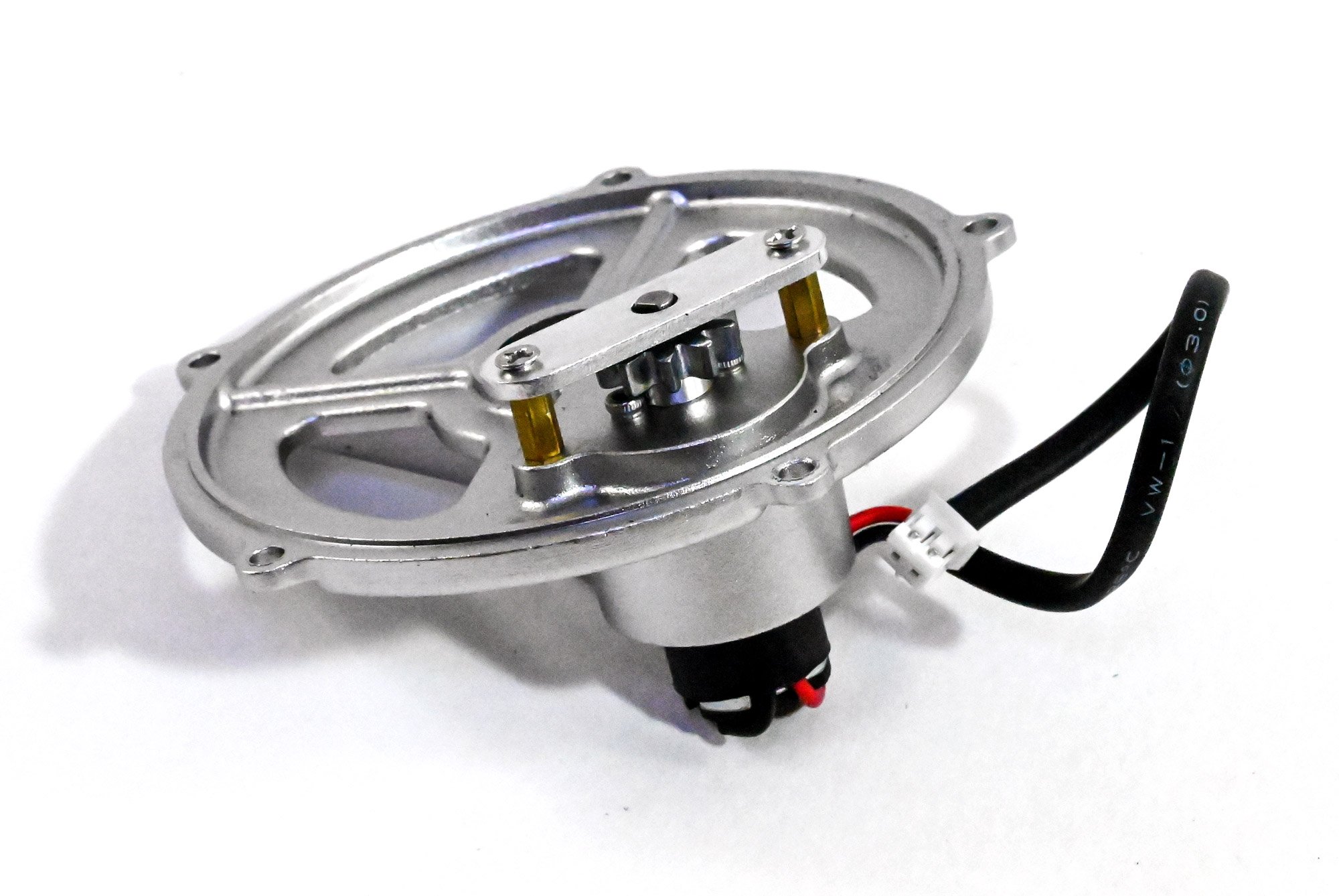
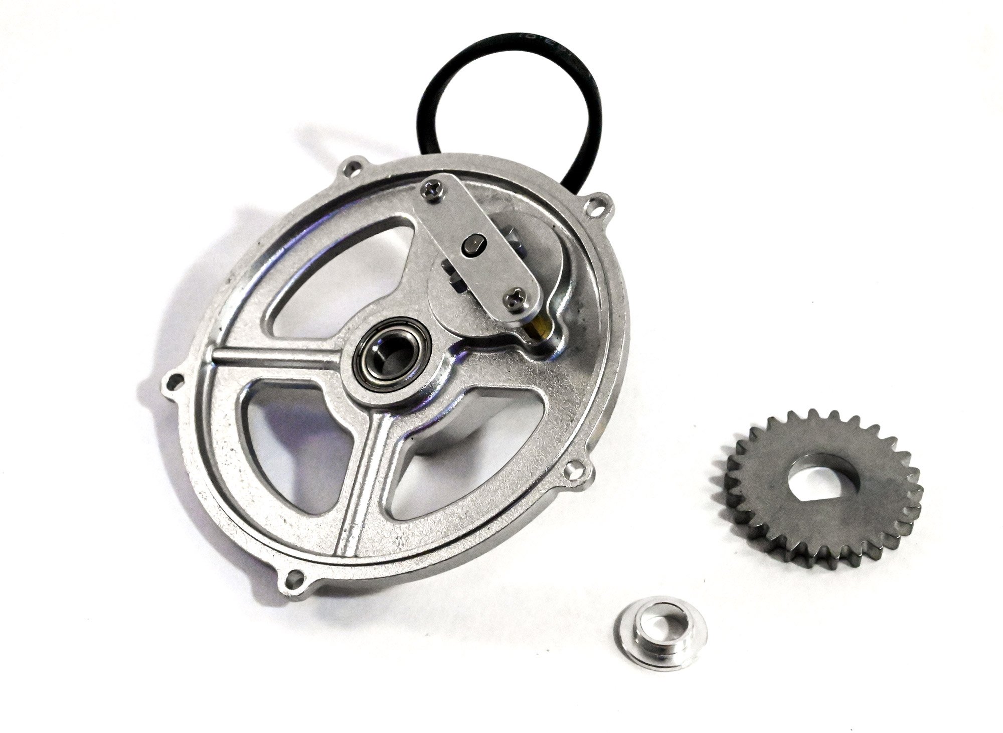
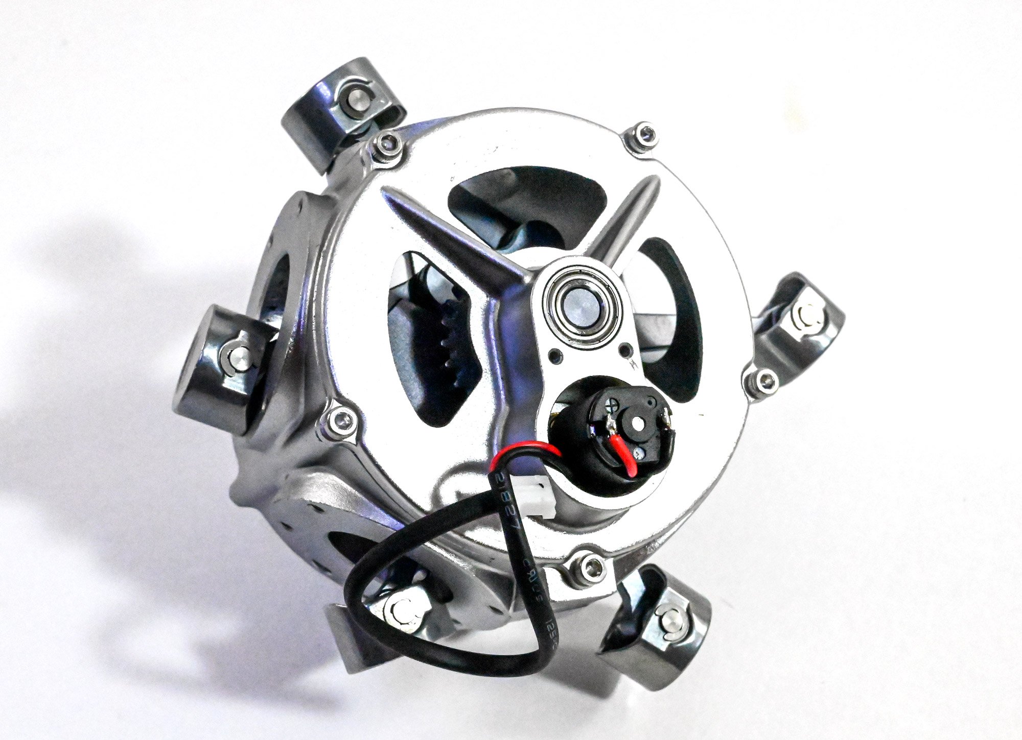
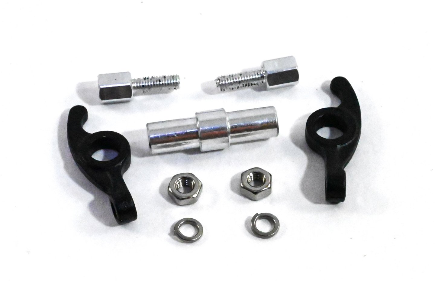
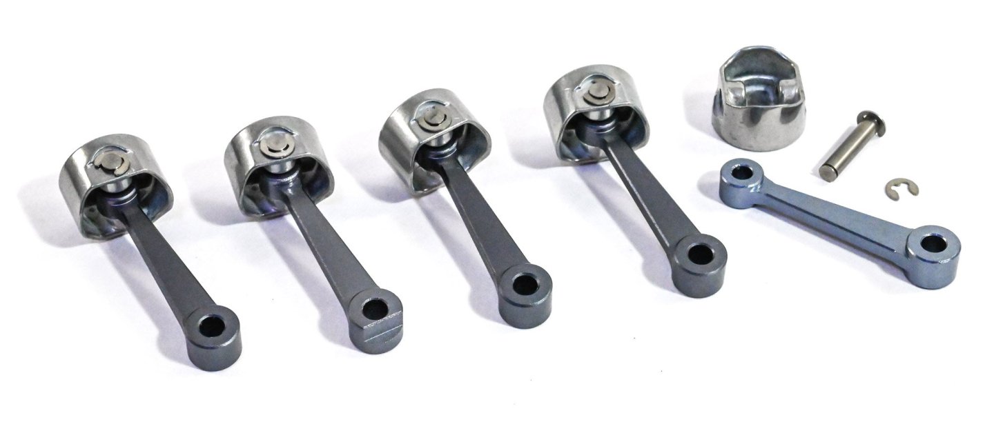
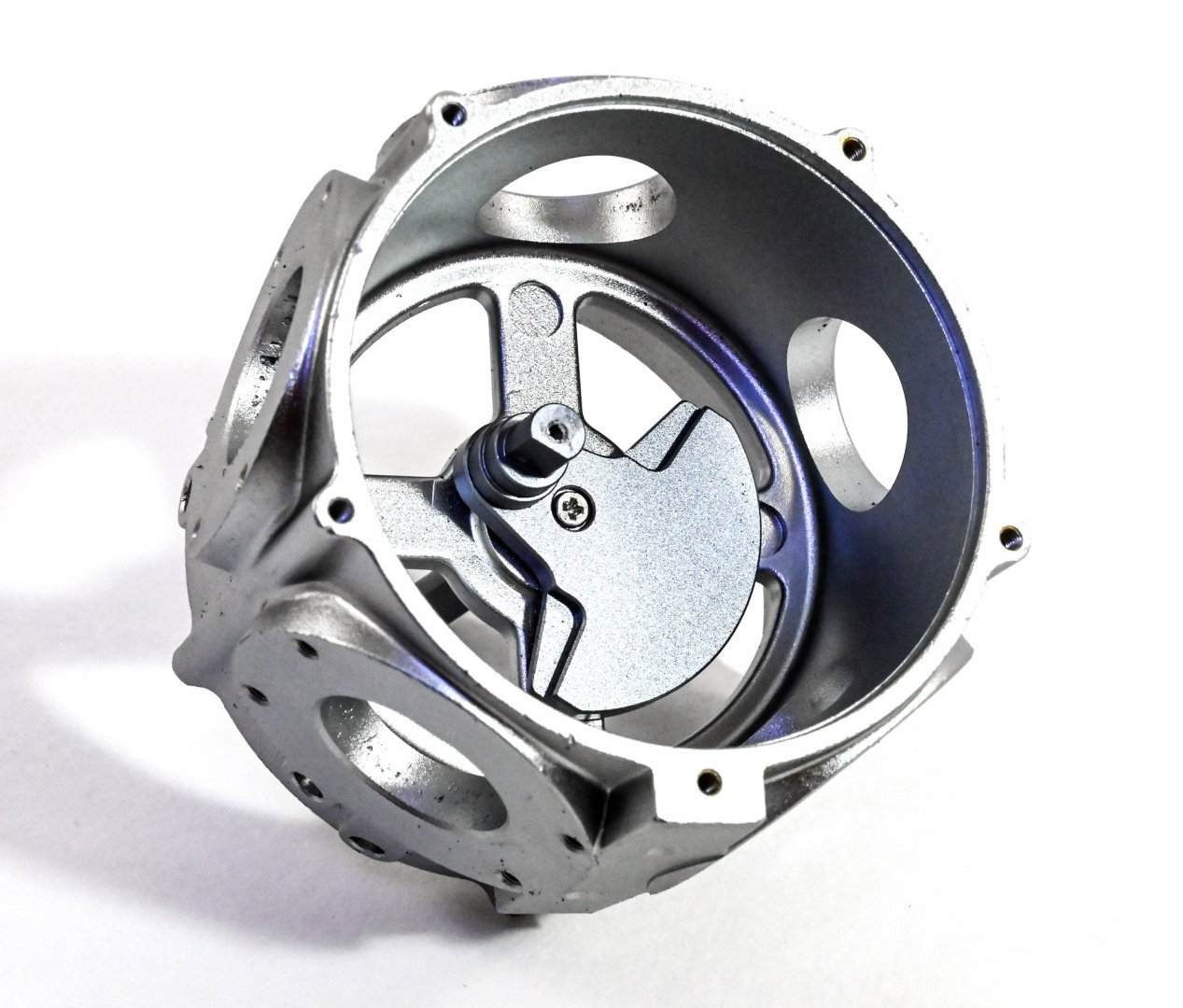
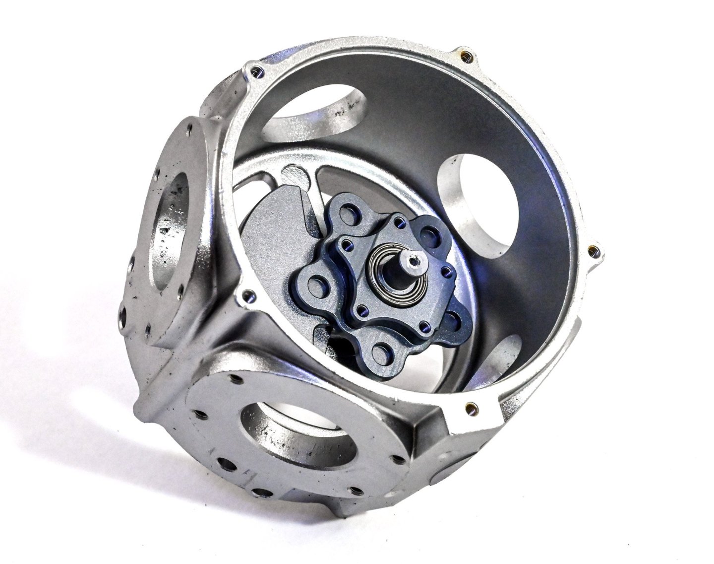
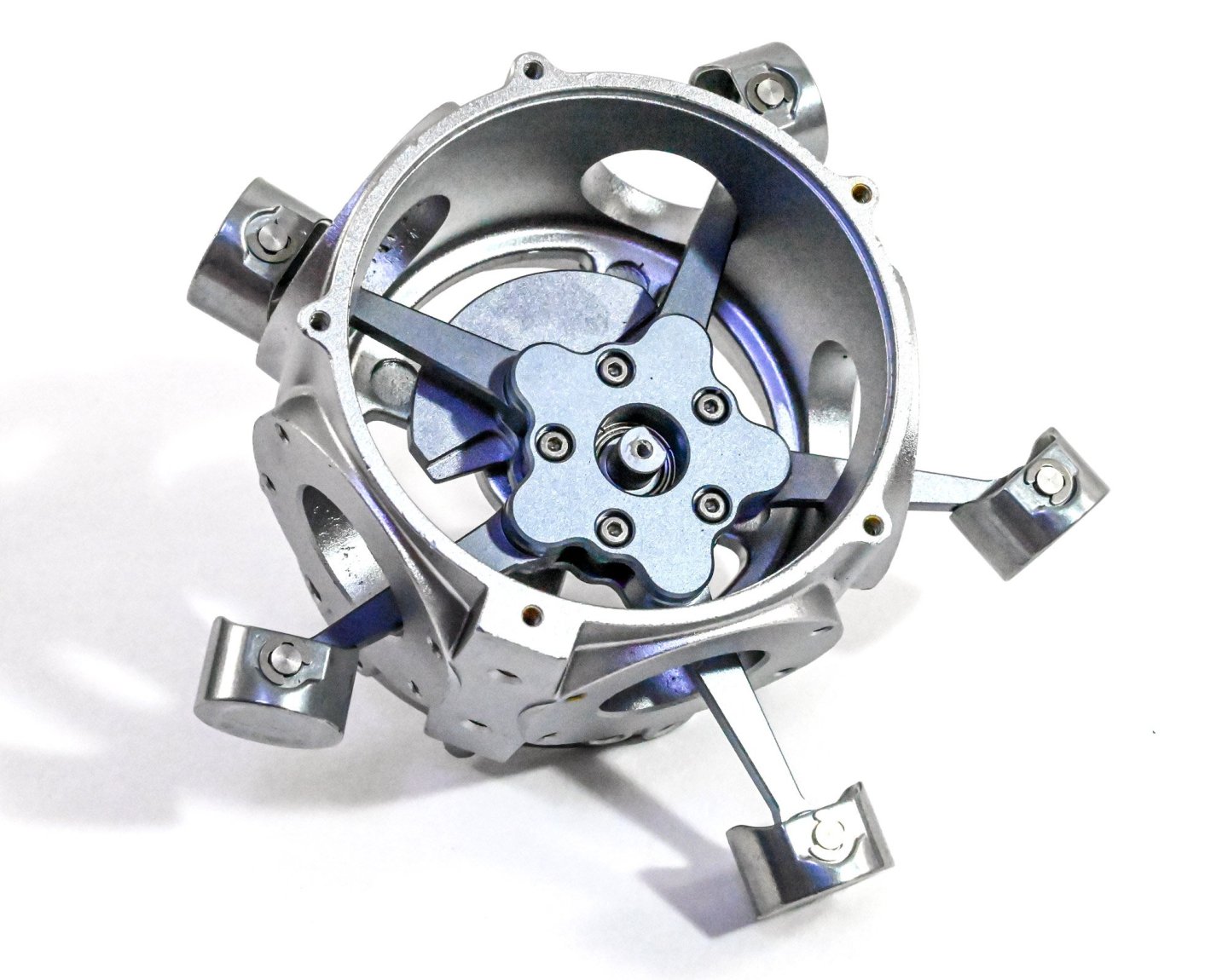
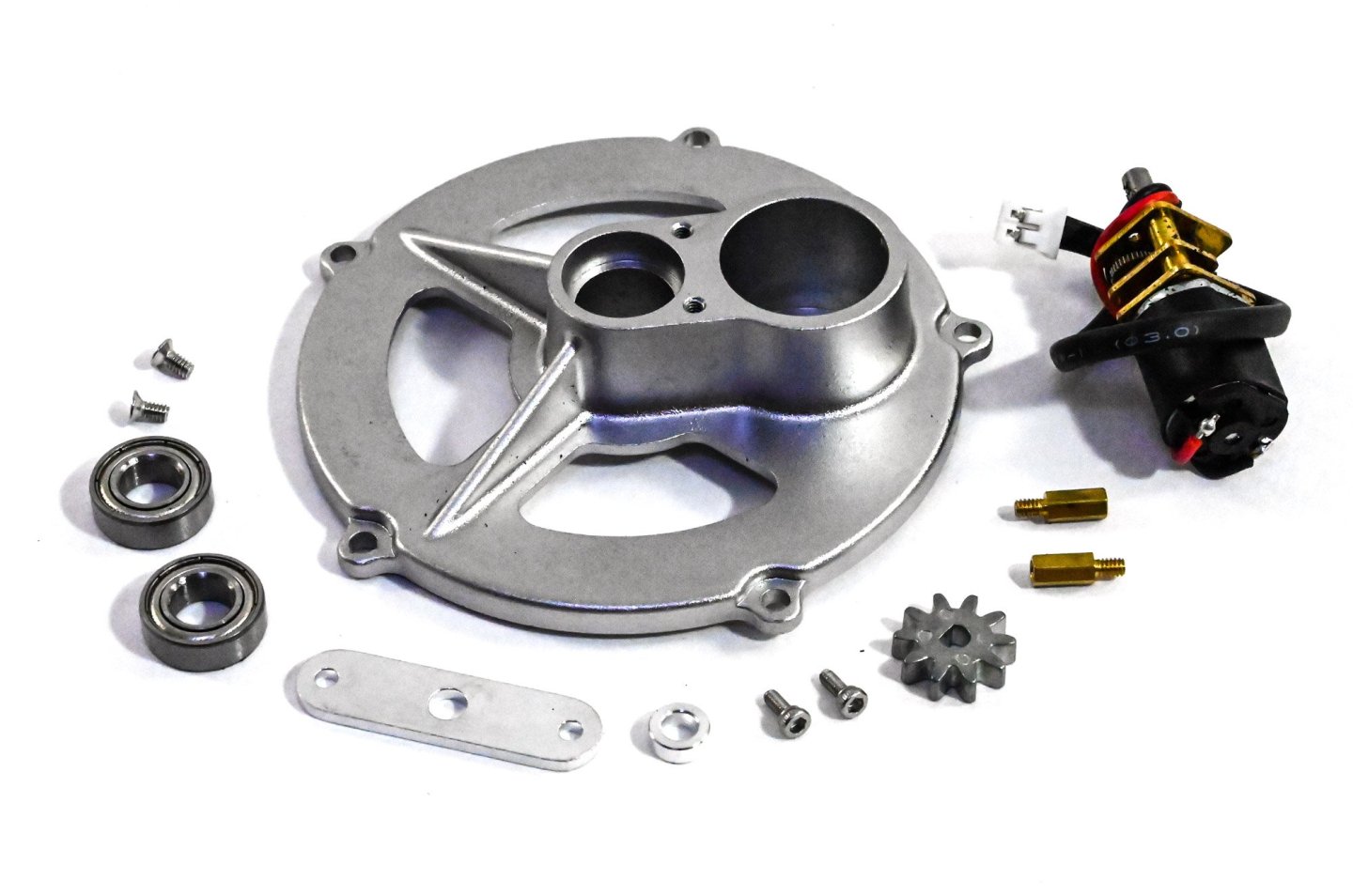
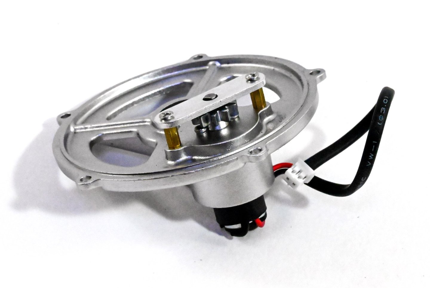
The lack of lube in the kit meant that I needed to buy some. I opted for this stuff, and used cotton buds to apply to the various connections. The manual us very clear about where lube is to be added, and this generally centres around the pistons and crankcase...not inside the piston heads. Piston assembly is very easy. All you need to do is to sit the linkages into the piston head and then insert a pin which is then locked into place by two circlips. As with the real engine, one of these has a master rod which connects to the crankshaft and does NOT articulate. Here, that is the second from the left. You can see a section machined out of the base which then is pinned to the crankshaft. The others will articulate. The crankshaft now sits within the crankcase. I add a little lube to this. This part is then added to the crankshaft and provides the base onto which the pistons will fit. This is supplied with a small bearing that neatly pushes into it before assembly. The pins you see are for locating the pistons into the recesses in the assembly. There is one task in assembling this engine, that could drive you to distraction, and that's adding the pistons. Without a doubt, this is awkward as there are five of these which will persistently try to fall out as you add the next. The best way to do this is to sit the crankcase into one of the cutouts in the foam parts tray and then carefully prop up each of the piston heads so they don't fall away from the centre of the crankcase. When you have them all in position, you can then add the linkage cap and screw it into position. This stage feels like a real achievement. This crank can now be fitted into place. This is a working model, so a little cheat needs to be fitted, in the shape of an electric motor which will drive the gearing. This is also very nicely hidden when complete. The completed rear crankcase now now be screwed to the main casing. One thing the manual does not make clear is that the motor needs to be adjacent to the stand connection on the main crankcase. I did fathom that out, but I have seen at least one video where a builder has a wire stretched around the back of the crankcase, down to the stand which contains the battery. The motor is then covered over.


-
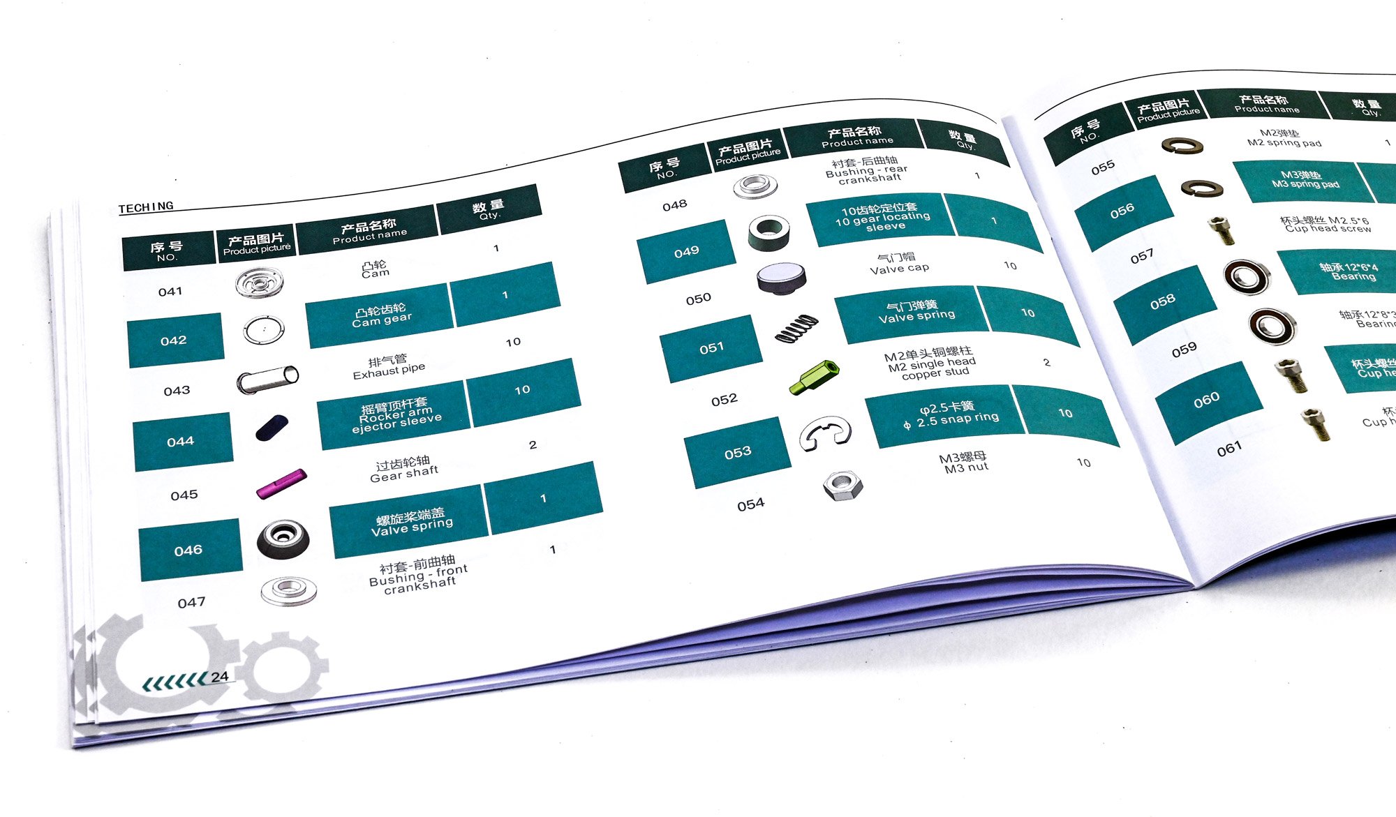
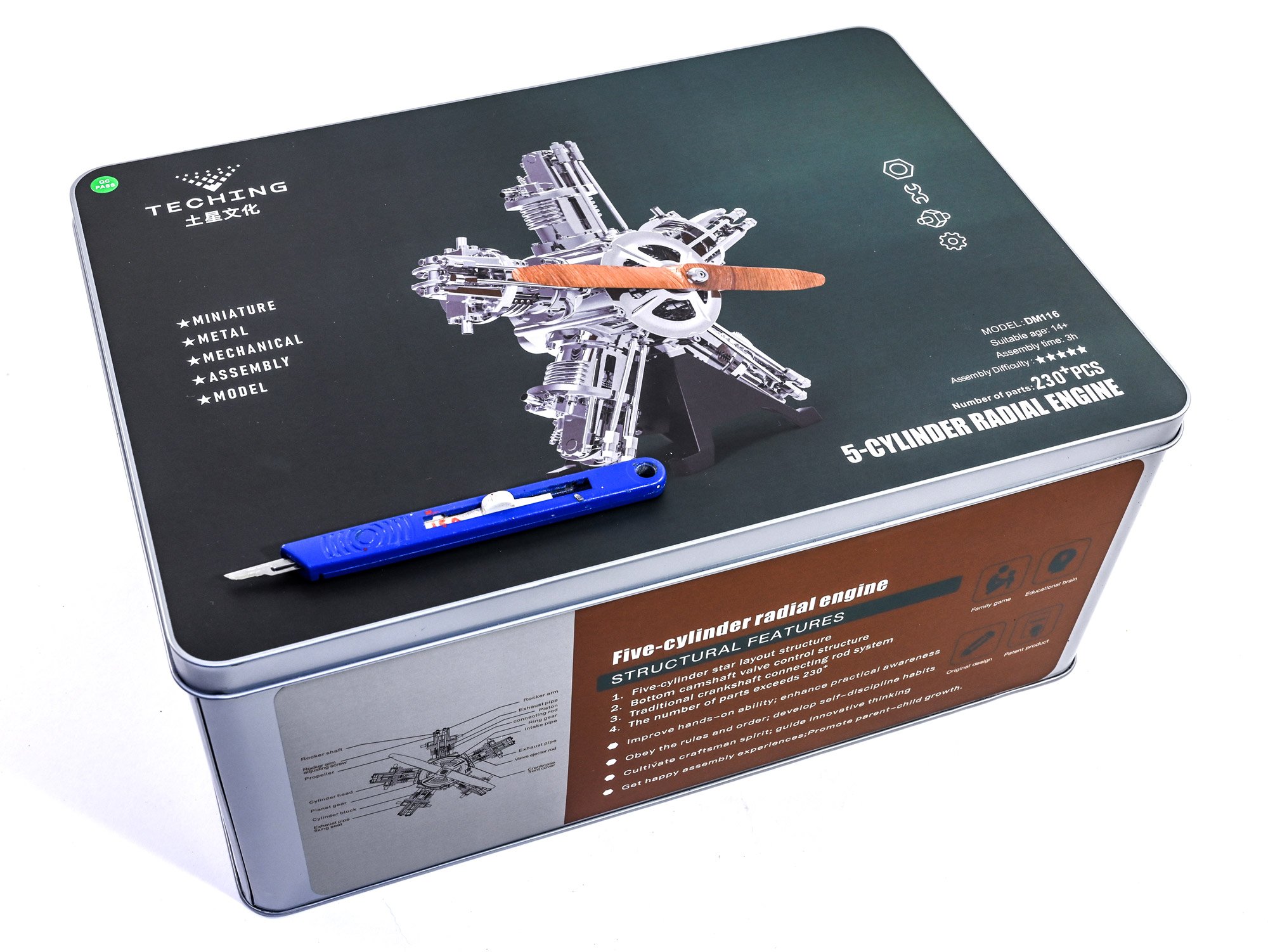
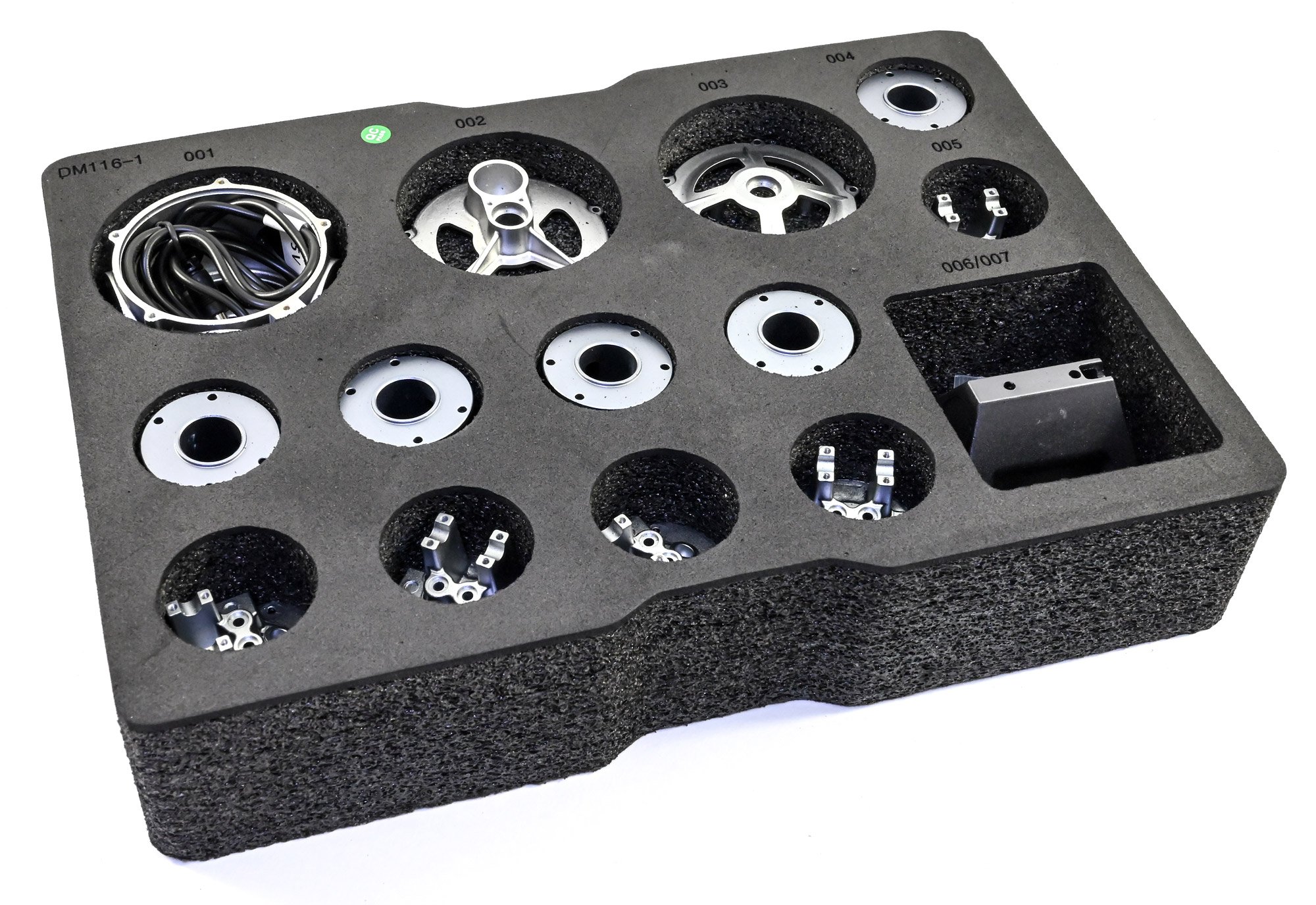
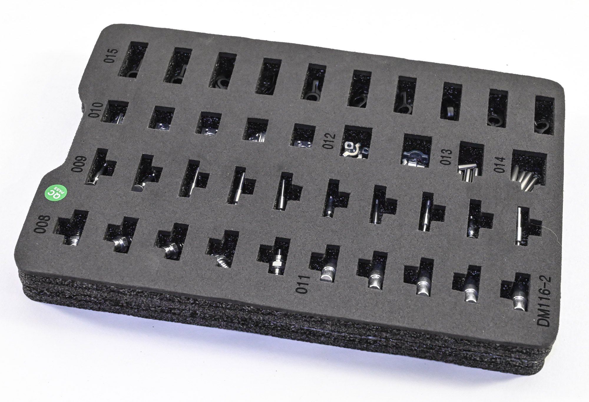
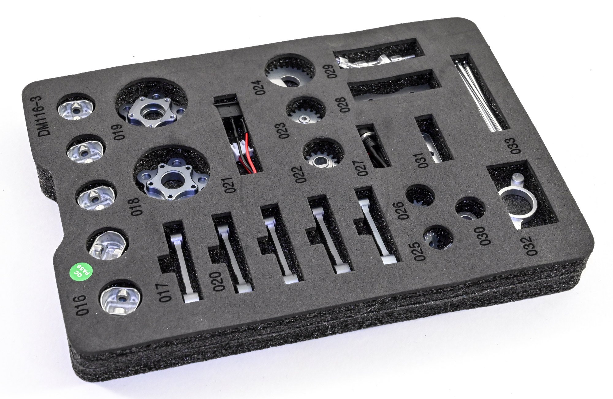
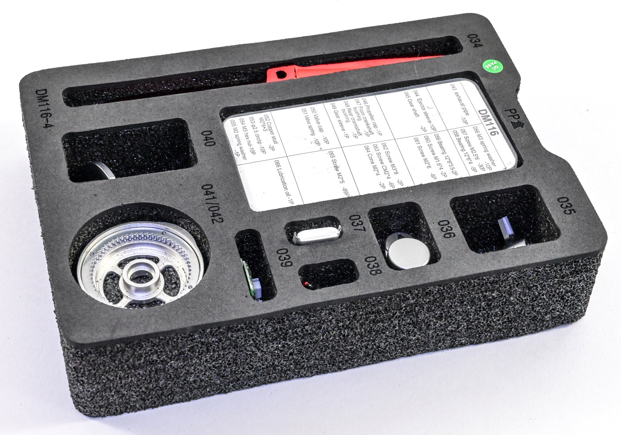
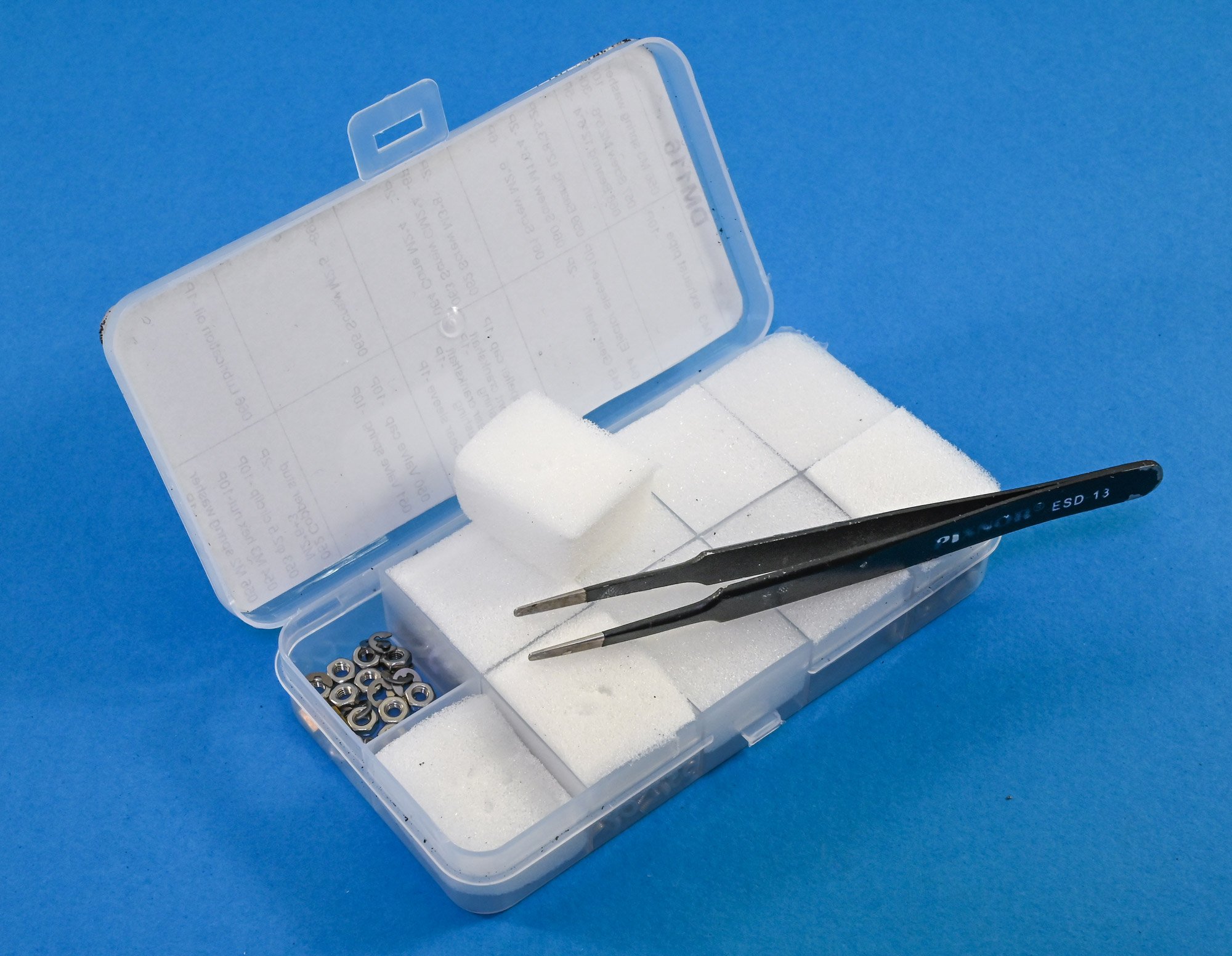
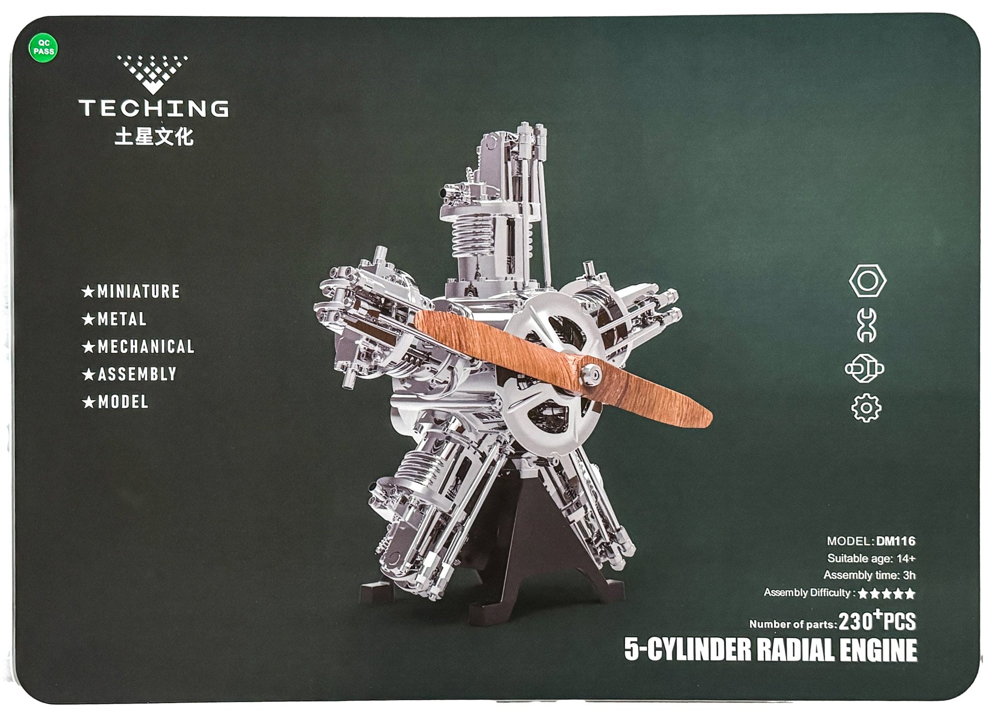
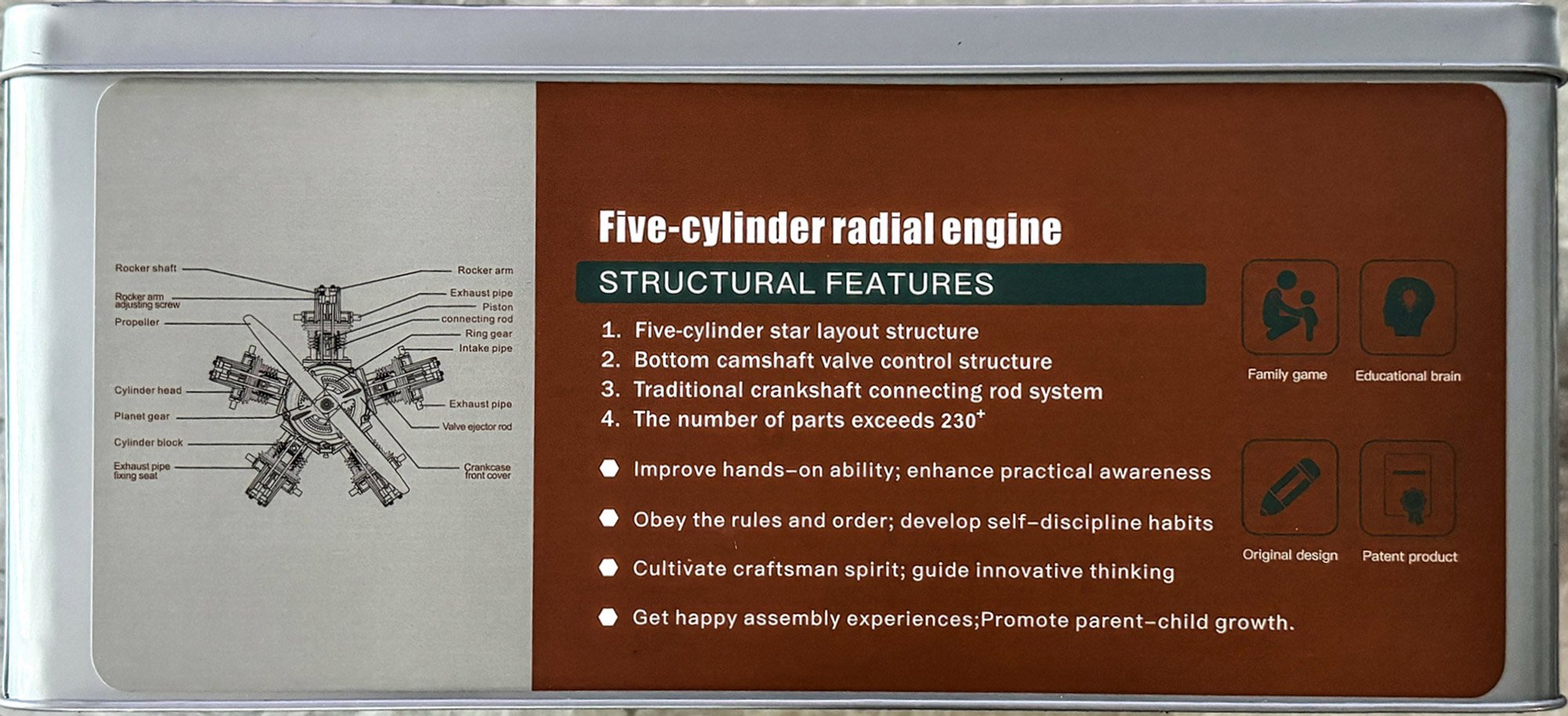
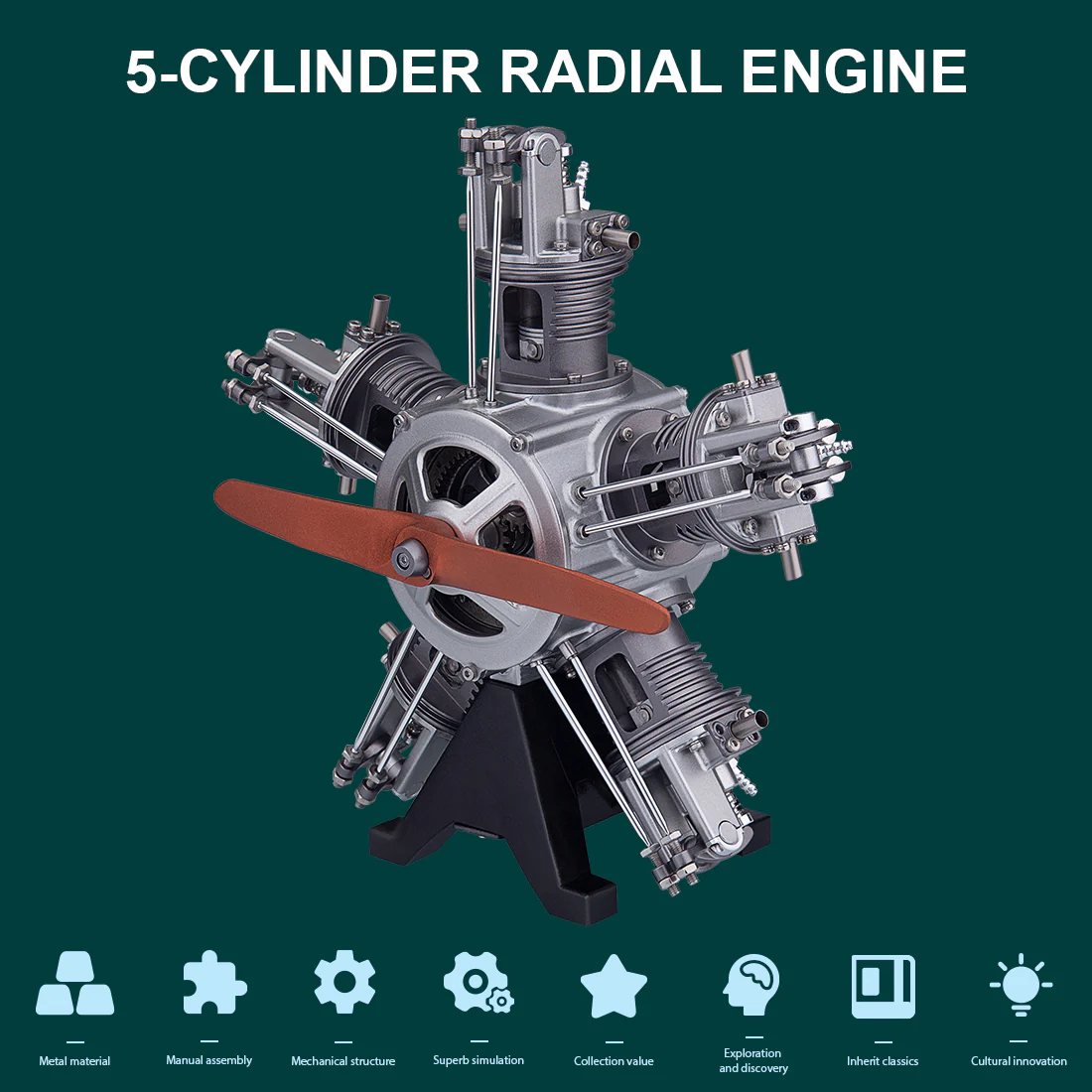
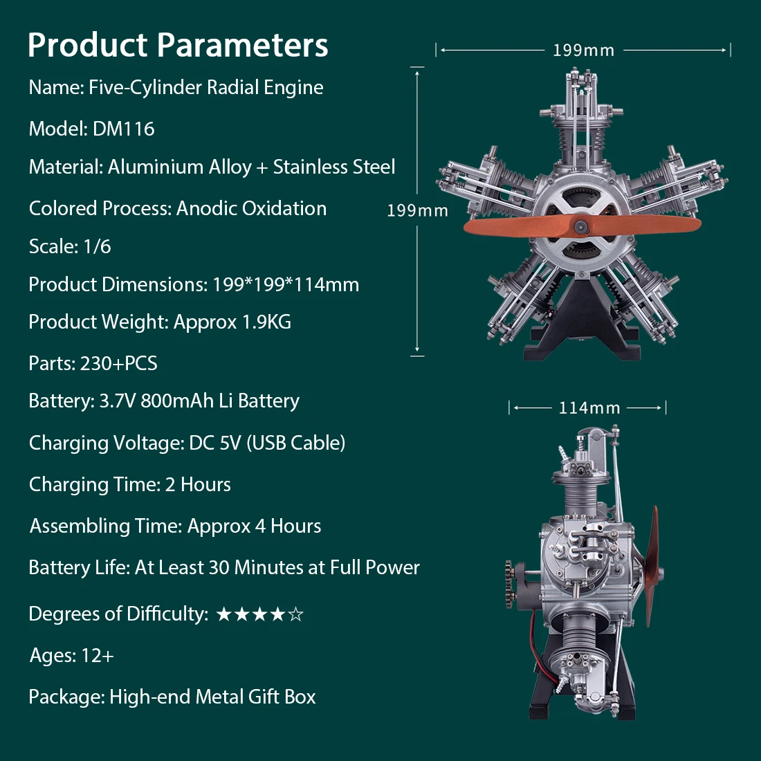
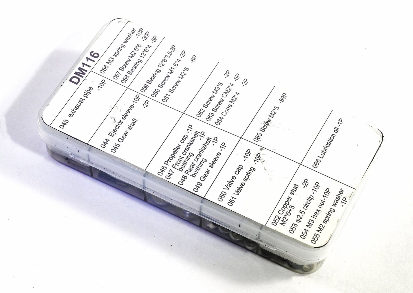
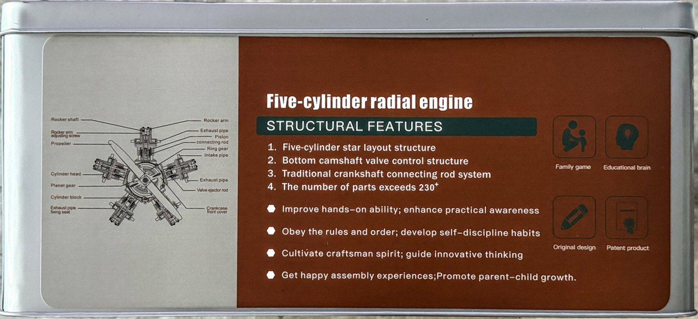
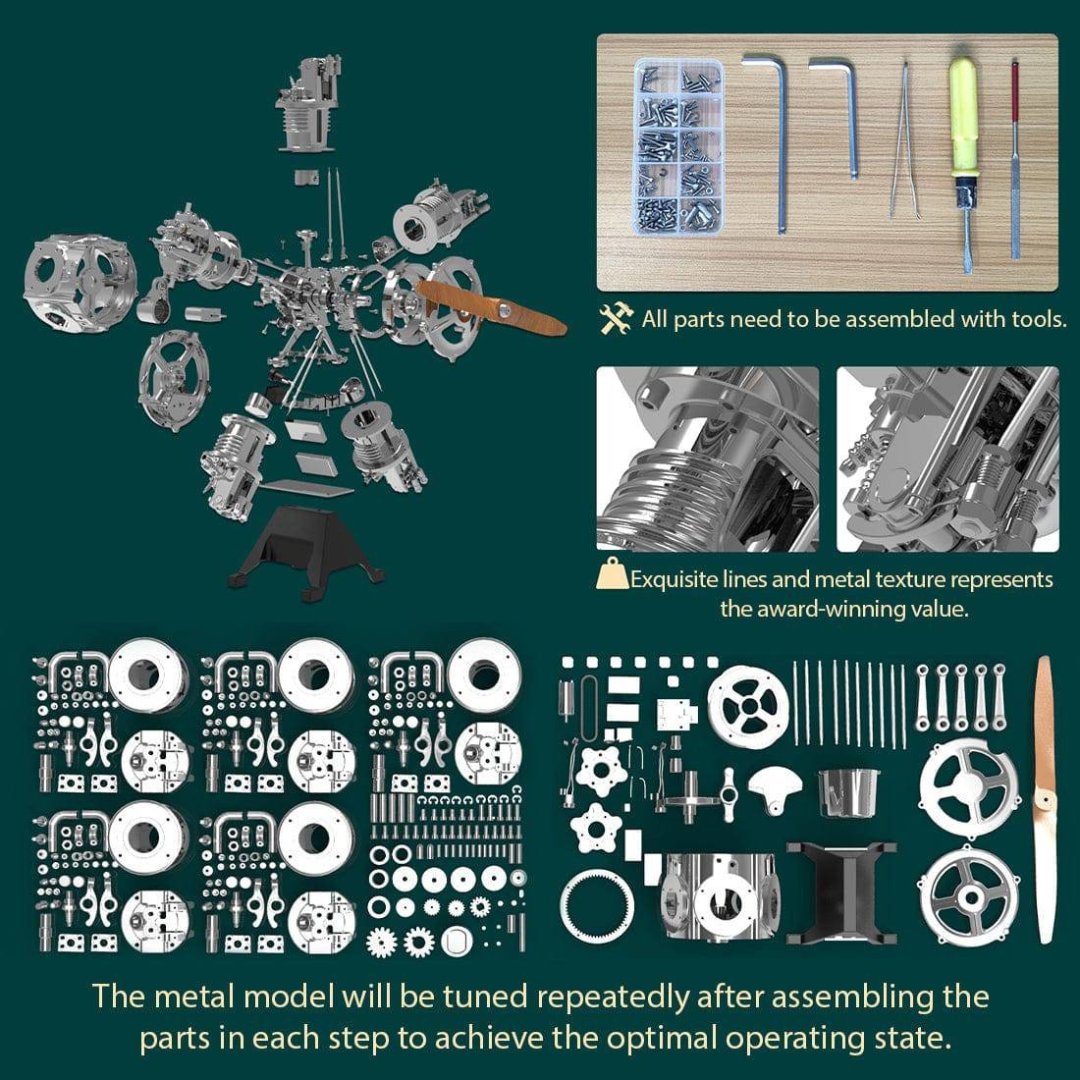
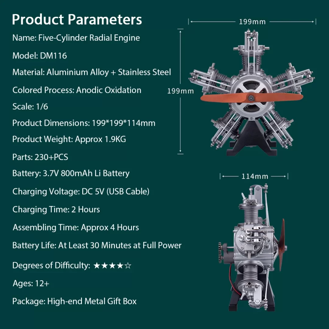
1:6 Five Cylinder Radial Engine (TECHING) EngineDIY Catalogue # 33ED3355414 Available from EngineDIY for $469.99 C. M. Manly constructed a water-cooled five-cylinder radial engine in 1901, a conversion of one of Stephen Balzer's rotary engines, for Langley's Aerodrome aircraft. Manly's engine produced 52 hp (39 kW) at 950 rpm. Most radial engines are air-cooled, but one of the most successful of the early radial engines (and the earliest "stationary" design produced for World War I combat aircraft) was the Salmson 9Z series of nine-cylinder water-cooled radial engines that were produced in large numbers. Georges Canton and Pierre Unné patented the original engine design in 1909, offering it to the Salmson company; the engine was often known as the Canton-Unné. The radial engine is a reciprocating type internal combustion engine configuration in which the cylinders"radiate" outward from a central crankcase like the spokes of a wheel. The pistons are connected to the crankshaft with a master-and-articulating-rod assembly. One piston, the uppermost one in the animation, has a master rod with a direct attachment to the crankshaft. The remaining pistons pin their connecting rods' attachments to rings around the edge of the master rod. Extra "rows" of radial cylinders can be added in order to increase the capacity of the engine without adding to its diameter. The kit A 1:6 engine comes in quite a large box, as I soon realised. Actually, it's a very high quality tin, with a lid that lifts right off to display an instruction manual sitting between two pieces of protective foam. The lid itself shows an illustration of the completed engine, while the side has the kit-specific details. For an idea of scale, I've sat my Swann Morton retractable scalpel on the kit. There's a reasonable amount of weight in this kit too...approximately between 1.5 and 2kg. No surprise as this kit is 99% metal. The side panel of the tin gives a few more details. All of the parts in this kit are recessed within sturdy foam trays that also have the part numbers engraved into the foam, adjacent to each part. This makes it ridiculously easy to find exactly what you need in each stage. There are FOUR trays of components in this kit. While there are are a number of electronics parts, with the exception of these and the plastic cylinder head rockers, everything is in cast or machined aluminium etc. You'll notice the white plastic box in that tray. That's choc-full of screws, turned parts, springs, bearings etc. Each little section is padded with some foam. Again, there's no lube in this box. It must be something they had to leave out for some reason. Quite add as the kit contains another contentious item....a lithium battery.


-
I regularly upload images that are 2000x1300+ in size. We have had this problem before and it just disappeared. I think it was 3yrs ago. @Scottish GuyDo you have a VPN? If so, were you using it? If not, please try with it on, and vice-versa.
-
test

-
kit review 1:80 Endeavour – America’s Cup 1934 - Amati
James H posted a topic in REVIEWS: Model kits
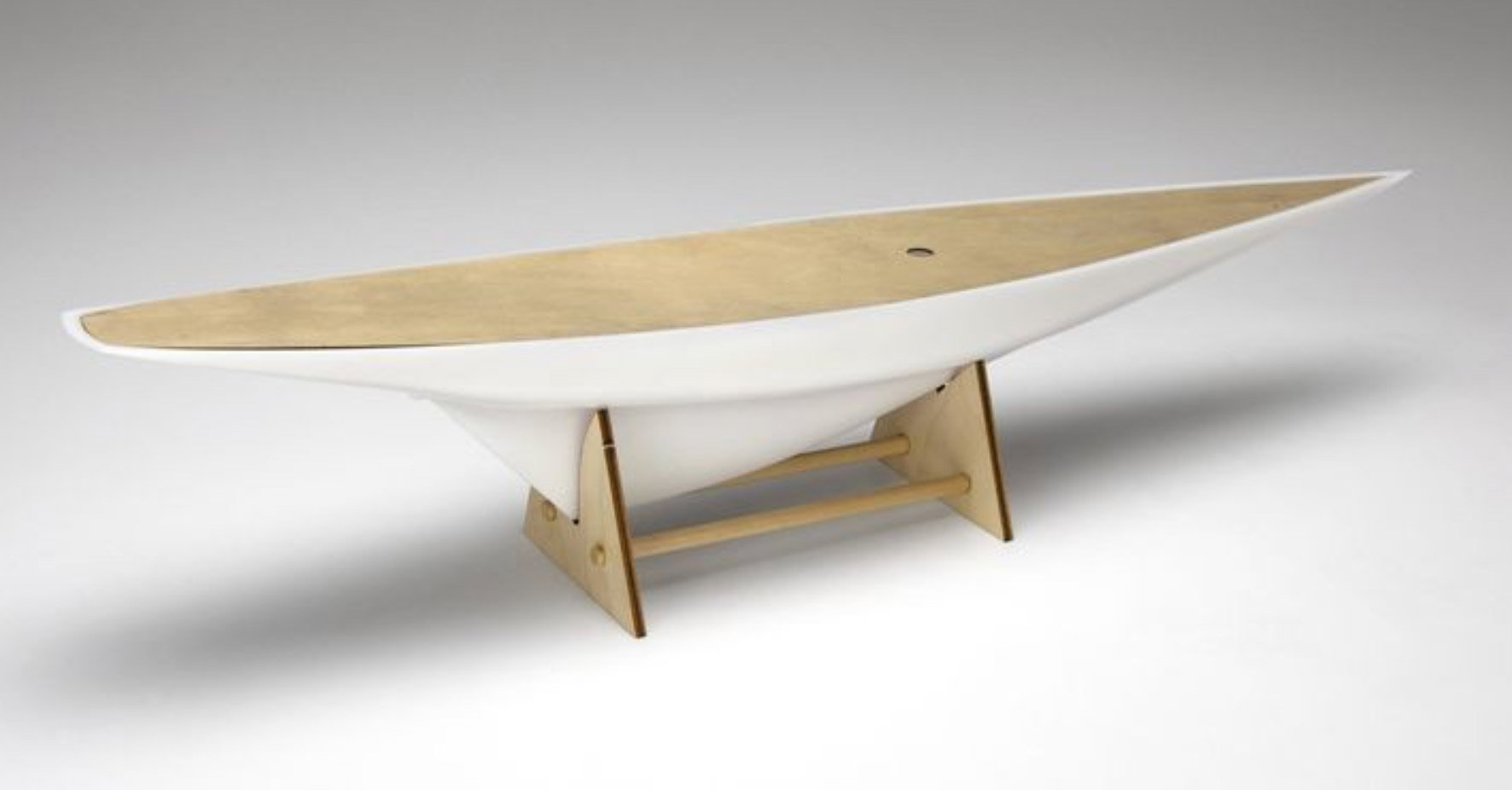
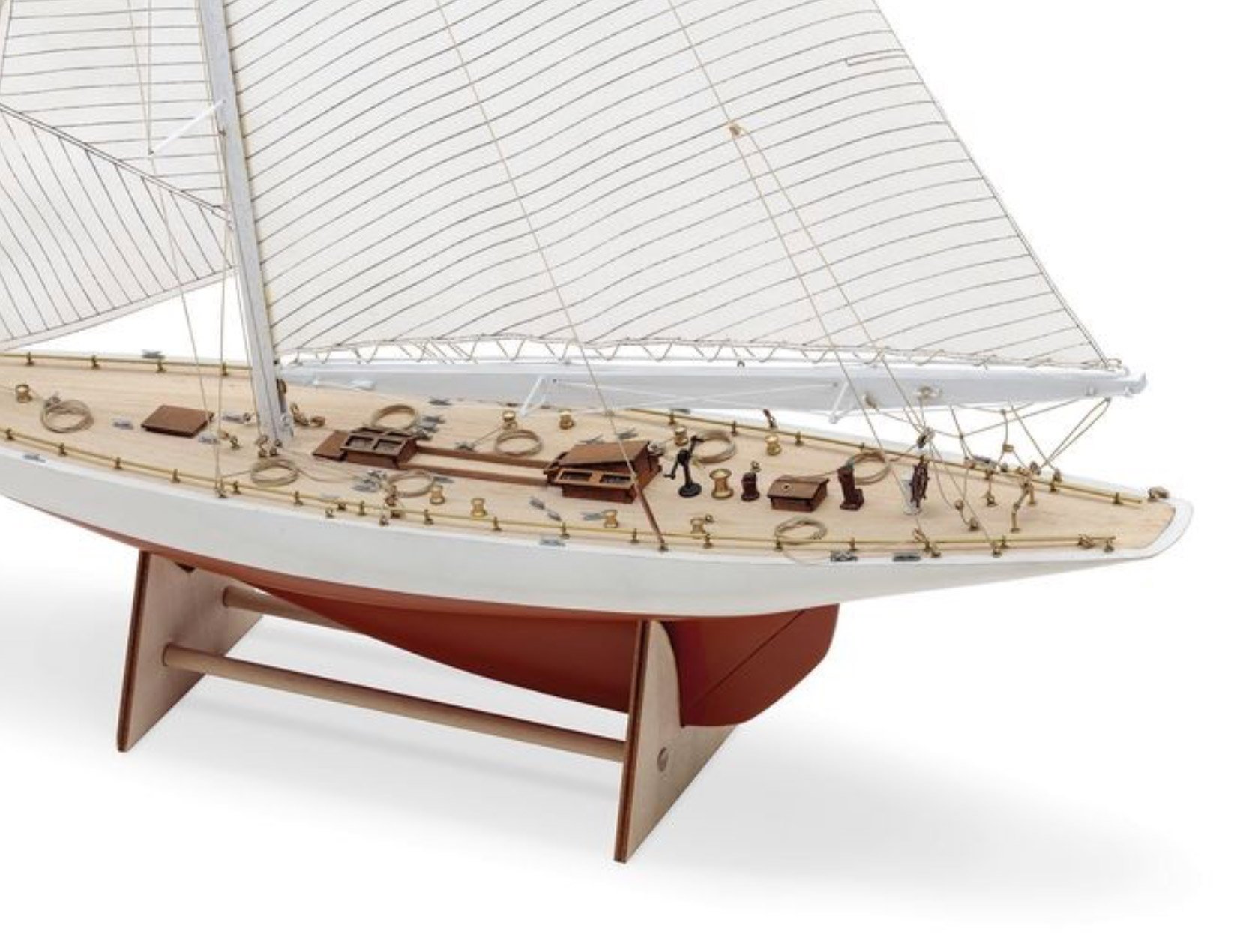
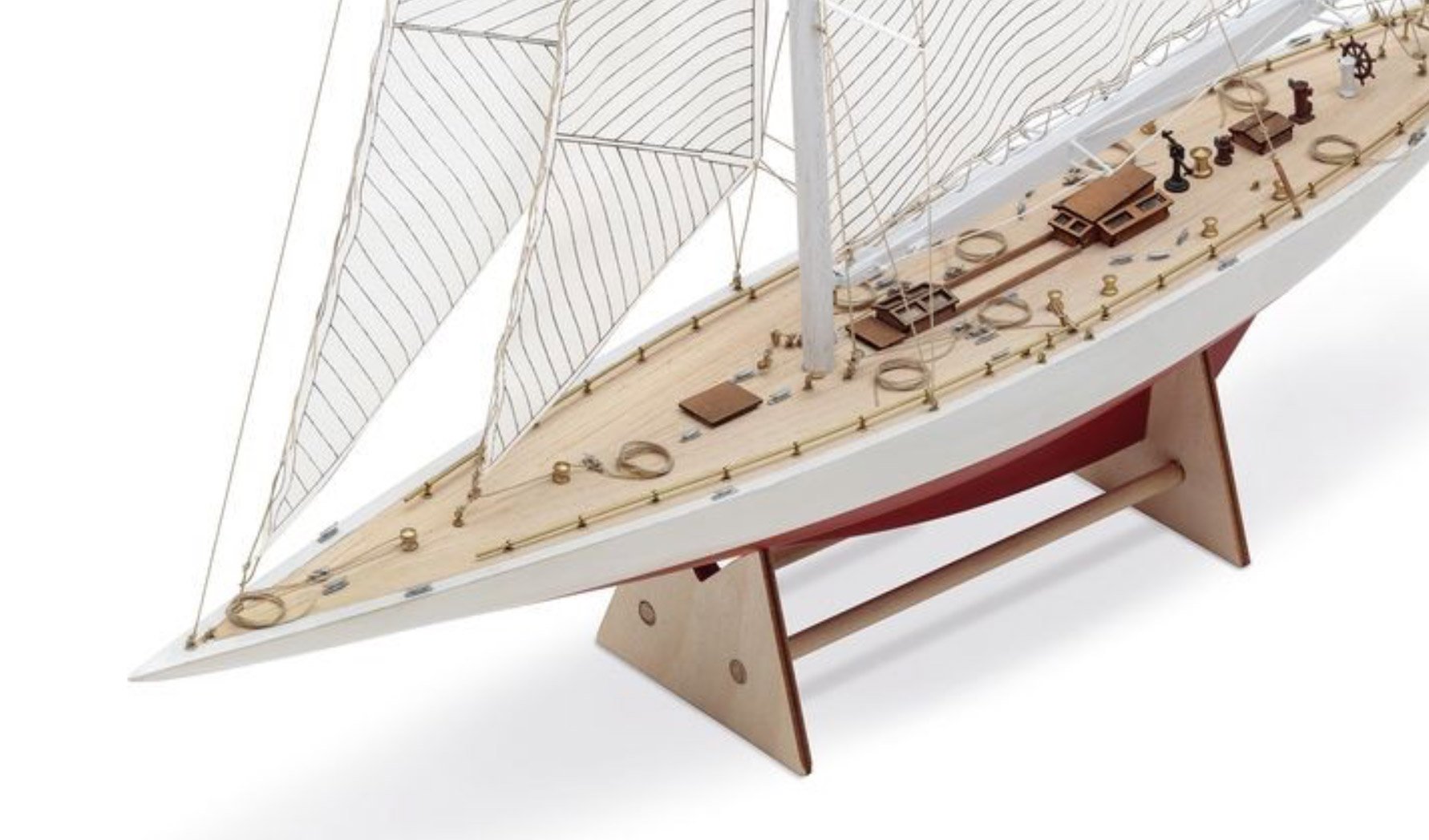
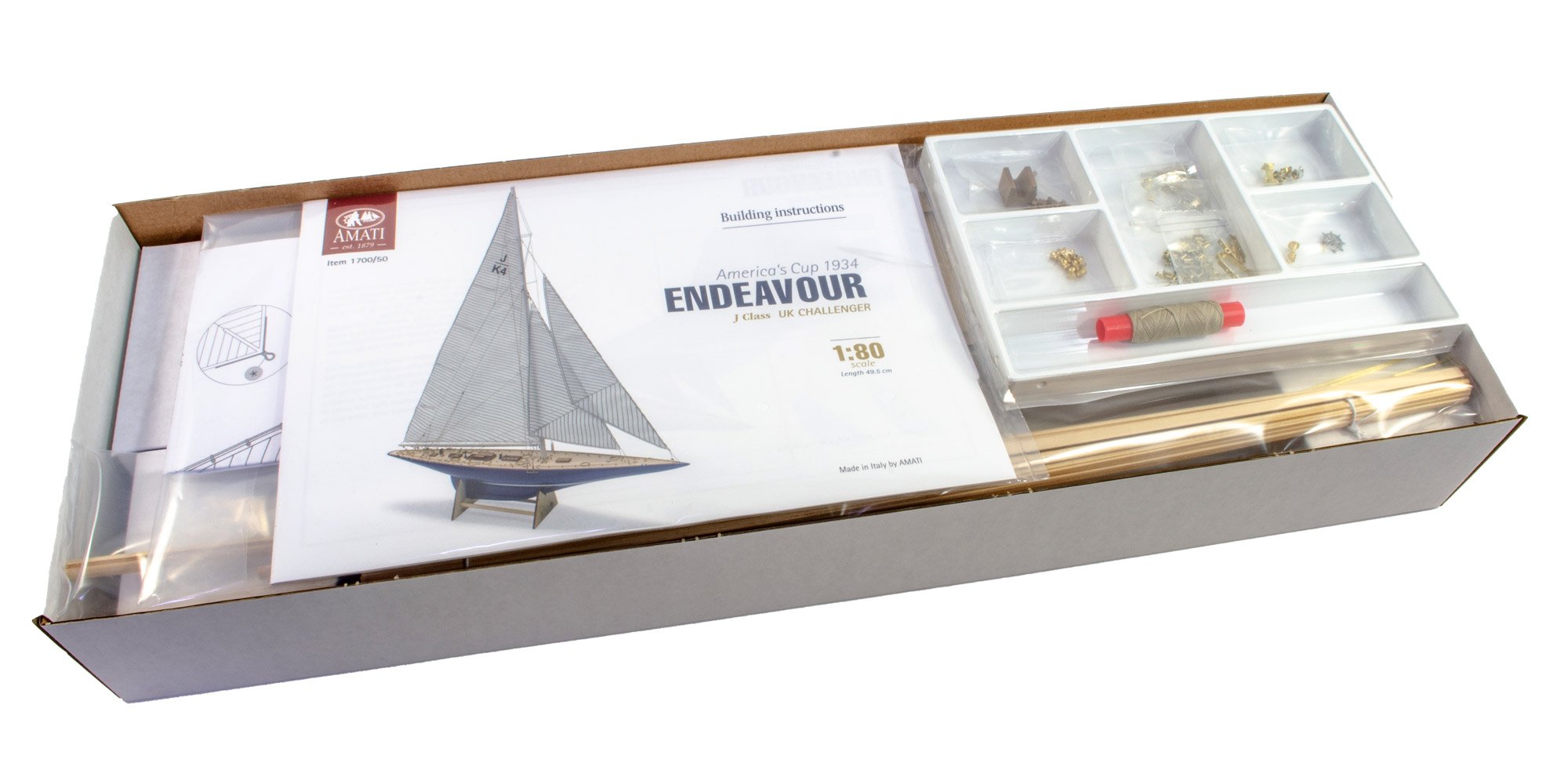
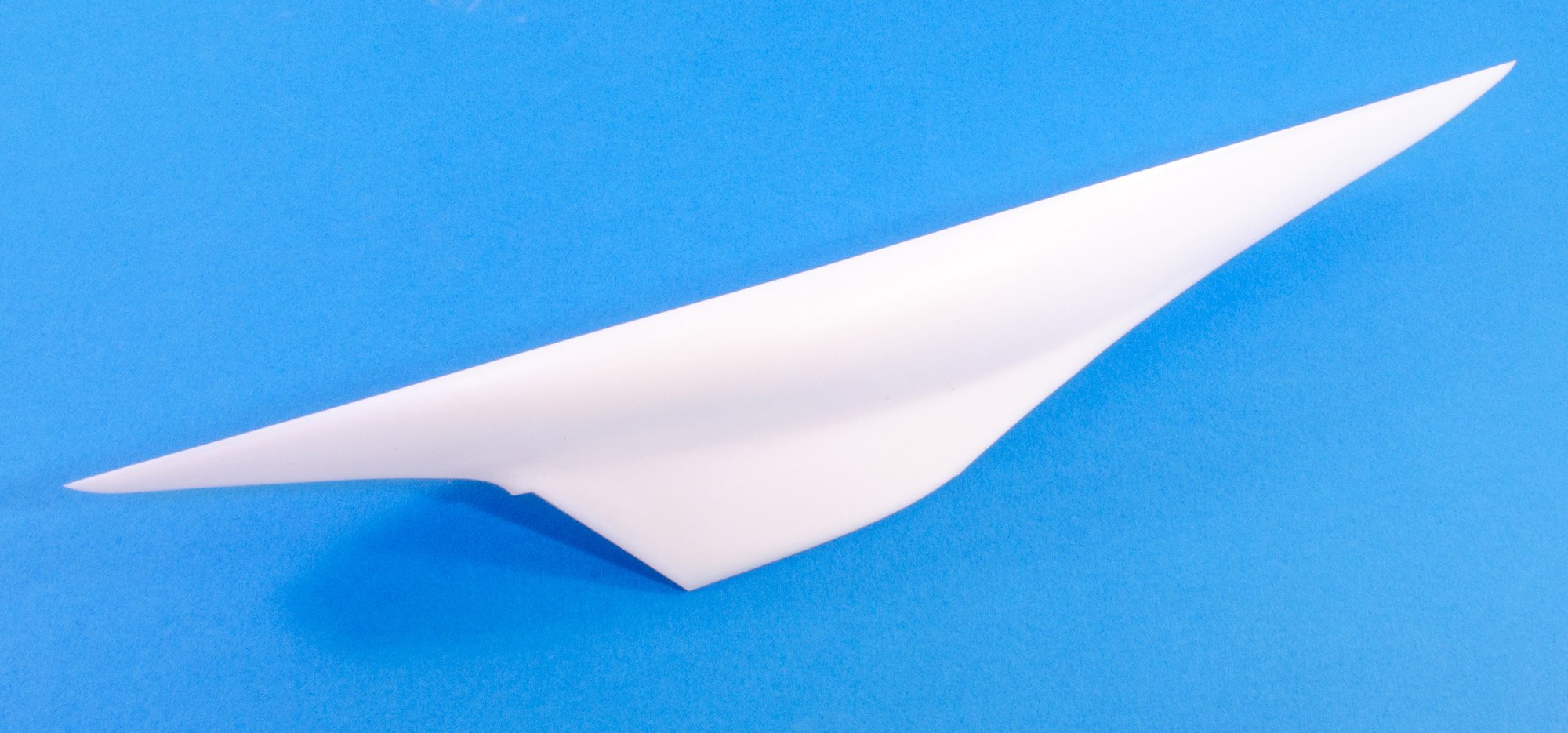
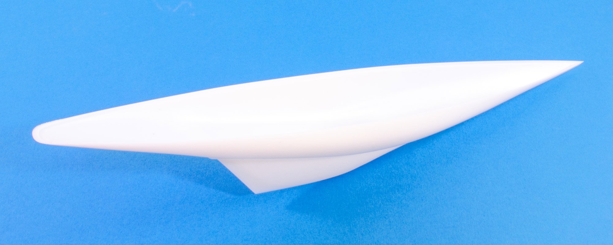
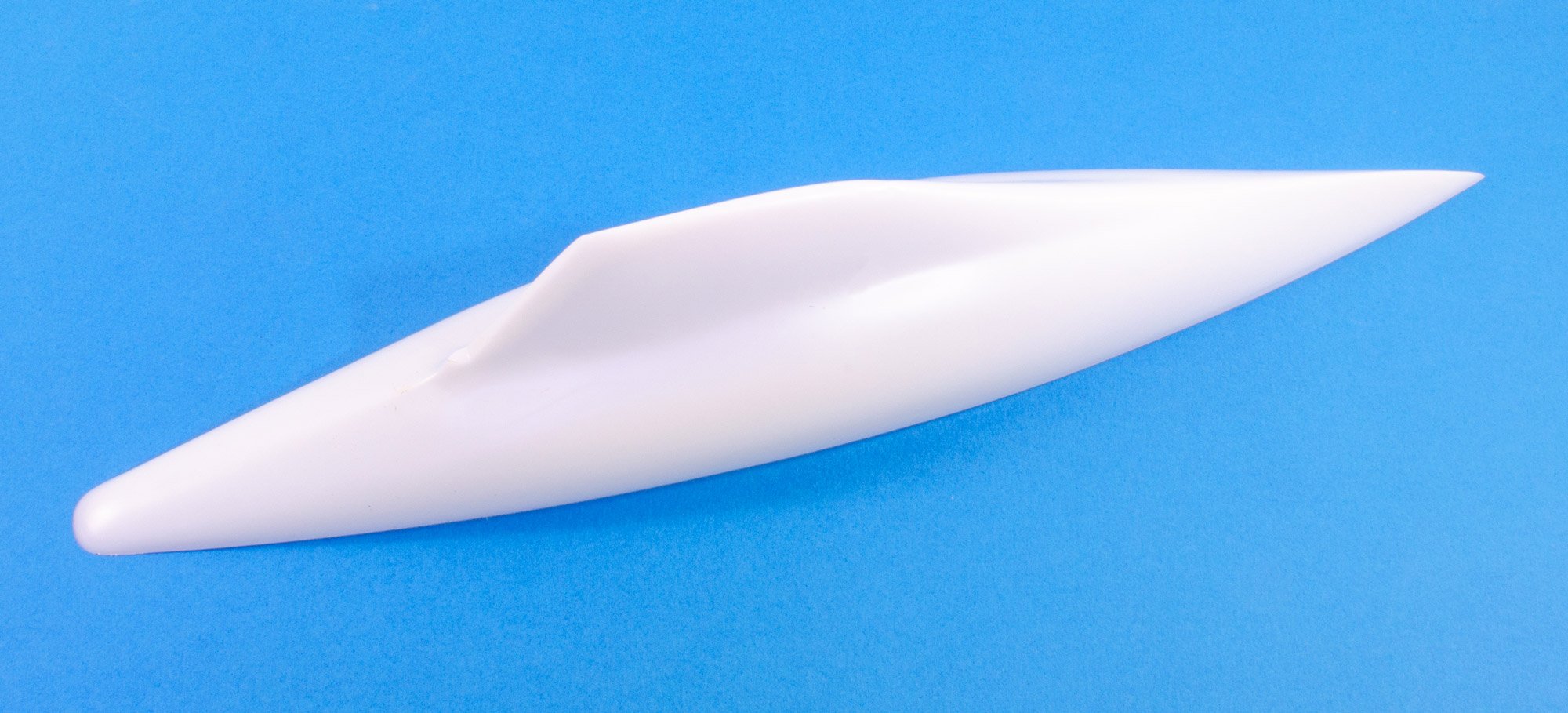
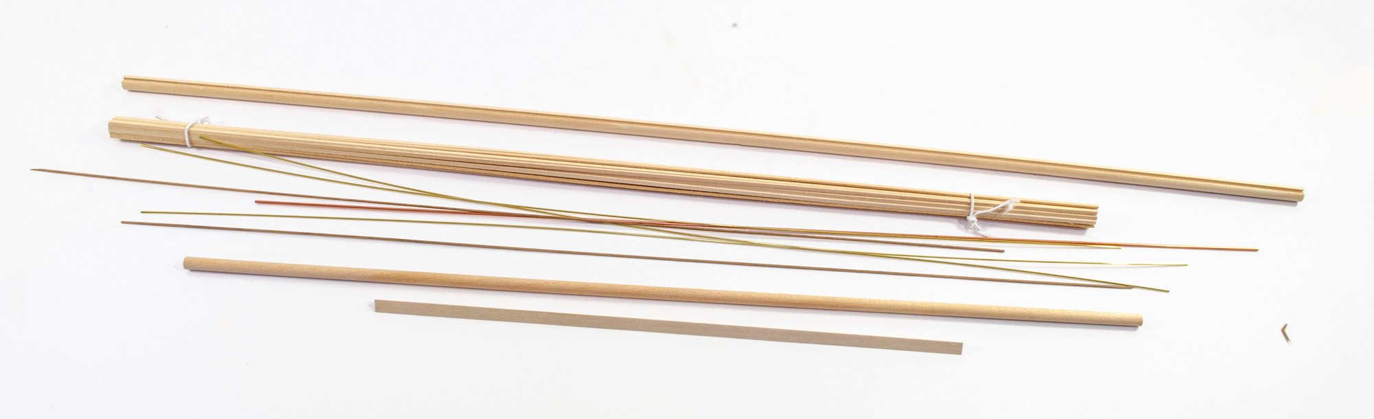
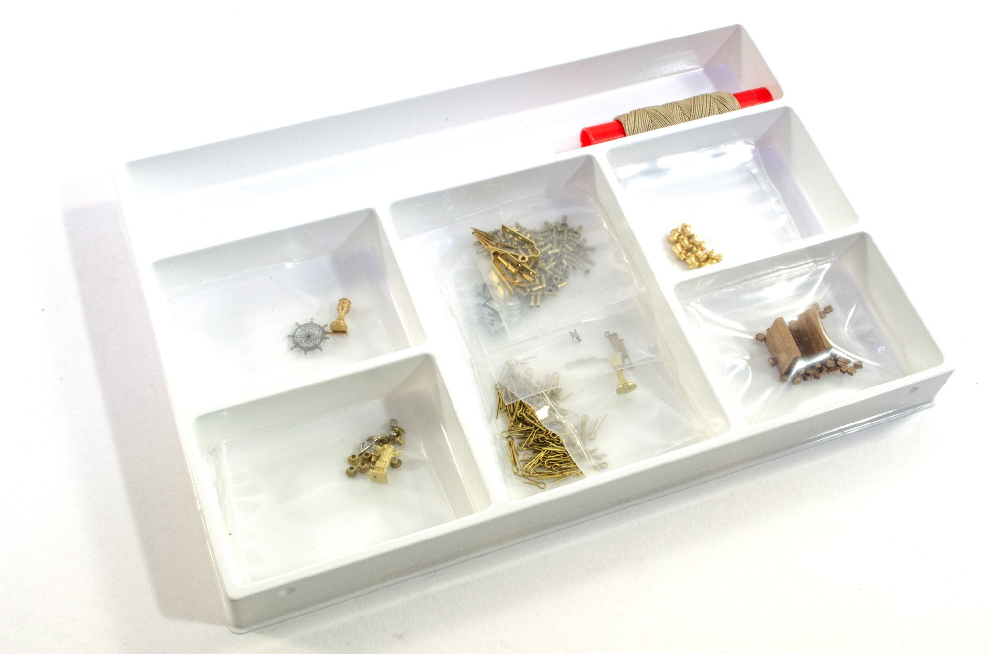
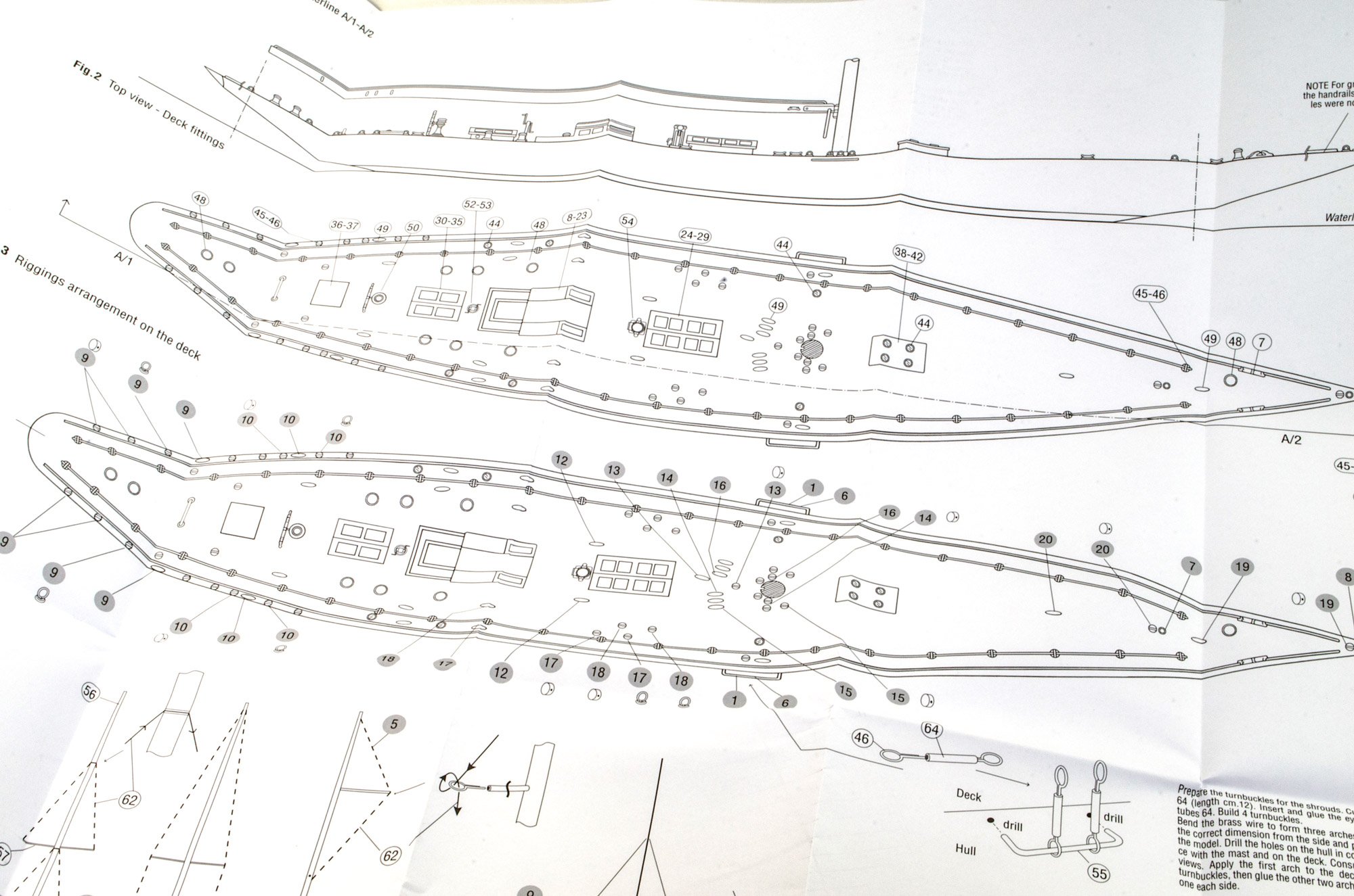
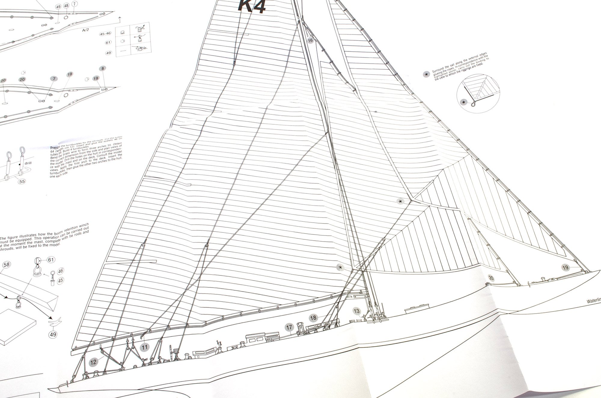
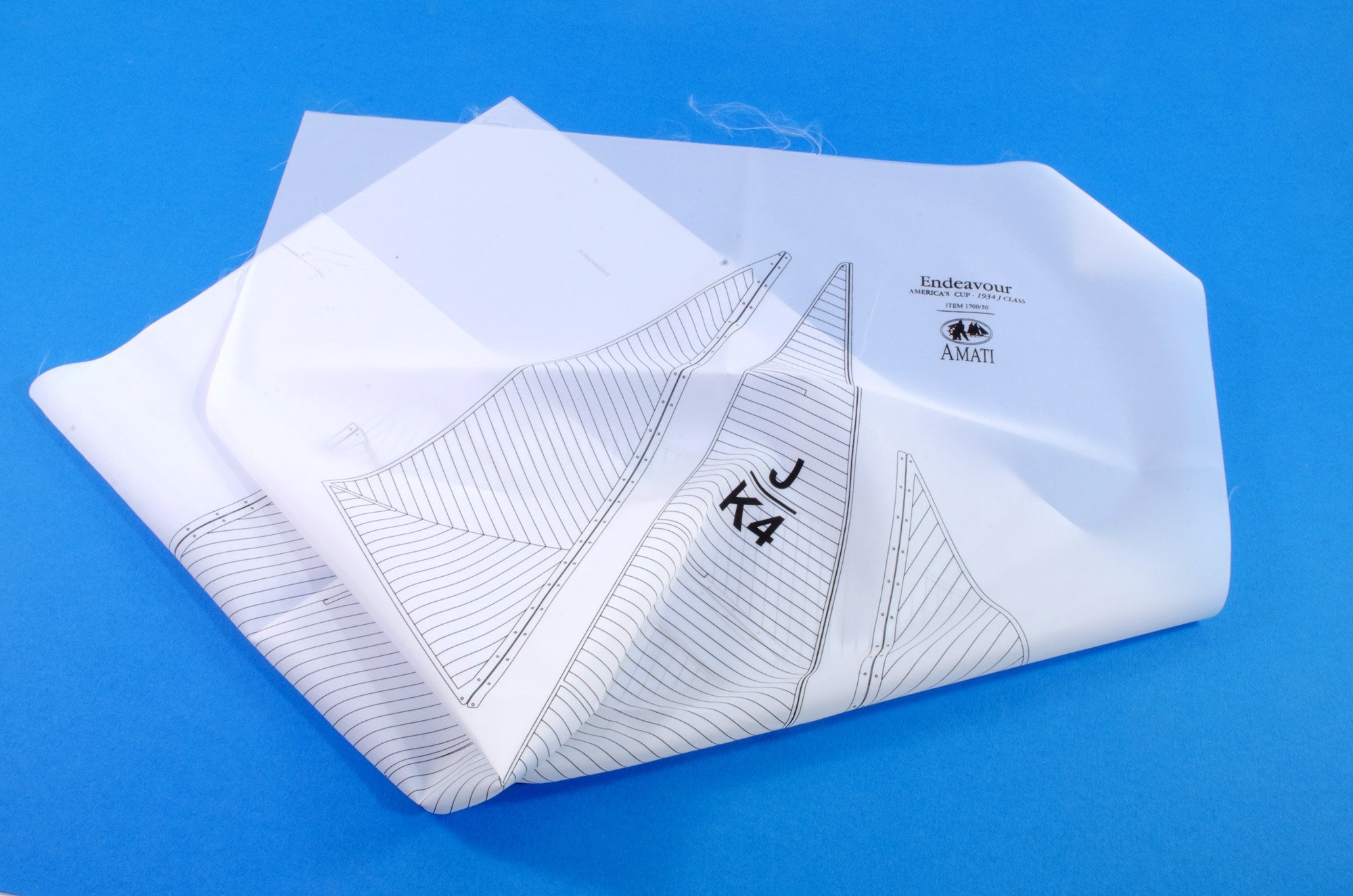
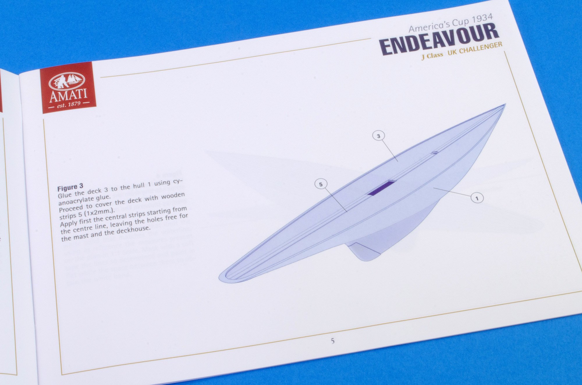
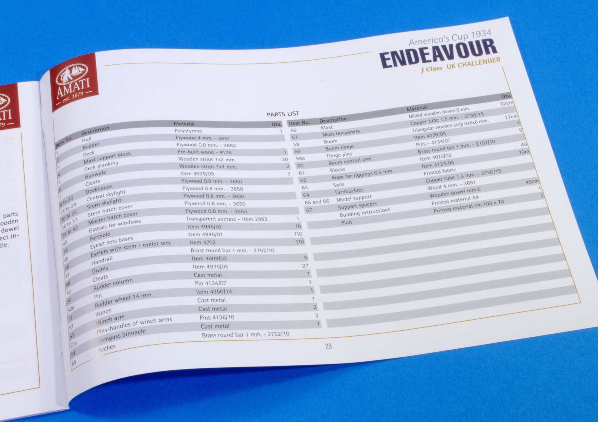
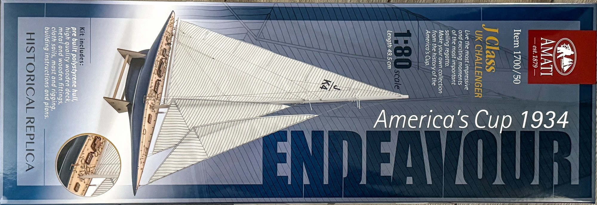
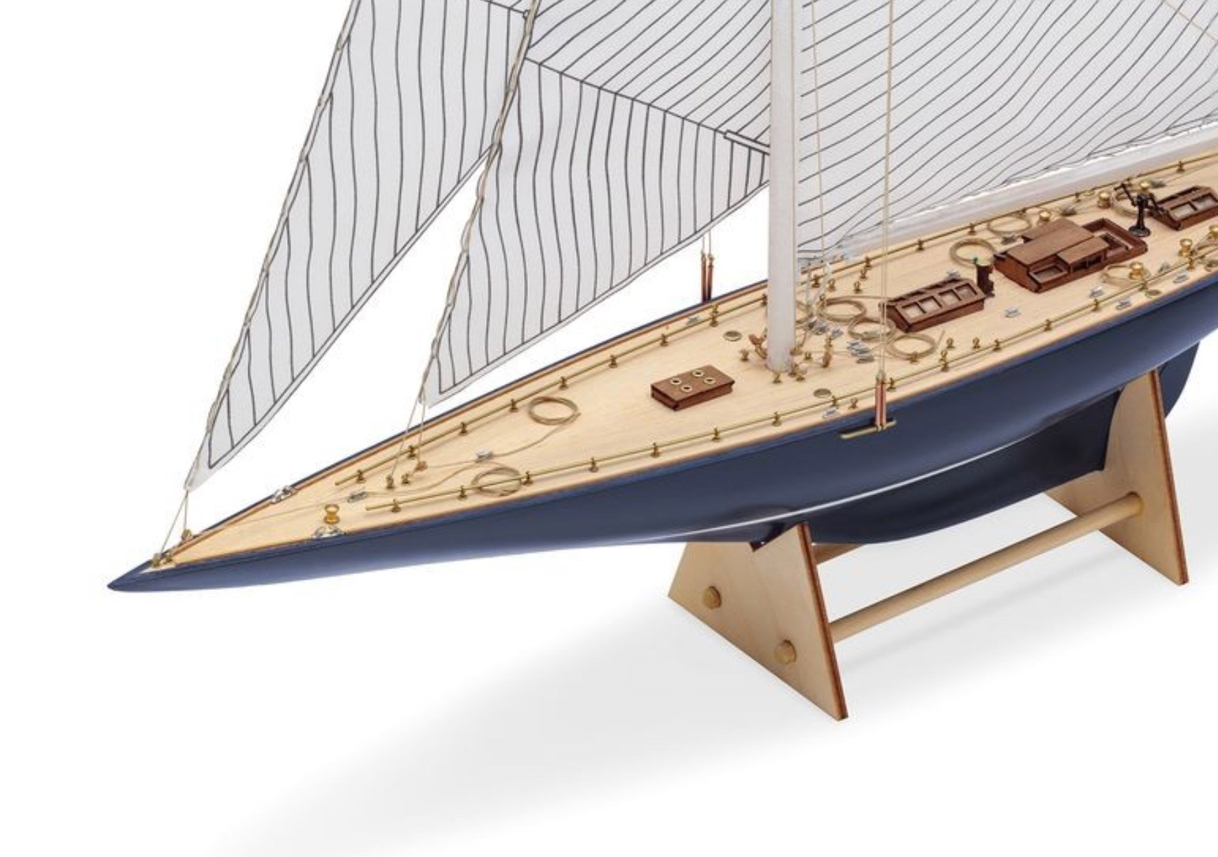
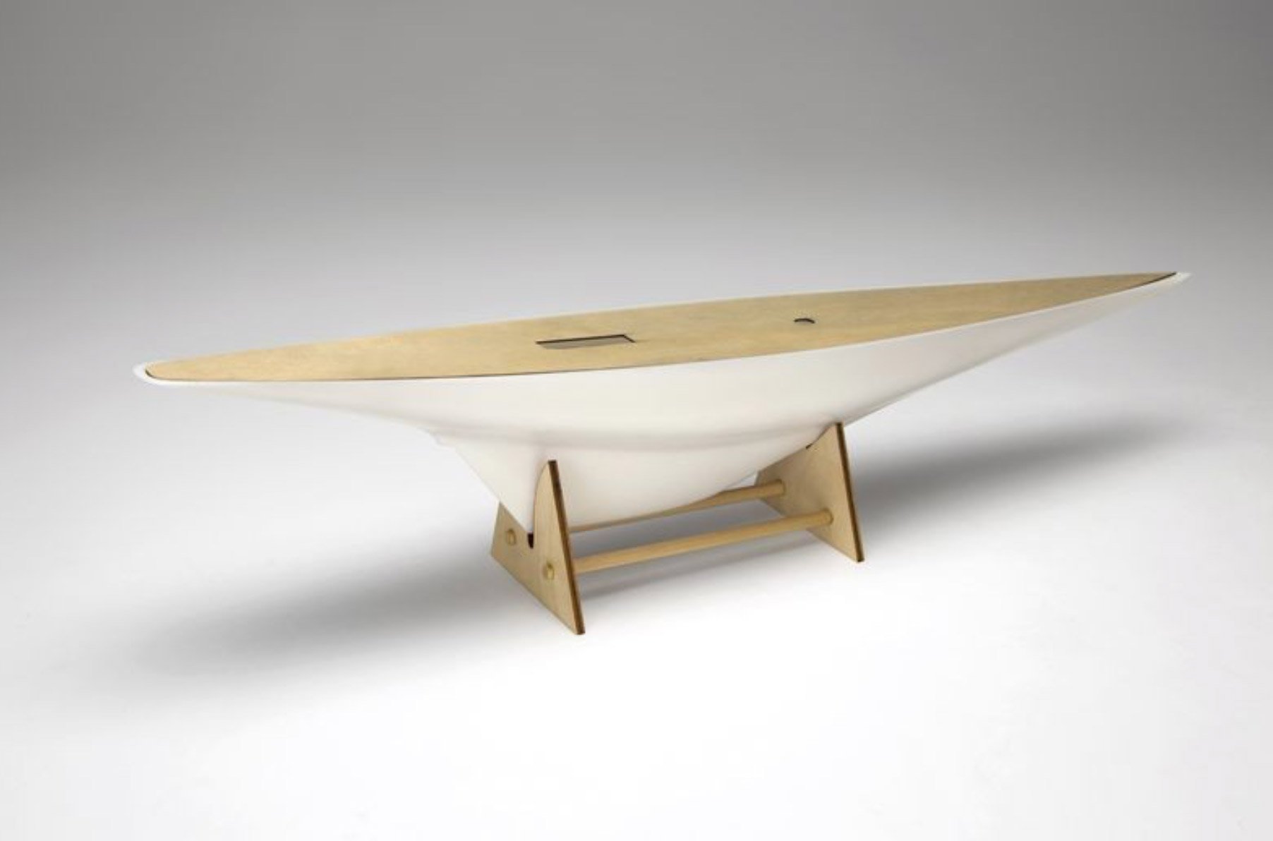
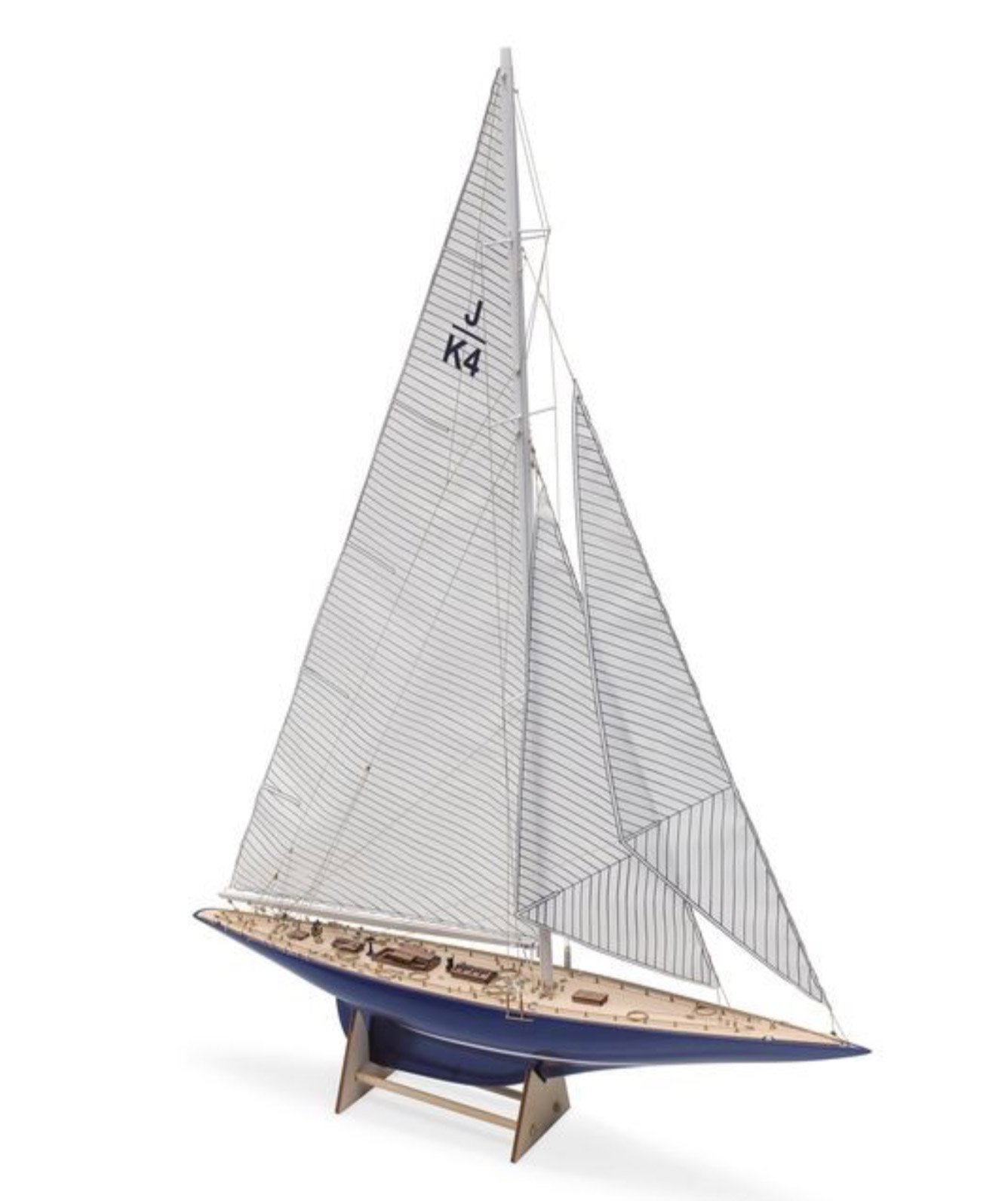
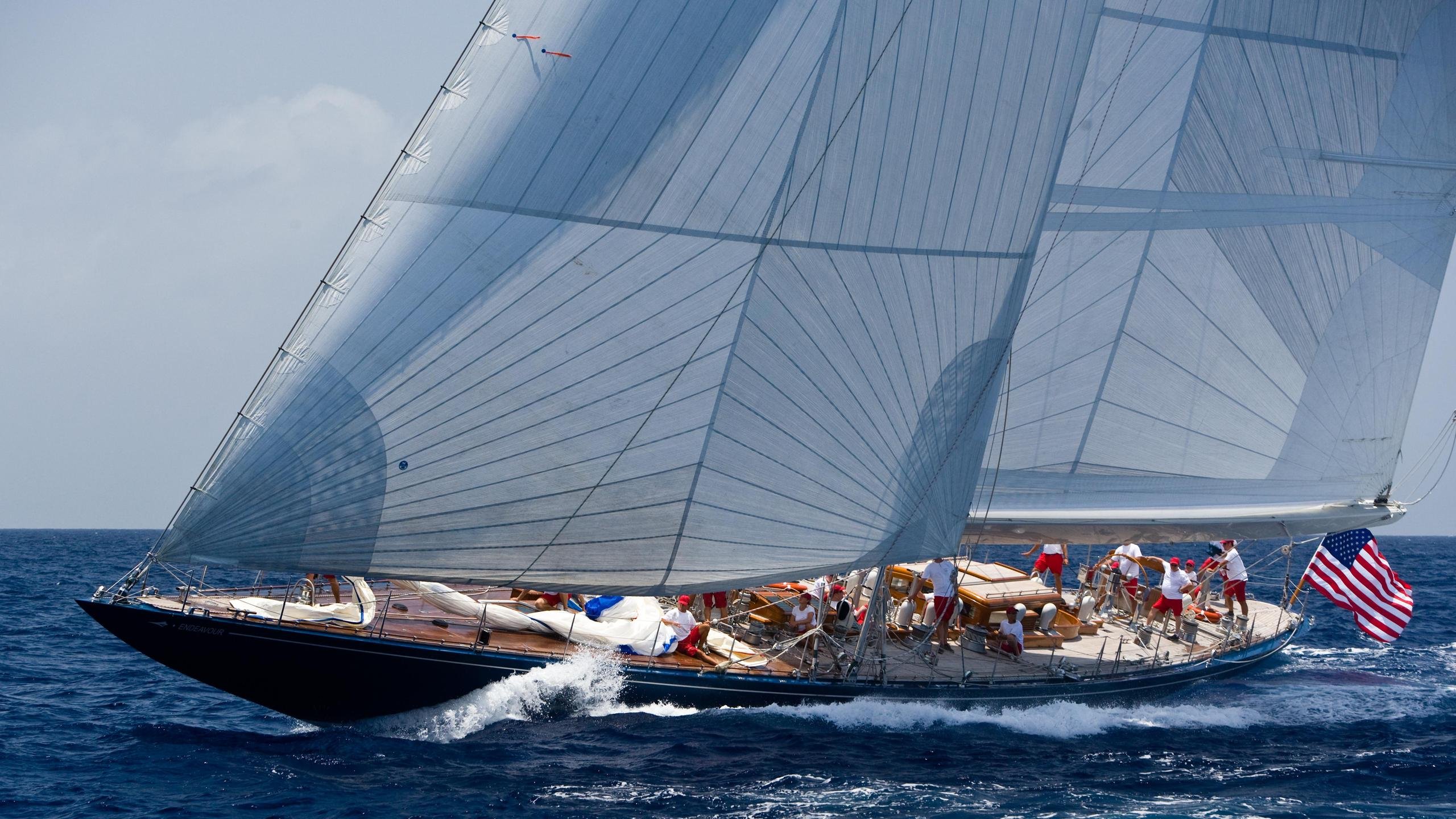
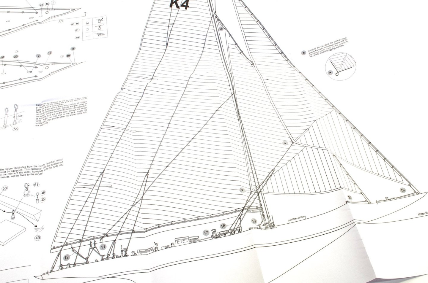
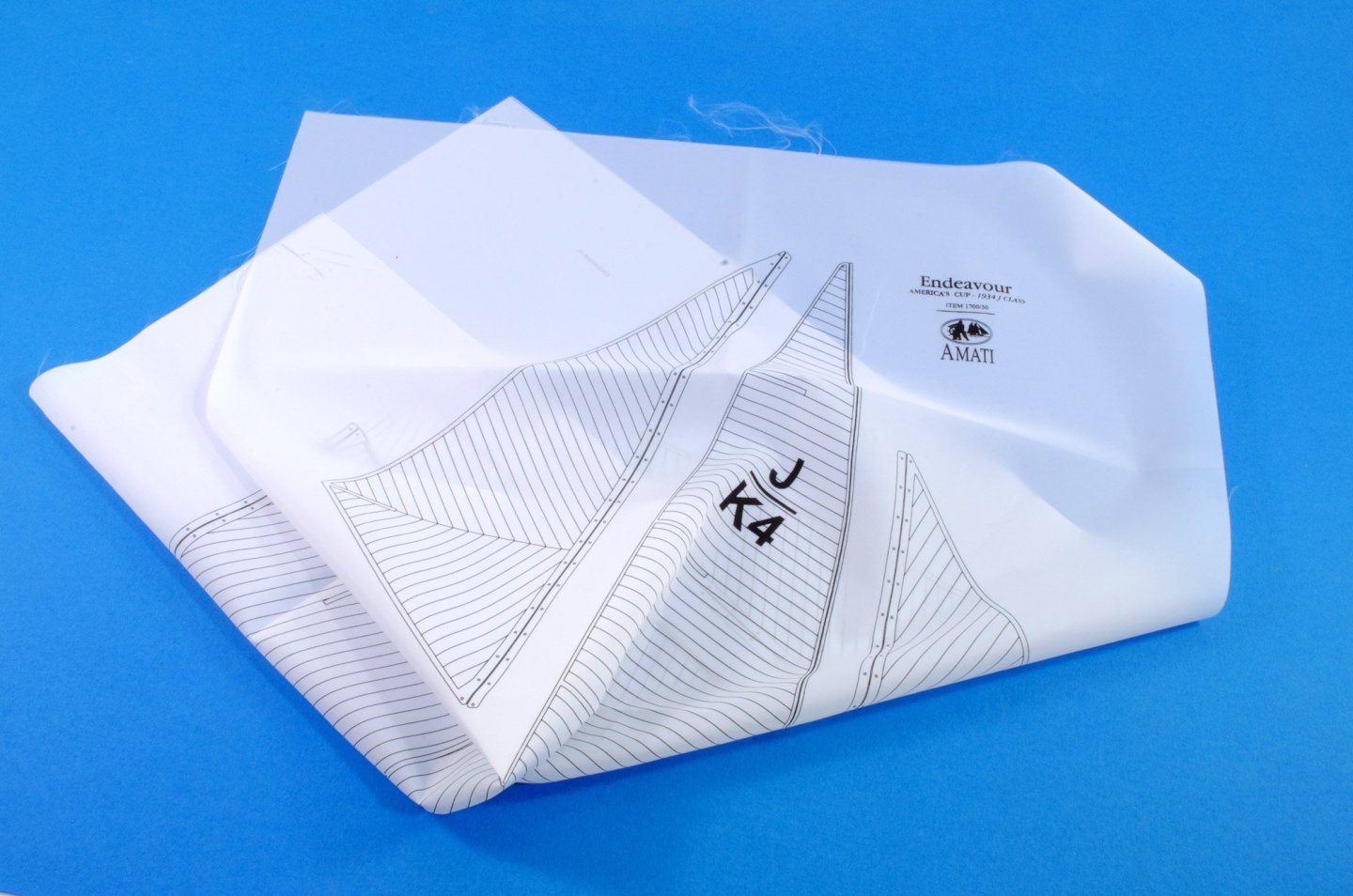
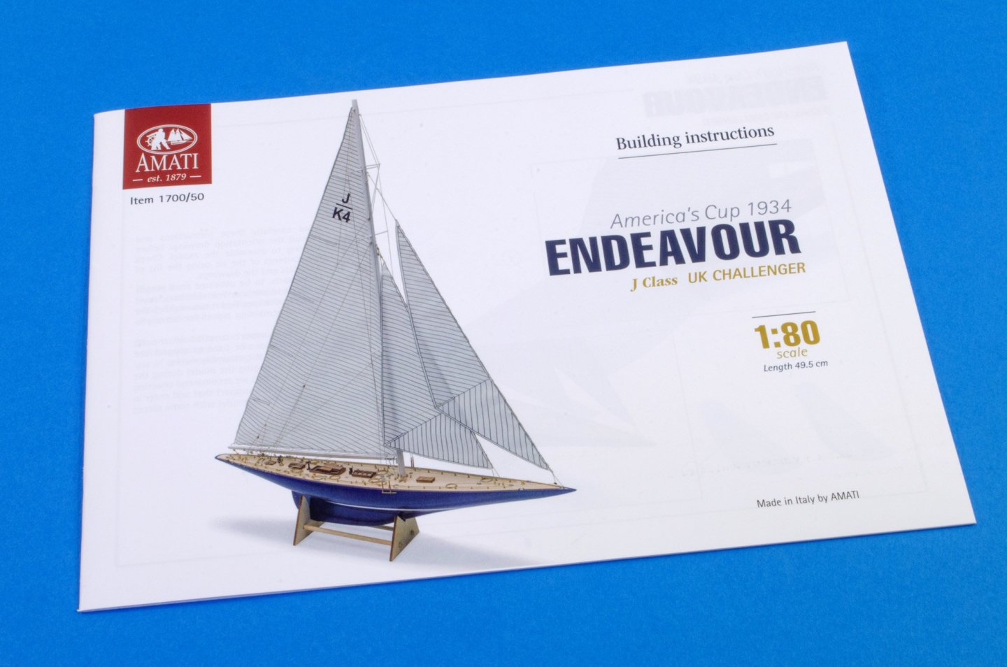
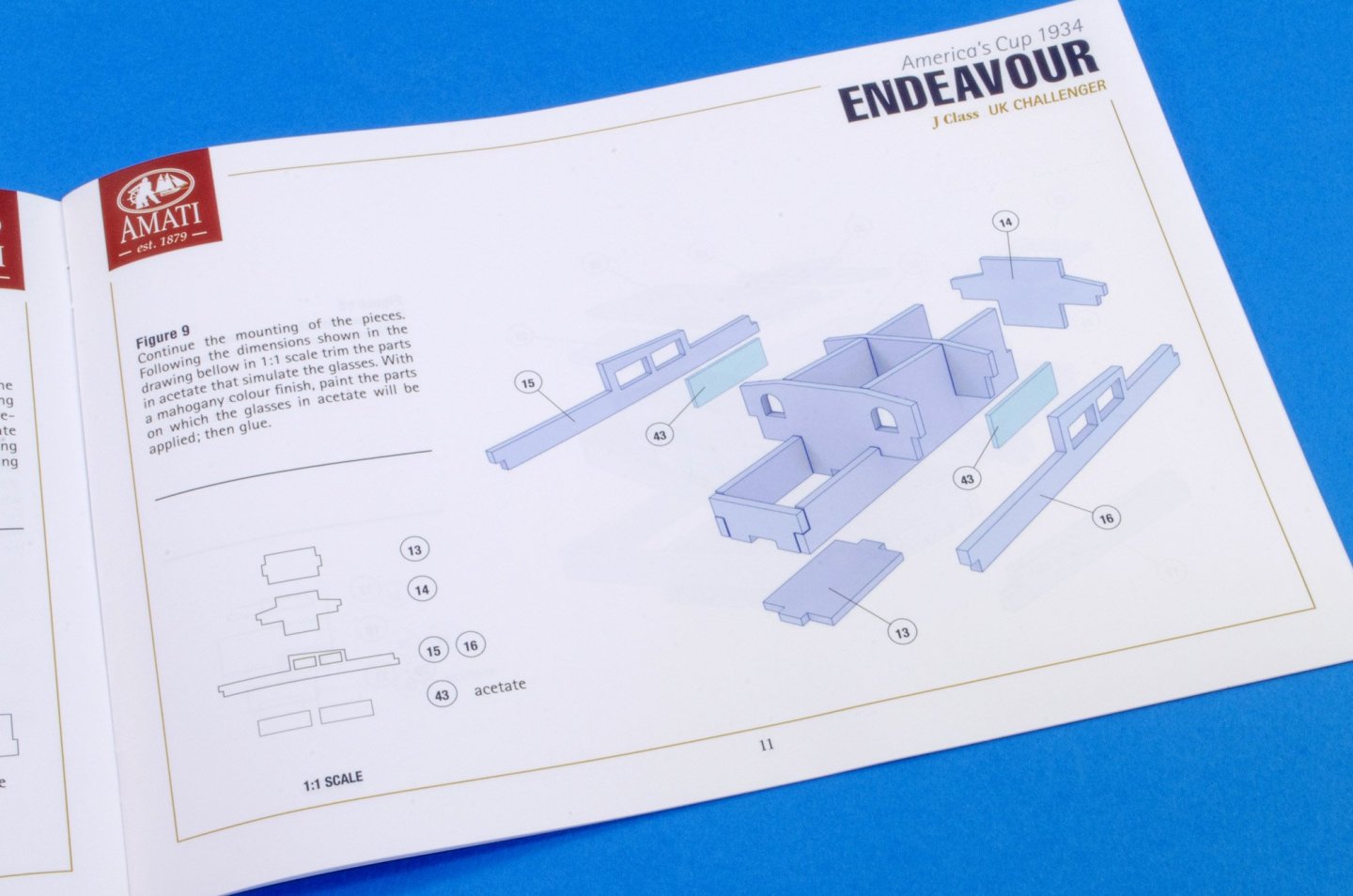
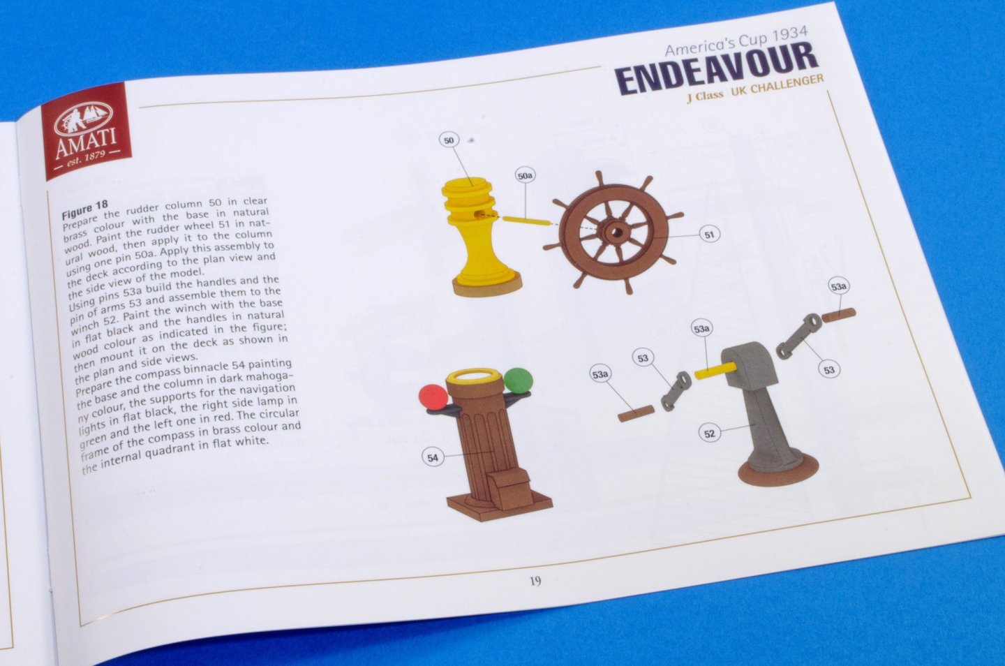
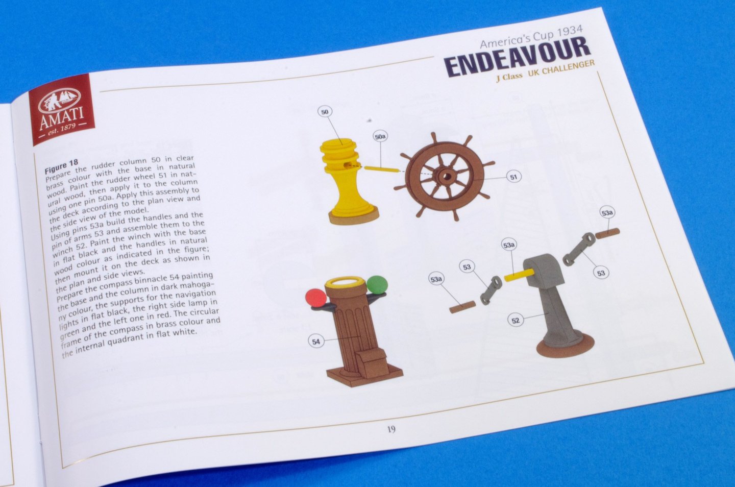
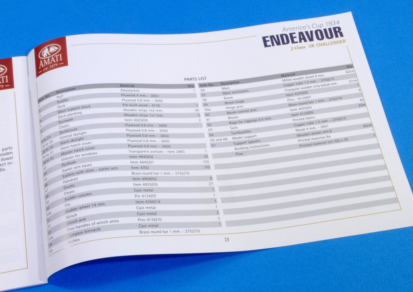
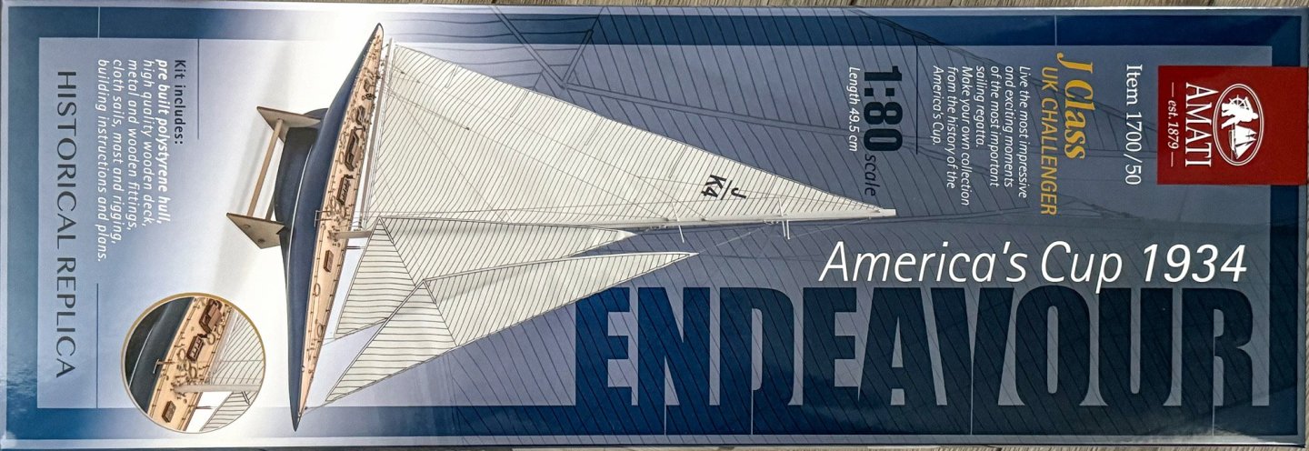
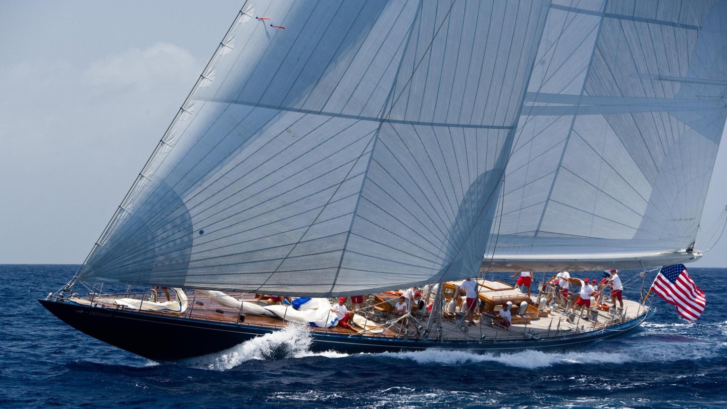
1:80 Endeavour – America’s Cup 1934 Amati Catalogue # 1700/50 Available from Amati for €78,69 History Endeavour is a J-class yacht built for the 1934 America's Cup by Camper and Nicholson in Gosport, England. She was built for Thomas Sopwith who used his aviation design expertise to ensure the yacht was the most advanced of its day with a steel hull and mast.[1] She was 130-foot (40 m) and launched in 1934 and won many races in her first season including against the J's Velsheda and Shamrock V. She failed in her America's Cup challenge against the American defender Rainbow but came closer to lifting the cup than any other until Australia II succeeded in 1983. Endeavour was designed by Charles Ernest Nicholson, and construction was of steel throughout. She was originally fitted with a flexible boom that allowed the foot of the mainsail to bend into an aerodynamically efficient shape. The 1930 Cup winner Enterprise had demonstrated the advantage of allowing the foot to bend this way, albeit using a completely different mechanism (the "Park Avenue" boom). Endeavour's flexible boom broke during trials, and she sailed the 1934 regatta season with an ordinary, rigid boom. In 2006, Endeavour was sold to Hawaiian resident Cassio Antunes for $13.1M. In 2011, she completed an 18-month refit in New Zealand, during which a carbon-fibre mast and standing rigging were fitted, and some changes were made to the deck layout. In summer 2015, it was reported that Endeavour was again for sale, with an asking price of €19,950,000. (Abridged from Wikipedia) The kit Amati’s Endeavour kit is packed into a sturdy and glossy lid-opening box with a photo of the completed model on the front, plus an important dimension stating that the model has a length of 49.5cm. Curiously, for a tall yacht, the height isn’t given. For your info, the model height (taken from the plan sheet) is approx. 67cm tall and 8.8cm wide. This model is also supposed to be suitable for RC. Under the lid, all of the components are elevated by the packing that holds the single-piece, white styrene hull. The moulding of this looks nigh on perfect with a totally smooth finish. No internals are provided for this if you wish to go RC. You’ll need to fathom motor and shaft mounts yourself. For most of us, that doesn’t matter. The rudder is a separate wooden part. The hull is well packed so that it can’t move about whilst in the box. Two sheets of ply are included. These are actually the only timber sheets in the whole kit! The main sheet contains the single-piece deck with superstructure and mast openings. This will need to be planked. There are straight planks which run centrally, but then you need to begin the next phase of planking from the outside edges, working towards the centre. The beauty of this deck will be in the fitting out. On this sheet, there are other parts which are used to build up the various superstructures such as the central and stern skylights. The second, smaller sheet contains the fore and aft display stand parts and also the yacht’s rudder which needs to be shaped. This yacht will need some glazing and this clear sheet is provided for this purpose. There is a nice bundle of strip material in this kit, from the slotted/milled mast, though to deck planking etc. A small quantity of brass and copper is also included. I have to say the timber quality is excellent and very nicely milled/cut. A single tray of fittings is included, with everything packed into bags within. This includes cleats, portholes, eyelets, drums, winch and arm, wheel, binnacle and rigging cord etc. Fittings quality is up to Amati’s usual high standard. One plan sheet is included with the main drawings at 1:1. Whilst the instruction booklet deals with all things to general construction, plus some other elements such as rudder wheel etc, the plan is what you need to refer to for fittings placements, masting and adding sails and rig. White sail material is included. This has all of the yacht’s sails printed on it. You will need to carefully cut these from the sheet and then finished before fitting. A 24-page colour manual is included. This covers all the main stages of construction, and some of those which are best illustrated in 3D instead of in plan form. All illustrations are very clear, with the specific parts shown in plan form, adjacent to the 3D illustrations, complete with part numbers. These numbers can be referenced from the plan sheet. Conclusion If you like graceful hull lines, but hate planking, this is for you. Even if you need a quick but satisfying ‘between projects’ build, then this could hit the mark. There aren’t too many parts to this build, by both nature of kit design and also due to the vessel herself. Once you’ve planked that ply deck and fitted to the hull, it’s very much a fitting out project. The quality of the plastic hull is excellent and you’ve got a real nice base onto which you can then add paint. No plank lines to fill and rub back endless times. She’ll look great in a custom made acrylic case too, and the kit itself is very reasonably priced. My since thanks to Amati for sending out this kit for us to look at on Model Ship World. Check your local dealer for availability. If unable to purchase via dealer, dead onto Amati to buy directly, via the link at the top of the article.


-
How do I create a build log?
James H replied to Fuzznoggin's topic in How to use the MSW forum - **NO MODELING CONTENT**
Please check the many pinned topics in this area. -
Indy should be finished in the next month, so that'll be the right time to start on this one.
- 397 replies
-
- 11
-

-
I'm pretty sure all digital editions will become available.
-
When you insert a photo, Hold down SHIFT and then press RETURN for the next line of text to fall immediately after a photo.
-
Adding a signature to a comment
James H replied to PvG Aussie's topic in How to use the MSW forum - **NO MODELING CONTENT**
Once you get your signature, it is applied to every post you ever made. The option for signatures appears after 10 posts. -
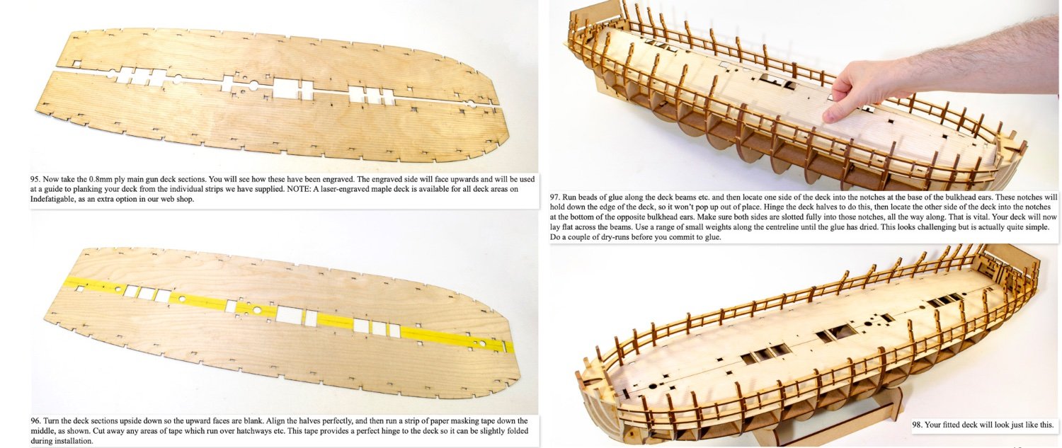
Glad you sorted the deck problem. The tape trick is something I used for the Indefatigable, primarily because the halves were so vast.