tedrobinson2000
-
Posts
153 -
Joined
-
Last visited
Content Type
Profiles
Forums
Gallery
Events
Everything posted by tedrobinson2000
-
I have had good success with Roket (note no "C") cyano glue gel CA. It's a little pricey and hard to find, but works well for most uses, especially planking. Just the tiniest dot (often right out of the tube tip), finger pressure for 15-20 seconds, and it's done. Plenty of time to reposition things if necessary before it grabs.
-
Chuck and Glenn..... thanks for your responses. As for the problems with my stern framing, I'm sure the cause of my misalignment was that the slots in my after bulkheads were not as precise as those from Chuck. This meant that there was not a good friction fit, and my pieces moved around and wouldn't stay put while I was gluing. I think I can fix the misalignment later on by adding a little to the tops of the stern filler pieces to raise that area up a bit. The port/starboard alignment is OK, it's the elevation that is off. As to the wing transoms, my version of the Winnie plans downloaded from MSW do not show that piece, and I missed noticing it in the photos in the monograph. I finally did see it in another member's build log, and then the lightbulb came on and I could visualize how the after bulkheads needed to be faired! Chuck, I'm not averse to asking questions, sometimes I'm stupid enough that I don't know that they need to be asked!! This can be seen by the fact that I didn't recognize that the quarterdeck rail needed to align with the run of the wales! Thanks again, Regards, Ted
-
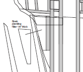
Sorry if I missed it, but here is a snip from my Sheet 3.... it's not there. Maybe it's somewhere else that I missed....my apologies if that is so.
-
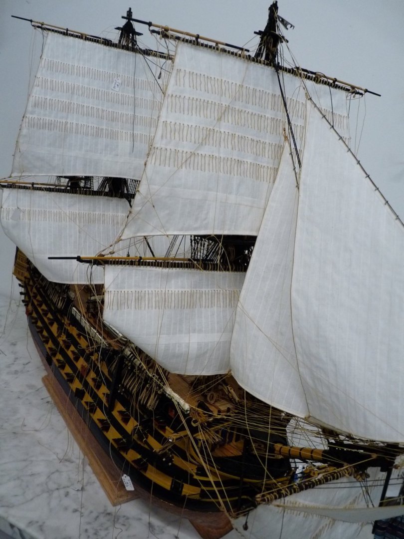
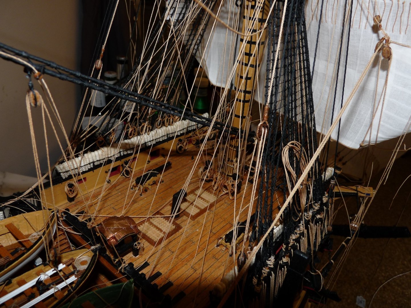
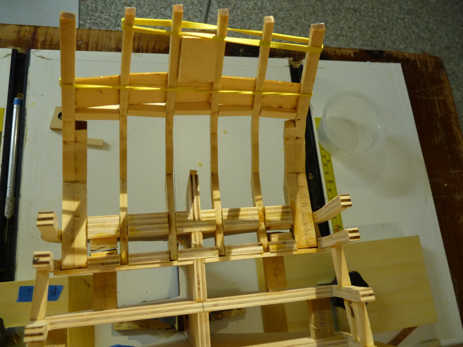
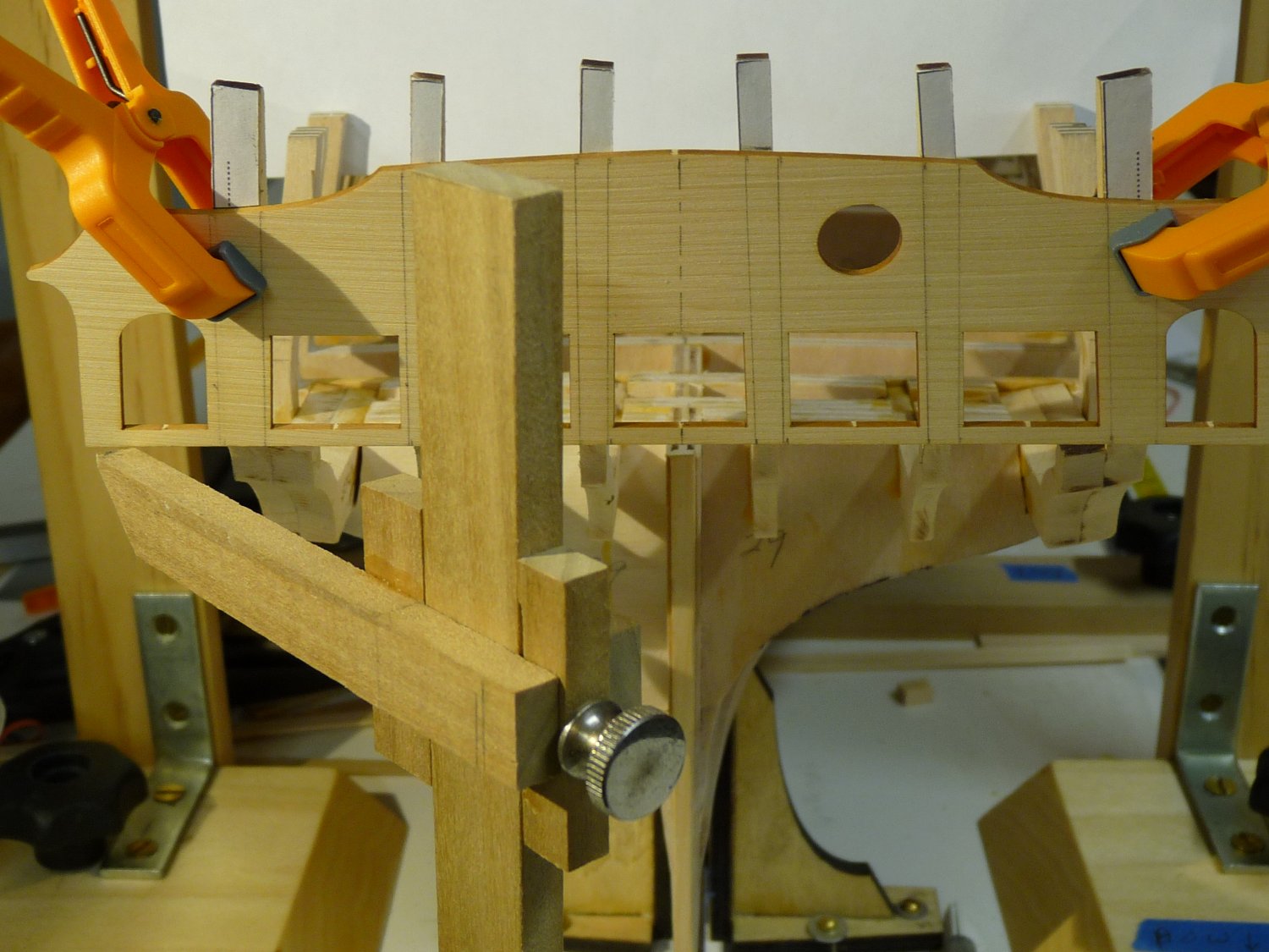
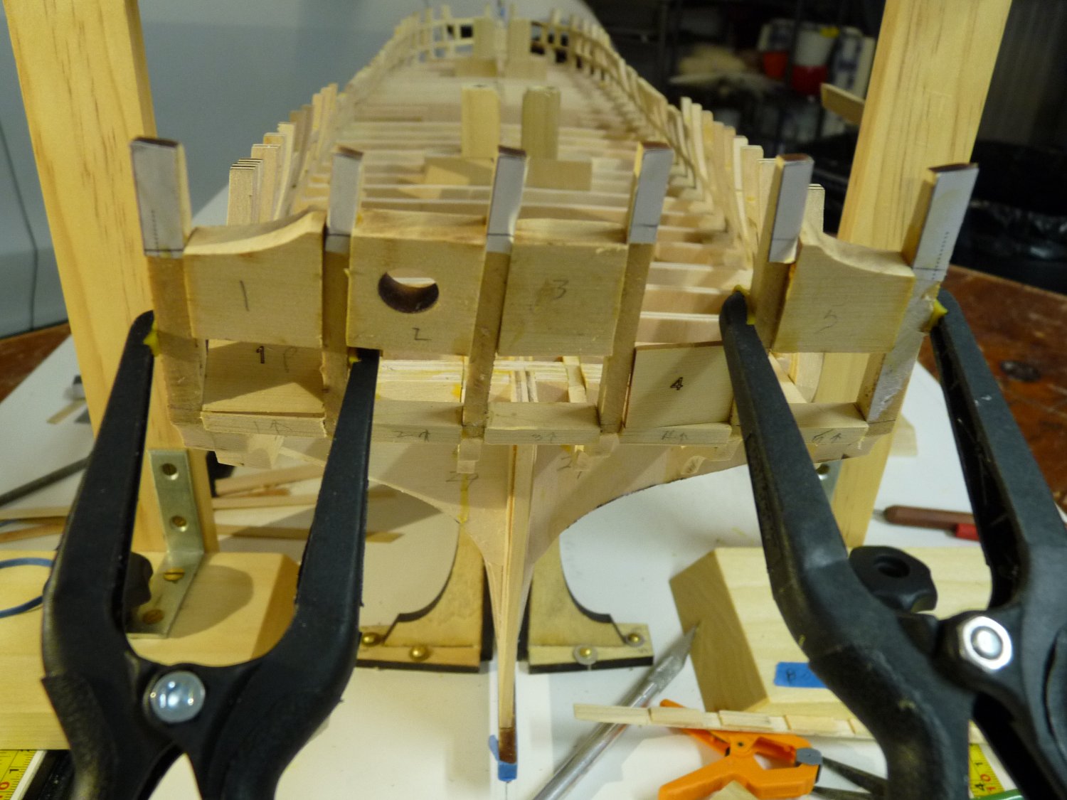
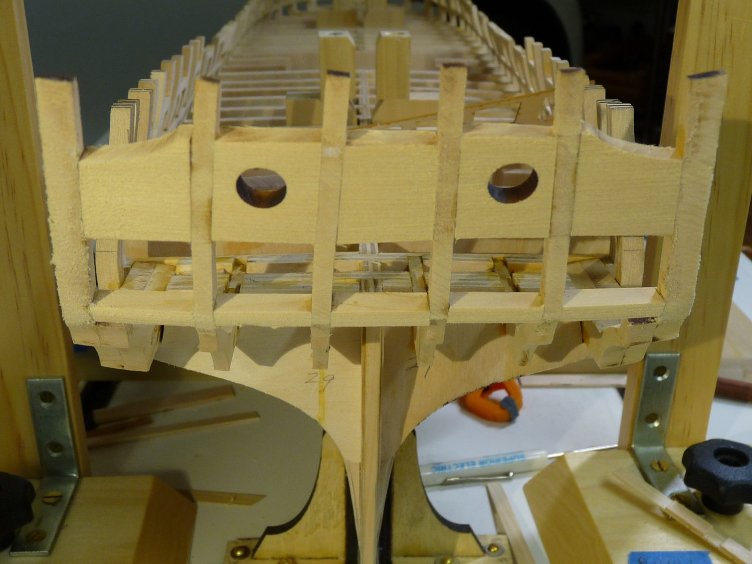
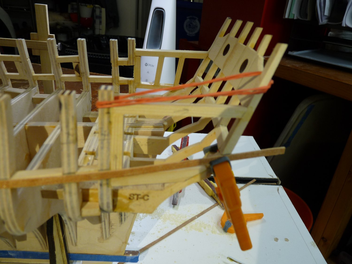
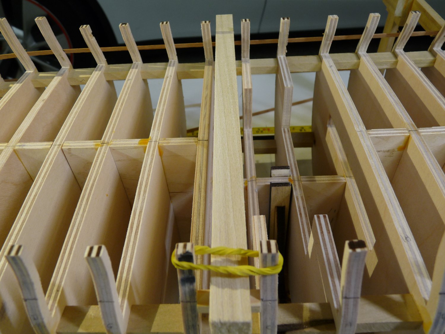
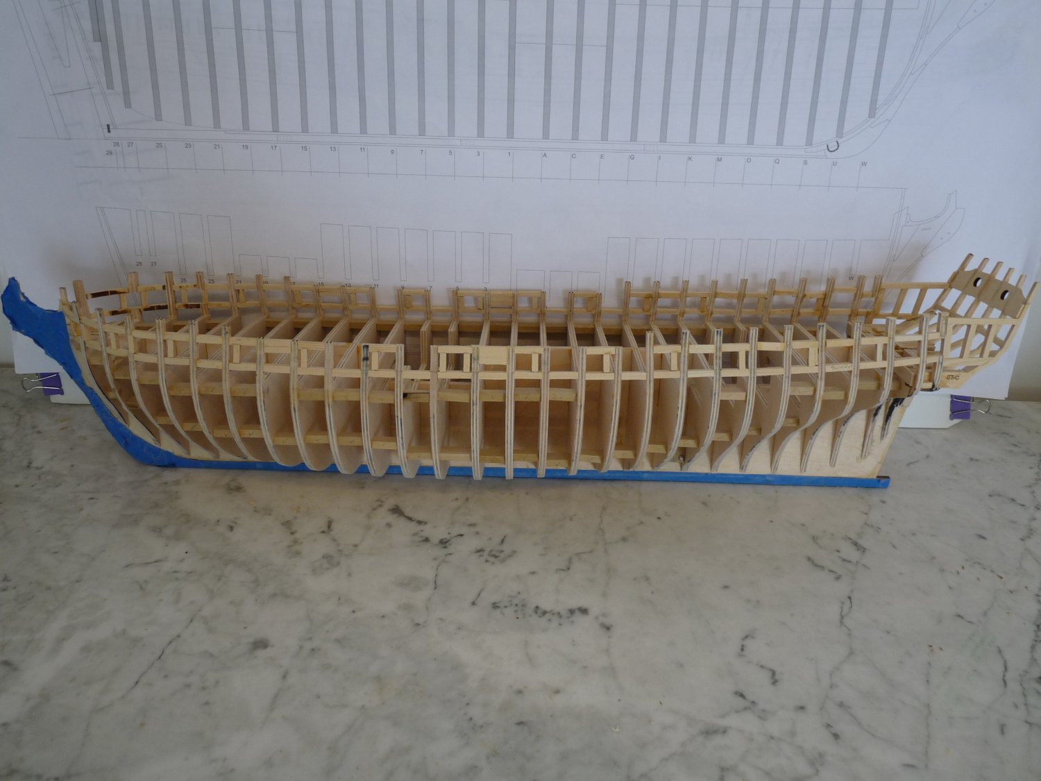
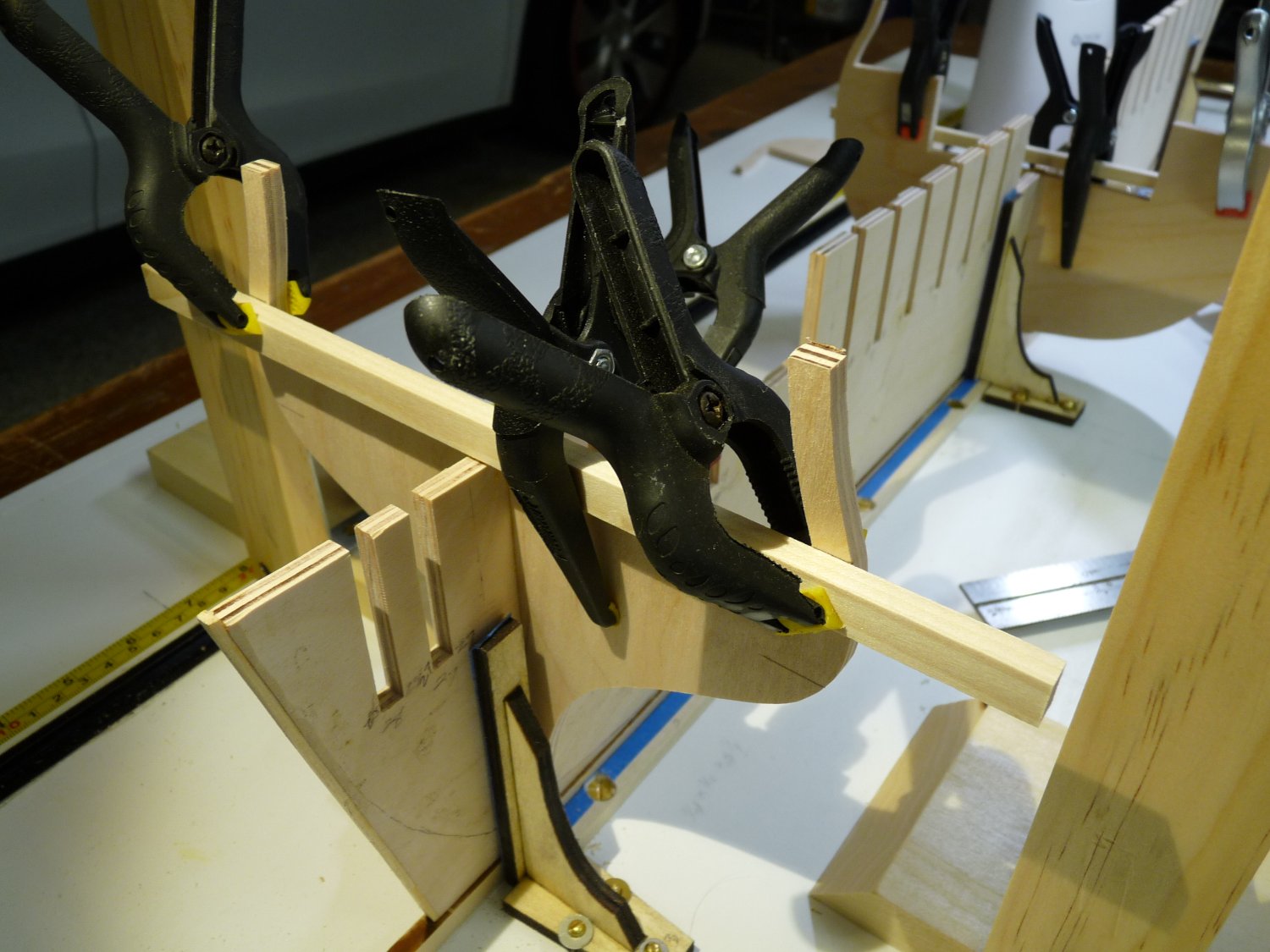
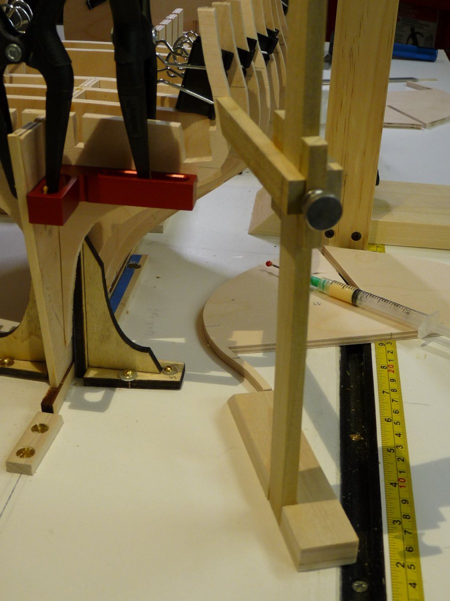
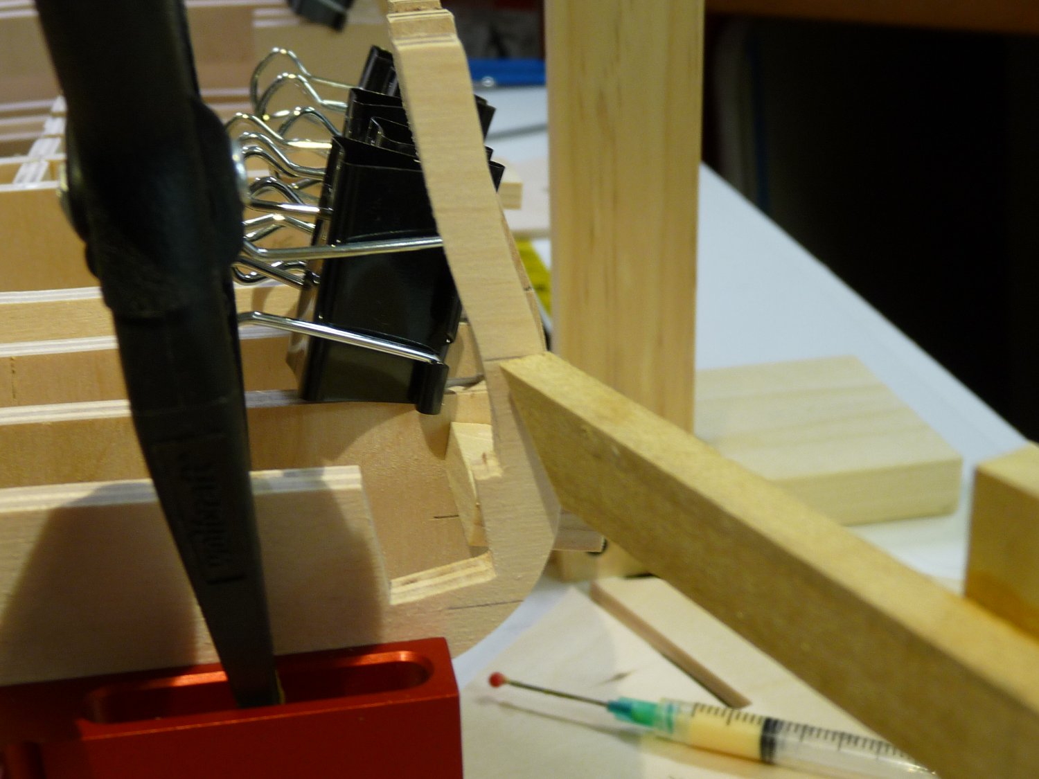
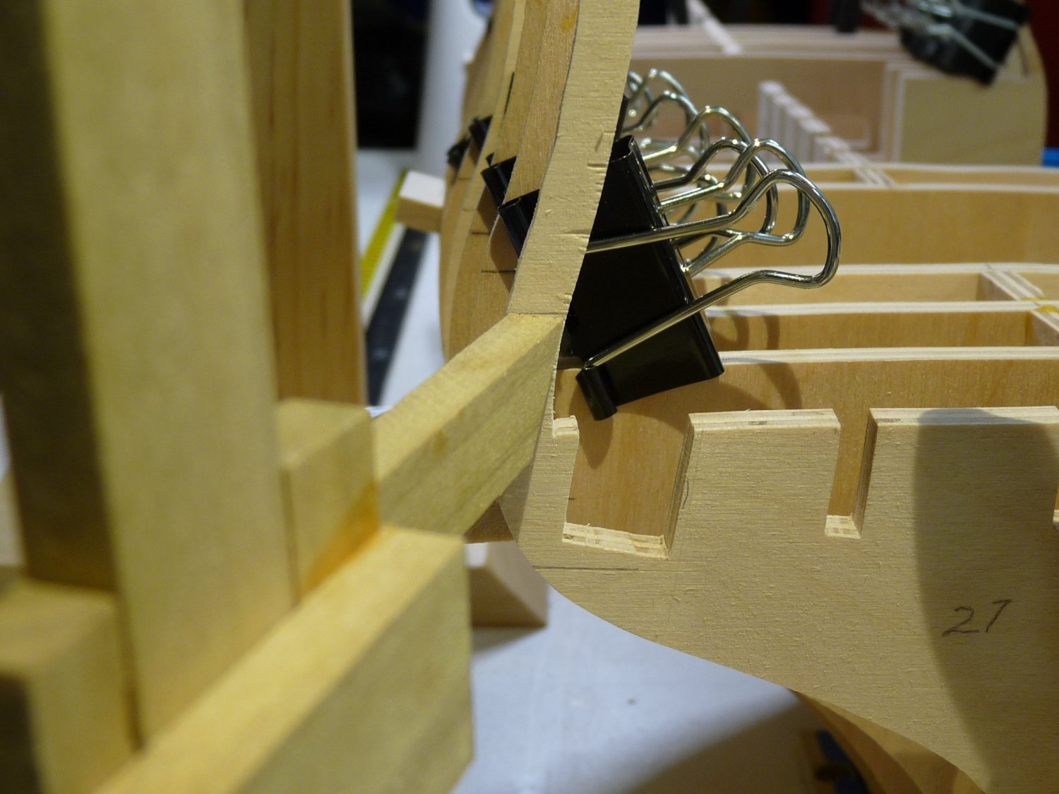
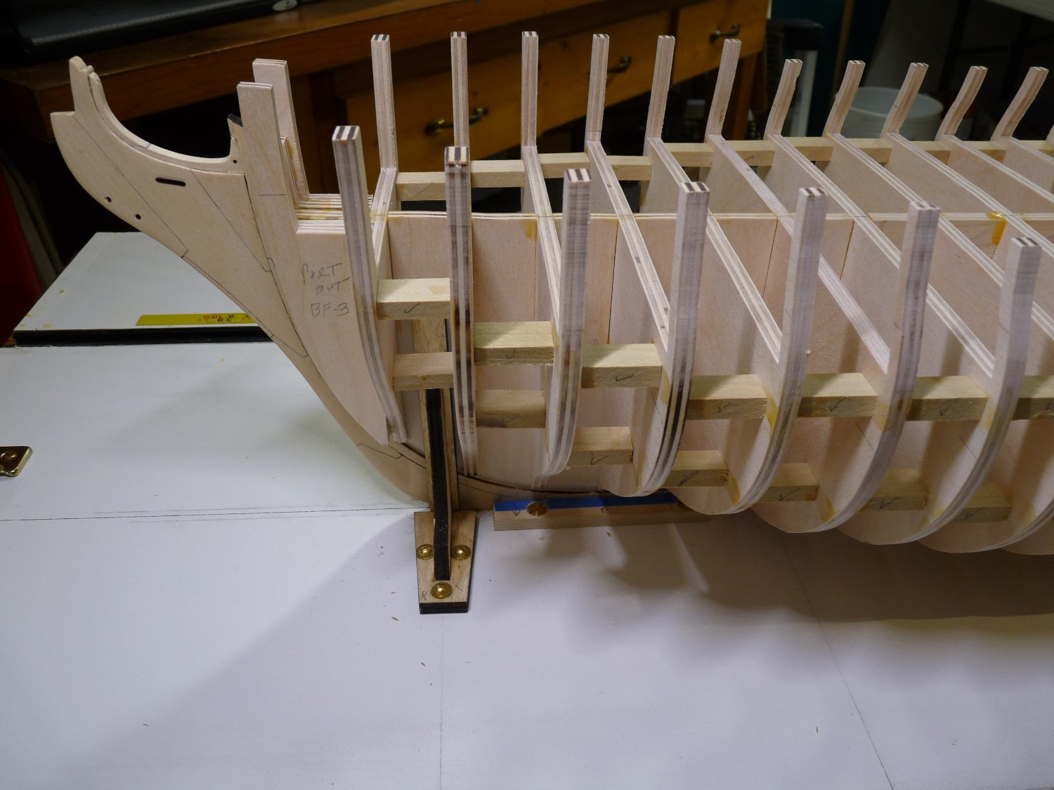
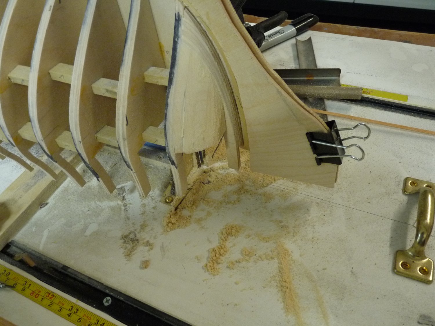
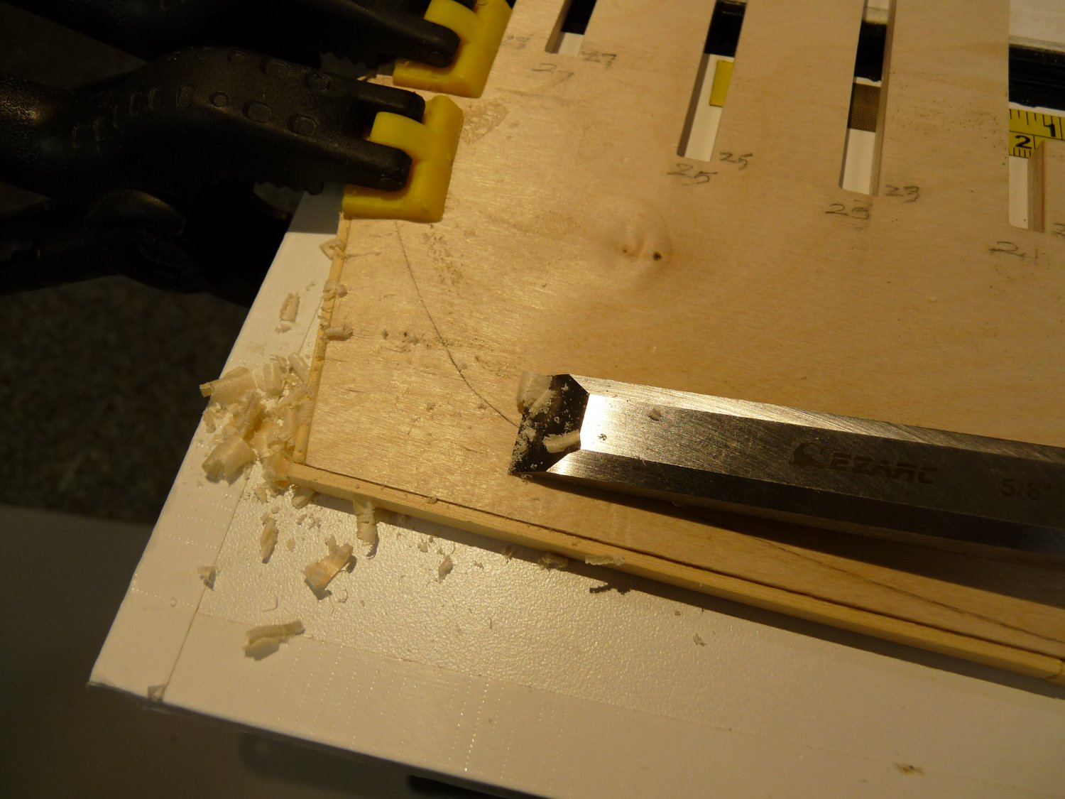
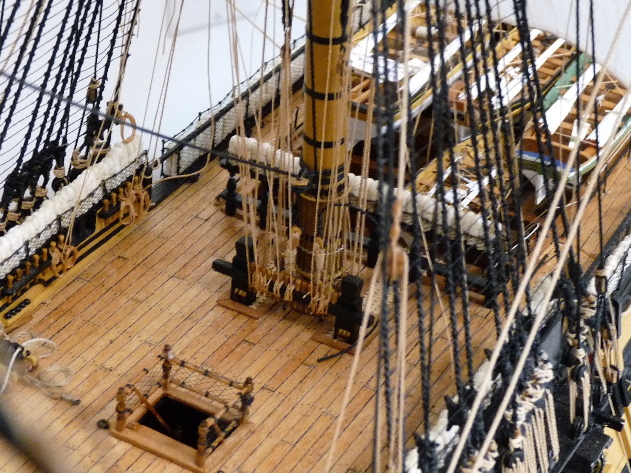
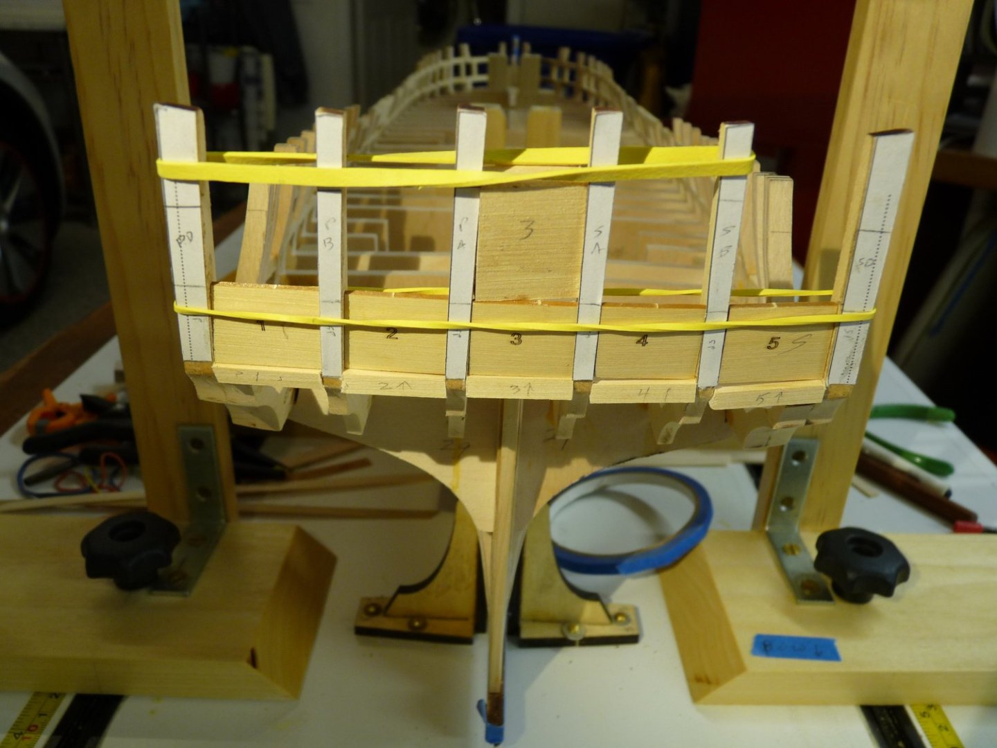
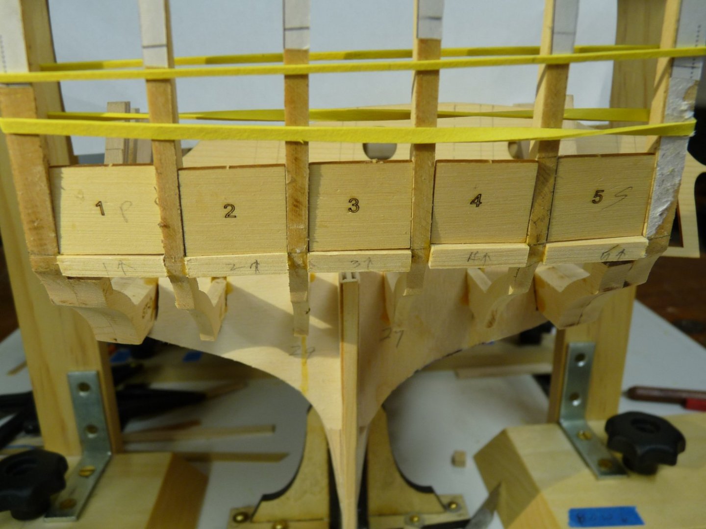
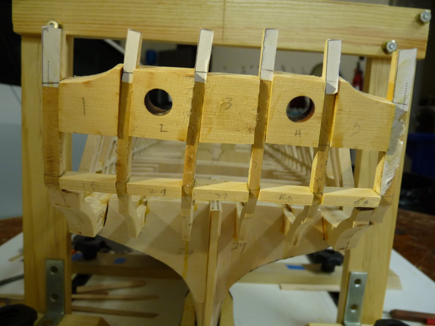
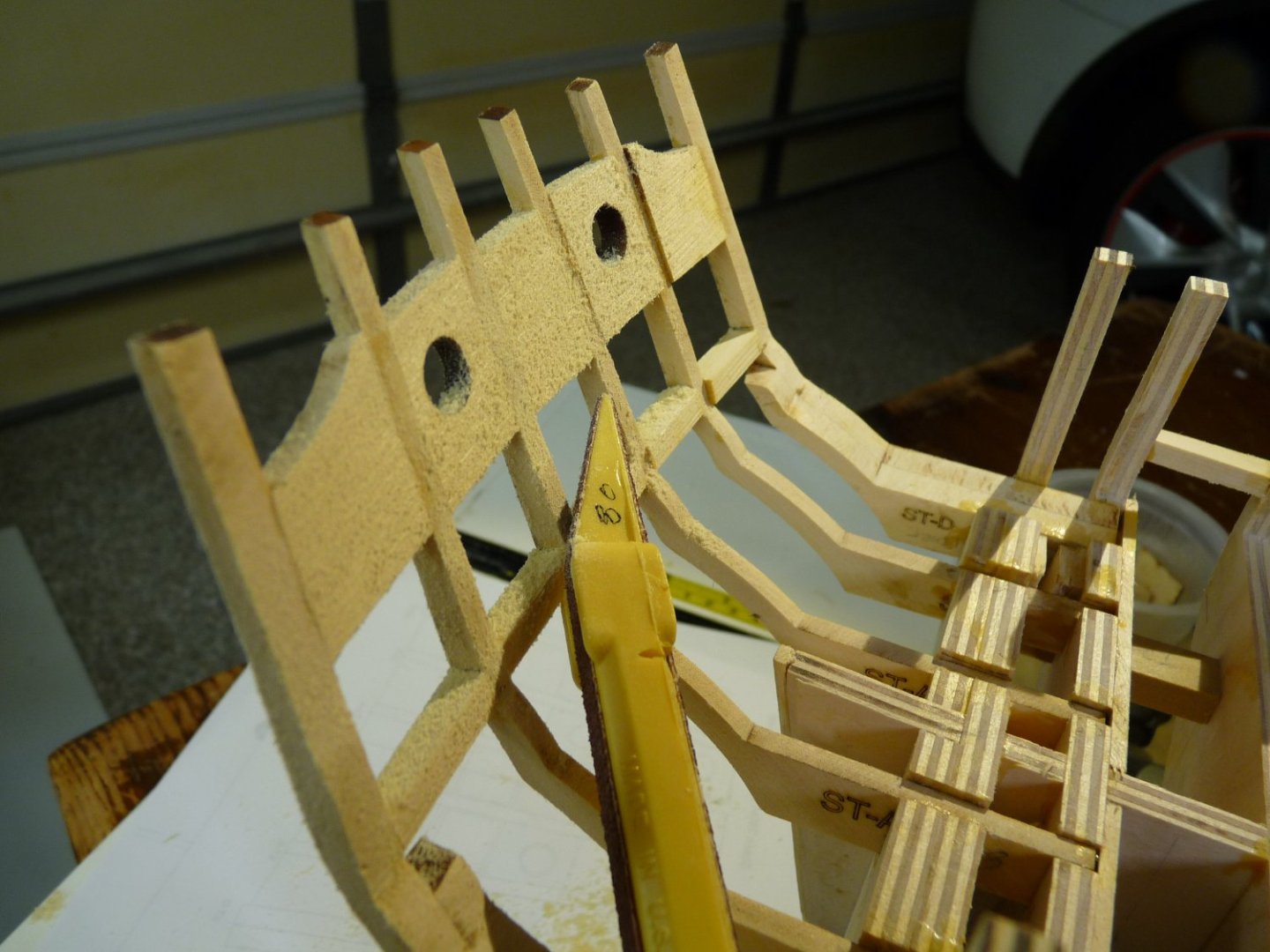
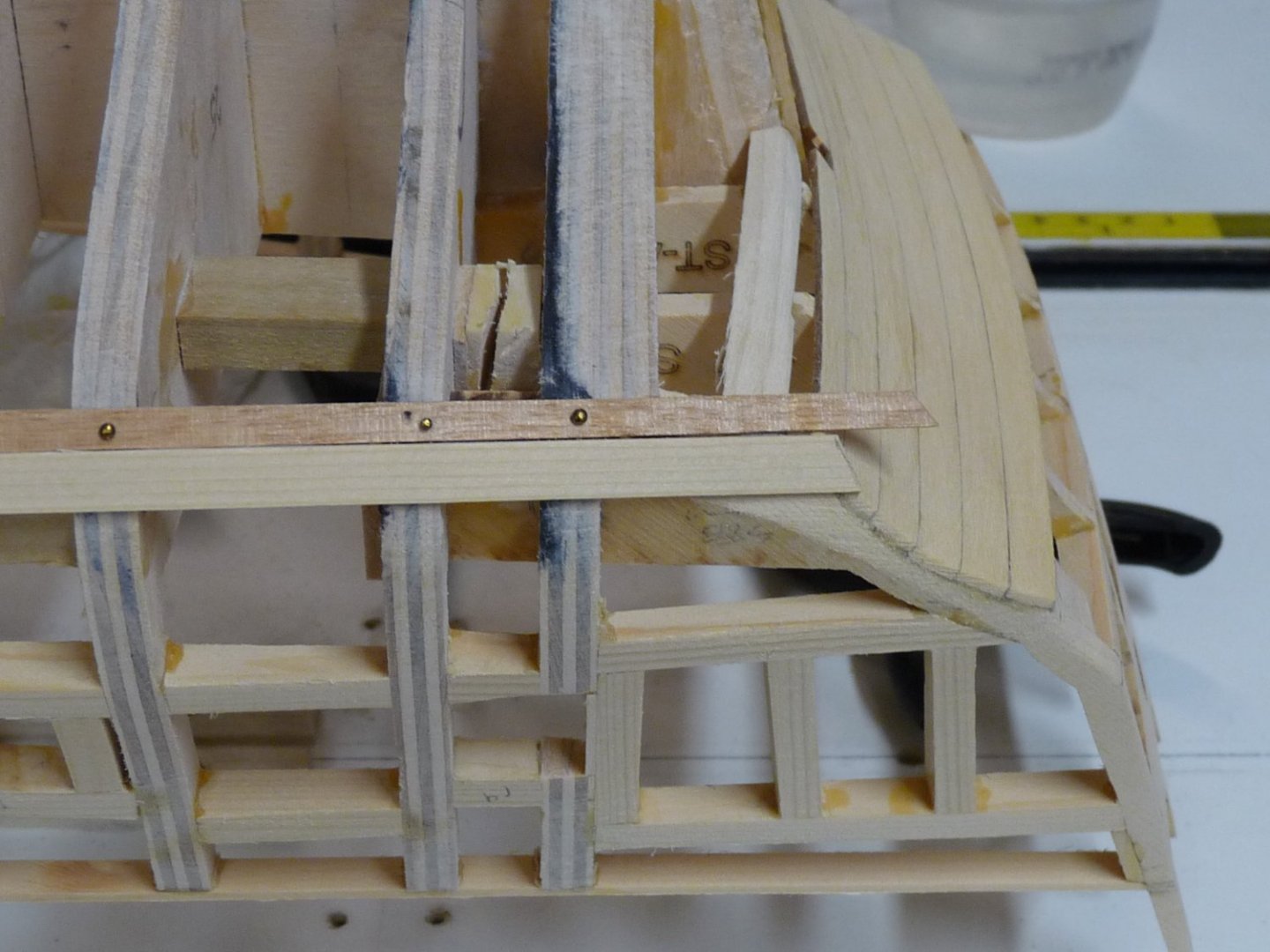
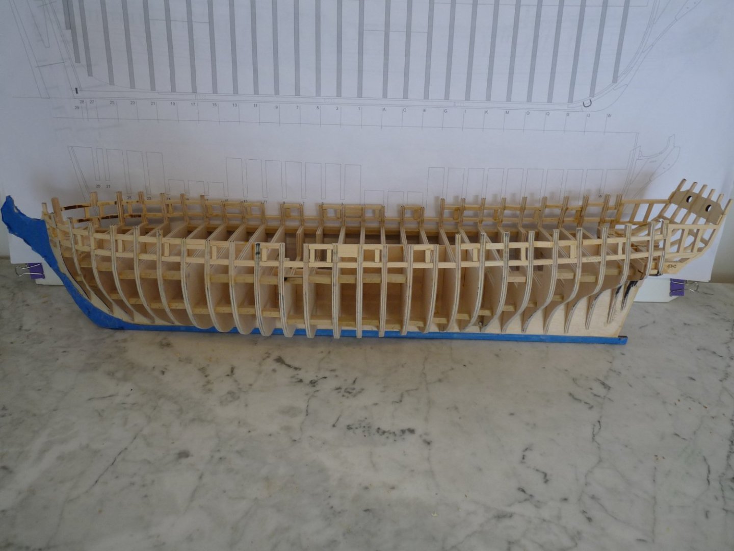
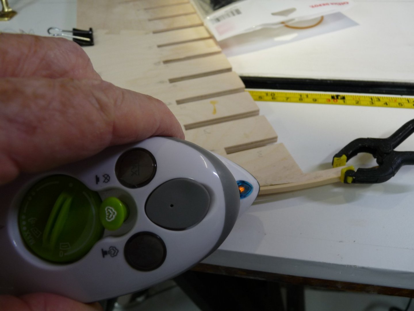
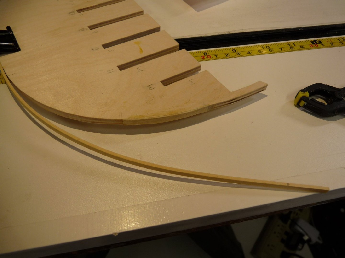
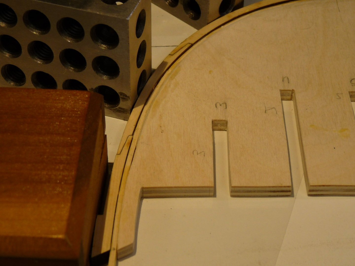
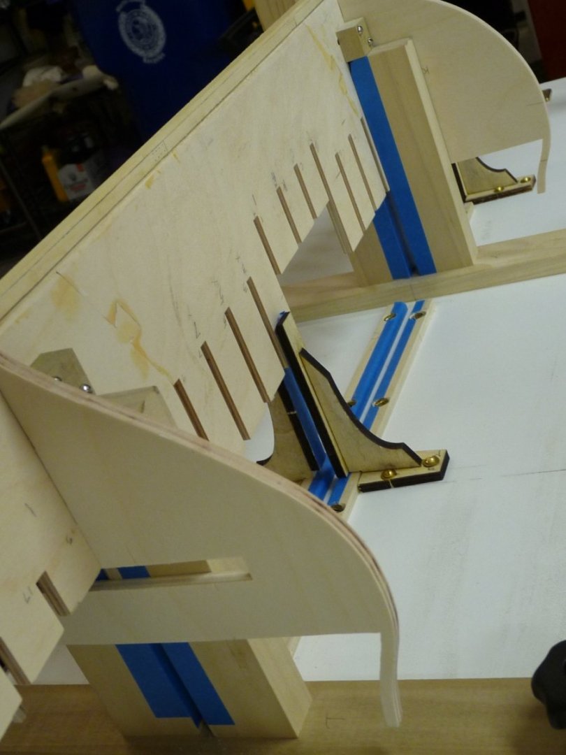
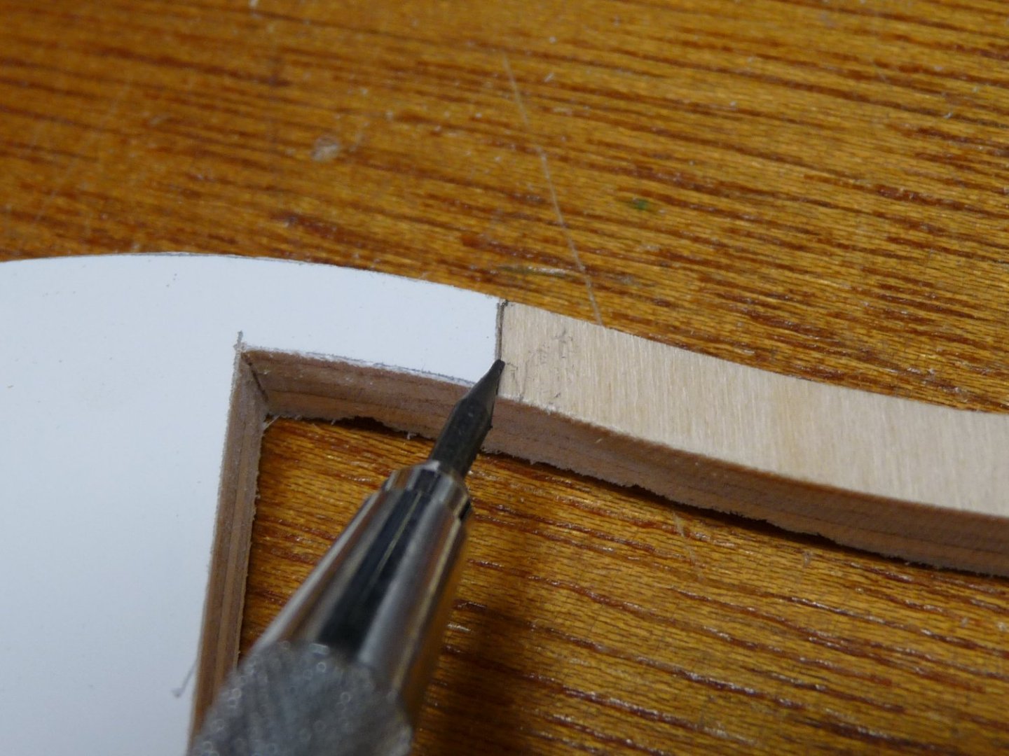
I am actually cheating a little here – I am much further along in the build (have just completed the planking above the wales on the starboard side), and am writing this much after the fact. I have run into many problems along the way that were the result of unclear instructions, my stupidity or a combination of both. I’m going to detail a few of them here in hopes of saving some of the late-comers to the group build some agita. As to the placement of the stern timbers, there is no clear-cut instruction in chapter one or depiction of their placement on the drawings that gives their exact locations. My situation is probably worse than most, since I cut my own bulkheads and the slots for the locations of the stern timbers are probably much less precise that that of the purchased laser-cut ones from Chuck. Mine were a little loose in the slots, which left a lot of play that didn’t allow for clean locations. The fore-and aft, vertical and angular positioning of the six stern timbers is crucial for getting a correct transom and Q gallery construction. Looking at the sheet #3 plans, it appears that the fore-and aft position of the lower projection of the timber has the forward edge flush with the forward face of bulkhead #27. At least that is true for the timber shown on the drawing, but I can’t tell which timber of the six is depicted here, so I presumed that this was true for all of them. It also looks like, from the position on the drawing, that the lower edges of the extensions are seated at the bottoms of the slots (NOT flush with the top face of the bulkheads) in both bulkheads #27, #28 and #29. Any sloppiness in the slots here causes major deviations in the timbers’ locations. There is also a gentle athwartships curvature across the aft faces of the timbers – this is shown on the upper plan vies on Sheet #4, but only at the main deck level. Another gentle curve is found top-to-bottom across the whole transom area. These compound curves make the construction of this whole area very problematic and worthy of a lot of thought before committing to gluing things in place permanently. Then comes the problem of locating the stern window guides, along with the top and bottom sills- all of which have to be correctly beveled. I finally managed to get mine temporarily assembled using rubber bands to hold everything in place, but there was still a lot of motion in the whole assembly. And no real way to make a template or guide to hold everything in its correct place. After getting everything where I thought it was correct, it all had to be taken apart in order to apply the glue in the slots. AARGHHHH. I finally managed to do it, but am afraid that I ended up tiltng the whole assembly a little low on the after end, as things swiveled in the bulkhead slots. No way to fix it now; I’ll try to make corrections down the line as I approach the Q gallery construction. In retrospect, I think I should have used some super thin CA run down into the joints at the bulkheads while the whole assembly was being held together with the rubber bands instead of disassembling it and individually applying TB II to each joint. Before gluing the window sills and lintels in place, I checked the positioning of the transom piece for correctness, making sure that the lower corners were set to the same height and that the angles of the vertical parts of the stern timbers were correct. I then cut and placed the window sill pieces, using the window guides to help locate them. The sill pieces were left proud, more on the outside than on the inside (less convenient access on the inside), to allow for sanding down until they were faired to the transom curvature. The transom filler pieces were then added atop the window guides and sanded fair both inside and out. Next comes the Q gallery door framing, and here I also messed it up pretty well, not realizing the need to locate these pieces carefully. I just eyeballed them as I thought that they were only structural members. It wasn’t until much later, as I was planking the upper hull above the wales, that I realized that the bottom and top members formed the sills and lintels for the doors in to the head areas in the galleries. It turns out to be important that these pieces are parallel to the planking that goes on the outer hull, which is in turn parallel to the run of the sheer which is determined by the placement of the wale strakes. If I had realized this, and were doing it again, I would have laid out the run of the curvature of the top wale at the stern area, counted the number of planking strakes above the wale to the top of the sill and added up this distance for the aggregate of the planking. Then I would have cut a cardboard template to this height to use as a guide to locate the tops of the sill pieces, then the lintels would have been placed at the proper distance above and parallel to the sills, as measured on the plans. The angles of the two uprights could have then also been measured on the plans and installed parallel to one another between the sills and the lintels. My starboard side opening turned out close enough that I think that I can shim and trim things up later on, but my port side is far enough out that it will need to be redone. Next, Chapter One instructions call for the placement of the after hance piece, followed by the addition of an upper rail on the quarterdeck that will be used as a guide to fair the outer hull in that area. I actually ran a temporary batten as a guide to have a nice curvature to the rail between the hance piece and the transom, while at the same time trying to establish the intersection point of the rail at the face of the transom. This dimension was measured off the plans, but the intersection was quite a bit too high (2-3 mm) on the model, as the whole transom assembly had drooped a bit as described above. This area may now need some corrective measures as I get around to working on the upper transom. The tops of the BH extensions were then trimmed, the rail put in place and the hance piece installed. It turns out that adding the hance pieces and this upper rail at this time was a bad idea, one that caused more headaches later in the build. My advice is to add neither the hance pieces nor those rails at this point in the build. A temporary scrap strip can be added on the quarterdeck to aid in fairing the outsides of the bulkhead extensions in that area, but should not be applied permanently. The reason for this is the same as the one for the location of the door sills; the rail atop the bulkhead extensions and the tops of the hance pieces need to be exactly parallel to the sweep of the sheer, and also at the proper height (some integral number of planks) above it. This can best be done later in the build. I have had the hance pieces installed and removed four times now before it became clear on how best to install them. I’ll describe this in more detail in a later post, but basically it makes more sense to first plank the outer hull in the quarterdeck area - this planking will automatically parallel the sheer along the hull, Then the tops of the BH extensions can be carefully trimmed to their exact height (less the thickness of the Q deck rail) before the last plank is put in place. Note that the top plank is flush with the rail; the rail does NOT extend over the edge of the upper plank. A small cross-sectional view on the plans would have made this very clear. , The rail was then installed and the after hance piece put in its proper height and attitude (note some tumblehome here). This will in turn dictate the locations for the forward hance pieces. All the work described above was done last October; after a lot of rework in removing planking and hance pieces on the starboard side, today (Jan) the model with its corrected starboard Q deck rail and hance pieces looks like this. Note the Q deck rail and planking is flush and parallel to the wales. The opposite side (port) still has not been remediated – the rail need to be removed and replaced, and the hance piece properly located. I will be posting some more retroactive prose at a later time for the intervening work. Another item that is completely missing from the instructions and plans is the need for athwartship members near the stern to receive the ends of the middle hull planking as it gets terminated at the bottom of the lower counter. The exceptionally curved ends of these planks need support as they approach the transverse planking of the lower counter. These members are called “wing transoms” and are not described either in the construction chapters or are they shown on the plans. However, if you look at some of the members’ build logs, they can be clearly seen. Chuck’s wing transoms are shown on his log in the 1st photo on Page 5. I had real problems envisioning the termination of the hull planking in this area until I realized that wing transoms would define and support the planks here. After adding the wing transoms, I then could proceed with confidence in fairing the hull in the stern area now that I could envision how these planks terminated and how they flowed into the counter. Following fairing, I planked the lower counter as per Chuck’s instructions using his laser-cut strips. Here I'm in the process of establishing the run of the wales. After the bollards were added at the prow, it was on to Chapter 2 and installing the 1st layer of wales. We’ll talk about this next time. Thanks for looking, Ted


-
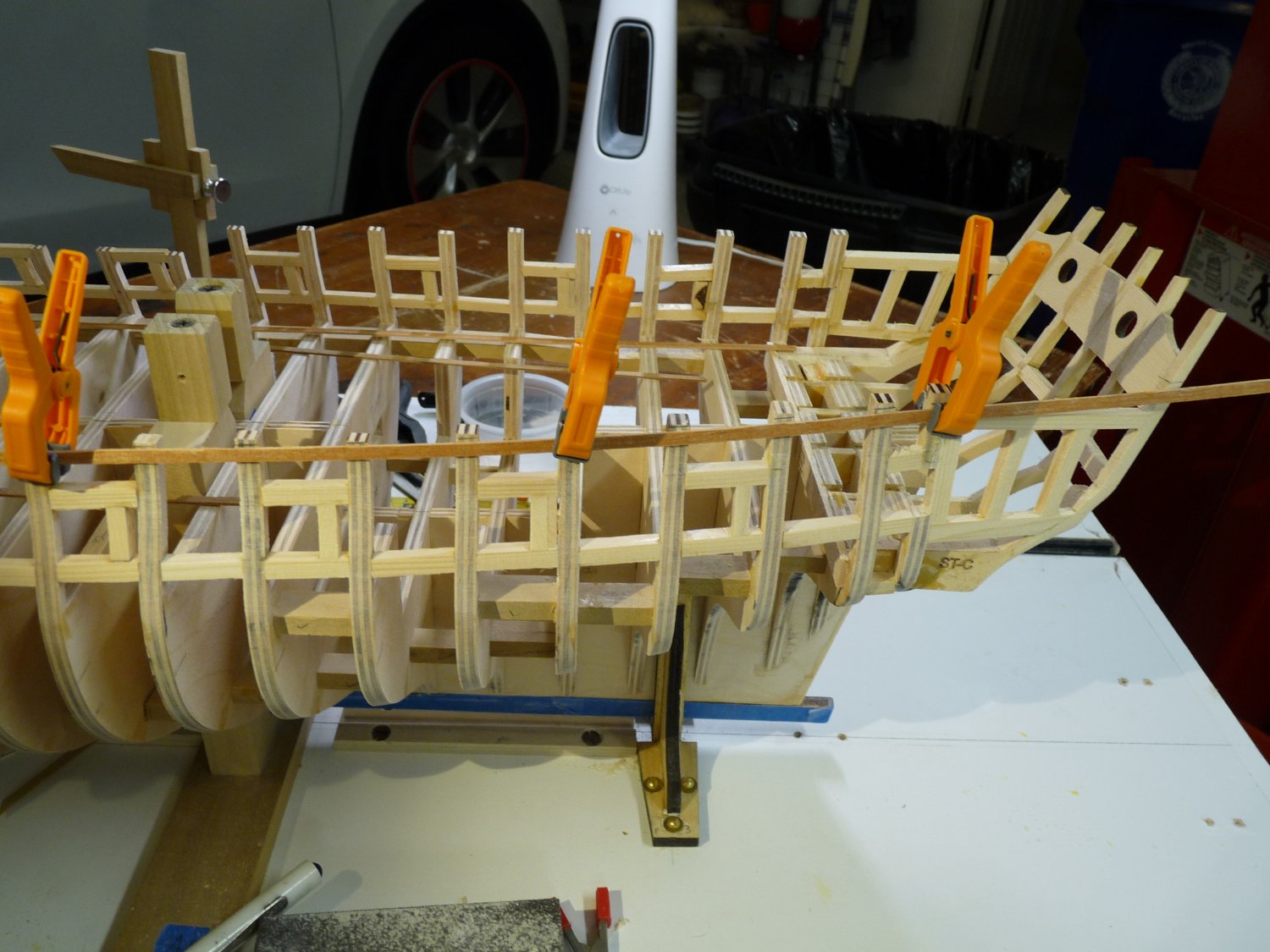
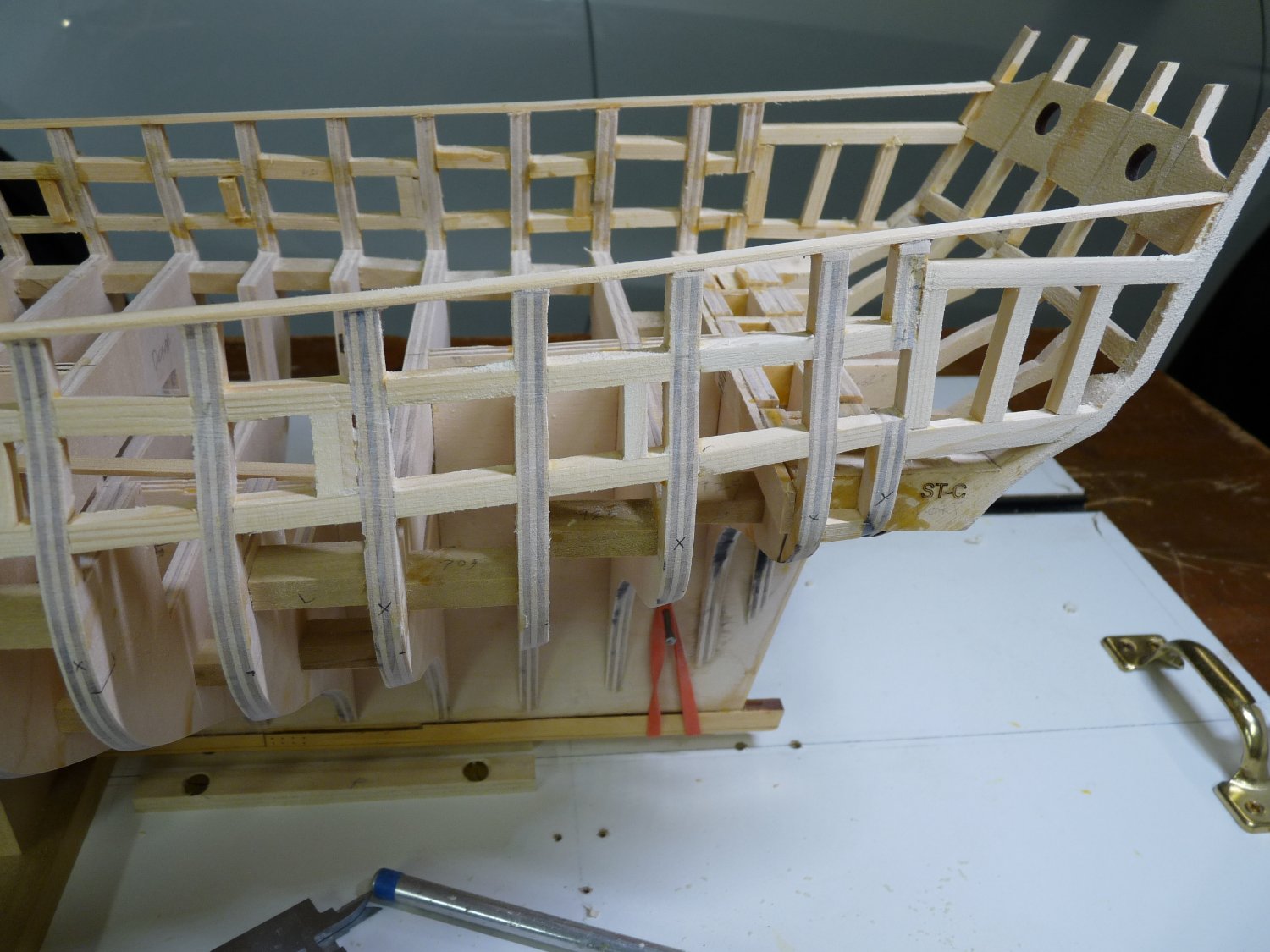
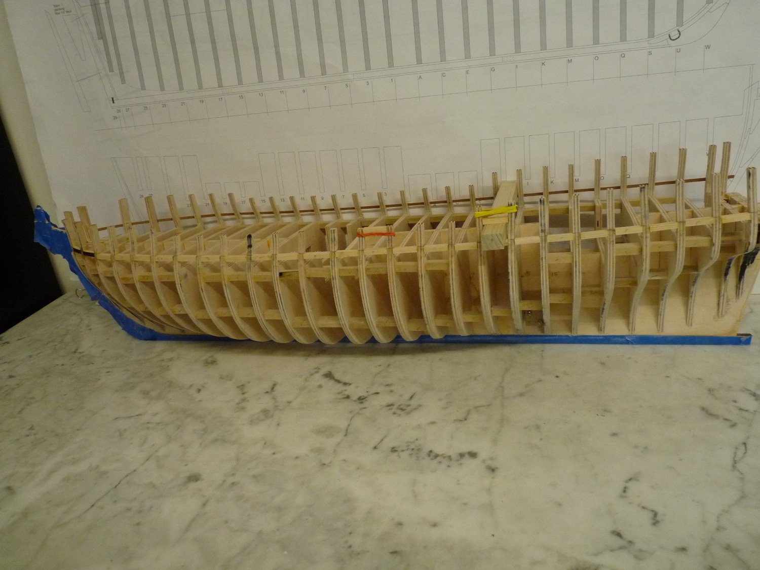
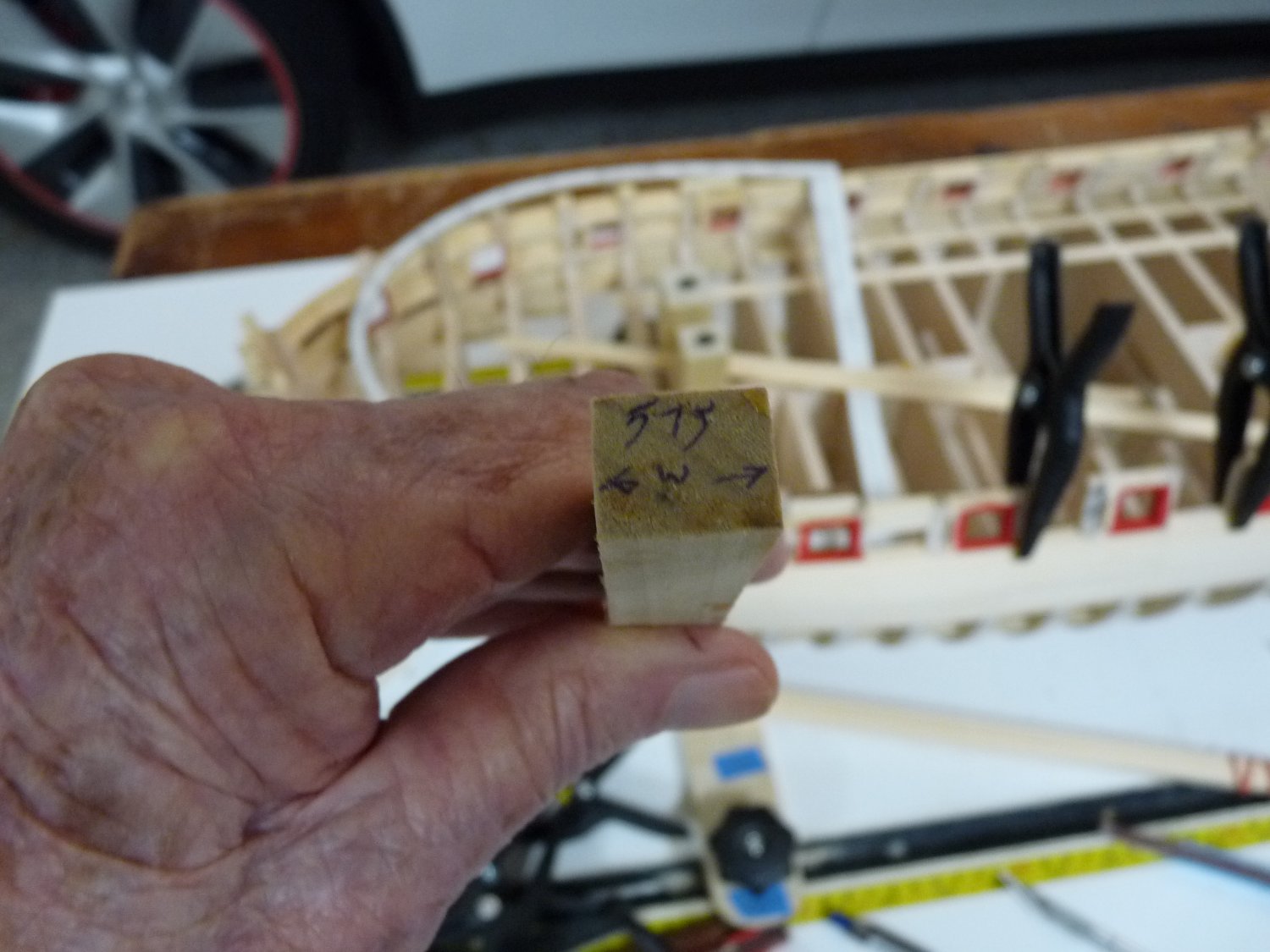
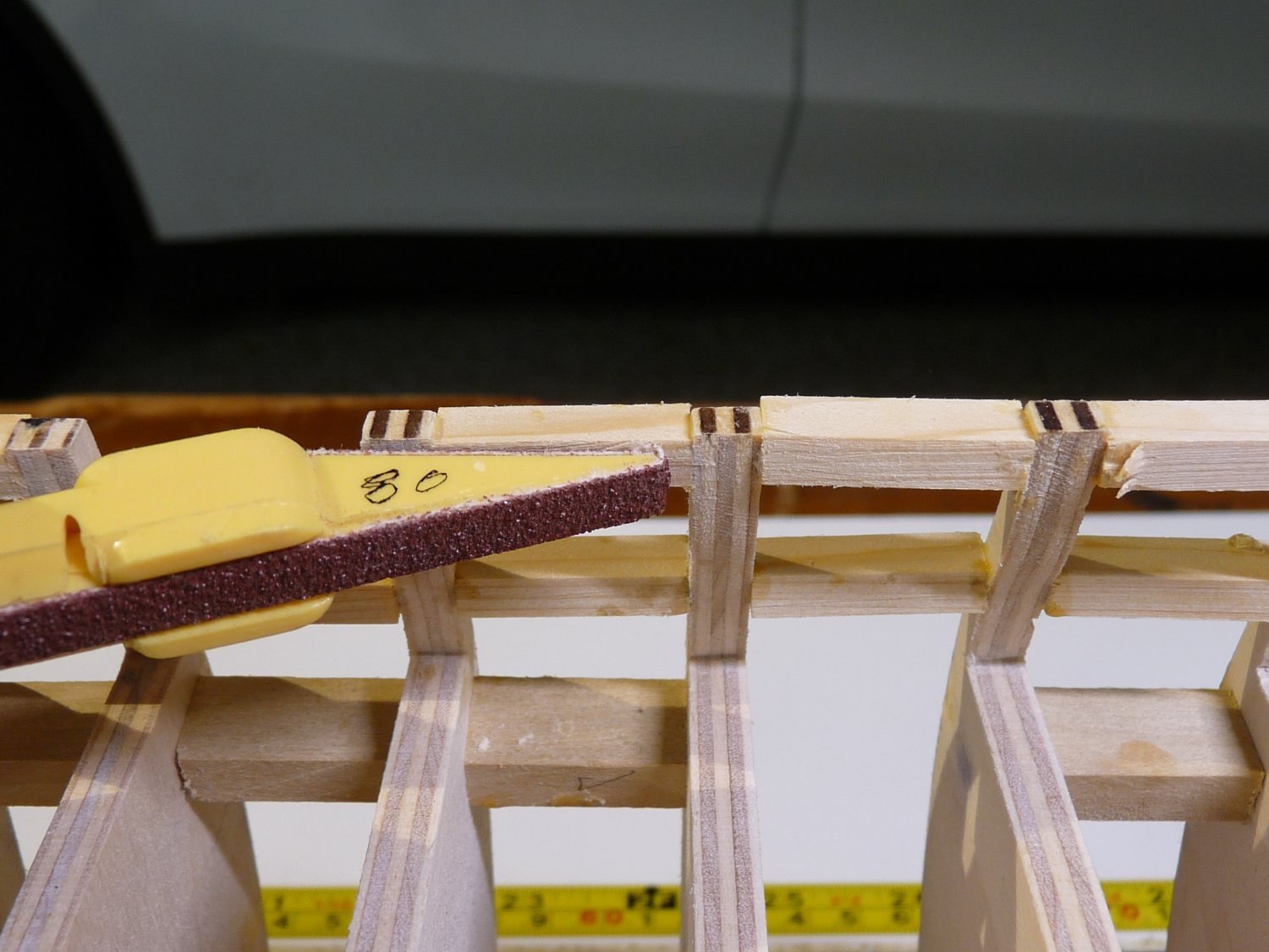
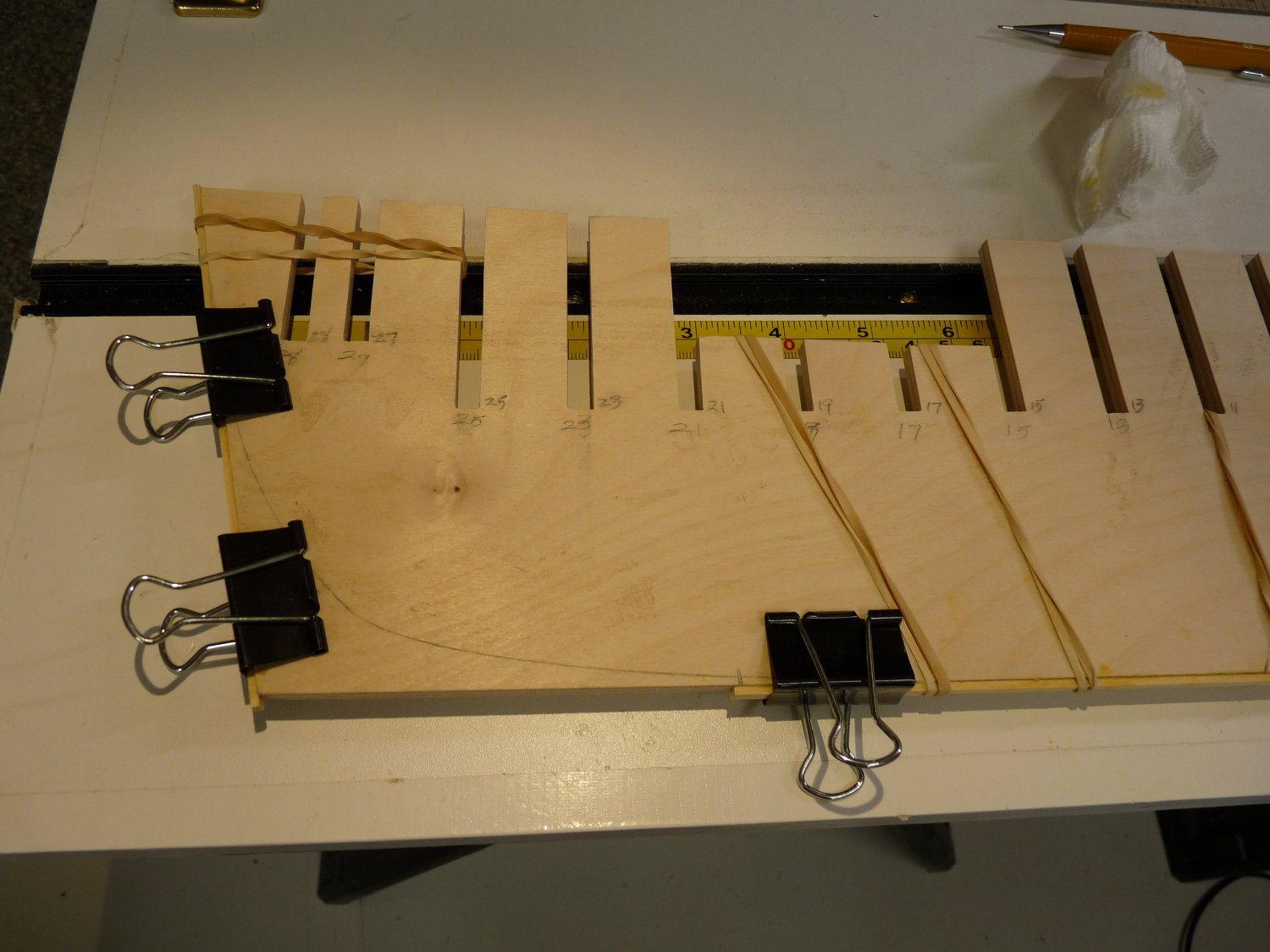
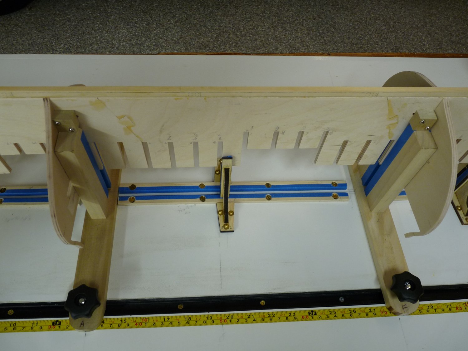
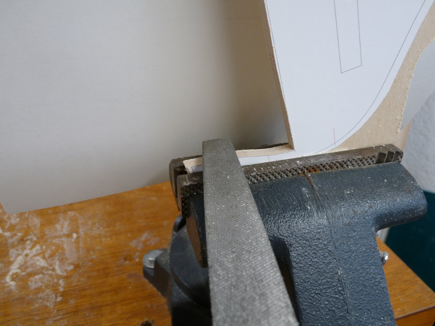
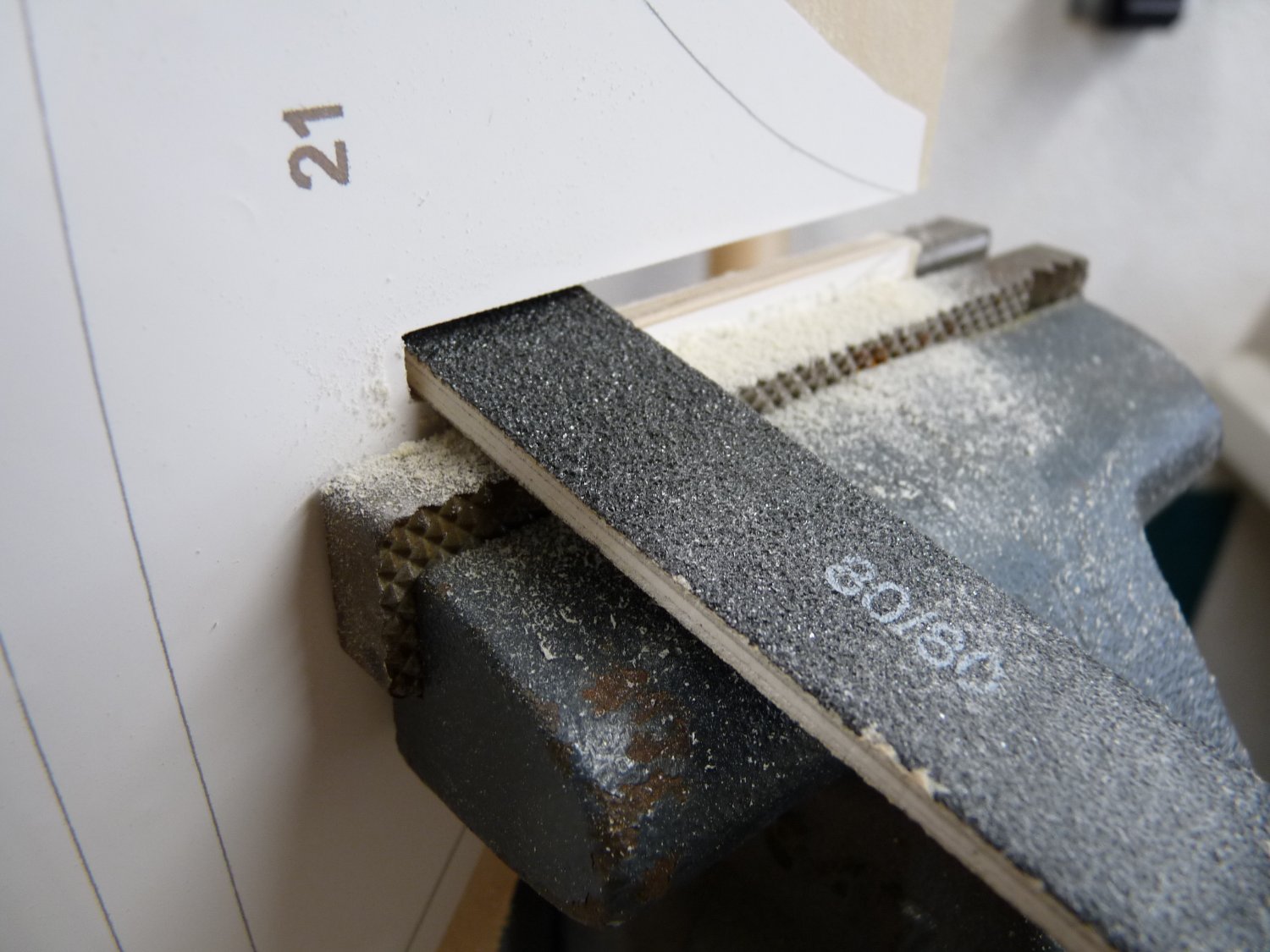
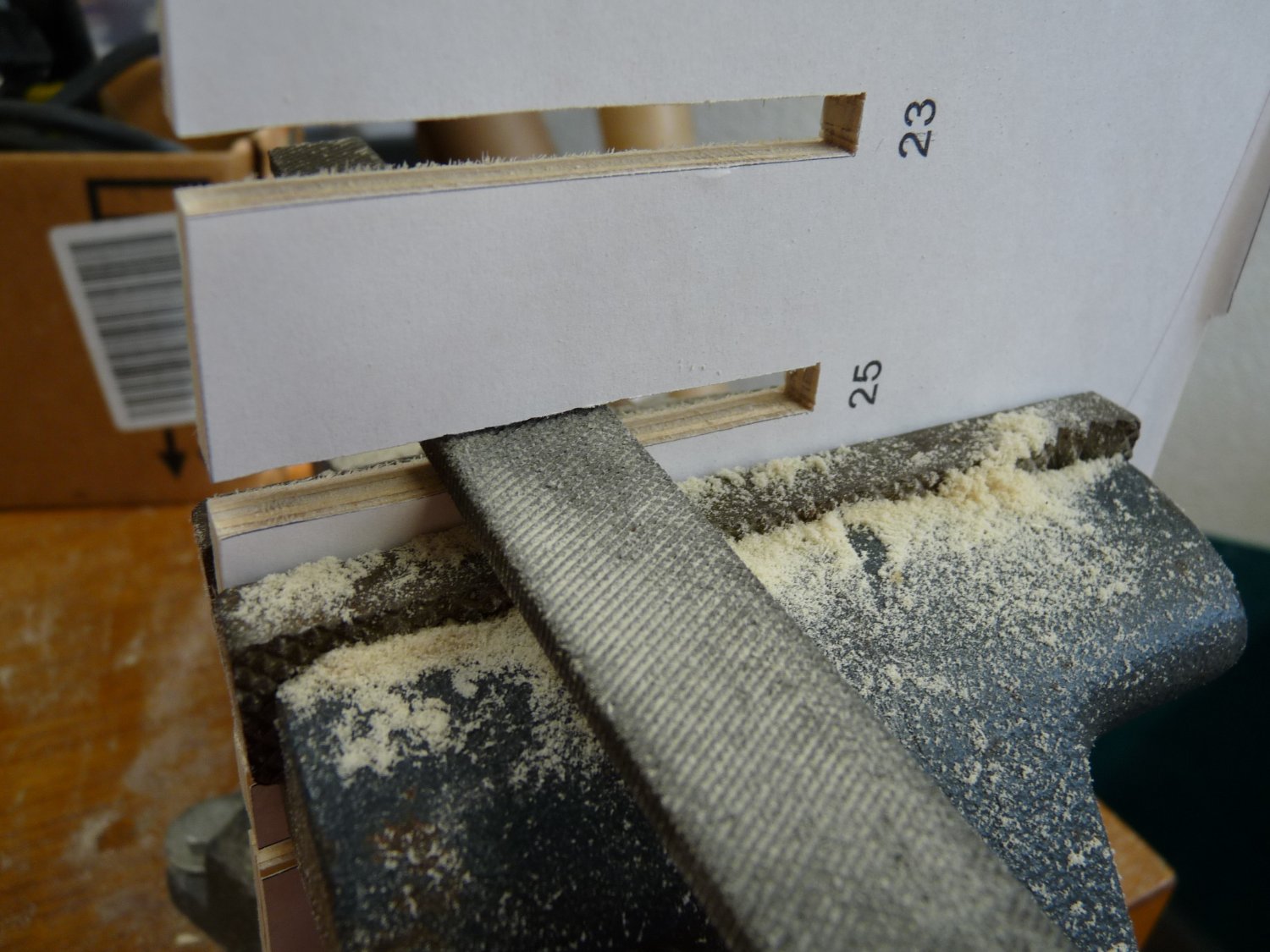
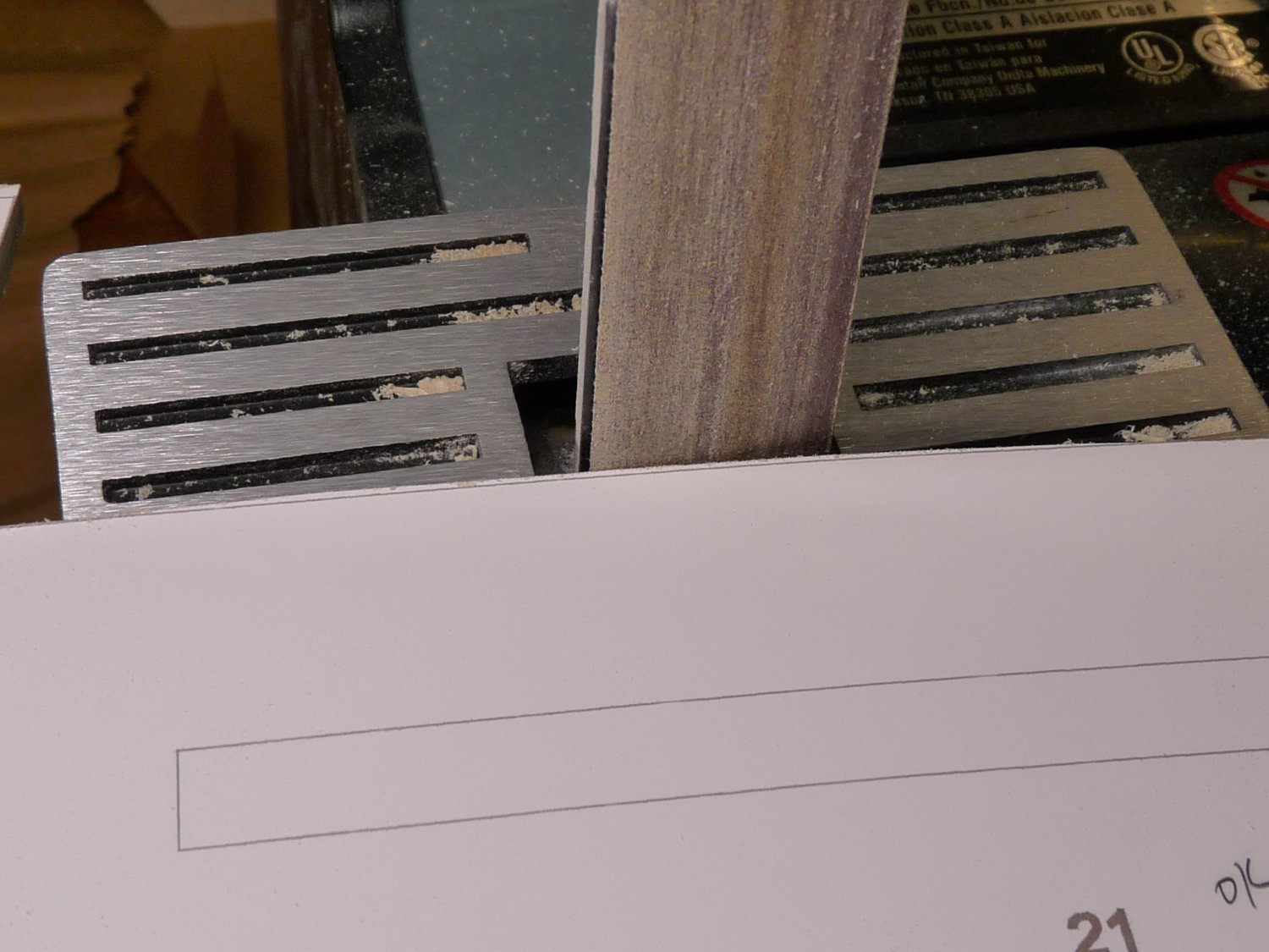
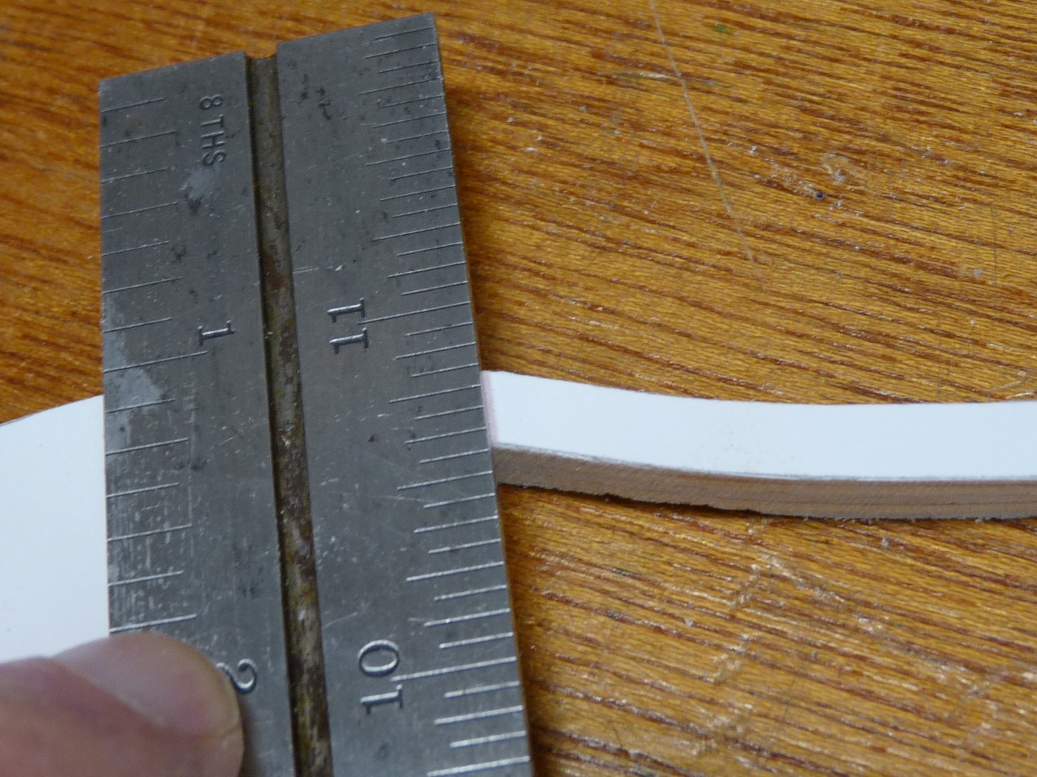
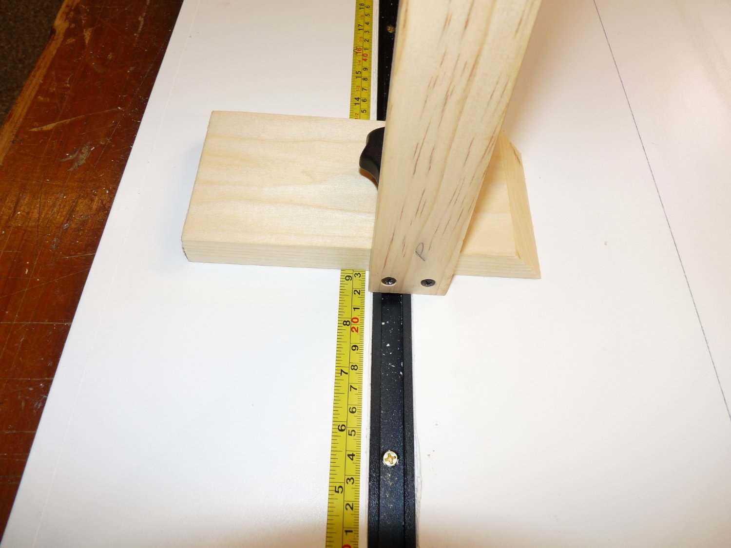
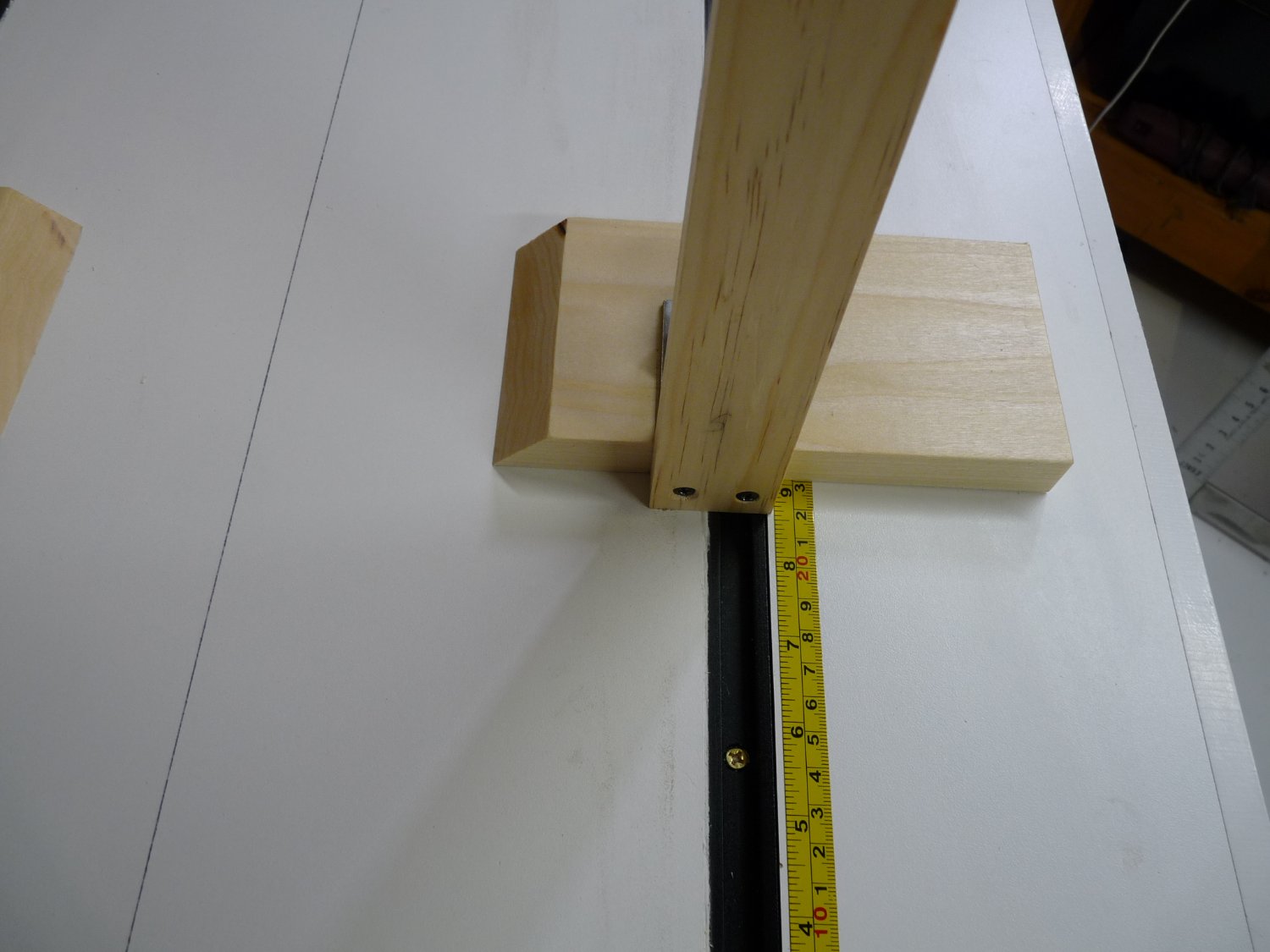
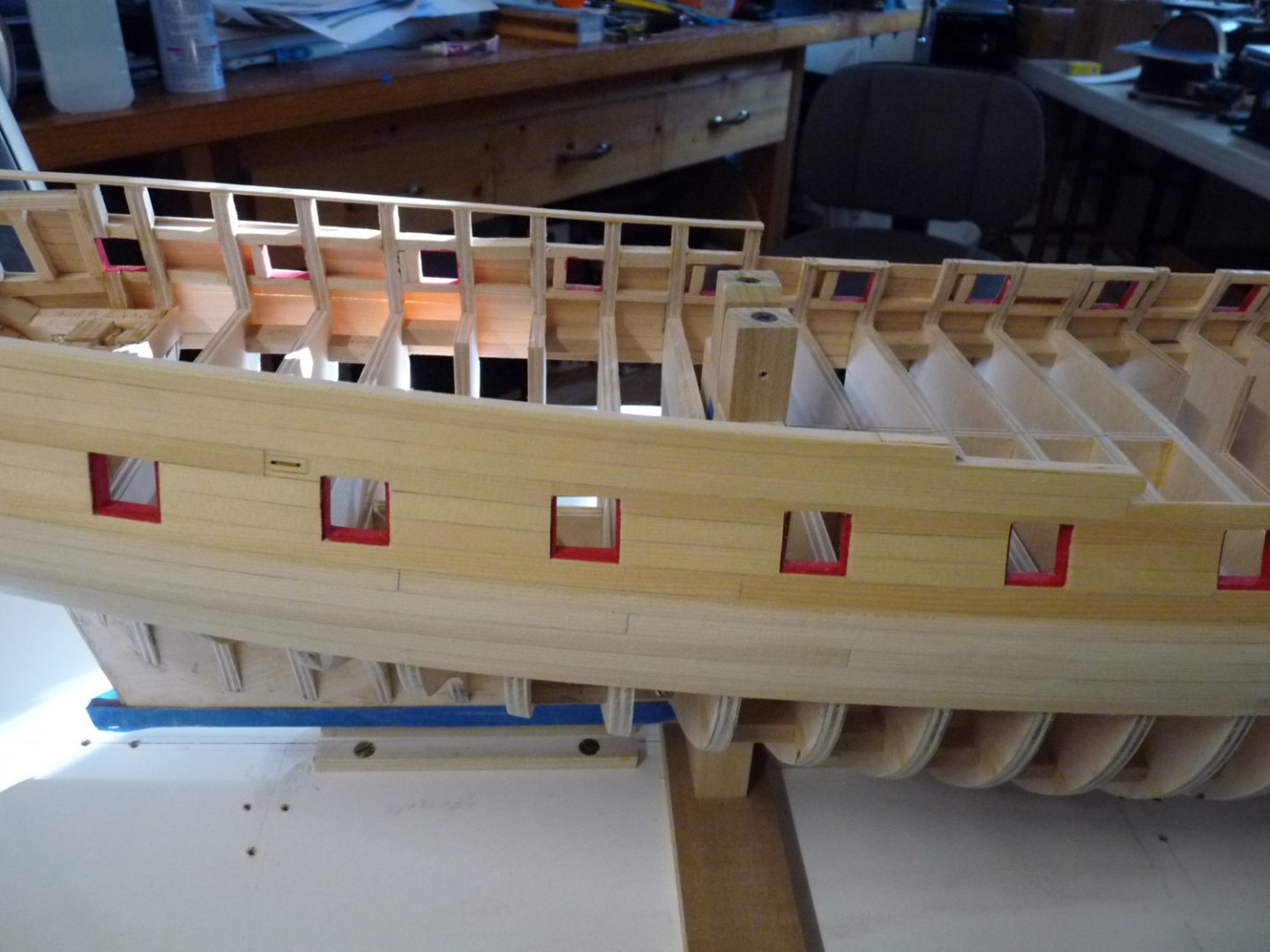
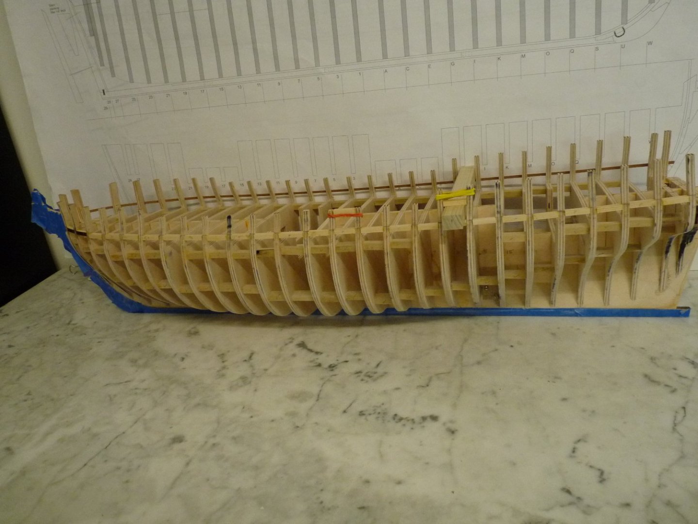
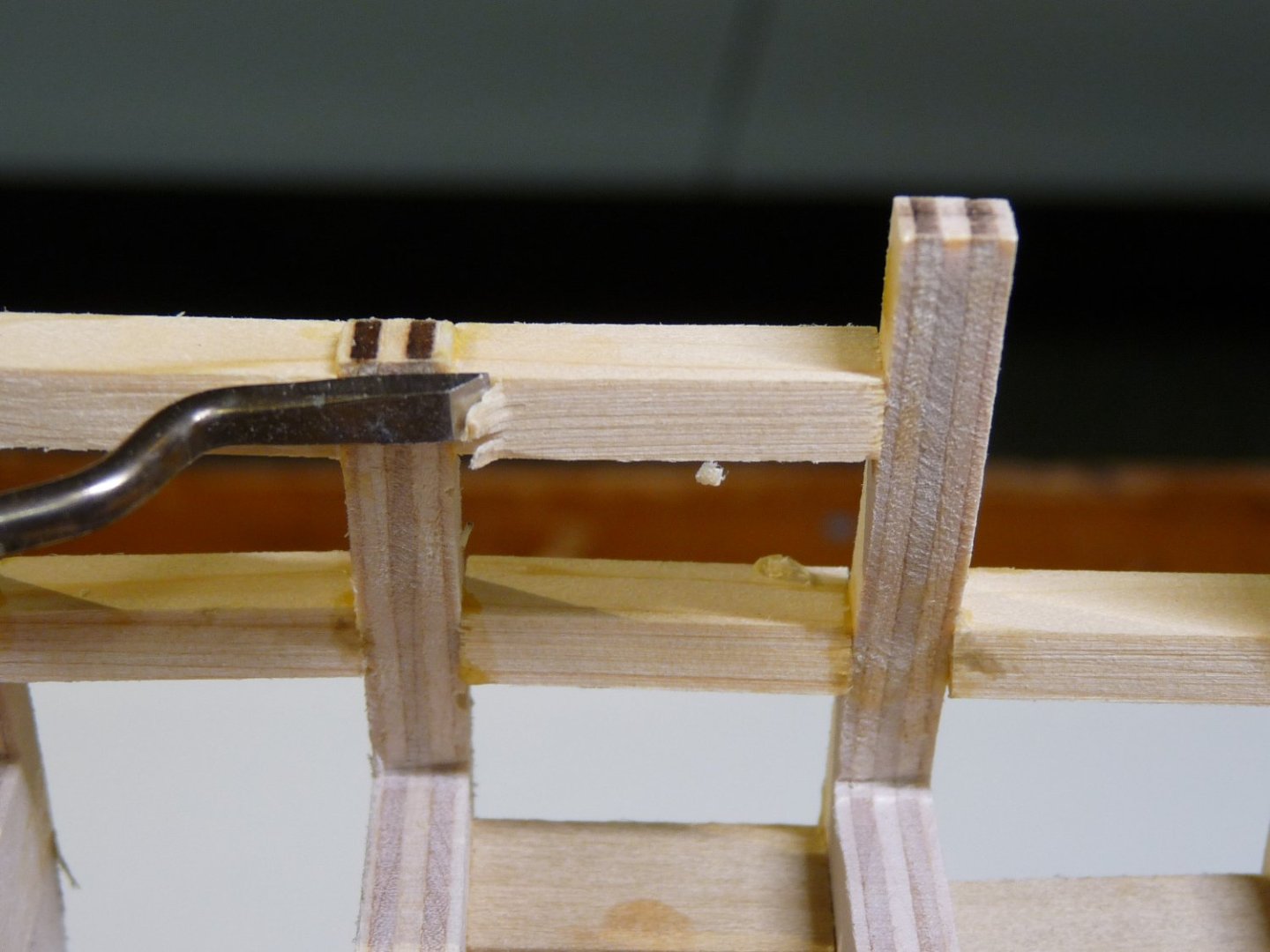
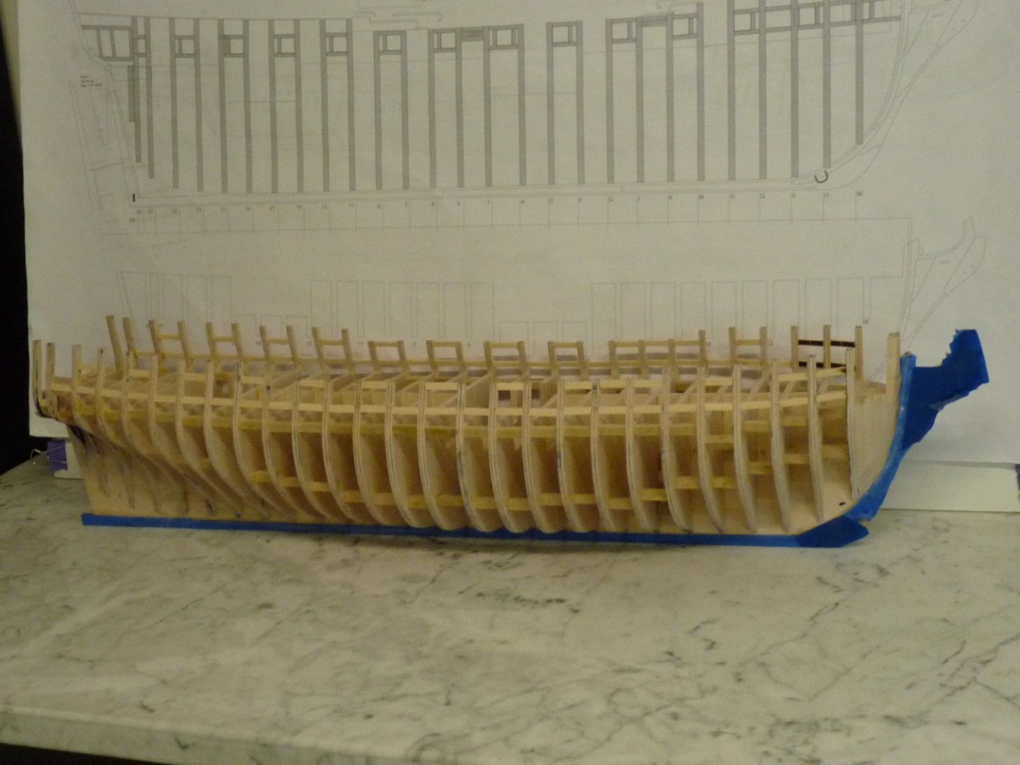
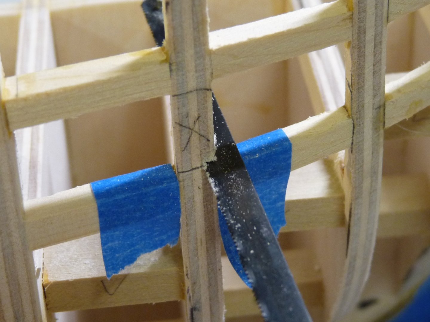
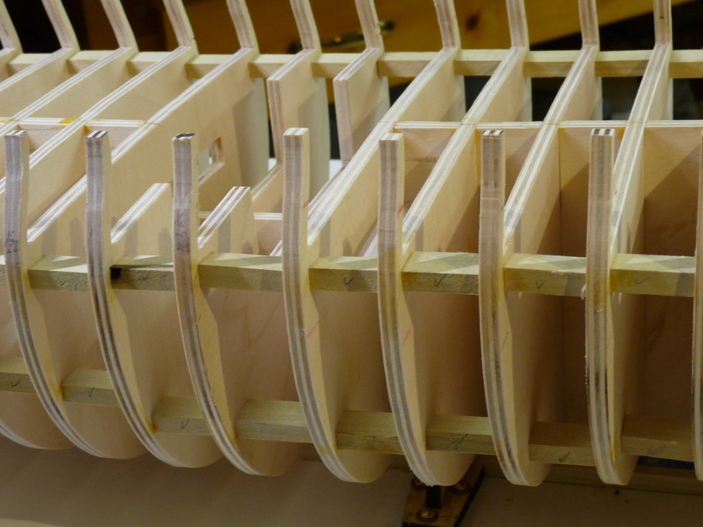
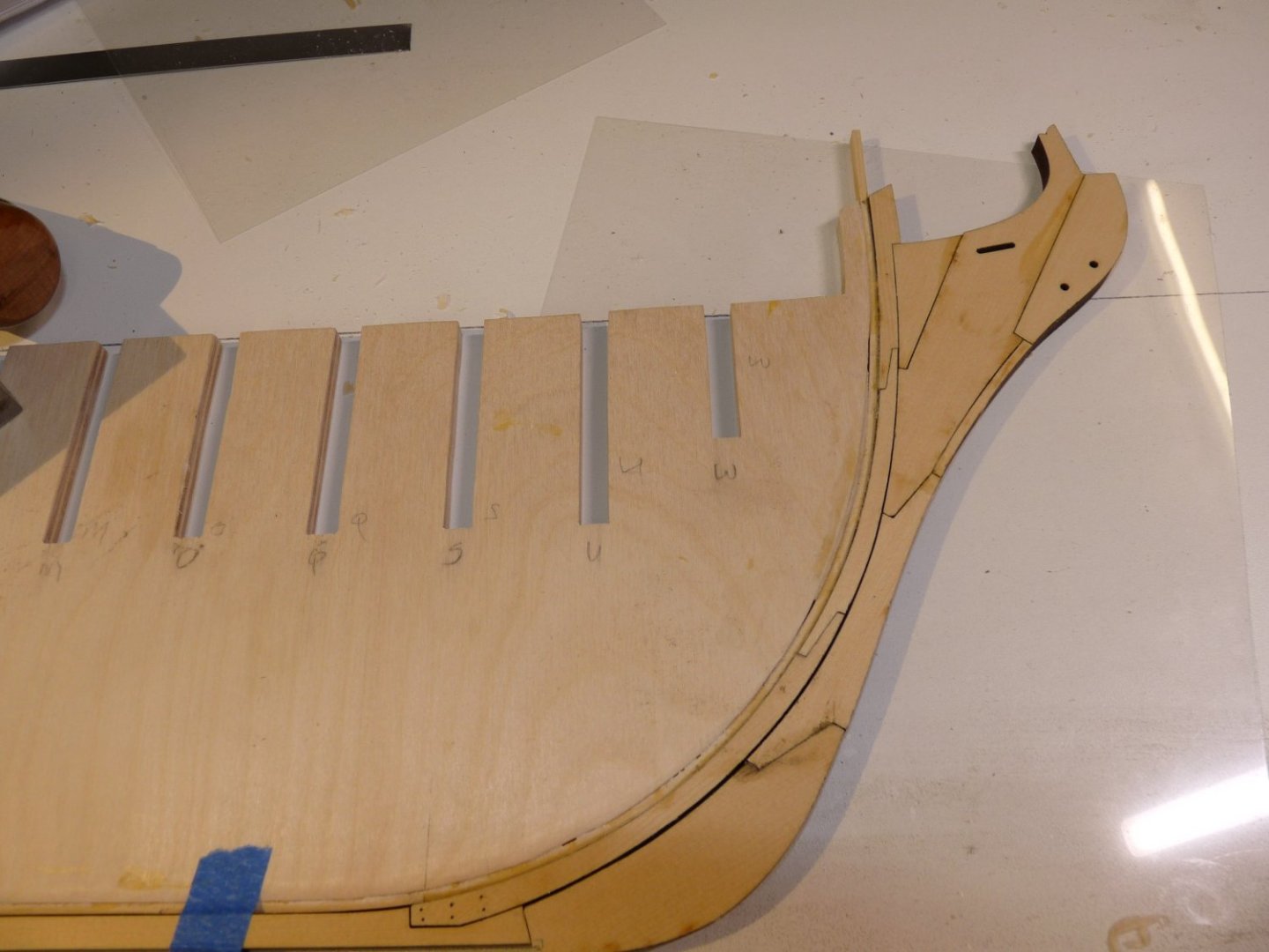
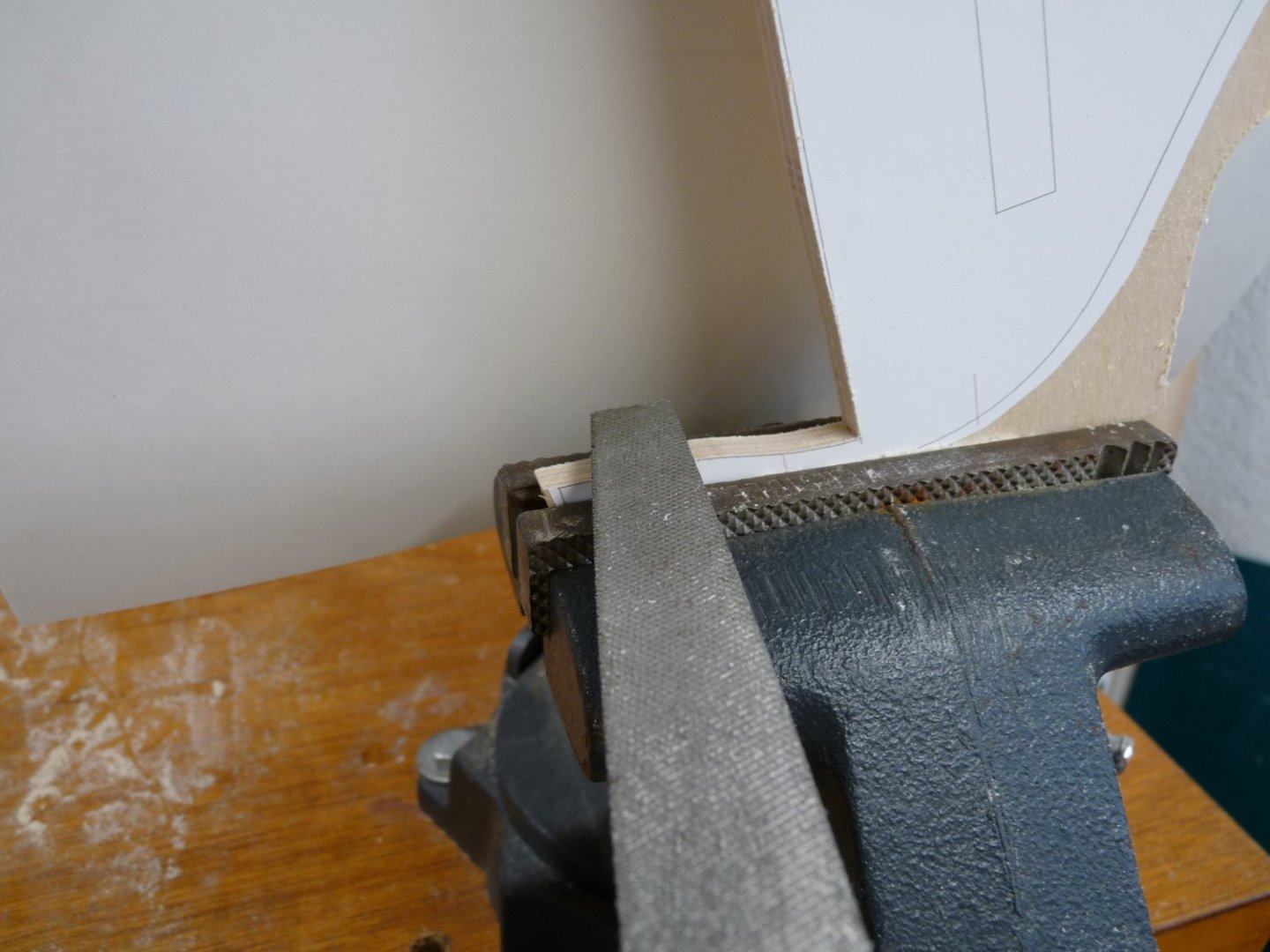
My last post was about 17 weeks ago, and I stated then that I was about 75% thru with the hull fairing. Not true!! I have spent a lot more time fairing, and learning as I went. I have long neglected posting here, and am now trying to play catch-up. I am actually now (late Dec) doing some planking above the wales and other work, but will continue adding some belated info here for a while until I get caught up. In the meantime, I was concentrating on finding a fair line on each side of the hull for the tops of the lower gunport sills. As per Chuck, I started with a batten aligned with his bulkhead tick marks on the starboard side, and then tweaked the placement until I got a nice clean sweep for the run of the sills, tacking the batten in place with a few small nails on the starboard side. I didn’t take many pics during this process, but in this later shot you can see the batten in place on the far side of the hull. Then using my height gage, I transferred the markings of the top of the batten at each bulkhead over to the port side, leaving the starboard side batten in place. I made a gage block of sorts from a piece of scrap poplar. The bulkheads are nominally placed on 1-1/8” centers, so less the bulkhead thicknesses they are spaced 7/8” (.875”) apart. From the drawing, I measured the gunport widths at midships to be about 9/16”, and the heights are about the same. Near midships the ports are roughly square, but as the sheer rises both forward and aft, they become more trapezoidal. The gage block was made with a width of .575”, which will be used to hold the port widths and heights to that uniform dimension. To accommodate the varying differences in port height due to the sheer rise and deviation from being square, the other gage dimension was held to about ½” (.500”) so it will fit in the opening. The length of the gage was made to be a little more than the beam width, about 9-1/2. The height and length dimensions of the gage are not critical, only that the width is the desired dimension for the gunport width and height, the bottom of the block is flat and true. Then, placing the block so it rests on the top of the batten on the starboard side, I started adding the gunport sills on the port side, lining up the upper edges of the sills with the tick marks that had been placed using the height gage. Care was taken to make sure that the tops of sills were aligned along the sweep of the sheer, registered with the tick marks. After trimming each sill piece to exact length and angle using my disc sander, I applied some TB II to the joints and put it roughly in place. The tricky part, and where the gage block comes in, is ensuring that the top edges of the sills lie in the same plane on both sides of the hull. After the sill was in place, I laid the gage block across the hull, resting on the batten on the far side to determine the plane of the sill. Then, after making sure that the top of the sill piece was aligned with the sheer tick marks, it was rotated along its long axis until it laid flat against the bottom of the gage block – this ensured that the port and starboard sills were true to each other and in the same plane. Then a rubber band between the bulkhead extensions served as a clamp while the glue dried. 3 BTW, I am going to include some details and observations that are meant to help newer modellers wend their way through the Winnie build. You more experienced modellers can just skip over these details. The Chapter One instructions call for the gunport sills and lintels to be ¼” x 3/16” material. It seems obvious that the ¼” dimension is the height of the sills, not the width, but this is not specified anywhere. This can be verified by a quick measurement off the large plan sheet. Note that the 3/16” width is somewhat larger than the width of the bulkhead extensions; it will be beneficial to place them with any excess wood overhanging on the outside of the hull rather than on the inside, which will make the later fairing of the inner bulwarks a little easier. Much later on , both the interiors of the bulkhead extensions and the gunport pieces will be faired and reduced in thickness on the inboard side. After all the port sills are in place, remove the batten from the starboard side, and using the already installed port sills to bank the gage block on, add the starboard gunport sills as before. After they are in place, the lintels (tops of the gunport openings) can be installed on both sides using the .575” dimension of the gage block to locate the height, as before. Then using a small chisel and sanding blocks, I roughly faired both the inside and outside of all the sills and lintels. The result looked like this. 2 Now all the gunport side timbers can be added. Note that except for ports #1 & #2 (counting from the bow), the middle opening (#7) and the furthermost aft (#13), one side of each gunport opening is formed by a surface of a bulkhead, which is vertical, i.e. perpendicular to the keel. For ports #6 thru #3 going forward, that surface is the forward face of the bulkhead that is to the aft of the port, and for #8 thru #13 going aft, it is the after side of a bulkhead. Ports #1, 2 and 14 all must be treated differently by removing part of a bulkhead extension, and the center one( #7) has side timbers added on both the fore and aft sides of the opening. Use the gage block to locate the side timbers, ensuring that they are parallel to the bulkhead surfaces, and with the uniform .575” dimension. As the sheer sweeps forward and aft, the port openings turn more trapezoidal, and care must be taken with the gage block to ensure that the side timbers are also perpendicular to the keel (parallel to the bulkhead surface), and that they are not necessarily perpendicular to the sills and lintels. To try to avoid confusion, I placed small pieces of tape where the uprights need to go. For openings #1, 2 and 14, after removing the sections of bulkhead extensions, use the gage block to locate the sides of the openings, while noting that the side faces of the side timbers also angle in toward the centerline of the model (are not parallel to these bulkhead faces). Here is a shot after the gunport uprights have been placed. Next time we’ll talk about the difficulties in locating the stern framing timbers. Cheers, Ted


-
Chuck, absolutely amazing work. I'm only getting started on Winnie, and if I can do half as well as you have done, I'll be happy!! Such nice, crisp lines on her. A work of art.
- 1,784 replies
-
- 2
-

-
- syren ship model
- winchelsea
- (and 1 more)
-
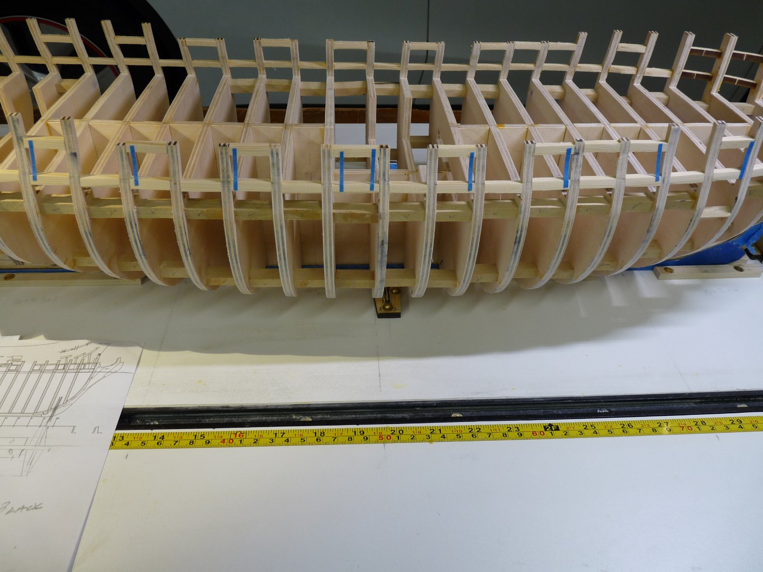
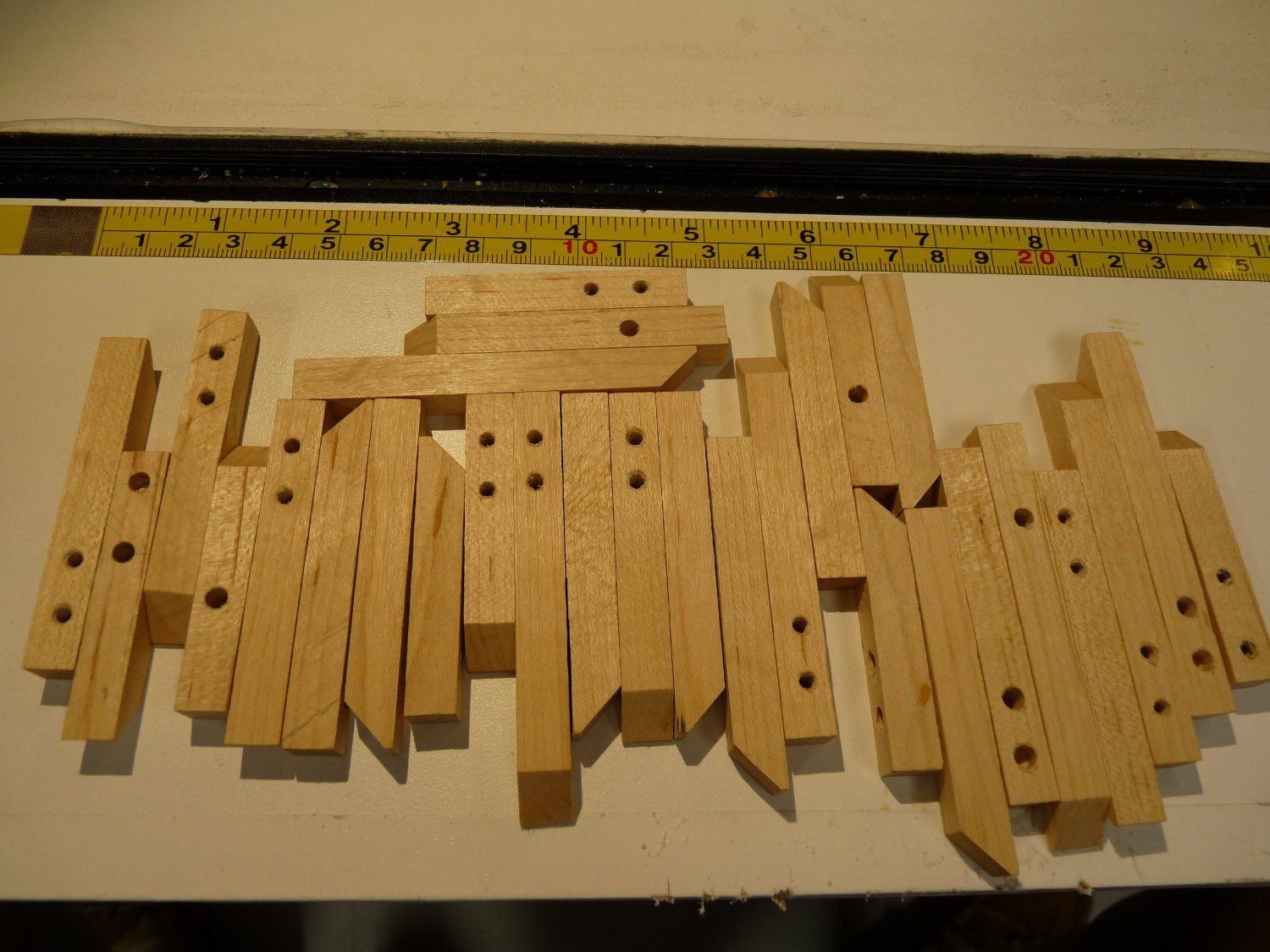
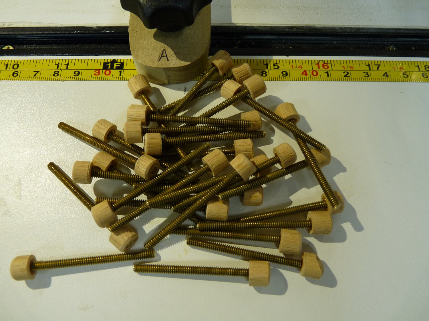
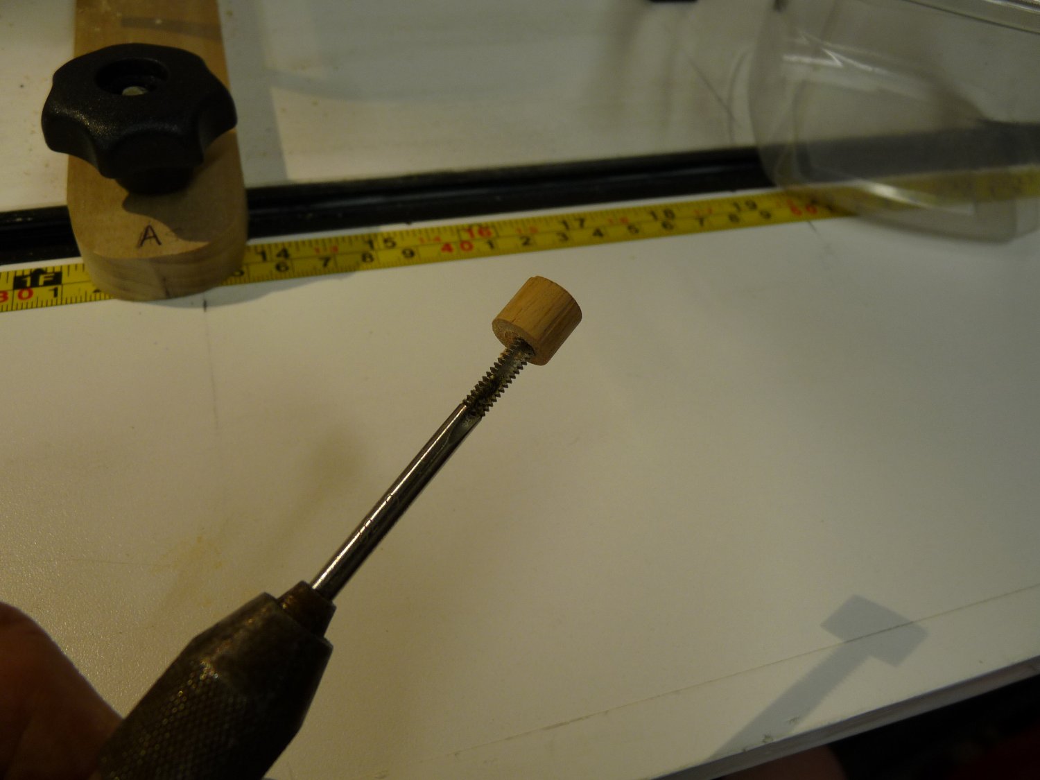
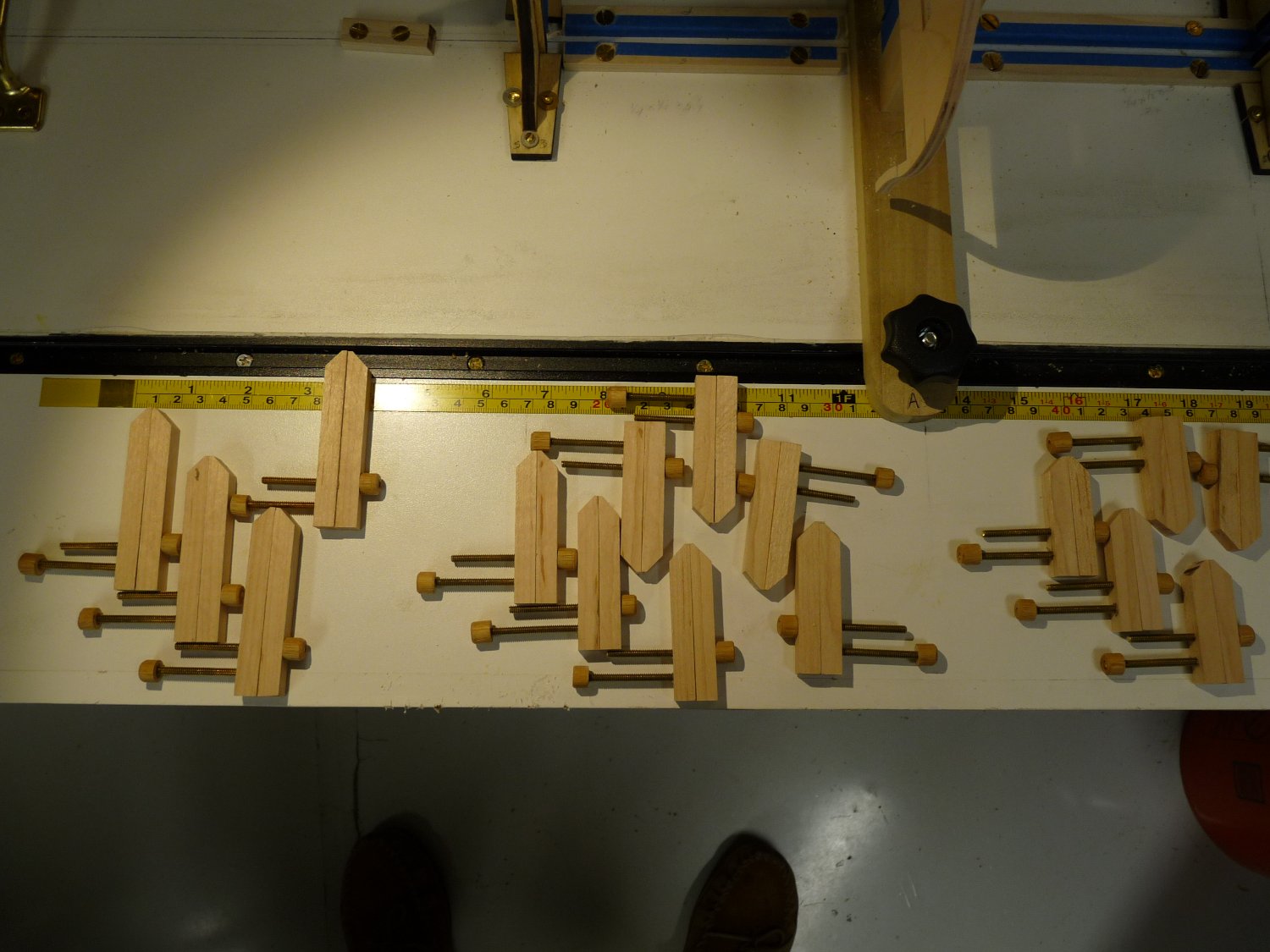
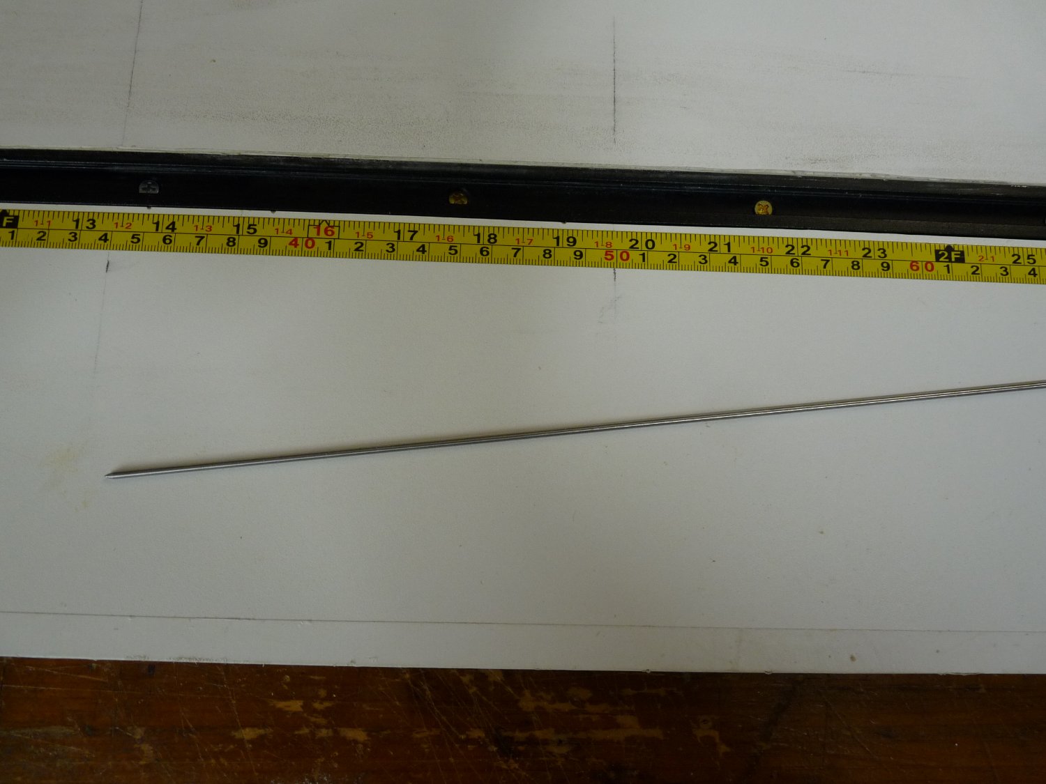
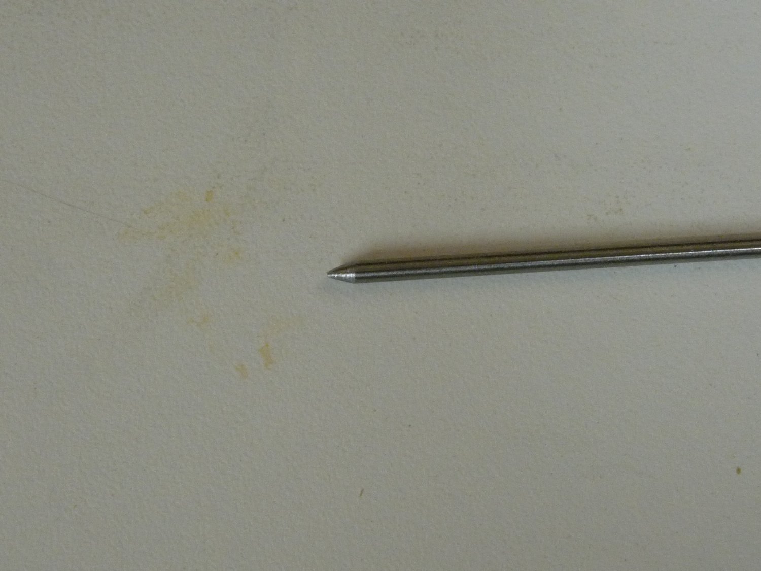
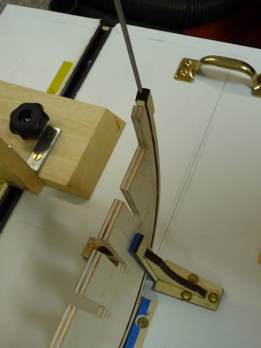
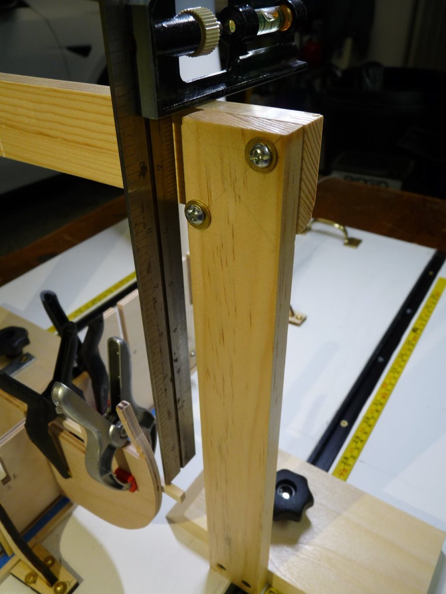
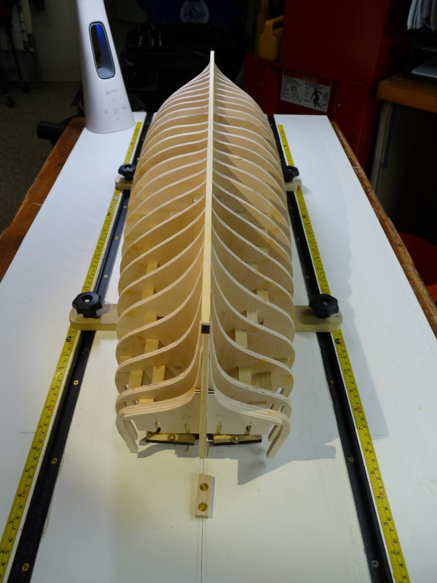
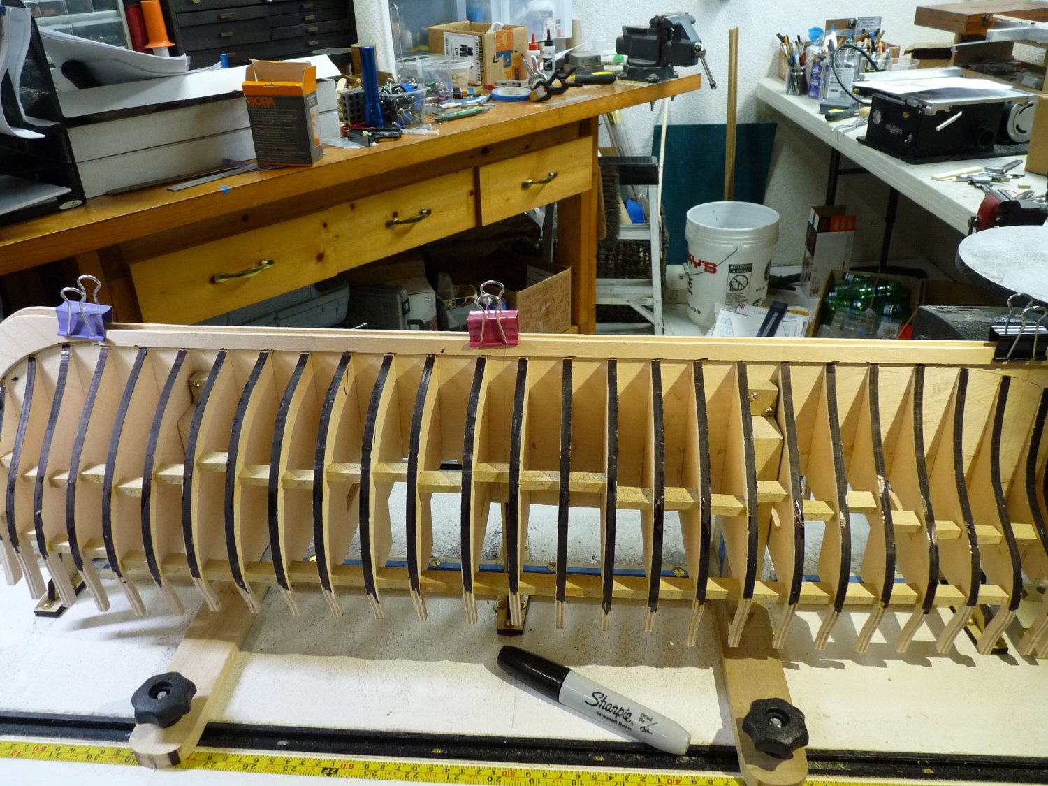
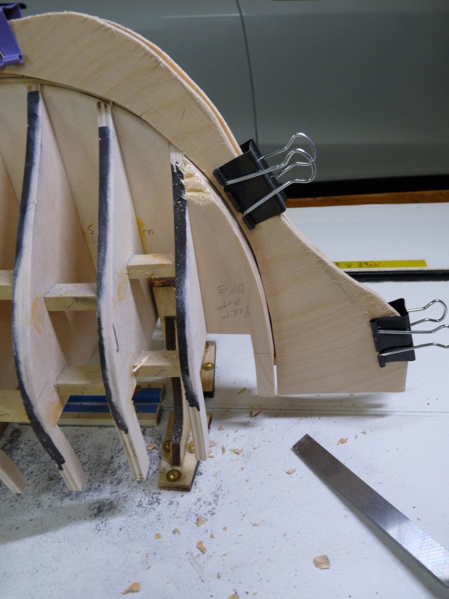
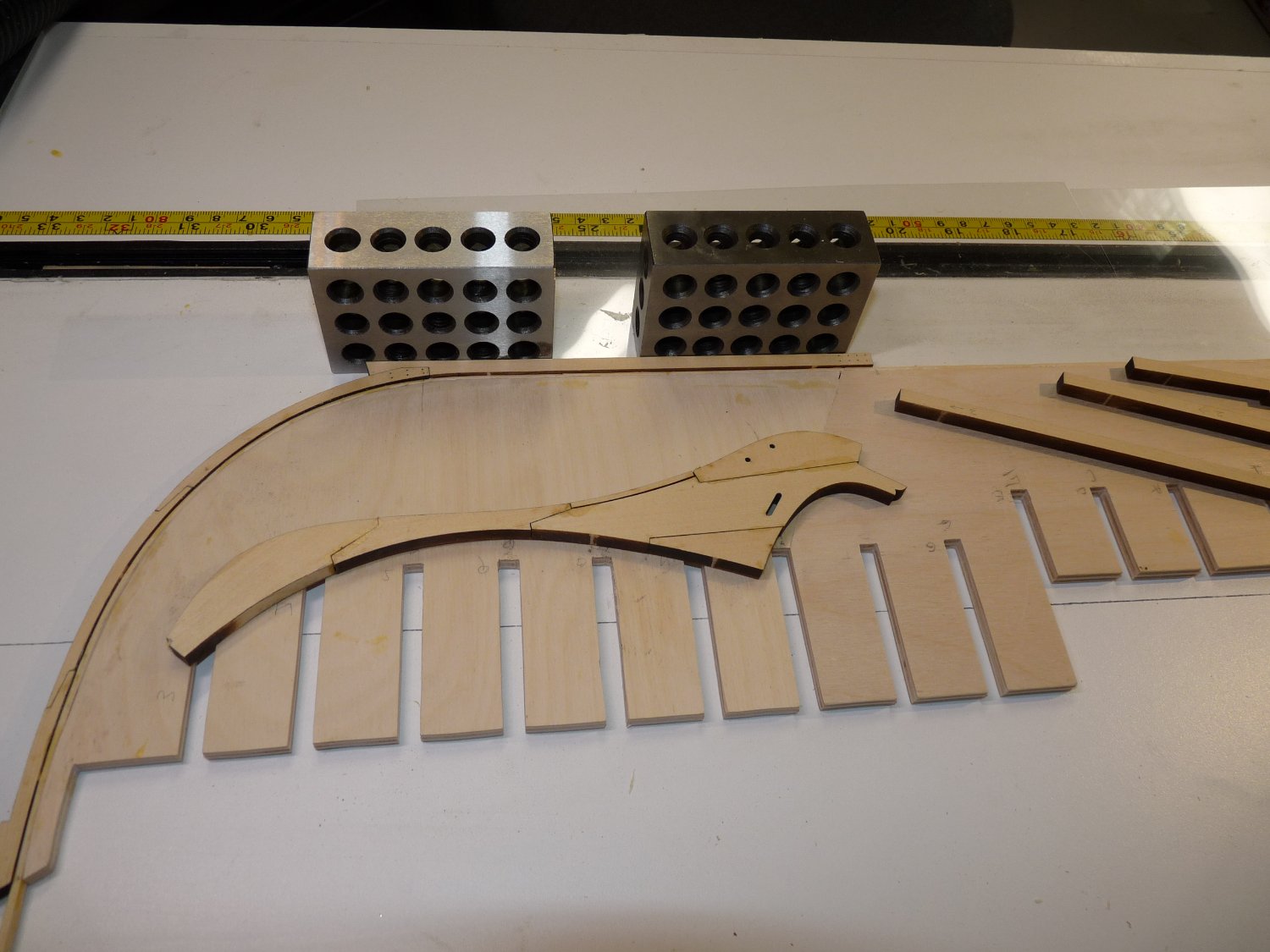
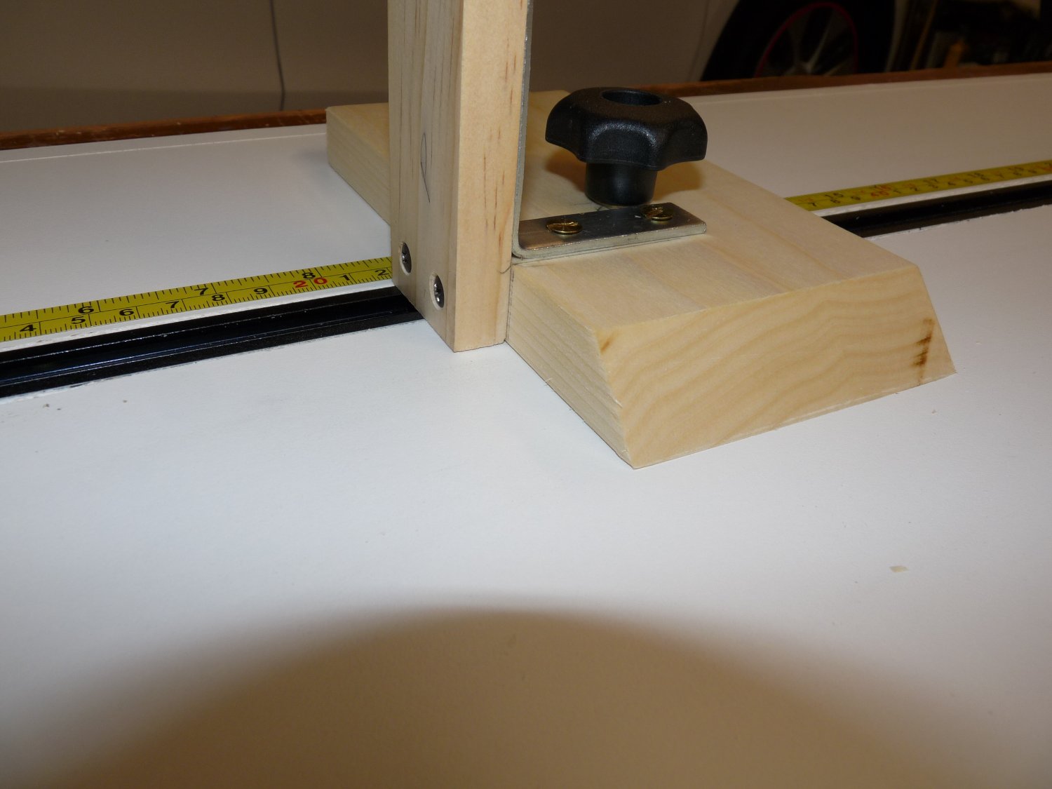
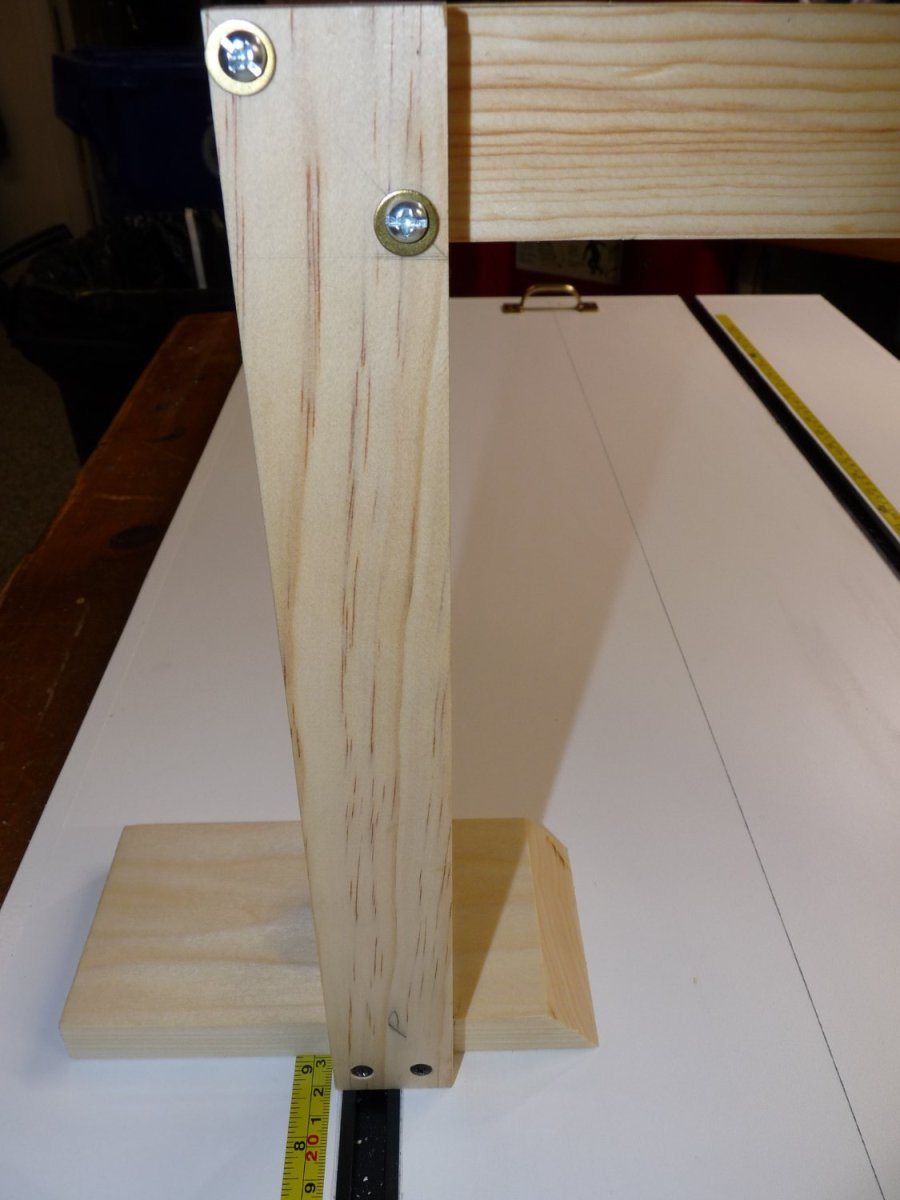
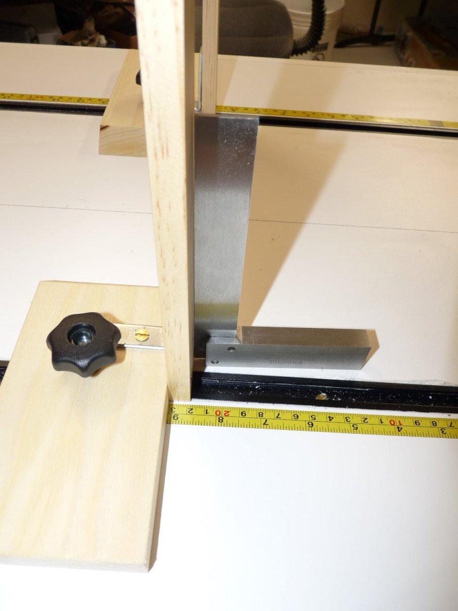
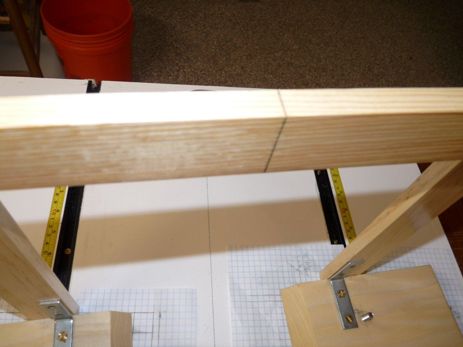
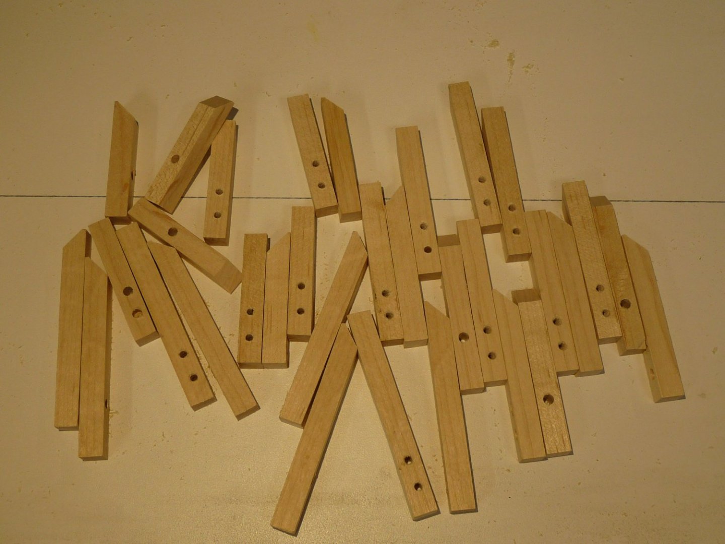
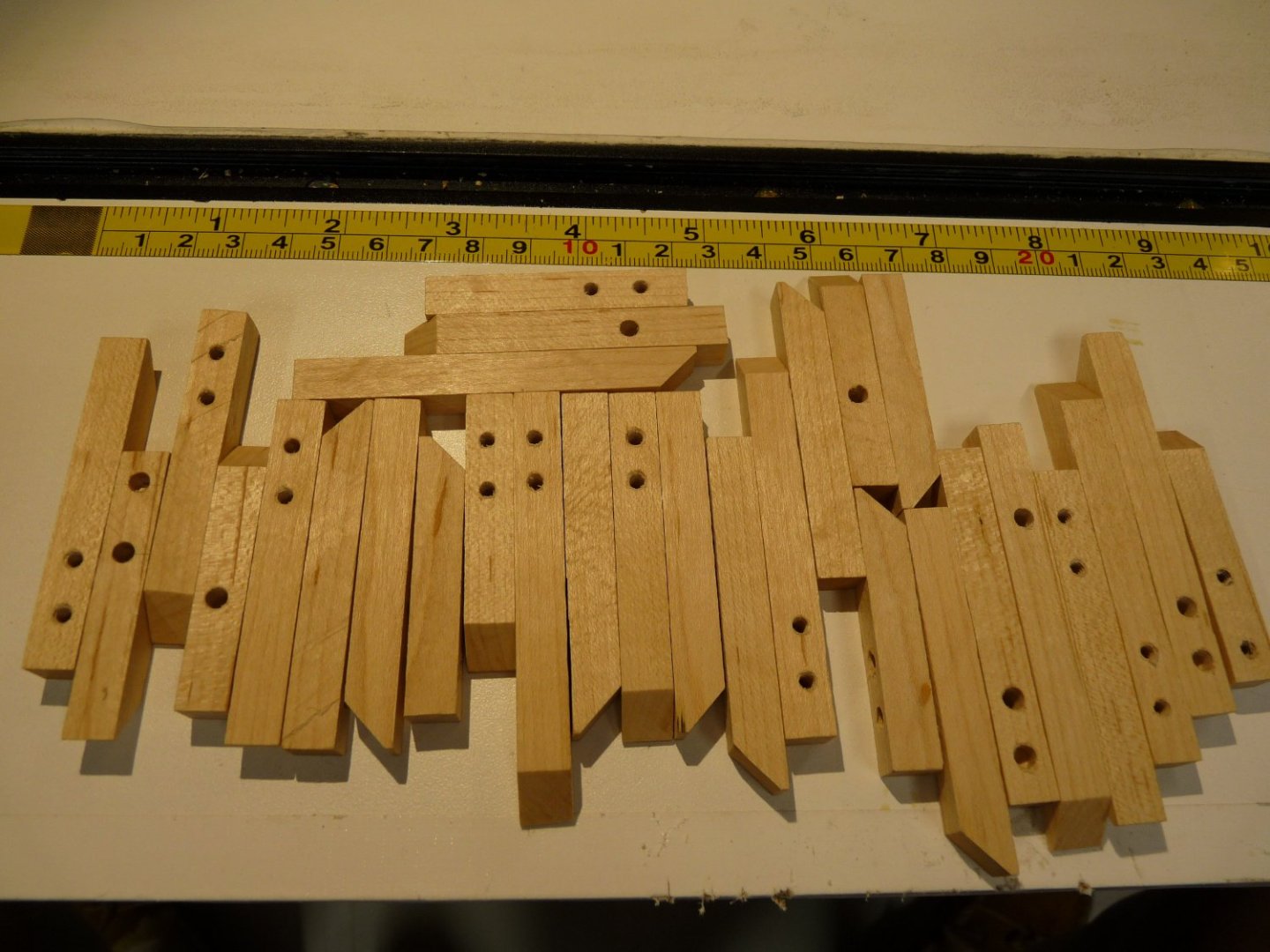
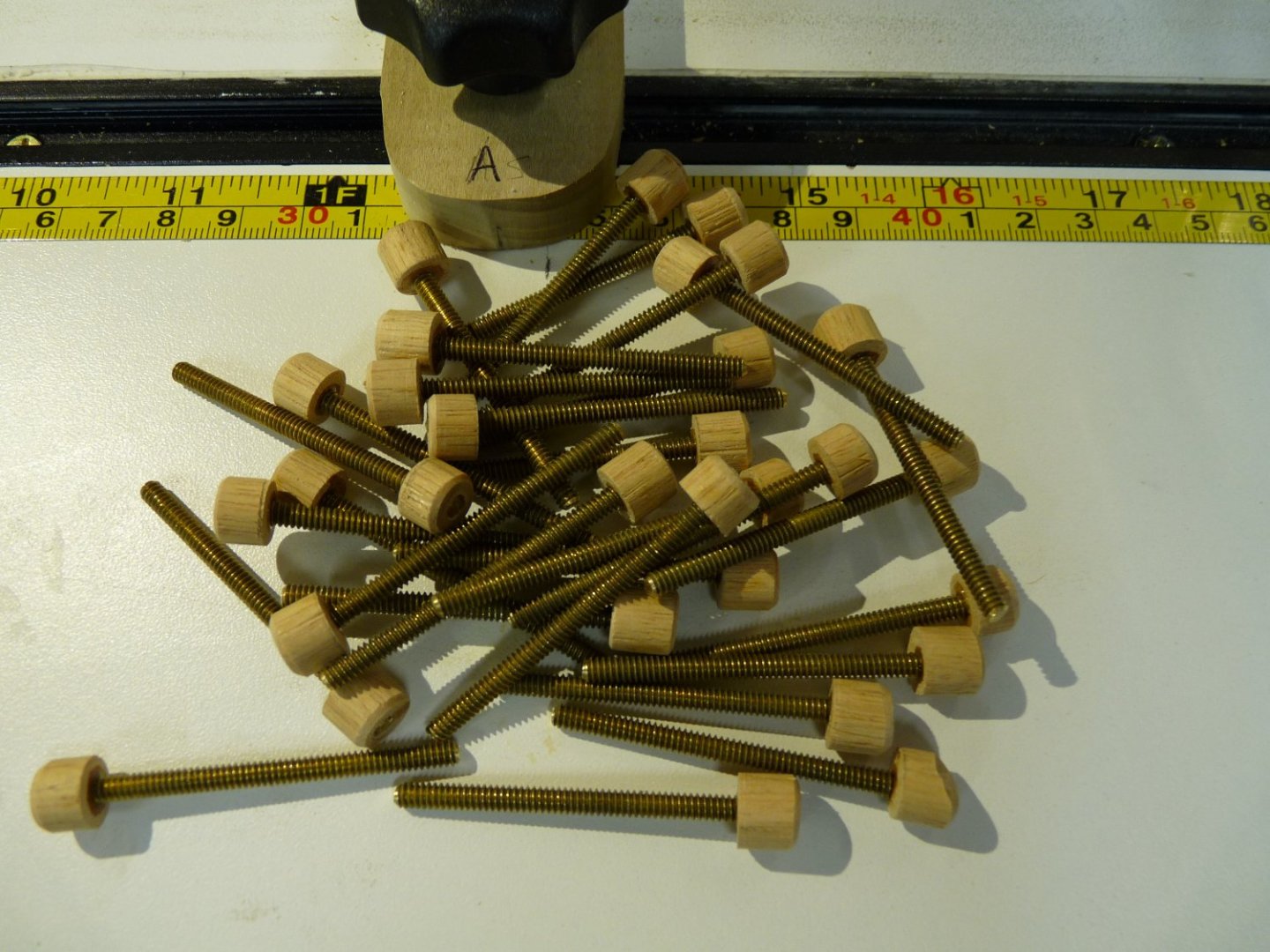
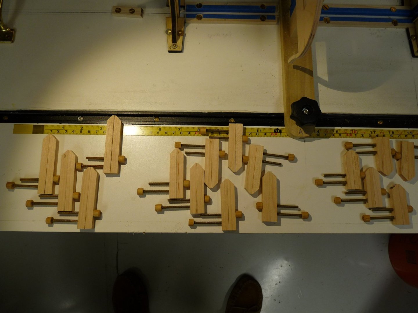
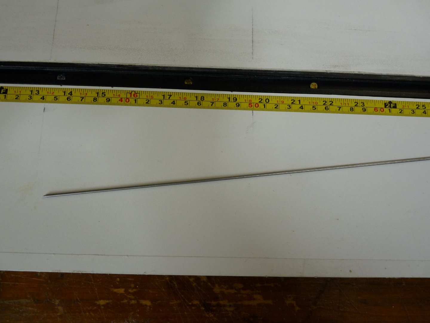
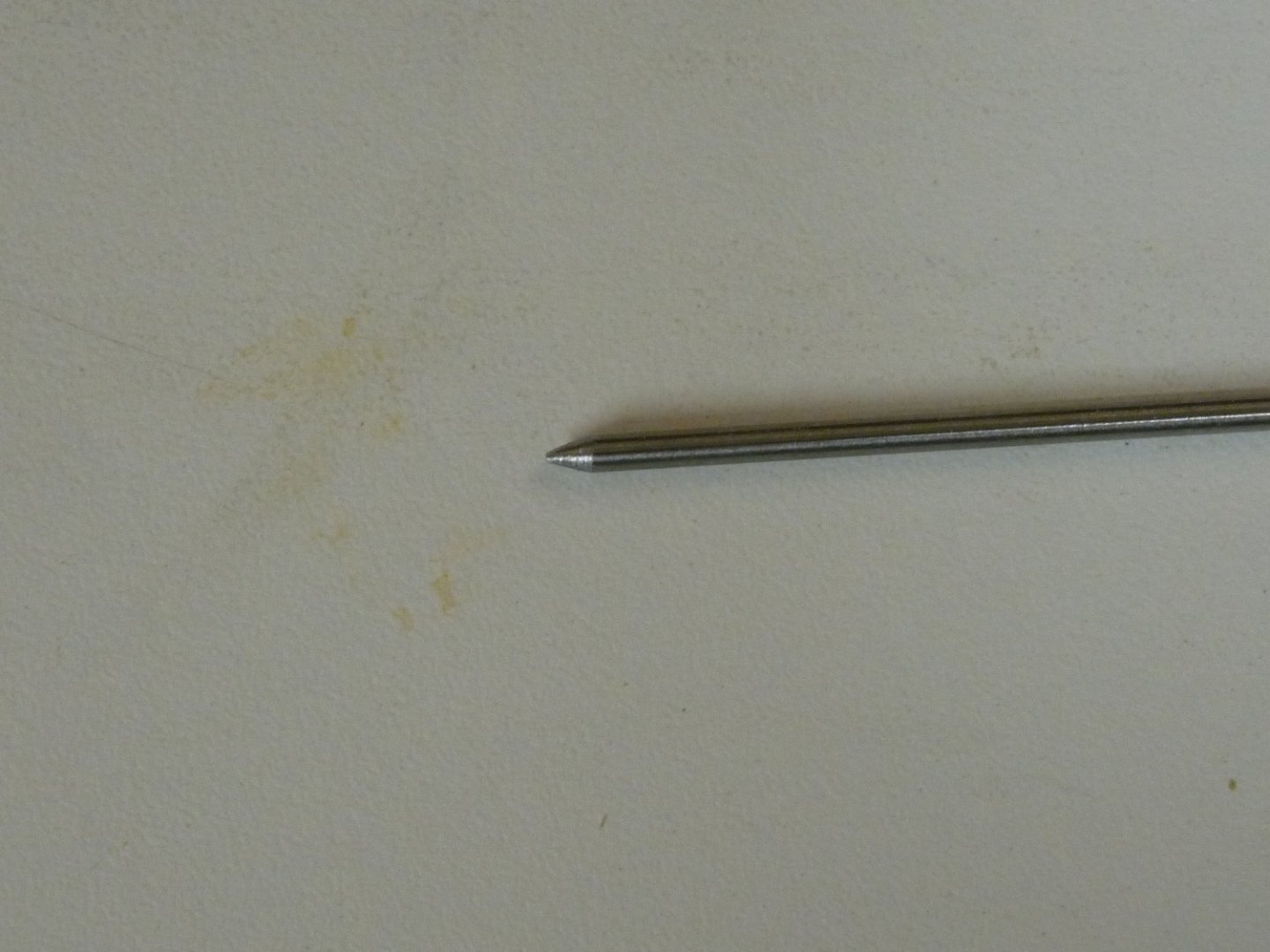
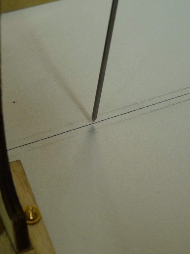
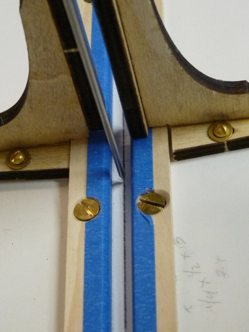
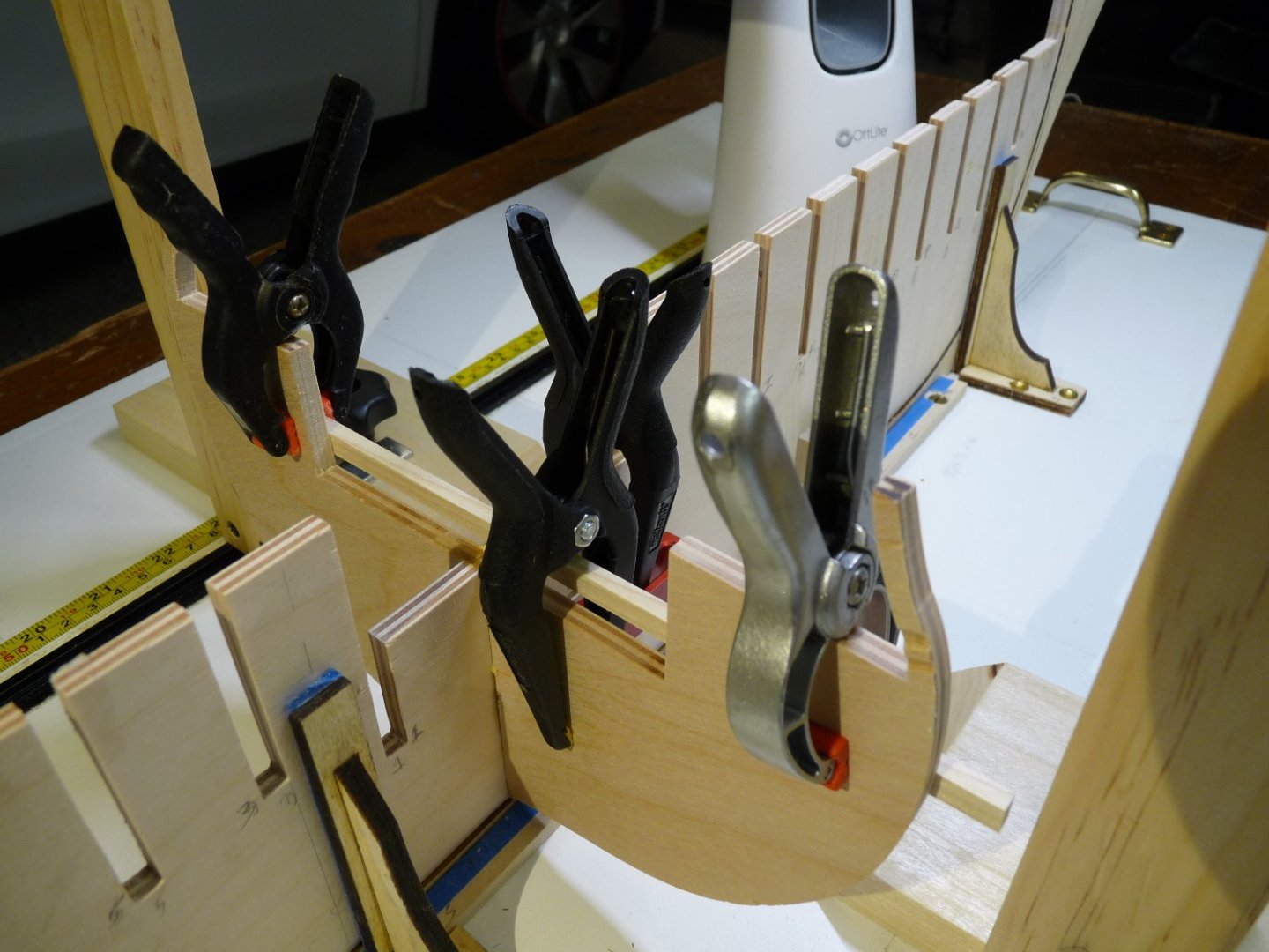
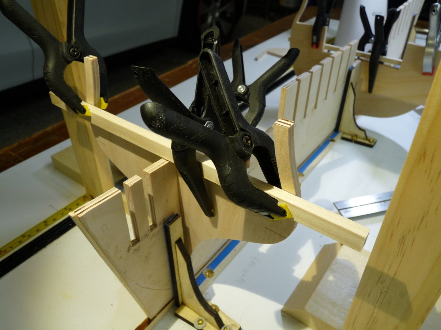
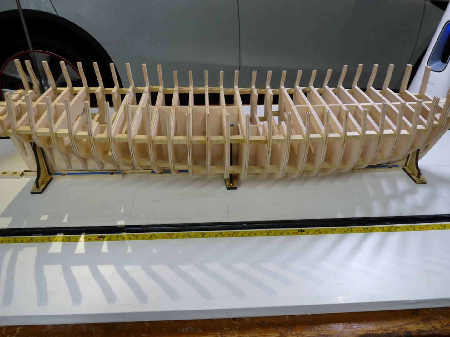
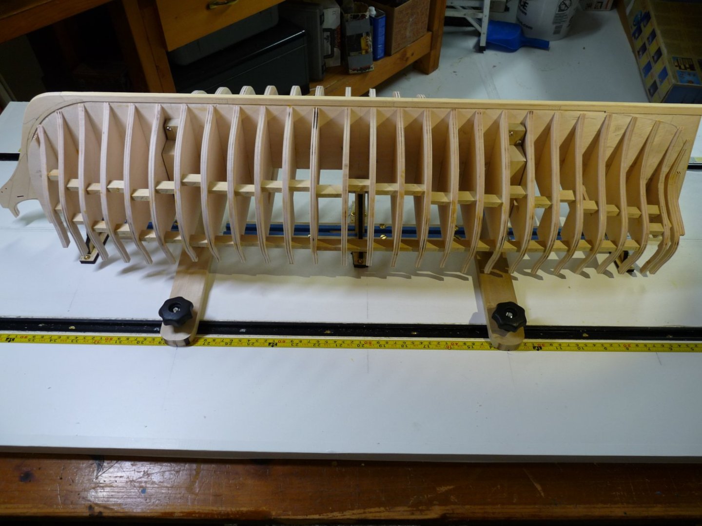
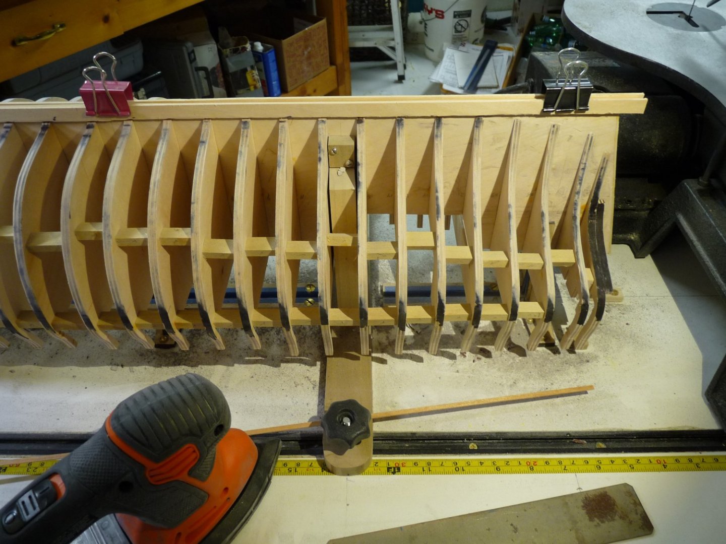
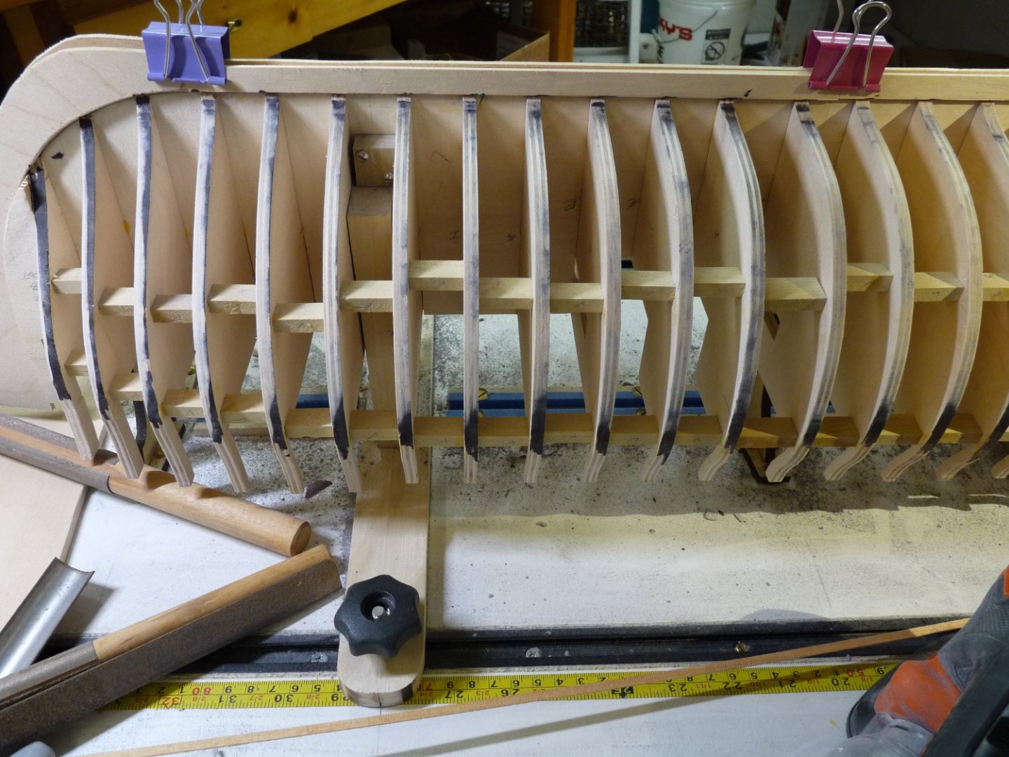
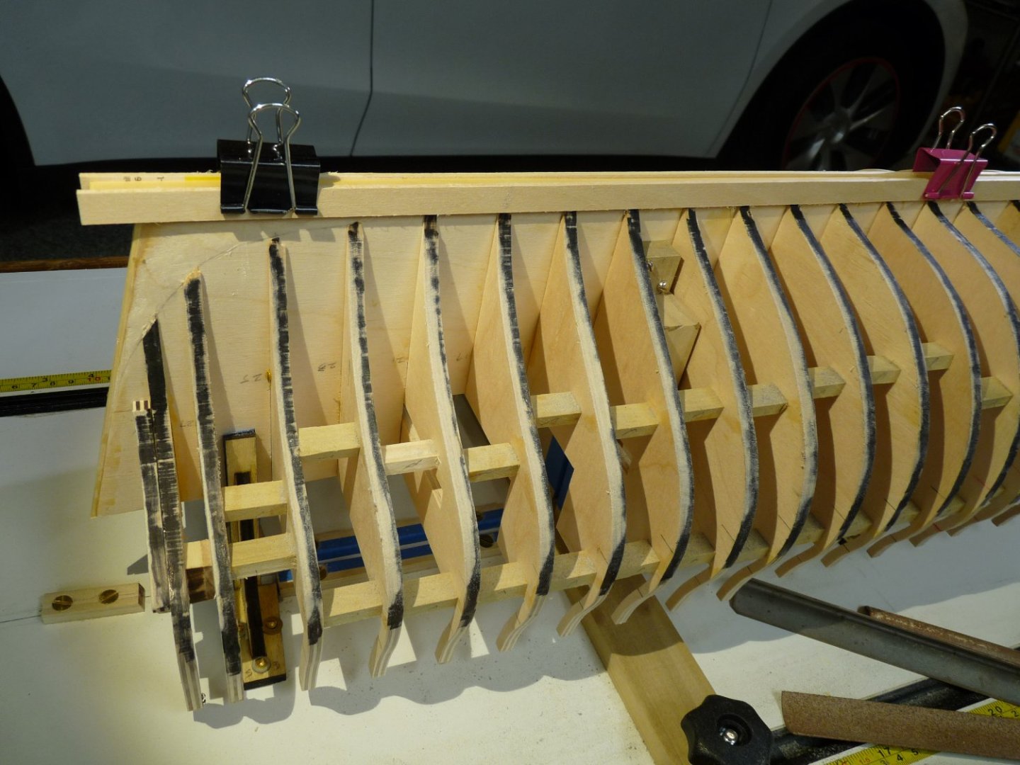
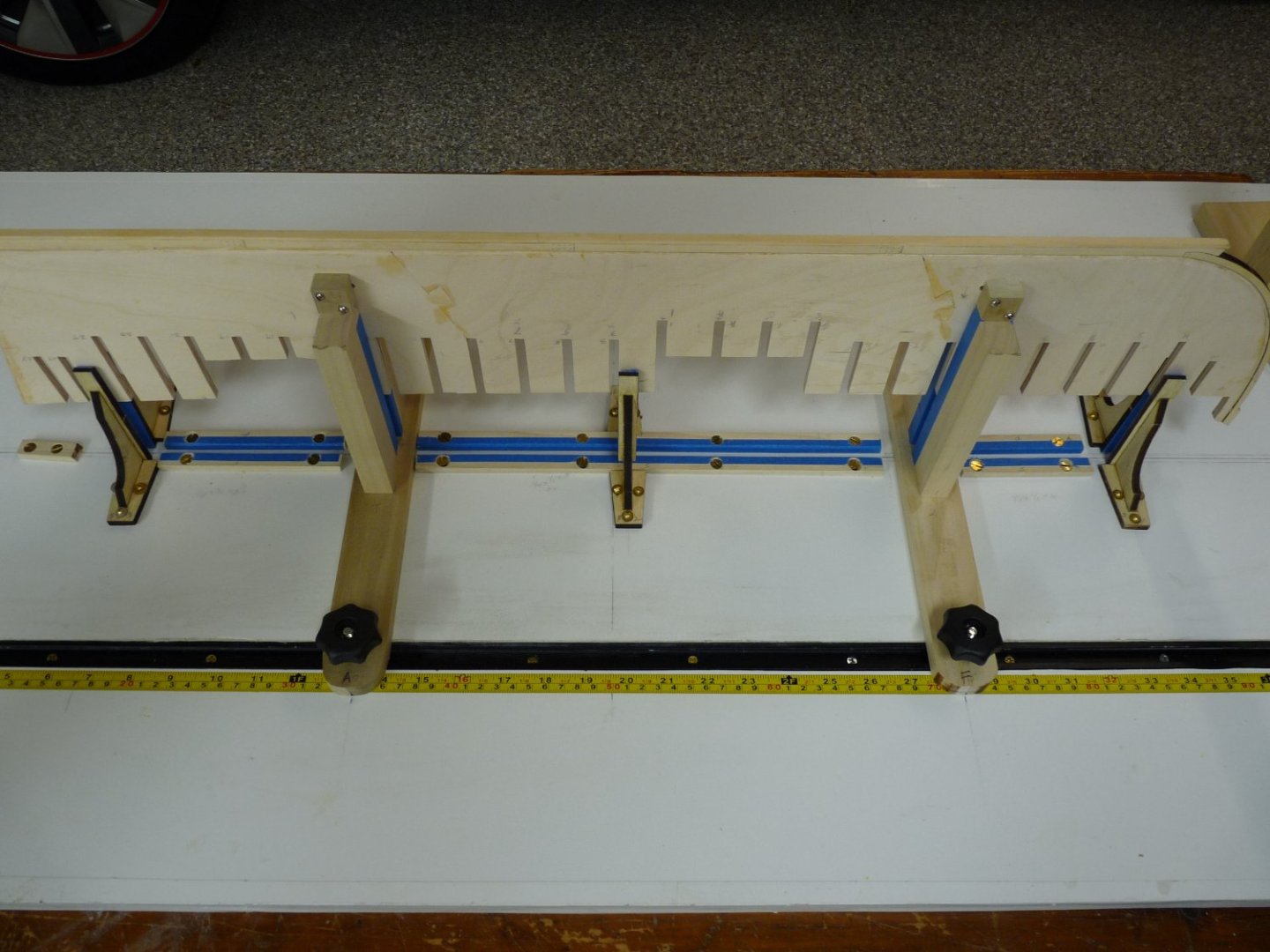
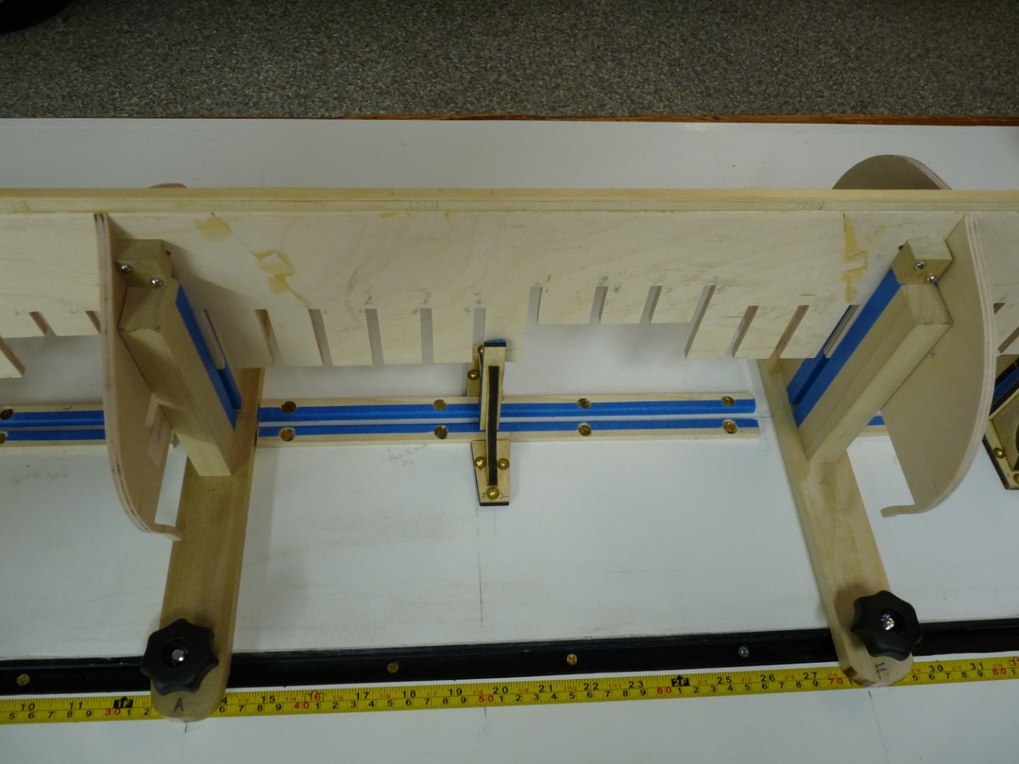
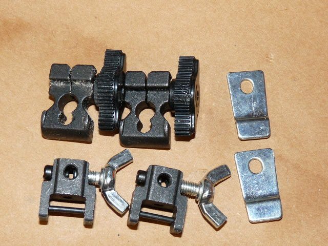
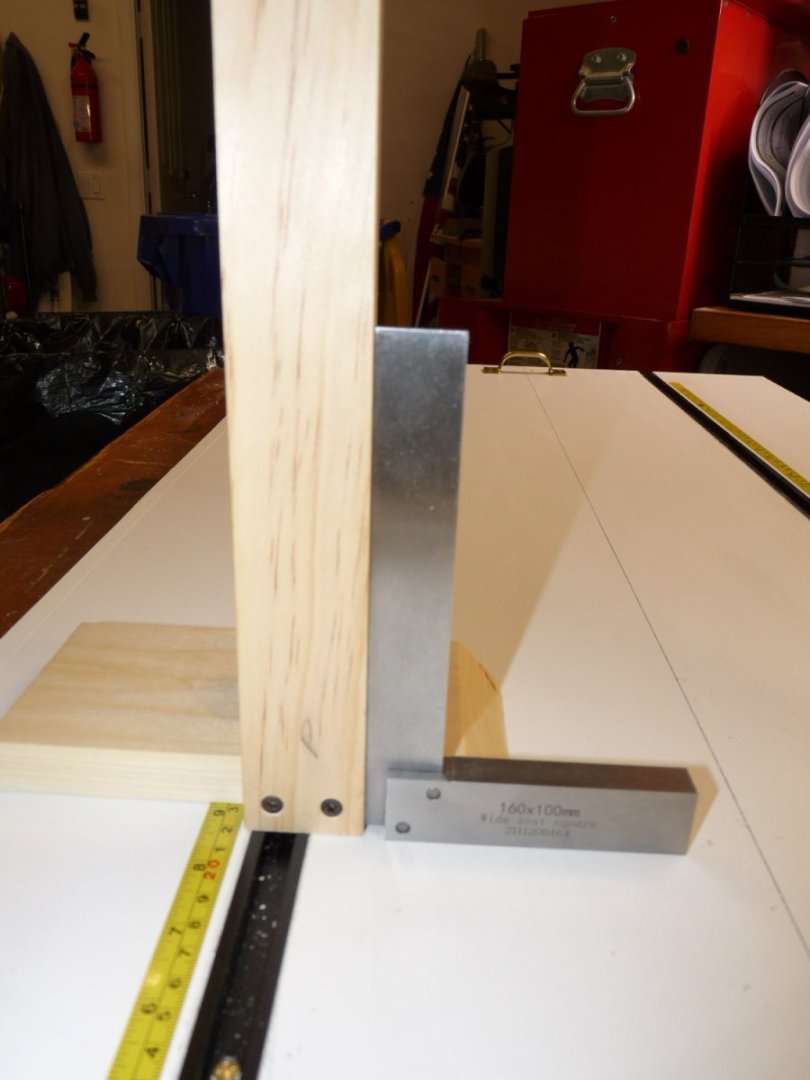
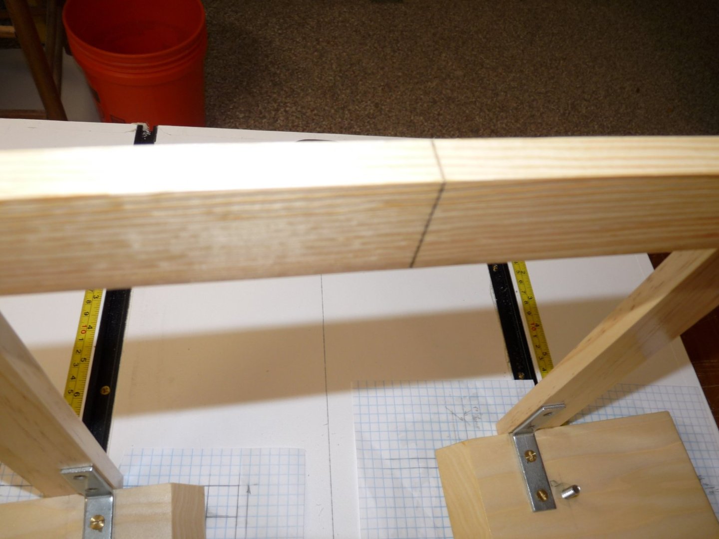
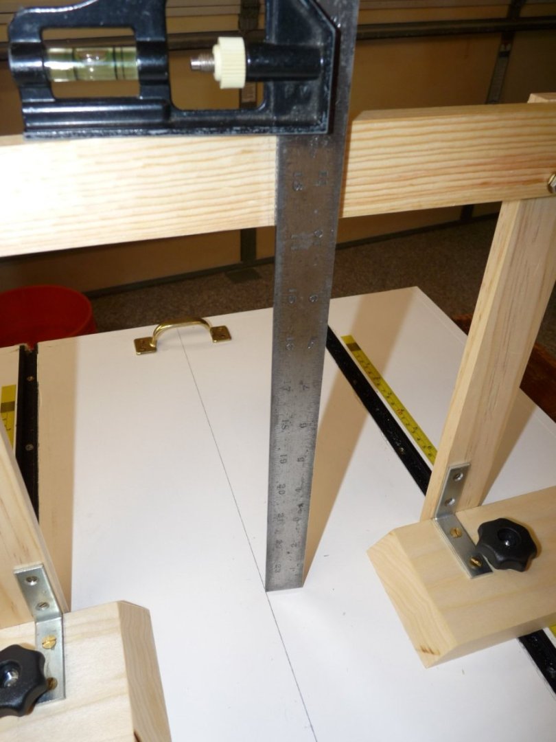
When I had some slack time, I decided to make up a few wooden clamps like the ones Ed Tosti made in his book on Naiad. I had an old piece of ¾” maple board lying about, so I ripped it into 5/16” strips and then cut them into pairs of different lengths – 2”, 2-1/2” and 3” long. 2-1/2” long pieces of 6-32 brass threaded rod was used for the screw mechanisms, and the threads that needed to be tapped in the arms were done right in the wood; no inserts needed. Small lengths of 3/8” dowels were drilled and tapped for the screw handles, epoxied in place. I don’t know that I’ll ever use them, but they will probably come in handy some day! Another adaptation I made to the build board gantry was to file a shallow v-groove with a triangular file exactly along the vertical centerline of the upper crossbar. I then took a 13 inch length of .087” dia. drill rod and sharpened one end. Now I can clamp the rod to the crossbar, located in the groove, and it will be registered along the build board’s centerline. It’s removable, repeatable and accurate to better than 1/32”; even better up higher on the model. I started adding the bulkheads, doing two at a time – one from the stern (#27) forward, and another at “A” also going forward. This way I could let the glue cure for a few hours before adding the adjacent bulkheads. Doing two at a time halved the time to complete the placement. To align them I utilized the locating ticks that Chuck had given for the gun port sills and/or the wales as location references. I knew my bulkheads were not as accurate as Chuck’s laser cut ones, but the best locators that I could use were the tick marks, which I had carefully transferred to the bulkheads from the patterns. My first attempts were to clamp a wood strip across the bulkhead, aligning it with the reference ticks. Then I used a machinist’s square to measure down from the gantry crossbar to either side of the bulkhead to ensure that the distances were equal. If the bulkhead is square to the former and not rotated around the model’s long axis, these measurements should be identical. If not, then the slot in the bulkhead is not parallel to the bulkhead’s vertical centerline, and the slot’s edges must be tweaked with a file until the distances with the square are equal. A small mini-square clamped to both the former and the bulkhead ensures that they are perpendicular to one another. I placed several bulkheads using this procedure, but was unhappy with the work entailed and the accuracy of the results. I then made a sliding height gauge (a’ la Tosti) that made the work tremendously easier, and the gauge will be of great use down the line, I’m sure. It’s just an upright piece attached to a flat base, with a sliding arm that goes up and down. I made the whole thing out of poplar wood in an afternoon. Ed’s version has a thumbscrew to lock the measuring arm in place, but mine came out with the sliding mechanism so tight that the screw isn’t necessary, even though I included it. A small piece of brass sheet is captured under the screw’s end to protect the wood from being chewed up. This device really sped up the bulkhead attachment process, and it is much more accurate. Once all the bulkheads were in place, it was time to start fairing. I didn’t like the flexibility of the bulkheads and was afraid that they would move too much while I was filing/sanding the hull, so I added a bunch of small poplar spacer blocks between the bulkheads, being careful to place them where there would be no interference with the fairing process or the location of the gun port sills and lintels. After the bulkhead spacers were added, the hull was flipped over and placed on the build board using the fixtures that I described in the last post. The setup worked beautifully, and the hull is rock solid for the fairing as I had hoped. Note that I have not yet added the stern frames; they are too long for this setup, and would hit the build board when the hull is inverted. I may have to extend the fixtures to add a few inches to accommodate them if I need to work on the hull upside down later on. Before I began the fairing process, I blackened the edges of each bulkhead with a magic marker. Those who use Chuck’s bulkheads don’t need to do this; you have the laser char which does the same thing. As the hull is faired the black markings will sand away in the areas that need to be made smaller, generally the after edges of the after bulkheads (1-27) and the forward edges of the forward bulkheads (A-U). As I began the fairing process I realized that I needed to better protect the keel and stem assemblies from sanders, files and chisels. I made up some scrap cover boards for the keel, and cut some 1/8” ply to cover the stem section – all held in place with binder clips. I have gotten about ¾ of the way thru the fairing process, but am having trouble visualizing the correct curvature at the bow and stern sections. I am currently trying to fit some basswood bow filler blocks to see if they will make a difference in my attempts. Thanks for stopping by to take a look. Ted


-
Thanks, Chuck. And again, thanks for developing this amazing version of Winnie; I'm really enjoying the build and learning from those who have tackled her before me!
-
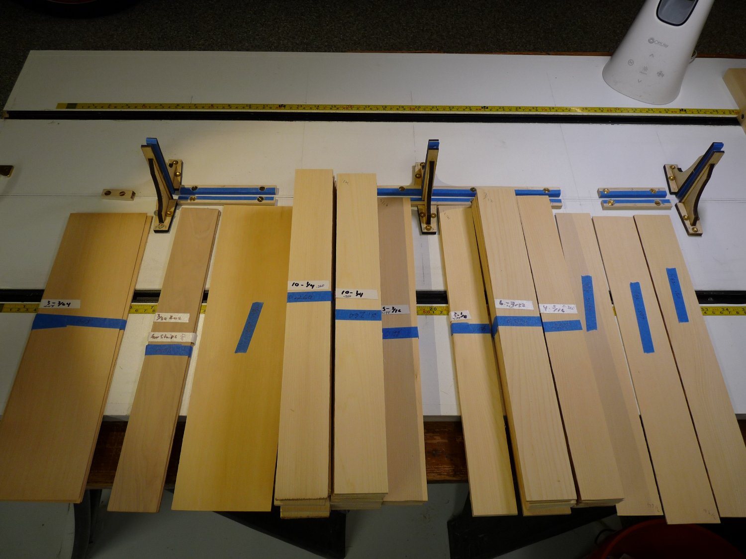
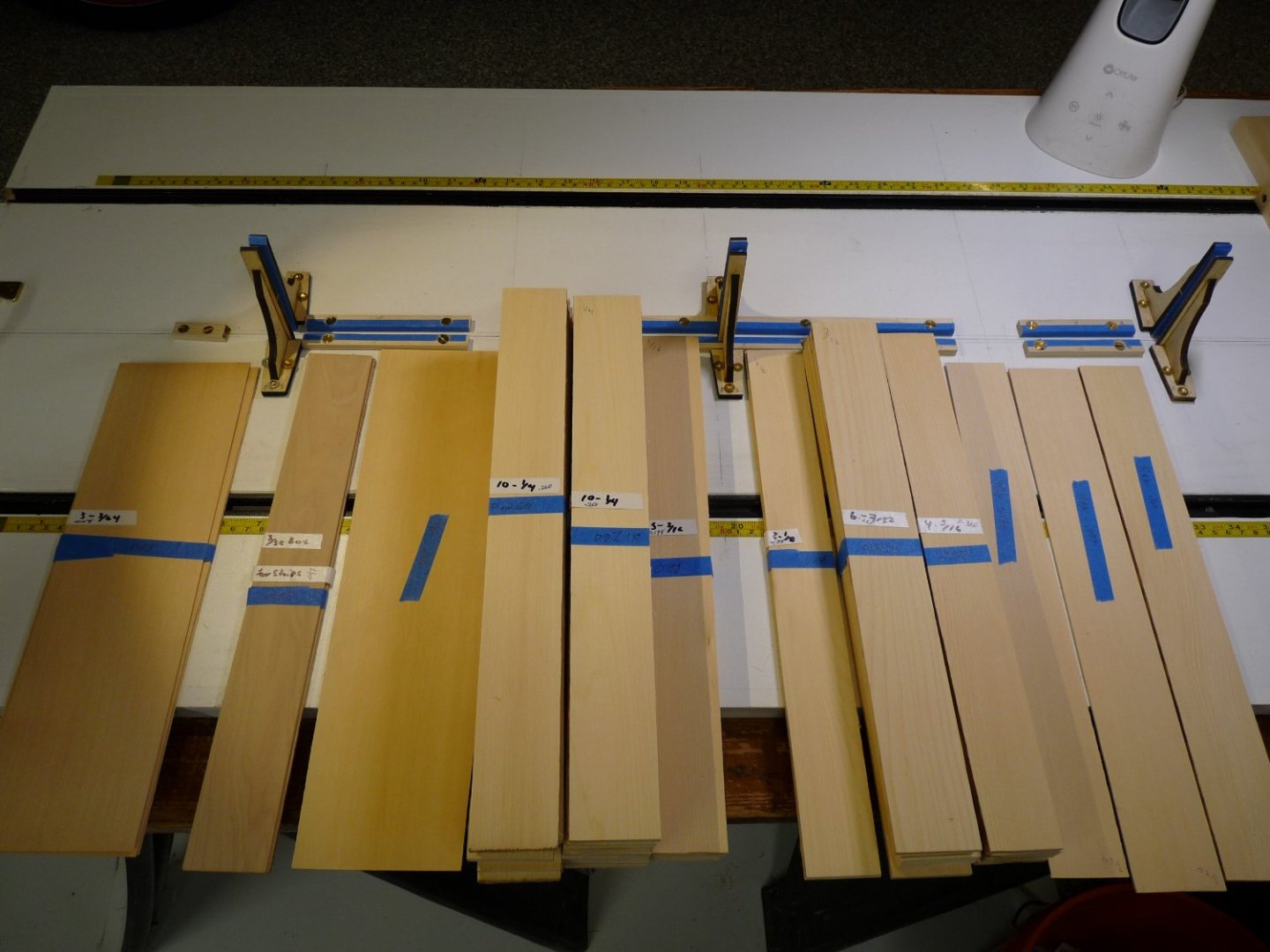
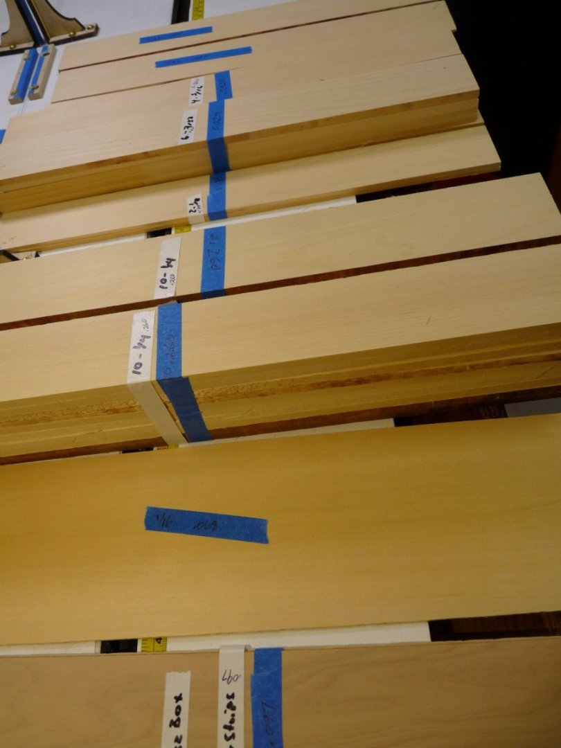
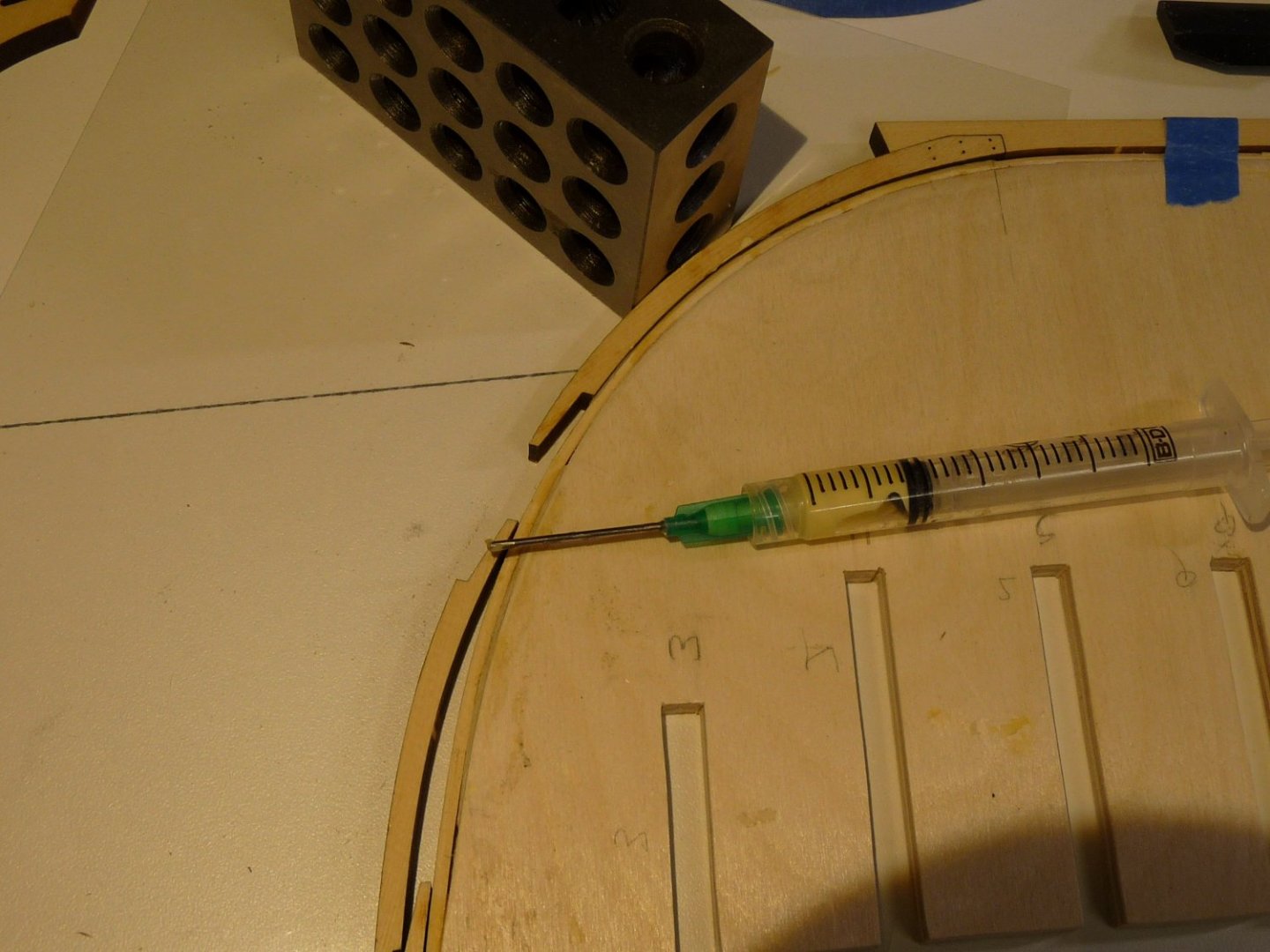
Some small progress has been made with the Winnie build over the last few weeks, while I have been accumulating tools and parts and have continued work on the build board and its attachments. As I will be milling all my own planking, decking, etc., I have ordered and received the Alaskan yellow cedar strips that are needed from Joe Volpe at “thewoodmansshed”. Beautiful stuff! I just told Joe that I wanted the blank wood for Winnie, and he figured out what I needed and sent along the wood; mostly in 2” wide slats about 14” long of many different thicknesses. Here are the blanks as received from Joe. I have been using the Byrnes saw a bit, and am confident that I will be able to turn out consistently dimensioned lumber using it. I was a little surprised that seemingly other Winnie builders have not requested this before, as Joe had to make up a list of the required sheets for me. I glued the three former pieces together on top of the build board, using a long straightedge to bank against and a couple of pieces of mylar under the joint areas to prevent them sticking to the board. I used a slightly different assembly sequence for the stem pieces than called for in the instructions. I wanted to use the prow curve that I had sawn on the former piece, which I presume is a little different from the laser-cut version that Chuck provides, as I can’t get the same precision using the scroll saw as he can with the laser cutter. I used the former curve to check the rough fit of the stem pieces, and once satisfied that the fit was very close I added the rabbet strip to the glued-up former assembly. The curvature of the rabbet strip at the bow was helped along with the trusty travel iron. Then the inner three pieces of the stem assembly and the keel sections were installed atop the rabbet strip. I’ll mention here that I am using small syringes filled with Titebond II to apply the glue. The sharp syringe tips have been replaced with 1” long blunt tips to avoid puncturing myself. I use 18 ga tips which have an ID that accepts a map pin to prevent the tip from clogging. The glue can be precisely applied in a small bead, and can even be spread out using the side of the tip. I have several of these strewn around the build area as they seem to never be at hand when you want one; they will last for weeks without clogging up with the pin in place. Before I added the keel pieces to the former assembly, I made up the simulated bolts at the box joints, staggered on opposite sides of the keel. It’s so much easier to do these now than after the keel pieces are attached to the formers. I used one of the AYC blanks that the laser cut keel pieces came from to make a template to locate the bolt holes in all three pieces. The bolts were made from some black 15 lb monofilament fishing line (.013” dia). The intersections of the guidelines were marked with a needle, then holes were drilled with a #79 bit about 1/3 of the keel thickness deep, the lines dipped in some Elmer’s glue, then inserted in the holes. After the glue had dried, the ends were trimmed and the area sanded. Once the inner stem pieces and the keel sections were attached, I began the process of shaping the rabbet groove using chisels and sanding blocks. Adding dummy pieces of keel along the after end of the keel and stern post area helped in this regard. I then glued up the rest of the stem pieces against the three that had been installed earlier, but did not yet glue the assembly in place. I wanted to sand the forward section down to take the figurehead as per the instructions, and would rather do this before gluing it in place. To be sure of the fit, I wanted to have the figurehead in hand, so I ordered it from Chuck, along with the parts to be used in chapters #2 and #3. I had to order them sometime; might as well do it now, even though chapters 2 & 3 are likely months down the road. After receiving the cast parts, I sanded down the stem assembly and glued it in place, after ensuring that the figurehead area was sized appropriately. The false keel strips were added at this point. Further work was also done to the build board. Thinking about tasks further down the road, I was concerned about having the hull stable and solid while fairing and planking while it was inverted. I have seen others use pool noodles, rolls of paper towels, but wanted something more solid since I have used the Baltic birch ply instead of the softer hobby ply for the bulkheads, and I anticipate having to lean on the hull pretty heavily during the fairing process. I envisioned posts on either side of the former, both fore and aft, that would take the punishment. Making them moveable in order to bank against a couple of bulkheads to locate the hull fore and aft meant making gaps in the strips that hold the keel straight. The posts were placed at the quarter points along the hull, and small blocks that bank against the tops of the posts were added to the former to control it vertically to protect the stem and transom from any damage. After finding the correct placement for the posts, the keel locating strips were cut to size and added, as well as the brackets that I got from Chuck. Almost ready to start adding the bulkheads!


-
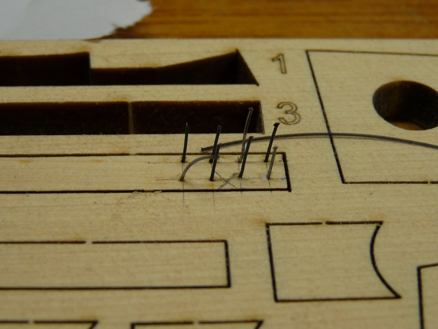
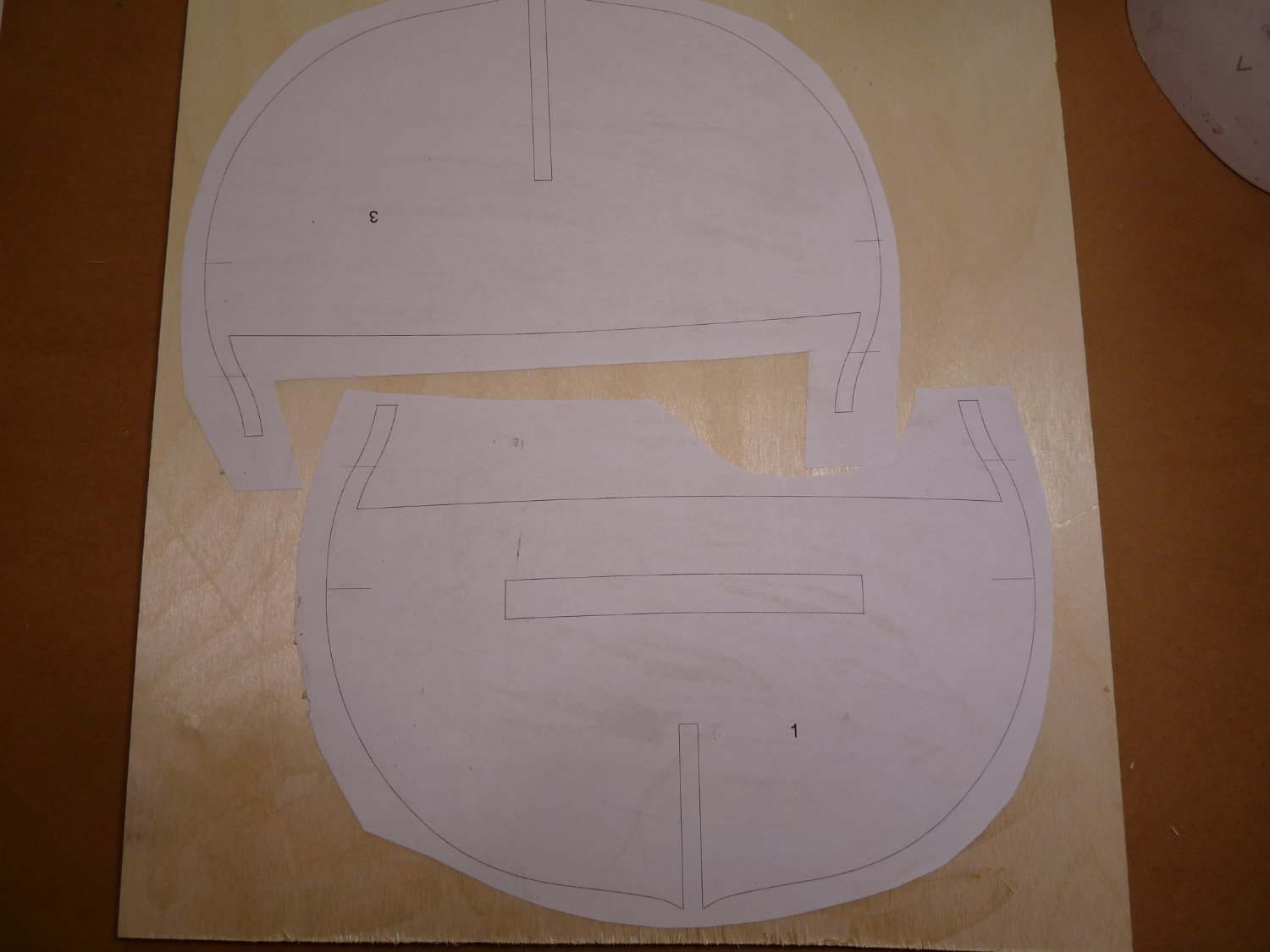
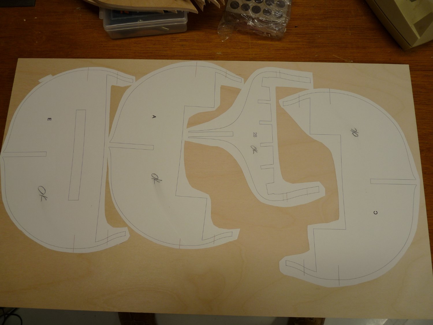
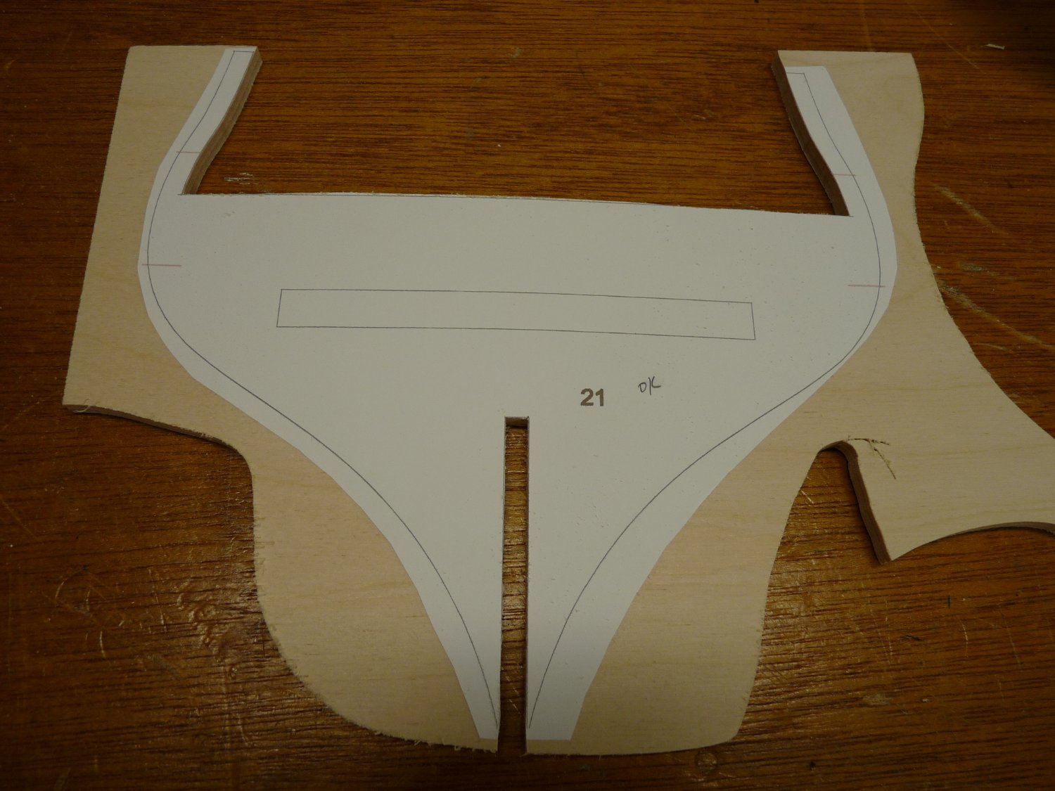
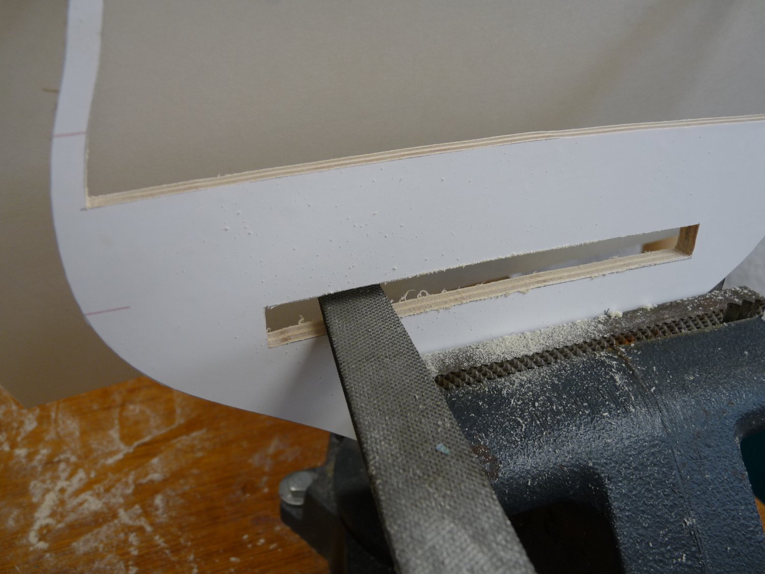
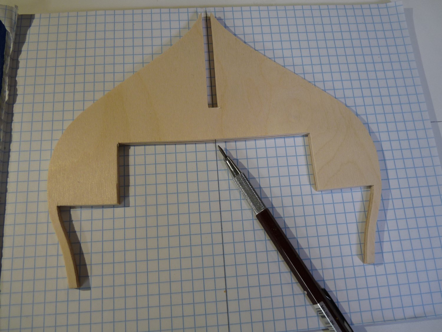
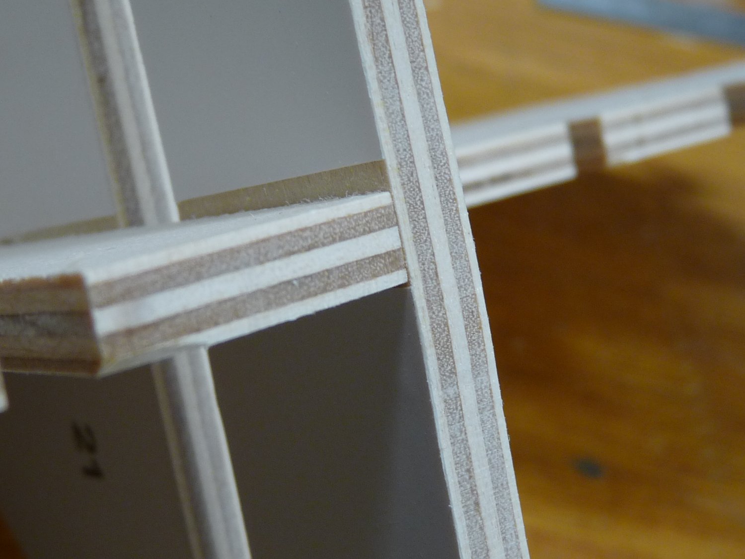
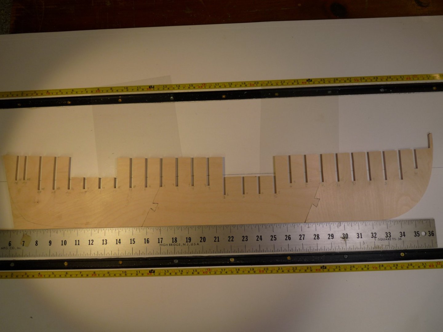
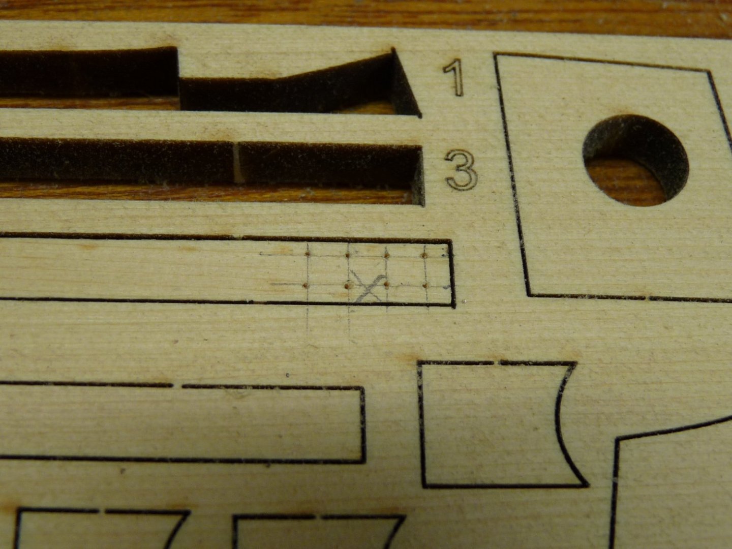
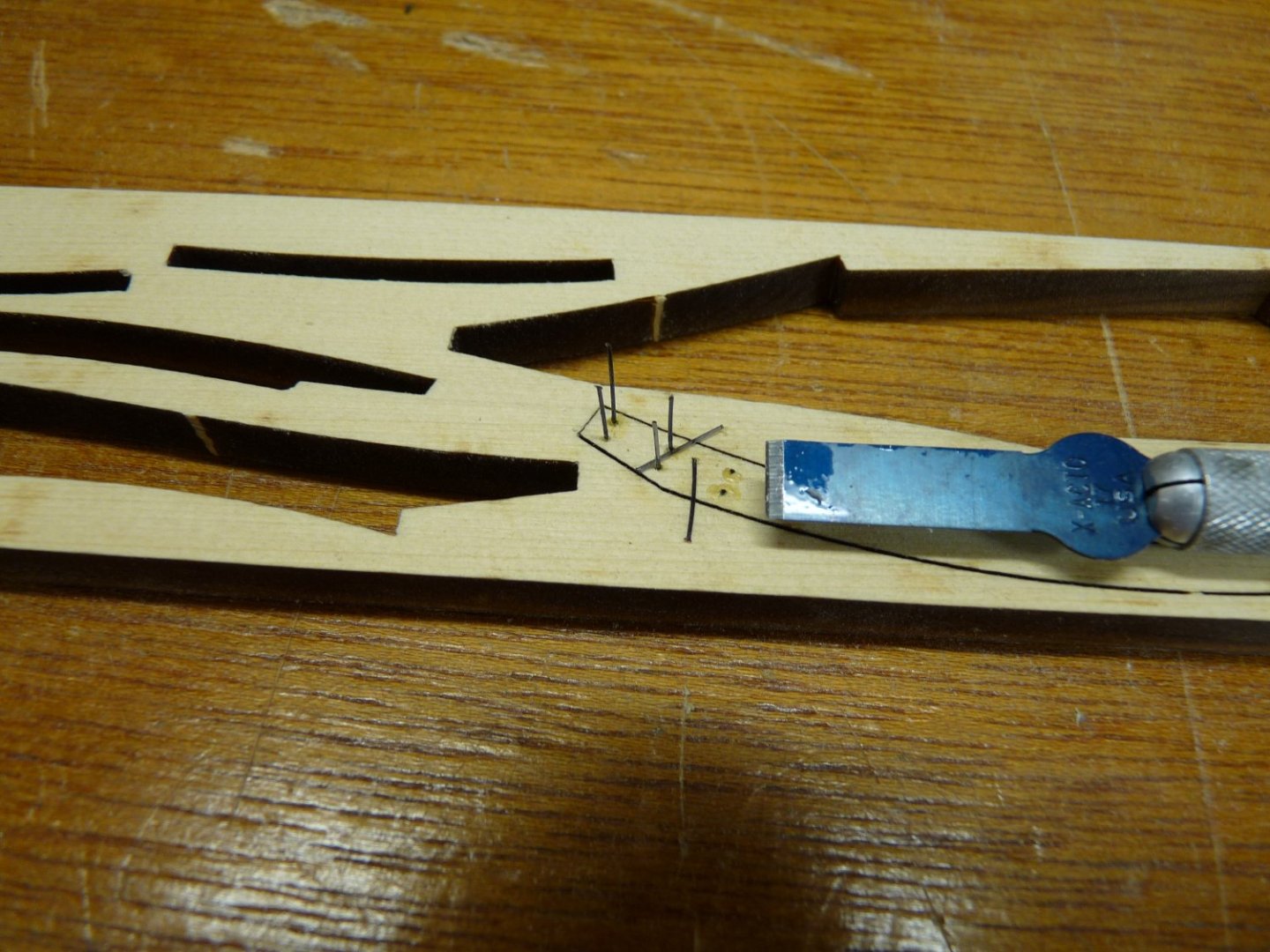
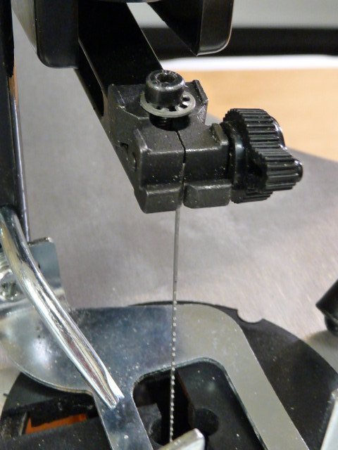
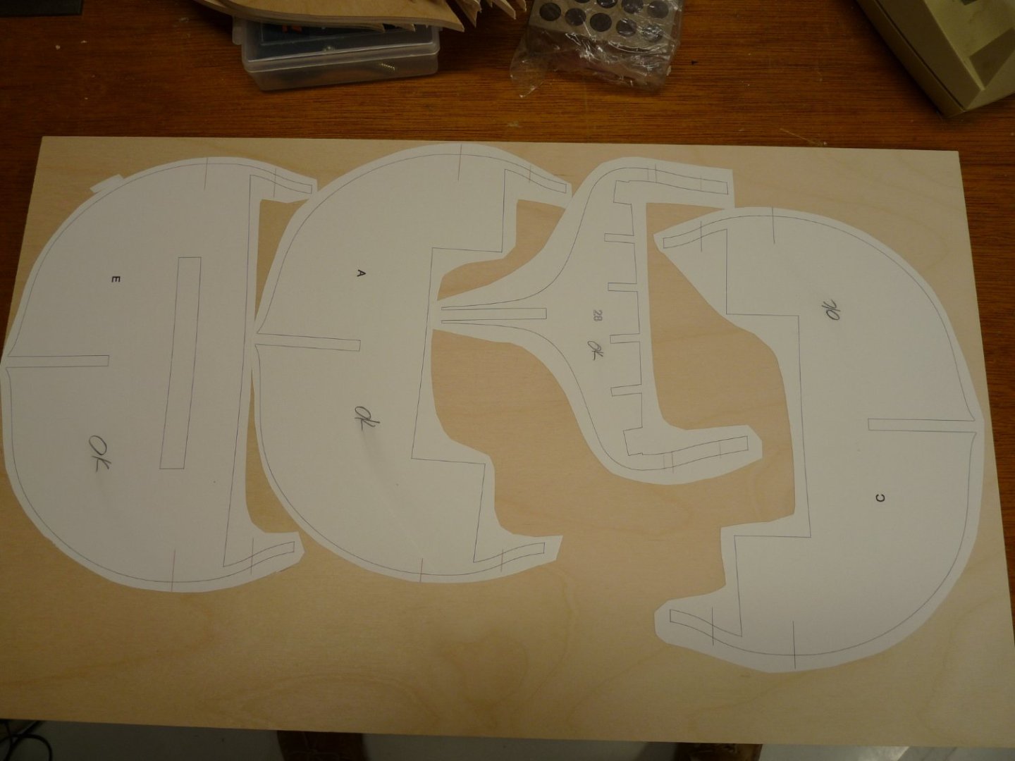
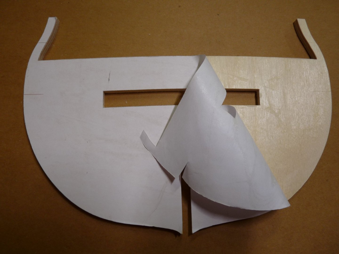
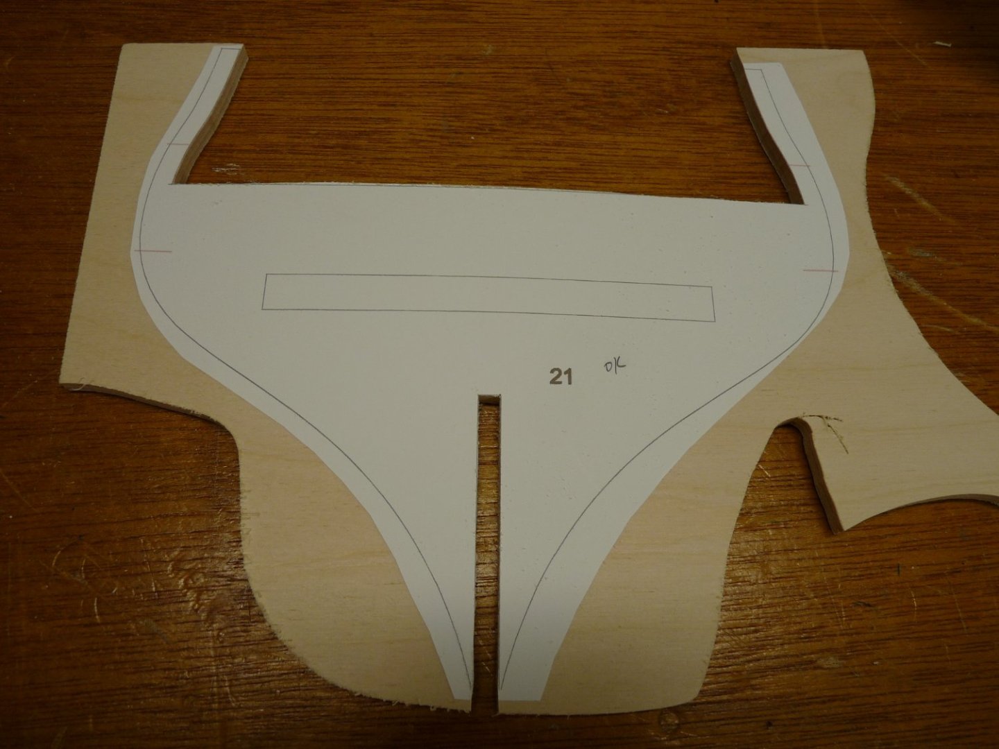
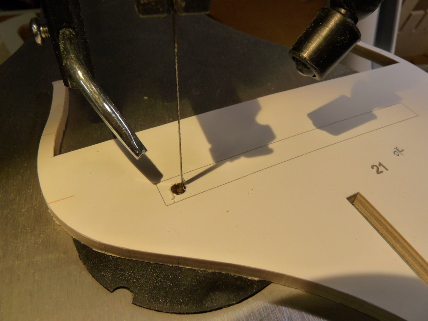
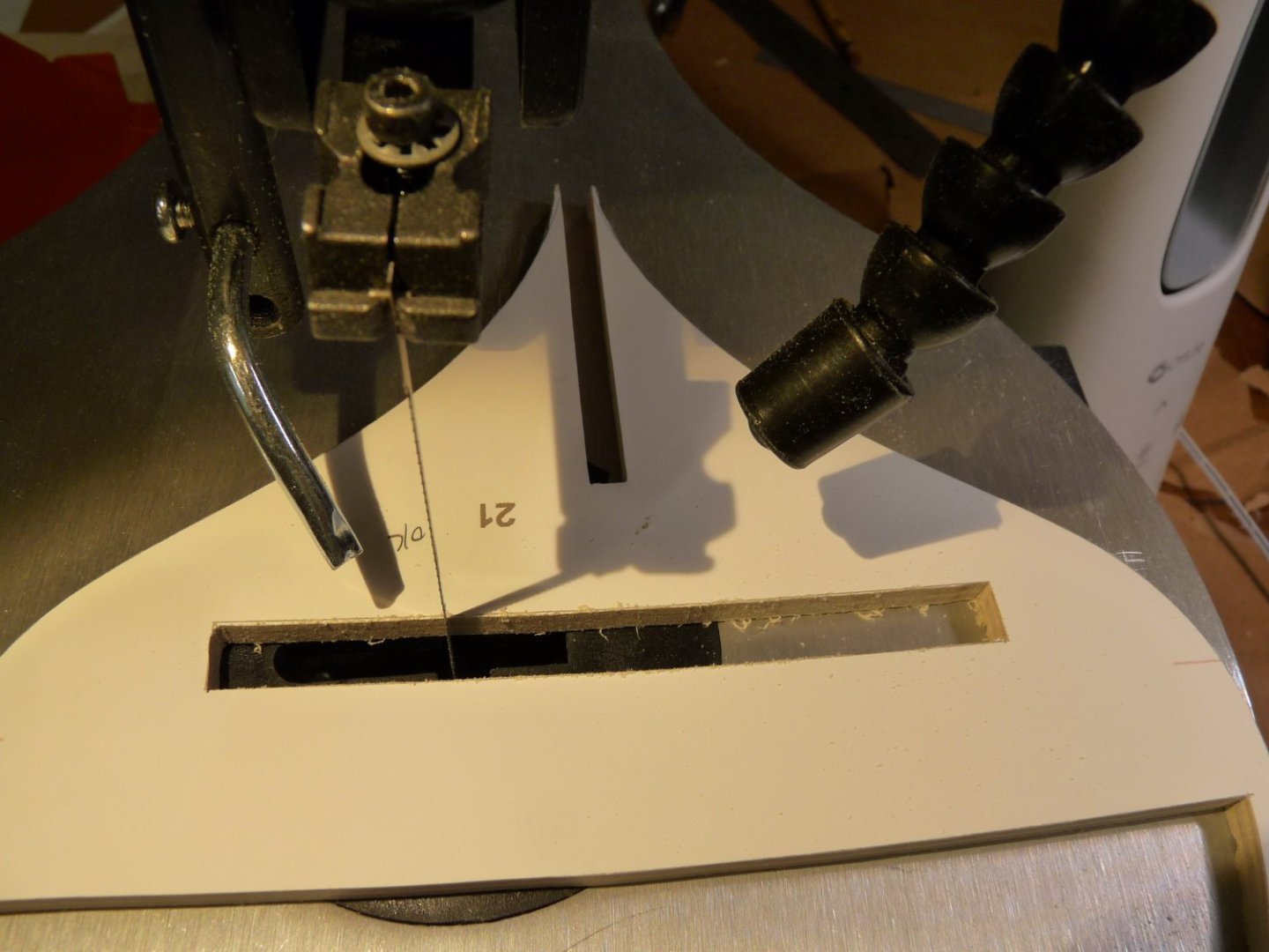
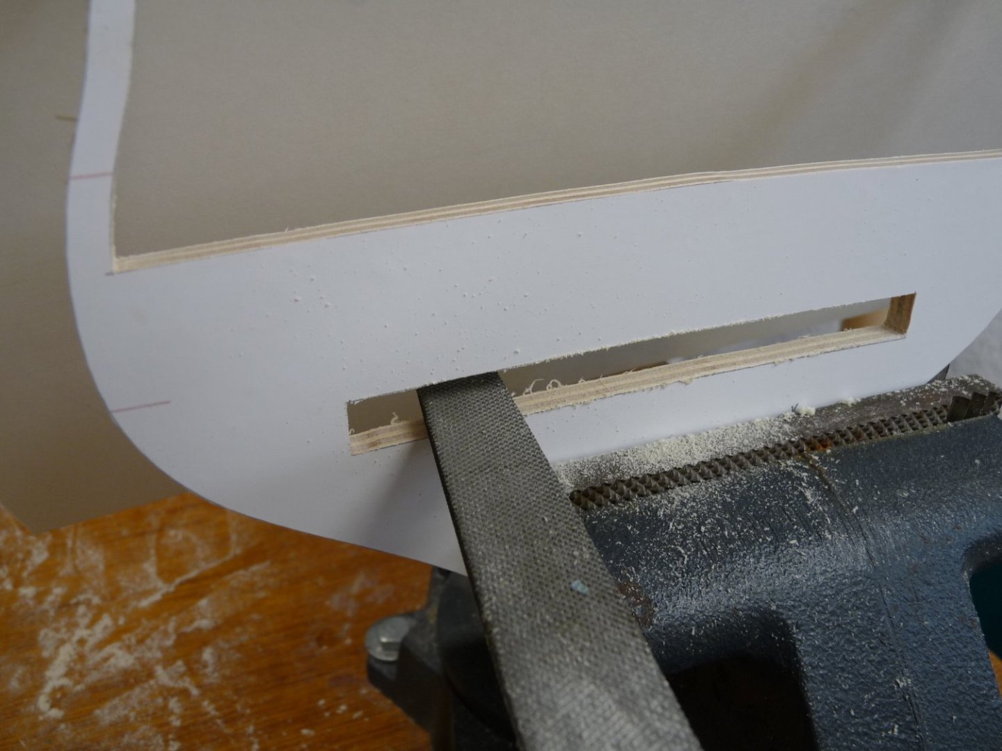
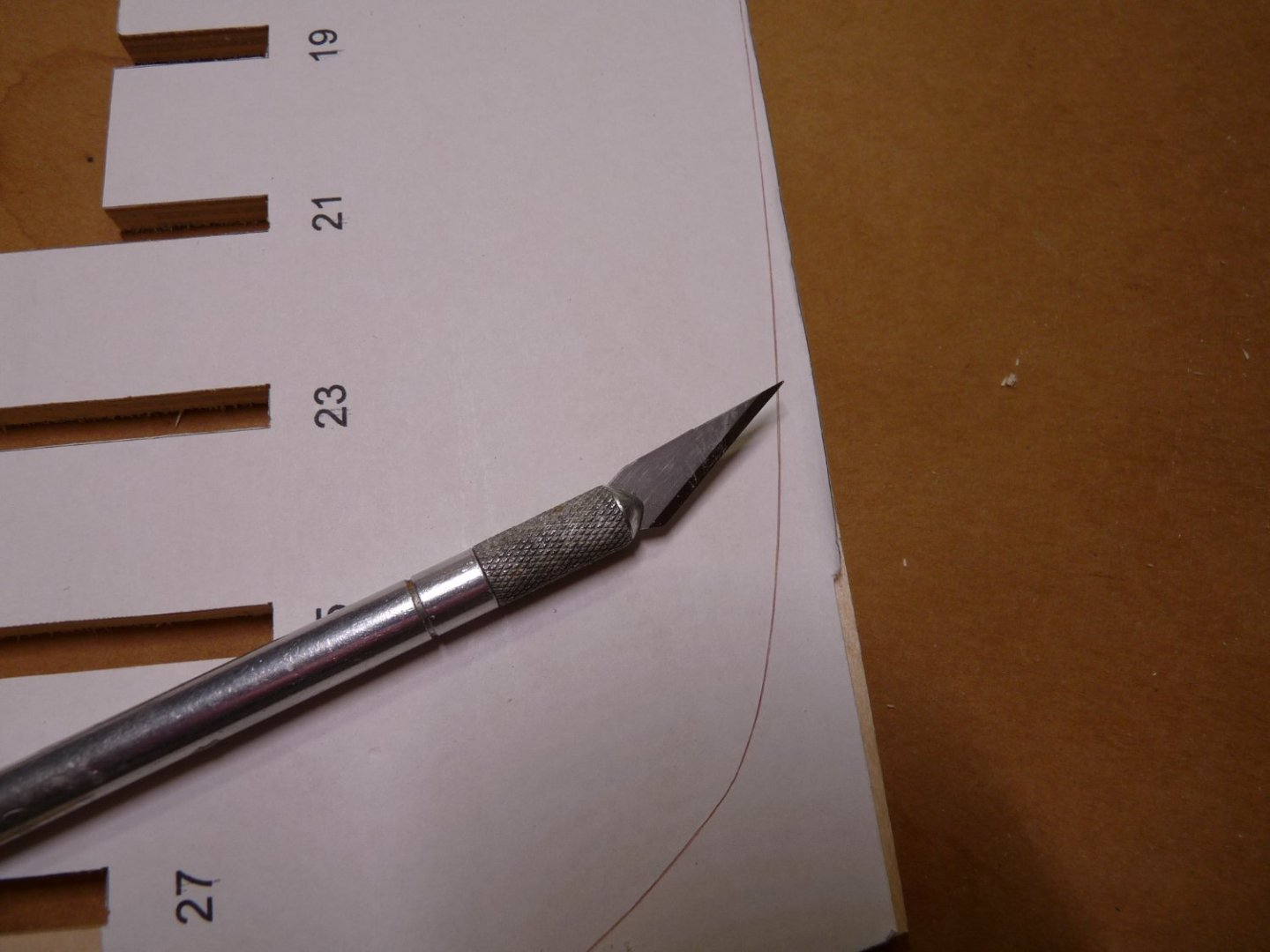
Early on I decided that I would try to make my own bulkheads and formers, mainly because it was a challenge to try to cut them, and also that it meant I could score a scroll saw! As I mentioned earlier, I bought a Wen 3923 16” saw. It is an entry-level saw, but just fine for my purposes. The first challenge was that it came with a bag full of parts for which there was no explanation nor instructions. I watched a few online videos on scrolling in general, and also on this saw in particular. For the unwashed, there are a couple of different types of blades - pinned and pinless. They each come in a variety of manufacturers, tooth type, tooth pitch, kerf sizes and blade widths. The pinned types are easier to change when you break a blade (and you WILL break blades), but generally are wider and have thicker kerfs as needed to allow for the attachment of the pins by the manufacturer. The videos showed a variety of uses; the most intricate cuts like fretwork, call for thinner (mostly pinless) blades, but for general use a wider blade is fine, and it doesn’t wander as much as a thin one. It turns out that the bag of parts that came with the saw is a conversion kit to change the pinned blade clamps that come with the saw to another attachment type that allows both pinned and pinless blades to be used. I have come to the conclusion, that – at least for work like cutting the bulkheads out of ¼” ply - the pinned blades work just fine, so I could have used the original blade attachment fittings. After playing with the saw using some scrap wood, I felt I was ready to tackle the bulkheads. Printing them should have been easy, but it turns out that my computer had other ideas. The patterns are included as part of Chuck’s download when you join. – they are presented as pdf files. I printed a few out on plain paper using my default pdf program, assuming (remember what Benny Hill said what happens when one assumes) that they would be full size, because I chose the “Actual Size” option that the program’s print routine offered. I then pasted them onto a piece of ply. I first tried using Elmer’s rubber cement to attach them. Later on, it turned out that several of them had not printed full size! They were off by quite a bit, but it wasn’t apparent until after I had cut them out and tried dry-fitting them to the bulkhead former. It seems that the old PDF routine that I was used to had somehow been replaced (and set as default) during an update without my knowledge by Microsoft Edge’s PDF routine. In the Edge program, the print routine doesn’t show the “Scale” option unless you click on the “More Settings” choice. You then can select “Fit to paper”, “Actual Size” or enter a scale size in %. You would think that “Actual Size” and 100% would give the same result, but it seems that that’s not true! In addition, when I left the program and came back later to print another bulkhead, the 100% scale size that I had entered previously reverted back to the program’s default 97%, and it wasn’t noticeable unless I chose the “More Settings”option. So, a cautionary word: check that your PDF print program is doing what you expect! The paper patterns worked ok, but was a devil to remove the rubber cement residue after removing the paper once the cutting was done. I had an old pack of Avery self-stick full sheet paper labels (8-1/2” x 11”) and tried them. They didn’t adhere to the wood very well, and tended to lift off of the wood during sawing. I rummaged thru my ancient stationary stock and found a pack of Brady Lasertab full size sheets. I don’t know where they came from – they must be over 25 years old. They worked beautifully; it turns out they are made of very thin polyester - not paper. I thought that I would order some more, but to my amazement they are now on the order of $7 per sheet from Brady! I’ll have to look into alternative polyester label manufacturers – now that I have used them all up it occurs to me that they may well be perfect for the friezes; they print nicely, are very thin and adhere excellently. The photo below shows one of these polyester patterns being peeled off after shaping the bulkhead. 8-1/2” x 11” paper works fine for the bulkhead patterns, but for those also cutting their own bulkhead formers, you will need larger paper for them. Legal size is perfect, but the price of paper has skyrocketed, and a ream of legal size paper is now about $30, if you can even find it! I solved this by going to the printing department at my local Office Max, and they sold me as many individual sheets of legal size as I needed at about a quarter per page. I took advantage of the straight edges of the 12” x 20” ply that I got from Cherokee and aligned the bottoms of the former patterns with the straight edges of the boards; it’s very important that the bottoms of the formers be as straight as possible for the coming attachment of the rabbet strip and the false keel pieces. We just can’t reproduce the accuracy of Chuck’s laser-cut formers when using the scroll saw, so using the cut edges of the ply sheets helps in this regard. Even after some practice, I am still no expert at scroll sawing, so I cut out the bulkheads leaving the pattern about 1mm shy of the finished lines, then finished the pieces down to the lines using my 1” belt sander and files. As I went along, I developed a sequence of sawing and filing that seemed to prevent damage to the upright bulwark extensions. These are the most vulnerable to damage while filing, so I made my first cuts along the insides of the bulwark extensions and along the top inside edge of the bulkhead. I also cut the slot that will go over the bulkhead former, being very careful not to cut the slot too wide I then u I then used the belt sander to trim to the final line wherever I could along the top and the inside bulwark extensions. Since most of these extensions have curves that are not accessible using the belt sander, they need to be finished off using files – I found that 8” second cut files work very well on the BB ply here, and filing in this area while still having a lot of meat on the outer run of the extensions reduces the probability of breaking one off. Then I went to work on the slots, carefully filing the cuts down to the lines, being very careful to keep the edges parallel to the bulkhead’s centerline. I used a scrap of the BB ply as a gauge to determine when the slot was filed to just a tight fit to the former. The former slots were handled the same way. Now the outer perimeters of the bulkhead were sawn and trimmed up on the belt sander. Several of the bulkheads have slots cut in them for the addition of the two sub-decks. Drill a hole to get the scroll saw started, and after cutting make sure that the bottom of the slot (upon which the sub-deck will lie) is filed smooth and has the proper camber. The last task is to transfer the reference lines that Chuck has provided on the patterns that will later be used to find the run of the wales and the gun port sills onto the finished bulkhead. This can be done easily by using a sharp Xacto blade and cutting right through the pattern down into the plywood. When the pattern paper is removed, the lines will be visible; just run a sharp pencil along them to make them visible. The bearding line needs to be transferred to the opposite side of the former, since only the starboard side line is printed on the pattern. After cutting through the line to transfer the bearding line on the starboard side, just remove the cut-off portion of the pattern and position it on the other side of the former and draw a line around it. Don’t forget to also transfer the bulkhead’s identification number or letter onto the proper side of the bulkhead. In anticipation of having to later find the centerlines of the bulkheads along their top edges, I used some quadrille paper to align them and then marked their centerlines across the tops. Then make sure that the finished bulkheads are a tight fit to the former. The tops of the bulkheads should lie flat to the top of the former; if not adjust the depth of the bulkhead slot to make it so. All the bulkheads should now be dry-fitted to the formers. Eyeball the run of the bulkheads and adjust any that are grossly out of alignment. At this point, I had not yet glued the three former pieces together.


-
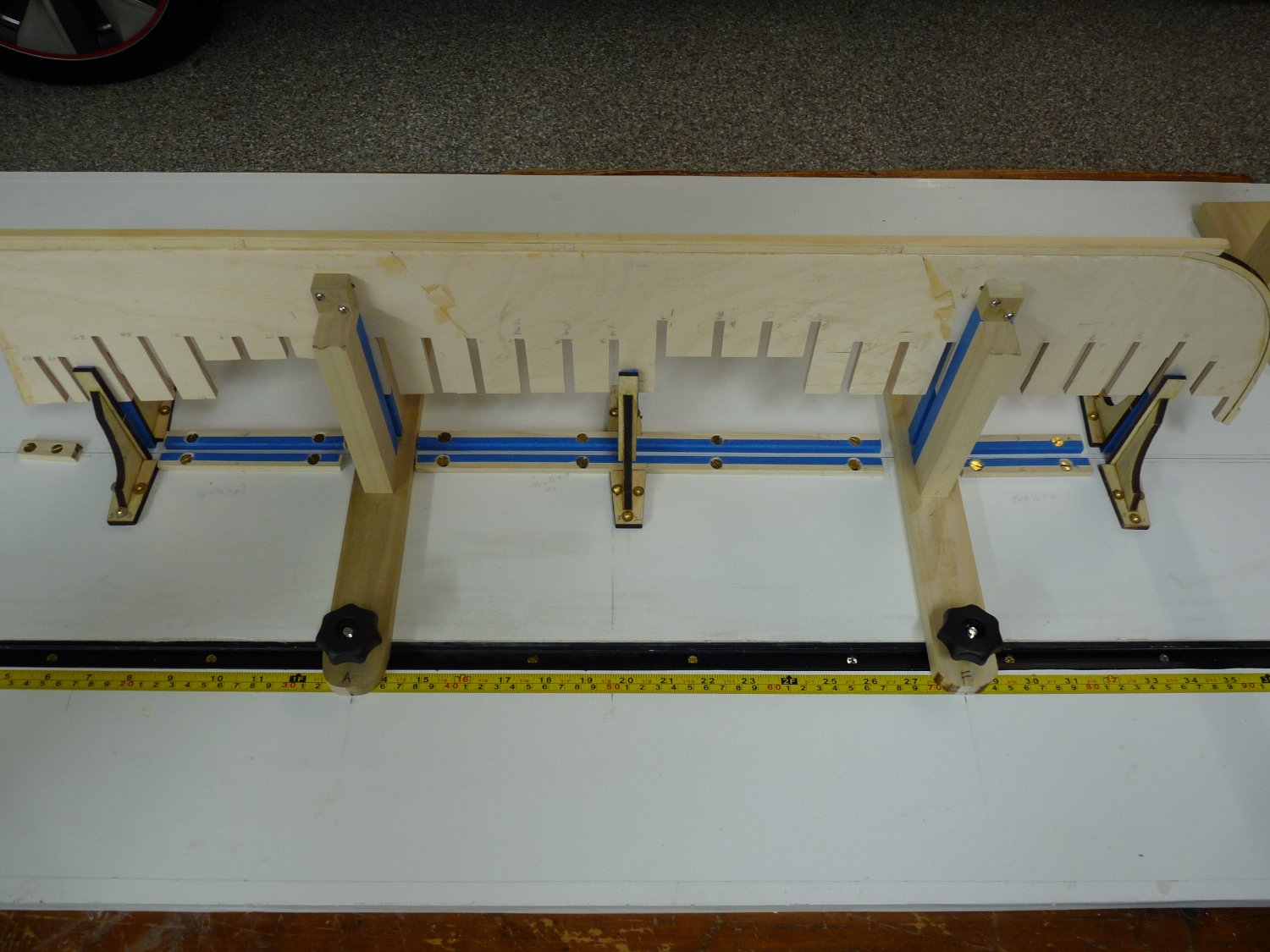
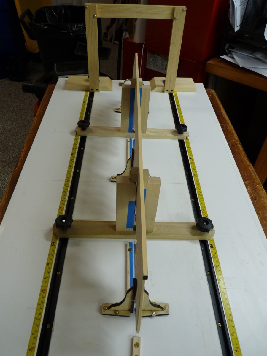
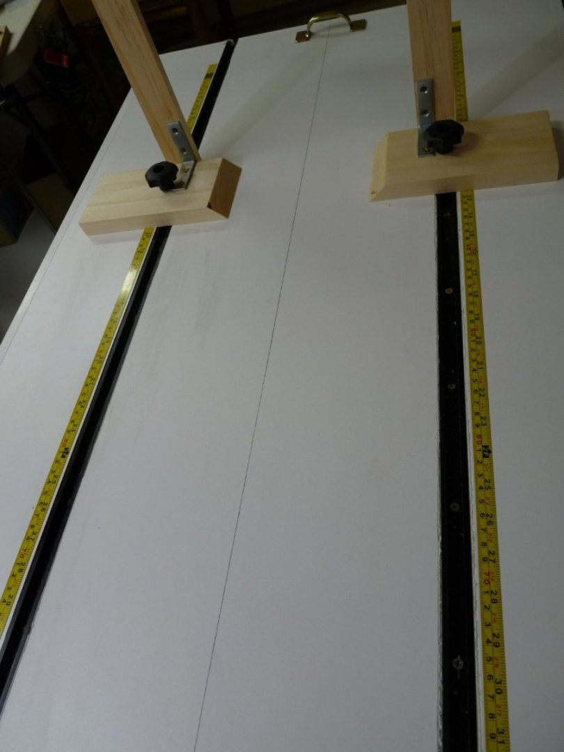
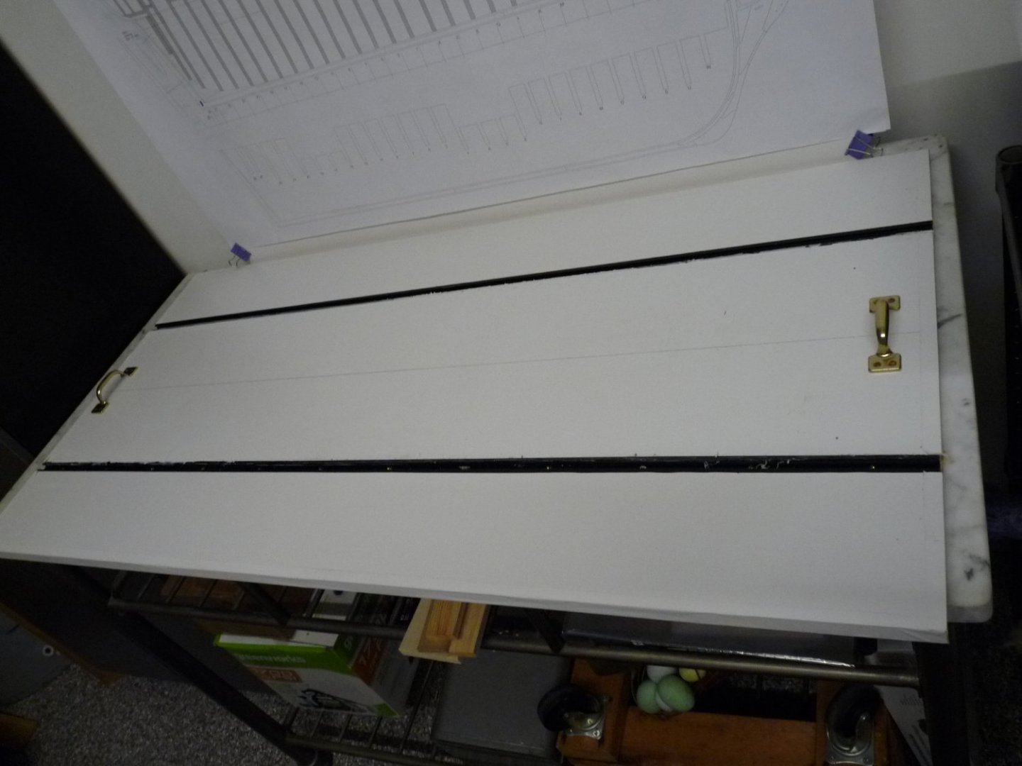
Got my Byrnes saw a few weeks ago, and she’s a beauty. Jim has created a work of art here. I’ve only played with it a little so far, but am able to consistently rip thin strips .020” thick from a ¾” thick sheet of poplar. Amazing accuracy and reproducibility. In the meantime, I cut out my bulkheads and the former from the ¼” Baltic birch with the new Wen scroll saw. I have some tips and comments for those who wish to go this route, but will save them for a future post; here I will document the progress on my build board. Sorry for the previous post, the order of the photos got scrambled a bit. After mounting the T tracks, I discovered that the routed groove on one side ran out quite a bit – about 3/16”, so I removed the offender and re-did the groove. Now the tops of both tracks sit just below the surface of the board and they are parallel over the 4’ length to better that 1/32”. The tracks are also parallel to the board’s scribed centerline to better than 1/32” over the entire length. This means that the gantry will be able to slide the length of the board without binding. The gantry’s purpose is to be able to check the positioning and squareness of the bulkheads as they are glued to the former. Since there needs to be clearance down the center of the build board because of the keel, etc, there need to be fiducials along the tracks to align the sides of the gantry, and to ensure that it is plumb and square. The gantry is made of some pre-milled poplar boards from Lowes; I used 1-1/2” x ½” x 12’ long pieces for the vertical uprights and 1-1/2” x ½” board 13-1/2 long for the top horizontal connector. The larger bases for the structure are from a 1” x 3-1/2” board 7” long. They each have a 45 degree bevel on the interior edge to clear any obstructions that are near the keel. The vertical clearance is 10-1/2” to miss the model’s highest point (transom), and the horizontal clearance is 10”; wider than the widest bulkhead + wale planking. The top bar is attached to the side verticals with machine screws; this affords a slight bit of movement to true things up. The verticals are attached to the bases with wood screws, and they are further braced up and squared thru the use of some angle brackets which were carefully measured and bent to precisely 90 degrees. After carefully checking squareness along all three axes, the screws and bolts were snugged down tight. Finally, the center of the top cross bar was found and scribed with a vertical line that is precisely above the longitudinal centerline of the build board. This will allow me to find internal center positions after the hull has been built up to the point that the interior is not accessible from the outside. One meter metal tape measures with double-sided tape backings were added along the outside edges of the T tracks to be used as fiducials for the aligning edges of the gantry bases. The tapes were carefully aligned with the 50 cm lines at the board’s longitudinal center line, and I ensured that they were exactly lined up with each other. Now, by aligning the forward edges of the bases with the same markings on the tapes, the front face of the gantry top cross bar is precisely aligned to be perpendicular to the board’s centerline. The center of that transverse distance can be located using a square and the scribed mark on the cross bar. A few coats of wipe-on poly were applied just to pretty things up a bit.


-
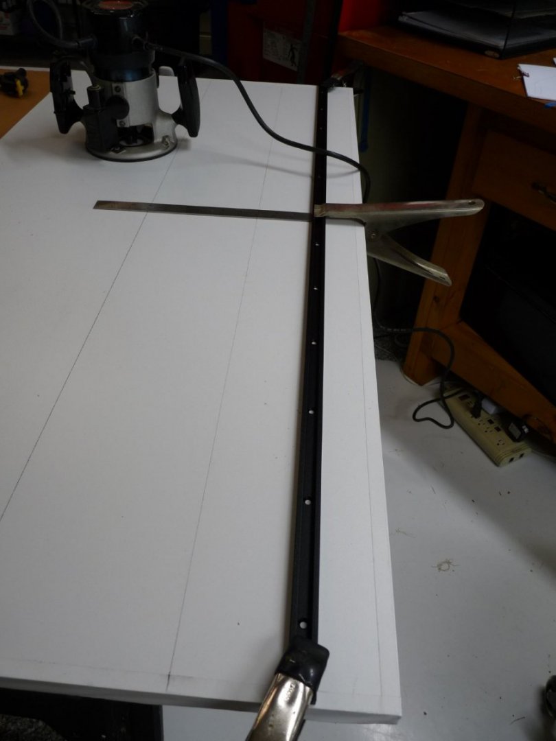
Still waiting delivery of my Byrnes saw, so I’ll just show a few rudimentary things for those who may be interested in following the way I am approaching the build. I’ll bet that there are several guys out there who would love to build Winnie, but are a little intimidated by the complexity. Relax – just jump in! Maybe some of these posts will encourage you to get started. First is the importance of a build board; I will need something dimensionally stable and accurately laid out upon which to assemble the model. I went to Lowes and got a piece of ¾” melamine-covered MDF, used for shelving. It is flat and fairly stable and thus suitable for a build-board. ¾” thick, 24” x 48” – about $17. Edges were rough – saw cut; I just covered them with some wide white tape. I am going to model my build board after Ed Tosti’s in his book on his Naiad build, although I don’t need it quite as elaborate. The build board will incorporate a gantry system that will facilitate precisely locating the keel and bulkheads, as well as being able to find interior centerline locations and dimensions down the road. I’m not sure that I need this level of precision, but it may come in handy for future builds. I then laid out and scribed a centerline down the long dimension and ran a permanent marker over the line. A swipe with an acetone-wetted cloth left a nice clean, thin mark to be used as a reference centerline. I then laid out lines 6” either side of center which will be the centers of two T-tracks to be embedded parallel to the centerline. I used the T-track, clamped to the board, (3” off the line in the outboard direction) as a guide for the router (which has a 6” dia. base) and routed two grooves ¾” wide by 3/8” deep to take the T-tracks. The board is pretty heavy (24 lbs), and I will need to move it around often in my crowded garage workshop, so I added a sash handle at either end to facilitate moving it. Once the planking has been completed, the model can be moved to a smaller board for most of the remaining work. The construction of the gantries and other measuring devices, a la Tosti, will have to wait until I have received my Byrnes saw. I will probably make them from some pre-cut poplar wood billets available from Lowes or Home Depot.


-
Hello folks; I’m Ted Robinson and I’m just beginning my build of Chuck’s fabulous Winnie! I have been watching him develop the model over the last few years and have been salivating over starting my own build, but had to force myself to finish my Caldercraft Victory first. Vic took an elapsed time of 11-1/2 years and 5,400 hours, and I knew that if I stopped the build to begin Winnie I’d never get back to her, so I persevered – but it has left me 3 years behind most of the rest of you. I finally pulled the trigger and signed up for the group build a few weeks ago. I have read and enjoyed all of your postings and photos of your builds, and hope that I can do justice to this fine model. To begin with, I’m going to listen to Chuck’s advice and make most my own parts that are not precision laser cut by Syren, such as the bulkheads, keel formers and most of the planking. This of course gives me an excuse to buy a scroll saw and most of all a Byrnes’ saw! There may not be many others who join after me, I’m pretty late to the party! But, I have noticed that many of the build logs of the more experienced modelers here have not mentioned a lot of the prep work that goes into making a model of this size and complexity, so for those who come after me, and while awaiting my Byrnes saw, I will post some stuff on the pangs of getting started. As I said, I have decided to make my own bulkheads, etc. and so to begin I needed 1) the plans, 2) plywood and 3) a scroll saw. 1) The plans were easy, just follow Chuck’s instructions here and sign up – he will give you permission to download all the necessary plans. After getting them downloaded, I needed to have the 4 large drawings printed out full size. I tried Staples and Office Depot, but in the end I went with a local printer that I found on the internet under “blueprints”. Just took the flash drive with the 4 files on them to her and asked for 100% prints; they are about 30” x 40”. She questioned me about copyrighted material when I called to find out if they could print them, and I texted Chuck who sent me an email allowing the printing, and all was OK. Cost was about $2 each print. Got a large piece of foam board from Michael’s framing department to mount them on with binder clips. 2) I looked on the internet for suppliers of Baltic Birch plywood. There are lots of vendors out there; I went with Cherokeee (for no particular reason), and ordered a 5’ x 5’ sheet of ¼” BB ply cut into 15 each 12” x 20” pieces. It wasn’t until after I had already purchased the ply that I read several peoples’ admonitions about using BB ply, as it is harder to sand and shape during fairing. Oh, well, live and learn! Cherokee actually sent me the wrong size ply the first time (1/8” rather than ¼”), but quickly replaced it at no cost with the ¼” after I called. They even let me keep the 1/8” since the shipping to return it would have been prohibitive, I guess – so I now have a lifetime supply of nice 1/8” Baltic Birch ply! 3) As for the scroll saw, I looked around, and not wanting to sell the farm to get a top-of-the-line model, decided on the 16” Wen 3923 from Amazon. Although I usually will spend the extra money for good tools, I reasoned that at my age I might not get much use from it after making the bulkheads and formers for Winnie, so opted for the Wen. More on the saw, build board etc. next time. Happy to be here with all of you!
-
Thanks to Allan and Phil for your likes. Yes, Allan, I'm starting on Chuck's HMS Winchelsea. It is an outstanding model, and I hope that I can do it justice. It's a kit (sort of) but not like you would buy from Amati or Artesania Latina, etc. Chuck has developed this from an outstanding museum model. It's an ongoing labor of love for Chuck; he's developing the parts as he goes along, making laser cut parts for those who want to follow his build. He stared it about 3 years ago, and there is a group build going on with dozens of modelers contributing. I'm really late to the party for the group build, but it gives me the advantage of seeing how others have fared with different aspects of the build. If you're not familiar, I urge you to look here at MSW for the group build logs. I'm going to try to make many of my own parts like the planking and bulkheads rather than buying the pre-cut versions. I'm hoping to gain some new skills by doing this; it also give me a great excuse to buy a Byrnes Saw!!
-
Now that I have essentially finished Victory, I am taking some better photos to send to the Gallery portion of the MSW, and in the meantime I'll post a few here for those interested.


-
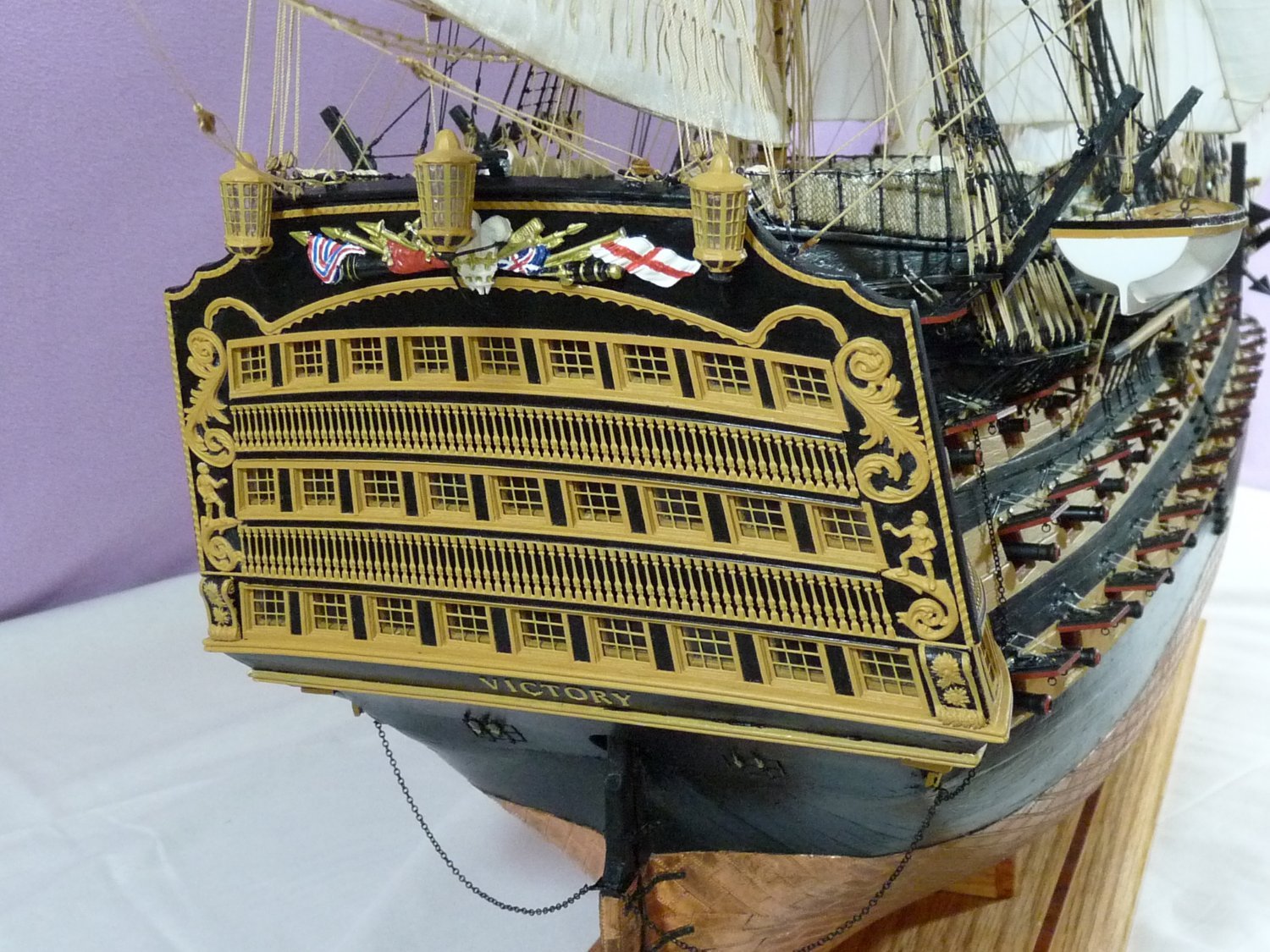
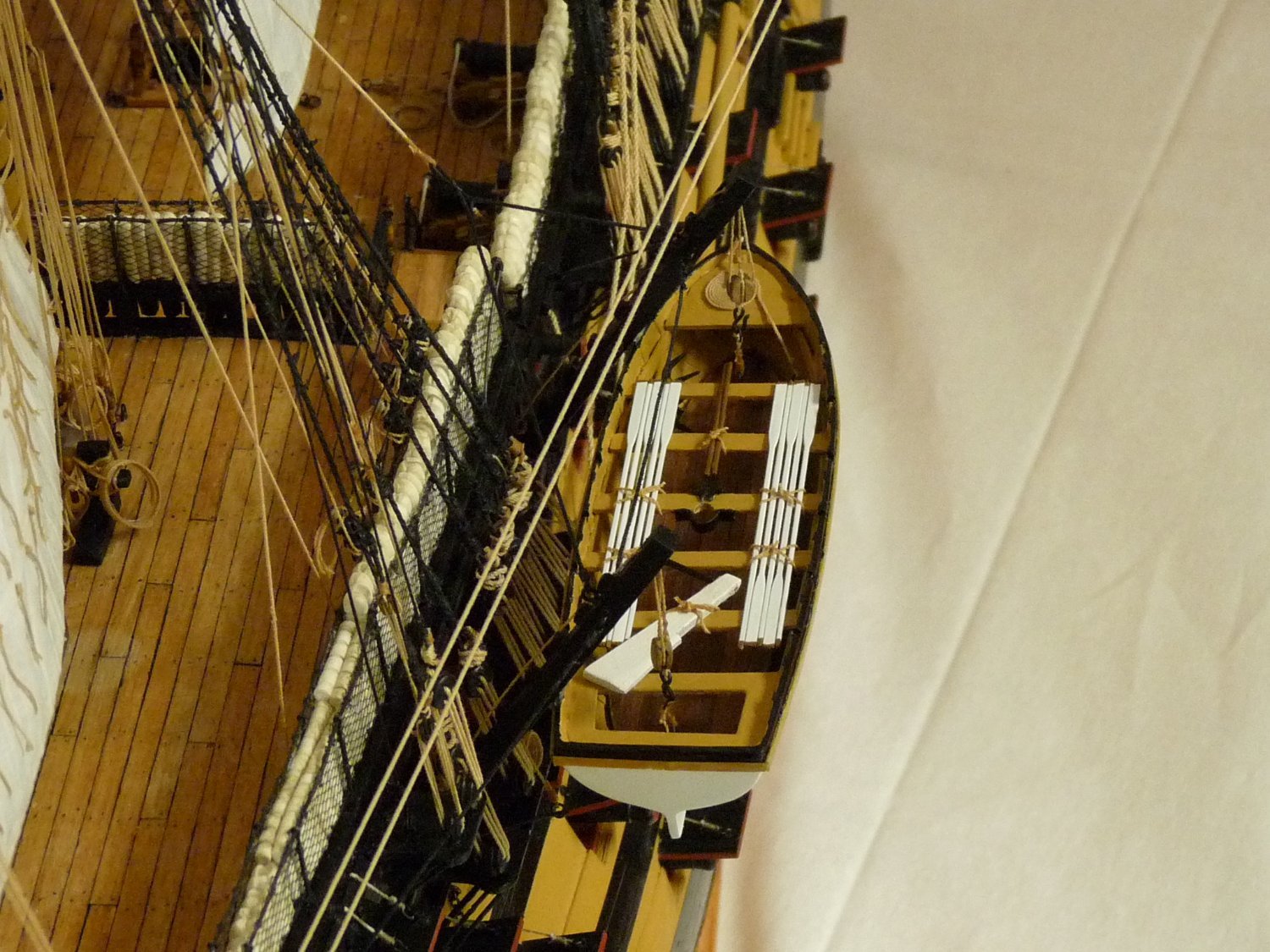
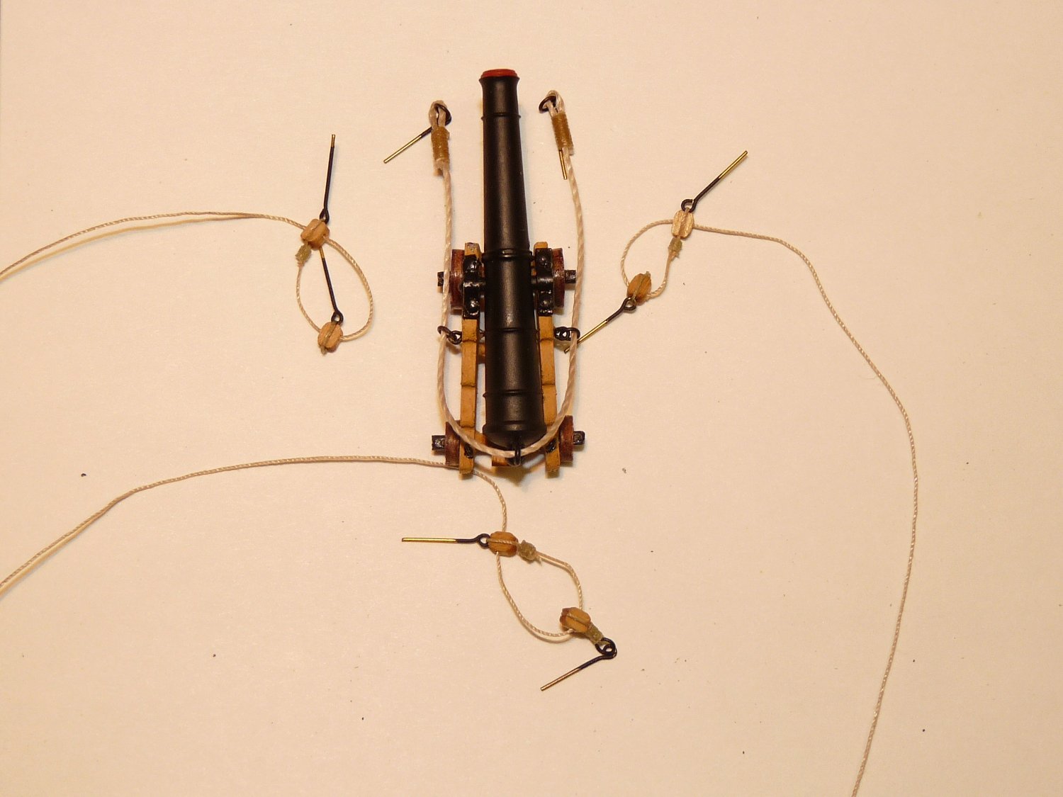
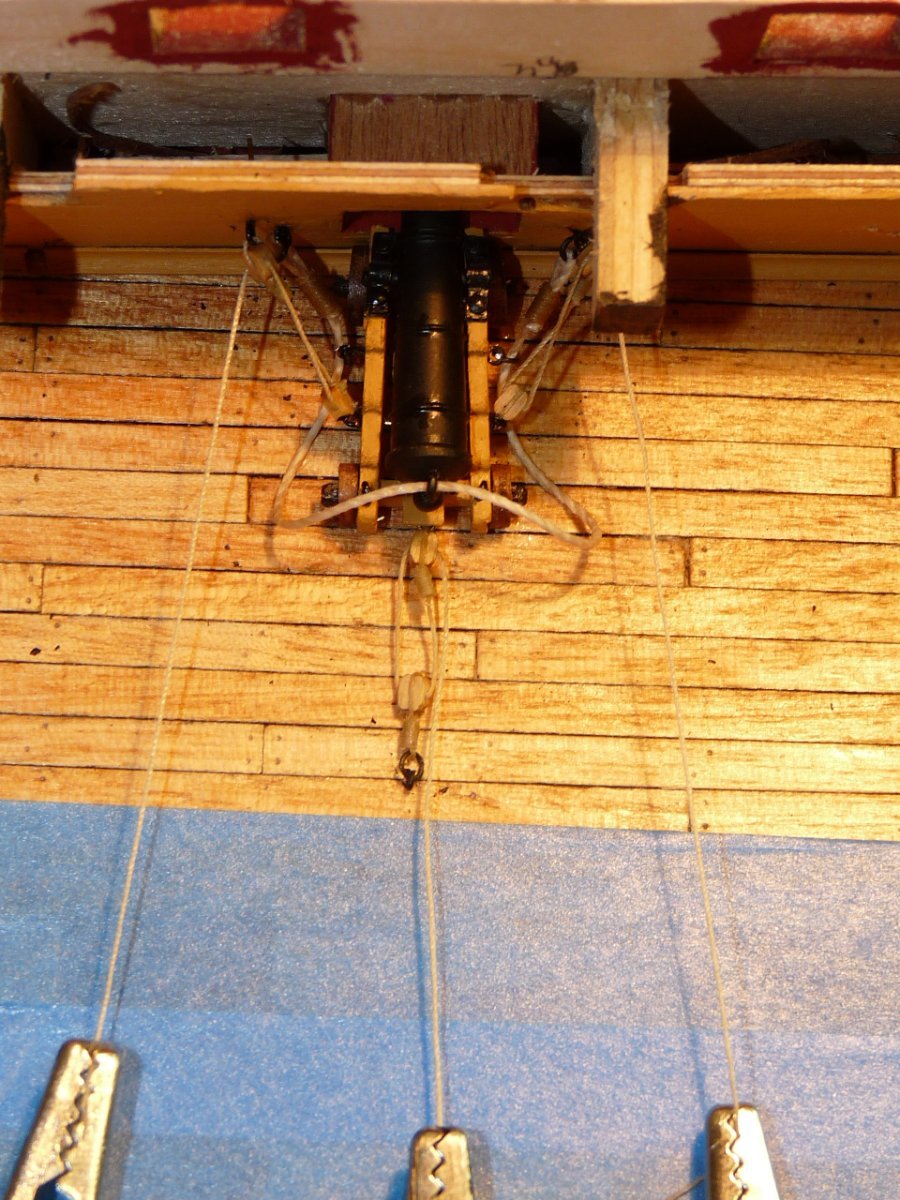
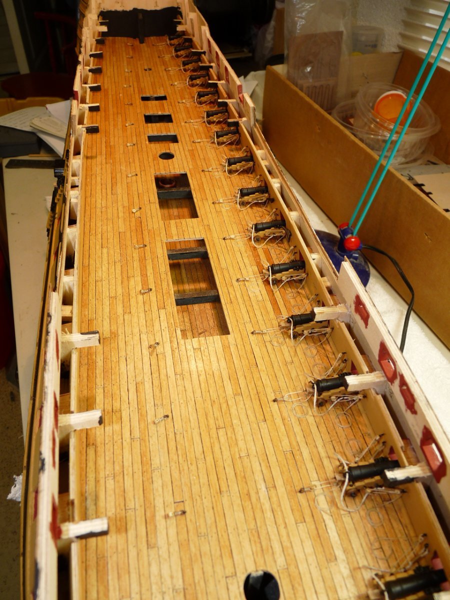
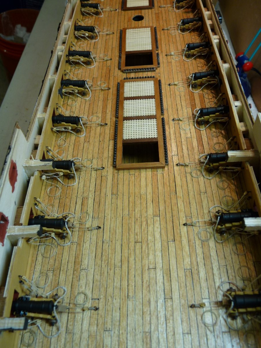
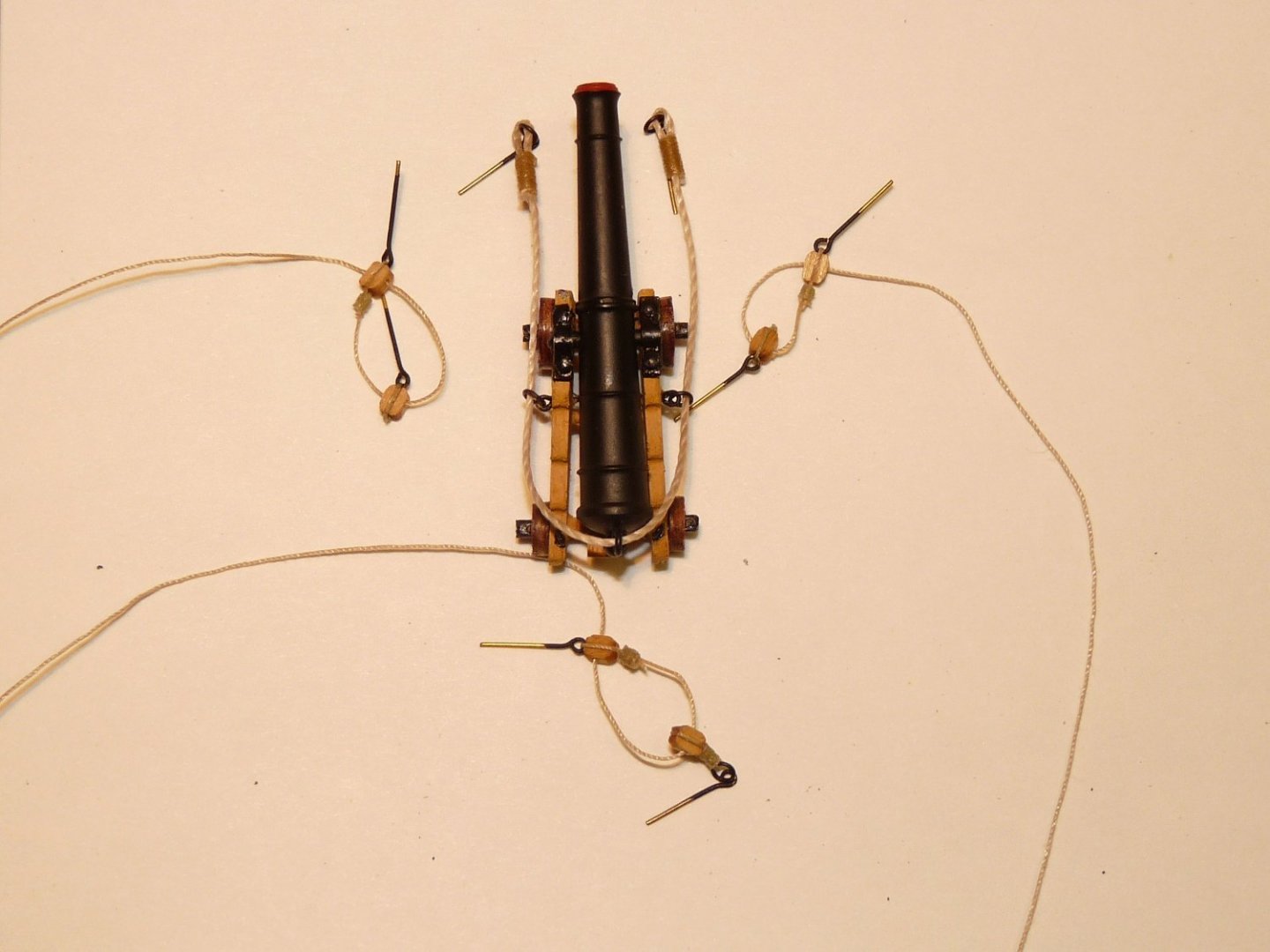
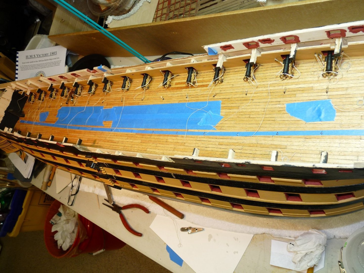
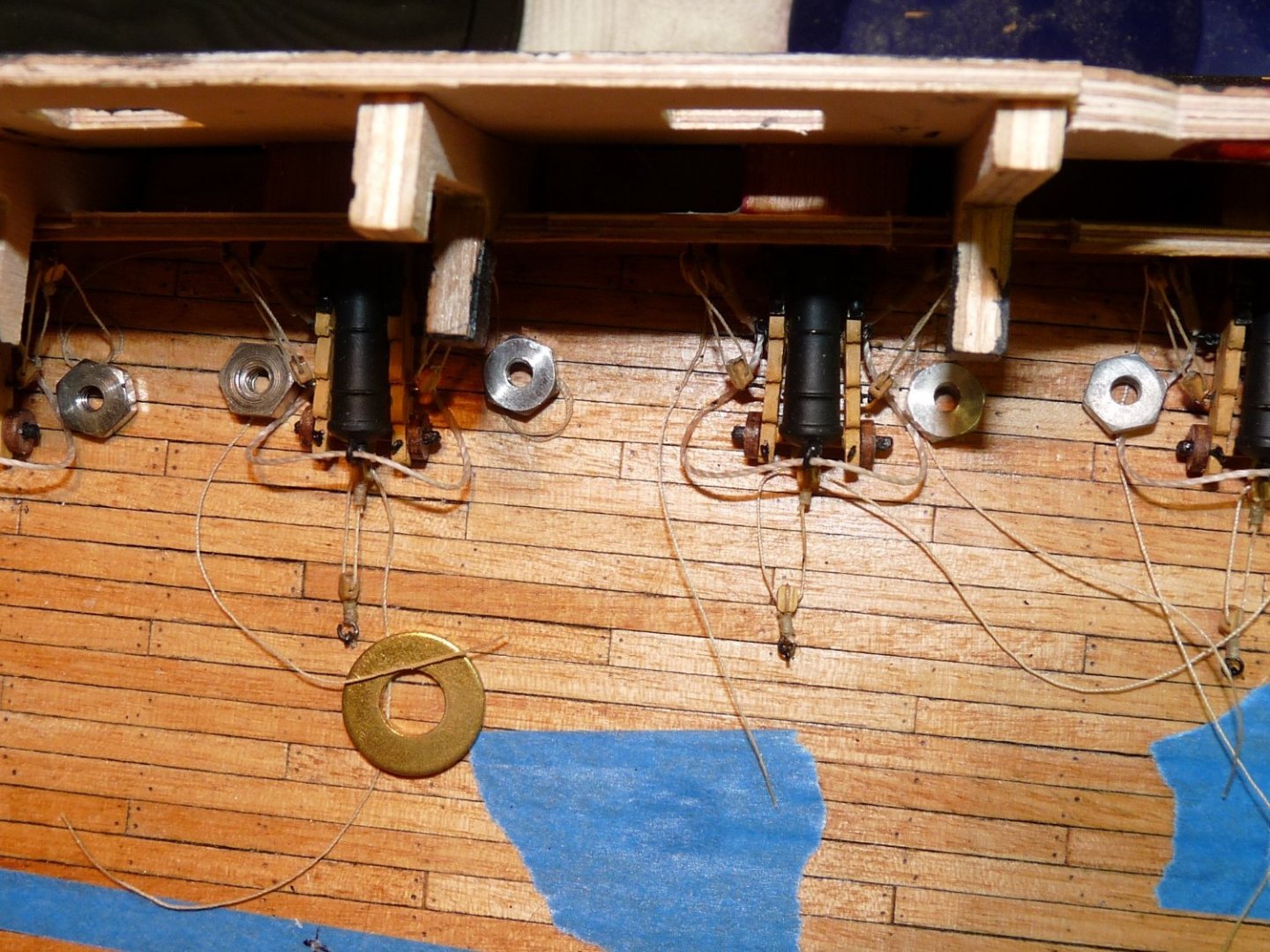
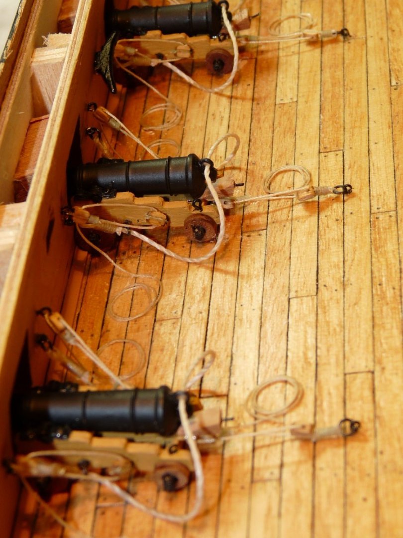
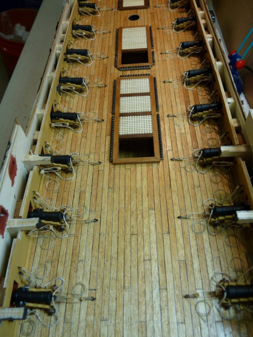
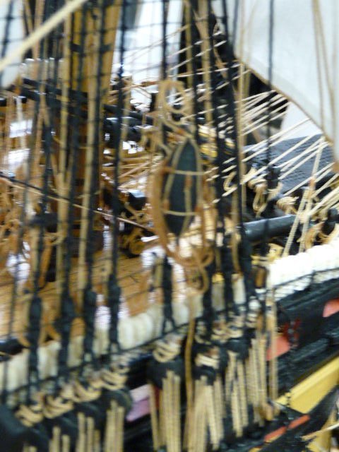
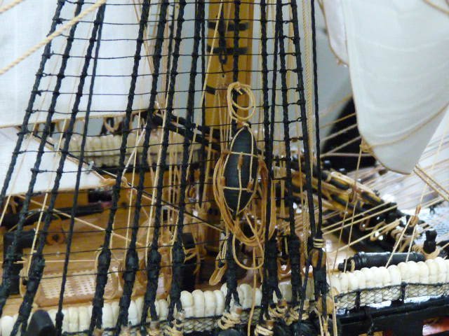
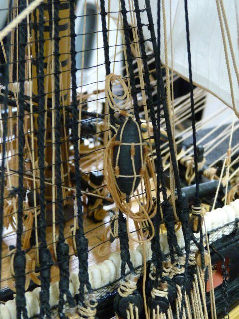
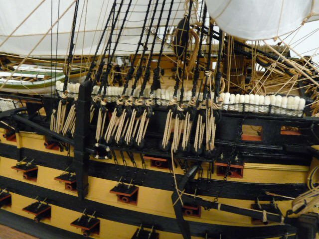
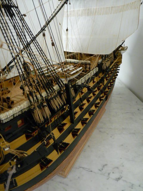
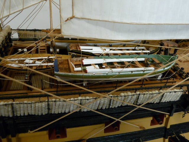
Thanks to all who have replied - Allan, Phil, Malcolm nd Cisco. Allan, thanks for noticing the gun rigging. Caldercraft’s version of Victory includes 32 each 32 pounders for the lower gun deck (dummy guns – barrels only), 30 each 24 pounders for the middle gun deck (again, dummy barrels) and 30 each 12 pounders (carriaged) for the upper gun deck. The quarterdeck, admiral’s quarters and foc’s’l all have additional 12 pounders of different lengths, also carraiged. Then there were a couple of carronades at the foc's'l. The upper gun deck guns are all rigged in place, even though they are not at all visible on the completed model. The other weather deck guns are similarly rigged, and are the only ones still (slightly) visible among the sails and rigging. I know I’m a little anal (well, maybe more than a little), but I just had to rig all 30 of those UDG guns in place! Here are a few shots of the process from 2012 when I was at that stage of construction. Note that the blocks used for the gun rigging were those supplied with the kit, prior to switching to the Syren blocks.


-
Thanks to Allan and Phil for your kind words. Yes, the blox that came with the Caldercraft kit were pretty terrible, so early on I decided to spend a little to have them look period correct, so I bought them from Chuck at Syren. Stained them, opened the sheave holes and stropped each one according to size. The very large sheaves, such as the jeer and anchor cat sheaves, as well as some 7 mm and 9 mm items were scratch made. I'm glad I went with Chuck's blocks - they make a great difference IMHO. I have been drooling over Chuck's Winchelsea for a couple of years now, but pushed myself to finish Victory first. Am now jumping in with Winnie; have ordered a scroll saw and will be trying to scratch-build as much of her as possible. At 83, I don't even buy green bananas anymore, so I must be nuts to take on the Winnie, but full steam ahead!! Ted
-
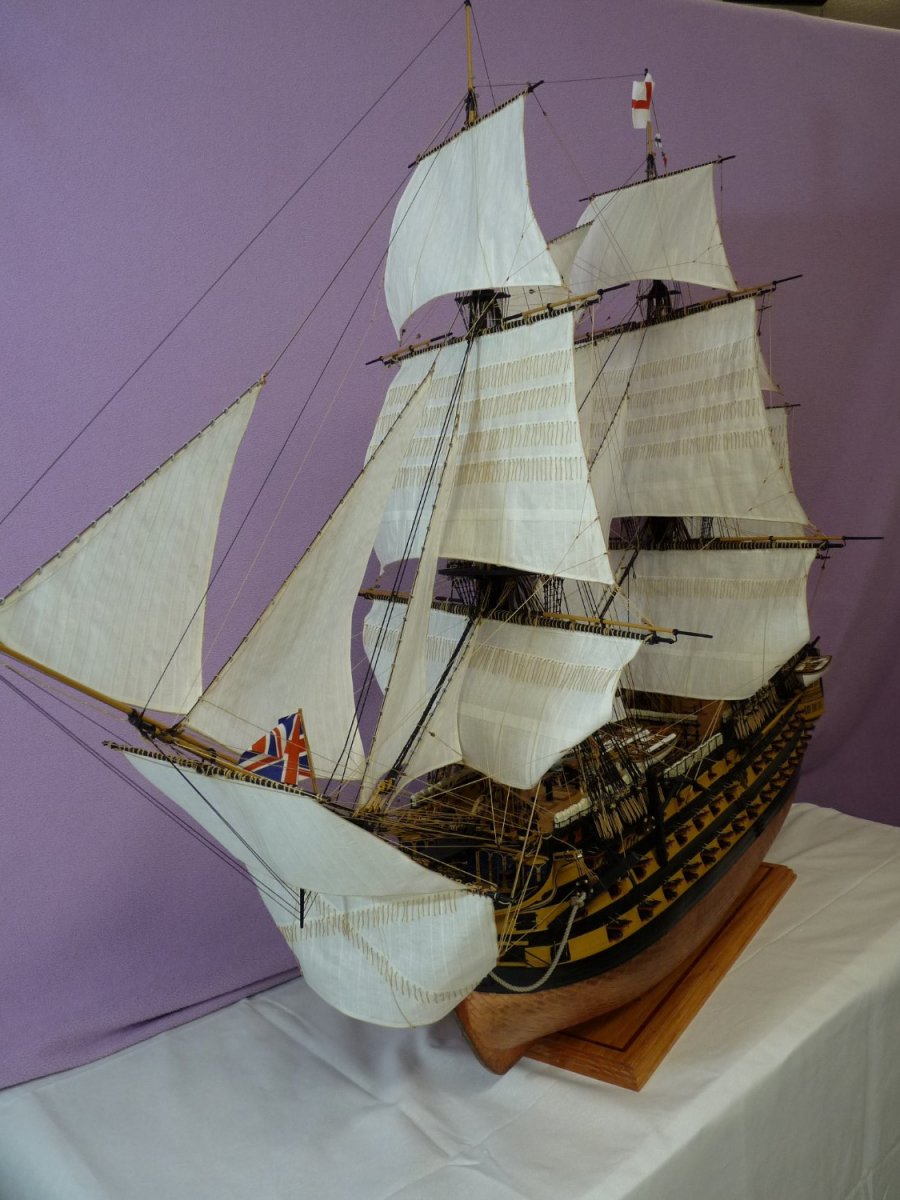
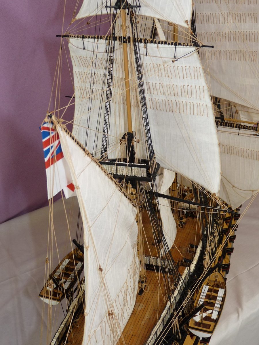
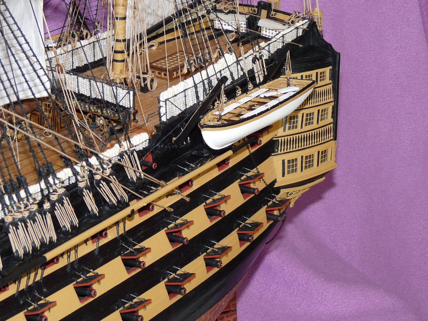
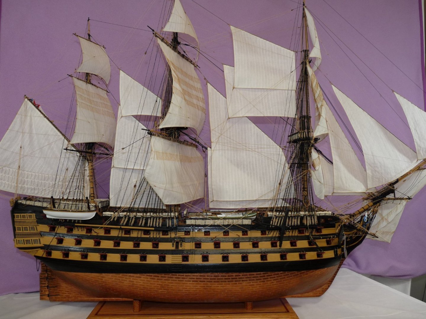
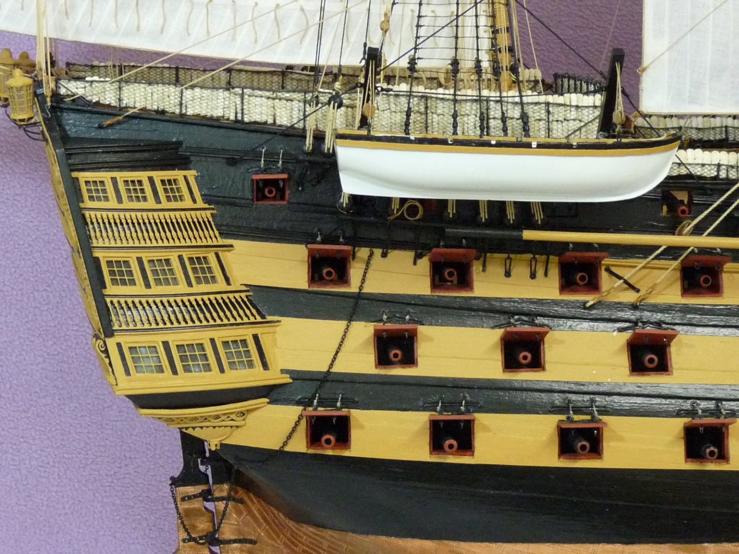
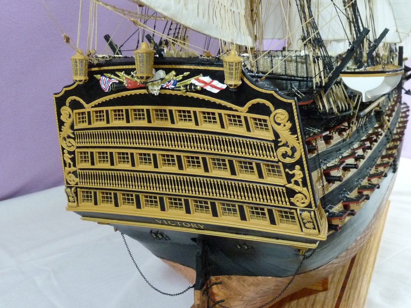
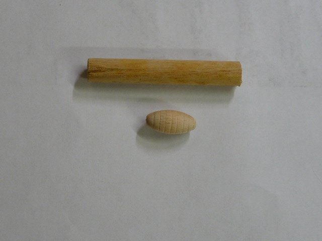
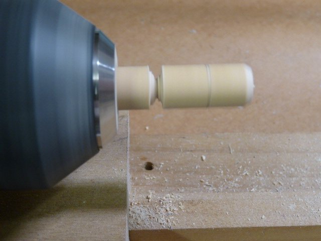
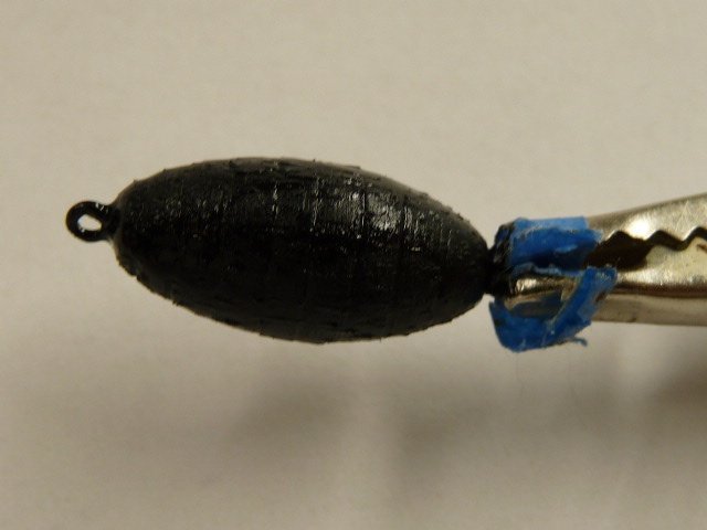
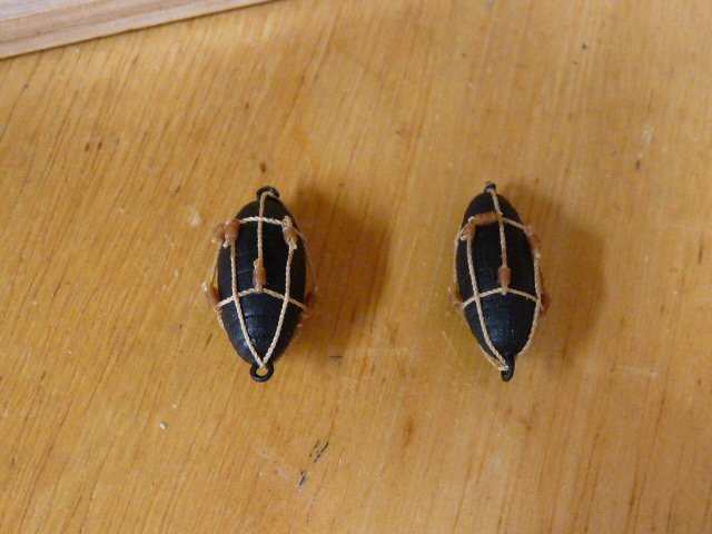
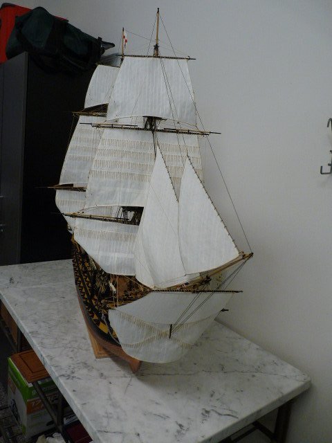
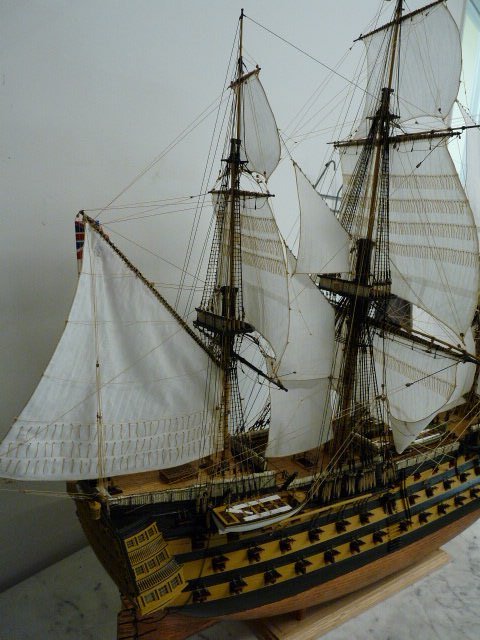
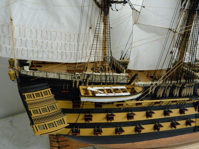
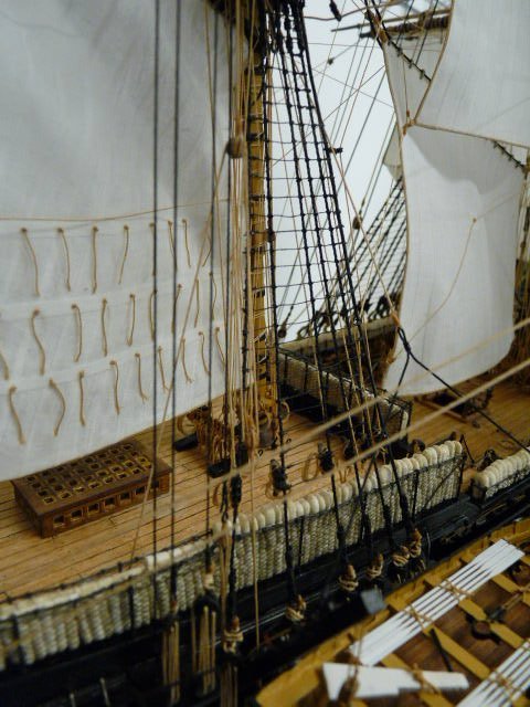
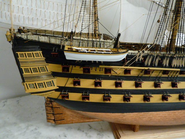
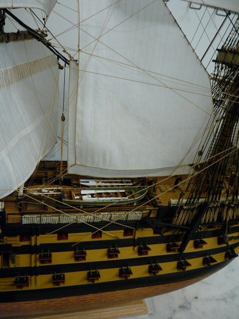
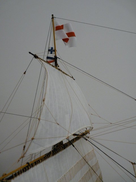
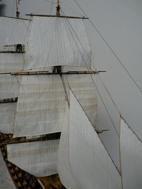
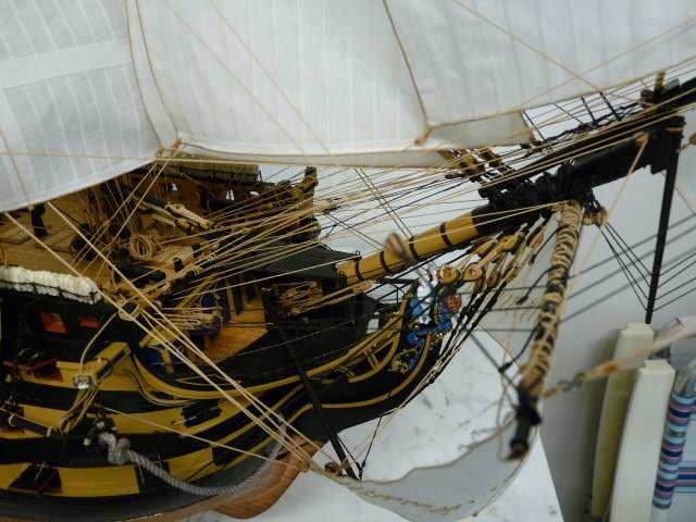
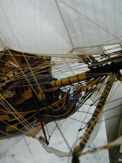
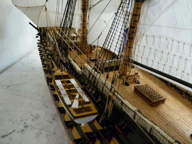
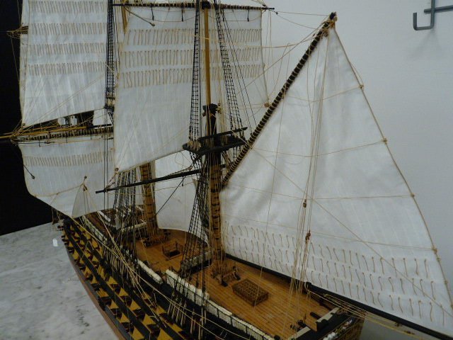
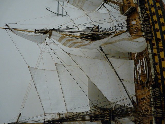
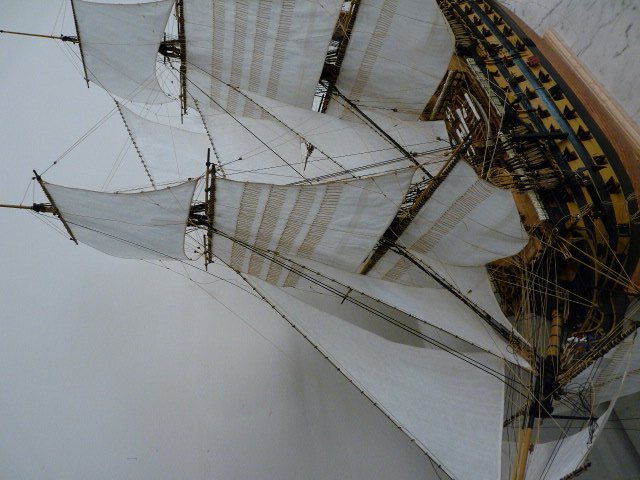
Finally finished my Victory, after 11 years and 5 months (including about 5 years of inactivity) and 5,400 hours of assembly (not counting endless hours of research, spreadsheet construction and rope-making). Here are a few quick snapshots of what she looks like, I apologize for the quality of the pix. I will do a much better photoshoot in a few weeks when I get the proper equipment, and then post them to the gallery for those interested. First, a few shots of the final task; the anchor buoys. Turned from a short piece of 1/2" dowel. Now for the shots of the final results As soon as I get some decent lights and a backdrop I will take better pictures to post here, and also open up a gallery folder. Thanx for looking! Ted

-
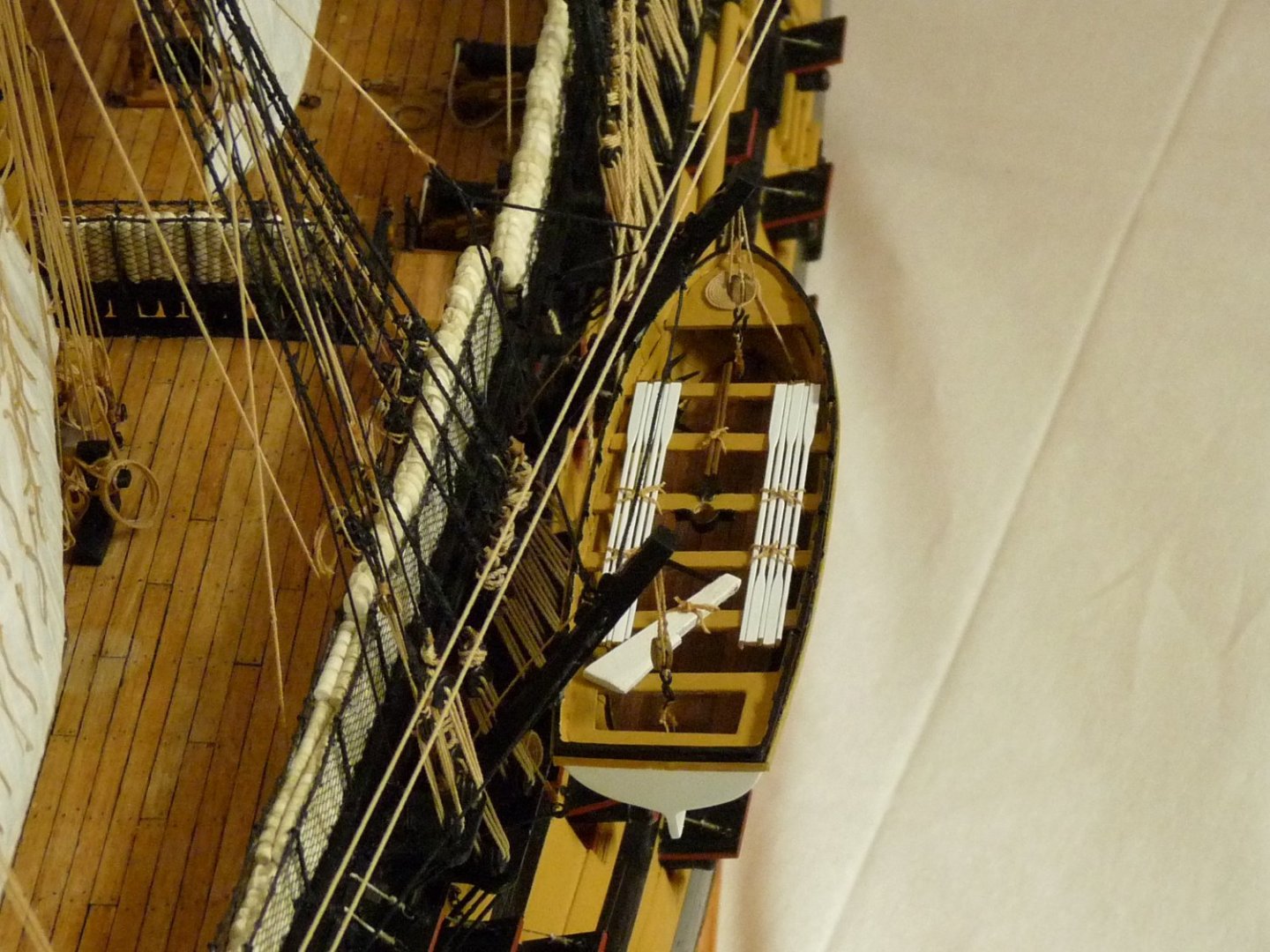
Here are a couple of snapshots of my Victory. I apologize for the quality of the photos; the background is less than ideal. I have added a few more sails - the most recent one being the mizzen topgallant staysail. Only one more sail to go - the flying jib, which will be added after I ship the flying jibboom at a later date. There are still a lot of un-tensioned lines such as braces and bowlines, and I have to still rig some backstays. I'm presently working on a couple of additional launches to hang from the davits. Sorry about the last 2 shots - I haven't been able to find a way to rotate them.


-
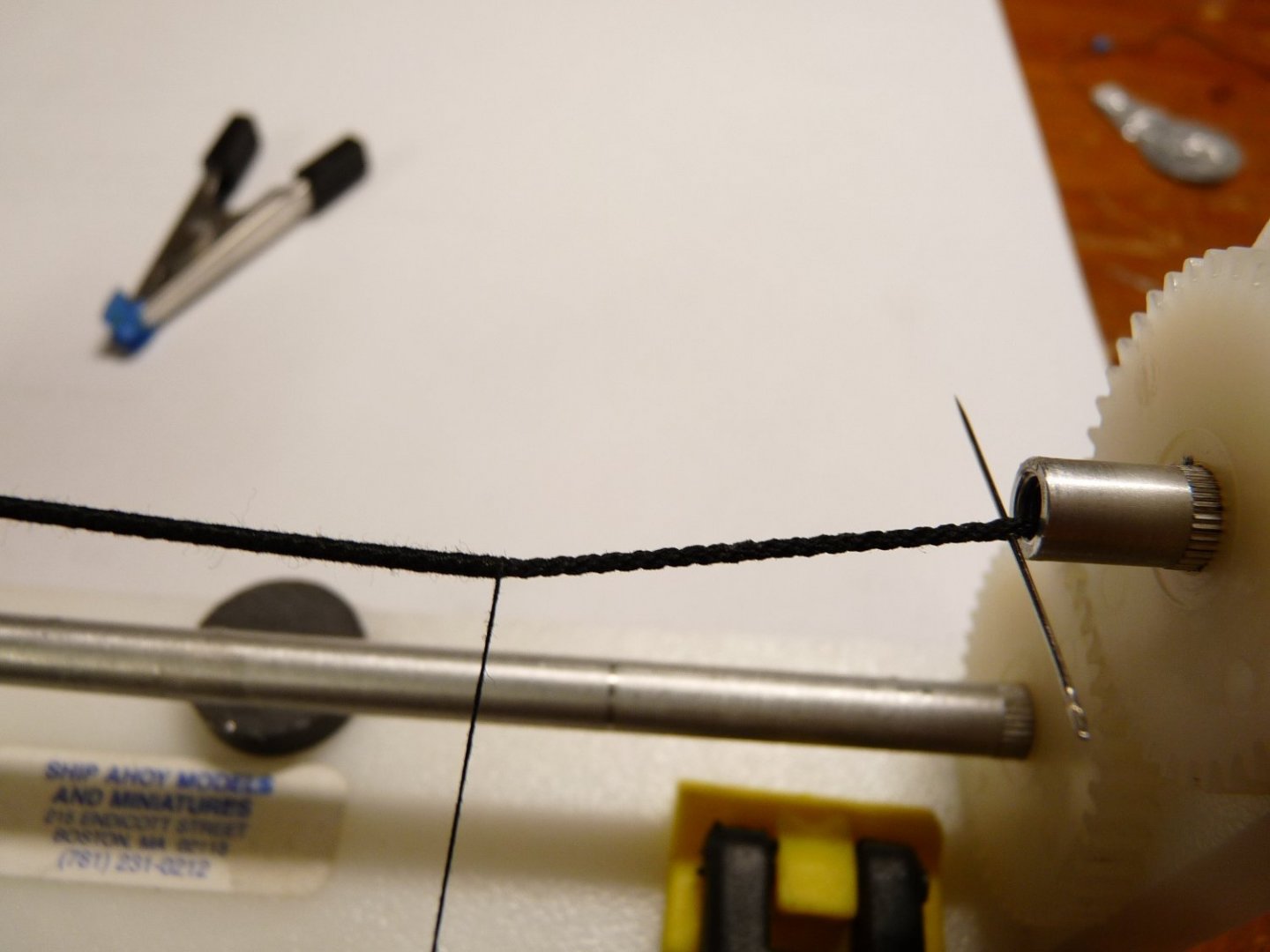
I use my old Ship Ahoy serving machine to apply my service. I have served lines down to .012" in diameter. I first make sure that the rope to be served is very taut between the ends of the machine. Being right-handed, I always serve from left to right. I know, the old ditty is "worm and parcel with the lay, turn and serve the other way", so it should make a difference whether the rope is left- or right laid, but at small scales it's impossible to tell the direction of serving on the final product. I determine the starting point at the left end of the rope and, with a very sharp needle pierce the rope there. Thread the serving thread thru the needle's eye and pull it thru about 6"; use a small piece of tape to lightly secure the end of the thread to the served rope off to the right.. Now I locate the other end (the finishing end) of the service, and again pierce the rope with a needle at that spot and just leave it there. Start the winding, packing the thread turns closely together until you have about a dozen turns laid up. This will have secured the bitter end of the thread under the first few wraps of the service, and the thread's end can now be removed from the tape and cut off as closely as possible. Continue serving until you reach the second needle. Cut the thread about 6" long, and thread it thru the needle's eye. Pull it thru the rope to secure the bitter end. Now apply a small bit of PVA (Elmer's) to the whole served line, and rub it in so it penetrates all the turns. It will dry in about 5 minutes, and will afford some protection from the whole thing unravelling if it is nicked with a knife or sharp edge later on. After the glue dries, trim the bitter end of the thread off as close as possible. Voila! A served rope! Note, if the length to be served is longer that the serving machine, making it impossible to insert the second needle, just quit when you approach the right hand end of the machine. Put an alligator clip near the end of your service, it will bank against the machine and prevent it from untwisting when you release the rope from the clamps at either end. After releasing the ends of the rope, carefully pull the rope to the left until it is repositioned where you want it. After the rope is taut again, remove the alligator clip and continue the service. Repeat until you have reached the end of the service length, then insert the right hand needle, and finish as above.
-
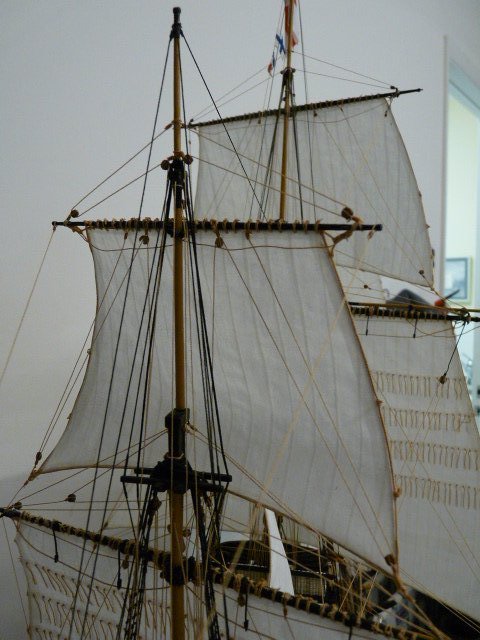
A few more sails have been added to the model. Most difficult was the driver - lots of competing tensions on the sail and spar lines. The mizzen topsail and the mizzen stay sail have also been hung and the lines run, but they are not yet tensioned More pix of them in a few days when they are completed. Then on to the final stages; the addition of the topgallant masts, spars and sails.


-
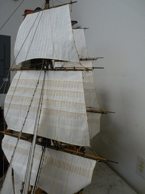
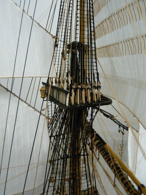
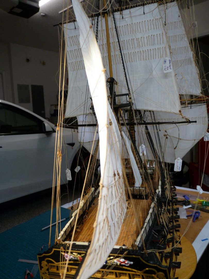
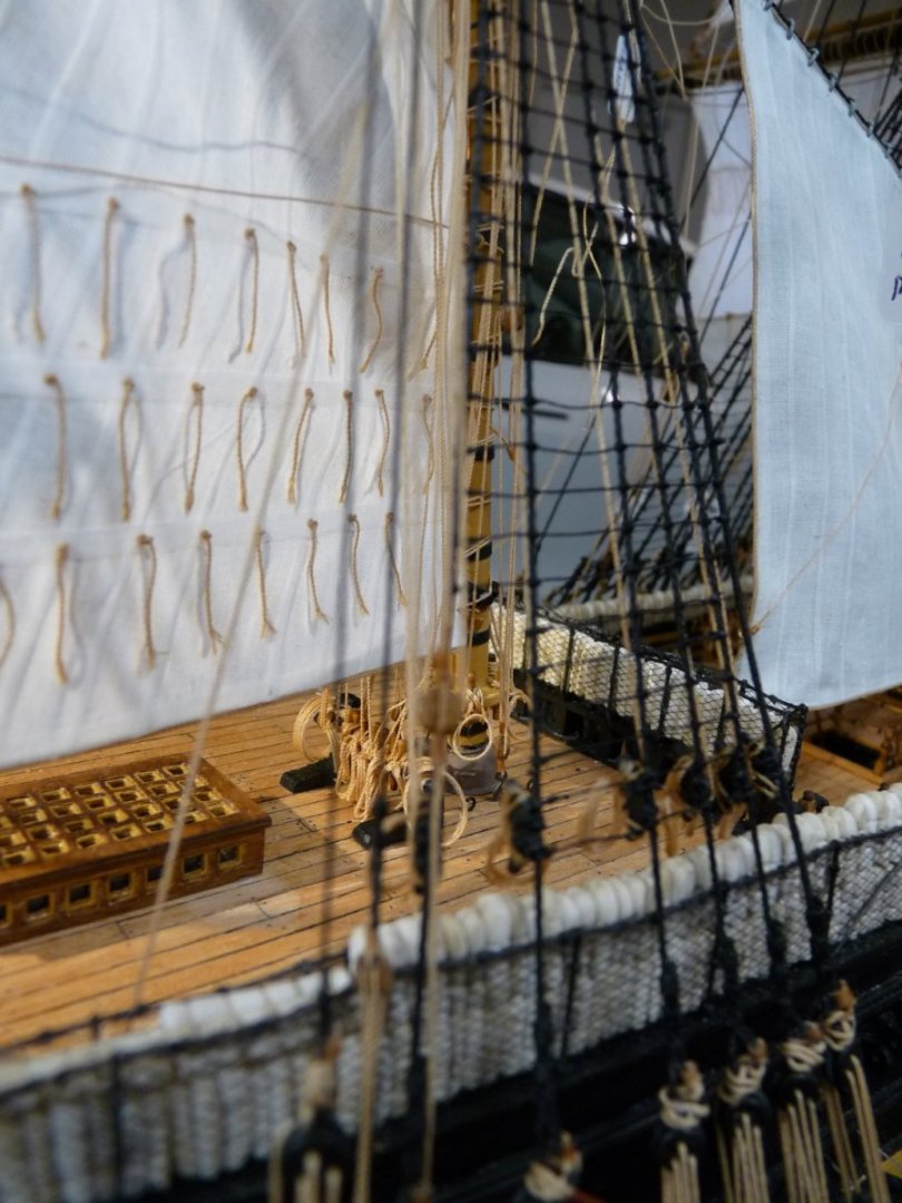
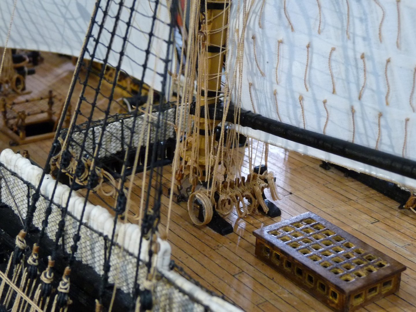
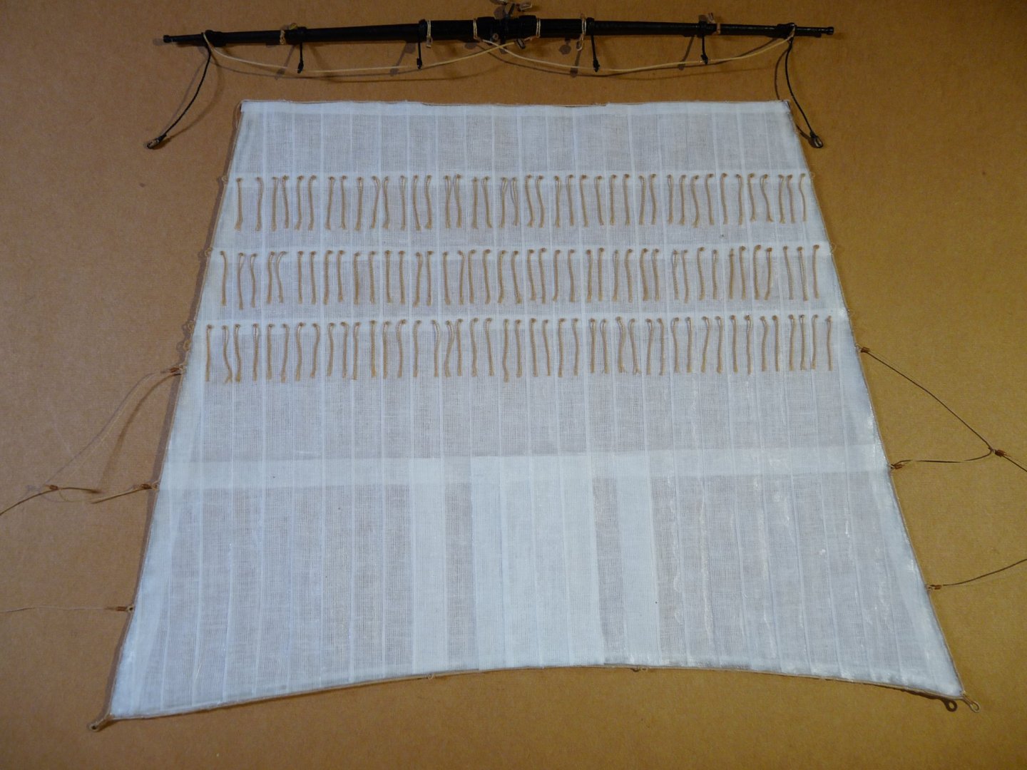
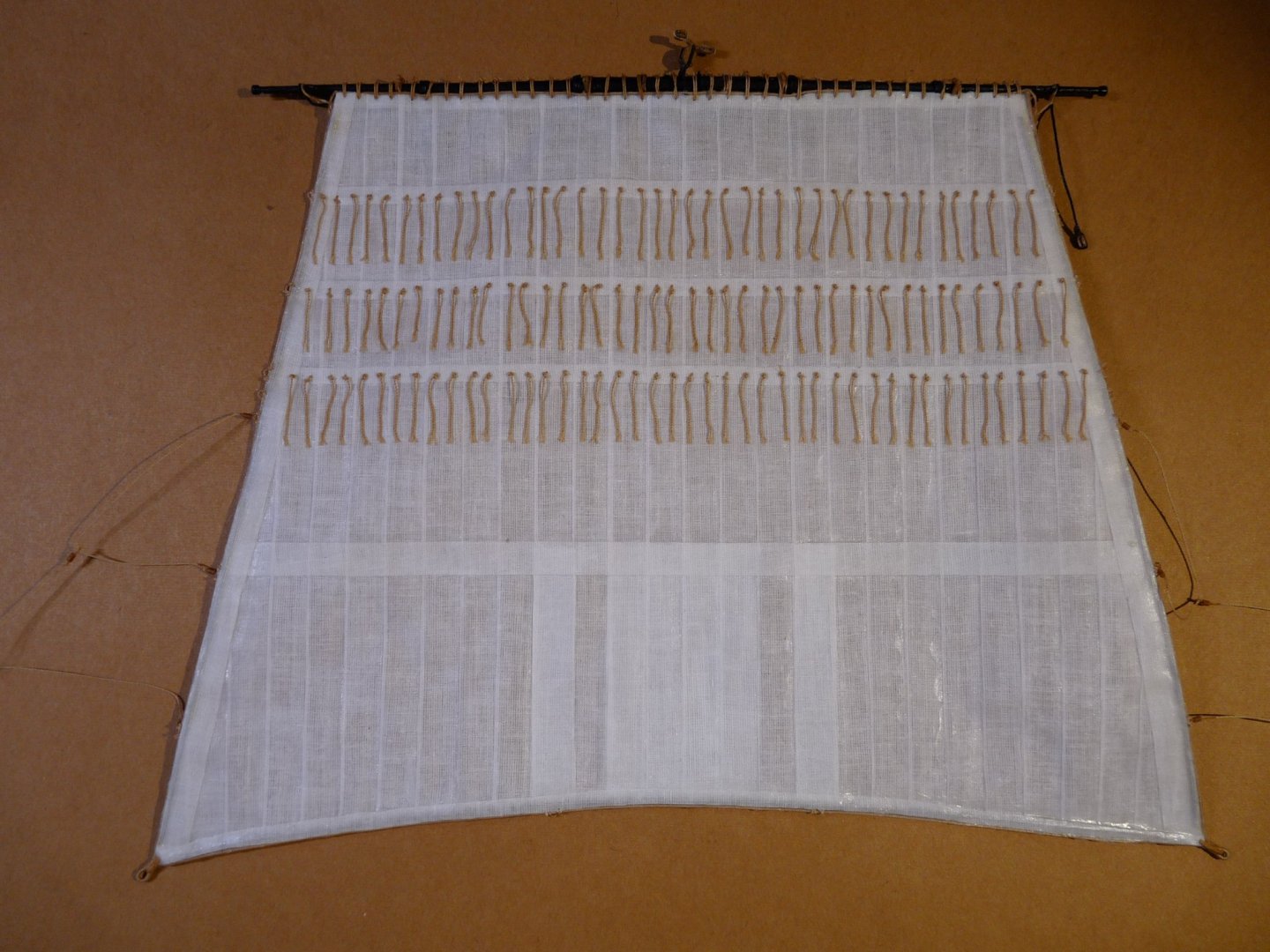
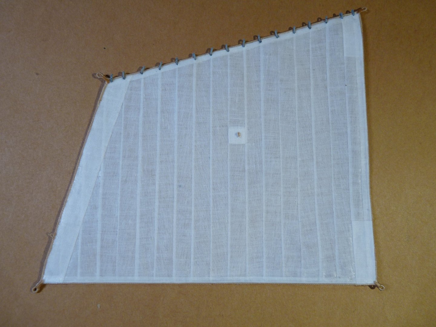
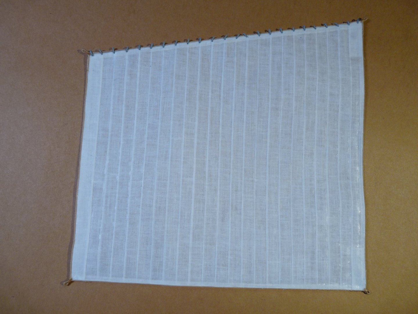
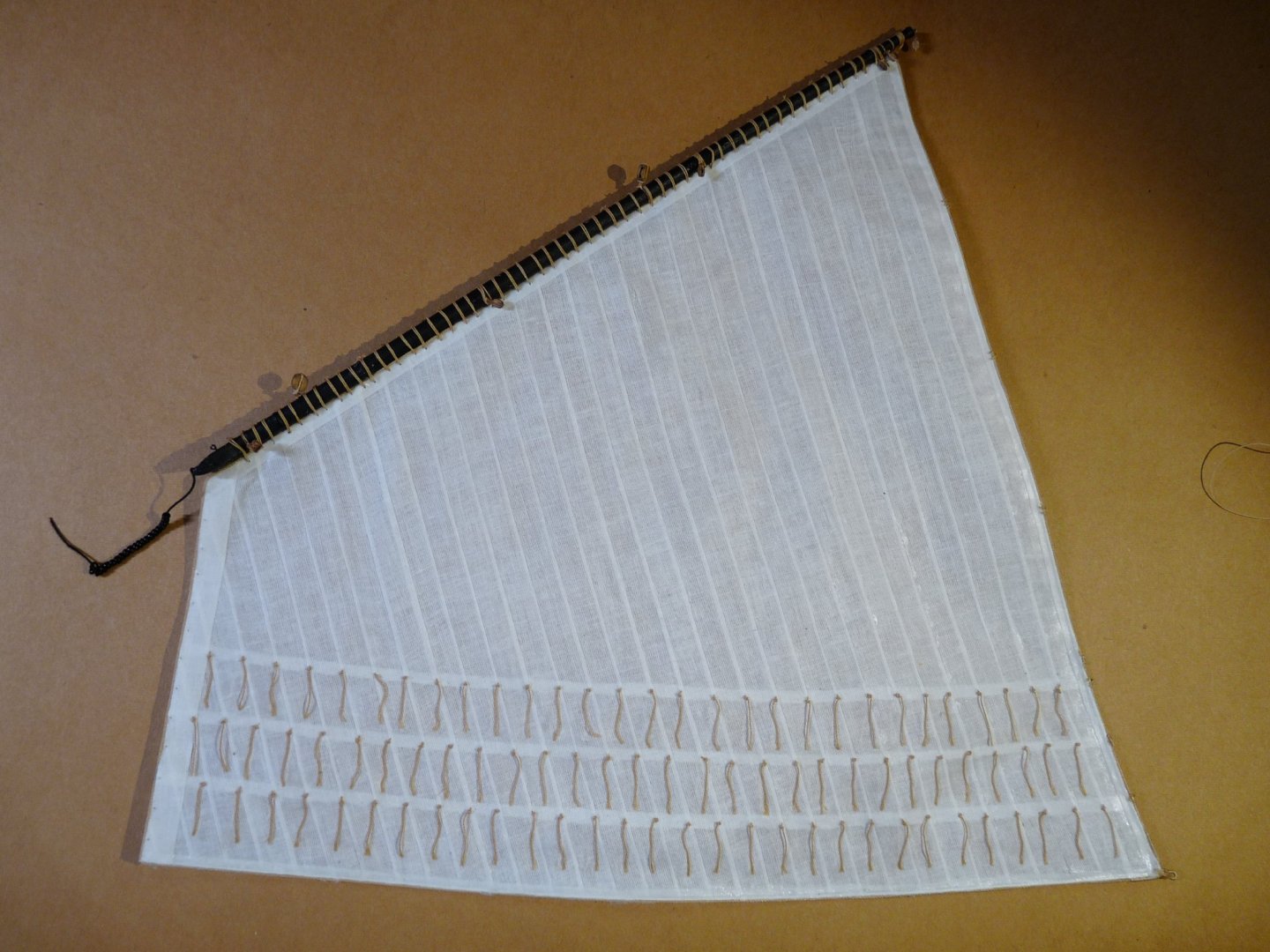
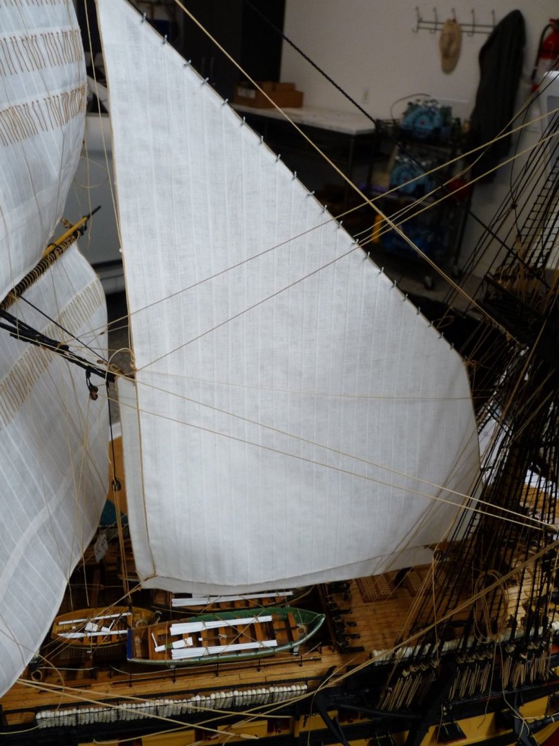
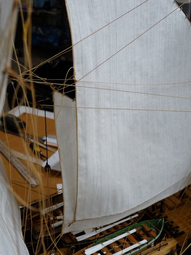
I have lately been working on making several new sails for Vic. Here are the results; ready to be mounted. Here is the mizzen topsail; prior to bending to the mizzen top yard: And, below, after bending to the yard: A close-up of the robands that lash the sail to the yard: The mizzen staysail: The middle staysail: And the driver (spanker), bent to the gaff:

-
I have gotten two more sails installed; the main staysail and the main topmast staysail. The addition of these two sails pretty much precluded access to belaying points around the foot of the fore mast as well as the general waist area, thus the need to pre-belay lines to be run to the fore topgallant area at a later date. This now completes the refurbishing of the sails that I had installed before and removed in July in order to install stiffening wires in their leeches and feet. Next, I'm on to the driver (spanker) and the mizzen topsail and a couple of the mizzen staysails. Then I'll be able to ship the three topgallant masts and their spars, and begin to complete the topgallant hamper of sails. I have had a few members inquire about my sails, if there is any interest I may post some pix and instructions on how I make them. Thanks for looking, Ted Insert.url


-
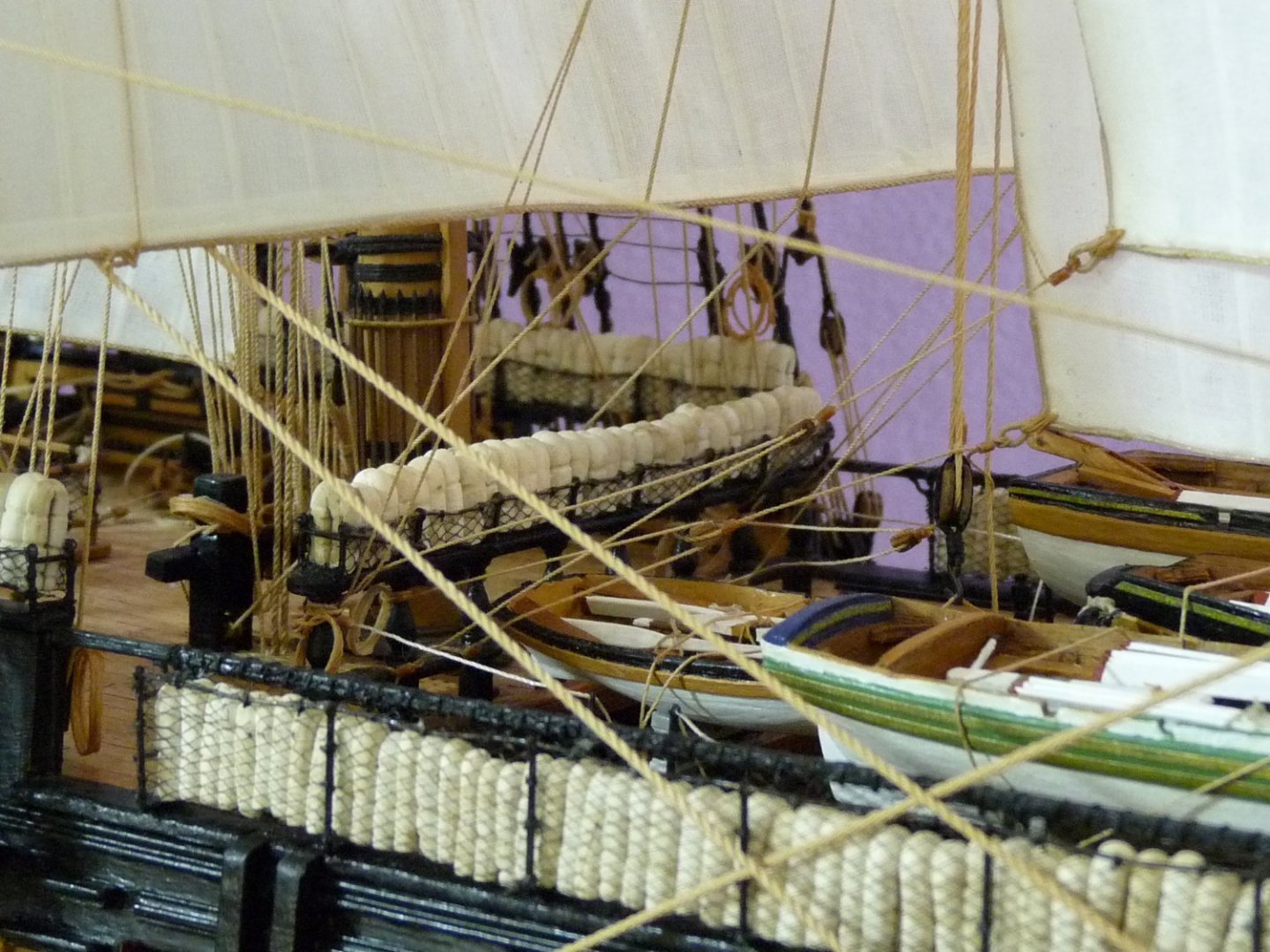
Sorry, I've been away for a while. Mort, thanks for the note regarding the Hammock netting. To be truthful, I don't remember where I got it for sure!. I think it was a piece of black tulle that I found in Joann's store. I made the nettings about 6 years ago, so the memory is a bit foggy! Malcolm, Thanks for the nice note. I was ambivalent about doing sails, but now that I have gotten better at it, I'm glad that I made the decision. Still have about a dozen to go!
-
Here is the latest update on repairing/replacing the sails on my HMS Victory. I have now hung the main course and topsails back on after refurbishing them with the stiffening wires. In these pix there are still many lines that need attaching, and the sails are not yet fully positioned nor adjusted. Next will be the replacement of the refurbished main stay sail and main topmast stay sails, Then I will be back to the point that I was in in July when I decided to remove the sails that I had hung, and fix them. You will note that the focs'l at the foot of the fore mast is a very congested area; lots of interference when trying to belay lines. To future avoid problems here after the addition of the main stay sails (which will make this area all but inaccessible), I have pre-belayed the running rigging for the fore topgallant sail and yard. These will be added at a later date.