drobinson02199
-
Posts
914 -
Joined
-
Last visited
Content Type
Profiles
Forums
Gallery
Events
Everything posted by drobinson02199
-
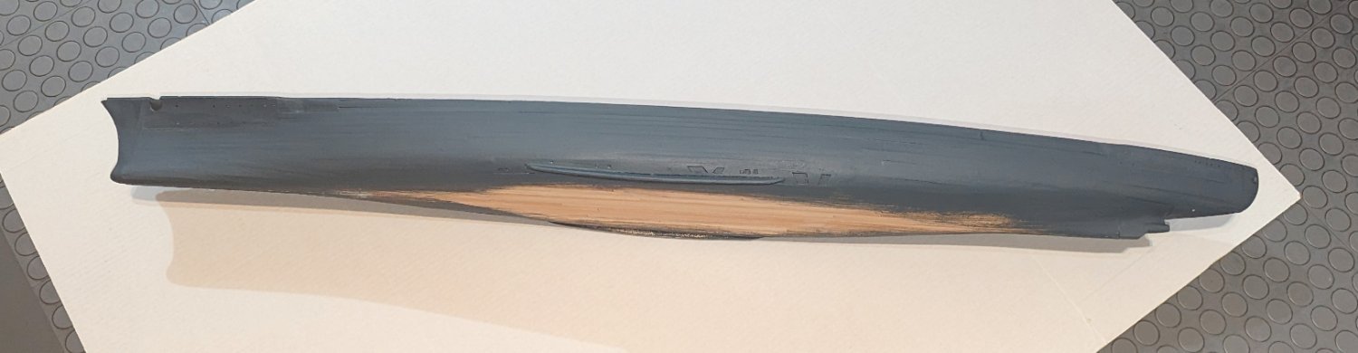
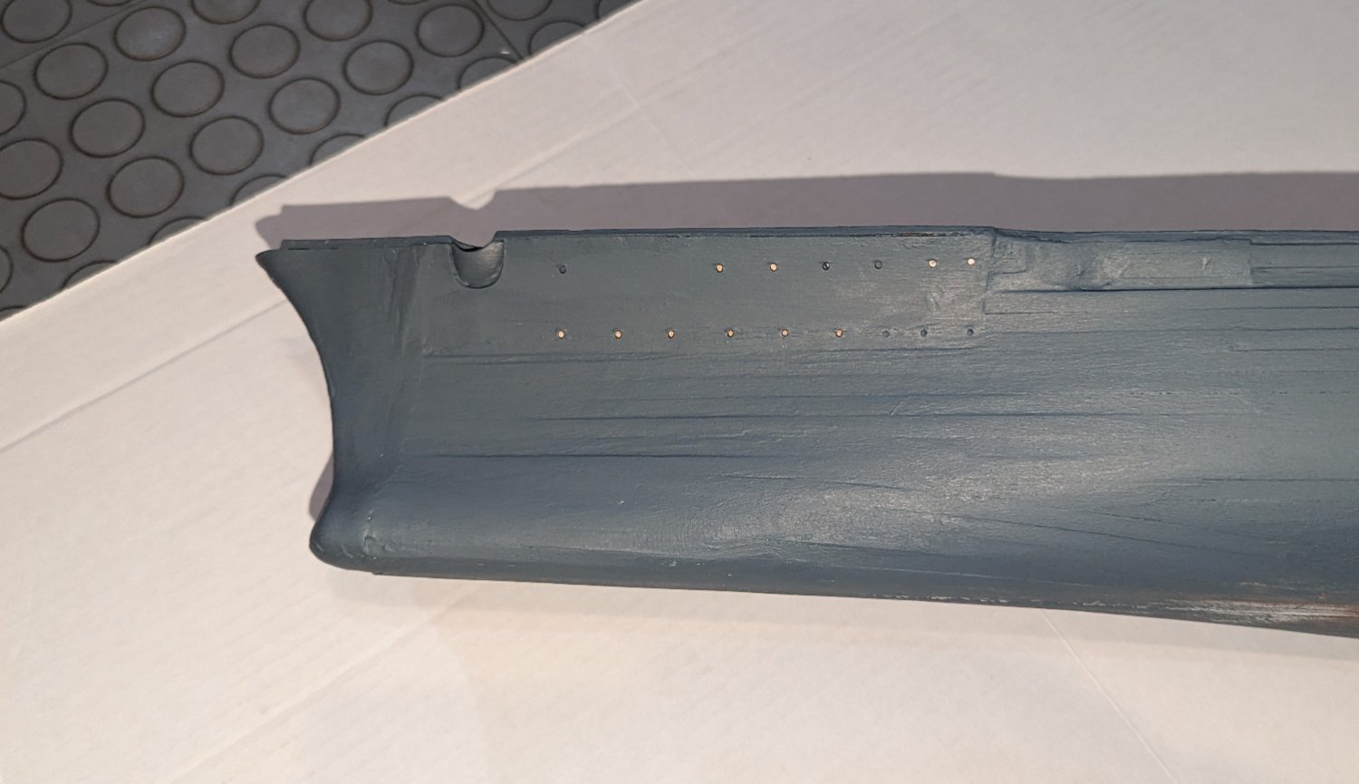
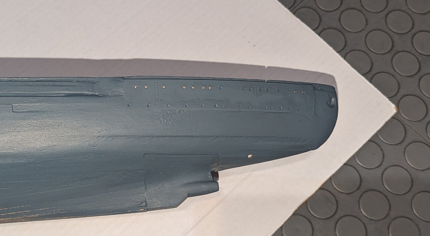
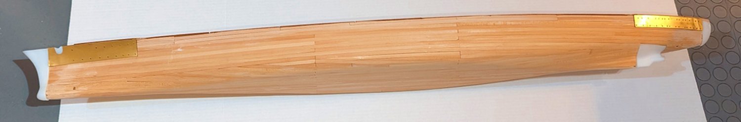
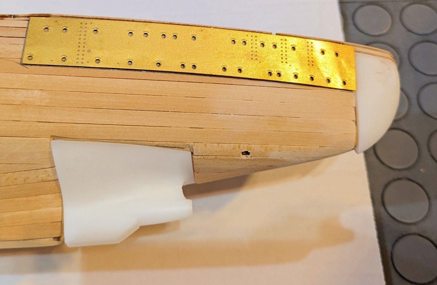
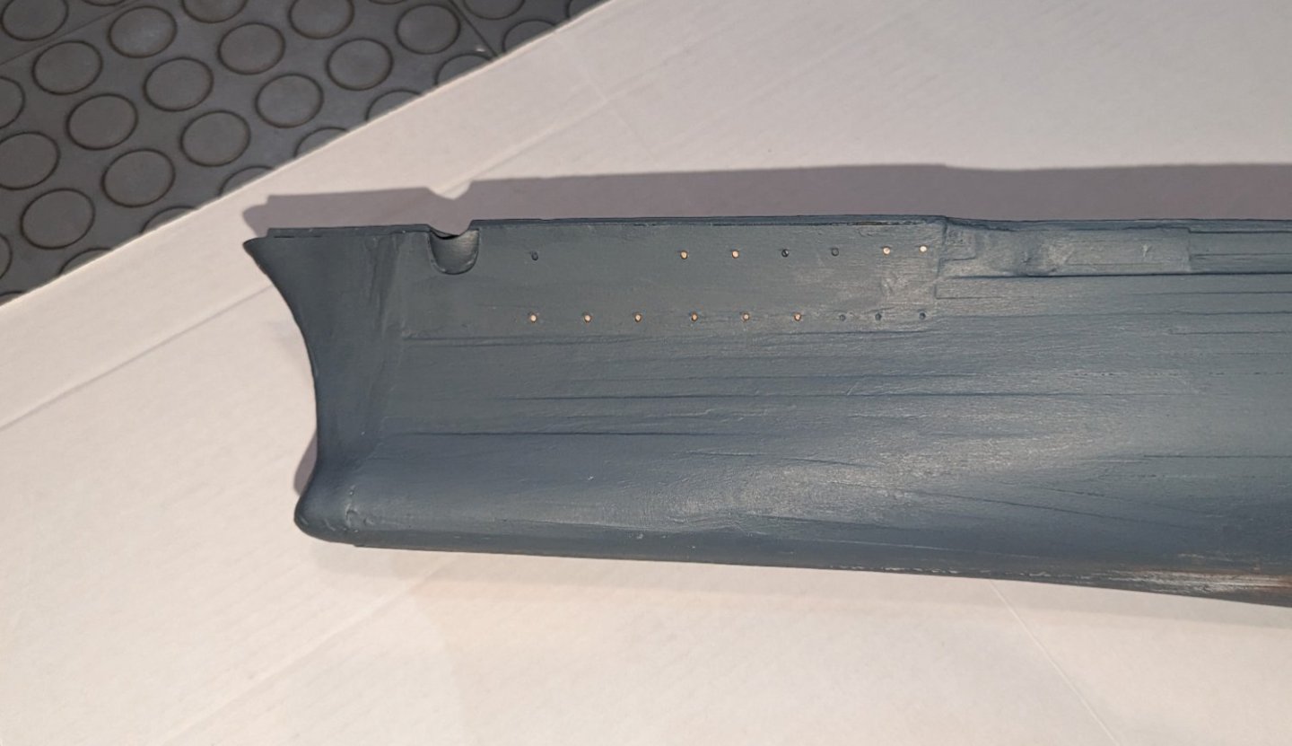
 What you see here represents about 5 coats of paint, and a bunch of follow-up puttying and sanding. I have a few comments about this hull structure: From a distance (full hull picture) it doesn't look too bad, especially in the lighting I'll have it shelved on (I tested that). You'll note that I didn't finish the bottom as that's going to be red-brown below the waterline. But up close, the brass plates at bow and stern are troublesome. Try as I might (and we have to acknowledge the limits of my woodworking skills) I couldn't get them to "disappear". Again, from a distance they don't look too bad. But if I had it to do all over again, I'd be tempted to skip the brass plates and second plank right over where they are, to give a uniform look, and then use the brass plates as templates to drill the portholes. I think I'll give bow and stern one more coat of paint, as that seems to help them "disappear". Regards, David

-
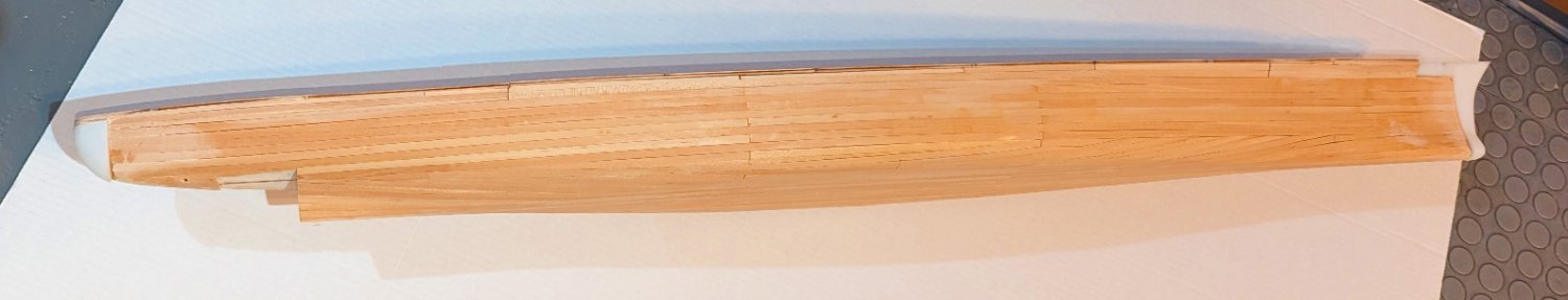
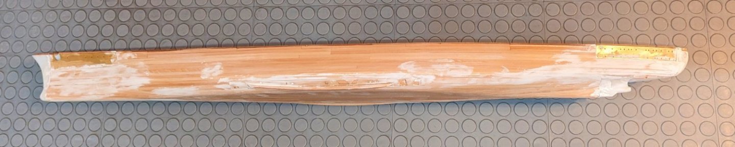
Second planking done; sealed with a coat of varnish, then putty applied. I took this against a gray background so you can see the putty. Now a first coat of paint, and we'll see where the imperfections really are. I'm going to brush coat this -- it's too big for my spray booth, and it's too cold outside spray it in the garage. Regards, David
-
Now in the middle of second planking. As the hull curves from side to bottom, there is a piece that needs to be installed. It comes off the laser sheet flat, and has to adapt to the curve of the hull. I used my steamer, and a bunch of CA glue and accelerator. The wider side pieces are fairly easy to shape -- but the narrower center is a bear. Regards, David


-
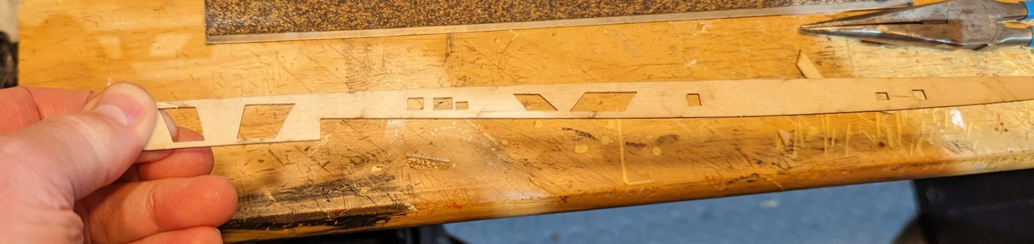
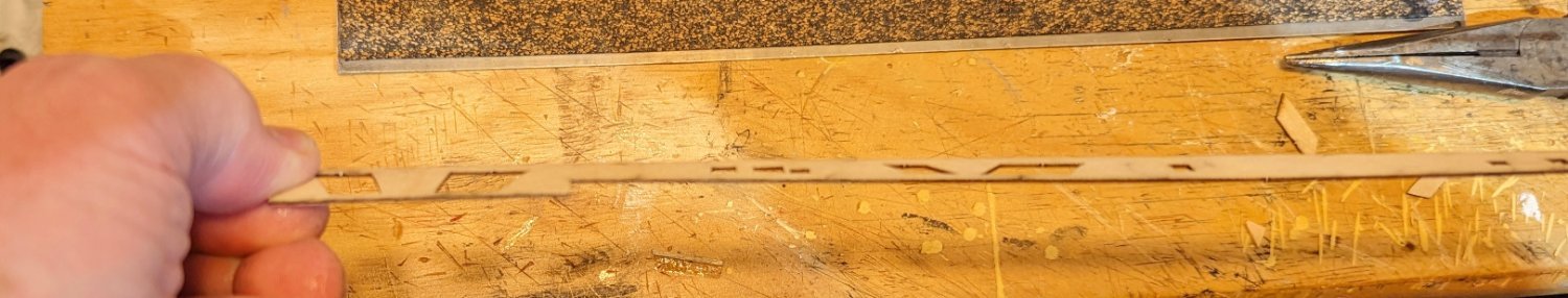
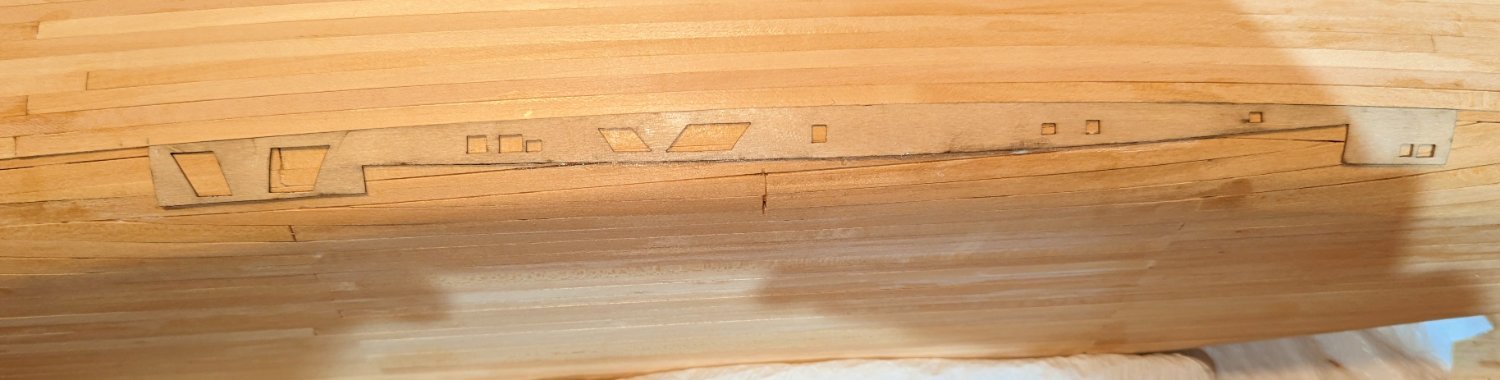
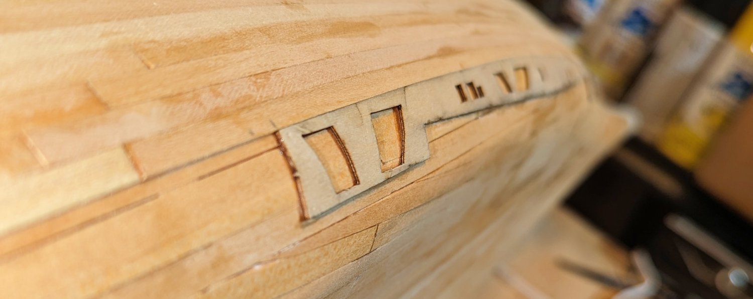
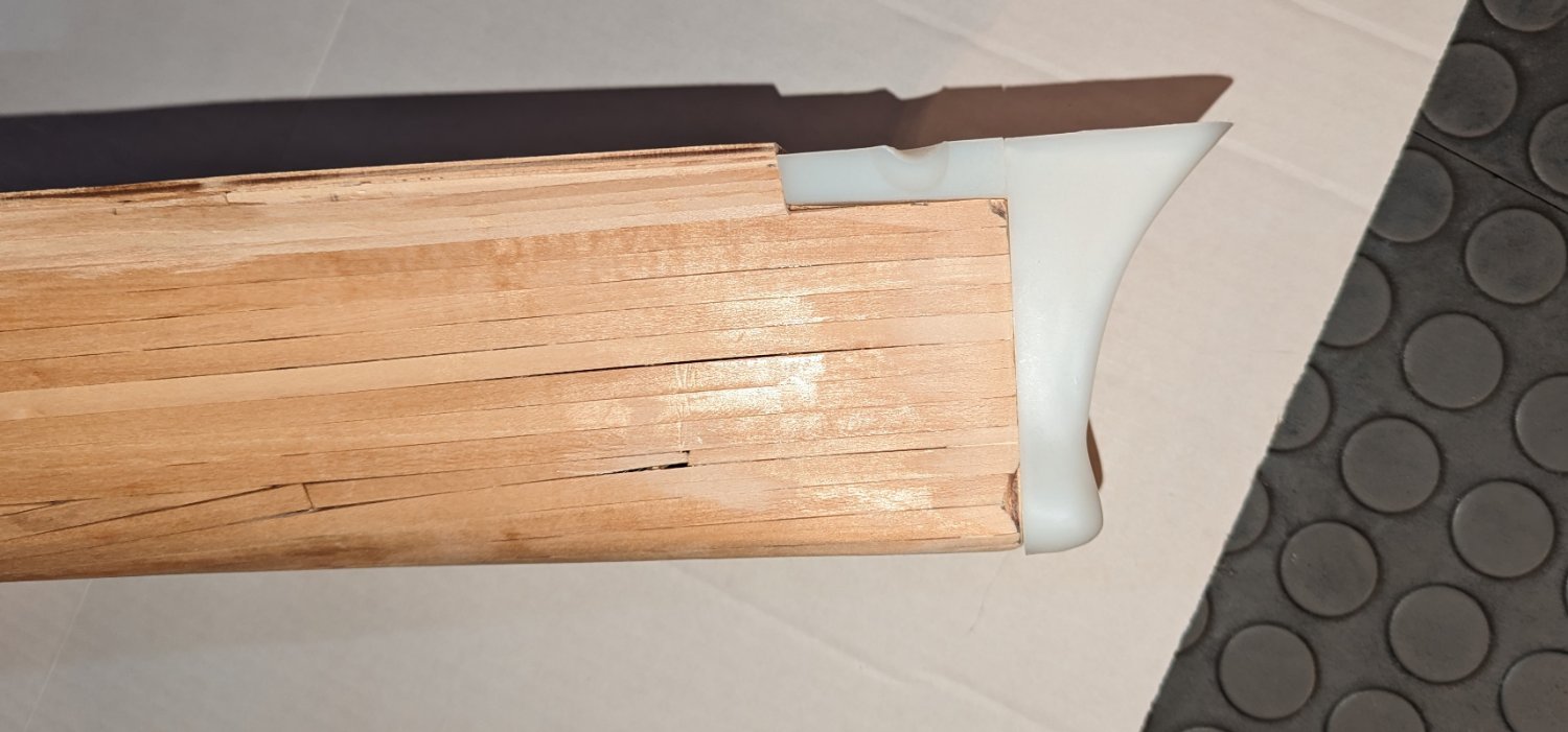
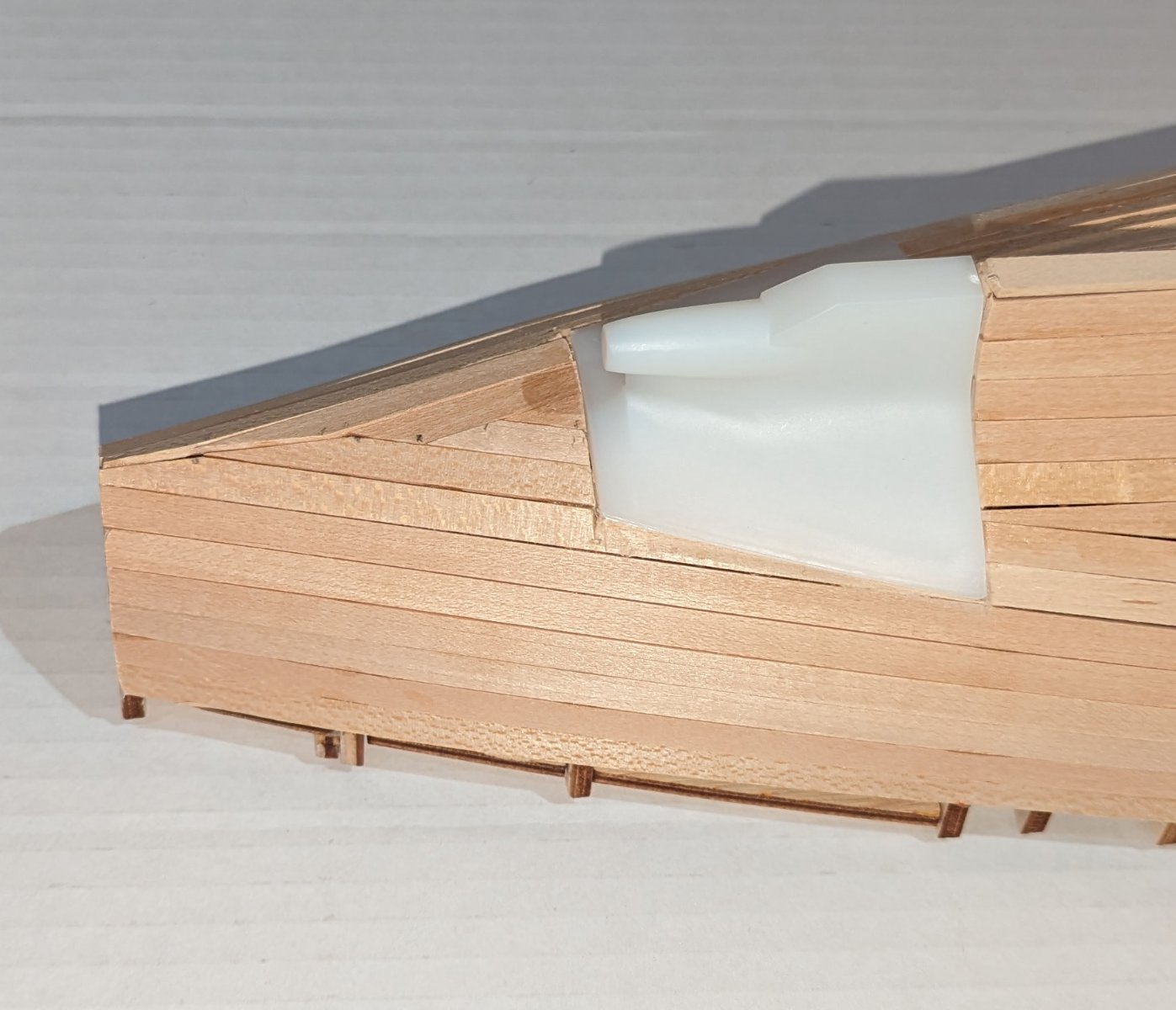
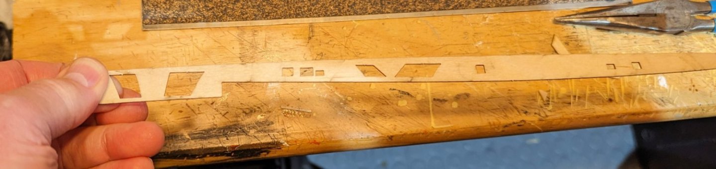
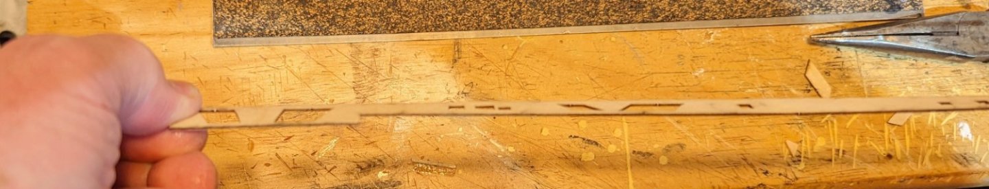
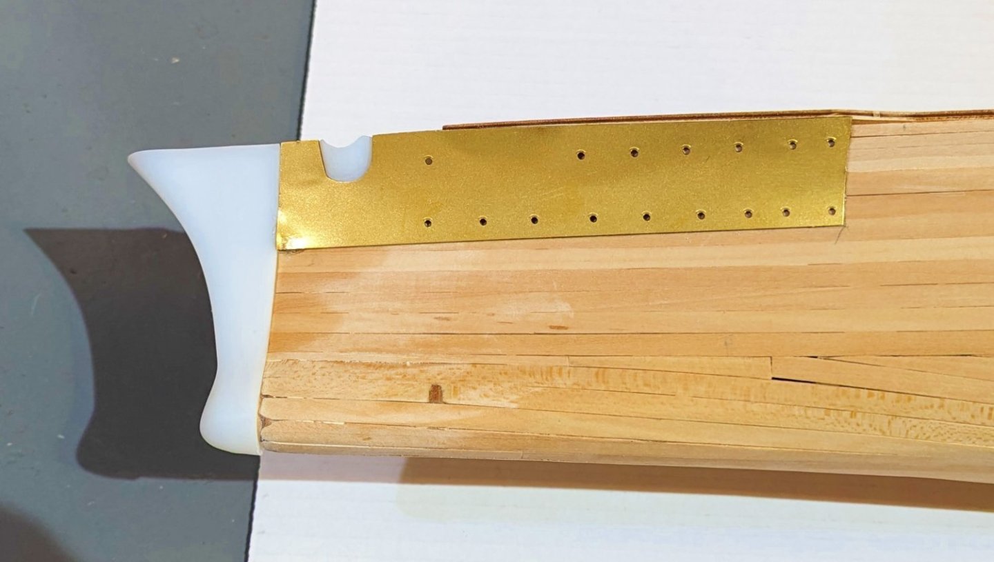
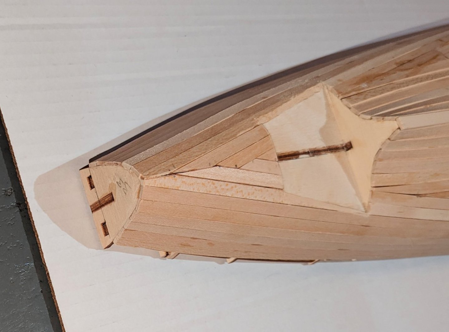
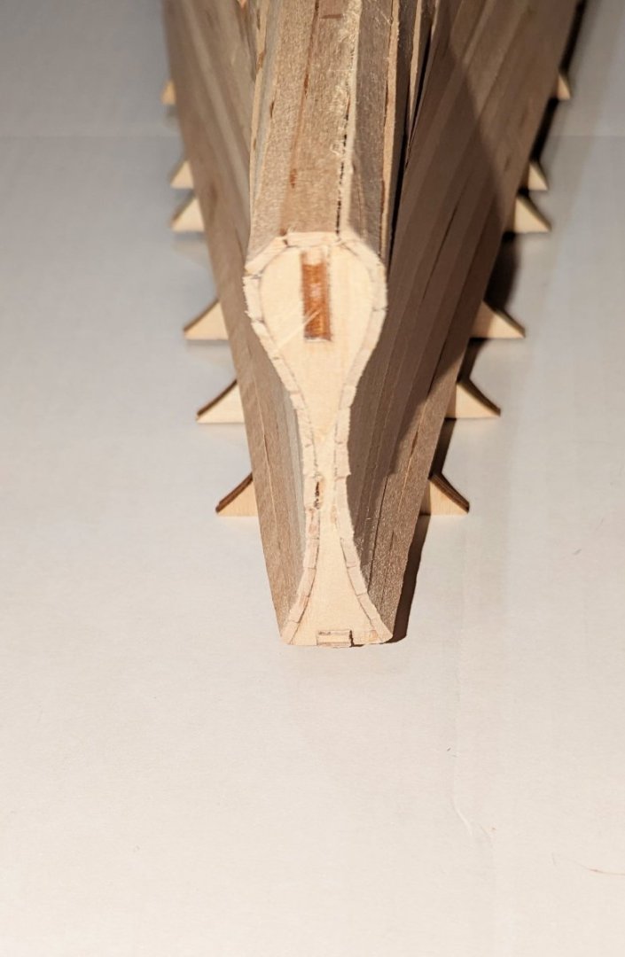
The model uses brass bulwarks at the bow and stern -- I think probably to define the portholes cleanly. There's also a resin piece added in these pics on the lower stern. Next step is second planking. Regards, David


-
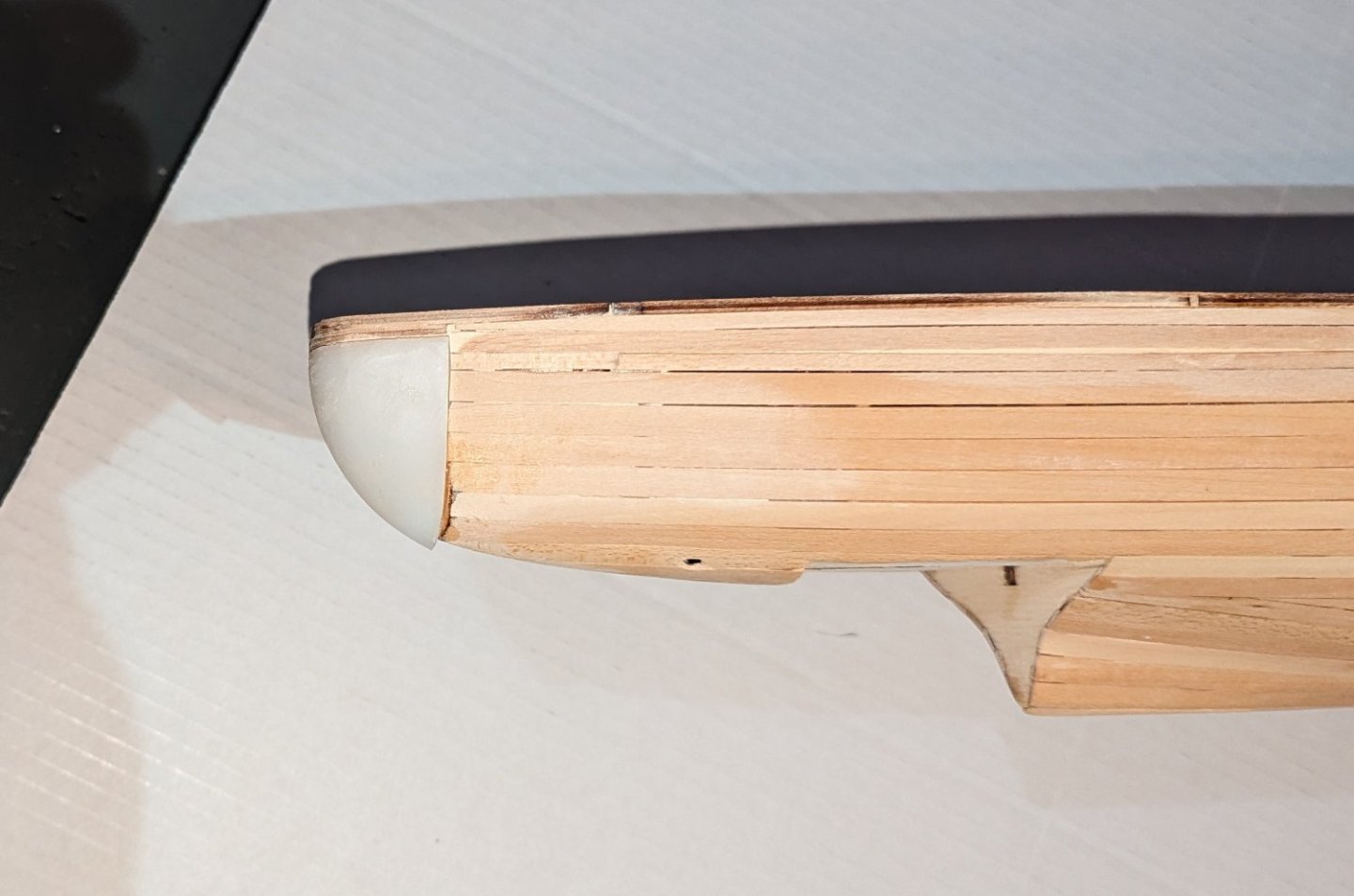
The hull is closed completely, and some of the resin pieces are now mounted on the bow and stern. Takes a lot of sanding and fitting to get the resin pieces right. Regards, David


-
The removable decks are now permanently glued down, and I'm beginning to close the hull in the unplanked spaces. Here's the bow section closed. Next is a similar section at the stern. Then the center of the ship. Regards, David

-
Decks now have cladding. Pictures show the removable decks installed and also removed. Later on, pre-formed deck sections with fine deck planking already "printed" on will be applied. Regards, David

-
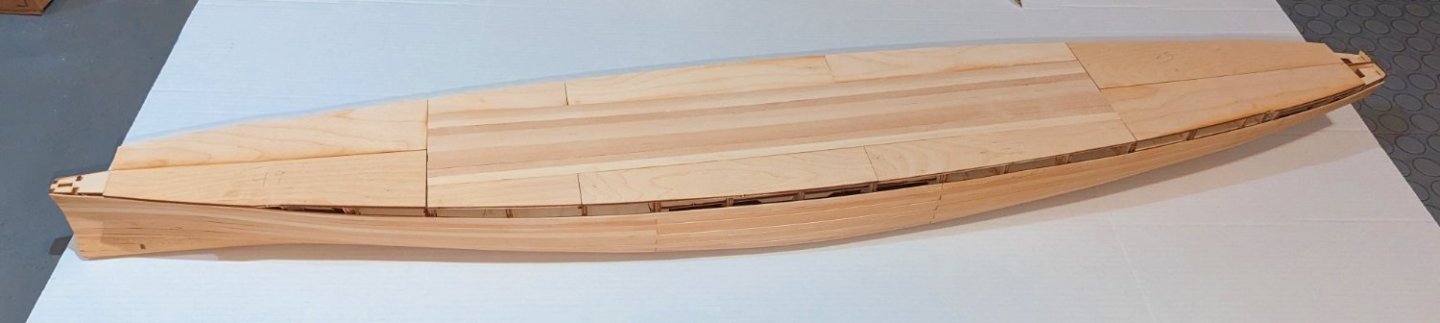
First planking now sanded and varnished. Regards, David
-
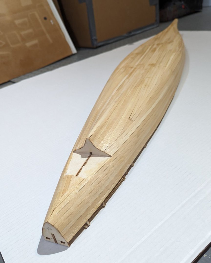
First planking done. These are pictures of the rough, unsanded hull. There is a plastic piece that fits into the hull as shown. Regards, David

-
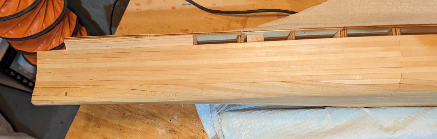
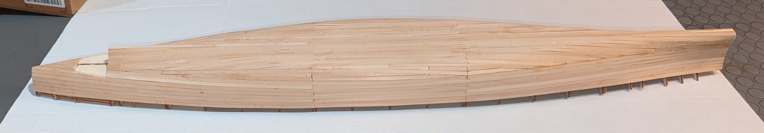
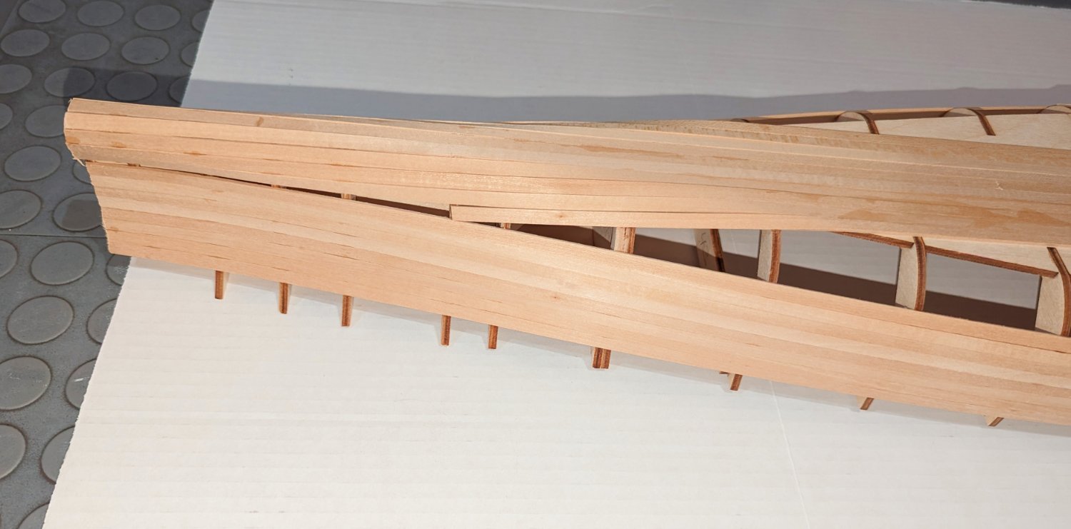
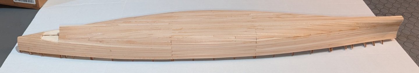
Planking progressing. I'm now at the point where I need to start shaping planks and using stealers. The planking wraps around the hull at the bow and stern, and I've used my steamer to help smooth that. This hull shape so far has not had much if any twisting of planks. The last picture has sort of an optical illusion, so I added an arrowhead. The face it's pointing to is vertical and faces aft toward the stern. But if you look for a bit it will "flip." Regards, David

-
First planking started -- four planks laid. Regards, David


-
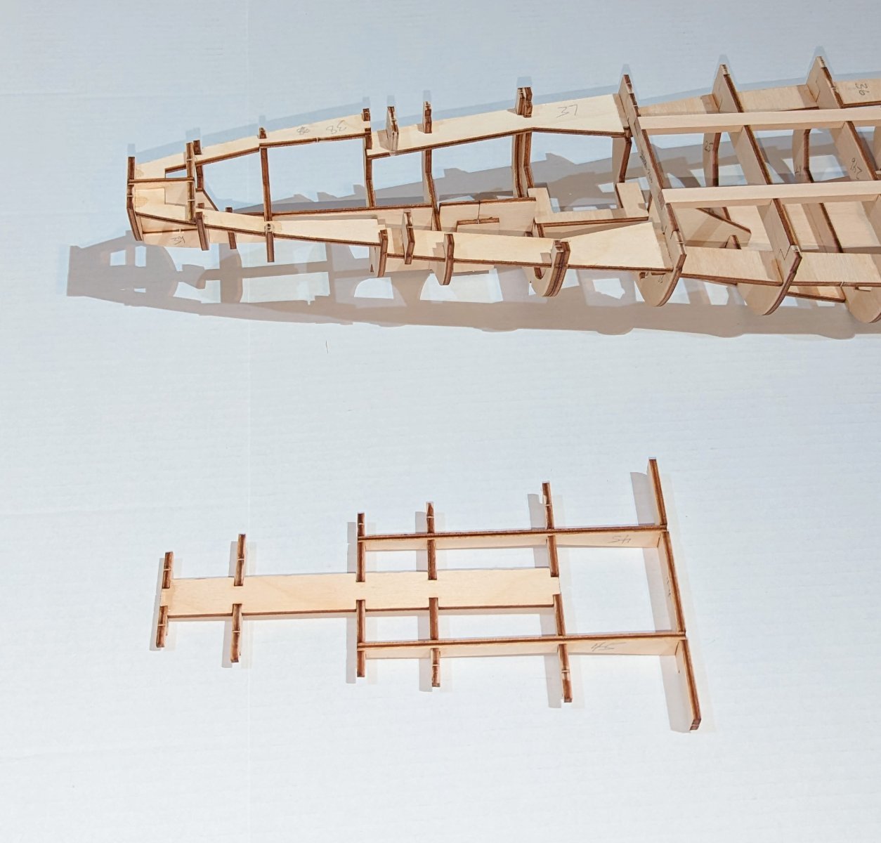
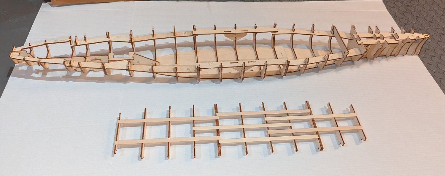
A smaller bow deck is also removable. Regards, David

-
The deck is built to be removable, in anticipation of R/C requirements. Since this will be a static model, at some point it will be glued down. Regards, David

-
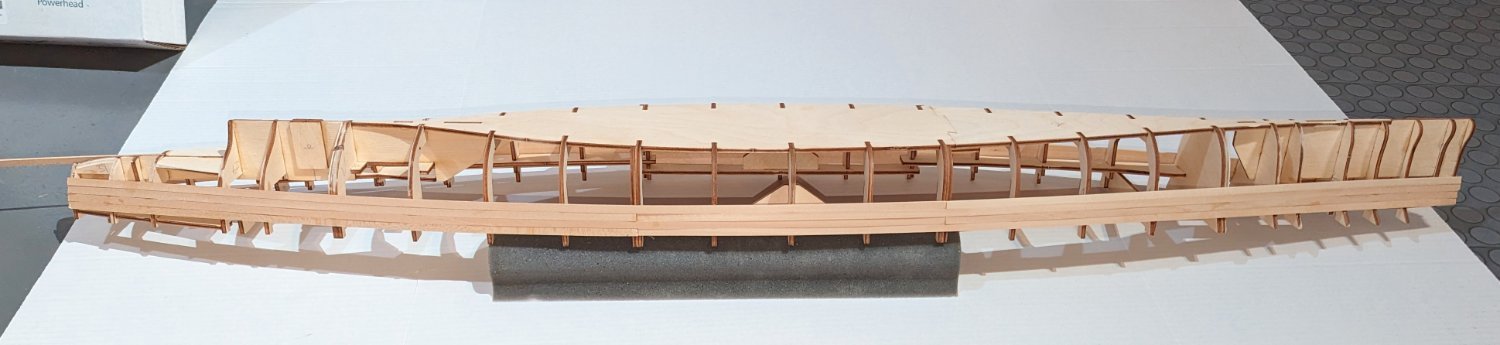
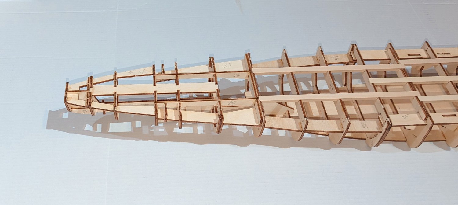
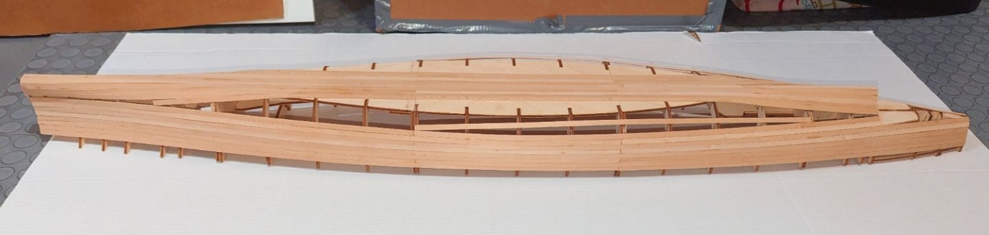
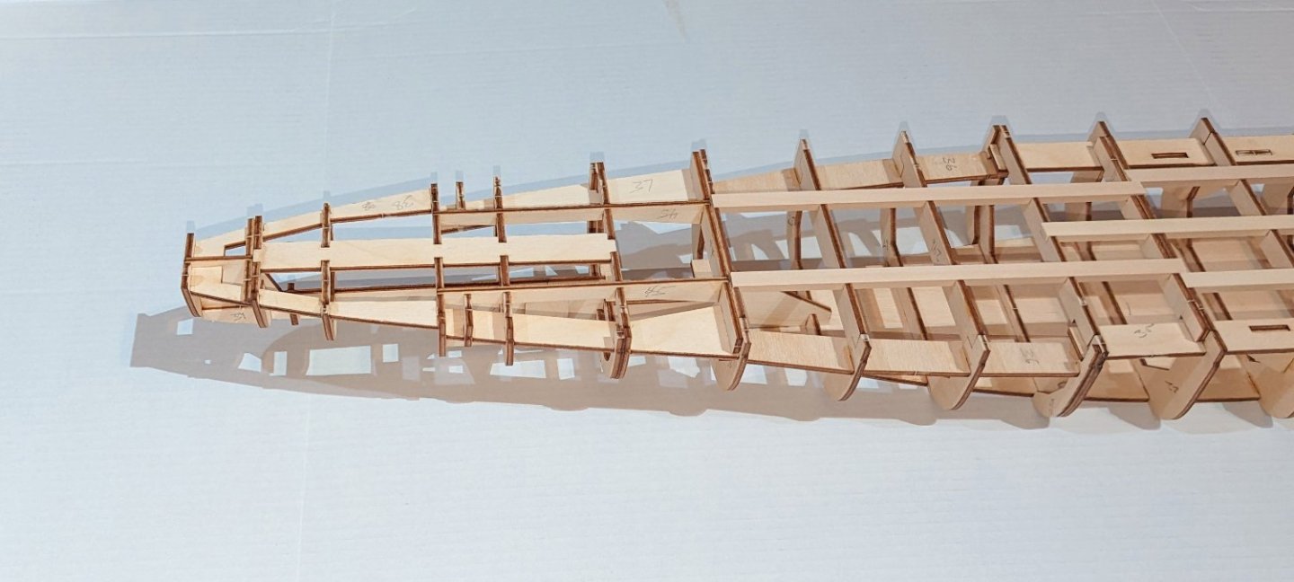
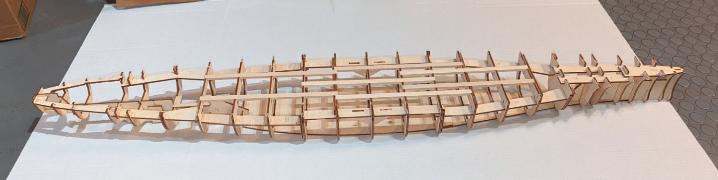
Here's the hull with a bunch of horizontal reinforcing structures added. This eases my mind, because those frame ribs are really "twangy" and not very strong on their own, and a stray elbow would have broken one. Regards, David

-
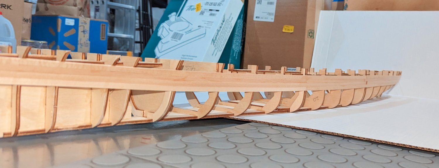
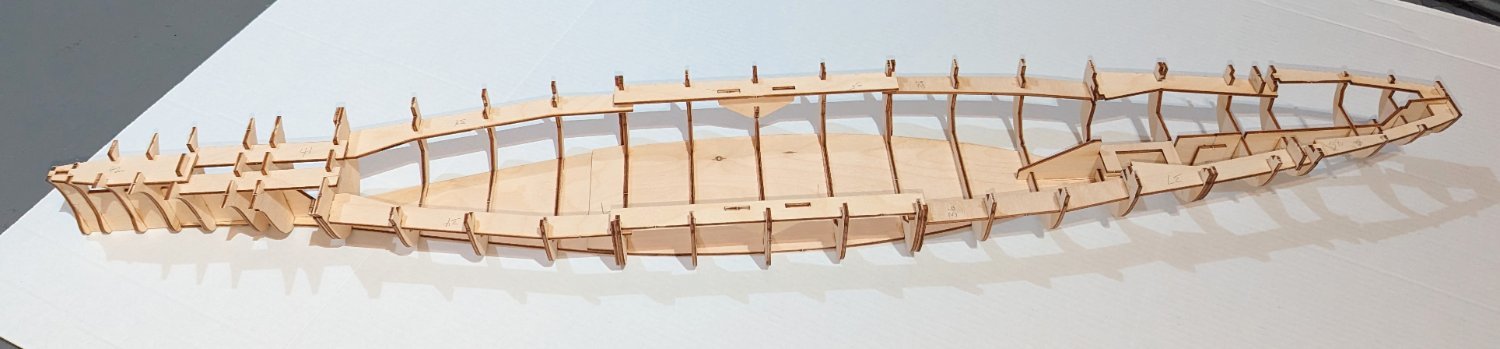
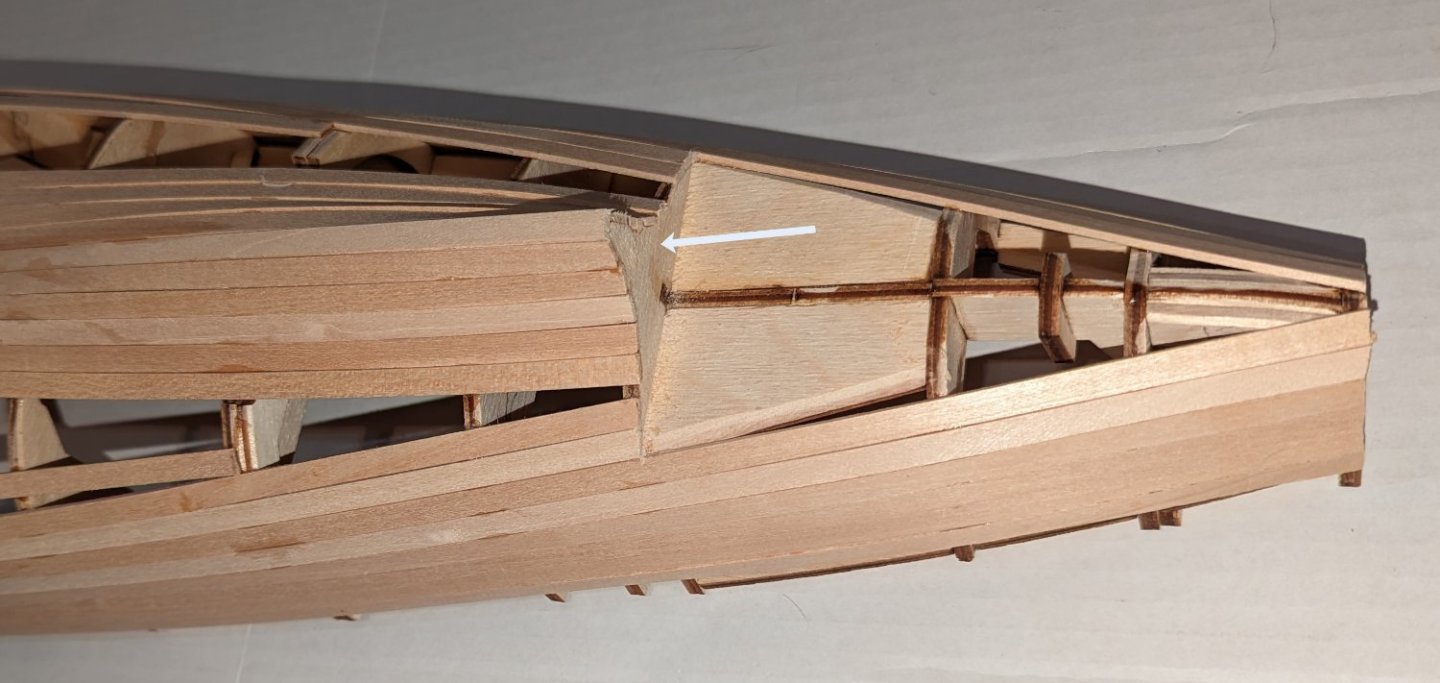
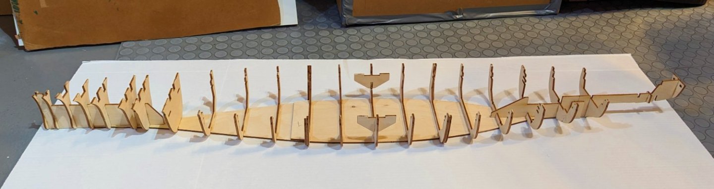
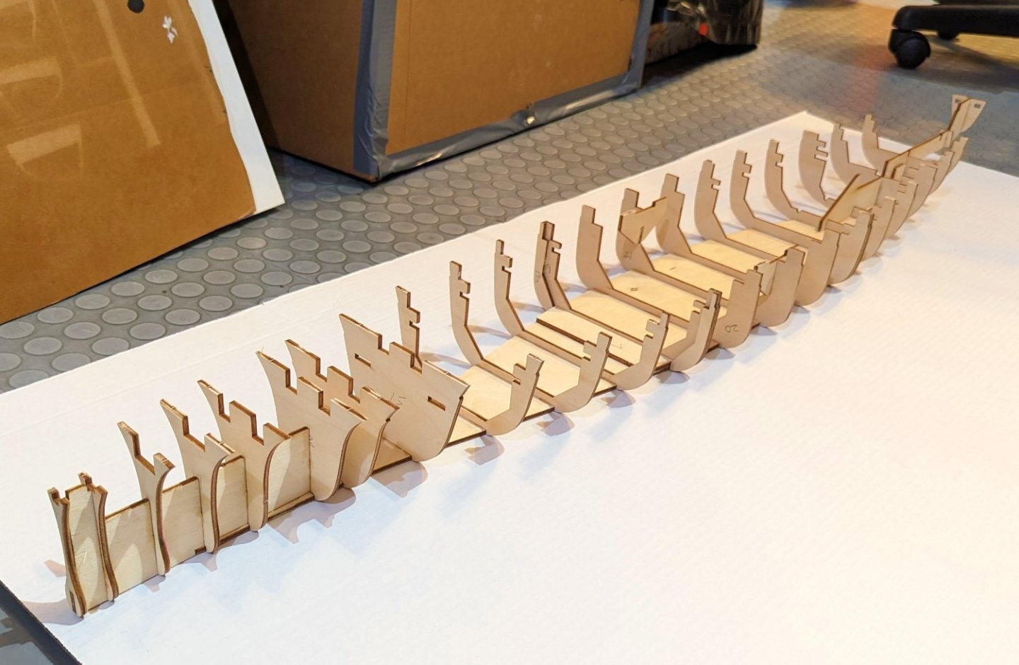
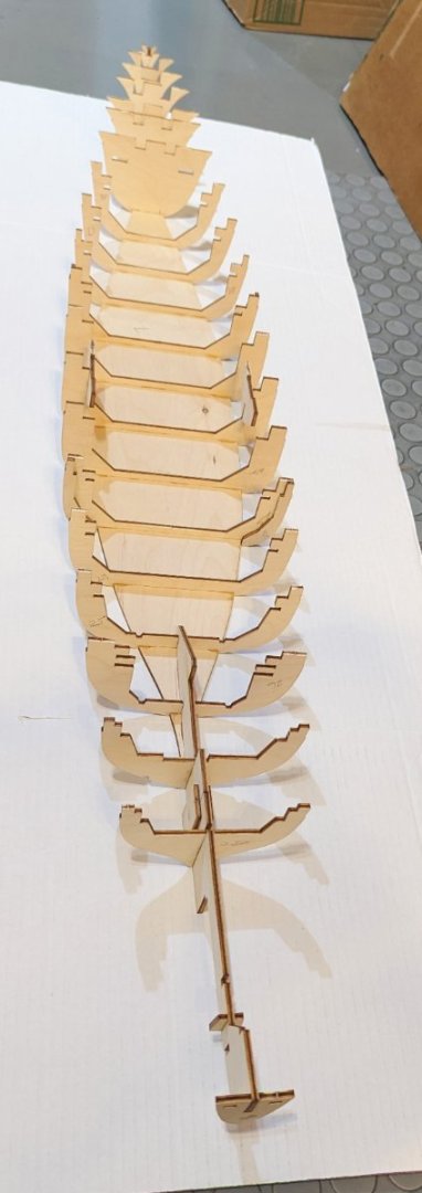
Here's the first part of the keel and frame structure. This will be the longest model in my collection -- what you see here weighs in at 48" long. Hats off to Amati for the plywood laser cutting. Very few connection points to cut, and they are tiny and easily cut. The frames fit into slots with no sanding required -- in fact, there is enough play in them that I used a square while gluing to keep them aligned. Manual called for wood glue, which would have taken forever given drying time. I used BSI medium gel, which is my go-to glue for everything. Regards, David
-
Thomas -- I got it from Ages of Sail, which is where I buy many of my European kits. I think they are the Amati distributor for the US. Regards, David
-
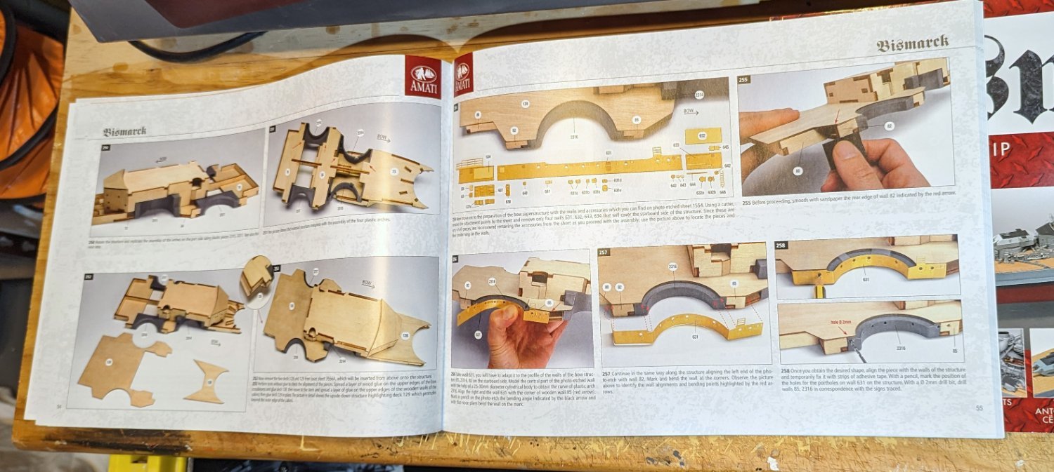
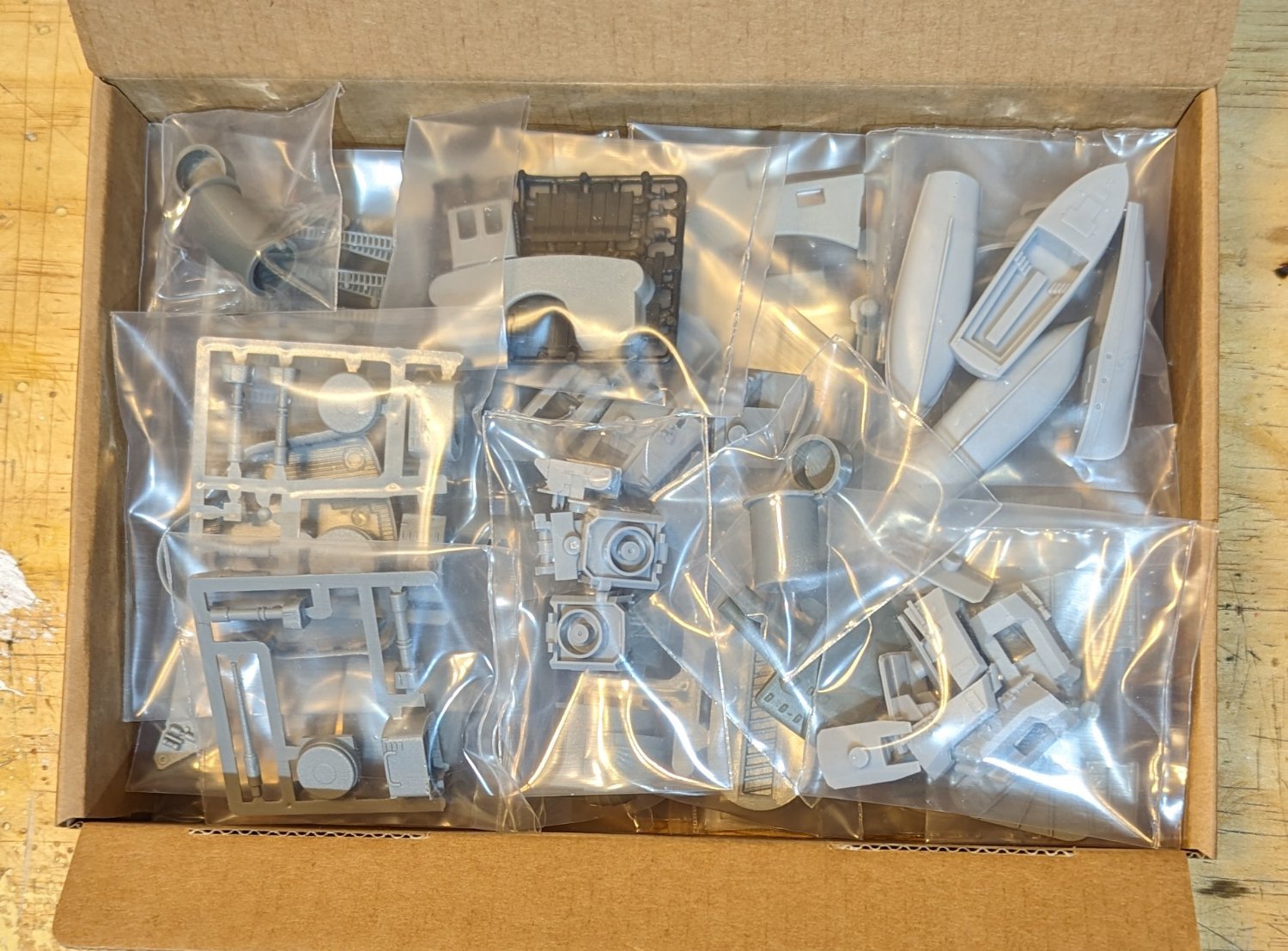
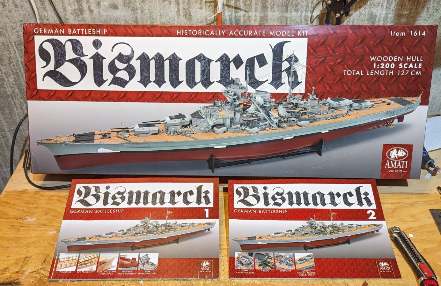
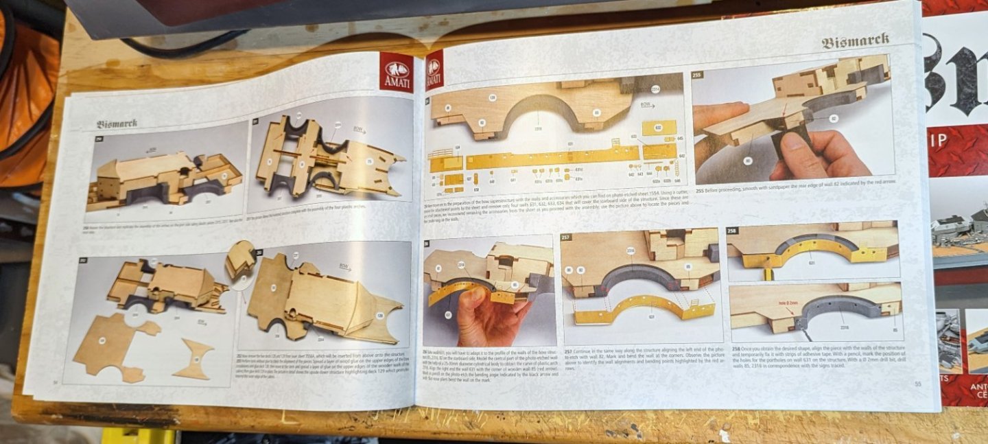
Time to tackle the Bismarck. I'll start with a version of the traditional "what's in the box?" You can see the finished model on the box as well as two very detailed instruction books with color pictures. Example of detail page shown. The hull and deck are wood, but much of the superstructure is built from plastic parts -- I've shown a sample of how they are packaged (in individual clear plastic envelopes). There probably isn't another material that would be feasible. The box says that there are "2,266 photoetched parts" -- so this will take a while. I don't know if that count includes the plastic parts and it's just sloppy box legend drafting, but there are a lot of plastic parts. The usual things are in the kit: wood strip, photo-etched brass, and laser-cut sheets. Those, interestingly, appear to be made of plywood (I haven't pulled any out of the box yet). That's a shift from other Amati models in the Victory series that I have built that used MDF for the hull and frames. This will also be the longest model I have built at 132 cm. Regards, David

-
Thanks, Bob. I've really enjoyed your "USCG Insider" comments. Next one up, when I get motivated, will be the Amati Bismarck. Regards, David
- 46 replies
-
- 6
-

-
- Fast Response Cutter
- Dumas
- (and 2 more)
-
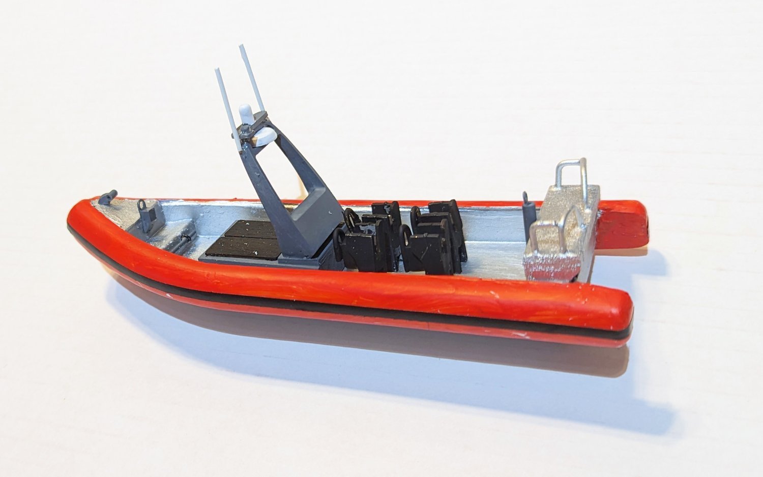
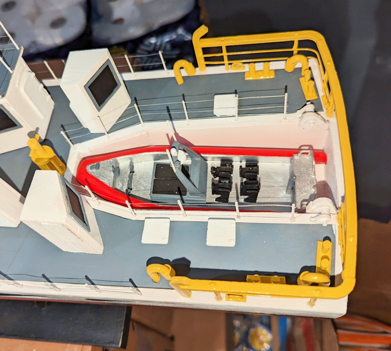
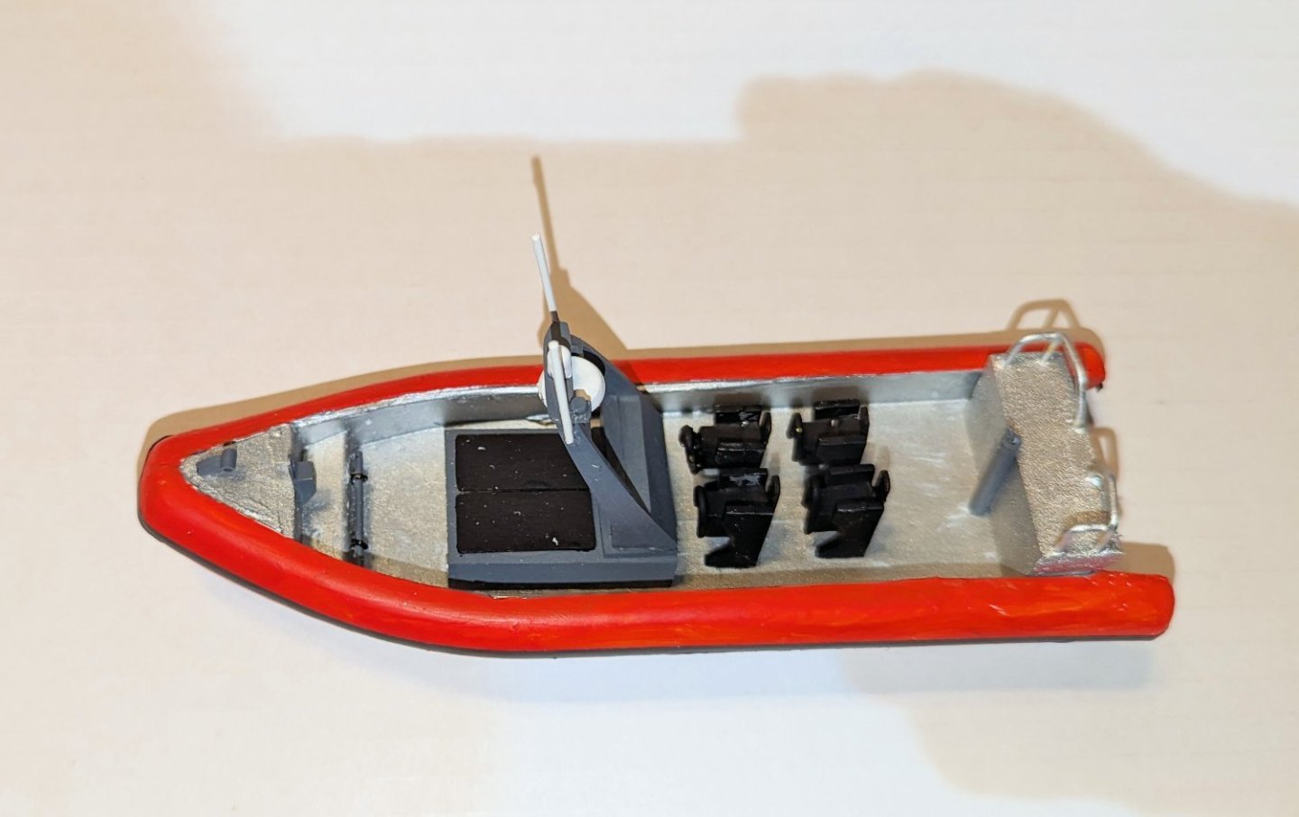
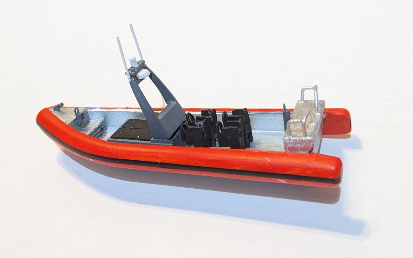
Completed! Last step was to build the little Naiad boat that goes into the rear launch well. Some pics here of that. A full set of completion photos is in the Completed Kit Built Gallery. Regards, David

- 46 replies
-
- 11
-
-

-
- Fast Response Cutter
- Dumas
- (and 2 more)
-
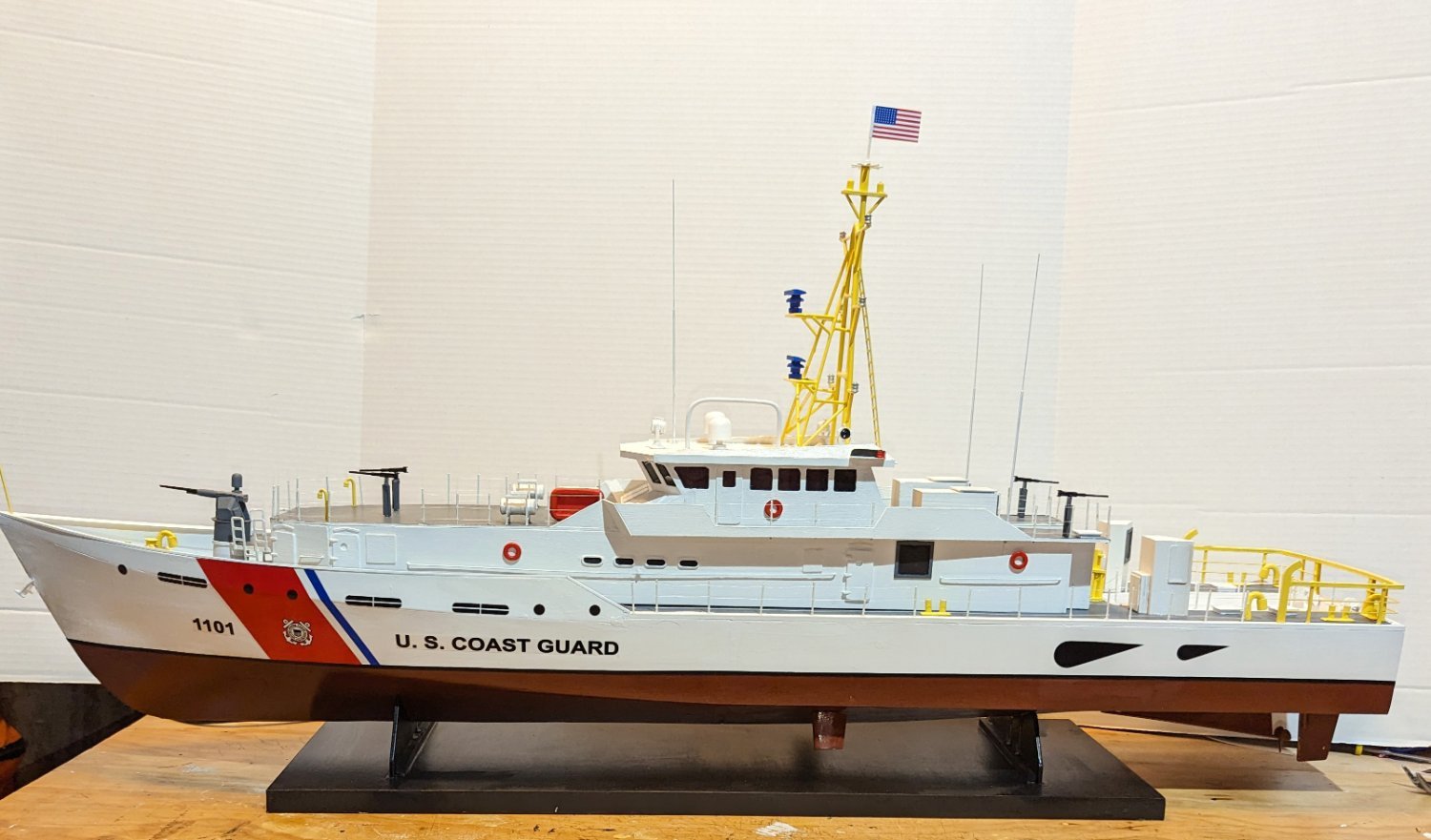
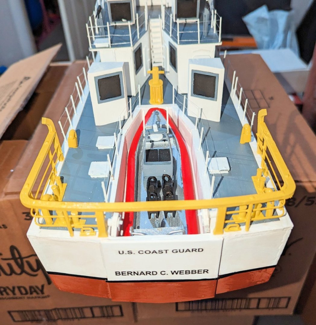
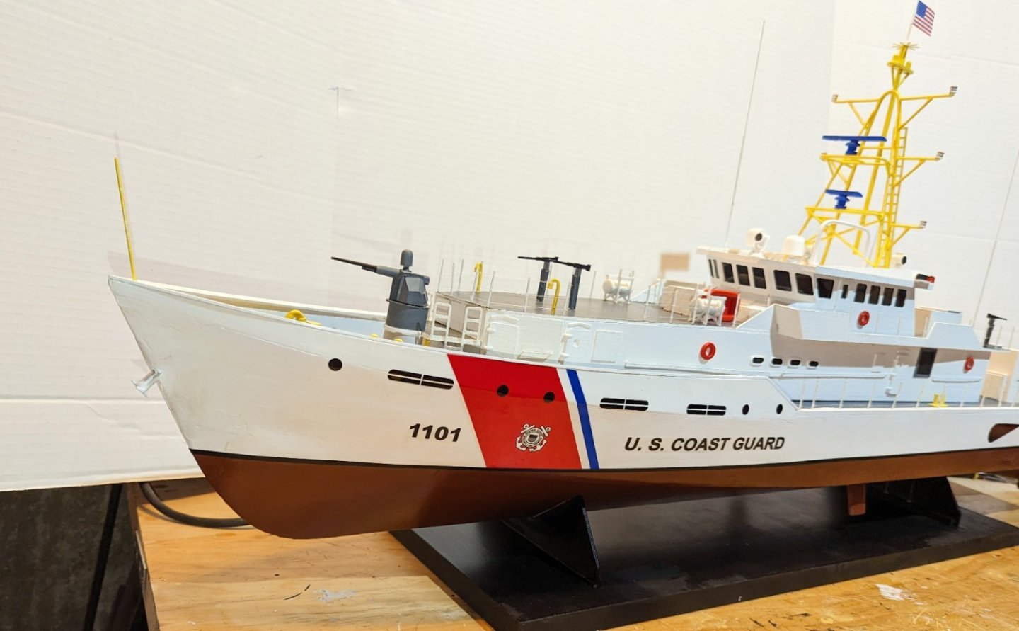
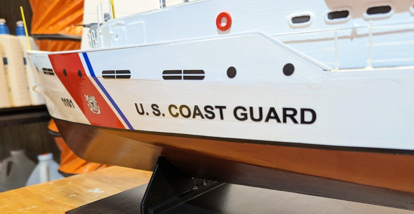
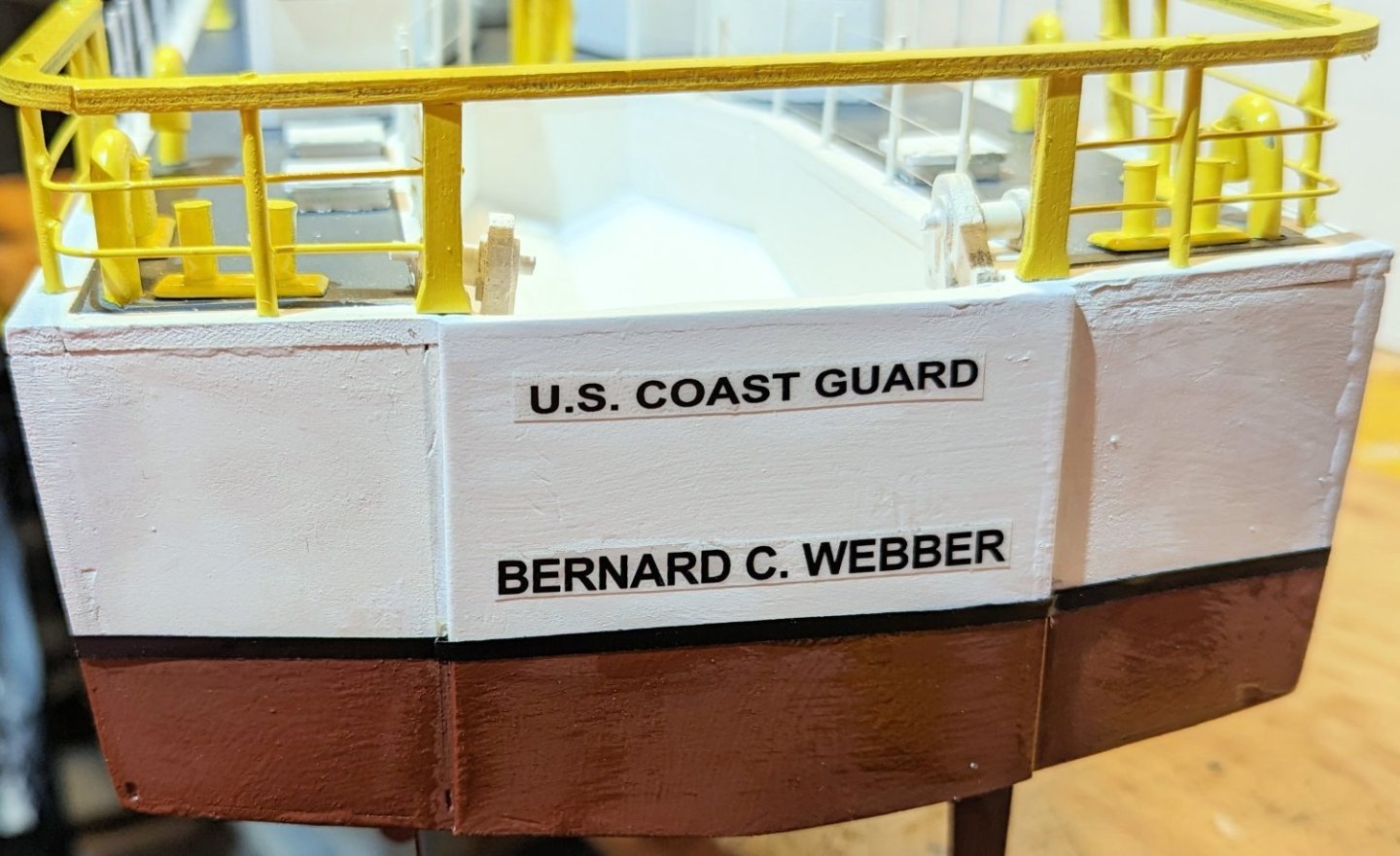
Lots more done. Finished the railings on the main deck and cabin deck. Applied all of the decals, which really spiffs up the ship Applied black striping at the waterline. Now what remains is the little Zodiac boat that fits into the rear well -- and that will be it. Regards, David

- 46 replies
-
- 9
-
-
-
- Fast Response Cutter
- Dumas
- (and 2 more)
-
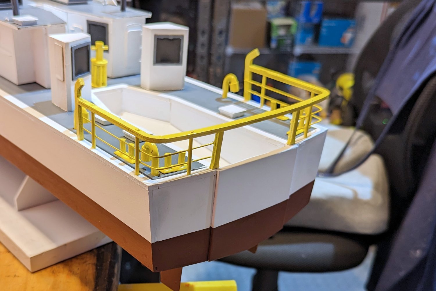
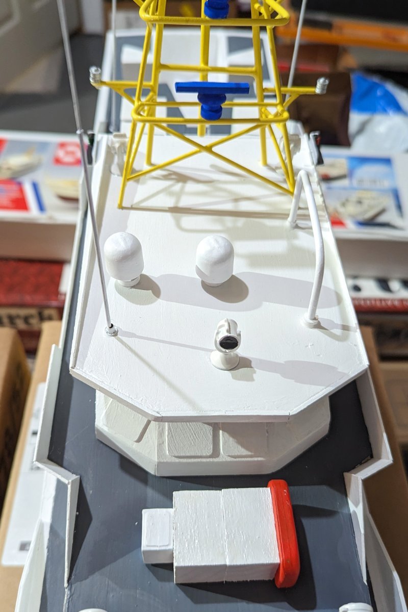
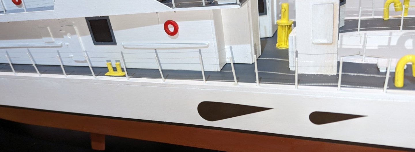
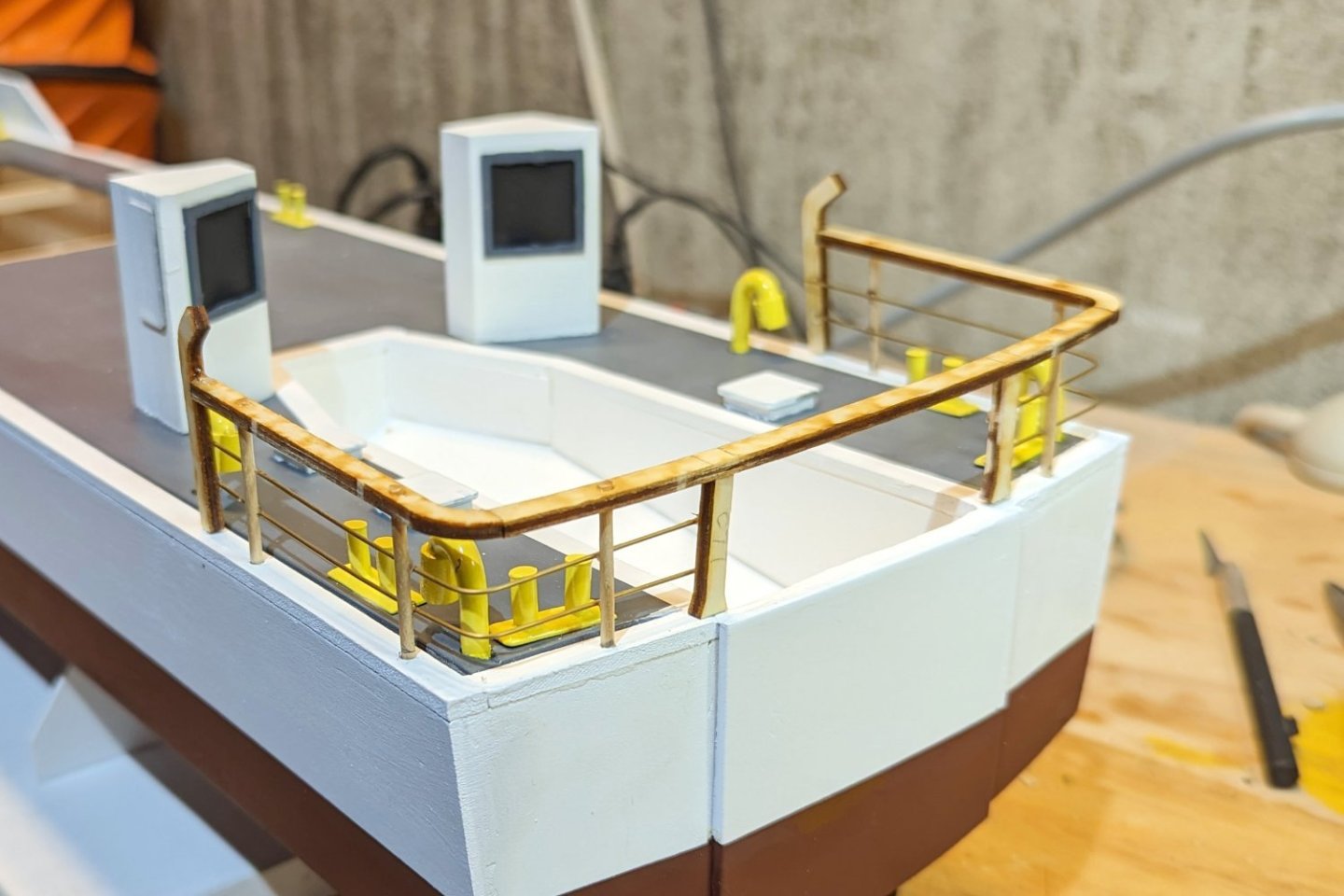
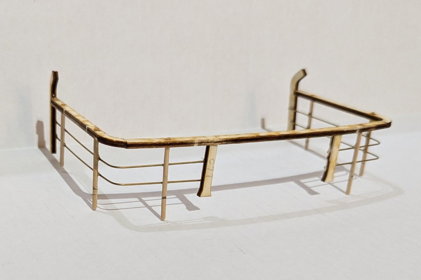
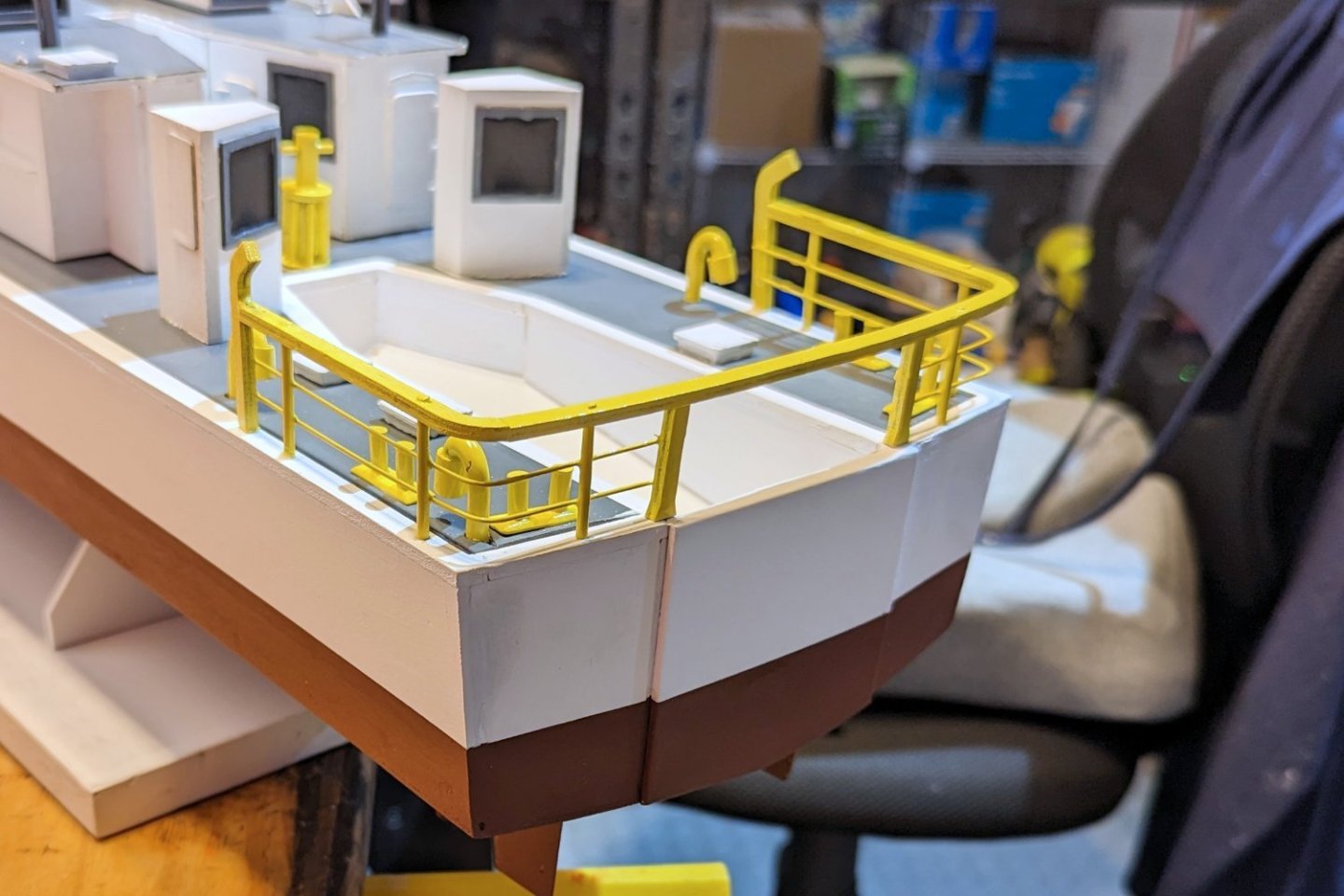
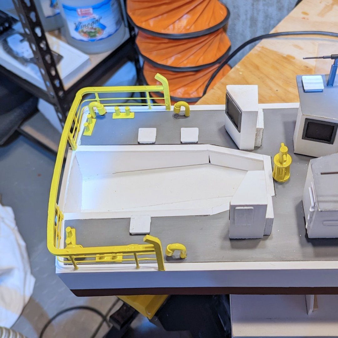
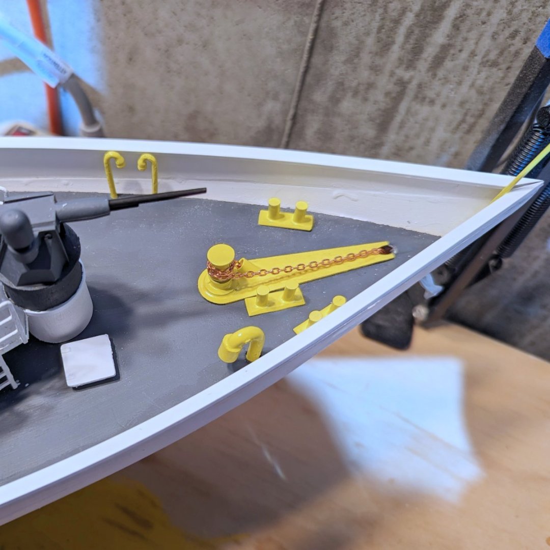
More deck fittings. The instruction manual says to build the rear railing fixed onto the stern, and then paint it. But my only yellow is spray paint, which I want to match to, so I reverse engineered it to make it removable. See first two pictures. Then painted yellow. Other deck fittings on stern and bow shown below. Regards, David
- 46 replies
-
- 7
-
-
- Fast Response Cutter
- Dumas
- (and 2 more)
-
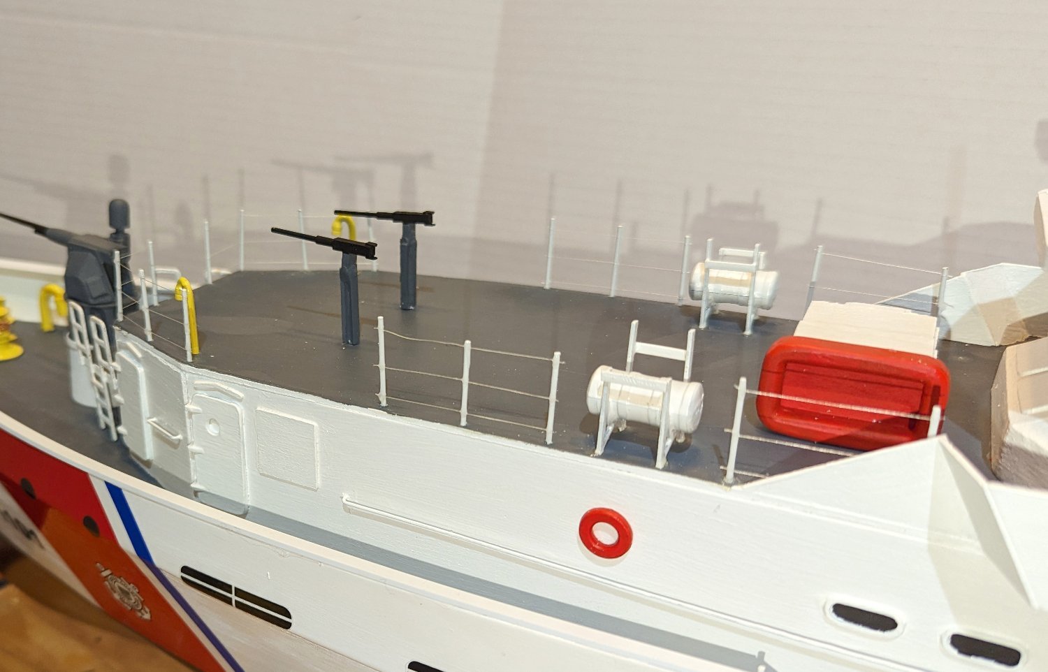
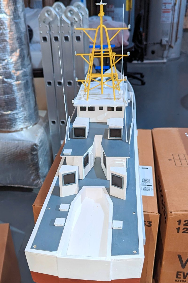
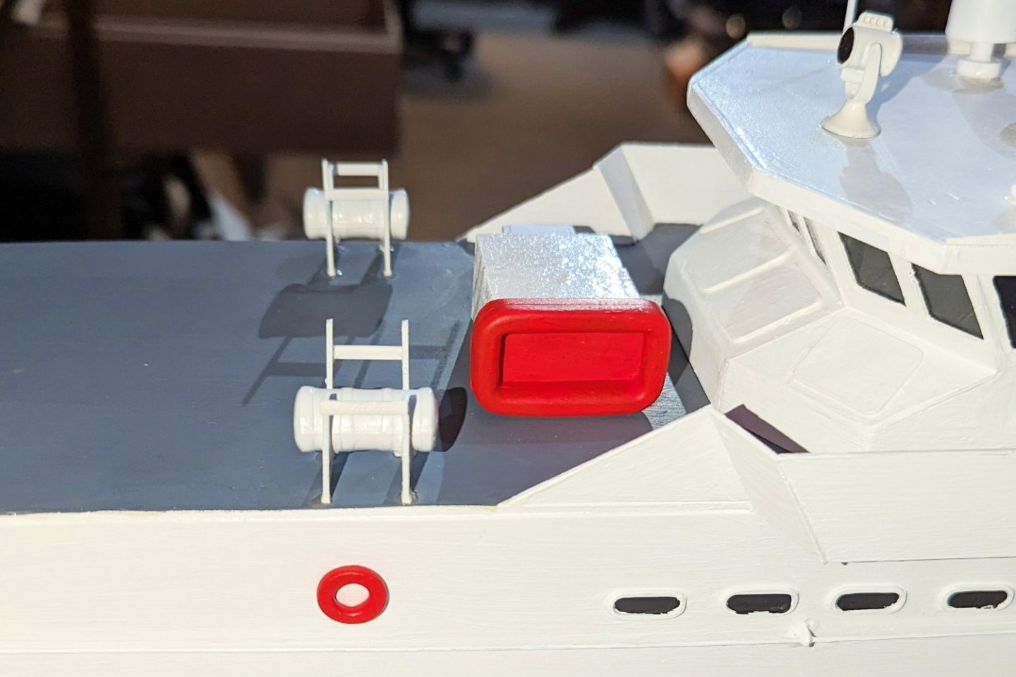
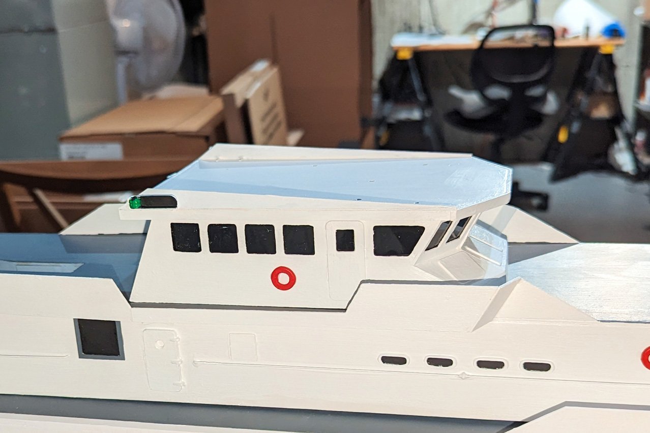
Lots of deck fittings added: Air vents Whip antennas Radar domes, radio antenna, searchlights Inflatable life rafts; rigid life raft Ammo lockers Flag Regards, David


- 46 replies
-
- 7
-
-
- Fast Response Cutter
- Dumas
- (and 2 more)
-
Thanks, Bob. That's really interesting stuff. Once I have the model completed and have completion pics, I might give them a call. As a USCG alum, are you thinking about building this one at some point in the future? Regards, David
- 46 replies
-
- 4
-
-
- Fast Response Cutter
- Dumas
- (and 2 more)
-
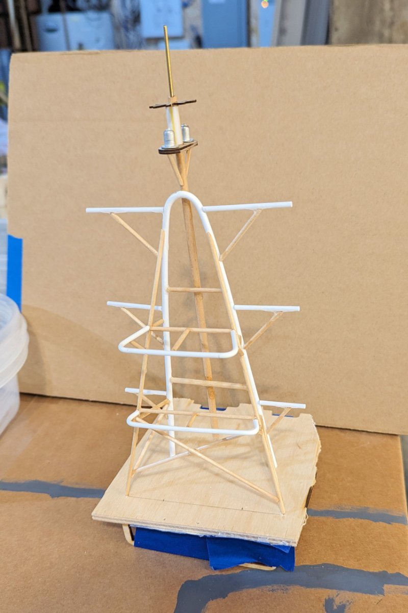
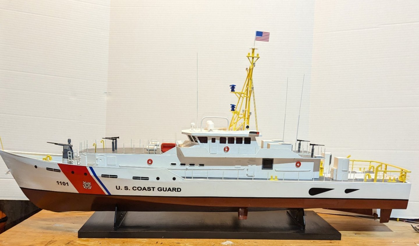
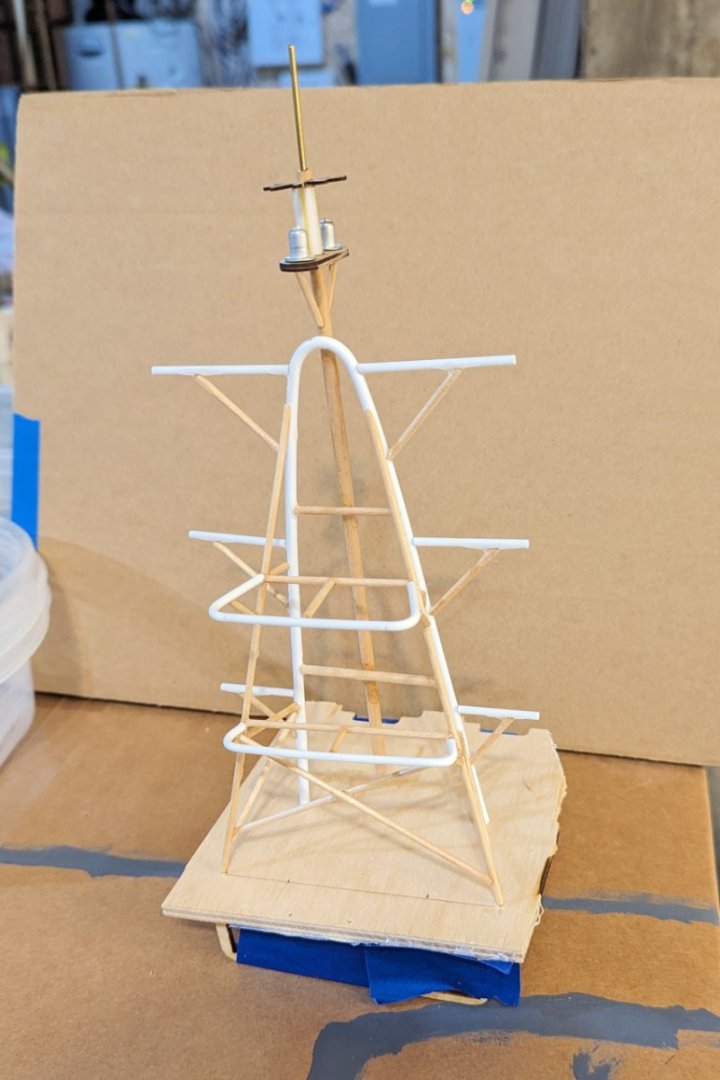
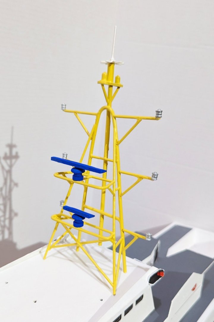
Finished the somewhat complex radar structure. As you can see, it's made up from a combination of styrene tubes and wood dowels. A few construction notes: It's just a bit oversized. That's due to a gap between the instructions and the diagrams. For those who might follow, the thing I didn't do was to resize the basic A-frame (before any bracing) to match the full size template. I cut it to the length specified in the instructions, and that's a bit too long. I then added braces, and only discovered that it was oversized as I got into the detail. Not a big deal. If you follow the instructions, the whole thing would be yellow. But the box art shows the white top, blue radars and silver (e.g. unlit white) sidelights. So I resequenced things to match the box art, which i smore interesting. Regards, David
- 46 replies
-
- 7
-
-
- Fast Response Cutter
- Dumas
- (and 2 more)
-
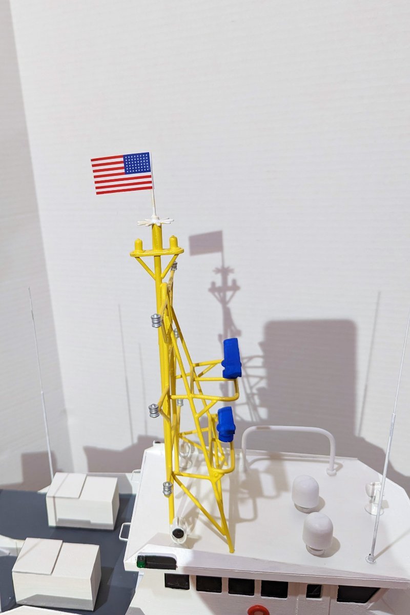
Thanks to Javelin, I got my head screwed on straight and have now fixed the running light positions. Regards, David
- 46 replies
-
- 8
-
-
- Fast Response Cutter
- Dumas
- (and 2 more)