James H
-
Posts
6,142 -
Joined
-
Last visited


.thumb.jpeg.fc5d633a7b34428fcf19419a73d56d55.jpeg)


About James H

- Birthday 02/26/1970


-
 KARAVOKIRIS reacted to a post in a topic:
HMS Surprise 1796 (prototype) by James H - Vanguard Models - 1:64
KARAVOKIRIS reacted to a post in a topic:
HMS Surprise 1796 (prototype) by James H - Vanguard Models - 1:64
-
KARAVOKIRIS reacted to a post in a topic:
HMS Surprise 1796 (prototype) by James H - Vanguard Models - 1:64
-
KARAVOKIRIS reacted to a post in a topic:
HMS Surprise 1796 (prototype) by James H - Vanguard Models - 1:64
-
KARAVOKIRIS reacted to a post in a topic:
HMS Surprise 1796 (prototype) by James H - Vanguard Models - 1:64
-
 Keith Black reacted to a post in a topic:
Spam in member message section?
Keith Black reacted to a post in a topic:
Spam in member message section?
-
 Zvr reacted to a post in a topic:
HMS Surprise 1796 (prototype) by James H - Vanguard Models - 1:64
Zvr reacted to a post in a topic:
HMS Surprise 1796 (prototype) by James H - Vanguard Models - 1:64
-
James H reacted to a post in a topic:
Syren Ship Model Company News, Updates and Info.....(part 2)
-
Matt D reacted to a post in a topic:
HMS Surprise 1796 (prototype) by James H - Vanguard Models - 1:64
-
AJohnson reacted to a post in a topic:
HMS Surprise 1796 (prototype) by James H - Vanguard Models - 1:64
-
AJohnson reacted to a post in a topic:
HMS Surprise 1796 (prototype) by James H - Vanguard Models - 1:64
-
James H reacted to a post in a topic:
HMS Surprise 1796 (prototype) by James H - Vanguard Models - 1:64
-
James H reacted to a post in a topic:
HMS Surprise 1796 (prototype) by James H - Vanguard Models - 1:64
-
 Yes....ASAP. Real life sometimes gets in the way, especially as I work full time in an extremely stressful job. There are times I'm too mentally (and physically) drained to operate properly. Today has been a particularly bad day......but it's Saturday tomorrow, and I have plenty planned for the weekend.
 -
James H reacted to a post in a topic:
HMS Surprise 1796 (prototype) by James H - Vanguard Models - 1:64
-
There will definitely be an update this weekend. Surprise is under paint and I've been working on exterior stuff, so that's what you'll see next. Coppering is imminent too. Initial production will be circa 100 kits, but that's a rolling production as when things get down to low numbers, then you can guarantee the next series of parts are being produced.
-
I would suggest to everyone that if someone unknown to you is asking for anything such as plans etc. PLEASE report them to us and we will deal with it. I've just banned a member called 'Schlonmann' who has sent almost THIRTY members a message, asking for copies of plans for models they have either worked on or are still building. We won't tolerate this.
- 3 replies
-
- 19
-
-
-
-
I always use a pin pusher on my first layer of planks on POB models. I'm using a Modelcraft tool from Vanguard Models, and also Amati pins which are very fine. These go through the timer easily. If there's resistance, I will drill a tiny pilot hole first.
-
James H reacted to a post in a topic:
USS Bagley (DD-386) by catopower - 1/200 - Avangard - CARD
-
James H reacted to a post in a topic:
HMS Victory: Caldercraft or Artesania Latina
-
Love to see your build here too.
-
James H reacted to a post in a topic:
Kawasaki Ki-61 Hien "Tony" by ccoyle - Halinski/Kartonowy Arsenal - 1/33 - CARD
-
This is alchemy 😆
-
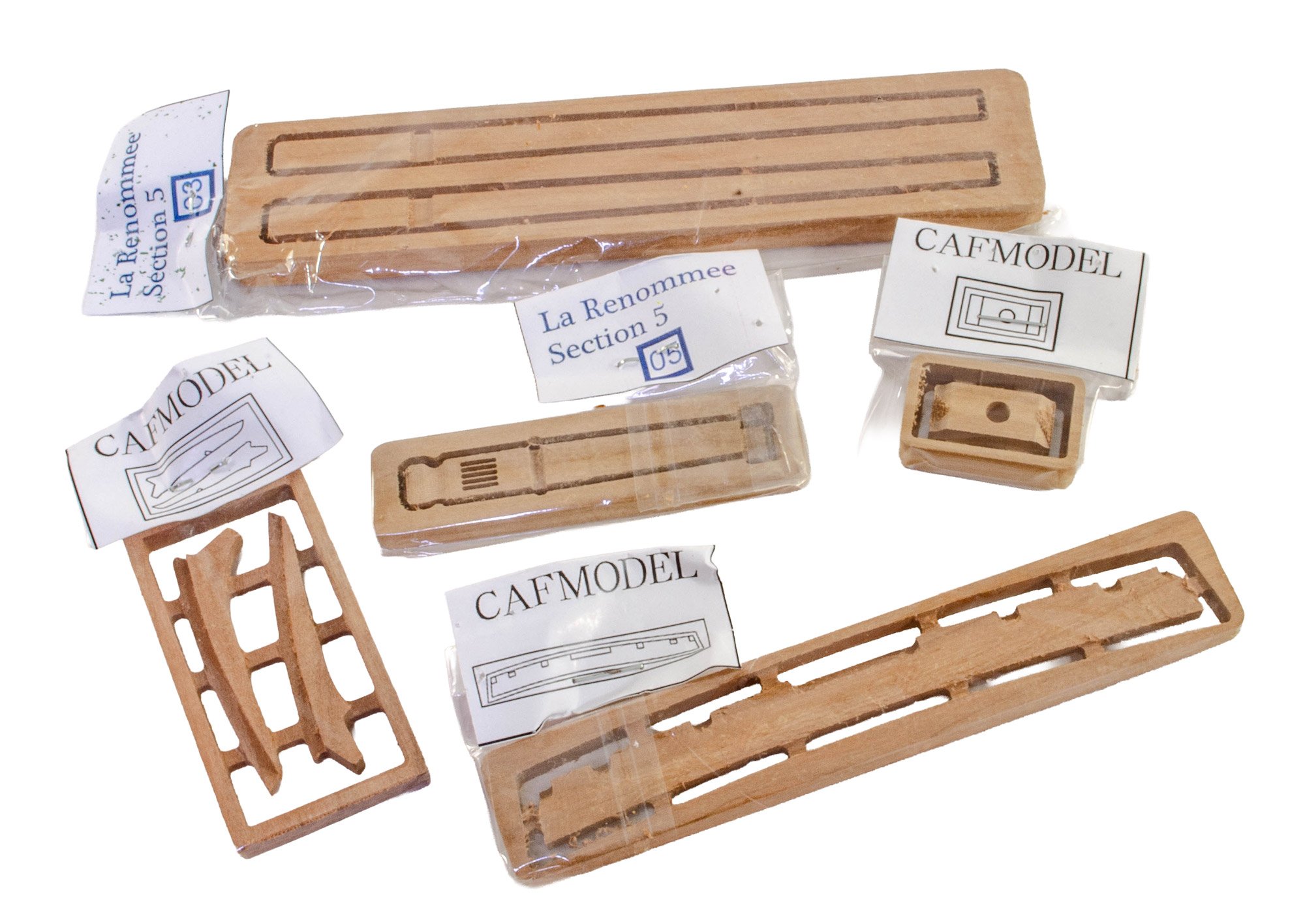
kit review 1:48 La Renommée 1744 - CAF Model
James H replied to James H's topic in REVIEWS: Model kits
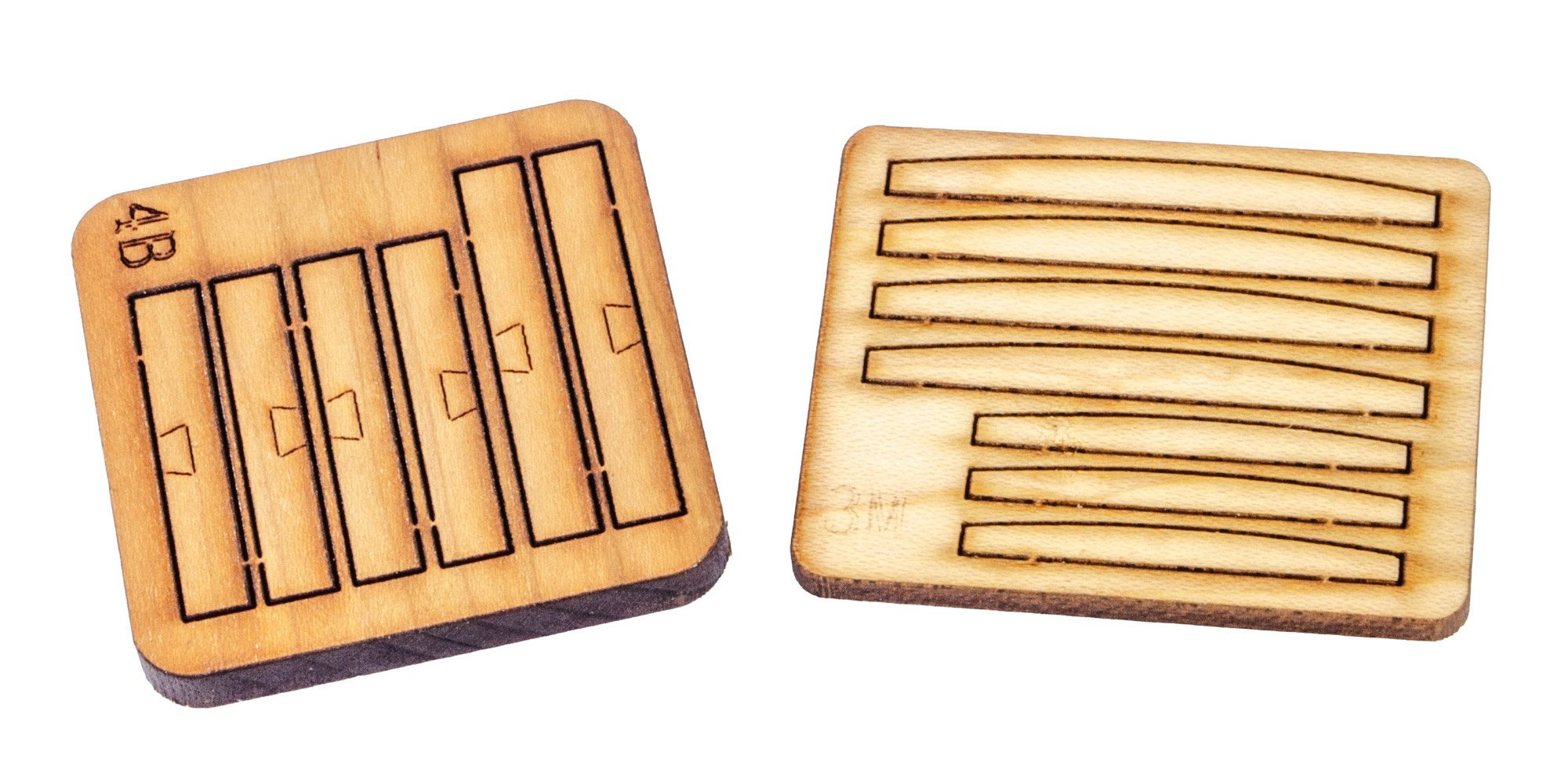
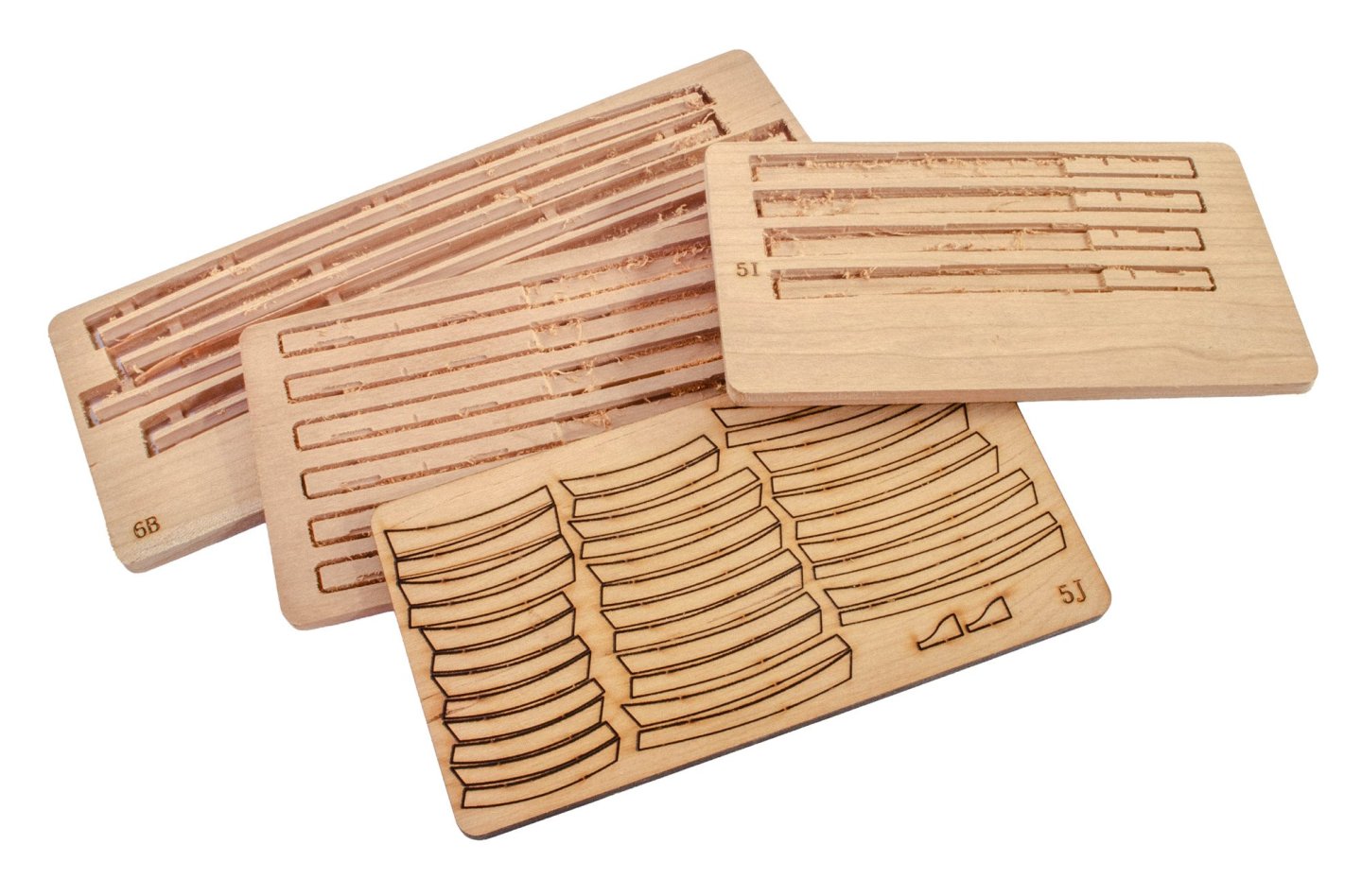
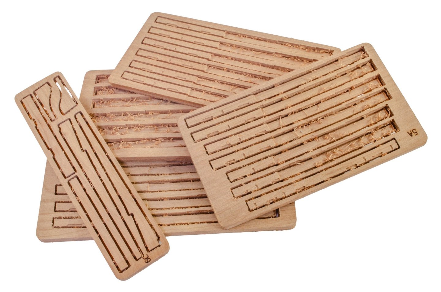
These tend to be the thicker sheets. Use of multi-axis CNC is used to create parts that would be more challenging to produce from plan sheets showing various profiles.- 20 replies
-
- 5
-
-
- cafmodel
- la renommee
- (and 1 more)
-
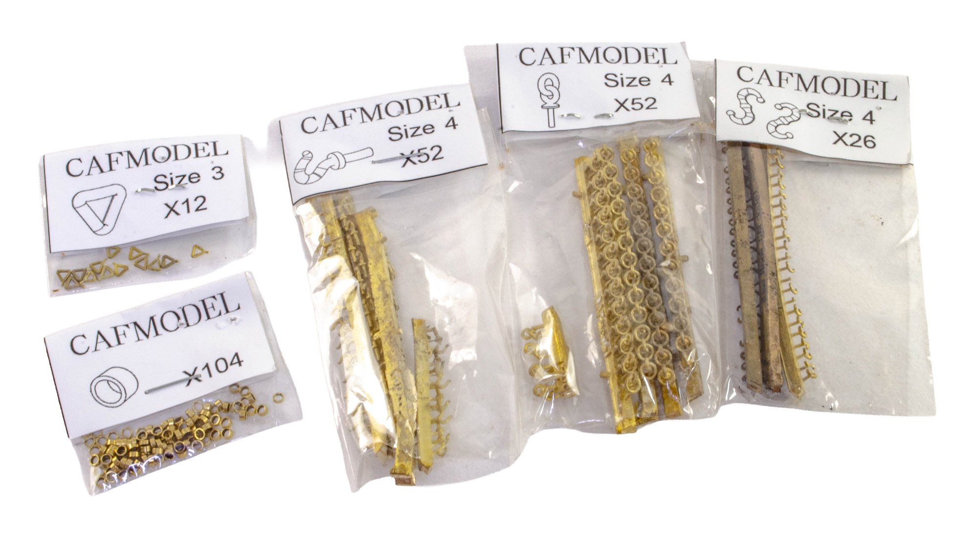
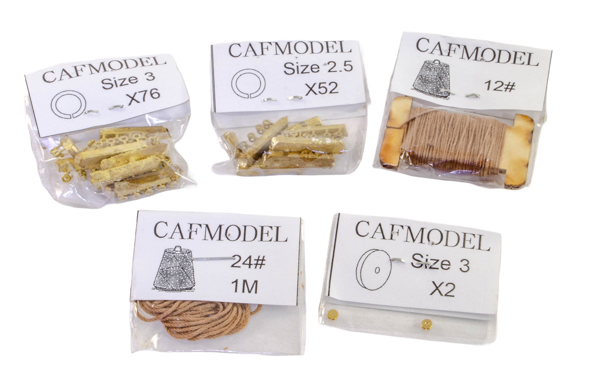
kit review 1:48 La Renommée 1744 - CAF Model
James H replied to James H's topic in REVIEWS: Model kits
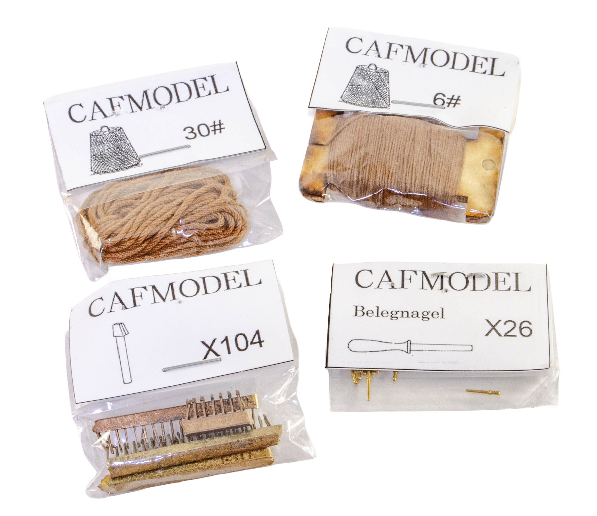
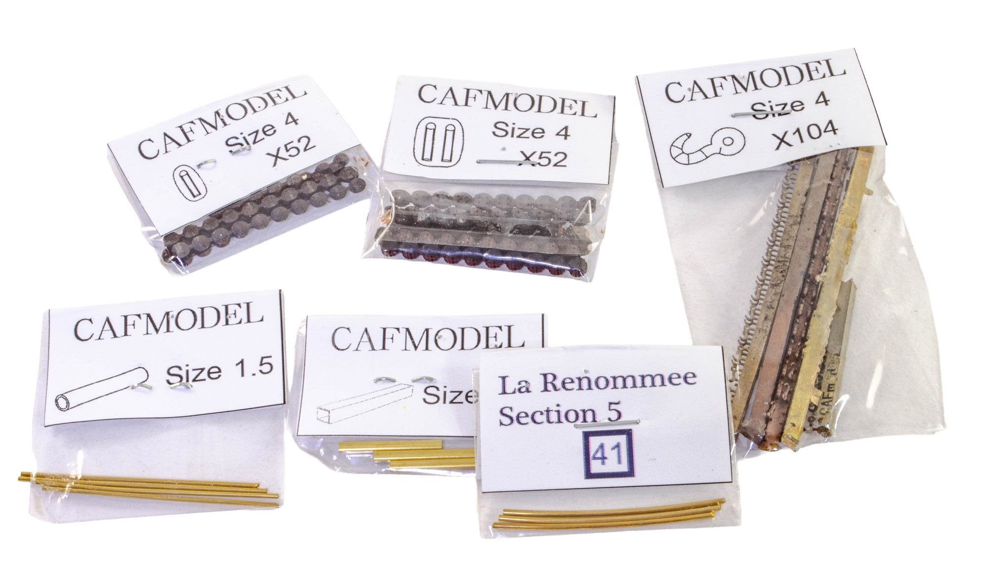
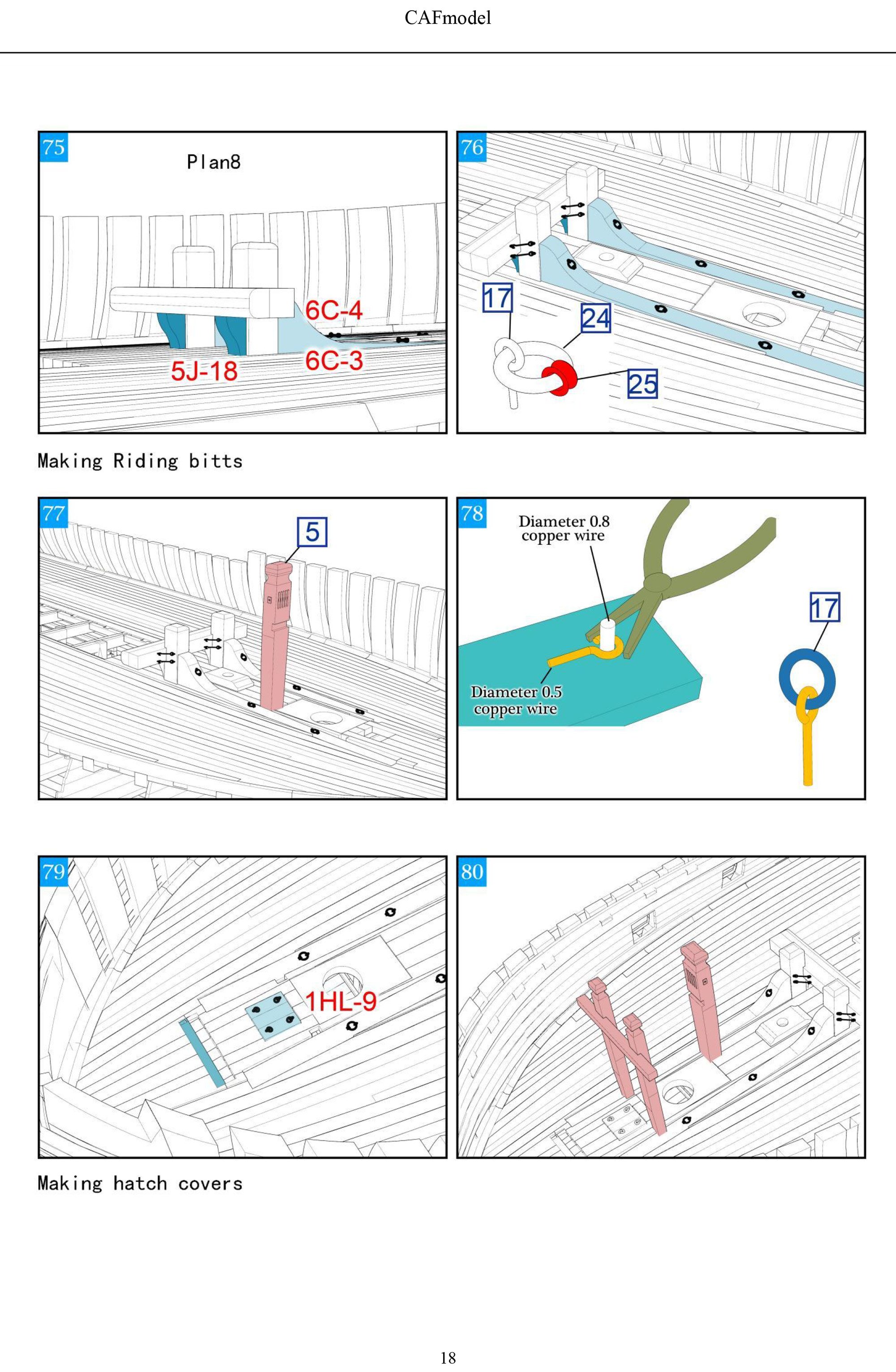
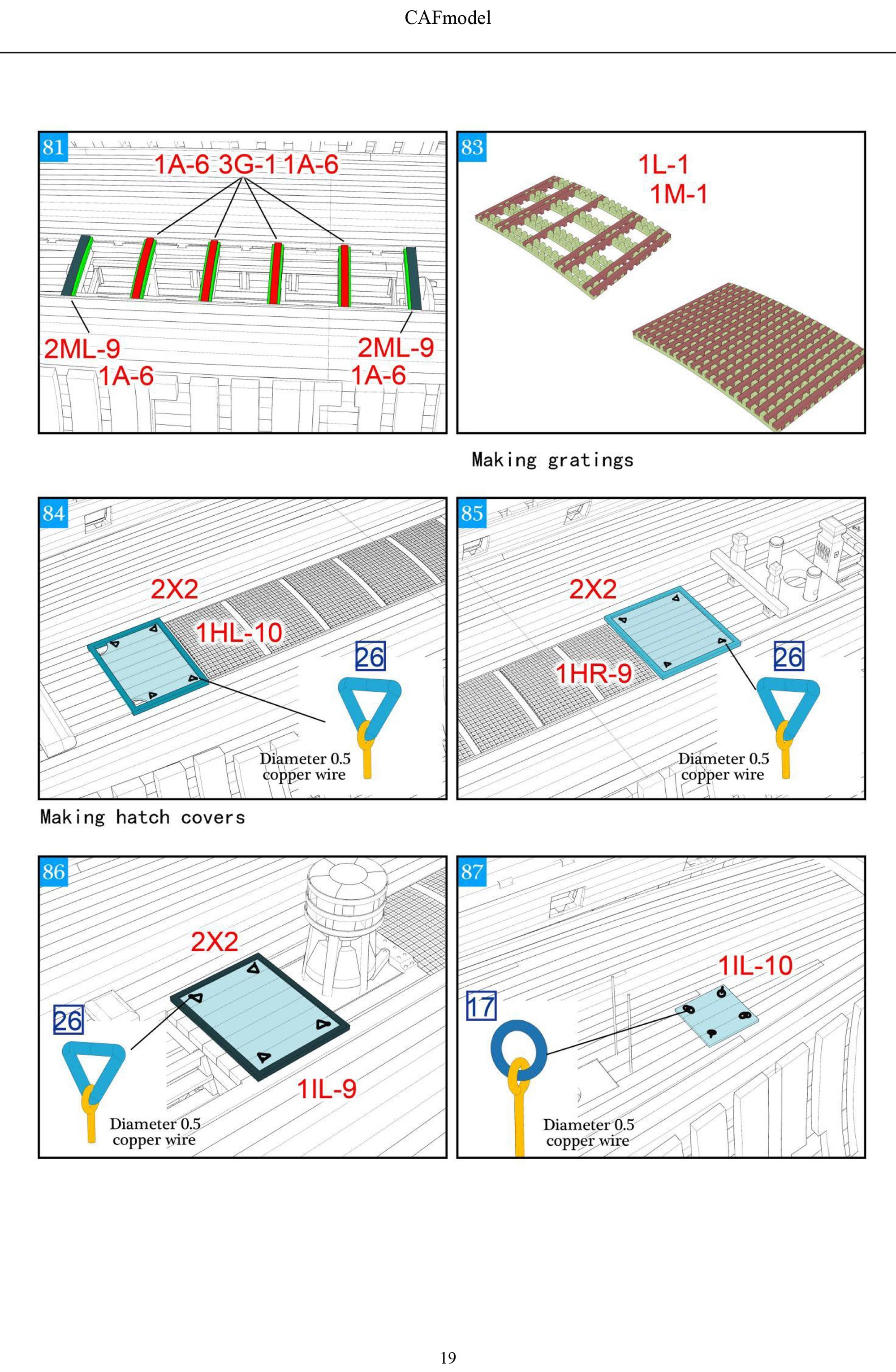
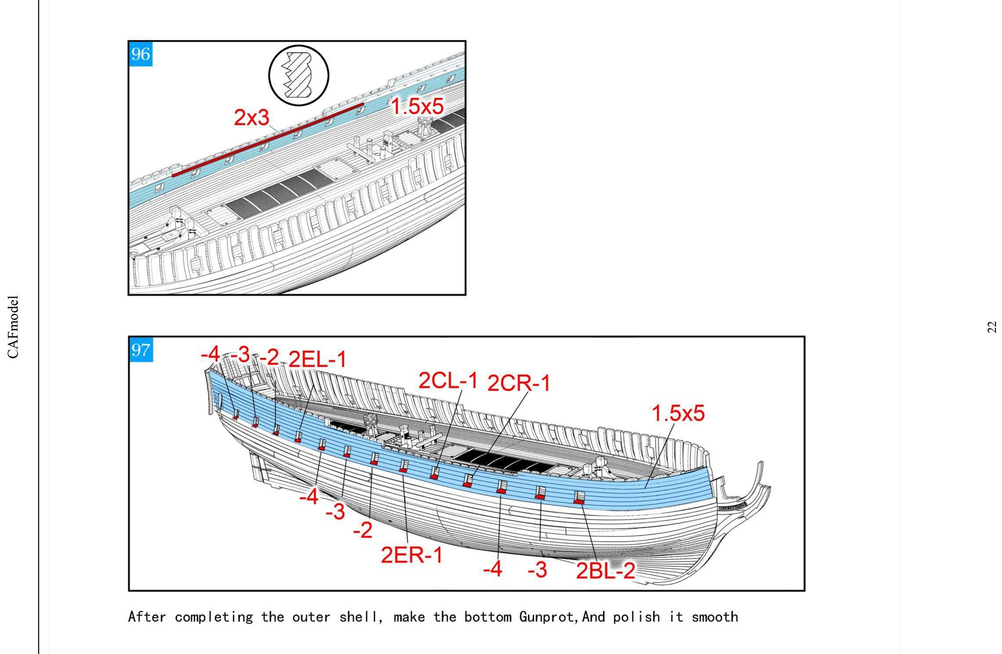
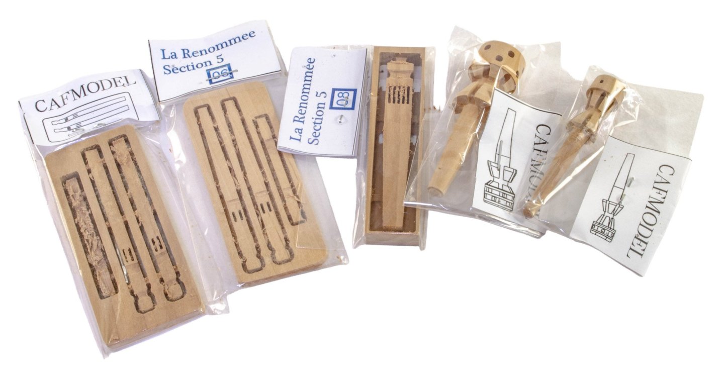
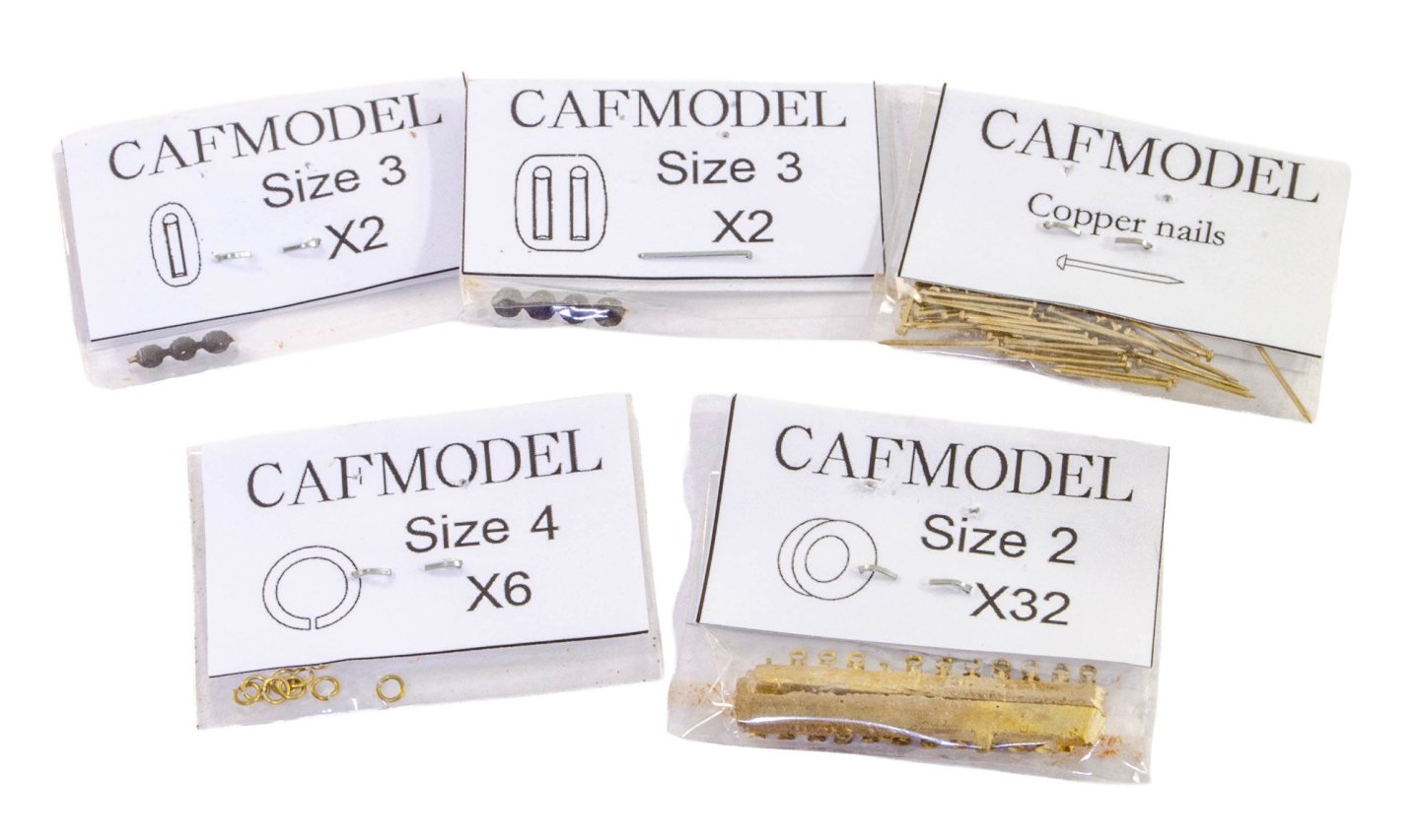
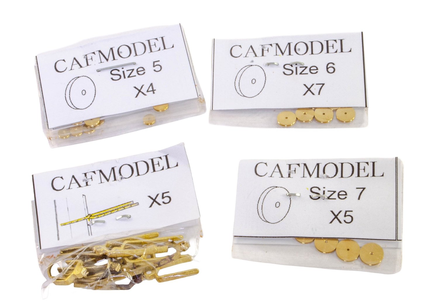
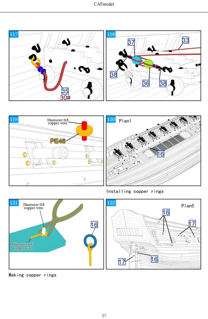
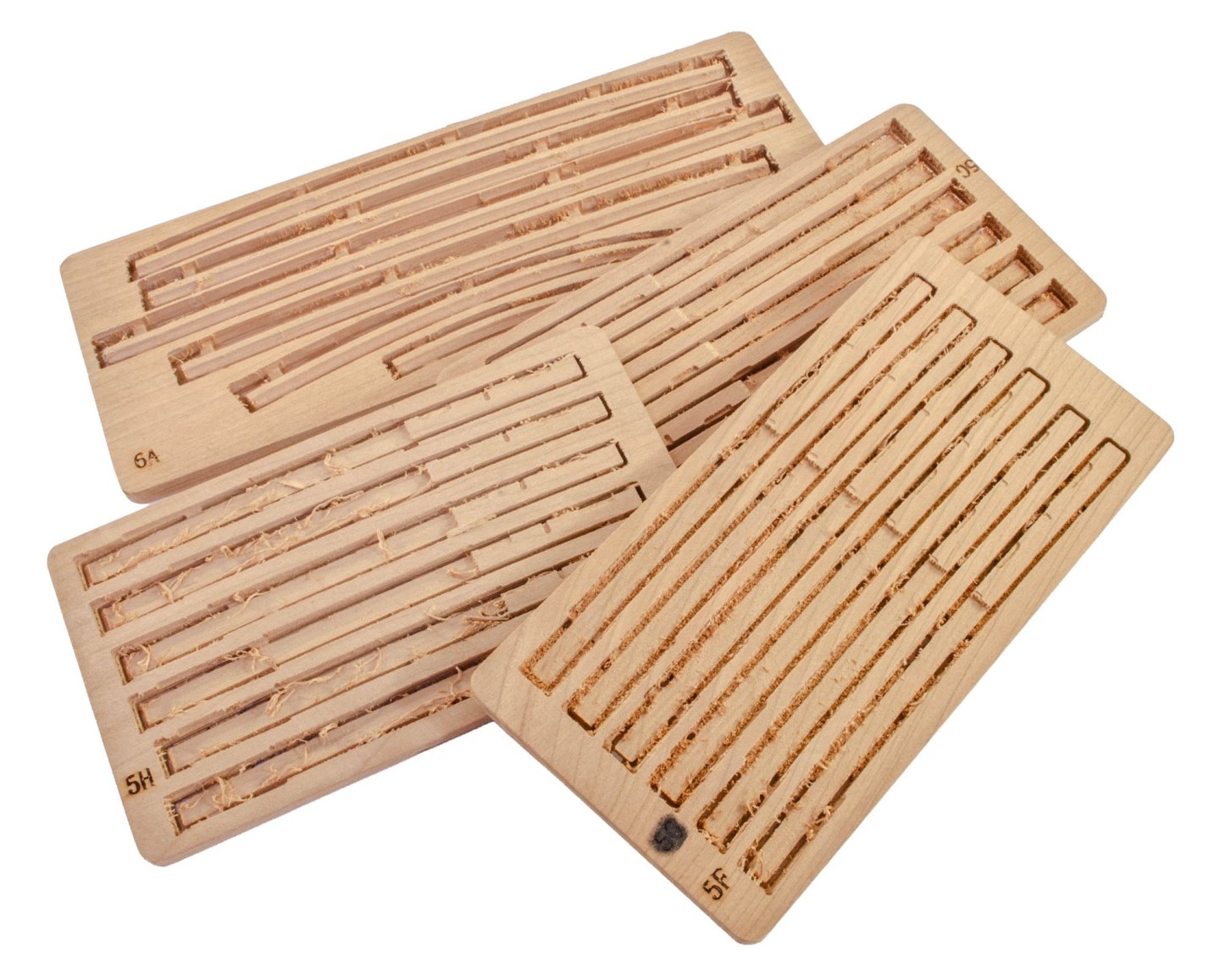
I did say a number of the CNC-milled parts were packaged separately, and here they are. These parts generally have more work on them by means of a multi-axis approach, shaping some quite complicated parts and taking the guesswork out of trying to visually fathom parts from multiple profile drawings. CAF seem to use a lot of lost wax casting for their brass fittings, and the production is very good indeed. You will of course need to clip the parts from the sprues, and then file away any remnant of the connection point. Here you can see the variety of brass parts included. Wooden rigging blocks are included for the cannon, and the rigging cord appears to be a decent quality too, with no fuzziness. Individual brass sheaves are also included for those machined bitts, and wire to mount them. Cannon! The photo actually doesn't show these in their best light. They are very well made, complete with crests. Photo Etch. This is the strip and dowel timber supplied. The big bungle consists of many strips, and all timber is nicely cut with no bad edges, ends or splits. INSTRUCTIONS Readers are best taking a look at the link I previously posted, which will give you a look at the whole manual. Here are a few sample images though. The final set, Pack 6, will follow in a week or so.


- 20 replies
-
- 9
-
-
- cafmodel
- la renommee
- (and 1 more)
-
kit review 1:48 La Renommée 1744 - CAF Model
James H replied to James H's topic in REVIEWS: Model kits
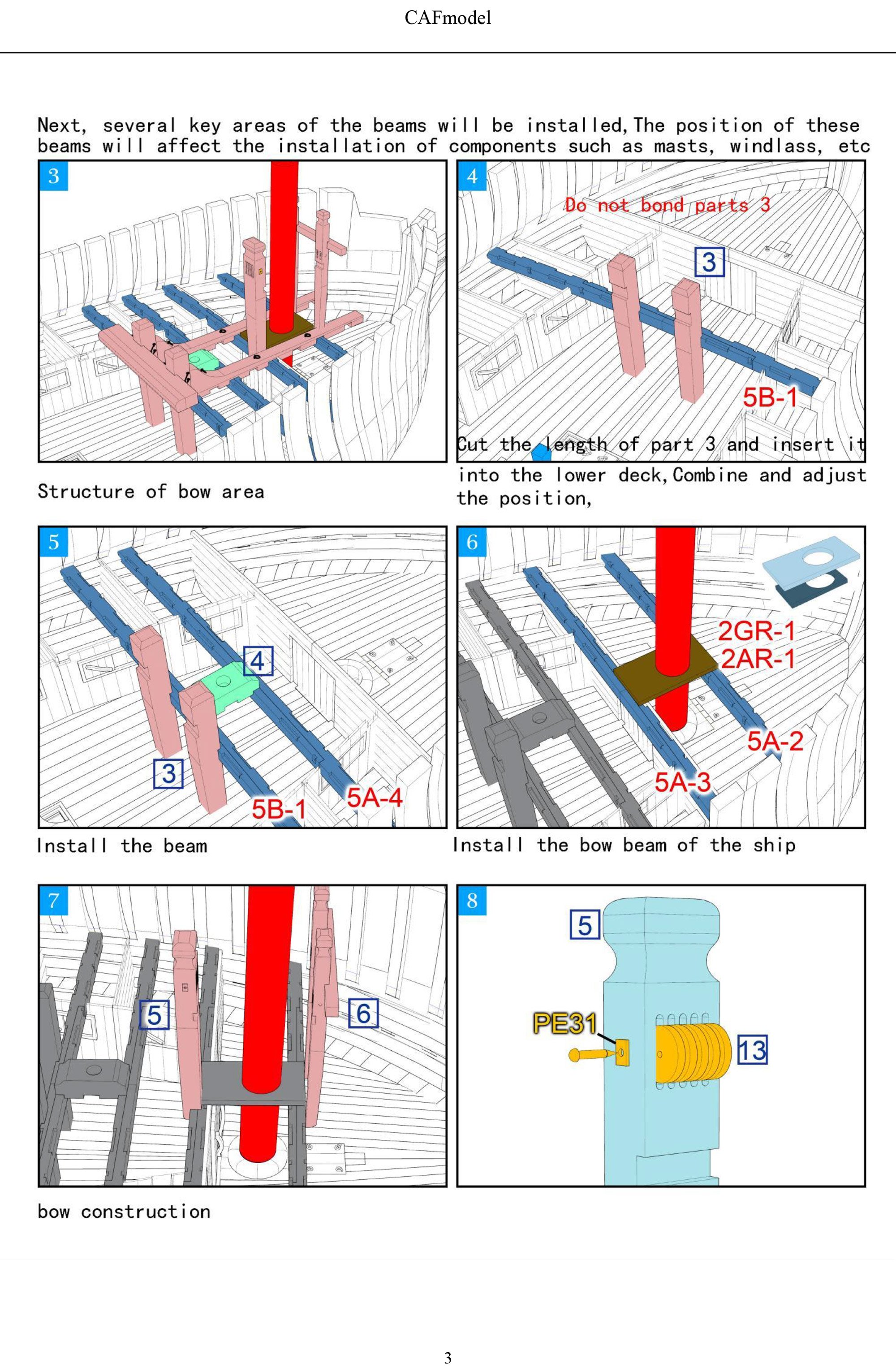
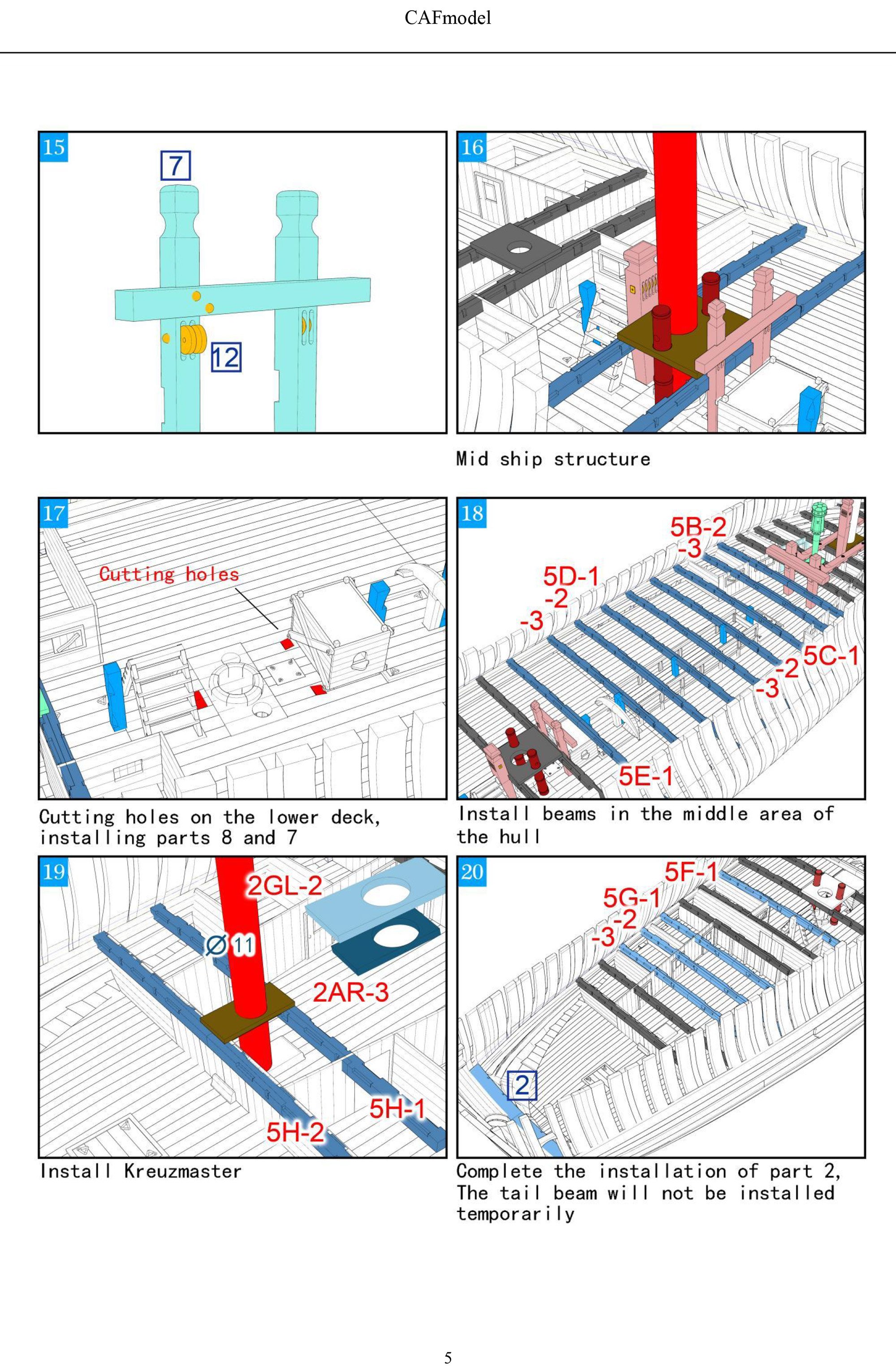
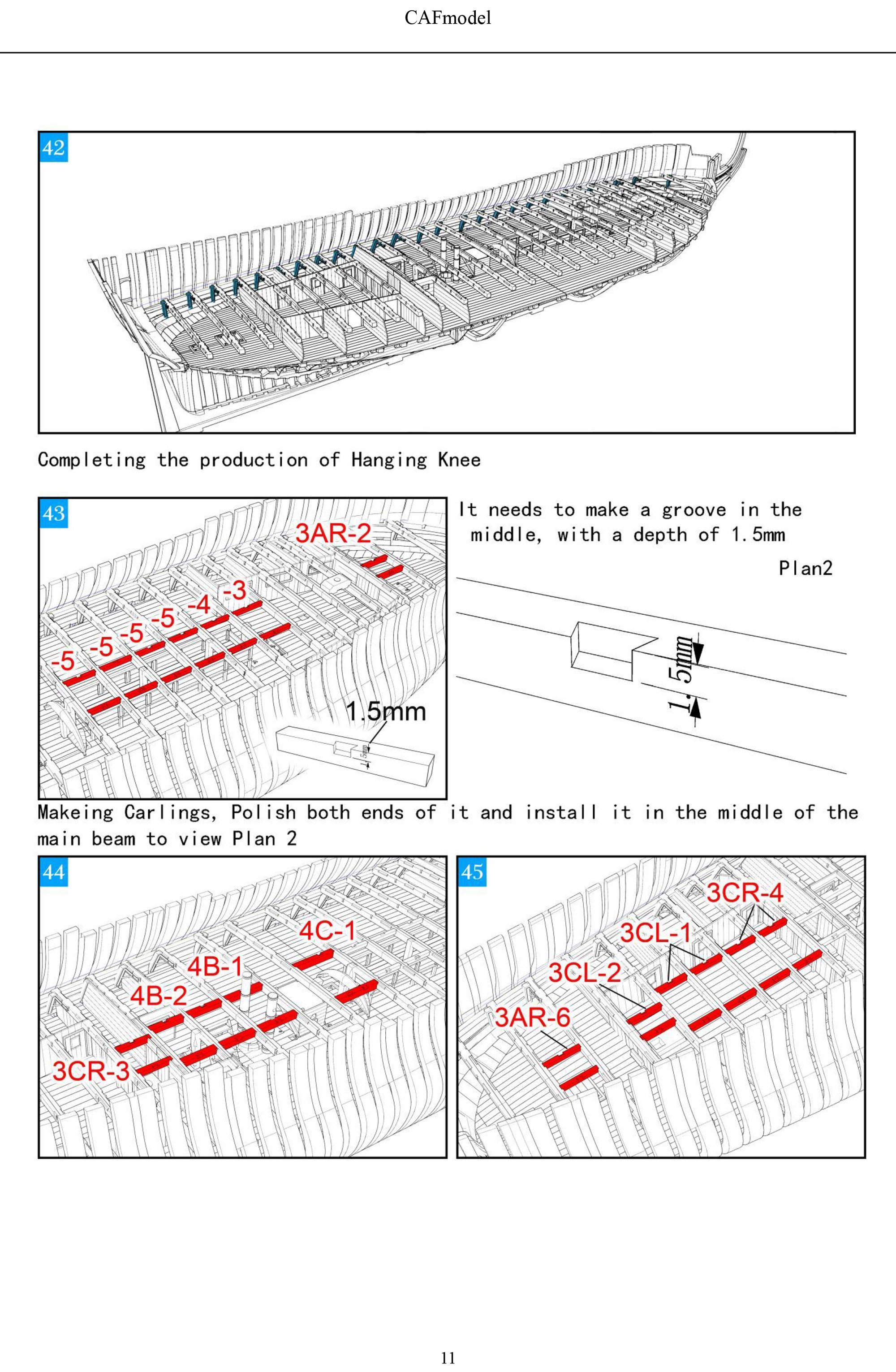
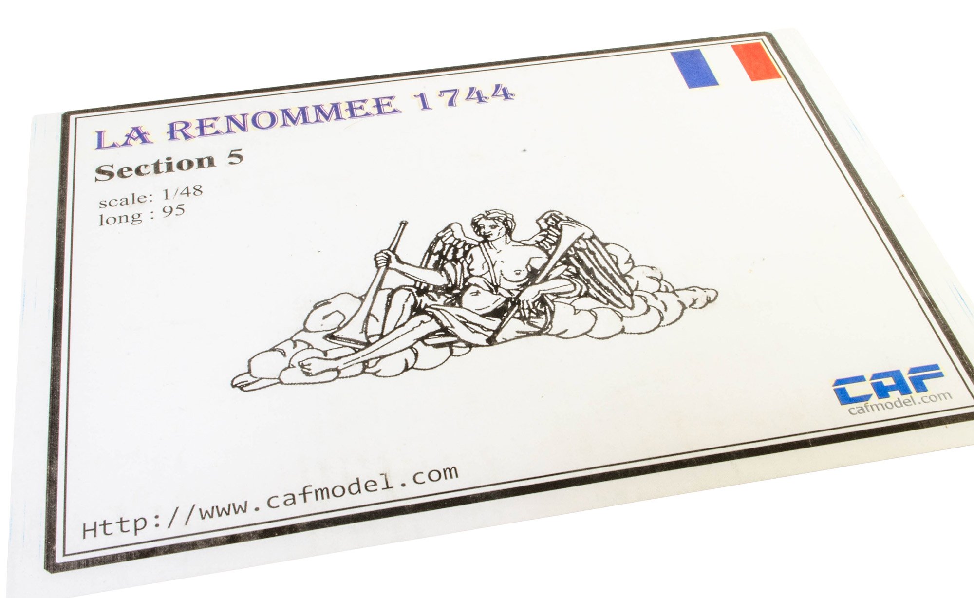
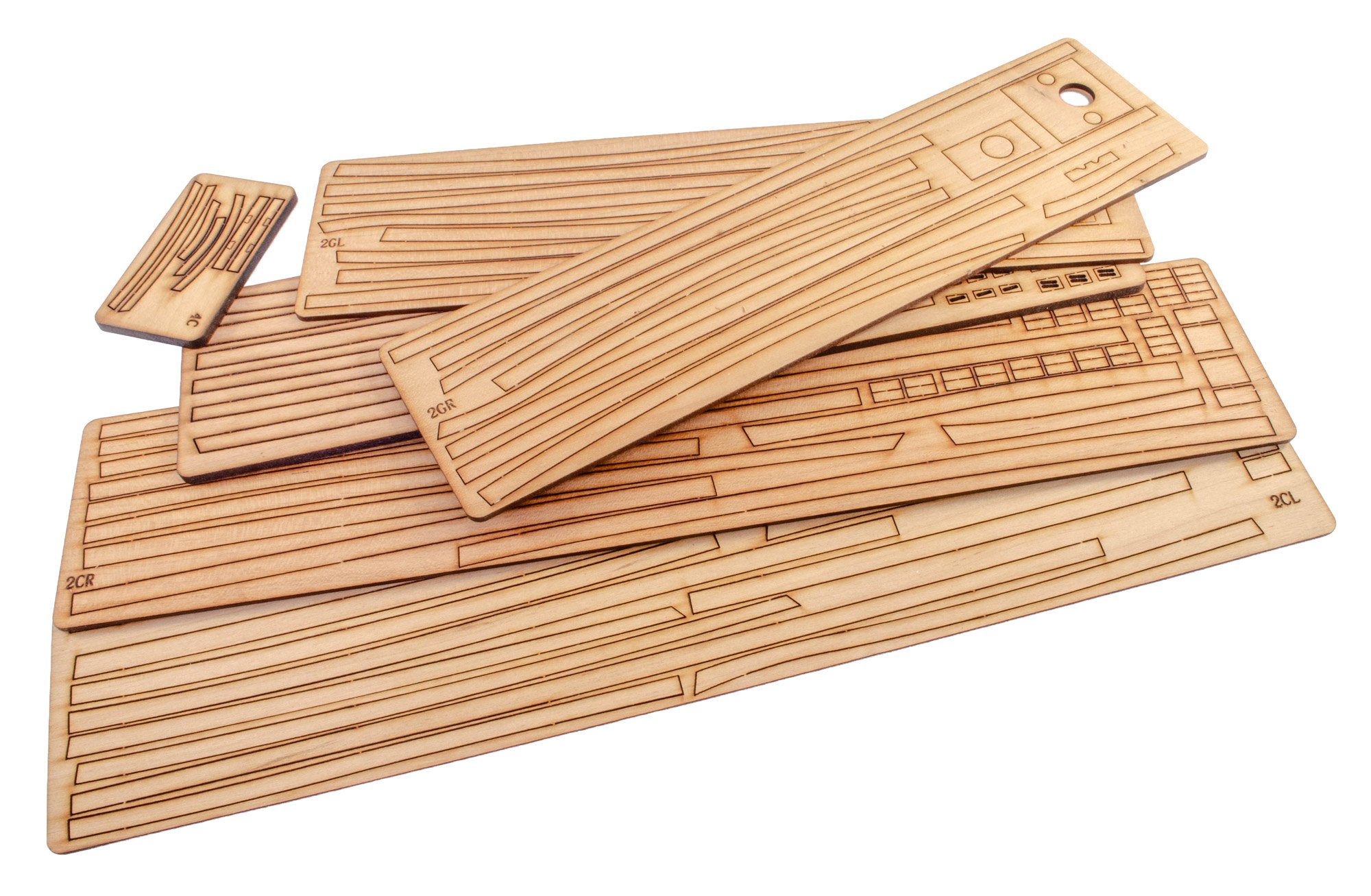
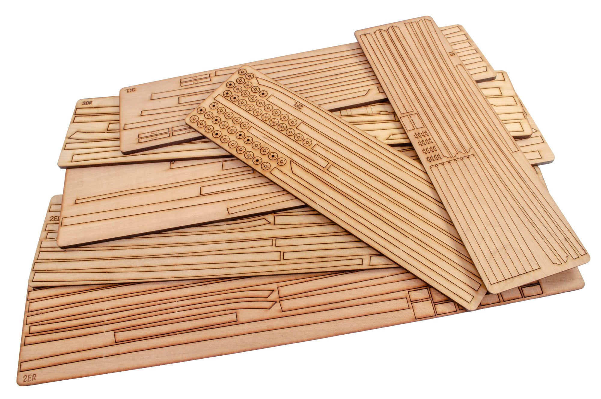
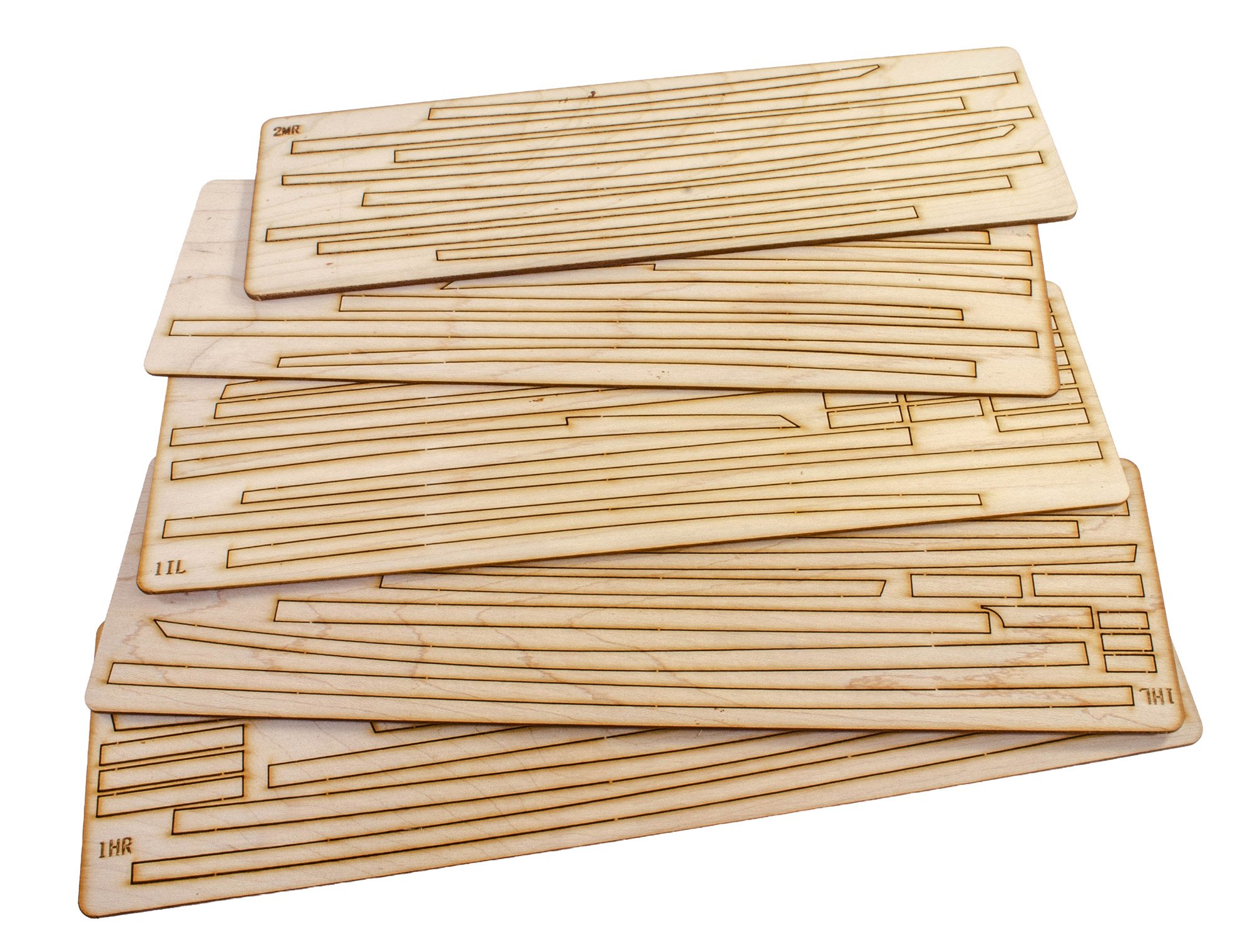
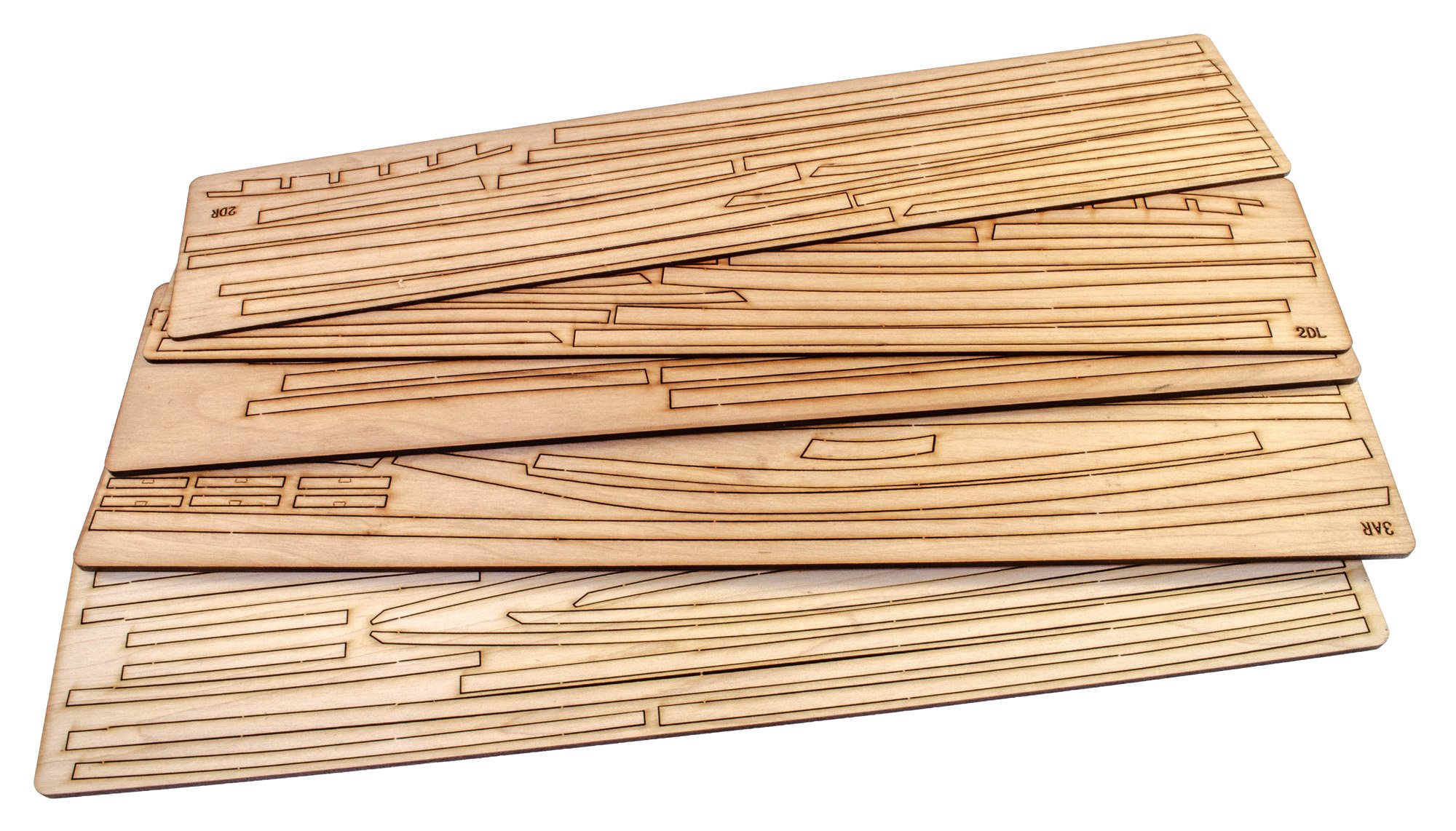
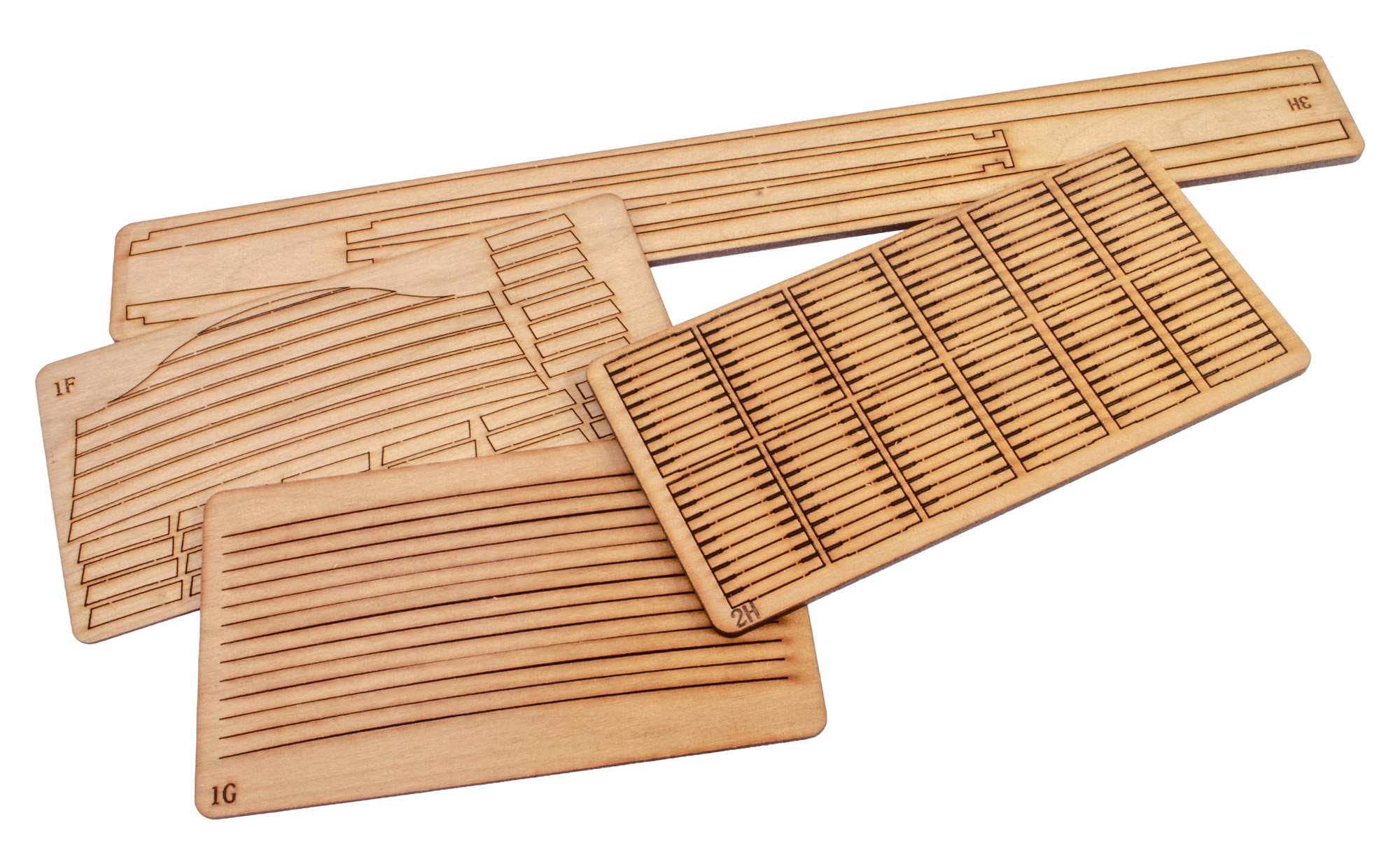
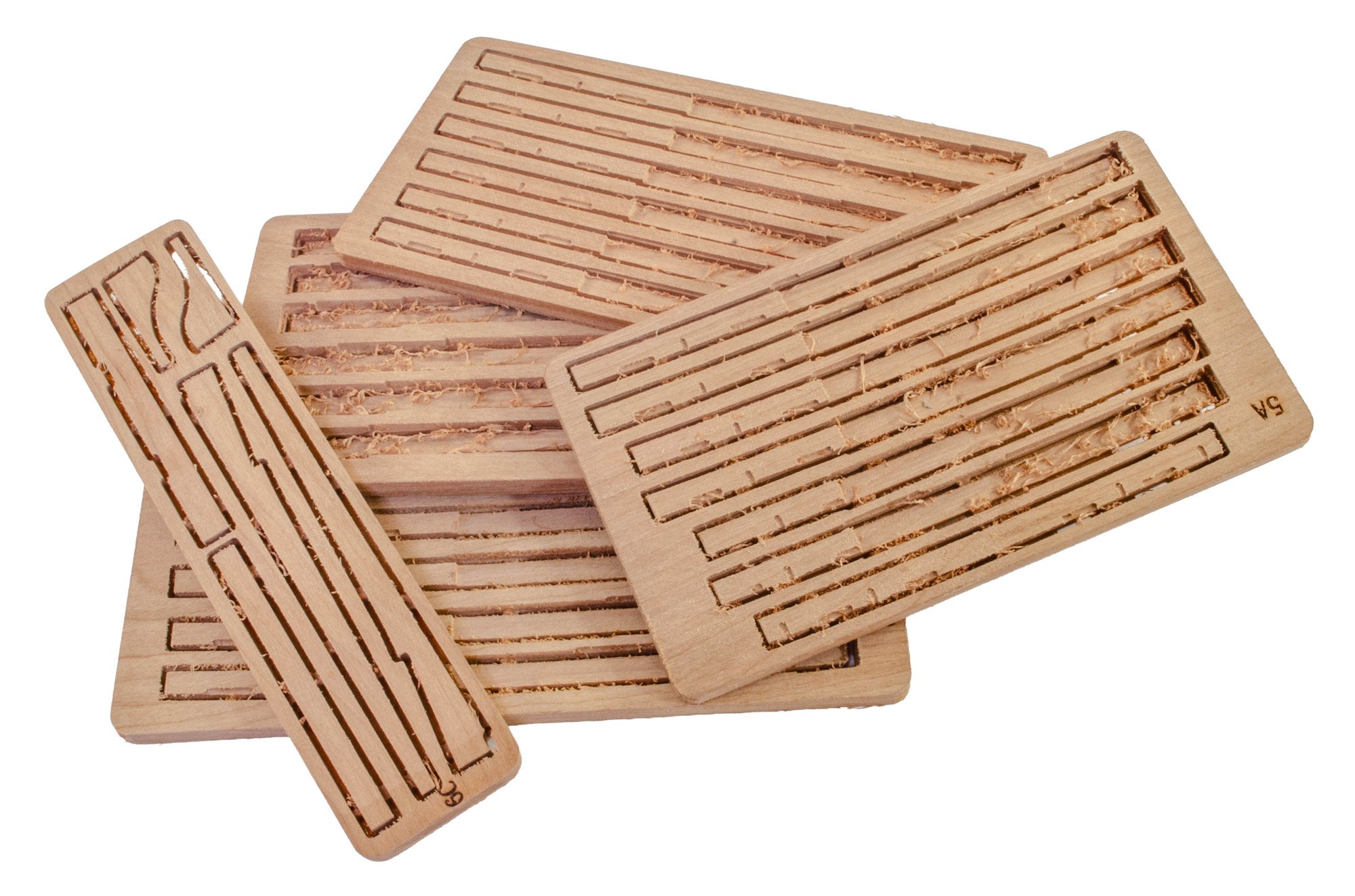
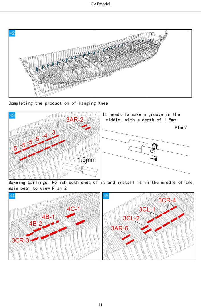
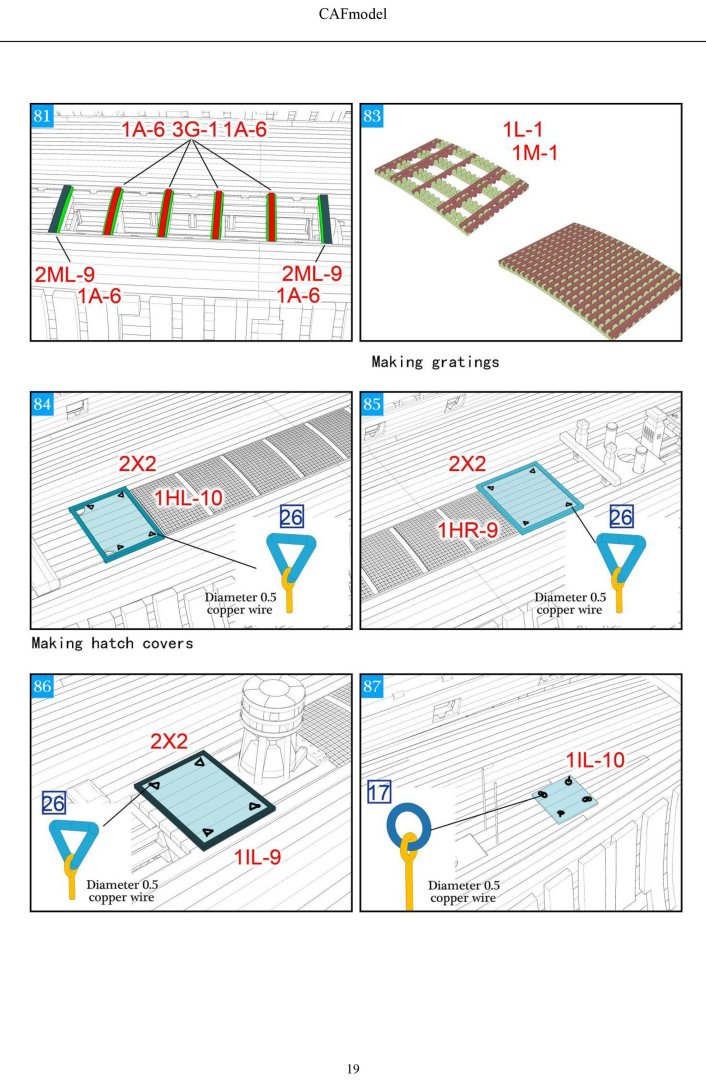
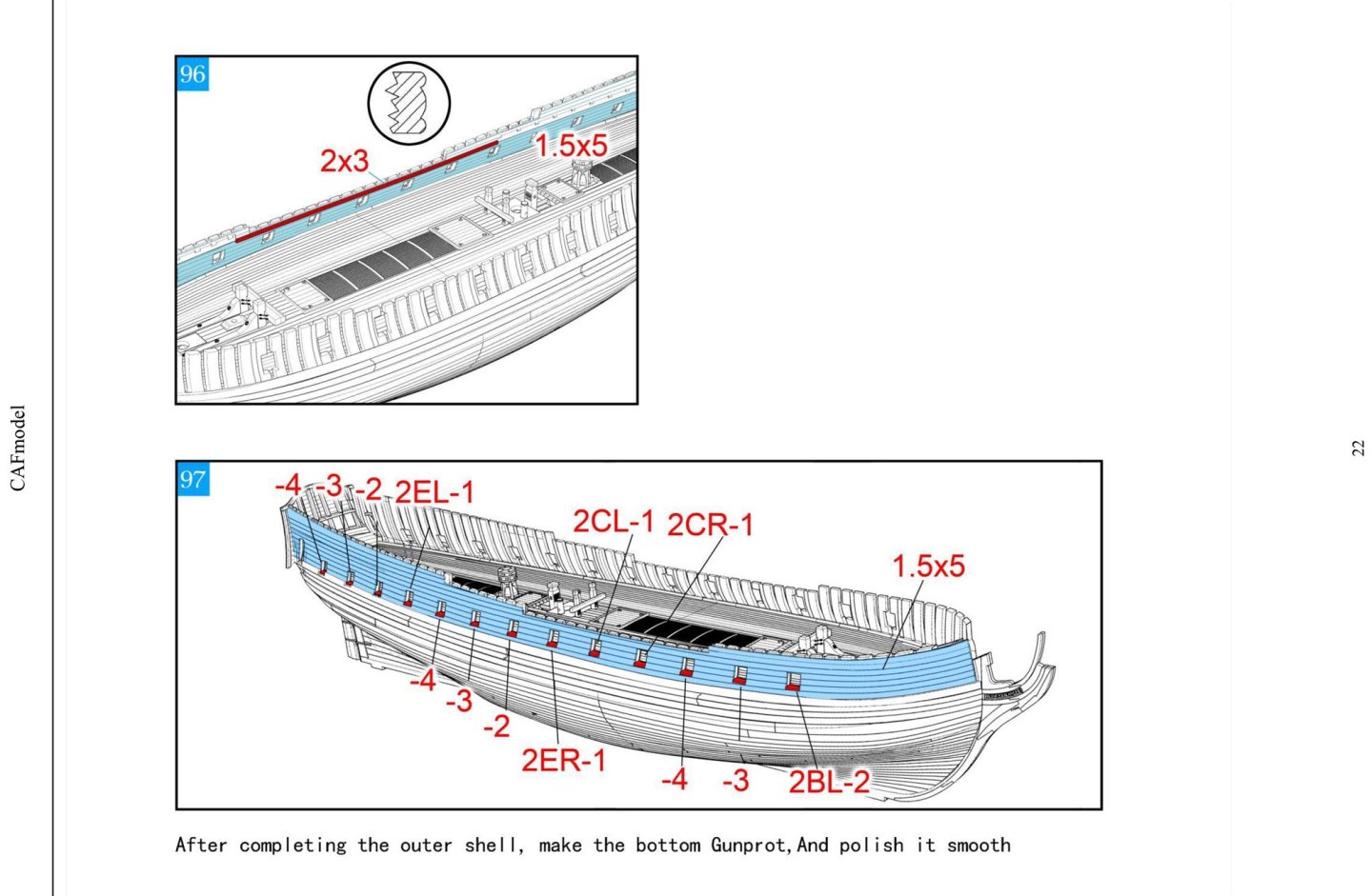
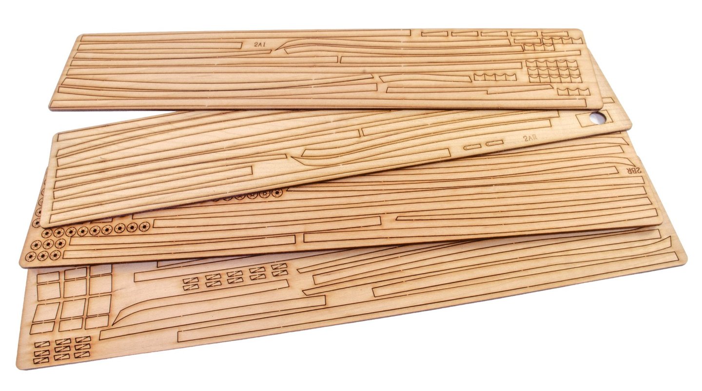
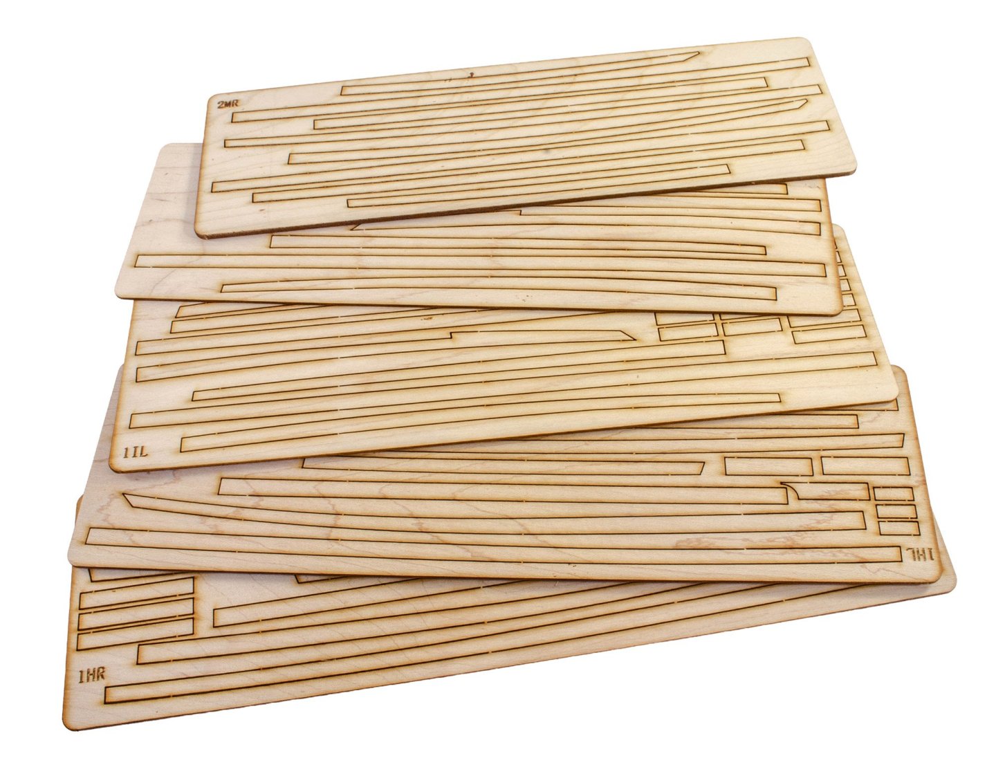
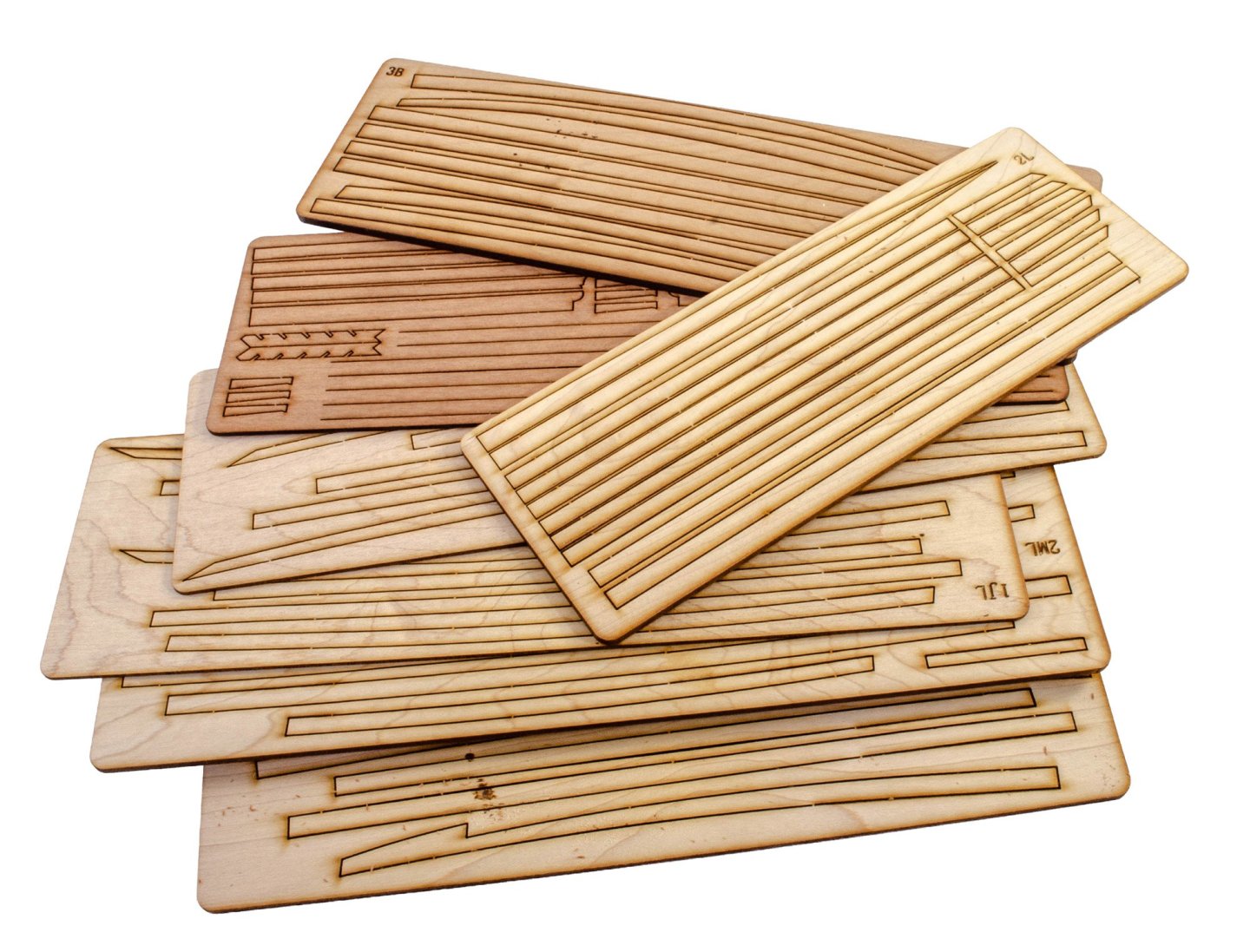
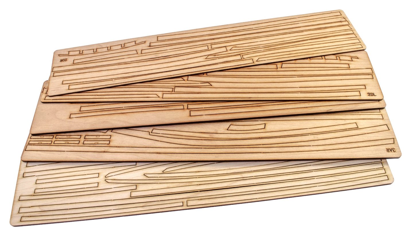
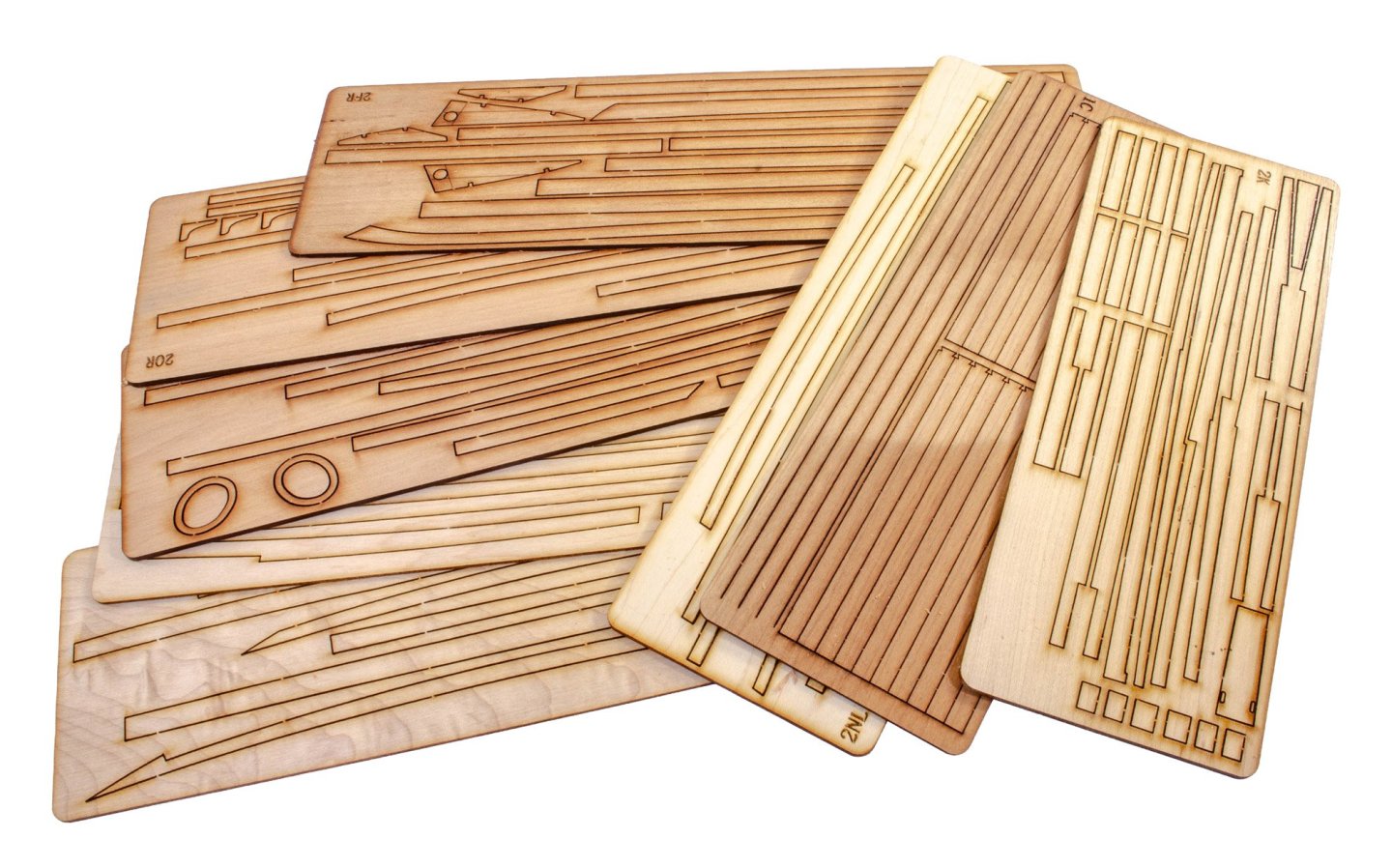
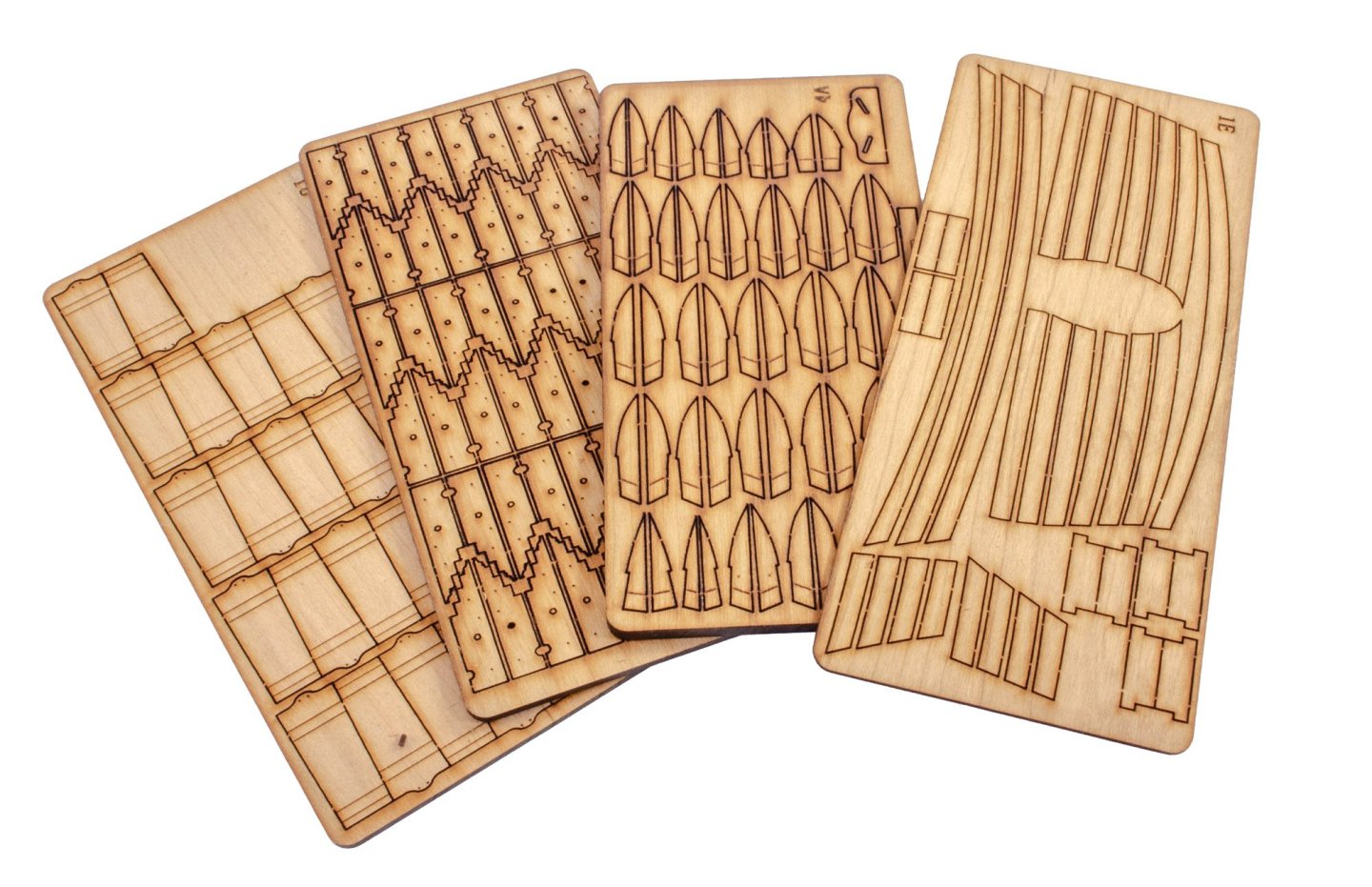
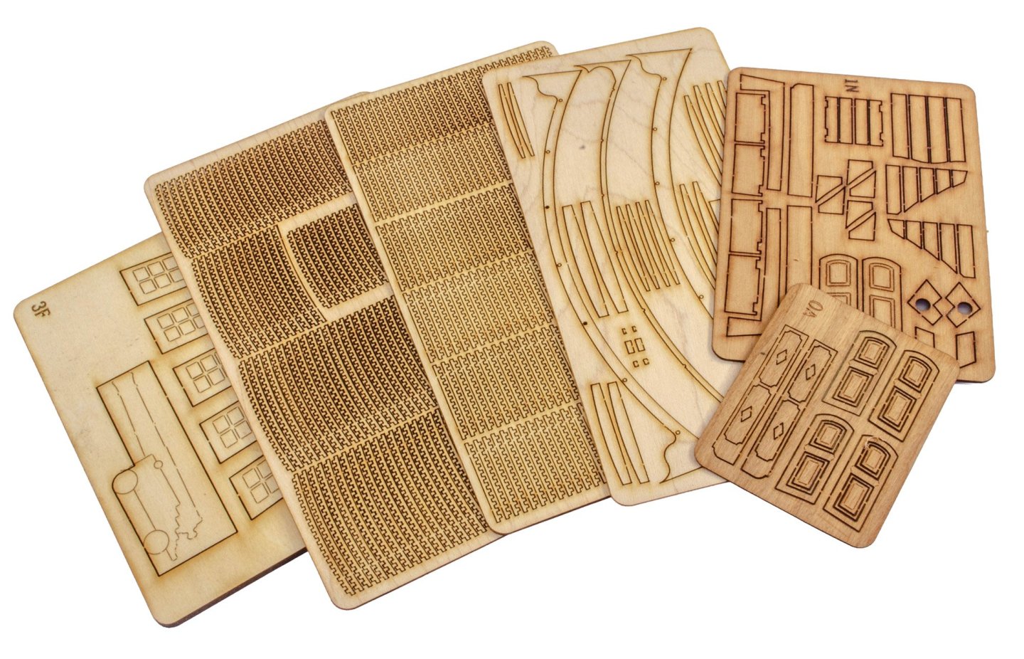
PACK 5 This pack isn't optional. It's very much needed for this project. Not only that, but I'm very confident that this is the heaviest of all the packs in this set. Some stats for you; there are almost SIXTY sheets of laser-cut parts. There are also about TWELVE spare sheets of CNC routed parts that occupy the regular pack of timber sheets. In addition to that, there are also TEN individually bagged CNC-shaped parts, including bitts and capstans. Also included is rigging cord, lost-wax brass castings, wooden rigging blocks and wire. A pack of strip wood, large sheet of PE, brass cannon, manual and plans complete this very detailed pack. Laser cutting, again, is very good, and rear scorching will be easy to remove. For all of these sheets, I would give both sides a sanding in fine and then superfine grit paper so get the best out of the cherry wood utilised in the kit. This is something I tend to do so that the timber colour shows through nicely and any resins released by the cutting process, are removed. Tom has made sure that the sheets are as uniform in colour as you can get from a natural product. Part sheets are numbered and those numbers are to be cross-checked against the parts maps supplied in the rear of the instruction manual. As shown in a previous post, there is some debris which needs removing from the milled parts sheets, but the parts themselves are perfectly good and won't need much more than regular clean up before use. Timber elements here include deck beams, furniture, partitions, gratings, deck planking etc. This comprehensive pack is best explained by taking a look at the manual itself, provided by CAF. While I include some photos in the next post, you can preview this pack by clicking THIS link. Continued....


- 20 replies
-
- 8
-
-
-
- cafmodel
- la renommee
- (and 1 more)
-
We've had a small number of members like that. They persisted in their arrogance, and they are now gone, being arrogant elsewhere.
-
Please check your email and pop me a PM to say you got it.
-
I don't know of a UK supplier any more. There used to be Modelling Timbers, but alas Keith has. now sadly passed. I can vouch for Hobbymill.eu. Their quality and cutting is superb and they're very reliable. @Wahka_est
-
Sort of. We came up with those skill levels as the more advanced kits still need the modeller to be able to think stages ahead and work that into their planning, irrespective of each of those subsequent photos being detailed. We ALWAYS suggest that anyone tackling a kit like Indefatigable, will be familiar with various building techniques through previous projects. That has to be our caveat. Much depends not only on previous experience, but also success. Of course, some modellers are absolute naturals and can build relatively complex models on their first foray, but many also fail to complete, or have a low level of success. If you go ahead and try Indy, then take your time and ask questions. Chris Watton is a member here, and I'm the guy who built that model for the instruction manual.