


thibaultron
-
Posts
2,676 -
Joined
-
Last visited
Reputation Activity
-

 thibaultron reacted to Harvey in Masking Problem
Hi
have a look at this
3M 471 Blue Fine Line Vinyl Masking Tapehttp://www.amazon.co.uk/Fine-Vinyl-Masking-Painting-Residue/dp/B00CUPL8BI
-
thibaultron reacted to mikiek in Masking Problem
Harvey - I am using Tamiya tape in various widths. Never heard of anti-bleeding tape.
-
thibaultron reacted to Harvey in Masking Problem
Hi
What masking tape are you using have you tried an anti bleed masking tape.
just a quick thought
-
thibaultron reacted to mikiek in Masking Problem
Kurt - that gives me the basic idea. I knew lite coverage is what is desired, but I didn't imagine that lite. I think I need to adjust the airbrush, it may be spraying too much paint. I usually end up with a lite, but solid first layer.
If I could expand on that a little, how about primer? Do you always use it? Do you want to end up with a solid coat (built up from several applications)?
-
thibaultron reacted to Ray1981 in Masking Problem
Who would want to cover a wood grain. I there is something i like to see is a beautifull wood grain. I use one thin layer of primer (but this is not always needed) that I think the paint and do 1 or 2 layers. This without loosing the wood grain.
-
thibaultron reacted to mikiek in Masking Problem
It's funny Ray - I see some builds here where it looks like they wanted to cover the grain. Filler over the entire hull, then sanded smooth. The result is almost glass-like.
For the period builds we do, I prefer grain - the rougher the better. Sadly, after airbrushing a couple coats of primer and then a couple coats of color, most of the grain on my build is gone.
-
thibaultron reacted to Ray1981 in Masking Problem
Well my experience with plastic kits is that when you use too much paint the wood grain dissappears. I dont know if you get this issue when you make a wooden kit like you are doing, but i think yes. Im interested what the specialists say on this question.
Grtz
Ray
-
thibaultron reacted to mikiek in Masking Problem
That makes sense Kurt. I can see now how even a paint job requires some strategy. It required a lot of extra coats of primer and paint to get the buff over the red, whereas red over buff probably could have been 1 coat with little or no edge from the tape.
Before this is over I still may have to go back and do just that. Is there such a thing as too much paint on a surface?
-
thibaultron reacted to kurtvd19 in Masking Problem
Mike:
You are on the right track - always cover the lighter color with the darker color. When you have a ridge between colors try dragging the smooth top side of your fingernail over the ridge along the length of the ridge as soon as the tape is removed - always try to remove the tape as soon as possible. The paint must be dry to the touch but do it ASAP. I use acrylics and can unmask the edge within 5 minutes and then use the fingernail trick. Don't keep doing it as you might rub some paint off - once is enough - don't be afraid of using a bit of pressure. The nature of acrylics is to "lay down tighter" as they dry so the fingernail is just helping the process along. Acrylics can look a bit thick when first applied but they lay down soon.
Hope this helps,
Kurt
-
thibaultron reacted to mikiek in Masking Problem
Allen - I am not following you. I painted all the ports red first. Then laid the tape down over those. I painted the tape edges red. After that dried I sprayed on the primer and then the buff. The primer was necessary to cover up the overage from the red - buff by itself will not cover red without a lot of coats.
Whether I use red or clear, I think the idea is the same, fill up any areas of tape that might wick up additional paint layers.
Ray may be on to something. Not sure if there is a rule of thumb about this, but perhaps I should have started painting the bulwark areas that have the lightest color (buff in my case) first. Then mask the lite color and move to an area that needs a darker color. It might not take so many layers of the dark color over the lighter color.
In dealing with this as it is, I tried a 1500 sand sponge on a few of the edges. While it smoothed out the edge a little, it also took off some paint, which will require more hand painting to touch up. I'm slowly losing the nice airbrush finish.
-
thibaultron reacted to allanyed in Masking Problem
I have sprayed or brushed a clear coat over the tape edge allowing it to seep under the tap and then let it dry, before painting. The clear coat seals the edge of the tape so paint will not seep in. Of course the tape should be tight to the wood to start, but the clear finishes the sealing. Just be sure it is the same clear you will be using on the finishing of the unpainted wood, be it flat, semi gloss or gloss.Multiple layers of paint are thus not needed and no lifted edge problem.
Allan
-
thibaultron reacted to Ray1981 in Masking Problem
I dont know exactly what you did before but I think it makes sense this unfortunate result because the apply another layer of paint over an existing layer. I think you painted everything sand brouwn after that the red gunports and than sand brown again. So the gunports have less paint layers as the rest of the area.
I would try to mask the gunports and paint the rest in sand brown give it a good time to dry and then mask the sand brown and paint the gunports red. I think that would give a better result.
But I'm a novice there are maybe easier ways to try to avoid your problem. Anyhow I hope I could help you a tiny bit
Grtz Ray
-
 thibaultron got a reaction from tarbrush in Carrie Price by thibaultron – Lindberg/Pyro – PLASTIC – 1:64 - Small - Skipjack
Part 28
I finally finished the drawings for the dredge frames in 1/32 and 1/64th! I just sent a sample off for printing. I assume I’ll have to make some changes once the sample comes back. The 1/64th model is pushing the 3D printing to the limits of Shapeways standards.
The smaller 1/64th model, had to have some changes, over what I did for the 1/32nd one. The horizontal cross braces were too thin for printing (not sufficiently supported), so I printed the two horizontal bars, too be used as stock for adding them, when I build the frames. I’ll have to fabricate the bottom brace from wire, It was far too thin to print, without being far too large proportionally.
I still have a couple details to add to the 1/64th model, but will wait to see how what I have now turns out. I also added a support/sprue at the nose. The two bars run between the outer skid, and the first dredge tooth on that side. I may have to add a support for the nose of the 1/32nd part. It may help with the printed shape of the part (orientation of the bar to print path). They may lay the part down with the nose on the table for printing, without the support.
I ordered the prints today, and should get them back mid April.
I’m drawing some detail parts to use for cleats, etc., to see if they can be printed. My hands are a lot shakier now, than they were 40 years ago, so making really small parts is difficult, some times.
Now that my shop is somewhat back in order (well at least I can get to the work bench), I can soon start back on the model.
-
 thibaultron got a reaction from JerryTodd in Going From A 2D Drawing To A 3D Printed Part Tutorial using SketchUp
Part 17
Scaling
Well, it looks like I may have to continue this thread. I came across a new operation, that will be of interest to everyone.
One feature SketchUp lacks, in its native functions, is Scaling of a model. It has a stretch operation, but it is difficult to use, especially if scaling in more than one axis is desired.
Now that I have finished both the 1/32nd, and 1/64th scale versions of the dredge frame, I wanted to combine one model of each into a single file, so that I could print a test sample with one of each in it.
1/64th scale version.
1/32nd scale version.
Looking through the available extensions/plug-ins, I found one that suits the bill! s4u_ScaleTool.
This plug-in lets you rescale your part, by
Distance: Push/Pull with mouse, or you can enter the distance value, like when drawing lines and figures. Ratio: 2 – twice as big, 0.5 – half size. Fixed Length Reset Scale.
You can only scale one axis at a time, but the function lets you select which axis, so you just have to do it three times, once for each axis. This gives you consistent results, which is much harder to do with the stretch function.
After installing, the menu below will be added:
Here is the drawing with both models combined into one file. As both parts were originally drawn full size, both are shown the same size in this drawing. I need to make the right hand part, the one that will be 1/64th scale, half the size of the 1/32nd scale part on the left.
I will be using the Ratio function. I have not used the other types, but you can experiment with them.
So, I selected the right hand part, for shrinking, then I selected Ratio (second from left). The following window pops up.
The default is 2, twice the original size, and the Z Axis for the operation to be performed on.
I entered 0.5, and hit OK.
The part is now 50% thinner.
Next I repeated the scaling, but selected the Y Axis.
And finally the X Axis.
The right hand part is now the correct size, in proportion to the left hand one.
After some clean up and aligning the parts so they are in the same horizontal plain along the bottom, I have this, the file I sent to the printer’s.
I also moved the right hand part so that the far end of the two horizontal bars, are 128 inches from the front most part of the nose on the left hand part. When I scale the parts at the printers, the total length will be 4 inches, using 1/32 as that overall size. This gives me a 1/32 left hand part, and a 1/64th right hand part.
I’ve sent the file to the printer’s and I’m waiting to see if it passes their manual check. Even if it doesn’t, I’ll still have it printed, to see what it looks like, then make the corrections needed. I think the 1/32nd part will be Ok, the 1/64th may need changes.
-
thibaultron reacted to Jack12477 in Willie L Bennett by Jack12477 - FINISHED - Model Shipways - 1:32 Scale - skipjack
For my third build I've decided to resurrect the kit I started about 3 years ago, but gave up on because I found the plan sheets so cluttered and confusing that frustration took the fun out of the build. So after completing the basic hull structure on the inverted skeleton I packed the entire boat up in the box and went on to do Chuck's 18th Longboat and the AL Marie Jeanne instead. Now that I have several excellent Willie Bennett build logs to use as references, I've decided to give it another try.
I've wanted to build a Skipjack model after taking my granddaughter to the Chesapeake Maritime Musuem on St Michaels MD several years back and seeing several examples of these fine Chesapeake Bay work boats.
First the box with contents and ship's plans (if you enlarge the photos - last 3 photos below - you'll see what I mean by cluttered).
This is where I left the model when I decided to suspend the build
This is the status so far. Since the below decks structure will be completely covered I chose to not spend a lot of time detailing it and instead installed just enough to strengthen the model. This kit has a tendency to paint one into a corner if not careful. Installing the centerboard was a bit tricky and drilling the holes for the pivot was even more tricky given the side to side clearance and the length of the drill bit. I had to hold the bit in my fingers and rotate it slowing without the aid of a chuck. And, yes, a few of the deck planks are skewed and not completely perpendicular. I cut the notches in the clamp plank off the model after bending to shape using Chuck's hairdryer heat method and letting the planks sit clamped for about 36 hours. In some instances I am using butt joints and in others I'm notching the ends to fit into the pre-cut notches in the clamp plank. ("Clamp" is the term used in the plans)
So pull up a barrel, bench, chair, box or whatever and enjoy some popcorn from Sjors popcorn machine (Thanks Sjors ) and join the build.
-
 thibaultron got a reaction from ianmajor in Going From A 2D Drawing To A 3D Printed Part Tutorial using SketchUp
Part 17
Scaling
Well, it looks like I may have to continue this thread. I came across a new operation, that will be of interest to everyone.
One feature SketchUp lacks, in its native functions, is Scaling of a model. It has a stretch operation, but it is difficult to use, especially if scaling in more than one axis is desired.
Now that I have finished both the 1/32nd, and 1/64th scale versions of the dredge frame, I wanted to combine one model of each into a single file, so that I could print a test sample with one of each in it.
1/64th scale version.
1/32nd scale version.
Looking through the available extensions/plug-ins, I found one that suits the bill! s4u_ScaleTool.
This plug-in lets you rescale your part, by
Distance: Push/Pull with mouse, or you can enter the distance value, like when drawing lines and figures. Ratio: 2 – twice as big, 0.5 – half size. Fixed Length Reset Scale.
You can only scale one axis at a time, but the function lets you select which axis, so you just have to do it three times, once for each axis. This gives you consistent results, which is much harder to do with the stretch function.
After installing, the menu below will be added:
Here is the drawing with both models combined into one file. As both parts were originally drawn full size, both are shown the same size in this drawing. I need to make the right hand part, the one that will be 1/64th scale, half the size of the 1/32nd scale part on the left.
I will be using the Ratio function. I have not used the other types, but you can experiment with them.
So, I selected the right hand part, for shrinking, then I selected Ratio (second from left). The following window pops up.
The default is 2, twice the original size, and the Z Axis for the operation to be performed on.
I entered 0.5, and hit OK.
The part is now 50% thinner.
Next I repeated the scaling, but selected the Y Axis.
And finally the X Axis.
The right hand part is now the correct size, in proportion to the left hand one.
After some clean up and aligning the parts so they are in the same horizontal plain along the bottom, I have this, the file I sent to the printer’s.
I also moved the right hand part so that the far end of the two horizontal bars, are 128 inches from the front most part of the nose on the left hand part. When I scale the parts at the printers, the total length will be 4 inches, using 1/32 as that overall size. This gives me a 1/32 left hand part, and a 1/64th right hand part.
I’ve sent the file to the printer’s and I’m waiting to see if it passes their manual check. Even if it doesn’t, I’ll still have it printed, to see what it looks like, then make the corrections needed. I think the 1/32nd part will be Ok, the 1/64th may need changes.
-
 thibaultron got a reaction from druxey in Going From A 2D Drawing To A 3D Printed Part Tutorial using SketchUp
Part 17
Scaling
Well, it looks like I may have to continue this thread. I came across a new operation, that will be of interest to everyone.
One feature SketchUp lacks, in its native functions, is Scaling of a model. It has a stretch operation, but it is difficult to use, especially if scaling in more than one axis is desired.
Now that I have finished both the 1/32nd, and 1/64th scale versions of the dredge frame, I wanted to combine one model of each into a single file, so that I could print a test sample with one of each in it.
1/64th scale version.
1/32nd scale version.
Looking through the available extensions/plug-ins, I found one that suits the bill! s4u_ScaleTool.
This plug-in lets you rescale your part, by
Distance: Push/Pull with mouse, or you can enter the distance value, like when drawing lines and figures. Ratio: 2 – twice as big, 0.5 – half size. Fixed Length Reset Scale.
You can only scale one axis at a time, but the function lets you select which axis, so you just have to do it three times, once for each axis. This gives you consistent results, which is much harder to do with the stretch function.
After installing, the menu below will be added:
Here is the drawing with both models combined into one file. As both parts were originally drawn full size, both are shown the same size in this drawing. I need to make the right hand part, the one that will be 1/64th scale, half the size of the 1/32nd scale part on the left.
I will be using the Ratio function. I have not used the other types, but you can experiment with them.
So, I selected the right hand part, for shrinking, then I selected Ratio (second from left). The following window pops up.
The default is 2, twice the original size, and the Z Axis for the operation to be performed on.
I entered 0.5, and hit OK.
The part is now 50% thinner.
Next I repeated the scaling, but selected the Y Axis.
And finally the X Axis.
The right hand part is now the correct size, in proportion to the left hand one.
After some clean up and aligning the parts so they are in the same horizontal plain along the bottom, I have this, the file I sent to the printer’s.
I also moved the right hand part so that the far end of the two horizontal bars, are 128 inches from the front most part of the nose on the left hand part. When I scale the parts at the printers, the total length will be 4 inches, using 1/32 as that overall size. This gives me a 1/32 left hand part, and a 1/64th right hand part.
I’ve sent the file to the printer’s and I’m waiting to see if it passes their manual check. Even if it doesn’t, I’ll still have it printed, to see what it looks like, then make the corrections needed. I think the 1/32nd part will be Ok, the 1/64th may need changes.
-
 thibaultron got a reaction from mtaylor in 3D Printing - Not Just Yet!
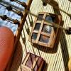
Here are two parts I just sent to Shapeways as samples, to see how they come out. When I get them back, I may have to make changes for the final versions. These are Oyster Dredge Frames for 1/32nd and 1/64th scale Chesapeake Bay Skipjack models. The smaller for the Lindberg kit I'm presently building, and the larger for the MS Willie Bennett, I will start soon.
The upper frame bars on the smaller model, are the minimum 0.3mm wall thickness standard, as is the brace running along the bottom of the 1/32nd frame, from front to back.
-
 thibaultron got a reaction from dgbot in Carrie Price by thibaultron – Lindberg/Pyro – PLASTIC – 1:64 - Small - Skipjack
Part 28
I finally finished the drawings for the dredge frames in 1/32 and 1/64th! I just sent a sample off for printing. I assume I’ll have to make some changes once the sample comes back. The 1/64th model is pushing the 3D printing to the limits of Shapeways standards.
The smaller 1/64th model, had to have some changes, over what I did for the 1/32nd one. The horizontal cross braces were too thin for printing (not sufficiently supported), so I printed the two horizontal bars, too be used as stock for adding them, when I build the frames. I’ll have to fabricate the bottom brace from wire, It was far too thin to print, without being far too large proportionally.
I still have a couple details to add to the 1/64th model, but will wait to see how what I have now turns out. I also added a support/sprue at the nose. The two bars run between the outer skid, and the first dredge tooth on that side. I may have to add a support for the nose of the 1/32nd part. It may help with the printed shape of the part (orientation of the bar to print path). They may lay the part down with the nose on the table for printing, without the support.
I ordered the prints today, and should get them back mid April.
I’m drawing some detail parts to use for cleats, etc., to see if they can be printed. My hands are a lot shakier now, than they were 40 years ago, so making really small parts is difficult, some times.
Now that my shop is somewhat back in order (well at least I can get to the work bench), I can soon start back on the model.
-
 thibaultron got a reaction from Leo-zd in 3D Printing - Not Just Yet!
Here are two parts I just sent to Shapeways as samples, to see how they come out. When I get them back, I may have to make changes for the final versions. These are Oyster Dredge Frames for 1/32nd and 1/64th scale Chesapeake Bay Skipjack models. The smaller for the Lindberg kit I'm presently building, and the larger for the MS Willie Bennett, I will start soon.
The upper frame bars on the smaller model, are the minimum 0.3mm wall thickness standard, as is the brace running along the bottom of the 1/32nd frame, from front to back.
-
thibaultron got a reaction from Leo-zd in 3D Printing - Not Just Yet!
The same material I used for my winch parts.
-
thibaultron reacted to Leo-zd in 3D Printing - Not Just Yet!
Hi, it was printed by Shapeways with material Frosted Ultra Detail because this was the test print, probably the friends will order with Frosted Extreme Detail which have better resolution. anyway the limit is 0,1 mm as the smallest dimension.
-
thibaultron reacted to wefalck in Micro-Edge Sander
Although I recently constructed a micro-grinder and –sander (http://www.maritima-et-mechanika.org/tools/microgrinder/microgrinder.html), I found that some hand-sanding device would be desirable for very delicate operations. Sometimes just a few strokes would be sufficient and the process would be difficult to control with a motor-driven machine. A guided sanding block allows to achieve flat and square edges.
After some rummaging in my collected stocks I found a piece of aluminium rail with a T-slot at one end (I don't remember its original purpose), a piece of thick aluminium sheet, some square aluminium stock, and a well-seasoned piece of pinewood of just the right dimensions (5 cm x 8 cm x 2 cm).
Holes were marked out, drilled and countersunk for the pieces to be screwed down onto the wooden block. The four sides of the wooden block were squared off in the milling machine with the aluminium pieces in place. The wooden block then was carefully levelled in the machine-vise and a slot milled into the aluminium as a guide for the sanding block. Finally the surface was evened with some light cuts with a fly-cutter.
A mitre-guide was fashioned from a piece of flat steel. It can be mounted left or right and in different configurations.
The sanding block is fashioned from some 8 mm x 8 mm square aluminium stock. It has shallow recesses milled into both sides to allow for the thickness of the sanding paper. A knurled screw M3 serves as handle. to begin with a glued a strip of 600 grit wet-'n'-dry paper onto one side and a strip of plastic coated with abrasives as used by dentists for grinding and polishing teeth onto the other side.
-
thibaultron reacted to Phill Elston in WW1 German Destroyers "found"...
http://www.shipmatesreunited.com/german-wwi-warships-rediscovered-in-portsmouth-harbour-after-lying-forgotten-for-decades/ -
thibaultron got a reaction from Leo-zd in 3D Printing - Not Just Yet!
What printer/service did you use? Nice clean prints!