HOLIDAY DONATION DRIVE - SUPPORT MSW - DO YOUR PART TO KEEP THIS GREAT FORUM GOING! (Only 75 donations so far out of 49,000 members - C'mon guys!)
×

Mark Pearse
-
Posts
830 -
Joined
-
Last visited
Content Type
Profiles
Forums
Gallery
Events
Everything posted by Mark Pearse
-
 Hi Jim She's a very goof looking ship, her lines are lovely & I hadn't appreciated that earlier. Now that the masts & rigging are coming together it's more visible.
 -
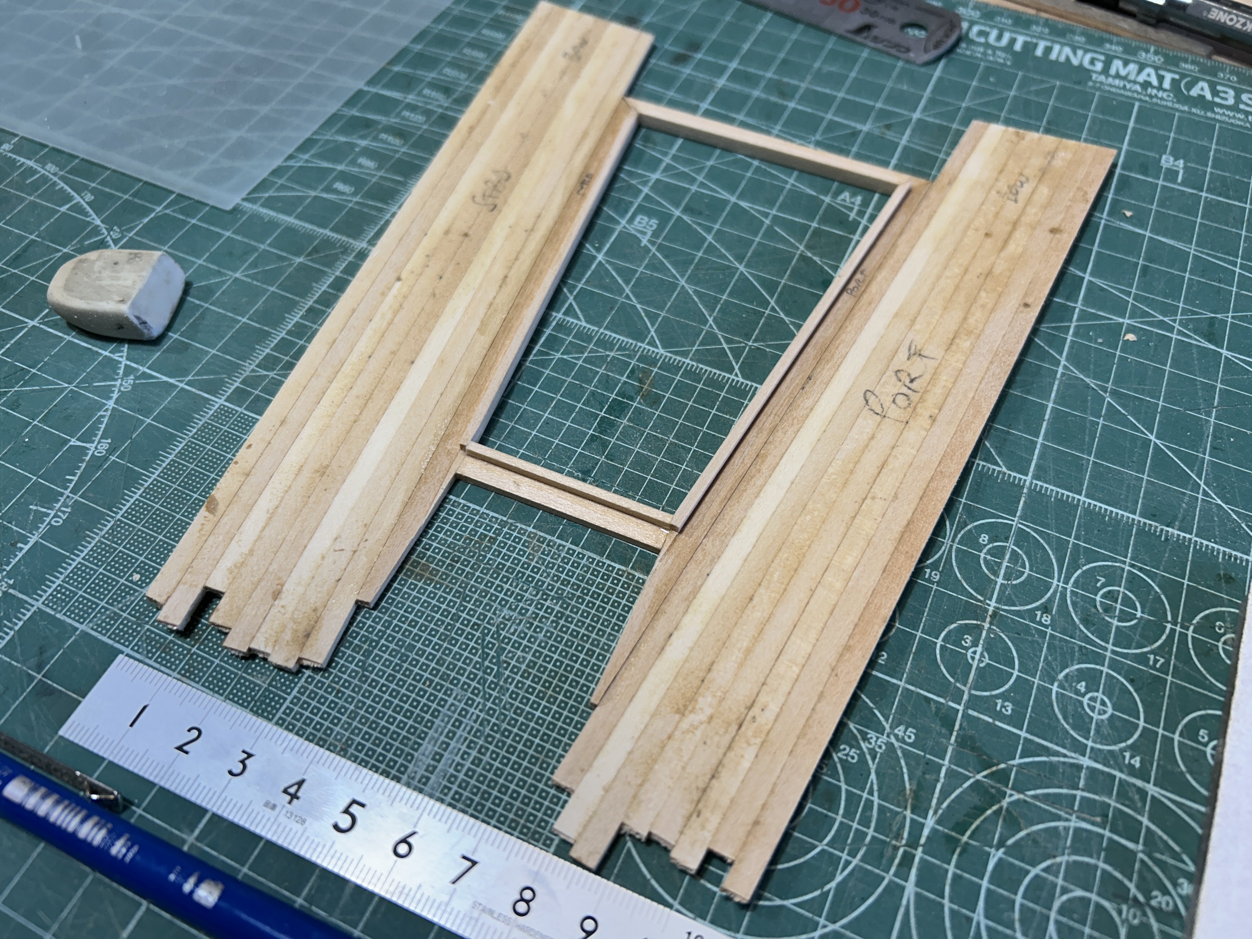
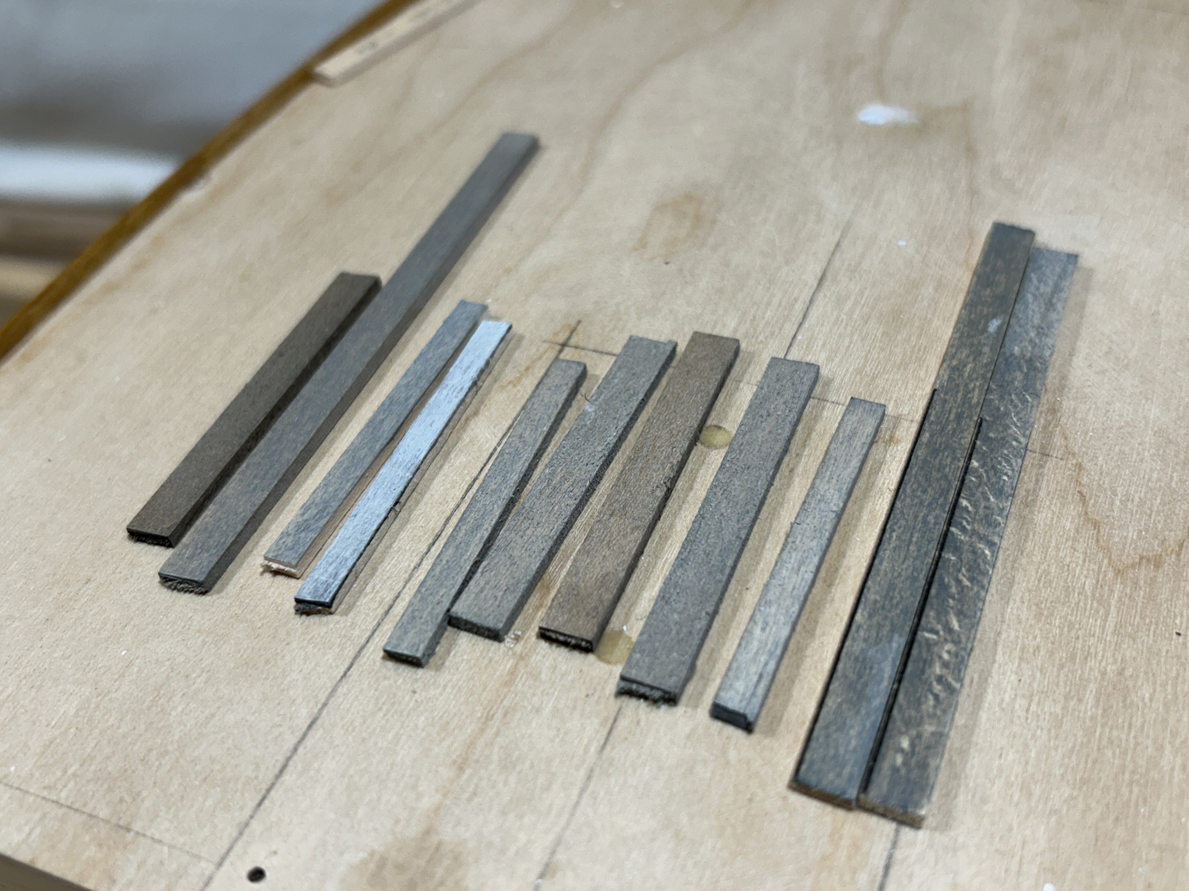
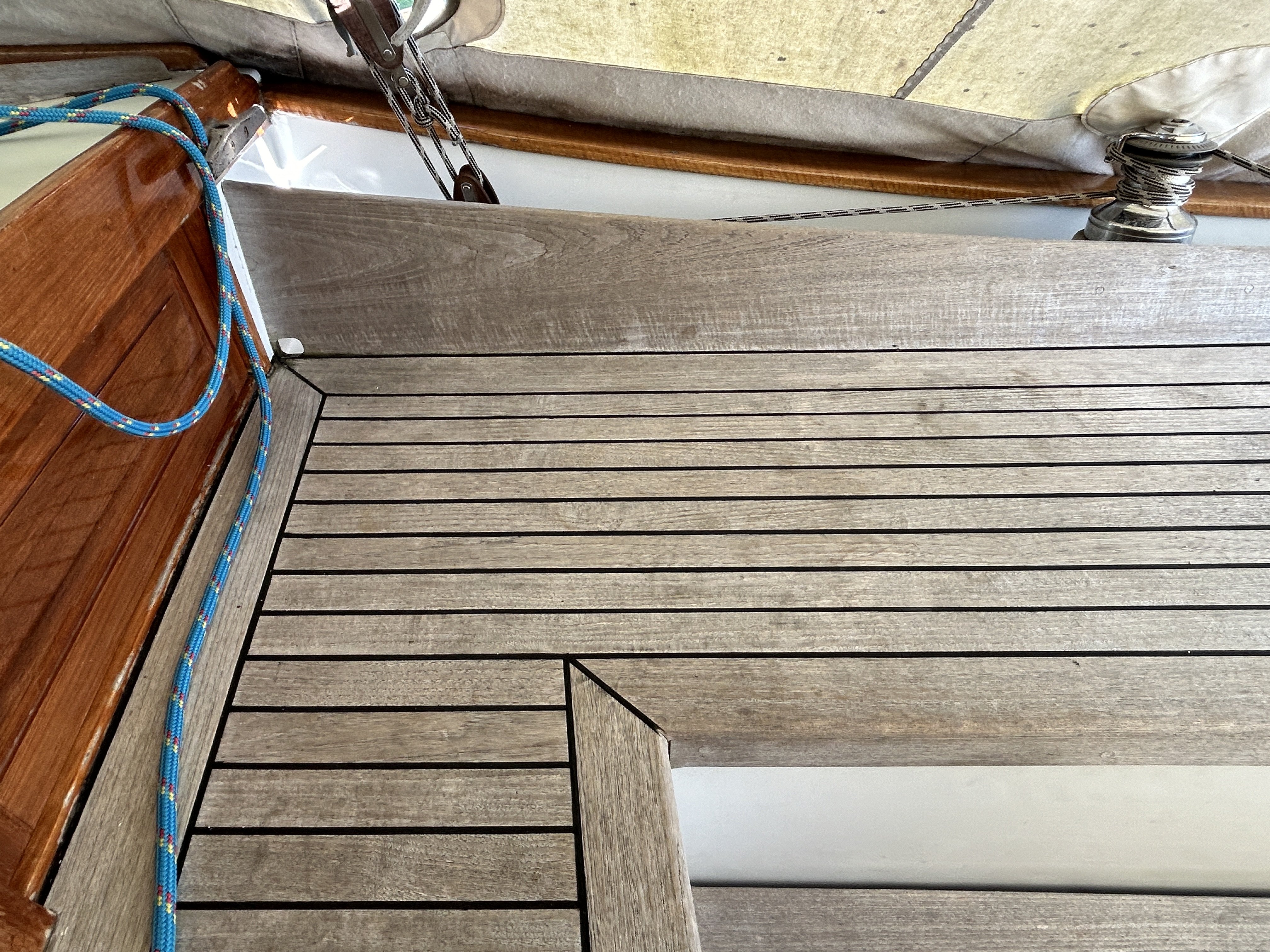
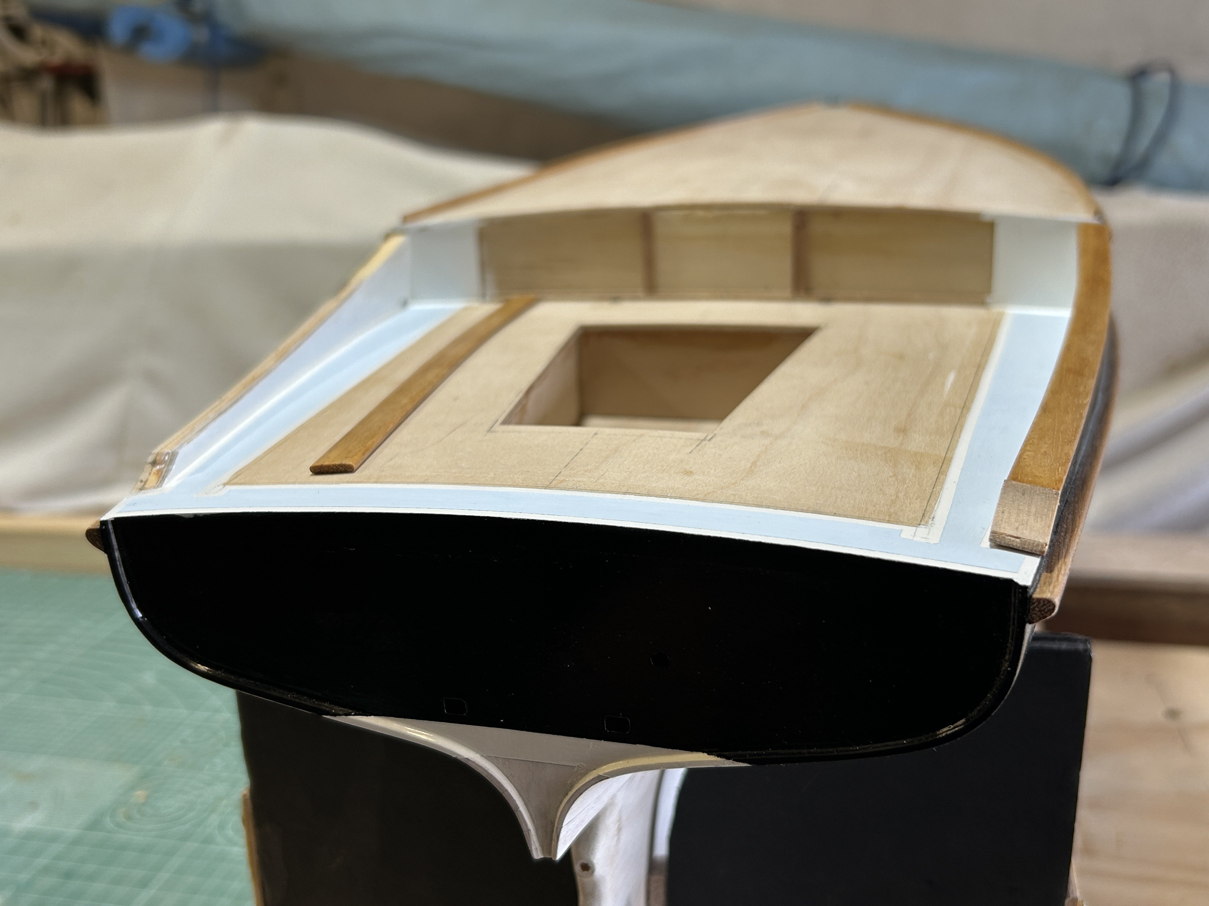
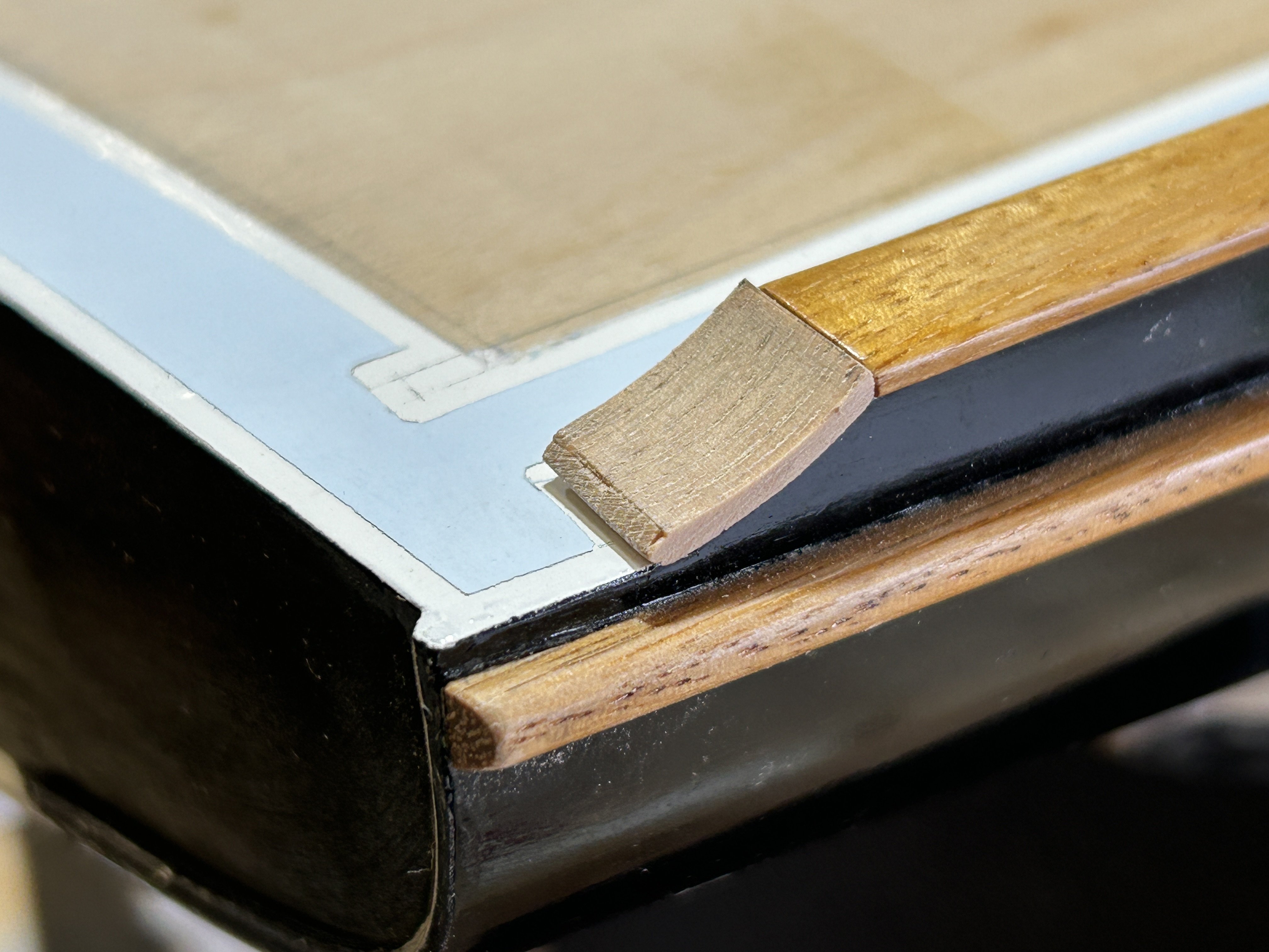
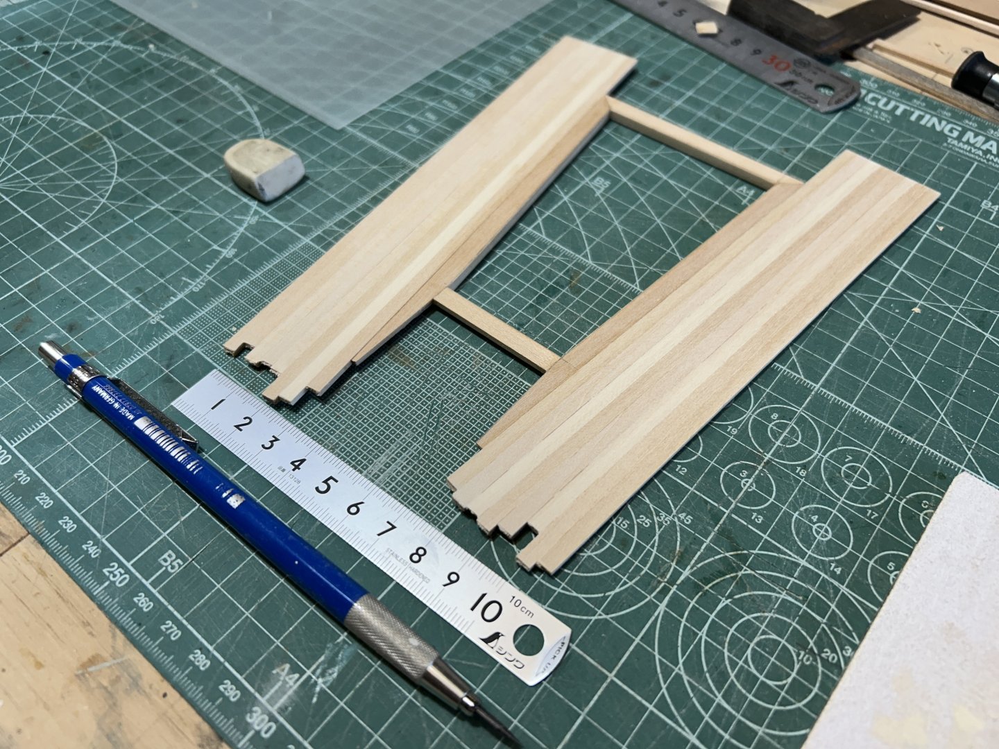
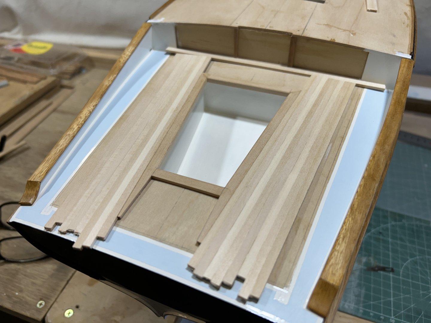
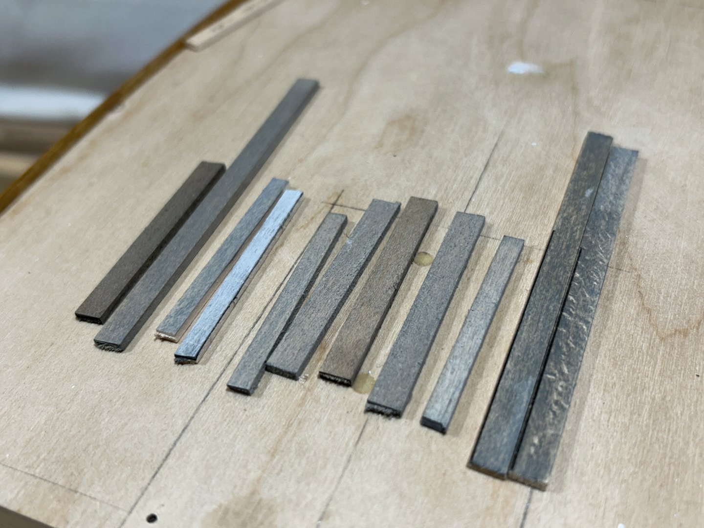
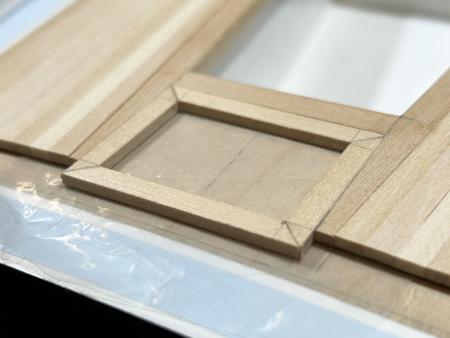
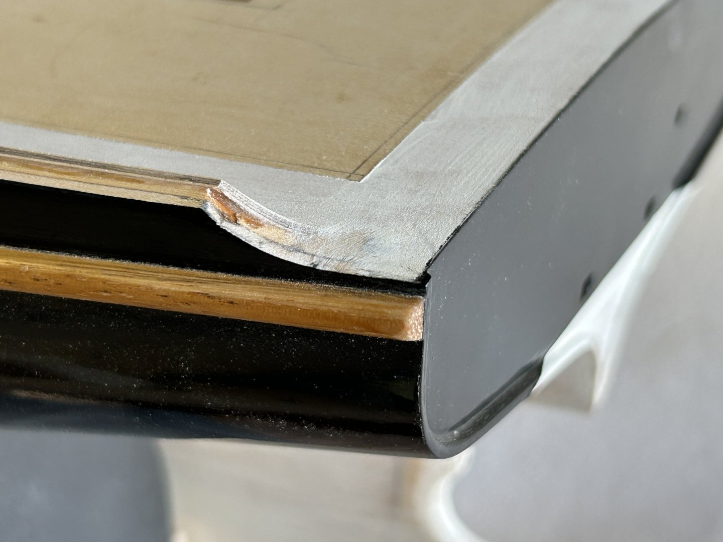
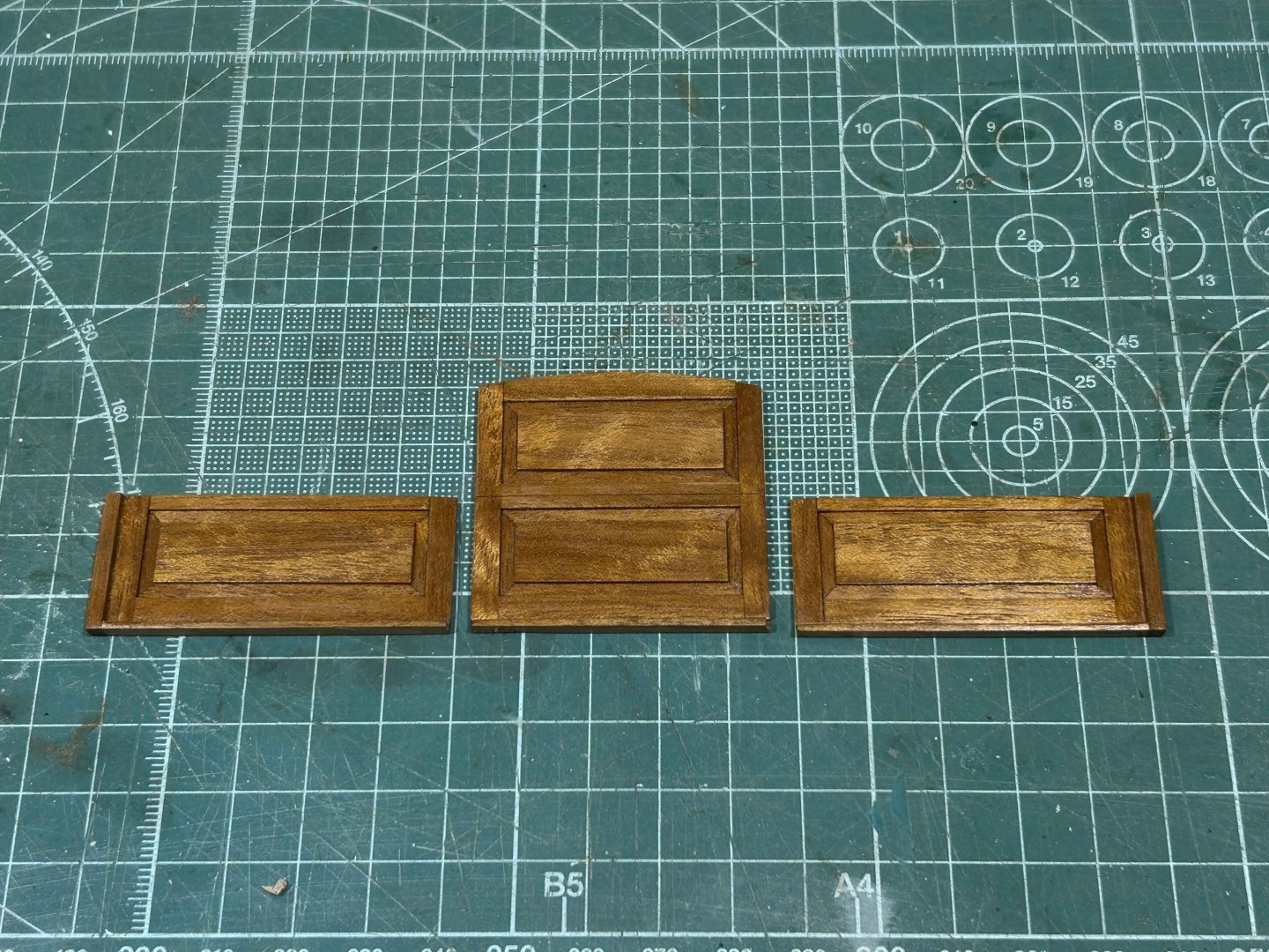
thank you all, I've started on the cockpit seating & some other details that on the actual boat are unfinished teak, ie: greyed from natural weathering. I was dreading this work, it's got a lot of detail & also getting the weathering right. A few weeks ago I started researching weathering techniques on this forum & the web generally, some techniques are fairly simple but for one reason or another I remained unconvinced that it would be straightforward. The tests I did included rough sanding & scuffing the surface of the timber; dipping in diluted black paint, then with white added, then with beige added; wiping the surface of the timber strips with undiluted paints, diluted paints, on scuffed surfaces....The good news is that the most simple of the techniques seemed to work the best - essentially just wiping unscuffed timber with black or grey undiluted paint. Now that I was confident there could be a reasonable result I started working on the cockpit seating. The technique was to build it on the model, but not yet gluing it on. The loose strip at the forwards edge is a border strip, to be fitted later. And from the underside, you can see the downturned edge to the cockpit footwell, the edge piece is an L for the visible edge thickness: And the lazarette hatch underway. You can see a piece of plain plastic sheet underneath, that's how I've been able to glue in situ. I think it's easier to make something accurately to size when you're building off assembled pieces rather than guessing from loose pieces. A shot of the actual cockpit, when you look carefully the colour still has some natural warmth, it's not a pure grey. Below that are some of the weathering samples. Most of them are too heavy & too dark. Most also obscure too much of the timber colour, the best ones allow that natural colour through a bit. The single strip 2nd from the right is getting close, needs a little more tweaking but I'm happy that I can do something satisfactory. The caulking will be done with an artist grade 0.5mm ink felt tip pen.


-
Hi Vaddoc Looks good, & I wish my work space was half as orderly as that. Out of curiosity, are you reinforcing the plank joins? Butt blocks on a yacht....
-
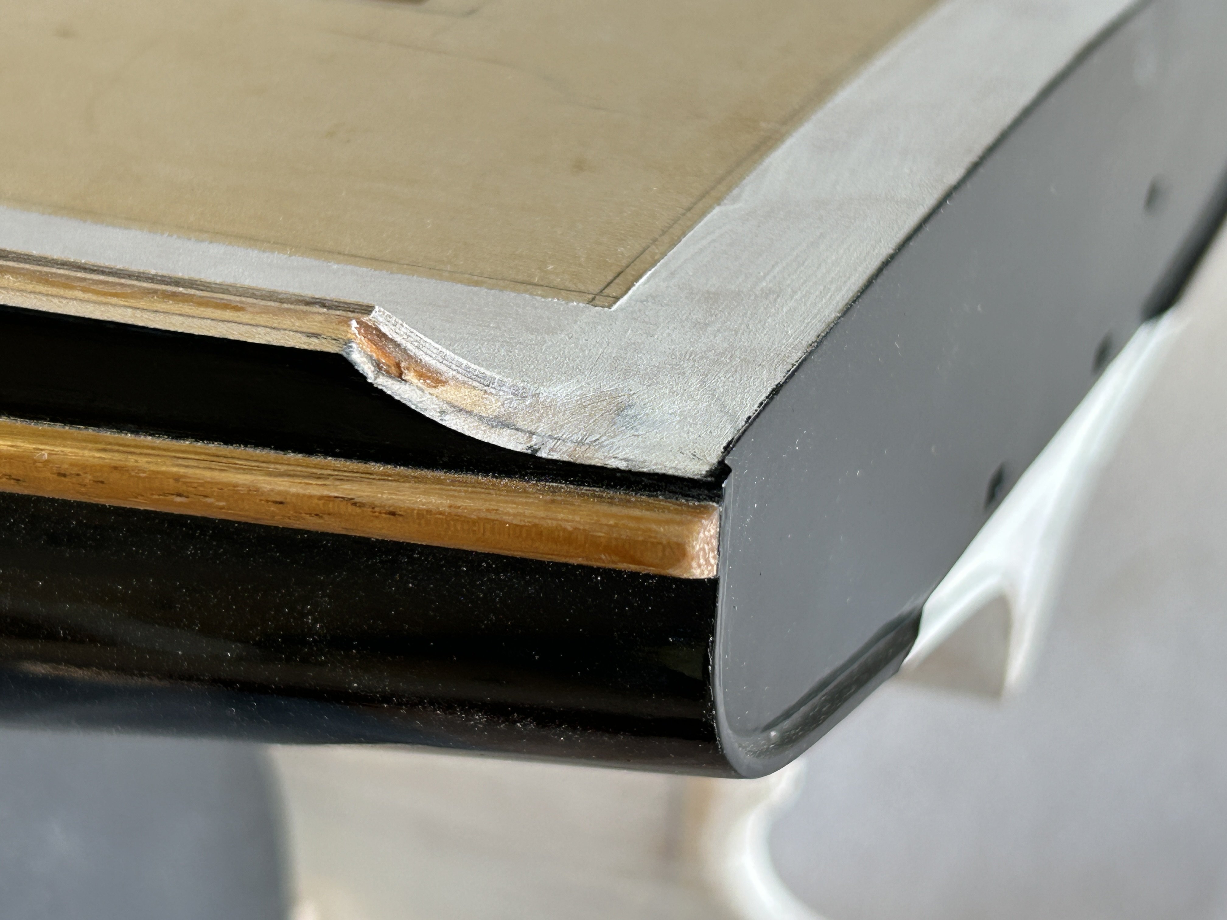
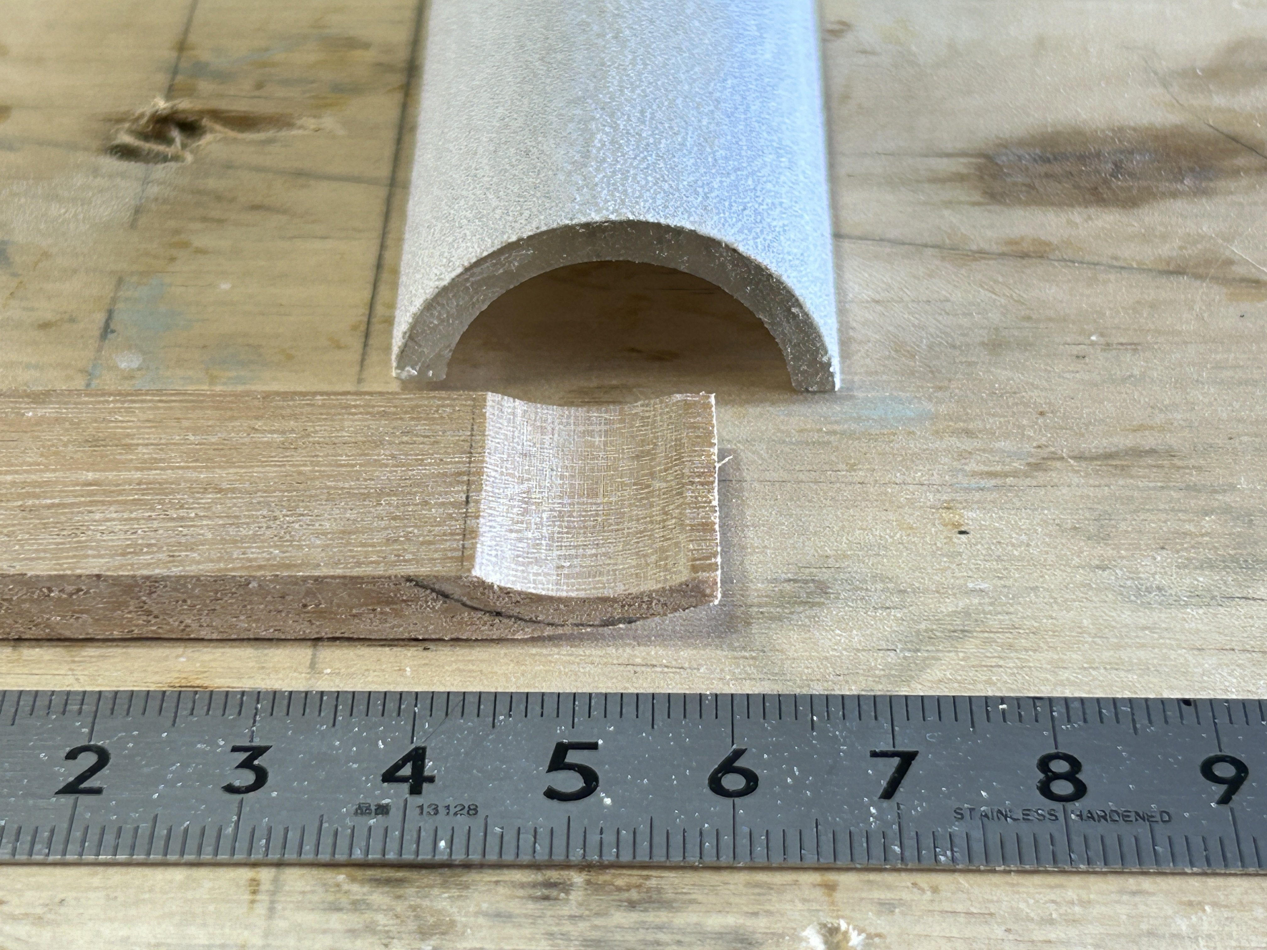
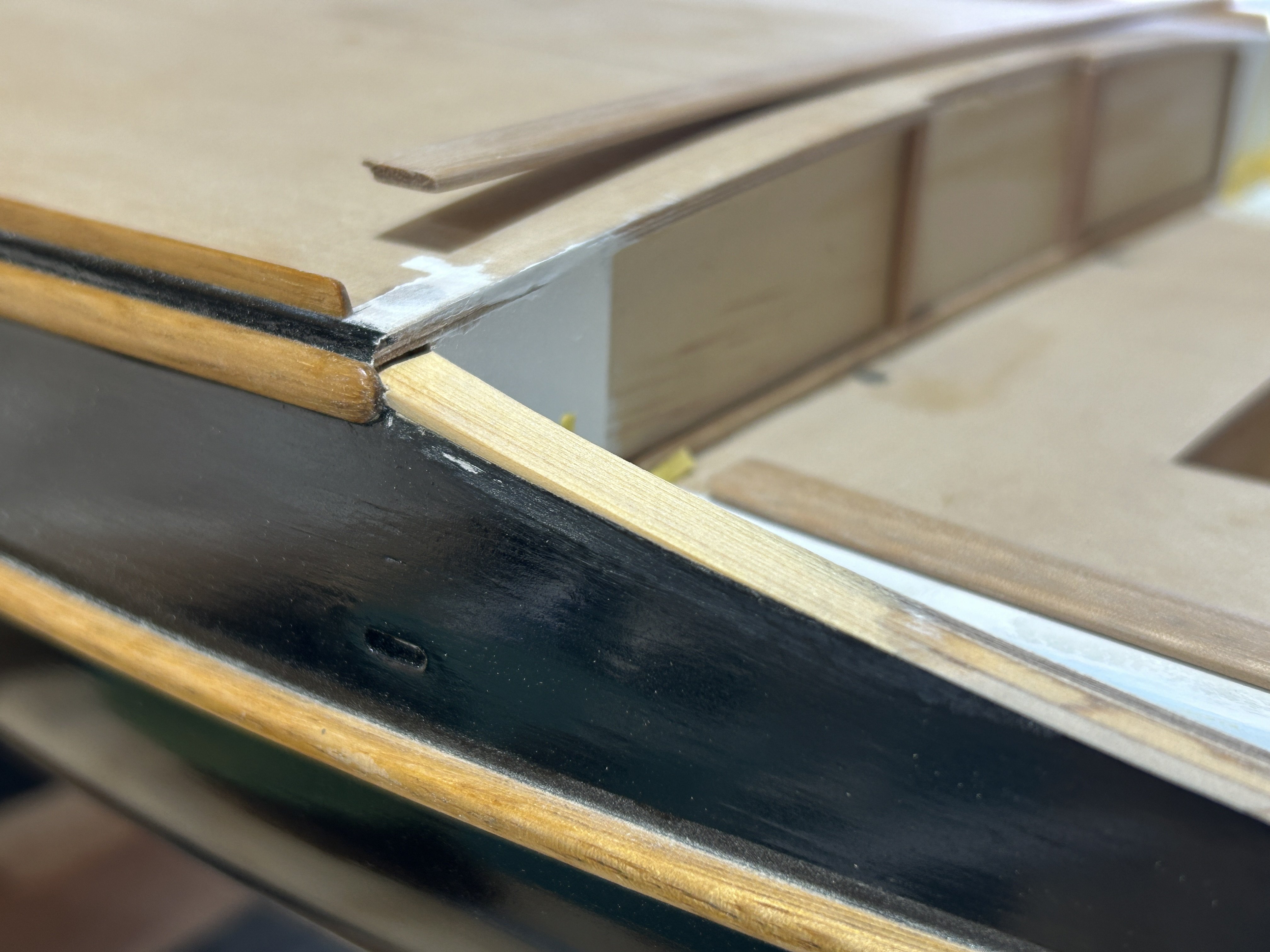
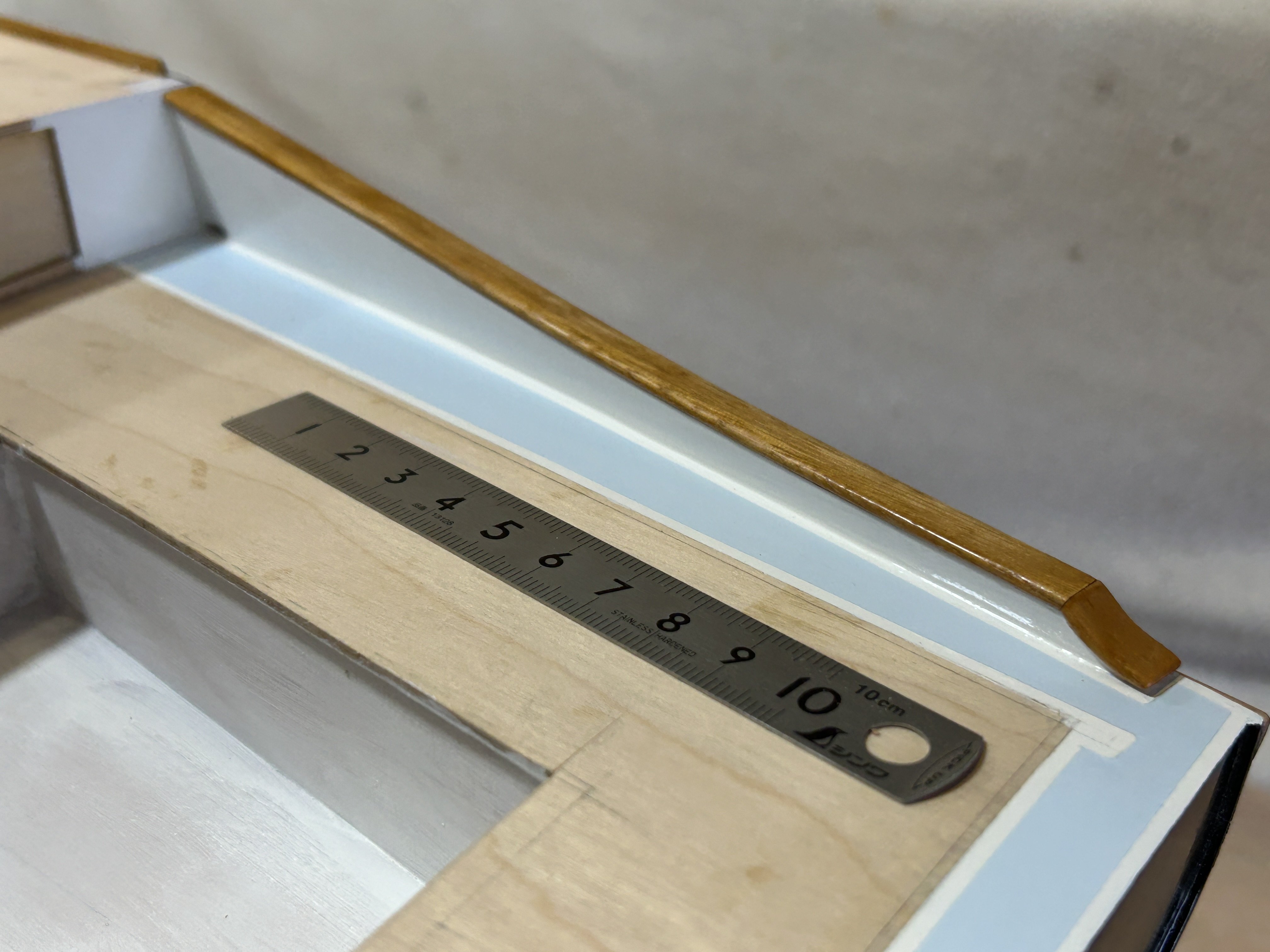
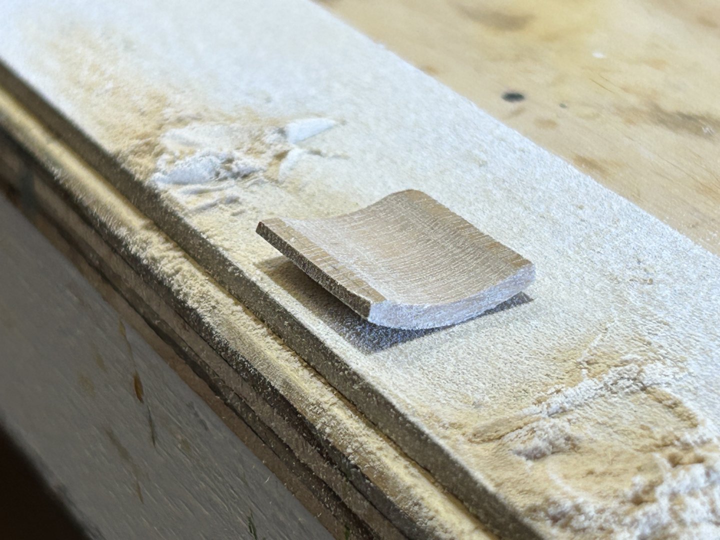
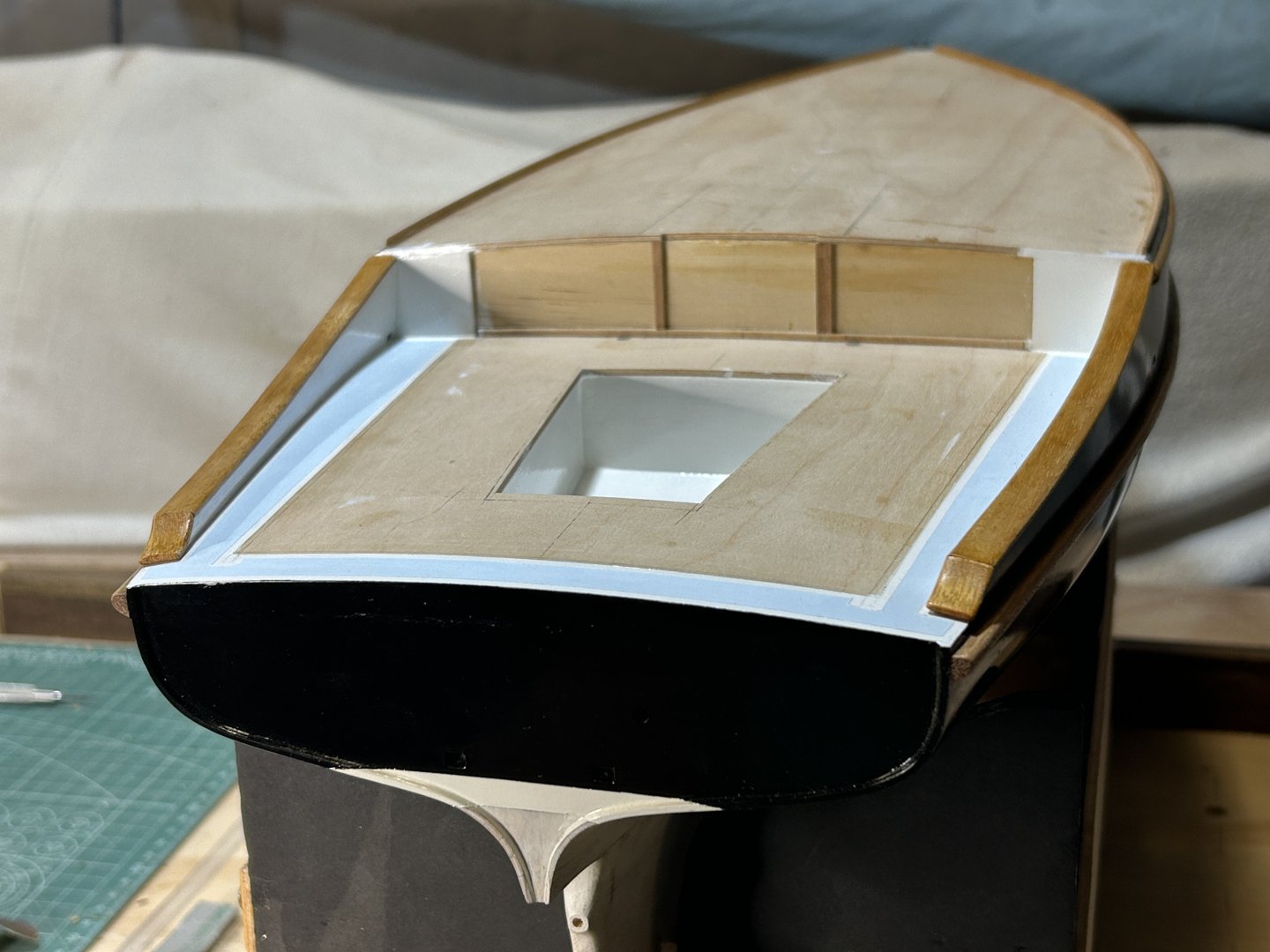
I haven't posted for a while, but I'm back working on the model. The sailing trip in Tassie is posted in another part of this forum, linked below if you're interested. Back to the model, I've been working on the cockpit area, starting with the toe rails, just visible on the upper deck forwards of the cockpit. The toe rails were delicate, about 1.5 x 2.5mm & maybe 300mm long. Then the timber strips that visually complete the hull step-down alongside the cockpit. The timber is Blackbutt, from the same floorboard offcut I used for the gunwales & sponsons. Then the small cupped strip aft of the previous photo, to fit in this curve: I had a piece of round acrylic tube about the right diameter: Then some more sanding: I picked up an error in that strip of side decks, on one side I'd clearly been daydreaming while sanding....so I added on a filler piece of timber, then undercoat, paint etc.: I painted the two-tone deck (or scuppers area) around the cockpit seating. On the yacht it's painted in a more modern style, where there's an edge strip with the deck paint set in, & in different colours. Tamiya have masking tape in 2mm width, which helped get a constant gap, plus some 6mm masking tape to help stop overpainting onto the adjoining finished paint. Then glueing the timber strips on - as per the previous timber, I really prefer shellac for scale varnish, the thin viscosity helps the finish to look right at scale. Not to say you can't get other finishes to look right at scale, but this works for me & it dries quickly...& I like the way you can matt it with steel wool & gradually buff it back to satin with some cotton rag. Then carefully fitting the little curved pieces... And one side done. Then both. Some details fixes will be required to the paint, but I'll do that all in one go later. The deck will get painted soon, so I started shellacking the cockpit stormboards, made earlier. I'll paint the deck next I think, then start on the weathered teak cockpit seats & other details. Thanks everyone


-
Hi Vaddoc, If it is a print that you are talking about, one possible reason for a small error is that some printers slightly shrink to fit the page, without telling you. If you drafted in CAD to a certain size virtual page (eg A3), then when you print, you print to A3 paper size, but the virtual A3 is slightly reduced by the edge margin of the paper that the printer can't print on. The solution is to find the option in the print dialogue window that allows you to set the printing to 100% scale.
-
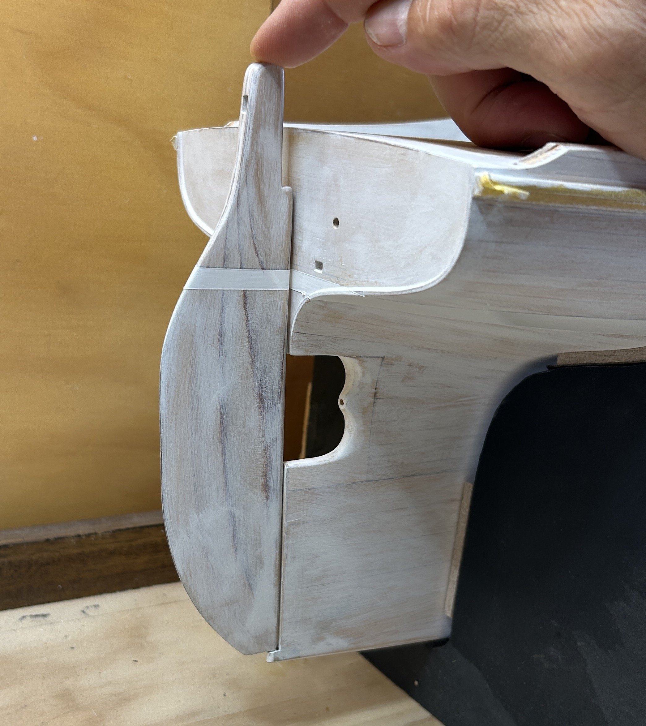
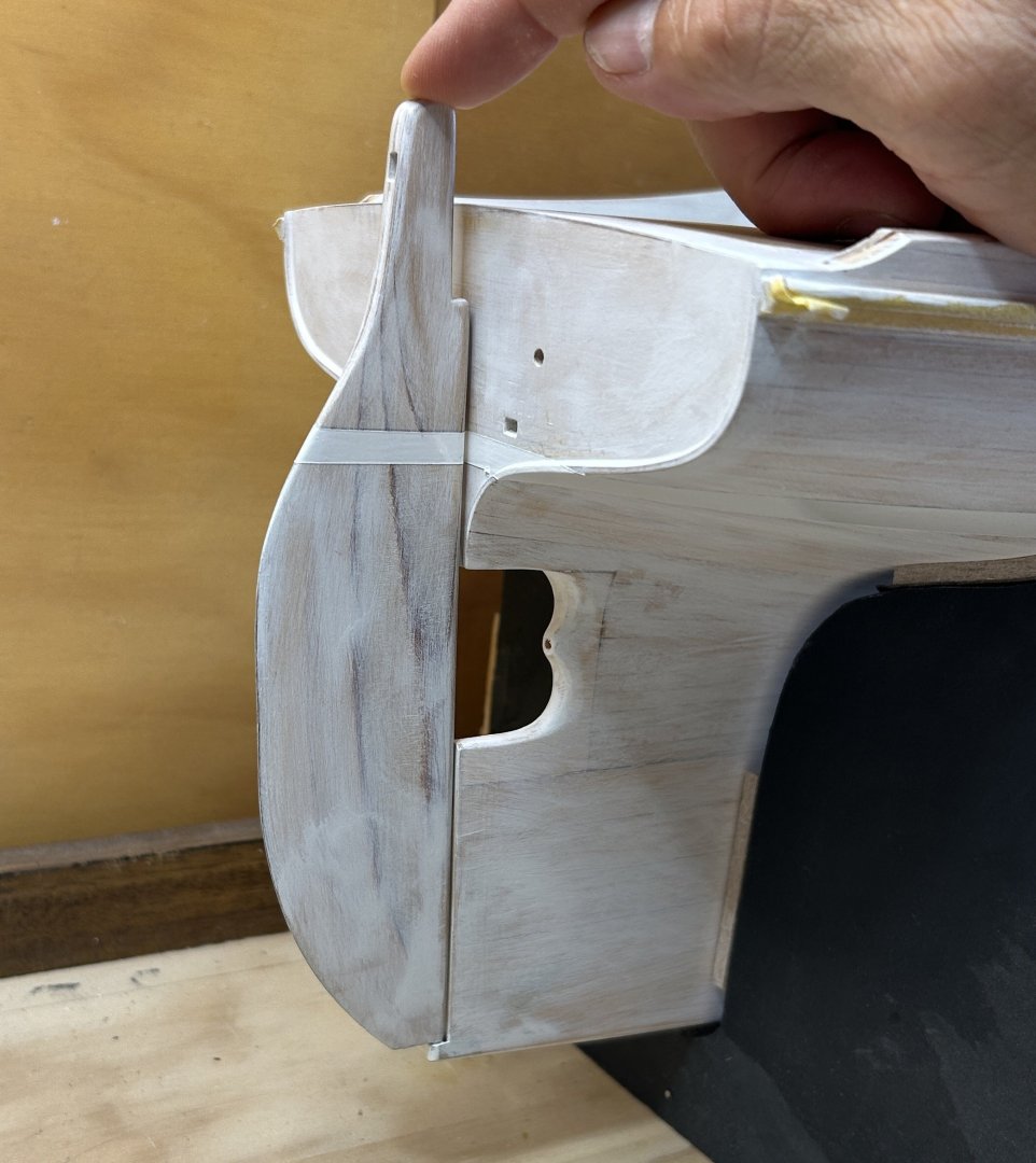
Hi Steven Some responses from the gallery: In modern traditionally built yachts: yes, definitely. The planks ends are then housed which gives you a backed recess into which to bang the caulking, pitch, putty etc. it's a really important joint. And if the stern post is hit heavily by anything (such as a dock), the impact load is somewhat transferred to the planking & on to the hull at large, instead of pushing the stern post only. To my simplistic thinking it's logical they would have rounded it. But it would be easy to have it square & not foul anything - it's just a question of where the pivot point is, closer to hull or further away.
-
Thanks Steve, the first legs are quite exposed to the south & SE, & of course the weather changes pretty quickly down there. I'll post some photos on return.
-
Your exploration of the hull via CAD was very interesting, & CAD drawings are useful in understanding the object drawn. Like you, I also used CAD to get an initial idea of the planking angles where they meet the keel, stem etc.
-
thanks John, my trip - but who knows, I might bump into Trevor
-
Hi Trevor That sounds like an amazing trip. The weather changes more rapidly in Tassie than in NSW, & I'd rather keep the wind below 20 knots ..... IF HUEY IS LISTENING.....
-
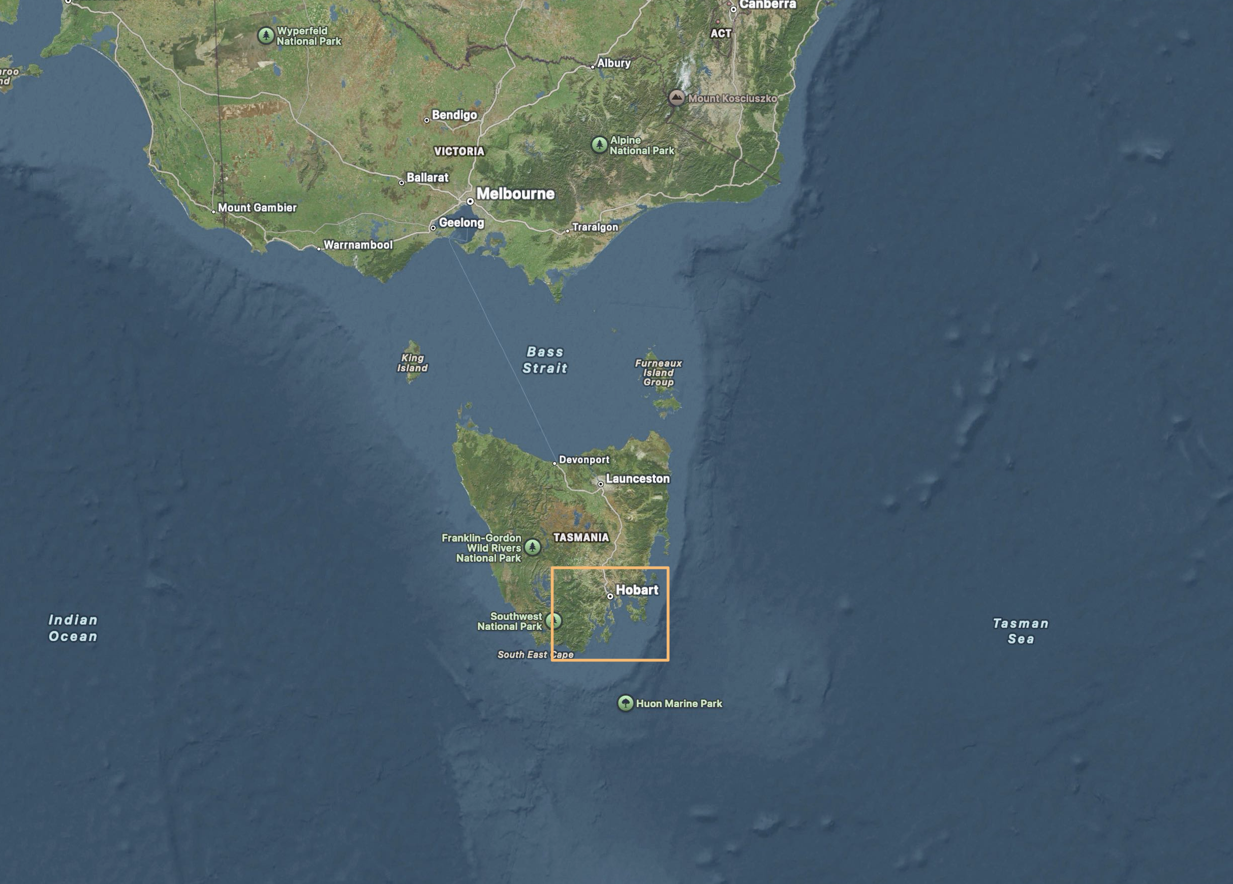
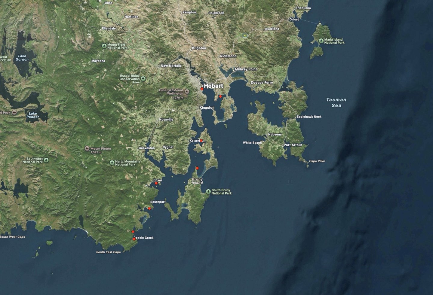
We're all boat trajics here, so I doubt anyone will mind if I go off-topic, on my own blog: I'll be away for a few weeks, happily going to the Wooden Boat festival at Hobart. But, even more exciting, I'm sailing on a small boat raid for 10 days leading up to the festival. The red dots are the intended stops, starting down the bottom. For context, the detail map is the orange rectangle on the other one. The first few days are obvious exposed to the south & south-east. But assuming the weather is ok, it should be really good, some wonderful country there.

-
Hi Vaddoc, Good progress, & this is something of a departure for you - most of your builds have been for smaller planked sailing vessels. I look forwards to seeing how this unfolds,
-
Hi Dick Have you been using local hardwoods, & how do you find them to work with? Some of the timber looks to me like Jarrah or Karri, both seriously dense & hard wood.
-
Best wishes Håkan The mast is lovely timber - what species is that?
-
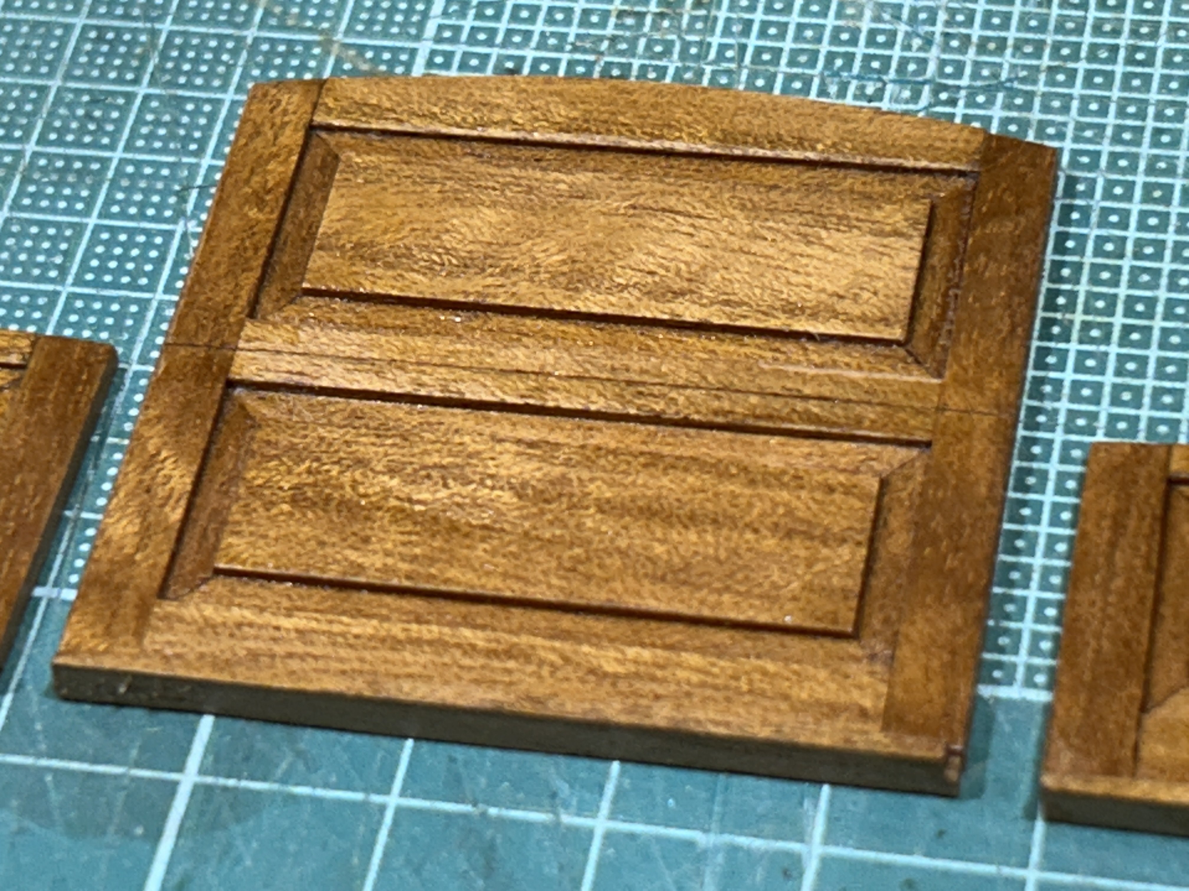
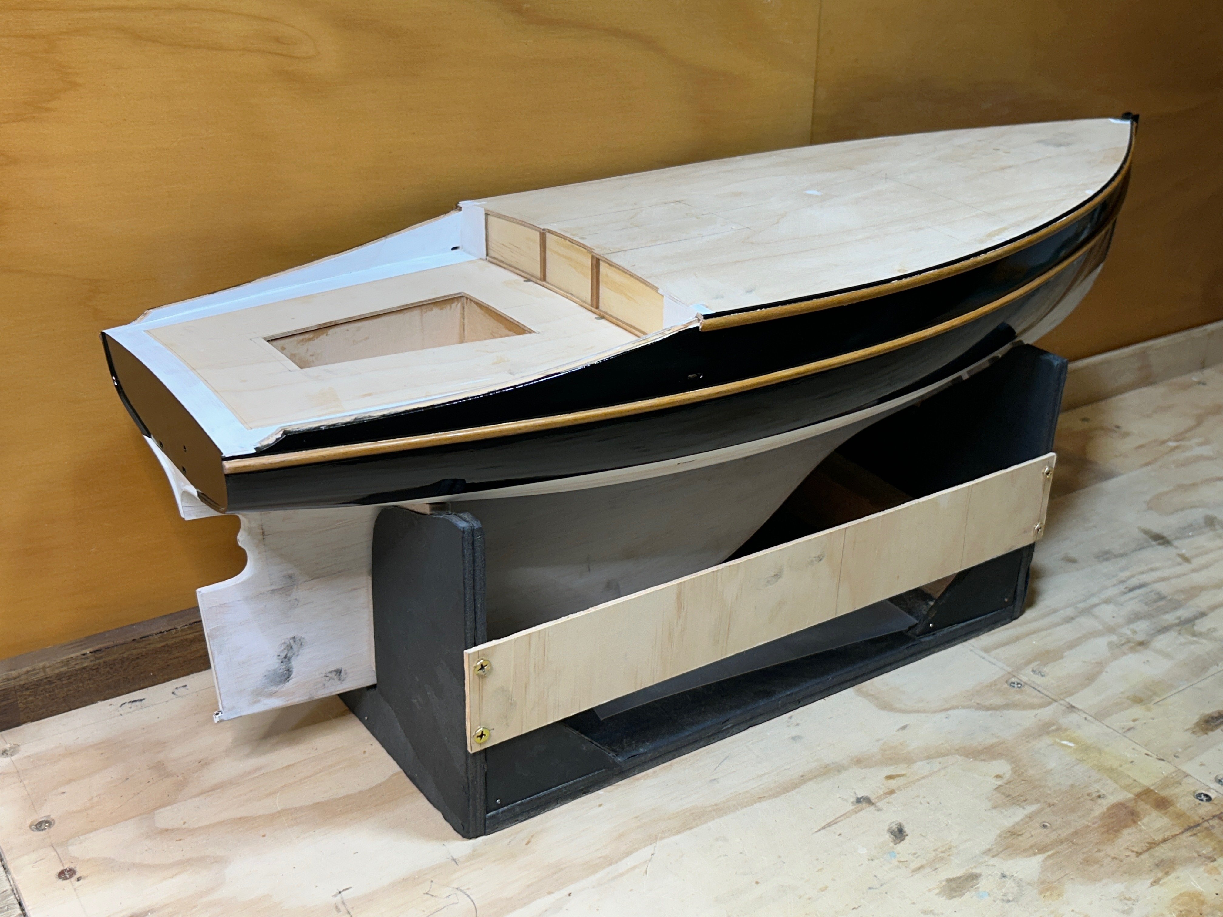
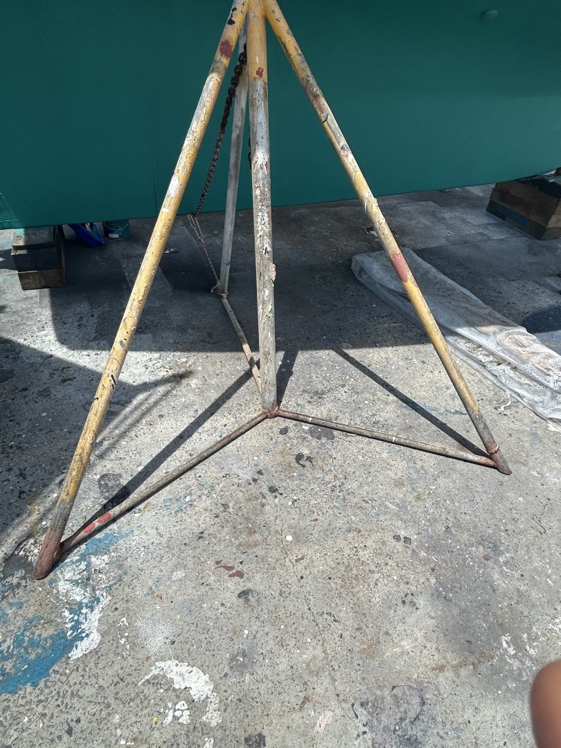
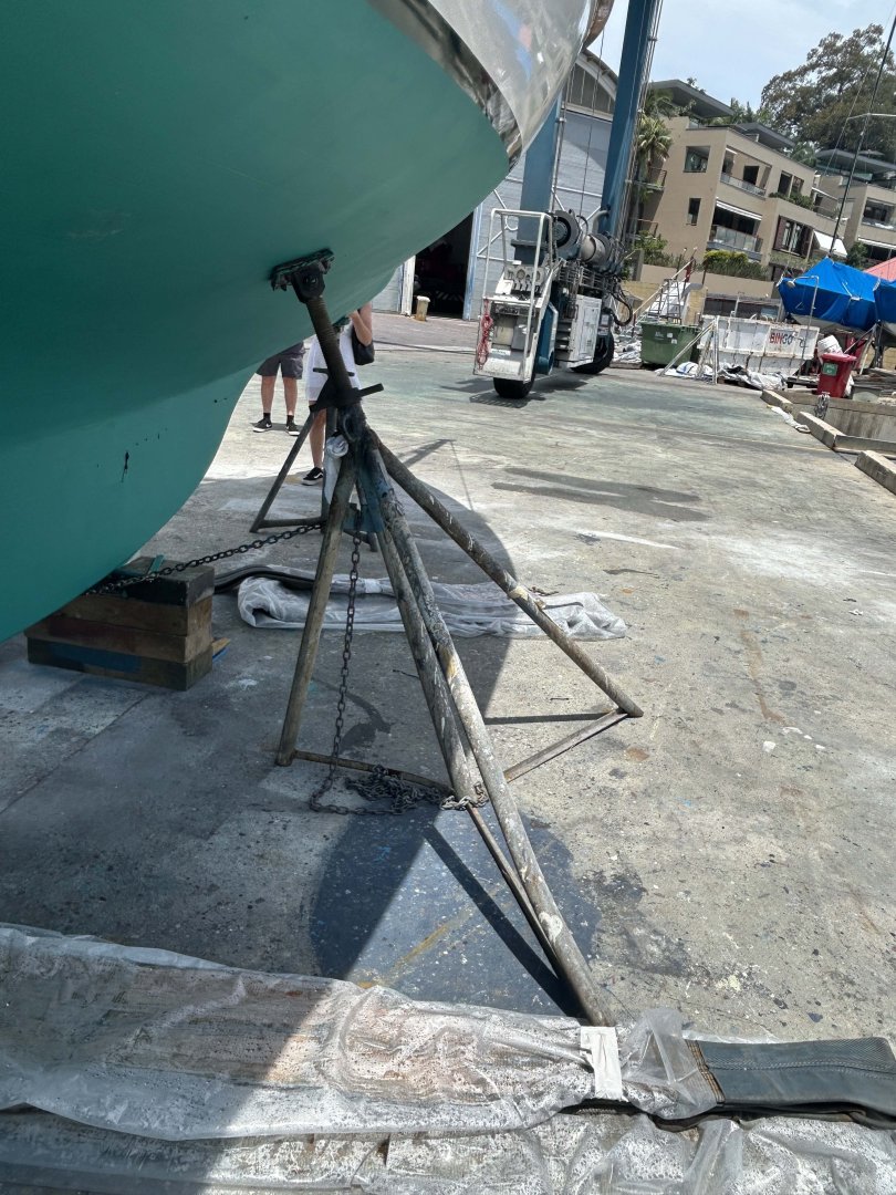
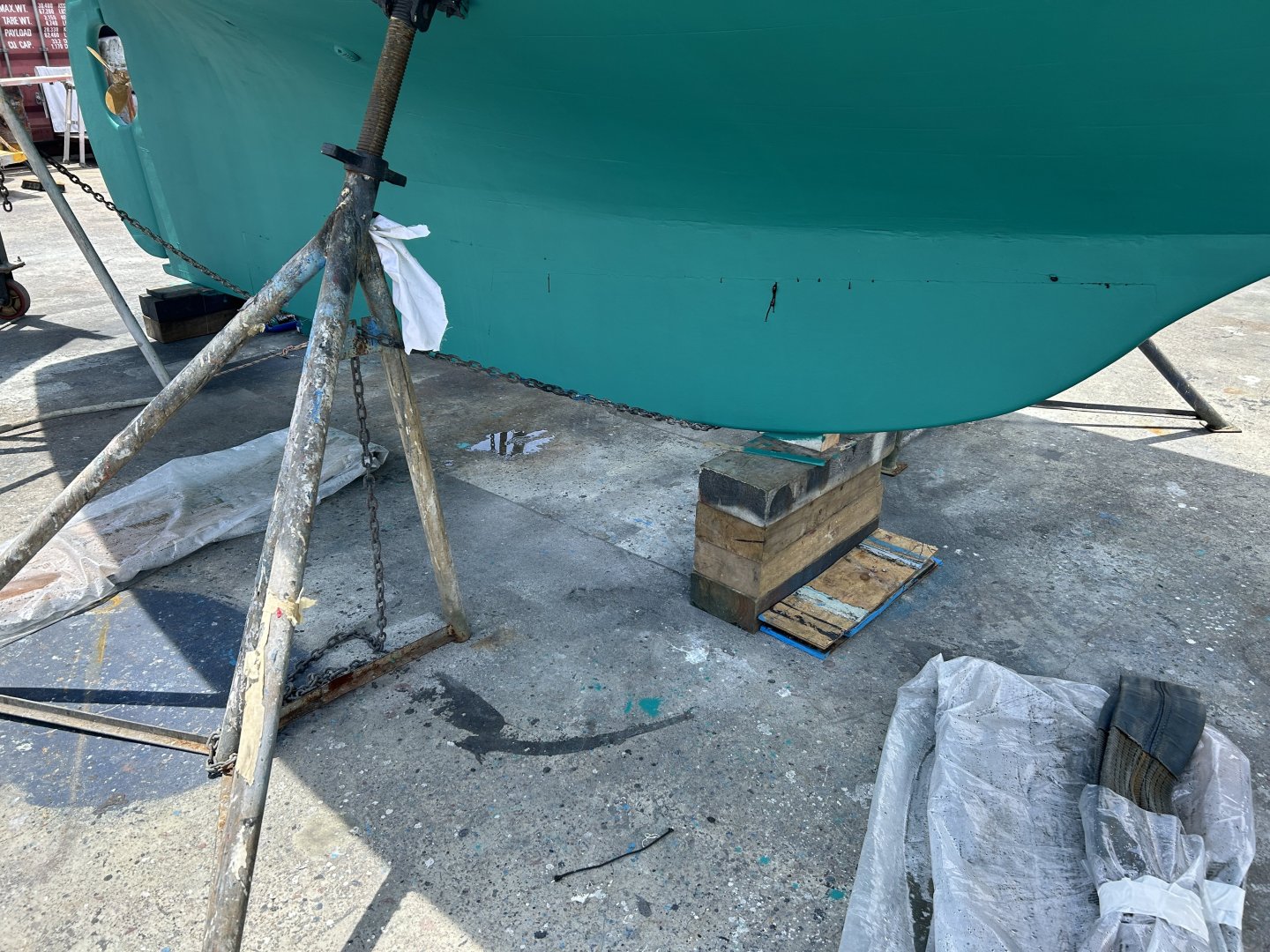
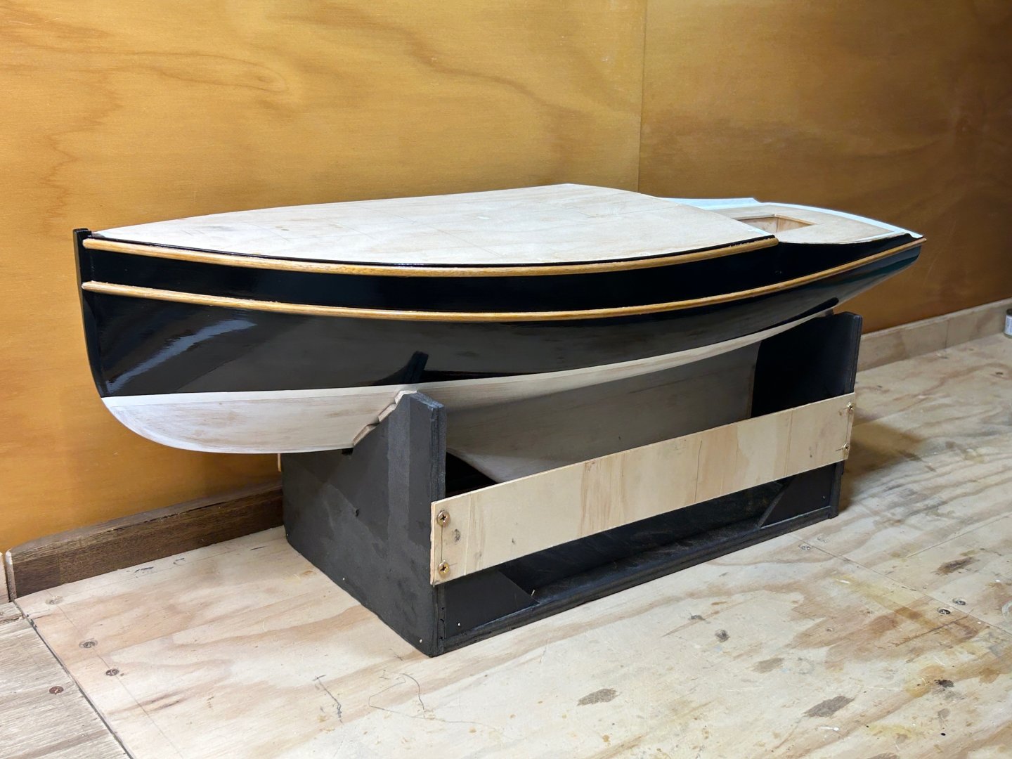
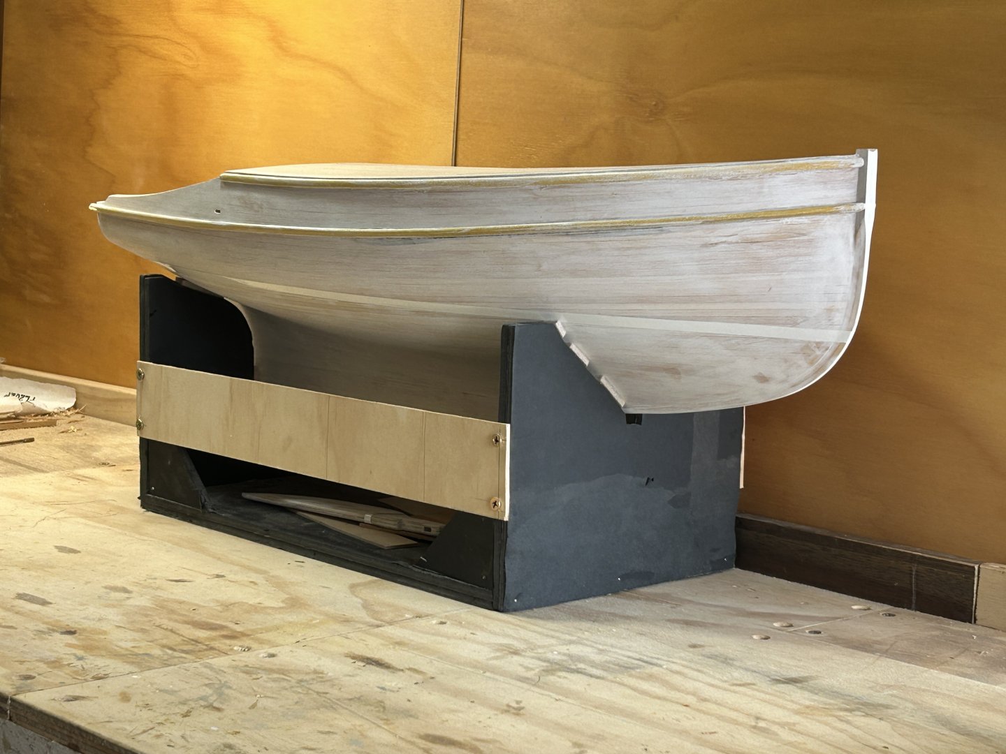
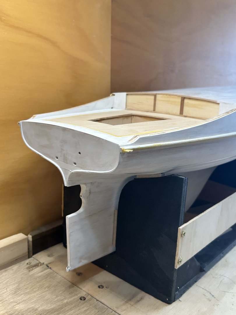
Thank you Roel, & I like the colours too. I'm doing a model of a specific boat that has these colours, so the timber choice in the case was to replicate the timber on the original, but it does go very nicely with black. One aspect I'm thinking about is the stand. I've decided to do a flat rectangular base that replicates a boat yard hard-stand area....spilt paint, etc, & the model held up with scaled support frames, some photos below. Maybe a piece of thick compressed fibre cement sheet as a base....
-
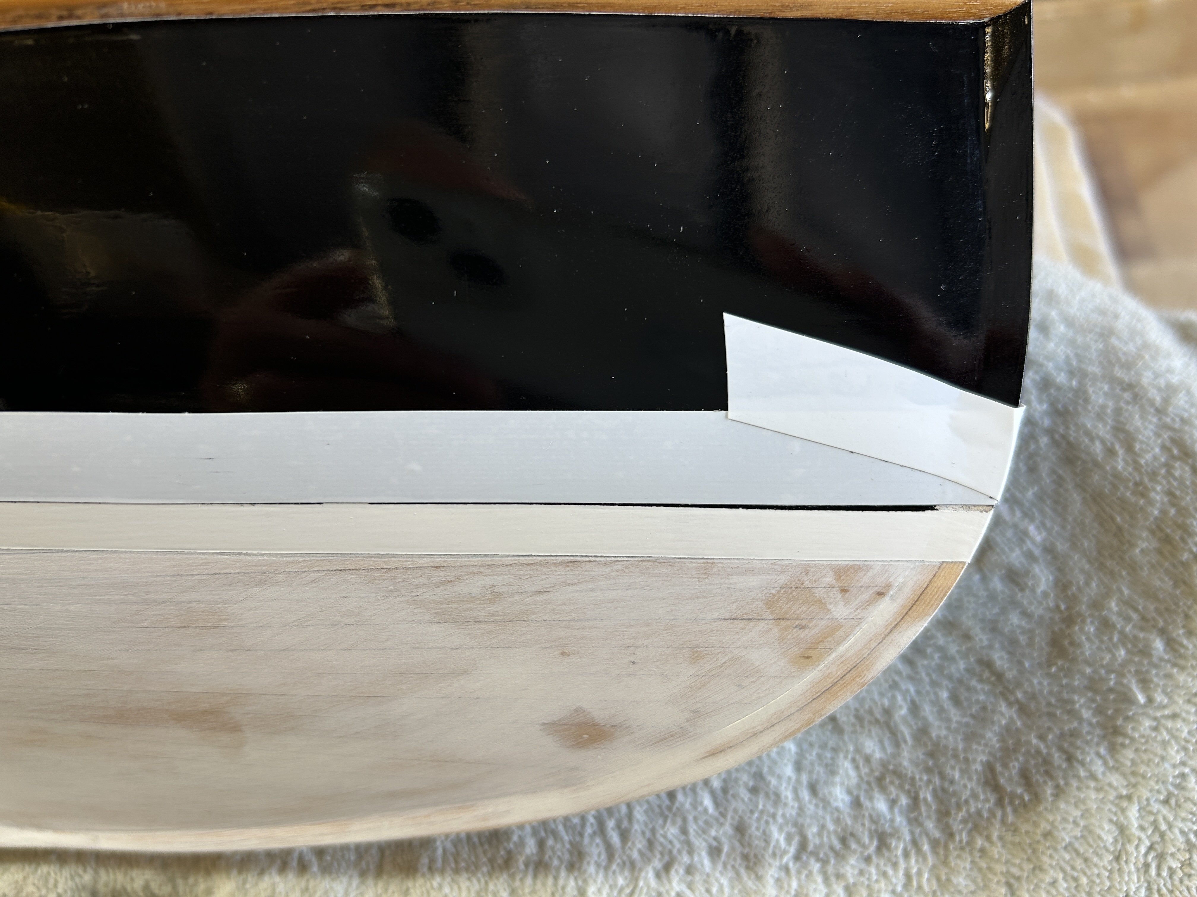
Almost like bought one....it looks like the top edge of the boot top line didn't have quite enough lift towards the bow, just the last part. I usually find that going back & adjusting something is less work than I expected, so I jumped in & started it. I scratched the black paint off, after carefully cutting against the side of the masking tape to give a sharp line to scratch off up to. Will undercoat, sand, topcoat, sand etc etc. A bit like the Spam song....

-
Bravo Vaddoc, a great result. I'd better start following the Hercules build....
-
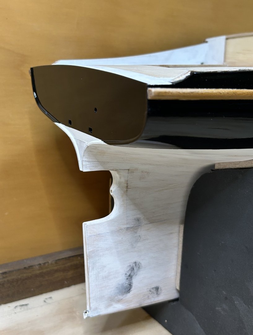
Thanks everyone. And no longer a whiter shade of pale.... I'll give the Humbrol paint a few days to harden, but it seems less hard than previously. The unmasking went ok, quite a few small tears, even though I sanded everything between coats. I'll need to work on them, one tiny spot at a time. The paint mix ended up about 20-25% satin & the rest gloss, with a few drops of Penetrol. Black is quite unforgiving, it shows flaws more than paler colours. But I'm pretty happy with the most recent coat & I'll have a good look over the next few days.. The transom may need another coat, as the flatness is even more unforgiving than curved black.


-
Hi Wefalck, good points, I've never done it myself so I'm not sure - but they try to dive away from the boats when trouble is coming.
-
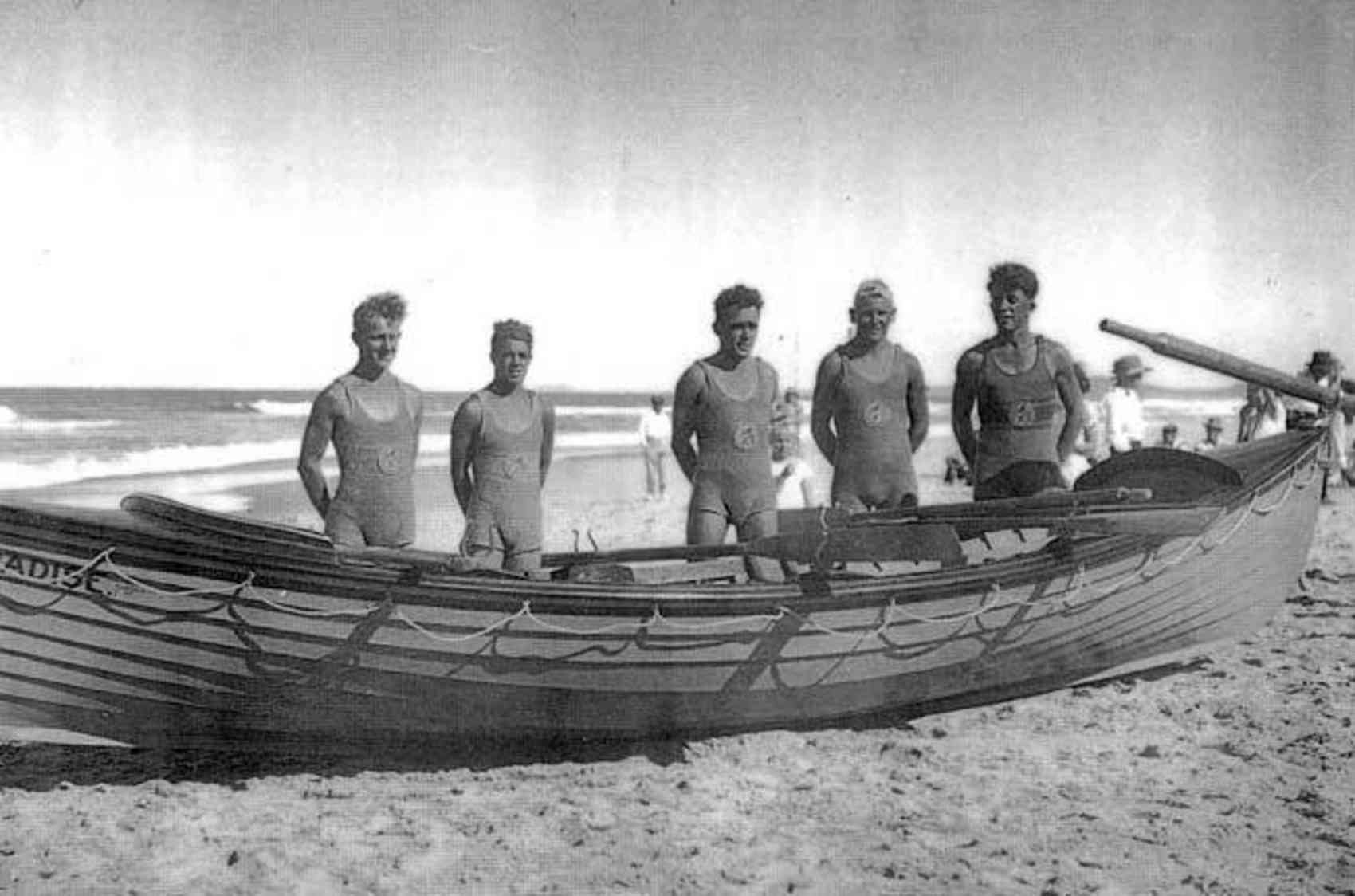
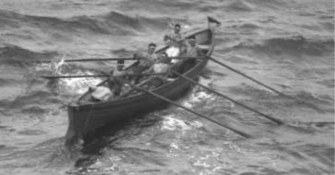
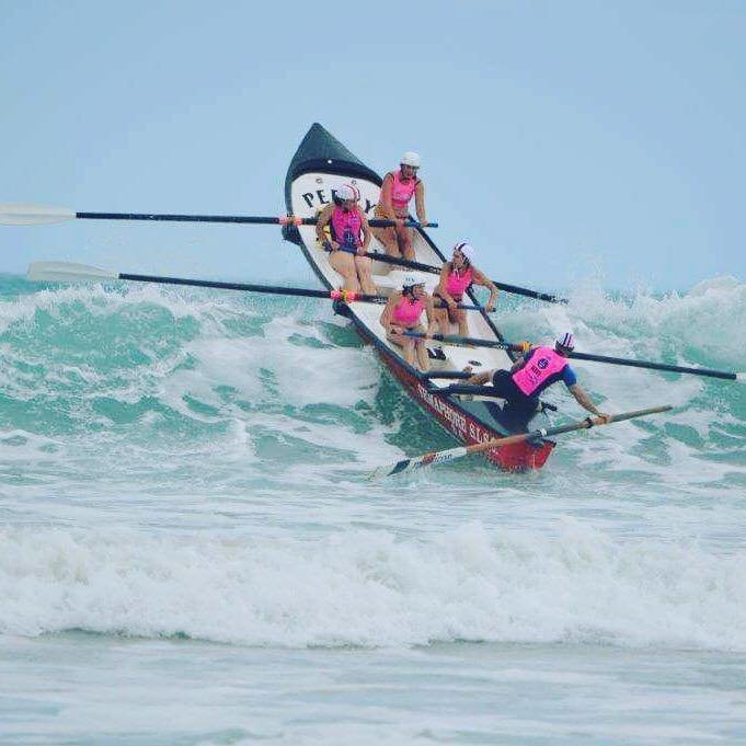
That's great to see the interest, I think they are very special craft & a very special sport. Hi Mark - she's with Coogee. It's one of the nearby alternatives & actually not great as there's not really surf there, but when there is swell it's nasty large dumpers on the sand. Yes, certainly the cold-moulded ones are nicer, but it's interesting the latest are not much different in shape - Hi Rick, not sure but the major surf club meets are a big deal & televised. The boats are just one of the sports. yes the surf is good for that I found some photos of the lifeboat style ones, I think this was the original type: Which developed (my guess) to this (note transom, albeit heavy boat with rudder): And this amazing shot, a clinker boat. The photo shows why the large rocker, trying to keep the bow up: thanks for looking

-
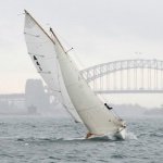
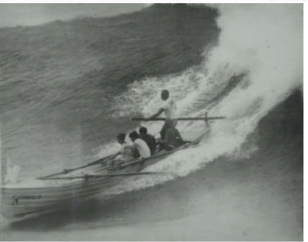
I was prompted to post this as our daughter has just taken up the chaotic & wonderful sport of surf boat rowing. The boats are unusual & interesting, & I'm not sure if the sport is done in other countries. The shape of the boats has become quite particular, to suit rowing out through the surf, round a buoy & back to the beach. It's pretty common for 30-40% of the boats to not finish a race & sometimes worse. The original boats were descended from double ended life boats, & during the 20C became the shape they are now, & even in the 1960s were used to rescue people. These days it is a sport only, as jet skis & surf rescue boards have taken over the rescue part. The boats have a very short & flared bow so they don't nose dive on a wave, & long tapering hulls & a lot of rocker. I imagine most people on the forum are interested in unusual craft, so here's one more. The still photo below shows the hull shape well, & something about what the boats are for, the video shows the fun & chaos of the sport. Incredibly, less people get injured than you would think....it gets pretty wild. summer wishes everyone!
-
Hi Patrick, An Arctic Char would be very very good - do you ever catch them? On ship matters, the interior of the forecastle is fascinating, I suppose they were never really empty on a ship of war - but it's almost a very modern piece of architecture.
-
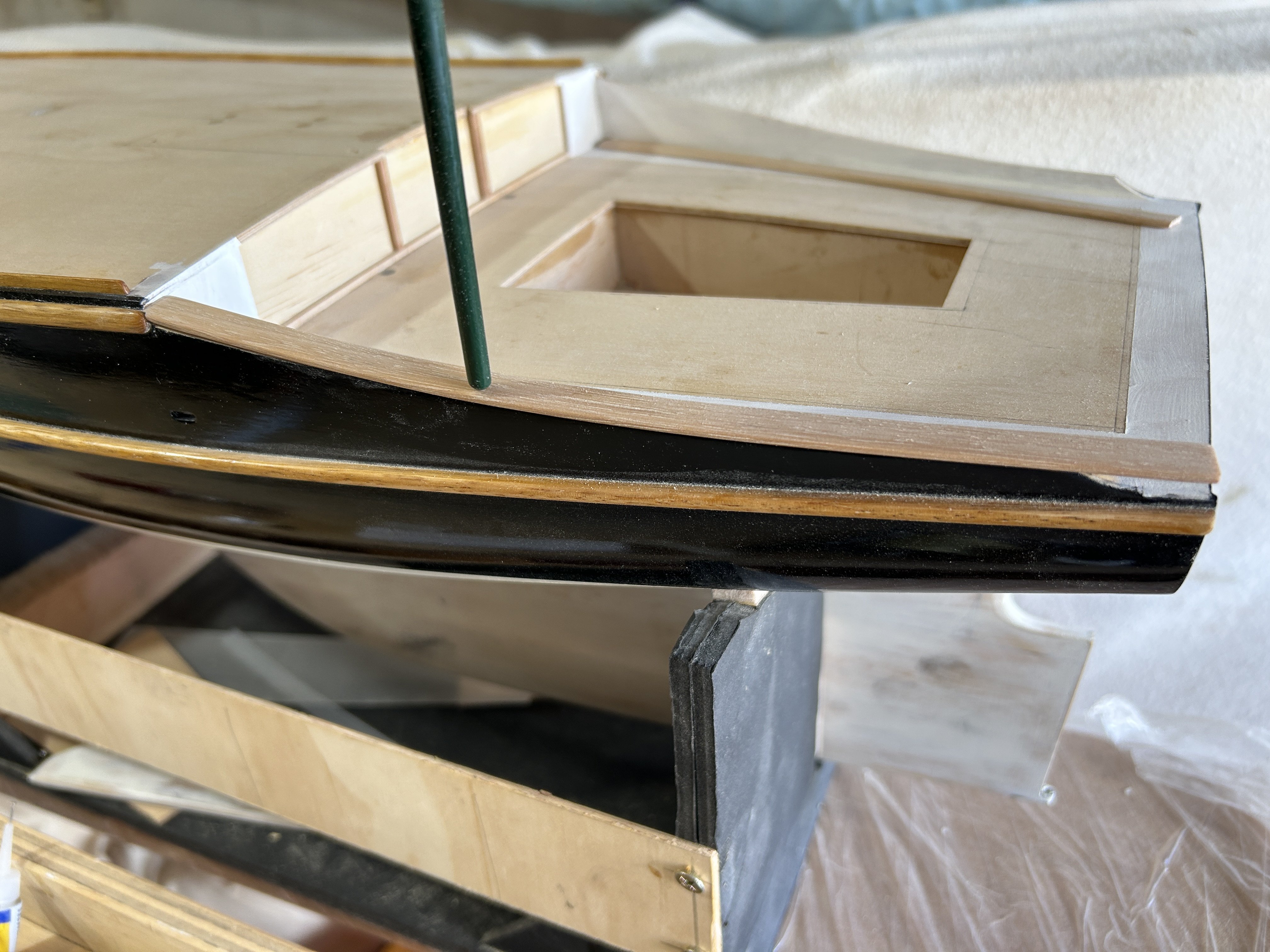
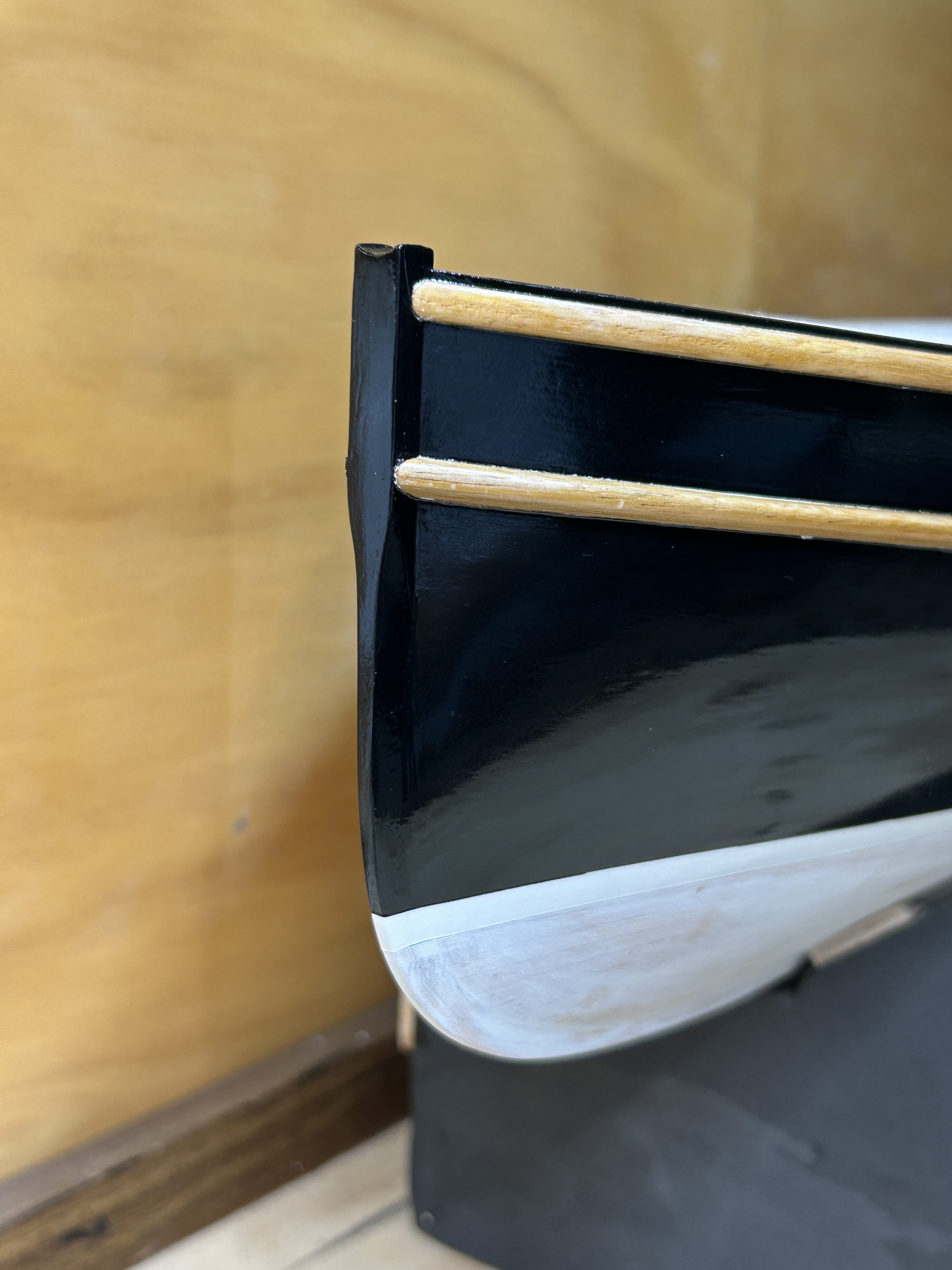
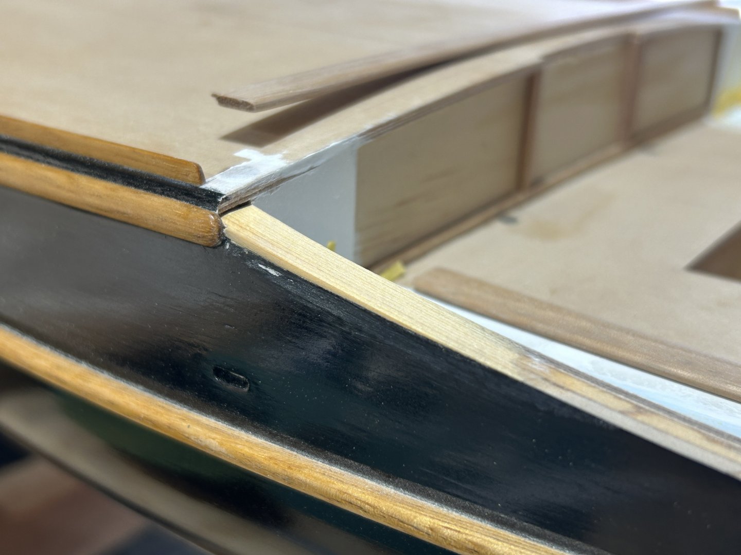
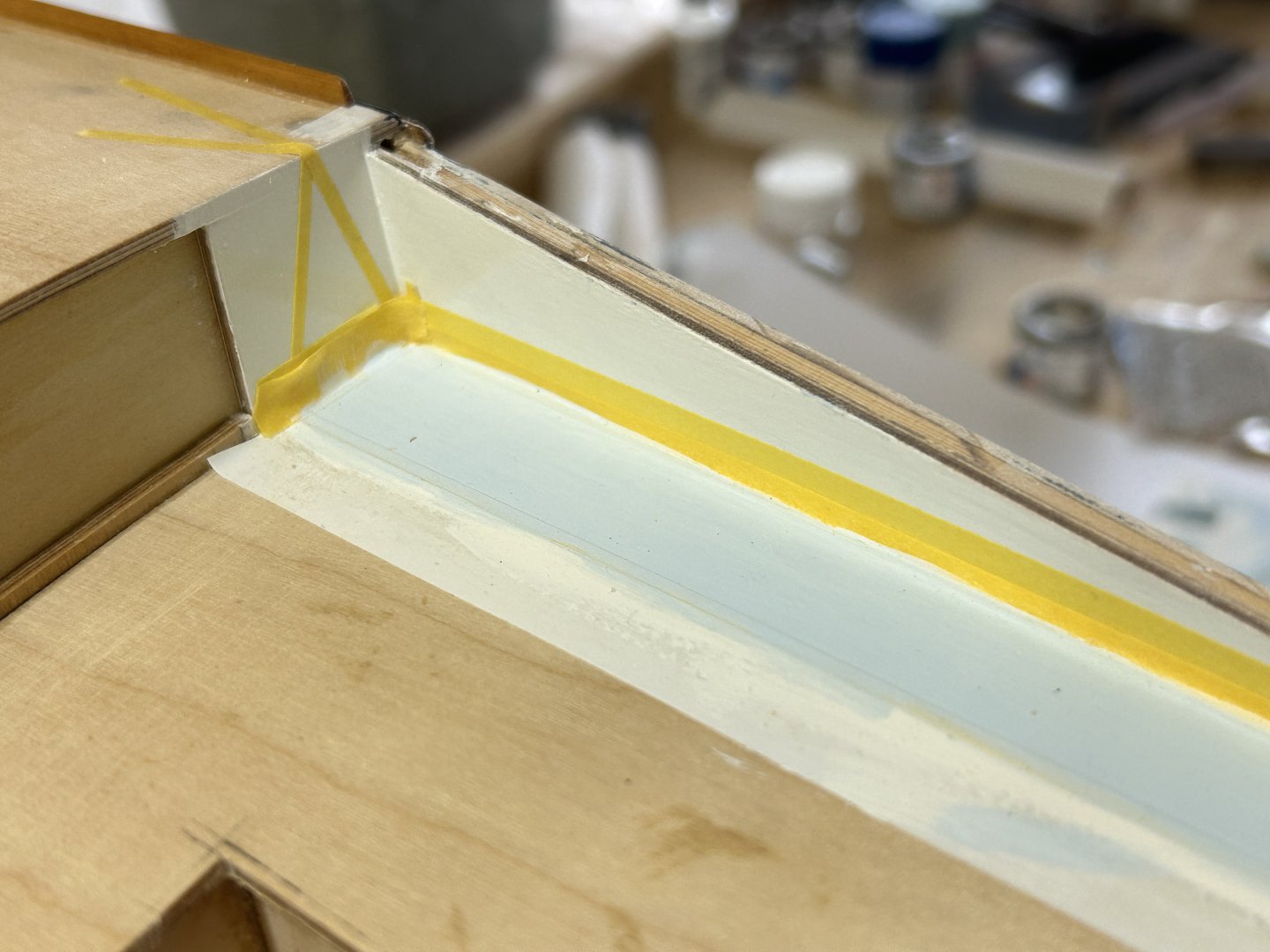
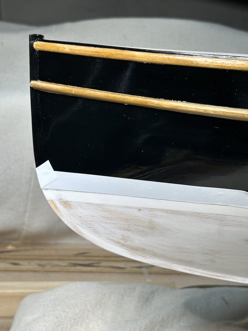
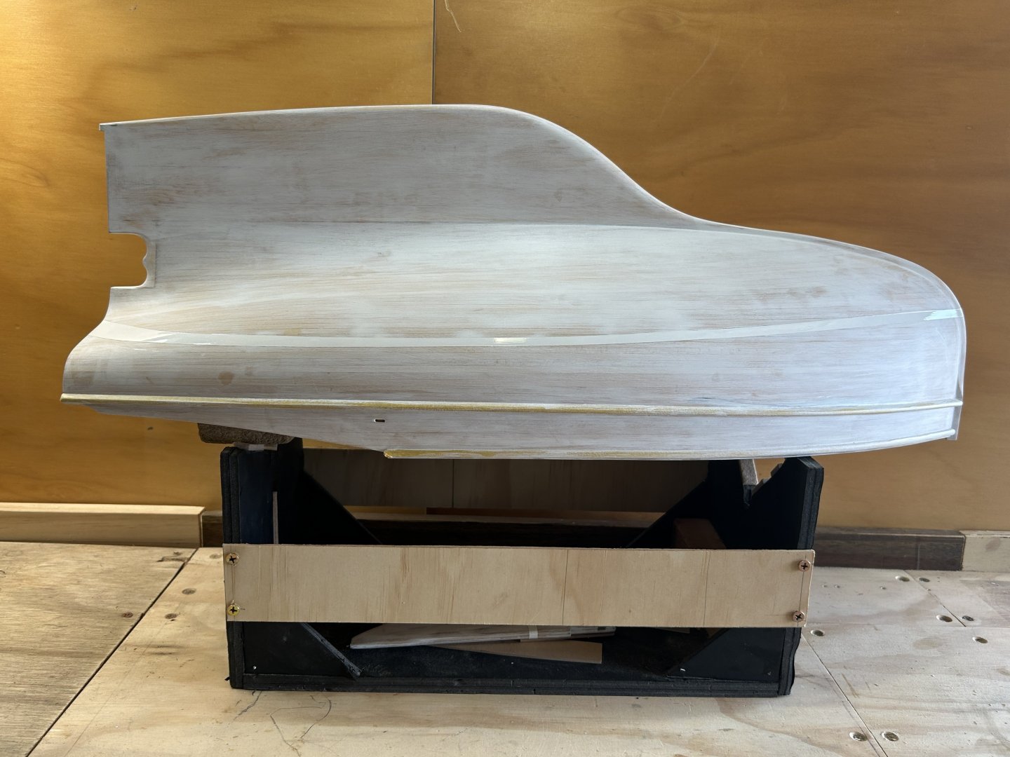
The hull painting is underway. I used a good quality household undercoat (Dulux oil based primer-sealer), as it sands nicely. As the boot top line is white & the hull topsides black, I painted the boot top first, in full gloss oil based enamel (Humbrol gloss white). Humbrol seem to have changed the recipe, but it went ok - but 4 coats were needed to get a really opaque layer. The flow was nice straight from the tin, but the density could be better. The underwater paint will be a matt acrylic of some sort, pale grey, or pale blue-grey; the topsides oil based enamel. After the photos I'll put some thoughts on gloss level at scale. I left the masking tape on the timberwork as I'll start the black now. And thanks to Tim Moore of this forum for the recommendation to paint some clear coating on the masking tape joint to reduce likelihood of bleeding under the tape. I did a test to check compatibility - which might be an issue down the track but it seems ok for the short time since i did the test. Undercoated, sanded & with the boot top done: This one is included to show something that to me was an important detail: the way the stem resolves to the hull as a crease, which then softens to become a faired curve some distance behind the front of the keel. The shadows show it, & it's about right to the actual yacht. For the topsides paint, I am doing a mix of Humbrol gloss black, plus about 25% Humbrol satin black added, plus a bit of Penetrol for flow. I might have added too much Penetrol as it's looking a little thin, but I'll do one coat & then judge whether to change the balance. The white boot top was left full gloss, but black will really show the gloss & I think full gloss at scale should be backed off a wee bit. This might not be an issue for a pale colour, but black will really show the gloss level.
-
Very nice Tim. The colour are harmonious but also credible. And I like that you can see the buoys are actually solid timber -