HOLIDAY DONATION DRIVE - SUPPORT MSW - DO YOUR PART TO KEEP THIS GREAT FORUM GOING! (Only 75 donations so far out of 49,000 members - C'mon guys!)
×

Mark Pearse
-
Posts
830 -
Joined
-
Last visited
Content Type
Profiles
Forums
Gallery
Events
Everything posted by Mark Pearse
-
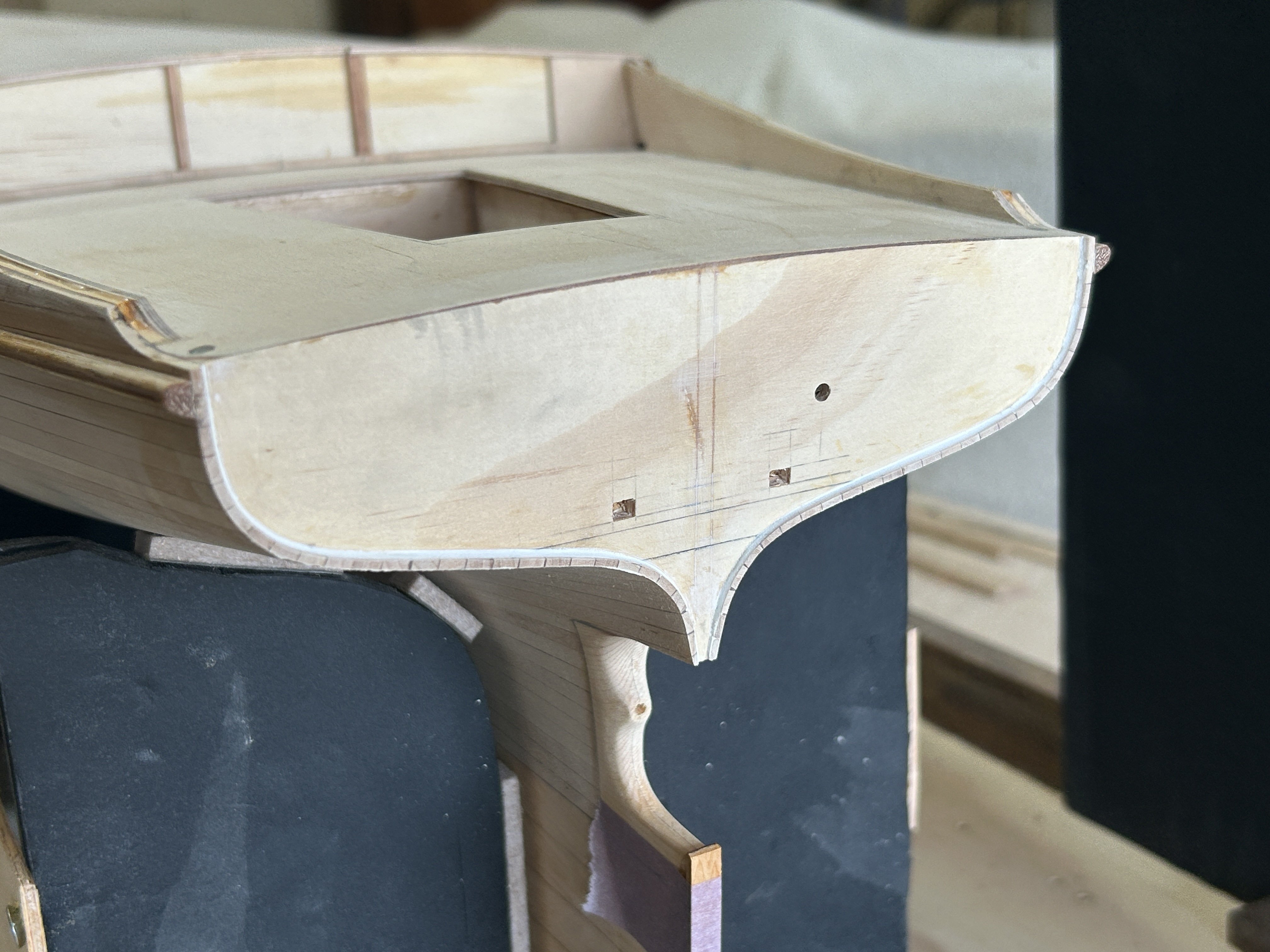
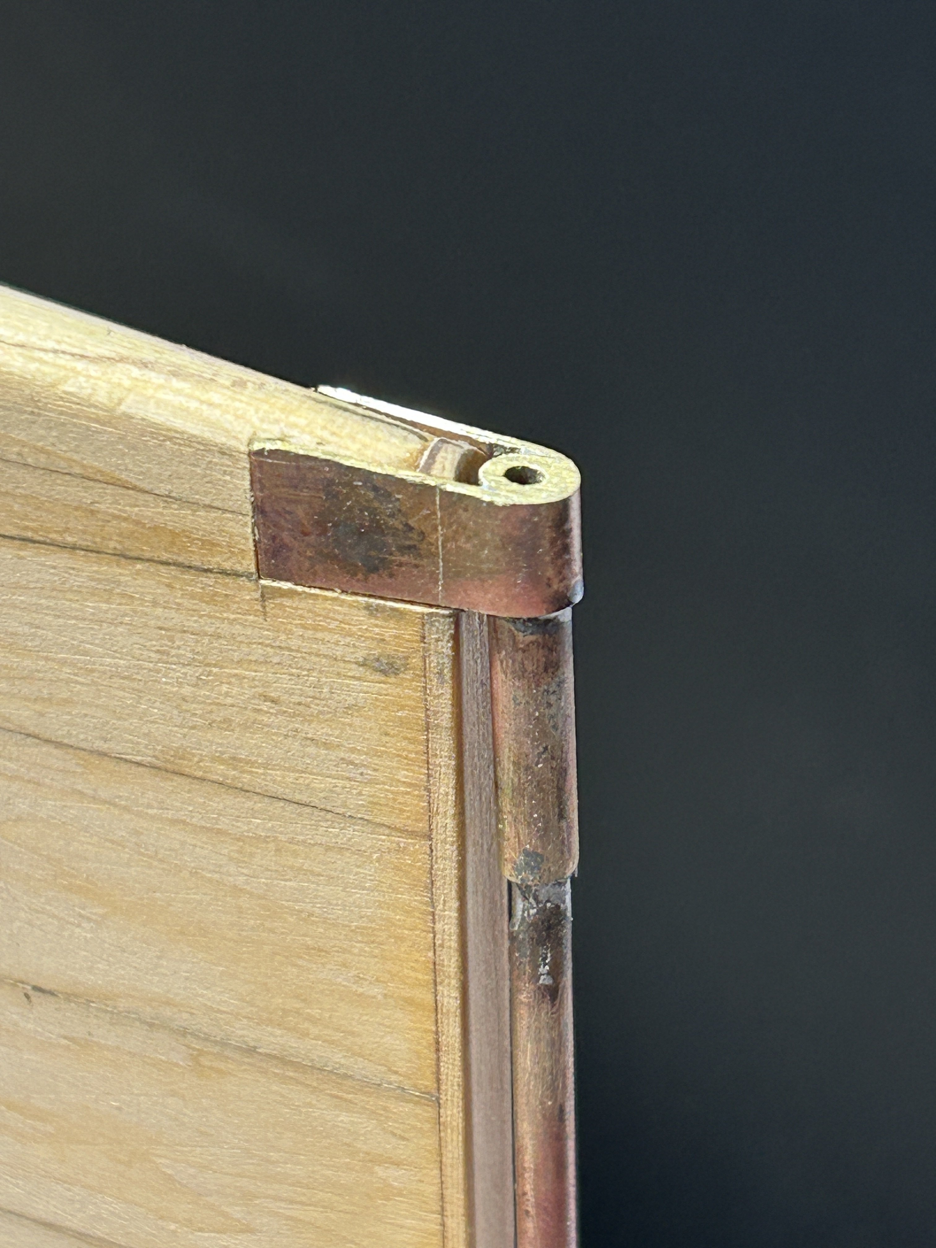
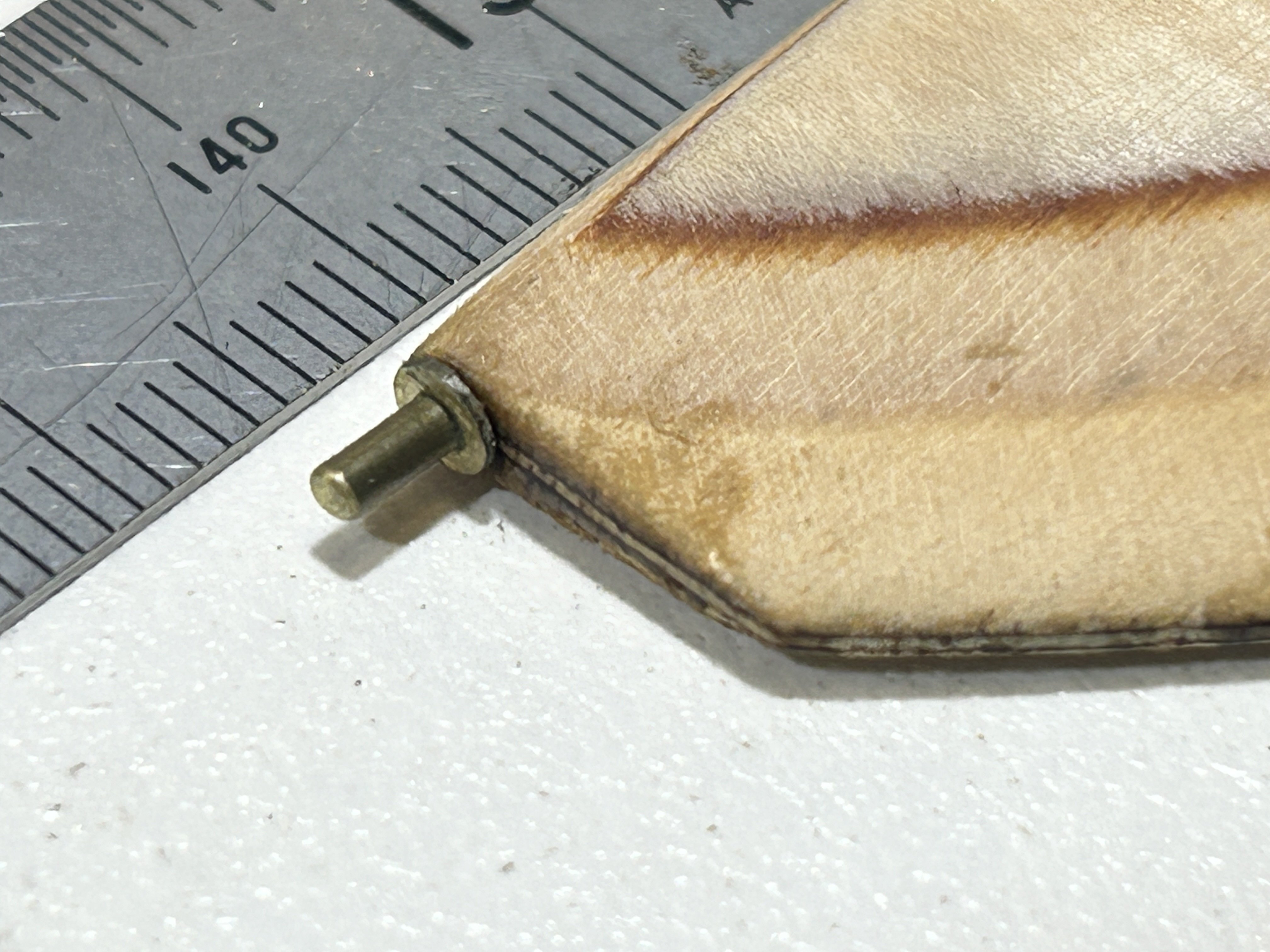
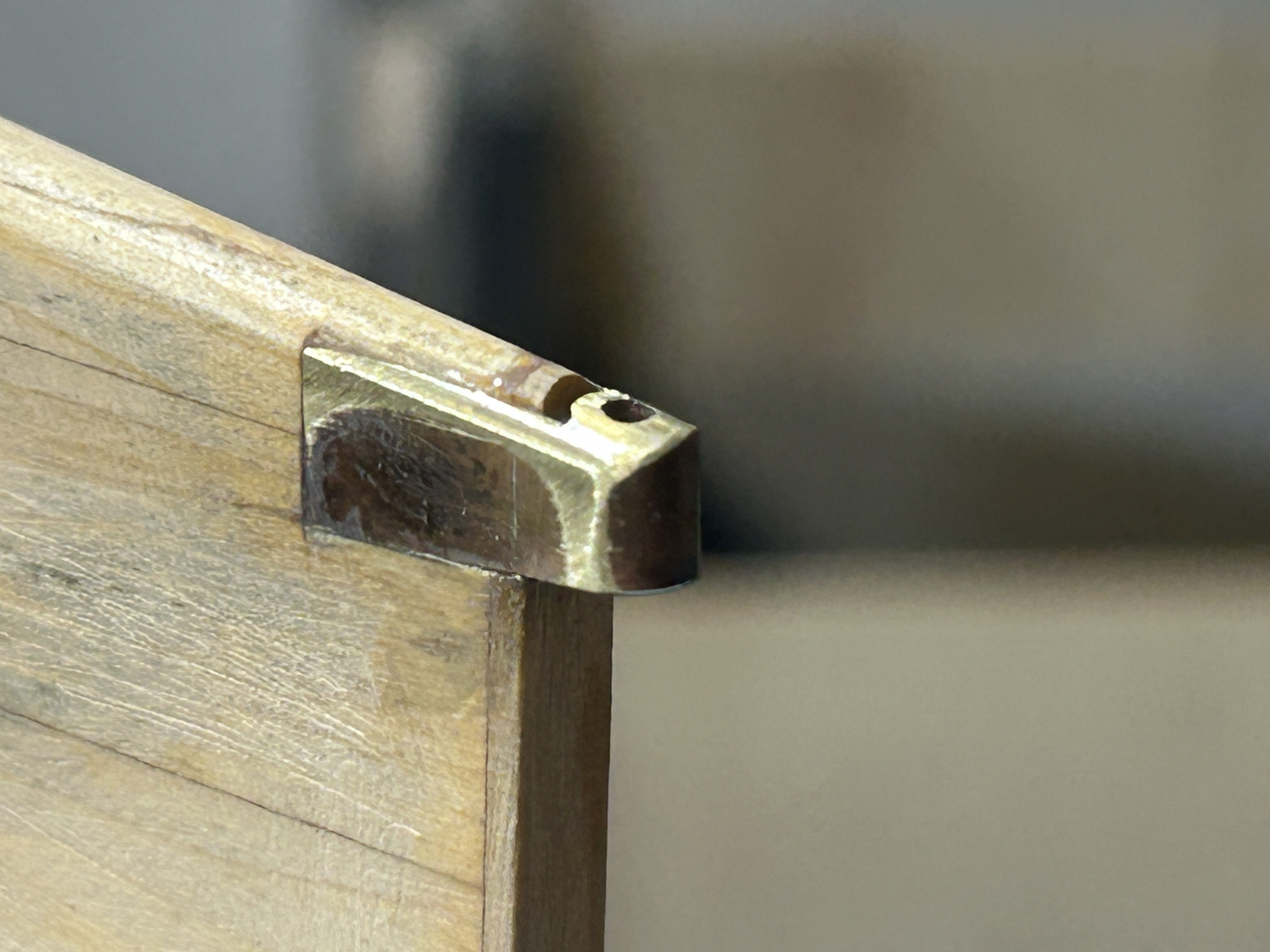
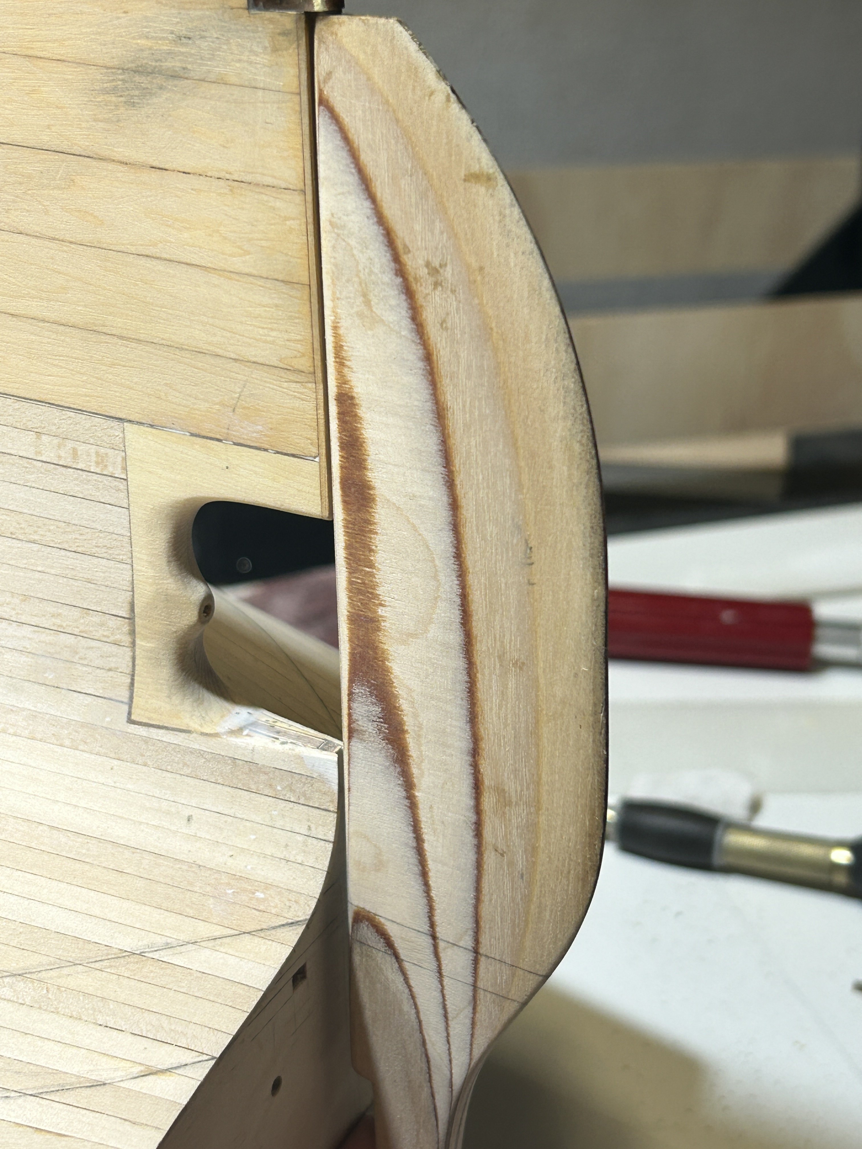
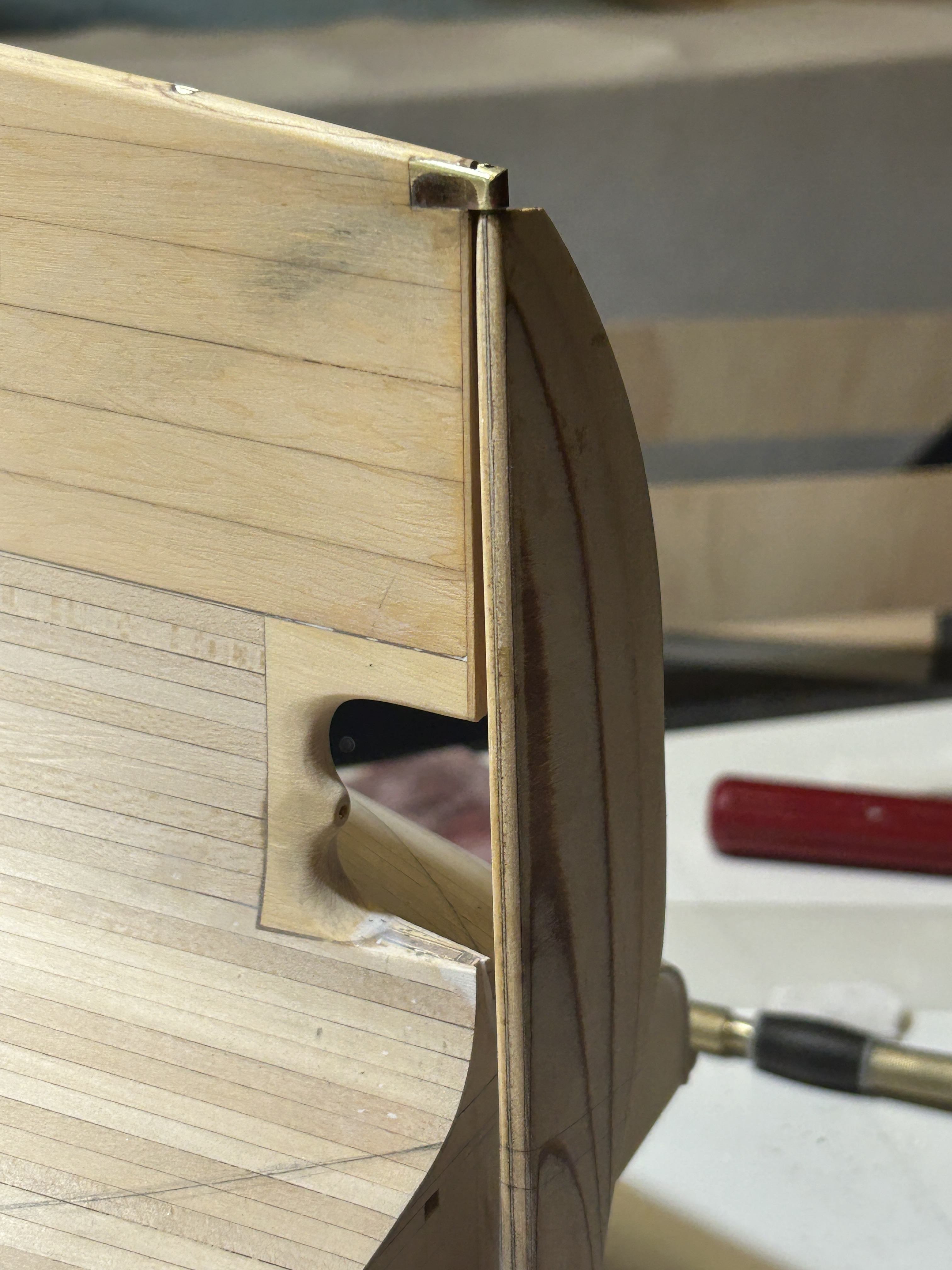
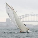
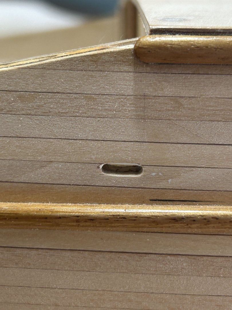
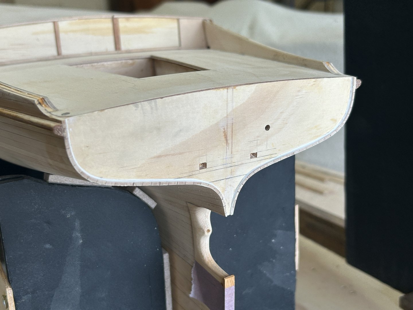
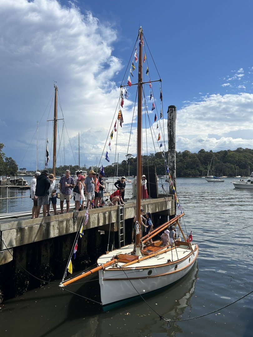
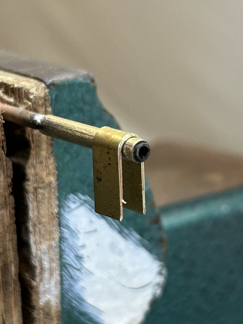
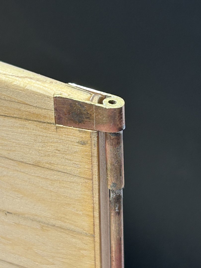
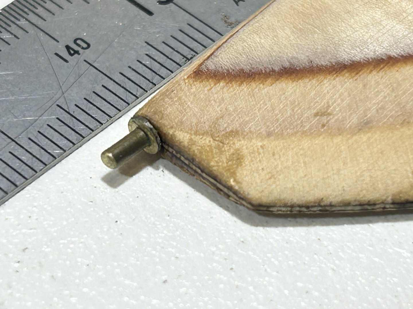
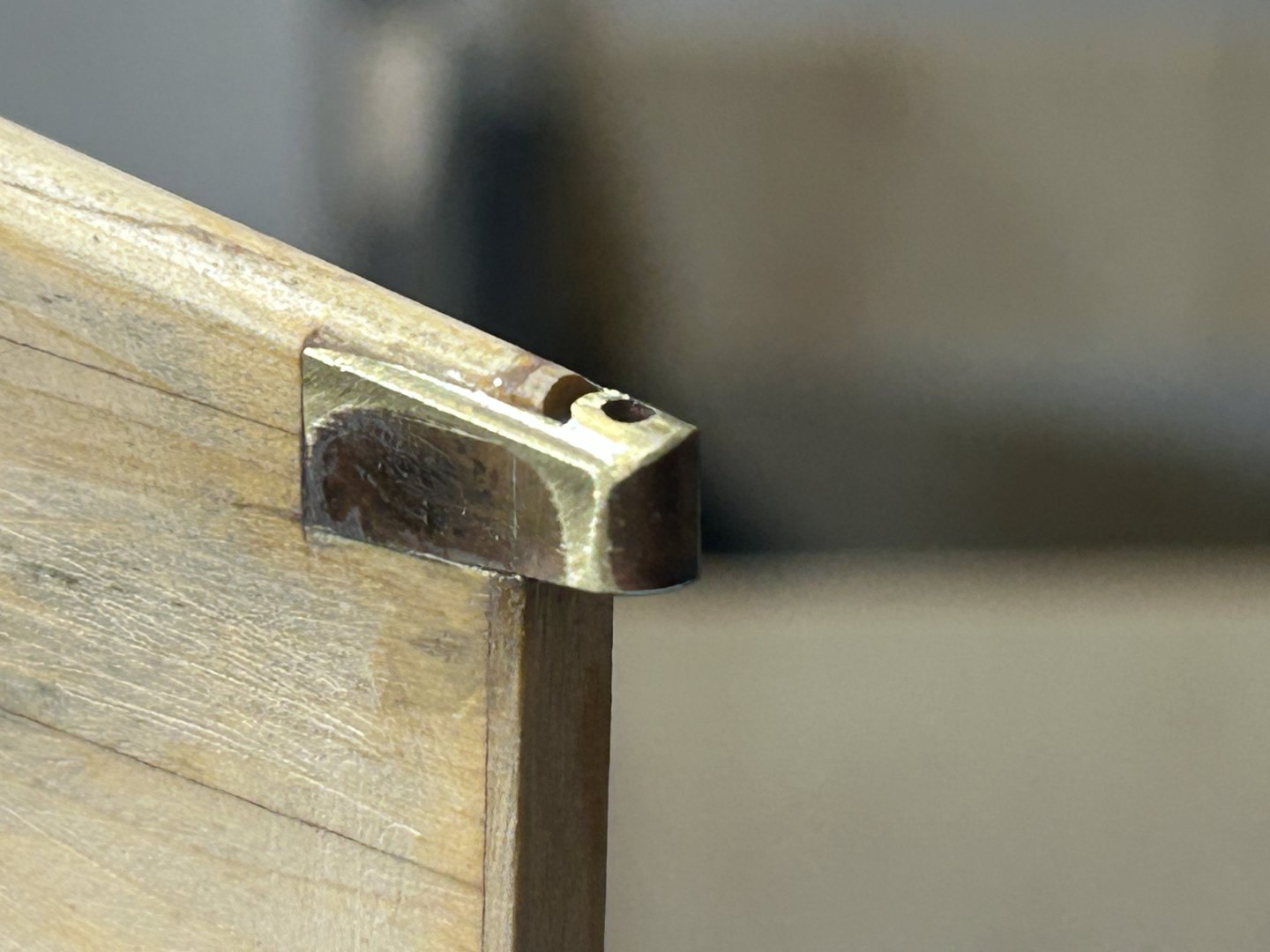
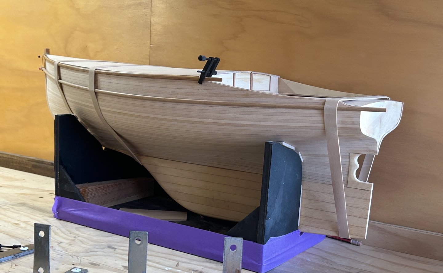
 I have been working away, heading towards painting the hull. There's been quite a few small & exacting jobs, not ones that give a huge sense of achievement, but necessary for a good paint job - & some bits that just had to be completed. Bowsprit / stem resolution (& boot top lines): Drain holes for the scuppers area around the cockpit: Stern apertures - the square ones are the cockpit footwell drains, & the round one will be the exhaust outlet; visible also is some filler to the inside of the planking / transom joint (hood ends??). I used sanding epoxy filler for that, & a tiny tiling wedge as a spatula - the end is such a nice combination of sharp & flexible for a tricky filling job. Plus a bit more timber to the lower aft edge of the keel, also visible. Also the lower gudgeon for the rudder, which required a careful setout.....the rudder blade setout is done very well & cleverly on this particular boat: you can see that the aft edge of the keel meeting face is concave & the rudder nests into it nicely - but they managed to also allow the rudder to have a full 90º swing. This is for picnicking, you take out the tiller & the freely swinging rudder doesn't knock against the hull all afternoon. The gudgeon is pretty simple but I had to sleeve tube into tube to suit the OD & ID, seen here with the piece that wraps around ready for soldering. Then shaped & dry fitted: & then glued in place & shaped, as it has been carefully faired on the actual boat The pintle below, & the spacer was a piece sawn off the gudgeon tube: And here's the rudder in it's home position, note the faired rudder to keel junction: And at 90º: And lastly, another build of these doughty yachts has been launched, Sunday 30th December, see below. Built by retired shipwright Ian Smith, & his freely available videos online, on boat building are really excellent. Well done Smithy & Trish!


-
Hi Steven, if you run short on White Oak, I have some small pieces doing nothing & could post to you.
-
is that a low compression diesel, & the hot bulb is like a permanent glow plug..?
-
Looks like a massive single cylinder putt-putt engine....
-
Hi Steve, Nice work on the wheels. Looking at the photos, the scolloped edge is fabric rather than rigid, so perhaps paper. Cutting that shape will be difficult though. I wonder if there's a craft scissors that do it, like the zig-zag ones but curved....Spotlight are good for stuff like this & just might have it.
- 110 replies
-
- 2
-

-
- Paddlewheeler
- Ballarat
- (and 3 more)
-
Hi Vaddoc, Very nice, & your metalwork is especially fine work.
-
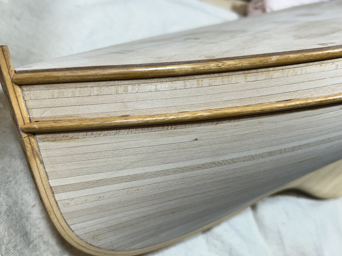
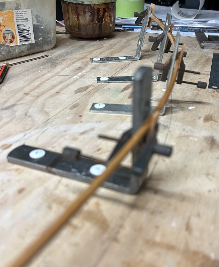
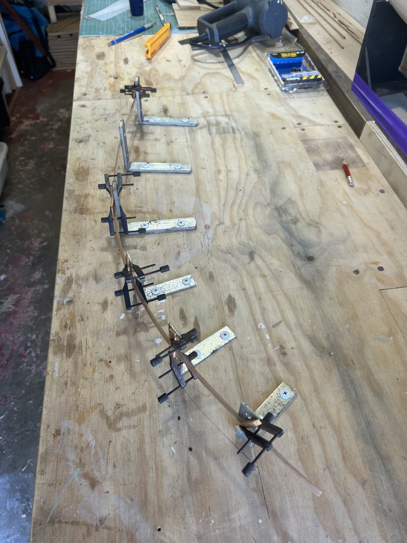
Onwards... I have glued both gunwales to the hull, & the port side sponson. The timber has about 4 coats of brown-orange shellac, finished with steel wool. I will give them another go before painting. The plywood deck had a prominent change in colour of the veneers at the height the top edge needed to be, below the deck line. For the gluing, I had swallowed my pride & decided on CA glue, as I didn't want to put any mechanical fixings through the timber as I couldn't see a good way to hide them, & using CA did allow just enough time to make sure the strips were accurately placed. The sponson-gunwale relationship is critical to the appearance, so errors were just not on. The port side sponson went on quite easily yesterday, & I had a go at the starboard side, which didn't go well... I was fighting some twist in the timber & was struggling to get a good bond with the load of that twist. I've learned that with CA, you need to get a good bond first time if you can, & the struggle had gone on too long. So, I pulled it off & set up the heat bending frame with an inbuilt twist....It's not much twist, but these native hardwoods have strong opinions & this one needed more encouragement. You can see from the pencil line on the bench that the brackets were repositioned & the upper legs bent. So the sponson is in the same basic curve ....just with some twist. It's now clamped, heated (heat gun) & on the clamps for for a day. Tomorrow, I'll sand off the dried CA glue from both surfaces (vip in my experience) & try again.
-
Interesting lines: the boats look fat but the underwater lines look as fair as any 20C cruising yacht. The garboard looks to have a lot of twisting to do... Nice drawings too.
-
Thank you, all very helpful. I'll probably use epoxy glue rather than CA, & pin the timbers in position so they don't slide & set in the wrong position - which would be bloody terrible..... Then spot fill the pin holes. I'll research some suitable pins. Hi Ronald, thank you - the planking looks good at least partly as they are pre-cut & therefore constant width rather than tapered. The actual yacht is strip-planked (ie: wood/epoxy composite using narrow constant width planks, with fibreglass & epoxy resin over), & the model is following that in the planking.
-
Thanks guys, I appreciate the advice.
-
Hi Andy I'm no guitar expert, but that's a gorgeously classic shape. Understated & well proportioned indeed....
- 174 replies
-
- 2
-
-
- Vigilance
- Sailing Trawler
- (and 1 more)
-
Hi All, I am building a 1:20 model of a small yacht. The hull topsides will be painted (black) & there's a gunwale & sponson on the topsides. The gunwale, at scale, is about 1.5 x 4.5mm, the sponson about 4 x 7mm. The setout of the sponson is important to the whole look of the yacht, so needs to be accurate. I can paint first, then glue the timber , or glue then paint. In the first case, painting is easier as there's less cutting in; in the second, getting the sponson setout right is easier. I'm posting this here to get some advice on this. I am probably painting with a brush. thank you all in advance...

-
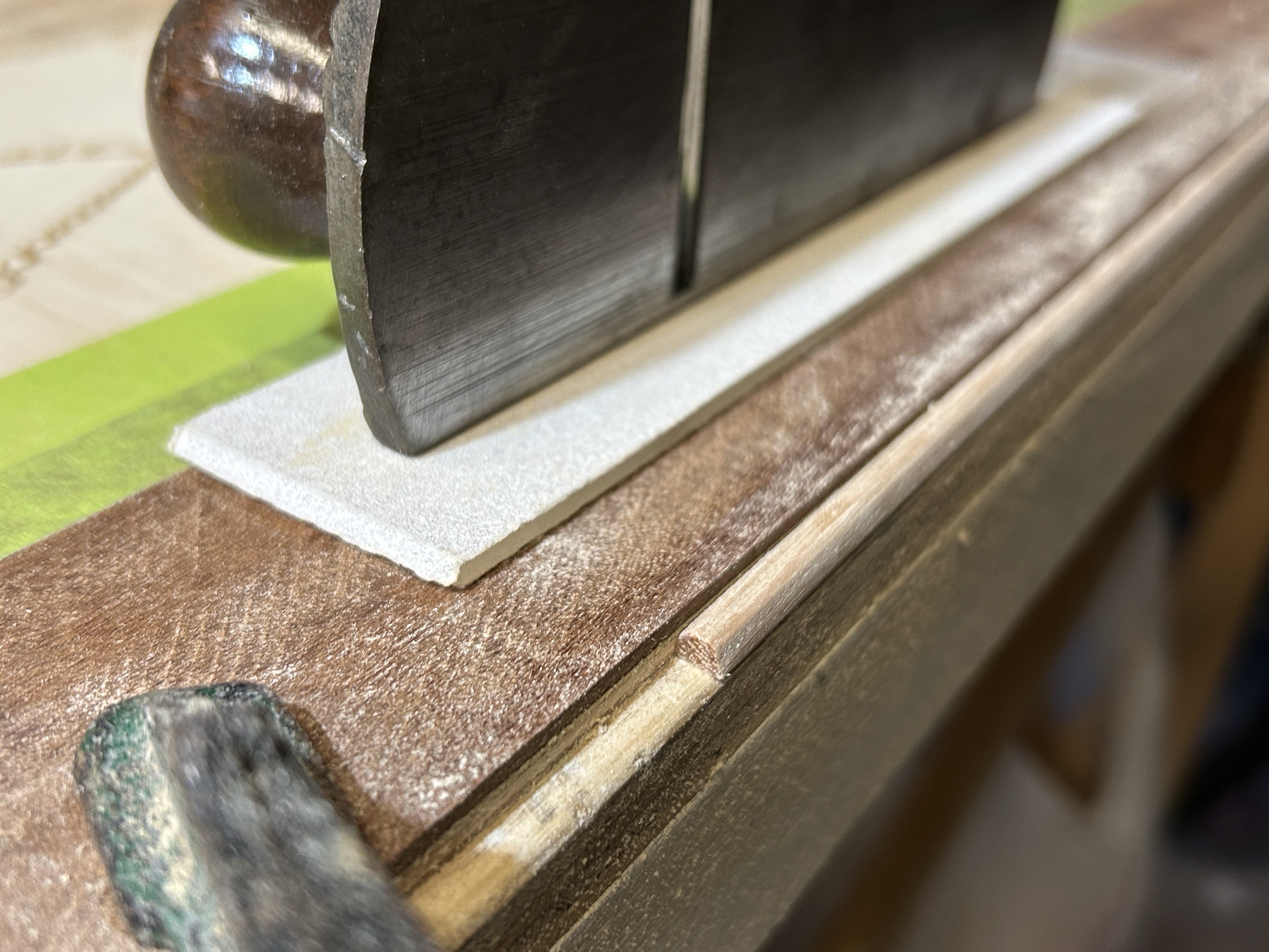
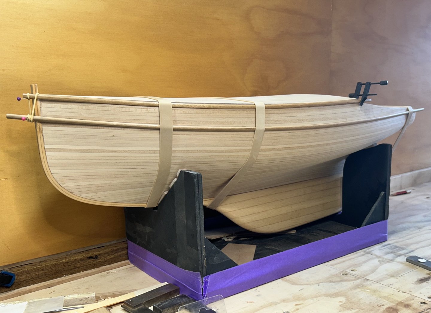
The current progress is towards painting the hull. Concurrent with the work below, I am working on some test panels for a hull paint - but just a little on my thinking: black shows gloss more than other colours, & as a gloss object at scale will look more real if the gloss level on the model is less than the actual...I'm going to be a bit fussy on that. The sponsons need a bit of assistance to make the curve of the hull shape, & fortunately Blackbutt respond to some heat reasonably well. My method was to scribe the hull shape on the bench, adding a bit more curve to the shape. Set up some angle brackets, clamp the middle one & heat sections (with a hot air gun) away from the middle & progressively clamp them. I suspect this isn't as good as actually making a small steam box & then clamping, partly because you haven't got much of an idea what effect the heat is having on the timber. Anyway, it worked well. I also gave one half of the gunwale the same treatment & then put them on the hull in a temporary way. That's partly so they have somewhere to stay while retaining the curve. Looks great. The last part of the sponson near the stern droops a bit, but that can be tweaked later. One aspect I'm not sure about, & would certainly welcome opinions: whether to paint the hull then glue the sponsons / gunwales, or glue them & then paint the hull. Painting is easier in the first case, getting the timber strips accurately positioned is easier in the second. I am leaning ever so slightly towards the latter. It would be good to get whatever opinions I can, from you all.... I'll also do a post on the in the paint section of this forum... thanks in advance,
-
Following Keith's lead, I also went back to the first photos, & that cap railing looks very nice, & seems to be more in scale
-
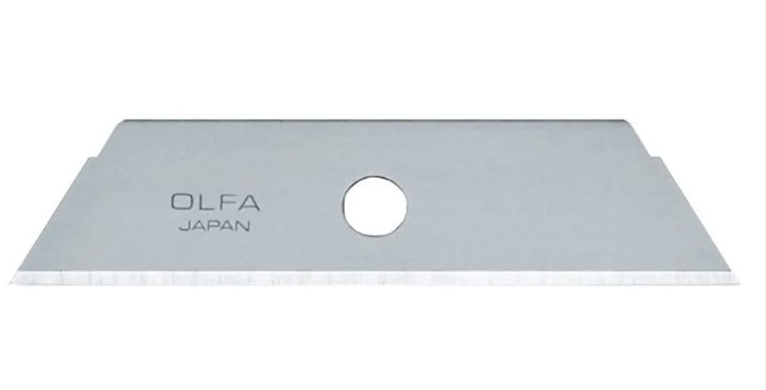
Hi Keith I have done something similar for a picture frame. It never occurred to be to try that for shaping these. By 'craft blade', do you mean like a blade from an Olfa style knife? as below
-
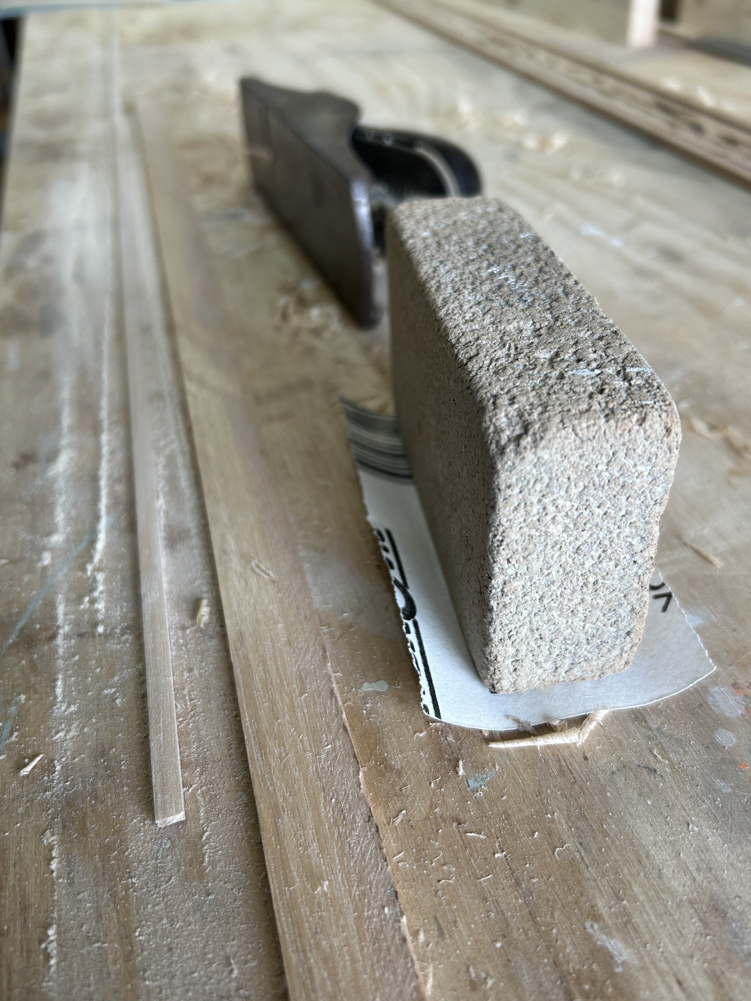
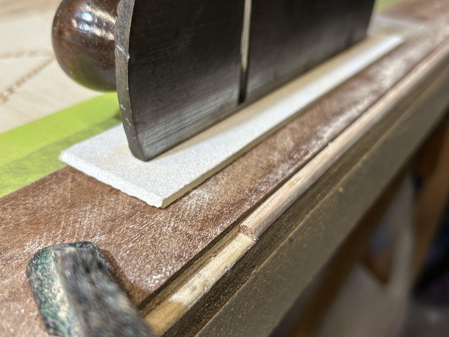
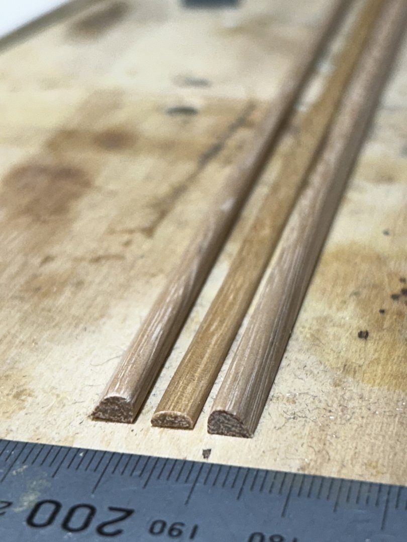
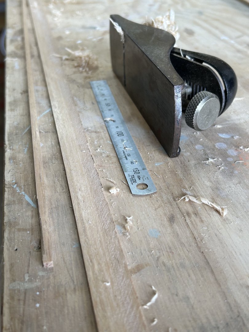
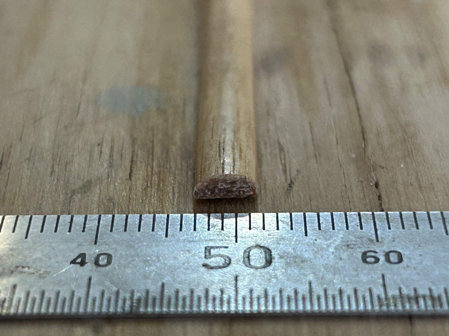
A little more.... The sponsons are now shaped. Below is the method I use for holding the strips while shaping, & my tools of choice; which works for 1:12 but techniques that work at this scale obviously might be an issue for much smaller scales. The back of the sanding block is 240 grit, & I have some finer (the softness of fingers helps sand curves), also some fine steel wool. Here's the strips: 2x 700mm lengths of sponson, 1x 1m of gunwale (a thin coat of shellac, hence the colour).
-
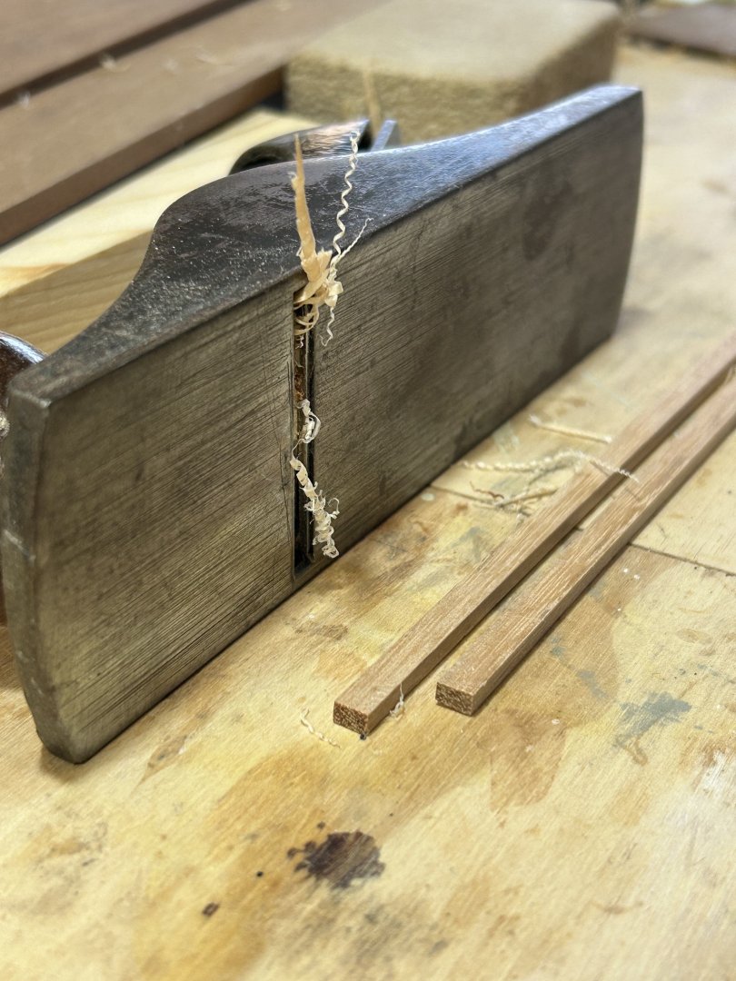
I decided the next major job is to paint the hull, & before that I have to make & position the gunwales & sponsons. In particular, the sponson line is important to the hull's appearance, & must be just right. It's mainly about the tapering gap above the sponson, between it & the gunwale. Hence the need to do both. The gunwale position will be a constant distance below the deck line but the sponson is tricky. My plan is to use brass pegs as dowels to fix the final position, put them aside & install after the hull is painted. On the actual yacht, the timberwork around the cockpit is teak, varnished or unfinished; & the hull timberwork is Spotted Gum - a tough hardwood that steam bends well. On the boat they have faded somewhat so I have used some Blackbutt that I have, a length of floorboard from a building site. I ripped some strips off on a table saw & then used a well sharpened plane to bring the timber sizes down further, & then to shape them. The strip on the left is a future gunwale, about 2.5 x 4mm. And shaped, finely sanded & one coat of shellac wiped on. I'll do some more coats later. Below are the future sponsons, about 4 x 5.5mm.

-
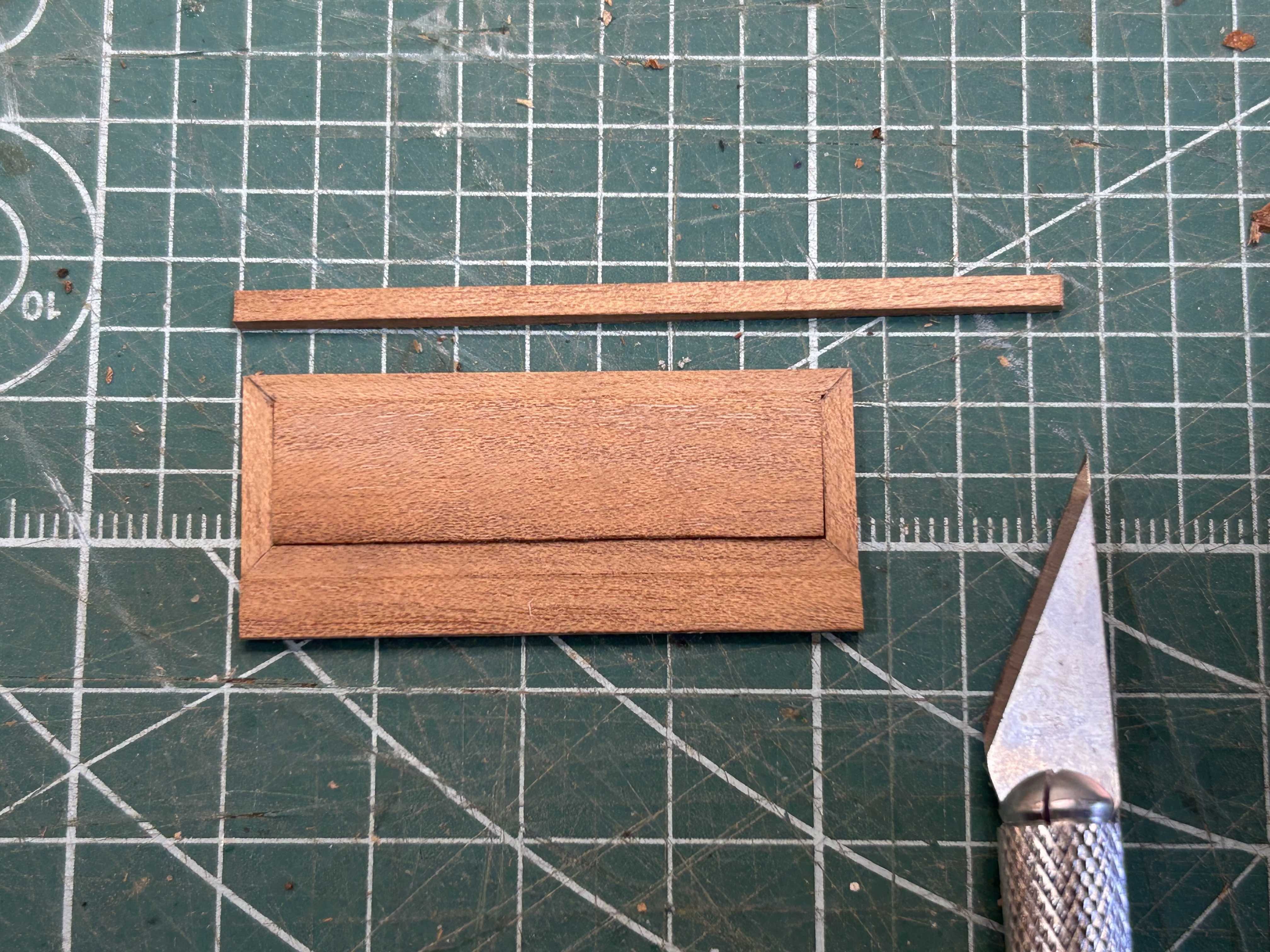
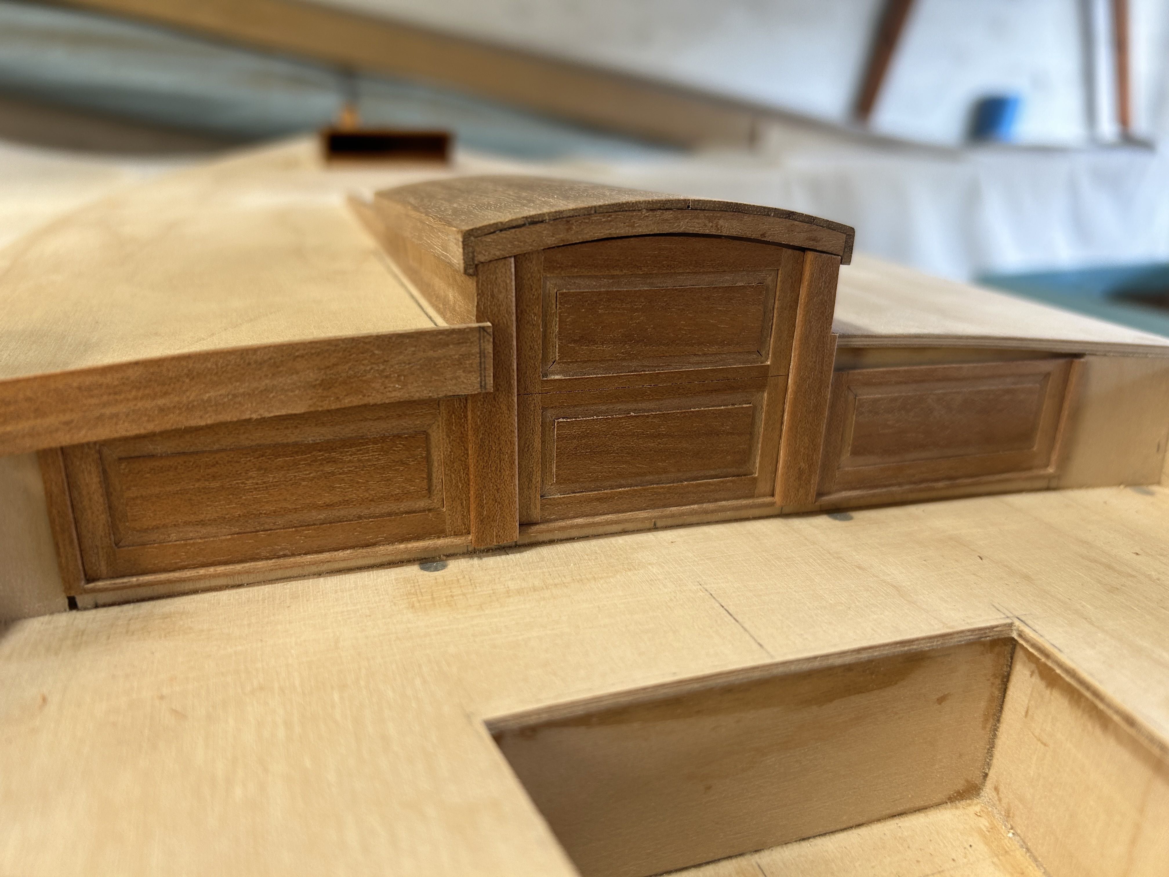
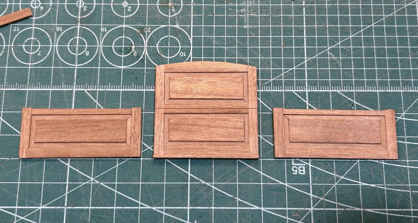
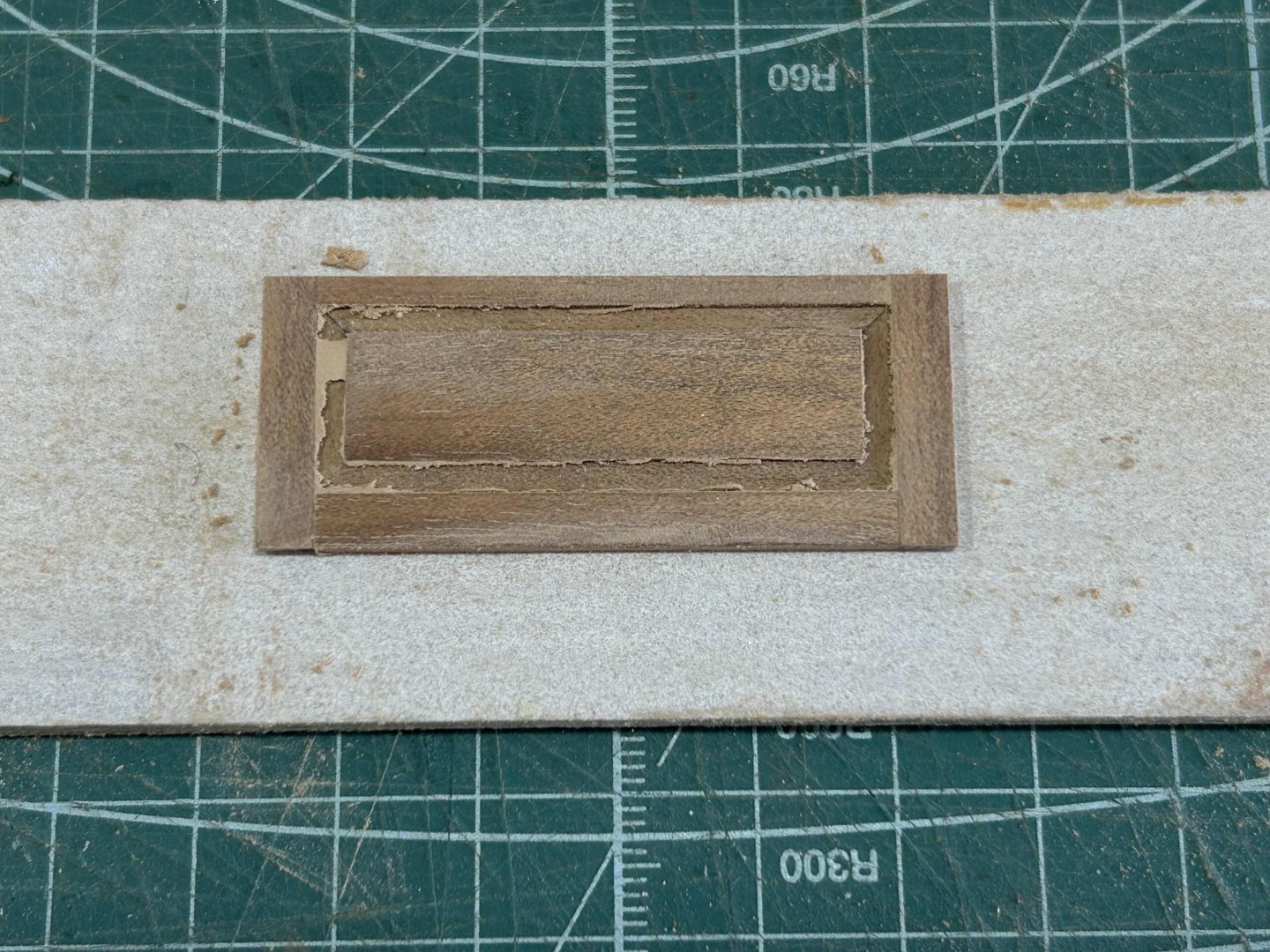
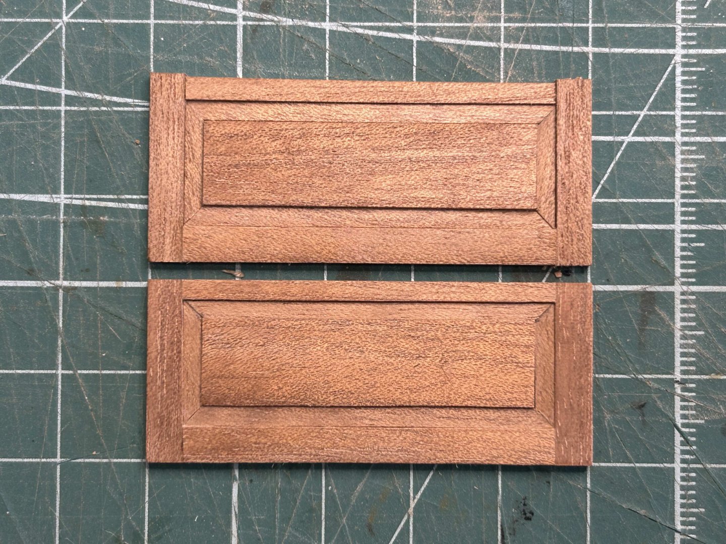
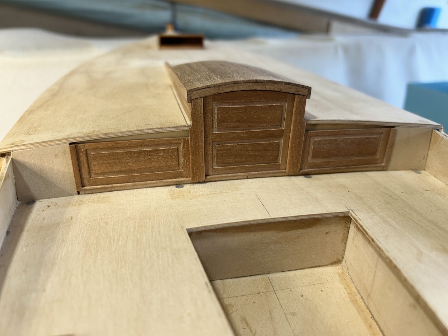
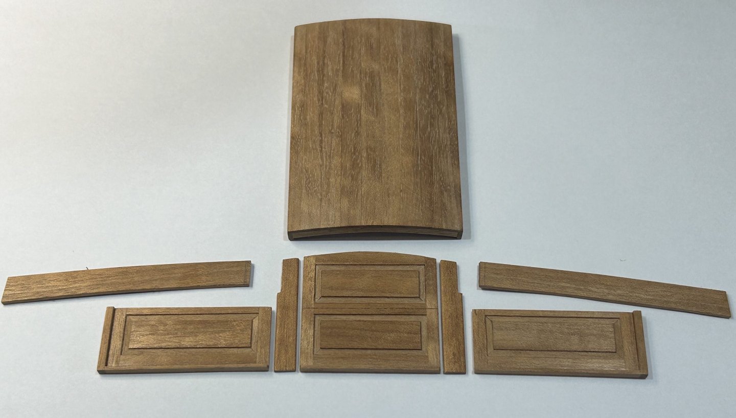
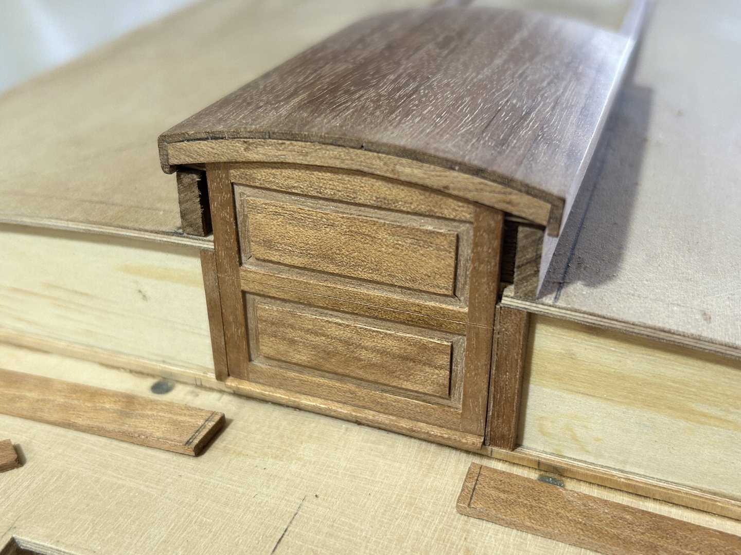
Thanks all, Druxey, when I was still drafting manually, I used 5H on plastic film. Nice sharp lines & no smudging. Some progress with the same area, the vertical face of the raised deck. Some further detail, in response to Rick's question. Everyone has their own method, & I have done it this way: The removable side panels that sit either side of the companionway hatch have a flat centre panel with a recessed surround frame, & then rails top bottom & sides, like a mini door. I didn't chamfer the surround frame strips, just recessed them. Nice sharp knife, careful measuring & careful gluing is my approach. Important is the opti-visor, being able to see is essential. Then sanding on paper glued to acrylic pieces. One sanded & one not...the effect of some careful sanding is nice to see. An important part of model making indeed. Dry fitted, with the separating frames that will be fixed to the side rails of the hatch. There will be curved members that trim the back edge of the raised deck. The bottom edge is slightly raised as the cockpit seating is laid teak, I've allowed 2mm for that. I've realised that this work can't go further until the hull is painted. So I'll put this aside for now, I'm changing tack & will make the toe rails, gunwales & sponsons. Then paint. bye for now,


-
Hi Jim Looking back to the early part of this log, the change has been incremental but significant; & I was also reminded of how this project must be a meaningful completion of work started by your mate George. As an aside, I am lucky enough to have visited Åland (also called Ahvenamaa), & had a happy day wandering around in the warm sunny summer weather. Keep up the great work.
-
Having the tackle suggests the position or angle of the steering piece was adjusted, have you come across any commentary on that?
-
Hi Rick The panels have timber in 2 thicknesses, & using a sharp knife I cut strips from thicknesses timber to suit the pieces: centre panels & the rails in thicker (approx 2mm), the recessed pieces that surround the centre panels are about 1.25-1.5mm thick. Then just assembled & glued as I went. I made a small 45º angle tool, to get the corner mitres for the recessed strips fairly accurate. I have 2 more panels & will photograph some of the stages. I've been using a pencil, a regular pencil with timber etc. It's hard to keep them sharp enough to mark really accurately, so I'm thinking to go back to a 2mm granite clutch pencil with a rotating sharpener....getting a pin-sharp tip will be very helpful.
-
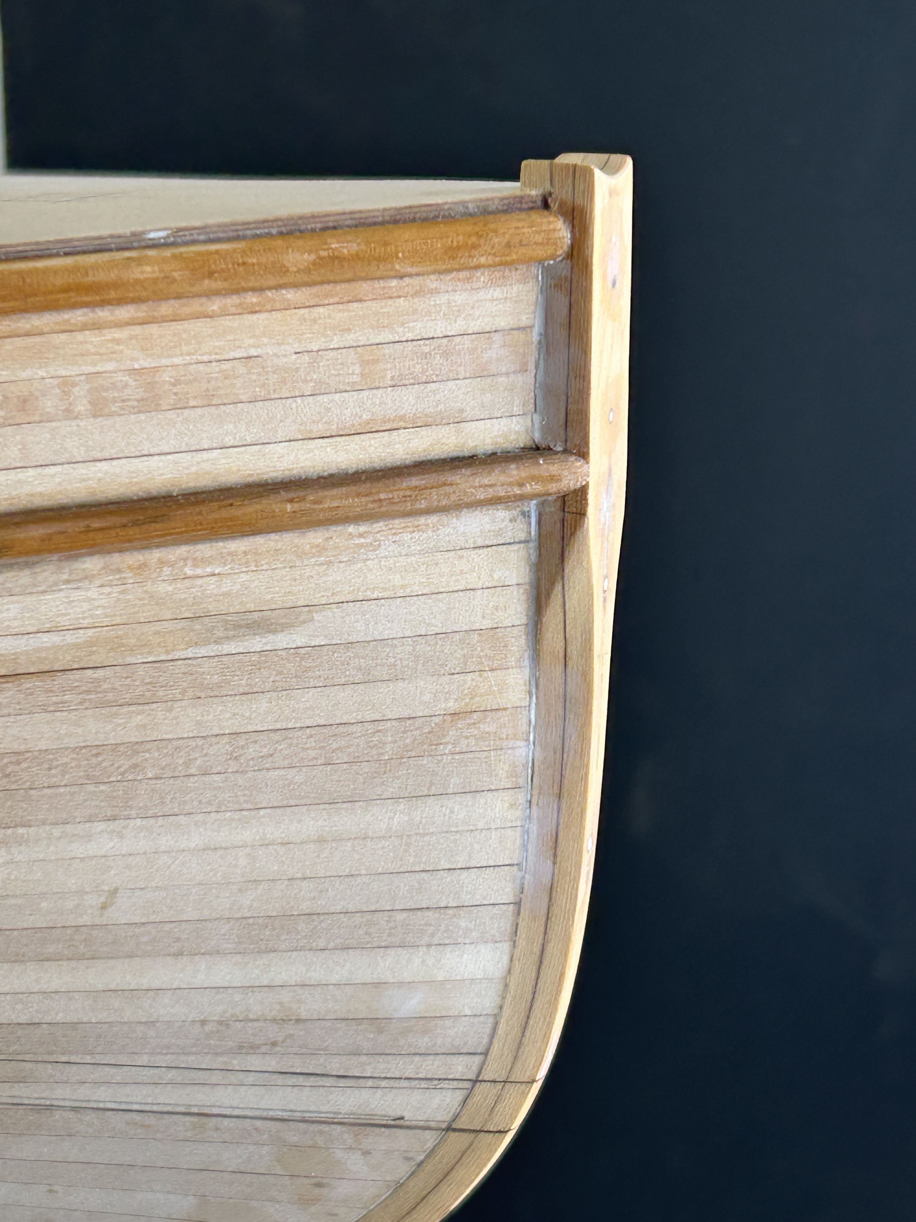
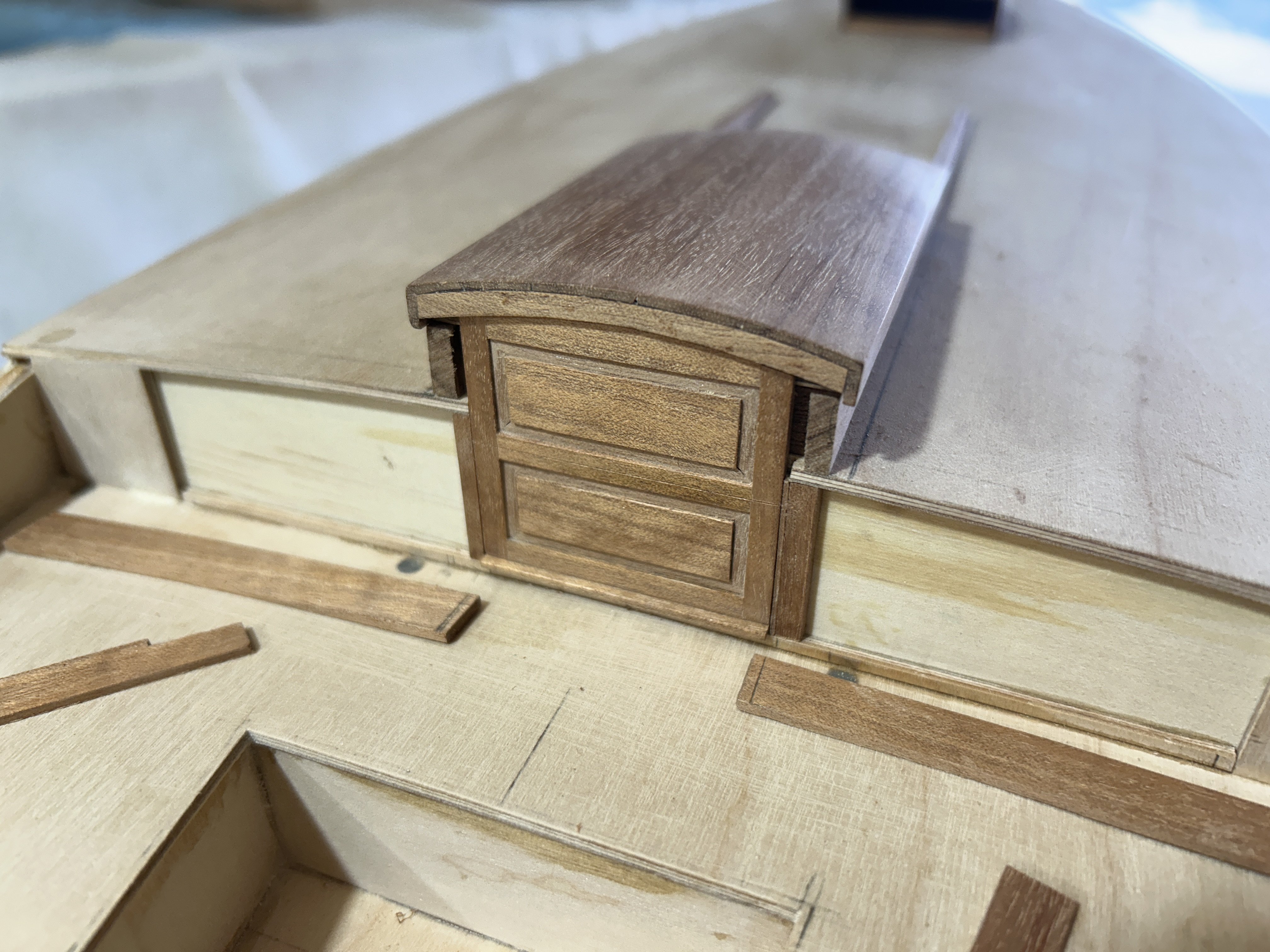
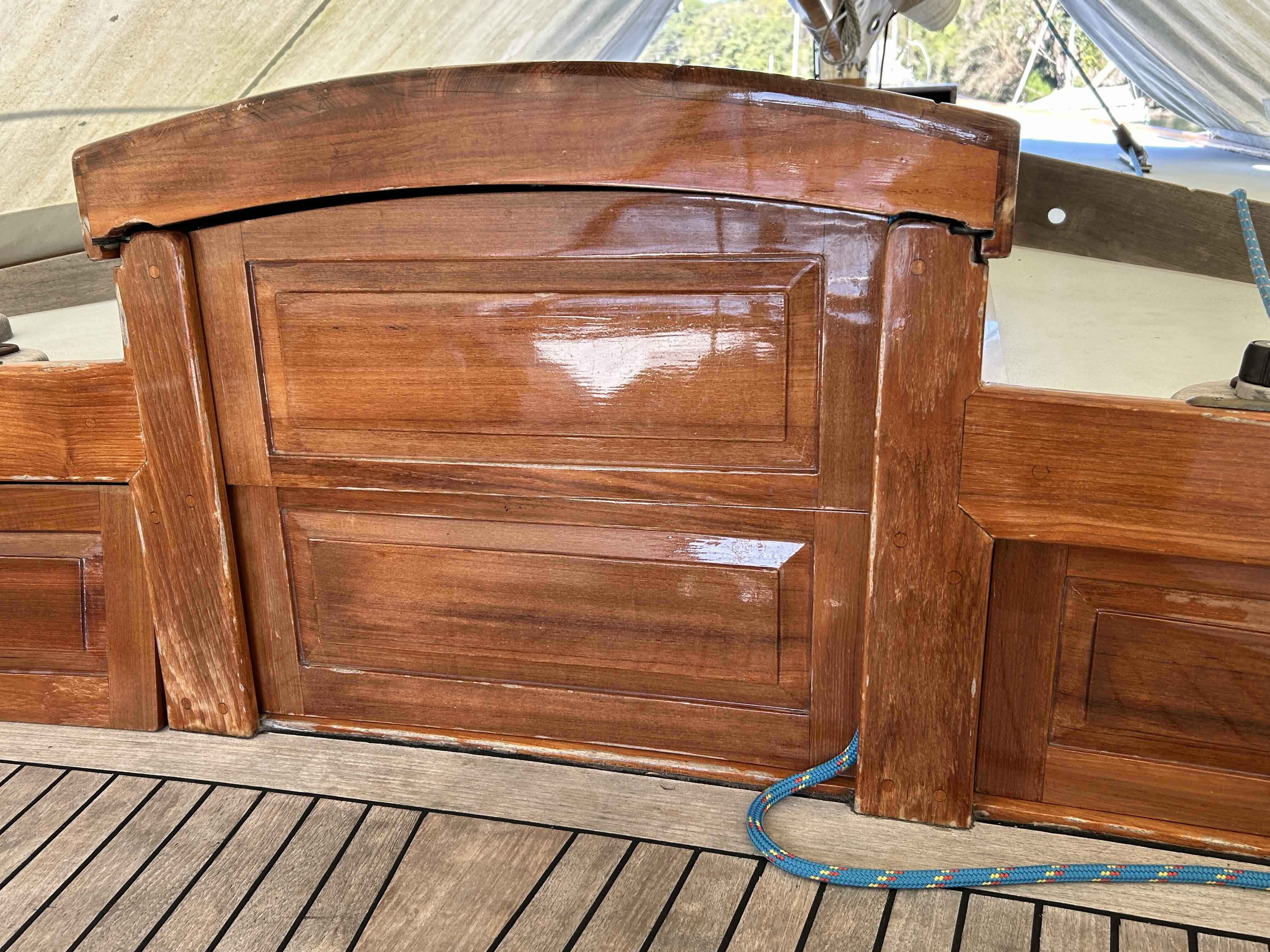
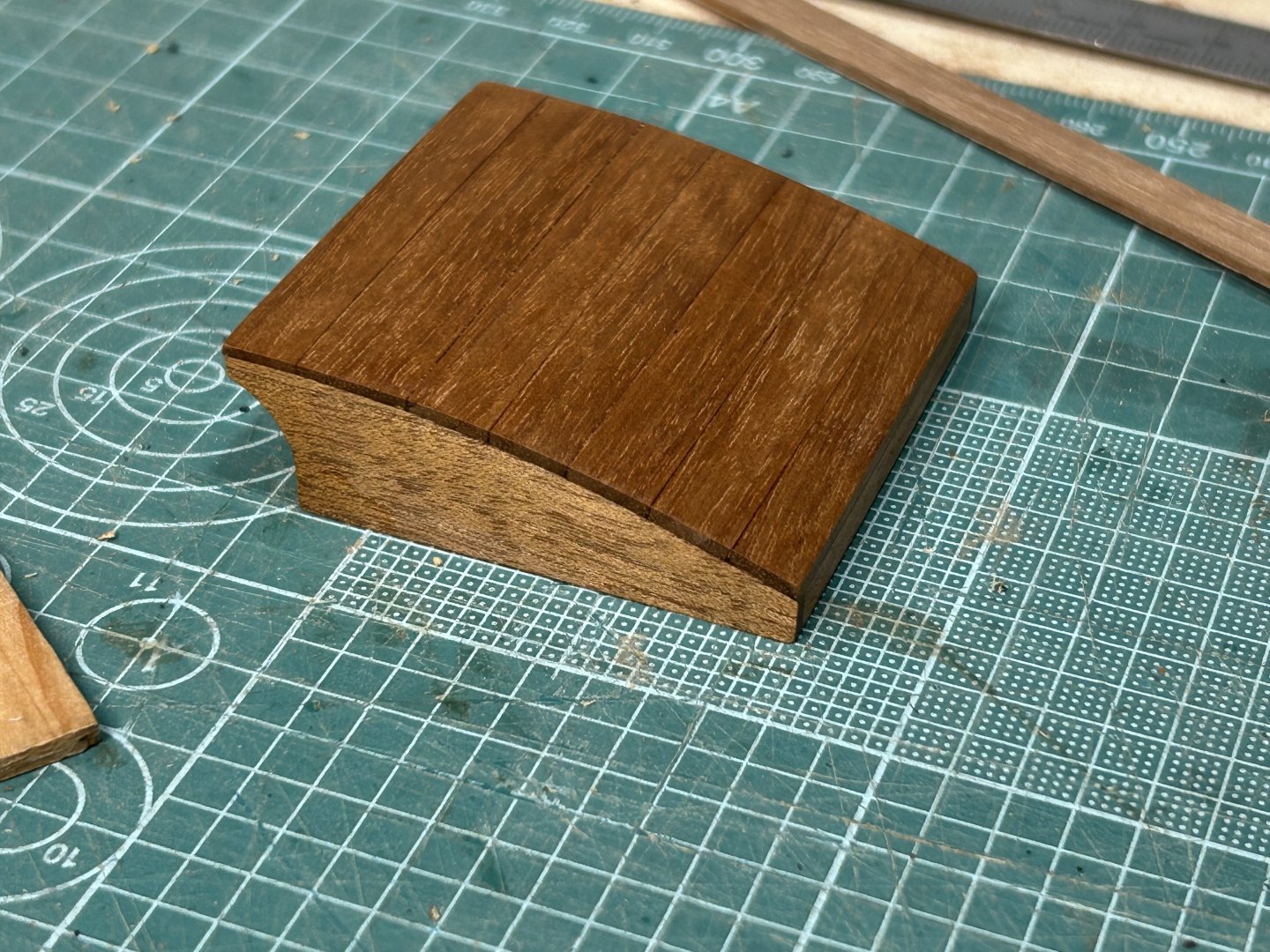
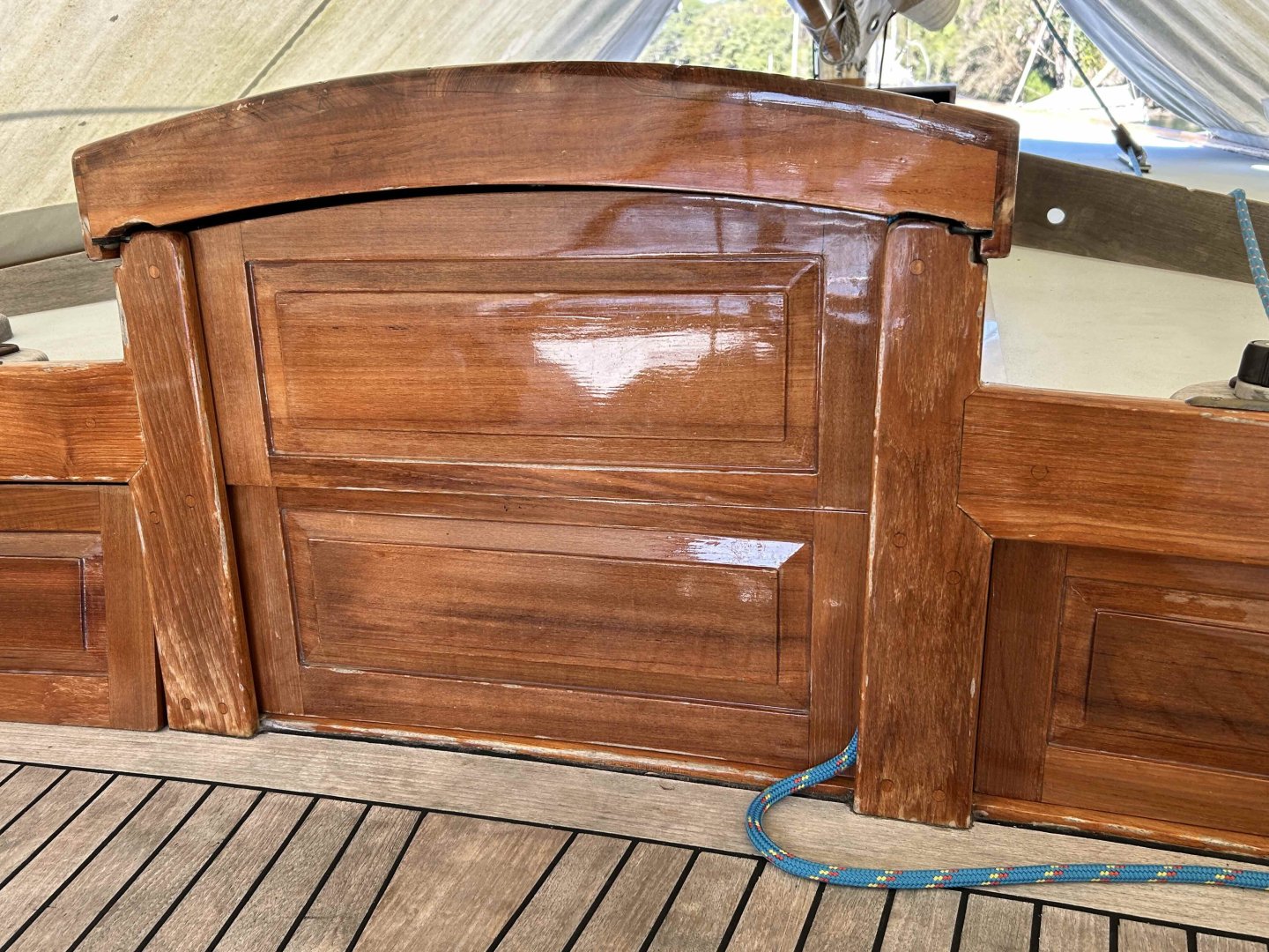
Thanks everyone for the interest. A short update: I have done some more on the varnished teak work of the raised deck. I have done a fair bit of preparation & pre cutting of timber. Here's the raised deck face with the storm boards done, no finish yet. There will be vertical frames either side of the boards, as per the 'actual' photo. The work light seems to be bleaching the colours also. And harking back to an earlier discussion, the CA glue stain in the forehatch really backed off over a few days. I gave it one coat of shellac to enjoy the thrill of a finish coat...The timber is the same colour on top & the vertical side, it just reacts strongly to the angle of the light.

-
It's a great pleasure to see the model coming together, & I really like the ageing you've done (to the boat...).