fnkershner
-
Posts
1,595 -
Joined
-
Last visited
Content Type
Profiles
Forums
Gallery
Events
Everything posted by fnkershner
-
Ben - I am sorry you missed the meeting. Since this model is to be used as a teaching tool and never leave the classroom. The school declined having any kind of R/C. They were more interested in things moving that would inform the students. Such as the thrusters, search lights, and the winches. We volunteered to have the fire nozzles rotate, and you will see that when I have the wiring done for the pilot house. The school has decided to mount the models to a roll around cart. This way the students can simulate being on the water and the correct angles on the nav. lighting. So when we are done there will be a 4 ft. long cart and a 7 foot long cart in the classroom. They will also use the winches to tie off to each other. A quick note on the Foss Waterway museum - As Ben mentions it is located in Tacoma and it has 3 models that were built by members of our club. They are 1 inch to 1 foot scale. I encourage anyone in the area to go see them. The model of the Discovery (the ship that discovered the Puget Sound) is 10 feet long and 12 feet tall, complete with Treenails.
- 133 replies
-
- 4
-

-
- alert class
- tugboat
- (and 1 more)
-
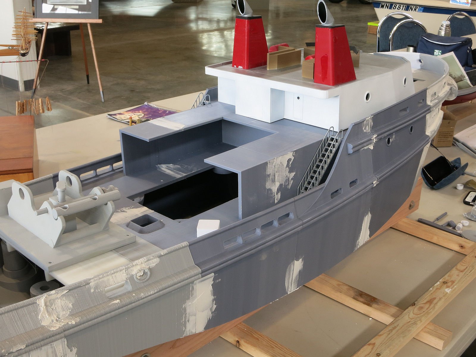
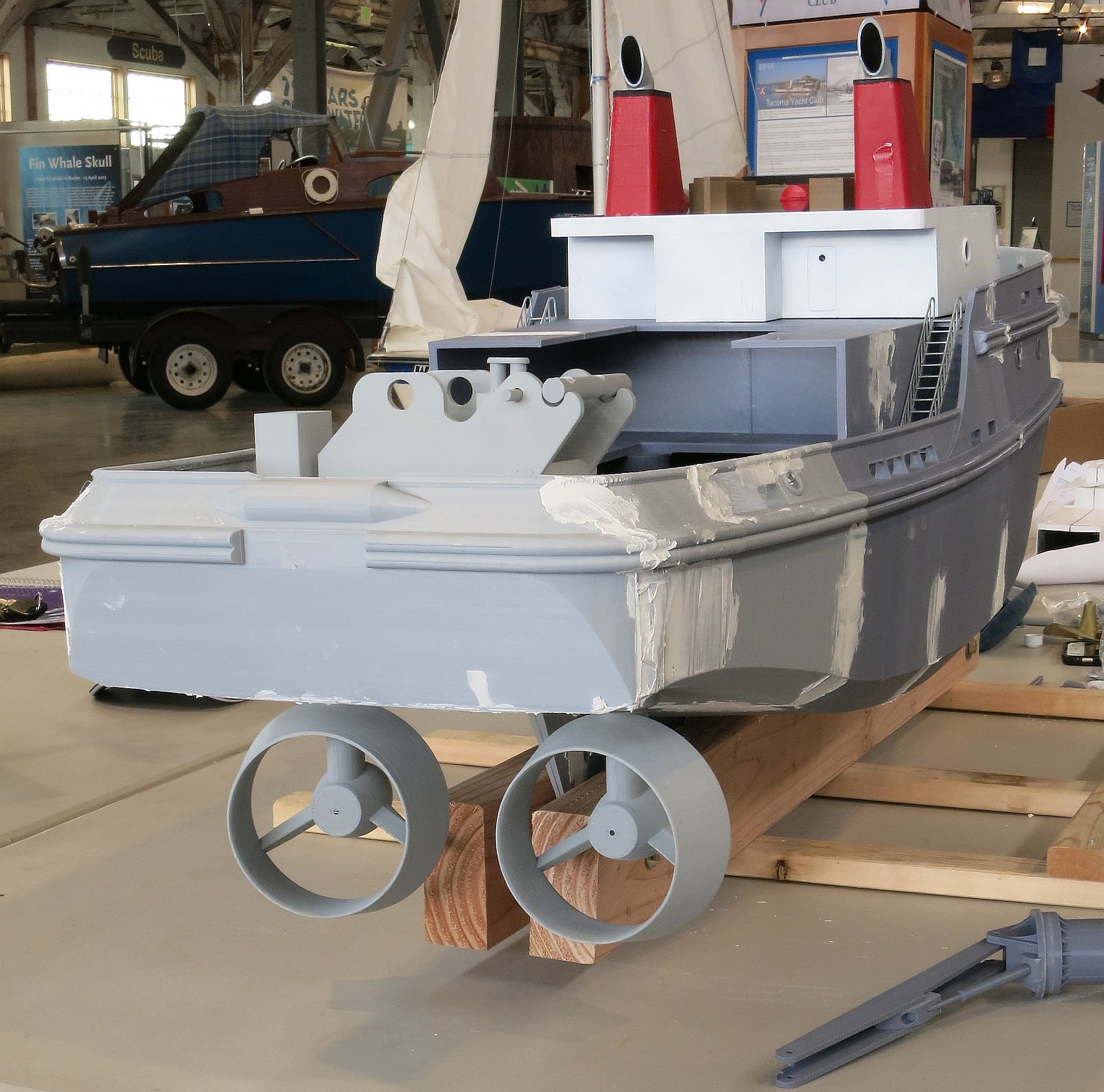
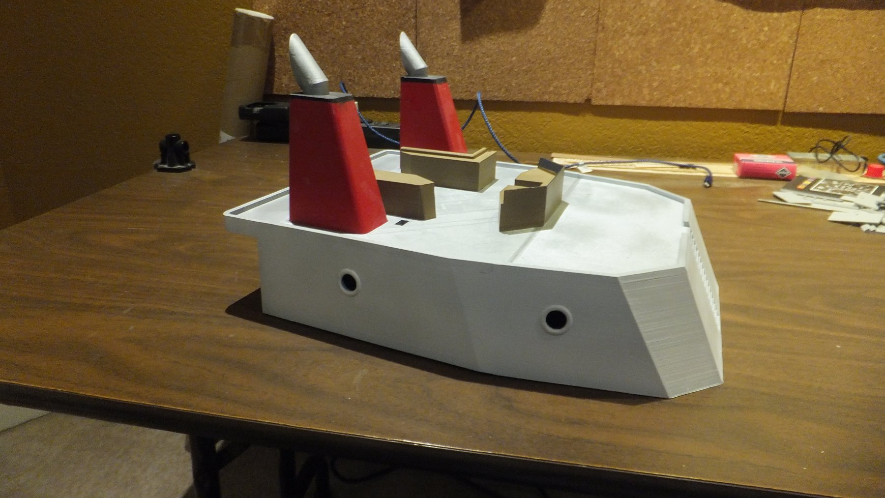
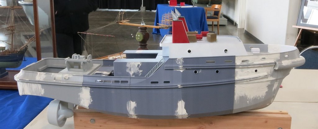
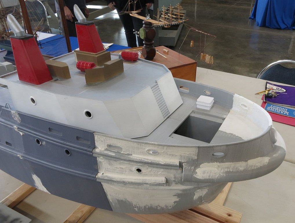
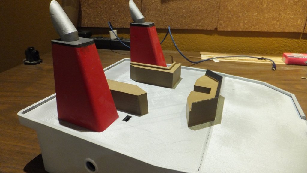
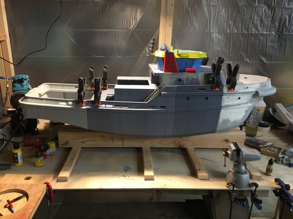
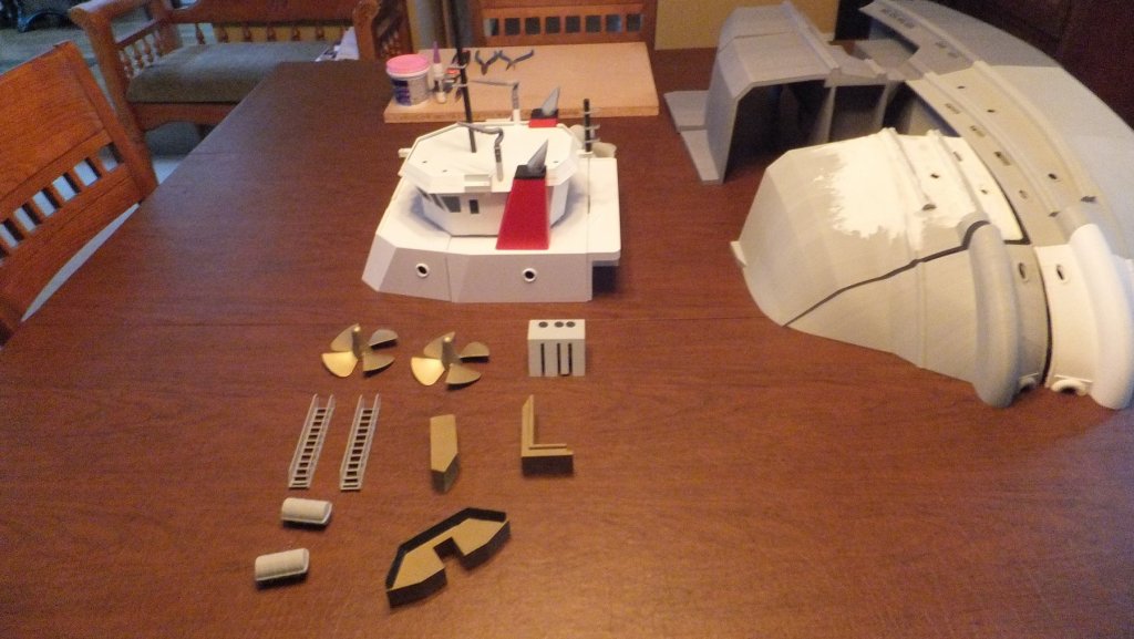
Ok, I thought you might like an update and some photos. On Friday last week I had a project meeting with the customer. We did a review of where we are at and we discussed the issue on the starboard side. He decided that he did not want me to do major surgery (Yahoo!!), and we came to an agreement on how to make it look better and that would be good enough. This past weekend we had a meeting of our local model building club and the photos you see below are the result. So let me explain a little bit of what you see. First of all I have used spackle to fill cracks etc. This is in preparation for sanding. The main cabin is just sitting on the deck. It is sanded and painted. you can also see the smoke stacks coming up thru the deck. the furniture for the pilot house is glued in place. and the life boat canisters are sitting on the roof of the main cabin. the Pilot house is not here because it is in the shop being wired for navigation lighting. It too has been sanded and painted. On the fore deck you will see the emergency hatch just sitting in place, it needs painting. The hole in the bow is for the forward winch. It was decided that since this will get a lot of hands on attention from the students it may need to be replaced & repaired. So we designed it so it could be removed. On the stern is the main winch. Similar to the forward winch it too can be removed. It is not complete yet but you can see the hole in the deck where it will be installed. It was requested that the thrusters rotate so the deck is not in place until they are painted and glued to the shaft.


- 133 replies
-
- 14
-
-
- alert class
- tugboat
- (and 1 more)
-
PLA Welding only works with 3 mm PLA. The 1.75 is too flexible. And yes I have been able to fill gaps and it does create a bead very similar to real welding. Neal - you and I can discuss this in person over the weekend. I will have the hull with me.
- 133 replies
-
- 4
-
-
- alert class
- tugboat
- (and 1 more)
-
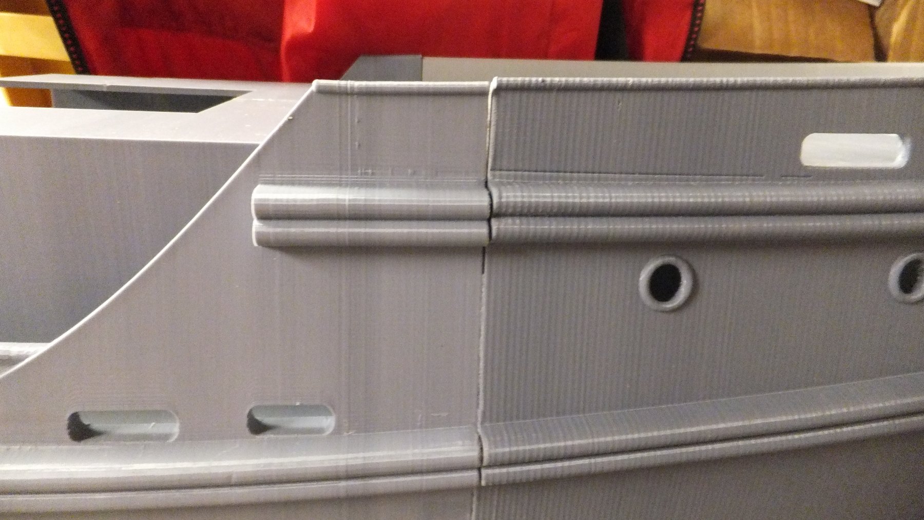
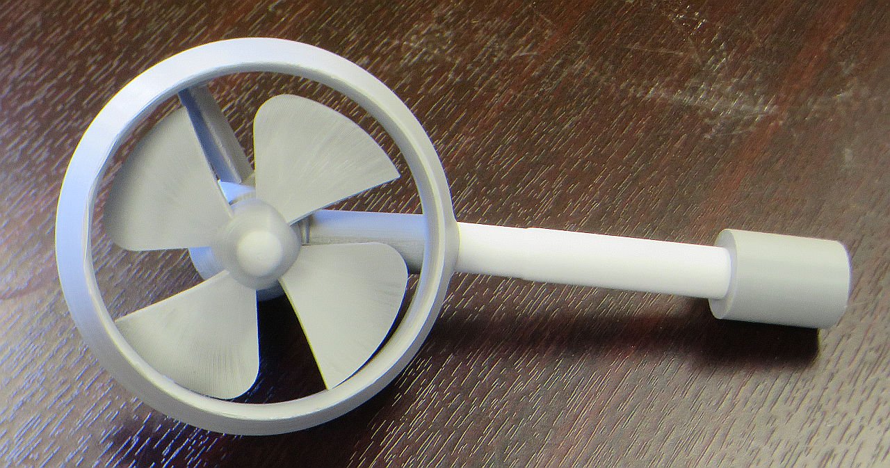
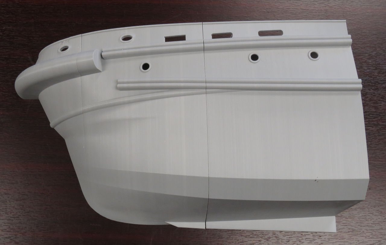
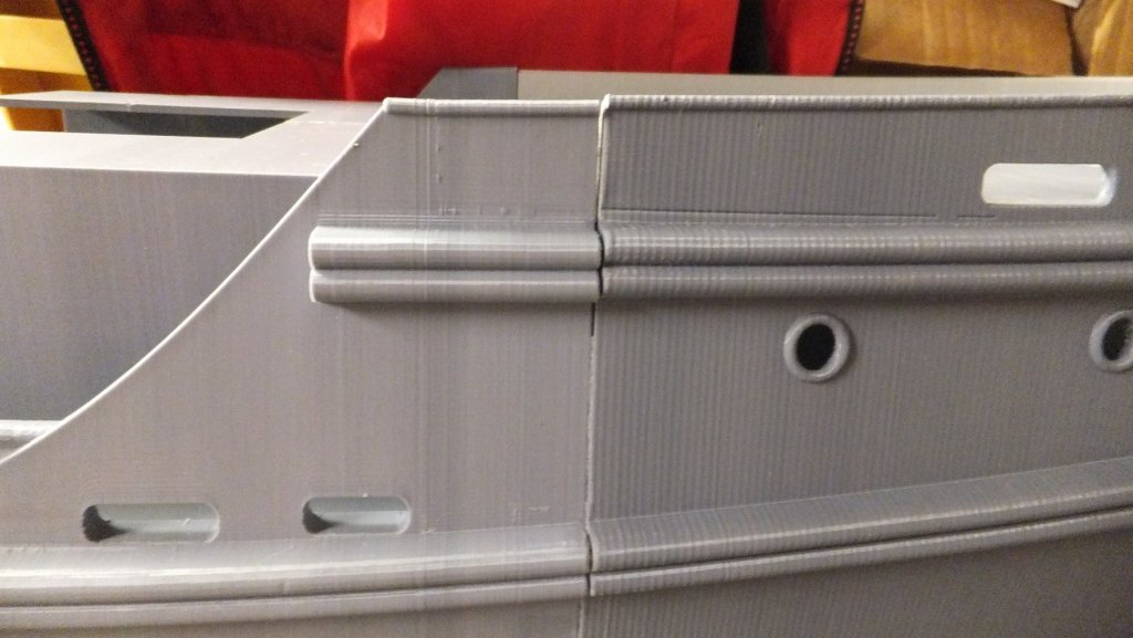
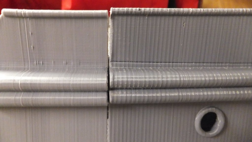
Ok, On this site we share both our success and our problems. If only to help others avoid the same mistakes. I have been plagued by a difficult problem that has created a significant delay in this project. As you will see in the attached pictures 2 of the hull sections do not line up correctly, and it is very noticeable. My suspicion of the cause is the many different 3D printers used and many different suppliers of filament. Out of 15 parts for the hull this is the only join that has such a large gap and does not line up. I should also mention that it does line up at the keel. So it is this section that needs to be modified so that if fits. Also the deck is out of alignment. My plan is to very carefully do some surgery on this part to lower the deck line so that the railing is lined up. Then I will use a technique call PLA welding to close the gap. PLA welding takes advantage of the low melting point of the filament and creates a bead in the gap between parts. Wish me luck. I have been ducking this for several days, hoping for a better solution. If I fail it will mean several pieces of the hull will need reprinting.
- 133 replies
-
- 9
-
-
- alert class
- tugboat
- (and 1 more)
-
I went to this museum in Sept. It was fascinating! One of the highlights of my vacation. I spent 3/4 of a day just here. The admiral waited for me in the café. I also heard that they are about to raise another section of this ship soon. I can't believe that some guy spent every weekend for 5 yrs diving and looking for the wreck.
-
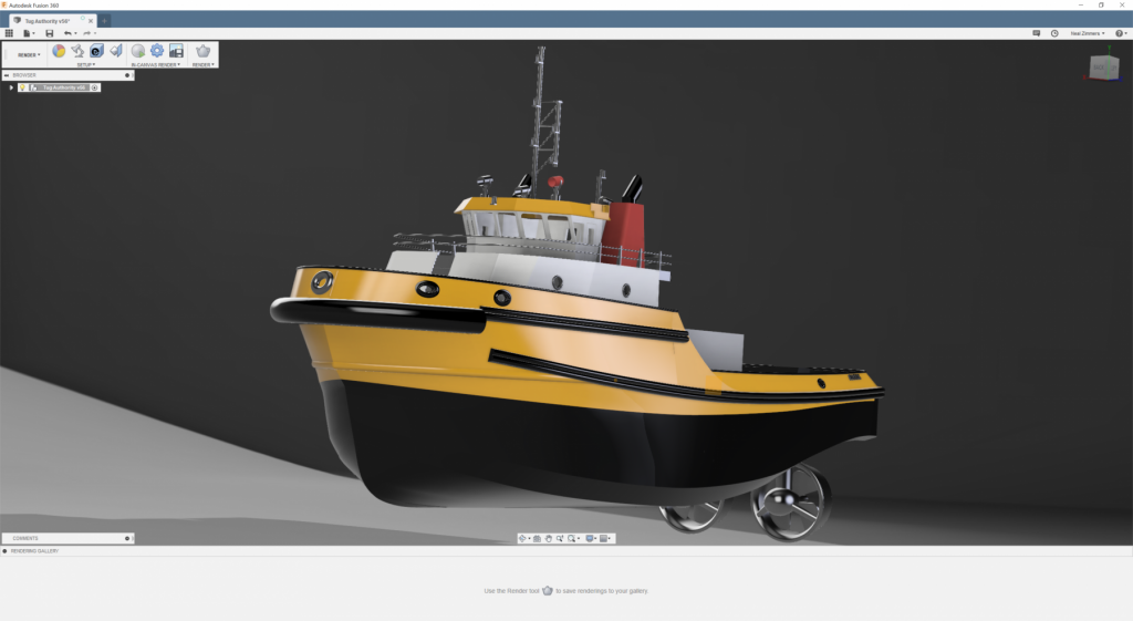
So first off, Neal is way too modest. He did all of the CAD design for the Tug, and it was not easy. We did receive PDFs from the designers. But there was a lot of detail omitted. Neal did all of this work. Also Neal has had to put up with my constant nagging "when will you have the STL files ready" "Please recreate this part" etc. Once he had completed the CAD design and shared the rendering (see above). I had the fun of sending everywhere and getting all the excited feedback. I believe it is that rendering that really sold this project. Also once we had the rendering Neal had to figure out how to slice the design so it would fit on the various 3D printers. Not an easy task. For this project I broke it into 3 major parts - Part 1 - Neal would do all the CAD work for the Tug Part 2 - Per would do all the CAD work for the Barge with support from Neal Part 3 - Floyd would handle all the admin (contracts, NDA, communication) & the 3D printing, assembly and painting of the models. And this includes the manufacture of the oil containment booms. Bill - You are exactly right. I will never do a project of this type the same way. In fact the barge will likely be foam and wood with some 3D printed details.
- 133 replies
-
- 6
-
-
- alert class
- tugboat
- (and 1 more)
-
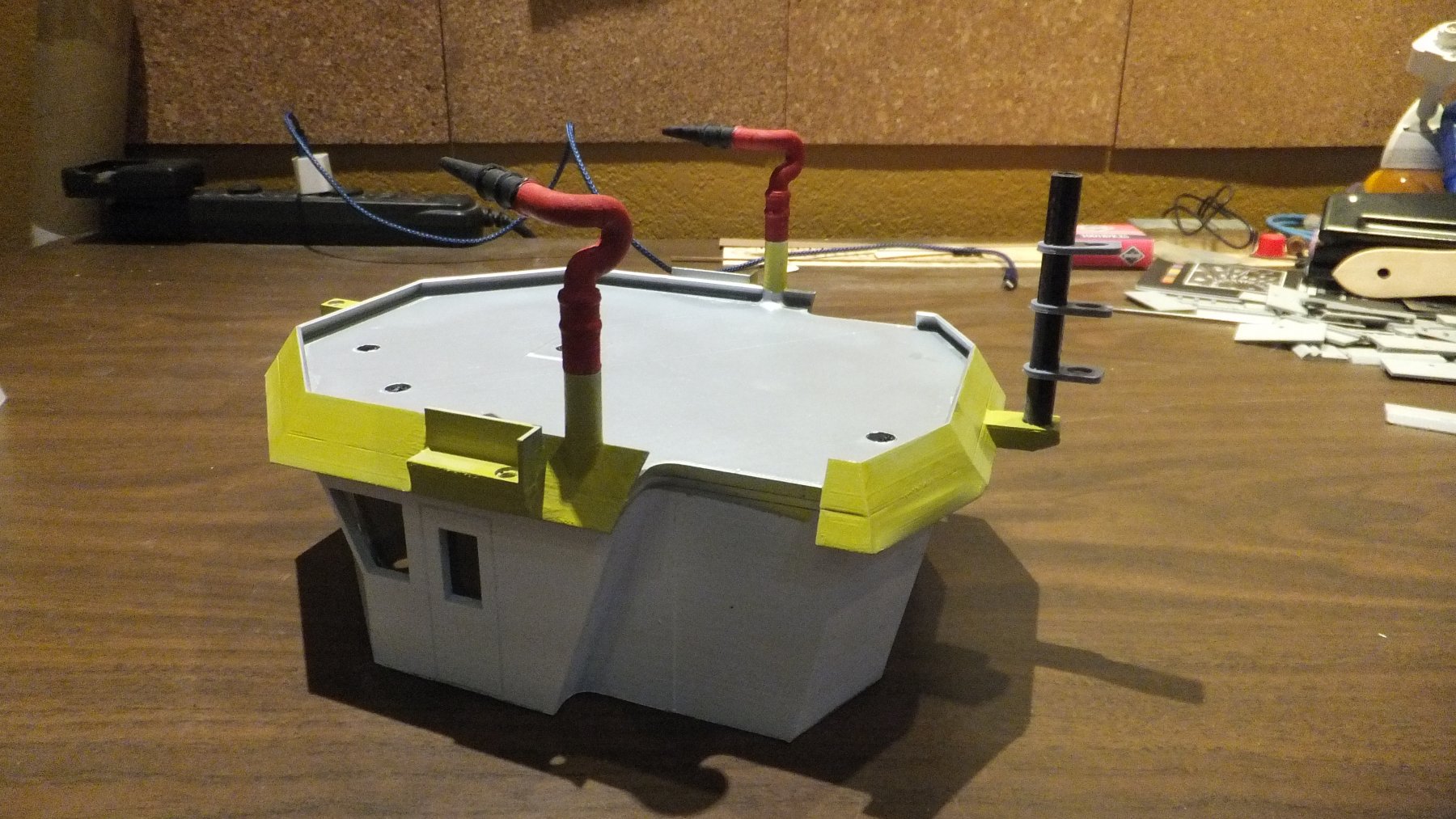
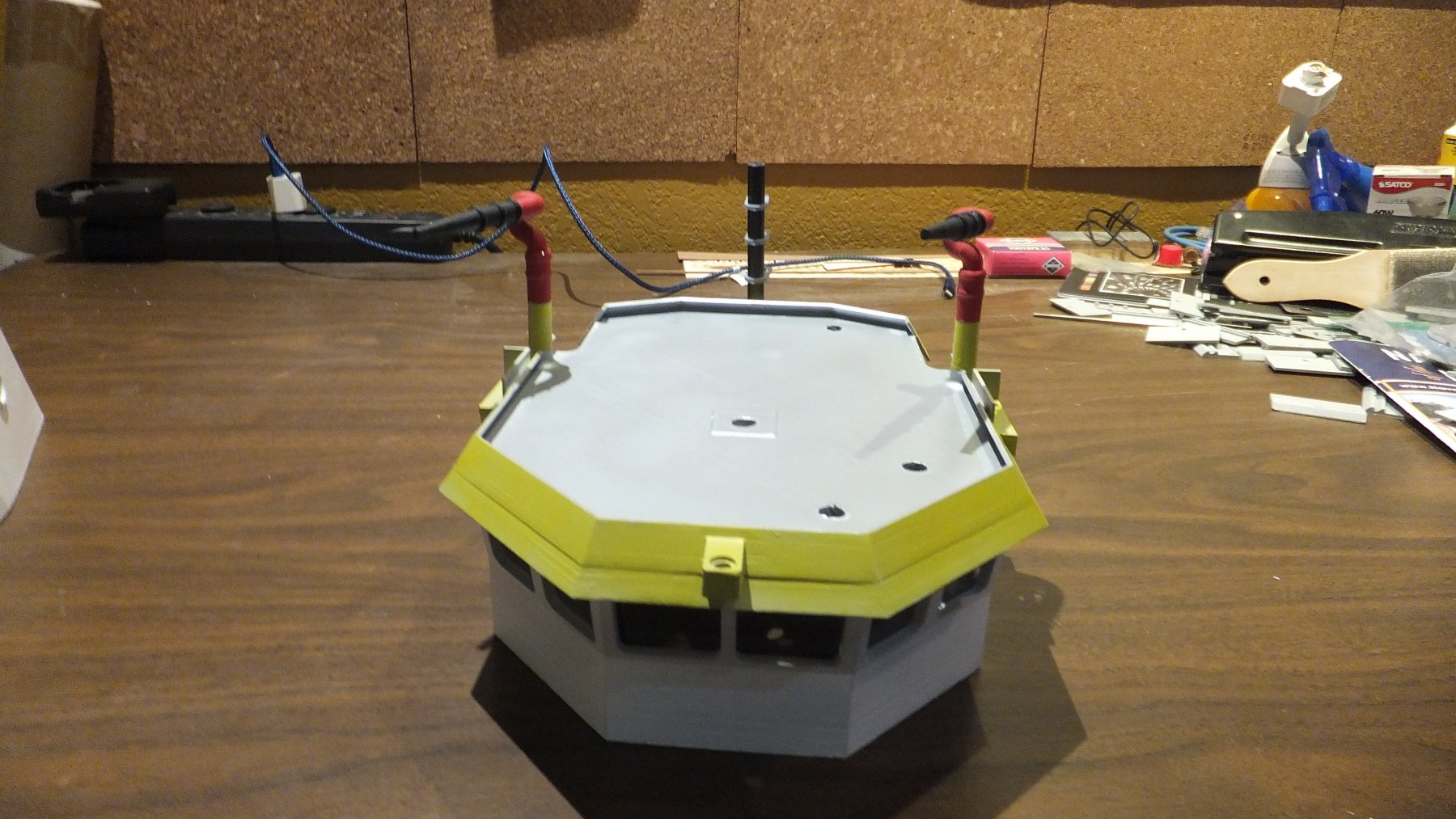
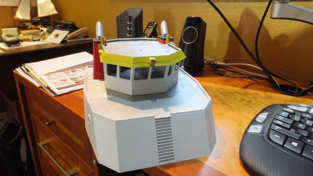
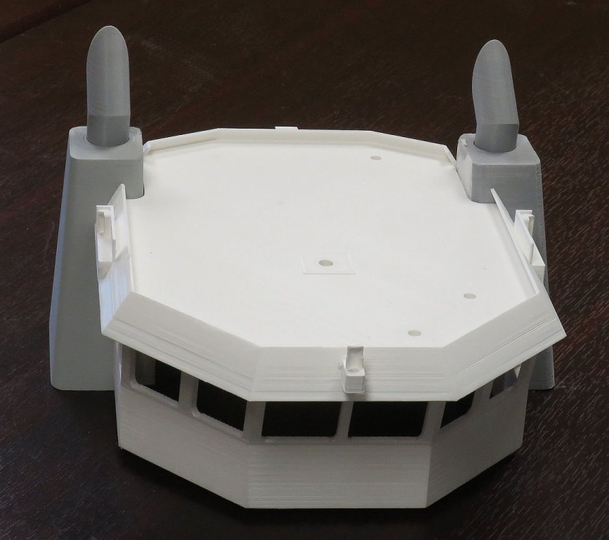
The masts are made of 8 mm carbon fiber. This is not to scale but it is necessary to get all the wires inside. Once the wiring is done I will place hoods over the LED to control the dispersion angle. The square holes are for the wiring from the lights in the pilot house. Main Cabin below -

- 133 replies
-
- 10
-
-
- alert class
- tugboat
- (and 1 more)
-
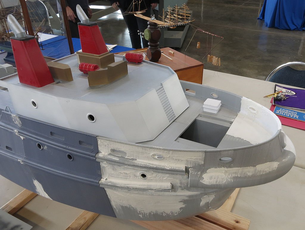
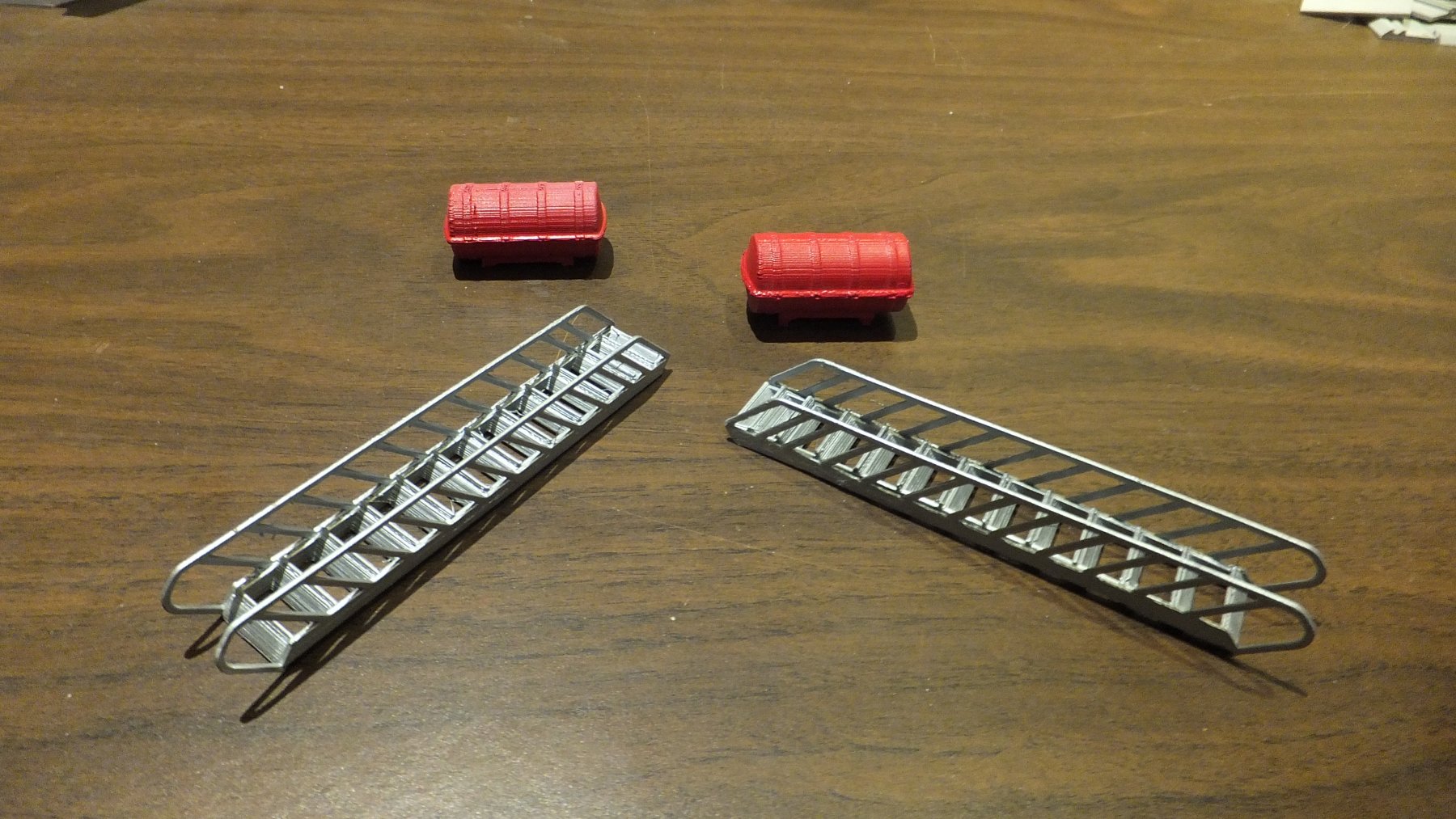
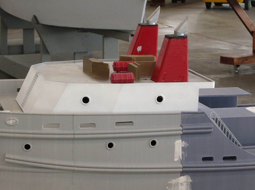
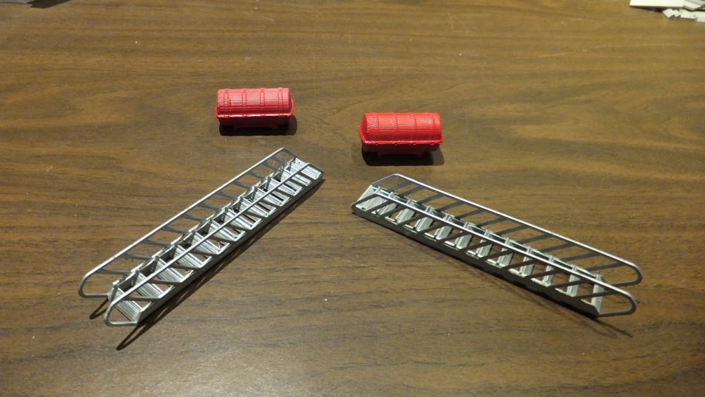
Ok here is a bit of an update. In the last photo you saw the main cabin with the pilot house sitting on top. Most of those parts were not glued in place. I was just anxious to see how it looked. Well as of today I have finished painting the fire nozzles and glued the stack and furniture in place. I also finished the windows and glued the short mast in place. There is also a picture of the ladder/stairs and the life boats. The stairs were 3D printed as 3 parts glued with CA then primed and painted. I am rather pleased with them. I have pictures of the life boats painted red & also painted white. So I chose red so they would stand out against the white walls. The fire nozzles are held in place with a magnet (nice idea Neal). The windows don't show well in the pictures, but they are there.


- 133 replies
-
- 11
-
-
- alert class
- tugboat
- (and 1 more)
-
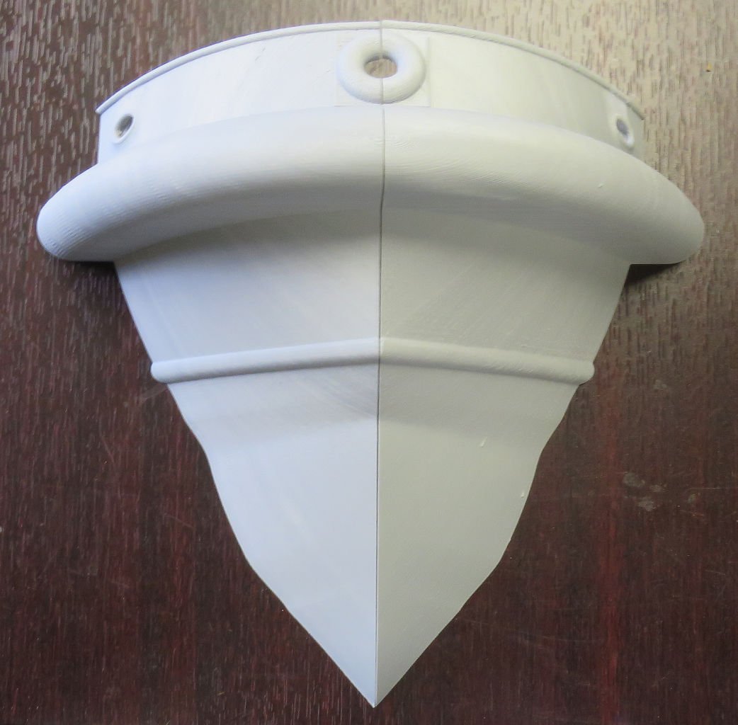
So First I would have to find out if this would be a violation of my NDA with Crowley. I should also mention that R/C was discussed with the school. They declined. The thruster Pods do rotate at the clients request. But, the props do not. this was to make them student proof. And the Oil booms will come as an addition not on a spool to rotate. But that could be done. I will have to discuss this with my engineering team. Frankly I am more interested in a different product. But that is too soon to discuss here. Give me a few weeks.
- 133 replies
-
- 4
-
-
- alert class
- tugboat
- (and 1 more)
-
Ben - The tugs belong to Crowley Marine. I am told they have a wholly owned design firm and they did the work. I will send you the most recent copy of the PSSM newsletter and add you to the distribution list. Also you live in one of my favorite towns. I might have to bug you the next time I am nearby.
- 133 replies
-
- 4
-
-
- alert class
- tugboat
- (and 1 more)
-
Ben - Besides being in this project. I am also the president of the Puget Sound Ship Modelers. Please PM me with your email address and your physical location. I will make sure you are invited to our events and added to the newsletter distribution. The ship yard was Dakota Creek in Anacortes.
- 133 replies
-
- 5
-
-
- alert class
- tugboat
- (and 1 more)
-
Yes it is kinda like when the doctor says "this won't hurt at all"
- 133 replies
-
- 9
-
-
- alert class
- tugboat
- (and 1 more)
-
Ok let me take a moment to tell you about the program that will be using this model in the classroom. The school is located in Astoria, Oregon. They have 120 students in the Maritime program. There are 18 instructors. The kids must be under the age of 26 and underprivileged. They have to meet an income requirement. That is family income below a certain level. They come from all over the US. They live on campus and the program consists of 18 months of classroom and 6 months of experience. At the end of the training. They must pass a few exams. If they complete the program and get a passing grade. They get certified by the US Coast Guard and Union membership. The Union takes on the responsibility of finding a job. Currently everyone who completes the program finds a job. One of the critical tests is Rules of the Road. The student must be able to look at the model,read the lights, and tell you what they stand for. He/She must also know the dispersion angle of all the lights. So my challenge is to get it right when I build the model. I don't want a student to fail just because I screwed up. Besides the learning that I am doing for this project. It is nice to know that all this work is going for a good cause.
- 133 replies
-
- 12
-
-
- alert class
- tugboat
- (and 1 more)
-
Shipmodel - now that I have done it. I would not recommend 3D printing for such a large project. Too much material and too much time. This project would have been much easier if I had just done it in wood.
- 133 replies
-
- 8
-
-
- alert class
- tugboat
- (and 1 more)
-
Druxey - I ahve myself to blame for the scope creep. when they said Navigation lighting. I was sure what that meant. Well a retired Coast Guard Chief has an entirely different definition than a casual boater like me. But the good news is now I have studied the COL Regs.
- 133 replies
-
- 5
-
-
- alert class
- tugboat
- (and 1 more)
-
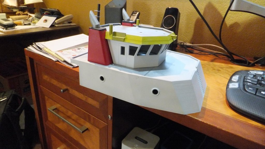
Ok so here is the progress for today. I sanded, primed, and painted the main cabin & Pilot house. The cabin walls are white. The Pilot house trim is yellow. and the decks are Steel color. The rear mast has been drilled to accept the LEDs that will be mounted there. about 1/2 of the windows are installed. While waiting for paint to dry. I worked on other pieces like the winch and crane. They have all been primed. I also primed all the fixtures for the main mast. After the windows are completed and the main mast has been drilled. We will begin wiring. You may note there are holes in the Pilot house roof for the 3 searchlights and the mast. The fire nozzles are almost ready to install.
- 133 replies
-
- 15
-
-
- alert class
- tugboat
- (and 1 more)
-
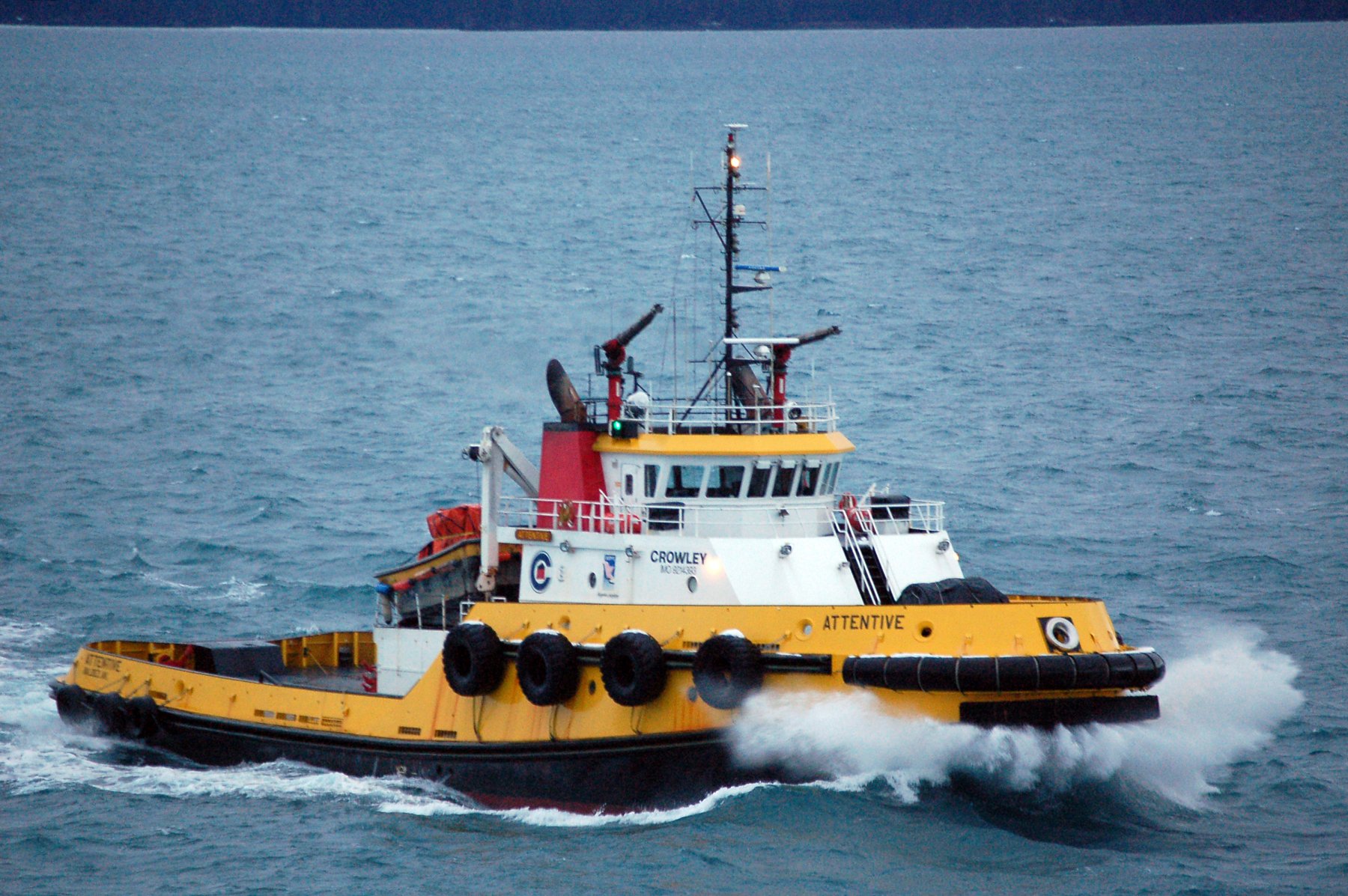
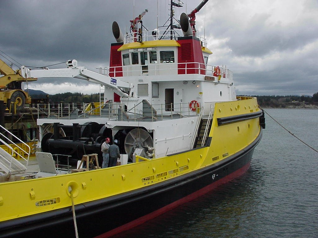
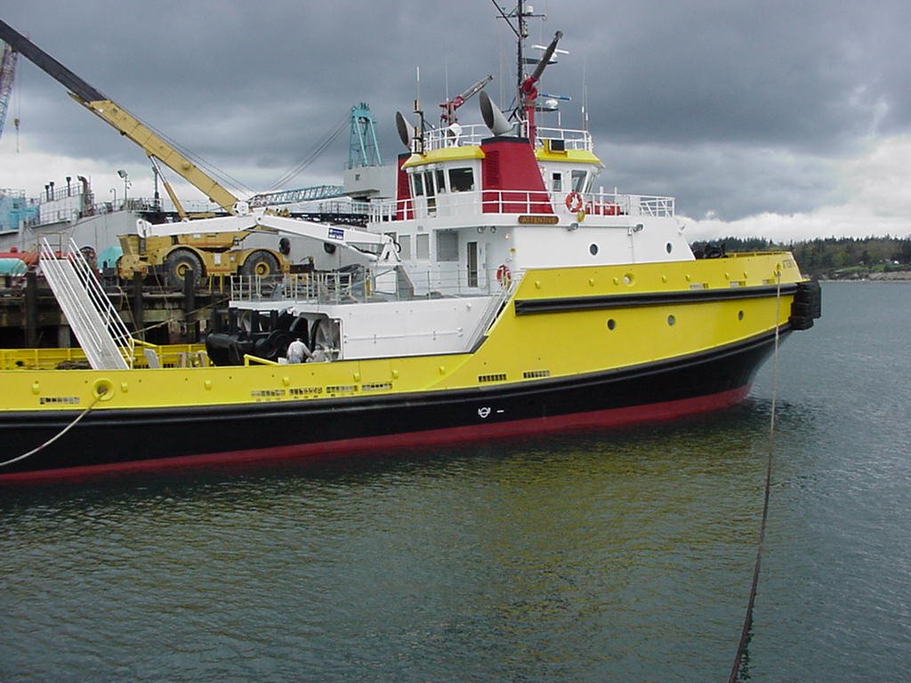
Ok while I am waiting for paint to dry let me provide some details about the real tug. After the Exxon Valdez disaster Alaska has implemented additional requirements for oil tankers in the area. This includes what is called a Ready Response tug. This tug escorts any tanker coming into the fuel terminal. And before any oil is moved the Ready Response tug deploys a containment boom around the vessel. The Alert class tugs (there are 3 of them) were designed specifically in response to these new regulations. the Alert carries 2000 feet of containment booms on board. she also had 2 skiffs to help deploy the booms. The alert has 2 fire cannons that can dispense a mixture of foam and water at the rate of 10,000 gallons a min. She also has a built in tank that can hold 50,000 gallons of crude if there is a spill. The school decided that if they were going to have a model it might as well have these additional features to demonstrate to the students. This season the Alert tugs were under bid and so they have returned to Seattle. Which allowed us the opportunity to be on board and take pictures. the pictures below are of the real vessel underway. All 3 tugs were built in a Washington ship yard.

- 133 replies
-
- 13
-
-
- alert class
- tugboat
- (and 1 more)
-
So a bit of detail for this group. The overall length of the tug model is 3 ft 9 inches. and the max size of bed on all the available 3D printers is 6 inches. so we had to slice the model into 7 slices or sections and then slice again down the keel. and for the final slice (section 7) we needed a flat surface for the printer bed. So section 7 became section 7A port, 7A starboard, & 7B. So a total of 15 hull pieces. I also had some issues with under extrusion. This was solved by using Spackle to fill. Tomorrow I will be using a process called PLA welding to fill the major cracks. Then comes the spackle and sanding. I found it a bit different to create a build board for a model of this size. I used some lengths of 2 X 4 and bolts as you can see below. PS to make the admiral happy I created a spray booth in my garage. And I am learning to air brush!
- 133 replies
-
- 15
-
-
- alert class
- tugboat
- (and 1 more)
-
Yes Dr. Per I do expect that you will post a rendering here soon.
- 133 replies
-
- 4
-
-
- alert class
- tugboat
- (and 1 more)
-
I should also mention that like any other project we had a bit of scope creep. When they asked if the model could have Navigation lighting. I said sure no problem. Since I had experience with lots of sailboats and power boats. I figured a light in the cabin, at the masthead, and red & green. no sweat. That is when I was invited to attend a 2 hr. class on the phone about Coast Guard regulations. In the end we will have 16 different circuits of LEDs with several colors. It was also agreed that I would create scale model oil containment booms to go along with the tug and barge. With reluctant help from the Admiral we purchased International Orange cloth and are manufacturing scale model containment booms. I should mention that no one was able to come up with plans for the barge. So work on that model had been significantly delayed. Finally in January we received detail design information for a barge that was twice as big as the one described in the contract. Dr. Per has been slaving away on this part of the project. And will likely complete the design review in the next couple of weeks. Meanwhile Floyd has been experiencing a very steep learning curve on 3D printing and slicing software. I would estimate that for every hull section successfully printed there are 2 failures. And did I mention how long it takes to do a 3D print? The hull consists of 15 sections due to the maximum size we can print a part. These Hull sections can take from 15 hours to 5 days to print.


- 133 replies
-
- 20
-
-
- alert class
- tugboat
- (and 1 more)
-
I have been very remiss in not posting this log. So let me make up for my omission. and please stay with me while I share my complicated story. In late July of 2018 a friend came to me and said "you build model boats don't you?" And when I said yes he handed me a piece of paper with a name and phone number on it. He said "Call this guy. he has money". And with that my adventure began. When I called the guy (his name is Mike) it turned out he is an instructor for a school that trains students for careers in the maritime industry. The school has a harbor tug that is approx. 70 years old and needs to be retired. They don't have a lot of money and came up with the idea of building a model of a tug as an inexpensive way to teach about a modern tug until they can raise the money for the real thing. So they offered me several $1000 to build this model and a fueling barge to go with it. They wanted a tug model that was approx. 4 feet long. As mentioned elsewhere in this site I have been learning Fusion 360 and experimenting with 3D printing. So I thought what a great opportunity to use these skills. Never in my wildest dreams could I have imagined what happened from here. Both good and bad. Thanks to this wonderful web site I already knew about someone who had used Fusion to make 6' long 3D printed Battleships. So my first contact was to get an estimate of what it would take and how long. I also knew that my good friend Dr. Per had much more experience in CAD than I have and reached out to him. So I won't go into all the details. but as it turned out This school is part of the federal government and it took several weeks to just get approval on how not to spend any US tax dollars to do this project. It took many more weeks to get connected to the company that designed the Tug. And finally with the help of an attorney and an NDA. We got to spend a day on board the tug here in Seattle and received partial plans. So the non modeling part of this project took 4 1/2 months. Neal was given 6 weeks to develop the CAD drawings and then we had a design review with the customer. All of this was completed 12/21/2018. And now we could start actually modeling. I should also mention that the project was being funded by donations from a 3rd party and it took a while but we got set up as a vendor to them and got paid an initial $500.00 to cover materials.
- 133 replies
-
- 13
-
-
- alert class
- tugboat
- (and 1 more)
-
Byrnes Table Saw
fnkershner replied to WSparrowHood's topic in Modeling tools and Workshop Equipment
I have had mine for 6 years. I love everything about it. I also echo what has been said above. I bought all the extras. I have used them all. But I find I don't really need to tilt table. -
3D printing Rigging blocks
fnkershner replied to AntonyUK's topic in CAD and 3D Modelling/Drafting Plans with Software
I would suggest either Onshape or Fusion 360 for this. And Wefalck I think you are over thinking the design. I can easily print the shape of a block with either of these Software choices including the Sheave. But I do agree the scale will be challenging. I also suggest you will be painting to get the wood look. make or buy out of wood is going to be faster and possibly cheaper. -
CDW - The Non profit lab I am a member of will teach you to build your own for about $300 to $400. Plus 2 weekends of effort. The results are very good.
-
Neal - thanks for bringing this model to the meeting. It looks even better in person than in these Photos. I hope you will come often we will be very interested in your progress. Also thanks for the tips on my Fusion 360 project. Unfortunately my other projects have kept me away from trying them as yet.