
.JPG.ca33079f5815b861e67b9c2cccd37982.JPG)

Blue Ensign
-
Posts
4,498 -
Joined
-
Last visited
Content Type
Profiles
Forums
Gallery
Events
Posts posted by Blue Ensign
-
-
Hi Jason, that's how I did it on Pegasus, except I didn't mark in the scarph joint, nicely done

B.E.
-
I like the innovations you have made to your build Robert, very nice work.
Well done.
B.E.
-
A simple man’s guide to sail making (part two)
The sail has been cut out complete with a hem all the way round, the positions of the cringles have been marked along the edges.
The hems are folded over and a small slit where the cringles are to be placed is made with the scalpel.
0.1mm line is then placed along the hem inside the fold and fished thro with a small pointy thing, to form the cringles.
This is the position so reached.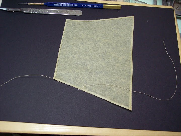
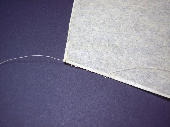
After the first few cringles have been formed the hem is glued down using neat PVA to hold the cringles in place.
In the pic below all the cringles have now been put into place.
Down each side from the top are the three pairs of Reef cringles, followed by three Bowline cringles; the leech line is attached thro’ the top two.
At the clue is the cringle for the blocks..
Across the foot of the sail are the cringles for the buntlines.
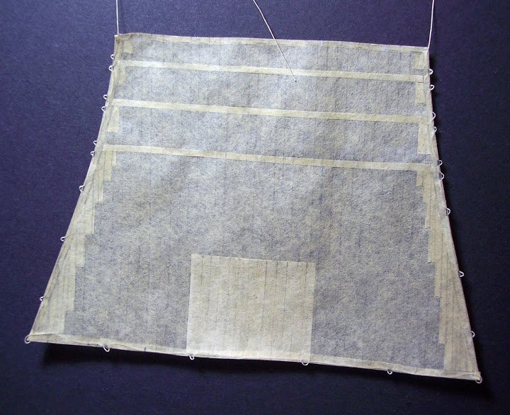
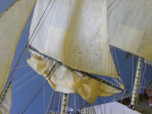
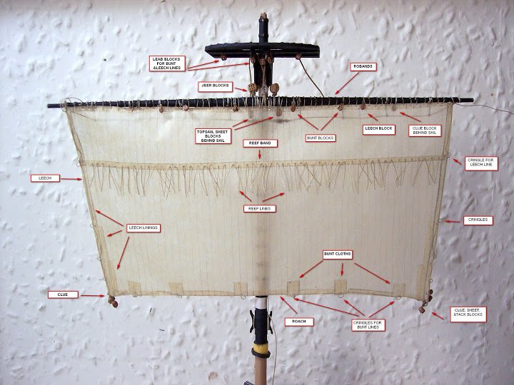
Bands, patches and linings
Additional strengthening pieces of ‘cloth’ are now required to be added to the sail. These are all attached to the aft side of the sail as shown above (Fore side on British ships.)
They comprise:
The reef bands, three narrow strips thro’ which the reef points are fixed.
The Patches small squares of material below the reef cringles at the leech.
The Top lining, the most distinctive addition whose purpose is to protect the sail from wear by friction against the mast top.
The Lining cloths which are strengthening strips staggered down the leech of the sail.A bit like wallpapering this part, cut it to size, slap on the paste, and stick it down.
With the light behind the full effect of the various additions can now be seen.
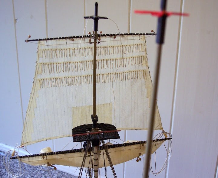
A series of holes were drilled thro’ the Reef bands to take the Reef points, and again on the Head lining to take the Robands.
Some 150 reef points are required on the Topsail.
Once the sails are in place they can be manipulated at any later stage by the simple expediency of wetting them down.
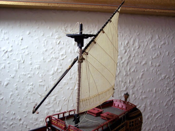
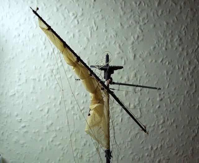
The Mizen sail, the Brails that control the sail furling are all in place, there are matching lines on each side of the sail.
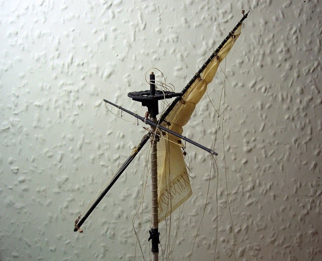
a simple wet down of the sail and haul on the Brails and the sail is loosely furled.
Modelspan is a tough material and in my workings with I had no failures.
I would use modelspan for kitting out models certainly up to 1:96 scale.
Cheers,
B.E.
- FrankWouts, daHeld, garyshipwright and 18 others
-
 20
20
-
 1
1
-
Just for you JP I'll dig out my posts on the subject.
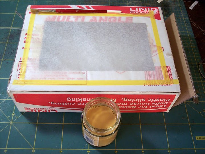
A Simple man’s guide to small scale sail making.
For this I used modelspan tissue at 21gsm.
This is where it all starts, my patent jig for sail making.
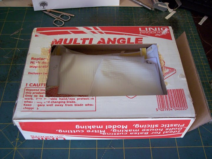
Well alright it’s a box with a hole cut into it.
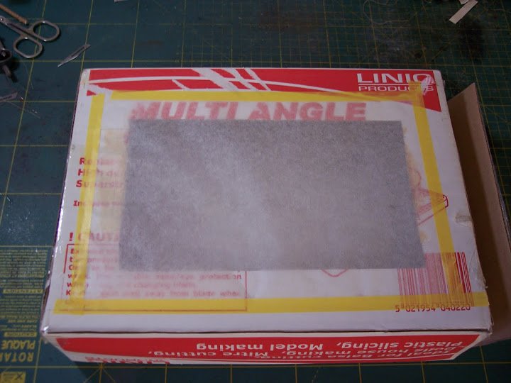
The Modelspan tissue is taped over the hole – make sure the hole is large enough for the sail dimensions.
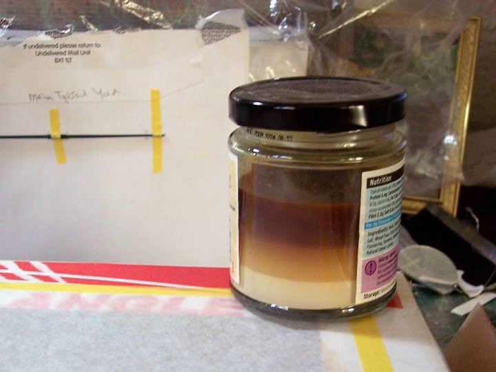
The witches brew – ear of bat, eye of toad, you know the sort of thing - actually pva diluted to the consistency of milk with a little yellow ochre paint added.
Once the potion is mixed it takes on a fetching ochre colour.
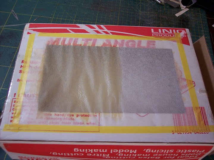
The potion being applied, note the colour change and how the tissue has started to sag.
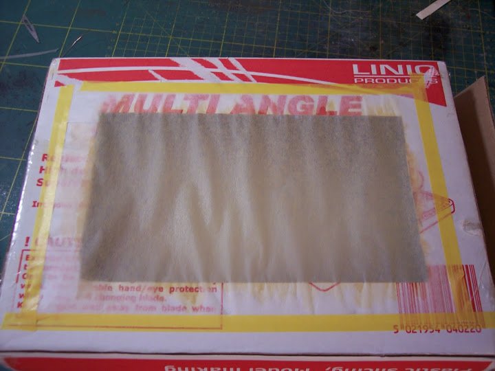
The completed effect, just needs to be set aside to dry............. but if you’re impatient like me...
A quick blast with the CPO’s hairdryer, diffuser in place – and were ready to go.
The tissue is now as tight as drum skin and much the same colour, a little more ochery than appears in the photo.
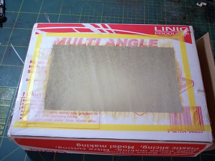
The sail ‘material’ is removed by cutting around the edges of the hole with a scalpel, or any other such sharp implement that is to hand, and is taped over the drawing as previously made.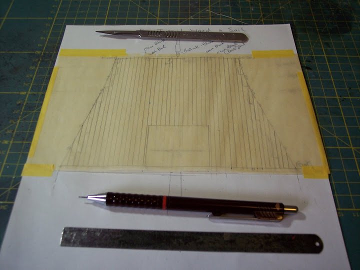
I had previously drawn out a scaled sail from the works of Jean Boudriot.
The lines are transferred and the fiddly business of making the sail up begins.
This will be the subject of the next post.
B.E.
-
Hello Dave, 2.5mm diameter stuff does seem a bit on the heavy side for Mars it equates to a 19"+ circumference cable.
According to Lees the anchor cables in circumference inches were 0.62 of the Mainmast dIameter in inches.
Another method based on older writings gives the sheet cable circumference as commonly being so many half inches as your ship's breadth in feet at midships.
It would be interesting to see what size cable comes up if you apply the above to Mars.
Something between say 11.5" and 13" circumference is my best guess for Mars, equating to scale line with a diameter of 1,5mm - 1.7mm.
with anchor cable regardless of scale I tend to go with what suits my eye, and with my Pegasus build I have both 1.5mm and 1.75mm line to decide between.
David Antscherl in ffm IV indicates a 13" cable for Pegasus (scale 1.64mm diameter line) Using the Lees factor of 0.62 of Mainmast diameter (183/8th ") it works out at 11.4" circ. = to 1.44mm diameter scale line.
As for puddening old worn rope was used in the order of 2" to 2.5" circs equating to 0.25mm diameter or perhaps 0.3mm.
So less than they indicate in the kit.
Confused? - I know I am

Cheers,
B.E.
-
Thank you Daniel, I'm glad you like it
Cheers,
B.E.
-
Hi Jason, not a very good photo but this is the spectacle plate on my Pegasus.

It is effectively just a metal band like the rudder straps, with an eyebolt secured on the outside corners to which the chain is attached.
As for chain I agonise over the scale every time I come to use it, but my best estimate for rudder chains at 1:64 for this purpose is is chain with 16 links to the inch. The chain is attached to a couple of eyebolts spaced along under the transom, to which the rudder pendant is attached and taken inboard.
Mostly models just show the chains.
B.E.
-
Hi Ian, here's the link to the model in the NMM.
http://collections.rmg.co.uk/collections/objects/66418.html
Looking at that model again it appears that she has eight swivel posts along the Quarterdeck rail, but the aftermost post on the starboard side appears to have broken off.
Thanks for looking at my Pegasus, glad you are enjoying it.
Regards,
B.E.
-
Hi Lukas, now I understand,
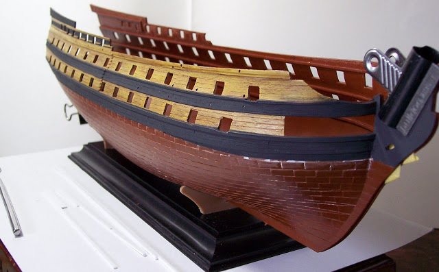
The absence of planking lines along the hull was the first job I attended to in the build. There is 9mm between the wales and I inscribed four lines of planking using styrene strip guides of one, two, and three widths to guide the probe, these sit against the wale edge and given the fairly small scale seem to work fine.The scribing was done with a curved Dental probe.
The butt ends were scribed in, and the grain pattern already on the mouldings reduced a little.
A jig made from polystyrene packing was used to support the hull half whilst the scribing was done.
The Wales
Fortunately Boudroit does not indicate anchor stock planking for the wales, so these were also scribed as above.
The fair run of coppering
This does present a slight problem, and looks odd to my eye the way it follows the wale around the hull which doesn’t seem to take into account any sheer.
Starting at the centre of the hull side, tape was applied beneath the wale and carried straight to the bows and stern, so it dropped below the wale by one strake at the bows and by about five strakes at the stern extreme.
Where the plating has been removed it is necessary to fill and smooth the edges and scribe planking lines.
At first sight I thought the plates looked over scale, but on checking using 4’ as a norm, they are in fact ok for length if a tad too deep.
One thing I would do differently at the outset is to glue the hawse hole sections to the hull halves so that a consistent paint finish can be achieved along the hull.
I don't think you will have any trouble putting the kit together as an out of box build, and if it's your first period ship build it may be wise not to be too ambitious with modifications. just enjoy the build and make a few changes that you feel comfortable with.
Cheers,
B.E.
-
Thank you Lukas, the only reason I could do such a kit bash on this model was that I had the superb works by Jean Boudriot to refer to - The Seventy four gun ship.
I also bought both the Heller kits Le Superbe, and Le Glorieux and used bits from both of them.
I'm not quite sure which wooden beam structures on the Upper Hull you are referring to, can you elaborate?
As for tips I'm not sure where I could start, but I am happy to answer any questions you may have on your build.
Regards,
B.E.
-
I like the approach you are taking with your build, and those repacement tackle blocks on the carronades look so much better. Oversize blocks are one fitting that immediately catch my eye, and I can't live with them either.
I've not come across a kit yet that supplies correctly scaled blocks.
Cheers,
B.E.
-
Cheers Mark, trouble is the whole log runs for 196 pages with 550 photos, I think it would have become a life's work re-posting it.

B.E.
- riverboat and FrankWouts
-
2
-
Hi Jason that looks excellent, I used a small bulldog clip along the bottom of the keel/rudder to hold the rudder firm whilst I worked on it, fitting the tiller etc; Do the Jotika instructions include any reference to the fitting of rudder chains/pendants? they would usually connect to what is called a spectacle plate fixed just below the hancing on the rudder.
B.E.
-
Hi Frank I think you've really nailed the look of a hard worked vessel and I think you have got the colouring/weathering of the sails just fine.
I like the look of her.
B.E.
-
Hello Ian, it may be that swivels were not fitted in that location, do you have a particular class of Frigate in mind. The usual indication of a swivel gun is the stock into which it fitted. there were usually more stocks than swivel guns carried.
The only contemporary model with a beakhead bulkhead I have seen with swivel stocks is of a sixth rate 24 gun ship cica 1740.
this had stocks for swivels on the foc'sle (two each side) the foremost one aft of the cathead.
B.E.
-
Hi Mike, one of the reasons is that sanding sometimes smears the caulking whereas scraping does not; I always scrape decks.
I use an old plane blade out of bullnose plane, but hobby knife chisel blades are good for tight areas. Generally I use the widest blade I can to cover the deck area to reduce the possibility of digging into the deck.
Cheers,
B.E.
-
Cheers Steve, I'm glad you like it.
The Heller Le Superbe/Glorieux are the only game in town if a medium sized plastic Seventy -four model is wanted.
At least it can be fully rigged and displayed without the where are you going to put that ! comment from the Domestic Goddess
B.E.
- foxy, gary r and FrankWouts
-
3
-
-
Hi Jason, that's an interesting question.
The authentic way varied depending on the purpose of the block, but for attaching to an eyebolt the strop of the block would be seized to the eyebolt, but at model scale this can produce a too heavy look in my opinion.
At the scales I usually work at my approach has been to produce a knot as small and neat as possible, and without much regard to authenticity. I have taken the view that an unobtrusive knot is better than an over scale authentic one.
On Pegasus I resolved to do better but I have only really rigged the tiller lines so far and I used a false splice method originally explained by Gil Middleton in his Victory build, and also used by Dafi, he did a post on it in the masting and rigging section.
Apart from the jeer blocks most of the rigging blocks on Pegasus are of 2mm or 3mm size quite small to replicate the strop and seizing in a truly authentic way without the line overpowering the block.As we have lost all the previous discussion items on the subject, I too would be interested to see how others have tackled the isue, particularly at 1:64 scale.
Cheers,
B.E.
-
Thank you Augie for your kind words, the log wasn't there to be aware of until last week as it wasn't on the old MSW. I posted it here from my original forum to bulk up the depleted content on new MSW and add to the range of kits covered.
I also repeated my current Pegasus build which I will continue to update now in 'real time'
Cheers,
B.E
-
Hi Augie, I seem to have missed your log the first time around, a fine looking kit and a fine looking build.
Nice work.
B.E.
-
-
A magnificent build Gil that I followed on the old MSW. I am pleased to see it back.
Your Victory is an inspiration to all builders and I have benefitted greatly from your approach to various aspects of the build. Your false splice is one that comes to mind.
Regards,
B.E.
-
Splendid work Jan, I love the sheer lines on that model.
B.E.
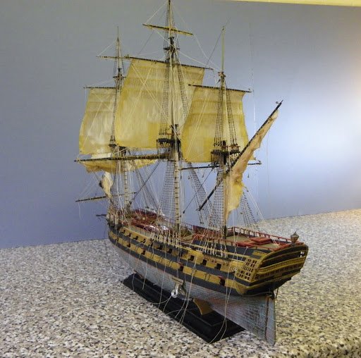
Le Superbe by Blue Ensign - FINISHED - Heller - PLASTIC - Built as "Le Praetorian", after Boudriot
in - Kit build logs for subjects built from 1751 - 1800
Posted
Thanks guys for your support of my build.
Lukas, the model is all handpainted, I think it gives a more appropriate finish to period ships.
Regards,
B.E.